WO2018105741A1 - クレーン - Google Patents
クレーン Download PDFInfo
- Publication number
- WO2018105741A1 WO2018105741A1 PCT/JP2017/044234 JP2017044234W WO2018105741A1 WO 2018105741 A1 WO2018105741 A1 WO 2018105741A1 JP 2017044234 W JP2017044234 W JP 2017044234W WO 2018105741 A1 WO2018105741 A1 WO 2018105741A1
- Authority
- WO
- WIPO (PCT)
- Prior art keywords
- obstacle
- crane
- camera
- traveling
- boom
- Prior art date
Links
- 238000001514 detection method Methods 0.000 claims abstract description 41
- 238000010586 diagram Methods 0.000 description 9
- 238000012544 monitoring process Methods 0.000 description 6
- 238000000034 method Methods 0.000 description 4
- 238000003384 imaging method Methods 0.000 description 3
- 240000004050 Pentaglottis sempervirens Species 0.000 description 2
- 235000004522 Pentaglottis sempervirens Nutrition 0.000 description 2
- 238000006243 chemical reaction Methods 0.000 description 2
- 238000004804 winding Methods 0.000 description 2
- 230000005540 biological transmission Effects 0.000 description 1
- 238000009434 installation Methods 0.000 description 1
Images


Classifications
-
- E—FIXED CONSTRUCTIONS
- E02—HYDRAULIC ENGINEERING; FOUNDATIONS; SOIL SHIFTING
- E02F—DREDGING; SOIL-SHIFTING
- E02F9/00—Component parts of dredgers or soil-shifting machines, not restricted to one of the kinds covered by groups E02F3/00 - E02F7/00
- E02F9/26—Indicating devices
- E02F9/261—Surveying the work-site to be treated
- E02F9/262—Surveying the work-site to be treated with follow-up actions to control the work tool, e.g. controller
-
- B—PERFORMING OPERATIONS; TRANSPORTING
- B66—HOISTING; LIFTING; HAULING
- B66C—CRANES; LOAD-ENGAGING ELEMENTS OR DEVICES FOR CRANES, CAPSTANS, WINCHES, OR TACKLES
- B66C13/00—Other constructional features or details
- B66C13/16—Applications of indicating, registering, or weighing devices
-
- B—PERFORMING OPERATIONS; TRANSPORTING
- B60—VEHICLES IN GENERAL
- B60R—VEHICLES, VEHICLE FITTINGS, OR VEHICLE PARTS, NOT OTHERWISE PROVIDED FOR
- B60R1/00—Optical viewing arrangements; Real-time viewing arrangements for drivers or passengers using optical image capturing systems, e.g. cameras or video systems specially adapted for use in or on vehicles
- B60R1/20—Real-time viewing arrangements for drivers or passengers using optical image capturing systems, e.g. cameras or video systems specially adapted for use in or on vehicles
- B60R1/22—Real-time viewing arrangements for drivers or passengers using optical image capturing systems, e.g. cameras or video systems specially adapted for use in or on vehicles for viewing an area outside the vehicle, e.g. the exterior of the vehicle
- B60R1/23—Real-time viewing arrangements for drivers or passengers using optical image capturing systems, e.g. cameras or video systems specially adapted for use in or on vehicles for viewing an area outside the vehicle, e.g. the exterior of the vehicle with a predetermined field of view
- B60R1/27—Real-time viewing arrangements for drivers or passengers using optical image capturing systems, e.g. cameras or video systems specially adapted for use in or on vehicles for viewing an area outside the vehicle, e.g. the exterior of the vehicle with a predetermined field of view providing all-round vision, e.g. using omnidirectional cameras
-
- B—PERFORMING OPERATIONS; TRANSPORTING
- B60—VEHICLES IN GENERAL
- B60R—VEHICLES, VEHICLE FITTINGS, OR VEHICLE PARTS, NOT OTHERWISE PROVIDED FOR
- B60R1/00—Optical viewing arrangements; Real-time viewing arrangements for drivers or passengers using optical image capturing systems, e.g. cameras or video systems specially adapted for use in or on vehicles
- B60R1/20—Real-time viewing arrangements for drivers or passengers using optical image capturing systems, e.g. cameras or video systems specially adapted for use in or on vehicles
- B60R1/22—Real-time viewing arrangements for drivers or passengers using optical image capturing systems, e.g. cameras or video systems specially adapted for use in or on vehicles for viewing an area outside the vehicle, e.g. the exterior of the vehicle
- B60R1/28—Real-time viewing arrangements for drivers or passengers using optical image capturing systems, e.g. cameras or video systems specially adapted for use in or on vehicles for viewing an area outside the vehicle, e.g. the exterior of the vehicle with an adjustable field of view
-
- B—PERFORMING OPERATIONS; TRANSPORTING
- B66—HOISTING; LIFTING; HAULING
- B66C—CRANES; LOAD-ENGAGING ELEMENTS OR DEVICES FOR CRANES, CAPSTANS, WINCHES, OR TACKLES
- B66C13/00—Other constructional features or details
-
- B—PERFORMING OPERATIONS; TRANSPORTING
- B66—HOISTING; LIFTING; HAULING
- B66C—CRANES; LOAD-ENGAGING ELEMENTS OR DEVICES FOR CRANES, CAPSTANS, WINCHES, OR TACKLES
- B66C13/00—Other constructional features or details
- B66C13/18—Control systems or devices
- B66C13/46—Position indicators for suspended loads or for crane elements
-
- B—PERFORMING OPERATIONS; TRANSPORTING
- B66—HOISTING; LIFTING; HAULING
- B66C—CRANES; LOAD-ENGAGING ELEMENTS OR DEVICES FOR CRANES, CAPSTANS, WINCHES, OR TACKLES
- B66C23/00—Cranes comprising essentially a beam, boom, or triangular structure acting as a cantilever and mounted for translatory of swinging movements in vertical or horizontal planes or a combination of such movements, e.g. jib-cranes, derricks, tower cranes
- B66C23/18—Cranes comprising essentially a beam, boom, or triangular structure acting as a cantilever and mounted for translatory of swinging movements in vertical or horizontal planes or a combination of such movements, e.g. jib-cranes, derricks, tower cranes specially adapted for use in particular purposes
- B66C23/36—Cranes comprising essentially a beam, boom, or triangular structure acting as a cantilever and mounted for translatory of swinging movements in vertical or horizontal planes or a combination of such movements, e.g. jib-cranes, derricks, tower cranes specially adapted for use in particular purposes mounted on road or rail vehicles; Manually-movable jib-cranes for use in workshops; Floating cranes
-
- B—PERFORMING OPERATIONS; TRANSPORTING
- B66—HOISTING; LIFTING; HAULING
- B66C—CRANES; LOAD-ENGAGING ELEMENTS OR DEVICES FOR CRANES, CAPSTANS, WINCHES, OR TACKLES
- B66C23/00—Cranes comprising essentially a beam, boom, or triangular structure acting as a cantilever and mounted for translatory of swinging movements in vertical or horizontal planes or a combination of such movements, e.g. jib-cranes, derricks, tower cranes
- B66C23/88—Safety gear
- B66C23/94—Safety gear for limiting slewing movements
-
- E—FIXED CONSTRUCTIONS
- E02—HYDRAULIC ENGINEERING; FOUNDATIONS; SOIL SHIFTING
- E02F—DREDGING; SOIL-SHIFTING
- E02F9/00—Component parts of dredgers or soil-shifting machines, not restricted to one of the kinds covered by groups E02F3/00 - E02F7/00
- E02F9/26—Indicating devices
-
- B—PERFORMING OPERATIONS; TRANSPORTING
- B60—VEHICLES IN GENERAL
- B60R—VEHICLES, VEHICLE FITTINGS, OR VEHICLE PARTS, NOT OTHERWISE PROVIDED FOR
- B60R2300/00—Details of viewing arrangements using cameras and displays, specially adapted for use in a vehicle
- B60R2300/80—Details of viewing arrangements using cameras and displays, specially adapted for use in a vehicle characterised by the intended use of the viewing arrangement
- B60R2300/8093—Details of viewing arrangements using cameras and displays, specially adapted for use in a vehicle characterised by the intended use of the viewing arrangement for obstacle warning
-
- B—PERFORMING OPERATIONS; TRANSPORTING
- B66—HOISTING; LIFTING; HAULING
- B66C—CRANES; LOAD-ENGAGING ELEMENTS OR DEVICES FOR CRANES, CAPSTANS, WINCHES, OR TACKLES
- B66C2700/00—Cranes
- B66C2700/03—Cranes with arms or jibs; Multiple cranes
- B66C2700/0321—Travelling cranes
- B66C2700/0357—Cranes on road or off-road vehicles, on trailers or towed vehicles; Cranes on wheels or crane-trucks
- B66C2700/0364—Cranes on road or off-road vehicles, on trailers or towed vehicles; Cranes on wheels or crane-trucks with a slewing arm
- B66C2700/0371—Cranes on road or off-road vehicles, on trailers or towed vehicles; Cranes on wheels or crane-trucks with a slewing arm on a turntable
-
- E—FIXED CONSTRUCTIONS
- E02—HYDRAULIC ENGINEERING; FOUNDATIONS; SOIL SHIFTING
- E02F—DREDGING; SOIL-SHIFTING
- E02F9/00—Component parts of dredgers or soil-shifting machines, not restricted to one of the kinds covered by groups E02F3/00 - E02F7/00
- E02F9/08—Superstructures; Supports for superstructures
- E02F9/10—Supports for movable superstructures mounted on travelling or walking gears or on other superstructures
- E02F9/12—Slewing or traversing gears
- E02F9/121—Turntables, i.e. structure rotatable about 360°
- E02F9/123—Drives or control devices specially adapted therefor
Definitions
- the present invention relates to a technique for detecting an obstacle at the time of traveling and work by an obstacle sensor.
- Patent Document 1 includes a first camera that forms a bird's-eye view image on the upper swing body and a corner portion from the rear end to the side of the upper swing body in order to monitor the periphery of the hydraulic excavator. And a second camera that captures a through image by rotating following the turning of the upper-part turning body, and a configuration for displaying an overhead image and a through image on a display is disclosed.
- This invention makes it a subject to provide the technique which enables an obstacle detection in sufficient range in both the time of the driving
- An obstacle sensor is provided for detecting the approach of an obstacle to the front side of the traveling body during traveling and for detecting the approach of the obstacle to the rear side of the revolving body during work.
- the obstacle sensor has a detection range from the front to the rear.
- the obstacle sensor has a detection range from the rear to the front.
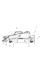
- FIG. 1 is a side view when the crane 1 is traveling.
- FIG. 2 is a side view of the crane 1 during work.
- the crane 1 is mainly composed of a traveling body 2 and a revolving body 3.
- the traveling body 2 includes a pair of left and right front tires 4 and a rear tire 5.
- the traveling body 2 includes an outrigger 6 that is grounded and stabilized when the lifting work is performed.
- the traveling body 2 includes an engine, a transmission, and the like in addition to the hydraulic actuator for driving them.
- the swivel body 3 is provided with a boom 7 so as to protrude forward from the center rear part thereof.
- the boom 7 can be raised and lowered by a raising and lowering cylinder 8 that is a hydraulic actuator, and can be expanded and contracted in multiple stages.
- a boom 7 is disposed in the left and right central portion, and a cabin 9 in which a driver's seat is installed is provided on the right side of the boom 7.
- the cabin 9 is arranged on the right side of the boom 7 will be described, but the cabin 9 can be provided on the left side of the boom 7.
- the revolving unit 3 includes a main winch 10 and a sub winch 11.
- the swivel body 3 includes a main hook 12 and a sub hook 13.
- the hoisting operation using the main hook 12 can be performed by winding or lowering the main winch 10.
- the hoisting operation using the subhook 13 can be performed by winding or lowering the subwinch 11.
- the hoisting cylinder 8 When the crane 1 is traveling, the hoisting cylinder 8 is contracted to bring the boom 7 into a state of being tilted forward, and the main hook 12 and the sub hook 13 are stored below the boom 7 (see FIG. 1). During the operation of the crane 1, the hoisting cylinder 8 is extended to bring the boom 7 up, and the storage of the main hook 12 and the sub hook 13 is released so that various operations can be performed (see FIG. 2).
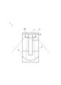
- FIG. 3 is a schematic diagram showing how obstacles are detected when the crane 1 is traveling.
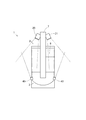
- FIG. 4 is a schematic diagram showing how obstacles are detected when the crane 1 is working.
- FIG. 5 is a control block diagram relating to obstacle detection around the crane 1.
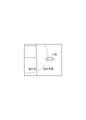
- FIG. 6 is a diagram illustrating a display example of the obstacle detection on the display device.
- FIG. 7 is an obstacle determination flow.
- a left camera 20 is provided at the left end of the tip of the boom 7 to obtain a left image of the traveling body 2 and the revolving body 3, and the traveling body 2 and the revolving body 3 are disposed at the right end.
- a right camera 21 is provided for acquiring a right-side video.
- the left camera 20 is a first obstacle sensor provided on the side opposite to the side where the cabin 9 is arranged in the revolving unit 3 (arranged toward the left side of the revolving unit 3), and its imaging range (detection) (Range) is arranged so as to be a range from the front end of the boom 7 to the left diagonally rearward direction.
- the right camera 21 is a second obstacle sensor provided on the same side as the cabin 9 (on the right side of the revolving structure 3), and the imaging range (detection range) is a range in which the boom 7 is directed diagonally right rearward. It is arranged to become.
- the left camera 20 detects the left side from the left and right center part of the crane 1
- the right camera 21 detects the right side from the left and right center part of the crane 1.
- the right camera 21 disposed on the opposite side of the driver seat serves as the first obstacle sensor
- the left camera 20 disposed on the same side as the driver seat is the first. It becomes the second obstacle sensor.
- the boom 7 is in a state of being turned down (see FIG. 1), so that the left camera 20 includes the front end and the left side of the traveling body 2 and the left side of the revolving body 3.
- the right camera 21 acquires images of the front end and the right side of the traveling body 2 and the right side of the revolving structure 3.
- the left camera 20 acquires images of the rear part and the left side of the revolving unit 3
- the right camera 21 acquires images of the rear and right sides of the revolving unit 3.
- the left camera 20 acquires images of the front end and the left side of the traveling body 2 and the left side of the revolving body 3 when the crane 1 travels.
- the left camera 20 disposed on the opposite side of the cabin 9 that is the driver's seat detects an obstacle on the left turn by detecting a situation on the left side that is difficult to visually confirm from the cabin 9 side. It is something to detect.
- the boom 7 is laid down forward, and its front end protrudes forward from the front end of the traveling body 2.
- the image of the left camera 20 disposed at the front end of the boom 7 is a photograph of the traveling body 2 and the revolving body 3 from the front, and it is easy to detect an obstacle present on the left side of the crane 1.
- the presence of an obstacle at the time of turning is detected by detecting the situation on the left side and the left rear side of the revolving structure 3 that is difficult to see from the cabin 9 with images. .
- the boom 7 is in an upright state, and the image acquired by the left camera 20 has an angle that looks down on the revolving unit 3. Thereby, it becomes easy to detect the obstacle which exists in the left side of the revolving structure 3.
- obstacle detection can be performed in a sufficient range both during traveling and during work. In particular, it is possible to prevent a collision with an obstacle at the time of turning by detecting the obstacle by capturing the rear side portion of the turning body 3 with the left camera 20.
- the present crane is characterized by a traveling body, a revolving body, a boom that is provided so as to protrude forward from the center rear portion of the revolving body, and that can be raised and lowered by a hydraulic actuator, and one side of the boom
- a crane having a driver's seat arranged on the side, provided with a first obstacle sensor for detecting an obstacle on the opposite side of the driver's seat from the front end of the boom diagonally rearward, and the first obstacle The sensor detects an approach of an obstacle to the front side portion of the traveling body during traveling, and detects an approach of the obstacle to the rear side portion of the revolving body during work.
- the first obstacle sensor directed obliquely backward from the tip of the boom that is, the obstacle sensor having a detection range directed from the front to the rear
- the vehicle travels from the front.
- the detection range directed from the front to the rear By detecting the sides of the vehicle and the swiveling body, the presence of obstacles when the traveling body changes its course is detected well. By detecting it, it is possible to satisfactorily detect the presence of an obstacle when the turning body turns.
- the crane 1 of this embodiment further includes a right camera 21.
- the right camera 21 acquires images of the front end of the traveling body 2 and the right side of the traveling body 2 and the revolving body 3 when the crane 1 travels. In other words, by detecting the right side situation that is difficult to visually confirm from the cabin 9 side, an entrainment of an obstacle during a right turn is detected.
- the camera angle at this time is an angle from the front similarly to the left camera 20, and it is easy to detect an obstacle present on the right side of the crane 1.
- the crane 1 when the crane 1 is working, it detects collisions with obstacles during turning by detecting the situation on the right side and right rear side of the revolving structure 3 that is difficult to see from the cabin 9 with images.
- the camera angle at this time is an angle from above like the left camera 20, and it is easy to detect an obstacle present around the revolving structure 3.
- the right camera 21 that can cover the situation on the same side as the cabin 9, particularly the blind spot of the cabin 9, obstacles in a more sufficient range both during traveling and during work. Detection is possible.
- a further feature of the crane is that a second obstacle sensor that detects an obstacle on the same side as the driver's seat from the tip of the boom toward the oblique rear side is provided, and the second obstacle is provided.
- the sensor detects an approach of an obstacle to the front side portion of the traveling body during traveling, and detects an approach of the obstacle to the rear side portion of the revolving body during work.
- the left camera 20 and the right camera 21 are electrically connected to the image processing controller 30, and transmit acquired video data to the image processing controller 30.
- the image processing controller 30 processes a video acquired by the left camera 20 and the right camera 21, and for example, identifies an obstacle such as a person / vehicle included in the video by image processing.
- the image processing controller 30 is electrically connected to the crane controller 31.
- the crane controller 31 controls the crane device.
- the crane controller 31 is electrically connected to the hoisting cylinder 8 and the PTO changeover switch 32, and obtains information on the attitude of the boom 7 (raising angle) and whether or not the crane device is driven.
- the crane controller 31 transmits the acquired information to the image processing controller 30.
- the image processing controller 30 is electrically connected to the display device 33.
- the image processing controller 30 generates a viewpoint conversion video (overhead video) based on the information transmitted from the crane controller 31.
- a viewpoint conversion video overhead video
- the captured normal video raw video
- the image processing controller 30 is electrically connected to the notification device 34.
- the image processing controller 30 recognizes the presence or absence of an obstacle based on the video transmitted from the left camera 20 and the right camera 21.
- the image processing controller 30 determines that there is an obstacle, the image processing controller 30 transmits an electrical signal to the notification device 34 to notify that there is an obstacle around the crane 1 using a buzzer, an indicator, or the like.
- the driver or a person who becomes an obstacle
- the image processing controller 30 further detects the approach of an obstacle, and transmits a control signal to the crane controller 31 to stop the crane device slowly or automatically.
- step S1 information on the status of the crane 1 is acquired. That is, the information regarding the position of the PTO changeover switch 32 is acquired (step S1), the information regarding the position of the hoisting cylinder 8 is acquired, and the hoisting angle of the boom 7 is obtained (step S2). At the same time, the position coordinates of the left camera 20 and the right camera 21 are acquired from the undulation angle of the boom 7 (step S3). By acquiring the position coordinates of the camera, conversion from the original image to the overhead image is possible.
- step S4 it is determined whether the crane 1 is in a traveling state or a working state.
- step S5 an image to be displayed on the display device 33 is selected from either a bird's-eye view image or a normal image (raw image taken by a camera). For example, when the crane 1 is in a traveling state, a normal image of the left camera 20 is displayed on the display device 33 when turning left, and when the crane 1 is in a working state, an overhead view image of the right camera 21 is displayed on the display device 33 when turning right. It is also possible to display it.
- step S6 An obstacle (person, car, etc.) is identified from the camera image acquired in this way (step S6).
- step S7 it is determined whether or not the identified obstacle is approaching the crane 1. If an obstacle is approaching (step S7: Y), the notification device 34 notifies that fact (step S8).
- step S9 when there is a possibility of an obstacle approaching and a collision with the crane 1 (step S9: Y), the operation of the crane 1 is gently and automatically stopped (step S10).
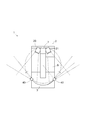
- FIG. 8 is a diagram illustrating how obstacles are detected during traveling of the crane 1 by the rear camera 40 provided at the rear of the revolving unit 3.
- FIG. 9 is a diagram showing how obstacles are detected during the operation of the crane 1.
- FIG. 10 is a diagram illustrating a display example of the obstacle detection on the display device.
- the crane 1 includes a rear camera for acquiring images of the side of the traveling body 2 and the revolving body 3 at both side ends of the revolving body 3.
- the rear camera 40 is a third obstacle sensor provided at the rear end of the revolving structure 3, and its imaging range (detection range) is directed obliquely forward from the rear end of the revolving structure 3 toward the outside of the body. It is arranged to be in the range.
- the rear camera 40 disposed at the rear right side end of the swing body 3 is located around the right side surface of the travel body 2 and the swing body 3 and at the rear left end of the swing body 3.
- the rear camera 40 arranged detects obstacles existing around the left side surfaces of the traveling body 2 and the revolving body 3.
- the rear camera 40 disposed at the rear right end of the swing body 3 detects an obstacle approaching the left rear portion of the swing body 3 when turning right
- the rear camera 40 disposed at the rear left end of the body 3 detects an obstacle approaching the right rear part of the swing body 3 when turning left.
- the rear camera 40 when working on the crane 1, the rear camera 40 is directed toward the tangential direction of a circle (a circle indicated by a one-dot chain line) serving as a turning locus at the time of turning of the rear side end of the turning body 3 serving as an installation location. Tilted. That is, during the operation of the crane 1, by changing the shooting direction so that the detection range of the rear camera 40 is the range in which the rear camera 40 is moved in the rear direction, the rear part of the revolving body 3 and the obstacle are brought into contact with each other. It is possible to detect more reliably.
- a circle a circle indicated by a one-dot chain line
- the shooting range of the rear camera 40 is set closer to the front, so that obstacles existing on both sides of the crane 1 can be easily detected when the course is changed when turning right or left.
- the boom 7 When starting the work with the crane 1, the boom 7 is raised after the outrigger 6 of the traveling body 2 is installed. That is, the fact that the outrigger 6 has been installed or the operation of the boom 7 has been started can be used as a trigger for starting work, and in response to this, the rear camera 40 can be tilted sideways to change the detection range.
- the rear camera 40 is electrically connected to the image processing controller 30 and transmits acquired video data to the image processing controller 30.
- the image processing controller 30 identifies obstacles such as a person and a vehicle included in the video photographed by the rear camera 40 by image processing, and transmits an electric signal to the crane controller 31, the display device 33, and the notification device 34 as appropriate.
- the display device 33 can also display a live image acquired by the rear camera 40. For example, as shown in FIG. 10, the turning radius of the swing body 3 (the rear end side portion of the swing body 3 is displayed on the overhead view image). Can be displayed in a superimposed manner.
- the crane 1 has a detection range directed obliquely forward from both sides of the rear end of the revolving structure 3.
- the rear camera 40 * 40 which has is provided.
- a further feature of the crane is that a third obstacle sensor that detects obstacles on both sides of the traveling body and the turning body from the rear end of the turning body obliquely forward is provided.
- the third obstacle sensor detects an approach of an obstacle to the front side portion of the traveling body during traveling, and detects an approach of the obstacle to the rear side portion of the revolving body during work.
- the third obstacle sensor having the detection range obliquely forward from the rear end of the revolving unit, that is, the detection range directed from the rear to the front, when traveling with the boom lying down, the vehicle travels from the rear.
- the detection range from the rear end of the revolving structure to the diagonally forward direction is set to a tangential direction of a circle serving as a turning locus of the rear end of the revolving structure. It is preferable to incline toward. Thus, by inclining toward the turning trajectory at the rear end of the revolving structure, collision with the revolving structure can be favorably avoided.
- the rear camera 40 is also preferably disposed on both the left and right sides of the revolving structure 3 in the same manner as the left camera 20 and the right camera 21, but only the side opposite to the side where the cabin 9 is provided, that is, only the left rear camera 40. It is good also as a structure which arrange
- the rear camera 40 since the rear camera 40 can detect obstacles in a sufficient range during traveling and work, as shown in FIG. 11, the rear camera 40 may be configured to monitor the surroundings using only the rear camera 40. good.
- the obstacle determination step in the surrounding monitoring at this time is the same as described above.
- the present crane is characterized by a traveling body, a revolving body, a boom that is provided so as to protrude forward from the center rear portion of the revolving body, and that can be raised and lowered by a hydraulic actuator, and one side of the boom
- a crane having a driver seat arranged on the side, provided with a third obstacle sensor for detecting obstacles on both sides of the traveling body and the swivel body obliquely forward from the rear end of the swivel body, The third obstacle sensor detects an approach of an obstacle to the front side portion of the traveling body during traveling, and detects an approach of the obstacle to the rear side portion of the revolving body during work.
- the third obstacle sensor having a detection range obliquely forward from the rear end of the swinging body, the side of the traveling body and the swinging body is detected from the rear when traveling with the boom lying down. Therefore, the presence of obstacles when the turning body turns by detecting the side of the turning body during work with the boom standing up is well detected by detecting the obstacle when the traveling body changes course Can be detected satisfactorily.
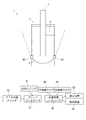
- FIG. 12 is a diagram showing how obstacles of the crane 1 are detected by the front cameras 50 provided on both sides of the front part of the traveling body 2.
- the front camera 50 is provided on both the left and right sides of the front end of the traveling body 2.
- the front camera 50 is disposed at the front end of the traveling body 2 obliquely rearward on the outer side of the body.
- the front camera 50 is a photographing device that acquires images of the side of the traveling body 2 and the revolving body 3 and has a photographing range (detection range) from the front to the rear.
- the front camera 50 can be provided, for example, in the vicinity of a side mirror provided at the front end of the traveling body 2.
- the left and right front cameras 50 arranged in this way detect obstacles around the left and right sides of the traveling body 2 and the revolving body 3 when the crane 1 is traveling and working.
- the obstacle determination step in the surrounding monitoring at this time is the same as described above.
- the front camera 50 is preferably arranged on both the left and right sides of the revolving structure 3 as with the left camera 20 and the right camera 21, but only the side opposite to the side where the cabin 9 is provided, that is, the left front camera 50 only. It is good also as a structure which arrange
- each camera as an obstacle sensor is arranged at the side end of the traveling body 2 or the revolving body 3.
- a wide-angle camera is provided at the left and right central part of the revolving body 3 to travel. You may make it include the monitoring area
- a camera which is a photographing device is adopted as the obstacle sensor, but a sensor generally used as an obstacle sensor such as a distance sensor or an infrared sensor having a similar detection range is substituted. It is also possible to adopt a configuration in which the approach of an obstacle is detected and notified.
- the present invention can be used for a crane.
Landscapes
- Engineering & Computer Science (AREA)
- Mechanical Engineering (AREA)
- Multimedia (AREA)
- Mining & Mineral Resources (AREA)
- Civil Engineering (AREA)
- General Engineering & Computer Science (AREA)
- Structural Engineering (AREA)
- Automation & Control Theory (AREA)
- Jib Cranes (AREA)
- Closed-Circuit Television Systems (AREA)
- Component Parts Of Construction Machinery (AREA)
Abstract
クレーンの走行時と作業時の両方において、十分な範囲で障害物検知を可能とする技術を提供する。 クレーンにおいて、走行時、走行体の前側部に対する障害物の接近を検知し、かつ、作業時、旋回体の後側部に対する障害物の接近を検知する障害物センサを設けた。第一実施形態においては、前記障害物センサは、前方から後方に向けた検知範囲を有する。第二実施形態においては、前記障害物センサは、後方から前方に向けた検知範囲を有する。
Description
本発明は、障害物センサによって走行時及び作業時に障害物を検知する技術に関する。
特許文献1には、油圧ショベルの車両周辺を監視するために、上部旋回体に俯瞰画像を形成する第一のカメラと、上部旋回体の後端から側部へのコーナ部を視野範囲に含み、上部旋回体の旋回に追従して回動することでスルー画像を撮影する第二のカメラとを備え、ディスプレイに俯瞰画像とスルー画像を表示する構成が開示されている。
クレーンにおいて、特許文献1に記載の技術と同様に第一のカメラと第二のカメラを設けることで、走行時の障害物を検知することはできるが、クレーン作業時の姿勢は、走行時の姿勢と大きく異なり、監視領域や障害物との衝突パターンも異なるため、十分な作業範囲の検知ができないという課題が残る。例えば、走行時は、右左折時の巻き込みを防止すべく、監視対象や障害物との衝突パターンを考慮する必要があり、作業時は、左右旋回時の衝突を防止すべく、監視対象や障害物との衝突パターンを考慮する必要がある。
本発明は、クレーンの走行時と作業時の両方において、十分な範囲で障害物検知を可能とする技術を提供することを課題とする。
走行時、走行体の前側部に対する障害物の接近を検知し、かつ、作業時、旋回体の後側部に対する障害物の接近を検知する障害物センサを設けた。
前記障害物センサは、前方から後方に向けた検知範囲を有する。
前記障害物センサは、後方から前方に向けた検知範囲を有する。
本発明によれば、クレーンの走行時と作業時の両方において、十分な範囲で障害物検知を実行することができる。
図1及び図2を参照して、クレーンの全体構成について説明する。図1は、クレーン1の走行時の側面図である。図2は、クレーン1の作業時の側面図である。
クレーン1は、主に走行体2と旋回体3で構成されている。
走行体2は、左右一対のフロントタイヤ4とリヤタイヤ5を備えている。走行体2は、吊上作業を行う際に接地させて安定を図るアウトリガ6を備えている。走行体2は、これらを駆動するための油圧アクチュエータに加え、エンジンやトランスミッションなどを備えている。
旋回体3は、その中央後部から前方へ突き出すようにブーム7を備えている。ブーム7は、油圧アクチュエータである起伏シリンダ8によって起伏自在であり、かつ多段階に伸縮自在となっている。また、左右中央部にブーム7が配置され、ブーム7の右方に運転席が内装されるキャビン9が設けられる。以下の説明では、ブーム7の右方にキャビン9が配置される実施形態について説明するが、ブーム7の左方にキャビン9を設けることも可能である。
旋回体3は、メインウインチ10及びサブウインチ11を備えている。旋回体3は、メインフック12及びサブフック13を備えている。メインウインチ10を巻き上げ又は巻き下げることでメインフック12を用いた吊上作業を実施可能である。サブウインチ11を巻き上げ又は巻き下げることでサブフック13を用いた吊上作業を実施可能である。
クレーン1の走行時には、起伏シリンダ8を収縮させてブーム7を前方に倒伏させた状態とし、メインフック12及びサブフック13をブーム7の下方に格納する(図1参照)。クレーン1の作業時には、起伏シリンダ8を伸長させてブーム7を上方に起立させた状態とし、メインフック12及びサブフック13の格納を解除し、各種作業を実施可能とする(図2参照)。
図3から図7を参照して、クレーン周囲の障害物検知について説明する。図3は、クレーン1の走行時の障害物検知の様子を示す模式図である。図4は、クレーン1の作業時の障害物検知の様子を示す模式図である。図5は、クレーン1の周囲の障害物検知に関する制御ブロック図である。図6は、障害物検知の表示装置への表示例を示す図である。図7は、障害物判定のフローである。
図3及び図4に示すように、ブーム7の先端の左端に走行体2及び旋回体3の左方の映像を取得するための左カメラ20が設けられ、右端に走行体2及び旋回体3の右方の映像を取得するための右カメラ21が設けられている。
左カメラ20は、旋回体3においてキャビン9が配置される側と反対側に設けられた(旋回体3の左側に向けて配置される)第一の障害物センサであり、その撮影範囲(検知範囲)がブーム7の先端から左斜め後方に向けた範囲となるように配置されている。右カメラ21は、キャビン9と同じ側(旋回体3の右側)に設けられた第二の障害物センサであり、その撮影範囲(検知範囲)がブーム7の先端から右斜め後方に向けた範囲となるように配置されている。このように、左カメラ20はクレーン1の左右中央部から左側を、右カメラ21はクレーン1の左右中央部から右側をそれぞれ検知している。
なお、キャビン9をブーム7の左方に設ける場合は、運転席と反対側に配置される右カメラ21が第一の障害物センサとなり、運転席と同じ側に配置される左カメラ20が第二の障害物センサとなる。
図3に示すように、クレーン1の走行時は、ブーム7が伏せられた状態(図1参照)であることから、左カメラ20は、走行体2の前端と左側方及び旋回体3の左側方の映像を取得し、右カメラ21は、走行体2の前端と右側方及び旋回体3の右側方の映像を取得する。図4に示すように、クレーン1の作業時は、ブーム7が起こされた状態(図2参照)であることから、左カメラ20は、旋回体3の後部と左側方の映像を取得し、右カメラ21は、旋回体3の後部と右側方の映像を取得する。
左カメラ20は、クレーン1の走行時は、走行体2の前端と左側方及び旋回体3の左側方の映像を取得する。つまり、運転席であるキャビン9と反対側に配置される左カメラ20は、キャビン9側から目視にて確認し難い左方の状況を映像によって検知することで、左折時の障害物の存在を検知するものである。このとき、ブーム7は、前方に倒伏されており、その前端は走行体2の前端よりも前方に突出した状態となっている。これにより、ブーム7の前端に配置される左カメラ20の映像は、走行体2及び旋回体3を前方から撮影したものとなり、クレーン1の左側方に存在する障害物を検知し易くなる。特に、左カメラ20によって走行体2の前側部を捉えて障害物を検知することで、進路変更時の障害物の巻き込みを防止することができる。
また、クレーン1の作業時も同様に、キャビン9からは目視し難い旋回体3の左側方及び左後方の状況を映像によって検知することで、旋回時の障害物の存在を検知するものである。作業時には、ブーム7は上方に起立した状態となり、左カメラ20によって取得される映像は、旋回体3を見下ろすようなアングルとなる。これにより、旋回体3の左側方に存在する障害物を検知し易くなる。このように、キャビン9と逆側の状況を確認することができる左カメラ20を配置することで、走行時及び作業時の両方において十分な範囲での障害物検知が可能となる。特に、左カメラ20によって旋回体3の後側部を捉えて障害物を検知することで、旋回時の障害物との衝突を防止することができる。
以上のように、第一の障害物センサとしての左カメラ20によって取得される映像を確認することによって、走行時は左折時の巻き込みによる障害物との衝突を回避することが可能となり、作業時は右旋回に際する左後部の障害物との衝突を回避することが可能となる。つまり、運転席と反対側にあり視界が制限されている左側方の障害物検知において、一台の障害物センサによって走行時と作業時の両方における障害物との衝突を回避することが可能である。
以上のように、本クレーンの特徴は、走行体と、旋回体と、前記旋回体の中央後部から前方へ突き出すように設けられ、油圧アクチュエータによって起伏自在に設けられるブームと、前記ブームの一側方に配置される運転席とを備えるクレーンにおいて、前記運転席と反対側の障害物を、ブームの先端から斜め後方に向けて検知する第一の障害物センサを設け、前記第一の障害物センサは、走行時、前記走行体の前側部に対する障害物の接近を検知し、作業時、前記旋回体の後側部に対する障害物の接近を検知するものである。
このように、ブーム先端から斜め後方に向けた第一の障害物センサ、つまり、前方から後方に向けた検知範囲を有する障害物センサによれば、ブームを倒伏させた走行時は、前方から走行体及び旋回体の側方を検知することで走行体が進路変更する際の障害物の存在を良好に検知し、ブームを起立させた作業時は、上方から走行体及び旋回体の側方を検知することで旋回体が旋回する際の障害物の存在を良好に検知することができる。
本実施形態のクレーン1は、さらに右カメラ21を備えている。右カメラ21は、クレーン1の走行時は、走行体2の前端と走行体2及び旋回体3の右側方の映像を取得する。つまり、キャビン9側から目視にて確認し難い右方の状況を映像によって検知することで、右折時の障害物の巻き込みを検知するものである。このときのカメラアングルは、左カメラ20と同様に前方からのアングルであり、クレーン1の右側方に存在する障害物を検知し易い。
また、クレーン1の作業時には、キャビン9からは目視し難い旋回体3の右側方及び右後方の状況を映像によって検知することで、旋回時の障害物との衝突を検知するものである。このときのカメラアングルは、左カメラ20と同様に上方からのアングルであり、旋回体3の周囲に存在する障害物を検知し易い。このように、キャビン9と同じ側の状況、特にキャビン9の死角をカバーすることができる右カメラ21を併せて配置することで、走行時及び作業時の両方においてより十分な範囲での障害物検知が可能となっている。
以上のように、第二の障害物センサとしての右カメラ21によって取得される映像を確認することによって、走行時は右折時の巻き込みによる障害物との衝突を回避することが可能となり、作業時は左旋回に際する右後部の障害物との衝突を回避することが可能となる。つまり、運転席と同じ側の右側方の障害物検知において、一台の障害物センサによって走行時と作業時の両方における障害物との衝突を回避することが可能である。
以上のように、本クレーンの更なる特徴は、前記運転席と同じ側の障害物を、ブームの先端から斜め後方に向けて検知する第二の障害物センサを設け、前記第二の障害物センサは、走行時、前記走行体の前側部に対する障害物の接近を検知し、作業時、前記旋回体の後側部に対する障害物の接近を検知するものである。このように、第一の障害物センサの反対側の障害物を検知する第二の障害物センサを、前方から後方に向けた検知範囲を有する障害物センサとして設けることで、クレーンの周囲の障害物を二つの障害物センサで検知することができる。
図5に示すように、左カメラ20及び右カメラ21は、画像処理コントローラ30と電気的に接続されており、それぞれ取得した映像データを画像処理コントローラ30に送信している。画像処理コントローラ30は、左カメラ20と右カメラ21とによって取得される映像を処理するものであり、例えば、映像内に含まれる人物・車両等の障害物を画像処理によって識別するものである。
画像処理コントローラ30は、クレーンコントローラ31と電気的に接続されている。クレーンコントローラ31は、クレーン装置を制御するものである。クレーンコントローラ31は、起伏シリンダ8及びPTO切替スイッチ32と電気的に接続されており、ブーム7の姿勢(起伏角度)、及びクレーン装置の駆動の有無に関する情報を取得している。クレーンコントローラ31は、取得したこれらの情報を画像処理コントローラ30に送信する。
画像処理コントローラ30は、表示装置33と電気的に接続されている。画像処理コントローラ30では、クレーンコントローラ31から送信された情報に基づいて、視点変換映像(俯瞰映像)が生成される。表示装置33では、画像処理コントローラ30によって生成された俯瞰映像、又は、撮影された通常映像(生映像)の何れか、若しくはそれら両方が表示される。また、表示装置33に表示する画像を選択することも可能である。すなわち、表示装置33を操作することで、図6に示すように、(1)通常映像、(2)俯瞰映像、若しくは(3)これら両方、から選択することができる。なお、表示装置33に左カメラ20の映像と右カメラ21の映像を同時に表示しても良い。
また、画像処理コントローラ30は、報知装置34と電気的に接続されている。画像処理コントローラ30では、左カメラ20及び右カメラ21から送信された映像に基づいて、障害物の有無が認識される。画像処理コントローラ30は、障害物が存在すると判定すると、報知装置34に電気信号を送信して、ブザー、インジケータ等によってクレーン1の周囲に障害物が存在する旨を報知する。報知装置34によって報知することによって、運転者(又は障害物となる人物)に障害物の接近を確実に知らせることができ、障害物との衝突を回避し易くなる。
画像処理コントローラ30は、さらに、障害物の接近を検知して、クレーンコントローラ31にクレーン装置を緩停止や自動停止する旨の制御信号を送信する。
次に、図7を用いて、画像処理コントローラ30において実行される障害物判定ステップについて説明する。
まず、クレーン1の状況に関する情報を取得する。すなわち、PTO切替スイッチ32のポジションに関する情報を取得し(ステップS1)、起伏シリンダ8のポジションに関する情報を取得してブーム7の起伏角度を取得する(ステップS2)。これとともに、ブーム7の起伏角度から左カメラ20及び右カメラ21の位置座標を取得する(ステップS3)。カメラの位置座標を取得することで、元画像から俯瞰画像への変換が可能となる。
そして、ステップS4で、クレーン1が走行状態、又は作業状態の何れであるかを判定する。次に、ステップS5で、表示装置33に表示する映像を俯瞰映像又は通常映像(カメラによって撮影された生映像)の何れかから選択する。例えば、クレーン1が走行状態の場合、左折時には左カメラ20の通常映像を表示装置33に表示したり、クレーン1が作業状態の場合、右旋回時には右カメラ21の俯瞰映像を表示装置33に表示したりすることも可能である。
このように取得されたカメラ映像から障害物(人物、車等)を識別する(ステップS6)。ステップS7において、識別された障害物がクレーン1に接近しているか否かが判定される。障害物が接近している場合(ステップS7:Y)は、報知装置34によってその旨が報知される(ステップS8)。
さらに障害物が接近し、クレーン1との衝突の可能性がある場合(ステップS9:Y)は、クレーン1の作動を緩やかに自動停止する(ステップS10)。
次に、図8から図10を参照して、クレーン周囲の障害物検知の別実施形態について説明する。図8は、旋回体3の後部に設けた後部カメラ40によるクレーン1の走行時の障害物検知の様子を示す図である。図9は、同じくクレーン1の作業時の障害物検知の様子を示す図である。図10は、障害物検知の表示装置への表示例を示す図である。
図8に示すように、クレーン1には、左カメラ20と右カメラ21に加えて、旋回体3の後部両側端に走行体2及び旋回体3の側方の映像を取得するための後部カメラ40が設けられている。後部カメラ40は、旋回体3の後端に設けられた第三の障害物センサであり、その撮影範囲(検知範囲)が旋回体3の後部の側端から機体外側に向けて斜め前方に向けた範囲となるように配置されている。
図8に示すように、クレーン1の走行時、旋回体3の後部右側端に配置される後部カメラ40は、走行体2及び旋回体3の右側面の周辺、旋回体3の後部左側端に配置される後部カメラ40は、走行体2及び旋回体3の左側面の周辺に存在する障害物をそれぞれ検知している。図9に示すように、クレーン1の作業時、旋回体3の後部右側端に配置される後部カメラ40は、右旋回時の旋回体3の左後部に接近する障害物を検知し、旋回体3の後部左側端に配置される後部カメラ40は、左旋回時の旋回体3の右後部に接近する障害物を検知している。
図9に示すように、クレーン1の作業時、後部カメラ40は、設置箇所となる旋回体3の後部側端の旋回時の旋回軌跡となる円(一点鎖線で示す円)の接線方向に向けて傾けられる。つまり、クレーン1の作業時には、後部カメラ40による検知範囲を旋回体3の後部の移動方向に向けた範囲とするように撮影方向を変更することで、旋回体3の後部と障害物の接触をより確実に検知することが可能である。
以上のように、クレーン1の走行時には、後部カメラ40の撮影範囲を前方寄りに設定することで右折時や左折時等の進路変更時にクレーン1の両側方に存在する障害物を検知し易くなり、クレーン1の作業時には、後部カメラ40の撮影範囲を側方寄りに設定することで旋回体3の旋回範囲に位置する障害物を検知し易くなる。また、旋回時には、旋回方向と同じ側の後部カメラ40によってブーム7の移動先に存在する障害物を早いタイミングで検知することが可能である。
クレーン1による作業を開始する際は、走行体2のアウトリガ6を設置した上で、ブーム7を起立させることとなる。つまり、アウトリガ6を設置したこと又はブーム7の操作を開始したことを作業開始のトリガーとして利用し、それを受けて後部カメラ40を側方に向けて傾けて検知範囲を変更することができる。
後部カメラ40は、それぞれ画像処理コントローラ30と電気的に接続されており、取得した映像データを画像処理コントローラ30に送信している。画像処理コントローラ30は、後部カメラ40によって撮影された映像内に含まれる人物・車両等の障害物を画像処理によって識別し、適宜クレーンコントローラ31、表示装置33、報知装置34に電気信号を送信する。表示装置33では、後部カメラ40によって取得される生映像を表示することも可能であるし、例えば、図10に示すように俯瞰画像に旋回体3の旋回半径(旋回体3の後端側部の旋回軌跡)を重畳して表示することも可能である。
以上のように、クレーン1は、ブーム7の先端から斜め後方に向けた検知範囲を有する左カメラ20・右カメラ21に加えて、旋回体3の後端両側から斜め前方に向けた検知範囲を有する後部カメラ40・40を備えている。このように、前方から後方に向けた検知範囲を有する障害物センサによる前方からの周囲監視と、後方から前方に向けた検知範囲を有する障害物センサによる後方からの周囲監視を同時に行うことで、より確実な障害物の検知が可能となり、クレーン1と障害物の接触をさらに回避し易くなる。
以上のように、本クレーンの更なる特徴は、前記走行体及び旋回体の両側方の障害物を、旋回体の後端から斜め前方に向けて検知する第三の障害物センサを設け、前記第三の障害物センサは、走行時、前記走行体の前側部に対する障害物の接近を検知し、作業時、前記旋回体の後側部に対する障害物の接近を検知するものである。
このように、旋回体後端から斜め前方に向けた検知範囲、つまり後方から前方に向けた検知範囲を有する第三の障害物センサによれば、ブームを倒伏させた走行時は、後方から走行体及び旋回体の側方を検知することで走行体が進路変更する際の障害物の存在を良好に検知し、ブームを起立させた作業時は、旋回体の側方を検知することで旋回体が旋回する際の障害物の存在を良好に検知することができる。
さらに、前記第三の障害物センサは、作業を開始する際に、前記旋回体の後端から斜め前方に向けた検知範囲を、前記旋回体の後側端の旋回軌跡となる円の接線方向に向けて傾けることが好ましい。このように、旋回体の後端の旋回軌跡に向けて傾斜させることで、旋回体との衝突を良好に回避することができる。
なお、後部カメラ40についても、左カメラ20及び右カメラ21と同様に旋回体3の左右両側に配置されることが好ましいが、キャビン9が設けられる側と反対側、つまり左後部カメラ40のみを配置し、キャビン9から目視し難い領域を監視する構成としても良い。
上述のように、後部カメラ40は、走行時及び作業時に十分な範囲での障害物検知を可能であるため、図11に示すように、後部カメラ40のみを用いて周囲監視を行う構成としても良い。この際の周囲監視における障害物判定ステップは上述と同様である。
以上のように、本クレーンの特徴は、走行体と、旋回体と、前記旋回体の中央後部から前方へ突き出すように設けられ、油圧アクチュエータによって起伏自在に設けられるブームと、前記ブームの一側方に配置される運転席とを備えるクレーンにおいて、前記走行体及び旋回体の両側方の障害物を、旋回体の後端から斜め前方に向けて検知する第三の障害物センサを設け、前記第三の障害物センサは、走行時、前記走行体の前側部に対する障害物の接近を検知し、作業時、前記旋回体の後側部に対する障害物の接近を検知するものである。
このように、旋回体後端から斜め前方に向けた検知範囲を有する第三の障害物センサによれば、ブームを倒伏させた走行時は、後方から走行体及び旋回体の側方を検知することで走行体が進路変更する際の障害物の存在を良好に検知し、ブームを起立させた作業時は、旋回体の側方を検知することで旋回体が旋回する際の障害物の存在を良好に検知することができる。
次に、図12を参照して、前方から後方に向けた検知範囲を有する障害物センサを用いたクレーン周囲の障害物検知の他の実施形態について説明する。図12は、走行体2の前部両側に設けた前部カメラ50によるクレーン1の障害物検知の様子を示す図である。
図12に示すように、前部カメラ50は、走行体2の前端の左右両側に設けられる。前部カメラ50は、走行体2の前端において、機体外方側に斜め後方に向けて配置されている。前部カメラ50は、走行体2及び旋回体3の側方の映像を取得する撮影装置であり、前方から後方に向けた撮影範囲(検知範囲)を有する。前部カメラ50は、例えば走行体2の前端に設けられるサイドミラーの近傍に設けることが可能である。
このように配置される左右の前部カメラ50によって、クレーン1の走行時及び作業時に、走行体2及び旋回体3の左右両側面の周囲に存在する障害物をそれぞれ検知している。この際の周囲監視における障害物判定ステップは上述と同様である。また、前部カメラ50についても、左カメラ20及び右カメラ21と同様に旋回体3の左右両側に配置されることが好ましいが、キャビン9が設けられる側と反対側、つまり左前部カメラ50のみを配置し、キャビン9から目視し難い領域を監視する構成としても良い。
また、上述の実施形態では、障害物センサとしての各カメラを走行体2又は旋回体3の側端部に配置しているが、例えば広角のカメラを旋回体3の左右中央部に設け、走行体2及び旋回体3の両側方における監視領域を検知範囲に含めるようにしても良い。
以上の実施形態では、障害物センサとして撮影装置であるカメラを採用しているが、同様の検知範囲を有する距離センサ、赤外線センサ等、一般的に障害物センサとして用いられているセンサを代用し、障害物の接近を検知して報知する構成とすることも可能である。
本発明は、クレーンに利用可能である。
1:クレーン、2:走行体、3:旋回体、7:ブーム、9:キャビン、20:左カメラ(障害物センサ)、21:右カメラ(障害物センサ)、30:画像処理コントローラ、31:クレーンコントローラ、33:表示装置、34:報知装置、40:後部カメラ(障害物センサ)、50:前部カメラ(障害物センサ)
Claims (3)
- 走行時、走行体の前側部に対する障害物の接近を検知し、かつ、作業時、旋回体の後側部に対する障害物の接近を検知する障害物センサを設けたことを特徴とするクレーン。
- 前記障害物センサは、前方から後方に向けた検知範囲を有する請求項1に記載のクレーン。
- 前記障害物センサは、後方から前方に向けた検知範囲を有する請求項1に記載のクレーン。
Priority Applications (3)
| Application Number | Priority Date | Filing Date | Title |
|---|---|---|---|
| CN201780074417.4A CN110088035B (zh) | 2016-12-09 | 2017-12-08 | 起重机 |
| EP17878234.8A EP3553017B1 (en) | 2016-12-09 | 2017-12-08 | Crane |
| US16/465,001 US10618780B2 (en) | 2016-12-09 | 2017-12-08 | Crane |
Applications Claiming Priority (2)
| Application Number | Priority Date | Filing Date | Title |
|---|---|---|---|
| JP2016-239900 | 2016-12-09 | ||
| JP2016239900A JP6390065B2 (ja) | 2016-12-09 | 2016-12-09 | クレーン |
Publications (1)
| Publication Number | Publication Date |
|---|---|
| WO2018105741A1 true WO2018105741A1 (ja) | 2018-06-14 |
Family
ID=62491922
Family Applications (1)
| Application Number | Title | Priority Date | Filing Date |
|---|---|---|---|
| PCT/JP2017/044234 WO2018105741A1 (ja) | 2016-12-09 | 2017-12-08 | クレーン |
Country Status (5)
| Country | Link |
|---|---|
| US (1) | US10618780B2 (ja) |
| EP (1) | EP3553017B1 (ja) |
| JP (1) | JP6390065B2 (ja) |
| CN (1) | CN110088035B (ja) |
| WO (1) | WO2018105741A1 (ja) |
Cited By (2)
| Publication number | Priority date | Publication date | Assignee | Title |
|---|---|---|---|---|
| JP2020100310A (ja) * | 2018-12-21 | 2020-07-02 | 株式会社タダノ | 作業車 |
| EP3943439A4 (en) * | 2019-05-17 | 2022-07-20 | Kobelco Construction Machinery Co., Ltd. | CONSTRUCTION MACHINE AND CONSTRUCTION MACHINE CONTROL METHOD |
Families Citing this family (13)
| Publication number | Priority date | Publication date | Assignee | Title |
|---|---|---|---|---|
| US10822208B2 (en) * | 2014-12-23 | 2020-11-03 | Manitowoc Crane Companies, Llc | Crane 3D workspace spatial techniques for crane operation in proximity of obstacles |
| WO2019152111A1 (en) * | 2018-02-02 | 2019-08-08 | Tulsa Winch, Inc. | Work area monitoring system for lifting machines |
| JP7138007B2 (ja) * | 2018-10-10 | 2022-09-15 | 東洋建設株式会社 | 施工現場の監視システム及び監視方法 |
| JP7358070B2 (ja) | 2019-04-26 | 2023-10-10 | 住友建機株式会社 | ショベル |
| JP7379866B2 (ja) | 2019-05-21 | 2023-11-15 | コベルコ建機株式会社 | 作業機械 |
| CN111170161B (zh) * | 2019-12-28 | 2021-06-18 | 贵州云腾未来科技有限公司 | 基于场景检测的模式设定系统 |
| JP2021174054A (ja) * | 2020-04-20 | 2021-11-01 | 株式会社小松製作所 | 作業機械の障害物報知システムおよび作業機械の障害物報知方法 |
| JP7484432B2 (ja) | 2020-06-01 | 2024-05-16 | 株式会社タダノ | クレーン走行支援装置 |
| CN112019752A (zh) * | 2020-09-11 | 2020-12-01 | 三一汽车起重机械有限公司 | 一种全景监控方法、全景监控系统及起重机 |
| JP2022048490A (ja) * | 2020-09-15 | 2022-03-28 | 株式会社小松製作所 | 作業車両 |
| JP7435819B2 (ja) | 2020-10-30 | 2024-02-21 | 株式会社タダノ | クレーン |
| CN112607602A (zh) * | 2020-12-24 | 2021-04-06 | 郝明钰 | 一种塔机吊钩视频跟踪装置 |
| JP2023110512A (ja) * | 2022-01-28 | 2023-08-09 | 株式会社小松製作所 | 作業機械、作業機械を制御するための方法、及び、作業機械の制御システム |
Citations (7)
| Publication number | Priority date | Publication date | Assignee | Title |
|---|---|---|---|---|
| JPH0948584A (ja) * | 1995-08-08 | 1997-02-18 | Komatsu Ltd | 移動式クレーンの吊り荷及び走行監視装置のカメラ装置 |
| JP2000247572A (ja) * | 1999-02-25 | 2000-09-12 | Yutani Heavy Ind Ltd | ホイール式作業機械 |
| JP2002020074A (ja) * | 2000-07-04 | 2002-01-23 | Tadano Ltd | クレーン車の前方視認装置 |
| JP2004345825A (ja) * | 2003-05-23 | 2004-12-09 | Kobelco Contstruction Machinery Ltd | 自走式作業機械 |
| EP2511677A1 (en) * | 2011-04-12 | 2012-10-17 | Tamtron Oy | Monitoring system for a material transfer vehicle |
| JP2016013888A (ja) * | 2014-07-01 | 2016-01-28 | 株式会社タダノ | クレーン車の障害物報知システム |
| JP2016030891A (ja) | 2014-07-25 | 2016-03-07 | 日立建機株式会社 | 旋回式作業機の周囲表示装置 |
Family Cites Families (13)
| Publication number | Priority date | Publication date | Assignee | Title |
|---|---|---|---|---|
| JPS6156385U (ja) * | 1984-09-14 | 1986-04-15 | ||
| JP2521244Y2 (ja) * | 1990-01-17 | 1996-12-25 | 株式会社タダノ | クレーン車の側方視認装置 |
| JP3265336B2 (ja) * | 1993-08-06 | 2002-03-11 | 株式会社タダノ | 吊荷監視カメラつきクレーン車 |
| US6549139B2 (en) * | 1997-02-27 | 2003-04-15 | Jack B. Shaw, Jr. | Crane safety device and methods |
| US7116356B2 (en) * | 2001-09-13 | 2006-10-03 | Peeples Jason W | Vertically self-aligning camera mount apparatus |
| CN2776943Y (zh) * | 2005-03-29 | 2006-05-03 | 徐州重型机械有限公司 | 起重机视野拓展装置 |
| JP2010241548A (ja) * | 2009-04-03 | 2010-10-28 | Kansai Electric Power Co Inc:The | クレーンの安全確認装置 |
| JP6256874B2 (ja) * | 2014-02-14 | 2018-01-10 | 株式会社フジタ | 建設機械用俯瞰画像表示装置 |
| JP6342705B2 (ja) * | 2014-05-12 | 2018-06-13 | 古河ユニック株式会社 | 作業機用ブーム衝突回避装置 |
| JP6389087B2 (ja) * | 2014-09-11 | 2018-09-12 | 古河ユニック株式会社 | 作業機用ブーム衝突回避装置 |
| JP2016094693A (ja) * | 2014-11-11 | 2016-05-26 | ヤンマー株式会社 | 作業車両 |
| JP2016183033A (ja) * | 2015-03-26 | 2016-10-20 | 株式会社タダノ | クレーン車の死角映像表示システム |
| CN204917777U (zh) * | 2015-07-10 | 2015-12-30 | 新乡新起机器设备有限公司 | 一种起重机监控垂直吊装机构 |
-
2016
- 2016-12-09 JP JP2016239900A patent/JP6390065B2/ja active Active
-
2017
- 2017-12-08 EP EP17878234.8A patent/EP3553017B1/en active Active
- 2017-12-08 WO PCT/JP2017/044234 patent/WO2018105741A1/ja unknown
- 2017-12-08 CN CN201780074417.4A patent/CN110088035B/zh active Active
- 2017-12-08 US US16/465,001 patent/US10618780B2/en active Active
Patent Citations (7)
| Publication number | Priority date | Publication date | Assignee | Title |
|---|---|---|---|---|
| JPH0948584A (ja) * | 1995-08-08 | 1997-02-18 | Komatsu Ltd | 移動式クレーンの吊り荷及び走行監視装置のカメラ装置 |
| JP2000247572A (ja) * | 1999-02-25 | 2000-09-12 | Yutani Heavy Ind Ltd | ホイール式作業機械 |
| JP2002020074A (ja) * | 2000-07-04 | 2002-01-23 | Tadano Ltd | クレーン車の前方視認装置 |
| JP2004345825A (ja) * | 2003-05-23 | 2004-12-09 | Kobelco Contstruction Machinery Ltd | 自走式作業機械 |
| EP2511677A1 (en) * | 2011-04-12 | 2012-10-17 | Tamtron Oy | Monitoring system for a material transfer vehicle |
| JP2016013888A (ja) * | 2014-07-01 | 2016-01-28 | 株式会社タダノ | クレーン車の障害物報知システム |
| JP2016030891A (ja) | 2014-07-25 | 2016-03-07 | 日立建機株式会社 | 旋回式作業機の周囲表示装置 |
Non-Patent Citations (1)
| Title |
|---|
| See also references of EP3553017A4 |
Cited By (6)
| Publication number | Priority date | Publication date | Assignee | Title |
|---|---|---|---|---|
| JP2020100310A (ja) * | 2018-12-21 | 2020-07-02 | 株式会社タダノ | 作業車 |
| US20220001844A1 (en) * | 2018-12-21 | 2022-01-06 | Tadano Ltd. | Work vehicle |
| EP3868603A4 (en) * | 2018-12-21 | 2022-08-17 | Tadano Ltd. | COMMERCIAL VEHICLE |
| JP7220358B2 (ja) | 2018-12-21 | 2023-02-10 | 株式会社タダノ | 作業車 |
| JP7388526B2 (ja) | 2018-12-21 | 2023-11-29 | 株式会社タダノ | 作業車 |
| EP3943439A4 (en) * | 2019-05-17 | 2022-07-20 | Kobelco Construction Machinery Co., Ltd. | CONSTRUCTION MACHINE AND CONSTRUCTION MACHINE CONTROL METHOD |
Also Published As
| Publication number | Publication date |
|---|---|
| US20190292024A1 (en) | 2019-09-26 |
| EP3553017A4 (en) | 2020-10-28 |
| CN110088035A (zh) | 2019-08-02 |
| US10618780B2 (en) | 2020-04-14 |
| EP3553017B1 (en) | 2023-04-26 |
| EP3553017A1 (en) | 2019-10-16 |
| JP2018095359A (ja) | 2018-06-21 |
| CN110088035B (zh) | 2022-02-08 |
| JP6390065B2 (ja) | 2018-09-19 |
Similar Documents
| Publication | Publication Date | Title |
|---|---|---|
| JP6390065B2 (ja) | クレーン | |
| JP5722127B2 (ja) | 作業車両の周辺監視装置 | |
| JP4694032B2 (ja) | 作業機械の表示装置 | |
| JP6134668B2 (ja) | 作業車両の障害物検知装置 | |
| JP6507501B2 (ja) | クレーン車の障害物報知システム | |
| KR20170039615A (ko) | 크롤러식 작업 기계의 주변 감시 장치 | |
| JP6794879B2 (ja) | 作業車両用の人物検知システムおよびこれを備える作業車両 | |
| JP2008163719A (ja) | 作業機械の周囲監視装置 | |
| WO2017038123A1 (ja) | 車両の周囲監視装置 | |
| JP7127597B2 (ja) | 監視装置 | |
| JP6343189B2 (ja) | クレーン車の障害物報知システム | |
| JP7388526B2 (ja) | 作業車 | |
| JP5477879B1 (ja) | ピッキングフォークリフトの安全装置 | |
| JP2017061283A (ja) | 作業車両の周囲監視装置 | |
| JP6202667B2 (ja) | クレーン照明装置 | |
| JP2018039477A (ja) | 画像表示システム | |
| JP2016013888A (ja) | クレーン車の障害物報知システム | |
| JP2016013890A (ja) | クレーン車の障害物報知システム | |
| JP6462794B2 (ja) | ショベル | |
| JP2019007348A (ja) | ショベル | |
| JP6756554B2 (ja) | 画像表示システム | |
| JP2019142679A (ja) | 吊荷監視装置 | |
| JP2521244Y2 (ja) | クレーン車の側方視認装置 | |
| JP2019014585A (ja) | クレーン車 | |
| JP2019014584A (ja) | クレーン車 |
Legal Events
| Date | Code | Title | Description |
|---|---|---|---|
| 121 | Ep: the epo has been informed by wipo that ep was designated in this application |
Ref document number: 17878234 Country of ref document: EP Kind code of ref document: A1 |
|
| NENP | Non-entry into the national phase |
Ref country code: DE |
|
| ENP | Entry into the national phase |
Ref document number: 2017878234 Country of ref document: EP Effective date: 20190709 |