WO2017209204A1 - Unité de carte - Google Patents
Unité de carte Download PDFInfo
- Publication number
- WO2017209204A1 WO2017209204A1 PCT/JP2017/020335 JP2017020335W WO2017209204A1 WO 2017209204 A1 WO2017209204 A1 WO 2017209204A1 JP 2017020335 W JP2017020335 W JP 2017020335W WO 2017209204 A1 WO2017209204 A1 WO 2017209204A1
- Authority
- WO
- WIPO (PCT)
- Prior art keywords
- case
- cover
- side wall
- engagement
- locking
- Prior art date
Links
Images
Classifications
-
- H—ELECTRICITY
- H02—GENERATION; CONVERSION OR DISTRIBUTION OF ELECTRIC POWER
- H02G—INSTALLATION OF ELECTRIC CABLES OR LINES, OR OF COMBINED OPTICAL AND ELECTRIC CABLES OR LINES
- H02G3/00—Installations of electric cables or lines or protective tubing therefor in or on buildings, equivalent structures or vehicles
- H02G3/02—Details
- H02G3/08—Distribution boxes; Connection or junction boxes
- H02G3/16—Distribution boxes; Connection or junction boxes structurally associated with support for line-connecting terminals within the box
-
- H—ELECTRICITY
- H05—ELECTRIC TECHNIQUES NOT OTHERWISE PROVIDED FOR
- H05K—PRINTED CIRCUITS; CASINGS OR CONSTRUCTIONAL DETAILS OF ELECTRIC APPARATUS; MANUFACTURE OF ASSEMBLAGES OF ELECTRICAL COMPONENTS
- H05K5/00—Casings, cabinets or drawers for electric apparatus
- H05K5/0026—Casings, cabinets or drawers for electric apparatus provided with connectors and printed circuit boards [PCB], e.g. automotive electronic control units
- H05K5/0034—Casings, cabinets or drawers for electric apparatus provided with connectors and printed circuit boards [PCB], e.g. automotive electronic control units having an overmolded housing covering the PCB
-
- H—ELECTRICITY
- H01—ELECTRIC ELEMENTS
- H01R—ELECTRICALLY-CONDUCTIVE CONNECTIONS; STRUCTURAL ASSOCIATIONS OF A PLURALITY OF MUTUALLY-INSULATED ELECTRICAL CONNECTING ELEMENTS; COUPLING DEVICES; CURRENT COLLECTORS
- H01R13/00—Details of coupling devices of the kinds covered by groups H01R12/70 or H01R24/00 - H01R33/00
- H01R13/44—Means for preventing access to live contacts
- H01R13/447—Shutter or cover plate
-
- H—ELECTRICITY
- H05—ELECTRIC TECHNIQUES NOT OTHERWISE PROVIDED FOR
- H05K—PRINTED CIRCUITS; CASINGS OR CONSTRUCTIONAL DETAILS OF ELECTRIC APPARATUS; MANUFACTURE OF ASSEMBLAGES OF ELECTRICAL COMPONENTS
- H05K5/00—Casings, cabinets or drawers for electric apparatus
- H05K5/02—Details
- H05K5/0217—Mechanical details of casings
- H05K5/0221—Locks; Latches
-
- H—ELECTRICITY
- H05—ELECTRIC TECHNIQUES NOT OTHERWISE PROVIDED FOR
- H05K—PRINTED CIRCUITS; CASINGS OR CONSTRUCTIONAL DETAILS OF ELECTRIC APPARATUS; MANUFACTURE OF ASSEMBLAGES OF ELECTRICAL COMPONENTS
- H05K5/00—Casings, cabinets or drawers for electric apparatus
- H05K5/02—Details
- H05K5/03—Covers
-
- H—ELECTRICITY
- H05—ELECTRIC TECHNIQUES NOT OTHERWISE PROVIDED FOR
- H05K—PRINTED CIRCUITS; CASINGS OR CONSTRUCTIONAL DETAILS OF ELECTRIC APPARATUS; MANUFACTURE OF ASSEMBLAGES OF ELECTRICAL COMPONENTS
- H05K7/00—Constructional details common to different types of electric apparatus
- H05K7/02—Arrangements of circuit components or wiring on supporting structure
- H05K7/06—Arrangements of circuit components or wiring on supporting structure on insulating boards, e.g. wiring harnesses
-
- H—ELECTRICITY
- H05—ELECTRIC TECHNIQUES NOT OTHERWISE PROVIDED FOR
- H05K—PRINTED CIRCUITS; CASINGS OR CONSTRUCTIONAL DETAILS OF ELECTRIC APPARATUS; MANUFACTURE OF ASSEMBLAGES OF ELECTRICAL COMPONENTS
- H05K7/00—Constructional details common to different types of electric apparatus
- H05K7/14—Mounting supporting structure in casing or on frame or rack
- H05K7/1422—Printed circuit boards receptacles, e.g. stacked structures, electronic circuit modules or box like frames
Definitions
- the present invention relates to a substrate unit.
- This application claims priority based on Japanese Patent Application No. 2016-111349 filed on Jun. 2, 2016, and incorporates all the content described in the aforementioned Japanese application.
- a board unit having a circuit board housed in a case is known.
- an engagement structure for assembling a cover to a case for example, an engagement protrusion is provided on a side surface of the case, and the engagement protrusion is engaged with a side wall of the cover that overlaps the side surface of the case.
- the structure which provides a joint hole is mentioned (refer patent document 1, 2).
- the case and the cover are engaged with each other by the engagement between the engagement protrusion of the case and the engagement hole of the cover.
- the substrate unit according to the present disclosure is: A circuit board; A case having a peripheral wall for accommodating the circuit board; A bus bar that is electrically connected to the circuit board and has a lead-out portion that is led out of the case; A power supply terminal for connecting the lead-out portion of the bus bar and a connection terminal of the electric wire; A cover that is assembled from above with respect to the case so as to cover the power terminal, and has a side wall that overlaps the outside of the side surface of the peripheral wall portion, One of the side surface of the peripheral wall portion of the case and the side wall of the cover is provided with an engaging convex portion that protrudes toward the other, and the other is provided with an engaging concave portion that engages the engaging convex portion.
- a locking part is provided on the side wall of the cover at a position shifted in the longitudinal direction with respect to the engaging convex part or the engaging concave part, and locks the locking piece to the peripheral wall part of the case Is provided, When the locking piece is locked to the locking portion, the side wall of the cover is restricted from moving away from the side surface of the peripheral wall portion of the case.
- FIG. 1 is a schematic perspective view showing a substrate unit according to Embodiment 1.
- FIG. 1 is a schematic exploded perspective view of a substrate unit according to Embodiment 1.
- FIG. 5 is another schematic exploded perspective view of the board unit according to Embodiment 1. It is a schematic side view which expands and shows the principal part of the board
- FIG. It is a schematic top view which expands and shows the locking piece and locking part in Embodiment 1. It is a schematic top view which expands and shows the latching piece and latching
- an object of the present disclosure is to provide a substrate unit that can suppress the cover from falling off the case.
- the board unit of this indication can control that a cover falls from a case.
- a substrate unit is: A circuit board; A case having a peripheral wall for accommodating the circuit board; A bus bar that is electrically connected to the circuit board and has a lead-out portion that is led out of the case; A power supply terminal for connecting the lead-out portion of the bus bar and a connection terminal of the electric wire; A cover that is assembled from above with respect to the case so as to cover the power terminal, and has a side wall that overlaps the outside of the side surface of the peripheral wall portion, One of the side surface of the peripheral wall portion of the case and the side wall of the cover is provided with an engaging convex portion that protrudes toward the other, and the other is provided with an engaging concave portion that engages the engaging convex portion.
- a locking part is provided on the side wall of the cover at a position shifted in the longitudinal direction with respect to the engaging convex part or the engaging concave part, and locks the locking piece to the peripheral wall part of the case Is provided, When the locking piece is locked to the locking portion, the side wall of the cover is restricted from moving away from the side surface of the peripheral wall portion of the case.
- the engagement convex portion provided on one of the side surface of the peripheral wall portion of the case and the side wall of the cover and the engagement concave portion provided on the other are engaged with each other.
- the locking piece provided on the side wall of the cover is locked to the locking portion provided on the peripheral wall portion of the case, so that the side wall of the cover is separated from the side surface of the peripheral wall portion of the case (outward direction). Regulate movement. Therefore, even if the cover is pressed from above, the engagement between the engagement projection and the engagement recess is released by the engagement between the engagement piece and the engagement portion. Is regulated. Therefore, the engagement state between the engagement protrusion and the engagement recess can be stably maintained, and the cover can be prevented from falling off the case.
- the engaging convex portion is provided on a side surface of the peripheral wall portion of the case, the engaging concave portion is provided on a side wall of the cover, and the engaging concave portion is a through hole. It is mentioned that.
- An engagement recess is provided in the cover, and the engagement recess is a through hole, so that when the cover is assembled to the case, the engagement protrusion provided in the case becomes the engagement recess (through hole) of the cover. Engagement can be visually confirmed through the through hole. Therefore, since the engagement state between the engagement convex portion and the engagement concave portion (through hole) can be visually confirmed from the outside of the cover, the assembly operation of the cover to the case can be performed reliably.
- the locking piece is provided on an edge in the longitudinal direction of the side wall of the cover.
- the locking piece By providing the locking piece at the longitudinal edge of the side wall of the cover, it is easy to effectively regulate the outward movement of the side wall of the cover, and the cover can be prevented from falling off the case.
- the locking piece when the locking piece is provided on the end edge on the free end side among the end edges in the longitudinal direction of the side wall, it is easy to effectively regulate the outward movement of the side wall.
- the locking portion may be a locking groove into which the locking piece is inserted.
- the substrate unit 1 according to the first embodiment will be described with reference to FIGS.
- the board unit 1 is used for switching power supply from the main battery and the auxiliary battery to the electrical components in a vehicle such as an automobile including a main battery and an auxiliary battery.
- the board unit 1 includes a circuit board 10 (see FIG. 3), a case 40 for housing the circuit board 10, and a bus bar 60 (which is electrically connected to the circuit board 10). 3), a power terminal 80 (see FIG. 2) that connects the lead-out portion 62 of the bus bar 60 and the connection terminal 110 of the electric wire 100, and a cover 50 that covers the power terminal 80.
- the case 40 includes a lower case 41 and an upper case 44 (see FIGS. 2 and 3).
- One of the features of the board unit 1 is an engagement structure between the case 40 and the cover 50.
- the case 40 and the cover 50 are provided with engaging convex portions 433 and engaging concave portions 53 that are engaged with each other, and locking pieces that are locked with each other. 56 and a locking portion 436 are provided.
- the case 40 and the cover 50 are engaged with each other by the engagement of the engagement convex portion 433 and the engagement concave portion 53, and the side wall of the cover 50 is locked by the locking piece 56 and the locking portion 436.
- the movement of 52 in the direction away from the side surface of the case 40 is restricted.
- the cover 50 side is the upper side
- the case 40 side is the lower side
- the direction perpendicular to the vertical direction is the front side
- the opposite side is the rear side.
- the direction orthogonal to both the up-down direction and the front-rear direction is defined as the left-right direction.
- the arrow Z direction is upward
- the arrow Y direction is forward
- the arrow X direction is right.
- the circuit board 10 is a substantially rectangular printed board that is disposed on the bus bar 60 as shown in FIG. 3 and has a conductive pattern (not shown) formed on at least the upper surface.
- the conductive pattern constitutes a conductive path for control.
- an electronic component such as a switching element such as a field effect transistor (FET) and a connector unit 20 are mounted on the circuit board 10.
- the connector 20 is connected to a counterpart connector such as an external control device (eg, electronic control unit (ECU)) (not shown).
- ECU electronice control unit
- the bus bar 60 is a plate-like member that constitutes a conductive path for power, is fixed to the lower surface side of the circuit board 10, and is electrically connected to the circuit board 10. Although a detailed configuration of the bus bar 60 is not illustrated, the bus bar 60 includes a plurality of bus bar pieces and is arranged in a predetermined layout. The bus bar 60 is formed by cutting a conductive metal plate such as copper or copper alloy into a predetermined shape by pressing or the like. The circuit board 10 and the bus bar 60 are bonded and integrated with, for example, an insulating adhesive such as an epoxy resin or an adhesive sheet.
- the bus bar 60 has a substantially rectangular central portion on which the circuit board 10 is disposed, and a lead-out portion 62 that is bent from the central portion and extends to the left and right sides. As shown in FIG. 2, each lead-out portion 62 is a portion that is pulled out of the case 40, and is electrically connected to the connection terminal 110 of the electric wire 100 (wire harness). Each lead-out portion 62 is formed with an insertion hole 62h through which a shaft portion 82 of a power supply terminal 80 described later is inserted. One of the two electric wires 100 is connected to a main battery (not shown), and the other is connected to an auxiliary battery (not shown).
- the case 40 accommodates the circuit board 10 with the bus bar 60 integrated therein.
- the case 40 includes a lower case 41 and an upper case 44, and the lower case 41 and the upper case 44 are assembled to each other.
- An opening 48 is formed in the case 40 at a position corresponding to the connector unit 20.
- the lower case 41 includes a bottom plate part 42 that supports the circuit board 10 and a peripheral wall part 43 that accommodates the circuit board 10, and forms an accommodation space 410.
- the peripheral wall portion 43 is a substantially rectangular frame-shaped member and surrounds the outer periphery of the circuit board 10.
- a front concave portion 430 that forms an opening 48 is formed in the front wall portion 43f on the front side.
- terminal blocks 434 to which the power supply terminals 80 are fixed are formed on the left and right side wall portions 43 s, and the lead-out portions 62 of the bus bars 60 are placed on the terminal blocks 434.
- the peripheral wall 43 is made of a resin such as polypropylene (PP) or polyamide (PA), for example.
- the power supply terminal 80 has a shaft portion 82 protruding upward from the terminal block 434, and the shaft portion 82 is inserted into the insertion hole 62 h formed in the lead-out portion 62 of the bus bar 60.
- the power terminal 80 is a stud bolt, and a male screw is formed on the shaft portion 82. Then, as shown in FIG. 2, the shaft portion 82 is inserted into the insertion hole formed in the connection terminal 110 of the electric wire 100, and a nut or the like is screwed to the shaft portion 82. 100 connection terminals 110 are in close contact and electrically connected.
- the bottom plate portion 42 is a substantially rectangular plate-like member, is disposed on the lower surface side of the circuit board 10, and the central portion of the bus bar 60 is placed thereon.
- the bottom plate portion 42 is fitted from the lower side of the peripheral wall portion 43 and is fixed to the peripheral wall portion 43 with screws or the like.
- the bus bar 60 is affixed to the upper surface of the bottom plate part 42 with, for example, an insulating adhesive such as an epoxy resin or an adhesive sheet.
- the bottom plate portion 42 is a heat radiating plate and can effectively release the heat generated in the circuit board 10 and the bus bar 60 to the outside.
- the bottom plate portion 42 is made of a metal material having high thermal conductivity such as aluminum, copper, or an alloy thereof.
- an insertion groove 431 into which a peripheral wall 46 of the upper case 44 described later is inserted is formed on the upper surface of the peripheral wall portion 43.
- An engagement protrusion 432 for engaging with the upper case 44 is provided on the inner peripheral wall surface of the insertion groove 431.
- the engagement protrusion 432 protrudes from the wall surface of the insertion groove 431 and is formed in a wedge shape so that its thickness increases downward. Details of the engagement structure between the lower case 41 and the upper case 44 will be described later.
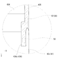
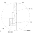
- engaging convex portions 433 that project toward a side wall 52 (see FIGS. 1 and 2) of the cover 50 described later and engage with the cover 50.
- two engaging projections 433 are provided on the side surface of the terminal block 434 in a central portion in the front-rear direction.
- the engaging convex portion 433 protrudes from the side surface of the terminal block 434 and is formed in a wedge shape so that the thickness increases downward.
- the maximum protruding height of the engaging convex portion 433 is the side wall 52 of the cover 50. Is less than the thickness.
- a step surface 435 is formed on the side surface of the side wall portion 43 s, and the side surface of the terminal block 434 is located on the inner side in the left-right direction with respect to the lower surface of the step surface 435. Details of the engagement structure between the case 40 (lower case 41) and the cover 50 will be described later.
- the upper case 44 is a member that covers the accommodation space 410 of the lower case 41 from above, and includes a top plate portion 45 disposed on the upper surface side of the circuit board 10 and a peripheral edge of the top plate portion 45. And a peripheral wall 46 erected downward.
- the top plate portion 45 and the peripheral wall 46 are integrally formed.
- An upper recess 460 that forms an opening 48 is formed in the front wall 46 f on the front side of the peripheral wall 46.
- the upper case 44 is formed of a resin such as polypropylene (PP) or polyamide (PA).
- the peripheral wall 46 is a portion that is inserted into the insertion groove 431 formed in the lower case 41 and engages with the lower case 41.
- the peripheral wall 46 is provided with an engagement hole 462 that engages with the engagement protrusion 432 provided in the insertion groove 431 of the lower case 41.
- the cover 50 is a member that is assembled to the case 40 (lower case 41) from above so as to cover the power terminal 80.
- the cover 50 includes an upper wall 51 in which a cover portion 510 that covers the power supply terminal 80 is formed on both the left and right sides, and a pair of left and right side walls 52 that are erected downward from both side edges of the upper wall 51.
- the left and right side walls 52 are portions that engage with the lower case 41 of the case 40, and more specifically on the side surfaces of the left and right side wall portions 43s, more specifically on the side surfaces of the terminal block 434 so as to sandwich the case 40 from the left and right sides. Arranged to overlap the outside.
- the lower end edge of the side wall 52 abuts on a step surface 435 formed on the side wall portion 43s, and the outer surface of the side wall 52 is substantially flush with the side surface of the side wall portion 43s.
- the upper wall 51 is disposed on the upper side of the case 40 (upper case 44), and the front side of the cover 510 is opened to insert the electric wire 100 (see FIG. 1).
- the cover 50 is made of a resin such as polypropylene (PP) or polyamide (PA).
- Each side wall 52 is provided with an engagement concave portion 53 to which an engagement convex portion 433 provided on the side surface of the side wall portion 43s (terminal block 434) of the lower case 41 is engaged.
- two engagement recesses 53 are provided side by side at the center in the front-rear direction (longitudinal direction), and the engagement recesses 53 are through holes. Since the maximum protrusion height of the engaging convex portion 433 is smaller than the thickness of the side wall 52 of the cover 50 as described above, the engaging convex portion 433 is accommodated in the engaging concave portion 53 and does not protrude from the outer surface of the side wall 52. . As shown in FIGS.
- slits 54 are formed on both sides of each engagement recess 53 in the front-rear direction so as to be cut upward from the lower end of the side wall 52.
- a lock piece 55 is provided between the slits 54. Since the lock piece portion 55 is cantilevered by the slits 54, it is easily elastically deformed in the left-right direction.
- the slit 54 is cut out from the lower end of the side wall 52 to the height position of the engaging recess 53.
- the cover 50 is assembled to the case 40 by fitting the side wall 52 of the cover 50 into the side surface of the case 40 (lower case 41) from above, and the side wall portion 43s (terminal block 434).
- the engaging convex part 433 on the side surface and the engaging concave part 53 on the side wall 52 are engaged.
- the case 40 and the cover 50 are engaged with each other by the engagement between the engagement convex portion 433 and the engagement concave portion 53 (see FIG. 1).
- an engagement recess 53 is provided in the lock piece 55 (see FIGS. 3 and 4) of the side wall 52. Therefore, when the cover 50 is assembled to the case 40 from above, the lock piece portion 55 is elastically deformed and rides along the engaging convex portion 433, and the engaging convex portion 433 engages with the engaging concave portion 53. Returns to elasticity.
- a locking piece 56 is provided on the side wall 52 of the cover 50, and a locking portion 436 for locking the locking piece 56 is provided on the side wall portion 43s of the case 40 (lower case 41). Yes.
- the locking piece 56 is locked to the locking portion 436, whereby the side wall 52 of the cover 50 is separated from the side surface of the case 40 (outward in the left-right direction). To restrict the movement.
- the locking piece 56 and the locking part 436 will be described in detail.
- the locking piece 56 is provided at a position shifted in the front-rear direction (longitudinal direction) of the side wall 52 with respect to the engaging recess 53.
- a locking piece 56 is formed on a front end edge that is a free end on the opening side into which the electric wire 100 is inserted in the cover 50 (covering portion 510) among the longitudinal edges of the side wall 52.
- the locking piece 56 is bent inward from the front end edge of the side wall 52 and extends forward, and is a plane perpendicular to the vertical direction (XY perpendicular to the Z direction in FIG. 1).
- the cross-sectional shape cut along the plane is substantially L-shaped.
- the outer surface of the locking piece 56 is located on the inner side in the left-right direction with respect to the outer surface of the side wall 52 provided with the engaging recess 53.
- the locking piece 56 only needs to be formed on at least the lower end side of the side wall 52 so as to be locked to the locking portion 436.
- a locking groove 436 a into which the locking piece 56 is inserted is provided on the upper surface of the side wall 43 s of the case 40 (lower case 41) as the locking portion 436.
- the lateral movement of the side wall 52 (hereinafter sometimes referred to as “outward direction”) is restricted.
- the board unit 1 of Embodiment 1 has the following effects.
- the case 40 and the cover 50 are engaged with each other by the engagement between the engagement convex portion 433 provided on the side wall portion 43 s of the case 40 (lower case 41) and the engagement concave portion 53 provided on the side wall 52 of the cover 50. Engage in the assembled state. Furthermore, the outward movement of the side wall 52 is restricted by the locking of the locking piece 56 provided on the side wall 52 of the cover 50 and the locking portion 436 provided on the side wall 43 s of the case 40. Therefore, even when the cover 50 is pressed from above, the engagement state between the engagement convex portion 433 and the engagement concave portion 53 is released by the engagement between the engagement piece 56 and the engagement portion 436. Is restricted from moving in the specified direction. Therefore, the engagement state between the engagement convex portion 433 and the engagement concave portion 53 can be stably maintained, and the cover 50 can be prevented from falling off from the case 40.
- the engaging recess 53 provided in the cover 50 is a through hole
- the engaging convex portion 433 provided in the case 40 becomes an engaging recess (through hole).
- the slit 54 is formed in the side wall 52 and the engagement concave portion 53 is provided in the lock piece portion 55, the lock piece portion 55 is elastically deformed and the engagement convex portion 433 is easily formed in the engagement concave portion 53. Can be engaged.
- the locking portion 436 provided in the case 40 is the locking groove 436a, and the locking piece 56 provided in the cover 50 is inserted into the locking groove 436a, so that the side wall 52 of the cover 50 is outward.
- the movement to the can be easily regulated.
- a locking projection 436 b is provided as a locking portion 436 that protrudes upward from the upper surface of the side wall 43 s of the lower case 41.
- the locking piece 56 extends forward from the front end edge of the side wall 52, is bent inward so as to sandwich the locking projection 436b, and has a substantially J-shaped cross section cut along a plane perpendicular to the vertical direction. . In this case, the outward movement of the side wall 52 of the cover 50 is restricted by the locking piece 56 being hooked on the locking projection 436b.
- an engagement convex portion protruding from the inner surface toward the side surface of the side wall portion 43 s of the case 40 is provided on the side wall 52 of the cover 50, and the engagement convex portion is engaged with the side surface of the side wall portion 43 s of the case 40. It is mentioned to provide an engaging recess. Even in this case, the case 40 and the cover 50 can be engaged by the engagement between the engagement convex portion and the engagement concave portion.
- the locking piece 56 is provided at a position shifted in the front-rear direction (longitudinal direction) of the side wall 52 with respect to the engaging convex portion provided on the side wall 52 of the cover 50.
- the substrate unit 1 is used for switching the power supply from the main battery and the auxiliary battery to the electrical component, but is not limited to this.
- it may be a board unit for other purposes arranged in a route from the power source of the vehicle to the load.
- the board unit according to the embodiment of the present invention can be suitably used for a high-current power control unit such as a DC voltage converter, an AC / DC converter, a DC / AC inverter, etc. mounted on a vehicle such as an automobile.
- a high-current power control unit such as a DC voltage converter, an AC / DC converter, a DC / AC inverter, etc. mounted on a vehicle such as an automobile.
Abstract
La présente invention concerne une unité de carte comprenant : une carte de circuit imprimé ; un boîtier qui contient la carte de circuit imprimé et qui présente une partie paroi périphérique ; une barre omnibus connectée électriquement à la carte de circuit imprimé et qui présente une partie sortie qui sort du boîtier ; une borne d'alimentation électrique qui connecte la partie sortie de la barre omnibus et une borne de connexion d'un fil électrique ; et un couvercle qui est monté par le haut par rapport au boîtier de manière à recouvrir la borne d'alimentation électrique, le couvercle présentant une paroi latérale qui chevauche la face extérieure d'une surface latérale de la partie paroi périphérique. Soit la surface latérale de la partie paroi périphérique du boîtier, soit la surface latérale de la paroi latérale du couvercle est pourvue d'une saillie de mise en prise qui fait saillie vers l'autre, et l'autre surface desdites surfaces est pourvue d'un évidement de mise en prise qui est saisi par la saillie de mise en prise. La paroi latérale du couvercle est pourvue d'une pièce de fixation disposée dans une position qui est décalée par rapport à la saillie de mise en prise ou à l'évidement de mise en prise dans le sens de la longueur. La partie paroi périphérique du boîtier est pourvue d'une partie fixation sur laquelle la pièce de fixation est fixée. En fixant la pièce de fixation sur la partie fixation, le mouvement de la paroi latérale du couvercle est limité dans une direction se séparant de la surface latérale de la partie paroi périphérique du boîtier.
Priority Applications (3)
| Application Number | Priority Date | Filing Date | Title |
|---|---|---|---|
| US16/306,070 US10561031B2 (en) | 2016-06-02 | 2017-05-31 | Board unit |
| CN201780033016.4A CN109219991B (zh) | 2016-06-02 | 2017-05-31 | 基板单元 |
| DE112017002767.5T DE112017002767T5 (de) | 2016-06-02 | 2017-05-31 | Platineneinheit |
Applications Claiming Priority (2)
| Application Number | Priority Date | Filing Date | Title |
|---|---|---|---|
| JP2016-111349 | 2016-06-02 | ||
| JP2016111349A JP6575930B2 (ja) | 2016-06-02 | 2016-06-02 | 基板ユニット |
Publications (1)
| Publication Number | Publication Date |
|---|---|
| WO2017209204A1 true WO2017209204A1 (fr) | 2017-12-07 |
Family
ID=60478732
Family Applications (1)
| Application Number | Title | Priority Date | Filing Date |
|---|---|---|---|
| PCT/JP2017/020335 WO2017209204A1 (fr) | 2016-06-02 | 2017-05-31 | Unité de carte |
Country Status (5)
| Country | Link |
|---|---|
| US (1) | US10561031B2 (fr) |
| JP (1) | JP6575930B2 (fr) |
| CN (1) | CN109219991B (fr) |
| DE (1) | DE112017002767T5 (fr) |
| WO (1) | WO2017209204A1 (fr) |
Families Citing this family (3)
| Publication number | Priority date | Publication date | Assignee | Title |
|---|---|---|---|---|
| DE102017204600A1 (de) * | 2017-03-20 | 2018-09-20 | Robert Bosch Gmbh | Verbinder zum Verbinden von zwei Gehäuseteilen und Gehäuse umfassend zwei Gehäuseteile und mindestens einen Verbinder |
| US11558972B2 (en) * | 2020-11-19 | 2023-01-17 | Aptiv Technologies Limited | Electrical center cover with machine-readable indicator confirmation of lock engagement |
| TWI794048B (zh) * | 2022-03-14 | 2023-02-21 | 英業達股份有限公司 | 快拆固定器 |
Citations (5)
| Publication number | Priority date | Publication date | Assignee | Title |
|---|---|---|---|---|
| JPH1051931A (ja) * | 1996-07-29 | 1998-02-20 | Yazaki Corp | 電気接続箱のカバーロック構造 |
| JPH1141748A (ja) * | 1997-07-17 | 1999-02-12 | Sumitomo Wiring Syst Ltd | 電気接続箱 |
| JP2001258120A (ja) * | 2000-03-14 | 2001-09-21 | Yazaki Corp | 電気接続箱へのブラケット取付構造 |
| JP2005065420A (ja) * | 2003-08-13 | 2005-03-10 | Yazaki Corp | 電気接続箱の防水構造 |
| JP2016067090A (ja) * | 2014-09-24 | 2016-04-28 | 住友電装株式会社 | 電気接続箱 |
Family Cites Families (40)
| Publication number | Priority date | Publication date | Assignee | Title |
|---|---|---|---|---|
| JPH0615457Y2 (ja) * | 1988-07-15 | 1994-04-20 | 矢崎総業株式会社 | 電気接続箱 |
| US5023752A (en) * | 1989-10-31 | 1991-06-11 | General Motors Corporation | Electrical power distribution center |
| US5795193A (en) * | 1996-10-23 | 1998-08-18 | Yazaki Corporation | Power distribution box with busbar having bolt retaining means |
| US5788529A (en) * | 1997-06-09 | 1998-08-04 | General Motors Corporation | Top down electrical distribution center assembly |
| US6350949B1 (en) * | 2000-06-23 | 2002-02-26 | Tyco Electronics Corp | Sealed power distribution module |
| JP2002330526A (ja) * | 2001-04-27 | 2002-11-15 | Yazaki Corp | 電気接続箱 |
| JP2003009347A (ja) * | 2001-06-20 | 2003-01-10 | Sumitomo Wiring Syst Ltd | 電気接続箱 |
| US6570088B1 (en) * | 2002-03-13 | 2003-05-27 | Sumitomo Wiring Systems, Ltd. | Junction box assembly |
| US6679708B1 (en) * | 2002-09-10 | 2004-01-20 | Sumitomo Wiring Systems, Ltd. | Vehicle junction box having power distribution center with terminal for jump-starting vehicle |
| JP4161877B2 (ja) * | 2003-11-05 | 2008-10-08 | 住友電装株式会社 | 回路構成体、その製造方法及び配電ユニット |
| JP4254494B2 (ja) | 2003-11-11 | 2009-04-15 | 住友電装株式会社 | 回路構成体 |
| JP4148110B2 (ja) * | 2003-11-26 | 2008-09-10 | 住友電装株式会社 | 回路構成体 |
| JP2005185056A (ja) * | 2003-12-22 | 2005-07-07 | T An T:Kk | 車両室内灯用バスバー基板 |
| JP4387314B2 (ja) * | 2005-01-07 | 2009-12-16 | 株式会社オートネットワーク技術研究所 | 電気接続箱 |
| JP4577061B2 (ja) | 2005-03-28 | 2010-11-10 | 住友電装株式会社 | 電気接続箱 |
| JP4832263B2 (ja) * | 2006-11-16 | 2011-12-07 | 株式会社オートネットワーク技術研究所 | 電気接続箱 |
| US7616438B2 (en) * | 2006-11-21 | 2009-11-10 | Autonetworks Technologies, Ltd. | Electric connection box |
| JP5005462B2 (ja) * | 2007-08-01 | 2012-08-22 | 株式会社オートネットワーク技術研究所 | 電気接続箱 |
| DE112009004602T5 (de) * | 2009-03-27 | 2012-07-05 | Mitsubishi Electric Corp. | Struktur zum Befestigen von metallischen Plattenabschnitten aneinander |
| JP5299698B2 (ja) * | 2009-10-28 | 2013-09-25 | 住友電装株式会社 | 電気接続箱 |
| JP5380376B2 (ja) * | 2010-06-21 | 2014-01-08 | 日立オートモティブシステムズ株式会社 | パワー半導体装置 |
| US8723031B2 (en) * | 2010-08-30 | 2014-05-13 | Hosiden Corporation | Terminal box |
| US20120268864A1 (en) * | 2011-04-21 | 2012-10-25 | Delphi Technologies, Inc. | Apparatus having plurality of openings to access removable electronic devices some of which have electrical connections using no circuit board trace |
| US9440601B2 (en) * | 2013-09-06 | 2016-09-13 | Johnson Controls Technology Company | System for providing voltage measurements of battery cells to a PCB within a battery module |
| JP6166654B2 (ja) * | 2013-12-26 | 2017-07-19 | 矢崎総業株式会社 | 電子回路ユニットにおける外装ケースの成形方法 |
| DE112015000733B4 (de) * | 2014-05-09 | 2018-07-19 | Autonetworks Technologies, Ltd. | Schaltungsbaugruppe, Struktur aus verbundenen Sammelschienen und elektrischer Verteiler |
| JP6187380B2 (ja) * | 2014-05-09 | 2017-08-30 | 株式会社オートネットワーク技術研究所 | 回路構成体および電気接続箱 |
| JP6310791B2 (ja) * | 2014-06-25 | 2018-04-11 | 矢崎総業株式会社 | スイッチボックス |
| JP5995113B2 (ja) * | 2014-07-02 | 2016-09-21 | 株式会社オートネットワーク技術研究所 | 電気接続箱 |
| JP6168362B2 (ja) * | 2014-09-05 | 2017-07-26 | 株式会社オートネットワーク技術研究所 | 回路構成体、電気接続箱及びスペーサ |
| JP6343249B2 (ja) * | 2014-10-15 | 2018-06-13 | 株式会社ミツバ | コントローラおよびコントローラの製造方法 |
| JP6413637B2 (ja) * | 2014-10-30 | 2018-10-31 | 株式会社オートネットワーク技術研究所 | 蓄電ユニット |
| KR20160066826A (ko) | 2014-12-03 | 2016-06-13 | 삼성전기주식회사 | 공통모드필터 및 그 제조방법 |
| JP6278243B2 (ja) * | 2015-01-07 | 2018-02-14 | 株式会社オートネットワーク技術研究所 | 蓄電ユニット |
| JP6653121B2 (ja) * | 2015-03-18 | 2020-02-26 | 住友電装株式会社 | 電気接続箱 |
| JP6488198B2 (ja) * | 2015-05-29 | 2019-03-20 | 株式会社ミツバ | 制御装置 |
| US9937798B2 (en) * | 2015-09-14 | 2018-04-10 | Sumitomo Wiring Systems, Ltd. | Wrap around bus bar for vehicle power distribution device |
| JP6378714B2 (ja) * | 2016-04-20 | 2018-08-22 | 矢崎総業株式会社 | 電気接続箱 |
| JP6434471B2 (ja) * | 2016-10-17 | 2018-12-05 | 矢崎総業株式会社 | 電子部品ユニット、電気接続箱、及び、ワイヤハーネス |
| JP6660914B2 (ja) * | 2017-04-27 | 2020-03-11 | 矢崎総業株式会社 | 電気接続箱およびワイヤハーネス |
-
2016
- 2016-06-02 JP JP2016111349A patent/JP6575930B2/ja active Active
-
2017
- 2017-05-31 CN CN201780033016.4A patent/CN109219991B/zh active Active
- 2017-05-31 WO PCT/JP2017/020335 patent/WO2017209204A1/fr active Application Filing
- 2017-05-31 US US16/306,070 patent/US10561031B2/en active Active
- 2017-05-31 DE DE112017002767.5T patent/DE112017002767T5/de active Pending
Patent Citations (5)
| Publication number | Priority date | Publication date | Assignee | Title |
|---|---|---|---|---|
| JPH1051931A (ja) * | 1996-07-29 | 1998-02-20 | Yazaki Corp | 電気接続箱のカバーロック構造 |
| JPH1141748A (ja) * | 1997-07-17 | 1999-02-12 | Sumitomo Wiring Syst Ltd | 電気接続箱 |
| JP2001258120A (ja) * | 2000-03-14 | 2001-09-21 | Yazaki Corp | 電気接続箱へのブラケット取付構造 |
| JP2005065420A (ja) * | 2003-08-13 | 2005-03-10 | Yazaki Corp | 電気接続箱の防水構造 |
| JP2016067090A (ja) * | 2014-09-24 | 2016-04-28 | 住友電装株式会社 | 電気接続箱 |
Also Published As
| Publication number | Publication date |
|---|---|
| US20190141844A1 (en) | 2019-05-09 |
| JP6575930B2 (ja) | 2019-09-18 |
| US10561031B2 (en) | 2020-02-11 |
| CN109219991B (zh) | 2020-09-18 |
| JP2017220471A (ja) | 2017-12-14 |
| CN109219991A (zh) | 2019-01-15 |
| DE112017002767T5 (de) | 2019-02-14 |
Similar Documents
| Publication | Publication Date | Title |
|---|---|---|
| WO2015194666A1 (fr) | Boîte de jonction électrique et boîtier de connecteur | |
| US10820432B2 (en) | Board unit with a tool-insertion recessed portion to release engagement between the case and the cover | |
| WO2017209204A1 (fr) | Unité de carte | |
| JPWO2006109597A1 (ja) | 電気接続箱 | |
| JP2011097711A (ja) | 電気接続箱 | |
| JP2005117741A (ja) | 電気接続箱 | |
| KR101653062B1 (ko) | 전기 커넥터 | |
| JP2006109587A (ja) | 電線と素子内蔵ユニットとの接続構造 | |
| JP2009017757A (ja) | 電気接続箱 | |
| JP2004328939A (ja) | 電気接続箱 | |
| WO2014010374A1 (fr) | Structure de fixation pour porte-fusible et couvercle de fusible | |
| JPWO2006115101A1 (ja) | 電気接続箱 | |
| JP2007282401A (ja) | 電気接続箱 | |
| US20210287843A1 (en) | Coil assembly, circuit assembly, and electrical junction box | |
| US20230361548A1 (en) | Electrical junction box | |
| JP2015084613A (ja) | 電気接続箱 | |
| JP2013065695A (ja) | 電動機制御装置 | |
| JP5590409B2 (ja) | 電気接続箱 | |
| JP5545491B2 (ja) | 回路構成体 | |
| JP2011097805A (ja) | 電気接続箱 | |
| JP5888801B1 (ja) | 電気接続箱 | |
| JP2006180686A (ja) | 電気接続箱 | |
| JP4856517B2 (ja) | 電力分配装置 | |
| JP2014217254A (ja) | 電気接続箱及び電気接続箱組立体 | |
| JP2006191732A (ja) | 回路構成体及びこれを用いた電気接続箱 |
Legal Events
| Date | Code | Title | Description |
|---|---|---|---|
| 121 | Ep: the epo has been informed by wipo that ep was designated in this application |
Ref document number: 17806755 Country of ref document: EP Kind code of ref document: A1 |
|
| 122 | Ep: pct application non-entry in european phase |
Ref document number: 17806755 Country of ref document: EP Kind code of ref document: A1 |