WO2017047715A1 - 眼内レンズ挿入器具 - Google Patents
眼内レンズ挿入器具 Download PDFInfo
- Publication number
- WO2017047715A1 WO2017047715A1 PCT/JP2016/077328 JP2016077328W WO2017047715A1 WO 2017047715 A1 WO2017047715 A1 WO 2017047715A1 JP 2016077328 W JP2016077328 W JP 2016077328W WO 2017047715 A1 WO2017047715 A1 WO 2017047715A1
- Authority
- WO
- WIPO (PCT)
- Prior art keywords
- intraocular lens
- insertion device
- lens
- optical
- holding
- Prior art date
Links
Images

Classifications
-
- A—HUMAN NECESSITIES
- A61—MEDICAL OR VETERINARY SCIENCE; HYGIENE
- A61F—FILTERS IMPLANTABLE INTO BLOOD VESSELS; PROSTHESES; DEVICES PROVIDING PATENCY TO, OR PREVENTING COLLAPSING OF, TUBULAR STRUCTURES OF THE BODY, e.g. STENTS; ORTHOPAEDIC, NURSING OR CONTRACEPTIVE DEVICES; FOMENTATION; TREATMENT OR PROTECTION OF EYES OR EARS; BANDAGES, DRESSINGS OR ABSORBENT PADS; FIRST-AID KITS
- A61F2/00—Filters implantable into blood vessels; Prostheses, i.e. artificial substitutes or replacements for parts of the body; Appliances for connecting them with the body; Devices providing patency to, or preventing collapsing of, tubular structures of the body, e.g. stents
- A61F2/02—Prostheses implantable into the body
- A61F2/14—Eye parts, e.g. lenses, corneal implants; Implanting instruments specially adapted therefor; Artificial eyes
- A61F2/16—Intraocular lenses
- A61F2/1662—Instruments for inserting intraocular lenses into the eye
- A61F2/1667—Instruments for inserting intraocular lenses into the eye with rotatable plungers
-
- A—HUMAN NECESSITIES
- A61—MEDICAL OR VETERINARY SCIENCE; HYGIENE
- A61F—FILTERS IMPLANTABLE INTO BLOOD VESSELS; PROSTHESES; DEVICES PROVIDING PATENCY TO, OR PREVENTING COLLAPSING OF, TUBULAR STRUCTURES OF THE BODY, e.g. STENTS; ORTHOPAEDIC, NURSING OR CONTRACEPTIVE DEVICES; FOMENTATION; TREATMENT OR PROTECTION OF EYES OR EARS; BANDAGES, DRESSINGS OR ABSORBENT PADS; FIRST-AID KITS
- A61F2/00—Filters implantable into blood vessels; Prostheses, i.e. artificial substitutes or replacements for parts of the body; Appliances for connecting them with the body; Devices providing patency to, or preventing collapsing of, tubular structures of the body, e.g. stents
- A61F2/02—Prostheses implantable into the body
- A61F2/14—Eye parts, e.g. lenses, corneal implants; Implanting instruments specially adapted therefor; Artificial eyes
- A61F2/16—Intraocular lenses
- A61F2/1662—Instruments for inserting intraocular lenses into the eye
- A61F2/167—Instruments for inserting intraocular lenses into the eye with pushable plungers
-
- A—HUMAN NECESSITIES
- A61—MEDICAL OR VETERINARY SCIENCE; HYGIENE
- A61F—FILTERS IMPLANTABLE INTO BLOOD VESSELS; PROSTHESES; DEVICES PROVIDING PATENCY TO, OR PREVENTING COLLAPSING OF, TUBULAR STRUCTURES OF THE BODY, e.g. STENTS; ORTHOPAEDIC, NURSING OR CONTRACEPTIVE DEVICES; FOMENTATION; TREATMENT OR PROTECTION OF EYES OR EARS; BANDAGES, DRESSINGS OR ABSORBENT PADS; FIRST-AID KITS
- A61F2/00—Filters implantable into blood vessels; Prostheses, i.e. artificial substitutes or replacements for parts of the body; Appliances for connecting them with the body; Devices providing patency to, or preventing collapsing of, tubular structures of the body, e.g. stents
- A61F2/02—Prostheses implantable into the body
- A61F2/14—Eye parts, e.g. lenses, corneal implants; Implanting instruments specially adapted therefor; Artificial eyes
- A61F2/16—Intraocular lenses
-
- A—HUMAN NECESSITIES
- A61—MEDICAL OR VETERINARY SCIENCE; HYGIENE
- A61F—FILTERS IMPLANTABLE INTO BLOOD VESSELS; PROSTHESES; DEVICES PROVIDING PATENCY TO, OR PREVENTING COLLAPSING OF, TUBULAR STRUCTURES OF THE BODY, e.g. STENTS; ORTHOPAEDIC, NURSING OR CONTRACEPTIVE DEVICES; FOMENTATION; TREATMENT OR PROTECTION OF EYES OR EARS; BANDAGES, DRESSINGS OR ABSORBENT PADS; FIRST-AID KITS
- A61F9/00—Methods or devices for treatment of the eyes; Devices for putting-in contact lenses; Devices to correct squinting; Apparatus to guide the blind; Protective devices for the eyes, carried on the body or in the hand
- A61F9/007—Methods or devices for eye surgery
- A61F9/00736—Instruments for removal of intra-ocular material or intra-ocular injection, e.g. cataract instruments
-
- A—HUMAN NECESSITIES
- A61—MEDICAL OR VETERINARY SCIENCE; HYGIENE
- A61F—FILTERS IMPLANTABLE INTO BLOOD VESSELS; PROSTHESES; DEVICES PROVIDING PATENCY TO, OR PREVENTING COLLAPSING OF, TUBULAR STRUCTURES OF THE BODY, e.g. STENTS; ORTHOPAEDIC, NURSING OR CONTRACEPTIVE DEVICES; FOMENTATION; TREATMENT OR PROTECTION OF EYES OR EARS; BANDAGES, DRESSINGS OR ABSORBENT PADS; FIRST-AID KITS
- A61F2/00—Filters implantable into blood vessels; Prostheses, i.e. artificial substitutes or replacements for parts of the body; Appliances for connecting them with the body; Devices providing patency to, or preventing collapsing of, tubular structures of the body, e.g. stents
- A61F2/02—Prostheses implantable into the body
- A61F2/14—Eye parts, e.g. lenses, corneal implants; Implanting instruments specially adapted therefor; Artificial eyes
- A61F2/16—Intraocular lenses
- A61F2002/1681—Intraocular lenses having supporting structure for lens, e.g. haptics
- A61F2002/1683—Intraocular lenses having supporting structure for lens, e.g. haptics having filiform haptics
Definitions
- the present invention relates to an intraocular lens insertion device used when an intraocular lens is inserted into the eye.
- the cataract operations it is widely practiced to remove a white cloudy lens by ultrasonic emulsification and then insert an intraocular lens into the eye.
- a one-piece type intraocular lens made of a soft material such as silicone elastomer or soft acrylic is inserted into the eye in a small folded state in order to realize a minimally invasive cataract surgery with less burden on the eye. Things have been done.
- the one-piece type intraocular lens has an optical part that performs a lens function and a pair of support parts extending from the optical part, and the entire intraocular lens is made of a soft material.
- an intraocular lens in order to improve the operability of inserting an intraocular lens by the operator as much as possible, an intraocular lens is provided so as to hold a pair of support parts with an optical part.
- Some have a function of folding see, for example, Patent Document 1).
- Some conventional intraocular lens insertion devices include an extrusion member that pushes out an intraocular lens, and the intraocular lens is folded when the intraocular lens is pushed out by the extrusion member.
- the main object of the present invention is to provide an intraocular lens insertion device capable of reliably placing the tip of the support part on the surface of the optical part when the intraocular lens is folded so that the support part is held by the optical part. It is to provide.
- the first aspect of the present invention is: An intraocular lens insertion device for inserting an intraocular lens having an optical part and a pair of support parts extending from the optical part into the eye, An insertion instrument body provided with a lens installation part in which the intraocular lens is installed; A holding part for holding a front end part of a front support part disposed in front of the lens installation part among the pair of support parts; A displacement mechanism for displacing the optical part relatively downward with respect to the front support part held by the holding part; It is provided with the intraocular lens insertion instrument characterized by the above-mentioned.
- the second aspect of the present invention is: An extrusion member that pushes out the intraocular lens from the lens installation portion by moving in the central axis direction of the insertion instrument body;
- the displacement mechanism includes a guide mechanism that guides the optical unit so as to pass under the holding unit when the intraocular lens is pushed out by the pushing member.
- This is an intraocular lens insertion device.
- the third aspect of the present invention is:
- the holding part has an accommodating part that detachably accommodates the tip part of the front support part,
- the second feature of the present invention is characterized in that when the optical part is pushed by the push member and passes under the holding part, the front end part of the front support part is detached from the accommodating part.
- the fourth aspect of the present invention is: The guide mechanism is inclined in the same direction as the first guide portion at a position facing the first guide portion and a first guide portion formed on the lower surface of the holding portion in a state inclined with respect to a horizontal plane.
- the intraocular lens insertion device according to the second aspect characterized in that the intraocular lens insertion device according to the second aspect.
- the push member has a rod portion that pushes out the intraocular lens while being displaced downward along the inclination of the second guide portion.
- the intraocular lens insertion device according to the fourth aspect .
- the sixth aspect of the present invention is: The intraocular lens insertion device according to any one of the first to fifth aspects, wherein the intraocular lens is preinstalled in the lens installation unit.
- the seventh aspect of the present invention is The intraocular lens insertion device according to any one of the first to sixth aspects, wherein the intraocular lens is installed in a no-load state in the lens installation unit.
- the distal end portion of the support portion when the intraocular lens is folded so that the support portion is held by the optical portion, the distal end portion of the support portion can be reliably placed on the surface of the optical portion.
- FIG. 1 is a perspective view showing an overall configuration of an intraocular lens insertion device according to an embodiment of the present invention. It is a sectional side view which shows the whole structure of the intraocular lens insertion instrument which concerns on embodiment of this invention.
- (A) is a plane sectional view which shows the principal part structure of the intraocular lens insertion instrument which concerns on embodiment of this invention,
- (B) is a sectional side view which shows the said principal part structure.
- A) is a perspective view explaining the shape of the protrusion guide formed in the advancing direction of a rod part
- (B) is a figure which shows the cross-sectional shape in the top part of a protrusion guide
- C) is a protrusion guide.
- FIG. 1 It is a figure which shows the cross-sectional shape of the rod part which passes.
- FIG. 1 A)-(D) are figures which show the mode of movement of an extrusion member accompanying rotation operation of an operation part in time series.
- FIG. 1 A)-(D) is a figure which shows a mode that the front-end
- FIG.) is a perspective view which shows the cross-sectional shape in the top part of a protrusion guide,
- B) is the same front view.
- (A) is a perspective view which shows the cross-sectional shape in the top part of a protrusion guide, (B) is the same front view.
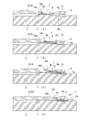
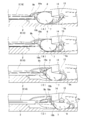
- FIG. 1 A) to (D) are plan sectional views showing the movement of the intraocular lens pushed out by the pushing member in time series.
- FIG. 1 A) to (D) are side cross-sectional views showing the movement of the intraocular lens pushed out by the pushing member in time series.
- FIG. 1 A)-(D) are perspective views showing the movement of the intraocular lens pushed out by the pushing member in time series.
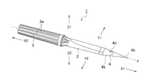
- FIG. 1 is a perspective view showing the overall configuration of an intraocular lens insertion device according to an embodiment of the present invention
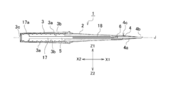
- FIG. 2 is a side sectional view showing the overall configuration of the intraocular lens insertion device according to an embodiment of the present invention.
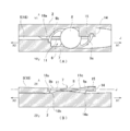
- FIG. 3A is a cross-sectional plan view showing the main configuration of the intraocular lens insertion device according to the embodiment of the present invention
- FIG. 3B is a side cross-sectional view showing the main configuration.
- the illustrated intraocular lens insertion device 1 is provided as a disposable product, and is used when an intraocular lens is inserted into the eye.
- the intraocular lens insertion device 1 includes an insertion device body 2, an operation unit 3, an insertion tube 4, and a push member 5. Each part of the intraocular lens insertion device 1 is made of resin.
- the intraocular lens insertion device 1 is a preload type in which an intraocular lens is previously installed. In the preload-type intraocular lens insertion device 1, the intraocular lens is installed in advance in a lens installation unit (to be described later) when the intraocular lens insertion device 1 is shipped from the factory.
- the X1 direction is the front end side (front), and the X2 direction is the rear end side (rear).
- the Y1 direction is the left side (left side)
- the Y2 direction is the right side (right side)
- the Z1 direction is the upper side (upper side)
- the Z2 direction is the lower side (lower side).
- the X1 direction and the X2 direction correspond to the central axis direction of the intraocular lens insertion device 1 (hereinafter, also simply referred to as “central axis direction”)
- the Y1 direction and the Y2 direction are the intraocular lens insertion device 1.
- the Z1 direction and the Z2 direction correspond to the height direction (vertical direction) of the intraocular lens insertion device 1.
- a horizontal plane parallel to the X1 direction, the X2 direction, the Y1 direction, and the Y2 direction is used, and a plane perpendicular to the horizontal plane is a vertical plane.
- the symbol J in the figure indicates the central axis of the intraocular lens insertion device 1.
- the insertion instrument body 2 is formed in a cylindrical shape as a whole.
- a hollow portion that allows movement of the pusher member 5 in the X1 direction and the X2 direction is formed inside the insertion instrument body 2.
- a lens installation portion 6 is provided at the distal end portion of the insertion instrument body 2.
- the lens installation portion 6 is formed so as to protrude forward from the lower outer peripheral wall of the insertion instrument body 2.
- the intraocular lens 7 is installed in the lens installation unit 6.
- a central axis J of the intraocular lens insertion instrument 1 is coincident with each central axis of the insertion instrument body 2, the operation unit 3, and the insertion cylinder 4.
- a one-piece type intraocular lens 7 made of a soft material such as silicone elastomer or soft acrylic is handled.
- the intraocular lens 7 includes an optical unit 8 that performs an optical function, and a pair (two) of support units 9a and 9b that extend outwardly from the outer peripheral edge of the optical unit 8 in an arc shape. Yes.
- the optical unit 8 is formed in a circular shape in plan view.
- the pair of support portions 9a and 9b are each formed in an elongated arm shape. In FIG. 2, the notation of the intraocular lens 7 is omitted.
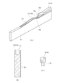
- FIG. 4B is a cross-sectional view of the portion where the protruding guide 11 is formed as viewed from the central axis direction (front). As can be seen from this figure, a concave groove 12 is formed at a portion where the protruding guide 11 is formed.
- the protruding guide 11 has an inclined portion 11a with an inclination, an apex portion 11b that cannot be inclined, and a downward inclined portion 11c with a gentler inclination than the inclined portion 11a.
- the protruding guide 11 is initially an upward inclined portion 11a from the rear end side to the front end side of the intraocular lens insertion device 1, and after passing the top portion 11b.
- the slope 11c is a gentle downward slope.
- the groove 12 has the deepest depth at the top 11b of the protruding guide 11, and FIG. 4B shows a cross section of the top 11b. Note that reference numeral 2a in FIGS. 4A and 4B shows a part of the insertion instrument body 2 virtually cut out, and a part of the insertion instrument body 2 has a shape as shown in the figure. I don't mean. This also applies to FIGS. 6 to 8.
- the lens installation portion 6 is formed with a pair of concave grooves (not shown).
- the pair of concave grooves are formed on the left and right side walls defining the lens installation portion 6 of the insertion instrument body 2 so as to face each other.
- the pair of concave grooves regulate the vertical movement of the optical unit 8 by fitting a part of the outer peripheral edge of the optical unit 8 when the intraocular lens 7 is installed in the lens installation unit 6.
- the holding part 14 is formed in a state in which the left side wall part of the left and right side wall parts defining the lens installation part 6 is partially protruded.
- a part of the lower surface of the holding portion 14 is an inclined surface 14a (see FIG. 3B).
- the inclined surface 14 a of the holding part 14 is formed on the lower surface of the holding part 14 as an example of the “first guide part”.
- the downward inclined portion 11c of the protruding guide 11 described above is formed in the lens installation portion 6 as an example of a “second guide portion”.
- the first guide unit and the second guide unit described here pass the optical unit 8 so as to pass under the holding unit 14 when the intraocular lens 7 installed in the lens installation unit 6 is pushed out by the pushing member 5. It becomes an element constituting a guide mechanism for guiding.
- the inclined surface 14a is formed in an inclined state with respect to the horizontal plane. Specifically, the inclined surface 14a is inclined with respect to the horizontal plane so that the front of the inclined surface 14a is lower than the rear. Moreover, the inclined surface 14a is arrange
- the holding portion 14 is formed with a receiving portion 15.
- the accommodating part 15 accommodates the front-end
- the accommodating portion 15 is formed in a concave shape at the right end portion of the upper surface of the holding portion 14 so as to open upward and rightward.
- the opposing distance between the left and right side walls that define the lens installation portion 6 is gradually narrowed. This is because the optical portion 8 of the intraocular lens 7 is transferred to the insertion tube 4 in a state where the optical portion 8 is slightly rounded by the left and right side wall portions.
- the intraocular lens 7 has one support unit 9 a disposed in front of the lens installation unit 6 and the other support unit 9 b disposed in the rear of the lens installation unit 6. Installed at. Therefore, one support portion 9a corresponds to a “front support portion”, and the other support portion 9b corresponds to a “rear support portion”. Further, in the lens installation unit 6, the optical unit 8 of the intraocular lens 7 is installed (placed) on the top 11 b of the protruding guide 11 in a substantially horizontal state.
- a part of the holding unit 14 and a part of the optical unit 8 are arranged in a planar manner. Is done. Specifically, a part of the outer peripheral portion of the optical unit 8 is disposed below the inclined surface 14 a of the holding unit 14.
- the distal end portion of the support unit 9 a is accommodated in the accommodation unit 15 of the holding unit 14, thereby moving the support unit 9 a relative to the central axis direction, The rearward movement of the support portion 9a is restricted.
- the operation unit 3 is coaxially connected to the rear end portion of the insertion instrument body 2. In this connected state, the operation unit 3 is supported so as to be rotatable around the central axis of the insertion instrument body 2.
- the operation unit 3 is formed in a cylindrical shape.
- a plurality of ridges 3 a are formed on the outer peripheral surface of the operation unit 3.
- Each protrusion 3 a is formed in parallel with the longitudinal direction of the operation unit 3.
- the operation unit 3 is a portion that is rotated by a user such as an operator when the intraocular lens 7 is pushed out by the pushing member 5. At this time, if a plurality of protrusions 3a are formed on the outer peripheral part of the operation part 3, the user's finger is caught by the protrusions 3a, so that the operation part 3 can be easily rotated.
- a first screw part 3b is formed on the inner peripheral surface of the operation part 3.
- the first screw part 3b constitutes a female screw.
- the first screw portion 3b is formed over almost the entire central axis direction of the operation portion 3.
- An abutting portion 3 c is formed at the rear end portion of the operation portion 3.
- the abutting portion 3c is formed by bending inward so that the opening diameter of the rear end portion of the operation portion 3 is reduced.
- the abutting portion 3 c is a portion against which the rear end portion of the plunger portion 17 is abutted so that the plunger portion 17 does not protrude rearward from the rear end portion of the operation portion 3.
- the insertion tube 4 is for guiding the intraocular lens 7 into the eye in a state where the intraocular lens 7 is folded into a small size when the intraocular lens 7 installed in the lens installation unit 6 is inserted into the eye.
- the insertion tube 4 integrally includes a hollow insertion tube body 4a and a thin tubular nozzle portion 4b.
- the insertion tube 4 is attached to the distal end portion of the insertion instrument body 2. In this mounted state, the lens installation portion 6 of the insertion instrument main body 2 is accommodated and disposed in the insertion cylinder main body 4 a of the insertion cylinder 4.
- An injection part 4c is formed on the upper wall of the insertion cylinder body 4a.
- the injection part 4c is for injecting a viscoelastic substance (for example, sodium hyaluronate).
- a viscoelastic substance for example, sodium hyaluronate.
- the viscoelastic substance injected from the injection part 4 c is released in the vicinity of the intraocular lens 7 installed in the lens installation part 6, whereby the viscoelastic substance is supplied to the intraocular lens 7.
- the injection of the viscoelastic substance is performed before the intraocular lens 7 is pushed out by the pushing member 5.
- the diameter of the distal end side of the insertion cylinder body 4a is gradually reduced.
- the nozzle portion 4 b is formed at the distal end portion of the insertion cylinder 4.
- the tip of the nozzle part 4b is opened with an oblique cut. For this reason, the opening of the nozzle part 4b faces diagonally downward.
- the distal end portion of the nozzle portion 4b is a portion that is inserted into the incision of the eyeball when the intraocular lens 7 is inserted into the eye using the intraocular lens insertion device 1.
- the pushing member 5 is provided so as to be movable in the central axis direction of the insertion instrument body 2.
- the pushing member 5 pushes the intraocular lens 7 from the lens installation portion 6 by moving in the central axis direction of the insertion instrument body 2. At that time, the pushing member 5 moves in the hollow portion formed by the insertion instrument main body 2, the operation portion 3, and the insertion tube 4.
- the extrusion member 5 has a plunger portion 17 and a rod portion 18.
- the plunger part 17 and the rod part 18 may constitute the extrusion member 5 in an integral structure, or the plunger part 17 and the rod part 18 are made as separate structures, and these are assembled to each other to form the extrusion member. 5 may be included.
- the plunger portion 17 is disposed relatively rearward, and the rod portion 18 is disposed relatively forward.
- the plunger portion 17 is formed in a rod shape. In an initial state before use, the plunger portion 17 is arranged in a state of being inserted into the operation portion 3 so as not to protrude from the rear end portion of the operation portion 3. A second screw portion 17 a is formed at the rear end portion of the plunger portion 17. The second screw portion 17a forms a male screw. The second screw portion 17 a meshes with the first screw portion 3 b inside the operation portion 3.
- the operation unit 3 is operated so as to rotate around the central axis of the insertion instrument body 2, thereby moving the entire pushing member 5 forward.
- the movement start position of the plunger part 17 at that time is uniquely determined by abutting the rear end part of the plunger part 17 against the abutting part 3 c of the operation part 3.
- the rod part 18 folds the intraocular lens 7 into a predetermined shape by pushing the intraocular lens 7 installed in the lens installation part 6 forward, and in this state, the intraocular lens 7 is inserted into the nozzle part 4 b of the insertion tube 4. It is made to discharge from the opening part.
- the rod portion 18 is formed in a bar shape thinner than the plunger portion 17.
- the rod portion 18 is configured to be elastically deformable so as to have appropriate flexibility.
- a first contact portion 18 a and a second contact portion 18 b are formed at the distal end portion of the rod portion 18.
- the first contact portion 18a is in contact with the support portion 9b
- the second contact portion 18b is a portion in contact with the optical portion 8.
- the upper end portion of the second contact portion 18b protrudes in a bowl shape so that the edge of the optical portion 8 can be gripped.
- a protrusion 19 is formed on the lower surface of the rod portion 18 as shown in FIG.
- the protrusion 19 is formed on the rear end side of the rod portion 18 with respect to the length direction of the rod portion 18 so as to avoid the formation portion of the first contact portion 18a and the second contact portion 18b.
- the insertion instrument body 2 is attached to the operation unit 3.
- the rod portion 18 of the pushing member 5 is inserted into the hollow portion of the insertion instrument body 2.
- tip part (18a, 18b) of the rod part 18 is arrange
- the intraocular lens 7 prepared separately is installed in the lens installation part 6 of the insertion instrument body 2.
- the optical part 8 of the intraocular lens 7 is placed almost horizontally on the top 11 b of the protruding guide 11.
- One support portion 9 a is disposed in front of the lens installation portion 6, and the tip end portion of the support portion 9 a is accommodated in the accommodating portion 15 of the holding portion 14.
- the no-load state refers to a state in which almost no load (pressure) is applied to the intraocular lens, that is, a state in which the intraocular lens maintains its original shape.
- the original shape of the intraocular lens refers to a shape at the stage where the manufacture of the intraocular lens is finished.
- the insertion tube 4 is attached to the distal end portion of the insertion instrument body 2.
- the assembly of the intraocular lens insertion device 1 incorporating the intraocular lens 7 is completed.
- the description and drawings of Japanese Patent Application No. 2014-55761 Japanese Patent Laid-Open No. 2015-2015). No. 177845
- Japanese Patent Application No. 2014-55761 Japanese Patent Laid-Open No. 2015-2015. No. 177845
- other connection structures may be employed.
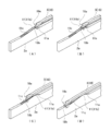
- FIG. 5A shows a stage in which the tip of the rod portion 18 of the push-out member 5 has been advanced to the tip of the lens installation portion 6, and FIG. 5B shows that the tip of the rod portion 18 is inserted into the insertion tube 4.
- the stage which advanced to the cylinder main body 4a is shown.
- 5C shows a stage in which the tip of the rod portion 18 is advanced to the nozzle portion 4b of the insertion cylinder 4, and
- FIG. 5D shows the stage of the rod portion 18 at the nozzle portion 4b of the insertion cylinder 4.
- the stage which protruded ahead rather than is shown.
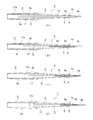
- the tip portion (the portion indicated by reference numerals 18a and 18b) of the rod portion 18 protrudes as shown in FIG. 6 (A).
- the guide 11 is displaced upward according to the upward inclined portion 11a.
- the tip of the rod portion 18 reaches the top 11b of the protruding guide 11 as shown in FIG.
- the tip of the rod portion 18 is displaced downward according to the downward inclined portion 11c of the protruding guide 11.
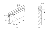
- the cross-sectional shape in the top part 11b of the protrusion guide 11 becomes like FIG. 7 (A), (B). That is, after the tip of the rod portion 18 passes through the top 11 b of the protruding guide 11, a part of the protrusion 19 formed on the lower surface of the rod portion 18 enters the groove 12 of the protruding guide 11. Thereby, the front-end
- the tip end of the rod portion 18 finishes descending the inclined portion 11c of the protruding guide 11 and proceeds forward.
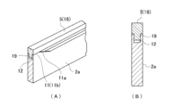
- the cross-sectional shape of the top portion 11b of the protruding guide 11 is as shown in FIGS. That is, after the tip of the rod portion 18 has passed through the inclined portion 11 c of the protruding guide 11, all of the protrusions 19 formed on the lower surface of the rod portion 18 enter the groove 12 of the protruding guide 11. Thereby, interference with the protrusion guide 11 and the rod part 18 can be avoided, and the front-end
- the tip portion of the rod portion 18 sequentially contacts the support portion 9b and the optical portion 8 (FIG. 9A, FIG. 10). (See (A) and FIG. 11 (A)). Specifically, the first contact portion 18a of the rod portion 18 first contacts the support portion 9b, and then the second contact portion 18b of the rod portion 18 contacts the optical portion 8. At this time, the first contact portion 18a of the rod portion 18 bends the entire support portion 9b in a substantially U shape toward the optical portion 8 side by pushing the support portion 9b forward while being in contact with the support portion 9b.
- the tip end of the support portion 9 b is placed on the first contact portion 18 a, and in this state, the tip end portion of the rod portion 18 is displaced upward along the upward inclined portion 11 a of the protruding guide 11.
- the tip of the rod portion 18 reaches the top 11 b of the protruding guide 11
- the second contact portion 18 b comes into contact with the edge of the optical portion 8.
- the tip of the support portion 9 b rides on the surface of the optical portion 8.
- the entire intraocular lens 7 is pushed forward while the tip of the rod portion 18 is in contact with the support portion 9b and the optical portion 8 (FIGS. 9B, 10B, and 11B). reference).
- the distal end portion of the rod portion 18 advances along the top portion 11b of the protruding guide 11 while gripping the edge of the optical portion 8 with the second contact portion 18b.
- the optical part 8 of the intraocular lens 7 is pushed out from the top 11b of the protruding guide 11 to the inclined part 11c.
- the optical part 8 thus pushed out is inclined obliquely along the downward inclined part 11 c of the protruding guide 11.
- the entire support portion 9 a is bent by the movement of the optical portion 8 while the tip portion of the support portion 9 a is accommodated in the accommodation portion 15 of the holding portion 14.
- the reason why the support portion 9a is bent in this way is as follows. First, the forward movement of the support portion 9a is restricted by being accommodated in the accommodating portion 15 of the holding portion 14. For this reason, even if the optical portion 8 is pushed forward by being pushed by the rod portion 18, the distal end portion of the support portion 9 a is caught there by being caught by the accommodating portion 15. Therefore, when the optical unit 8 is pushed forward at the tip of the rod part 18, a force in the direction opposite to the pushing direction is applied to the support part 9a. For this reason, the support part 9a is gradually bent as the optical part 8 moves.
- the entire intraocular lens 7 is pushed further forward while the tip of the rod portion 18 contacts both the support portion 9b and the optical portion 8 (FIGS. 9C, 10C, and 11C). )).
- the distal end portion of the rod portion 18 is displaced downward along the downward inclined portion 11c of the protruding guide 11 while gripping the edge of the optical portion 8 by the second contact portion 18b.
- the optical unit 8 is guided obliquely by the downward inclined portion 11c of the protruding guide 11 and the inclined surface 14a of the holding portion 14 facing the protruding portion 11 and moves obliquely downward.
- the support portion 9 a is bent more greatly by the movement of the optical portion 8 while the tip portion is held in the housing portion 15 of the holding portion 14. Specifically, the entire support portion 9a is bent toward the optical portion 8 so as to form a substantially U shape. At this time, the position of the optical part 8 is displaced downward relative to the position of the support part 9a by the above-described movement of the optical part 8 obliquely downward.
- the tip part of the support part 9a separates the accommodating part 15 of the holding part 14 (FIG. 9D, FIG. 10). D) and FIG. 11D).
- the distal end portion of the support portion 9 a detached from the housing portion 15 gets on the surface of the optical portion 8 that is passing under the holding portion 14.
- the optical unit 8 on which the distal end portion of the support portion 9a is placed is gradually deformed by being pushed by the left and right side wall portions of the lens installation portion 6, and the base end side portion of the support portion 9a is also one of the lens installation portions 6. In contact with the side wall. Thereby, the return of the shape of the support part 9a is suppressed. For this reason, the support portion 9a is maintained in a substantially U-shaped bent state without returning to its original shape, and the tip end portion of the support portion 9a is maintained on the surface of the optical portion 8. .
- the intraocular lens 7 is pushed into the insertion tube 4 by the movement of the rod portion 18.
- the optical part 8 of the intraocular lens 7 is rounded from the left and right by the inner wall of the insertion cylinder body 4a having a tapered shape, and finally folded so as to embrace the pair of support parts 9a and 9b. .
- the intraocular lens 7 folded in this way is pushed out from the nozzle portion 4 b of the insertion tube 4 by the rod portion 18.
- the intraocular lens 7 can be inserted into the eye by pushing the intraocular lens 7 through the opening of the nozzle part 4b with the nozzle part 4b of the insertion tube 4 inserted into the incision of the eyeball.
- the distal end portion of the support portion 9a of the intraocular lens 7 installed in the lens installation portion 6 of the insertion instrument body 2 is held by the holding portion 14, and the support portion 9a A displacement mechanism for displacing the optical unit 8 relatively downward is provided. For this reason, the front-end
- the optical portion 8 passes under the holding portion 14 by being pushed by the pushing member 5.
- the distal end portion of the support portion 9 a is configured to be detached from the accommodating portion 15. For this reason, using the pushing operation of the pushing member 5, the tip of the support portion 9 a can be detached from the housing portion 15 and placed on the surface of the optical portion 8 while bending the support portion 9 a to the optical portion 8 side. it can.
- the preload type intraocular lens insertion device 1 in which the intraocular lens 7 is preset in the lens installation unit 6 is employed. For this reason, the user who uses the intraocular lens insertion instrument 1 does not need to perform the installation work of the intraocular lens 7 each time. For this reason, the work burden of the user in a cataract operation can be reduced.
- the intraocular lens 7 is installed in the lens installation part 6 of the insertion instrument body 2 in an unloaded state, a preload type intraocular lens insertion instrument incorporating the intraocular lens 7 is provided. Even if 1 is stored for a long period of time, the shape of the intraocular lens 7 is not glazed. Therefore, there is no possibility that the recoverability of the shape of the intraocular lens 7 inserted into the eye using the intraocular lens insertion device 1 is impaired.
- the preload type intraocular lens insertion device 1 has been described as an example.
- the present invention is not limited to this, and the user who uses the intraocular lens insertion device each time has an intraocular lens. You may apply to the intraocular lens insertion instrument of the type which installs.
Abstract
Description
本発明の第1の態様は、
光学部と当該光学部から延在する一対の支持部とを有する眼内レンズを眼内に挿入する眼内レンズ挿入器具であって、
前記眼内レンズが設置されるレンズ設置部が設けられた挿入器具本体と、
前記一対の支持部のうち前記レンズ設置部の前方に配置される前方支持部の先端部を保持する保持部と、
前記保持部に保持された前記前方支持部に対して前記光学部を相対的に下方に変位させる変位機構と、
を備えることを特徴とする眼内レンズ挿入器具である。
(第2の態様)
本発明の第2の態様は、
前記挿入器具本体の中心軸方向に移動することにより前記レンズ設置部から前記眼内レンズを押し出す押出部材を備え、
前記変位機構は、前記押出部材によって前記眼内レンズを押し出す際に、前記保持部の下を通過するように前記光学部をガイドするガイド機構を備える
ことを特徴とする上記第1の態様に記載の眼内レンズ挿入器具である。
(第3の態様)
本発明の第3の態様は、
前記保持部は、前記前方支持部の先端部を離脱可能に収容する収容部を有し、
前記押出部材に押されて前記光学部が前記保持部の下を通過するときに、前記前方支持部の先端部が前記収容部から離脱するように構成されている
ことを特徴とする上記第2の態様に記載の眼内レンズ挿入器具である。
(第4の態様)
本発明の第4の態様は、
前記ガイド機構は、水平面に対して傾斜する状態で前記保持部の下面に形成された第1ガイド部と、この第1ガイド部に対向する位置に当該第1ガイド部と同じ向きに傾斜する状態で形成された第2ガイド部とを含む
ことを特徴とする上記第2の態様に記載の眼内レンズ挿入器具である。
(第5の態様)
本発明の第5の態様は、
前記押出部材は、前記第2ガイド部の傾斜に沿って下方に変位しつつ前記眼内レンズを押し出すロッド部を有する
ことを特徴とする上記第4の態様に記載の眼内レンズ挿入器具である。
(第6の態様)
本発明の第6の態様は、
前記レンズ設置部に前記眼内レンズが予め設置されたプリロードタイプである
ことを特徴とする上記第1~第5の態様のいずれか1つに記載の眼内レンズ挿入器具である。
(第7の態様)
本発明の第7の態様は、
前記レンズ設置部では、前記眼内レンズが無負荷状態で設置される
ことを特徴とする上記第1~第6の態様のいずれか1つに記載の眼内レンズ挿入器具である。
本発明の実施形態においては、次の順序で説明を行う。
1.眼内レンズ挿入装置の構成
2.眼内レンズ挿入器具の組立方法
3.眼内レンズ挿入装置の動作
4.実施形態の効果
5.変形例等
図1は本発明の実施形態に係る眼内レンズ挿入器具の全体構成を示す斜視図であり、図2は本発明の実施形態に係る眼内レンズ挿入器具の全体構成を示す側断面図である。また、図3(A)は本発明の実施形態に係る眼内レンズ挿入器具の要部構成を示す平断面図であり、同図(B)は当該要部構成を示す側断面図である。
挿入器具本体2は、全体に筒状に形成されている。挿入器具本体2の内部には、X1方向およびX2方向への押出部材5の移動を許容する中空部が形成されている。挿入器具本体2の先端部にはレンズ設置部6が設けられている。レンズ設置部6は、挿入器具本体2の下側の外周壁から前方に突き出すように形成されている。眼内レンズ7は、このレンズ設置部6に設置されている。眼内レンズ挿入器具1の中心軸Jは、挿入器具本体2、操作部3および挿入筒4の各中心軸に一致している。
レンズ設置部6には突出ガイド11が形成されている。突出ガイド11は、レンズ設置部6の一部を上方に突出させた状態で、側面視台形状(山形)に形成されている。図4(B)は突出ガイド11の形成部位を中心軸方向(正面)から見たときの断面図である。この図から分かるように、突出ガイド11の形成部位には凹状の溝12が形成されている。突出ガイド11は、傾斜がついた上りの傾斜部11aと、傾斜がつかない頂上部11bと、傾斜部11aよりも緩やかな傾斜がついた下りの傾斜部11cと、を有している。突出ガイド11は、図4(A)に示すように、眼内レンズ挿入器具1の後端側から先端側に向かって、はじめは上りの傾斜部11aになっていて、頂上部11bを過ぎると、緩やかな下りの傾斜部11cになっている。溝12の深さが最も深くなるのは、突出ガイド11の頂上部11bであり、上記図4(B)はこの頂上部11bの断面を示している。
なお、図4(A),(B)における符号2aは、挿入器具本体2の一部を仮想的に切り出して示したものであり、挿入器具本体2の一部が図示のような形状をしているわけではない。この点は、図6~図8についても同様である。
操作部3は、挿入器具本体2の後端部に同軸上に連結されている。この連結状態において、操作部3は、挿入器具本体2の中心軸回りに回転自在に支持される。操作部3は、円筒状に形成されている。操作部3の外周面には、複数の突条部3aが形成されている。各々の突条部3aは、操作部3の長手方向と平行に形成されている。操作部3は、押出部材5で眼内レンズ7を押し出す際に、術者などのユーザーによって回転操作される部分となる。その際、操作部3の外周部に複数の突条部3aを形成しておけば、ユーザーの指が突条部3aに引っ掛かるため、操作部3を回転操作しやすくなる。
挿入筒4は、レンズ設置部6に設置された眼内レンズ7を眼内に挿入する際に、眼内レンズ7を小さく折り畳んだ状態で眼内に導くためのものである。挿入筒4は、中空の挿入筒本体4aと、細い管状のノズル部4bと、を一体に有している。挿入筒4は、挿入器具本体2の先端部に装着されている。この装着状態において、挿入器具本体2のレンズ設置部6は、挿入筒4の挿入筒本体4a内に収容して配置されている。
押出部材5は、挿入器具本体2の中心軸方向に移動可能に設けられている。押出部材5は、挿入器具本体2の中心軸方向に移動することにより、レンズ設置部6から眼内レンズ7を押し出すものである。その際、押出部材5は、挿入器具本体2と操作部3と挿入筒4とが形成する中空部内を移動する。
次に、眼内レンズ挿入器具1の組立方法について説明する。
まず、眼内レンズ挿入器具1を構成する部材(2,3,4,5)を用意したら、操作部3に押出部材5を取り付ける。具体的には、押出部材5のプランジャ部17の後端部に操作部3の先端の開口部をかぶせるように嵌め込んで、操作部3を回転させる。これにより、操作部3の内周面に形成した第1のネジ部3bと、プランジャ部17の後端部に設けた第2のネジ部17aとが互いに噛み合う。このため、押出部材5の回転を規制しながら操作部3を回転させると、操作部3の回転にしたがってプランジャ部17が操作部3の内部に挿入されていく。このとき、プランジャ部17の後端部が操作部3の突き当て部3cに突き当たるまで、操作部3を回転させる。
次に、眼内レンズ挿入器具1の動作について説明する。
まず、操作部3を回転操作したときの押出部材5の動作について説明する。
操作部3を一方向に回転操作すると、第1のネジ部3bと第2のネジ部17aとの噛み合いにより、押出部材5が前方に移動する。このとき、押出部材5のプランジャ部17は、挿入器具本体2の中空部に嵌合しつつ、挿入器具本体2の中心軸方向に真っ直ぐに移動する。また、押出部材5は、操作部3の回転操作にしたがって図5(A)~(D)に示すように移動する。
上述のように押出部材5を移動させると、その移動の途中で、押出部材5のロッド部18の先端部が、ロッド部18自身の弾性変形により、突出ガイド11の形状にしたがって上下方向に変位する。その様子を図6(A)~(D)を用いて説明する。
また、上述のように押出部材5を移動させると、レンズ設置部6に設置されている眼内レンズ7が押出部材5のロッド部18によって前方に押し出される。その様子を図9(A)~(D)の平断面図、図10(A)~(D)の側断面図、図11(A)~(D)の斜視図を用いて説明する。
このとき、ロッド部18の第1接触部18aは、支持部9bに接触したまま、支持部9bを前方に押し込むことにより、支持部9b全体を略U字形に光学部8側に曲げる。また、支持部9bの先端部は第1接触部18aの上に乗せられ、その状態でロッド部18の先端部が突出ガイド11の上りの傾斜部11aに沿って上方に変位する。そして、ロッド部18の先端部が突出ガイド11の頂上部11bに達すると、第2接触部18bが光学部8の縁に接触する。また、支持部9bの先端部は、光学部8の面上に乗り上げられる。
まず、支持部9aの先端部は、保持部14の収容部15に収容されることで前方への移動が規制されている。このため、ロッド部18に押されて光学部8が前方に移動しても、支持部9aの先端部は収容部15に引っ掛かるかたちでそこに留められる。したがって、ロッド部18の先端部で光学部8を前方に押し込むと、その押し込み方向と反対方向の力が支持部9aに加わる。このため、支持部9aは、光学部8の移動にしたがって徐々に曲げられる。
本発明の実施形態によれば、以下に記述する1つまたは複数の効果が得られる。
本発明の技術的範囲は上述した実施形態に限定されるものではなく、発明の構成要件やその組み合わせによって得られる特定の効果を導き出せる範囲において、種々の変更や改良を加えた形態も含む。
2…挿入器具本体
3…操作部
4…挿入筒
5…押出部材
6…レンズ設置部
7…眼内レンズ
8…光学部
9a…支持部(前方支持部)
9b…支持部(後方支持部)
11…突出ガイド
11a…傾斜部
11b…頂上部
11c…傾斜部
14…保持部
15…収容部
18…ロッド部
Claims (7)
- 光学部と当該光学部から延在する一対の支持部とを有する眼内レンズを眼内に挿入する眼内レンズ挿入器具であって、
前記眼内レンズが設置されるレンズ設置部が設けられた挿入器具本体と、
前記一対の支持部のうち前記レンズ設置部の前方に配置される前方支持部の先端部を保持する保持部と、
前記保持部に保持された前記前方支持部に対して前記光学部を相対的に下方に変位させる変位機構と、
を備えることを特徴とする眼内レンズ挿入器具。 - 前記挿入器具本体の中心軸方向に移動することにより前記レンズ設置部から前記眼内レンズを押し出す押出部材を備え、
前記変位機構は、前記押出部材によって前記眼内レンズを押し出す際に、前記保持部の下を通過するように前記光学部をガイドするガイド機構を備える
ことを特徴とする請求項1に記載の眼内レンズ挿入器具。 - 前記保持部は、前記前方支持部の先端部を離脱可能に収容する収容部を有し、
前記押出部材に押されて前記光学部が前記保持部の下を通過するときに、前記前方支持部の先端部が前記収容部から離脱するように構成されている
ことを特徴とする請求項2に記載の眼内レンズ挿入器具。 - 前記ガイド機構は、水平面に対して傾斜する状態で前記保持部の下面に形成された第1ガイド部と、この第1ガイド部に対向する位置に当該第1ガイド部と同じ向きに傾斜する状態で形成された第2ガイド部とを含む
ことを特徴とする請求項2に記載の眼内レンズ挿入器具。 - 前記押出部材は、前記第2ガイド部の傾斜に沿って下方に変位しつつ前記眼内レンズを押し出すロッド部を有する
ことを特徴とする請求項4に記載の眼内レンズ挿入器具。 - 前記レンズ設置部に前記眼内レンズが予め設置されたプリロードタイプである
ことを特徴とする請求項1~5のいずれか1項に記載の眼内レンズ挿入器具。 - 前記レンズ設置部では、前記眼内レンズが無負荷状態で設置される
ことを特徴とする請求項1~6のいずれか1項に記載の眼内レンズ挿入器具。
Priority Applications (6)
| Application Number | Priority Date | Filing Date | Title |
|---|---|---|---|
| AU2016324546A AU2016324546A1 (en) | 2015-09-16 | 2016-09-15 | Intraocular lens insertion tool |
| US15/756,569 US10799339B2 (en) | 2015-09-16 | 2016-09-15 | Intraocular lens injector |
| SG11201801776UA SG11201801776UA (en) | 2015-09-16 | 2016-09-15 | Intraocular lens injector |
| KR1020187003741A KR20180056635A (ko) | 2015-09-16 | 2016-09-15 | 안내 렌즈 삽입 기구 |
| EP16846586.2A EP3351213B1 (en) | 2015-09-16 | 2016-09-15 | Intraocular lens insertion tool |
| CN201680048409.8A CN107920890B (zh) | 2015-09-16 | 2016-09-15 | 眼内透镜插入器具 |
Applications Claiming Priority (2)
| Application Number | Priority Date | Filing Date | Title |
|---|---|---|---|
| JP2015-182569 | 2015-09-16 | ||
| JP2015182569A JP6646987B2 (ja) | 2015-09-16 | 2015-09-16 | 眼内レンズ挿入器具 |
Publications (1)
| Publication Number | Publication Date |
|---|---|
| WO2017047715A1 true WO2017047715A1 (ja) | 2017-03-23 |
Family
ID=58289019
Family Applications (1)
| Application Number | Title | Priority Date | Filing Date |
|---|---|---|---|
| PCT/JP2016/077328 WO2017047715A1 (ja) | 2015-09-16 | 2016-09-15 | 眼内レンズ挿入器具 |
Country Status (8)
| Country | Link |
|---|---|
| US (1) | US10799339B2 (ja) |
| EP (1) | EP3351213B1 (ja) |
| JP (1) | JP6646987B2 (ja) |
| KR (1) | KR20180056635A (ja) |
| CN (1) | CN107920890B (ja) |
| AU (1) | AU2016324546A1 (ja) |
| SG (1) | SG11201801776UA (ja) |
| WO (1) | WO2017047715A1 (ja) |
Cited By (5)
| Publication number | Priority date | Publication date | Assignee | Title |
|---|---|---|---|---|
| US10172706B2 (en) | 2015-10-31 | 2019-01-08 | Novartis Ag | Intraocular lens inserter |
| US10188506B2 (en) | 2012-06-04 | 2019-01-29 | Alcon Pharmaceuticals, Ltd. | Intraocular lens inserter |
| US10568735B2 (en) | 2017-01-13 | 2020-02-25 | Alcon Inc. | Intraocular lens injector |
| US10588780B2 (en) | 2015-03-04 | 2020-03-17 | Alcon Inc. | Intraocular lens injector |
| US11000367B2 (en) | 2017-01-13 | 2021-05-11 | Alcon Inc. | Intraocular lens injector |
Families Citing this family (11)
| Publication number | Priority date | Publication date | Assignee | Title |
|---|---|---|---|---|
| EP2161005B1 (en) | 2007-05-30 | 2016-12-28 | Hoya Corporation | Intraocular lens inserting tool |
| JP5254669B2 (ja) | 2008-06-05 | 2013-08-07 | Hoya株式会社 | 眼内レンズ挿入器具及びカートリッジ |
| JP6276619B2 (ja) | 2014-03-19 | 2018-02-07 | Hoya株式会社 | 眼内レンズ挿入器および眼内レンズ挿入装置 |
| US10849738B2 (en) | 2015-09-16 | 2020-12-01 | Hoya Corporation | Intraocular lens injector |
| SG11201811530UA (en) | 2016-06-28 | 2019-01-30 | Hoya Corp | Intraocular lens injector |
| US20190224002A1 (en) | 2018-01-19 | 2019-07-25 | Abbott Medical Optics Inc. | Intraocular lens insertion system |
| USD912804S1 (en) * | 2018-07-23 | 2021-03-09 | Fujifilm Corporation | Treatment tool for medical care |
| WO2020121147A1 (en) * | 2018-12-11 | 2020-06-18 | Alcon Inc. | Haptic optic management system utilizing rotary arms |
| JP7327956B2 (ja) * | 2019-03-13 | 2023-08-16 | Hoya株式会社 | 眼内レンズ挿入器具 |
| AU2022319758A1 (en) * | 2021-07-30 | 2024-01-25 | SpyGlass Pharma, Inc. | Systems to affix devices to intraocular lens assemblies and related methods |
| DE102022109691B3 (de) * | 2022-04-21 | 2023-04-27 | Carl Zeiss Meditec Ag | Injektor mit griff zum mitnehmen eines vorderen und eines hinteren verlagerungsmechanismus |
Citations (2)
| Publication number | Priority date | Publication date | Assignee | Title |
|---|---|---|---|---|
| JP2014140711A (ja) * | 2012-12-27 | 2014-08-07 | Santen Pharmaceut Co Ltd | 眼内レンズ用インジェクタ |
| WO2015125905A1 (ja) * | 2014-02-20 | 2015-08-27 | 参天製薬株式会社 | 眼内レンズ用インジェクタ |
Family Cites Families (247)
| Publication number | Priority date | Publication date | Assignee | Title |
|---|---|---|---|---|
| US2761446A (en) | 1955-03-30 | 1956-09-04 | Chemical Specialties Co Inc | Implanter and cartridge |
| GB999506A (en) | 1960-11-02 | 1965-07-28 | Engis Ltd | Improvements in syringes for dispensing paste or the like |
| US4205747A (en) | 1978-09-05 | 1980-06-03 | Cilco, Inc. | Lens storage device |
| US4269307A (en) | 1979-08-09 | 1981-05-26 | Iolab Corporation | Intraocular lens storage assembly |
| US4423809A (en) | 1982-02-05 | 1984-01-03 | Staar Surgical Company, Inc. | Packaging system for intraocular lens structures |
| US4702244A (en) | 1982-02-05 | 1987-10-27 | Staar Surgical Company | Surgical device for implantation of a deformable intraocular lens |
| US4573998A (en) | 1982-02-05 | 1986-03-04 | Staar Surgical Co. | Methods for implantation of deformable intraocular lenses |
| US4608049A (en) | 1982-06-28 | 1986-08-26 | Kelman Charles D | Intraocular lens and method of inserting an intraocular lens into an eye |
| US4634423A (en) | 1984-04-30 | 1987-01-06 | Bailey Jr Paul F | Ophthalmological method and instrument for implantation of posterior chamber intraocular lens |
| US4787904A (en) | 1984-07-06 | 1988-11-29 | Severin Sanford L | Hydrophillic intraocular lens |
| US4699140A (en) | 1985-07-10 | 1987-10-13 | Iolab Corporation | Instrument for inserting an intraocular lens |
| US4681102A (en) | 1985-09-11 | 1987-07-21 | Bartell Michael T | Apparatus and method for insertion of an intra-ocular lens |
| US4715373A (en) | 1985-09-27 | 1987-12-29 | Mazzocco Thomas R | Devices for implantation of deformable intraocular lens structures |
| US4750498A (en) | 1986-02-21 | 1988-06-14 | Coopervision, Inc. | Method and tool for inserting an intraocular lens |
| DE3610925C2 (de) | 1986-03-24 | 1994-11-03 | Michael Ulrich Prof D Dardenne | Vorrichtung zum Falten einer insbesondere mit zwei seitlichen Kunststoffhaptikplatten versehenen, implantierbaren Intraokularlinse und zum Einbringen der gefalteten Intraokularlinse in das Auge |
| US4697697A (en) | 1986-08-18 | 1987-10-06 | Coopervision, Inc. | Method and apparatus for packaging an intraocular lens |
| US4919130A (en) | 1986-11-07 | 1990-04-24 | Nestle S.A. | Tool for inserting compressible intraocular lenses into the eye and method |
| JPS63197453A (ja) | 1986-11-07 | 1988-08-16 | ザ・クーパー・カンパニー・インク | 圧縮性眼内レンズを眼に挿入する器具および方法 |
| US4747404A (en) | 1986-11-10 | 1988-05-31 | Kresge Eye Institute Of Wayne State University | Foldable intraocular lens inserter |
| US4763650A (en) | 1987-01-20 | 1988-08-16 | Hauser Stephen G | Instrument for inserting a deformable lens into the eye |
| US4810249A (en) | 1987-03-12 | 1989-03-07 | Habley Medical Technology Corp. | Linear and Vernier-type syringe |
| US4994028A (en) | 1987-03-18 | 1991-02-19 | Endocon, Inc. | Injector for inplanting multiple pellet medicaments |
| US4819631A (en) | 1987-03-26 | 1989-04-11 | Poley Brooks J | Folded intraocular lens, method of implanting it, retainer, and apparatus for folding lens |
| US4769034A (en) | 1987-03-26 | 1988-09-06 | Poley Brooks J | Folded intraocular lens, method of implanting folded intraocular lens |
| US5176686A (en) | 1987-03-26 | 1993-01-05 | Poley Brooks J | Apparatus for packaging, folding, rigidifying and inserting an intraocular lens |
| US4988352A (en) | 1987-03-26 | 1991-01-29 | Poley Brooks J | Method and apparatus for folding, freezing and implanting intraocular lens |
| US4781719A (en) | 1987-07-28 | 1988-11-01 | Kelman Charles D | Method of inserting an intraocular lens into an eye |
| US4759359A (en) | 1987-08-31 | 1988-07-26 | Allergan, Inc. | Lens implantation instrument |
| US4834094A (en) | 1987-10-07 | 1989-05-30 | Patton Medical Technologies, Inc. | "Canoe" apparatus for inserting intra-ocular lens into the eye |
| US4765329A (en) | 1987-10-19 | 1988-08-23 | Cumming, Redwitz & Wilson, Inc. | Intraocular lens insertion instrument |
| US4880000A (en) | 1987-12-15 | 1989-11-14 | Iolab Corporation | Lens insertion instrument |
| US4934363A (en) | 1987-12-15 | 1990-06-19 | Iolab Corporation | Lens insertion instrument |
| US4836201A (en) | 1988-03-24 | 1989-06-06 | Patton Medical Technologies, Inc. | "Envelope" apparatus for inserting intra-ocular lens into the eye |
| US4862885A (en) | 1988-05-25 | 1989-09-05 | Cumming J Stuart | Instrument for inserting a deformable intraocular lens into the eye |
| JPH02156943A (ja) | 1988-10-07 | 1990-06-15 | Ioptex Res Inc | 眼内レンズ挿入器具 |
| US4976716A (en) | 1989-01-23 | 1990-12-11 | Cumming J Stuart | Intraocular lens insertion device |
| US5066297A (en) | 1989-01-23 | 1991-11-19 | Cumming J Stuart | Intraocular lens insertion device |
| US4955889A (en) | 1989-02-06 | 1990-09-11 | Allergan, Inc. | Apparatus for inserting a lens into an eye and method for using same |
| US5098439A (en) | 1989-04-12 | 1992-03-24 | Allergan, Inc. | Small incision intraocular lens insertion apparatus |
| US5222972A (en) | 1989-04-12 | 1993-06-29 | Allergan, Inc. | Small incision intraocular lens insertion apparatus |
| US5171241A (en) | 1989-06-09 | 1992-12-15 | Ioptex Research Inc. | Device for folding an intraocular lens and holding it in the folded state |
| DE4030492C1 (ja) | 1990-09-26 | 1991-09-05 | Adatomed Pharmazeutische Und Medizintechnische Gesellschaft Mbh, 8000 Muenchen, De | |
| DE4039119C1 (ja) | 1990-12-07 | 1991-09-05 | Dieter Dr.Med. 8904 Friedberg De Klaas | |
| DE4108303C2 (de) | 1991-03-14 | 1993-11-04 | Adatomed Pharma & Med | Verfahren und vorrichtung zum einbringen einer gummielastischen intraokularlinse in ein implantationswerkzeug |
| DE4110278A1 (de) | 1991-03-28 | 1992-10-01 | Geuder Hans Gmbh | Augenchirurgisches instrument zum implantieren von hinterkammer-weichlinsen |
| US5123905A (en) | 1991-06-07 | 1992-06-23 | Kelman Charles D | Intraocular lens injector |
| JPH0779825B2 (ja) | 1991-06-13 | 1995-08-30 | キヤノンスター株式会社 | 眼内レンズの移植器具 |
| JPH0779826B2 (ja) | 1991-06-14 | 1995-08-30 | キヤノンスター株式会社 | 眼内レンズの移植器具 |
| US5259395A (en) | 1992-01-15 | 1993-11-09 | Siemens Pacesetter, Inc. | Pacemaker lead with extendable retractable lockable fixing helix |
| US5190552A (en) | 1992-02-04 | 1993-03-02 | Kelman Charles D | Slotted tube injector for an intraocular lens |
| US5571113A (en) | 1992-05-18 | 1996-11-05 | Henry H. McDonald | Surgical probe with tips for plastic lens implantation in the eye |
| US5242450A (en) | 1992-05-18 | 1993-09-07 | Henry H. McDonald | Eye implantable lens haptics twist apparatus |
| US5395378A (en) | 1992-05-18 | 1995-03-07 | Henry H. McDonald | Eye implantable lens haptics insertion and twist apparatus |
| US5304182A (en) | 1992-09-23 | 1994-04-19 | Kabi Pharmacia Ophthalmics, Inc. | Apparatus and method for curling and inserting flexible intraocular lenses |
| US5620450A (en) | 1992-09-30 | 1997-04-15 | Staar Surgical Company, Inc. | Transverse hinged deformable intraocular lens injecting apparatus |
| US5616148A (en) | 1992-09-30 | 1997-04-01 | Staar Surgical Company, Inc. | Transverse hinged deformable intraocular lens injecting apparatus |
| DK0723429T3 (da) | 1992-09-30 | 2002-07-29 | Vladimir Feingold | Intraokulært linseindsættelsessystem |
| US5807400A (en) | 1992-09-30 | 1998-09-15 | Staar Surgical Company, Inc. | Deformable intraocular lens insertion system |
| US6712848B1 (en) | 1992-09-30 | 2004-03-30 | Staar Surgical Company, Inc. | Deformable intraocular lens injecting apparatus with transverse hinged lens cartridge |
| US6022358A (en) | 1992-09-30 | 2000-02-08 | Staar Surgical Company, Inc. | Deformable intraocular lens injecting device |
| US5876440A (en) | 1992-09-30 | 1999-03-02 | Staar Surgical Company, Inc. | Methods of implantation of deformable intraocular lens |
| US5728102A (en) | 1992-09-30 | 1998-03-17 | Staar Surgical Company, Inc. | Disposable intraocular lens insertion system |
| US5941886A (en) | 1992-09-30 | 1999-08-24 | Staar Surgical Company, Inc. | Hingeless lens cartridges for insertion of deformable intraocular lens |
| US5860984A (en) | 1992-09-30 | 1999-01-19 | Staar Surgical Company, Inc. | Spring biased deformable intraocular injecting apparatus |
| US5928245A (en) | 1992-09-30 | 1999-07-27 | Staar Surgical Company, Inc. | Deformable intraocular lens injecting apparatus with transverse hinged lens cartridge |
| US6001107A (en) | 1992-09-30 | 1999-12-14 | Staar Surgical Company, Inc. | Deformable intraocular lens injecting apparatus |
| US6506195B2 (en) | 1992-09-30 | 2003-01-14 | Staar Surgical Company, Inc. | Deformable intraocular lens insertion system |
| US5902307A (en) | 1992-09-30 | 1999-05-11 | Starr Surgical Company, Inc. | Method of loading an intraocular lens into a lens injecting apparatus, and implanting the intraocular lens through a small incision made in an eye |
| US6056757A (en) | 1992-09-30 | 2000-05-02 | Staar Surgical Company, Inc. | Implantation device with deformable nozzle tip for implanting a deformable intraocular lens |
| US5499987A (en) | 1992-09-30 | 1996-03-19 | Staar Surgical Company | Deformable intraocular lens cartridge |
| US6059791A (en) | 1992-09-30 | 2000-05-09 | Staar Surgical Company, Inc. | Deformable intraocular lens injection system, and method thereof |
| US5772666A (en) | 1992-09-30 | 1998-06-30 | Staar Surgical Company, Inc. | Deformable intraocular lens injecting apparatus with deformable tip plunger |
| US5281227A (en) | 1992-11-09 | 1994-01-25 | Allergan, Inc. | Lens case with IOL folding device |
| US5275604A (en) | 1992-12-03 | 1994-01-04 | Kabi Pharmacia Ophthalmics, Inc. | Contoured duct apparatus and method for insertion of flexible intraocular lens |
| US5653715A (en) | 1993-03-09 | 1997-08-05 | Chiron Vision Corporation | Apparatus for preparing an intraocular lens for insertion |
| US5425734A (en) | 1993-07-02 | 1995-06-20 | Iovision, Inc. | Intraocular lens injector |
| US5468246A (en) | 1993-07-02 | 1995-11-21 | Iovision, Inc. | Intraocular lens injector |
| JP3459664B2 (ja) | 1993-07-15 | 2003-10-20 | キヤノンスター株式会社 | 変形可能な眼内レンズの挿入器具 |
| SE9303568D0 (sv) | 1993-10-29 | 1993-10-29 | Kabi Pharmacia Ab | Improvements in injection devices |
| WO1995013766A1 (en) | 1993-11-18 | 1995-05-26 | Allergan, Inc. | Deformable lens insertion apparatus |
| US5582613A (en) | 1993-11-18 | 1996-12-10 | Allergan | Apparatus and methods for controlled insertion of intraocular lenses |
| US5584304A (en) | 1993-11-18 | 1996-12-17 | Allergan, Inc. | Method of inserting an IOL using a forceps inside a folding tube |
| US5702402A (en) | 1994-04-29 | 1997-12-30 | Allergal | Method and apparatus for folding of intraocular lens |
| WO1995021594A1 (en) | 1994-02-09 | 1995-08-17 | Kabi Pharmacia Ophthalmics, Inc. | Rapid implantation of shape transformable optical lenses |
| US6174315B1 (en) | 1994-02-15 | 2001-01-16 | Staar Surgical Company, Inc. | Spring biased deformable intraocular injecting apparatus |
| US5578042A (en) | 1994-03-14 | 1996-11-26 | Cumming; J. Stuart | Ophthalmic kit and method for lens insertion |
| US5645534A (en) | 1994-06-24 | 1997-07-08 | Becton Dickinson And Company | Time of last injection indicator for medication delivery pen |
| JP3412106B2 (ja) | 1994-07-07 | 2003-06-03 | キヤノンスター株式会社 | 変形可能な眼内レンズの挿入器具 |
| JP3412107B2 (ja) | 1994-07-18 | 2003-06-03 | キヤノンスター株式会社 | 変形可能な眼内レンズの挿入器具 |
| US5454818A (en) | 1994-07-26 | 1995-10-03 | Alcon Laboratories, Inc. | Intraocular lens folder |
| US6336932B1 (en) | 1994-08-05 | 2002-01-08 | Bausch & Lomb Surgical, Inc. | Device for inserting a flexible intraocular lens |
| JP3704154B2 (ja) | 1994-11-18 | 2005-10-05 | スター サージカル カンパニー | 眼内レンズ挿入システム |
| US5803925A (en) | 1995-01-17 | 1998-09-08 | Allergan | IOL insertion apparatus with covalently bonded lubricant |
| AU720114B2 (en) | 1995-03-14 | 2000-05-25 | Staar Surgical Company, Inc. | Deformable intraocular lens injecting device |
| US5643276A (en) | 1995-10-10 | 1997-07-01 | Allergan | Apparatus and method for providing desired rotational orientation to an intraocular lens |
| DE19544119A1 (de) | 1995-11-27 | 1997-05-28 | Wolfram Dr Wehner | Implantationswerkzeug zum Implantieren einer faltbaren, flexiblen Intraokularlinse |
| US5735858A (en) | 1996-01-26 | 1998-04-07 | Allergan | IOL insertion apparatus and method for using same |
| US5776138A (en) | 1996-01-26 | 1998-07-07 | Allergan | Apparatus and methods for IOL insertion |
| FR2749752B1 (fr) | 1996-06-17 | 1998-11-20 | Moria Sa | Dispositif de pliage et de maintien plie d'un implant intraoculaire souple |
| US6083230A (en) | 1997-07-30 | 2000-07-04 | Allergan | Method for making IOL insertion apparatus |
| US5716364A (en) | 1996-07-10 | 1998-02-10 | Allergan | IOL insertion apparatus and method for making and using same |
| US6283975B1 (en) | 1996-07-10 | 2001-09-04 | Allergan Sales, Inc. | IOL insertion apparatus and method for making and using same |
| US5766181A (en) | 1996-08-02 | 1998-06-16 | Staar Surgical Company, Inc. | Spring biased deformable intraocular injecting apparatus |
| US5876406A (en) | 1996-08-02 | 1999-03-02 | Staar Surgical Company, Inc. | Deformable intraocular lens injecting apparatus with transverse hinged lens cartridge |
| US5944725A (en) | 1996-09-26 | 1999-08-31 | Bausch & Lomb Surgical, Inc. | Method and apparatus for inserting a flexible membrane into an eye |
| US5810834A (en) | 1996-10-07 | 1998-09-22 | Chiron Vision Corporation | Tip formation for inserting a flexible membrane into an eye |
| JP3226813B2 (ja) | 1996-12-13 | 2001-11-05 | トリンプ・インターナショナル・ジャパン株式会社 | 女性用衣類 |
| US5947975A (en) | 1997-03-07 | 1999-09-07 | Canon Staar Co., Inc. | Inserting device for deformable intraocular lens |
| US5919197A (en) | 1997-05-05 | 1999-07-06 | Surgical Concepts, Inc. | Insertion of multiple folded lens into the eye |
| US5957896A (en) | 1997-08-11 | 1999-09-28 | Becton, Dickinson And Company | Medication delivery pen |
| JP3779819B2 (ja) | 1997-08-11 | 2006-05-31 | キヤノンスター株式会社 | 眼内挿入用レンズの挿入器具 |
| US6605093B1 (en) | 1997-10-24 | 2003-08-12 | Tekia, Inc. | Device and method for use with an ophthalmologic insertor apparatus |
| US5947974A (en) | 1997-12-09 | 1999-09-07 | Allergan | Folding device and method for an intraocular lens |
| US6050999A (en) | 1997-12-18 | 2000-04-18 | Keravision, Inc. | Corneal implant introducer and method of use |
| US5921989A (en) | 1998-02-12 | 1999-07-13 | Allergan | Lens protector for intraocular lens inserter |
| US6497708B1 (en) | 1998-05-11 | 2002-12-24 | Medevec Licensing, B.V. | Intraocular lens insertion instrument |
| US6371960B2 (en) | 1998-05-19 | 2002-04-16 | Bausch & Lomb Surgical, Inc. | Device for inserting a flexible intraocular lens |
| US6143001A (en) | 1998-06-02 | 2000-11-07 | Alcon Laboratories, Inc. | Asymmetric intraocular lens injection cartridge |
| US6010510A (en) | 1998-06-02 | 2000-01-04 | Alcon Laboratories, Inc. | Plunger |
| US6447520B1 (en) | 2001-03-19 | 2002-09-10 | Advanced Medical Optics, Inc. | IOL insertion apparatus with IOL engagement structure and method for using same |
| DE19904220C2 (de) | 1999-02-03 | 2001-08-30 | Helmut Binder | Injektor zum Falten und Einbringen einer Intraokularlinse, und Behälter zum Lagern und Transportieren des Injektors |
| FR2789890B1 (fr) | 1999-02-22 | 2002-01-18 | Lab Contactologie Appl Lca | Dispositif pour l'injection d'une lentille intra-oculaire en matiere souple |
| US6129733A (en) | 1999-04-15 | 2000-10-10 | Allergan Sales, Inc. | Apparatus for holding intraocular lenses and injectors, and methods for using same |
| US6386357B1 (en) | 1999-07-12 | 2002-05-14 | Hoya Healthcare Corporation | Soft intraocular lens-folding device and storage case |
| US6248111B1 (en) | 1999-08-06 | 2001-06-19 | Allergan Sales, Inc. | IOL insertion apparatus and methods for using same |
| US6699285B2 (en) | 1999-09-24 | 2004-03-02 | Scieran Technologies, Inc. | Eye endoplant for the reattachment of a retina |
| JP3728155B2 (ja) | 1999-10-05 | 2005-12-21 | キヤノンスター株式会社 | 眼内挿入用レンズの挿入システム |
| JP3944555B2 (ja) | 1999-10-06 | 2007-07-11 | キヤノンスター株式会社 | 眼内挿入用レンズの挿入システム |
| US6312433B1 (en) | 1999-10-22 | 2001-11-06 | Staar Surgical Company, Inc. | Deformable intraocular lens injecting apparatus and method |
| US6387101B1 (en) | 1999-10-22 | 2002-05-14 | Staar Surgical Company, Inc. | Deformable intraocular lens injecting apparatus and method |
| US6251114B1 (en) | 1999-10-29 | 2001-06-26 | Allergan Sales, Inc. | Rotatable IOL insertion apparatus and method for using same |
| SE9904338D0 (sv) | 1999-11-30 | 1999-11-30 | Pharmacia & Upjohn Ab | Intraocular lens implanter |
| US6283976B1 (en) | 2000-05-05 | 2001-09-04 | Allergan Sales Inc. | Intraocular lens implanting instrument |
| GB0011507D0 (en) | 2000-05-13 | 2000-06-28 | Duckworth & Kent Ltd | Ophthalmic lens injectors |
| FR2814360B1 (fr) | 2000-09-28 | 2002-12-27 | Corneal Ind | Injecteur d'implant intraoculaire souple |
| US6500181B1 (en) | 2000-10-17 | 2002-12-31 | Valdemar Portney | Instrument for folding and inserting anterior chamber intraocular lenses |
| US6471708B2 (en) | 2000-12-21 | 2002-10-29 | Bausch & Lomb Incorporated | Intraocular lens and additive packaging system |
| US6899699B2 (en) | 2001-01-05 | 2005-05-31 | Novo Nordisk A/S | Automatic injection device with reset feature |
| US6554839B2 (en) | 2001-01-26 | 2003-04-29 | Advanced Medical Optics, Inc. | Stepped IOL insertion cartridge for inserting an intraocular lens in an eye |
| US6540754B2 (en) | 2001-01-26 | 2003-04-01 | Advanced Medical Optics, Inc. | Apparatus and method for multiply folding and inserting an intraocular lens in an eye |
| FR2822055B1 (fr) | 2001-03-16 | 2003-09-12 | Lab Contactologie Appl Lca | Injecteur pour lentille intraoculaire |
| EP1418868B1 (en) | 2001-04-07 | 2008-03-26 | Glaukos Corporation | Glaucoma stent for glaucoma treatment |
| EP1391185B1 (en) | 2001-05-25 | 2012-06-27 | Hoya Healthcare Corporation | Storage container having soft intraocular lens folding function |
| JP2002355268A (ja) | 2001-06-01 | 2002-12-10 | Nidek Co Ltd | 眼内レンズ挿入器具 |
| US6537283B2 (en) | 2001-08-17 | 2003-03-25 | Alcon, Inc. | Intraocular lens shipping case and injection cartridge |
| ES2331559T3 (es) | 2001-08-23 | 2010-01-08 | ANTON MEYER & CO. AG | Dispositivo para implantar una lente en un ojo. |
| JP3861138B2 (ja) | 2001-09-04 | 2006-12-20 | キヤノンスター株式会社 | 眼内レンズの挿入器具 |
| US7037312B2 (en) | 2001-09-07 | 2006-05-02 | Canon-Staar Co., Inc. | Insertion device for deformable intraocular lens |
| US7798185B2 (en) | 2005-08-01 | 2010-09-21 | Medical Instill Technologies, Inc. | Dispenser and method for storing and dispensing sterile food product |
| US20030088253A1 (en) | 2001-11-07 | 2003-05-08 | Seil Randolph L | Dual action ophthalmic implant extractor |
| FR2833154B1 (fr) | 2001-12-12 | 2004-11-19 | Ioltechnologie Production | Cassette et injecteur de lentille intraoculaire souple et procede d'injection de telles lentilles |
| JP3791421B2 (ja) | 2002-01-23 | 2006-06-28 | キヤノンスター株式会社 | 眼内レンズの挿入器具 |
| US6723104B2 (en) | 2002-03-13 | 2004-04-20 | Advanced Medical Optics, Inc. | IOL insertion apparatus and method for using same |
| US6733507B2 (en) | 2002-04-12 | 2004-05-11 | Advanced Medical Optics, Inc. | Intraocular lens insertion apparatus |
| JP2003325570A (ja) | 2002-05-08 | 2003-11-18 | Canon Star Kk | 眼内挿入用レンズの挿入システム |
| JP2003325569A (ja) | 2002-05-08 | 2003-11-18 | Canon Star Kk | 眼内挿入用レンズの挿入システム |
| JP2003325572A (ja) * | 2002-05-08 | 2003-11-18 | Canon Star Kk | 眼内挿入用レンズの挿入システム |
| US7014641B2 (en) | 2002-05-08 | 2006-03-21 | Canon-Staar Co., Inc. | Insertion device for intraocular lens |
| US7131976B2 (en) | 2002-05-08 | 2006-11-07 | Canon-Staar Co. Inc. | Insertion device for intraocular lens |
| JP3876284B2 (ja) | 2002-05-08 | 2007-01-31 | キヤノンスター株式会社 | 眼内挿入用レンズの挿入器具 |
| US6923815B2 (en) | 2002-05-14 | 2005-08-02 | Advanced Medical Optics, Inc. | Intraocular lens insertion apparatus |
| JP4405388B2 (ja) | 2002-07-26 | 2010-01-27 | エイ・エム・オー・フローニンゲン・ベー・ベー | 眼内レンズの操作方法および装置 |
| US20040186428A1 (en) | 2002-09-11 | 2004-09-23 | Utpal Ray | Auto-destructible syringe |
| US20040147938A1 (en) | 2002-09-25 | 2004-07-29 | Microsurgical Technology | System for IOL insertion |
| DE50212191D1 (de) | 2002-12-09 | 2008-06-12 | Meyer & Co Ag Anton | Kolbennadel für einen intraokularen Linseninjektor |
| US7074227B2 (en) | 2002-12-12 | 2006-07-11 | Valdemar Portney | IOL insertion tool with forceps |
| US20050033308A1 (en) | 2003-04-11 | 2005-02-10 | Callahan Wayne B. | Intraocular lens storage and insertion device and method of use thereof |
| US20060293694A1 (en) | 2003-05-27 | 2006-12-28 | Hoya Corporation | Injector |
| US7156854B2 (en) | 2003-05-28 | 2007-01-02 | Alcon, Inc. | Lens delivery system |
| US8403941B2 (en) | 2003-06-02 | 2013-03-26 | Abbott Medical Optics Inc. | Intraocular lens and cartridge packaging with lens-loading function |
| US7422604B2 (en) | 2003-08-28 | 2008-09-09 | Bausch & Lomb Incorporated | Preloaded IOL injector |
| US7429263B2 (en) | 2003-08-28 | 2008-09-30 | Bausch & Lomb Incorporated | Preloaded IOL injector |
| JP4590505B2 (ja) | 2003-10-01 | 2010-12-01 | スター・ジャパン株式会社 | 眼内レンズの挿入器具 |
| US20050143750A1 (en) | 2003-12-30 | 2005-06-30 | Edward Vaquero | IOL inserter plunger |
| JP4707016B2 (ja) | 2004-01-27 | 2011-06-22 | Hoya株式会社 | 眼内レンズ挿入装置及びそのカートリッジ |
| US7645300B2 (en) | 2004-02-02 | 2010-01-12 | Visiogen, Inc. | Injector for intraocular lens system |
| US7458976B2 (en) | 2005-03-02 | 2008-12-02 | Advanced Medical Optics, Inc. | Devices and methods for storing, loading, and delivering an intraocular lens |
| WO2005084588A1 (en) | 2004-03-02 | 2005-09-15 | Advanced Medical Optics | Devices and methods for storing, loading, and delivering an intraocular lens |
| US7947049B2 (en) | 2004-03-31 | 2011-05-24 | Bausch & Lomb Incorporated | IOL injector |
| WO2005102223A1 (de) | 2004-04-22 | 2005-11-03 | Advanced Vision Science, Inc. | Vorrichtung zum einsetzen verformbarer intraocularlinsen |
| US20060085013A1 (en) | 2004-10-20 | 2006-04-20 | Vaclav Dusek | Intraocular lens inserter |
| WO2006059183A1 (en) | 2004-11-30 | 2006-06-08 | Bausch & Lomb Incorporated | Two stage plunger for intraocular lens injector |
| EP1832247B1 (en) | 2004-12-27 | 2015-06-24 | Hoya Corporation | Intraocular lens implanting device |
| JP4766442B2 (ja) | 2004-12-28 | 2011-09-07 | Hoya株式会社 | 眼内レンズ挿入用器具 |
| WO2006070219A1 (en) | 2004-12-29 | 2006-07-06 | BAUSCH & LOMB INCORPORATED Société américaine régie selon les lois de New York | Preloaded iol injector |
| US20060142781A1 (en) | 2004-12-29 | 2006-06-29 | Joel Pynson | Preloaded IOL injector and method |
| US20060167466A1 (en) | 2005-01-21 | 2006-07-27 | Vaclav Dusek | Intraocular lens inserter system components |
| JP5221949B2 (ja) | 2005-01-26 | 2013-06-26 | Hoya株式会社 | 眼内レンズ挿入用器具 |
| US8435289B2 (en) | 2005-02-11 | 2013-05-07 | Abbott Medical Optics Inc. | Rapid exchange IOL insertion apparatus and methods of using |
| US9339374B2 (en) | 2005-02-11 | 2016-05-17 | Abbot Medical Optics Inc. | Intraocular lens insertion apparatus and lens case |
| JP4836046B2 (ja) | 2005-02-24 | 2011-12-14 | Hoya株式会社 | 眼内レンズ挿入器具 |
| US7892282B2 (en) | 2005-04-08 | 2011-02-22 | Abbott Medical Optics Inc. | Methods and apparatus for inserting an intraocular lens into an eye |
| US7740636B2 (en) | 2005-04-15 | 2010-06-22 | Abbott Medical Optics Inc. | Multi-action device for inserting an intraocular lens into an eye |
| JP2006333981A (ja) | 2005-05-31 | 2006-12-14 | Canon Star Kk | 眼内挿入用レンズの挿入器具 |
| JP4481878B2 (ja) | 2005-05-31 | 2010-06-16 | 株式会社ニデック | 眼内レンズ挿入器具 |
| US20070005135A1 (en) | 2005-07-01 | 2007-01-04 | Harish Makker | Intraocular lens insertion plunger with low stimulus soft tip |
| WO2007037223A1 (ja) | 2005-09-28 | 2007-04-05 | Hoya Corporation | 眼内レンズ挿入用器具 |
| JP4877643B2 (ja) | 2005-12-08 | 2012-02-15 | Hoya株式会社 | 眼内レンズ挿入用器具 |
| US8475526B2 (en) | 2005-12-22 | 2013-07-02 | Bausch & Lomb Incorporated | Apparatus and methods for loading of an IOL injector |
| JP5041322B2 (ja) | 2006-01-10 | 2012-10-03 | Hoya株式会社 | 眼内レンズ挿入器具 |
| JPWO2007080869A1 (ja) | 2006-01-13 | 2009-06-11 | Hoya株式会社 | 眼内レンズ挿入用器具 |
| JP4947484B2 (ja) | 2006-02-22 | 2012-06-06 | Hoya株式会社 | 眼内レンズ挿入器具 |
| JP4648859B2 (ja) | 2006-03-15 | 2011-03-09 | スター・ジャパン株式会社 | 眼内挿入用レンズの挿入器具及び眼内挿入用レンズの挿入システム |
| JP2007307168A (ja) | 2006-05-18 | 2007-11-29 | Canon Star Kk | 眼内挿入用レンズの挿入器具 |
| EP1857076B1 (en) | 2006-05-18 | 2010-07-21 | STAAR Japan Inc. | Insertion device for intraocular lens |
| US8852256B2 (en) | 2010-11-15 | 2014-10-07 | Aquesys, Inc. | Methods for intraocular shunt placement |
| US9149619B2 (en) | 2006-09-22 | 2015-10-06 | Lenstec Barbados Inc. | System and method for storing, shipping and injecting ocular devices |
| US20080221584A1 (en) | 2007-03-06 | 2008-09-11 | Downer David A | Lens Delivery System |
| EP2161005B1 (en) | 2007-05-30 | 2016-12-28 | Hoya Corporation | Intraocular lens inserting tool |
| EP2161004B1 (en) | 2007-05-30 | 2017-12-27 | Hoya Corporation | Intraocular lens inserting tool |
| JP5086713B2 (ja) | 2007-07-11 | 2012-11-28 | Hoya株式会社 | 眼内レンズ挿入器具 |
| US8105332B2 (en) | 2007-10-30 | 2012-01-31 | Novartis Ag | Lens delivery system |
| JP5086062B2 (ja) | 2007-12-29 | 2012-11-28 | 株式会社ニデック | 眼内レンズ挿入器具 |
| US8702794B2 (en) | 2008-04-28 | 2014-04-22 | Abbott Medical Optics Inc. | Back loaded IOL insertion cartridge |
| US8439973B2 (en) | 2008-05-20 | 2013-05-14 | Amo Regional Holdings | Plungers for intraocular lens injectors |
| JP5254669B2 (ja) | 2008-06-05 | 2013-08-07 | Hoya株式会社 | 眼内レンズ挿入器具及びカートリッジ |
| JP5470753B2 (ja) | 2008-06-17 | 2014-04-16 | Hoya株式会社 | 眼内レンズ挿入器具 |
| US8273122B2 (en) | 2008-06-23 | 2012-09-25 | Abbott Medical Optics Inc. | Pre-loaded IOL insertion system |
| JP5323420B2 (ja) | 2008-08-21 | 2013-10-23 | Hoya株式会社 | 眼内レンズ挿入器具 |
| JP5416379B2 (ja) | 2008-09-04 | 2014-02-12 | Hoya株式会社 | 眼内レンズ挿入器具 |
| US8308736B2 (en) | 2008-10-13 | 2012-11-13 | Alcon Research, Ltd. | Automated intraocular lens injector device |
| US8801780B2 (en) | 2008-10-13 | 2014-08-12 | Alcon Research, Ltd. | Plunger tip coupling device for intraocular lens injector |
| US20100106160A1 (en) | 2008-10-24 | 2010-04-29 | George Tsai | Intraocular lens injection systems and methods |
| WO2010079780A1 (ja) | 2009-01-07 | 2010-07-15 | Hoya株式会社 | 眼内レンズ挿入器具 |
| JP5501658B2 (ja) | 2009-05-29 | 2014-05-28 | 株式会社ニデック | 眼内レンズ挿入器具 |
| GB2472873A (en) | 2009-08-18 | 2011-02-23 | Carl Zeiss Meditec Sas | Cassette for intraocular lens |
| GB2472871A (en) | 2009-08-18 | 2011-02-23 | Carl Zeiss Meditec Sas | Cassette for intraocular lens |
| EP2555708B1 (en) | 2010-04-08 | 2015-03-18 | Hoya Corporation | Ocular implant insertion apparatus |
| WO2011141772A1 (en) | 2010-05-12 | 2011-11-17 | Nokia Corporation | Method and apparatus for processing an audio signal based on an estimated loudness |
| JP5511530B2 (ja) | 2010-06-10 | 2014-06-04 | Hoya株式会社 | 眼内レンズ挿入装置 |
| US8579969B2 (en) | 2010-07-25 | 2013-11-12 | Alcon Research, Ltd. | Dual mode automated intraocular lens injector device |
| EP2608738B1 (en) | 2010-08-24 | 2015-09-16 | Abbott Medical Optics Inc. | Protective cap for an insertion device |
| JP5836282B2 (ja) | 2010-12-22 | 2015-12-24 | 興和株式会社 | 眼内レンズの挿入器具 |
| DE102011101940B4 (de) | 2011-05-18 | 2014-01-02 | Iolution Gmbh | Injektor zum Implantieren einer Intraokularlinse |
| JP6015226B2 (ja) | 2011-09-30 | 2016-10-26 | 株式会社ニデック | 眼内レンズ挿入器具 |
| AU2013271703B2 (en) | 2012-06-04 | 2017-05-11 | Alcon Inc. | Intraocular lens inserter |
| JP6071349B2 (ja) | 2012-09-05 | 2017-02-01 | 興和株式会社 | 眼内レンズの挿入器具及び、挿入器具の補助装置 |
| SG11201506554PA (en) | 2013-02-21 | 2015-09-29 | Singapore Health Serv Pte Ltd | Device for single handled injection of an intraocular lens |
| GB2517921B (en) | 2013-09-04 | 2015-12-16 | Duckworth & Kent Ltd | Device for use in a delivery of ophthalmic lenses |
| CN105636552B (zh) | 2013-07-24 | 2017-06-09 | 兴和株式会社 | 人工晶状体的插入仪器 |
| EP2873391A1 (en) | 2013-11-15 | 2015-05-20 | Atttinger Technik AG | Intraocular lens injector, method for folding an intraocular lens and intraocular lens injector system |
| JP6276619B2 (ja) | 2014-03-19 | 2018-02-07 | Hoya株式会社 | 眼内レンズ挿入器および眼内レンズ挿入装置 |
| JP6540048B2 (ja) | 2015-01-28 | 2019-07-10 | 株式会社ニデック | 眼内レンズ挿入器具 |
| US10588780B2 (en) | 2015-03-04 | 2020-03-17 | Alcon Inc. | Intraocular lens injector |
| US10849738B2 (en) | 2015-09-16 | 2020-12-01 | Hoya Corporation | Intraocular lens injector |
| SG11201811530UA (en) | 2016-06-28 | 2019-01-30 | Hoya Corp | Intraocular lens injector |
| JP6998303B2 (ja) | 2016-06-28 | 2022-01-18 | Hoya株式会社 | 眼内レンズ挿入器 |
-
2015
- 2015-09-16 JP JP2015182569A patent/JP6646987B2/ja active Active
-
2016
- 2016-09-15 SG SG11201801776UA patent/SG11201801776UA/en unknown
- 2016-09-15 AU AU2016324546A patent/AU2016324546A1/en not_active Abandoned
- 2016-09-15 KR KR1020187003741A patent/KR20180056635A/ko unknown
- 2016-09-15 EP EP16846586.2A patent/EP3351213B1/en active Active
- 2016-09-15 US US15/756,569 patent/US10799339B2/en active Active
- 2016-09-15 WO PCT/JP2016/077328 patent/WO2017047715A1/ja active Application Filing
- 2016-09-15 CN CN201680048409.8A patent/CN107920890B/zh active Active
Patent Citations (2)
| Publication number | Priority date | Publication date | Assignee | Title |
|---|---|---|---|---|
| JP2014140711A (ja) * | 2012-12-27 | 2014-08-07 | Santen Pharmaceut Co Ltd | 眼内レンズ用インジェクタ |
| WO2015125905A1 (ja) * | 2014-02-20 | 2015-08-27 | 参天製薬株式会社 | 眼内レンズ用インジェクタ |
Non-Patent Citations (1)
| Title |
|---|
| See also references of EP3351213A4 * |
Cited By (6)
| Publication number | Priority date | Publication date | Assignee | Title |
|---|---|---|---|---|
| US10188506B2 (en) | 2012-06-04 | 2019-01-29 | Alcon Pharmaceuticals, Ltd. | Intraocular lens inserter |
| US10485657B2 (en) | 2012-06-04 | 2019-11-26 | Alcon Pharmaceuticals, Ltd. | Intraocular lens inserter |
| US10588780B2 (en) | 2015-03-04 | 2020-03-17 | Alcon Inc. | Intraocular lens injector |
| US10172706B2 (en) | 2015-10-31 | 2019-01-08 | Novartis Ag | Intraocular lens inserter |
| US10568735B2 (en) | 2017-01-13 | 2020-02-25 | Alcon Inc. | Intraocular lens injector |
| US11000367B2 (en) | 2017-01-13 | 2021-05-11 | Alcon Inc. | Intraocular lens injector |
Also Published As
| Publication number | Publication date |
|---|---|
| AU2016324546A1 (en) | 2018-04-12 |
| US10799339B2 (en) | 2020-10-13 |
| CN107920890B (zh) | 2020-03-24 |
| EP3351213A1 (en) | 2018-07-25 |
| KR20180056635A (ko) | 2018-05-29 |
| JP6646987B2 (ja) | 2020-02-14 |
| CN107920890A (zh) | 2018-04-17 |
| EP3351213A4 (en) | 2019-06-12 |
| SG11201801776UA (en) | 2018-04-27 |
| EP3351213B1 (en) | 2022-11-09 |
| US20180353287A1 (en) | 2018-12-13 |
| JP2017055940A (ja) | 2017-03-23 |
Similar Documents
| Publication | Publication Date | Title |
|---|---|---|
| WO2017047715A1 (ja) | 眼内レンズ挿入器具 | |
| WO2017047714A1 (ja) | 眼内レンズ挿入器具 | |
| JP5412526B2 (ja) | 眼内レンズ挿入器具 | |
| TWI626932B (zh) | 眼內鏡片用植入器 | |
| JP4922174B2 (ja) | 眼内レンズ挿入用器具 | |
| JP5086062B2 (ja) | 眼内レンズ挿入器具 | |
| WO2009148091A1 (ja) | 眼内レンズ挿入器具及びカートリッジ | |
| JP4648859B2 (ja) | 眼内挿入用レンズの挿入器具及び眼内挿入用レンズの挿入システム | |
| AU4878799A (en) | Disposable intraocular lens insertion system | |
| JP6027535B2 (ja) | 眼内レンズの挿入器具 | |
| JP5602437B2 (ja) | 眼内レンズ挿入器具 | |
| JP2009112355A (ja) | 眼内レンズ挿入器具 | |
| JP5301937B2 (ja) | 眼内レンズ挿入器具 | |
| JP6027536B2 (ja) | 眼内レンズの挿入器具 | |
| JP4557938B2 (ja) | 眼内レンズの挿入器具 | |
| JP7327956B2 (ja) | 眼内レンズ挿入器具 | |
| JP7453097B2 (ja) | 眼内レンズ挿入器具 | |
| JP5265229B2 (ja) | 眼内レンズ挿入器具 |
Legal Events
| Date | Code | Title | Description |
|---|---|---|---|
| 121 | Ep: the epo has been informed by wipo that ep was designated in this application |
Ref document number: 16846586 Country of ref document: EP Kind code of ref document: A1 |
|
| ENP | Entry into the national phase |
Ref document number: 20187003741 Country of ref document: KR Kind code of ref document: A |
|
| WWE | Wipo information: entry into national phase |
Ref document number: 11201801776U Country of ref document: SG |
|
| NENP | Non-entry into the national phase |
Ref country code: DE |
|
| REG | Reference to national code |
Ref country code: BR Ref legal event code: B01A Ref document number: 112018005060 Country of ref document: BR |
|
| ENP | Entry into the national phase |
Ref document number: 2016324546 Country of ref document: AU Date of ref document: 20160915 Kind code of ref document: A |
|
| WWE | Wipo information: entry into national phase |
Ref document number: 2016846586 Country of ref document: EP |
|
| ENP | Entry into the national phase |
Ref document number: 112018005060 Country of ref document: BR Kind code of ref document: A2 Effective date: 20180314 |