WO2016181987A1 - 光学フィルタおよび撮像装置 - Google Patents
光学フィルタおよび撮像装置 Download PDFInfo
- Publication number
- WO2016181987A1 WO2016181987A1 PCT/JP2016/063977 JP2016063977W WO2016181987A1 WO 2016181987 A1 WO2016181987 A1 WO 2016181987A1 JP 2016063977 W JP2016063977 W JP 2016063977W WO 2016181987 A1 WO2016181987 A1 WO 2016181987A1
- Authority
- WO
- WIPO (PCT)
- Prior art keywords
- group
- wavelength
- optical filter
- light
- transmittance
- Prior art date
- Legal status (The legal status is an assumption and is not a legal conclusion. Google has not performed a legal analysis and makes no representation as to the accuracy of the status listed.)
- Ceased
Links
- 0 CC1N(*)c2c(C)c(NC(O)=O)c(C(C(C3c4c(*)c(C(C)(C)C(C)CC(CC5)I)c5c(*)c4NC(O*)=O)[O-])C3[O-])c(*)c2C1(C)C Chemical compound CC1N(*)c2c(C)c(NC(O)=O)c(C(C(C3c4c(*)c(C(C)(C)C(C)CC(CC5)I)c5c(*)c4NC(O*)=O)[O-])C3[O-])c(*)c2C1(C)C 0.000 description 1
- KHKAGLJKQUOYDC-UHFFFAOYSA-N CCN(C)C(C)C(C)(C)C Chemical compound CCN(C)C(C)C(C)(C)C KHKAGLJKQUOYDC-UHFFFAOYSA-N 0.000 description 1
Images


Classifications
-
- G—PHYSICS
- G02—OPTICS
- G02B—OPTICAL ELEMENTS, SYSTEMS OR APPARATUS
- G02B5/00—Optical elements other than lenses
- G02B5/20—Filters
- G02B5/208—Filters for use with infrared or ultraviolet radiation, e.g. for separating visible light from infrared and/or ultraviolet radiation
-
- C—CHEMISTRY; METALLURGY
- C09—DYES; PAINTS; POLISHES; NATURAL RESINS; ADHESIVES; COMPOSITIONS NOT OTHERWISE PROVIDED FOR; APPLICATIONS OF MATERIALS NOT OTHERWISE PROVIDED FOR
- C09B—ORGANIC DYES OR CLOSELY-RELATED COMPOUNDS FOR PRODUCING DYES, e.g. PIGMENTS; MORDANTS; LAKES
- C09B57/00—Other synthetic dyes of known constitution
- C09B57/007—Squaraine dyes
-
- G—PHYSICS
- G01—MEASURING; TESTING
- G01J—MEASUREMENT OF INTENSITY, VELOCITY, SPECTRAL CONTENT, POLARISATION, PHASE OR PULSE CHARACTERISTICS OF INFRARED, VISIBLE OR ULTRAVIOLET LIGHT; COLORIMETRY; RADIATION PYROMETRY
- G01J1/00—Photometry, e.g. photographic exposure meter
- G01J1/02—Details
- G01J1/04—Optical or mechanical part supplementary adjustable parts
- G01J1/0488—Optical or mechanical part supplementary adjustable parts with spectral filtering
-
- G—PHYSICS
- G02—OPTICS
- G02B—OPTICAL ELEMENTS, SYSTEMS OR APPARATUS
- G02B1/00—Optical elements characterised by the material of which they are made; Optical coatings for optical elements
- G02B1/04—Optical elements characterised by the material of which they are made; Optical coatings for optical elements made of organic materials, e.g. plastics
-
- G—PHYSICS
- G02—OPTICS
- G02B—OPTICAL ELEMENTS, SYSTEMS OR APPARATUS
- G02B5/00—Optical elements other than lenses
- G02B5/20—Filters
- G02B5/22—Absorbing filters
-
- H—ELECTRICITY
- H10—SEMICONDUCTOR DEVICES; ELECTRIC SOLID-STATE DEVICES NOT OTHERWISE PROVIDED FOR
- H10F—INORGANIC SEMICONDUCTOR DEVICES SENSITIVE TO INFRARED RADIATION, LIGHT, ELECTROMAGNETIC RADIATION OF SHORTER WAVELENGTH OR CORPUSCULAR RADIATION
- H10F39/00—Integrated devices, or assemblies of multiple devices, comprising at least one element covered by group H10F30/00, e.g. radiation detectors comprising photodiode arrays
- H10F39/80—Constructional details of image sensors
- H10F39/806—Optical elements or arrangements associated with the image sensors
Definitions
- the present invention relates to an optical filter that transmits visible light and blocks near-infrared light, and an imaging device including the optical filter.
- an image pickup apparatus using a solid-state image pickup device such as a CCD mounted on a digital still camera or the like
- visible light is transmitted and near-infrared light is shielded in order to reproduce color tone well and obtain a clear image.
- An optical filter near infrared cut filter
- optical filters that use dyes that have high absorption in the near infrared region and high transparency in the visible region can provide a steep blocking property to the near infrared region, and provide good color reproducibility for visible light images. Is often used because
- Such a near-infrared cut filter uses a resin layer (resin substrate) in which a pigment having a light absorption function is dissolved or dispersed in a transparent resin.
- the near-infrared cut filter is provided with such an antireflection layer made of an inorganic multilayer film on the surface of a transparent substrate made of an inorganic material such as glass for the purpose of increasing strength.
- an antireflection layer made of an inorganic multilayer film on the surface of a transparent substrate made of an inorganic material such as glass for the purpose of increasing strength.
- the resin layer is required to have high adhesion to a transparent substrate such as a glass substrate or an inorganic multilayer film.
- the near-infrared cut filter does not exhibit 100% transmittance in the entire visible light region, for example, even if both high infrared blocking properties and high visible light transmission characteristics are obtained. There may be a region with a relatively low transmittance in the visible region.
- squarylium pigments are excellent in blocking near-infrared light, have a visible light transmittance of a certain level or more, and the light transmittance from the visible region toward the near-infrared region changes sharply.
- the present applicant has previously filed an optical filter containing a squarylium dye having an amide group (Patent Document 1), and a sufficient color reproducibility can be obtained by the spectral transmittance characteristics of the optical filter. ing.
- the squarylium dye having this amide group also has some secondary absorption in the visible region.
- the transmittance of light with a wavelength of 430 to 550 nm is lower than the transmittance of light in other visible ranges, the accuracy of color reproducibility for blue imaging is particularly practical, but it may be slightly insufficient. there were.
- the resin layer (absorbing layer) containing the squarylium-based dye having an amide group has been required to have a higher level of adhesion, although the adhesion to an inorganic material such as glass is above a certain level.
- Patent Documents 2 and 3 various squarylium dyes having a new structure have been proposed in order to increase the transmittance of visible light, but have not yet reached a satisfactory level.
- an optical filter has been proposed that uses a squarylium-based dye and a phthalocyanine-based dye in combination to improve the blocking property particularly in the near ultraviolet region (Patent Document 4).
- Patent Document 4 does not disclose a technique for increasing the transmittance of light having a wavelength of 430 to 550 nm as visible light transmittance.
- absorption of visible light may increase secondary.
- no technology has yet been reported that considers the adhesion between a resin layer containing a pigment and an inorganic material such as glass. Further, there is no particular description about light durability (light resistance).
- the present invention relates to an optical filter provided with an absorption layer that has good near-infrared shielding properties, increases visible light transmittance, adheres to a substrate, an inorganic multilayer film, and the like, and further has excellent light resistance, and the optical filter
- An object of the present invention is to provide a highly reliable image pickup apparatus using the.
- the optical filter which concerns on 1 aspect of this invention is an optical filter provided with the absorption layer containing a near-infrared absorption pigment
- dye is And a squarylium-based dye represented by the formula (AI).
- X is independently a divalent organic group represented by formula (1) or formula (2) in which one or more hydrogen atoms may be substituted with an alkyl group or alkoxy group having 1 to 12 carbon atoms. is there. -(CH 2 ) n1- (1) In formula (1), n1 is 2 or 3.
- R 1 independently may contain a saturated ring structure and may have a branched or saturated or unsaturated hydrocarbon group having 1 to 12 carbon atoms, saturated cyclic hydrocarbon group having 3 to 12 carbon atoms, carbon An aryl group having 6 to 12 carbon atoms or an araryl group having 7 to 13 carbon atoms is shown.
- R 2 independently represents that one or more hydrogen atoms may be substituted with a halogen atom, a hydroxyl group, a carboxy group, a sulfo group, or a cyano group, and an unsaturated bond, oxygen atom, saturated or A hydrocarbon group having 1 to 25 carbon atoms which may contain an unsaturated ring structure.
- R 3 and R 4 independently represent a hydrogen atom, a halogen atom, or an alkyl or alkoxy group having 1 to 10 carbon atoms.
- An image pickup apparatus includes the optical filter.
- an optical filter having an absorption layer that has a good near-infrared shielding property, increases visible light transmittance, adheres to a substrate or an inorganic multilayer film, and has excellent light resistance is obtained. It is done.
- a highly reliable imaging apparatus using such an optical filter can be obtained.
- the optical filter may be abbreviated as “NIR filter”, the near infrared absorbing dye as “NIR absorbing dye” or “NIR dye”, and the ultraviolet absorbing dye as “UV absorbing dye” or “UV dye”. is there.
- An NIR filter according to an embodiment of the present invention includes a first layer and a second layer that is in contact with the first layer and is different from the first layer.
- the first layer is an absorption layer containing a near infrared absorbing dye (A) and a transparent resin (B).
- the second layer is a layer made of an inorganic or organic material, for example, a transparent base material including a glass substrate or a transparent resin substrate, a selective wavelength shielding layer made of a dielectric multilayer film that shields light in a specific wavelength region, For example, an antireflection layer made of a dielectric multilayer film that suppresses transmittance loss in the visible range.
- the first layer and the second layer may each have one layer or two or more layers in the filter. When it has two or more layers, each layer may have the same structure or different. Further, the first layer itself may function as a substrate (resin substrate).
- This filter may have a layer other than the first layer and the second layer, that is, a third layer that is not in contact with the first layer.
- a transparent substrate such as a glass substrate or a resin substrate; a selective wavelength shielding layer comprising a dielectric multilayer film that shields light in a specific wavelength region; and an antireflection layer comprising a dielectric multilayer film that suppresses a loss of transmittance of visible light. It may be included as a third layer.
- FIG. 1A is a configuration example in which a selective wavelength shielding layer 12 made of a dielectric multilayer film is provided as a second layer on both main surfaces of an absorption layer (first layer) 11.
- FIG. 1B shows a configuration in which a selective wavelength shielding layer 12 made of a dielectric multilayer film and an antireflection layer 13 made of a dielectric multilayer film are provided as the second layers on both main surfaces of the absorption layer (first layer) 11, respectively. It is an example.
- FIG. 1A is a configuration example in which a selective wavelength shielding layer 12 made of a dielectric multilayer film is provided as a second layer on both main surfaces of an absorption layer (first layer) 11.
- FIG. 1C is a configuration example in which a selective wavelength shielding layer 12 composed of a transparent base material 14 and a dielectric multilayer film is provided as a second layer on both main surfaces of an absorption layer (first layer) 11.
- an antireflection layer 13 made of a dielectric multilayer film is further provided as a third layer on the main surface of the transparent substrate 14 opposite to the absorption layer (first layer) 11.
- FIG. 1D shows a configuration example in which both main surfaces of the absorption layer (first layer) 11 are provided with a transparent base material 14 and an antireflection layer 13 made of a dielectric multilayer film as second layers, respectively.
- a selective wavelength shielding layer 12 made of a dielectric multilayer film is further provided as a third layer on the main surface of the transparent substrate 14 opposite to the absorption layer (first layer) 11 side.
- the two selective wavelength shielding layers 12 may be the same or different.
- one selective wavelength shielding layer reflects ultraviolet light and light in the first near infrared region
- the other selective wavelength shielding layer 12 has a second near red color different from the ultraviolet light and the first near infrared region.
- the structure which reflects the light of an outer region may be sufficient.
- the filter preferably has a spectral transmittance characteristic that satisfies (iv-1), and more preferably satisfies at least one of (iv-1) and (iv-2) to (iv-6). It is particularly preferable to satisfy all (iv-1) to (iv-6).
- (Iv-1) In the spectral transmittance curve at an incident angle of 0 °, the average transmittance of light having a wavelength of 430 to 550 nm is 90% or more, and the minimum transmittance of light having a wavelength of 430 to 550 nm is 75% or more. .
- (Iv-2) In the spectral transmittance curve at an incident angle of 0 °, the average transmittance of light having a wavelength of 600 to 700 nm is 25% or more.
- (Iv-3) In the spectral transmittance curve at an incident angle of 0 °, the average transmittance of light having a wavelength of 350 to 395 nm is 2% or less.
- the average transmittance of light having a wavelength of 710 to 1100 nm is 2% or less.
- (Iv-5) Absolute difference between the transmittance of light having a wavelength of 385 to 430 nm in the spectral transmittance curve at an incident angle of 0 ° and the transmittance of light having a wavelength of 385 to 430 nm in the spectral transmittance curve at an incident angle of 30 °
- the average value (hereinafter referred to as “transmission average shift amount of wavelengths 385 to 430 nm”) is 7% / nm or less.
- the transmittance of light with a wavelength of 430 to 550 nm can be increased, and the accuracy of color reproducibility of blue imaging can be further increased.
- the transmittance of light having a wavelength of 600 to 700 nm related to human visibility can be kept relatively high while blocking light having a wavelength of 700 nm or more which is unnecessary for the solid-state imaging device.
- satisfying (iv-3) light in a wavelength region of 395 nm or less can be shielded, and the spectral sensitivity of the solid-state imaging device can be brought close to human visual sensitivity.
- the average transmittance of light having a wavelength of 430 to 550 nm is more preferably 91% or more, and even more preferably 92% or more.
- the minimum transmittance of light having a wavelength of 430 to 550 nm is more preferably 77% or more, and even more preferably 80% or more.
- the higher the minimum transmittance of light having a wavelength of 430 to 550 nm of the optical filter the more visible light can be taken.
- the average transmittance of light having a wavelength of 600 to 700 nm is more preferably 30% or more.
- the average transmittance of light having a wavelength of 430 to 480 nm is preferably 87% or more, more preferably 88% or more, and even more preferably 89% or more. % Or more is more preferable.
- the average transmittance of light having a wavelength of 350 to 395 nm is more preferably 1.5% or less, still more preferably 1% or less, and further preferably 0.5% or less. preferable.
- the average transmittance of light having a wavelength of 350 to 395 nm of the optical filter is lower, light having a wavelength unnecessary for the solid-state imaging device can be blocked.
- the average transmittance of light having a wavelength of 710 to 1100 nm is more preferably 1% or less, still more preferably 0.5% or less, and further preferably 0.3% or less. preferable.
- the transmittance average shift amount at a wavelength of 385 to 430 nm is more preferably 6% / nm or less, and further preferably 5% / nm or less.
- the transmittance average shift amount at a wavelength of 385 to 430 nm is an index showing the incident angle dependency of light of the present filter at a wavelength of 385 to 430 nm. The smaller this value, the lower the incident angle dependency.
- the transmittance average shift amount at a wavelength of 600 to 700 nm is more preferably 3% / nm or less, and further preferably 2% / nm or less.
- the transmittance average shift amount at a wavelength of 600 to 700 nm is an index indicating the incident angle dependency of light of the present filter at a wavelength of 600 to 700 nm. The smaller this value, the lower the incident angle dependency.
- the absorption layer, the selective wavelength shielding layer, the antireflection layer, and the transparent substrate constituting the filter will be described.
- the absorption layer is a layer containing a near-infrared absorbing dye (A) and a transparent resin (B).
- the near-infrared absorbing dye (A) is uniformly dissolved in the transparent resin (B) or Dispersed layer or (resin) substrate.
- the absorption layer may further contain an ultraviolet absorbing dye (U). In this filter, as described above, a plurality of absorption layers may be provided depending on circumstances.
- NIR dye (A) Near-infrared absorbing dye (A)
- the near-infrared absorbing dye (A) (hereinafter also referred to as NIR dye (A)) to be contained in the absorption layer of the present filter contains at least one selected from NIR dyes represented by the formula (AI).
- NIR dye represented by the formula (AI) is also referred to as NIR dye (AI).
- AI NIR dye
- a group represented by the formula (1n) is referred to as a group (1n).
- Groups represented by other formulas are also described in the same manner.
- X is independently a divalent organic group represented by formula (1) or formula (2) in which one or more hydrogen atoms may be substituted with an alkyl group or alkoxy group having 1 to 12 carbon atoms. is there. -(CH 2 ) n1- (1)
- n1 is 2 or 3.
- n2 and n3 are each independently an integer of 0 to 2
- n2 + n3 is 1 or 2.
- R 1 independently may contain a saturated ring structure and may have a branched or saturated or unsaturated hydrocarbon group having 1 to 12 carbon atoms, saturated cyclic hydrocarbon group having 3 to 12 carbon atoms, carbon An aryl group having 6 to 12 carbon atoms or an araryl group having 7 to 13 carbon atoms is shown.
- R 2 independently represents that one or more hydrogen atoms may be substituted with a halogen atom, a hydroxyl group, a carboxy group, a sulfo group, or a cyano group, and an unsaturated bond, oxygen atom, saturated or A hydrocarbon group having 1 to 25 carbon atoms which may contain an unsaturated ring structure.
- R 3 and R 4 independently represent a hydrogen atom, a halogen atom, or an alkyl or alkoxy group having 1 to 10 carbon atoms.
- a saturated or unsaturated ring structure refers to a hydrocarbon ring and a heterocycle having an oxygen atom as a ring constituent atom.
- a structure in which an alkyl group having 1 to 10 carbon atoms is bonded to carbon atoms constituting the ring is included in the category.
- An aryl group refers to a group bonded through a carbon atom constituting an aromatic ring of an aromatic compound, for example, a benzene ring, a naphthalene ring, a biphenyl, a furan ring, a thiophene ring, a pyrrole ring or the like.
- Araryl group refers to a linear or branched saturated or unsaturated hydrocarbon group or saturated cyclic hydrocarbon group which may contain a saturated ring structure, which is substituted with one or more aryl groups.
- the NIR dye (AI) has a squarylium skeleton at the center of the molecular structure, and one benzene ring is bonded to each side of the squarylium skeleton, and the benzene ring is bonded to a nitrogen atom at the 4-position. It has a fused ring structure in which a heterocyclic ring containing carbon atoms at positions 4 and 5 of the benzene ring is formed on the left and right. Furthermore, the NIR dye (AI) is bonded to the urethane group represented by the formula (a1) at the 2-position of each of the left and right benzene rings.
- the structure of the ring other than the benzene ring constituting the condensed ring structure that exists one by one on the left and right is determined by the above X and is independently a heterocyclic ring having 5 or 6 members.
- the divalent group X constituting a part of the heterocyclic ring may have a skeleton composed of only carbon atoms as shown in the formula (1), and other than carbon atoms as shown in the formula (2).
- An oxygen atom may be included.
- the position of the oxygen atom is not particularly limited. That is, a nitrogen atom and an oxygen atom may be bonded, or an oxygen atom may be directly bonded to the benzene ring.
- An oxygen atom may be positioned so as to be sandwiched between carbon atoms.
- the left and right Xs may be the same or different, but are preferably the same from the viewpoint of productivity.
- R 1 to R 4 may be the same or different on the left and right across the squarylium skeleton, but are preferably the same from the viewpoint of productivity.
- a urethane group is bonded to the 2-position of the benzene ring bonded to the left and right of the squarylium skeleton, so that a near infrared region equal to or higher than that of a conventional squarylium dye is obtained.
- a layer in contact with the absorption layer containing the NIR dye (AI) while having a spectral transmittance characteristic in the visible range not only a layer made of an organic material but also an inorganic material such as glass or a dielectric multilayer film. Adhesion to the layer to be increased. This is presumably because the inclusion of a urethane group increases the polarity of the NIR dye itself and increases the chemical interaction between the NIR dye and an inorganic material such as glass.
- dye (AI) has a urethane group in this way, the light resistance of an absorption layer can be improved and favorable light resistance can be provided to an optical filter.
- the light resistance of the optical filter can be evaluated, for example, by irradiating the optical filter with light for a certain period of time and evaluating from the amount of fluctuation of the maximum transmittance in a predetermined wavelength region before and after that. Excellent in properties.
- Irradiation device Xenon lamp (wavelength 300-2450nm) Temperature: 40 ° C Humidity: 50% RT Integrated light quantity: 87.2 kW / hour / m 2
- the NIR dye (AI) has good solubility in an organic solvent, and thus has good compatibility with a transparent resin. As a result, even if the thickness of the absorption layer is reduced, it has excellent spectral characteristics, and the optical filter can be reduced in size and thickness.
- the NIR dye (AI) can reduce the thickness of the absorption layer, the thermal expansion of the absorption layer due to heating can be suppressed, and a selective wavelength shielding layer and other functional layers such as an antireflection layer can be formed. Generation
- the substituent R 1 is preferably a group having a branched structure, and more preferably an alkyl group or an alkoxy group having a branched structure.
- X of the NIR dye (AI) is preferably a divalent organic group represented by the formula (3). -CR 5 2- (CR 6 2 ) n4- (3)
- Formula (3) shows the bivalent group which the left side couple
- n4 is preferably 1.
- R 5 is independently an alkyl group or alkoxy group having 1 to 12 carbon atoms which may have a branch, and an alkyl group or alkoxy group which may have a branch having 1 to 6 carbon atoms. Is preferred.
- each R 6 is independently a hydrogen atom or an alkyl or alkoxy group having 1 to 12 carbon atoms which may have a branch, and a hydrogen atom or 1 to 1 carbon atoms which may have a branch. 6 alkyl groups or alkoxy groups are preferred.
- X in formula (AI) is particularly preferably any of divalent organic groups represented by formulas (11-1) to (12-3).
- each of formulas (11-1) to (12-3) represents a divalent group in which the left side is bonded to the benzene ring and the right side is bonded to N.
- NIR dye (Ai) any of groups (11-1) to (11-3) is preferable, and group (11-1) is more preferable.
- R 1 ⁇ R 4 are the same meaning as R 1 ⁇ R 4 in the NIR dye (AI).
- R 1 is independently a formula from the viewpoint of steepness of change in the vicinity of the boundary between the visible region and the near-infrared region in the spectral transmittance curve, solubility, heat resistance, and the like.
- a group represented by (4-1) or formula (4-2) is more preferred.
- R 7 , R 8 , R 9 , R 10 and R 11 are independently a hydrogen atom, a halogen atom, or an alkyl group having 1 to 4 carbon atoms. Indicates.
- R 3 and R 4 are preferably independently a hydrogen atom, a halogen atom, or an alkyl group or alkoxy group having 1 to 6 carbon atoms. R 3 and R 4 are each more preferably a hydrogen atom.
- NIR dye (AI), NIR dye (Ai) is preferable, and among them, NIR dyes (A1-1) to (A1-13) having the constitution shown in Table 1 are more preferable. Further, from the viewpoint of dye solubility, NIR dyes (A1-2) to (A1-4), (A1-6) to (A1-8), and (A1-10) to (A1-13) are particularly preferable. . In NIR dyes (A1-1) to (A1-13), two R 1 s, one each on the left and right, are the same on the left and right, and the same applies to R 2 to R 4 .
- NIR dye (AI) can be produced, for example, by the method described in International Publication No. 14/088063.
- the NIR dye (AI) includes 3,4-dihydroxy-3-cyclobutene-1,2-dione (squaric acid) and a condensed ring capable of forming a structure represented by the formula (AI) by binding to squaric acid. It can manufacture by making it react with the compound which has this.
- the NIR dye (AI) has a symmetrical structure, 2 equivalents of a compound having a condensed ring having a desired structure in the above range may be reacted with 1 equivalent of squaric acid.
- reaction route for obtaining the NIR dye (Ai) is shown.
- squaric acid is represented by (s).
- an amino group is introduced into the benzene ring of the compound (d) having a desired substituent (R 1 , R 3 , R 4 ) on the indole skeleton (f), and further the desired substitution is performed.
- a urethane compound (h) by reacting a chloroformate ester (g) having the group R 2.
- NIR dye (Ai) is obtained by reacting 2 equivalents of urethane compound (h) to 1 equivalent of squaric acid (s).
- R 1 ⁇ R 4 are the same meaning as R 1 ⁇ R 4 in the formula (Ai), Me represents a methyl group, THF is tetrahydrofuran.
- Me and THF are used in the same meaning as described above.
- the NIR dye (AI) preferably has an absorption characteristic measured by dissolving in dichloromethane that satisfies (i-1) to (i-3).
- (I-1) In the absorption spectrum at a wavelength of 400 to 800 nm, it has a maximum absorption wavelength ⁇ max in a wavelength region of 670 to 730 nm, preferably 680 to 720 nm, more preferably 690 to 710 nm.
- I-2 The following relational expression holds between the maximum absorption coefficient ⁇ A of light having a wavelength of 430 to 550 nm and the maximum absorption coefficient ⁇ B of light having a wavelength of 670 to 730 nm.
- ⁇ B / ⁇ A ⁇ 50 This relational expression is preferably ⁇ B / ⁇ A ⁇ 60, more preferably ⁇ B / ⁇ A ⁇ 70.
- the difference ⁇ max ⁇ 80 from the maximum absorption wavelength ⁇ max is 60 nm or less.
- ⁇ max ⁇ 80 is preferably 55 nm or less, more preferably 50 nm or less.
- the target has good near-infrared shielding characteristics and has excellent adhesion to the contacting layer.
- Optical filter is obtained. Specifically, near infrared light can be sufficiently shielded by satisfying (i-1). Further, by satisfying (i-2), visible light can be sufficiently transmitted. Furthermore, by satisfying (i-3), the change in the vicinity of the boundary between the visible region and the near-infrared region (transmittance transition region) can be sharpened in the spectral transmittance curve.
- the NIR dye (A) may contain a dye other than the NIR dye (AI) if necessary as long as the effect of the present invention is not impaired. From the viewpoint of adhesion, it is preferable to use only the NIR dye (AI).
- the content of the NIR dye (A) in the absorbing layer is preferably 0.1 to 30 parts by mass with respect to 100 parts by mass of the transparent resin (B). By setting it as 0.1 mass part or more, desired near-infrared absorptivity is obtained, and the fall of near-infrared absorptivity, a raise of a haze value, etc. are suppressed by setting it as 30 mass parts or less.
- the content of the NIR dye (A) is more preferably 0.5 to 25 parts by mass, and even more preferably 1 to 20 parts by mass.
- the absorption layer can contain a UV dye (U) in addition to the NIR dye (A) and the transparent resin.
- a UV dye (U) hereinafter also referred to as dye (U)
- those satisfying (ii-1) are preferable.
- (Ii-1) It has a maximum absorption wavelength in a wavelength region of 360 to 415 nm in an absorption spectrum having a wavelength of 350 to 800 nm (hereinafter referred to as “absorption spectrum of UV dye (U)”) measured by dissolving in dichloromethane.
- the maximum absorption wavelength has an appropriate and steep rise in the absorption spectrum, so that a good ultraviolet shielding characteristic can be obtained without reducing the transmittance after 430 nm. .
- the maximum absorption wavelength of the UV dye (U) is more preferably in the wavelength region of 370 to 415 nm, and still more preferably in the wavelength region of 390 to 410 nm.
- UV dyes satisfying (ii-1) suitable for the present embodiment include oxazole, merocyanine, cyanine, naphthalimide, and oxadiazole. And oxazine, oxazolidine, naphthalic acid, styryl, anthracene, cyclic carbonyl, and triazole dyes.
- UV dye (U1) examples include a UV dye represented by the formula (N) (UV dye (N)).
- each R 12 independently represents a hydrocarbon group having 1 to 20 carbon atoms which may contain a saturated or unsaturated ring structure and may have a branch. Specific examples include linear or branched alkyl groups, alkenyl groups, saturated cyclic hydrocarbon groups, aryl groups, and araryl groups. Moreover, in Formula (N), R ⁇ 13 > is respectively independently a cyano group or group shown by Formula (n). -COOR 30 (n) In the formula (n), R 30 represents a hydrocarbon group having 1 to 20 carbon atoms which may contain a saturated or unsaturated ring structure and may have a branch. Specific examples include linear or branched alkyl groups, alkenyl groups, saturated cyclic hydrocarbon groups, aryl groups, and araryl groups.
- R 12 in the UV dye (N) groups represented by the formulas (1n) to (4n) are particularly preferable. Moreover, as R ⁇ 13 > in UV pigment
- UV dye (N) examples include UV dyes (N-1) to (N-4) having the constitution shown in Table 2.
- the specific structures of R 12 and R 13 in Table 2 correspond to formulas (1n) to (5n).
- Table 2 also shows the corresponding dye abbreviations.
- the UV dyes (N-1) to (N-4) two R 12 s are the same, and R 13 is the same.
- UV dyes (U1) exemplified above, oxazole-based and merocyanine-based dyes are preferable, and examples of commercially available products include Uvitex (registered trademark) OB, Hakkol (registered trademark) RF-K, and S0511.
- UV dye (U1) a merocyanine dye represented by the formula (M) is particularly preferable.
- Y represents a methylene group or an oxygen atom substituted with Q 6 and Q 7 .
- Q 6 and Q 7 each independently represent a hydrogen atom, a halogen atom, or an alkyl or alkoxy group having 1 to 10 carbon atoms.
- Q 6 and Q 7 are preferably each independently a hydrogen atom, or an alkyl group or alkoxy group having 1 to 10 carbon atoms, both of which are hydrogen atoms, at least one of which is a hydrogen atom and the other is a carbon atom.
- An alkyl group having a number of 1 to 4 is more preferable.
- Q 6 and Q 7 are both hydrogen atoms.
- Q 1 represents a monovalent hydrocarbon group having 1 to 12 carbon atoms which may have a substituent.
- the monovalent hydrocarbon group having no substituent include an alkyl group having 1 to 12 carbon atoms in which a part of hydrogen atoms may be substituted with an aliphatic ring, an aromatic ring or an alkenyl group, and one hydrogen atom.
- Part of the cycloalkyl group having 3 to 8 carbon atoms which may be substituted with an aromatic ring, an alkyl group or an alkenyl group, and a part of hydrogen atoms may be substituted with an aliphatic ring, an alkyl group or an alkenyl group
- a good aryl group having 6 to 12 carbon atoms is preferred.
- the alkyl group may be linear or branched, and the carbon number thereof is more preferably 1-6.
- the alkyl group having 1 to 12 carbon atoms in which part of the hydrogen atoms is substituted with an aliphatic ring, an aromatic ring or an alkenyl group is an alkyl group having 1 to 4 carbon atoms having a cycloalkyl group having 3 to 6 carbon atoms.
- An alkyl group having 1 to 4 carbon atoms substituted with a phenyl group is more preferred, and an alkyl group having 1 or 2 carbon atoms substituted with a phenyl group is particularly preferred.
- the alkyl group substituted with an alkenyl group means an alkenyl group as a whole but having no unsaturated bond between the 1- and 2-positions, such as an allyl group or a 3-butenyl group.
- the hydrocarbon group having a substituent is preferably an alkoxy group, an acyl group, an acyloxy group, a cyano group, a dialkylamino group, or a hydrocarbon group having at least one chlorine atom.
- the alkoxy group, acyl group, acyloxy group and dialkylamino group preferably have 1 to 6 carbon atoms.
- Preferred Q 1 is an alkyl group having 1 to 6 carbon atoms in which part of hydrogen atoms may be substituted with a cycloalkyl group or a phenyl group.
- Particularly preferred Q 1 is an alkyl group having 1 to 6 carbon atoms, and specific examples include a methyl group, an ethyl group, a propyl group, an isopropyl group, a butyl group, an isobutyl group, and a t-butyl group.
- Q 2 to Q 5 each independently represents a hydrogen atom, a halogen atom, or an alkyl group or alkoxy group having 1 to 10 carbon atoms.
- the alkyl group and alkoxy group preferably have 1 to 6 carbon atoms, and more preferably 1 to 4 carbon atoms.
- At least one of Q 2 and Q 3 is preferably an alkyl group, and more preferably an alkyl group.
- Q 2 and Q 3 are particularly preferably both alkyl groups having 1 to 6 carbon atoms.
- At least one of Q 4 and Q 5 is preferably a hydrogen atom, and more preferably a hydrogen atom.
- Q 4 or Q 5 is not a hydrogen atom, it is preferably an alkyl group having 1 to 6 carbon atoms.
- Z represents any of divalent groups represented by formulas (Z1) to (Z5).
- Q 8 and Q 9 each independently represents a monovalent hydrocarbon group having 1 to 12 carbon atoms which may have a substituent.
- Q 8 and Q 9 may be different groups, but are preferably the same group.
- Examples of the monovalent hydrocarbon group having no substituent include an alkyl group having 1 to 12 carbon atoms in which a part of hydrogen atoms may be substituted with an aliphatic ring, an aromatic ring or an alkenyl group, and one hydrogen atom.
- Part of the cycloalkyl group having 3 to 8 carbon atoms which may be substituted with an aromatic ring, an alkyl group or an alkenyl group, and a part of hydrogen atoms are substituted with an aliphatic ring, an alkyl group or an alkenyl group
- Preferred is an aryl group having 6 to 12 carbon atoms.
- the alkyl groups may be linear or branched, and the number of carbon atoms is more preferably 1-6.
- the alkyl group having 1 to 12 carbon atoms in which part of the hydrogen atoms is substituted with an aliphatic ring, an aromatic ring or an alkenyl group is an alkyl group having 1 to 4 carbon atoms having a cycloalkyl group having 3 to 6 carbon atoms.
- An alkyl group having 1 to 4 carbon atoms substituted with a phenyl group is more preferred, and an alkyl group having 1 or 2 carbon atoms substituted with a phenyl group is particularly preferred.
- the alkyl group substituted with an alkenyl group means an alkenyl group as a whole but having no unsaturated bond between the 1- and 2-positions, such as an allyl group or a 3-butenyl group.
- the monovalent hydrocarbon group having a substituent is preferably an alkoxy group, an acyl group, an acyloxy group, a cyano group, a dialkylamino group, or a hydrocarbon group having at least one chlorine atom.
- the alkoxy group, acyl group, acyloxy group and dialkylamino group preferably have 1 to 6 carbon atoms.
- Preferable Q 8 and Q 9 are both an alkyl group having 1 to 6 carbon atoms in which a part of hydrogen atoms may be substituted with a cycloalkyl group or a phenyl group.
- Particularly preferred Q 8 and Q 9 are both alkyl groups having 1 to 6 carbon atoms. Specifically, for example, methyl group, ethyl group, propyl group, isopropyl group, butyl group, isobutyl group, t- A butyl group etc. are mentioned.
- Q 10 to Q 19 each independently represent a hydrogen atom or a monovalent hydrocarbon group having 1 to 12 carbon atoms which may have a substituent.
- the monovalent hydrocarbon group having 1 to 12 carbon atoms which may have a substituent is the same hydrocarbon group as Q 8 and Q 9 .
- the monovalent hydrocarbon group having 1 to 12 carbon atoms which may have a substituent is preferably an alkyl group having 1 to 6 carbon atoms which does not have a substituent.
- Q 10 and Q 11 are each preferably an alkyl group having 1 to 6 carbon atoms, and particularly preferably the same alkyl group.
- Q 12 and Q 15 are each preferably a hydrogen atom or an alkyl group having 1 to 6 carbon atoms having no substituent.
- Two groups (Q 13 and Q 14 , Q 16 and Q 17 , Q 18 and Q 19 ) bonded to the same carbon atom are both hydrogen atoms, or both are alkyl groups having 1 to 6 carbon atoms. It is preferable.
- the compound represented by the formula (M) is a compound in which Y is an oxygen atom, Z is a group (Z1) or a group (Z2), and a methylene group in which Y is substituted with Q 6 and Q 7
- a compound in which Z is a group (Z1) or a group (Z5) is preferable.
- Q 1 is an alkyl group having 1 to 6 carbon atoms
- Q 2 and Q 3 are both alkyl groups having 1 to 6 carbon atoms
- Q 4 and Q 5 are both hydrogen atoms
- a group (Z1) or a group ( Z2) is preferred.
- Q 1 is an alkyl group having 1 to 6 carbon atoms
- Q 2 and Q 3 Are each a hydrogen atom, preferably an alkyl group having 1 to 6 carbon atoms, Q 4 to Q 7 are all hydrogen atoms, and a group (Z1) or group (Z5) is preferable, and Q 1 is a carbon atom having 1 to 6 carbon atoms.
- the group (Z1) or the group (Z5) in which the alkyl group 6 and Q 2 to Q 7 are all hydrogen atoms are more preferable.
- the compound represented by the formula (M) is preferably a compound in which Y is an oxygen atom, Z is a group (Z1) or a group (Z2), Y is an oxygen atom, and Z is a group (Z1). Certain compounds are particularly preferred.
- UV dye (M) examples include compounds represented by the following formulas (M-1) to (M-11).
- the UV dye (U) preferably contains one or more of the UV dyes (U1).
- the UV dye (U) may contain other ultraviolet absorbing dyes in addition to the UV dye (U1). However, in that case, a range that does not impair the effect of the UV dye (U1) is preferable.
- the content of the UV dye (U) in the absorption layer is preferably determined so as to have a wavelength at which the transmittance is 50% at a wavelength of 400 to 425 nm of the spectral transmittance curve of the filter having an incident angle of 0 °.
- the UV dye (U) is preferably contained in the absorbing layer in an amount of 0.01 to 30 parts by weight, more preferably 0.05 to 25 parts by weight, and more preferably 0.1 to 30 parts by weight with respect to 100 parts by weight of the transparent resin. 20 parts by mass is even more preferable.
- Examples of the transparent resin (B) include acrylic resin, epoxy resin, ene / thiol resin, polycarbonate resin, polyether resin, polyarylate resin, polysulfone resin, polyethersulfone resin, polyparaphenylene resin, and polyarylene ether phosphine.
- Examples thereof include oxide resins, polyimide resins, polyamideimide resins, polyolefin resins, cyclic olefin resins, and polyester resins. These resins may be used alone or in combination of two or more.
- the transparent resin (B) among the resins described above, transparency to visible light, solubility of the NIR dye (A) or the NIR dye (A) and the UV dye (U) in the transparent resin (B), From the viewpoint of heat resistance and the like, a resin having a high glass transition point (Tg) is preferable. Specifically, at least one selected from polyester resins, polycarbonate resins, polyethersulfone resins, polyarylate resins, polyimide resins, and epoxy resins is preferable. Furthermore, as for transparent resin (B), 1 or more types chosen from a polyester resin and a polyimide resin are more preferable. As the polyester resin, polyethylene terephthalate resin, polyethylene naphthalate resin and the like are preferable.
- a resin having a high glass transition point (Tg) generally has low adhesion to a layer made of an inorganic material such as glass or a dielectric multilayer film.
- the NIR dye (AI) is used. As a result, sufficient adhesion can be secured to these layers.
- a transparent resin (B) you may use a commercial item.
- Commercially available products include acrylic resins such as Ogsol (registered trademark) EA-F5003 (manufactured by Osaka Gas Chemical Co., Ltd., trade name), polymethyl methacrylate, polyisobutyl methacrylate (all of which are manufactured by Tokyo Chemical Industry Co., Ltd.) Product name), BR50 (manufactured by Mitsubishi Rayon Co., Ltd., product name) and the like.
- polyester resins As polyester resins, OKP4HT, OKP4, B-OKP2, OKP-850 (all of which are manufactured by Osaka Gas Chemical Co., Ltd., trade name), Byron (registered trademark) 103 (trade name, manufactured by Toyobo Co., Ltd.)
- a polyethersulfone resin Sumika Excel (registered trademark) PES4800 (product name) manufactured by Sumitomo Chemical Co., Ltd.
- Neoprim registered trademark
- C3650 trade name, manufactured by Mitsubishi Gas Chemical Co., Ltd.
- C3630 Mitsubishi Gas Chemical Co., Ltd., trade name
- C3450 Mitsubishi Gas Chemical Co., Ltd., trade name
- the absorbent layer may further contain various optional components that are normally contained in this type of absorbent layer as long as the effects of the present invention are not impaired.
- the optional component include an adhesion imparting agent, a color tone correction dye, a leveling agent, an antistatic agent, a heat stabilizer, a light stabilizer, an antioxidant, a dispersant, a flame retardant, a lubricant, and a plasticizer.
- the adhesion imparting agent is a silan having at least one selected from the group consisting of vinyl group, epoxy group, styryl group, methacryl group, acrylic group, amino group, ureido group, mercapto group, sulfide group and isocyanate group. Coupling agents are preferred.
- the solvent for dissolving or dispersing the NIR dye (A), UV dye (U), transparent resin (B) and the like is not particularly limited as long as they are a dispersion medium that can be stably dispersed or a solvent that can be dissolved.
- the term “solvent” is used in a concept including both a dispersion medium and a solvent.
- a solvent can be used individually by 1 type or in mixture of 2 or more types.
- the amount of the solvent depends on the coating liquid coating method, but generally, the solid content concentration of the transparent resin (B), NIR dye (A), etc. in the coating liquid is based on the total amount of the coating liquid. A range of 2 to 50% by mass is preferable, and a range of 5 to 40% by mass is more preferable. If the solid content concentration is too low, uneven coating tends to occur. Conversely, if the solid content concentration is too high, the coating appearance tends to be poor.
- the coating liquid can also contain a surfactant.
- a surfactant By including the surfactant, appearance, in particular, voids due to fine bubbles, dents due to adhesion of foreign matters, and repelling in the drying process can be improved.
- the surfactant is not particularly limited, and known ones such as cationic, anionic, and nonionic surfactants can be arbitrarily used.
- dip coating, cast coating, spray coating, spinner coating, bead coating, wire bar coating, blade coating, roller coating, curtain coating, slit coating, Coating methods such as a coating method, a gravure coater method, a slit reverse coater method, a micro gravure method, an ink jet method, or a comma coater method can be used.
- a bar coater method, a screen printing method, a flexographic printing method, etc. can also be used.
- the coating liquid is applied onto a base material different from the transparent base material, for example, a peelable support base material.
- the absorbent layer thus formed may be peeled off from the supporting substrate and adhered onto the transparent substrate.
- the peelable support substrate may be in the form of a film or plate, and the material is not particularly limited as long as it has peelability. Specifically, a glass plate, a release-treated plastic film, a stainless steel plate or the like can be used.
- the absorption layer can be manufactured into a film by extrusion depending on the type of transparent resin, and a plurality of films thus manufactured may be laminated and integrated by thermocompression bonding or the like.
- this filter contains a transparent base material as a structural member, these are stuck on a transparent base material after that.
- the transparent substrate when applying the coating liquid, the transparent substrate may be pretreated, and as the pretreatment agent, the above silane coupling agent or the like is used alone or in combination of two or more. it can.
- the thickness of the absorption layer is preferably 0.1 to 100 ⁇ m.
- the total thickness of each absorption layer is preferably 0.1 to 100 ⁇ m.
- the thickness of the absorption layer is appropriately determined according to the arrangement space and the like. If the thickness is less than 0.1 ⁇ m, the desired optical properties may not be sufficiently exhibited. On the other hand, if the thickness exceeds 100 ⁇ m, the flatness of the layer is lowered, and there is a possibility that in-plane variation occurs in the absorptivity, or cracking occurs in the antireflection layer or the like. Therefore, the thickness of the absorption layer is more preferably 0.3 to 50 ⁇ m, and further preferably 0.3 to 10 ⁇ m.
- the selective wavelength shielding layer preferably has a wavelength selection characteristic that transmits visible light and shields light having a wavelength other than the light shielding area of the absorption layer.
- the light shielding region of the selective wavelength shielding layer may include a light shielding region in the near infrared region of the absorption layer.
- the selective wavelength shielding layer is composed of a dielectric multilayer film in which low refractive index films and high refractive index films are alternately stacked.
- the high refractive index film preferably has a refractive index of 1.6 or more, more preferably 2.2 to 2.5, and examples thereof include Ta 2 O 5 , TiO 2 , and Nb 2 O 5 . Of these, TiO 2 is preferable from the viewpoints of film formability, reproducibility in refractive index, and stability.
- the low refractive index film preferably has a refractive index of less than 1.6, more preferably 1.45 or more and less than 1.55, and still more preferably 1.45 to 1.47. 2 , SiO x N y and the like. From the viewpoint of reproducibility, stability, economical efficiency, etc. in film formability, SiO 2 is preferable.
- the dielectric multilayer film exhibits a function of controlling the transmission and shielding of light in a specific wavelength region by utilizing light interference, and the transmission / shielding characteristics are incident angle dependent.
- the wavelength of light shielded by reflection is shorter for light incident obliquely than for light incident vertically (incidence angle 0 °).
- the dielectric multilayer film constituting the selective wavelength shielding layer preferably satisfies (iii-1) and (iii-2).
- (Iii-1) In each of the spectral transmittance curves at incident angles of 0 ° and 30 °, the transmittance of light having a wavelength of 420 to 695 nm is 90% or more.
- the transmittance of light having a wavelength of 420 to 695 nm is preferably as high as possible, more preferably 93% or more, still more preferably 95% or more, and even more preferably 97% or more.
- the transmittance of light having a wavelength of ⁇ b nm to 1100 nm is 1% or less (where ⁇ b is the wavelength of the absorbing layer) This is the maximum wavelength at which the transmittance of light of 650 to 800 nm is 1%).
- the transmittance of light having a wavelength ⁇ b nm to 1100 nm is preferably as low as possible, and more preferably 0.5% or less. If the selected wavelength shielding layer satisfies (iii-1) and (iii-2), the present filter can easily obtain spectral transmittance characteristics satisfying (iv-1) to (iv-6).
- the transmittance of the selective wavelength shielding layer changes sharply in the boundary wavelength region between the transmitted light wavelength and the light shielding wavelength.
- the dielectric multilayer film constituting the selective wavelength shielding layer is preferably 15 layers or more, more preferably 25 layers or more, and more preferably 30 layers as the total number of laminated low refractive index films and high refractive index films. The above is more preferable.
- it is preferably 100 layers or less, more preferably 75 layers or less, and 60 layers or less. Is even more preferable.
- the thinner one is preferable from the viewpoint of reducing the thickness of the optical filter after satisfying the preferable number of stacked layers.
- the film thickness of such a dielectric multilayer film is preferably 2 to 10 ⁇ m, depending on the selective wavelength shielding characteristics.
- the selective wavelength shielding layer may have a predetermined selective wavelength shielding characteristic only by a single layer, that is, a configuration of one kind of dielectric multilayer film, or may have a predetermined selective wavelength shielding characteristic by a plurality of layers. Good. When providing a plurality of layers, for example, it may be provided on one side of the absorption layer, or may be provided on both sides of the absorption layer.
- the antireflection layer examples include a dielectric multilayer film, an intermediate refractive index medium, and a moth-eye structure in which the refractive index gradually changes.
- a dielectric multilayer film is preferable from the viewpoint of optical efficiency and productivity.
- the dielectric multilayer film used for the antireflection layer is obtained by alternately laminating low refractive index films and high refractive index films similarly to the dielectric multilayer film used for the selective wavelength shielding layer.
- Transparent substrate The shape of the transparent substrate may be a block shape, a plate shape, or a film shape, and the thickness is preferably 0.03 to 5 mm, although it depends on the constituent materials, and is thin. From the viewpoint of conversion, 0.05 to 1 mm is more preferable.
- the material of the transparent base material is not particularly limited as long as it transmits visible light, and glass, crystal, resin, or the like can be used.
- the transparent substrate is preferably glass from the viewpoints of shape stability related to long-term reliability such as optical characteristics and mechanical characteristics as an optical filter, handling characteristics at the time of manufacturing the filter, and workability.
- polyester resins such as polyethylene terephthalate and polybutylene terephthalate, polyolefin resins such as polyethylene, polypropylene, and ethylene vinyl acetate copolymer, acrylic resins such as norbornene resin, polyacrylate, and polymethyl methacrylate
- acrylic resins such as norbornene resin, polyacrylate, and polymethyl methacrylate
- the resin include urethane resin, vinyl chloride resin, fluororesin, polycarbonate resin, polyvinyl butyral resin, polyvinyl alcohol resin, and polyimide resin.
- the glass that can be used for the transparent substrate includes absorption glass (near infrared absorption glass substrate) obtained by adding CuO or the like to fluorophosphate glass or phosphate glass, soda lime glass, borosilicate glass, none Examples thereof include alkali glass and quartz glass.
- the “phosphate glass” includes silicic acid phosphate glass in which a part of the glass skeleton is composed of SiO 2 .
- Examples of the crystal material that can be used for the transparent substrate include birefringent crystals such as quartz, lithium niobate, and sapphire.
- the specific composition example of the glass containing CuO used for a transparent base material is described.
- Examples of commercially available products include (1) glass such as NF-50E, NF-50EX, NF-50T, NF-50TX (manufactured by Asahi Glass Co., Ltd., trade name), etc., and (2) glass as BG.
- Examples of the glass of (5) such as ⁇ 60, BG-61 (manufactured by Schott Co., Ltd., trade name) include CD5000 (manufactured by HOYA, trade name).
- the above-described CuO-containing glass may further contain a metal oxide.
- the metal oxide contains, for example, one or more of Fe 2 O 3 , MoO 3 , WO 3 , CeO 2 , Sb 2 O 3 , V 2 O 5, etc.
- the CuO-containing glass has ultraviolet absorption characteristics. Have.
- the content of these metal oxides relative to the CuO-containing glass 100 parts by weight, the Fe 2 O 3, MoO 3, WO 3 and at least one selected from the group consisting of CeO 2, Fe 2 O 3 0.6-5 parts by mass, MoO 3 0.5-5 parts by mass, WO 3 1-6 parts by mass, CeO 2 2.5-6 parts by mass, or two kinds of Fe 2 O 3 and Sb 2 O 3 Fe 2 O 3 0.6 to 5 parts by mass + Sb 2 O 3 0.1 to 5 parts by mass, or V 2 O 5 and CeO 2 in the form of V 2 O 5 0.01 to 0.5 parts by mass + CeO 2
- the amount is preferably 1 to 6 parts by mass.
- this filter when this filter contains glass and absorption type glass as the transparent base material 14, it has a dielectric material layer which is not illustrated between glass or absorption type glass (transparent base material 14), and the absorption layer 11. Also good.
- the dielectric layer is a layer made of a dielectric material, and the thickness is preferably 30 nm or more. By having the dielectric layer, the durability of the absorption layer 11 in the present filter can be improved.
- the thickness of the dielectric layer is more preferably 100 nm or more, and further preferably 200 nm or more.
- the upper limit of the thickness of the dielectric layer is not particularly limited, but is preferably 2000 nm or less, and more preferably 1000 nm or less, from the viewpoint of ease of design and manufacturing.
- the dielectric layer includes, for example, alkali atoms such as Na atoms and K atoms in a transparent substrate made of glass, and the alkali atoms diffuse into the absorption layer 11 to deteriorate the optical characteristics and weather resistance of the absorption layer 11. When obtained, it functions as an alkali barrier film, and the durability of the filter can be improved.
- the dielectric layer SiO 2 or SiO x, Al 2 O 3 or the like are preferably exemplified.
- the filter may further have an adhesion film between the transparent substrate 14 and the absorption layer 11.
- the adhesion film can be selected from at least one material selected from MgF 2 , CaF 2 , LaF 3 , NdF 3 , CeF 3 , Na 5 Al 3 F 14 , Na 3 AlF 6 , AlF 3 , BaF 2 and YF 3. .
- the dielectric layer (alkali barrier film) or the adhesion film, or both the dielectric layer and the adhesion film are provided between the transparent substrate made of glass and the absorption layer 11. May be.
- the dielectric layer and / or the adhesion film is provided between the glass or near-infrared absorbing glass (absorbing glass) and the absorbing layer 11, the glass or near-infrared absorption is performed.
- a glass having a dielectric layer and / or an adhesion film is also handled as a “transparent substrate”.
- the optical characteristics of the transparent substrate are preferably such that the NIR filter obtained by laminating with the above-described absorption layer, the above-described selective wavelength shielding layer, etc. can have the optical characteristics of the present invention.
- the transparent substrate may be subjected to a surface treatment with a silane coupling agent on the laminated surface when the absorbent layer is laminated on the main surface.
- a silane coupling agent for example, the same one as used in the above-described absorption layer can be used.
- This filter can be used as an imaging device such as a digital still camera, an NIR filter such as an automatic exposure meter, or an NIR filter for PDP.
- This filter is preferably used in a solid-state imaging device such as a digital still camera.
- Examples 5-1 to 5 to 4 Examples 5-6 to 5-9, Examples 6-1 to 6 to 2, and Examples 7-1 to 7-3 are examples of the optical filter according to the present invention. is there.
- NIR dyes (A1-1) to (A1-13) (referred to as Example dyes) used in Examples, and NIR dyes (A2) to (A8) (referred to as Comparative dyes) for comparison did.
- NIR dyes (A1-1) to (A1-13) are dyes described in Table 1, and NIR dyes (A2) to (A8) are NIR dyes represented by formulas (A2) to (A8). is there.
- NIR Dye (A1-6) [Production of NIR Dye (A1-6)]
- production examples of the NIR dye (A1-6) will be specifically described by using the reaction formula (F1).
- R 1 to R 4 in the raw material components ((a), (g)) and intermediate products ((b) to (h)) are not described, R 1 is an isopropyl group, R 2 Is an n-propyl group, R 3 and R 4 are hydrogen atoms.
- NIR dye (A1-6) In the production of NIR dye (A1-6), compound (a) in reaction formula (F1) was obtained from Tokyo Chemical Industry Co., Ltd. and used as a starting material.
- NIR dye (A1-6) (Production of NIR dye (A1-6)) A Dean-Stark tube was attached to a 1 L eggplant flask, compound (h) 2.5 g (0.008 mol), squaric acid 0.47 g (0.0041 mol), ethyl orthoformate 4.68 g (0.032 mol), ethanol 100 ml. And heated and stirred at 90 ° C. for 8 hours. After completion of the reaction, the solvent was removed using an evaporator and then purified by column chromatography. As a result, NIR dye (A1-6) (2.3 g, 0.0033 mol, yield: 81%) was obtained.
- NIR dyes (A1-1), (A1-3) to (A1-5) were produced.
- NIR dye (A1-2) was produced in the same manner as in the production of NIR dye (A1-6) except that iodomethane was used in place of isopropyl iodide.
- NIR dyes (A1-7) to (A1-9) were produced.
- NIR Dye (A1-13) Manufacture in the production of NIR dyes (A1-12), except that the R 2 chloroformate (g) having a substituent R 2 and the R 2 shown in Table 1 in the same manner, NIR dye (A1-13) did.
- a dye (A1-10) was produced in the same manner as in the production of the NIR dye (A1-12) except that the following compound (j ′) was used instead of the compound (j).
- Compound (j ′) was produced in the same manner as in the production of compound (j) except that compound (l ′) was used instead of compound (l) as a starting material.
- NIR Dye (A1-11) Manufacture in the production of NIR dyes (A1-10), except that the R 2 chloroformate (g) having a substituent R 2 and the R 2 shown in Table 1 in the same manner, NIR dye (A1-11) did.
- the NIR dyes (A2) to (A4) were produced by the method described in the specification of International Publication No. 14/088063, and the NIR dye (A5) To (A8) were produced by the method described in WO 11/088685.
- Table 3 In the following examples, U-4100 type was used for the measurement of the spectral transmittance curve.
- the NIR dyes (A1-1) to (A1-13) all satisfy (i-1) to (i-3).
- NIR dyes (A2) to (A4) do not satisfy (i-2), and NIR dye (A5) does not satisfy (i-3).
- NIR dye (A7) does not satisfy (i-1) and (i-2), NIR dye (A8) does not satisfy (i-3), and NIR dye (A6) does not satisfy (i-2). ) And (i-3) are not satisfied.
- Example 1-12 Absorption characteristics of NIR dye in transparent resin (Example 1-1 to Example 1-12) Among the obtained NIR dyes, NIR dyes shown in Table 4 were mixed with a cyclohexanone solution of polyimide resin (Neoprim (registered trademark) C3450), respectively, and stirred and dissolved at room temperature to obtain a coating solution. In Example 1-11, the used NIR dye (A2) was not dissolved in the resin solution, and a coating solution could not be prepared.
- Nioprim registered trademark
- the obtained coating solution was applied to a glass (non-alkali glass; manufactured by Asahi Glass Co., Ltd., trade name: AN100) substrate having a thickness of 0.3 mm by a spin coat method, dried by heating, and a thickness of 0.9 ⁇ m.
- An NIR filter (Example 1-1 to Example 1-10, Example 1-12) composed of a transparent substrate and an absorption layer was obtained by forming an absorption layer of ⁇ 1.1 ⁇ m.
- Example 2-1 to Example 2-7 Among the obtained NIR dyes, the dyes shown in Table 5 are mixed with a cyclohexanone solution prepared by dissolving polyimide resin (C3630) in a mixed solvent (cyclohexanone + NMP) and an NMP solution, and stirred and dissolved at room temperature. A coating solution was obtained. In Example 2-6, the NIR dye (A2) used was not dissolved in the resin solution, and a coating solution could not be prepared. The obtained coating solution is applied onto a glass (AN100) substrate having a thickness of 0.3 mm by a spin coating method and dried by heating to form an absorption layer having a thickness of 0.9 to 1.2 ⁇ m. (Example 2-1 to Example 2-5, Example 2-7) were obtained.
- Example 3-1 to Example 3-9 Among the obtained dyes, the NIR dyes shown in Table 6 were mixed with a cyclohexanone solution of a polyethersulfone resin (SumikaExcel (registered trademark) PES4800), respectively, and stirred and dissolved at room temperature to obtain a coating solution.
- the NIR dye (A2) used was not dissolved in the resin solution, and a coating solution could not be prepared.
- the obtained coating liquid is applied on a glass (AN100) substrate having a thickness of 0.3 mm by a spin coating method and dried by heating to form an absorption layer having a thickness of 0.9 to 1.0 ⁇ m. (Examples 3-1 to 3-8) were obtained.
- Example 4-1 to Example 4-11 Among the obtained NIR dyes, the dyes shown in Table 7 were mixed with a cyclohexanone solution of polyester resin (OKP850), and stirred and dissolved at room temperature to obtain a coating solution.
- the NIR dye (A2) used was not dissolved in the resin solution, and a coating solution could not be prepared.
- the obtained coating liquid is applied on a glass (AN100) substrate having a thickness of 0.3 mm by a spin coating method and dried by heating to form an absorption layer having a thickness of 0.9 to 1.0 ⁇ m. (Examples 4-1 to 4-10) were obtained.
- the spectral transmittance curve was measured. From the measurement results, the absorption layer has a maximum absorption wavelength ⁇ Pmax , a minimum transmittance of light of wavelengths 430 to 550 nm, an average transmittance of light of wavelengths 430 to 480 nm, and a transmittance of light of wavelengths 690 to 730 nm of 1% or less.
- Absorption width (difference between the longest wavelength ⁇ b where the transmittance is 1% or less and the shortest wavelength ⁇ a where the transmittance is 1% or less ( ⁇ b ⁇ a );
- Tables 4 to 7 together with the film thickness of the absorbing layer and the ratio of the NIR dye to the resin in the absorbing layer.
- the values shown in Tables 4 to 7 are values obtained by subtracting the transmittance of the glass substrate from the spectral transmittance curve of the NIR filter. Specifically, the reflection at the absorption layer and the air interface is calculated by subtracting the influence of the absorption at the glass substrate, the reflection at the glass substrate and the absorption layer interface, and the reflection at the glass substrate and the air interface.
- the maximum absorption wavelength ⁇ Pmax is in the wavelength range of 701 to 716 nm, and the light with the wavelength of 430 to 480 nm is used.
- the average transmittance was 87% or more, and ⁇ Pmax ⁇ P80 was 109 nm or less.
- the example containing the squarylium dye represented by the formula (AI) can maintain a high transmittance of light having a wavelength of 600 to 700 nm, has a high transmittance of light in the visible region of a wavelength of 430 to 480 nm, and It shows that the absorption curve near the boundary between the visible region and the near infrared region is steep.
- the maximum absorption wavelength ⁇ Pmax is in the wavelength of 705 to 716 nm, and the light having the wavelength of 430 to 480 nm is used.
- the average transmittance was 87% or more, and ⁇ Pmax ⁇ P80 was 100 nm or less.
- the example containing the squarylium dye represented by the formula (AI) can maintain a high transmittance of light having a wavelength of 600 to 700 nm, has a high transmittance of light in the visible region of a wavelength of 430 to 480 nm, and It shows that the absorption curve near the boundary between the visible region and the near infrared region is steep.
- Example 3-1 to Example 3-8 have the maximum absorption wavelength ⁇ Pmax in the wavelength range of 702 to 717 nm.
- the average transmittance of light having a wavelength of 430 to 480 nm was 87% or more, and ⁇ Pmax ⁇ P80 was 114 nm or less.
- the example containing the squarylium dye represented by the formula (AI) can maintain a high transmittance of light having a wavelength of 600 to 700 nm, and has a high transmittance in the visible region of a wavelength of 430 to 480 nm. It shows that the absorption curve near the boundary of the near infrared region is steep.
- the maximum absorption wavelength ⁇ Pmax is in the wavelength range of 702 to 716 nm, and the light having the wavelength of 430 to 480 nm is used.
- the average transmittance was 87% or more, and ⁇ Pmax ⁇ P80 was 105 nm or less.
- the example containing the squarylium dye represented by the formula (AI) can maintain a high transmittance of light having a wavelength of 600 to 700 nm, has a high transmittance of light in the visible region of a wavelength of 430 to 480 nm, and It shows that the absorption curve near the boundary between the visible region and the near infrared region is steep.
- solubility 9 mass% or more B: Solubility 7 mass% or more and less than 9 mass%
- C Solubility 5 mass% or more and less than 7 mass%
- D Solubility 3 mass% or more and less than 5 mass%
- E Solubility 1 mass% or more and 3 mass% Less than F: Solubility is less than 1% by mass
- the dyes (A1-2) to (A1-4), (A1-6) to (A1-8) and (A1 ⁇ ) in which the substituent R 2 has an alkyl structure having 3 or more carbon atoms. 10) to (A1-13) have higher solubility in a resin solution than other dyes having a methyl group (one carbon atom) or a phenyl group. From this, it is presumed that the substituent R 1 alkyl structure having 3 or more carbon atoms contributes to the improvement of solubility, while the ring structure decreases the solubility.
- the solution property with respect to the resin solution is high, the coating property is improved, and a thin resin film can be formed.
- expansion of the resin during heat treatment can be suppressed, and adverse effects on other members and other functional layers constituting the optical filter can be reduced. Specifically, for example, damage to the antireflection layer can be suppressed.
- Example 5-1 To the solution prepared by dissolving the polyimide resin (C3450) in a mixed solvent (cyclohexanone + NMP), the NIR absorbing dye (A1-2) was added at a ratio of 11% by mass with respect to the mass of the polyimide resin, and dissolved. Then, a coating solution for forming the absorption layer was prepared. This coating solution was applied onto a glass (AN100) substrate having a thickness of 0.3 mm by a spin coating method, and heated under atmospheric pressure to form an absorption layer having a thickness of about 1.0 ⁇ m. Thereafter, an antireflection layer was formed by alternately stacking a TiO 2 film and a SiO 2 film on the surface of the absorption layer by vapor deposition to obtain an optical filter.
- a mixed solvent cyclohexanone + NMP
- Example 5-2 to Example 5-10 were the same as Example 5-1 except that the types of NIR absorbing dyes and / or resins added to the coating solution for forming the absorbing layer were changed as shown in Table 9.
- An optical filter was manufactured in the same manner as described above.
- the optical filters of Examples 5-1 to 5-4 and Examples 5-6 to 5-9 containing the squarylium dye represented by the formula (AI) are made of glass or a dielectric multilayer film.
- a polyimide resin or a polyethersulfone resin known as a resin having low adhesion was used, good adhesion was exhibited.
- Example 6-1 A selective wavelength shielding layer composed of 52 dielectric multilayer films was formed by alternately laminating TiO 2 films and SiO 2 films on a glass (AN100) substrate having a thickness of 0.3 mm by vapor deposition.
- the configuration of the selective wavelength shielding layer is simulated by using the number of laminated dielectric multilayer films, the thickness of the TiO 2 film and the thickness of the SiO 2 film as parameters, and in each spectral transmittance curve at incident angles of 0 ° and 30 °,
- the transmittance of light having a wavelength of 420 to 695 nm is 90% or more
- the wavelength is 704 nm (the wavelength of the absorption layer to be described later is 650 to 650 nm).
- the maximum wavelength at which the transmittance in light of 800 nm is 1%) to 1100 nm is determined so that the transmittance in light of 1% or less.
- FIG. 2 shows the spectral transmittance curves (incidence angles of 0 ° and 30 °) of the selected wavelength shielding layer produced based on the above design.
- N- [2- [3- (trimethoxysilyl) propyl] amino] ethyl] urea as a silane coupling agent is added to a solution prepared by dissolving polyimide resin (C3450) in a mixed solvent (cyclohexanone + NMP). It was added and dissolved at a ratio of 3% by mass with respect to the mass of the resin. Further, in this resin solution, the obtained NIR dye (A1-6) and UV dye (M-2) are ratios of 10.9% by mass and 4.5% by mass, respectively, with respect to the mass of the polyimide resin. Was added and dissolved to prepare a coating solution for forming an absorption layer.
- This coating solution is applied to the surface of the glass substrate on which the selective wavelength shielding layer is formed, on the side opposite to the surface on which the selective wavelength shielding layer is formed by spin coating, and heated under atmospheric pressure to a thickness of about 1 An absorption layer of 0.0 ⁇ m was formed. Thereafter, similarly to the selective wavelength shielding layer, an antireflection layer was formed by alternately laminating TiO 2 films and SiO 2 films on the surface of the absorption layer by vapor deposition, thereby obtaining an optical filter. Also construction of the antireflection layer stack number of the dielectric multilayer film, the thickness of the TiO 2 film having a film thickness and a SiO 2 film as the parameter was determined by simulating to have desired optical characteristics.
- Example 6- Example 6- except that polyimide resin (C3630) was used instead of polyimide resin (C3450) and NIR dye (A1-6) was added at a ratio of 12.8% with respect to the mass of the polyimide resin. In the same manner as in Example 1, an optical filter was produced.
- Example 6-3 Except that the NIR dye (A3) was used in place of the NIR absorbing dye (A1-6), and that the NIR dye (A3) was added at a ratio of 10.1% with respect to the weight of the polyimide resin, Example 6- In the same manner as in Example 1, an optical filter was produced.
- Example 6-4 Example 6-3 except that polyimide resin (C3630) was used instead of polyimide resin (C3450), and NIR dye (A3) was added at a ratio of 8.8% with respect to the mass of the polyimide resin. Similarly, an optical filter was manufactured.
- the transmittance average shift amount at the wavelength of 385 to 430 nm is the transmittance of light of the wavelength 385 to 430 nm of the spectral transmittance curve at the incident angle of 0 ° and the wavelength of 385 to 430 nm of the spectral transmittance curve of the incident angle of 30 °. It is a value obtained by averaging the absolute values of the differences from the light transmittance.
- the transmittance average shift amount at a wavelength of 600 to 700 nm is the transmittance of light having a wavelength of 600 to 700 nm in the spectral transmittance curve at an incident angle of 0 ° and the wavelength of 600 to 700 nm in the spectral transmittance curve at an incident angle of 30 °. It is a value obtained by averaging the absolute values of the differences with respect to the light transmittance.
- the optical filters of Example 6-1 and Example 6-2 all satisfied (iv-1) to (iv-6). That is, the optical filter has high visible light utilization efficiency and low dependency on the incident angle of light in the long wavelength region of the visible region.
- the optical filter using the NIR dye (A1-6) according to the example of the present invention exhibited excellent light resistance.
- Example 7-1 In a solution prepared by dissolving the polyimide resin (C3630) in a mixed solvent (cyclohexanone + NMP), the NIR absorbing dye (A1-6) and the UV dye (M-2) are each 4.
- the coating liquid for forming an absorption layer was prepared by adding and dissolving at a ratio of 3% by mass and 4.5% by mass.
- This coating solution is applied to a near-infrared absorbing glass (NF-50TX) substrate having a thickness of 0.2 mm by a spin coating method, and heated under atmospheric pressure to form an absorbing layer having a thickness of about 0.9 ⁇ m. did. Thereafter, an antireflection layer was formed by alternately laminating a TiO 2 film and a SiO 2 film on the surface of the absorption layer to obtain an optical filter.
- NF-50TX near-infrared absorbing glass
- Example 7-2 to Example 7-3 In Example 7-2 to Example 7-3, except that the types of NIR absorbing dyes and / or resins added to the coating liquid for forming the absorbing layer were changed as shown in Table 12, Example 7- In the same manner as in Example 1, an optical filter was produced.
- the optical filters of Examples 7-1 to 7-3 all satisfied (iv-1) to (iv-6). That is, the optical filter has a high utilization efficiency of visible light and has a low incident angle dependency in light in a long wavelength region in the visible region.
- the optical filter of the present invention has a good near-infrared shielding property and an absorption layer excellent in adhesiveness with the abutting layer, so that it can be used for an imaging device such as a digital still camera and a display device such as a plasma display. Useful.
Landscapes
- Physics & Mathematics (AREA)
- General Physics & Mathematics (AREA)
- Optics & Photonics (AREA)
- Spectroscopy & Molecular Physics (AREA)
- Chemical & Material Sciences (AREA)
- Organic Chemistry (AREA)
- Health & Medical Sciences (AREA)
- Toxicology (AREA)
- Optical Filters (AREA)
- Solid State Image Pick-Up Elements (AREA)
Abstract
良好な近赤外線遮蔽特性を有しながら可視光透過率を高め、かつ当接する層との密着性に優れ、さらに耐光性に優れる吸収層を備える。スクアリリウム系色素を含む近赤外線吸収色素と透明樹脂とを含有する吸収層と、吸収層に接する無機または有機材料とを備えた光学フィルタ。スクアリリウム系色素は、スクアリリウム骨格の両側にベンゼン環と環の構成原子として窒素原子を含む縮合環構造が結合し、ベンゼン環の2位にウレタン構造を有する。
Description
本発明は、可視光を透過し、近赤外光を遮断する光学フィルタ、および該光学フィルタを備えた撮像装置に関する。
デジタルスチルカメラ等に搭載されるCCD等の固体撮像素子を用いた撮像装置では、色調を良好に再現し、かつ鮮明な画像を得るために、可視光を透過し、近赤外光を遮蔽する光学フィルタ(近赤外線カットフィルタ)が用いられている。
とくに近赤外域で高い吸収性を有し、可視域で高い透過性を有する色素を用いた光学フィルタは、近赤外線に対する急峻な遮断性が得られ、かつ可視光による画像の良好な色再現性が得られることから多用されている。
とくに近赤外域で高い吸収性を有し、可視域で高い透過性を有する色素を用いた光学フィルタは、近赤外線に対する急峻な遮断性が得られ、かつ可視光による画像の良好な色再現性が得られることから多用されている。
このような近赤外線カットフィルタは、光吸収機能を有する色素を透明樹脂に溶解または分散させた樹脂層(樹脂基板)を用いる。そして、該近赤外線カットフィルタは、強度を高める目的等でガラス等の無機材料からなる透明基板上に、このような樹脂層を積層したり、表面に無機の多層膜からなる反射防止層を備えたりする。この場合、樹脂層と透明基板や、樹脂層と無機多層膜との密着性が低いと剥離により様々な不具合を生じるおそれがある。このため、樹脂層にはガラス基板等の透明基板や無機多層膜に対し高い密着性を有することが求められる。
また、近赤外線カットフィルタは、近赤外光の高遮断性と可視光の高透過性の両特性を得ようとしても、例えば、可視光の全領域で100%の透過率を示すことはなく、可視域の中でも相対的に透過率の低い領域が存在することがある。
また、近赤外線カットフィルタは、近赤外光の高遮断性と可視光の高透過性の両特性を得ようとしても、例えば、可視光の全領域で100%の透過率を示すことはなく、可視域の中でも相対的に透過率の低い領域が存在することがある。
例えば、スクアリリウム系色素は、近赤外光の遮断性に優れ、可視光の透過率も一定レベル以上あり、可視域から近赤外域に向かう光の透過率が急峻に変化する。例えば、本出願人は、先にアミド基を有するスクアリリウム系色素を含む光学フィルタを出願しており(特許文献1)、該光学フィルタの分光透過率特性により、ある程度十分な色再現性は得られている。しかしながら、このアミド基を有するスクアリリウム系色素も、可視域に副次的に多少の吸収が存在する。とくに波長430~550nm光の透過率が他の可視域の光の透過率に比べると低いために、とくに青色系の撮像の色再現性の精度は実用レベルではあるものの、やや不十分な場合もあった。また、このアミド基を有するスクアリリウム系色素を含む樹脂層(吸収層)は、ガラス等の無機材料に対する密着性についても、一定レベル以上にあるもののさらに高い密着性のレベルが要求されていた。
このような中、可視光の透過率を高めるべく、新たな構造を有するスクアリリウム系色素も種々提案されてきているが、未だ満足し得るレベルには達していない(特許文献2、3)。また、スクアリリウム系色素とフタロシアニン系色素を併用して、とくに近紫外域における遮断性を高めた光学フィルタも提案されている(特許文献4)。しかし、特許文献4には、可視光の透過性として、とくに波長430~550nmの光の透過率を高める技術は開示されていない。また、複数の種類の異なる色素を使用しているため、逆に可視光の吸収が副次的に増大してしまうおそれもある。さらに、色素を含む樹脂層とガラス等の無機材料との密着性について考慮した技術は未だ報告されていない。また、光耐久性(耐光性)についてもとくに記載されていない。
本発明は、良好な近赤外線遮蔽特性を有しながら可視光透過率を高め、基材や無機多層膜等との密着性、さらに耐光性に優れる吸収層を備えた光学フィルタ、および該光学フィルタを用いた高信頼性の撮像装置の提供を目的とする。
本発明の一態様に係る光学フィルタは、近赤外線吸収色素と透明樹脂とを含有する吸収層と、前記吸収層に接する無機または有機材料とを備える光学フィルタであって、前記近赤外線吸収色素が、式(AI)で示されるスクアリリウム系色素を含むことを特徴とする。
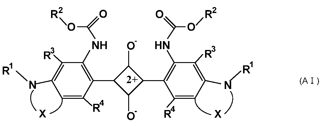
ただし、式(AI)中の記号は以下のとおりである。
Xは、独立して、1つ以上の水素原子が炭素数1~12のアルキル基またはアルコキシ基で置換されていてもよい式(1)または式(2)で示される2価の有機基である。
-(CH2)n1- …(1)
式(1)中、n1は2または3である。
-(CH2)n2-O-(CH2)n3- …(2)
式(2)中、n2とn3はそれぞれ独立して0~2の整数であり、n2+n3は1または2である。
R1は、独立して、飽和環構造を含んでもよく、分岐を有してもよい炭素数1~12の飽和もしくは不飽和炭化水素基、炭素数3~12の飽和環状炭化水素基、炭素数6~12のアリール基または炭素数7~13のアルアリール基を示す。
R2は、独立して、1つ以上の水素原子がハロゲン原子、水酸基、カルボキシ基、スルホ基、またはシアノ基で置換されていてもよく、炭素原子間に不飽和結合、酸素原子、飽和もしくは不飽和の環構造を含んでよい炭素数1~25の炭化水素基である。
R3およびR4は、独立して、水素原子、ハロゲン原子、または炭素数1~10のアルキル基もしくはアルコキシ基を示す。
また、本発明の他の態様に係る撮像装置は、上記光学フィルタを備えたことを特徴とする。
Xは、独立して、1つ以上の水素原子が炭素数1~12のアルキル基またはアルコキシ基で置換されていてもよい式(1)または式(2)で示される2価の有機基である。
-(CH2)n1- …(1)
式(1)中、n1は2または3である。
-(CH2)n2-O-(CH2)n3- …(2)
式(2)中、n2とn3はそれぞれ独立して0~2の整数であり、n2+n3は1または2である。
R1は、独立して、飽和環構造を含んでもよく、分岐を有してもよい炭素数1~12の飽和もしくは不飽和炭化水素基、炭素数3~12の飽和環状炭化水素基、炭素数6~12のアリール基または炭素数7~13のアルアリール基を示す。
R2は、独立して、1つ以上の水素原子がハロゲン原子、水酸基、カルボキシ基、スルホ基、またはシアノ基で置換されていてもよく、炭素原子間に不飽和結合、酸素原子、飽和もしくは不飽和の環構造を含んでよい炭素数1~25の炭化水素基である。
R3およびR4は、独立して、水素原子、ハロゲン原子、または炭素数1~10のアルキル基もしくはアルコキシ基を示す。
また、本発明の他の態様に係る撮像装置は、上記光学フィルタを備えたことを特徴とする。
本発明によれば、良好な近赤外線遮蔽特性を有しながら可視光透過率を高め、、基材や無機多層膜等との密着性、さらに耐光性に優れる吸収層を備えた光学フィルタが得られる。また、そのような光学フィルタを用いた信頼性の高い撮像装置が得られる。
以下、本発明の実施の形態について説明する。なお、以下の説明において、光学フィルタを「NIRフィルタ」、近赤外線吸収色素を「NIR吸収色素」または「NIR色素」、紫外線吸収色素を「UV吸収色素」または「UV色素」と略記することもある。
<NIRフィルタ>
本発明の一実施形態のNIRフィルタ(以下、「本フィルタ」という)は、第1の層と、この第1の層に接し、第1の層と異なる第2の層とを有する。
第1の層は、近赤外線吸収色素(A)と透明樹脂(B)とを含有する吸収層である。第2の層は、無機または有機材料からなる層で、例えば、ガラス基板や透明樹脂基板等を含む透明基材、特定の波長領域の光を遮蔽する誘電体多層膜からなる選択波長遮蔽層、可視域の透過率損失を抑制する誘電体多層膜からなる反射防止層等である。
第1の層および第2の層はそれぞれ本フィルタの中に1層有してもよく、2層以上有してもよい。2層以上有する場合、各層は同じ構成であっても異なってもよい。また、第1の層は、それそのものが基板(樹脂基板)として機能するものでもよい。
本発明の一実施形態のNIRフィルタ(以下、「本フィルタ」という)は、第1の層と、この第1の層に接し、第1の層と異なる第2の層とを有する。
第1の層は、近赤外線吸収色素(A)と透明樹脂(B)とを含有する吸収層である。第2の層は、無機または有機材料からなる層で、例えば、ガラス基板や透明樹脂基板等を含む透明基材、特定の波長領域の光を遮蔽する誘電体多層膜からなる選択波長遮蔽層、可視域の透過率損失を抑制する誘電体多層膜からなる反射防止層等である。
第1の層および第2の層はそれぞれ本フィルタの中に1層有してもよく、2層以上有してもよい。2層以上有する場合、各層は同じ構成であっても異なってもよい。また、第1の層は、それそのものが基板(樹脂基板)として機能するものでもよい。
本フィルタは、第1の層および第2の層以外の層、すなわち、第1の層と接しない第3の層を有してもよい。上記ガラス基板、樹脂基板等の透明基板、特定の波長領域の光を遮蔽する誘電体多層膜からなる選択波長遮蔽層、可視光の透過率損失を抑制する誘電体多層膜からなる反射防止層が第3の層として含まれてもよい。
以下、本フィルタの代表的な構成例を、図面を用いて説明する。
図1Aは、吸収層(第1の層)11の両主面に第2の層として誘電体多層膜からなる選択波長遮蔽層12を備えた構成例である。
図1Bは、吸収層(第1の層)11の両主面にそれぞれ第2の層として誘電体多層膜からなる選択波長遮蔽層12および誘電体多層膜からなる反射防止層13を備えた構成例である。
図1Cは、吸収層(第1の層)11の両主面にそれぞれ第2の層として透明基材14および誘電体多層膜からなる選択波長遮蔽層12を備えた構成例である。この例では、透明基材14の吸収層(第1の層)11とは反対側の主面に、さらに第3の層として誘電体多層膜からなる反射防止層13を備えている。
図1Dは、吸収層(第1の層)11の両主面にそれぞれ第2の層として透明基材14および誘電体多層膜からなる反射防止層13を備えた構成例である。この例では、透明基材14の吸収層(第1の層)11側とは反対側の主面に、さらに第3の層として誘電体多層膜からなる選択波長遮蔽層12を備えている。
図1Aは、吸収層(第1の層)11の両主面に第2の層として誘電体多層膜からなる選択波長遮蔽層12を備えた構成例である。
図1Bは、吸収層(第1の層)11の両主面にそれぞれ第2の層として誘電体多層膜からなる選択波長遮蔽層12および誘電体多層膜からなる反射防止層13を備えた構成例である。
図1Cは、吸収層(第1の層)11の両主面にそれぞれ第2の層として透明基材14および誘電体多層膜からなる選択波長遮蔽層12を備えた構成例である。この例では、透明基材14の吸収層(第1の層)11とは反対側の主面に、さらに第3の層として誘電体多層膜からなる反射防止層13を備えている。
図1Dは、吸収層(第1の層)11の両主面にそれぞれ第2の層として透明基材14および誘電体多層膜からなる反射防止層13を備えた構成例である。この例では、透明基材14の吸収層(第1の層)11側とは反対側の主面に、さらに第3の層として誘電体多層膜からなる選択波長遮蔽層12を備えている。
図1Aおよび図1Bにおいて、2層の選択波長遮蔽層12は、同一でも異なってもよい。例えば、一方の選択波長遮蔽層が、紫外光と第1の近赤外域の光を反射し、他方の選択波長遮蔽層12が、紫外光と第1の近赤外域と異なる第2の近赤外域の光を反射する構成でもよい。
本フィルタは、(iv-1)を満たす分光透過率特性を有することが好ましく、(iv-1)と、(iv-2)~(iv-6)の少なくとも一つを満たすことがより好ましい。(iv-1)~(iv-6)すべてを満たすことがとくに好ましい。
(iv-1)入射角0°の分光透過率曲線において、波長430~550nmの光の平均透過率が90%以上であり、かつ波長430~550nmの光の最小透過率が75%以上である。
(iv-2)入射角0°の分光透過率曲線において、波長600~700nmの光の平均透過率が25%以上である。
(iv-3)入射角0°の分光透過率曲線において、波長350~395nmの光の平均透過率が2%以下である。
(iv-4)入射角0°の分光透過率曲線において、波長710~1100nmの光の平均透過率が2%以下である。
(iv-5)入射角0°の分光透過率曲線の波長385~430nmの光の透過率と、入射角30°の分光透過率曲線における波長385~430nmの光の透過率との差分の絶対値の平均値(以下、「波長385~430nmの透過率平均シフト量」という)が7%/nm以下である。
(iv-6)入射角0°の分光透過率曲線の波長600~700nmの光の透過率と、入射角30°の分光透過率曲線における波長600~700nmの光の透過率との差分の絶対値の平均値(以下、「波長600~700nmの透過率平均シフト量」という)が7%/nm以下である。
(iv-2)入射角0°の分光透過率曲線において、波長600~700nmの光の平均透過率が25%以上である。
(iv-3)入射角0°の分光透過率曲線において、波長350~395nmの光の平均透過率が2%以下である。
(iv-4)入射角0°の分光透過率曲線において、波長710~1100nmの光の平均透過率が2%以下である。
(iv-5)入射角0°の分光透過率曲線の波長385~430nmの光の透過率と、入射角30°の分光透過率曲線における波長385~430nmの光の透過率との差分の絶対値の平均値(以下、「波長385~430nmの透過率平均シフト量」という)が7%/nm以下である。
(iv-6)入射角0°の分光透過率曲線の波長600~700nmの光の透過率と、入射角30°の分光透過率曲線における波長600~700nmの光の透過率との差分の絶対値の平均値(以下、「波長600~700nmの透過率平均シフト量」という)が7%/nm以下である。
(iv-1)を満たすことで、波長430~550nmの光の透過率を高くでき、青色系の撮像の色再現性の精度をさらに高くできる。
(iv-2)を満たすことで、固体撮像素子に不要な波長700nm以上の光を遮断しつつ、人間の視感度に関与する波長600~700nmの光の透過率を比較的高く維持できる。
(iv-3)を満たすことで、395nm以下の波長領域の光を遮蔽でき、固体撮像素子の分光感度を人間の視感度に近づけることができる。
(iv-4)を満たすことで、波長710~1100nmの光を遮蔽でき、固体撮像素子の分光感度を人間の視感度に近づけることができる。
(iv-5)を満たすことで、波長385~430nmにおける光の入射角依存性を小さくできる。その結果、この波長領域における固体撮像素子の分光感度の入射角依存性を小さくできる。
(iv-6)を満たすことで、波長600~700nmにおける光の入射角依存性を小さくできる。その結果、この波長領域における固体撮像素子の分光感度の入射角依存性を小さくできる。
(iv-2)を満たすことで、固体撮像素子に不要な波長700nm以上の光を遮断しつつ、人間の視感度に関与する波長600~700nmの光の透過率を比較的高く維持できる。
(iv-3)を満たすことで、395nm以下の波長領域の光を遮蔽でき、固体撮像素子の分光感度を人間の視感度に近づけることができる。
(iv-4)を満たすことで、波長710~1100nmの光を遮蔽でき、固体撮像素子の分光感度を人間の視感度に近づけることができる。
(iv-5)を満たすことで、波長385~430nmにおける光の入射角依存性を小さくできる。その結果、この波長領域における固体撮像素子の分光感度の入射角依存性を小さくできる。
(iv-6)を満たすことで、波長600~700nmにおける光の入射角依存性を小さくできる。その結果、この波長領域における固体撮像素子の分光感度の入射角依存性を小さくできる。
本フィルタは、入射角0°の分光透過率曲線において、波長430~550nmの光の平均透過率は91%以上がより好ましく、92%以上がより一層好ましい。光学フィルタの波長430~550nmの光の平均透過率が高いほど、可視光を多く取り込むことができる。
本フィルタは、入射角0°の分光透過率曲線において、波長430~550nmの光の最小透過率は、77%以上がより好ましく、80%以上がより一層好ましい。光学フィルタの波長430~550nmの光の最小透過率が高いほど、可視光を多く取り込むことができる。
本フィルタは、入射角0°の分光透過率曲線において、波長600~700nmの光の平均透過率は30%以上がより好ましい。光学フィルタの波長600~700nmの光の平均透過率が高いほど、視感度に不必要な波長700nm以上の光をより遮断しつつ、人間の視感度に関与する波長600~700nmの光の透過率をより高く維持できる。
本フィルタは、入射角0°の分光透過率曲線において、波長430~550nmの光の最小透過率は、77%以上がより好ましく、80%以上がより一層好ましい。光学フィルタの波長430~550nmの光の最小透過率が高いほど、可視光を多く取り込むことができる。
本フィルタは、入射角0°の分光透過率曲線において、波長600~700nmの光の平均透過率は30%以上がより好ましい。光学フィルタの波長600~700nmの光の平均透過率が高いほど、視感度に不必要な波長700nm以上の光をより遮断しつつ、人間の視感度に関与する波長600~700nmの光の透過率をより高く維持できる。
また、本フィルタは、入射角0°の分光透過率曲線において、波長430~480nmの光の平均透過率は87%以上が好ましく、88%以上がより好ましく、89%以上がより一層好ましく、90%以上がさらに好ましい。光学フィルタの波長430~480nmの光の平均透過率が高いほど、青色系の色再現性の精度を高められる。
本フィルタは、入射角0°の分光透過率曲線において、波長350~395nmの光の平均透過率は1.5%以下がより好ましく、1%以下がより一層好ましく、0.5%以下がさらに好ましい。光学フィルタの波長350~395nmの光の平均透過率が低いほど、固体撮像素子として不必要な波長の光を遮断できる。
本フィルタは、入射角0°の分光透過率曲線において、波長710~1100nmの光の平均透過率は1%以下がより好ましく、0.5%以下がより一層好ましく、0.3%以下がさらに好ましい。光学フィルタの波長710~1100nmの光の平均透過率が低いほど、固体撮像素子として不必要な波長の光を遮断できる。
本フィルタは、波長385~430nmの透過率平均シフト量が6%/nm以下がより好ましく、5%/nm以下がより一層好ましい。波長385~430nmの透過率平均シフト量は、波長385~430nmにおける本フィルタの光の入射角依存性を示す指標である。この値が小さいほど入射角依存性が低いことを示している。
本フィルタは、波長600~700nmの透過率平均シフト量が3%/nm以下がより好ましく、2%/nm以下がより一層好ましい。波長600~700nmの透過率平均シフト量は、波長600~700nmにおける本フィルタの光の入射角依存性を示す指標である。この値が小さいほど入射角依存性が低いことを示している。
本フィルタは、入射角0°の分光透過率曲線において、波長710~1100nmの光の平均透過率は1%以下がより好ましく、0.5%以下がより一層好ましく、0.3%以下がさらに好ましい。光学フィルタの波長710~1100nmの光の平均透過率が低いほど、固体撮像素子として不必要な波長の光を遮断できる。
本フィルタは、波長385~430nmの透過率平均シフト量が6%/nm以下がより好ましく、5%/nm以下がより一層好ましい。波長385~430nmの透過率平均シフト量は、波長385~430nmにおける本フィルタの光の入射角依存性を示す指標である。この値が小さいほど入射角依存性が低いことを示している。
本フィルタは、波長600~700nmの透過率平均シフト量が3%/nm以下がより好ましく、2%/nm以下がより一層好ましい。波長600~700nmの透過率平均シフト量は、波長600~700nmにおける本フィルタの光の入射角依存性を示す指標である。この値が小さいほど入射角依存性が低いことを示している。
次に、本フィルタを構成する吸収層、選択波長遮蔽層、反射防止層および透明基材について説明する。
[吸収層]
吸収層は、近赤外線吸収色素(A)と、透明樹脂(B)とを含有する層であり、典型的には、透明樹脂(B)中に近赤外線吸収色素(A)が均一に溶解または分散した層または(樹脂)基板である。吸収層は、さらに紫外線吸収色素(U)を含有してもよい。
本フィルタにおいて、吸収層は、前述のとおり、場合により複数設けてもよい。
吸収層は、近赤外線吸収色素(A)と、透明樹脂(B)とを含有する層であり、典型的には、透明樹脂(B)中に近赤外線吸収色素(A)が均一に溶解または分散した層または(樹脂)基板である。吸収層は、さらに紫外線吸収色素(U)を含有してもよい。
本フィルタにおいて、吸収層は、前述のとおり、場合により複数設けてもよい。
(近赤外線吸収色素(A))
本フィルタの吸収層に含有させる近赤外線吸収色素(A)(以下、NIR色素(A)ともいう)は、式(AI)で示されるNIR色素から選択される少なくとも1種を含む。
本フィルタの吸収層に含有させる近赤外線吸収色素(A)(以下、NIR色素(A)ともいう)は、式(AI)で示されるNIR色素から選択される少なくとも1種を含む。
本明細書において、式(AI)で示されるNIR色素を、NIR色素(AI)ともいう。他の色素についても同様である。また、後述するように、例えば、式(1n)で表される基を基(1n)と記す。他の式で表される基も同様に記す。
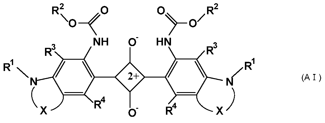
Xは、独立して、1つ以上の水素原子が炭素数1~12のアルキル基またはアルコキシ基で置換されていてもよい式(1)または式(2)で示される2価の有機基である。
-(CH2)n1- …(1)
式(1)中、n1は2または3である。
-(CH2)n2-O-(CH2)n3- …(2)
式(2)中、n2とn3はそれぞれ独立して0~2の整数であり、n2+n3は1または2である。
R1は、独立して、飽和環構造を含んでもよく、分岐を有してもよい炭素数1~12の飽和もしくは不飽和炭化水素基、炭素数3~12の飽和環状炭化水素基、炭素数6~12のアリール基または炭素数7~13のアルアリール基を示す。
R2は、独立して、1つ以上の水素原子がハロゲン原子、水酸基、カルボキシ基、スルホ基、またはシアノ基で置換されていてもよく、炭素原子間に不飽和結合、酸素原子、飽和もしくは不飽和の環構造を含んでよい炭素数1~25の炭化水素基である。
R3およびR4は、独立して、水素原子、ハロゲン原子、または炭素数1~10のアルキル基もしくはアルコキシ基を示す。
なお、本明細書において、飽和もしくは不飽和の環構造とは、炭化水素環および環構成原子として酸素原子を有するヘテロ環をいう。さらに、環を構成する炭素原子に炭素数1~10のアルキル基が結合した構造もその範疇に含むものとする。
また、アリール基は芳香族化合物が有する芳香環、例えば、ベンゼン環、ナフタレン環、ビフェニル、フラン環、チオフェン環、ピロール環等を構成する炭素原子を介して結合する基をいう。アルアリール基は、1以上のアリール基で置換された、飽和環構造を含んでもよい直鎖状もしくは分枝状の飽和もしくは不飽和炭化水素基または飽和環状炭化水素基をいう。
また、アリール基は芳香族化合物が有する芳香環、例えば、ベンゼン環、ナフタレン環、ビフェニル、フラン環、チオフェン環、ピロール環等を構成する炭素原子を介して結合する基をいう。アルアリール基は、1以上のアリール基で置換された、飽和環構造を含んでもよい直鎖状もしくは分枝状の飽和もしくは不飽和炭化水素基または飽和環状炭化水素基をいう。
NIR色素(AI)は、分子構造の中央にスクアリリウム骨格を有し、スクアリリウム骨格の左右に各1個のベンゼン環が結合し、そのベンゼン環は4位で窒素原子と結合し、該窒素原子とベンゼン環の4位と5位の炭素原子を含む複素環が形成された縮合環構造を左右に有する。さらに、NIR色素(AI)は、左右の各1個のベンゼン環の2位でそれぞれ式(a1)で示されるウレタン基と結合する。
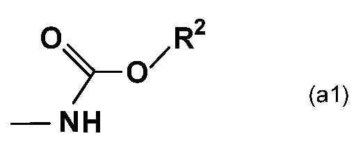
NIR色素(AI)において、左右に1個ずつ存在する縮合環構造を構成するベンゼン環以外の環の構成は、上記Xにより決定され、それぞれ独立して員数が5または6の複素環である。前記複素環の一部を構成する2価の基Xは、式(1)で示されるように骨格が炭素原子のみで構成されてもよく、式(2)で示されるように炭素原子以外に酸素原子を含んでもよい。式(2)において、酸素原子の位置はとくに制限されない。すなわち、窒素原子と酸素原子が結合してもよく、ベンゼン環に酸素原子が直接結合してもよい。また、炭素原子に挟まれるように酸素原子が位置してもよい。
なお、左右のXは同一であっても異なってもよいが、生産性の観点から同一が好ましい。またR1~R4についても、スクアリリウム骨格を挟んで左右で同一であっても異なってもよいが、生産性の観点から同一が好ましい。
NIR色素(AI)は、上記のように、スクアリリウム骨格の左右に結合するベンゼン環の2位にウレタン基が結合しており、これにより、従来のスクアリリウム系色素と同等もしくはそれ以上の近赤外域および可視域での分光透過率特性を有しながら、該NIR色素(AI)を含む吸収層に接する層として、有機材料からなる層だけでなく、とくにガラスや誘電体多層膜等の無機材料からなる層に対する密着性を高められる。これは、ウレタン基を含有することでNIR色素自体の極性が上がり、NIR色素とガラス等の無機材料との化学的相互作用が増大するからと考えられる。
また、このようにNIR色素(AI)はウレタン基を有するため、吸収層の耐光性を高め、光学フィルタに良好な耐光性を付与できる。なお、光学フィルタの耐光性は、例えば、光学フィルタに一定時間、光を照射し、その前後の所定の波長領域における最大透過率の変動量から評価でき、この最大透過率変動量が小さいほど耐光性に優れている。
照射装置:キセノンランプ(波長300~2450nm)
温度:40℃
湿度:50%RT
積算光量:87.2kw・時間/m2
照射装置:キセノンランプ(波長300~2450nm)
温度:40℃
湿度:50%RT
積算光量:87.2kw・時間/m2
さらに、NIR色素(AI)は、有機溶媒に対する溶解性が良好で、したがって、透明樹脂への相溶性も良好である。その結果、吸収層の厚さを薄くしても優れた分光特性を有し、光学フィルタを小型化、薄型化できる。また、NIR色素(AI)は、吸収層の厚さを薄くできるため、加熱による吸収層の熱膨張を抑制でき、選択波長遮蔽層や他の機能層、例えば反射防止層を形成する際の、それらの層の割れ等の発生を抑制できる。
なお、有機溶媒に対する溶解性、透明樹脂への相溶性の観点から、置換基R1は、分岐構造を有する基が好ましく、分岐構造を有するアルキル基またはアルコキシ基がより好ましい。
なお、有機溶媒に対する溶解性、透明樹脂への相溶性の観点から、置換基R1は、分岐構造を有する基が好ましく、分岐構造を有するアルキル基またはアルコキシ基がより好ましい。
NIR色素(AI)のXは、式(3)で示される2価の有機基が好ましい。
-CR5 2-(CR6 2)n4- …(3)
ただし、式(3)は、左側がベンゼン環に結合し右側がNに結合する2価の基を示し、n4は1または2である。n4は1が好ましい。また、R5は、それぞれ独立して、分岐を有してもよい炭素数1~12のアルキル基またはアルコキシ基であり、炭素数1~6の分岐を有してもよいアルキル基またはアルコキシ基が好ましい。さらに、R6はそれぞれ独立して、水素原子、または分岐を有してもよい炭素数1~12のアルキル基もしくはアルコキシ基であり、水素原子、または分岐を有してもよい炭素数1~6のアルキル基またはアルコキシ基が好ましい。
-CR5 2-(CR6 2)n4- …(3)
ただし、式(3)は、左側がベンゼン環に結合し右側がNに結合する2価の基を示し、n4は1または2である。n4は1が好ましい。また、R5は、それぞれ独立して、分岐を有してもよい炭素数1~12のアルキル基またはアルコキシ基であり、炭素数1~6の分岐を有してもよいアルキル基またはアルコキシ基が好ましい。さらに、R6はそれぞれ独立して、水素原子、または分岐を有してもよい炭素数1~12のアルキル基もしくはアルコキシ基であり、水素原子、または分岐を有してもよい炭素数1~6のアルキル基またはアルコキシ基が好ましい。
式(AI)におけるXとしては、式(11-1)~(12-3)で示される2価の有機基のいずれかがとくに好ましい。ただし、式(11-1)~(12-3)は、いずれも左側がベンゼン環に結合し右側がNに結合する2価の基を示す。
-C(CH3)2-CH(CH3)- …(11-1)
-C(CH3)2-CH2- …(11-2)
-C(CH3)2-CH(C2H5)- …(11-3)
-C(CH3)2-CH2-CH2- …(12-1)
-C(CH3)2-CH2-CH(CH3)- …(12-2)
-C(CH3)2-CH(CH3)-CH2- …(12-3)
-C(CH3)2-CH(CH3)- …(11-1)
-C(CH3)2-CH2- …(11-2)
-C(CH3)2-CH(C2H5)- …(11-3)
-C(CH3)2-CH2-CH2- …(12-1)
-C(CH3)2-CH2-CH(CH3)- …(12-2)
-C(CH3)2-CH(CH3)-CH2- …(12-3)
これらのうちでも、式(AI)におけるXとしては、基(11-1)~(11-3)のいずれかが好ましく、基(11-1)がより好ましい。
以下に、Xが左右ともに基(11-1)であるNIR色素(Ai)の構造式を示す。なお、NIR色素(Ai)中、R1~R4はNIR色素(AI)におけるR1~R4と同じ意味である。

以下に、Xが左右ともに基(11-1)であるNIR色素(Ai)の構造式を示す。なお、NIR色素(Ai)中、R1~R4はNIR色素(AI)におけるR1~R4と同じ意味である。
また、NIR色素(AI)中、R1は、分光透過率曲線における可視域と近赤外域の境界付近の変化の急峻性、また、溶解性、耐熱性等の観点から、独立して、式(4-1)または式(4-2)で示される基がより好ましい。

式(4-1)および式(4-2)中、R7、R8、R9、R10およびR11は、独立して、水素原子、ハロゲン原子、または炭素数1~4のアルキル基を示す。
また、NIR色素(AI)中、R3およびR4は、独立して、水素原子、ハロゲン原子、または炭素数1~6のアルキル基もしくはアルコキシ基が好ましい。R3およびR4は、いずれも水素原子がより好ましい。
NIR色素(AI)としては、NIR色素(Ai)が好ましく、中でも、表1に示す構成のNIR色素(A1-1)~(A1-13)がより好ましい。さらに、色素の溶解性の観点から、NIR色素(A1-2)~(A1-4)、(A1-6)~(A1-8)、(A1-10)~(A1-13)がとくに好ましい。なお、NIR色素(A1-1)~(A1-13)において、左右に1個ずつ計2個存在するR1は左右で同じであり、R2~R4についても同様である。

NIR色素(AI)は、例えば、国際公開第14/088063号明細書に記載された方法で製造可能である。具体的にNIR色素(AI)は、3,4-ジヒドロキシ-3-シクロブテン-1,2-ジオン(スクアリン酸)と、スクアリン酸と結合して式(AI)に示す構造を形成可能な縮合環を有する化合物とを反応させることで製造できる。例えば、NIR色素(AI)が左右対称の構造である場合には、スクアリン酸1当量に対して上記範囲で所望の構造の縮合環を有する化合物2当量を反応させればよい。
以下に、具体例として、NIR色素(Ai)を得る際の反応経路を示す。反応式(F1)においてスクアリン酸を(s)で示す。反応式(F1)によれば、インドール骨格に所望の置換基(R1、R3、R4)を有する化合物(d)の、ベンゼン環にアミノ基を導入し(f)、さらに所望の置換基R2を有するクロロギ酸エステル(g)を反応させてウレタン化合物(h)を得る。スクアリン酸(s)1当量に対し、ウレタン化合物(h)2当量を反応させて、NIR色素(Ai)を得る。

反応式(F1)中、R1~R4は、式(Ai)におけるR1~R4と同じ意味であり、Meはメチル基、THFはテトラヒドロフランを示す。以下、本明細書中、Me、THFは前記と同じ意味で用いられる。
本実施形態において、NIR色素(AI)は、ジクロロメタンに溶解して測定される吸収特性が、(i-1)~(i-3)を満たすものが好ましい。
(i-1)波長400~800nmの吸収スペクトルにおいて、670~730nm、好ましくは680~720nm、より好ましくは690~710nmの波長領域に最大吸収波長λmaxを有する。
(i-2)波長430~550nmの光の最大吸光係数εAと、波長670~730nmの光の最大吸光係数εBとの間に、次の関係式が成り立つ。
εB/εA≧50
この関係式は、好ましくはεB/εA≧60であり、より好ましくはεB/εA≧70である。
(i-3)分光透過率曲線において、前記最大吸収波長λmaxにおける透過率を10%としたときの前記最大吸収波長λmaxより短波長側で透過率が80%となる波長λ80と、前記最大吸収波長λmaxとの差λmax-λ80が60nm以下である。λmax-λ80は、好ましくは55nm以下、より好ましくは50nm以下である。
(i-1)波長400~800nmの吸収スペクトルにおいて、670~730nm、好ましくは680~720nm、より好ましくは690~710nmの波長領域に最大吸収波長λmaxを有する。
(i-2)波長430~550nmの光の最大吸光係数εAと、波長670~730nmの光の最大吸光係数εBとの間に、次の関係式が成り立つ。
εB/εA≧50
この関係式は、好ましくはεB/εA≧60であり、より好ましくはεB/εA≧70である。
(i-3)分光透過率曲線において、前記最大吸収波長λmaxにおける透過率を10%としたときの前記最大吸収波長λmaxより短波長側で透過率が80%となる波長λ80と、前記最大吸収波長λmaxとの差λmax-λ80が60nm以下である。λmax-λ80は、好ましくは55nm以下、より好ましくは50nm以下である。
(i-1)~(i-3)を満たすNIR色素(A)を使用することにより、目的とする、良好な近赤外線遮蔽特性を有しながら、当接する層との密着性に優れる高信頼性の光学フィルタが得られる。
具体的には、(i-1)を満たすことで、近赤外光を十分に遮蔽できる。また、(i-2)を満たすことで、可視光を十分に透過できる。さらに、(i-3)を満たすことで、分光透過率曲線において、可視域と近赤外域の境界付近(透過率遷移領域)の変化を急峻にできる。
具体的には、(i-1)を満たすことで、近赤外光を十分に遮蔽できる。また、(i-2)を満たすことで、可視光を十分に透過できる。さらに、(i-3)を満たすことで、分光透過率曲線において、可視域と近赤外域の境界付近(透過率遷移領域)の変化を急峻にできる。
本実施形態において、NIR色素(A)には、本発明の効果を阻害しない範囲であれば、必要に応じて、NIR色素(AI)以外の色素を含有してもよい。密着性の観点からは、NIR色素(AI)のみを使用することが好ましい。
吸収層中におけるNIR色素(A)の含有量は、透明樹脂(B)100質量部に対して、0.1~30質量部が好ましい。0.1質量部以上とすることで所望の近赤外線吸収能が得られ、30質量部以下とすることで、近赤外線吸収能の低下やヘイズ値の上昇等が抑制される。NIR色素(A)の含有量は、0.5~25質量部がより好ましく、1~20質量部がより一層好ましい。
(紫外線吸収色素(U))
吸収層は、NIR色素(A)と、透明樹脂に加え、UV色素(U)を含有できる。UV色素(U)(以下、色素(U)ともいう。)としては、(ii-1)を満たすものが好ましい。
吸収層は、NIR色素(A)と、透明樹脂に加え、UV色素(U)を含有できる。UV色素(U)(以下、色素(U)ともいう。)としては、(ii-1)を満たすものが好ましい。
(ii-1)ジクロロメタンに溶解して測定される波長350~800nmの吸収スペクトル(以下、「UV色素(U)の吸収スペクトル」という)において、360~415nmの波長領域に最大吸収波長を有する。
(ii-1)を満たすUV色素(U)を使用すれば、最大吸収波長が適切かつ急峻な吸収スペクトルの立ち上がりをもつので430nm以降の透過率を低下させずに良好な紫外線遮蔽特性が得られる。
UV色素(U)の吸収スペクトルにおいて、UV色素(U)の最大吸収波長は370~415nmの波長領域にあるとより好ましく、390~410nmの波長領域にあるとより一層好ましい。
UV色素(U)の吸収スペクトルにおいて、UV色素(U)の最大吸収波長は370~415nmの波長領域にあるとより好ましく、390~410nmの波長領域にあるとより一層好ましい。
本実施形態に好適な、(ii-1)を満たしているUV色素(以下、UV色素(U1)という)の具体例としては、オキサゾール系、メロシアニン系、シアニン系、ナフタルイミド系、オキサジアゾール系、オキサジン系、オキサゾリジン系、ナフタル酸系、スチリル系、アントラセン系、環状カルボニル系、トリアゾール系等の色素が挙げられる。
UV色素(U1)として、式(N)で示されるUV色素(UV色素(N))も挙げられる。

式(N)中、R12は、それぞれ独立に、飽和もしくは不飽和の環構造を含んでもよく、分岐を有してもよい炭素数1~20の炭化水素基を示す。具体的には、直鎖状または分枝状のアルキル基、アルケニル基、飽和環状炭化水素基、アリール基、アルアリール基等が挙げられる。
また、式(N)中、R13は、それぞれ独立に、シアノ基、または式(n)で示される基である。
-COOR30 …(n)
式(n)中、R30は、飽和もしくは不飽和の環構造を含んでもよく、分岐を有してもよい炭素数1~20の炭化水素基を示す。具体的には、直鎖状または分枝鎖状のアルキル基、アルケニル基、飽和環状炭化水素基、アリール基、アルアリール基等が挙げられる。
また、式(N)中、R13は、それぞれ独立に、シアノ基、または式(n)で示される基である。
-COOR30 …(n)
式(n)中、R30は、飽和もしくは不飽和の環構造を含んでもよく、分岐を有してもよい炭素数1~20の炭化水素基を示す。具体的には、直鎖状または分枝鎖状のアルキル基、アルケニル基、飽和環状炭化水素基、アリール基、アルアリール基等が挙げられる。
UV色素(N)中のR12としては、式(1n)~(4n)で示される基が中でも好ましい。また、UV色素(N)中のR13としては、式(5n)で示される基が中でも好ましい。

UV色素(N)としては、表2に示す構成のUV色素(N-1)~(N-4)が例示できる。なお、表2におけるR12およびR13の具体的な構造は、式(1n)~(5n)に対応する。表2には対応する色素略号も示した。なお、UV色素(N-1)~(N-4)において、2個存在するR12は同じであり、R13も同様である。

以上例示したUV色素(U1)の中でも、オキサゾール系、メロシアニン系の色素が好ましく、その市販品としては、例えば、Uvitex(登録商標)OB、Hakkol(登録商標)RF-K、S0511が挙げられる。
(メロシアニン系色素)
UV色素(U1)としては、とくに、式(M)で示されるメロシアニン系色素が好ましい。
UV色素(U1)としては、とくに、式(M)で示されるメロシアニン系色素が好ましい。

Q1は、置換基を有していてもよい炭素数1~12の1価の炭化水素基を表す。置換基を有しない1価の炭化水素基としては、水素原子の一部が脂肪族環、芳香族環もしくはアルケニル基で置換されていてもよい炭素数1~12のアルキル基、水素原子の一部が芳香族環、アルキル基もしくはアルケニル基で置換されていてもよい炭素数3~8のシクロアルキル基、および水素原子の一部が脂肪族環、アルキル基もしくはアルケニル基で置換されていてもよい炭素数6~12のアリール基が好ましい。
Q1が無置換のアルキル基である場合、そのアルキル基は直鎖状であっても、分岐状であってもよく、その炭素数は1~6がより好ましい。
Q1が無置換のアルキル基である場合、そのアルキル基は直鎖状であっても、分岐状であってもよく、その炭素数は1~6がより好ましい。
水素原子の一部が脂肪族環、芳香族環もしくはアルケニル基で置換された炭素数1~12のアルキル基としては、炭素数3~6のシクロアルキル基を有する炭素数1~4のアルキル基、フェニル基で置換された炭素数1~4のアルキル基がより好ましく、フェニル基で置換された炭素数1または2のアルキル基がとくに好ましい。なお、アルケニル基で置換されたアルキル基とは、全体としてアルケニル基であるが1、2位間に不飽和結合を有しないものを意味し、例えばアリル基や3-ブテニル基等をいう。
置換基を有する炭化水素基としては、アルコキシ基、アシル基、アシルオキシ基、シアノ基、ジアルキルアミノ基または塩素原子を1個以上有する炭化水素基が好ましい。これらアルコキシ基、アシル基、アシルオキシ基およびジアルキルアミノ基の炭素数は1~6が好ましい。
置換基を有する炭化水素基としては、アルコキシ基、アシル基、アシルオキシ基、シアノ基、ジアルキルアミノ基または塩素原子を1個以上有する炭化水素基が好ましい。これらアルコキシ基、アシル基、アシルオキシ基およびジアルキルアミノ基の炭素数は1~6が好ましい。
好ましいQ1は、水素原子の一部がシクロアルキル基またはフェニル基で置換されていてもよい炭素数1~6のアルキル基である。
とくに好ましいQ1は炭素数1~6のアルキル基であり、具体的には、例えば、メチル基、エチル基、プロピル基、イソプロピル基、ブチル基、イソブチル基、t-ブチル基等が挙げられる。
とくに好ましいQ1は炭素数1~6のアルキル基であり、具体的には、例えば、メチル基、エチル基、プロピル基、イソプロピル基、ブチル基、イソブチル基、t-ブチル基等が挙げられる。
Q2~Q5は、それぞれ独立に、水素原子、ハロゲン原子、または、炭素数1~10のアルキル基もしくはアルコキシ基を表す。アルキル基及びアルコキシ基の炭素数は1~6が好ましく、1~4がより好ましい。
Q2およびQ3は、少なくとも一方がアルキル基であることが好ましく、いずれもアルキル基であることがより好ましい。Q2またはQ3がアルキル基でない場合は、水素原子であることがより好ましい。Q2およびQ3は、いずれも炭素数1~6のアルキル基であることがとくに好ましい。
Q4およびQ5は、少なくとも一方が水素原子であることが好ましく、いずれも水素原子であることがより好ましい。Q4またはQ5が水素原子でない場合は、炭素数1~6のアルキル基であることが好ましい。
Q2およびQ3は、少なくとも一方がアルキル基であることが好ましく、いずれもアルキル基であることがより好ましい。Q2またはQ3がアルキル基でない場合は、水素原子であることがより好ましい。Q2およびQ3は、いずれも炭素数1~6のアルキル基であることがとくに好ましい。
Q4およびQ5は、少なくとも一方が水素原子であることが好ましく、いずれも水素原子であることがより好ましい。Q4またはQ5が水素原子でない場合は、炭素数1~6のアルキル基であることが好ましい。
Zは、式(Z1)~(Z5)で表される2価の基のいずれかを表す。
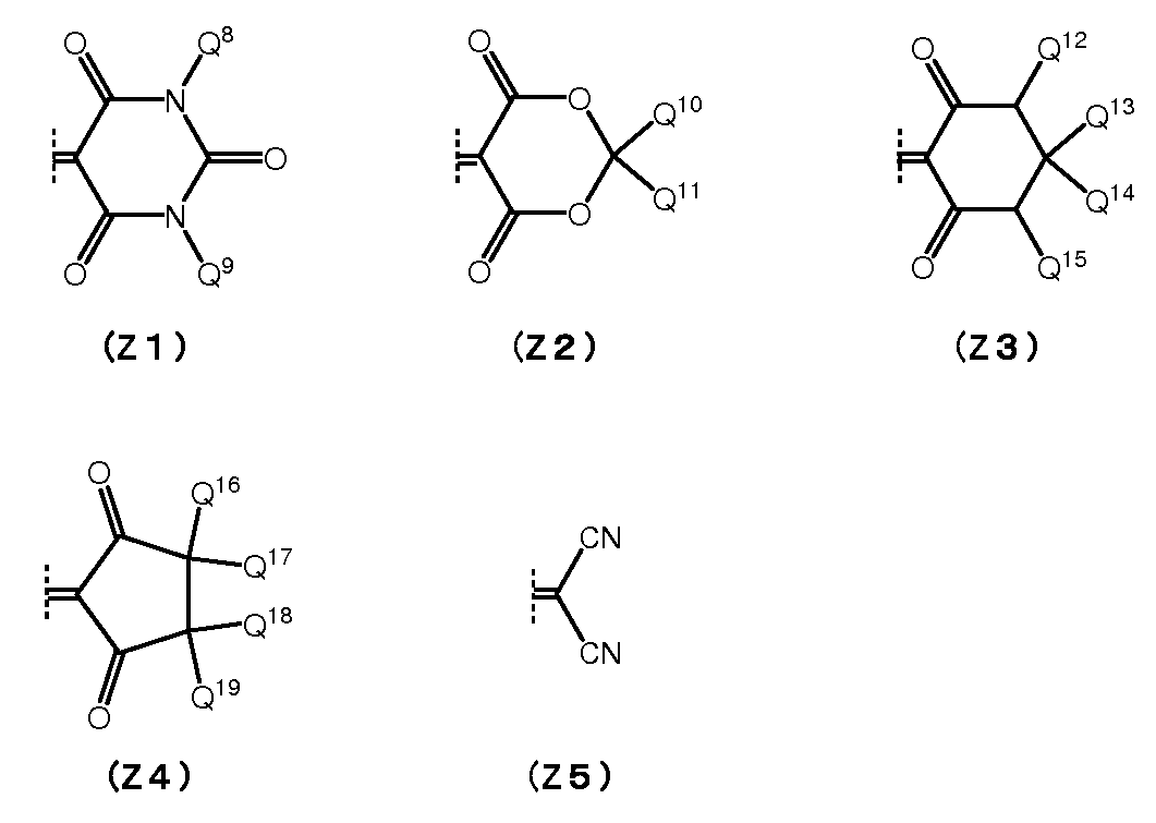
式(Z1)~(Z5)において、Q8およびQ9は、それぞれ独立に、置換基を有していてもよい炭素数1~12の1価の炭化水素基を表す。Q8およびQ9は、異なる基であってもよいが、同一の基であることが好ましい。
置換基を有しない1価の炭化水素基としては、水素原子の一部が脂肪族環、芳香族環もしくはアルケニル基で置換されていてもよい炭素数1~12のアルキル基、水素原子の一部が芳香族環、アルキル基もしくはアルケニル基で置換されていてもよい炭素数3~8のシクロアルキル基、および、水素原子の一部が脂肪族環、アルキル基もしくはアルケニル基で置換されていてもよい炭素数6~12のアリール基が好ましい。
Q8およびQ9が無置換のアルキル基である場合、そのアルキル基は直鎖状であっても、分岐状であってもよく、その炭素数は1~6がより好ましい。
水素原子の一部が脂肪族環、芳香族環もしくはアルケニル基で置換された炭素数1~12のアルキル基としては、炭素数3~6のシクロアルキル基を有する炭素数1~4のアルキル基、フェニル基で置換された炭素数1~4のアルキル基がより好ましく、フェニル基で置換された炭素数1または2のアルキル基がとくに好ましい。なお、アルケニル基で置換されたアルキル基とは、全体としてアルケニル基であるが1、2位間に不飽和結合を有しないものを意味し、例えばアリル基や3-ブテニル基等をいう。
水素原子の一部が脂肪族環、芳香族環もしくはアルケニル基で置換された炭素数1~12のアルキル基としては、炭素数3~6のシクロアルキル基を有する炭素数1~4のアルキル基、フェニル基で置換された炭素数1~4のアルキル基がより好ましく、フェニル基で置換された炭素数1または2のアルキル基がとくに好ましい。なお、アルケニル基で置換されたアルキル基とは、全体としてアルケニル基であるが1、2位間に不飽和結合を有しないものを意味し、例えばアリル基や3-ブテニル基等をいう。
置換基を有する1価の炭化水素基としては、アルコキシ基、アシル基、アシルオキシ基、シアノ基、ジアルキルアミノ基または塩素原子を1個以上有する炭化水素基が好ましい。これらアルコキシ基、アシル基、アシルオキシ基およびジアルキルアミノ基の炭素数は1~6が好ましい。
好ましいQ8およびQ9は、いずれも、水素原子の一部がシクロアルキル基またはフェニル基で置換されていてもよい炭素数1~6のアルキル基である。
とくに好ましいQ8およびQ9は、いずれも、炭素数1~6のアルキル基であり、具体的には、例えば、メチル基、エチル基、プロピル基、イソプロピル基、ブチル基、イソブチル基、t-ブチル基等が挙げられる。
とくに好ましいQ8およびQ9は、いずれも、炭素数1~6のアルキル基であり、具体的には、例えば、メチル基、エチル基、プロピル基、イソプロピル基、ブチル基、イソブチル基、t-ブチル基等が挙げられる。
Q10~Q19は、それぞれ独立に、水素原子、または、置換基を有していてもよい炭素数1~12の1価の炭化水素基を表す。置換基を有していてもよい炭素数1~12の1価の炭化水素基は、前記Q8、Q9と同様の炭化水素基である。置換基を有していてもよい炭素数1~12の1価の炭化水素基としては、置換基を有しない炭素数1~6のアルキル基が好ましい。
Q10とQ11は、いずれも、炭素数1~6のアルキル基であることがより好ましく、それらは同一のアルキル基であることがとくに好ましい。
Q12、Q15は、いずれも水素原子であるか、置換基を有しない炭素数1~6のアルキル基であることが好ましい。同じ炭素原子に結合した2つの基(Q13とQ14、Q16とQ17、Q18とQ19)は、いずれも水素原子であるか、いずれも炭素数1~6のアルキル基であることが好ましい。
Q12、Q15は、いずれも水素原子であるか、置換基を有しない炭素数1~6のアルキル基であることが好ましい。同じ炭素原子に結合した2つの基(Q13とQ14、Q16とQ17、Q18とQ19)は、いずれも水素原子であるか、いずれも炭素数1~6のアルキル基であることが好ましい。
式(M)で表される化合物としては、Yが酸素原子であり、Zが基(Z1)または基(Z2)である化合物、および、YがQ6およびQ7で置換されたメチレン基であり、Zが基(Z1)または基(Z5)である化合物が好ましい。
Yが酸素原子である場合のZとしては、Q1が炭素数1~6のアルキル基、Q2とQ3がいずれも水素原子であるかいずれも炭素数炭素数1~6のアルキル基、Q4、Q5がいずれも水素原子ある、基(Z1)または基(Z2)がより好ましい。とくに、Q1が炭素数1~6のアルキル基、Q2とQ3がいずれも炭素数1~6のアルキル基、Q4、Q5がいずれも水素原子ある、基(Z1)または基(Z2)が好ましい。
Yが酸素原子である場合のZとしては、Q1が炭素数1~6のアルキル基、Q2とQ3がいずれも水素原子であるかいずれも炭素数炭素数1~6のアルキル基、Q4、Q5がいずれも水素原子ある、基(Z1)または基(Z2)がより好ましい。とくに、Q1が炭素数1~6のアルキル基、Q2とQ3がいずれも炭素数1~6のアルキル基、Q4、Q5がいずれも水素原子ある、基(Z1)または基(Z2)が好ましい。
YがQ6およびQ7で置換されたメチレン基であり、Zが基(Z1)または基(Z5)である化合物としては、Q1が炭素数1~6のアルキル基、Q2とQ3がいずれも水素原子であるかいずれも炭素数1~6のアルキル基、Q4~Q7がいずれも水素原子ある、基(Z1)または基(Z5)が好ましく、Q1が炭素数1~6のアルキル基、Q2~Q7がいずれも水素原子ある、基(Z1)または基(Z5)がより好ましい。
式(M)で表される化合物としては、Yが酸素原子であり、Zが基(Z1)または基(Z2)である化合物が好ましく、Yが酸素原子であり、Zが基(Z1)である化合物がとくに好ましい。
式(M)で表される化合物としては、Yが酸素原子であり、Zが基(Z1)または基(Z2)である化合物が好ましく、Yが酸素原子であり、Zが基(Z1)である化合物がとくに好ましい。
UV色素(M)の具体例としては、以下の式(M-1)~(M-11)で表される化合物が挙げられる。


UV色素(U)は、好ましくはUV色素(U1)の1種または2種以上を含有する。UV色素(U)は、UV色素(U1)以外に、その他の紫外線吸収色素を含有してもよい。しかし、その場合、UV色素(U1)による効果を損なわない範囲が好ましい。
吸収層中におけるUV色素(U)の含有量は、本フィルタの入射角0°の分光透過率曲線の波長400~425nmに透過率が50%となる波長を有するように定めることが好ましい。UV色素(U)は、吸収層中において、透明樹脂の100質量部に対して、0.01~30質量部含有するのが好ましく、0.05~25質量部がより好ましく、0.1~20質量部がより一層好ましい。
(透明樹脂(B))
透明樹脂(B)としては、例えば、アクリル樹脂、エポキシ樹脂、エン・チオール樹脂、ポリカーボネート樹脂、ポリエーテル樹脂、ポリアリレート樹脂、ポリスルホン樹脂、ポリエーテルスルホン樹脂、ポリパラフェニレン樹脂、ポリアリーレンエーテルフォスフィンオキシド樹脂、ポリイミド樹脂、ポリアミドイミド樹脂、ポリオレフィン樹脂、環状オレフィン樹脂、ポリエステル樹脂が挙げられる。これらの樹脂は1種を単独で使用してもよく、2種以上を混合して使用してもよい。
透明樹脂(B)としては、上述した樹脂の中でも、可視光に対する透明性や、NIR色素(A)または、NIR色素(A)およびUV色素(U)の、透明樹脂(B)に対する溶解性、および耐熱性等の観点からは、ガラス転移点(Tg)の高い樹脂が好ましい。具体的には、ポリエステル樹脂、ポリカーボネート樹脂、ポリエーテルスルホン樹脂、ポリアリレート樹脂、ポリイミド樹脂、およびエポキシ樹脂から選ばれる1種以上が好ましい。さらに、透明樹脂(B)は、ポリエステル樹脂、ポリイミド樹脂から選ばれる1種以上がより好ましい。ポリエステル樹脂としては、ポリエチレンテレフタレート樹脂、ポリエチレンナフタレート樹脂等が好ましい。なお、ガラス転移点(Tg)の高い樹脂は、一般に、ガラスや誘電体多層膜等の無機材料からなる層に対し、密着性が低いが、本発明においては、上記NIR色素(AI)を使用したことにより、それらの層に対しても十分な密着性を確保できる。
なお、透明樹脂(B)としては、市販品を用いてもよい。市販品としては、アクリル樹脂として、オグソール(登録商標)EA-F5003(大阪ガスケミカル(株)製、商品名)、ポリメチルメタクリレート、ポリイソブチルメタクリレート(以上、いずれも東京化成工業(株)製、商品名)、BR50(三菱レイヨン(株)製、商品名)等が挙げられる。
また、ポリエステル樹脂として、OKP4HT、OKP4、B-OKP2、OKP-850(以上、いずれも大坂ガスケミカル(株)製、商品名)、バイロン(登録商標)103(東洋紡(株)製、商品名)等、ポリエーテルスルホン樹脂として、スミカエクセル(登録商標)PES4800(住友化学(株)製、商品名)等、ポリカーボネート樹脂として、LeXan(登録商標)ML9103(sabic社製、商品名)、EP5000(三菱ガス化学(株)社製、商品名)、SP3810(帝人化成(株)製、商品名)、SP1516(帝人化成(株)製、商品名)、TS2020(帝人化成(株)製、商品名)、xylex(登録商標)7507(sabic社製、商品名)等、環状オレフィン樹脂として、ARTON(登録商標)(JSR(株)製、商品名)、ZEONEX(登録商標)(日本ゼオン(株)製、商品名)等、ポリイミド樹脂として、ネオプリム(登録商標)C3650(三菱ガス化学(株)製、商品名)、同C3630(三菱ガス化学(株)製、商品名)、同C3450(三菱ガス化学(株)製、商品名)(これらのポリイミド樹脂には、シリカが含まれていてもよい)等が挙げられる。
(その他の成分)
吸収層には、さらに、本発明の効果を損なわない範囲で、この種の吸収層が通常含有する各種任意成分を含有してもよい。任意成分としては、例えば、密着性付与剤、色調補正色素、レベリング剤、帯電防止剤、熱安定剤、光安定剤、酸化防止剤、分散剤、難燃剤、滑剤、可塑剤等が挙げられる。
吸収層には、さらに、本発明の効果を損なわない範囲で、この種の吸収層が通常含有する各種任意成分を含有してもよい。任意成分としては、例えば、密着性付与剤、色調補正色素、レベリング剤、帯電防止剤、熱安定剤、光安定剤、酸化防止剤、分散剤、難燃剤、滑剤、可塑剤等が挙げられる。
密着性付与剤としては、ビニル基、エポキシ基、スチリル基、メタクリル基、アクリル基、アミノ基、ウレイド基、メルカプト基、スルフィド基およびイソシアネート基からなる群より選択される少なくとも1種を有するシランンカップリング剤が好適である。
NIR色素(A)、UV色素(U)、透明樹脂(B)等を溶解または分散するための溶媒としては、これらを、安定に分散できる分散媒または溶解できる溶媒であれば、とくに限定されない。なお、本明細書において「溶媒」の用語は、分散媒および溶媒の両方を含む概念で用いられる。溶媒は1種を単独で、または2種以上を混合して使用できる。
溶媒の量は、塗工液の塗工方法にもよるが、一般には、塗工液中の透明樹脂(B)、NIR色素(A)等の固形分濃度が、塗工液全量に対して2~50質量%となる範囲が好ましく、5~40質量%となる範囲がより好ましい。固形分濃度が低すぎると、塗工ムラが生じやすくなる。逆に、固形分濃度が高すぎると、塗工外観が不良となりやすくなる。
塗工液には、界面活性剤も含有できる。界面活性剤を含有させることにより、外観、とくに、微小な泡によるボイド、異物等の付着による凹み、乾燥工程でのはじきを改善できる。界面活性剤は、とくに限定されず、カチオン系、アニオン系、ノニオン系等の公知のものを任意に使用できる。
塗工液の塗工には、例えば、浸漬コーティング法、キャストコーティング法、スプレーコーティング法、スピンナーコーティング法、ビードコーティング法、ワイヤーバーコーティング法、ブレードコーティング法、ローラーコーティング法、カーテンコーティング法、スリットダイコーター法、グラビアコーター法、スリットリバースコーター法、マイクログラビア法、インクジェット法、またはコンマコーター法等のコーティング法を使用できる。その他、バーコーター法、スクリーン印刷法、フレキソ印刷法等も使用できる。
なお、本フィルタが構成部材としてガラス基板等を含む透明基材を備える場合であっても、上記塗工液を透明基材とは別の基材、例えば剥離性の支持基材上に塗工して形成した吸収層を、支持基材から剥離して透明基材上に貼着してもよい。剥離性の支持基材は、フィルム状であっても板状であってもよく、剥離性を有するものであれば、材料もとくに限定されない。具体的には、ガラス板や、離型処理されたプラスチックフィルム、ステンレス鋼板等が使用できる。
また、吸収層は、透明樹脂の種類によっては、押出成形によりフィルム状に製造可能であり、さらに、このように製造した複数のフィルムを積層し熱圧着等により一体化させてもよい。本フィルタが構成部材として透明基材を含む場合、これらを、その後、透明基材上に貼着する。
また、塗工液の塗工にあたって、透明基材に前処理を施してもよく、前処理剤としては、上記のシランカップリング剤等を、1種を単独または2種以上を混合して使用できる。
本フィルタにおいて、吸収層の厚さは、0.1~100μmが好ましい。吸収層が複数の吸収層からなる場合、各吸収層の合計の厚さが0.1~100μmとなることが好ましい。吸収層の厚さは、配置スペース等に応じて適宜定められる。厚さが0.1μm未満では、所望の光学特性を十分に発現できないおそれがある。また、厚さが100μm超では層の平坦性が低下し、吸収率に面内のバラツキが生じたり、反射防止層等に割れ等が生じたりするおそれがある。そのため、吸収層の厚さは、0.3~50μmがより好ましく、0.3~10μmがさらに好ましい。
[選択波長遮蔽層]
選択波長遮蔽層としては、可視光を透過し、前記吸収層の遮光域以外の波長の光を遮蔽する波長選択特性を有することが好ましい。この場合、選択波長遮蔽層の遮光領域は、吸収層の近赤外域における遮光領域を含んでもよい。
選択波長遮蔽層としては、可視光を透過し、前記吸収層の遮光域以外の波長の光を遮蔽する波長選択特性を有することが好ましい。この場合、選択波長遮蔽層の遮光領域は、吸収層の近赤外域における遮光領域を含んでもよい。
選択波長遮蔽層は、低屈折率膜と高屈折率膜とを交互に積層した誘電体多層膜から構成される。
高屈折率膜は、好ましくは、屈折率が1.6以上であり、より好ましくは2.2~2.5であり、例えばTa2O5、TiO2、Nb2O5が挙げられる。これらのうち、成膜性、屈折率等における再現性、安定性等の点から、TiO2が好ましい。
一方、低屈折率膜は、好ましくは、屈折率1.6未満であり、より好ましくは1.45以上1.55未満であり、より一層好ましくは1.45~1.47であり、例えばSiO2、SiOxNy等が挙げられる。成膜性における再現性、安定性、経済性等の点から、SiO2が好ましい。
高屈折率膜は、好ましくは、屈折率が1.6以上であり、より好ましくは2.2~2.5であり、例えばTa2O5、TiO2、Nb2O5が挙げられる。これらのうち、成膜性、屈折率等における再現性、安定性等の点から、TiO2が好ましい。
一方、低屈折率膜は、好ましくは、屈折率1.6未満であり、より好ましくは1.45以上1.55未満であり、より一層好ましくは1.45~1.47であり、例えばSiO2、SiOxNy等が挙げられる。成膜性における再現性、安定性、経済性等の点から、SiO2が好ましい。
誘電体多層膜は、光の干渉を利用して特定の波長領域の光の透過と遮蔽を制御する機能を発現し、その透過・遮蔽特性には入射角依存性がある。一般的には、反射により遮蔽する光の波長は、垂直に入射する光(入射角0°)より、斜めに入射する光の方が短波長になる。
本実施形態において、選択波長遮蔽層を構成する誘電体多層膜は、(iii-1)および(iii-2)を満たすことが好ましい。
(iii-1)入射角0°および30°の各分光透過率曲線において、波長420~695nmの光の透過率が90%以上である。波長420~695nmの光の透過率は高いほど好ましく、93%以上がより好ましく、95%以上がより一層好ましく、97%以上がさらに好ましい。
(iii-2)入射角0°および30°の各分光透過率曲線において、波長λbnm~1100nmの光の透過率が1%以下である(ここで、λbは、前記吸収層の波長650~800nmの光の透過率が1%となる最大波長である)。波長λbnm~1100nmの光の透過率は低いほど好ましく、0.5%以下がより好ましい。
選択波長遮蔽層が、(iii-1)および(iii-2)を満たせば、本フィルタは、(iv-1)~(iv-6)を満たす分光透過率特性を容易に得られる。
(iii-1)入射角0°および30°の各分光透過率曲線において、波長420~695nmの光の透過率が90%以上である。波長420~695nmの光の透過率は高いほど好ましく、93%以上がより好ましく、95%以上がより一層好ましく、97%以上がさらに好ましい。
(iii-2)入射角0°および30°の各分光透過率曲線において、波長λbnm~1100nmの光の透過率が1%以下である(ここで、λbは、前記吸収層の波長650~800nmの光の透過率が1%となる最大波長である)。波長λbnm~1100nmの光の透過率は低いほど好ましく、0.5%以下がより好ましい。
選択波長遮蔽層が、(iii-1)および(iii-2)を満たせば、本フィルタは、(iv-1)~(iv-6)を満たす分光透過率特性を容易に得られる。
さらに、選択波長遮蔽層は、透過光波長と遮光波長の境界波長領域で透過率が急峻に変化することが好ましい。この目的のためには、選択波長遮蔽層を構成する誘電体多層膜は、低屈折率膜と高屈折率膜との合計積層数として15層以上が好ましく、25層以上がより好ましく、30層以上がさらに好ましい。ただし、合計積層数が多くなると、誘電体多層膜の反り等が発生し、また、誘電体多層膜の膜厚が増加するため、100層以下が好ましく、75層以下がより好ましく、60層以下がより一層好ましい。
誘電体多層膜の膜厚としては、上記好ましい積層数を満たした上で、光学フィルタの薄型化の観点からは、薄い方が好ましい。このような誘電体多層膜の膜厚としては、選択波長遮蔽特性によるが、2~10μmが好ましい。
選択波長遮蔽層は、単層、すなわち1種の誘電体多層膜の構成のみで所定の選択波長遮蔽特性を有するようにしてもよく、複数層で所定の選択波長遮蔽特性を有するようにしてもよい。複数層設ける場合、例えば、吸収層の一方の側に設けてもよく、吸収層を挟んでその両側に設けてもよい。
[反射防止層]
反射防止層としては、誘電体多層膜や中間屈折率媒体、屈折率が漸次的に変化するモスアイ構造などが挙げられる。中でも光学的効率、生産性の観点から誘電体多層膜の使用が好ましい。反射防止層に用いられる誘電体多層膜は選択波長遮蔽層に使用される誘電体多層膜と同様に低屈折率膜と高屈折率膜を交互に積層して得られる。
[透明基材]
透明基材の形状はブロック状であっても、板状であっても、フィルム状であってもよく、厚さは、構成する材料にも依存するが、0.03~5mmが好ましく、薄型化の点から、0.05~1mmがより好ましい。
反射防止層としては、誘電体多層膜や中間屈折率媒体、屈折率が漸次的に変化するモスアイ構造などが挙げられる。中でも光学的効率、生産性の観点から誘電体多層膜の使用が好ましい。反射防止層に用いられる誘電体多層膜は選択波長遮蔽層に使用される誘電体多層膜と同様に低屈折率膜と高屈折率膜を交互に積層して得られる。
[透明基材]
透明基材の形状はブロック状であっても、板状であっても、フィルム状であってもよく、厚さは、構成する材料にも依存するが、0.03~5mmが好ましく、薄型化の点から、0.05~1mmがより好ましい。
透明基材は、可視光を透過すれば、材料はとくに制限されず、ガラスや結晶、樹脂等が使用できる。透明基材は、光学フィルタとしての光学特性、機械特性等の長期にわたる信頼性に係る形状安定性の観点、フィルタ製造時のハンドリング性、加工性等の観点から、ガラスが好ましい。
透明基材として使用できる樹脂としては、ポリエチレンテレフタレート、ポリブチレンテレフタレート等のポリエステル樹脂、ポリエチレン、ポリプロピレン、エチレン酢酸ビニル共重合体等のポリオレフィン樹脂、ノルボルネン樹脂、ポリアクリレート、ポリメチルメタクリレート等のアクリル樹脂、ウレタン樹脂、塩化ビニル樹脂、フッ素樹脂、ポリカーボネート樹脂、ポリビニルブチラール樹脂、ポリビニルアルコール樹脂、ポリイミド樹脂等が挙げられる。
透明基材に使用できるガラスとしては、フツリン酸塩系ガラスやリン酸塩系ガラス等にCuO等を添加した吸収型のガラス(近赤外線吸収ガラス基材)、ソーダライムガラス、ホウケイ酸ガラス、無アルカリガラス、石英ガラス等が挙げられる。なお、「リン酸塩ガラス」には、ガラスの骨格の一部がSiO2で構成されるケイリン酸塩ガラスも含むものとする。
また、透明基材に使用できる結晶材料としては、水晶、ニオブ酸リチウム、サファイヤ等の複屈折性結晶が挙げられる。
また、透明基材に使用できる結晶材料としては、水晶、ニオブ酸リチウム、サファイヤ等の複屈折性結晶が挙げられる。
ここで、透明基材に使用されるCuOを含有するガラスの具体的な組成例を記載する。
(1)質量%表示で、P2O5 46~70%、AlF3 0.2~20%、LiF+NaF+KF0~25%、MgF2+CaF2+SrF2+BaF2+PbF2 1~50%、ただし、F 0.5~32%、O 26~54%を含む基礎ガラス100質量部に対し、外割でCuO:0.5~7質量部を含むガラス。
(1)質量%表示で、P2O5 46~70%、AlF3 0.2~20%、LiF+NaF+KF0~25%、MgF2+CaF2+SrF2+BaF2+PbF2 1~50%、ただし、F 0.5~32%、O 26~54%を含む基礎ガラス100質量部に対し、外割でCuO:0.5~7質量部を含むガラス。
(2)質量%表示で、P2O5 25~60%、Al2OF3 1~13%、MgO 1~10%、CaO 1~16%、BaO 1~26%、SrO 0~16%、ZnO 0~16%、Li2O 0~13%、Na2O 0~10%、K2O 0~11%、CuO 1~7%、ΣRO(R=Mg、Ca、Sr、Ba) 15~40%、ΣR’2O(R’=Li、Na、K) 3~18%(ただし、39%モル量までのO2-イオンがF-イオンで置換されている)からなるガラス。
(3)質量%表示で、P2O5 5~45%、AlF3 1~35%、RF(RはLi、Na、K) 0~40%、R’F2(R’はMg、Ca、Sr、Ba、Pb、Zn) 10~75%、R”Fm(R”はLa、Y、Cd、Si、B、Zr、Ta、mはR”の原子価に相当する数) 0~15%(ただし、フッ化物総合計量の70%までを酸化物に置換可能)、およびCuO 0.2~15%を含むガラス。
(4)カチオン%表示で、P5+ 11~43%、Al3+ 1~29%、Rカチオン(Mg、Ca、Sr、Ba、Pb、Znイオンの合量) 14~50%、R’カチオン(Li、Na、Kイオンの合量) 0~43%、R”カチオン(La、Y、Gd、Si、B、Zr、Taイオンの合量) 0~8%、およびCu2+ 0.5~13%を含み、さらにアニオン%でF- 17~80%を含有するガラス。
(5)カチオン%表示で、P5+ 23~41%、Al3+ 4~16%、Li+ 11~40%、Na+ 3~13%、R2+(Mg2+、Ca2+、Sr2+、Ba2+、Zn2+の合量) 12~53%、およびCu2+ 2.6~4.7%を含み、さらにアニオン%でF- 25~48%、およびO2- 52~75%を含むガラス。
(6)質量%表示で、P2O5 70~85%、Al2O3 8~17%、B2O3 1~10%、Li2O 0~3%、Na2O 0~5%、K2O 0~5%、ただし、Li2O+Na2O+K2O 0.1~5%、SiO2 0~3%からなる基礎ガラス100質量部に対し、外割でCuOを0.1~5質量部含むガラス。
市販品を例示すると、(1)のガラスとしては、NF-50E、NF-50EX、NF-50T、NF-50TX(旭硝子(株)製、商品名)等、(2)のガラスとしては、BG-60、BG-61(以上、ショット社製、商品名)等、(5)のガラスとしては、CD5000(HOYA(株)製、商品名)等が挙げられる。
上記したCuO含有ガラスは、金属酸化物をさらに含有してもよい。金属酸化物として、例えば、Fe2O3、MoO3、WO3、CeO2、Sb2O3、V2O5等の1種または2種以上を含有すると、CuO含有ガラスは紫外線吸収特性を有する。これらの金属酸化物の含有量は、上記CuO含有ガラス100質量部に対して、Fe2O3、MoO3、WO3およびCeO2からなる群から選択される少なくとも1種を、Fe2O3 0.6~5質量部、MoO3 0.5~5質量部、WO3 1~6質量部、CeO2 2.5~6質量部、またはFe2O3とSb2O3の2種をFe2O3 0.6~5質量部+Sb2O3 0.1~5質量部、もしくはV2O5とCeO2の2種をV2O5 0.01~0.5質量部+CeO2 1~6質量部とすることが好ましい。
なお、本フィルタが、透明基材14としてガラスや吸収型ガラスを含む場合、ガラスまたは吸収型ガラス(透明基材14)と、吸収層11と、の間に図示しない誘電体層を有してもよい。誘電体層は、誘電体材料で構成される層であり、その厚さは30nm以上が好ましい。誘電体層を有することで、本フィルタにおける吸収層11の耐久性を向上できる。誘電体層の厚さは100nm以上がより好ましく、200nm以上がさらに好ましい。誘電体層の厚さの上限はとくにないが、設計のしやすさや製造の容易さの観点から2000nm以下が好ましく、1000nm以下がより好ましい。
誘電体層は、例えば、ガラスからなる透明基板にNa原子やK原子などのアルカリ原子が含まれ、そのアルカリ原子が吸収層11に拡散することで吸収層11の光学特性や耐候性を劣化させ得る場合に、アルカリバリア膜として機能し、本フィルタの耐久性を向上できる。上記の場合、誘電体層は、SiO2やSiOx、Al2O3などが好適に挙げられる。
本フィルタは、透明基材14と吸収層11との間に、さらに密着膜を有してもよい。密着膜としては、MgF2、CaF2、LaF3、NdF3、CeF3、Na5Al3F14、Na3AlF6、AlF3、BaF2およびYF3から選ばれる少なくとも1つの材料から選択できる。このように、例えば、ガラスからなる透明基板と吸収層11との間には、上記の誘電体層(アルカリバリア膜)または密着膜、もしくは、該誘電体層と該密着膜との両方を備えてもよい。なお、本明細書では、このように、ガラスまたは近赤外線吸収ガラス(吸収型ガラス)と吸収層11との間に、上記の誘電体層及び/または密着膜を備える場合、ガラスまたは近赤外線吸収ガラス上に誘電体層及び/または密着膜を備えたものも「透明基材」として取り扱うものとする。
透明基材の光学特性は、上記の吸収層、上記の選択波長遮蔽層等と積層して得られるNIRフィルタとして、本発明の光学特性を有し得ることが好ましい。
透明基材は、その主面上に上記の吸収層を積層させるにあたって、その積層面にシランカップリング剤による表面処理を施してもよい。シランカップリング剤による表面処理が施された透明基材を用いることにより、吸収層との密着性を高めることができる。シランカップリング剤としては、例えば、上記の吸収層で用いるのと同じものを使用できる。
本フィルタは、デジタルスチルカメラ等の撮像装置や自動露出計等のNIRフィルタ、PDP用のNIRフィルタ等として使用できる。本フィルタはデジタルスチルカメラ等の固体撮像装置において好適に用いられる。
次に、本発明を実施例によりさらに具体的に説明する。例5-1~例5~4、例5-6~例5-9、例6-1~例6~2、例7-1~例7-3が本発明に係る光学フィルタの実施例である。
<色素の合成>
実施例で使用するNIR色素(A1-1)~(A1-13)(実施例用色素と記す)、および比較のためのNIR色素(A2)~(A8)(比較用色素と記す)を合成した。NIR色素(A1-1)~(A1-13)は、表1に記載の色素であり、NIR色素(A2)~(A8)は、式(A2)~(A8)で表されるNIR色素である。
実施例で使用するNIR色素(A1-1)~(A1-13)(実施例用色素と記す)、および比較のためのNIR色素(A2)~(A8)(比較用色素と記す)を合成した。NIR色素(A1-1)~(A1-13)は、表1に記載の色素であり、NIR色素(A2)~(A8)は、式(A2)~(A8)で表されるNIR色素である。

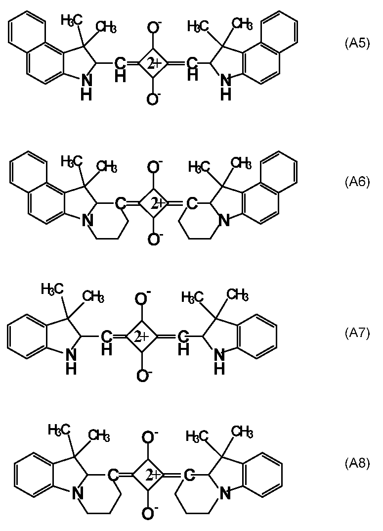
[NIR色素(A1-6)の製造]
以下、反応式(F1)を用いてNIR色素(A1-6)の製造例を具体的に説明する。なお、以下の説明において、原料成分((a)、(g))や中間生成物((b)~(h))におけるR1~R4について記載しないが、R1はイソプロピル基、R2はn-プロピル基、R3およびR4は水素原子である。
以下、反応式(F1)を用いてNIR色素(A1-6)の製造例を具体的に説明する。なお、以下の説明において、原料成分((a)、(g))や中間生成物((b)~(h))におけるR1~R4について記載しないが、R1はイソプロピル基、R2はn-プロピル基、R3およびR4は水素原子である。
NIR色素(A1-6)の製造は、反応式(F1)中の化合物(a)を東京化成工業(株)より入手し出発物質として用いた。
(化合物(b)の製造)
1Lナスフラスコに化合物(a)を31.50g(0.197mol)、ヨウ化イソプロピルを134.06g(0.79mol)加え、110℃で48時間反応させた。赤い沈殿物が析出し、反応容器中はヨウ化イソプロピルの液体が消失してほぼ固体になった。室温に戻して、ヘキサンを加え、沈殿物をろ過した。ろ過物をヘキサンで再び洗浄しろ過した。その結果、化合物(b)(63.9g、0.19mol、収率:98.0%)が得られた。
1Lナスフラスコに化合物(a)を31.50g(0.197mol)、ヨウ化イソプロピルを134.06g(0.79mol)加え、110℃で48時間反応させた。赤い沈殿物が析出し、反応容器中はヨウ化イソプロピルの液体が消失してほぼ固体になった。室温に戻して、ヘキサンを加え、沈殿物をろ過した。ろ過物をヘキサンで再び洗浄しろ過した。その結果、化合物(b)(63.9g、0.19mol、収率:98.0%)が得られた。
(化合物(c)の製造)
1Lナスフラスコに化合物(b)63.9g(0.19mol)、水200mlを加え、その後、水酸化ナトリウム水溶液(NaOH40g(1.0mol)+水200ml)を滴下した。添加後、室温で4時間反応させた後、ジクロロメタンと水で抽出し、ジクロロメタン層を、エバポレーターを用いて溶媒を除去した。濃縮した有機層をカラムクロマトグラフィー法にて精製した。その結果、液状の化合物(c)(33.6g、0.17mol、収率:86.7%)が得られた。
1Lナスフラスコに化合物(b)63.9g(0.19mol)、水200mlを加え、その後、水酸化ナトリウム水溶液(NaOH40g(1.0mol)+水200ml)を滴下した。添加後、室温で4時間反応させた後、ジクロロメタンと水で抽出し、ジクロロメタン層を、エバポレーターを用いて溶媒を除去した。濃縮した有機層をカラムクロマトグラフィー法にて精製した。その結果、液状の化合物(c)(33.6g、0.17mol、収率:86.7%)が得られた。
(化合物(d)の製造)
1Lのナスフラスコに化合物(c)33.6g(0.17mol)、メタノール700mlを加えた。0℃に冷却して水素化ホウ素ナトリウム(14.76g、0.39mol)を加えた。添加後、室温に戻し、4時間反応させた。反応終了後、水を加え、その後、酢酸エチルと水で抽出を行った、抽出後、得られた有機層を、エバポレーターを用いて溶媒を除去した。濃縮した有機層をカラムクロマトグラフィー法にて精製した。その結果、液状の化合物(d)(26.68g、0.13mol、収率:79.0%)が得られた。
1Lのナスフラスコに化合物(c)33.6g(0.17mol)、メタノール700mlを加えた。0℃に冷却して水素化ホウ素ナトリウム(14.76g、0.39mol)を加えた。添加後、室温に戻し、4時間反応させた。反応終了後、水を加え、その後、酢酸エチルと水で抽出を行った、抽出後、得られた有機層を、エバポレーターを用いて溶媒を除去した。濃縮した有機層をカラムクロマトグラフィー法にて精製した。その結果、液状の化合物(d)(26.68g、0.13mol、収率:79.0%)が得られた。
(化合物(e)の製造)
1Lのナスフラスコに化合物(d)26.68g(0.13mol)を加え、0℃の氷浴下で濃硫酸80g(0.81mol)を滴下した。濃硫酸滴下後、30分間攪拌した。その後、60%の濃硝酸19.19gと濃硫酸60gの混合溶液を氷浴下で滴下した。滴下終了後、反応温度を徐々に室温に戻し、同温度で15時間反応させた。反応終了後、再び0℃に冷却して、水300mlを加えた。さらに反応液が中性になるまで40質量%水酸化ナトリウム水溶液を滴下した。その後、ジクロロメタンで抽出した。得られた有機層を硫酸マグネシウムで乾燥し、エバポレーターを用いて溶媒を除去した。濃縮した有機層をカラムクロマトグラフィー法にて精製した。その結果、液状の化合物(e)(26.0g、0.10mol、収率:80.0%)が得られた。
1Lのナスフラスコに化合物(d)26.68g(0.13mol)を加え、0℃の氷浴下で濃硫酸80g(0.81mol)を滴下した。濃硫酸滴下後、30分間攪拌した。その後、60%の濃硝酸19.19gと濃硫酸60gの混合溶液を氷浴下で滴下した。滴下終了後、反応温度を徐々に室温に戻し、同温度で15時間反応させた。反応終了後、再び0℃に冷却して、水300mlを加えた。さらに反応液が中性になるまで40質量%水酸化ナトリウム水溶液を滴下した。その後、ジクロロメタンで抽出した。得られた有機層を硫酸マグネシウムで乾燥し、エバポレーターを用いて溶媒を除去した。濃縮した有機層をカラムクロマトグラフィー法にて精製した。その結果、液状の化合物(e)(26.0g、0.10mol、収率:80.0%)が得られた。
(化合物(f)の製造)
2Lのナスフラスコに、化合物(e)を26.0g(0.10mol)およびTHFを400ml投入し、次いで、氷浴下で、パラジウム炭素8gおよびエタノール400mlを順に加え、さらに、ギ酸アンモニウム93g(1.48mol)を添加した。その後、反応系を開放して大気雰囲気下室温で12時間撹拌した。反応終了後、水を加えた。反応液をろ過して、ろ液をジクロロメタン-水で分液した後、有機層を、エバポレーターを用いて濃縮した。濃縮した有機層をカラムクロマトグラフィーにて精製した。その結果、油状の化合物(f)(16.5g、0.075mol、収率:72.0%)が得られた。
2Lのナスフラスコに、化合物(e)を26.0g(0.10mol)およびTHFを400ml投入し、次いで、氷浴下で、パラジウム炭素8gおよびエタノール400mlを順に加え、さらに、ギ酸アンモニウム93g(1.48mol)を添加した。その後、反応系を開放して大気雰囲気下室温で12時間撹拌した。反応終了後、水を加えた。反応液をろ過して、ろ液をジクロロメタン-水で分液した後、有機層を、エバポレーターを用いて濃縮した。濃縮した有機層をカラムクロマトグラフィーにて精製した。その結果、油状の化合物(f)(16.5g、0.075mol、収率:72.0%)が得られた。
(化合物(h)の製造)
2Lのナスフラスコに、化合物(f)4.0g(0.018mol)、ジクロロメタン90mlおよびジイソプロピルエチルアミン2.84g(0.022mol)を加え、次いで、置換基R2を有するクロロギ酸エステル2.68g(0.022mol)を滴下した。滴下終了後、室温に戻して2時間反応させた。反応終了後、水を加え、ジクロロメタンで抽出を行った。得られた有機層を硫酸ナトリウムで乾燥し、エバポレーターを用いて溶媒を除去した後、濃縮した有機層をカラムクロマトグラフィー法にて精製した。その結果、固体の化合物(h)(3.2g、0.011mol、収率:57%)が得られた。
2Lのナスフラスコに、化合物(f)4.0g(0.018mol)、ジクロロメタン90mlおよびジイソプロピルエチルアミン2.84g(0.022mol)を加え、次いで、置換基R2を有するクロロギ酸エステル2.68g(0.022mol)を滴下した。滴下終了後、室温に戻して2時間反応させた。反応終了後、水を加え、ジクロロメタンで抽出を行った。得られた有機層を硫酸ナトリウムで乾燥し、エバポレーターを用いて溶媒を除去した後、濃縮した有機層をカラムクロマトグラフィー法にて精製した。その結果、固体の化合物(h)(3.2g、0.011mol、収率:57%)が得られた。
(NIR色素(A1-6)の製造)
1LのナスフラスコにDean-Stark管を取り付け、化合物(h)2.5g(0.008mol)、スクアリン酸0.47g(0.0041mol)、オルトギ酸エチル4.68g(0.032mol)、エタノール100mlを加え、90℃で8時間加熱撹拌した。反応終了後、エバポレーターを用いて溶媒を除去した後、カラムクロマトグラフィー法にて精製した。その結果、NIR色素(A1-6)(2.3g、0.0033mol、収率:81%)が得られた。
1LのナスフラスコにDean-Stark管を取り付け、化合物(h)2.5g(0.008mol)、スクアリン酸0.47g(0.0041mol)、オルトギ酸エチル4.68g(0.032mol)、エタノール100mlを加え、90℃で8時間加熱撹拌した。反応終了後、エバポレーターを用いて溶媒を除去した後、カラムクロマトグラフィー法にて精製した。その結果、NIR色素(A1-6)(2.3g、0.0033mol、収率:81%)が得られた。
[NIR色素(A1-1)、(A1-3)~(A1-5)の製造]
NIR色素(A1-6)の製造において、ヨウ化イソプロピルに代えてヨードメタンを用い、かつ置換基R2を有するクロロギ酸エステル(g)のR2を、それぞれ表1に示すR2とした以外は同様にして、NIR色素(A1-1)、(A1-3)~(A1-5)を製造した。
NIR色素(A1-6)の製造において、ヨウ化イソプロピルに代えてヨードメタンを用い、かつ置換基R2を有するクロロギ酸エステル(g)のR2を、それぞれ表1に示すR2とした以外は同様にして、NIR色素(A1-1)、(A1-3)~(A1-5)を製造した。
[NIR色素(A1-2)の製造]
NIR色素(A1-6)の製造において、ヨウ化イソプロピルに代えてヨードメタンを用いた以外は同様にして、NIR色素(A1-2)を製造した。
NIR色素(A1-6)の製造において、ヨウ化イソプロピルに代えてヨードメタンを用いた以外は同様にして、NIR色素(A1-2)を製造した。
[NIR色素(A1-7)~(A1-9)の製造]
NIR色素(A1-6)の製造において、置換基R2を有するクロロギ酸エステル(g)のR2を、それぞれ表1に示すR2とした以外は同様にして、NIR色素(A1-7)~(A1-9)を製造した。
NIR色素(A1-6)の製造において、置換基R2を有するクロロギ酸エステル(g)のR2を、それぞれ表1に示すR2とした以外は同様にして、NIR色素(A1-7)~(A1-9)を製造した。
[NIR色素(A1-12)の製造]
NIR色素(A1-12)の製造では、反応式(F1)中の化合物(a)(ただし、R3、R4は水素原子)を出発原料とした。そして、反応式(F2-1)に示す経路を経て、反応式(F1)中の化合物(f)(ただし、R1は1,1-ジメチルプロピル基、R3、R4は水素原子)を製造し、この化合物(f)から、NIR色素(A1-6)の場合と同様にして、化合物(h)(ただし、R1は-(CH3)2CC2H5、R2は-CH2CH2CH3(n-C3H7)、R3、R4は水素原子)を経てNIR色素(A1-10)を製造した。なお、反応式(F2-1)中、TSOHはp-トルエンスルホン酸を示す。以下、本明細書中、TSOHは前記と同じ意味で用いられる。
NIR色素(A1-12)の製造では、反応式(F1)中の化合物(a)(ただし、R3、R4は水素原子)を出発原料とした。そして、反応式(F2-1)に示す経路を経て、反応式(F1)中の化合物(f)(ただし、R1は1,1-ジメチルプロピル基、R3、R4は水素原子)を製造し、この化合物(f)から、NIR色素(A1-6)の場合と同様にして、化合物(h)(ただし、R1は-(CH3)2CC2H5、R2は-CH2CH2CH3(n-C3H7)、R3、R4は水素原子)を経てNIR色素(A1-10)を製造した。なお、反応式(F2-1)中、TSOHはp-トルエンスルホン酸を示す。以下、本明細書中、TSOHは前記と同じ意味で用いられる。
(化合物(i)の製造)
1Lのナスフラスコに化合物(a)を50.0g(0.31mol)、p-トルエンスルホン酸を60.0g(0.35mol)を加え、次いで、水素化ホウ素ナトリウムを114.0g(0.37mol)0℃で加えた。メカニカルスターラーで撹拌しながら2時間反応させた後、再度0℃に冷却し、水を滴下して反応を終了させた。反応終了後、ジクロロメタンと水で抽出し、ジクロロメタン層を、エバポレーターを用いて溶媒を除去した後、濃縮した有機層をカラムクロマトグラフィー法にて精製した。その結果、固体の化合物(i)(46.0g、0.29mol、収率:91.0%)が得られた。
1Lのナスフラスコに化合物(a)を50.0g(0.31mol)、p-トルエンスルホン酸を60.0g(0.35mol)を加え、次いで、水素化ホウ素ナトリウムを114.0g(0.37mol)0℃で加えた。メカニカルスターラーで撹拌しながら2時間反応させた後、再度0℃に冷却し、水を滴下して反応を終了させた。反応終了後、ジクロロメタンと水で抽出し、ジクロロメタン層を、エバポレーターを用いて溶媒を除去した後、濃縮した有機層をカラムクロマトグラフィー法にて精製した。その結果、固体の化合物(i)(46.0g、0.29mol、収率:91.0%)が得られた。
(化合物(k)の製造)
1Lのナスフラスコに化合物(i)を45.7g(0.28mol)、ジイソプロピルエチルアミンを54.9g(0.43mol)、化合物(j)を40.0g(0.29mol)、ヨウ化銅を5.0g(0.026mol)、THFを600ml加えた。50℃で13時間反応させ、さらにヨウ化銅を5.0g(0.026mol)追加して、5時間反応させた。反応終了後、ジクロロメタンと水で抽出し、ジクロロメタン層を、エバポレーターを用いて溶媒を除去した後、濃縮した有機層をカラムクロマトグラフィー法にて精製した。その結果、化合物(k)(31.0g、0.13mol、収率:45.0%)が得られた。
なお、化合物(j)は、化合物(l)から、反応式(F2-2)に示す反応経路を経て生成したものである。すなわち、1Lのナスフラスコに化合物(l)を75.0g(0.76mol)、無水酢酸を90.0g(0.88mol)、トリエチルアミンを100.0g(0.99mol)、ジクロロメタンを1L加え、40℃で24時間反応させた。反応終了後、炭酸水素ナトリウム水溶液と水で分液し、エバポレーターを用いて溶媒を除去した後、蒸留により精製した。その結果、固体の化合物(i)(46.0g、0.29mol、収率:91.0%)が得られた。
1Lのナスフラスコに化合物(i)を45.7g(0.28mol)、ジイソプロピルエチルアミンを54.9g(0.43mol)、化合物(j)を40.0g(0.29mol)、ヨウ化銅を5.0g(0.026mol)、THFを600ml加えた。50℃で13時間反応させ、さらにヨウ化銅を5.0g(0.026mol)追加して、5時間反応させた。反応終了後、ジクロロメタンと水で抽出し、ジクロロメタン層を、エバポレーターを用いて溶媒を除去した後、濃縮した有機層をカラムクロマトグラフィー法にて精製した。その結果、化合物(k)(31.0g、0.13mol、収率:45.0%)が得られた。
なお、化合物(j)は、化合物(l)から、反応式(F2-2)に示す反応経路を経て生成したものである。すなわち、1Lのナスフラスコに化合物(l)を75.0g(0.76mol)、無水酢酸を90.0g(0.88mol)、トリエチルアミンを100.0g(0.99mol)、ジクロロメタンを1L加え、40℃で24時間反応させた。反応終了後、炭酸水素ナトリウム水溶液と水で分液し、エバポレーターを用いて溶媒を除去した後、蒸留により精製した。その結果、固体の化合物(i)(46.0g、0.29mol、収率:91.0%)が得られた。
(化合物(f)の製造)
1Lのナスフラスコに、化合物(k)を30.0g(0.12mol)、パラジウム炭素を5gおよびTHFを500ml投入し、常圧で水素を添加して8時間反応させた。反応終了後、反応液をろ過してパラジウム炭素を取り除き、さらに、エバポレーターを用いて溶媒を除去し、残渣をカラムクロマトグラフィーにて精製した。その結果、化合物(f)(25.0g、0.10mol、収率:82.0%)が得られた。
1Lのナスフラスコに、化合物(k)を30.0g(0.12mol)、パラジウム炭素を5gおよびTHFを500ml投入し、常圧で水素を添加して8時間反応させた。反応終了後、反応液をろ過してパラジウム炭素を取り除き、さらに、エバポレーターを用いて溶媒を除去し、残渣をカラムクロマトグラフィーにて精製した。その結果、化合物(f)(25.0g、0.10mol、収率:82.0%)が得られた。
(NIR色素(A1-12)の製造)
このようにして得られた化合物(f)を用い、置換基R2を有するクロロギ酸エステル(g)のR2を、表1に示すR2とした以外はNIR色素(A1-6)の場合と同様にして、NIR色素(A1-12)を製造した。
このようにして得られた化合物(f)を用い、置換基R2を有するクロロギ酸エステル(g)のR2を、表1に示すR2とした以外はNIR色素(A1-6)の場合と同様にして、NIR色素(A1-12)を製造した。
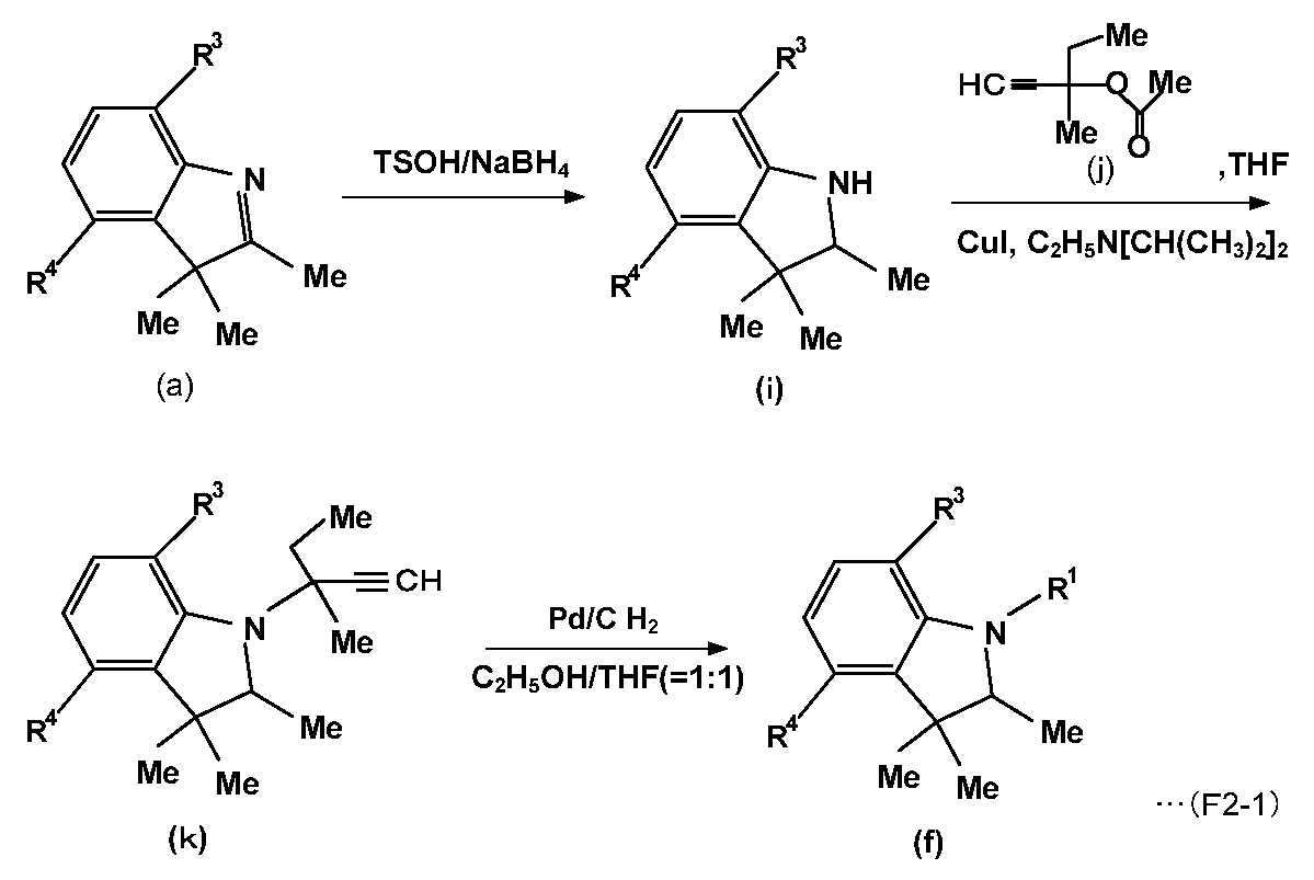

[NIR色素(A1-13)の製造]
NIR色素(A1-12)の製造において、置換基R2を有するクロロギ酸エステル(g)のR2を表1に示すR2とした以外は同様にして、NIR色素(A1-13)を製造した。
NIR色素(A1-12)の製造において、置換基R2を有するクロロギ酸エステル(g)のR2を表1に示すR2とした以外は同様にして、NIR色素(A1-13)を製造した。
[NIR色素(A1-10)の製造]
NIR色素(A1-12)の製造において、化合物(j)に代えて、下記に示す化合物(j’)を用いた以外は同様にして、色素(A1-10)を製造した。
なお、化合物(j’)は、化合物(j)の製造において、出発物質として化合物(l)に代えて、化合物(l’)を用いた以外は同様にして製造したものである。
NIR色素(A1-12)の製造において、化合物(j)に代えて、下記に示す化合物(j’)を用いた以外は同様にして、色素(A1-10)を製造した。
なお、化合物(j’)は、化合物(j)の製造において、出発物質として化合物(l)に代えて、化合物(l’)を用いた以外は同様にして製造したものである。
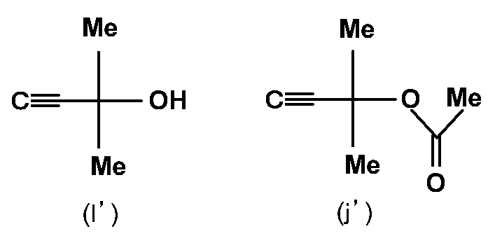
[NIR色素(A1-11)の製造]
NIR色素(A1-10)の製造において、置換基R2を有するクロロギ酸エステル(g)のR2を表1に示すR2とした以外は同様にして、NIR色素(A1-11)を製造した。
NIR色素(A1-10)の製造において、置換基R2を有するクロロギ酸エステル(g)のR2を表1に示すR2とした以外は同様にして、NIR色素(A1-11)を製造した。
なお、比較用NIR色素(A2)~(A8)については、NIR色素(A2)~(A4)は、国際公開第14/088063号明細書に記載された方法により製造し、NIR色素(A5)~(A8)は、国際公開第11/086785号明細書に記載された方法により製造した。
<NIR色素の評価>
(1)ジクロロメタン中におけるNIR色素の吸収特性
得られたNIR色素をジクロロメタン中に溶解し、紫外可視分光光度計((株)日立ハイテクノロジーズ社製、U-4100形)を用いて分光透過率曲線を測定し、最大吸収波長λmax、最大吸収波長における透過率を10%としたときの前記最大吸収波長より短波長側で透過率が80%となる波長λ80、最大吸収波長λmaxと波長λ80との差(λmax-λ80)、波長430~550nmの光における最大吸光係数εA、波長670~730nmの光における最大吸光係数εB、およびそれらの比(εB/εA)を算出した。結果を表3に示す。なお、以降の例における分光透過率曲線の測定には、いずれもU-4100形を用いた。
(1)ジクロロメタン中におけるNIR色素の吸収特性
得られたNIR色素をジクロロメタン中に溶解し、紫外可視分光光度計((株)日立ハイテクノロジーズ社製、U-4100形)を用いて分光透過率曲線を測定し、最大吸収波長λmax、最大吸収波長における透過率を10%としたときの前記最大吸収波長より短波長側で透過率が80%となる波長λ80、最大吸収波長λmaxと波長λ80との差(λmax-λ80)、波長430~550nmの光における最大吸光係数εA、波長670~730nmの光における最大吸光係数εB、およびそれらの比(εB/εA)を算出した。結果を表3に示す。なお、以降の例における分光透過率曲線の測定には、いずれもU-4100形を用いた。

表3に示すとおり、NIR色素(A1-1)~(A1-13)はいずれも(i-1)~(i-3)を満たしている。一方、NIR色素(A2)~(A4)は(i-2)を満たさず、NIR色素(A5)は(i-3)を満たさない。また、NIR色素(A7)は(i-1)および(i-2)を満たさず、また、NIR色素(A8)は(i-3)を満たさず、NIR色素(A6)は(i-2)および(i-3)を満たさない。
(2)透明樹脂中におけるNIR色素の吸収特性
(例1-1~例1-12)
得られたNIR色素のうち表4に示すNIR色素をそれぞれポリイミド樹脂(ネオプリム(登録商標)C3450)のシクロヘキサノン溶液と混合し、室温にて撹拌・溶解することで塗工液を得た。なお、例1-11では、用いたNIR色素(A2)が樹脂溶液に溶解せず、塗工液を調製できなかった。
得られた塗工液を、厚さ0.3mmのガラス(無アルカリガラス;旭硝子(株)製、商品名:AN100)基板上にスピンコート法により塗布し、加熱乾燥させ、厚さ0.9μm~1.1μmの吸収層を形成し、透明基板と吸収層からなるNIRフィルタ(例1-1~例1-10、例1-12)を得た。
(例1-1~例1-12)
得られたNIR色素のうち表4に示すNIR色素をそれぞれポリイミド樹脂(ネオプリム(登録商標)C3450)のシクロヘキサノン溶液と混合し、室温にて撹拌・溶解することで塗工液を得た。なお、例1-11では、用いたNIR色素(A2)が樹脂溶液に溶解せず、塗工液を調製できなかった。
得られた塗工液を、厚さ0.3mmのガラス(無アルカリガラス;旭硝子(株)製、商品名:AN100)基板上にスピンコート法により塗布し、加熱乾燥させ、厚さ0.9μm~1.1μmの吸収層を形成し、透明基板と吸収層からなるNIRフィルタ(例1-1~例1-10、例1-12)を得た。
(例2-1~例2-7)
得られたNIR色素のうち表5に示す色素をそれぞれ、ポリイミド樹脂(C3630)を混合溶媒(シクロヘキサノン+NMP)に溶解して調製したシクロヘキサノン溶液とNMP溶液と混合し、室温にて撹拌・溶解することで塗工液を得た。なお、例2-6では、用いたNIR色素(A2)が樹脂溶液に溶解せず、塗工液を調製できなかった。
得られた塗工液を、厚さ0.3mmのガラス(AN100)基板上にスピンコート法により塗布し、加熱乾燥させ、厚さ0.9~1.2μmの吸収層を形成し、NIRフィルタ(例2-1~例2-5、例2-7)を得た。
得られたNIR色素のうち表5に示す色素をそれぞれ、ポリイミド樹脂(C3630)を混合溶媒(シクロヘキサノン+NMP)に溶解して調製したシクロヘキサノン溶液とNMP溶液と混合し、室温にて撹拌・溶解することで塗工液を得た。なお、例2-6では、用いたNIR色素(A2)が樹脂溶液に溶解せず、塗工液を調製できなかった。
得られた塗工液を、厚さ0.3mmのガラス(AN100)基板上にスピンコート法により塗布し、加熱乾燥させ、厚さ0.9~1.2μmの吸収層を形成し、NIRフィルタ(例2-1~例2-5、例2-7)を得た。
(例3-1~例3-9)
得られた色素のうち表6に示すNIR色素をそれぞれポリエーテルスルホン樹脂(スミカエクセル(登録商標)PES4800)のシクロヘキサノン溶液と混合し、室温にて撹拌・溶解することで塗工液を得た。なお、例3-9では、用いたNIR色素(A2)が樹脂溶液に溶解せず、塗工液を調製できなかった。
得られた塗工液を、厚さ0.3mmのガラス(AN100)基板上にスピンコート法により塗布し、加熱乾燥させ、厚さ0.9~1.0μmの吸収層を形成し、NIRフィルタ(例3-1~例3-8)を得た。
(例4-1~例4-11)
得られたNIR色素のうち表7に示す色素をそれぞれポリエステル樹脂(OKP850)のシクロヘキサノン溶液と混合し、室温にて撹拌・溶解することで塗工液を得た。なお、例4-11では、用いたNIR色素(A2)が樹脂溶液に溶解せず、塗工液を調製できなかった。
得られた塗工液を、厚さ0.3mmのガラス(AN100)基板上にスピンコート法により塗布し、加熱乾燥させ、厚さ0.9~1.0μmの吸収層を形成し、NIRフィルタ(例4-1~例4-10)を得た。
得られた色素のうち表6に示すNIR色素をそれぞれポリエーテルスルホン樹脂(スミカエクセル(登録商標)PES4800)のシクロヘキサノン溶液と混合し、室温にて撹拌・溶解することで塗工液を得た。なお、例3-9では、用いたNIR色素(A2)が樹脂溶液に溶解せず、塗工液を調製できなかった。
得られた塗工液を、厚さ0.3mmのガラス(AN100)基板上にスピンコート法により塗布し、加熱乾燥させ、厚さ0.9~1.0μmの吸収層を形成し、NIRフィルタ(例3-1~例3-8)を得た。
(例4-1~例4-11)
得られたNIR色素のうち表7に示す色素をそれぞれポリエステル樹脂(OKP850)のシクロヘキサノン溶液と混合し、室温にて撹拌・溶解することで塗工液を得た。なお、例4-11では、用いたNIR色素(A2)が樹脂溶液に溶解せず、塗工液を調製できなかった。
得られた塗工液を、厚さ0.3mmのガラス(AN100)基板上にスピンコート法により塗布し、加熱乾燥させ、厚さ0.9~1.0μmの吸収層を形成し、NIRフィルタ(例4-1~例4-10)を得た。
作製したNIRフィルタについて、分光透過率曲線を測定した。その測定結果から、吸収層の、最大吸収波長λPmax、波長430~550nmの光の最小透過率、波長430~480nmの光の平均透過率、波長690~730nmの光の透過率が1%以下となる吸収幅(透過率が1%以下となる最も長い波長λbと透過率が1%以下となる最も短い波長λaとの差(λb-λa);吸収幅と表記)、最大吸収波長λPmaxにおける透過率を10%としたときの前記最大吸収波長より短波長側で透過率が80%となる波長λP80、最大吸収波長λPmaxと波長λP80との差(λPmax-λP80)を算出した。結果を、吸収層の膜厚、および吸収層におけるNIR色素の樹脂に対する割合とともに、表4~7に併せ示す。
なお、表4~7に示した値は、NIRフィルタの分光透過率曲線から、ガラス基板の透過率等を減算した値である。具体的にはガラス基板の吸収、ガラス基板と吸収層界面、ガラス基板と空気界面の反射の影響を差し引いて、吸収層と空気界面での反射を計算した値となっている。
なお、表4~7に示した値は、NIRフィルタの分光透過率曲線から、ガラス基板の透過率等を減算した値である。具体的にはガラス基板の吸収、ガラス基板と吸収層界面、ガラス基板と空気界面の反射の影響を差し引いて、吸収層と空気界面での反射を計算した値となっている。
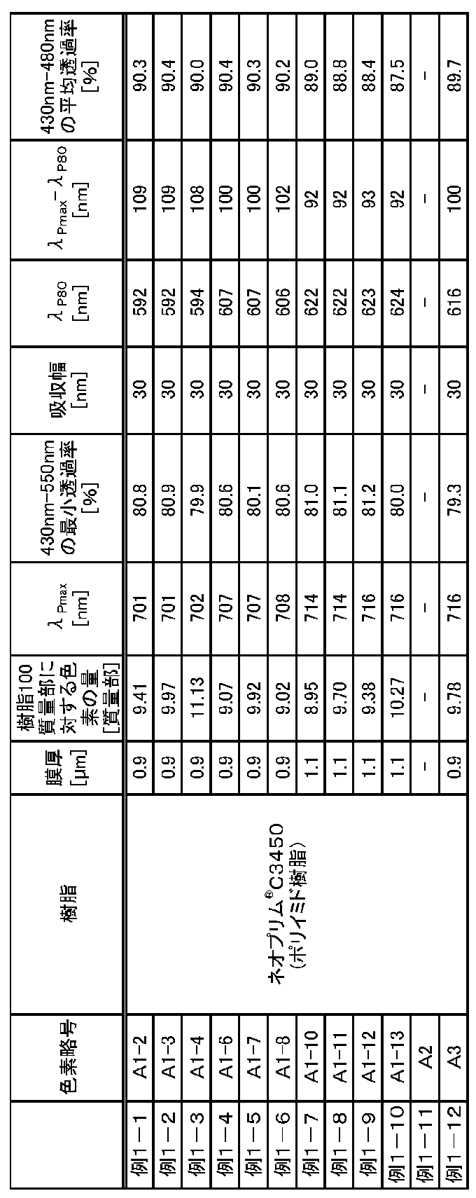
表4に示されるように、ポリイミド樹脂(C3450)を用いた例において、例1-1~例1-10は、最大吸収波長λPmaxが波長701~716nmにあり、波長430~480nmの光の平均透過率が87%以上、λPmax-λP80が109nm以下であった。これは、式(AI)で示されるスクアリリウム系色素を含む例は、波長600~700nmの光の透過率を高く保持でき、また、波長430~480nmの可視域の光の透過率が高く、かつ可視域と近赤外域の境界付近における吸収曲線が急峻であることを示している。
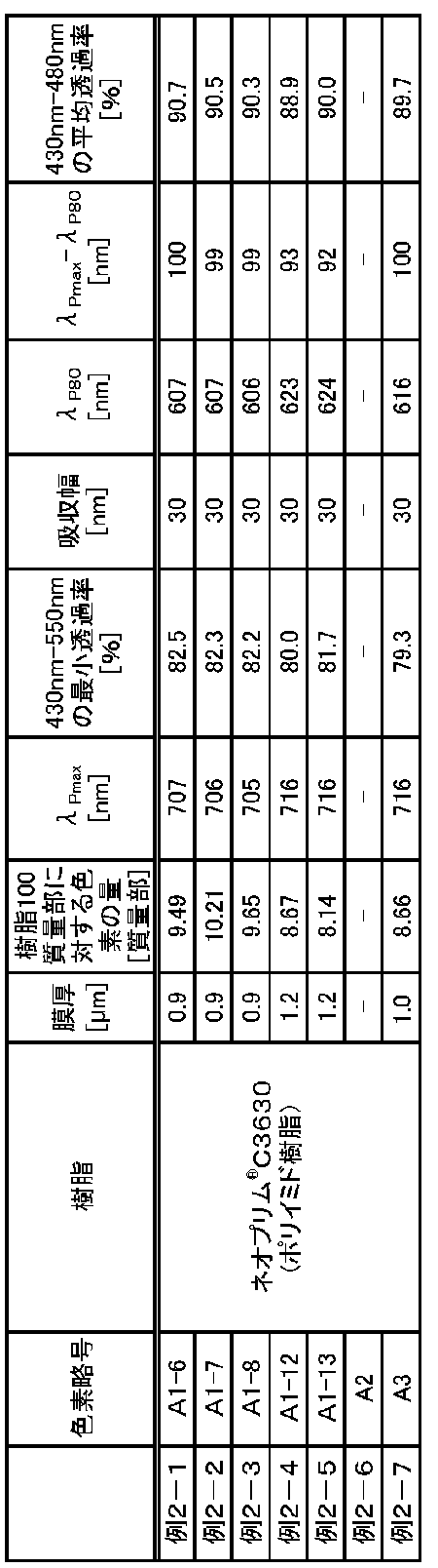
表5に示されるように、ポリイミド樹脂(C3630)を用いた例において、例2-1~例2-5は、最大吸収波長λPmaxが波長705~716nmにあり、波長430~480nmの光の平均透過率が87%以上、λPmax-λP80が100nm以下であった。これは、式(AI)で示されるスクアリリウム系色素を含む例は、波長600~700nmの光の透過率を高く保持でき、また、波長430~480nmの可視域の光の透過率が高く、かつ可視域と近赤外域の境界付近における吸収曲線が急峻であることを示している。
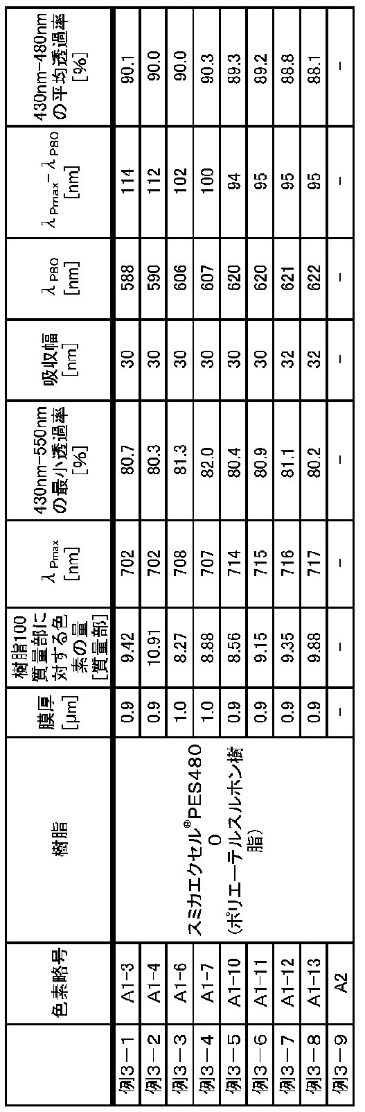
表6に示されるように、ポリエーテルスルホン樹脂(スミカエクセル(登録商標)PES4800)を用いた例において、例3-1~例3-8は、最大吸収波長λPmaxが波長702~717nmにあり、波長430~480nmの光の平均透過率が87%以上、λPmax-λP80が114nm以下であった。これは、式(AI)で示されるスクアリリウム系色素を含む例は、波長600~700nmの光の透過率を高く保持でき、また、波長430~480nmの可視域の透過率が高く、かつ可視域と近赤外域の境界付近における吸収曲線が急峻であることを示している。
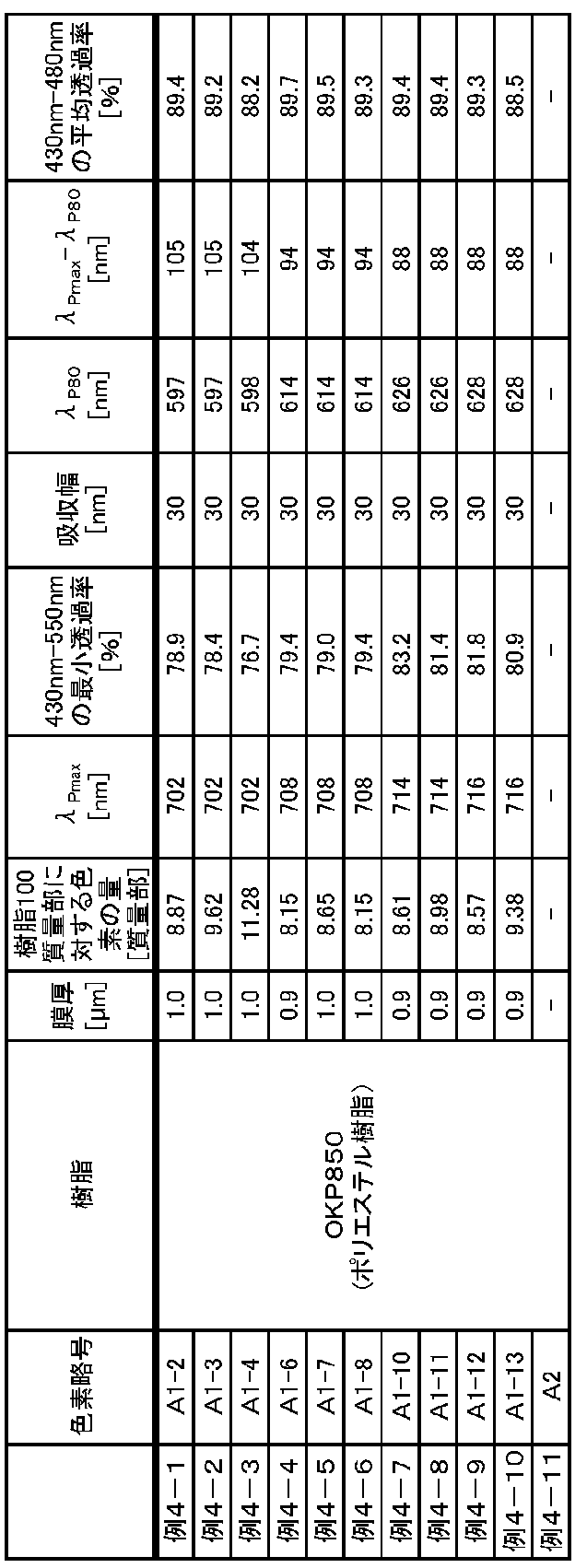
表7に示されるように、ポリエステル樹脂(OKP850)を用いた例において、例4-1~例4-10は、最大吸収波長λPmaxが波長702~716nmにあり、波長430~480nmの光の平均透過率が87%以上、λPmax-λP80が105nm以下であった。これは、式(AI)で示されるスクアリリウム系色素を含む例は、波長600~700nmの光の透過率を高く保持でき、また、波長430~480nmの可視域の光の透過率が高く、かつ可視域と近赤外域の境界付近における吸収曲線が急峻であることを示している。
(3)NIR色素の溶解性
得られたNIR色素のうち実施例用色素について、樹脂溶液に対する溶解性を評価した。
溶解性試験では樹脂溶液として、ポリイミド樹脂(C3450)、ポリエーテルスルホン樹脂(スミカエクセル(登録商標)PES4800)およびポリエステル樹脂(OKP850)をそれぞれ混合溶媒(シクロヘキサノン:NMP=1:1)に溶解して調製した樹脂濃度12.5質量%の3種の溶液を用いた。結果を、用いた色素の種類とともに表8に示す。なお、溶解性試験における樹脂溶液の温度は50℃とし、その中にNIR色素を投入し、2時間攪拌して、溶解の有無を目視にて観察した。溶解性の評価基準は下記のとおりである。
A:溶解度9質量%以上
B:溶解度7質量%以上9質量%未満
C:溶解度5質量%以上7質量%未満
D:溶解度3質量%以上5質量%未満
E:溶解度1質量%以上3質量%未満
F:溶解度1質量%未満
得られたNIR色素のうち実施例用色素について、樹脂溶液に対する溶解性を評価した。
溶解性試験では樹脂溶液として、ポリイミド樹脂(C3450)、ポリエーテルスルホン樹脂(スミカエクセル(登録商標)PES4800)およびポリエステル樹脂(OKP850)をそれぞれ混合溶媒(シクロヘキサノン:NMP=1:1)に溶解して調製した樹脂濃度12.5質量%の3種の溶液を用いた。結果を、用いた色素の種類とともに表8に示す。なお、溶解性試験における樹脂溶液の温度は50℃とし、その中にNIR色素を投入し、2時間攪拌して、溶解の有無を目視にて観察した。溶解性の評価基準は下記のとおりである。
A:溶解度9質量%以上
B:溶解度7質量%以上9質量%未満
C:溶解度5質量%以上7質量%未満
D:溶解度3質量%以上5質量%未満
E:溶解度1質量%以上3質量%未満
F:溶解度1質量%未満
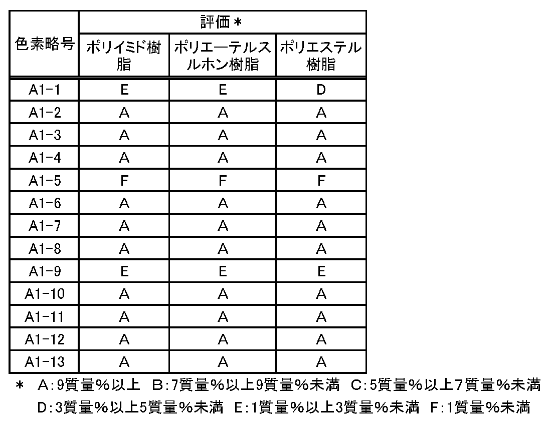
表8に示すとおり、置換基R2が炭素原子数3個以上のアルキル構造を有する色素(A1-2)~(A1-4)、(A1-6)~(A1-8)および(A1-10)~(A1-13)は、メチル基(炭素原子数1個)やフェニル基を有する他の色素に比べ、樹脂溶液に対し高い溶解性を有している。このことから、置換基R1炭素原子数3個以上のアルキル構造が溶解性の向上に寄与する一方、環構造が溶解性を低下させていると推定される。樹脂溶液に対する溶液性が高いと、塗工性が向上し、厚さの薄い樹脂膜を形成し得る。また、薄い樹脂膜とすることで、熱処理時の樹脂の膨張を抑制でき、光学フィルタを構成する他の部材、他の機能層への悪影響を低減できる。具体的には、例えば、反射防止層の破損等を抑制できる。
<光学フィルタ[I]の製造>
(例5-1)
ポリイミド樹脂(C3450)を混合溶媒(シクロヘキサノン+NMP)に溶解して調製した溶液に、上記NIR吸収色素(A1-2)をポリイミド樹脂の質量に対して11質量%となる割合で添加し溶解させて、吸収層を形成するための塗工液を調製した。
この塗工液を、厚さ0.3mmのガラス(AN100)基板上にスピンコート法により塗布し、大気圧下、加熱して、厚さ約1.0μmの吸収層を形成した。
この後、吸収層の表面に、蒸着法により、TiO2膜とSiO2膜を交互に積層して反射防止層を形成し、光学フィルタを得た。
(例5-1)
ポリイミド樹脂(C3450)を混合溶媒(シクロヘキサノン+NMP)に溶解して調製した溶液に、上記NIR吸収色素(A1-2)をポリイミド樹脂の質量に対して11質量%となる割合で添加し溶解させて、吸収層を形成するための塗工液を調製した。
この塗工液を、厚さ0.3mmのガラス(AN100)基板上にスピンコート法により塗布し、大気圧下、加熱して、厚さ約1.0μmの吸収層を形成した。
この後、吸収層の表面に、蒸着法により、TiO2膜とSiO2膜を交互に積層して反射防止層を形成し、光学フィルタを得た。
(例5-2~例5-10)
例5-2~例5-10は、吸収層を形成するための塗工液に添加するNIR吸収色素類および/または樹脂の種類を表9に示すように変えた以外は、例5-1と同様にして光学フィルタを製造した。
例5-2~例5-10は、吸収層を形成するための塗工液に添加するNIR吸収色素類および/または樹脂の種類を表9に示すように変えた以外は、例5-1と同様にして光学フィルタを製造した。
<光学フィルタ[I]の密着性の評価>
作製した光学フィルタについて、(1)~(3)の条件で、100マス(10mm×10mm)碁盤目テープ剥離試験を行い、100マス中、剥離が生じたマスの数を計数し、密着性を評価した(例5-6~例5-10については、(1)および(2)の条件でのみ実施)。
条件(1):3.9N/cmのテープで剥離
条件(2):6.0N/cmのテープで剥離
条件(3):光学フィルタを30℃の水に10分間浸漬後、6.0N/cmのテープで剥離
結果を、表9に併せ示す。密着性の評価基準は下記のとおりである。
A:0個(剥がれなし)
B:1~9個
C:10~30個
D:31~50個
E:51~100個
作製した光学フィルタについて、(1)~(3)の条件で、100マス(10mm×10mm)碁盤目テープ剥離試験を行い、100マス中、剥離が生じたマスの数を計数し、密着性を評価した(例5-6~例5-10については、(1)および(2)の条件でのみ実施)。
条件(1):3.9N/cmのテープで剥離
条件(2):6.0N/cmのテープで剥離
条件(3):光学フィルタを30℃の水に10分間浸漬後、6.0N/cmのテープで剥離
結果を、表9に併せ示す。密着性の評価基準は下記のとおりである。
A:0個(剥がれなし)
B:1~9個
C:10~30個
D:31~50個
E:51~100個
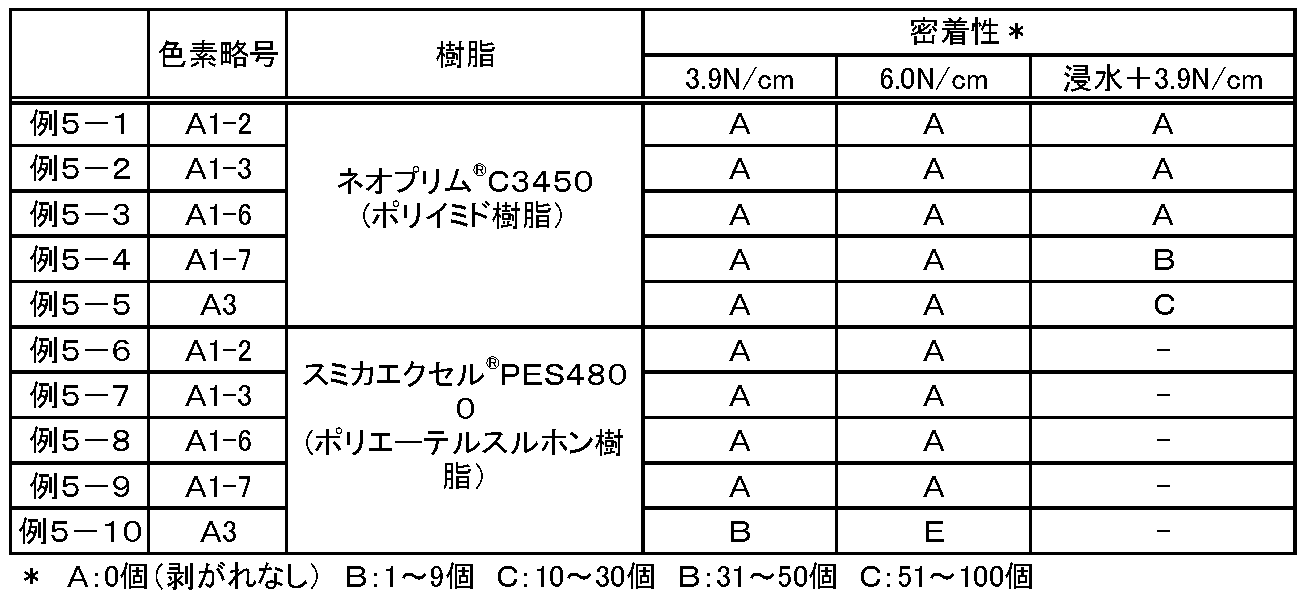
表9から明らかなように、式(AI)で示されるスクアリリウム系色素を含む例5-1~例5-4、例5-6~例5-9の光学フィルタは、ガラスや誘電体多層膜に対し密着性が低い樹脂として知られるポリイミド樹脂やポリエーテルスルホン樹脂が用いられた場合でも良好な密着性を示した。
<光学フィルタ[II]の製造>
(例6-1)
厚さ0.3mmのガラス(AN100)基板に蒸着法により、TiO2膜とSiO2膜を交互に積層して、誘電体多層膜52層からなる選択波長遮蔽層を形成した。選択波長遮蔽層の構成は、誘電体多層膜の積層数、TiO2膜の膜厚およびSiO2膜の膜厚をパラメータとしてシミュレーションし、入射角0°および30°の各分光透過率曲線において、(iii-1)および(iii-2)を満たすように、具体的には、本例では、波長420~695nmの光の透過率が90%以上、波長704nm(後述する吸収層の波長650~800nmの光における透過率が1%となる最大波長)~1100nmの光における透過率が1%以下となるように求めたものである。図2に、上記設計をもとに作製した選択波長遮蔽層の分光透過率曲線(入射角0°および30°)を示す。
(例6-1)
厚さ0.3mmのガラス(AN100)基板に蒸着法により、TiO2膜とSiO2膜を交互に積層して、誘電体多層膜52層からなる選択波長遮蔽層を形成した。選択波長遮蔽層の構成は、誘電体多層膜の積層数、TiO2膜の膜厚およびSiO2膜の膜厚をパラメータとしてシミュレーションし、入射角0°および30°の各分光透過率曲線において、(iii-1)および(iii-2)を満たすように、具体的には、本例では、波長420~695nmの光の透過率が90%以上、波長704nm(後述する吸収層の波長650~800nmの光における透過率が1%となる最大波長)~1100nmの光における透過率が1%以下となるように求めたものである。図2に、上記設計をもとに作製した選択波長遮蔽層の分光透過率曲線(入射角0°および30°)を示す。
また、ポリイミド樹脂(C3450)を混合溶媒(シクロヘキサノン+NMP)に溶解して調製した溶液に、シランカップリング剤としてN-[2-[3-(トリメトキシシリル)プロピル]アミノ]エチル]ウレアをポリイミド樹脂の質量に対して3質量%となる割合で添加し溶解させた。さらに、この樹脂溶液に、得られたNIR色素(A1-6)、およびUV色素(M-2)を、ポリイミド樹脂の質量に対してそれぞれ10.9質量%および4.5質量%となる割合で添加し溶解させて、吸収層を形成するための塗工液を調製した。
この塗工液を、選択波長遮蔽層を形成した上記ガラス基板の選択波長遮蔽層形成面とは反対側の面に、スピンコート法により塗布し、大気圧下、加熱して、厚さ約1.0μmの吸収層を形成した。
この後、吸収層の表面に、選択波長遮蔽層と同様、蒸着法により、TiO2膜とSiO2膜を交互に積層して反射防止層を形成し、光学フィルタを得た。
なお、反射防止層の構成もまた、誘電体多層膜の積層数、TiO2膜の膜厚およびSiO2膜の膜厚をパラメータとして、所望の光学特性を有するようにシミュレーションして決定した。
この後、吸収層の表面に、選択波長遮蔽層と同様、蒸着法により、TiO2膜とSiO2膜を交互に積層して反射防止層を形成し、光学フィルタを得た。
なお、反射防止層の構成もまた、誘電体多層膜の積層数、TiO2膜の膜厚およびSiO2膜の膜厚をパラメータとして、所望の光学特性を有するようにシミュレーションして決定した。
(例6-2)
ポリイミド樹脂(C3450)に代えて、ポリイミド樹脂(C3630)を用いるとともに、該ポリイミド樹脂の質量に対してNIR色素(A1-6)を12.8%となる割合で添加した以外は、例6-1と同様にして、光学フィルタを製造した。
ポリイミド樹脂(C3450)に代えて、ポリイミド樹脂(C3630)を用いるとともに、該ポリイミド樹脂の質量に対してNIR色素(A1-6)を12.8%となる割合で添加した以外は、例6-1と同様にして、光学フィルタを製造した。
(例6-3)
NIR吸収色素(A1-6)に代えてNIR色素(A3)を用いるとともに、該NIR色素(A3)をポリイミド樹脂の質量に対して10.1%となる割合で添加した以外は、例6-1と同様にして、光学フィルタを製造した。
NIR吸収色素(A1-6)に代えてNIR色素(A3)を用いるとともに、該NIR色素(A3)をポリイミド樹脂の質量に対して10.1%となる割合で添加した以外は、例6-1と同様にして、光学フィルタを製造した。
(例6-4)
ポリイミド樹脂(C3450)に代えて、ポリイミド樹脂(C3630)を用いるとともに、該ポリイミド樹脂の質量に対してNIR色素(A3)を8.8%となる割合で添加した以外は、例6-3と同様にして、光学フィルタを製造した。
ポリイミド樹脂(C3450)に代えて、ポリイミド樹脂(C3630)を用いるとともに、該ポリイミド樹脂の質量に対してNIR色素(A3)を8.8%となる割合で添加した以外は、例6-3と同様にして、光学フィルタを製造した。
<光学フィルタ[II]の分光特性の評価>
作製した光学フィルタ(例6-1~例6-4)について、分光透過率曲線(入射角0°および30°)を測定し、その測定結果から各光学特性を算出した。結果を、表10に示す。なお、表10中、平均透過率および最小透過率の値は、入射角0°の分光透過率曲線から算出した値である。
また、波長385~430nmの透過率平均シフト量は、入射角0°の分光透過率曲線の波長385~430nmの光の透過率と、入射角30°の分光透過率曲線の波長385~430nmの光の透過率との差分の絶対値を平均した値である。
同様に、波長600~700nmの透過率平均シフト量は、入射角0°の分光透過率曲線の波長600~700nmの光の透過率と、入射角30°の分光透過率曲線の波長600~700nmの光の透過率との差分の絶対値を平均した値である。
作製した光学フィルタ(例6-1~例6-4)について、分光透過率曲線(入射角0°および30°)を測定し、その測定結果から各光学特性を算出した。結果を、表10に示す。なお、表10中、平均透過率および最小透過率の値は、入射角0°の分光透過率曲線から算出した値である。
また、波長385~430nmの透過率平均シフト量は、入射角0°の分光透過率曲線の波長385~430nmの光の透過率と、入射角30°の分光透過率曲線の波長385~430nmの光の透過率との差分の絶対値を平均した値である。
同様に、波長600~700nmの透過率平均シフト量は、入射角0°の分光透過率曲線の波長600~700nmの光の透過率と、入射角30°の分光透過率曲線の波長600~700nmの光の透過率との差分の絶対値を平均した値である。
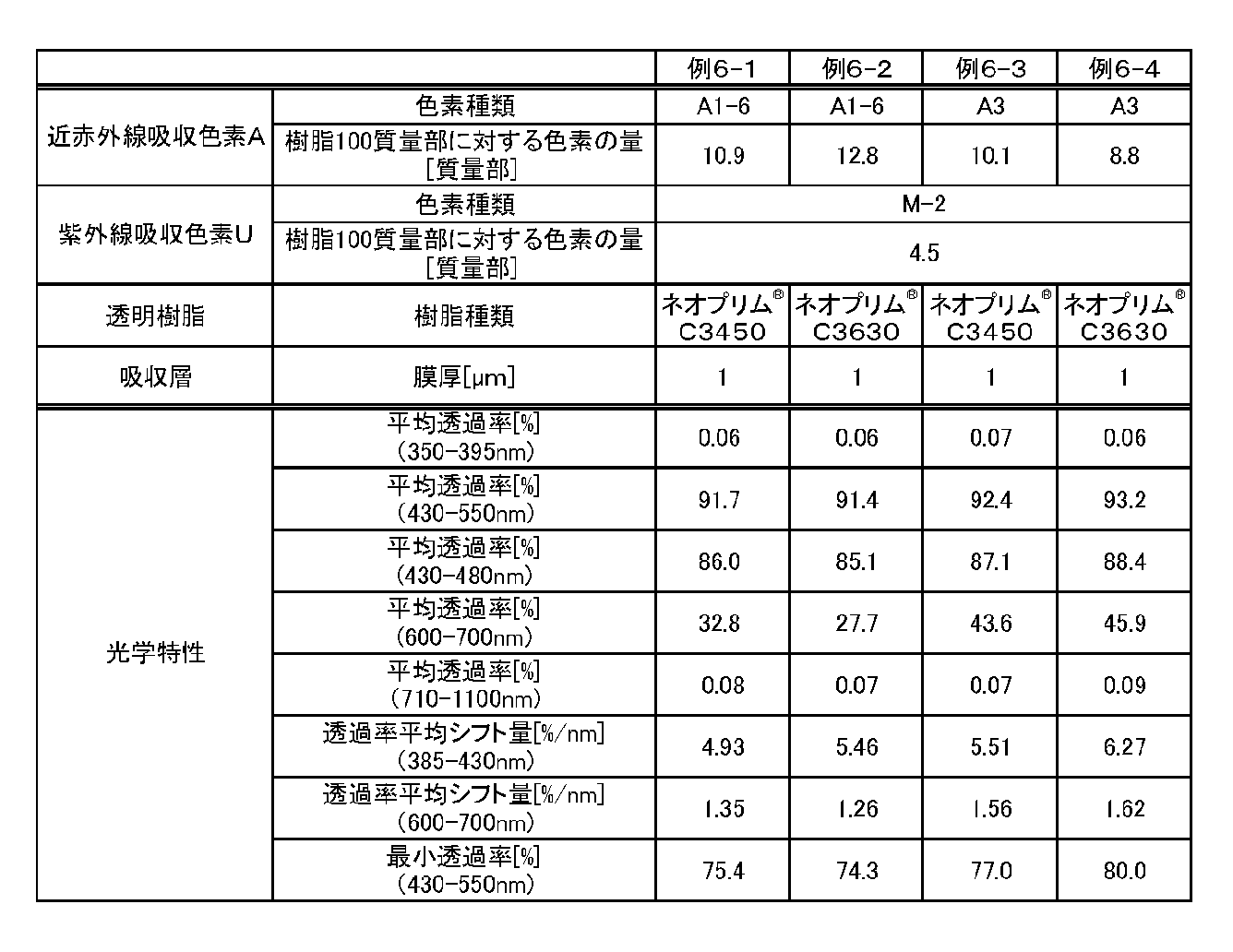
表10から明らかなように、例6-1、例6-2の光学フィルタは、いずれも(iv-1)~(iv-6)を満たしていた。すなわち、可視光の利用効率が高く、可視域の長波長領域における光の入射角依存性も低い光学フィルタであった。
<光学フィルタ[II]の耐光性の評価>
作製した光学フィルタ(例6-1~例6-4)について、耐光性試験を行い、耐光性を評価した。
耐光性試験では、スーパーキセノンウエザーメータSX75(スガ試験機(株)製、製品名)を用いて、光学フィルタに対し下記の条件で光を照射した。
波長:300~2450nm
温度:40℃
湿度:50%RT
積算光量:87.2kw・時間/m2
照射前後に、分光透過率曲線(入射角0°)を測定し、照射前後の波長500~800nmの光における最大透過率を求め、次式よりその変動量を算出した。
最大透過率変動量[%]=(照射前の波長500~800nmの光の最大透過率)-(照射後の波長500~800nmの光の最大透過率)
結果を、表11に示す。
作製した光学フィルタ(例6-1~例6-4)について、耐光性試験を行い、耐光性を評価した。
耐光性試験では、スーパーキセノンウエザーメータSX75(スガ試験機(株)製、製品名)を用いて、光学フィルタに対し下記の条件で光を照射した。
波長:300~2450nm
温度:40℃
湿度:50%RT
積算光量:87.2kw・時間/m2
照射前後に、分光透過率曲線(入射角0°)を測定し、照射前後の波長500~800nmの光における最大透過率を求め、次式よりその変動量を算出した。
最大透過率変動量[%]=(照射前の波長500~800nmの光の最大透過率)-(照射後の波長500~800nmの光の最大透過率)
結果を、表11に示す。

表11から明らかなように、本発明の実施例にかかるNIR色素(A1-6)を用いた光学フィルタは、優れた耐光性を示した。
<光学フィルタ[III]の製造>
(例7-1)
ポリイミド樹脂(C3630)を混合溶媒(シクロヘキサノン+NMP)に溶解して調製した溶液に、NIR吸収色素(A1-6)、およびUV色素(M-2)を、ポリイミド樹脂の質量に対してそれぞれ4.3質量%および4.5質量%となる割合で添加し溶解させて、吸収層を形成するための塗工液を調製した。
この塗工液を、厚さ0.2mmの近赤外線吸収ガラス(NF-50TX)基板上にスピンコート法により塗布し、大気圧下、加熱して、厚さ約0.9μmの吸収層を形成した。
この後、吸収層の表面に、TiO2膜とSiO2膜を交互に積層して反射防止層を形成し、光学フィルタを得た。
(例7-1)
ポリイミド樹脂(C3630)を混合溶媒(シクロヘキサノン+NMP)に溶解して調製した溶液に、NIR吸収色素(A1-6)、およびUV色素(M-2)を、ポリイミド樹脂の質量に対してそれぞれ4.3質量%および4.5質量%となる割合で添加し溶解させて、吸収層を形成するための塗工液を調製した。
この塗工液を、厚さ0.2mmの近赤外線吸収ガラス(NF-50TX)基板上にスピンコート法により塗布し、大気圧下、加熱して、厚さ約0.9μmの吸収層を形成した。
この後、吸収層の表面に、TiO2膜とSiO2膜を交互に積層して反射防止層を形成し、光学フィルタを得た。
(例7-2~例7-3)
例7-2~例7-3は、それぞれ吸収層を形成するための塗工液に添加するNIR吸収色素類および/または樹脂の種類を表12に示すように変えた以外は、例7-1と同様にして光学フィルタを製造した。
例7-2~例7-3は、それぞれ吸収層を形成するための塗工液に添加するNIR吸収色素類および/または樹脂の種類を表12に示すように変えた以外は、例7-1と同様にして光学フィルタを製造した。
<光学フィルタ[III]の分光特性の評価>
作製した光学フィルタ(例7-1~例7-3)について、分光透過率曲線(入射角0°および30°)を測定し、その測定結果から各光学特性を算出した。結果を、表12に示す。なお、表12中、平均透過率および最小透過率の値、ならびに波長385~430nmの透過率平均シフト量および波長600~700nmの透過率平均シフト量の定義は、表10におけるものと同様である。
作製した光学フィルタ(例7-1~例7-3)について、分光透過率曲線(入射角0°および30°)を測定し、その測定結果から各光学特性を算出した。結果を、表12に示す。なお、表12中、平均透過率および最小透過率の値、ならびに波長385~430nmの透過率平均シフト量および波長600~700nmの透過率平均シフト量の定義は、表10におけるものと同様である。
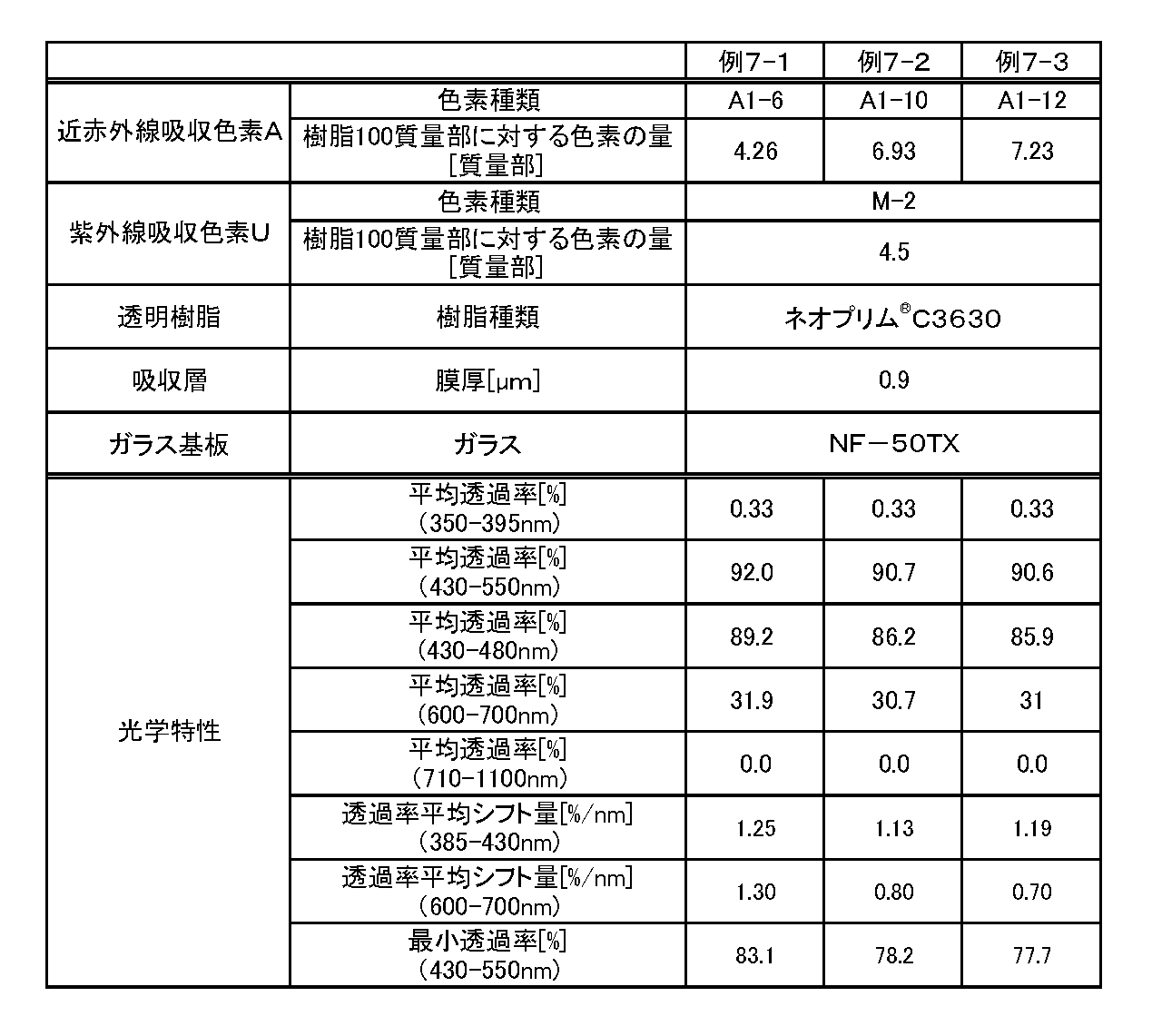
次に、光学フィルタ[III]について、光学フィルタ[I]と同様の密着性評価をすると、光学フィルタ[I]において示した条件(1)~(3)において、いずれも[A]判定の結果が得られることが確認できる。
条件(1):3.9N/cmのテープで剥離
条件(2):6.0N/cmのテープで剥離
条件(3):光学フィルタを30℃の水に10分間浸漬後、6.0N/cmのテープで剥離
条件(1):3.9N/cmのテープで剥離
条件(2):6.0N/cmのテープで剥離
条件(3):光学フィルタを30℃の水に10分間浸漬後、6.0N/cmのテープで剥離
本発明の光学フィルタは、良好な近赤外線遮蔽特性を有するとともに、当接する層との密着性に優れる吸収層を備えるので、デジタルスチルカメラ等の撮像装置、プラズマディスプレイ等の表示装置等の用途に有用である。
11…吸収層、12…選択波長遮蔽層、13…反射防止層、13…透明基材。
Claims (18)
- 近赤外線吸収色素と透明樹脂とを含有する吸収層と、前記吸収層に接する無機または有機材料とを備える光学フィルタであって、
前記近赤外線吸収色素が、式(AI)で示されるスクアリリウム系色素を含むことを特徴とする光学フィルタ。

Xは、独立して、1つ以上の水素原子が炭素数1~12のアルキル基またはアルコキシ基で置換されていてもよい式(1)または式(2)で示される2価の有機基である。
-(CH2)n1- …(1)
式(1)中、n1は2または3である。
-(CH2)n2-O-(CH2)n3- …(2)
式(2)中、n2とn3はそれぞれ独立して0~2の整数であり、n2+n3は1または2である。
R1は、独立して、飽和環構造を含んでもよく、分岐を有してもよい炭素数1~12の飽和もしくは不飽和炭化水素基、炭素数3~12の飽和環状炭化水素基、炭素数6~12のアリール基または炭素数7~13のアルアリール基を示す。
R2は、独立して、1つ以上の水素原子がハロゲン原子、水酸基、カルボキシ基、スルホ基、またはシアノ基で置換されていてもよく、炭素原子間に不飽和結合、酸素原子、飽和もしくは不飽和の環構造を含んでよい炭素数1~25の炭化水素基である。
R3およびR4は、独立して、水素原子、ハロゲン原子、または炭素数1~10のアルキル基もしくはアルコキシ基を示す。 - 前記式(AI)中、Xが、式(3)で示される2価の有機基である請求項1に記載の光学フィルタ。
-CR5 2-(CR6 2)n4- …(3)
ただし、式(3)は、左側がベンゼン環に結合し右側がNに結合する2価の基を示し、
n4は1または2であり、
R5は、それぞれ独立して、分岐を有してもよい炭素数1~12のアルキル基またはアルコキシ基であり、
R6はそれぞれ独立して、水素原子または、分岐を有してもよい炭素数1~12のアルキル基またはアルコキシ基である。 - 前記式(3)中、R5が、それぞれ独立して、分岐を有してもよい炭素数1~6のアルキル基またはアルコキシ基であり、R6が、それぞれ独立して、水素原子、または分岐を有してもよい炭素数1~6のアルキル基またはアルコキシ基である請求項2に記載の光学フィルタ。
- 式(AI)中、Xが、式(11-1)~式(12-3)で示される2価の有機基のいずれかである請求項1に記載の光学フィルタ。
-C(CH3)2-CH(CH3)- …(11-1)
-C(CH3)2-CH2- …(11-2)
-C(CH3)2-CH(C2H5)- …(11-3)
-C(CH3)2-CH2-CH2- …(12-1)
-C(CH3)2-CH2-CH(CH3)- …(12-2)
-C(CH3)2-CH(CH3)-CH2- …(12-3)
ただし、式(11-1)~式(12-3)で示される基は、いずれも左側がベンゼン環に結合し右側がNに結合する。 - 前記式(AI)中、R1が、独立して、式(4-1)または式(4-2)で示される基である請求項1~4のいずれか1項に記載の光学フィルタ。

- 前記式(AI)中、R2が、独立して、分岐を有してもよい炭素数1~12のアルキル基もしくはアルコキシ基である請求項1~5のいずれか1項に記載の光学フィルタ。
- 前記式(AI)で示されるスクアリリウム系色素は、ジクロロメタンに溶解して測定される吸収特性が(i-1)~(i-3)を満たす請求項1~6のいずれか1項に記載の光学フィルタ。
(i-1)波長400~800nmの吸収スペクトルにおいて、波長670~730nmに最大吸収波長λmaxを有する。
(i-2)波長430~550nmの光の最大吸光係数εAと、波長690~730nmの光の最大吸光係数εBとの間に、次の関係式が成り立つ。
εB/εA≧50
(i-3)分光透過率曲線において、前記最大吸収波長λmaxにおける透過率を10%としたときの前記最大吸収波長より短波長側で透過率が80%となる波長λ80と、前記最大吸収波長λmaxとの差が60nm以下である。 - 前記近赤外線吸収色素が、アクリル樹脂、エポキシ樹脂、エン・チオール樹脂、ポリカーボネート樹脂、ポリエーテル樹脂、ポリアリレート樹脂、ポリスルホン樹脂、ポリエーテルスルホン樹脂、ポリパラフェニレン樹脂、ポリアリーレンエーテルフォスフィンオキシド樹脂、ポリイミド樹脂、ポリアミドイミド樹脂、ポリオレフィン樹脂、環状オレフィン樹脂およびポリエステル樹脂からなる群より選択される少なくとも1種を含む透明樹脂に溶解または分散されている請求項1~7のいずれか1項に記載の光学フィルタ。
- 前記吸収層が、ビニル基、エポキシ基、スチリル基、メタクリル基、アクリル基、アミノ基、ウレイド基、メルカプト基、スルフィド基およびイソシアネート基からなる群より選択される少なくとも1種を有するシランカップリング剤を含む請求項1~8のいずれか1項に記載の光学フィルタ。
- 前記吸収層が、(ii-1)を満たす紫外線吸収色素を含む請求項1~9のいずれか1項に記載の光学フィルタ。
(ii-1)ジクロロメタンに溶解して測定される波長350~800nmの吸収スペクトルにおいて、360~415nmの波長領域に最大吸収波長を有する。 - 前記紫外線吸収色素が、式(M)で示される合物である請求項10に記載の光学フィルタ。
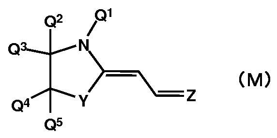
Yは、Q6およびQ7で置換されたメチレン基または酸素原子(ここで、Q6およびQ7は、それぞれ独立に、水素原子、ハロゲン原子、または炭素数1~10のアルキル基もしくはアルコキシ基)を示し、
Q1は、置換基を有していてもよい炭素数1~12の1価の炭化水素基を示し、
Q2~Q5は、それぞれ独立に、水素原子、ハロゲン原子、または、炭素数1~10のアルキル基もしくはアルコキシ基を示し、
Zは、式(Z1)~式(Z5)のいずれかで表される2価の基を示す。
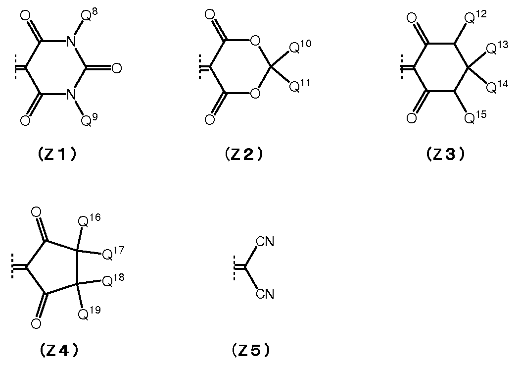
- 前記吸収層が、透明基材または誘電体多層膜と接する請求項1~10のいずれか1項に記載の光学フィルタ。
- 前記透明基材は、ガラスを含む請求項12に記載の光学フィルタ。
- 前記ガラスは、近赤外線吸収ガラスである請求項13に記載の光学フィルタ。
- (iii-1)および(iii-2)を満たす選択波長遮蔽層を有する請求項1~14のいずれか1項に記載の光学フィルタ。
(iii-1)入射角0°および30°の各分光透過率曲線において、波長420~695nmの光の透過率が90%以上である。
(iii-2)入射角0°および30°の各分光透過率曲線において、波長λbnm~1100nmの光の透過率が1%以下である(ここで、λbは、前記吸収層の波長650~800nmの光の透過率が1%となる最大波長である)。 - (iv-1)を満たす分光特性を有する請求項1~14のいずれか1項に記載の光学フィルタ。
(iv-1)入射角0°の分光透過率曲線において、波長430~550nmの光の平均透過率が90%以上であり、かつ波長430~550nmの光の最小透過率が75%以上である。 - 前記分光特性は、(iv-2)~(iv-6)のいずれかをさらに満たす請求項16に記載の光学フィルタ。
(iv-2)入射角0°の分光透過率曲線において、波長600~700nmの光の平均透過率が25%以上である。
(iv-3)入射角0°の分光透過率曲線において、波長350~395nmの光の平均透過率が2%以下である。
(iv-4)入射角0°の分光透過率曲線において、波長710~1100nmの光の平均透過率が2%以下である。
(iv-5)入射角0°の分光透過率曲線の波長385~430nmの光の透過率と、入射角30°の分光透過率曲線における波長385~430nmの光の透過率との差分の絶対値の平均値が7%/nm以下である。
(iv-6)入射角0°の分光透過率曲線の波長600~700nmの光の透過率と、入射角30°の分光透過率曲線における波長600~700nmの光の透過率との差分の絶対値の平均値が7%/nm以下である。 - 固体撮像素子と、請求項1~17のいずれか1項に記載の光学フィルタを備えたことを特徴とする撮像装置。
Priority Applications (5)
| Application Number | Priority Date | Filing Date | Title |
|---|---|---|---|
| CN202010572909.XA CN111665583B (zh) | 2015-05-12 | 2016-05-11 | 近红外线吸收色素和吸收层 |
| CN201680026755.6A CN107533171B (zh) | 2015-05-12 | 2016-05-11 | 光学滤波器以及摄像装置 |
| JP2017517961A JP6720969B2 (ja) | 2015-05-12 | 2016-05-11 | 光学フィルタおよび撮像装置 |
| US15/806,596 US10809428B2 (en) | 2015-05-12 | 2017-11-08 | Optical filter and imaging device |
| US17/017,031 US11693163B2 (en) | 2015-05-12 | 2020-09-10 | Optical filter and imaging device |
Applications Claiming Priority (2)
| Application Number | Priority Date | Filing Date | Title |
|---|---|---|---|
| JP2015097777 | 2015-05-12 | ||
| JP2015-097777 | 2015-05-12 |
Related Child Applications (1)
| Application Number | Title | Priority Date | Filing Date |
|---|---|---|---|
| US15/806,596 Continuation US10809428B2 (en) | 2015-05-12 | 2017-11-08 | Optical filter and imaging device |
Publications (1)
| Publication Number | Publication Date |
|---|---|
| WO2016181987A1 true WO2016181987A1 (ja) | 2016-11-17 |
Family
ID=57248053
Family Applications (1)
| Application Number | Title | Priority Date | Filing Date |
|---|---|---|---|
| PCT/JP2016/063977 Ceased WO2016181987A1 (ja) | 2015-05-12 | 2016-05-11 | 光学フィルタおよび撮像装置 |
Country Status (4)
| Country | Link |
|---|---|
| US (2) | US10809428B2 (ja) |
| JP (2) | JP6720969B2 (ja) |
| CN (2) | CN111665583B (ja) |
| WO (1) | WO2016181987A1 (ja) |
Cited By (23)
| Publication number | Priority date | Publication date | Assignee | Title |
|---|---|---|---|---|
| JP2019031637A (ja) * | 2017-08-09 | 2019-02-28 | 株式会社日本触媒 | スクアリリウム化合物 |
| WO2019049884A1 (ja) * | 2017-09-11 | 2019-03-14 | Agc株式会社 | 光学フィルタおよび撮像装置 |
| WO2019054281A1 (ja) | 2017-09-15 | 2019-03-21 | 富士フイルム株式会社 | 組成物、膜、積層体、赤外線透過フィルタ、固体撮像素子および赤外線センサ |
| JP2019049586A (ja) * | 2017-09-07 | 2019-03-28 | 株式会社日本触媒 | 光選択透過フィルター |
| JP2019174798A (ja) * | 2018-03-27 | 2019-10-10 | 三星電子株式会社Samsung Electronics Co.,Ltd. | 近赤外線吸収フィルム及び光学フィルタ並びに電子装置 |
| CN110554450A (zh) * | 2018-06-04 | 2019-12-10 | 豪雅冠得股份有限公司 | 滤光片及摄像装置 |
| JP2019211773A (ja) * | 2018-06-04 | 2019-12-12 | Hoya Candeo Optronics株式会社 | 光学フィルターおよび撮像装置 |
| WO2020059509A1 (ja) | 2018-09-20 | 2020-03-26 | 富士フイルム株式会社 | 硬化性組成物、硬化膜、赤外線透過フィルタ、積層体、固体撮像素子、センサ、及び、パターン形成方法 |
| WO2020241535A1 (ja) | 2019-05-31 | 2020-12-03 | 富士フイルム株式会社 | 光センサおよびセンシング装置 |
| WO2021039253A1 (ja) | 2019-08-30 | 2021-03-04 | 富士フイルム株式会社 | 組成物、膜、光学フィルタ及びその製造方法、固体撮像素子、赤外線センサ、並びに、センサモジュール |
| WO2021039205A1 (ja) | 2019-08-29 | 2021-03-04 | 富士フイルム株式会社 | 組成物、膜、近赤外線カットフィルタ、パターン形成方法、積層体、固体撮像素子、赤外線センサ、画像表示装置、カメラモジュール、及び、化合物 |
| WO2022131191A1 (ja) | 2020-12-16 | 2022-06-23 | 富士フイルム株式会社 | 組成物、膜、光学フィルタ、固体撮像素子、画像表示装置および赤外線センサ |
| WO2022130773A1 (ja) | 2020-12-17 | 2022-06-23 | 富士フイルム株式会社 | 組成物、膜、光学フィルタ、固体撮像素子、画像表示装置および赤外線センサ |
| WO2022196599A1 (ja) | 2021-03-19 | 2022-09-22 | 富士フイルム株式会社 | 膜および光センサ |
| WO2023054142A1 (ja) | 2021-09-29 | 2023-04-06 | 富士フイルム株式会社 | 組成物、樹脂、膜および光センサ |
| JP2023160876A (ja) * | 2019-09-11 | 2023-11-02 | Agc株式会社 | 光学フィルタおよび撮像装置 |
| WO2023234094A1 (ja) | 2022-06-01 | 2023-12-07 | 富士フイルム株式会社 | 光検出素子、イメージセンサおよび光検出素子の製造方法 |
| WO2023234096A1 (ja) | 2022-06-01 | 2023-12-07 | 富士フイルム株式会社 | 光検出素子、イメージセンサおよび光検出素子の製造方法 |
| WO2023234095A1 (ja) | 2022-06-01 | 2023-12-07 | 富士フイルム株式会社 | 光検出素子、イメージセンサおよび光検出素子の製造方法 |
| WO2024043110A1 (ja) | 2022-08-22 | 2024-02-29 | 富士フイルム株式会社 | 感光性組成物、膜および光センサ |
| WO2024053471A1 (ja) | 2022-09-09 | 2024-03-14 | 富士フイルム株式会社 | 光硬化性組成物、膜、光センサおよび光センサの製造方法 |
| JP2024055846A (ja) * | 2022-10-06 | 2024-04-18 | エルエムエス・カンパニー・リミテッド | 光学フィルタおよび撮像装置 |
| WO2025183143A1 (ja) * | 2024-02-29 | 2025-09-04 | Hoya株式会社 | 光学フィルタ及びそれを備える光脱毛装置 |
Families Citing this family (10)
| Publication number | Priority date | Publication date | Assignee | Title |
|---|---|---|---|---|
| JP6720969B2 (ja) * | 2015-05-12 | 2020-07-08 | Agc株式会社 | 光学フィルタおよび撮像装置 |
| WO2017135359A1 (ja) * | 2016-02-02 | 2017-08-10 | 旭硝子株式会社 | 近赤外線吸収色素、光学フィルタおよび撮像装置 |
| EP3282292B1 (en) * | 2016-08-09 | 2021-07-07 | Essilor International | Optical article comprising an interferential coating with a high reflection in the near infrared region (nir) |
| KR102476708B1 (ko) * | 2017-11-01 | 2022-12-09 | 삼성전자주식회사 | 광학 필터, 및 이를 포함하는 카메라 모듈 및 전자 장치 |
| JP7222362B2 (ja) * | 2018-02-05 | 2023-02-15 | Agc株式会社 | 光学フィルタおよび撮像装置 |
| WO2020009015A1 (ja) * | 2018-07-06 | 2020-01-09 | 富士フイルム株式会社 | 硬化性組成物、膜、近赤外線カットフィルタ、固体撮像素子、画像表示装置、赤外線センサ及びカメラモジュール |
| CN112689780A (zh) | 2018-09-12 | 2021-04-20 | Agc株式会社 | 光学滤波器和摄像装置 |
| WO2020204025A1 (ja) * | 2019-04-03 | 2020-10-08 | Agc株式会社 | 光学フィルタおよび撮像装置 |
| CN114616291B (zh) * | 2019-11-01 | 2023-07-04 | Jsr株式会社 | 树脂组合物、化合物、光学滤波器、及光学传感装置 |
| TWI752677B (zh) | 2020-11-12 | 2022-01-11 | 晶瑞光電股份有限公司 | 紅外截止濾光片結構 |
Citations (9)
| Publication number | Priority date | Publication date | Assignee | Title |
|---|---|---|---|---|
| JPH01228960A (ja) * | 1988-03-09 | 1989-09-12 | Konica Corp | スクアリリウムの化合物 |
| US5543086A (en) * | 1987-08-12 | 1996-08-06 | Gentex Corporation | Squarylium dyestuffs and compostions containing same |
| DE10057141A1 (de) * | 2000-11-17 | 2002-05-23 | Few Chemicals Gmbh | UV- und blaulichtempfindliche Photosensibilitoren für die Photopolymerisation |
| DE10109243A1 (de) * | 2001-02-26 | 2002-09-05 | Few Chemicals Gmbh | UV- und blaues Licht absorbierende Merocyaninverbindungen |
| JP2013019991A (ja) * | 2011-07-08 | 2013-01-31 | Japan Carlit Co Ltd:The | 近赤外線吸収樹脂組成物及び近赤外線遮断フィルター |
| US20140061505A1 (en) * | 2012-09-04 | 2014-03-06 | Exciton, Inc. | Squarylium dyes |
| JP2014059550A (ja) * | 2012-08-23 | 2014-04-03 | Asahi Glass Co Ltd | 近赤外線カットフィルタ |
| JP2014066918A (ja) * | 2012-09-26 | 2014-04-17 | Asahi Glass Co Ltd | 撮像レンズおよび撮像装置 |
| WO2014088063A1 (ja) * | 2012-12-06 | 2014-06-12 | 旭硝子株式会社 | 近赤外線カットフィルタ |
Family Cites Families (27)
| Publication number | Priority date | Publication date | Assignee | Title |
|---|---|---|---|---|
| JP2001183522A (ja) * | 1999-12-27 | 2001-07-06 | Mitsubishi Chemicals Corp | プラズマディスプレイパネル用フィルター |
| AU2001282593A1 (en) * | 2000-09-04 | 2002-03-22 | Mitsubishi Chemical Corporation | Diphenylsquarylium compound and display filter containing the same |
| JP2002228829A (ja) * | 2001-02-02 | 2002-08-14 | Asahi Denka Kogyo Kk | 光学フィルター |
| US20060121392A1 (en) * | 2004-11-24 | 2006-06-08 | Dai Nippon Printing Co., Ltd. | Optical filter and display using the same |
| CN101107258A (zh) * | 2005-02-04 | 2008-01-16 | 株式会社日本触媒 | 硼酸盐和近红外线吸收材料 |
| WO2006118277A1 (ja) * | 2005-04-28 | 2006-11-09 | Api Corporation | 近赤外線吸収色素含有粘着剤 |
| JP4908414B2 (ja) * | 2005-05-13 | 2012-04-04 | 日本化薬株式会社 | ジイモニウム化合物及びその用途 |
| CN101233208A (zh) * | 2005-08-10 | 2008-07-30 | 东洋油墨制造株式会社 | 近红外线吸收材料及其用途 |
| JP4785541B2 (ja) * | 2006-01-26 | 2011-10-05 | 株式会社Adeka | 光学フィルター |
| CN101511962A (zh) * | 2006-08-31 | 2009-08-19 | 株式会社日本触媒 | 用于近红外线吸收性组合物的盐和近红外线吸收性压敏粘合剂组合物 |
| JP5475244B2 (ja) * | 2007-03-30 | 2014-04-16 | 株式会社Adeka | シアニン化合物、該化合物を用いた光学フィルター及び光学記録材料 |
| US20110315939A1 (en) * | 2009-02-20 | 2011-12-29 | Japan Carlit Co., Ltd. | Near infrared absorbent dye and near infrared shielding filter |
| US20120251831A1 (en) * | 2009-12-16 | 2012-10-04 | Japan Carlit Co., Ltd | Near-infrared absorptive coloring matter and near-infrared absorptive composition |
| JP5535664B2 (ja) | 2010-01-15 | 2014-07-02 | 株式会社Adeka | 色調補正剤、スクアリリウム化合物及び光学フィルター |
| WO2011142463A1 (ja) * | 2010-05-14 | 2011-11-17 | 旭硝子株式会社 | 紫外線吸収膜形成用塗布液および紫外線吸収ガラス物品 |
| JP5810604B2 (ja) * | 2010-05-26 | 2015-11-11 | Jsr株式会社 | 近赤外線カットフィルターおよび近赤外線カットフィルターを用いた装置 |
| EP2587285A4 (en) * | 2010-06-25 | 2014-10-15 | Asahi Glass Co Ltd | OPTICAL FILM AND MANUFACTURING METHOD THEREFOR |
| JP6036689B2 (ja) * | 2011-06-06 | 2016-11-30 | 旭硝子株式会社 | 光学フィルタ、固体撮像素子、撮像装置用レンズおよび撮像装置 |
| TWI588192B (zh) | 2011-10-14 | 2017-06-21 | Jsr Corp | Optical filter, solid-state imaging device and camera module using the optical filter |
| JP6305331B2 (ja) * | 2012-04-25 | 2018-04-04 | 株式会社Adeka | 波長カットフィルタ |
| WO2013183557A1 (ja) * | 2012-06-04 | 2013-12-12 | 旭硝子株式会社 | 近赤外線カットフィルタ |
| CN108761612B (zh) | 2012-08-23 | 2021-04-06 | Agc株式会社 | 近红外线截止滤波器和固体摄像装置 |
| JP6183048B2 (ja) * | 2012-08-27 | 2017-08-23 | 旭硝子株式会社 | 光学フィルタおよび固体撮像装置 |
| CN103923438B (zh) * | 2013-01-11 | 2018-09-07 | 株式会社日本触媒 | 叠层用树脂组合物及其用途 |
| JP2014148567A (ja) * | 2013-01-31 | 2014-08-21 | Nippon Kayaku Co Ltd | 樹脂組成物及び近赤外線カットフィルタ |
| JP2015040895A (ja) * | 2013-08-20 | 2015-03-02 | Jsr株式会社 | 光学フィルターおよび光学フィルターを用いた装置 |
| JP6720969B2 (ja) * | 2015-05-12 | 2020-07-08 | Agc株式会社 | 光学フィルタおよび撮像装置 |
-
2016
- 2016-05-11 JP JP2017517961A patent/JP6720969B2/ja active Active
- 2016-05-11 CN CN202010572909.XA patent/CN111665583B/zh active Active
- 2016-05-11 CN CN201680026755.6A patent/CN107533171B/zh active Active
- 2016-05-11 WO PCT/JP2016/063977 patent/WO2016181987A1/ja not_active Ceased
-
2017
- 2017-11-08 US US15/806,596 patent/US10809428B2/en active Active
-
2020
- 2020-06-15 JP JP2020103353A patent/JP6904465B2/ja active Active
- 2020-09-10 US US17/017,031 patent/US11693163B2/en active Active
Patent Citations (9)
| Publication number | Priority date | Publication date | Assignee | Title |
|---|---|---|---|---|
| US5543086A (en) * | 1987-08-12 | 1996-08-06 | Gentex Corporation | Squarylium dyestuffs and compostions containing same |
| JPH01228960A (ja) * | 1988-03-09 | 1989-09-12 | Konica Corp | スクアリリウムの化合物 |
| DE10057141A1 (de) * | 2000-11-17 | 2002-05-23 | Few Chemicals Gmbh | UV- und blaulichtempfindliche Photosensibilitoren für die Photopolymerisation |
| DE10109243A1 (de) * | 2001-02-26 | 2002-09-05 | Few Chemicals Gmbh | UV- und blaues Licht absorbierende Merocyaninverbindungen |
| JP2013019991A (ja) * | 2011-07-08 | 2013-01-31 | Japan Carlit Co Ltd:The | 近赤外線吸収樹脂組成物及び近赤外線遮断フィルター |
| JP2014059550A (ja) * | 2012-08-23 | 2014-04-03 | Asahi Glass Co Ltd | 近赤外線カットフィルタ |
| US20140061505A1 (en) * | 2012-09-04 | 2014-03-06 | Exciton, Inc. | Squarylium dyes |
| JP2014066918A (ja) * | 2012-09-26 | 2014-04-17 | Asahi Glass Co Ltd | 撮像レンズおよび撮像装置 |
| WO2014088063A1 (ja) * | 2012-12-06 | 2014-06-12 | 旭硝子株式会社 | 近赤外線カットフィルタ |
Cited By (40)
| Publication number | Priority date | Publication date | Assignee | Title |
|---|---|---|---|---|
| JP2019031637A (ja) * | 2017-08-09 | 2019-02-28 | 株式会社日本触媒 | スクアリリウム化合物 |
| JP2019049586A (ja) * | 2017-09-07 | 2019-03-28 | 株式会社日本触媒 | 光選択透過フィルター |
| JP7015128B2 (ja) | 2017-09-07 | 2022-02-02 | 株式会社日本触媒 | 光選択透過フィルター |
| JP7070555B2 (ja) | 2017-09-11 | 2022-05-18 | Agc株式会社 | 光学フィルタおよび撮像装置 |
| JP7468568B2 (ja) | 2017-09-11 | 2024-04-16 | Agc株式会社 | 光学フィルタおよび撮像装置 |
| US11709298B2 (en) | 2017-09-11 | 2023-07-25 | AGC Inc. | Optical filter and imaging device |
| JP2022115885A (ja) * | 2017-09-11 | 2022-08-09 | Agc株式会社 | 光学フィルタおよび撮像装置 |
| CN111095045A (zh) * | 2017-09-11 | 2020-05-01 | Agc株式会社 | 光学滤波器和摄像装置 |
| JPWO2019049884A1 (ja) * | 2017-09-11 | 2020-08-27 | Agc株式会社 | 光学フィルタおよび撮像装置 |
| US12204124B2 (en) | 2017-09-11 | 2025-01-21 | AGC Inc. | Optical filter and imaging device |
| WO2019049884A1 (ja) * | 2017-09-11 | 2019-03-14 | Agc株式会社 | 光学フィルタおよび撮像装置 |
| CN111095045B (zh) * | 2017-09-11 | 2022-05-17 | Agc株式会社 | 光学滤波器和摄像装置 |
| WO2019054281A1 (ja) | 2017-09-15 | 2019-03-21 | 富士フイルム株式会社 | 組成物、膜、積層体、赤外線透過フィルタ、固体撮像素子および赤外線センサ |
| JP7252015B2 (ja) | 2018-03-27 | 2023-04-04 | 三星電子株式会社 | 近赤外線吸収フィルム及び光学フィルタ並びに電子装置 |
| JP2019174798A (ja) * | 2018-03-27 | 2019-10-10 | 三星電子株式会社Samsung Electronics Co.,Ltd. | 近赤外線吸収フィルム及び光学フィルタ並びに電子装置 |
| JP2024178152A (ja) * | 2018-06-04 | 2024-12-24 | Hoya株式会社 | 光学フィルターおよび撮像装置 |
| JP7536136B2 (ja) | 2018-06-04 | 2024-08-19 | Hoya株式会社 | 光学フィルターおよび撮像装置 |
| JP2023076761A (ja) * | 2018-06-04 | 2023-06-01 | Hoya株式会社 | 光学フィルターおよび撮像装置 |
| JP7466275B2 (ja) | 2018-06-04 | 2024-04-12 | Hoya株式会社 | 光学フィルターおよび撮像装置 |
| JP2019211773A (ja) * | 2018-06-04 | 2019-12-12 | Hoya Candeo Optronics株式会社 | 光学フィルターおよび撮像装置 |
| CN110554450A (zh) * | 2018-06-04 | 2019-12-10 | 豪雅冠得股份有限公司 | 滤光片及摄像装置 |
| CN110554450B (zh) * | 2018-06-04 | 2023-05-19 | Hoya株式会社 | 滤光片及摄像装置 |
| WO2020059509A1 (ja) | 2018-09-20 | 2020-03-26 | 富士フイルム株式会社 | 硬化性組成物、硬化膜、赤外線透過フィルタ、積層体、固体撮像素子、センサ、及び、パターン形成方法 |
| WO2020241535A1 (ja) | 2019-05-31 | 2020-12-03 | 富士フイルム株式会社 | 光センサおよびセンシング装置 |
| WO2021039205A1 (ja) | 2019-08-29 | 2021-03-04 | 富士フイルム株式会社 | 組成物、膜、近赤外線カットフィルタ、パターン形成方法、積層体、固体撮像素子、赤外線センサ、画像表示装置、カメラモジュール、及び、化合物 |
| WO2021039253A1 (ja) | 2019-08-30 | 2021-03-04 | 富士フイルム株式会社 | 組成物、膜、光学フィルタ及びその製造方法、固体撮像素子、赤外線センサ、並びに、センサモジュール |
| JP2023160876A (ja) * | 2019-09-11 | 2023-11-02 | Agc株式会社 | 光学フィルタおよび撮像装置 |
| JP7559896B2 (ja) | 2019-09-11 | 2024-10-02 | Agc株式会社 | 光学フィルタおよび撮像装置 |
| WO2022131191A1 (ja) | 2020-12-16 | 2022-06-23 | 富士フイルム株式会社 | 組成物、膜、光学フィルタ、固体撮像素子、画像表示装置および赤外線センサ |
| WO2022130773A1 (ja) | 2020-12-17 | 2022-06-23 | 富士フイルム株式会社 | 組成物、膜、光学フィルタ、固体撮像素子、画像表示装置および赤外線センサ |
| WO2022196599A1 (ja) | 2021-03-19 | 2022-09-22 | 富士フイルム株式会社 | 膜および光センサ |
| WO2023054142A1 (ja) | 2021-09-29 | 2023-04-06 | 富士フイルム株式会社 | 組成物、樹脂、膜および光センサ |
| WO2023234095A1 (ja) | 2022-06-01 | 2023-12-07 | 富士フイルム株式会社 | 光検出素子、イメージセンサおよび光検出素子の製造方法 |
| WO2023234096A1 (ja) | 2022-06-01 | 2023-12-07 | 富士フイルム株式会社 | 光検出素子、イメージセンサおよび光検出素子の製造方法 |
| WO2023234094A1 (ja) | 2022-06-01 | 2023-12-07 | 富士フイルム株式会社 | 光検出素子、イメージセンサおよび光検出素子の製造方法 |
| WO2024043110A1 (ja) | 2022-08-22 | 2024-02-29 | 富士フイルム株式会社 | 感光性組成物、膜および光センサ |
| WO2024053471A1 (ja) | 2022-09-09 | 2024-03-14 | 富士フイルム株式会社 | 光硬化性組成物、膜、光センサおよび光センサの製造方法 |
| JP2024055846A (ja) * | 2022-10-06 | 2024-04-18 | エルエムエス・カンパニー・リミテッド | 光学フィルタおよび撮像装置 |
| JP7788735B2 (ja) | 2022-10-06 | 2025-12-19 | エルエムエス・カンパニー・リミテッド | 光学フィルタおよび撮像装置 |
| WO2025183143A1 (ja) * | 2024-02-29 | 2025-09-04 | Hoya株式会社 | 光学フィルタ及びそれを備える光脱毛装置 |
Also Published As
| Publication number | Publication date |
|---|---|
| US10809428B2 (en) | 2020-10-20 |
| US20180067243A1 (en) | 2018-03-08 |
| CN107533171B (zh) | 2020-07-24 |
| US20200408974A1 (en) | 2020-12-31 |
| CN111665583A (zh) | 2020-09-15 |
| CN107533171A (zh) | 2018-01-02 |
| US11693163B2 (en) | 2023-07-04 |
| JP2020152915A (ja) | 2020-09-24 |
| JP6904465B2 (ja) | 2021-07-14 |
| JPWO2016181987A1 (ja) | 2018-03-29 |
| JP6720969B2 (ja) | 2020-07-08 |
| CN111665583B (zh) | 2022-03-15 |
Similar Documents
| Publication | Publication Date | Title |
|---|---|---|
| JP6904465B2 (ja) | 近赤外線吸収色素および吸収層 | |
| JP6197940B2 (ja) | スクアリリウム系色素、樹脂膜、光学フィルタおよび撮像装置 | |
| JP6168252B2 (ja) | 近赤外線カットフィルタおよび撮像装置 | |
| JP6787347B2 (ja) | 近赤外線吸収色素、光学フィルタおよび撮像装置 | |
| JP6202230B1 (ja) | 光学フィルタおよび撮像装置 | |
| JPWO2019151344A1 (ja) | 光学フィルタおよび撮像装置 | |
| JP7342958B2 (ja) | 光学フィルタおよび撮像装置 | |
| JP2019164269A (ja) | 光学フィルタ、近赤外線吸収色素および撮像装置 | |
| JP2019078816A (ja) | 光学フィルタおよび撮像装置 | |
| US20250199219A1 (en) | Optical filter | |
| JP7459709B2 (ja) | 光学フィルタ | |
| JP7392381B2 (ja) | 光学フィルタおよび撮像装置 | |
| JP2018028605A (ja) | 光学フィルタ用組成物および光学フィルタ | |
| WO2022034739A1 (ja) | 光学フィルタ |
Legal Events
| Date | Code | Title | Description |
|---|---|---|---|
| 121 | Ep: the epo has been informed by wipo that ep was designated in this application |
Ref document number: 16792712 Country of ref document: EP Kind code of ref document: A1 |
|
| ENP | Entry into the national phase |
Ref document number: 2017517961 Country of ref document: JP Kind code of ref document: A |
|
| NENP | Non-entry into the national phase |
Ref country code: DE |
|
| 122 | Ep: pct application non-entry in european phase |
Ref document number: 16792712 Country of ref document: EP Kind code of ref document: A1 |