WO2016147564A1 - 非水電解質二次電池 - Google Patents
非水電解質二次電池 Download PDFInfo
- Publication number
- WO2016147564A1 WO2016147564A1 PCT/JP2016/000922 JP2016000922W WO2016147564A1 WO 2016147564 A1 WO2016147564 A1 WO 2016147564A1 JP 2016000922 W JP2016000922 W JP 2016000922W WO 2016147564 A1 WO2016147564 A1 WO 2016147564A1
- Authority
- WO
- WIPO (PCT)
- Prior art keywords
- negative electrode
- silicon
- electrode plate
- current collector
- secondary battery
- Prior art date
- Legal status (The legal status is an assumption and is not a legal conclusion. Google has not performed a legal analysis and makes no representation as to the accuracy of the status listed.)
- Ceased
Links
Images


Classifications
-
- H—ELECTRICITY
- H01—ELECTRIC ELEMENTS
- H01M—PROCESSES OR MEANS, e.g. BATTERIES, FOR THE DIRECT CONVERSION OF CHEMICAL ENERGY INTO ELECTRICAL ENERGY
- H01M4/00—Electrodes
- H01M4/02—Electrodes composed of, or comprising, active material
- H01M4/36—Selection of substances as active materials, active masses, active liquids
- H01M4/362—Composites
- H01M4/364—Composites as mixtures
-
- H—ELECTRICITY
- H01—ELECTRIC ELEMENTS
- H01M—PROCESSES OR MEANS, e.g. BATTERIES, FOR THE DIRECT CONVERSION OF CHEMICAL ENERGY INTO ELECTRICAL ENERGY
- H01M10/00—Secondary cells; Manufacture thereof
- H01M10/04—Construction or manufacture in general
- H01M10/0431—Cells with wound or folded electrodes
-
- H—ELECTRICITY
- H01—ELECTRIC ELEMENTS
- H01M—PROCESSES OR MEANS, e.g. BATTERIES, FOR THE DIRECT CONVERSION OF CHEMICAL ENERGY INTO ELECTRICAL ENERGY
- H01M10/00—Secondary cells; Manufacture thereof
- H01M10/05—Accumulators with non-aqueous electrolyte
- H01M10/052—Li-accumulators
- H01M10/0525—Rocking-chair batteries, i.e. batteries with lithium insertion or intercalation in both electrodes; Lithium-ion batteries
-
- H—ELECTRICITY
- H01—ELECTRIC ELEMENTS
- H01M—PROCESSES OR MEANS, e.g. BATTERIES, FOR THE DIRECT CONVERSION OF CHEMICAL ENERGY INTO ELECTRICAL ENERGY
- H01M10/00—Secondary cells; Manufacture thereof
- H01M10/05—Accumulators with non-aqueous electrolyte
- H01M10/058—Construction or manufacture
- H01M10/0587—Construction or manufacture of accumulators having only wound construction elements, i.e. wound positive electrodes, wound negative electrodes and wound separators
-
- H—ELECTRICITY
- H01—ELECTRIC ELEMENTS
- H01M—PROCESSES OR MEANS, e.g. BATTERIES, FOR THE DIRECT CONVERSION OF CHEMICAL ENERGY INTO ELECTRICAL ENERGY
- H01M4/00—Electrodes
- H01M4/02—Electrodes composed of, or comprising, active material
- H01M4/13—Electrodes for accumulators with non-aqueous electrolyte, e.g. for lithium-accumulators; Processes of manufacture thereof
- H01M4/131—Electrodes based on mixed oxides or hydroxides, or on mixtures of oxides or hydroxides, e.g. LiCoOx
-
- H—ELECTRICITY
- H01—ELECTRIC ELEMENTS
- H01M—PROCESSES OR MEANS, e.g. BATTERIES, FOR THE DIRECT CONVERSION OF CHEMICAL ENERGY INTO ELECTRICAL ENERGY
- H01M4/00—Electrodes
- H01M4/02—Electrodes composed of, or comprising, active material
- H01M4/13—Electrodes for accumulators with non-aqueous electrolyte, e.g. for lithium-accumulators; Processes of manufacture thereof
- H01M4/133—Electrodes based on carbonaceous material, e.g. graphite-intercalation compounds or CFx
-
- H—ELECTRICITY
- H01—ELECTRIC ELEMENTS
- H01M—PROCESSES OR MEANS, e.g. BATTERIES, FOR THE DIRECT CONVERSION OF CHEMICAL ENERGY INTO ELECTRICAL ENERGY
- H01M4/00—Electrodes
- H01M4/02—Electrodes composed of, or comprising, active material
- H01M4/13—Electrodes for accumulators with non-aqueous electrolyte, e.g. for lithium-accumulators; Processes of manufacture thereof
- H01M4/134—Electrodes based on metals, Si or alloys
-
- H—ELECTRICITY
- H01—ELECTRIC ELEMENTS
- H01M—PROCESSES OR MEANS, e.g. BATTERIES, FOR THE DIRECT CONVERSION OF CHEMICAL ENERGY INTO ELECTRICAL ENERGY
- H01M4/00—Electrodes
- H01M4/02—Electrodes composed of, or comprising, active material
- H01M4/36—Selection of substances as active materials, active masses, active liquids
- H01M4/362—Composites
- H01M4/366—Composites as layered products
-
- H—ELECTRICITY
- H01—ELECTRIC ELEMENTS
- H01M—PROCESSES OR MEANS, e.g. BATTERIES, FOR THE DIRECT CONVERSION OF CHEMICAL ENERGY INTO ELECTRICAL ENERGY
- H01M4/00—Electrodes
- H01M4/02—Electrodes composed of, or comprising, active material
- H01M4/36—Selection of substances as active materials, active masses, active liquids
- H01M4/38—Selection of substances as active materials, active masses, active liquids of elements or alloys
- H01M4/386—Silicon or alloys based on silicon
-
- H—ELECTRICITY
- H01—ELECTRIC ELEMENTS
- H01M—PROCESSES OR MEANS, e.g. BATTERIES, FOR THE DIRECT CONVERSION OF CHEMICAL ENERGY INTO ELECTRICAL ENERGY
- H01M4/00—Electrodes
- H01M4/02—Electrodes composed of, or comprising, active material
- H01M4/36—Selection of substances as active materials, active masses, active liquids
- H01M4/48—Selection of substances as active materials, active masses, active liquids of inorganic oxides or hydroxides
- H01M4/483—Selection of substances as active materials, active masses, active liquids of inorganic oxides or hydroxides for non-aqueous cells
-
- H—ELECTRICITY
- H01—ELECTRIC ELEMENTS
- H01M—PROCESSES OR MEANS, e.g. BATTERIES, FOR THE DIRECT CONVERSION OF CHEMICAL ENERGY INTO ELECTRICAL ENERGY
- H01M4/00—Electrodes
- H01M4/02—Electrodes composed of, or comprising, active material
- H01M4/36—Selection of substances as active materials, active masses, active liquids
- H01M4/48—Selection of substances as active materials, active masses, active liquids of inorganic oxides or hydroxides
- H01M4/485—Selection of substances as active materials, active masses, active liquids of inorganic oxides or hydroxides of mixed oxides or hydroxides for inserting or intercalating light metals, e.g. LiTi2O4 or LiTi2OxFy
-
- H—ELECTRICITY
- H01—ELECTRIC ELEMENTS
- H01M—PROCESSES OR MEANS, e.g. BATTERIES, FOR THE DIRECT CONVERSION OF CHEMICAL ENERGY INTO ELECTRICAL ENERGY
- H01M4/00—Electrodes
- H01M4/02—Electrodes composed of, or comprising, active material
- H01M4/36—Selection of substances as active materials, active masses, active liquids
- H01M4/58—Selection of substances as active materials, active masses, active liquids of inorganic compounds other than oxides or hydroxides, e.g. sulfides, selenides, tellurides, halogenides or LiCoFy; of polyanionic structures, e.g. phosphates, silicates or borates
- H01M4/583—Carbonaceous material, e.g. graphite-intercalation compounds or CFx
- H01M4/587—Carbonaceous material, e.g. graphite-intercalation compounds or CFx for inserting or intercalating light metals
-
- H—ELECTRICITY
- H01—ELECTRIC ELEMENTS
- H01M—PROCESSES OR MEANS, e.g. BATTERIES, FOR THE DIRECT CONVERSION OF CHEMICAL ENERGY INTO ELECTRICAL ENERGY
- H01M4/00—Electrodes
- H01M4/02—Electrodes composed of, or comprising, active material
- H01M2004/026—Electrodes composed of, or comprising, active material characterised by the polarity
- H01M2004/027—Negative electrodes
-
- H—ELECTRICITY
- H01—ELECTRIC ELEMENTS
- H01M—PROCESSES OR MEANS, e.g. BATTERIES, FOR THE DIRECT CONVERSION OF CHEMICAL ENERGY INTO ELECTRICAL ENERGY
- H01M2220/00—Batteries for particular applications
- H01M2220/20—Batteries in motive systems, e.g. vehicle, ship, plane
-
- H—ELECTRICITY
- H01—ELECTRIC ELEMENTS
- H01M—PROCESSES OR MEANS, e.g. BATTERIES, FOR THE DIRECT CONVERSION OF CHEMICAL ENERGY INTO ELECTRICAL ENERGY
- H01M2220/00—Batteries for particular applications
- H01M2220/30—Batteries in portable systems, e.g. mobile phone, laptop
-
- Y—GENERAL TAGGING OF NEW TECHNOLOGICAL DEVELOPMENTS; GENERAL TAGGING OF CROSS-SECTIONAL TECHNOLOGIES SPANNING OVER SEVERAL SECTIONS OF THE IPC; TECHNICAL SUBJECTS COVERED BY FORMER USPC CROSS-REFERENCE ART COLLECTIONS [XRACs] AND DIGESTS
- Y02—TECHNOLOGIES OR APPLICATIONS FOR MITIGATION OR ADAPTATION AGAINST CLIMATE CHANGE
- Y02E—REDUCTION OF GREENHOUSE GAS [GHG] EMISSIONS, RELATED TO ENERGY GENERATION, TRANSMISSION OR DISTRIBUTION
- Y02E60/00—Enabling technologies; Technologies with a potential or indirect contribution to GHG emissions mitigation
- Y02E60/10—Energy storage using batteries
-
- Y—GENERAL TAGGING OF NEW TECHNOLOGICAL DEVELOPMENTS; GENERAL TAGGING OF CROSS-SECTIONAL TECHNOLOGIES SPANNING OVER SEVERAL SECTIONS OF THE IPC; TECHNICAL SUBJECTS COVERED BY FORMER USPC CROSS-REFERENCE ART COLLECTIONS [XRACs] AND DIGESTS
- Y02—TECHNOLOGIES OR APPLICATIONS FOR MITIGATION OR ADAPTATION AGAINST CLIMATE CHANGE
- Y02P—CLIMATE CHANGE MITIGATION TECHNOLOGIES IN THE PRODUCTION OR PROCESSING OF GOODS
- Y02P70/00—Climate change mitigation technologies in the production process for final industrial or consumer products
- Y02P70/50—Manufacturing or production processes characterised by the final manufactured product
-
- Y—GENERAL TAGGING OF NEW TECHNOLOGICAL DEVELOPMENTS; GENERAL TAGGING OF CROSS-SECTIONAL TECHNOLOGIES SPANNING OVER SEVERAL SECTIONS OF THE IPC; TECHNICAL SUBJECTS COVERED BY FORMER USPC CROSS-REFERENCE ART COLLECTIONS [XRACs] AND DIGESTS
- Y02—TECHNOLOGIES OR APPLICATIONS FOR MITIGATION OR ADAPTATION AGAINST CLIMATE CHANGE
- Y02T—CLIMATE CHANGE MITIGATION TECHNOLOGIES RELATED TO TRANSPORTATION
- Y02T10/00—Road transport of goods or passengers
- Y02T10/60—Other road transportation technologies with climate change mitigation effect
- Y02T10/70—Energy storage systems for electromobility, e.g. batteries
Definitions
- the present invention relates to a non-aqueous electrolyte secondary battery having a high capacity and excellent load characteristics.
- nonaqueous electrolyte secondary batteries have been widely used as drive power sources for portable electronic devices such as smartphones, tablet computers, notebook computers, and portable music players. Furthermore, the use of non-aqueous electrolyte secondary batteries is expanding to electric tools, electric assist bicycles, electric vehicles, and the like, and non-aqueous electrolyte secondary batteries are required to have high capacity and high output.
- Carbon materials such as graphite are mainly used as the negative electrode active material for non-aqueous electrolyte secondary batteries. While the carbon material has a discharge potential comparable to that of lithium metal, it can suppress lithium dendrite growth during charging. Therefore, the nonaqueous electrolyte secondary battery excellent in safety can be provided by using the carbon material as the negative electrode active material.
- Graphite can occlude lithium ions until it has a composition of LiC 6 , and its theoretical capacity is 372 mAh / g.
- silicon materials such as silicon and silicon oxide having a higher capacity than carbon materials have attracted attention as negative electrode active materials for non-aqueous electrolyte secondary batteries.
- silicon can occlude lithium ions until it has a composition of Li 4.4 Si, and its theoretical capacity is 4200 mAh / g. Therefore, the capacity of the nonaqueous electrolyte secondary battery can be increased by using the silicon material as the negative electrode active material.
- the silicon material can suppress the dendrite growth of lithium during charging in the same manner as the carbon material.
- silicon materials have a problem that the cycle characteristics are inferior to those of carbon materials due to the pulverization of the negative electrode active material and falling off of the conductive network due to the large expansion and contraction associated with charging and discharging compared to carbon materials. ing.
- Patent Document 1 discloses a negative electrode mixture layer containing Si and O as constituent elements as a negative electrode active material and graphite, and a lithium transition metal composite oxide containing Ni and Mn as essential constituent elements as a positive electrode active material
- a non-aqueous electrolyte secondary battery having a positive electrode material mixture layer containing a non-aqueous electrolyte is disclosed. It has been reported that a non-aqueous electrolyte secondary battery having a high capacity and good battery characteristics can be obtained by defining the ratio of materials containing Si and O as constituent elements within a predetermined range.
- Patent Document 2 discloses that a negative electrode tab is connected to each of uncoated areas of a negative electrode active material provided at both ends of a negative electrode plate of a nonaqueous electrolyte secondary battery. Is disclosed.
- Patent Document 3 in order to minimize the surplus space in the battery can, a non-aqueous electrolyte in which the outermost negative electrode current collector of the electrode body is brought into contact with the inner wall surface of the battery can via a conductive elastic member is disclosed.
- a secondary battery is disclosed.
- Patent document 3 also discloses that a recess is provided on the side surface of the battery can in order to bring the outermost negative electrode current collector of the electrode body into contact with the inner wall surface of the battery can.
- the method of connecting the negative electrode tabs to both ends of the negative electrode plate is effective as a means for improving the load characteristics of the nonaqueous electrolyte secondary battery.
- the electrode body may be easily deformed. It became clear by examination of the present inventors.
- the present invention has been made in view of the above, and an object of the present invention is to provide a non-aqueous electrolyte secondary battery using a silicon material and graphite as a negative electrode active material and having high capacity and excellent load characteristics.
- a nonaqueous electrolyte secondary battery includes an electrode body in which a positive electrode plate and a negative electrode plate are wound via a separator, a nonaqueous electrolyte, an electrode body, and a nonaqueous battery.
- An outer can that contains the electrolyte; and a sealing body that seals the opening of the outer can.
- the negative electrode plate has a negative electrode mixture layer formed on the negative electrode current collector, and the silicon material and graphite are A first negative electrode current collector exposed portion including a substance and having a negative electrode tab connected to a winding start end portion of the negative electrode plate, and a second negative electrode collector contacting the inner wall surface of the outer can at the winding end end portion of the negative electrode plate; It is characterized in that an electric body exposed portion is provided.
- a non-aqueous electrolyte secondary battery having a high capacity and excellent load characteristics can be provided.
- FIG. 1 is a cross-sectional perspective view of a nonaqueous electrolyte secondary battery according to an example.
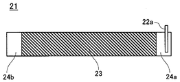
- FIG. 2 is a plan view of the negative electrode plate according to the example.
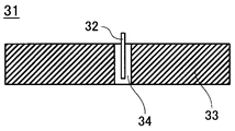
- FIG. 3 is a plan view of the positive electrode plate according to the example.
- FIG. 4 is a perspective view of the electrode body according to the embodiment.
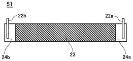
- FIG. 5 is a plan view of a negative electrode plate according to Comparative Example 2 and Comparative Example 3.
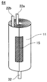
- FIG. 6 is a perspective view of electrode bodies according to Comparative Example 2 and Comparative Example 3.
- Example 1 Preparation of negative electrode active material
- CVD chemical vapor deposition
- the surface of SiO was coated with carbon.
- the coating amount of carbon was 10% by mass with respect to the mass of SiO.
- the SiO particles coated with carbon were subjected to a disproportionation reaction at 1000 ° C. in an argon atmosphere to form a fine Si phase and SiO 2 phase in the SiO particles.
- the obtained particles were classified into a predetermined particle size to obtain SiO as a silicon material.
- This SiO and graphite were mixed so that the mass of SiO was 4% by mass with respect to the mass of SiO and the total mass of graphite to prepare a negative electrode active material.
- a negative electrode active material might be 97 mass parts
- carboxymethylcellulose (CMC) as a thickener might be 1.5 mass parts
- SBR styrene butadiene rubber
- This mixture was put into water as a dispersion medium and kneaded to prepare a negative electrode mixture slurry.
- This negative electrode mixture slurry was applied to both sides of a copper negative electrode current collector having a thickness of 8 ⁇ m by the doctor blade method and dried to form a negative electrode mixture layer 23.
- the first negative electrode current collector exposed portion 24a and the second negative electrode current collector exposed portion 24b in which the negative electrode mixture layer 23 was not formed on both surfaces were provided at positions corresponding to both ends of the completed negative electrode plate 21. . And this negative mix layer 23 was compressed with the roller, and the compressed electrode plate was cut
- a positive electrode current collector exposed portion 34 in which the positive electrode mixture layer 33 was not formed on both surfaces thereof was provided at a position corresponding to the central portion of the completed positive electrode plate 31.
- the positive electrode mixture layer 33 was compressed by a roller, and the compressed electrode plate was cut into a predetermined size.
- an aluminum positive electrode tab 32 was connected to the positive electrode current collector exposed portion 34 to produce a positive electrode plate 31 shown in FIG.
- the negative electrode plate 21 and the positive electrode plate 31 produced as described above were wound through a separator 11 made of a polyethylene microporous film to produce an electrode body 14.
- the first negative electrode current collector exposed portion 24 a was disposed on the winding start side of the electrode body 14, and the second negative electrode current collector exposed portion 24 b was disposed so as to occupy the entire outermost periphery of the electrode body 14.
- a winding tape 15 made of polypropylene having a thickness of 30 ⁇ m was attached to the end of winding of the negative electrode plate 21 as shown in FIG.
- Ethylene carbonate (EC), ethyl methyl carbonate (EMC), and dimethyl carbonate (DMC) were mixed at a volume ratio of 25: 5: 70 (1 atm, 25 ° C.) to prepare a nonaqueous solvent.
- a non-aqueous electrolyte was prepared by dissolving lithium hexafluorophosphate (LiPF 6 ) as an electrolyte salt at a concentration of 1.4 mol / L in this non-aqueous solvent.
- Nonaqueous electrolyte secondary batteries 10 according to Examples 2 to 7 were fabricated in the same manner as in Example 1, except that the content of SiO in the negative electrode active material was changed to the value described in Table 1.
- Example 8 A nonaqueous electrolyte secondary battery 10 according to Example 8 was produced in the same manner as in Example 2 except that silicon (Si) was used instead of SiO coated with carbon.
- Nonaqueous electrolyte secondary batteries 10 according to Examples 9 to 14 were fabricated in the same manner as in Example 8, except that the Si content in the negative electrode active material was changed to the values described in Table 1.
- Example 15 (Production of silicon-graphite composite)
- Si particles are charged into a solvent, methylnaphthalene, together with a bead mill, and the Si particles are wet-pulverized to produce a silicon-containing slurry so that the average particle size (median diameter D50) is 0.2 ⁇ m. did.
- Graphite particles and carbon pitch were added to the silicon-containing slurry and mixed to carbonize the carbon pitch. The product was classified to a predetermined particle size and carbon pitch was added. Further, the carbon pitch was carbonized to obtain a silicon-graphite composite in which Si particles and graphite particles were bound with amorphous carbon. The silicon content in the composite was 20.9% by mass.
- a nonaqueous electrolyte secondary battery 10 according to Example 15 was produced in the same manner as in Example 1 except that the silicon-graphite composite produced as described above was used in place of SiO coated with carbon. .
- Example 16 (Preparation of silicon-lithium silicate composite)
- Si particles and lithium silicate (Li 2 SiO 3 ) particles were mixed at a mass ratio of 42:58, and the mixture was milled with a planetary ball mill.
- the particles milled in an inert gas atmosphere were taken out and heat-treated at 600 ° C. for 4 hours in an inert gas atmosphere.
- Heat-treated particles (hereinafter referred to as mother particles) were pulverized, mixed with coal pitch, and subjected to heat treatment at 800 ° C. for 5 hours in an inert atmosphere to form a carbon conductive layer on the surfaces of the mother particles.
- the amount of carbon contained in the conductive layer was 5% by mass with respect to the total mass of the mother particles and the conductive layer.
- the mother particles were classified to prepare a silicon-lithium silicate composite having an average particle size of 5 ⁇ m.
- a nonaqueous electrolyte secondary battery 10 according to Example 16 was obtained in the same manner as in Example 1 except that the silicon-lithium silicate composite prepared as described above was used in place of SiO coated with carbon. Produced.
- Comparative Example 1 A nonaqueous electrolyte secondary battery according to Comparative Example 1 was produced in the same manner as Example 1 except that only graphite was used as the negative electrode active material.
- Comparative Example 2 Using the negative electrode plate 51 in which the negative electrode tab 22b is connected to the second negative electrode current collector exposed portion 24b, an electrode body 64 whose outermost periphery is covered with the separator 11 is prepared, and the two negative electrode tabs 22a and 22b are attached to the outer can 18.
- a non-aqueous electrolyte secondary battery according to Comparative Example 2 was produced in the same manner as in Example 1 except that it was welded to the bottom of the battery.
- Comparative Example 3 Using the negative electrode plate 51 in which the negative electrode tab 22b is connected to the second negative electrode current collector exposed portion 24b, an electrode body 64 whose outermost periphery is covered with the separator 11 is prepared, and the two negative electrode tabs 22a and 22b are attached to the outer can 18.
- a non-aqueous electrolyte secondary battery according to Comparative Example 3 was produced in the same manner as in Example 11 except that it was welded to the bottom of the battery.
- Example 1 shows that the discharge load characteristic of Example 1 is 99.4%, which is improved as compared with Comparative Example 1.
- the discharge load characteristic of Example 1 is equivalent to that of Comparative Example 2 in which the negative electrode tab is connected to each of the first and second negative electrode current collector exposed portions of the negative electrode plate. This result shows that the energizing function by the contact between the second negative electrode current collector exposed portion and the outer can in Example 1 exhibits the same effect as the energizing function by connecting the negative electrode tab and the outer can. Yes.
- Example 1 It is considered that the above-described effect seen in Example 1 is exhibited by using SiO having a large expansion amount during charging as the negative electrode active material.
- the improvement of the discharge load characteristics indicates that the contact between the negative electrode current collector and the outer can is sufficiently ensured even at the end of discharge when the negative electrode active material contracts.
- the above effect exceeds the expected range because the amount of expansion of the negative electrode active material during charging is large.
- Example 2 and Comparative Example 1 when Example 2 and Comparative Example 1 are compared, it can be seen that the discharge load characteristics are improved even when the content of SiO is 1% by mass. SiO is expected to act to improve the discharge load characteristics even if its content is very small. Therefore, it is not necessary to limit the lower limit of the SiO content. However, if the SiO content is 3% by mass or more, the discharge load characteristics equivalent to those of Comparative Example 2 in which two negative electrode tabs are connected to the negative electrode plate are obtained, and therefore the SiO content is 3% by mass. The above is preferable.
- both the first and second negative electrode current collector exposed portions were provided on both sides of the negative electrode plate.
- the length of the longitudinal direction of the negative electrode plate of a negative electrode collector exposed part can also be made to differ in front and back.
- the negative electrode mixture layer that does not contribute to charge / discharge can be reduced by increasing the inner length of the exposed portion of the first negative electrode current collector.
- the second negative electrode current collector exposed portion may be provided only on the outer side facing the inner wall surface of the outer can.
- the length of the negative electrode plate in the longitudinal direction of the exposed portion of the first negative electrode current collector can be determined within a range in which a region for connecting the negative electrode tab can be secured and the battery capacity is not excessively reduced.
- the length of the exposed portion of the first negative electrode current collector is preferably determined in the range of 3 mm to 30 mm.
- the length of the negative electrode plate in the longitudinal direction of the exposed portion of the second negative electrode current collector can be determined within a range in which sufficient contact with the inner wall surface of the outer can can be secured.
- the length of the exposed portion of the second negative electrode current collector is preferably determined within a range that occupies 30% or more of the outer surface area of the outermost peripheral portion of the negative electrode plate.
- the negative electrode active material silicon material and graphite are used. All of the negative electrode active materials are preferably in the form of particles, and the average particle size thereof is preferably 5 ⁇ m or more and 30 ⁇ m or less.
- the silicon material has lower electronic conductivity than graphite, it is preferable to coat the surface of the silicon material with carbon as shown in the examples.
- the coating amount of carbon is preferably 0.1% by mass or more and 10% by mass or less with respect to the silicon material. However, it is not always essential to coat the surface of the silicon material with carbon, and the effect of the present invention is sufficiently exhibited even when carbon is not coated.
- the mass of carbon covering the surface of the silicon material is not included in the mass of the silicon material.
- the content of the silicon material in the negative electrode active material is not particularly limited, but is preferably 3% by mass or more based on the total mass of the silicon material and graphite. If the content of the silicon material is 3% by mass or more, the load characteristics of the non-aqueous electrolyte secondary battery can be improved, but considering the balance of other battery characteristics such as cycle characteristics, the content of the silicon material is silicon. It is preferably 20% by mass or less, more preferably 10% by mass or less, based on the total mass of the material and graphite.
- Silicon oxide can be used as the silicon material. In consideration of balance with other battery characteristics such as cycle characteristics, it is preferable to use silicon oxide represented by the general formula SiO x (0.5 ⁇ x ⁇ 1.6).
- silicon can be used alone or as a composite with other materials.
- any of single crystal silicon, polycrystalline silicon, and amorphous silicon can be used, but polycrystalline silicon and amorphous silicon having a crystallite size of 60 nm or less are preferable. By using such silicon, cracking of particles during charging and discharging is suppressed, and cycle characteristics are improved.
- the average particle diameter (median diameter D50) of silicon is preferably 0.1 ⁇ m or more and 10 ⁇ m or less, more preferably 0.1 ⁇ m or more and 5 ⁇ m or less.
- Examples of means for obtaining silicon having such an average particle diameter include a dry pulverization method using a jet mill and a ball mill and a wet pulverization method using a bead mill and a ball mill. Silicon can also be alloyed with at least one metal element selected from the group consisting of nickel, copper, cobalt, chromium, iron, silver, titanium, molybdenum, and tungsten.
- a material for forming a composite with silicon it is preferable to use a material having an action of relieving a large volume change caused by charging / discharging of silicon.
- examples of such materials include graphite and lithium silicate.
- silicon particles and graphite particles are bound to each other by amorphous carbon.
- graphite both artificial graphite and natural graphite can be used.
- Pitch-based materials, tar-based materials, and resin-based materials can be used as amorphous carbon precursors that bind silicon particles and graphite particles.
- resin materials include vinyl resins, cellulose resins, and phenol resins. These amorphous carbon precursors can be converted to amorphous carbon by performing a heat treatment at 700 to 1300 ° C. in an inert gas atmosphere.
- the amorphous carbon when amorphous carbon binds silicon particles and graphite particles, the amorphous carbon is included in the constituent elements of the silicon-graphite composite.
- the silicon content in the silicon-graphite composite is preferably 10% by mass or more and 60% by mass or less.
- the silicon-lithium silicate composite preferably has a structure in which silicon particles are dispersed in a lithium silicate phase as shown in Experimental Example 16.
- the silicon content in the silicon-lithium silicate composite is preferably 40% by mass or more and 60% by mass or less.
- SiO x has a structure in which Si particles are dispersed in the SiO 2 phase. This SiO 2 is considered to act so as to relieve the expansion and contraction during the charge and discharge of Si. However, when SiO x is used as the negative electrode active material, SiO 2 reacts with lithium (Li) as shown in formula (1) during charging. 2SiO 2 + 8Li + + 8e over ⁇ Li 4 Si + Li 4 SiO 4 ⁇ (1)
- Li 4 SiO 4 produced by the reaction of SiO 2 and Li cannot reversibly insert and desorb lithium. Therefore, the irreversible capacity accompanying the production of Li 4 SiO 4 is accumulated in the negative electrode containing SiO x as the negative electrode active material during the initial charge. On the other hand, since lithium silicate does not cause a chemical reaction that accumulates irreversible capacity like SiO x , the volume change during charge / discharge of Si can be reduced without reducing the initial charge / discharge efficiency of the negative electrode.
- the lithium silicate is not limited to Li 2 SiO 3 shown in Experimental Example 14, and lithium silicate represented by the general formula Li 2z SiO (2 + z) (0 ⁇ z ⁇ 2) can be used. Moreover, it is preferable that the half width of the diffraction peak of the (111) plane of lithium silicate in the XRD pattern is 0.05 ° or more. Thereby, the lithium ion conductivity in the silicon-lithium silicate composite particles and the effect of mitigating the volume change of Si are further improved.
- both artificial graphite and natural graphite can be used. These can be used alone or in combination.
- any material that can reversibly occlude and release lithium ions can be appropriately selected and used.
- a lithium transition metal composite oxide represented by LiMO 2 (M is at least one of Co, Ni, and Mn), LiMn 2 O 4 , LiFePO 4 , and the like can be used. These can be used alone or in combination of two or more.
- these positive electrode active materials can be used by adding at least one of zirconium, magnesium, aluminum, and titanium or replacing them with a transition metal element.
- a microporous film mainly composed of polyolefin such as polyethylene (PE) or polypropylene (PP) can be used as the separator.
- the microporous membrane can be used singly or as a laminate of two or more layers.
- a layer mainly composed of polyethylene (PE) having a low melting point is used as an intermediate layer and polypropylene (PP) having excellent oxidation resistance is used as a surface layer.
- inorganic particles such as aluminum oxide (Al 2 O 3 ), titanium oxide (TiO 2 ), and silicon oxide (SiO 2 ) can be added to the separator.
- Such inorganic particles can be carried in the separator and can be applied together with a binder on the separator surface.
- An aramid resin can also be applied to the surface of the separator.
- a negative electrode plate is disposed on the outermost periphery of the electrode body.
- the negative electrode plate preferably occupies the entire outermost periphery of the electrode body, but the present invention is not limited to such a configuration.
- a winding tape can be affixed to the end of winding of the negative electrode plate within a range that does not hinder the contact between the exposed portion of the second negative electrode current collector and the inner wall surface of the outer can.
- the range where the winding tape is affixed is determined so that the area where the exposed portion of the second negative electrode current collector and the inner wall surface of the outer can directly face each other is not less than 30% of the outer area of the outermost peripheral portion of the negative electrode plate. Is preferred.
- the thickness of the winding tape can be in a range where the contact between the exposed portion of the second negative electrode current collector and the inner wall surface of the outer can is not hindered.
- the thickness of the winding tape is preferably 50 ⁇ m or less, and more preferably 30 ⁇ m or less.
- non-aqueous electrolyte a solution obtained by dissolving a lithium salt as an electrolyte salt in a non-aqueous solvent can be used.
- a non-aqueous solvent or a non-aqueous electrolyte using a gel polymer together with the non-aqueous solvent can be used.
- a cyclic carbonate ester As the non-aqueous solvent, a cyclic carbonate ester, a chain carbonate ester, a cyclic carboxylic acid ester and a chain carboxylic acid ester can be used, and these are preferably used in combination of two or more.
- the cyclic carbonate include ethylene carbonate (EC), propylene carbonate (PC), and butylene carbonate (BC).
- a cyclic carbonate in which part of hydrogen is substituted with fluorine such as fluoroethylene carbonate (FEC)
- the chain carbonate include dimethyl carbonate (DMC), ethyl methyl carbonate (EMC), diethyl carbonate (DEC), and methyl propyl carbonate (MPC).
- Examples of cyclic carboxylic acid esters include ⁇ -butyrolactone ( ⁇ -BL) and ⁇ -valerolactone ( ⁇ -VL).
- Examples of chain carboxylic acid esters include methyl pivalate, ethyl pivalate, methyl isobutyrate and methyl Pionate is exemplified.
- lithium salts examples include LiPF 6 , LiBF 4 , LiCF 3 SO 3 , LiN (CF 3 SO 2 ) 2 , LiN (C 2 F 5 SO 2 ) 2 , LiN (CF 3 SO 2 ) (C 4 F 9 SO 2 ), LiC (CF 3 SO 2 ) 3 , LiC (C 2 F 5 SO 2 ) 3 , LiAsF 6 , LiClO 4 , Li 2 B 10 Cl 10 and Li 2 B 12 Cl 12 .
- LiPF 6 is particularly preferable, and the concentration in the nonaqueous electrolyte is preferably 0.5 to 2.0 mol / L.
- Other lithium salts such as LiBF 4 may be mixed with LiPF 6 .
- the present invention it is possible to provide a non-aqueous electrolyte secondary battery having a high capacity and excellent output characteristics. Therefore, the industrial applicability of the present invention is great.
Landscapes
- Chemical & Material Sciences (AREA)
- Chemical Kinetics & Catalysis (AREA)
- Electrochemistry (AREA)
- General Chemical & Material Sciences (AREA)
- Engineering & Computer Science (AREA)
- Composite Materials (AREA)
- Materials Engineering (AREA)
- Inorganic Chemistry (AREA)
- Manufacturing & Machinery (AREA)
- Battery Electrode And Active Subsutance (AREA)
- Secondary Cells (AREA)
- Connection Of Batteries Or Terminals (AREA)
Abstract
Description
(負極活物質の作製)
SiO(一般式SiOxのx=1に対応)の組成を有する酸化ケイ素を炭化水素系のガスを含むアルゴン雰囲気下で加熱し、炭化水素系のガスを熱分解させる化学蒸着(CVD)法によりSiOの表面を炭素で被覆した。炭素の被覆量はSiOの質量に対して10質量%とした。次に、炭素で被覆されたSiO粒子をアルゴン雰囲気下、かつ1000℃で不均化反応させることによりSiO粒子中に微細なSi相とSiO2相を形成した。得られた粒子を所定の粒度に分級してケイ素材料としてのSiOを得た。このSiOと黒鉛を、SiOの質量と黒鉛の合計質量に対してSiOの質量が4質量%となるように混合して負極活物質を作製した。
負極活物質が97質量部、増粘剤としてのカルボキシメチルセルロース(CMC)が1.5質量部、結着剤としてのスチレンブタジエンゴム(SBR)が1.5質量部となるように混合した。この混合物を分散媒としての水に投入し、混練して負極合剤スラリーを調製した。この負極合剤スラリーを、厚み8μmの銅製の負極集電体の両面にドクターブレード法により塗布し、乾燥して負極合剤層23を形成した。その際、完成した負極板21の両端に対応する位置にその両面に負極合剤層23が形成されていない第1負極集電体露出部24aと第2負極集電体露出部24bを設けた。そして、この負極合剤層23をローラーにより圧縮し、その圧縮された極板を所定サイズに切断した。最後に、第1負極集電体露出部24aにニッケル製の負極タブ22aを接続して図2に示す負極板21を作製した。
式Ni0.82Co0.15Al0.03O2で表されるニッケル複合酸化物の金属元素の総モル数に対してリチウム元素のモル数が1.025の割合になるように水酸化リチウムを混合した。この混合物を酸素雰囲気下で、750℃で18時間焼成して、LiNi0.82Co0.15Al0.03O2で表されるリチウムニッケル複合酸化物を作製した。
正極活物質としてのLiNi0.82Co0.15Al0.03O2が100質量部、導電剤としてのアセチレンブラックが1質量部、結着剤としてのポリフッ化ビニリデン(PVDF)が0.9質量部となるように混合した。この混合物を分散媒としてのN-メチル-2-ピロリドン(NMP)に投入し、混練して正極合剤スラリーを調製した。この正極合剤スラリーをドクターブレード法により厚み15μmのアルミニウム製の正極集電体の両面に塗布し、乾燥して正極合剤層33を形成した。その際、完成した正極板31の中央部に対応する位置にその両面に正極合剤層33が形成されていない正極集電体露出部34を設けた。この正極合剤層33をローラーにより圧縮し、その圧縮された極板を所定のサイズに切断した。最後に、正極集電体露出部34にアルミニウム製の正極タブ32を接続して図3に示す正極板31を作製した。
上記のようにして作製した負極板21と正極板31をポリエチレン製の微多孔膜からなるセパレータ11を介して巻回して電極体14を作製した。このとき第1負極集電体露出部24aを電極体14の巻始め側に配置し、第2負極集電体露出部24bを電極体14の最外周の全てを占めるように配置した。負極板21の巻終り端部には厚みが30μmのポリプロピレン製の巻留テープ15を図4のように貼り付けた。
エチレンカーボネート(EC)、エチルメチルカーボネート(EMC)、及びジメチルカーボネート(DMC)を25:5:70の体積比(1気圧、25℃)で混合して非水溶媒を調製した。この非水溶媒に電解質塩としてのヘキサフルオロリン酸リチウム(LiPF6)を1.4mol/Lの濃度で溶解して非水電解質を調製した。
電極体14の上下にそれぞれ上部絶縁板12と下部絶縁板13を配置した。次いで、負極タブ22aを電極体14の中心方向へ折り曲げて電極体14を外装缶18へ収納し、負極タブ22aを外装缶18の底部に一対の電極を用いて抵抗溶接により溶接した。正極タブ32は封口体17の端子板に接続した。非水電解質を外装缶18の内部へ注液した後、ガスケット16を介して封口体17を外装缶18の開口部にかしめ固定して、直径18mm、高さ65mmの図1に示す非水電解質二次電池10を作製した。
負極活物質中のSiOの含有量を表1に記載された値に変更したこと以外は実施例1と同様にして実施例2~7に係る非水電解質二次電池10を作製した。
炭素で被覆されたSiOに代えてケイ素(Si)を用いたこと以外は実施例2と同様にして実施例8に係る非水電解質二次電池10を作製した。
負極活物質中のSiの含有量を表1に記載された値に変更したこと以外は実施例8と同様にして実施例9~14に係る非水電解質二次電池10を作製した。
(ケイ素-黒鉛複合体の作製)
窒素ガス雰囲気中で、単結晶のSi粒子をビーズミルとともに溶媒のメチルナフタレンへ投入し、平均粒径(メジアン径D50)が0.2μmになるようにSi粒子を湿式粉砕してケイ素含有スラリーを作製した。そのケイ素含有スラリーに黒鉛粒子と炭素ピッチを加えて混合し、炭素ピッチを炭化させた。その生成物を所定範囲の粒度になるように分級し、炭素ピッチを加えた。さらにその炭素ピッチを炭化させて、Si粒子及び黒鉛粒子が非晶質炭素で結着したケイ素-黒鉛複合体を得た。この複合体中のケイ素の含有量は20.9質量%であった。
(ケイ素-ケイ酸リチウム複合体の作製)
不活性雰囲気中で、Si粒子とケイ酸リチウム(Li2SiO3)粒子を、42:58の質量比で混合し、その混合物を遊星ボールミルでミリング処理を行った。そして不活性ガス雰囲気中でミリング処理した粒子を取り出し、600℃で4時間の熱処理を不活性ガス雰囲気中で行った。熱処理した粒子(以下、母粒子という)を粉砕し、石炭ピッチと混合して800℃で5時間の熱処理を不活性雰囲気中で行って母粒子の表面に炭素の導電層を形成した。導電層に含まれる炭素量は、母粒子及び導電層の合計質量に対して5質量%とした。最後に、母粒子を分級して平均粒径が5μmのケイ素-ケイ酸リチウム複合体を作製した。
ケイ素-ケイ酸リチウム複合体の断面を走査電子顕微鏡(SEM)で観察した結果、複合体中に含まれるSi粒子の平均粒径は100nm未満であった。また、Li2SiO3からなるマトリックス中にSi粒子が均一に分散していることが確認された。ケイ素-ケイ酸リチウム複合体のXRDパターンには、SiとLi2SiO3に帰属される回折ピークが確認された。X線回折(XRD)パターンの2θ=27°付近に現れるLi2SiO3の面指数(111)の半値幅は0.233であった。なお、XRDパターンにSiO2に帰属される回折ピークは確認されず、Si-NMRで測定したSiO2の含有量は検出下限値未満であった。
負極活物質として黒鉛のみを用いたこと以外は実施例1と同様にして比較例1に係る非水電解質二次電池を作製した。
第2負極集電体露出部24bに負極タブ22bを接続した負極板51を用いて最外周がセパレータ11で覆われた電極体64を作製し、2本の負極タブ22a、22bを外装缶18の底部に溶接したこと以外は実施例1と同様にして比較例2に係る非水電解質二次電池を作製した。
第2負極集電体露出部24bに負極タブ22bを接続した負極板51を用いて最外周がセパレータ11で覆われた電極体64を作製し、2本の負極タブ22a、22bを外装缶18の底部に溶接したこと以外は実施例11と同様にして比較例3に係る非水電解質二次電池を作製した。
実施例1~16及び比較例1~3の各電池について、次に述べる条件により放電負荷特性を評価した。まず、各電池を4.2Vになるまで0.5Itの定電流で充電し、電流値が0.02Itになるまで4.2Vの定電圧で充電した。20分の休止後、各電池を電池電圧が2.5Vになるまで0.2Itの定電流で放電して、0.2It放電容量を測定した。次いで、上記の充電方法と同じ条件で各電池を充電した後、各電池を電池電圧が2.5Vになるまで1Itの定電流で放電して、1It放電容量を測定した。0.2It放電容量に対する1It放電容量の百分率を放電負荷特性として算出した。その結果を表1に示す。

2SiO2+8Li++8eー → Li4Si+Li4SiO4 ・・・ (1)
ができる。
11 セパレータ
14 電極体
17 封口体
18 外装缶
21 負極板
22a 負極タブ
23 負極合剤層
24a 第1負極集電体露出部
24b 第2負極集電体露出部
31 正極板
Claims (5)
- 負極板と正極板がセパレータを介して巻回された電極体と、非水電解質と、前記電極体と前記非水電解質を収納する外装缶と、前記外装缶の開口部を封止する封口体とを備え、
前記負極板は負極集電体上に形成された負極合剤層を有し、
前記負極合剤層はケイ素材料及び黒鉛を負極活物質として含み、
前記負極板の巻始め端部に負極タブが接続された第1負極集電体露出部が設けられ、前記負極板の巻終り端部に前記外装缶の内壁面と接触する第2負極集電体露出部が設けられている、
非水電解質二次電池。 - 前記ケイ素材料が、一般式SiOx(0.5≦x<1.6)で表される酸化ケイ素である請求項1記載の非水電解質二次電池。
- 前記ケイ素材料が、ケイ素粒子と黒鉛粒子が非晶質炭素で互いに結着している複合体である請求項1に記載の非水電解質二次電池。
- 前記ケイ素材料が、一般式Li2zSiO(2+z)(0<z<2)で表されるケイ酸リチウム相にケイ素粒子が分散している複合体である請求項1に記載の非水電解質二次電池。
- 前記ケイ素材料の含有量は、前記ケイ素材料と前記黒鉛の合計質量に対して3質量%以上20質量%以下である請求項1から4のいずれかに記載の非水電解質二次電池。
Priority Applications (3)
| Application Number | Priority Date | Filing Date | Title |
|---|---|---|---|
| JP2017506052A JP6652125B2 (ja) | 2015-03-13 | 2016-02-22 | 非水電解質二次電池 |
| CN201680012846.4A CN107431250B (zh) | 2015-03-13 | 2016-02-22 | 非水电解质二次电池 |
| US15/554,076 US20180040881A1 (en) | 2015-03-13 | 2016-02-22 | Non-aqueous electrolyte secondary battery |
Applications Claiming Priority (2)
| Application Number | Priority Date | Filing Date | Title |
|---|---|---|---|
| JP2015050951 | 2015-03-13 | ||
| JP2015-050951 | 2015-03-13 |
Publications (1)
| Publication Number | Publication Date |
|---|---|
| WO2016147564A1 true WO2016147564A1 (ja) | 2016-09-22 |
Family
ID=56918801
Family Applications (1)
| Application Number | Title | Priority Date | Filing Date |
|---|---|---|---|
| PCT/JP2016/000922 Ceased WO2016147564A1 (ja) | 2015-03-13 | 2016-02-22 | 非水電解質二次電池 |
Country Status (4)
| Country | Link |
|---|---|
| US (1) | US20180040881A1 (ja) |
| JP (1) | JP6652125B2 (ja) |
| CN (2) | CN107431250B (ja) |
| WO (1) | WO2016147564A1 (ja) |
Cited By (14)
| Publication number | Priority date | Publication date | Assignee | Title |
|---|---|---|---|---|
| WO2017122251A1 (ja) * | 2016-01-12 | 2017-07-20 | 三洋電機株式会社 | 非水電解質二次電池 |
| WO2018142928A1 (ja) * | 2017-01-31 | 2018-08-09 | パナソニックIpマネジメント株式会社 | 二次電池 |
| WO2019142744A1 (ja) * | 2018-01-19 | 2019-07-25 | 三洋電機株式会社 | 非水電解質二次電池 |
| WO2020084986A1 (ja) * | 2018-10-26 | 2020-04-30 | パナソニックIpマネジメント株式会社 | 円筒型二次電池 |
| CN111183542A (zh) * | 2017-09-29 | 2020-05-19 | 松下电器产业株式会社 | 非水电解质二次电池 |
| JP2020149821A (ja) * | 2019-03-12 | 2020-09-17 | 三洋電機株式会社 | 非水電解質二次電池 |
| WO2021049471A1 (ja) | 2019-09-11 | 2021-03-18 | 三洋電機株式会社 | 非水電解質二次電池 |
| WO2021131257A1 (ja) * | 2019-12-26 | 2021-07-01 | パナソニックIpマネジメント株式会社 | 二次電池用負極活物質および二次電池 |
| JPWO2021153526A1 (ja) * | 2020-01-31 | 2021-08-05 | ||
| JPWO2021200343A1 (ja) * | 2020-03-30 | 2021-10-07 | ||
| US20210399288A1 (en) * | 2018-10-12 | 2021-12-23 | Albemarle Corporation | Particles comprising silicon and lithium |
| WO2025115707A1 (ja) * | 2023-11-30 | 2025-06-05 | パナソニックIpマネジメント株式会社 | 非水電解質二次電池 |
| WO2026048535A1 (ja) * | 2024-08-30 | 2026-03-05 | パナソニックIpマネジメント株式会社 | 円筒形二次電池 |
| WO2026079281A1 (ja) * | 2024-10-07 | 2026-04-16 | パナソニックIpマネジメント株式会社 | 非水電解質二次電池 |
Families Citing this family (14)
| Publication number | Priority date | Publication date | Assignee | Title |
|---|---|---|---|---|
| CN107431250B (zh) * | 2015-03-13 | 2020-08-18 | 三洋电机株式会社 | 非水电解质二次电池 |
| JP7301267B2 (ja) * | 2017-12-28 | 2023-07-03 | パナソニックエナジー株式会社 | 非水電解質二次電池 |
| JPWO2019163392A1 (ja) * | 2018-02-22 | 2021-02-04 | 三洋電機株式会社 | 非水電解質二次電池 |
| WO2019167493A1 (ja) * | 2018-02-28 | 2019-09-06 | パナソニックIpマネジメント株式会社 | 非水電解質二次電池の充電方法、及び非水電解質二次電池の充電システム |
| US12401059B2 (en) * | 2018-03-12 | 2025-08-26 | Tesla, Inc. | Battery systems based on two-additive electrolyte systems including 1,2,6-oxodithiane-2,2,6,6-tetraoxide |
| CN111937187B (zh) * | 2018-04-06 | 2023-04-18 | 三洋电机株式会社 | 圆筒形电池 |
| WO2019207924A1 (ja) * | 2018-04-27 | 2019-10-31 | パナソニックIpマネジメント株式会社 | 非水電解質二次電池 |
| WO2019244818A1 (ja) * | 2018-06-20 | 2019-12-26 | 三洋電機株式会社 | 非水電解質二次電池 |
| JP7157956B2 (ja) * | 2018-11-29 | 2022-10-21 | パナソニックIpマネジメント株式会社 | 円筒型電池及びその製造方法 |
| CN116137936A (zh) * | 2020-07-31 | 2023-05-19 | 三洋电机株式会社 | 非水电解质二次电池 |
| EP4207405A4 (en) * | 2020-08-28 | 2024-11-13 | SANYO Electric Co., Ltd. | Secondary battery |
| KR102900637B1 (ko) * | 2021-02-23 | 2025-12-16 | 주식회사 엘지에너지솔루션 | 고에너지 밀도를 갖는 전극 조립체 및 이를 포함하는 리튬 이차전지 |
| EP4350798A4 (en) * | 2021-05-25 | 2025-04-09 | Panasonic Energy Co., Ltd. | Non-aqueous electrolyte secondary battery |
| CN115528233A (zh) * | 2022-10-13 | 2022-12-27 | 福建蓝海黑石新材料科技有限公司 | 一种预锂化硅基复合负极材料及其制备方法 |
Citations (5)
| Publication number | Priority date | Publication date | Assignee | Title |
|---|---|---|---|---|
| JP2000003722A (ja) * | 1998-06-16 | 2000-01-07 | Fuji Photo Film Co Ltd | 電池及びその製造方法 |
| JP2001110453A (ja) * | 1999-10-04 | 2001-04-20 | Sony Corp | 非水電解液二次電池 |
| JP2002203557A (ja) * | 2000-12-28 | 2002-07-19 | Sony Corp | 非水電解質二次電池 |
| JP2010212228A (ja) * | 2009-02-13 | 2010-09-24 | Hitachi Maxell Ltd | 非水二次電池 |
| JP2014225325A (ja) * | 2011-09-14 | 2014-12-04 | パナソニック株式会社 | 非水電解質二次電池 |
Family Cites Families (23)
| Publication number | Priority date | Publication date | Assignee | Title |
|---|---|---|---|---|
| JPH11120993A (ja) * | 1997-10-17 | 1999-04-30 | Japan Storage Battery Co Ltd | 非水電解質二次電池 |
| JP3724217B2 (ja) * | 1998-08-20 | 2005-12-07 | トヨタ自動車株式会社 | リチウムイオン2次電池用負極 |
| CA2305837C (en) * | 1999-04-14 | 2011-05-31 | Sony Corporation | Material for negative electrode and nonaqueous-electrolyte battery incorporating the same |
| JP3511489B2 (ja) * | 1999-10-14 | 2004-03-29 | 日本碍子株式会社 | リチウム二次電池用捲回型電極体の作製方法 |
| AU7951200A (en) * | 1999-10-22 | 2001-04-30 | Sanyo Electric Co., Ltd. | Electrode for lithium cell and lithium secondary cell |
| JP4137350B2 (ja) * | 2000-06-16 | 2008-08-20 | 三星エスディアイ株式会社 | リチウム二次電池用の負極材料及びリチウム二次電池用の電極及びリチウム二次電池並びにリチウム二次電池用の負極材料の製造方法 |
| JP4385589B2 (ja) * | 2002-11-26 | 2009-12-16 | 昭和電工株式会社 | 負極材料及びそれを用いた二次電池 |
| KR101250329B1 (ko) * | 2002-11-26 | 2013-04-03 | 쇼와 덴코 가부시키가이샤 | 전극 재료, 및 제조방법 및 그 용도 |
| WO2005064714A1 (ja) * | 2003-12-26 | 2005-07-14 | Nec Corporation | 二次電池用負極材料、二次電池用負極およびそれを用いた二次電池 |
| JP5217433B2 (ja) * | 2005-05-16 | 2013-06-19 | 三菱化学株式会社 | 非水電解質二次電池、その負極、及びその材料 |
| KR101375328B1 (ko) * | 2007-07-27 | 2014-03-19 | 삼성에스디아이 주식회사 | Si/C 복합물, 이를 포함하는 음극활물질 및 리튬전지 |
| US20100233524A1 (en) * | 2008-05-28 | 2010-09-16 | Yasuhiko Hina | Cylindrical non-aqueous electrolyte secondary battery |
| KR101042009B1 (ko) * | 2008-09-30 | 2011-06-16 | 한국전기연구원 | 음극 활물질의 제조방법, 그 음극 활물질 및 이를 구비한 리튬이차전지 |
| JP5464653B2 (ja) * | 2009-11-27 | 2014-04-09 | 日立マクセル株式会社 | 非水二次電池およびその製造方法 |
| CN102122708A (zh) * | 2010-01-08 | 2011-07-13 | 中国科学院物理研究所 | 用于锂离子二次电池的负极材料、含该负极材料的负极及其制备方法以及含该负极的电池 |
| JP2013254561A (ja) * | 2010-09-30 | 2013-12-19 | Panasonic Corp | 円筒形非水電解質二次電池 |
| US9520588B2 (en) * | 2011-09-14 | 2016-12-13 | Panasonic Intellectual Property Management Co., Ltd. | Nonaqueous electrolyte secondary cell |
| WO2013054481A1 (ja) * | 2011-10-12 | 2013-04-18 | 株式会社豊田自動織機 | リチウムイオン二次電池、リチウムイオン二次電池用負極及びリチウムイオン二次電池用負極材料 |
| US20130230769A1 (en) * | 2012-02-01 | 2013-09-05 | Electrochemical Materials | Silicon and lithium silicate composite anodes for lithium rechargeable batteries |
| JP5831268B2 (ja) * | 2012-02-07 | 2015-12-09 | 株式会社豊田自動織機 | 二次電池用活物質およびその製造方法 |
| KR101484099B1 (ko) * | 2012-02-08 | 2015-01-19 | 주식회사 엘지화학 | 이차전지 |
| KR101906973B1 (ko) * | 2012-12-05 | 2018-12-07 | 삼성전자주식회사 | 표면 개질된 음극 활물질용 실리콘 나노입자 및 그 제조방법 |
| CN107431250B (zh) * | 2015-03-13 | 2020-08-18 | 三洋电机株式会社 | 非水电解质二次电池 |
-
2016
- 2016-02-22 CN CN201680012846.4A patent/CN107431250B/zh active Active
- 2016-02-22 JP JP2017506052A patent/JP6652125B2/ja active Active
- 2016-02-22 US US15/554,076 patent/US20180040881A1/en not_active Abandoned
- 2016-02-22 WO PCT/JP2016/000922 patent/WO2016147564A1/ja not_active Ceased
- 2016-02-22 CN CN202010701233.XA patent/CN111668473A/zh active Pending
Patent Citations (5)
| Publication number | Priority date | Publication date | Assignee | Title |
|---|---|---|---|---|
| JP2000003722A (ja) * | 1998-06-16 | 2000-01-07 | Fuji Photo Film Co Ltd | 電池及びその製造方法 |
| JP2001110453A (ja) * | 1999-10-04 | 2001-04-20 | Sony Corp | 非水電解液二次電池 |
| JP2002203557A (ja) * | 2000-12-28 | 2002-07-19 | Sony Corp | 非水電解質二次電池 |
| JP2010212228A (ja) * | 2009-02-13 | 2010-09-24 | Hitachi Maxell Ltd | 非水二次電池 |
| JP2014225325A (ja) * | 2011-09-14 | 2014-12-04 | パナソニック株式会社 | 非水電解質二次電池 |
Cited By (29)
| Publication number | Priority date | Publication date | Assignee | Title |
|---|---|---|---|---|
| WO2017122251A1 (ja) * | 2016-01-12 | 2017-07-20 | 三洋電機株式会社 | 非水電解質二次電池 |
| WO2018142928A1 (ja) * | 2017-01-31 | 2018-08-09 | パナソニックIpマネジメント株式会社 | 二次電池 |
| JPWO2018142928A1 (ja) * | 2017-01-31 | 2019-11-14 | パナソニックIpマネジメント株式会社 | 二次電池 |
| CN111183542A (zh) * | 2017-09-29 | 2020-05-19 | 松下电器产业株式会社 | 非水电解质二次电池 |
| CN111183542B (zh) * | 2017-09-29 | 2023-06-02 | 松下控股株式会社 | 非水电解质二次电池 |
| WO2019142744A1 (ja) * | 2018-01-19 | 2019-07-25 | 三洋電機株式会社 | 非水電解質二次電池 |
| JPWO2019142744A1 (ja) * | 2018-01-19 | 2021-01-14 | 三洋電機株式会社 | 非水電解質二次電池 |
| US12087937B2 (en) | 2018-01-19 | 2024-09-10 | Panasonic Energy Co., Ltd. | Non-aqueous electrolyte secondary battery |
| JP7214662B2 (ja) | 2018-01-19 | 2023-01-30 | 三洋電機株式会社 | 非水電解質二次電池 |
| US20210399288A1 (en) * | 2018-10-12 | 2021-12-23 | Albemarle Corporation | Particles comprising silicon and lithium |
| US12368159B2 (en) * | 2018-10-12 | 2025-07-22 | Albemarle Corporation | Particles comprising silicon and lithium |
| US12155041B2 (en) | 2018-10-26 | 2024-11-26 | Panasonic Intellectual Property Management Co., Ltd. | Cylindrical secondary battery |
| JP7320738B2 (ja) | 2018-10-26 | 2023-08-04 | パナソニックIpマネジメント株式会社 | 円筒型二次電池 |
| WO2020084986A1 (ja) * | 2018-10-26 | 2020-04-30 | パナソニックIpマネジメント株式会社 | 円筒型二次電池 |
| JPWO2020084986A1 (ja) * | 2018-10-26 | 2021-09-09 | パナソニックIpマネジメント株式会社 | 円筒型二次電池 |
| JP2020149821A (ja) * | 2019-03-12 | 2020-09-17 | 三洋電機株式会社 | 非水電解質二次電池 |
| JP7317526B2 (ja) | 2019-03-12 | 2023-07-31 | パナソニックエナジー株式会社 | 非水電解質二次電池 |
| WO2021049471A1 (ja) | 2019-09-11 | 2021-03-18 | 三洋電機株式会社 | 非水電解質二次電池 |
| WO2021131257A1 (ja) * | 2019-12-26 | 2021-07-01 | パナソニックIpマネジメント株式会社 | 二次電池用負極活物質および二次電池 |
| JPWO2021153526A1 (ja) * | 2020-01-31 | 2021-08-05 | ||
| WO2021153526A1 (ja) * | 2020-01-31 | 2021-08-05 | パナソニックIpマネジメント株式会社 | 非水電解質二次電池用負極、非水電解質二次電池および非水電解質二次電池用負極の製造方法 |
| JP7611485B2 (ja) | 2020-01-31 | 2025-01-10 | パナソニックIpマネジメント株式会社 | 非水電解質二次電池用負極、非水電解質二次電池および非水電解質二次電池用負極の製造方法 |
| WO2021200343A1 (ja) * | 2020-03-30 | 2021-10-07 | パナソニックIpマネジメント株式会社 | 二次電池 |
| JP7710186B2 (ja) | 2020-03-30 | 2025-07-18 | パナソニックIpマネジメント株式会社 | 二次電池 |
| JPWO2021200343A1 (ja) * | 2020-03-30 | 2021-10-07 | ||
| US12609305B2 (en) | 2020-03-30 | 2026-04-21 | Panasonic Intellectual Property Management Co., Ltd. | Secondary battery |
| WO2025115707A1 (ja) * | 2023-11-30 | 2025-06-05 | パナソニックIpマネジメント株式会社 | 非水電解質二次電池 |
| WO2026048535A1 (ja) * | 2024-08-30 | 2026-03-05 | パナソニックIpマネジメント株式会社 | 円筒形二次電池 |
| WO2026079281A1 (ja) * | 2024-10-07 | 2026-04-16 | パナソニックIpマネジメント株式会社 | 非水電解質二次電池 |
Also Published As
| Publication number | Publication date |
|---|---|
| CN107431250A (zh) | 2017-12-01 |
| JP6652125B2 (ja) | 2020-02-19 |
| US20180040881A1 (en) | 2018-02-08 |
| CN111668473A (zh) | 2020-09-15 |
| JPWO2016147564A1 (ja) | 2017-12-28 |
| CN107431250B (zh) | 2020-08-18 |
Similar Documents
| Publication | Publication Date | Title |
|---|---|---|
| JP6652125B2 (ja) | 非水電解質二次電池 | |
| JP6652121B2 (ja) | 非水電解質二次電池 | |
| JP7063981B2 (ja) | 負極活物質、これを含む負極及びリチウム二次電池 | |
| JP7281570B2 (ja) | 非水電解液二次電池およびその製造方法 | |
| JP5219387B2 (ja) | 非水電解質二次電池 | |
| JP6946536B1 (ja) | リチウム二次電池 | |
| WO2018179817A1 (ja) | 非水電解質二次電池用負極及び非水電解質二次電池 | |
| JPWO2015152113A1 (ja) | 黒鉛系負極活物質材料、負極及びリチウムイオン二次電池 | |
| JP5601536B2 (ja) | 非水電解質二次電池 | |
| WO2015111710A1 (ja) | 非水二次電池 | |
| JP7556779B2 (ja) | 負極活物質、負極、及び二次電池 | |
| JP6697377B2 (ja) | リチウムイオン二次電池 | |
| JP6448462B2 (ja) | 非水電解質二次電池用負極活物質及び非水電解質二次電池並びに非水電解質二次電池用負極活物質の製造方法 | |
| JP2018523279A (ja) | 二次電池用正極、この製造方法及びこれを含むリチウム二次電池 | |
| JPWO2012144177A1 (ja) | リチウムイオン二次電池用負極及びその負極を用いたリチウムイオン二次電池 | |
| WO2016136226A1 (ja) | 非水電解質二次電池の製造方法 | |
| KR20130119956A (ko) | 비수 이차 전지 | |
| JP5505479B2 (ja) | リチウムイオン二次電池用負極及びその負極を用いたリチウムイオン二次電池 | |
| CN103299459A (zh) | 制备负极活性材料的方法 | |
| JP7214662B2 (ja) | 非水電解質二次電池 | |
| JPWO2014068931A1 (ja) | 非水電解質二次電池 | |
| WO2015083262A1 (ja) | リチウムイオン二次電池用負極材料及びその製造方法、リチウムイオン二次電池用負極及びその製造方法並びにリチウムイオン二次電池 | |
| JPWO2015025887A1 (ja) | リチウムイオン二次電池用負極およびリチウムイオン二次電池 | |
| JP6922373B2 (ja) | 非水電解質蓄電素子用負極活物質、非水電解質蓄電素子用負極、及び非水電解質蓄電素子 | |
| JP2014116217A (ja) | リチウムイオン二次電池用正極及びリチウムイオン二次電池 |
Legal Events
| Date | Code | Title | Description |
|---|---|---|---|
| 121 | Ep: the epo has been informed by wipo that ep was designated in this application |
Ref document number: 16764397 Country of ref document: EP Kind code of ref document: A1 |
|
| WWE | Wipo information: entry into national phase |
Ref document number: 15554076 Country of ref document: US |
|
| ENP | Entry into the national phase |
Ref document number: 2017506052 Country of ref document: JP Kind code of ref document: A |
|
| NENP | Non-entry into the national phase |
Ref country code: DE |
|
| 122 | Ep: pct application non-entry in european phase |
Ref document number: 16764397 Country of ref document: EP Kind code of ref document: A1 |