WO2016010031A1 - 偏光フィルムおよびその製造方法 - Google Patents
偏光フィルムおよびその製造方法 Download PDFInfo
- Publication number
- WO2016010031A1 WO2016010031A1 PCT/JP2015/070141 JP2015070141W WO2016010031A1 WO 2016010031 A1 WO2016010031 A1 WO 2016010031A1 JP 2015070141 W JP2015070141 W JP 2015070141W WO 2016010031 A1 WO2016010031 A1 WO 2016010031A1
- Authority
- WO
- WIPO (PCT)
- Prior art keywords
- active energy
- energy ray
- polarizing film
- adhesive composition
- meth
- Prior art date
Links
- 0 *c(cc12)cc(*)c1Sc(cccc1)c1C2=O Chemical compound *c(cc12)cc(*)c1Sc(cccc1)c1C2=O 0.000 description 1
Images
Classifications
-
- G—PHYSICS
- G02—OPTICS
- G02B—OPTICAL ELEMENTS, SYSTEMS OR APPARATUS
- G02B5/00—Optical elements other than lenses
- G02B5/30—Polarising elements
-
- C—CHEMISTRY; METALLURGY
- C09—DYES; PAINTS; POLISHES; NATURAL RESINS; ADHESIVES; COMPOSITIONS NOT OTHERWISE PROVIDED FOR; APPLICATIONS OF MATERIALS NOT OTHERWISE PROVIDED FOR
- C09J—ADHESIVES; NON-MECHANICAL ASPECTS OF ADHESIVE PROCESSES IN GENERAL; ADHESIVE PROCESSES NOT PROVIDED FOR ELSEWHERE; USE OF MATERIALS AS ADHESIVES
- C09J11/00—Features of adhesives not provided for in group C09J9/00, e.g. additives
- C09J11/02—Non-macromolecular additives
- C09J11/06—Non-macromolecular additives organic
-
- C—CHEMISTRY; METALLURGY
- C09—DYES; PAINTS; POLISHES; NATURAL RESINS; ADHESIVES; COMPOSITIONS NOT OTHERWISE PROVIDED FOR; APPLICATIONS OF MATERIALS NOT OTHERWISE PROVIDED FOR
- C09J—ADHESIVES; NON-MECHANICAL ASPECTS OF ADHESIVE PROCESSES IN GENERAL; ADHESIVE PROCESSES NOT PROVIDED FOR ELSEWHERE; USE OF MATERIALS AS ADHESIVES
- C09J11/00—Features of adhesives not provided for in group C09J9/00, e.g. additives
- C09J11/08—Macromolecular additives
-
- C—CHEMISTRY; METALLURGY
- C09—DYES; PAINTS; POLISHES; NATURAL RESINS; ADHESIVES; COMPOSITIONS NOT OTHERWISE PROVIDED FOR; APPLICATIONS OF MATERIALS NOT OTHERWISE PROVIDED FOR
- C09J—ADHESIVES; NON-MECHANICAL ASPECTS OF ADHESIVE PROCESSES IN GENERAL; ADHESIVE PROCESSES NOT PROVIDED FOR ELSEWHERE; USE OF MATERIALS AS ADHESIVES
- C09J133/00—Adhesives based on homopolymers or copolymers of compounds having one or more unsaturated aliphatic radicals, each having only one carbon-to-carbon double bond, and at least one being terminated by only one carboxyl radical, or of salts, anhydrides, esters, amides, imides, or nitriles thereof; Adhesives based on derivatives of such polymers
-
- C—CHEMISTRY; METALLURGY
- C09—DYES; PAINTS; POLISHES; NATURAL RESINS; ADHESIVES; COMPOSITIONS NOT OTHERWISE PROVIDED FOR; APPLICATIONS OF MATERIALS NOT OTHERWISE PROVIDED FOR
- C09J—ADHESIVES; NON-MECHANICAL ASPECTS OF ADHESIVE PROCESSES IN GENERAL; ADHESIVE PROCESSES NOT PROVIDED FOR ELSEWHERE; USE OF MATERIALS AS ADHESIVES
- C09J5/00—Adhesive processes in general; Adhesive processes not provided for elsewhere, e.g. relating to primers
-
- G—PHYSICS
- G02—OPTICS
- G02B—OPTICAL ELEMENTS, SYSTEMS OR APPARATUS
- G02B1/00—Optical elements characterised by the material of which they are made; Optical coatings for optical elements
- G02B1/10—Optical coatings produced by application to, or surface treatment of, optical elements
- G02B1/14—Protective coatings, e.g. hard coatings
-
- G—PHYSICS
- G02—OPTICS
- G02F—OPTICAL DEVICES OR ARRANGEMENTS FOR THE CONTROL OF LIGHT BY MODIFICATION OF THE OPTICAL PROPERTIES OF THE MEDIA OF THE ELEMENTS INVOLVED THEREIN; NON-LINEAR OPTICS; FREQUENCY-CHANGING OF LIGHT; OPTICAL LOGIC ELEMENTS; OPTICAL ANALOGUE/DIGITAL CONVERTERS
- G02F1/00—Devices or arrangements for the control of the intensity, colour, phase, polarisation or direction of light arriving from an independent light source, e.g. switching, gating or modulating; Non-linear optics
- G02F1/01—Devices or arrangements for the control of the intensity, colour, phase, polarisation or direction of light arriving from an independent light source, e.g. switching, gating or modulating; Non-linear optics for the control of the intensity, phase, polarisation or colour
- G02F1/13—Devices or arrangements for the control of the intensity, colour, phase, polarisation or direction of light arriving from an independent light source, e.g. switching, gating or modulating; Non-linear optics for the control of the intensity, phase, polarisation or colour based on liquid crystals, e.g. single liquid crystal display cells
- G02F1/133—Constructional arrangements; Operation of liquid crystal cells; Circuit arrangements
- G02F1/1333—Constructional arrangements; Manufacturing methods
- G02F1/1335—Structural association of cells with optical devices, e.g. polarisers or reflectors
Definitions
- the present invention relates to a polarizing film in which a transparent protective film is laminated on at least one surface of a polarizer via an adhesive layer and a method for producing the same.
- the polarizing film can form an image display device such as a liquid crystal display device (LCD), an organic EL display device, a CRT, or a PDP alone or as an optical film obtained by laminating the polarizing film.
- Liquid crystal display devices are rapidly expanding in the market for watches, mobile phones, PDAs, notebook computers, personal computer monitors, DVD players, TVs, etc.
- the liquid crystal display device visualizes the polarization state by switching of the liquid crystal, and a polarizer is used from the display principle.
- polarizing films are also required to have higher transmittance, higher degree of polarization, and higher color reproducibility.
- an iodine-based polarizer having a stretched structure by adsorbing iodine to polyvinyl alcohol (hereinafter also simply referred to as “PVA”) is most widely used. in use.
- PVA polyvinyl alcohol
- a polarizing film in which a transparent protective film is bonded to both surfaces of a polarizer by a so-called aqueous adhesive in which a polyvinyl alcohol-based material is dissolved in water is used (Patent Document 1 and Patent Document 2 below).
- the transparent protective film triacetyl cellulose having a high moisture permeability is used. When the water-based adhesive is used (so-called wet lamination), a drying process is required after the polarizer and the transparent protective film are bonded together.
- an active energy ray-curable adhesive has been proposed.
- an active energy ray-curable adhesive has been proposed.
- the present inventors have proposed radical polymerization type active energy ray-curable adhesives using N-substituted amide monomers as curable components (Patent Documents 3 and 4 below).
- JP 2006-220732 A JP 2001-296427 A JP2012-052000A JP 2012-068593 A
- the adhesive layer formed using the active energy ray-curable adhesive described in Patent Documents 3 and 4 is, for example, a water resistance test for evaluating the presence or absence of color loss or peeling after immersion in warm water at 60 ° C. for 6 hours. It is clear enough. However, in recent years, for the adhesive for polarizing films, for example, it is possible to clear the more severe water resistance test that evaluates the presence or absence of peeling when the edge nail peeling is performed after being immersed (saturated) in water. Further improvement in water resistance is being demanded. Therefore, the actual situation is that there is room for further improvement in terms of water resistance for the adhesives for polarizing films reported up to now, including the active energy ray-curable adhesives described in Patent Documents 3 and 4. there were.
- the organic polymer material is often required to have a trade-off characteristic, and it is difficult for a single organic polymer material to satisfy the required property.
- techniques for adding and compounding different kinds of materials having different properties to organic polymer materials have been proposed in many fields.
- the bonding technique for example, when two different types of adherends are bonded, it is conceivable to form the adhesive layer so as to have a two-layer structure in order to improve the adhesion to each adherend.
- stress concentrates on the interface, and the adhesive force of the adhesive layer may be reduced.
- a polarizing film having an adhesive layer exhibiting high adhesive force when laminating a polarizer and a transparent protective film and having excellent water resistance, and production thereof It aims to provide a method.
- the polarizer and the transparent protective film which are members of the polarizing film, exhibit different properties also from the viewpoint of hydrophilicity, and thus forming an adhesive layer for laminating these adherends in a two-layer structure, although it is advantageous from the viewpoint of improving the adhesive strength between the two adherends, as described above, there is a risk of lowering the adhesive strength due to interfacial peeling in the adhesive layer.
- the inventors of the present invention do not use a two-layer structure of the adhesive layer, but a component gradient that increases the concentration of the hydrophilic component on the polarizer side in the adhesive layer. It has been found that by having the structure, the water resistance of the adhesive layer can be improved while improving the adhesion to the polarizer.
- the present invention has been completed based on this discovery, and has the following configuration.
- the present invention is a polarizing film in which a transparent protective film is laminated on at least one surface of a polarizer via an adhesive layer, and the adhesive layer is active in an active energy ray-curable adhesive composition.
- the active energy ray-curable adhesive composition is formed of a cured product layer obtained by irradiating energy rays. And a B component having a log Pow of 2 to 7, and the adhesive layer has a high concentration of the A component on the polarizer side.
- the adhesive layer provided in the polarizing film according to the present invention is formed of a cured product layer obtained by irradiating an active energy ray curable adhesive composition with an active energy ray, and the active energy ray curable adhesive composition.
- a cured product layer obtained by irradiating an active energy ray curable adhesive composition with an active energy ray, and the active energy ray curable adhesive composition.
- the polarizer, particularly the polyvinyl alcohol polarizer, which is the adherend of the adhesive layer shows hydrophilicity, but the adhesive layer according to the present invention has a high concentration of the A component on the polarizer side, and the A component is The logPow is ⁇ 1 to 1, indicating high hydrophilicity.
- the adhesive layer provided in the polarizing film according to the present invention has a component gradient structure that increases the concentration of the A component on the polarizer side, it is transparent while the concentration of the A component on the polarizer side is high.
- logPow is 2 to 7, and the concentration of the B component exhibiting high hydrophobicity is high. Since the transparent protective film is more hydrophobic than the polarizer, the adhesive layer provided in the polarizing film according to the present invention strongly adheres to the transparent protective film and improves water resistance.
- TOF-SIMS Time of Flight Secondary Ion Mass Spectrometry
- the principle of TOF-SIMS is that when a sample is irradiated with a primary ion beam (for example, 1E12 ions / cm 2 or less) under an ultra-high vacuum, secondary ions are emitted only from the outermost surface of the sample (a depth of about several millimeters).
- a mass spectrum is obtained by introducing secondary ions into a time-of-flight (TOF type) mass spectrometer.
- TOF type time-of-flight
- the adhesive layer has a component gradient structure that increases the concentration of the A component on the polarizer side and further increases the concentration of the A component on the polarizer side. Therefore, a cluster ion etching method can be used.
- the “cluster ion etching method” will be described below.
- a general etching method using a monoatomic ion beam (Ar + , Cs +, etc.) as etching ions the molecular structure on the surface of the adhesive layer is destroyed, A damage layer is formed.
- the accurate mass spectrum of the surface of the adhesive layer cannot be measured due to the influence of the damaged layer.
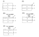
- FIG. 1 is a schematic diagram showing a method for evaluating the point where the concentration of the A component on the polarizer side is increased in the adhesive layer using TOF-SIMS.
- (I) of FIG. 1 shows an example of a polarizing film according to the present invention.
- a transparent protective film 2 is laminated on both surfaces of a polarizer 1 via an adhesive layer 3.
- the transparent protective film 2 of the polarizing film shown in (I) (the upper transparent protective film 2 in FIG. 1 (I)) is horizontally cut with a microtome to reduce the thickness of the transparent protective film 2 in contact with the adhesive layer 3. ((II)).
- the composition of the surface is analyzed by measuring the mass spectrum of the surface of the thin transparent protective film 2 using TOF-SIMS.
- the surface of the transparent protective film 2 that has been thinly cut is etched using the “cluster ion etching method”, and then the composition of the surface is analyzed using TOF-SIMS.
- the surface of the transparent protective film 2 is deposited by etching the surface of the transparent protective film 2 using the “cluster ion etching method”, and TOF-SIMS is deposited. Is used to analyze the composition of the surface.
- the etching process using the “cluster ion etching method” and the analysis of the composition of the surface of the deposited adhesive layer 3 are repeated using TOF-SIMS, and etching is performed until it finally reaches the polarizer surface. Processing and analysis of the composition of the surface of the adhesive layer 3 (and the polarizer 1) are continued. Confirmed that the adhesive layer has a component gradient structure that increases the concentration of the A component on the polarizer side and further increases the concentration of the A component on the polarizer side by the method described above. can do.
- the active energy ray-curable adhesive composition contains a (meth) acrylamide derivative as the component A
- the active energy ray-curable adhesive composition is more likely to be used as the component B.
- it contains a functional (meth) acrylate the adhesiveness of the adhesive layer to the polarizer and the transparent protective film and the water resistance are further increased, which is preferable.
- the active energy ray-curable adhesive composition contains an acrylic oligomer obtained by polymerizing a (meth) acrylic monomer.
- the active energy ray-curable adhesive composition preferably contains a hydroxyl group-containing photopolymerization initiator.
- the active energy ray-curable adhesive composition contains an acrylic oligomer obtained by polymerizing a non-polymerizable (meth) acrylic monomer, the component of the adhesive composition interposed between the polarizer and the transparent protective film The uneven distribution tends to proceed, and the concentration of the component A tends to be higher on the polarizer side in the adhesive layer.
- concentration of A component by the side of a polarizer increases, and the sclerosis
- the adhesiveness of the adhesive layer to the polarizer and the transparent protective film and the water resistance are further enhanced, which is preferable.
- the active energy ray-curable adhesive composition contains at least one organometallic compound selected from the group consisting of metal alkoxides and metal chelates.
- the active energy ray-curable adhesive composition contains at least one organometallic compound selected from the group consisting of metal alkoxides and metal chelates, such organometallic compounds becomes an active metal species due to the presence of moisture, and as a result, the organometallic compound strongly interacts with both the polarizer and the active energy ray-curable component constituting the adhesive layer.
- the organometallic compound strongly interacts with both the polarizer and the active energy ray-curable component constituting the adhesive layer.
- the adhesive water resistance between the polarizer and the adhesive layer Will improve dramatically.
- the metal of the organometallic compound contained in the active energy ray-curable adhesive composition is titanium.
- the active energy ray-curable adhesive composition preferably contains the metal alkoxide as the organometallic compound, and the metal alkoxide has 6 or more carbon atoms.
- the active energy ray-curable adhesive composition contains the metal chelate as the organometallic compound, and the number of carbon atoms of the organic group of the metal chelate is 4 or more.
- the polarizing film preferably contains an alkoxysilane group-containing compound having a viscosity of 15 mPa ⁇ s or more.
- the active energy ray-curable adhesive composition forming the adhesive layer contains an alkoxysilane group-containing compound having a viscosity of 15 mPa ⁇ s or more
- the adhesive water resistance between the polarizer and the adhesive layer is The following points can be considered as reasons for improvement.
- moisture permeates through the protective film and moisture diffuses into the adhesive layer the alkoxysilane group of the compound becomes a silanol group at the interface between the polarizer and the adhesive layer, resulting in the presence of moisture on the surface of the polarizer.
- the adhesive property is maintained in the pre-polymerization stage of the adhesive composition, and is being polymerized during the polymerization stage of the composition.
- the agent composition and the alkoxysilane group-containing compound are moderately incompatible, and tend to be more unevenly distributed at the adherend interface than the low-viscosity (low molecular weight) alkoxysilane group-containing compound.
- an alkoxysilane group-containing compound having a viscosity of 15 mPa ⁇ s or more is unevenly distributed on the polarizer surface side. Hydrogen bonds and / or ionic bonds, as well as covalent bonds, are formed, and the water resistance of adhesion between the polarizer and the adhesive layer is dramatically improved.
- the main chain of the alkoxysilane group-containing compound preferably has an acrylic polymer structure.
- the storage modulus at 25 ° C. of the adhesive layer obtained by curing the active energy ray-curable adhesive composition is preferably 1.0 ⁇ 10 7 Pa or more.
- the polarizing film according to the present invention includes, for example, a coating step of applying the active energy ray-curable adhesive composition to at least one surface of the polarizer and the transparent protective film, and the polarizer and the transparent It was obtained by curing the active energy ray-curable adhesive composition by irradiating active energy rays from the polarizer surface side or the transparent protective film surface side, and a bonding step of bonding a protective film. It can manufacture by the manufacturing method including the adhesion
- the concentration of the component A is preferred because it tends to be higher on the polarizer side.
- the temperature of the active energy ray-curable adhesive composition is adjusted. It can also be adjusted by adjusting the temperature of the film to be applied.
- the polarizing film according to the present invention is characterized in that the adhesive layer formed after the bonding step has a high concentration of the component A on the polarizer side.
- the polarizing film according to the present invention is, for example, the following production method; A method for producing a polarizing film comprising a transparent protective film laminated on at least one surface of a polarizer via an adhesive layer, wherein the adhesive layer is applied to an active energy ray-curable adhesive composition. Is formed by a cured product layer obtained by irradiating with a first activity containing an A component having a logPow of ⁇ 1 to 1 representing an octanol / water partition coefficient on the bonding surface of the polarizer.
- the adhesive layer can also be produced by a method for producing a polarizing film, wherein the concentration of the component A on the polarizer side is high.
- the adhesive layer when the adhesive layer is formed in a two-layer structure, stress concentrates on the interface and the adhesive force of the adhesive layer may be reduced.
- the manufacturing method since the first active energy ray-curable adhesive composition and the second active energy ray-curable adhesive composition are bonded together in a fluid state, a certain amount between the two layers. Since compatibilization proceeds, a two-layer structure is not formed, and a component gradient structure is formed on the polarizer side so that the concentration of the A component exhibiting high hydrophilicity is increased. Therefore, interface peeling between the first active energy ray-curable adhesive composition and the second active energy ray-curable adhesive composition does not occur, and the polarizer and the transparent protective film have good adhesiveness, The polarizing film has good water resistance.
- the active energy ray-curable adhesive composition contains at least one organometallic compound selected from the group consisting of metal alkoxides and metal chelates.
- the first active energy ray-curable adhesive composition contains the organometallic compound.
- the metal of the organometallic compound contained in the active energy ray-curable adhesive composition is titanium.
- the said active energy ray hardening-type adhesive composition contains the said metal alkoxide as said organometallic compound, and carbon number of the organic group which the said metal alkoxide has is 6 or more.
- the said active energy ray hardening-type adhesive composition contains the said metal chelate as said organometallic compound, and carbon number of the organic group which the said metal chelate has is 4 or more.
- an alkoxysilane group-containing compound having a viscosity of 15 mPa ⁇ s or more is preferably contained.
- the main chain of the alkoxysilane group-containing compound preferably has an acrylic polymer structure.
- curing the said active energy ray hardening-type adhesive composition is 1.0 * 10 ⁇ 7 > Pa or more.
- the polarizing film according to the present invention is obtained by laminating a transparent protective film on at least one surface of a polarizer via an adhesive layer, and the adhesive layer is active in an active energy ray-curable adhesive composition. It is formed by a cured product layer obtained by irradiating energy rays.
- Active energy ray curable adhesive compositions can be broadly classified into electron beam curable, ultraviolet curable, visible light curable, and the like. Furthermore, ultraviolet curable and visible light curable adhesives can be classified into radical polymerization curable adhesives and cationic polymerization adhesives. In the present invention, an active energy ray having a wavelength range of 10 nm to less than 380 nm is expressed as ultraviolet light, and an active energy ray having a wavelength range of 380 nm to 800 nm is expressed as visible light.
- Examples of the compound constituting the radical polymerization curable adhesive include radical polymerizable compounds.
- Examples of the radical polymerizable compound include compounds having a radical polymerizable functional group of a carbon-carbon double bond such as a (meth) acryloyl group and a vinyl group.
- these curable components either a monofunctional radical polymerizable compound or a bifunctional or higher polyfunctional radical polymerizable compound can be used.
- these radically polymerizable compounds can be used individually by 1 type or in combination of 2 or more types.
- compounds having a (meth) acryloyl group are suitable.
- the active energy ray-curable adhesive composition used in the present invention preferably contains a compound having a (meth) acryloyl group as a main component. Specifically, the total amount of the active energy ray-curable adhesive composition is When the content is 100% by weight, the compound having a (meth) acryloyl group is preferably contained in an amount of 50% by weight or more, and more preferably 80% by weight or more.
- (meth) acryloyl means an acryloyl group and / or methacryloyl group, and “(meth)” has the same meaning hereinafter.
- Examples of the monofunctional radical polymerizable compound include (meth) acrylamide derivatives having a (meth) acrylamide group.
- a (meth) acrylamide derivative is preferable in terms of securing adhesiveness with a polarizer and various transparent protective films, and having a high polymerization rate and excellent productivity.
- (meth) acrylamide derivatives include, for example, N-methyl (meth) acrylamide, N, N-dimethyl (meth) acrylamide, N, N-diethyl (meth) acrylamide, N-isopropyl (meth) acrylamide, N N-alkyl group-containing (meth) acrylamide derivatives such as butyl (meth) acrylamide and N-hexyl (meth) acrylamide; N-methylol (meth) acrylamide, N-hydroxyethyl (meth) acrylamide, N-methylol-N— N-hydroxyalkyl group-containing (meth) acrylamide derivatives such as propane (meth) acrylamide; N-aminoalkyl group-containing (meth) acrylamide derivatives such as aminomethyl (meth) acrylamide and aminoethyl (meth) acrylamide; N-methoxymethyl N-alkoxy group-containing (meth) acrylamide derivatives such as
- heterocyclic-containing (meth) acrylamide derivative in which the nitrogen atom of the (meth) acrylamide group forms a heterocyclic ring examples include, for example, N-acryloylmorpholine, N-acryloylpiperidine, N-methacryloylpiperidine, N-acryloylpyrrolidine. Etc.
- N-hydroxyalkyl group-containing (meth) acrylamide derivatives are preferred from the viewpoint of adhesion to polarizers and various transparent protective films, and monofunctional radically polymerizable compounds are also preferred.
- Examples include various (meth) acrylic acid derivatives having a (meth) acryloyloxy group.
- Examples of the (meth) acrylic acid derivative include cycloalkyl (meth) acrylates such as cyclohexyl (meth) acrylate and cyclopentyl (meth) acrylate; aralkyl (meth) acrylates such as benzyl (meth) acrylate; 2-isobornyl (Meth) acrylate, 2-norbornylmethyl (meth) acrylate, 5-norbornen-2-yl-methyl (meth) acrylate, 3-methyl-2-norbornylmethyl (meth) acrylate, dicyclopentenyl (meth) ) Polycyclic (meth) acrylates such as acrylate, dicyclopentenyloxyethyl (meth) acrylate, dicyclopentanyl (meth) acrylate, 2-methoxyethyl (meth) acrylate, 2-ethoxy Ethyl (meth) acrylate, -Methoxymethoxyethyl (me
- Examples of the (meth) acrylic acid derivative include 2-hydroxyethyl (meth) acrylate, 2-hydroxypropyl (meth) acrylate, 3-hydroxypropyl (meth) acrylate, 2-hydroxybutyl (meth) acrylate, 4- Hydroxyalkyl (meth) acrylates such as hydroxybutyl (meth) acrylate, 6-hydroxyhexyl (meth) acrylate, 8-hydroxyoctyl (meth) acrylate, 10-hydroxydecyl (meth) acrylate, 12-hydroxylauryl (meth) acrylate, etc.
- hydroxyl groups such as [4- (hydroxymethyl) cyclohexyl] methyl acrylate, cyclohexanedimethanol mono (meth) acrylate, 2-hydroxy-3-phenoxypropyl (meth) acrylate, etc.
- (Meth) acrylate glycidyl (meth) acrylate, epoxy group-containing (meth) acrylate such as 4-hydroxybutyl (meth) acrylate glycidyl ether; 2,2,2-trifluoroethyl (meth) acrylate, 2,2,2 -Trifluoroethylethyl (meth) acrylate, tetrafluoropropyl (meth) acrylate, hexafluoropropyl (meth) acrylate, octafluoropentyl (meth) acrylate, heptadecafluorodecyl (meth) acrylate, 3-chloro-2-hydroxy Halogen-containing (meth) acrylates such as propyl (meth) acrylate; alkylaminoalkyl (meth) acrylates such as dimethylaminoethyl (meth) acrylate; 3-oxetanylmethyl (meth) acrylate
- examples of the monofunctional radically polymerizable compound include carboxyl group-containing monomers such as (meth) acrylic acid, carboxyethyl acrylate, carboxypentyl acrylate, itaconic acid, maleic acid, fumaric acid, crotonic acid, and isocrotonic acid.
- carboxyl group-containing monomers such as (meth) acrylic acid, carboxyethyl acrylate, carboxypentyl acrylate, itaconic acid, maleic acid, fumaric acid, crotonic acid, and isocrotonic acid.
- Examples of the monofunctional radical polymerizable compound include lactam vinyl monomers such as N-vinyl pyrrolidone, N-vinyl- ⁇ -caprolactam, and methyl vinyl pyrrolidone; vinyl pyridine, vinyl piperidone, vinyl pyrimidine, vinyl piperazine, vinyl pyrazine, Examples thereof include vinyl monomers having a nitrogen-containing heterocyclic ring such as vinyl pyrrole, vinyl imidazole, vinyl oxazole and vinyl morpholine.
- lactam vinyl monomers such as N-vinyl pyrrolidone, N-vinyl- ⁇ -caprolactam, and methyl vinyl pyrrolidone
- vinyl pyridine vinyl piperidone
- vinyl pyrimidine vinyl piperazine
- vinyl pyrazine examples thereof include vinyl monomers having a nitrogen-containing heterocyclic ring such as vinyl pyrrole, vinyl imidazole, vinyl oxazole and vinyl morpholine.
- a radically polymerizable compound having an active methylene group can be used as the monofunctional radically polymerizable compound.
- the radical polymerizable compound having an active methylene group is a compound having an active methylene group having an active double bond group such as a (meth) acryl group at the terminal or in the molecule.
- the active methylene group include an acetoacetyl group, an alkoxymalonyl group, and a cyanoacetyl group.
- the active methylene group is preferably an acetoacetyl group.
- radical polymerizable compound having an active methylene group examples include 2-acetoacetoxyethyl (meth) acrylate, 2-acetoacetoxypropyl (meth) acrylate, 2-acetoacetoxy-1-methylethyl (meth) acrylate, and the like.
- Examples include acrylamide, N- (4-acetoacetoxymethylbenzyl) acrylamide, and N- (2-acetoacetylaminoethyl) acrylamide.
- the radical polymerizable compound having an active methylene group is preferably acetoacetoxyalkyl (meth) acrylate.
- Examples of the bifunctional or higher polyfunctional radical polymerizable compound include tripropylene glycol di (meth) acrylate, tetraethylene glycol di (meth) acrylate, 1,6-hexanediol di (meth) acrylate, 1,9 -Nonanediol di (meth) acrylate, 1,10-decanediol diacrylate, 2-ethyl-2-butylpropanediol di (meth) acrylate, bisphenol A di (meth) acrylate, bisphenol A ethylene oxide adduct di (meth) ) Acrylate, bisphenol A propylene oxide adduct di (meth) acrylate, bisphenol A diglycidyl ether di (meth) acrylate, neopentyl glycol di (meth) acrylate, tricyclodecane dimethanol di (meth) Acryte, cyclic trimethylol
- Aronix M-220 manufactured by Toagosei Co., Ltd.
- light acrylate 1,9ND-A manufactured by Kyoeisha Chemical Co., Ltd.
- light acrylate DGE-4A manufactured by Kyoeisha Chemical Co., Ltd.
- light acrylate DCP-A manufactured by Sartomer
- SR-531 manufactured by Sartomer
- CD-536 manufactured by Sartomer
- various epoxy (meth) acrylates, urethane (meth) acrylates, polyester (meth) acrylates, various (meth) acrylate monomers, and the like are included as necessary.
- the adhesive layer according to the present invention has a high concentration of component A on the polarizer side.
- the active energy ray-curable adhesive composition includes an A component having a logPow representing an octanol / water partition coefficient of ⁇ 1 to 1, and a logPow And B component which is 2-7.
- Octanol / water partition coefficient is an index representing the lipophilicity of a substance, and means a logarithmic value of the partition coefficient of octanol / water.
- High logPow means that it is lipophilic, that is, low water absorption.
- the logPow value can be measured (flask immersion method described in JIS-Z-7260), but can also be calculated. In this specification, the logPow value calculated by Chem Draw Ultra manufactured by Cambridge Soft is used.
- a compound having a log Pow of ⁇ 1 to 1 can be arbitrarily used.
- hydroxyethylacrylamide Product name "HEAA”, manufactured by Kojin Co., Ltd., LogPow; -0.56
- N-vinylformamide product name "Beamset 770", manufactured by Arakawa Chemical Co., Ltd., LogPow; -0.25
- acryloylmorpholine product
- ACMO acryloylmorpholine
- GBLA manufactured by Osaka Organic Chemical Industry Co., Ltd., LogPow; 0.19
- acrylic acid dimer trade name
- ⁇ -CEA manufactured by Daicel, LogPow; 0.2
- N-vinylpyrrolidone trade name “NVP”, manufactured by Nippo
- a (meth) acrylamide derivative is preferably used as the component A having a log Pow of ⁇ 1 to 1, and further, hydroxyethylacrylamide, acryloylmorpholine, or dimethylacrylamide is preferably used.
- hydroxyethylacrylamide, acryloylmorpholine, or dimethylacrylamide is preferably used.
- 4-hydroxybutyl acrylate is preferably used.
- the content of the component A having a log Pow of ⁇ 1 to 1 is 5 to 50% by weight is preferable, and 10 to 45% by weight is more preferable.
- a compound having a log Pow of 2 to 7 can be arbitrarily used.
- dicyclopentenyl acrylate- (Trade name “Fancryl FA-511AS”, manufactured by Hitachi Chemical Co., Ltd., LogPow; 2.26), butyl acrylate (trade name “butyl acrylate”, manufactured by Mitsubishi Chemical Corporation, LogPow; 2.35), 1, 6-hexanediol diacrylate (trade name “Light acrylate 1.6HX-A”, manufactured by Kyoeisha Chemical Co., Ltd., LogPow; 2.43), dicyclopentanyl acrylate (trade name “Fancryl FA-513AS”, Hitachi Chemical Co., Ltd., LogPow; 2.58), dimethylol-tricyclodecane diacrylate (trade name “Light Acrylate D”) “PA”, manufactured by Kyoeisha Chemical Co., Ltd
- a polyfunctional (meth) acrylate as the B component having a log Pow of 2 to 7, more preferably 1,6-hexanediol diacrylate), dimethylol-tricyclodecanedi.
- the content of the B component having a log Pow of 2 to 7 is: It is preferably 30 to 95% by weight, and more preferably 40 to 80% by weight.
- an active energy ray-curable adhesive composition uses an electron beam or the like as an active energy ray
- the active energy ray-curable adhesive composition does not need to contain a photopolymerization initiator.
- ultraviolet rays or visible rays are used for the energy rays, it is preferable to contain a photopolymerization initiator.
- the photopolymerization initiator in the case of using the radical polymerizable compound is appropriately selected depending on the active energy ray.
- a photopolymerization initiator for ultraviolet light or visible light cleavage is used.
- photopolymerization initiator examples include benzophenone compounds such as benzyl, benzophenone, benzoylbenzoic acid, 3,3′-dimethyl-4-methoxybenzophenone; 4- (2-hydroxyethoxy) phenyl (2-hydroxy-2 -Propyl) ketone, aromatic ketone compounds such as ⁇ -hydroxy- ⁇ , ⁇ '-dimethylacetophenone, 2-methyl-2-hydroxypropiophenone, ⁇ -hydroxycyclohexyl phenyl ketone; methoxyacetophenone, 2,2-dimethoxy- Acetophenone compounds such as 2-phenylacetophenone, 2,2-diethoxyacetophenone, 2-methyl-1- [4- (methylthio) -phenyl] -2-morpholinopropane-1; benzoin methyl ether; Benzoin ethyl ether, benzoin Benzoin ether compounds such as isopropyl ether, benzoin butyl ether and ani
- the blending amount of the photopolymerization initiator is 20% by weight or less when the total amount of the active energy ray-curable adhesive composition is 100% by weight.
- the blending amount of the photopolymerization initiator is preferably 0.01 to 20% by weight, more preferably 0.05 to 10% by weight, and further preferably 0.1 to 5% by weight.
- a photopolymerization initiator that is particularly sensitive to light of 380 nm or more is used. It is preferable to use it.
- a photopolymerization initiator that is highly sensitive to light of 380 nm or more will be described later.
- R 1 and R 2 represent —H, —CH 2 CH 3 , —iPr or Cl, and R 1 and R 2 may be the same or different), respectively, or a general formula ( It is preferable to use together the compound represented by 1) and a photopolymerization initiator that is highly sensitive to light of 380 nm or more, which will be described later.
- the adhesiveness is excellent as compared with a case where a photopolymerization initiator having high sensitivity to light of 380 nm or more is used alone.
- diethylthioxanthone in which R 1 and R 2 are —CH 2 CH 3 is particularly preferable.
- composition ratio of the compound represented by the general formula (1) in the adhesive composition is preferably 0.1 to 5 parts by weight with respect to 100 parts by weight of the total amount of the curable component, 0.5 to The amount is more preferably 4 parts by weight, still more preferably 0.9 to 3 parts by weight.
- polymerization initiators include triethylamine, diethylamine, N-methyldiethanolamine, ethanolamine, 4-dimethylaminobenzoic acid, methyl 4-dimethylaminobenzoate, ethyl 4-dimethylaminobenzoate, isoamyl 4-dimethylaminobenzoate, etc. Among them, ethyl 4-dimethylaminobenzoate is particularly preferable.
- a polymerization initiation assistant When a polymerization initiation assistant is used, its addition amount is usually 0 to 5 parts by weight, preferably 0 to 4 parts by weight, most preferably 0 to 3 parts by weight, based on 100 parts by weight of the total amount of the curable component. is there.
- a known photopolymerization initiator can be used in combination as necessary. Since the transparent protective film having UV absorbing ability does not transmit light of 380 nm or less, it is preferable to use a photopolymerization initiator that is highly sensitive to light of 380 nm or more as the photopolymerization initiator.
- 2-methyl-1- (4-methylthiophenyl) -2-morpholinopropan-1-one 2-benzyl-2-dimethylamino-1- (4-morpholinophenyl) -butanone-1 2- (dimethylamino) -2-[(4-methylphenyl) methyl] -1- [4- (4-morpholinyl) phenyl] -1-butanone, 2,4,6-trimethylbenzoyl-diphenyl-phosphine Oxide, bis (2,4,6-trimethylbenzoyl) -phenylphosphine oxide, bis ( ⁇ 5-2,4-cyclopentadien-1-yl) -bis (2,6-difluoro-3- (1H-pyrrole) 1-yl) -phenyl) titanium and the like.
- R 3 , R 4 and R 5 represent —H, —CH 3 , —CH 2 CH 3 , —iPr or Cl, and R 3 , R 4 and R 5 may be the same or different. It is preferable to use it.
- R 3 , R 4 and R 5 represent —H, —CH 3 , —CH 2 CH 3 , —iPr or Cl, and R 3 , R 4 and R 5 may be the same or different. It is preferable to use it.
- the compound represented by the general formula (2) 2-methyl-1- (4-methylthiophenyl) -2-morpholinopropan-1-one (trade name: IRGACURE907 manufacturer: BASF) which is also a commercial product is suitable. Can be used.
- 2-benzyl-2-dimethylamino-1- (4-morpholinophenyl) -butanone-1 (trade name: IRGACURE369 manufacturer: BASF)
- 2- (dimethylamino) -2-[(4-methylphenyl) Methyl] -1- [4- (4-morpholinyl) phenyl] -1-butanone (trade name: IRGACURE379 manufacturer: BASF) is preferred because of its high sensitivity.
- the active energy ray-curable adhesive composition contains a hydroxyl group-containing photopolymerization initiator as a polymerization initiator, the solubility in the adhesive layer having a high concentration of the component A on the polarizer side is increased, and the adhesive layer The curability of is increased.
- the photopolymerization initiator having a hydroxyl group include 2-methyl-2-hydroxypropiophenone (trade name “DAROCUR1173”, manufactured by BASF), 1-hydroxycyclohexyl phenyl ketone (trade name “IRGACURE184”, manufactured by BASF).
- 1- [4- (2-hydroxyethoxy) -phenyl] -2-hydroxy-2-methyl-1-propan-1-one (trade name “IRGACURE2959”, manufactured by BASF)
- 2-hydroxy-1- Examples include ⁇ 4- [4- (2-hydroxy-2-methyl-propionyl) -benzyl] phenyl ⁇ -2-methyl-propan-1-one (trade name “IRGACURE127”, manufactured by BASF).
- 1-hydroxycyclohexyl phenyl ketone is more preferable because it has particularly excellent solubility in an adhesive layer having a high concentration of component A.
- a radical polymerizable compound having an active methylene group when used as the radical polymerizable compound, it is preferably used in combination with a radical polymerization initiator having a hydrogen abstracting action. According to such a configuration, the adhesiveness of the adhesive layer of the polarizing film is remarkably improved even in a high humidity environment or immediately after being taken out from water (non-dried state). The reason for this is not clear, but the following causes are considered.
- the radical polymerizable compound having an active methylene group is taken into the main chain and / or side chain of the base polymer in the adhesive layer while polymerizing together with other radical polymerizable compounds constituting the adhesive layer.
- An agent layer is formed.
- a radical polymerization initiator having a hydrogen abstracting action is present, a base polymer constituting the adhesive layer is formed, while hydrogen is extracted from the radical polymerizable compound having an active methylene group to form a methylene group. Radicals are generated. And the methylene group which the radical generate
- the adhesiveness of the adhesive layer of the polarizing film is remarkably improved even in a non-dry state.
- examples of the radical polymerization initiator having a hydrogen abstracting action include thioxanthone radical polymerization initiators and benzophenone radical polymerization initiators.
- the radical polymerization initiator is preferably a thioxanthone radical polymerization initiator.
- examples of the thioxanthone radical polymerization initiator include compounds represented by the above general formula (1).
- Specific examples of the compound represented by the general formula (1) include thioxanthone, dimethylthioxanthone, diethylthioxanthone, isopropylthioxanthone, and chlorothioxanthone.
- diethylthioxanthone in which R 1 and R 2 are —CH 2 CH 3 is particularly preferable.
- the total amount of the curable component is 100% by weight.
- a radical is generated in the methylene group of a radical polymerizable compound having an active methylene group in the presence of a radical polymerization initiator having a hydrogen abstraction function, and the methylene group and a polarizer such as PVA are used. React with a hydroxyl group to form a covalent bond. Therefore, in order to generate radicals in the methylene group of the radical polymerizable compound having an active methylene group and to sufficiently form such a covalent bond, when the total amount of the curable component is 100% by weight, the radical having an active methylene group.
- the content of the polymerizable compound is preferably 1 to 50% by weight, and more preferably 3 to 30% by weight.
- the radical polymerizable compound having an active methylene group is preferably 1% by weight or more. On the other hand, if it exceeds 50% by weight, the adhesive layer may be poorly cured.
- the radical polymerization initiator having a hydrogen abstracting action is preferably contained in an amount of 0.1 to 10 parts by weight, more preferably 0.3 to 9 parts by weight, based on 100 parts by weight of the total amount of the curable component. More preferred. In order for the hydrogen abstraction reaction to proceed sufficiently, it is preferable to use 0.1 parts by weight or more of a radical polymerization initiator. On the other hand, if it exceeds 10 parts by weight, it may not completely dissolve in the composition.
- the curable component of the cationic polymerization curable adhesive examples include compounds having an epoxy group or an oxetanyl group.
- the compound having an epoxy group is not particularly limited as long as it has at least two epoxy groups in the molecule, and various generally known curable epoxy compounds can be used.
- a preferable epoxy compound a compound having at least two epoxy groups and at least one aromatic ring in the molecule (aromatic epoxy compound), or at least two epoxy groups in the molecule, at least one of them. Examples thereof include a compound (alicyclic epoxy compound) formed between two adjacent carbon atoms constituting an alicyclic ring.
- the active energy ray-curable adhesive composition has an octanol / water partition coefficient even in the case where a cationic polymerization curable adhesive is used to realize a component gradient structure in the adhesive layer in the adhesive layer. It is necessary to contain an A component having a logPow of ⁇ 1 to 1 and a B component having a logPow of 2 to 7.
- the cationic polymerization curable adhesive contains the epoxy compound and the oxetane compound described above as curable components, and these are cured by cationic polymerization, and therefore, a photocationic polymerization initiator is blended therein.
- This cationic photopolymerization initiator generates a cationic species or a Lewis acid by irradiation with active energy rays such as visible light, ultraviolet rays, X-rays, and electron beams, and starts a polymerization reaction of an epoxy group or an oxetanyl group.
- a metal alkoxide is a compound in which at least one alkoxy group, which is an organic group, is bonded to a metal
- a metal chelate is a compound in which an organic group is bonded or coordinated to the metal via an oxygen atom.
- Titanium, aluminum, and zirconium are preferable as the metal. Among these, compared with titanium, aluminum and zirconium are fast in reactivity, the pot life of the adhesive composition is shortened, and the effect of improving the adhesion water resistance may be lowered. Therefore, titanium is more preferable as the metal of the organometallic compound from the viewpoint of improving the adhesive water resistance of the adhesive layer.
- the curable adhesive composition for a polarizing film according to the present invention contains a metal alkoxide as the organometallic compound, it is preferable to use a metal alkoxide having an organic group having 4 or more carbon atoms, It is more preferable to contain a thing.
- the carbon number is 3 or less, the pot life of the adhesive composition may be shortened, and the effect of improving the adhesion water resistance may be reduced.
- the organic group having 6 or more carbon atoms include an octoxy group, which can be suitably used.
- suitable metal alkoxides include, for example, tetraisopropyl titanate, tetranormal butyl titanate, butyl titanate dimer, tetraoctyl titanate, tertiary amyl titanate, tetra tertiary butyl titanate, tetrastearyl titanate, zirconium tetraisopropoxide, zirconium Tetranormal butoxide, zirconium tetraoctoxide, zirconium tetratertiary butoxide, zirconium tetrapropoxide, aluminum sec butyrate, aluminum ethylate, aluminum isopropylate, aluminum butyrate, aluminum diisopropylate monosecondary butyrate, monosec butoxyaluminum And diisopropylate. Of these, tetraoctyl titanate is preferable.
- the organic chelate preferably has an organic group having 4 or more carbon atoms.
- the carbon number is 3 or less, the pot life of the adhesive composition may be shortened, and the effect of improving the adhesion water resistance may be reduced.
- the organic group having 4 or more carbon atoms include acetylacetonate group, ethylacetoacetate group, isostearate group, octylene glycolate group and the like. Among these, from the viewpoint of improving the adhesive water resistance of the adhesive layer, an acetylacetonate group or an ethylacetoacetate group is preferable as the organic group.
- suitable metal chelates include, for example, titanium acetylacetonate, titanium octylene glycolate, titanium tetraacetylacetonate, titanium ethylacetoacetate, polyhydroxytitanium stearate, dipropoxy-bis (acetylacetonato) titanium, di Butoxytitanium-bis (octylene glycolate), dipropoxytitanium-bis (ethylacetoacetate), titanium lactate, titanium diethanolamate, titanium triethanolamate, dipropoxytitanium-bis (lactate), dipropoxytitanium-bis ( Triethanolaminate), di-n-butoxytitanium-bis (triethanolaminato), tri-n-butoxytitanium monostearate, diisopropoxy bis (ethylacetoacetate) Titanium, diisopropoxy bis (acetylacetate) titanium, diisopropoxy bis (acetylacetone) titanium, titanium phosphate compound, titanium lactate
- the organic metal compounds usable in the present invention include organic carboxylic acid metal salts such as zinc octylate, zinc laurate, zinc stearate, tin octylate, acetylacetone zinc chelate, benzoylacetone zinc chelate, dibenzoylmethane zinc
- the chelate include zinc chelate compounds such as ethyl zinc acetoacetate chelate.
- the active energy ray-curable adhesive composition according to the present invention may contain the following components.
- alkoxysilane group-containing compound having a viscosity of 15 mPa ⁇ s or more As an alkoxysilane group-containing compound having a viscosity of 15 mPa ⁇ s or more, a compound having a higher molecular weight than a low molecular weight compound containing an alkoxysilane group is used, and in particular, an alkoxysilane group is contained in a side chain and / or a molecular terminal.
- the polymer or oligomer type alkoxysilane group-containing compound can be suitably used.
- the polymer containing an alkoxysilane group at the side chain and / or molecular end those having a (meth) acrylic polymer structure as the main chain can be suitably used.
- the (meth) acrylic monomer constituting the acrylic polymer include (meth) acrylic acid; methyl (meth) acrylate, ethyl (meth) acrylate, n-propyl (meth) acrylate, and (meth) acrylic.
- the viscosity of the polymer containing an alkoxysilane group at the side chain and / or molecular end is 15 mPa ⁇ s or more, more preferably 10,000 mPa ⁇ s or more, and still more preferably 100,000 mPa ⁇ s or more.
- the upper limit of the viscosity is not particularly limited, but is preferably 2000000 mPa ⁇ s or less in consideration of workability and the like.
- Examples of the oligomer type alkoxysilane group-containing compound include hydrolysis condensates of low molecular weight alkoxysilane group-containing compounds. Commercially available products can also be suitably used as the hydrolysis condensate of the low molecular weight alkoxysilane group-containing compound. For example, X-41-1059A, X-24-9590, KR-516, X manufactured by Shin-Etsu Chemical Co., Ltd.
- the viscosity of the oligomer type alkoxysilane group-containing compound is 15 mPa ⁇ s or more, more preferably 20 mPa ⁇ s or more, and further preferably 25 mPa ⁇ s or more.
- the upper limit of the viscosity is not particularly limited, but is preferably 100,000 mPa ⁇ s or less in consideration of workability and the like.
- the content of the alkoxysilane group-containing compound having a viscosity of 15 mPa ⁇ s or more is preferably in the range of 0.2 to 15 parts by weight with respect to 100 parts by weight of the total amount of the active energy ray-curable component.
- the amount is preferably 5 to 10 parts by weight, and more preferably 0.8 to 5 parts by weight.
- the storage stability of the adhesive composition may be deteriorated, or the ratio of components for adhering to a polarizer or a protective film may be relatively insufficient, resulting in a decrease in adhesiveness.
- the amount is less than 0.2 parts by weight, the effect of adhesion water resistance is not sufficiently exhibited.
- the active energy ray-curable adhesive composition used in the present invention is an acrylic composition obtained by polymerizing a (meth) acrylic monomer in addition to the curable component of the radical polymerizable compound or the cationic polymerization curable adhesive.
- An oligomer can be contained.
- the active energy ray-curable adhesive composition contains an acrylic oligomer obtained by polymerizing a non-polymerizable (meth) acrylic monomer, the component of the adhesive composition interposed between the polarizer and the transparent protective film The uneven distribution easily proceeds, and a component gradient structure in which the concentration of the A component on the polarizer side becomes high can be obtained more easily.
- the total amount of the active energy ray-curable adhesive composition was set to 100% by weight.
- the content of the acrylic oligomer is preferably 5 to 30% by weight, more preferably 10 to 20% by weight.
- the active energy ray-curable adhesive composition preferably has a low viscosity in consideration of workability and uniformity during coating. Therefore, an acrylic oligomer (A) obtained by polymerizing a (meth) acrylic monomer. It is also preferable that the viscosity is low.
- the acrylic oligomer having a low viscosity preferably has a weight average molecular weight (Mw) of 15000 or less, more preferably 10,000 or less, and particularly preferably 5000 or less.
- the weight average molecular weight (Mw) of the acrylic oligomer (A) is preferably 500 or more, It is more preferably 1000 or more, and particularly preferably 1500 or more.
- the (meth) acrylic monomer constituting the acrylic oligomer (A) include methyl (meth) acrylate, ethyl (meth) acrylate, n-propyl (meth) acrylate, isopropyl (meth) acrylate, 2 -Methyl-2-nitropropyl (meth) acrylate, n-butyl (meth) acrylate, isobutyl (meth) acrylate, S-butyl (meth) acrylate, t-butyl (meth) acrylate, n-pentyl (meth) acrylate, t-pentyl (meth) acrylate, 3-pentyl (meth) acrylate, 2,2-dimethylbutyl (meth) acrylate, n-hexyl (meth) acrylate, cetyl (meth) acrylate, n-octyl (meth) acrylate, 2 -Ethy
- acrylic oligomer (A) examples include “ARUFON” manufactured by Toagosei Co., Ltd., “Act Flow” manufactured by Soken Chemical Co., Ltd., “JONCRYL” manufactured by BASF Japan.
- the acrylic oligomer (A) When the acrylic oligomer (A) is a liquid, it is preferably used because it is not necessary to consider the solubility in the adhesive composition.
- the acrylic oligomer (A) is usually a liquid when the glass transition temperature (Tg) is less than 25 ° C.
- the acrylic oligomer (A) preferably contains a polar functional group. Examples of the polar functional group include a hydroxyl group, an epoxy group, a carboxyl group, and an alkoxysilyl group.
- Specific examples include “ARUFON UH series”, “ARUFON UC series”, “ARUFON UF series”, “ARUFON UG series”, “ARUFON US series” (all manufactured by Toagosei Co., Ltd.). Especially, since the adhesive improvement by interaction with a polarizer is anticipated, it is preferable to contain an epoxy group. Specific examples include “ARUFON UG-4000” and “ARUFON UG-4010” (both manufactured by Toagosei Co., Ltd.).
- the active energy ray-curable adhesive composition can contain a photoacid generator.
- the active energy ray-curable resin composition contains a photoacid generator, the water resistance and durability of the adhesive layer can be dramatically improved as compared with the case where no photoacid generator is contained.
- the photoacid generator can be represented by the following general formula (3).
- L + represents an arbitrary onium cation.
- X ⁇ represents PF6 6 ⁇ , SbF. It represents a counter anion selected from the group consisting of 6 ⁇ , AsF 6 ⁇ , SbCl 6 ⁇ , BiCl 5 ⁇ , SnCl 6 ⁇ , ClO 4 ⁇ , dithiocarbamate anion, and SCN—.
- PF 6 -, SbF 6 - and AsF 6 - and the like particularly preferable ones as the general formula (3) in counter anion X- is, PF 6 -, SbF 6 - and AsF 6 - and the like, particularly preferably, PF 6 -, SbF 6 - and the like.
- preferred onium salts constituting the photoacid generator that can be used in the present invention include “Syracure UVI-6922” and “Syracure UVI-6974” (above, manufactured by Dow Chemical Japan Co., Ltd.).
- “Adekaoptomer SP150”, “Adekaoptomer SP152”, “Adekaoptomer SP170”, “Adekaoptomer SP172” (manufactured by ADEKA Corporation), “IRGACURE250” (manufactured by Ciba Specialty Chemicals), “ “CI-5102”, “CI-2855” (manufactured by Nippon Soda Co., Ltd.), “Sun-Aid SI-60L”, “Sun-Aid SI-80L”, “Sun-Aid SI-100L”, “Sun-Aid SI-110L”, “Sun-Aid SI” -180L “(Sanshin Chemical Co., Ltd.),” CPI-10 “ “P”, “CPI-100A” (manufactured by San Apro Co., Ltd.), “WPI-069”, “WPI-113”, “WPI-116”, “WPI-041”, “WPI-044”, “WPI-” “054”, “WPI-
- the content of the photoacid generator is 10 parts by weight or less, preferably 0.01 to 10 parts by weight, and preferably 0.05 to 5 parts by weight with respect to 100 parts by weight of the total amount of the curable component. More preferred is 0.1 to 3 parts by weight.
- a compound containing either alkoxy group or epoxy group in the active energy ray-curable adhesive composition, a compound containing a photoacid generator and either an alkoxy group or an epoxy group can be used in combination.
- Compound having epoxy group and polymer When using a compound having one or more epoxy groups in the molecule or a polymer (epoxy resin) having two or more epoxy groups in the molecule, two functional groups having reactivity with the epoxy group are contained in the molecule. Two or more compounds may be used in combination.
- the functional group having reactivity with an epoxy group include a carboxyl group, a phenolic hydroxyl group, a mercapto group, a primary or secondary aromatic amino group, and the like. It is particularly preferable to have two or more of these functional groups in one molecule in consideration of three-dimensional curability.
- Examples of the polymer having one or more epoxy groups in the molecule include epoxy resins, bisphenol A type epoxy resins derived from bisphenol A and epichlorohydrin, bisphenol F type epoxy derived from bisphenol F and epichlorohydrin.
- Resin bisphenol S type epoxy resin, phenol novolak type epoxy resin, cresol novolak type epoxy resin, bisphenol A novolak type epoxy resin, bisphenol F novolak type epoxy resin, alicyclic epoxy resin, diphenyl ether type epoxy resin, hydroquinone type epoxy resin, Multifunctional epoxy resin such as naphthalene type epoxy resin, biphenyl type epoxy resin, fluorene type epoxy resin, trifunctional type epoxy resin and tetrafunctional type epoxy resin There are glycidyl ester type epoxy resins, glycidyl amine type epoxy resins, hydantoin type epoxy resins, isocyanurate type epoxy resins, aliphatic chain epoxy resins, etc.
- epoxy resins may be halogenated and hydrogenated. May be.
- resin products for example, JER Coat 828, 1001, 801N, 806, 807, 152, 604, 630, 871, YX8000, YX8034, YX4000 manufactured by Japan Epoxy Resin Co., Ltd., Epicron manufactured by DIC Corporation 830, EXA835LV, HP4032D, HP820, EP4100 series, EP4000 series, EPU series, manufactured by ADEKA Co., Ltd., Celoxide series (2021, 2021P, 2083, 2085, 3000, etc.) manufactured by Daicel Chemical Industries, Ltd., Eporide series, EHPE Series, YD series, YDF series, YDCN series, YDB series, phenoxy resin (polyethylene synthesized from bisphenols and epichlorohydrin) B carboxymethyl having an epoxy group at both ends with polyether; YP series, etc.), Nagase Chemt
- the compound having an alkoxyl group in the molecule is not particularly limited as long as it has one or more alkoxyl groups in the molecule, and known compounds can be used. Representative examples of such compounds include melamine compounds, amino resins, and silane coupling agents.
- the compounding amount of the compound containing either an alkoxy group or an epoxy group is usually 30 parts by weight or less with respect to 100 parts by weight of the total amount of the curable component, and if the content of the compound in the composition is too large, May deteriorate and impact resistance against drop test may deteriorate.
- the content of the compound in the composition is more preferably 20 parts by weight or less.
- the compound preferably contains 2 parts by weight or more, more preferably 5 parts by weight or more in the composition.
- polarizing film curable adhesive of the present invention is an active energy ray-curable curable adhesive
- silane coupling agents include vinyltrichlorosilane, vinyltrimethoxysilane, vinyltriethoxysilane, 2- (3,4 epoxycyclohexyl) ethyltrimethoxysilane, and 3-glycid as active energy ray-curable compounds.
- Xylpropyltrimethoxysilane 3-glycidoxypropylmethyldiethoxysilane, 3-glycidoxypropyltriethoxysilane, p-styryltrimethoxysilane, 3-methacryloxypropylmethyldimethoxysilane, 3-methacryloxypropyltrimethoxy Examples thereof include silane, 3-methacryloxypropylmethyldiethoxysilane, 3-methacryloxypropyltriethoxysilane, and 3-acryloxypropyltrimethoxysilane.
- a silane coupling agent (D1) having an amino group is preferable.
- the silane coupling agent (D1) having an amino group include ⁇ -aminopropyltrimethoxysilane, ⁇ -aminopropyltriethoxysilane, ⁇ -aminopropyltriisopropoxysilane, ⁇ -aminopropylmethyldimethoxysilane, ⁇ -aminopropylmethyldiethoxysilane, ⁇ - (2-aminoethyl) aminopropyltrimethoxysilane, ⁇ - (2-aminoethyl) aminopropylmethyldimethoxysilane, ⁇ - (2-aminoethyl) aminopropyltriethoxysilane ⁇ - (2-aminoethyl) aminopropylmethyldiethoxysilane, ⁇ - (2-aminoeth
- the silane coupling agent (D1) having an amino group may be used alone or in combination of two or more.
- the blending amount of the silane coupling agent is preferably in the range of 0.01 to 20 parts by weight, preferably 0.05 to 15 parts by weight, with respect to 100 parts by weight of the total amount of the curable component. More preferably, it is 10 parts by weight. This is because when the blending amount exceeds 20 parts by weight, the storage stability of the adhesive deteriorates, and when the blending amount is less than 0.1 part by weight, the water-resistant adhesive effect is not sufficiently exhibited.
- silane coupling agents that are not active energy ray-curable other than the above include 3-ureidopropyltriethoxysilane, 3-chloropropyltrimethoxysilane, 3-mercaptopropylmethyldimethoxysilane, 3-mercaptopropyltrimethoxy.
- Examples include silane, bis (triethoxysilylpropyl) tetrasulfide, 3-isocyanatopropyltriethoxysilane, and imidazolesilane.
- the curable adhesive composition for polarizing films of the present invention contains a compound having a vinyl ether group
- the adhesive water resistance between the polarizer and the adhesive layer is improved, which is preferable.
- the reason why such an effect is obtained is not clear, but one of the reasons is that the adhesive force between the polarizer and the adhesive layer is increased by the interaction of the vinyl ether group of the compound having a vinyl ether group with the polarizer. Presumed to be.
- the compound having a vinyl ether group is preferably a radical polymerizable compound having a vinyl ether group.
- the content of the compound having a vinyl ether group is preferably 0.1 to 19 parts by weight with respect to 100 parts by weight of the total amount of the curable component.
- the curable adhesive composition for polarizing film of the present invention may contain a compound that causes keto-enol tautomerism.
- a compound that causes keto-enol tautomerism for example, in an adhesive composition containing a cross-linking agent or an adhesive composition that can be used by blending a cross-linking agent, an embodiment containing a compound that produces the keto-enol tautomerism can be preferably employed.
- an adhesive composition containing a cross-linking agent or an adhesive composition that can be used by blending a cross-linking agent an embodiment containing a compound that produces the keto-enol tautomerism can be preferably employed.
- the excessive viscosity rise and gelation of the adhesive composition after the compounding of the organometallic compound and the formation of a microgel product can be suppressed, and the effect of extending the pot life of the composition can be realized.
- ⁇ -dicarbonyl compounds can be used as the compound that causes keto-enol tautomerism.
- Specific examples include acetylacetone, 2,4-hexanedione, 3,5-heptanedione, 2-methylhexane-3,5-dione, 6-methylheptane-2,4-dione, 2,6-dimethylheptane- ⁇ -diketones such as 3,5-dione; acetoacetates such as methyl acetoacetate, ethyl acetoacetate, isopropyl acetoacetate, tert-butyl acetoacetate; ethyl propionyl acetate, ethyl propionyl acetate, isopropyl propionyl acetate, propionyl acetate propionyl acetates such as tert-butyl; isobutyryl acetates such as ethyl isobutyryl acetate
- the amount of the compound that generates keto-enol tautomerism is, for example, 0.05 to 10 parts by weight, preferably 0.2 to 3 parts by weight (for example, 0.3 parts by weight) with respect to 1 part by weight of the organometallic compound. Parts by weight to 2 parts by weight). If the amount of the compound used is less than 0.05 parts by weight relative to 1 part by weight of the organometallic compound, it may be difficult to achieve a sufficient use effect. On the other hand, when the amount of the compound used exceeds 10 parts by weight with respect to 1 part by weight of the organometallic compound, it may be difficult to express the desired water resistance due to excessive interaction with the organometallic compound.
- additives can be mix
- additives include epoxy resin, polyamide, polyamideimide, polyurethane, polybutadiene, polychloroprene, polyether, polyester, styrene-butadiene block copolymer, petroleum resin, xylene resin, ketone resin, cellulose resin, fluorine-based oligomer, Polymers or oligomers such as silicone oligomers and polysulfide oligomers; polymerization inhibitors such as phenothiazine and 2,6-di-t-butyl-4-methylphenol; polymerization initiators; leveling agents; wettability improvers; Plasticizers; UV absorbers; inorganic fillers; pigments; dyes and the like.
- the above additives are usually 0 to 10 parts by weight, preferably 0 to 5 parts by weight, and most preferably 0 to 3 parts by weight with respect to 100 parts by weight of the total amount of the curable component.
- the active energy ray-curable adhesive composition used in the present invention contains the curable component, but the viscosity of the adhesive composition is 100 cp or less at 25 ° C. from the viewpoint of coatability. preferable.
- the temperature of the adhesive can be controlled at the time of coating and adjusted to 100 cp or less.
- a more preferable range of the viscosity is 1 to 80 cp, and most preferably 10 to 50 cp.
- the viscosity can be measured using an E-type viscometer TVE22LT manufactured by Toki Sangyo Co., Ltd.
- the active energy ray-curable adhesive composition used in the present invention preferably uses a material having low skin irritation as the curable component from the viewpoint of safety.
- Skin irritation is P.I. I. Judgment can be made with the index I. P. I. I is widely used to indicate the degree of skin injury and is measured by the Draise method. The measured value is displayed in the range of 0 to 8, and it is determined that the irritation is lower as the value is smaller.
- P. I. I is preferably 4 or less, more preferably 3 or less, and most preferably 2 or less.
- a transparent protective film is laminated on at least one surface of a polarizer via an adhesive layer, and the adhesive layer has a high concentration of component A on the polarizer side. It is a feature.
- the concentration distribution in the thickness direction of the adhesive layer can be analyzed, for example, by alternately repeating etching using cluster ions and TOF-SIMS measurement. Specifically, by selecting secondary ions specific to each component of the adhesive composition and comparing the intensity ratio of the secondary ions in the thickness direction, the components that are unevenly distributed in the thickness direction can be specified. it can.
- the ratio of the A component at the polarizer-side interface of the adhesive layer is calculated when the ratio of the A component having a log Pow of ⁇ 1 to 1 at the center in the thickness direction of the adhesive layer is 1.
- the adhesive layer means that the concentration of the A component on the polarizer side is high.
- the ratio of the A component at the polarizer-side interface is preferably 1.05 or more, more preferably 1.10 or more, and most preferably 1.20 or more.
- the thickness of the adhesive layer formed from the active energy ray-curable adhesive composition is preferably controlled to be 0.1 to 3 ⁇ m.
- the thickness of the adhesive layer is more preferably 0.3 to 2 ⁇ m, and further preferably 0.5 to 1.5 ⁇ m. Setting the thickness of the adhesive layer to 0.1 ⁇ m or more is preferable in order to suppress the occurrence of poor adhesion due to the cohesive force of the adhesive layer and the occurrence of poor appearance (bubbles) during lamination.
- the adhesive layer is thicker than 3 ⁇ m, the polarizing film may not be able to satisfy the durability.
- the active energy ray-curable adhesive composition is preferably selected so that the Tg of the adhesive layer formed thereby is 60 ° C. or higher, more preferably 70 ° C. or higher. Is preferably 75 ° C. or higher, more preferably 100 ° C. or higher, and further preferably 120 ° C. or higher.
- the Tg of the adhesive layer is preferably 300 ° C. or lower, more preferably 240 ° C. or lower, and further preferably 180 ° C. or lower.
- Tg (glass transition temperature) is measured under the following measurement conditions using a TA Instruments dynamic viscoelasticity measuring device RSAIII.
- the active energy ray-curable adhesive composition is preferably designed so that the storage elastic modulus of the adhesive layer formed thereby is 1.0 ⁇ 10 6 Pa or higher in the region of 70 ° C. or lower. . Further, it is more preferably 1.0 ⁇ 10 7 Pa or more.
- the storage elastic modulus of the adhesive layer affects the polarizer cracks when the polarizing film is subjected to a heat cycle (-40 ° C to 80 ° C, etc.). If the storage elastic modulus is low, defects in the polarizer cracks occur. Cheap.
- the temperature region having a high storage elastic modulus is more preferably 80 ° C. or less, and most preferably 90 ° C. or less.
- the storage elastic modulus is measured under the same measurement conditions using a dynamic viscoelasticity measuring device RSAIII manufactured by TA Instruments simultaneously with Tg (glass transition temperature). The dynamic viscoelasticity was measured and the storage elastic modulus (E ′) value was adopted.
- the polarizing film according to the present invention includes, for example, a coating step of applying the active energy ray-curable adhesive composition to at least one surface of the polarizer and the transparent protective film, and the polarizer and the transparent protective film. Polarization through an adhesive layer obtained by irradiating active energy rays from the bonding step and the polarizer surface side or transparent protective film surface side to cure the active energy ray-curable adhesive composition It can be manufactured by a manufacturing method of a polarizing film including a bonding step of bonding a child and a transparent protective film.
- the active energy ray-curable adhesive composition is used after the coating process until the bonding process.
- the temperature is preferably adjusted to 15 to 40 ° C. The reason why such a temperature condition is preferably set is as follows.
- the adhesive composition in order to increase the concentration of the component A on the polarizer side, is composed of monomer components before the start of polymerization after the coating process and before the bonding process.
- the component gradient structure of the A component and the B component needs to be formed.
- the component A is adjusted by adjusting the temperature of the active energy ray-curable adhesive composition to 15 to 40 ° C. between the coating step and the bonding step.
- the component gradient structure of the A component and the B component is easily formed.
- the temperature of the active energy ray-curable adhesive composition is adjusted to 20 to 35 ° C. between the coating step and the bonding step. It is more preferable to adjust the temperature to 23 to 32 ° C.
- a method of setting the temperature of the active energy ray-curable adhesive composition within the above range for example, a method of setting the atmospheric temperature when performing each step within the above range may be mentioned.
- the polarizing film according to the present invention includes the following production method; A method for producing a polarizing film comprising a transparent protective film laminated on at least one surface of a polarizer via an adhesive layer, wherein the adhesive layer is applied to an active energy ray-curable adhesive composition. Is formed by a cured product layer obtained by irradiating with a first activity containing an A component having a logPow of ⁇ 1 to 1 representing an octanol / water partition coefficient on the bonding surface of the polarizer. A first application step of applying an energy ray curable adhesive composition; and a second active energy ray curable adhesive containing a B component having a log Pow of 2 to 7 on the bonding surface of the transparent protective film.
- the adhesive layer can also be produced by a method for producing a polarizing film, wherein the concentration of the component A on the polarizer side is high.
- a first active energy ray-curable adhesive composition containing an A component having a logPow of ⁇ 1 to 1 representing an octanol / water partition coefficient is applied to a bonding surface of a polarizer.
- the adhesive layer formed after the bonding process has a component gradient structure that further increases the concentration of the A component on the polarizer side and increases the concentration of the A component on the polarizer side. You will definitely have.
- logPow is ⁇ 1 to
- the content of component A as 1 is preferably 50 to 95% by weight, more preferably 60 to 80% by weight.
- the content of the B component having a log Pow of 2 to 7 is set to 50%. It is preferably set to ⁇ 95 wt%, and more preferably set to 60 to 80 wt%.
- the ratio of the first active energy ray-curable adhesive composition to the second active energy ray-curable adhesive composition is preferably 5:95 to 50:50 as a ratio of the respective coating thicknesses. More preferably, it is 10:90 to 40:60.
- the polarizer and the transparent protective film may be subjected to surface modification treatment before the application of the active energy ray-curable adhesive composition.
- Specific examples of the treatment include corona treatment, plasma treatment, and saponification treatment.
- the coating method of the active energy ray-curable adhesive composition is appropriately selected depending on the viscosity of the composition and the target thickness.
- coating methods include reverse coaters, gravure coaters (direct, reverse and offset), bar reverse coaters, roll coaters, die coaters, bar coaters, rod coaters and the like.
- a method such as a dapping method can be appropriately used.
- the polarizer and the transparent protective film are bonded together through the active energy ray-curable adhesive composition applied as described above. Bonding of the polarizer and the transparent protective film can be performed with a roll laminator or the like.
- the active energy ray-curable adhesive composition contains at least one organometallic compound selected from the group consisting of metal alkoxides and metal chelates. Moreover, it is preferable that the said 1st active energy ray hardening-type adhesive composition contains the said organometallic compound. Moreover, it is preferable that the metal of the said organometallic compound which the said active energy ray hardening-type adhesive composition contains is titanium.
- the active energy ray-curable adhesive composition contains the metal alkoxide as the organometallic compound, and the organic alkoxide has an organic group having 6 or more carbon atoms, and the active energy ray-curable adhesive. It is preferable that the agent composition contains the metal chelate as the organometallic compound, and the organic group of the metal chelate has 4 or more carbon atoms.
- the storage elastic modulus at 25 ° C. of the adhesive layer obtained by curing the active energy ray-curable adhesive composition is 1.0 ⁇ 10 7 Pa or more.
- the active energy ray curable adhesive composition used in the present invention can be used in an electron beam curable type, an ultraviolet curable type, or a visible light curable type.
- a visible light curable adhesive composition is preferable from the viewpoint of productivity.
- the active energy ray-curable adhesive composition is irradiated with active energy rays (electron beam, ultraviolet ray, visible light, etc.). Is cured to form an adhesive layer.
- the irradiation direction of active energy rays can be irradiated from any appropriate direction. Preferably, it irradiates from the transparent protective film side.
- the polarizer may be deteriorated by active energy rays (electron beam, ultraviolet ray, visible light, etc.).
- the acceleration voltage is preferably 5 kV to 300 kV, and more preferably 10 kV to 250 kV. If the acceleration voltage is less than 5 kV, the electron beam may not reach the adhesive and may be insufficiently cured. If the acceleration voltage exceeds 300 kV, the penetration force through the sample is too strong and damages the transparent protective film and the polarizer. There is a risk of giving.
- the irradiation dose is 5 to 100 kGy, more preferably 10 to 75 kGy.
- the adhesive becomes insufficiently cured, and when it exceeds 100 kGy, the transparent protective film and the polarizer are damaged, resulting in a decrease in mechanical strength and yellowing, thereby obtaining predetermined optical characteristics. I can't.
- the electron beam irradiation is usually performed in an inert gas, but if necessary, it may be performed in the atmosphere or under a condition where a little oxygen is introduced. Depending on the material of the transparent protective film, by appropriately introducing oxygen, the transparent protective film surface where the electron beam first hits can be obstructed to prevent oxygen damage and prevent damage to the transparent protective film. An electron beam can be irradiated efficiently.
- active energy rays containing visible light having a wavelength range of 380 nm to 450 nm particularly active energy rays having the largest irradiation amount of visible light having a wavelength range of 380 nm to 450 nm are used as active energy rays. It is preferable.
- a transparent protective film ultraviolet non-transparent transparent protective film
- light having a wavelength shorter than about 380 nm is absorbed. Light does not reach the active energy ray-curable adhesive and does not contribute to the polymerization reaction.
- the ultraviolet curable type or the visible light curable type is adopted in the present invention, it is preferable to use a device that does not emit light having a wavelength shorter than 380 nm as the active energy ray generating device, and more specifically, the wavelength range 380.
- the ratio of the integrated illuminance of ⁇ 440 nm to the integrated illuminance of the wavelength range of 250 to 370 nm is preferably 100: 0 to 100: 50, and more preferably 100: 0 to 100: 40.
- a gallium-encapsulated metal halide lamp and an LED light source that emits light in the wavelength range of 380 to 440 nm are preferable.
- low pressure mercury lamp, medium pressure mercury lamp, high pressure mercury lamp, ultra high pressure mercury lamp, incandescent lamp, xenon lamp, halogen lamp, carbon arc lamp, metal halide lamp, fluorescent lamp, tungsten lamp, gallium lamp, excimer laser or sunlight A light source including visible light can be used, and ultraviolet light having a wavelength shorter than 380 nm can be blocked using a band pass filter.
- a gallium-encapsulated metal halide lamp can be used and light with a wavelength shorter than 380 nm can be blocked. It is preferable to use an active energy ray obtained through a band pass filter or an active energy ray having a wavelength of 405 nm obtained using an LED light source.
- the active energy ray curable adhesive after irradiation with ultraviolet rays or visible light (heating after irradiation), and in this case, it is preferable to heat to 40 ° C. or higher. It is more preferable to heat to 50 ° C. or higher.
- the active energy ray-curable adhesive according to the present invention can be suitably used particularly when forming an adhesive layer that adheres a polarizer and a transparent protective film having a light transmittance of less than 5% at a wavelength of 365 nm.
- the active energy ray-curable adhesive according to the present invention irradiates ultraviolet rays through the transparent protective film having UV absorption ability by containing the photopolymerization initiator of the general formula (1) described above,
- the adhesive layer can be hardened. Therefore, an adhesive bond layer can be hardened also in a polarizing film which laminated a transparent protective film which has UV absorption ability on both sides of a polarizer.
- the adhesive layer can also be cured in a polarizing film in which a transparent protective film having no UV absorbing ability is laminated.
- the transparent protective film which has UV absorption ability means the transparent protective film whose transmittance
- Examples of the method for imparting UV absorbing ability to the transparent protective film include a method of containing an ultraviolet absorber in the transparent protective film and a method of laminating a surface treatment layer containing an ultraviolet absorber on the surface of the transparent protective film.
- ultraviolet absorber examples include conventionally known oxybenzophenone compounds, benzotriazole compounds, salicylic acid ester compounds, benzophenone compounds, cyanoacrylate compounds, nickel complex compounds, triazine compounds, and the like.
- the active energy ray (electron beam, ultraviolet ray, visible light, etc.) is irradiated to cure the active energy ray-curable adhesive to form an adhesive layer.
- the moisture content of the polarizer when the polarizer and the transparent protective film are bonded together is usually 1% or more, preferably 3% or more, more preferably 5% or more.
- the moisture in the polarizer moves to the adhesive layer after bonding, and the B component having a log POW of 2 to 7 in the adhesive composition is separated into layers, resulting in poor appearance. This is not preferable.
- the moisture content of the polarizer is preferably 18% or less, more preferably 15% or less, and most preferably 12% or less.
- a sample of 180 mm ⁇ 500 mm was cut out from the obtained polarizer, and its initial weight (W (g)) was measured. The sample was allowed to stand in a dryer at 120 ° C. for 6 hours, and then the weight after drying (D (g)) was measured. From these measured values, the moisture content was determined by the following formula.
- Moisture content (%) ⁇ (WD) / W ⁇ ⁇ 100
- the irradiation direction of active energy rays can be irradiated from any appropriate direction. Preferably, it irradiates from the transparent protective film side. When irradiated from the polarizer side, the polarizer may be deteriorated by active energy rays (electron beam, ultraviolet ray, visible light, etc.).
- the line speed depends on the curing time of the adhesive, but is preferably 1 to 500 m / min, more preferably 5 to 300 m / min, and still more preferably 10 to 100 m / min. min.
- the line speed is too low, the productivity is poor, or the damage to the transparent protective film is too great, and a polarizing film that can withstand the durability test cannot be produced.
- the line speed is too high, the adhesive is not sufficiently cured, and the target adhesiveness may not be obtained.
- the polarizer and the transparent protective film are bonded together via an adhesive layer formed by the cured layer of the active energy ray-curable adhesive.
- An easy-adhesion layer can be provided between the agent layers.
- the easy adhesion layer can be formed of, for example, various resins having a polyester skeleton, a polyether skeleton, a polycarbonate skeleton, a polyurethane skeleton, a silicone-based, a polyamide skeleton, a polyimide skeleton, a polyvinyl alcohol skeleton, and the like. These polymer resins can be used alone or in combination of two or more. Moreover, you may add another additive for formation of an easily bonding layer. Specifically, a stabilizer such as a tackifier, an ultraviolet absorber, an antioxidant, and a heat resistance stabilizer may be used.
- the easy-adhesion layer is usually provided in advance on a transparent protective film, and the easy-adhesion layer side of the transparent protective film and the polarizer are bonded together with an adhesive layer.
- the easy-adhesion layer is formed by coating and drying the material for forming the easy-adhesion layer on the transparent protective film by a known technique.
- the material for forming the easy-adhesion layer is usually adjusted as a solution diluted to an appropriate concentration in consideration of the thickness after drying and the smoothness of coating.
- the thickness of the easy-adhesion layer after drying is preferably 0.01 to 5 ⁇ m, more preferably 0.02 to 2 ⁇ m, and still more preferably 0.05 to 1 ⁇ m. Note that a plurality of easy-adhesion layers can be provided, but also in this case, the total thickness of the easy-adhesion layers is preferably in the above range.
- the polarizer is not particularly limited, and various types can be used.
- the polarizer include hydrophilic polymer films such as polyvinyl alcohol film, partially formalized polyvinyl alcohol film, and ethylene / vinyl acetate copolymer partially saponified film, and two colors such as iodine and dichroic dye.
- polyene-based oriented films such as those obtained by adsorbing a functional material and uniaxially stretched, polyvinyl alcohol dehydrated products and polyvinyl chloride dehydrochlorinated products.
- a polarizer composed of a polyvinyl alcohol film and a dichroic material such as iodine is preferable.
- the thickness of these polarizers is not particularly limited, but is generally about 80 ⁇ m or less.
- a polarizer obtained by dyeing a polyvinyl alcohol film with iodine and uniaxially stretching it can be produced, for example, by dyeing polyvinyl alcohol in an aqueous iodine solution and stretching it 3 to 7 times the original length. If necessary, it can be immersed in an aqueous solution of boric acid or potassium iodide. Further, if necessary, the polyvinyl alcohol film may be immersed in water and washed before dyeing. In addition to washing the polyvinyl alcohol film surface with dirt and anti-blocking agents by washing the polyvinyl alcohol film with water, it also has the effect of preventing unevenness such as uneven coloring by swelling the polyvinyl alcohol film. is there.
- Stretching may be performed after dyeing with iodine, may be performed while dyeing, or may be dyed with iodine after stretching.
- the film can be stretched in an aqueous solution of boric acid or potassium iodide or in a water bath.
- the active energy ray-curable adhesive composition used in the present invention has an effect (optical durability in harsh environments under high temperature and high humidity) when a thin polarizer having a thickness of 10 ⁇ m or less is used as the polarizer. Can be remarkably expressed).
- the polarizer having a thickness of 10 ⁇ m or less is relatively more affected by moisture than a polarizer having a thickness exceeding 10 ⁇ m, and has insufficient optical durability in a high-temperature and high-humidity environment, resulting in increased transmittance and degree of polarization. Decline is likely to occur.
- the transmittance of the polarizing film is increased by suppressing the movement of water to the polarizer in a severe high temperature and high humidity environment. Deterioration of optical durability such as a decrease in polarization degree can be remarkably suppressed.
- the thickness of the polarizer is preferably 1 to 7 ⁇ m from the viewpoint of thinning. Such a thin polarizer is preferable in that the thickness unevenness is small, the visibility is excellent, the dimensional change is small, and the thickness of the polarizing film can be reduced.
- These thin polarizing films can be obtained by a production method including a step of stretching a polyvinyl alcohol-based resin (hereinafter also referred to as PVA-based resin) layer and a stretching resin base material in a laminated state and a step of dyeing.
- PVA-based resin polyvinyl alcohol-based resin
- the thin polarizing film among the production methods including the step of stretching in the state of a laminate and the step of dyeing, WO2010 / 100917 pamphlet, PCT / JP 2010/001460 specification, or Japanese Patent Application No. 2010-269002 and Japanese Patent Application No. 2010-263692, the one obtained by a production method including a step of stretching in a boric acid aqueous solution is preferable. What is obtained by the manufacturing method including the process of extending
- the thin high-performance polarizing film described in the specification of PCT / JP2010 / 001460 is a thin film having a thickness of 7 ⁇ m or less made of a PVA-based resin oriented with a dichroic material, which is integrally formed on a resin base material. It is a high-functional polarizing film, and has optical properties such as a single transmittance of 42.0% or more and a degree of polarization of 99.95% or more.
- the thin high-performance polarizing film generates a PVA-based resin layer by applying and drying a PVA-based resin on a resin substrate having a thickness of at least 20 ⁇ m, and the generated PVA-based resin layer is used as a dichroic dyeing solution. So that the dichroic substance is adsorbed on the PVA resin layer, and the PVA resin layer on which the dichroic substance is adsorbed is integrated with the resin base material in the boric acid aqueous solution so that the total draw ratio is the original length. It can manufacture by extending
- a method for producing a laminate film including a thin high-performance polarizing film in which a dichroic substance is oriented and includes a resin base material having a thickness of at least 20 ⁇ m and a PVA resin on one side of the resin base material.
- surface of the resin base material A step of adsorbing the dichroic substance to the PVA resin layer contained in the laminate film by immersing the film in a dye solution containing the dichroic substance, and a PVA resin adsorbing the dichroic substance
- the thin polarizing films in the above-mentioned Japanese Patent Application Nos. 2010-269002 and 2010-263692 are continuous web polarizing films made of a PVA-based resin in which a dichroic material is oriented, and are amorphous.
- the laminate including the PVA-based resin layer formed on the ester-based thermoplastic resin base material was stretched in a two-stage stretching process consisting of air-assisted stretching and boric acid-water stretching, so that the thickness was 10 ⁇ m or less. Is.
- Such a thin polarizing film has P> ⁇ (10 0.929T ⁇ 42.4 ⁇ 1 ) ⁇ 100 (where T ⁇ 42.3) and P ⁇ when the single transmittance is T and the polarization degree is P. It is preferable that the optical properties satisfy 99.9 (where T ⁇ 42.3).
- the thin polarizing film is a stretch intermediate formed of an oriented PVA resin layer by high-temperature stretching in the air with respect to the PVA resin layer formed on the amorphous ester thermoplastic resin substrate of the continuous web.
- a colored intermediate product comprising a PVA-based resin layer in which a dichroic material (preferably a mixture of iodine or iodine and an organic dye) is oriented by adsorption of the dichroic material to the stretched intermediate product, and a step of generating the product.
- a thin polarizing film comprising a step of forming a product, and a step of generating a polarizing film having a thickness of 10 ⁇ m or less comprising a PVA-based resin layer in which a dichroic material is oriented by stretching in a boric acid solution with respect to a colored intermediate product It can be manufactured by a manufacturing method.
- the total draw ratio of the PVA resin layer formed on the amorphous ester thermoplastic resin base material by high-temperature drawing in air and drawing in boric acid solution should be 5 times or more. desirable.
- stretching can be 60 degreeC or more.
- the colored intermediate product is added to the aqueous boric acid solution whose liquid temperature does not exceed 40 ° C. It is desirable to do so by dipping.
- the amorphous ester-based thermoplastic resin base material is amorphous polyethylene containing copolymerized polyethylene terephthalate copolymerized with isophthalic acid, copolymerized polyethylene terephthalate copolymerized with cyclohexanedimethanol, or other copolymerized polyethylene terephthalate. It can be terephthalate and is preferably made of a transparent resin, and the thickness thereof can be 7 times or more the thickness of the PVA resin layer to be formed.
- the draw ratio of high-temperature drawing in the air is preferably 3.5 times or less, and the drawing temperature of high-temperature drawing in the air is preferably not less than the glass transition temperature of the PVA resin, specifically in the range of 95 ° C to 150 ° C.
- the total stretching ratio of the PVA resin layer formed on the amorphous ester thermoplastic resin base material is preferably 5 to 7.5 times .
- the total stretching ratio of the PVA-based resin layer formed on the amorphous ester-based thermoplastic resin base material is 5 times or more and 8.5 times or less. Is preferred.
- a thin polarizing film can be produced by the following method.
- a base material for a continuous web of isophthalic acid copolymerized polyethylene terephthalate (amorphous PET) in which 6 mol% of isophthalic acid is copolymerized is prepared.
- the glass transition temperature of amorphous PET is 75 ° C.
- a laminate comprising a continuous web of amorphous PET substrate and a polyvinyl alcohol (PVA) layer is prepared as follows. Incidentally, the glass transition temperature of PVA is 80 ° C.
- a 200 ⁇ m-thick amorphous PET base material and a 4-5% PVA aqueous solution in which PVA powder having a polymerization degree of 1000 or more and a saponification degree of 99% or more are dissolved in water are prepared.
- an aqueous PVA solution is applied to a 200 ⁇ m thick amorphous PET substrate and dried at a temperature of 50 to 60 ° C. to obtain a laminate in which a 7 ⁇ m thick PVA layer is formed on the amorphous PET substrate. .
- a thin and highly functional polarizing film having a thickness of 3 ⁇ m is manufactured from the laminate including the PVA layer having a thickness of 7 ⁇ m through the following steps including a two-stage stretching process of air-assisted stretching and boric acid water stretching.
- the laminate including the 7 ⁇ m-thick PVA layer is integrally stretched with the amorphous PET substrate to produce a stretched laminate including the 5 ⁇ m-thick PVA layer.
- a laminate including a 7 ⁇ m-thick PVA layer is subjected to a stretching apparatus disposed in an oven set to a stretching temperature environment of 130 ° C. so that the stretching ratio is 1.8 times. Are stretched uniaxially at the free end.
- the PVA layer contained in the stretched laminate is changed to a 5 ⁇ m thick PVA layer in which PVA molecules are oriented.
- this colored laminate has a single layer transmittance of the PVA layer constituting the high-performance polarizing film that is finally produced by using the stretched laminate in a dye solution containing iodine and potassium iodide at a liquid temperature of 30 ° C.
- Iodine is adsorbed to the PVA layer contained in the stretched laminate by dipping for an arbitrary period of time so as to be 40 to 44%.
- the staining solution uses water as a solvent, and an iodine concentration within the range of 0.12 to 0.30% by weight and a potassium iodide concentration within the range of 0.7 to 2.1% by weight.
- concentration ratio of iodine and potassium iodide is 1 to 7.
- potassium iodide is required to dissolve iodine in water. More specifically, by immersing the stretched laminate in a dyeing solution having an iodine concentration of 0.30% by weight and a potassium iodide concentration of 2.1% by weight for 60 seconds, iodine is applied to a 5 ⁇ m-thick PVA layer in which PVA molecules are oriented. A colored laminate is adsorbed on the substrate.
- the colored laminated body is further stretched integrally with the amorphous PET base material by the second stage boric acid underwater stretching step to produce an optical film laminate including a PVA layer constituting a highly functional polarizing film having a thickness of 3 ⁇ m.
- the optical film laminate is subjected to stretching by applying the colored laminate to a stretching apparatus provided in a treatment apparatus set to a boric acid aqueous solution having a liquid temperature range of 60 to 85 ° C. containing boric acid and potassium iodide. It is stretched uniaxially at the free end so that the magnification is 3.3 times. More specifically, the liquid temperature of the boric acid aqueous solution is 65 ° C.
- the colored laminate having an adjusted iodine adsorption amount is first immersed in an aqueous boric acid solution for 5 to 10 seconds. After that, the colored laminate is passed as it is between a plurality of sets of rolls with different peripheral speeds, which is a stretching apparatus installed in the processing apparatus, and the stretching ratio can be freely increased to 3.3 times over 30 to 90 seconds. Stretch uniaxially.
- the PVA layer contained in the colored laminate is changed into a PVA layer having a thickness of 3 ⁇ m in which the adsorbed iodine is oriented higher in one direction as a polyiodine ion complex.
- This PVA layer constitutes a highly functional polarizing film of the optical film laminate.
- the optical film laminate was removed from the boric acid aqueous solution and adhered to the surface of the 3 ⁇ m-thick PVA layer formed on the amorphous PET substrate by the washing step. It is preferable to wash boric acid with an aqueous potassium iodide solution. Thereafter, the washed optical film laminate is dried by a drying process using hot air at 60 ° C.
- the cleaning process is a process for eliminating appearance defects such as boric acid precipitation.
- the manufacturing method of said thin-shaped polarizing film may include another process other than the said process. Examples of other steps include an insolubilization step, a crosslinking step, and a drying (adjustment of moisture content) step. The other steps can be performed at any appropriate timing.
- the insolubilization step is typically performed by immersing the PVA resin layer in an aqueous boric acid solution.
- the concentration of the boric acid aqueous solution is preferably 1 to 4 parts by weight with respect to 100 parts by weight of water.
- the liquid temperature of the insolubilizing bath (boric acid aqueous solution) is preferably 20 ° C. to 50 ° C.
- the insolubilization step is performed after the laminate is manufactured and before the dyeing step and the underwater stretching step.
- the cross-linking step is typically performed by immersing the PVA resin layer in an aqueous boric acid solution.
- the concentration of the boric acid aqueous solution is preferably 1 to 4 parts by weight with respect to 100 parts by weight of water.
- blend iodide it is preferable to mix
- iodide By blending iodide, elution of iodine adsorbed on the PVA resin layer can be suppressed.
- the blending amount of iodide is preferably 1 to 5 parts by weight with respect to 100 parts by weight of water.
- the liquid temperature of the crosslinking bath is preferably 20 ° C. to 50 ° C.
- the crosslinking step is performed before the second boric acid aqueous drawing step.
- the dyeing step, the crosslinking step, and the second boric acid aqueous drawing step are performed in this order.
- Transparent protective film As a material for forming the transparent protective film provided on one side or both sides of the polarizer, a material excellent in transparency, mechanical strength, thermal stability, moisture barrier property, isotropy and the like is preferable.
- polyester polymers such as polyethylene terephthalate and polyethylene naphthalate
- cellulose polymers such as diacetyl cellulose and triacetyl cellulose
- acrylic polymers such as polymethyl methacrylate
- styrene such as polystyrene and acrylonitrile / styrene copolymer (AS resin)
- AS resin acrylonitrile / styrene copolymer
- polyethylene, polypropylene, polyolefins having a cyclo or norbornene structure polyolefin polymers such as ethylene / propylene copolymers, vinyl chloride polymers, amide polymers such as nylon and aromatic polyamide, imide polymers, sulfone polymers , Polyether sulfone polymer, polyether ether ketone polymer, polyphenylene sulfide polymer, vinyl alcohol polymer, vinylidene chloride polymer, vinyl butyral polymer, arylate polymer, polyoxymethylene polymer, epoxy polymer, or the above
- the polymer that forms the transparent protective film include polymer blends. One or more kinds of arbitrary appropriate additives may be contained in the transparent protective film.
- the additive examples include an ultraviolet absorber, an antioxidant, a lubricant, a plasticizer, a mold release agent, an anti-coloring agent, a flame retardant, a nucleating agent, an antistatic agent, a pigment, and a coloring agent.
- the content of the thermoplastic resin in the transparent protective film is preferably 50 to 100% by weight, more preferably 50 to 99% by weight, still more preferably 60 to 98% by weight, and particularly preferably 70 to 97% by weight. .
- content of the said thermoplastic resin in a transparent protective film is 50 weight% or less, there exists a possibility that the high transparency etc. which a thermoplastic resin originally has cannot fully be expressed.
- the transparent protective film examples include a polymer film described in JP-A-2001-343529 (WO01 / 37007), for example, (A) a thermoplastic resin having a substituted and / or unsubstituted imide group in the side chain, and a side film.
- a thermoplastic resin having a substituted and / or unsubstituted imide group in the side chain examples thereof include a resin composition containing a thermoplastic resin having a substituted and / or unsubstituted phenyl and nitrile group in the chain.
- Specific examples include a film of a resin composition containing an alternating copolymer composed of isobutylene and N-methylmaleimide and an acrylonitrile / styrene copolymer.
- the film a film made of a mixed extruded product of the resin composition or the like can be used. Since these films have a small phase difference and a small photoelastic coefficient, problems such as unevenness due to the distortion of the polarizing film can be eliminated, and since the moisture permeability is small, the humidification durability is excellent.
- moisture permeability of the transparent protective film is not more than 150g / m 2 / 24h. According to such a configuration, it is difficult for moisture in the air to enter the polarizing film, and a change in the moisture content of the polarizing film itself can be suppressed. As a result, the curling and dimensional change of the polarizing film caused by the storage environment can be suppressed.
- a material for forming a transparent protective film provided on one or both sides of the polarizer a material excellent in transparency, mechanical strength, thermal stability, moisture barrier property, isotropy, and the like is preferable.
- / m more preferably not more 2 / 24h or less, particularly preferably those following 140 g / m 2 / 24h, more preferably the following 120 g / m 2 / 24h.
- the moisture permeability is determined by the method described in the examples.
- polyester resins such as polyethylene terephthalate and polyethylene naphthalate
- polycarbonate resins arylate resins
- amide resins such as nylon and aromatic polyamide
- Polyolefin polymers such as ethylene / propylene copolymers, cyclic olefin resins having a cyclo or norbornene structure, (meth) acrylic resins, or a mixture thereof can be used.
- the resins polycarbonate resins, cyclic polyolefin resins, and (meth) acrylic resins are preferable, and cyclic polyolefin resins and (meth) acrylic resins are particularly preferable.
- the thickness of the transparent protective film can be appropriately determined, but is generally about 1 to 100 ⁇ m from the viewpoints of workability such as strength and handleability and thin layer properties. 1 to 80 ⁇ m is particularly preferable, and 3 to 60 ⁇ m is more preferable.
- the transparent protective film which consists of the same polymer material may be used by the front and back, and the transparent protective film which consists of a different polymer material etc. may be used.
- the combination of the transparent protective film includes a combination of a polyethylene terephthalate film and a cyclic polyolefin resin film, a (meth) acrylic resin film and a cyclic polyolefin resin film, a (meth) acrylic resin film and a (meth) acrylic resin film. It is preferable from the viewpoint of moisture permeability. By providing transparent protective films with low moisture permeability on both sides of the polarizer, it is difficult for moisture to enter the polarizing film, and a polarizing film having particularly excellent water resistance can be obtained.
- Functional surfaces such as a hard coat layer, an antireflection layer, an antisticking layer, a diffusion layer or an antiglare layer can be provided on the surface of the transparent protective film to which the polarizer is not adhered.
- the functional layers such as the hard coat layer, antireflection layer, antisticking layer, diffusion layer and antiglare layer can be provided on the transparent protective film itself, and separately provided separately from the transparent protective film. You can also
- the polarizing film of the present invention can be used as an optical film laminated with another optical layer in practical use.
- the optical layer is not particularly limited.
- a liquid crystal display device such as a reflection plate, a semi-transmission plate, a retardation plate (including wavelength plates such as 1/2 and 1/4), and a viewing angle compensation film.
- One or more optical layers that may be used can be used.
- a reflective polarizing film or semi-transmissive polarizing film in which a polarizing plate or a semi-transmissive reflecting plate is further laminated on the polarizing film of the present invention an elliptical polarizing film or circularly polarizing film in which a retardation film is further laminated on a polarizing film.
- a wide viewing angle polarizing film obtained by further laminating a viewing angle compensation film on a film or a polarizing film, or a polarizing film obtained by further laminating a brightness enhancement film on the polarizing film is preferred.
- An optical film obtained by laminating the above optical layer on a polarizing film can be formed by a method of sequentially laminating separately in the manufacturing process of a liquid crystal display device or the like. It is excellent in stability and assembly work, and has the advantage of improving the manufacturing process of a liquid crystal display device and the like.
- Appropriate bonding means such as an adhesive layer can be used for lamination.
- the pressure-sensitive adhesive layer for adhering to other members such as a liquid crystal cell can be provided on the polarizing film described above or an optical film in which at least one polarizing film is laminated.
- the pressure-sensitive adhesive forming the pressure-sensitive adhesive layer is not particularly limited.
- an acrylic polymer, silicone-based polymer, polyester, polyurethane, polyamide, polyether, fluorine-based or rubber-based polymer is appropriately selected.
- those having excellent optical transparency such as an acrylic pressure-sensitive adhesive, exhibiting appropriate wettability, cohesiveness, and adhesive pressure-sensitive adhesive properties, and being excellent in weather resistance, heat resistance and the like can be preferably used.
- the adhesive layer can be provided on one side or both sides of a polarizing film or an optical film as a superimposed layer of different compositions or types. Moreover, when providing in both surfaces, it can also be set as adhesive layers, such as a different composition, a kind, and thickness, in the front and back of a polarizing film or an optical film.
- the thickness of the pressure-sensitive adhesive layer can be appropriately determined according to the purpose of use and adhesive force, and is generally 1 to 500 ⁇ m, preferably 1 to 200 ⁇ m, and particularly preferably 1 to 100 ⁇ m.
- the exposed surface of the adhesive layer is temporarily covered with a separator for the purpose of preventing contamination until it is put to practical use. Thereby, it can prevent contacting an adhesion layer in the usual handling state.
- a separator for example, an appropriate thin leaf body such as a plastic film, rubber sheet, paper, cloth, non-woven fabric, net, foamed sheet, metal foil, or a laminate thereof, and a silicone-based or long sheet as necessary.
- an appropriate release agent such as a chain alkyl type, fluorine type or molybdenum sulfide, can be used.
- the polarizing film or the optical film of the present invention can be preferably used for forming various devices such as a liquid crystal display device.
- the liquid crystal display device can be formed according to the conventional method. That is, a liquid crystal display device is generally formed by appropriately assembling components such as a liquid crystal cell, a polarizing film or an optical film, and an illumination system as necessary, and incorporating a drive circuit. There is no limitation in particular except the point which uses the polarizing film or optical film by invention, and it can apply according to the former.
- the liquid crystal cell any type such as a TN type, an STN type, or a ⁇ type can be used.
- liquid crystal display devices such as a liquid crystal display device in which a polarizing film or an optical film is disposed on one side or both sides of a liquid crystal cell, or a backlight or a reflector used in an illumination system can be formed.
- the polarizing film or optical film by this invention can be installed in the one side or both sides of a liquid crystal cell.
- polarizing film or an optical film on both sides they may be the same or different.
- liquid crystal display device for example, a single layer or a suitable layer such as a diffusing plate, an antiglare layer, an antireflection film, a protective plate, a prism array, a lens array sheet, a light diffusing plate, a backlight, etc. Two or more layers can be arranged.
- Production Example 2 ⁇ Preparation of polyvinyl alcohol thin polarizer Y>
- a laminated body in which a PVA layer having a thickness of 24 ⁇ m is formed on an amorphous PET substrate is produced by air-assisted stretching at a stretching temperature of 130 ° C., and then, A colored laminate is produced by dyeing the stretched laminate, and the colored laminate is stretched integrally with the amorphous PET substrate so that the total stretch ratio is 5.94 times by stretching in boric acid water at a stretching temperature of 65 degrees.
- An optical film laminate comprising a 10 ⁇ m thick PVA layer was produced.
- the PVA molecules in the PVA layer formed on the amorphous PET substrate by such two-stage stretching are oriented in the higher order, and the iodine adsorbed by the dyeing is oriented in the one direction as the polyiodine ion complex. It was possible to produce an optical film laminate including a PVA layer having a thickness of 10 ⁇ m constituting the polyvinyl alcohol thin polarizer Y.
- Transparent protective film A 100 parts by weight of imidized MS resin described in Production Example 1 of JP 2010-284840 A and 0.62 parts by weight of a triazine-based ultraviolet absorber (trade name: T-712, manufactured by Adeka) The mixture was mixed at 220 ° C. with a biaxial kneader to produce resin pellets. The obtained resin pellets were dried at 100.5 kPa and 100 ° C. for 12 hours, extruded from a T-die at a die temperature of 270 ° C. with a single screw extruder, and formed into a film (thickness: 160 ⁇ m). Further, the film is stretched in the conveyance direction in a 150 ° C.
- Transparent protective film B a cyclic polyolefin film having a thickness of 55 .mu.m: was used after subjected to a corona treatment (manufactured by Zeon Corporation ZEONOR, moisture permeability 11g / m 2 / 24h).
- Transparent protective film C PET film having a thickness of 80 [mu] m (manufactured by Toyobo Co., Ltd., moisture permeability 13g / m 2 / 24h) was used after subjected to adhesion facilitating treatment by using a urethane resin lamination surface of the.
- the moisture permeability was measured according to a moisture permeability test (cup method) of JIS Z0208.
- a sample cut to a diameter of 60 mm was set in a moisture permeable cup containing about 15 g of calcium chloride, and the temperature was 40 ° C. and the humidity was 90% R.D. H.
- active energy rays As an active energy ray, visible light (gallium filled metal halide lamp) Irradiation device: Fusion UV Systems, Inc. Light HAMMER10 bulb: V bulb Peak illuminance: 1600 mW / cm 2 , integrated irradiation amount 1000 / mJ / cm 2 (wavelength 380 ⁇ 440 nm) was used. The illuminance of visible light was measured using a Sola-Check system manufactured by Solatell.
- Examples 1 to 5 and Comparative Examples 1 to 2 Preparation of active energy ray-curable adhesive composition
- the components were mixed and stirred at 50 ° C. for 1 hour to obtain active energy ray-curable adhesive compositions according to Examples 1 to 5 and Comparative Examples 1 and 2.
- the active energy ray-curable adhesive composition according to Examples 1 to 5 or Comparative Examples 1 to 2 was coated with an MCD coater (manufactured by Fuji Machine Co., Ltd.) (cell shape: honeycomb, When the polarizer X is used by applying the adhesive layer thickness shown in Table 1, using the gravure roll wire number: 1000 lines / inch, rotational speed 140% / vs. Line speed) A transparent protective film was bonded to both sides with a roll machine. On the other hand, when using the thin polarizer Y, the transparent protective film was bonded together only on the opposite surface to the PVA layer with the roll machine.
- MCD coater manufactured by Fuji Machine Co., Ltd.
- the thickness direction analysis of the adhesive layer was performed by alternately repeating etching using cluster ions and TOF-SIMS measurement.
- the TOF-SIMS used “TRIFTV” manufactured by ULVAC-PHI. Secondary ions specific to each component were selected, and by comparing the intensity ratios of the secondary ions in the thickness direction, components that were unevenly distributed in the thickness direction portion were identified.
- the evaluation was performed by calculating the ratio of the A component at the polarizer-side interface of the adhesive layer, where the ratio of the A component having a log Pow of ⁇ 1 to 1 at the central portion in the thickness direction of the adhesive layer was 1. It was. When the ratio of the A component at the polarizer-side interface of the adhesive layer is greater than 1, the adhesive layer means that the concentration of the A component on the polarizer side is high.
- Table 1 The evaluation results are shown in Table 1.
- ⁇ Adhesive strength> The polarizing film obtained in each example was cut out to a size of 200 mm parallel to the stretching direction of the polarizer and 20 mm in the perpendicular direction, and a slit was cut between the transparent protective film and the polarizer with a cutter knife. Laminated to the board. Using Tensilon, the transparent protective film and the polarizer were peeled in the 90-degree direction at a peeling speed of 500 mm / min, and the peel strength was measured. Moreover, the infrared absorption spectrum of the peeling surface after peeling was measured by ATR method, and the peeling interface was evaluated based on the following reference
- A Cohesive failure of transparent protective film
- B Interfacial peeling between transparent protective film / adhesive layer
- C Interfacial peeling between adhesive layer / polarizer
- D Cohesive failure of polarizer
- a and D are adhesive strengths Is greater than the cohesive strength of the film, which means that the adhesive strength is very excellent.
- B and C mean that the adhesive force at the transparent protective film / adhesive layer (adhesive layer / polarizer) interface is insufficient (adhesive strength is poor).
- the adhesive strength in the case of A or D is ⁇
- a ⁇ B cohesive failure of transparent protective film” and “interfacial peeling between transparent protective film / adhesive layer” occur simultaneously
- a -Adhesive strength in the case of C cohesive failure of transparent protective film” and “interfacial peeling between adhesive layer / polarizer” occur simultaneously
- adhesive strength in the case of B or C as x To do is ⁇
- ⁇ Adhesion durability (warm water immersion test)> The polarizing film obtained in each example was cut into a rectangle of 50 mm in the stretching direction of the polarizer and 25 mm in the vertical direction. This polarizing film was immersed in warm water at 60 ° C. for 6 hours, and then the peeled length was visually measured with a magnifier. The measurement was taken as the maximum value of the vertical distance from the cross section of the part where peeling occurred (mm).
- ⁇ Adhesion durability (water peeling resistance)> The polarizing film obtained in each example was cut into a size of 200 mm in parallel with the stretching direction of the polarizer and 20 mm in the orthogonal direction. After immersing the polarizing film in pure water at 23 ° C. for 24 hours, taking out from the pure water and wiping with a dry cloth, a transparent knife is cut between the transparent protective film and the polarizer with a cutter knife. Laminated to the board. The evaluation was carried out within 1 minute after taking out from the pure water. Thereafter, the same evaluation as in the above ⁇ Adhesive strength> was performed.
- HEAA hydroxyethylacrylamide
- logPow ⁇ 0.56, manufactured by Kojin Co., Ltd.
- ACMO acryloylmorpholine
- logPow 0.20, manufactured by Kojin Co., Ltd.
- ARUFON UG-4010 Acrylic oligomer produced by polymerizing (meth) acrylic monomer, manufactured by Toa Gosei Co., Ltd.
- Nicanol Y-1000 xylene resin, IRDOACURE 907 manufactured by Fudou, 2-methyl-1- (4-methylthiophenyl) -2-morpholinopropan-1-one, manufactured by BASF, KAYACURE DETX-S; diethylthioxanthone, manufactured by Nippon Kayaku Co., Ltd., IRGACURE184; 1-hydroxycyclohexyl phenyl ketone, manufactured by BASF Ltd. is shown.
- Example 6 An active energy ray-curable adhesive composition containing the following compounds was prepared.
- First active energy ray-curable adhesive composition (liquid viscosity 10 mPa ⁇ s / 25 ° C.); HEAA 94 wt%, IRGACURE 907 3 wt%, KAYACURE DETX-S 3 wt%
- Second active energy ray-curable adhesive composition (liquid viscosity 350 mPa ⁇ s / 25 ° C.); light acrylate 1,9ND-A 94% by weight, IRGACURE907 3% by weight, KAYACURE DETX-S 3% by weight
- the first active energy ray-curable adhesive composition was applied to the PVA layer surface of the thin polarizer Y (adhesive layer thickness 0.3 ⁇ m). Moreover, the 2nd active energy ray hardening-type adhesive composition was apply
- the ratio of the first active energy ray-curable adhesive composition to the second active energy ray-curable adhesive composition is 30:70.
- the polarizing film obtained in Example 6 was evaluated for adhesion to the thin polarizer Y and the transparent protective film A. Moreover, the contact angle of the 1st active energy ray hardening-type adhesive composition with respect to the thin polarizer Y and the contact angle of the 2nd active energy ray hardening-type adhesive composition with respect to the transparent protective film Y were evaluated. The contact angle was evaluated based on JIS-K 6768. The evaluation results are shown in Table 2.
- ⁇ Storage modulus> The storage elastic modulus was measured using TA Instruments dynamic viscoelasticity measuring device RSAIII under the following measurement conditions. Sample size: width 10mm, length 30mm, Clamp distance 20mm, Measurement mode: Tensile, Frequency: 1 Hz, Temperature rising rate: 5 ° C./min Dynamic viscoelasticity was measured, and the storage elastic modulus was measured at 25 ° C.
- Examples 7 to 15 and Comparative Example 3 Preparation of active energy ray-curable adhesive composition
- the components were mixed and stirred at 50 ° C. for 1 hour to obtain active energy ray-curable adhesive compositions according to Examples 7 to 15 and Comparative Example 3.
- the compounds used are TPGDA: Tripropylene glycol diacrylate, manufactured by Toagosei Co., Ltd. (Aronix M-220), Metal alkoxide and metal chelate are TC-750: Ethyl acetoacetate chelate (organic group carbon number 6), manufactured by Matsumoto Fine Chemical Co., Ltd .; TC-100: Titanium acetylacetonate (organic group carbon number 5), manufactured by Matsumoto Fine Chemical Co., Ltd .; TA-30: Titanium octoxide (carbon number of organic group: 8), manufactured by Matsumoto Fine Chemicals; D20: titanium butoxide (carbon number of organic group: 4), manufactured by Shin-Etsu Silicone; ZA65: zirconium butoxide (4 carbon atoms of organic group) manufactured by Matsumoto Fine Chemical Co., Ltd .; Aluminum chelate M: alkyl acetoacetate diisopropylate (organic carbon number 4 or more), manufactured by Kawaken Fine
- Examples 16 to 19 and Comparative Examples 4 to 7 Preparation of active energy ray-curable adhesive composition
- the components were mixed and stirred at 50 ° C. for 1 hour to obtain active energy ray-curable adhesive compositions according to Examples 16 to 19 and Comparative Examples 4 to 7.
- the alkoxysilane group-containing compound is TA polymer SA100S: main chain (meth) acrylic polymer type, Kaneka X-MAP SA110S: main chain (meth) acrylic polymer type, Kaneka X-40-9225: oligomeric alkoxysilane group-containing compound, Shin-Etsu Made by Silicone, KR-213: oligomer type alkoxysilane group-containing compound, manufactured by Shin-Etsu Silicone, KC-89S: Low molecular weight alkoxysilane group-containing compound, manufactured by Shin-Etsu Silicone, KBM403: Low molecular weight alkoxysilane group-containing compound, manufactured by Shin-Etsu Silicone, Indicates.
Landscapes
- Physics & Mathematics (AREA)
- Chemical & Material Sciences (AREA)
- Organic Chemistry (AREA)
- General Physics & Mathematics (AREA)
- Optics & Photonics (AREA)
- Nonlinear Science (AREA)
- Mathematical Physics (AREA)
- Crystallography & Structural Chemistry (AREA)
- Polarising Elements (AREA)
Abstract
偏光子の少なくとも一方の面に、接着剤層を介して透明保護フィルムが積層された偏光フィルムであって、接着剤層は、活性エネルギー線硬化型接着剤組成物に活性エネルギー線を照射して得られた硬化物層により形成されたものであり、活性エネルギー線硬化型接着剤組成物は、オクタノール/水分配係数を表すlogPowが-1~1であるA成分と、logPowが2~7であるB成分とを含有し、さらに接着剤層において偏光子側でのA成分の濃度が高い偏光フィルム。当該偏光フィルムは、偏光子および透明保護フィルムを積層させる際に高い接着力を示し、かつ耐水性に優れた接着剤層を備える。
Description
本発明は、偏光子の少なくとも一方の面に、接着剤層を介して透明保護フィルムが積層された偏光フィルムおよびその製造方法に関する。当該偏光フィルムはこれ単独で、またはこれを積層した光学フィルムとして液晶表示装置(LCD)、有機EL表示装置、CRT、PDPなどの画像表示装置を形成しうる。
時計、携帯電話、PDA、ノートパソコン、パソコン用モニタ、DVDプレーヤー、TVなどでは液晶表示装置が急激に市場展開している。液晶表示装置は、液晶のスイッチングによる偏光状態を可視化させたものであり、その表示原理から、偏光子が用いられる。特に、TVなどの用途では、ますます高輝度、高コントラスト、広い視野角が求められ、偏光フィルムにおいてもますます高透過率、高偏光度、高い色再現性などが求められている。
偏光子としては、高透過率、高偏光度を有することから、例えばポリビニルアルコール(以下、単に「PVA」ともいう)にヨウ素を吸着させ、延伸した構造のヨウ素系偏光子が最も一般的に広く使用されている。一般的に偏光フィルムは、ポリビニルアルコール系の材料を水に溶かしたいわゆる水系接着剤によって、偏光子の両面に透明保護フィルムを貼り合わせたものが用いられている(下記特許文献1および特許文献2)。透明保護フィルムとしては、透湿度の高いトリアセチルセルロースなどが用いられる。前記水系接着剤を用いた場合(いわゆるウェットラミネーション)には、偏光子と透明保護フィルムとを貼り合わせた後に、乾燥工程が必要となる。
一方、前記水系接着剤の代わりに、活性エネルギー線硬化型接着剤が提案されている。活性エネルギー線硬化型接着剤を用いて偏光フィルムを製造する場合には、乾燥工程を必要としないため、偏光フィルムの生産性を向上させることができる。例えば、本発明者らにより、N-置換アミド系モノマーを硬化性成分として使用した、ラジカル重合型の活性エネルギー線硬化型接着剤が提案されている(下記特許文献3および特許文献4)。
特許文献3および4に記載の活性エネルギー線硬化型接着剤を用いて形成された接着剤層は、例えば60℃温水に6時間浸漬後の色抜け、ハガレの有無を評価する耐水性試験に関しては、十分クリア可能である。しかしながら近年では、偏光フィルム用接着剤に対し、例えば水に浸漬(飽和)させた後の端部爪剥がしを行った場合のハガレの有無を評価する、より過酷な耐水性試験をクリアできる程の、さらなる耐水性の向上が求められつつある。したがって、特許文献3および4に記載の活性エネルギー線硬化型接着剤も含めて、現在まで報告されている偏光フィルム用接着剤については、耐水性の点でさらなる改良の余地があるのが実情であった。
ところで、近年では有機高分子材料に対し、二律背反的な特性を要求されることも多く、単一の有機高分子材料ではかかる要求特性を満たすことが困難になっているのが実情である。二律背反的な要求特性を満足させるために、有機高分子材料に異なる性質を有する異種材料を加え、複合化する技術が多くの分野で提案されている。接着技術においては、例えば異なる2種の被着体を接着させる場合、各々の被着体との接着性を高めるために、接着剤層を2層構造となるように形成することが考えられる。しかしながら、接着剤層を2層構造に形成した場合、その界面に応力が集中し、接着剤層の接着力が低下する恐れがある。特に近年、薄型化が要求される偏光フィルム用接着剤では、接着剤層を2層構造とする技術の確立は困難であり、本発明者らが知り得る限り、そのような報告例は無い。
上記のとおり、特に薄型化が要求される偏光フィルム用接着剤の分野においては、偏光子および透明保護フィルムの異なる2種の被着体を接着させる際、接着性を高めつつ耐水性を高める技術を開発することは困難であるのが実情であった。
本発明は、上記課題解決のために開発されたものであり、偏光子および透明保護フィルムを積層させる際に高い接着力を示し、かつ耐水性に優れた接着剤層を備える偏光フィルムおよびその製造方法を提供することを目的とする。
偏光フィルムの部材である偏光子と透明保護フィルムとは、例えば親水性の観点からも異なる特性を示すため、これら被着体を積層させるための接着剤層を2層構造に形成することは、両被着体との接着力向上の観点からは有利であるが、接着剤層内での界面剥離などにより、却って接着力低下の恐れがあることは前記のとおりである。
本発明者らは前記課題を解決すべく鋭意検討した結果、接着剤層を2層構造とするのではなく、接着剤層において偏光子側での親水性成分の濃度が高くなるような成分傾斜構造を有するものとすることにより、偏光子との接着性を高めつつ、接着剤層の耐水性を向上できることを見出した。本発明はかかる発見に基づき完成されたものであり、下記構成を備える。
即ち本発明は、偏光子の少なくとも一方の面に、接着剤層を介して透明保護フィルムが積層された偏光フィルムであって、前記接着剤層は、活性エネルギー線硬化型接着剤組成物に活性エネルギー線を照射して得られた硬化物層により形成されたものであり、前記活性エネルギー線硬化型接着剤組成物は、オクタノール/水分配係数を表すlogPowが-1~1であるA成分と、logPowが2~7であるB成分とを含有し、前記接着剤層は、前記偏光子側での前記A成分の濃度が高いことを特徴とする偏光フィルム、に関する。
本発明に係る偏光フィルムが備える接着剤層は、活性エネルギー線硬化型接着剤組成物に活性エネルギー線を照射して得られた硬化物層により形成され、かかる活性エネルギー線硬化型接着剤組成物は、オクタノール/水分配係数を表すlogPowが-1~1であるA成分と、logPowが2~7であるB成分とを含有する。接着剤層の被着体である偏光子、特にポリビニルアルコール系偏光子は親水性を示すが、本発明に係る接着剤層は、偏光子側でのA成分の濃度が高く、かかるA成分はlogPowが-1~1であって、高い親水性を示す。このため、接着剤層の偏光子側界面では、偏光子と特に親和性の強い親水性を示すA成分が多く偏在するため、接着剤層と偏光子とが強固に接着することになる。一方、本発明に係る偏光フィルムが備える接着剤層は、偏光子側でのA成分の濃度が高くなるような成分傾斜構造を有するため、偏光子側でのA成分の濃度が高い反面、透明保護フィルム側では、logPowが2~7であって、高い疎水性を示すB成分の濃度が高くなる。透明保護フィルムは、偏光子に比して疎水性であるため、本発明に係る偏光フィルムが備える接着剤層は、透明保護フィルムとも強固に接着するとともに、耐水性が向上する。
なお、本発明者らが知り得る限り、近年薄型化が要求される偏光フィルムが備える接着剤層において、偏光子側での親水性成分の濃度が高くなるような成分傾斜構造を採用した例は存在しない。
本発明に係る偏光フィルムの接着剤層において、偏光子側でのA成分の濃度が高くなる点、さらには偏光子側でのA成分の濃度が高くなるような成分傾斜構造を有する点は、例えば飛行時間型二次イオン質量分析法(Time of Flight Secondary Ion Mass Spectrometry: TOF-SIMS)を利用することにより確認することができる。TOF-SIMSの原理は、超高真空下で試料に一次イオンビーム(例えば1E12 ions/cm2以下)を照射すると、試料の最表面(深さ数Å程度)のみから二次イオンが放出され、二次イオンを飛行時間型(TOF型)質量分析計へ導入することにより、質量スペクトルが得られる。この原理を利用して、試料最表面に存在する元素組成や化合物の化学構造の情報が得られる。さらに本発明においては、接着剤層において、偏光子側でのA成分の濃度が高くなる点、さらには偏光子側でのA成分の濃度が高くなるような成分傾斜構造を有する点を確認するため、クラスターイオンエッチング法を利用することができる。
以下に、「クラスターイオンエッチング法」について説明する。例えば単原子イオンビーム(Ar+、Cs+など)をエッチングイオンとして用いた一般的なエッチング法を利用して、接着剤層の表面をエッチングした場合、接着剤層表面の分子構造が破壊され、ダメージ層が形成される。この場合、TOF-SIMSを利用して該表面の質量スペクトルを得ようとしても、ダメージ層の影響で、接着剤層の表面の正確な質量スペクトルを測定することができない。一方、「Arガスクラスターイオン(Arn+)」をエッチングイオンとして用いた「クラスターイオンエッチング法」を利用する場合、エッチング後の接着剤層の表面に付与されるダメージが低くなり、ダメージ層が形成されないため、エッチング後の接着剤層の表面は、エッチング前の該表面の分子構造を保持している。したがって、TOF-SIMSを利用することにより、正確に接着剤層の表面の質量スペクトルを測定することができる。
図1にTOF-SIMSを利用した、接着剤層において偏光子側でのA成分の濃度が高くなる点を評価する方法を示す概略図を示す。図1の(I)は、本発明に係る偏光フィルムの一例を示し、かかる偏光フィルムでは、偏光子1の両面に接着剤層3を介して透明保護フィルム2が積層されている。まず、(I)で示す偏光フィルムの透明保護フィルム2(図1の(I)では上側透明保護フィルム2)をミクロトームで水平切削し、接着剤層3に接する透明保護フィルム2の厚みを薄くする((II))。次に、(III)に示すとおり、TOF-SIMSを利用し、薄く切削された透明保護フィルム2の表面の質量スペクトルを測定することで、該表面の組成を分析する。次に、(IV)に示すとおり、「クラスターイオンエッチング法」を利用して、薄く切削された透明保護フィルム2表面をエッチングした後、TOF-SIMSを利用し、該表面の組成を分析する。さらに(V)に示すとおり、「クラスターイオンエッチング法」を利用して、透明保護フィルム2表面をエッチングすることにより、接着剤層3の、透明保護フィルム2側の表面を析出させ、TOF-SIMSを利用し、該表面の組成を分析する。これ以降、「クラスターイオンエッチング法」を利用したエッチング処理と、TOF-SIMSを利用し、析出した接着剤層3の表面の組成の分析とを繰り返し、最終的に偏光子表面に到達するまでエッチング処理と接着剤層3(さらには偏光子1)の表面の組成の分析を継続して行う。上記で説明した手法により、接着剤層において、偏光子側でのA成分の濃度が高くなる点、さらには偏光子側でのA成分の濃度が高くなるような成分傾斜構造を有する点を確認することができる。
上記偏光フィルムにおいて、前記活性エネルギー線硬化型接着剤組成物が、前記A成分として(メタ)アクリルアミド誘導体を含有する場合、さらには前記活性エネルギー線硬化型接着剤組成物が、前記B成分として多官能(メタ)アクリレートを含有する場合、接着剤層の偏光子および透明保護フィルムとの接着性および耐水性がより高まるため好ましい。
上記偏光フィルムにおいて、前記活性エネルギー線硬化型接着剤組成物が、(メタ)アクリルモノマーを重合してなるアクリル系オリゴマーを含有することが好ましい。また、上記偏光フィルムにおいて、前記活性エネルギー線硬化型接着剤組成物が、ヒドロキシル基含有光重合開始剤を含有することが好ましい。活性エネルギー線硬化型接着剤組成物が、非重合性の(メタ)アクリルモノマーを重合してなるアクリル系オリゴマーを含有する場合、偏光子および透明保護フィルム間に介在する接着剤組成物の成分の偏在が進行し易くなり、接着剤層において、A成分の濃度が偏光子側でより高くなり易い。また、重合開始剤としてヒドロキシル基含有光重合開始剤を含有する場合、偏光子側のA成分の濃度が高い接着剤層への溶解性が高まり、接着剤層の硬化性が高まる。これらの結果、接着剤層の偏光子および透明保護フィルムとの接着性および耐水性がさらに高まるため好ましい。
上記偏光フィルムにおいて、前記活性エネルギー線硬化型接着剤組成物が、金属アルコキシドおよび金属キレートからなる群より選択される少なくとも1種の有機金属化合物を含有することが好ましい。
接着剤層を介して偏光子に透明保護フィルムが積層された偏光フィルムが結露環境下に曝された場合に、特に接着剤層と偏光子との間の接着剥離が発生するメカニズムの一つとしては以下のように推定可能である。まず、保護フィルムを透過した水分が接着剤層中に拡散し、偏光子界面側に該水分が拡散する。ここで、従来の偏光フィルムでは、接着剤層と偏光子との間の接着力に対し、水素結合および/またはイオン結合の寄与度が大きいが、偏光子界面側に拡散した水分により、界面での水素結合およびイオン結合が解離し、その結果、接着剤層と偏光子との接着力が低下する。これにより、結露環境下では接着剤層と偏光子との間の接着剥離が発生する場合があった。
一方、本発明に係る偏光フィルムにおいて、前記活性エネルギー線硬化型接着剤組成物が、金属アルコキシドおよび金属キレートからなる群より選択される少なくとも1種の有機金属化合物を含有する場合、かかる有機金属化合物は、水分の介在により活性な金属種となり、その結果、有機金属化合物が偏光子、および接着剤層を構成する活性エネルギー線硬化性成分の両方と強固に相互作用する。これにより、偏光子と接着剤層との界面に水分が存在しても、これらが有機金属化合物を介して強固に相互作用しているため、偏光子と接着剤層との間の接着耐水性が飛躍的に向上する。
上記偏光フィルムにおいて、前記活性エネルギー線硬化型接着剤組成物が含有する前記有機金属化合物の金属がチタンであることが好ましい。
上記偏光フィルムにおいて、前記活性エネルギー線硬化型接着剤組成物が、前記有機金属化合物として前記金属アルコキシドを含有し、前記金属アルコキシドが有する有機基の炭素数が6以上であることが好ましい。
上記偏光フィルムにおいて、前記活性エネルギー線硬化型接着剤組成物が、前記有機金属化合物として前記金属キレートを含有し、前記金属キレートが有する有機基の炭素数が4以上であることが好ましい。
上記偏光フィルムにおいて、粘度が15mPa・s以上であるアルコキシシラン基含有化合物を含有することが好ましい。接着剤層を形成する活性エネルギー線硬化型接着剤組成物が、粘度が15mPa・s以上であるアルコキシシラン基含有化合物を含有する場合に、偏光子と接着剤層との間の接着耐水性が向上する理由としては、以下の点が考えられる。保護フィルムを水分が透過し、接着剤層中に水分が拡散する場合、偏光子と接着剤層との界面において、化合物が有するアルコキシシラン基が水分の介在によりシラノール基となり、偏光子表面に存在する水酸基やカルボキシル基などの官能基と共有結合を形成する。さらに、アルコキシシラン基含有化合物の粘度が15mPa・s以上(高分子量)である場合、接着剤組成物の重合前段階では流動性が保たれつつ、組成物の重合途中段階ではポリマー化しつつある接着剤組成物とアルコキシシラン基含有化合物の適度な非相溶性が生じ、低粘度(低分子量)のアルコキシシラン基含有化合物に比べて、より被着体界面に偏在しやすくなる傾向がある。したがって、仮に配合量を低く設定しても、粘度が15mPa・s以上であるアルコキシシラン基含有化合物が偏光子面側に偏在することにより、偏光子と接着剤層との間に、より多くの水素結合および/またはイオン結合、さらには共有結合が形成され、偏光子と接着剤層との間の接着耐水性が飛躍的に向上する。
上記偏光フィルムにおいて、前記アルコキシシラン基含有化合物の主鎖が、アクリル系ポリマー構造であることが好ましい。
上記偏光フィルムにおいて、前記活性エネルギー線硬化型接着剤組成物を硬化させて得られる接着剤層の、25℃における貯蔵弾性率が1.0×10⁷Pa以上であることが好ましい。
本発明に係る偏光フィルムは、例えば、前記偏光子および前記透明保護フィルムの少なくとも一方の面に、前記活性エネルギー線硬化型接着剤組成物を塗工する塗工工程と、前記偏光子および前記透明保護フィルムとを貼り合わせる貼合工程と、前記偏光子面側または前記透明保護フィルム面側から活性エネルギー線を照射して、前記活性エネルギー線硬化型接着剤組成物を硬化させることにより得られた前記接着剤層を介して、前記偏光子および前記透明保護フィルムを接着させる接着工程とを含む製造方法により製造することができる。特に、本発明に係る偏光フィルムの製造方法においては、前記塗工工程後、前記接着工程までの間、前記活性エネルギー線硬化型接着剤組成物の温度を15~40℃に調整すると、接着剤層において、A成分の濃度が偏光子側でより高くなり易いため好ましい。前記活性エネルギー線硬化型接着剤組成物の温度を15~40℃に調整するためには、例えばフィルムを搬送する室内の温度、ガイドロールの温度を調整する等の方法によって、接着剤組成物を塗布するフィルムの温度を調整することによっても調整することができる。
本発明に係る偏光フィルムは、前記接着工程後に形成される前記接着剤層が、前記偏光子側での前記A成分の濃度が高い点が特徴である。本発明に係る偏光フィルムは、例えば下記製造方法;
偏光子の少なくとも一方の面に、接着剤層を介して透明保護フィルムが積層された偏光フィルムの製造方法であって、前記接着剤層は、活性エネルギー線硬化型接着剤組成物に活性エネルギー線を照射して得られた硬化物層により形成されたものであり、前記偏光子の貼合面に、オクタノール/水分配係数を表すlogPowが-1~1であるA成分を含有する第1活性エネルギー線硬化型接着剤組成物を塗工する第1塗工工程と、前記透明保護フィルムの貼合面に、logPowが2~7であるB成分を含有する第2活性エネルギー線硬化型接着剤組成物を塗工する第2塗工工程と、前記偏光子および前記透明保護フィルムとを貼り合わせる貼合工程と、前記偏光子面側または前記透明保護フィルム面側から活性エネルギー線を照射して、前記活性エネルギー線硬化型接着剤組成物を硬化させることにより得られた前記接着剤層を介して、前記偏光子および前記透明保護フィルムを接着させる接着工程とを含み、前記接着工程後に形成される前記接着剤層は、前記偏光子側での前記A成分の濃度が高いことを特徴とする偏光フィルムの製造方法、によっても製造可能である。
偏光子の少なくとも一方の面に、接着剤層を介して透明保護フィルムが積層された偏光フィルムの製造方法であって、前記接着剤層は、活性エネルギー線硬化型接着剤組成物に活性エネルギー線を照射して得られた硬化物層により形成されたものであり、前記偏光子の貼合面に、オクタノール/水分配係数を表すlogPowが-1~1であるA成分を含有する第1活性エネルギー線硬化型接着剤組成物を塗工する第1塗工工程と、前記透明保護フィルムの貼合面に、logPowが2~7であるB成分を含有する第2活性エネルギー線硬化型接着剤組成物を塗工する第2塗工工程と、前記偏光子および前記透明保護フィルムとを貼り合わせる貼合工程と、前記偏光子面側または前記透明保護フィルム面側から活性エネルギー線を照射して、前記活性エネルギー線硬化型接着剤組成物を硬化させることにより得られた前記接着剤層を介して、前記偏光子および前記透明保護フィルムを接着させる接着工程とを含み、前記接着工程後に形成される前記接着剤層は、前記偏光子側での前記A成分の濃度が高いことを特徴とする偏光フィルムの製造方法、によっても製造可能である。
なお、接着剤層を2層構造に形成した場合、その界面に応力が集中し、接着剤層の接着力が低下する恐れがあることは前記のとおりである。一方、該製造方法によれば、第1活性エネルギー線硬化型接着剤組成物と第2活性エネルギー線硬化型接着剤組成物とが流動性がある状態で貼り合わされるため、2層間においてある程度の相溶化が進むため2層構造を形成せず、偏光子側において、高い親水性を示すA成分の濃度が高くなるような成分傾斜構造を形成する。そのため、第1活性エネルギー線硬化型接着剤組成物と第2活性エネルギー線硬化型接着剤組成物間での界面剥離は起こらず、偏光子と透明保護フィルムとは良好な接着性を有し、かつ偏光フィルムは良好な耐水性を有する。
上記偏光フィルムの製造方法において、前記活性エネルギー線硬化型接着剤組成物が、金属アルコキシドおよび金属キレートからなる群より選択される少なくとも1種の有機金属化合物を含有することが好ましい。
上記偏光フィルムの製造方法において、前記第1活性エネルギー線硬化型接着剤組成物が、前記有機金属化合物を含有することが好ましい。
上記偏光フィルムの製造方法において、前記活性エネルギー線硬化型接着剤組成物が含有する前記有機金属化合物の金属がチタンであることが好ましい。
上記偏光フィルムの製造方法において、前記活性エネルギー線硬化型接着剤組成物が、前記有機金属化合物として前記金属アルコキシドを含有し、前記金属アルコキシドが有する有機基の炭素数が6以上であることが好ましい。
上記偏光フィルムの製造方法において、前記活性エネルギー線硬化型接着剤組成物が、前記有機金属化合物として前記金属キレートを含有し、前記金属キレートが有する有機基の炭素数が4以上であることが好ましい。
上記偏光フィルムの製造方法において、粘度が15mPa・s以上であるアルコキシシラン基含有化合物を含有することが好ましい。
上記偏光フィルムの製造方法において、前記アルコキシシラン基含有化合物の主鎖が、アクリル系ポリマー構造であることが好ましい。
上記偏光フィルムの製造方法において、前記活性エネルギー線硬化型接着剤組成物を硬化させて得られる接着剤層の、25℃における貯蔵弾性率が1.0×10⁷Pa以上であることが好ましい。
本発明に係る偏光フィルムは、偏光子の少なくとも一方の面に、接着剤層を介して透明保護フィルムが積層されたものであり、接着剤層は、活性エネルギー線硬化型接着剤組成物に活性エネルギー線を照射して得られた硬化物層により形成される。
活性エネルギー線硬化型接着剤組成物は、電子線硬化型、紫外線硬化型、可視光線硬化型などに大別することができる。さらには、紫外線硬化型、可視光線硬化型接着剤は、ラジカル重合硬化型接着剤とカチオン重合型接着剤に区分出来る。本発明において、波長範囲10nm~380nm未満の活性エネルギー線を紫外線、波長範囲380nm~800nmの活性エネルギー線を可視光線として表記する。
ラジカル重合硬化型接着剤を構成する化合物としては、ラジカル重合性化合物が挙げられる。ラジカル重合性化合物は、(メタ)アクリロイル基、ビニル基等の炭素-炭素二重結合のラジカル重合性の官能基を有する化合物が挙げられる。これら硬化性成分は、単官能ラジカル重合性化合物または二官能以上の多官能ラジカル重合性化合物のいずれも用いることができる。また、これらラジカル重合性化合物は、1種を単独で、または2種以上を組み合わせて用いることができる。これらラジカル重合性化合物としては、例えば、(メタ)アクリロイル基を有する化合物が好適である。本発明において使用する活性エネルギー線硬化型接着剤組成物は、主成分として(メタ)アクリロイル基を有する化合物を含有することが好ましく、具体的には活性エネルギー線硬化型接着剤組成物の全量を100重量%としたとき、(メタ)アクリロイル基を有する化合物を50重量%以上含有することが好ましく、80重量%以上含有することがより好ましい。なお、本発明において、(メタ)アクリロイルとは、アクリロイル基および/またはメタクリロイル基を意味し、「(メタ)」は以下同様の意味である。
<単官能ラジカル重合性化合物>
単官能ラジカル重合性化合物としては、例えば、(メタ)アクリルアミド基を有する(メタ)アクリルアミド誘導体が挙げられる。(メタ)アクリルアミド誘導体は、偏光子や各種の透明保護フィルムとの接着性を確保するうえで、また、重合速度が速く生産性に優れる点で好ましい。(メタ)アクリルアミド誘導体の具体例としては、例えば、N-メチル(メタ)アクリルアミド、N,N-ジメチル(メタ)アクリルアミド、N,N-ジエチル(メタ)アクリルアミド、N-イソプロピル(メタ)アクリルアミド、N-ブチル(メタ)アクリルアミド、N-ヘキシル(メタ)アクリルアミド等のN-アルキル基含有(メタ)アクリルアミド誘導体;N-メチロール(メタ)アクリルアミド、N-ヒドロキシエチル(メタ)アクリルアミド、N-メチロール-N-プロパン(メタ)アクリルアミド等のN-ヒドロキシアルキル基含有(メタ)アクリルアミド誘導体;アミノメチル(メタ)アクリルアミド、アミノエチル(メタ)アクリルアミド等のN-アミノアルキル基含有(メタ)アクリルアミド誘導体;N-メトキシメチルアクリルアミド、N-エトキシメチルアクリルアミド等のN-アルコキシ基含有(メタ)アクリルアミド誘導体;メルカプトメチル(メタ)アクリルアミド、メルカプトエチル(メタ)アクリルアミド等のN-メルカプトアルキル基含有(メタ)アクリルアミド誘導体;などが挙げられる。また、(メタ)アクリルアミド基の窒素原子が複素環を形成している複素環含有(メタ)アクリルアミド誘導体としては、例えば、N-アクリロイルモルホリン、N-アクリロイルピペリジン、N-メタクリロイルピペリジン、N-アクリロイルピロリジン等があげられる。
単官能ラジカル重合性化合物としては、例えば、(メタ)アクリルアミド基を有する(メタ)アクリルアミド誘導体が挙げられる。(メタ)アクリルアミド誘導体は、偏光子や各種の透明保護フィルムとの接着性を確保するうえで、また、重合速度が速く生産性に優れる点で好ましい。(メタ)アクリルアミド誘導体の具体例としては、例えば、N-メチル(メタ)アクリルアミド、N,N-ジメチル(メタ)アクリルアミド、N,N-ジエチル(メタ)アクリルアミド、N-イソプロピル(メタ)アクリルアミド、N-ブチル(メタ)アクリルアミド、N-ヘキシル(メタ)アクリルアミド等のN-アルキル基含有(メタ)アクリルアミド誘導体;N-メチロール(メタ)アクリルアミド、N-ヒドロキシエチル(メタ)アクリルアミド、N-メチロール-N-プロパン(メタ)アクリルアミド等のN-ヒドロキシアルキル基含有(メタ)アクリルアミド誘導体;アミノメチル(メタ)アクリルアミド、アミノエチル(メタ)アクリルアミド等のN-アミノアルキル基含有(メタ)アクリルアミド誘導体;N-メトキシメチルアクリルアミド、N-エトキシメチルアクリルアミド等のN-アルコキシ基含有(メタ)アクリルアミド誘導体;メルカプトメチル(メタ)アクリルアミド、メルカプトエチル(メタ)アクリルアミド等のN-メルカプトアルキル基含有(メタ)アクリルアミド誘導体;などが挙げられる。また、(メタ)アクリルアミド基の窒素原子が複素環を形成している複素環含有(メタ)アクリルアミド誘導体としては、例えば、N-アクリロイルモルホリン、N-アクリロイルピペリジン、N-メタクリロイルピペリジン、N-アクリロイルピロリジン等があげられる。
前記(メタ)アクリルアミド誘導体のなかでも、偏光子や各種の透明保護フィルムとの接着性の点から、N-ヒドロキシアルキル基含有(メタ)アクリルアミド誘導体が好ましく、また、単官能ラジカル重合性化合物としては、例えば、(メタ)アクリロイルオキシ基を有する各種の(メタ)アクリル酸誘導体が挙げられる。具体的には、例えば、メチル(メタ)アクリレート、エチル(メタ)アクリレート、n-プロピル(メタ)アクリレート、イソプロピル(メタ)アクリレート、2-メチル-2-ニトロプロピル(メタ)アクリレート、n-ブチル(メタ)アクリレート、イソブチル(メタ)アクリレート、s-ブチル(メタ)アクリレート、t-ブチル(メタ)アクリレート、n-ペンチル(メタ)アクリレート、t-ペンチル(メタ)アクリレート、3-ペンチル(メタ)アクリレート、2,2-ジメチルブチル(メタ)アクリレート、n-ヘキシル(メタ)アクリレート、セチル(メタ)アクリレート、n-オクチル(メタ)アクリレート、2-エチルヘキシル(メタ)アクリレート、4-メチル-2-プロピルペンチル(メタ)アクリレート、n-オクタデシル(メタ)アクリレートなどの(メタ)アクリル酸(炭素数1-20)アルキルエステル類が挙げられる。
また、前記(メタ)アクリル酸誘導体としては、例えば、シクロヘキシル(メタ)アクリレート、シクロペンチル(メタ)アクリレート等のシクロアルキル(メタ)アクリレート;ベンジル(メタ)アクリレート等のアラルキル(メタ)アクリレート;2-イソボルニル(メタ)アクリレート、2-ノルボルニルメチル(メタ)アクリレート、5-ノルボルネン-2-イル-メチル(メタ)アクリレート、3-メチル-2-ノルボルニルメチル(メタ)アクリレート、ジシクロペンテニル(メタ)アクリレ-ト、ジシクロペンテニルオキシエチル(メタ)アクリレ-ト、ジシクロペンタニル(メタ)アクリレ-ト、等の多環式(メタ)アクリレート;2-メトキシエチル(メタ)アクリレート、2-エトキシエチル(メタ)アクリレート、2-メトキシメトキシエチル(メタ)アクリレート、3-メトキシブチル(メタ)アクリレート、エチルカルビトール(メタ)アクリレート、フェノキシエチル(メタ)アクリレート、アルキルフェノキシポリエチレングリコール(メタ)アクリレート等のアルコキシ基またはフェノキシ基含有(メタ)アクリレート;等が挙げられる。
また、前記(メタ)アクリル酸誘導体としては、2-ヒドロキシエチル(メタ)アクリレート、2-ヒドロキシプロピル(メタ)アクリレート、3-ヒドロキシプロピル(メタ)アクリレート、2-ヒドロキシブチル(メタ)アクリレート、4-ヒドロキシブチル(メタ)アクリレート、6-ヒドロキシヘキシル(メタ)アクリレート、8-ヒドロキシオクチル(メタ)アクリレート、10-ヒドロキシデシル(メタ)アクリレート、12-ヒドロキシラウリル(メタ)アクリレート等のヒドロキシアルキル(メタ)アクリレートや、[4-(ヒドロキシメチル)シクロヘキシル]メチルアクリレート、シクロヘキサンジメタノールモノ(メタ)アクリレート、2-ヒドロキシ-3-フェノキシプロピル(メタ)アクリレート等の水酸基含有(メタ)アクリレート;グリシジル(メタ)アクリレート、4-ヒドロキシブチル(メタ)アクリレートグリシジルエーテル等のエポキシ基含有(メタ)アクリレート;2,2,2-トリフルオロエチル(メタ)アクリレート、2,2,2-トリフルオロエチルエチル(メタ)アクリレート、テトラフルオロプロピル(メタ)アクリレート、ヘキサフルオロプロピル(メタ)アクリレート、オクタフルオロペンチル(メタ)アクリレート、ヘプタデカフルオロデシル(メタ)アクリレート、3-クロロ-2-ヒドロキシプロピル(メタ)アクリレート等のハロゲン含有(メタ)アクリレート;ジメチルアミノエチル(メタ)アクリレート等のアルキルアミノアルキル(メタ)アクリレート;3-オキセタニルメチル(メタ)アクリレート、3-メチルーオキセタニルメチル(メタ)アクリレート、3-エチルーオキセタニルメチル(メタ)アクリレート、3-ブチルーオキセタニルメチル(メタ)アクリレート、3-ヘキシルーオキセタニルメチル(メタ)アクリレート等のオキセタン基含有(メタ)アクリレート;テトラヒドロフルフリル(メタ)アクリレート、ブチロラクトン(メタ)アクリレート、などの複素環を有する(メタ)アクリレートや、ヒドロキシピバリン酸ネオペンチルグリコール(メタ)アクリル酸付加物、p-フェニルフェノール(メタ)アクリレート等が挙げられる。
また、単官能ラジカル重合性化合物としては、(メタ)アクリル酸、カルボキシエチルアクリレート、カルボキシペンチルアクリレート、イタコン酸、マレイン酸、フマル酸、クロトン酸、イソクロトン酸などのカルボキシル基含有モノマーが挙げられる。
また、単官能ラジカル重合性化合物としては、例えば、N-ビニルピロリドン、N-ビニル-ε-カプロラクタム、メチルビニルピロリドン等のラクタム系ビニルモノマー;ビニルピリジン、ビニルピペリドン、ビニルピリミジン、ビニルピペラジン、ビニルピラジン、ビニルピロール、ビニルイミダゾール、ビニルオキサゾール、ビニルモルホリン等の窒素含有複素環を有するビニル系モノマー等が挙げられる。
また、単官能ラジカル重合性化合物としては、活性メチレン基を有するラジカル重合性化合物を用いることができる。活性メチレン基を有するラジカル重合性化合物は、末端または分子中に(メタ)アクリル基などの活性二重結合基を有し、かつ活性メチレン基を有する化合物である。活性メチレン基としては、例えばアセトアセチル基、アルコキシマロニル基、またはシアノアセチル基などが挙げられる。前記活性メチレン基がアセトアセチル基であることが好ましい。活性メチレン基を有するラジカル重合性化合物の具体例としては、例えば2-アセトアセトキシエチル(メタ)アクリレート、2-アセトアセトキシプロピル(メタ)アクリレート、2-アセトアセトキシ-1-メチルエチル(メタ)アクリレートなどのアセトアセトキシアルキル(メタ)アクリレート;2-エトキシマロニルオキシエチル(メタ)アクリレート、2-シアノアセトキシエチル(メタ)アクリレート、N-(2-シアノアセトキシエチル)アクリルアミド、N-(2-プロピオニルアセトキシブチル)アクリルアミド、N-(4-アセトアセトキシメチルベンジル)アクリルアミド、N-(2-アセトアセチルアミノエチル)アクリルアミドなどが挙げられる。活性メチレン基を有するラジカル重合性化合物は、アセトアセトキシアルキル(メタ)アクリレートであることが好ましい。
<多官能ラジカル重合性化合物>
また、二官能以上の多官能ラジカル重合性化合物としては、例えば、トリプロピレングリコールジ(メタ)アクリレート、テトラエチレングリコールジ(メタ)アクリレート、1,6-ヘキサンジオールジ(メタ)アクリレート、1,9-ノナンジオールジ(メタ)アクリレート、1,10-デカンジオールジアクリレート、2-エチル-2-ブチルプロパンジオールジ(メタ)アクリレート、ビスフェノールAジ(メタ)アクリレート、ビスフェノールAエチレンオキサイド付加物ジ(メタ)アクリレート、ビスフェノールAプロピレンオキサイド付加物ジ(メタ)アクリレート、ビスフェノールAジグリシジルエーテルジ(メタ)アクリレート、ネオぺンチルグリコールジ(メタ)アクリレート、トリシクロデカンジメタノールジ(メタ)アクリート、環状トリメチロールプロパンフォルマル(メタ)アクリレート、ジオキサングリコールジ(メタ)アクリレート、トリメチロールプロパントリ(メタ)アクリレート、ペンタエリスリトールトリ(メタ)アクリレート、ペンタエリスリトールテトラ(メタ)アクリレート、ジペンタエリスリトールペンタ(メタ)アクリレート、ジペンタエリスリトールヘキサ(メタ)アクリレート、EO変性ジグリセリンテトラ(メタ)アクリレート等の(メタ)アクリル酸と多価アルコールとのエステル化物、9,9-ビス[4-(2-(メタ)アクリロイルオキシエトキシ)フェニル]フルオレンがあげられる。具体例としては、アロニックスM-220(東亞合成社製)、ライトアクリレート1,9ND-A(共栄社化学社製)、ライトアクリレートDGE-4A(共栄社化学社製)、ライトアクリレートDCP-A(共栄社化学社製)、SR-531(Sartomer社製)、CD-536(Sartomer社製)等が挙げられる。また必要に応じて、各種のエポキシ(メタ)アクリレート、ウレタン(メタ)アクリレート、ポリエステル(メタ)アクリレートや、各種の(メタ)アクリレート系モノマー等が挙げられる。
また、二官能以上の多官能ラジカル重合性化合物としては、例えば、トリプロピレングリコールジ(メタ)アクリレート、テトラエチレングリコールジ(メタ)アクリレート、1,6-ヘキサンジオールジ(メタ)アクリレート、1,9-ノナンジオールジ(メタ)アクリレート、1,10-デカンジオールジアクリレート、2-エチル-2-ブチルプロパンジオールジ(メタ)アクリレート、ビスフェノールAジ(メタ)アクリレート、ビスフェノールAエチレンオキサイド付加物ジ(メタ)アクリレート、ビスフェノールAプロピレンオキサイド付加物ジ(メタ)アクリレート、ビスフェノールAジグリシジルエーテルジ(メタ)アクリレート、ネオぺンチルグリコールジ(メタ)アクリレート、トリシクロデカンジメタノールジ(メタ)アクリート、環状トリメチロールプロパンフォルマル(メタ)アクリレート、ジオキサングリコールジ(メタ)アクリレート、トリメチロールプロパントリ(メタ)アクリレート、ペンタエリスリトールトリ(メタ)アクリレート、ペンタエリスリトールテトラ(メタ)アクリレート、ジペンタエリスリトールペンタ(メタ)アクリレート、ジペンタエリスリトールヘキサ(メタ)アクリレート、EO変性ジグリセリンテトラ(メタ)アクリレート等の(メタ)アクリル酸と多価アルコールとのエステル化物、9,9-ビス[4-(2-(メタ)アクリロイルオキシエトキシ)フェニル]フルオレンがあげられる。具体例としては、アロニックスM-220(東亞合成社製)、ライトアクリレート1,9ND-A(共栄社化学社製)、ライトアクリレートDGE-4A(共栄社化学社製)、ライトアクリレートDCP-A(共栄社化学社製)、SR-531(Sartomer社製)、CD-536(Sartomer社製)等が挙げられる。また必要に応じて、各種のエポキシ(メタ)アクリレート、ウレタン(メタ)アクリレート、ポリエステル(メタ)アクリレートや、各種の(メタ)アクリレート系モノマー等が挙げられる。
本発明に係る接着剤層は、偏光子側でのA成分の濃度が高い。そして、接着剤層において、A成分に関し成分傾斜構造を実現するために、活性エネルギー線硬化型接着剤組成物は、オクタノール/水分配係数を表すlogPowが-1~1であるA成分と、logPowが2~7であるB成分とを含有する。
オクタノール/水分配係数(logPow)は、物質の親油性を表す指標であり、オクタノール/水の分配係数の対数値を意味する。logPowが高いということは親油性であることを意味し、即ち、吸水率が低いことを意味する。logPow値は測定することも可能(JIS-Z-7260記載のフラスコ浸とう法)だが、計算によって算出することもできる。本明細書では、ケンブリッジソフト社製Chem Draw Ultraで計算されたlogPow値を用いる。
logPowが-1~1であるA成分としては、前記記載のラジカル重合性化合物のうち、logPowが-1~1である化合物を任意に使用可能であるが、具体的には例えばヒドロキシエチルアクリルアミド(商品名「HEAA」、興人社製、LogPow;-0.56)、N-ビニルホルムアミド(商品名「ビームセット770」、荒川化学社製、LogPow;-0.25)、アクリロイルモルフォリン(商品名「ACMO」、興人社製、LogPow;-0.20)、γブチロラクトンアクリレート(商品名「GBLA」、大阪有機化学工業社製、LogPow;0.19)、アクリル酸2量体(商品名「β-CEA」、ダイセル社製、LogPow;0.2)、N-ビニルピロリドン(商品名「NVP」、日本触媒社製、LogPow;0.24)、アセトアセトキシエチルメタクリレート(商品名「AAEM」、日本合成化学社製、LogPow;0.27)、2-ヒドロキシエチルアクリレート(商品名「HEA」、大阪有機化学工業社製、LogPow;0.28)、グリシジルメタクリレート(商品名「ライトエステルG」、共栄社化学製、LogPow;0.57)、ジメチルアクリルアミド(商品名「DMAA」、興人社製、LogPow;0.58)、テトラヒドロフルフリルアルコールアクリル酸多量体エステル(商品名「ビスコート#150D」、大阪有機化学工業社製、LogPow;0.60)、4-ヒドロキシブチルアクリレート(商品名「4-HBA」、大阪有機化学工業社製、LogPow;0.68)、アクリル酸(商品名「アクリル酸」、三菱化学社製、LogPow;0.69)、トリエチレングリコールジアクリレート(商品名「ライトアクリレート3EG-A」、共栄社化学社製、LogPow;0.72)などが挙げられる。これらの中でも、本発明においてはlogPowが-1~1であるA成分として、(メタ)アクリルアミド誘導体を使用することが好ましく、さらにはヒドロキシエチルアクリルアミド、アクリロイルモルフォリン、またはジメチルアクリルアミドの使用が好ましい。(メタ)アクリルアミド誘導体以外では、4-ヒドロキシブチルアクリレートの使用が好ましい。
接着剤層の接着力と耐水性とを向上するためには、活性エネルギー線硬化型接着剤組成物の全量を100重量%としたとき、logPowが-1~1であるA成分の含有量は、5~50重量%であることが好ましく、10~45重量%であることがより好ましい。
logPowが2~7であるB成分としては、前記記載のラジカル重合性化合物のうち、logPowが2~7である化合物を任意に使用可能であるが、具体的には例えばジシクロペンテニルアクリレ-ト(商品名「ファンクリルFA-511AS」、日立化成社製、LogPow;2.26)、アクリル酸ブチル(商品名「アクリル酸ブチル」、三菱化学社製、LogPow;2.35)、1,6-ヘキサンジオールジアクリレート(商品名「ライトアクリレート1.6HX-A」、共栄社化学社製、LogPow;2.43)、ジシクロペンタニルアクリレ-ト(商品名「ファンクリルFA-513AS」、日立化成社製、LogPow;2.58)、ジメチロール-トリシクロデカンジアクリレート(商品名「ライトアクリレートDCP-A」、共栄社化学社製、LogPow;3.05)、イソボルニルアクリレート(商品名「ライトアクリレートIB-XA」、共栄社化学社製、LogPow;3.27)、ヒドロキシピバリン酸ネオペンチルグリコールアクリル酸付加物(商品名「ライトアクリレートHPP-A」、共栄社化学社製、LogPow;3.35)、1,9-ノナンジオールジアクリレート(商品名「ライトアクリレート1,9ND-A」、共栄社化学社製、LogPow;3.68)、o-フェニルフェノールEO変性アクリレート(商品名「ファンクリルFA-301A」、日立化成社製、LogPow;3.98)、2-エチルヘキシルオキセタン(商品名「アロンオキセタンOXT-212」、東亞合成社製、LogPow;4.24)、ビスフェノール-A-ジグリシジルエーテル(商品名「JER828」、三菱化学社製、LogPow;4.76)、ビスフェノールA EO6モル変性ジアクリレート(商品名「FA-326A」、日立化成社製、LogPow;4.84)、ビスフェノールA EO4モル変性ジアクリレート(商品名「FA-324A」、日立化成社製、LogPow;5.15)、ビスフェノールA PO2モル変性ジアクリレート(商品名「FA-P320A」、日立化成社製、LogPow;6.10)、ビスフェノールA PO3モル変性ジアクリレート(商品名「FA-P323A」、日立化成社製、LogPow;6.26)、ビスフェノールA PO4モル変性ジアクリレート(商品名「FA-P324A」、日立化成社製、LogPow;6.43)などが挙げられる。これらの中でも、本発明においてはlogPowが2~7であるB成分として、多官能(メタ)アクリレートを使用することが好ましく、さらには1,6-ヘキサンジオールジアクリレート)、ジメチロール-トリシクロデカンジアクリレート、ヒドロキシピバリン酸ネオペンチルグリコールアクリル酸付加物、1,9-ノナンジオールジアクリレート、2-エチルヘキシルオキセタン、ビスフェノール-A-ジグリシジルエーテル、ビスフェノールA EO6モル変性ジアクリレート、ビスフェノールA EO4モル変性ジアクリレート、ビスフェノールA PO2モル変性ジアクリレート、ビスフェノールA PO3モル変性ジアクリレート、またはビスフェノールA PO4モル変性ジアクリレートの使用が好ましい。
接着剤層の接着力と耐水性とを向上するためには、活性エネルギー線硬化型接着剤組成物の全量を100重量%としたとき、logPowが2~7であるB成分の含有量は、30~95重量%であることが好ましく、40~80重量%であることがより好ましい。
活性エネルギー線硬化型接着剤組成物は、活性エネルギー線に電子線などを用いる場合には、当該活性エネルギー線硬化型接着剤組成物は光重合開始剤を含有することは必要ではないが、活性エネルギー線に紫外線または可視光線を用いる場合には、光重合開始剤を含有するのが好ましい。
<光重合開始剤>
ラジカル重合性化合物を用いる場合の光重合開始剤は、活性エネルギー線によって適宜に選択される。紫外線または可視光線により硬化させる場合には紫外線または可視光線開裂の光重合開始剤が用いられる。前記光重合開始剤としては、例えば、ベンジル、ベンゾフェノン、ベンゾイル安息香酸、3,3′-ジメチル-4-メトキシベンゾフェノンなどのベンゾフェノン系化合物;4-(2-ヒドロキシエトキシ)フェニル(2-ヒドロキシ-2-プロピル)ケトン、α-ヒドロキシ-α,α´-ジメチルアセトフェノン、2-メチル-2-ヒドロキシプロピオフェノン、α-ヒドロキシシクロヘキシルフェニルケトンなどの芳香族ケトン化合物;メトキシアセトフェノン、2,2-ジメトキシ-2-フェニルアセトフエノン、2,2-ジエトキシアセトフェノン、2-メチル-1-[4-(メチルチオ)-フェニル]-2-モルホリノプロパン-1などのアセトフェノン系化合物;べンゾインメチルエーテル、べンゾインエチルエーテル、ベンゾインイソプロピルエーテル、べンゾインブチルエーテル、アニソインメチルエーテルなどのベンゾインエーテル系化合物;ベンジルジメチルケタールなどの芳香族ケタール系化合物;2-ナフタレンスルホニルクロリドなどの芳香族スルホニルクロリド系化合物;1-フェノン-1,1―プロパンジオン-2-(o-エトキシカルボニル)オキシムなどの光活性オキシム系化合物;チオキサントン、2-クロロチオキサントン、2-メチルチオキサントン、2,4-ジメチルチオキサントン、イソプロピルチオキサントン、2,4-ジクロロチオキサントン、2,4-ジエチルチオキサントン、2,4-ジイソプロピルチオキサントン、ドデシルチオキサントンなどのチオキサントン系化合物;カンファーキノン;ハロゲン化ケトン;アシルホスフィノキシド;アシルホスフォナートなどがあげられる。
ラジカル重合性化合物を用いる場合の光重合開始剤は、活性エネルギー線によって適宜に選択される。紫外線または可視光線により硬化させる場合には紫外線または可視光線開裂の光重合開始剤が用いられる。前記光重合開始剤としては、例えば、ベンジル、ベンゾフェノン、ベンゾイル安息香酸、3,3′-ジメチル-4-メトキシベンゾフェノンなどのベンゾフェノン系化合物;4-(2-ヒドロキシエトキシ)フェニル(2-ヒドロキシ-2-プロピル)ケトン、α-ヒドロキシ-α,α´-ジメチルアセトフェノン、2-メチル-2-ヒドロキシプロピオフェノン、α-ヒドロキシシクロヘキシルフェニルケトンなどの芳香族ケトン化合物;メトキシアセトフェノン、2,2-ジメトキシ-2-フェニルアセトフエノン、2,2-ジエトキシアセトフェノン、2-メチル-1-[4-(メチルチオ)-フェニル]-2-モルホリノプロパン-1などのアセトフェノン系化合物;べンゾインメチルエーテル、べンゾインエチルエーテル、ベンゾインイソプロピルエーテル、べンゾインブチルエーテル、アニソインメチルエーテルなどのベンゾインエーテル系化合物;ベンジルジメチルケタールなどの芳香族ケタール系化合物;2-ナフタレンスルホニルクロリドなどの芳香族スルホニルクロリド系化合物;1-フェノン-1,1―プロパンジオン-2-(o-エトキシカルボニル)オキシムなどの光活性オキシム系化合物;チオキサントン、2-クロロチオキサントン、2-メチルチオキサントン、2,4-ジメチルチオキサントン、イソプロピルチオキサントン、2,4-ジクロロチオキサントン、2,4-ジエチルチオキサントン、2,4-ジイソプロピルチオキサントン、ドデシルチオキサントンなどのチオキサントン系化合物;カンファーキノン;ハロゲン化ケトン;アシルホスフィノキシド;アシルホスフォナートなどがあげられる。
前記光重合開始剤の配合量は、活性エネルギー線硬化型接着剤組成物の全量を100重量%としたとき、20重量%以下である。光重合開始剤の配合量は、0.01~20重量%であるのが好ましく、さらには、0.05~10重量%、さらには0.1~5重量%であるのが好ましい。
また本発明の偏光フィルム用硬化型接着剤を、硬化性成分としてラジカル重合性化合物を含有する可視光線硬化型で用いる場合には、特に380nm以上の光に対して高感度な光重合開始剤を用いることが好ましい。380nm以上の光に対して高感度な光重合開始剤については後述する。
前記光重合開始剤としては、下記一般式(1)で表される化合物;

また、必要に応じて重合開始助剤を添加することが好ましい。重合開始助剤としては、トリエチルアミン、ジエチルアミン、N-メチルジエタノールアミン、エタノールアミン、4-ジメチルアミノ安息香酸、4-ジメチルアミノ安息香酸メチル、4-ジメチルアミノ安息香酸エチル、4-ジメチルアミノ安息香酸イソアミルなどが挙げられ、4-ジメチルアミノ安息香酸エチルが特に好ましい。重合開始助剤を使用する場合、その添加量は、硬化性成分の全量100重量部に対して、通常0~5重量部、好ましくは0~4重量部、最も好ましくは0~3重量部である。
また、必要に応じて公知の光重合開始剤を併用することができる。UV吸収能を有する透明保護フィルムは、380nm以下の光を透過しないため、光重合開始剤としては、380nm以上の光に対して高感度な光重合開始剤を使用することが好ましい。具体的には、2-メチル-1-(4-メチルチオフェニル)-2-モルフォリノプロパン-1-オン、2-ベンジル-2-ジメチルアミノ-1-(4-モルフォリノフェニル)-ブタノン-1、2-(ジメチルアミノ)-2-[(4-メチルフェニル)メチル]-1-[4-(4-モルホリニル)フェニル]-1-ブタノン、2,4,6-トリメチルベンゾイル-ジフェニル-フォスフィンオキサイド、ビス(2,4,6-トリメチルベンゾイル)-フェニルフォスフィンオキサイド、ビス(η5-2,4-シクロペンタジエン-1-イル)-ビス(2,6-ジフルオロ-3-(1H-ピロール-1-イル)-フェニル)チタニウムなどが挙げられる。
特に、光重合開始剤として、一般式(1)の光重合開始剤に加えて、さらに下記一般式(2)で表される化合物;

本発明においては、上記光重合開始剤の中でも、ヒドロキシル基含有光重合開始剤を使用することが好ましい。活性エネルギー線硬化型接着剤組成物が、重合開始剤としてヒドロキシル基含有光重合開始剤を含有する場合、偏光子側のA成分の濃度が高い接着剤層への溶解性が高まり、接着剤層の硬化性が高まる。ヒドロキシル基を有する光重合開始剤としては、例えば2-メチル-2-ヒドロキシプロピオフェノン(商品名「DAROCUR1173」、BASF社製)、1-ヒドロキシシクロヘキシルフェニルケトン(商品名「IRGACURE184」、BASF社製)、1-[4-(2-ヒドロキシエトキシ)-フェニル]-2-ヒドロキシ-2-メチル-1-プロパン-1-オン(商品名「IRGACURE2959」、BASF社製) 、2-ヒロドキシ-1-{4-[4-(2-ヒドロキシ-2-メチル-プロピオニル)-ベンジル]フェニル}-2-メチル-プロパン-1-オン(商品名「IRGACURE127」、BASF社製)などが挙げられる。特に1-ヒドロキシシクロヘキシルフェニルケトンはA成分の濃度が高い接着剤層への溶解性が特に優れるためより好ましい。
<活性メチレン基を有するラジカル重合性化合物と、水素引き抜き作用のあるラジカル重合開始剤>
上記活性エネルギー線硬化型接着剤組成物において、ラジカル重合性化合物として、活性メチレン基を有するラジカル重合性化合物を用いる場合には、水素引き抜き作用のあるラジカル重合開始剤と組み合わせて用いるのが好ましい。かかる構成によれば、特に高湿度環境または水中から取り出した直後(非乾燥状態)であっても、偏光フィルムの有する接着剤層の接着性が著しく向上する。この理由は明らかでは無いが、以下の原因が考えられる。つまり、活性メチレン基を有するラジカル重合性化合物は、接着剤層を構成する他のラジカル重合性化合物とともに重合しつつ、接着剤層中のベースポリマーの主鎖および/または側鎖に取り込まれ、接着剤層を形成する。かかる重合過程において、水素引き抜き作用のあるラジカル重合開始剤が存在すると、接着剤層を構成するベースポリマーが形成されつつ、活性メチレン基を有するラジカル重合性化合物から、水素が引き抜かれ、メチレン基にラジカルが発生する。そして、ラジカルが発生したメチレン基とPVAなどの偏光子の水酸基とが反応し、接着剤層と偏光子との間に共有結合が形成される。その結果、特に非乾燥状態であっても、偏光フィルムの有する接着剤層の接着性が著しく向上するものと推測される。
上記活性エネルギー線硬化型接着剤組成物において、ラジカル重合性化合物として、活性メチレン基を有するラジカル重合性化合物を用いる場合には、水素引き抜き作用のあるラジカル重合開始剤と組み合わせて用いるのが好ましい。かかる構成によれば、特に高湿度環境または水中から取り出した直後(非乾燥状態)であっても、偏光フィルムの有する接着剤層の接着性が著しく向上する。この理由は明らかでは無いが、以下の原因が考えられる。つまり、活性メチレン基を有するラジカル重合性化合物は、接着剤層を構成する他のラジカル重合性化合物とともに重合しつつ、接着剤層中のベースポリマーの主鎖および/または側鎖に取り込まれ、接着剤層を形成する。かかる重合過程において、水素引き抜き作用のあるラジカル重合開始剤が存在すると、接着剤層を構成するベースポリマーが形成されつつ、活性メチレン基を有するラジカル重合性化合物から、水素が引き抜かれ、メチレン基にラジカルが発生する。そして、ラジカルが発生したメチレン基とPVAなどの偏光子の水酸基とが反応し、接着剤層と偏光子との間に共有結合が形成される。その結果、特に非乾燥状態であっても、偏光フィルムの有する接着剤層の接着性が著しく向上するものと推測される。
本発明においては、水素引き抜き作用のあるラジカル重合開始剤として、例えばチオキサントン系ラジカル重合開始剤、ベンゾフェノン系ラジカル重合開始剤などが挙げられる。前記ラジカル重合開始剤は、チオキサントン系ラジカル重合開始剤であることが好ましい。チオキサントン系ラジカル重合開始剤としては、例えば上記一般式(1)で表される化合物が挙げられる。一般式(1)で表される化合物の具体例としては、例えば、チオキサントン、ジメチルチオキサントン、ジエチルチオキサントン、イソプロピルチオキサントン、クロロチオキサントンなどが挙げられる。一般式(1)で表される化合物の中でも、R1およびR2が-CH2CH3であるジエチルチオキサントンが特に好ましい。
上記活性エネルギー線硬化型接着剤組成物において、活性メチレン基を有するラジカル重合性化合物と、水素引き抜き作用のあるラジカル重合開始剤を含有する場合には、硬化性成分の全量を100重量%としたとき、前記活性メチレン基を有するラジカル重合性化合物を1~50重量%、およびラジカル重合開始剤を、硬化性成分の全量100重量部に対して0.1~10重量部含有することが好ましい。
上述のとおり、本発明においては、水素引き抜き作用のあるラジカル重合開始剤の存在下で、活性メチレン基を有するラジカル重合性化合物のメチレン基にラジカルを発生させ、かかるメチレン基とPVAなどの偏光子の水酸基とが反応し、共有結合を形成する。したがって、活性メチレン基を有するラジカル重合性化合物のメチレン基にラジカルを発生させ、かかる共有結合を十分に形成するために、硬化性成分の全量を100重量%としたとき、活性メチレン基を有するラジカル重合性化合物を1~50重量%含有するのが好ましく、さらには3~30重量%含有することがより好ましい。耐水性を十分に向上させて非乾燥状態での接着性を向上させるには活性メチレン基を有するラジカル重合性化合物は1重量%以上とするのが好ましい。一方、50重量%を超えると、接着剤層の硬化不良が発生する場合がある。また、水素引き抜き作用のあるラジカル重合開始剤は、硬化性成分の全量100重量部に対して0.1~10重量部含有することが好ましく、さらには0.3~9重量部含有することがより好ましい。水素引き抜き反応が十分に進行させるには、ラジカル重合開始剤を0.1重量部以上用いることが好ましい。一方場合があり、10重量部を超えると、組成物中で完全に溶解しない場合がある。
<カチオン重合硬化型接着剤>
カチオン重合硬化型接着剤の硬化性成分としては、エポキシ基やオキセタニル基を有する化合物が挙げられる。エポキシ基を有する化合物は、分子内に少なくとも2個のエポキシ基を有するものであれば特に限定されず、一般に知られている各種の硬化性エポキシ化合物を用いることができる。好ましいエポキシ化合物として、分子内に少なくとも2個のエポキシ基と少なくとも1個の芳香環を有する化合物(芳香族系エポキシ化合物)や、分子内に少なくとも2個のエポキシ基を有し、そのうちの少なくとも1個は脂環式環を構成する隣り合う2個の炭素原子との間で形成されている化合物(脂環式エポキシ化合物)等が例として挙げられる。ただし接着剤層において、A成分に関し成分傾斜構造を実現するために、カチオン重合硬化型接着剤を使用する場合であっても、活性エネルギー線硬化型接着剤組成物は、オクタノール/水分配係数を表すlogPowが-1~1であるA成分と、logPowが2~7であるB成分とを含有する必要がある。
カチオン重合硬化型接着剤の硬化性成分としては、エポキシ基やオキセタニル基を有する化合物が挙げられる。エポキシ基を有する化合物は、分子内に少なくとも2個のエポキシ基を有するものであれば特に限定されず、一般に知られている各種の硬化性エポキシ化合物を用いることができる。好ましいエポキシ化合物として、分子内に少なくとも2個のエポキシ基と少なくとも1個の芳香環を有する化合物(芳香族系エポキシ化合物)や、分子内に少なくとも2個のエポキシ基を有し、そのうちの少なくとも1個は脂環式環を構成する隣り合う2個の炭素原子との間で形成されている化合物(脂環式エポキシ化合物)等が例として挙げられる。ただし接着剤層において、A成分に関し成分傾斜構造を実現するために、カチオン重合硬化型接着剤を使用する場合であっても、活性エネルギー線硬化型接着剤組成物は、オクタノール/水分配係数を表すlogPowが-1~1であるA成分と、logPowが2~7であるB成分とを含有する必要がある。
<光カチオン重合開始剤>
カチオン重合硬化型接着剤は、硬化性成分として以上説明したエポキシ化合物及びオキセタン化合物を含有し、これらはいずれもカチオン重合により硬化するものであることから、光カチオン重合開始剤が配合される。この光カチオン重合開始剤は、可視光線、紫外線、X線、電子線等の活性エネルギー線の照射によって、カチオン種又はルイス酸を発生し、エポキシ基やオキセタニル基の重合反応を開始する。
カチオン重合硬化型接着剤は、硬化性成分として以上説明したエポキシ化合物及びオキセタン化合物を含有し、これらはいずれもカチオン重合により硬化するものであることから、光カチオン重合開始剤が配合される。この光カチオン重合開始剤は、可視光線、紫外線、X線、電子線等の活性エネルギー線の照射によって、カチオン種又はルイス酸を発生し、エポキシ基やオキセタニル基の重合反応を開始する。
<金属アルコキシドおよび金属キレートからなる群より選択される少なくとも1種の有機金属化合物>
金属アルコキシドは、金属に有機基であるアルコキシ基が少なくとも一つ以上結合した化合物であり、金属キレートは、金属に酸素原子を介して有機基が結合または配位した化合物である。金属としてはチタン、アルミニウム、ジルコニウムが好ましい。この中でも、チタンに比べてアルミニウムおよびジルコニウムは反応性が速く、接着剤組成物のポットライフが短くなるとともに、接着耐水性の向上効果が低くなる場合がある。したがって、接着剤層の接着耐水性向上の観点から、有機金属化合物の金属としてチタンがより好ましい。
金属アルコキシドは、金属に有機基であるアルコキシ基が少なくとも一つ以上結合した化合物であり、金属キレートは、金属に酸素原子を介して有機基が結合または配位した化合物である。金属としてはチタン、アルミニウム、ジルコニウムが好ましい。この中でも、チタンに比べてアルミニウムおよびジルコニウムは反応性が速く、接着剤組成物のポットライフが短くなるとともに、接着耐水性の向上効果が低くなる場合がある。したがって、接着剤層の接着耐水性向上の観点から、有機金属化合物の金属としてチタンがより好ましい。
本発明に係る偏光フィルム用硬化型接着剤組成物が、有機金属化合物として金属アルコキシドを含有する場合、金属アルコキシドが有する有機基の炭素数が4以上のものを使用することが好ましく、6以上のものを含有することがより好ましい。炭素数が3以下であると、接着剤組成物のポットライフが短くなるとともに、接着耐水性の向上効果が低くなる場合がある。炭素数が6以上の有機基としては例えば、オクトキシ基が挙げられ、好適に使用可能である。好適な金属アルコキシドの例としては、例えば、テトライソプロピルチタネート、テトラノルマルブチルチタネート、ブチルチタネートダイマー、テトラオクチルチタネート、ターシャリーアミルチタネート、テトラターシャリーブチルチタネート、テトラステアリルチタネート、ジルコニウムテトライソプロポキシド、ジルコニウムテトラノルマルブトキシド、ジルコニウムテトラオクトキシド、ジルコニウムテトラターシャリーブトキシド、ジルコニウムテトラプロポキシド、アルミニウムsecブチレート、アルミニウムエチレート、アルミニウムイソプレピレート、アルミニウムブチレート、アルミニウムジイソプロピレートモノセカンダリブチレート、モノsecブトキシアルミニウムジイソプロピレート、などが挙げられる。なかでも、テトラオクチルチタネートが好ましい。
本発明に係る偏光フィルム用硬化型接着剤組成物が、有機金属化合物として金属キレートを含有する場合、金属キレートが有する有機基の炭素数が4以上のものを含有することが好ましい。炭素数が3以下であると、接着剤組成物のポットライフが短くなるとともに、接着耐水性の向上効果が低くなる場合がある。炭素数が4以上の有機基としては例えば、アセチルアセトナート基、エチルアセトアセテート基、イソステアレート基、オクチレングリコレート基などが挙げられる。これらの中でも、接着剤層の接着耐水性向上の観点から、有機基としてアセチルアセトナート基またはエチルアセトアセテート基が好ましい。好適な金属キレートの例としては、例えば、チタンアセチルアセトナート、チタンオクチレングリコレート、チタンテトラアセチルアセトナート、チタンエチルアセトアセテート、ポリヒドロキシチタンステアレート、ジプロポキシ-ビス(アセチルアセトナト)チタン、ジブトキシチタン-ビス(オクチレングリコレート)、ジプロポキシチタン-ビス(エチルアセトアセテート)、チタンラクテート、チタンジエタノールアミネート、チタントリエタノールアミネート、ジプロポキシチタン-ビス(ラクテート)、ジプロポキシチタン-ビス(トリエタノールアミナート)、ジ-n-ブトキシチタン-ビス(トリエタノールアミナート)、トリ-n-ブトキシチタンモノステアレート、ジイソプロポキシ・ビス(エチルアセトアセテート)チタニウム、ジイソプロポキシ・ビス(アセチルアセテート)チタニウム、ジイソプロポキシ・ビス(アセチルアセトン)チタニウム、りん酸チタン化合物、チタンラクテートアンモニウム塩、チタン-1,3-プロパンジオキシビス(エチルアセトアセテート)、ドデシルベンゼンスルホン酸チタン化合物、チタンアミノエチルアミノエタノレート、ジルコニウムテトラアセチルアセトナート、ジルコニウムモノアセチルアセトナート、ジルコニウムビスアセチルアセトナート、ジルコニウムアセチルアセトナートビスエチルアセトアセテート、ジルコニウムアセテート、トリ-n-ブトキシエチルアセトアセテートジルコニウム、ジ-n-ブトキシビス(エチルアセトアセテート)ジルコニウム、n-ブトキシトリス(エチルアセトアセテート)ジルコニウム、テトラキス(n-プロピルアセトアセテート)ジルコニウム、テトラキス(アセチルアセトアセテート)ジルコニウム、テトラキス(エチルアセトアセテート)ジルコニウム、アルミニウムエチルアセトアセテート、アルミニウムアセチルアセトネート、アルミニウムアセチルアセトネートビスエチルアセトアセテート、ジイソプロポキシエチルアセトアセテートアルミニウム、ジイソプロポキシアセチルアセトナートアルミニウム、イソプロポキシビス(エチルアセトアセテート)アルミニウム、イソプロポキシビス(アセチルアセトナート)アルミニウム、トリス(エチルアセトアセテート)アルミニウム、トリス(アセチルアセトナート)アルミニウム、モノアセチルアセトナート・ビス(エチルアセトアセテート)アルミニウムが挙げられる。なかでも、チタンアセチルアセトナート、チタンエチルアセトアセテートが好ましい。
本発明で使用可能な有機金属化合物として、上記以外にオクチル酸亜鉛、ラウリン酸亜鉛、ステアリン酸亜鉛、オクチル酸錫などの有機カルボン酸金属塩、アセチルアセトン亜鉛キレート、ベンゾイルアセトン亜鉛キレート、ジベンゾイルメタン亜鉛キレート、アセト酢酸エチル亜鉛キレートなどの亜鉛キレート化合物などが挙げられる。
<その他の成分>
本発明に係る活性エネルギー線硬化型接着剤組成物は、下記成分を含有しても良い。
本発明に係る活性エネルギー線硬化型接着剤組成物は、下記成分を含有しても良い。
<粘度が15mPa・s以上であるアルコキシシラン基含有化合物>
粘度が15mPa・s以上であるアルコキシシラン基含有化合物としては、アルコキシシラン基を含有する低分子量化合物よりも高分子量の化合物が使用され、特に、側鎖および/または分子末端にアルコキシシラン基を含有する重合体、あるいはオリゴマー型アルコキシシラン基含有化合物が好適に使用可能である。
粘度が15mPa・s以上であるアルコキシシラン基含有化合物としては、アルコキシシラン基を含有する低分子量化合物よりも高分子量の化合物が使用され、特に、側鎖および/または分子末端にアルコキシシラン基を含有する重合体、あるいはオリゴマー型アルコキシシラン基含有化合物が好適に使用可能である。
側鎖および/または分子末端にアルコキシシラン基を含有する重合体としては、主鎖が(メタ)アクリル系ポリマー構造のものが好適に使用可能である。アクリル系ポリマーを構成する(メタ)アクリル系モノマーとしては、例えば、(メタ)アクリル酸;(メタ)アクリル酸メチル、(メタ)アクリル酸エチル、(メタ)アクリル酸n-プロピル、(メタ)アクリル酸イソプロピル、(メタ)アクリル酸n-ブチル、(メタ)アクリル酸イソブチル、(メタ)アクリル酸tert-ブチル、(メタ)アクリル酸n-ペンチル、(メタ)アクリル酸n-ヘキシル、(メタ)アクリル酸シクロヘキシル、(メタ)アクリル酸n-ヘプチル、(メタ)アクリル酸n-オクチル、(メタ)アクリル酸イソオクチル、(メタ)アクリル酸2-エチルヘキシル、(メタ)アクリル酸ノニル、(メタ)アクリル酸イソノニル、(メタ)アクリル酸デシル、(メタ)アクリル酸イソデシル、(メタ)アクリル酸イソボルニル、(メタ)アクリル酸ジシクロペンタニル、(メタ)アクリル酸ドデシル、(メタ)アクリル酸フェニル、(メタ)アクリル酸トルイル、(メタ)アクリル酸ベンジル、(メタ)アクリル酸2-メトキシエチル、(メタ)アクリル酸3-メトキシブチル、(メタ)アクリル酸2-ヒドロキシエチル、(メタ)アクリル酸2-ヒドロキシプロピル、(メタ)アクリル酸ステアリル、(メタ)アクリル酸イソステアリルなどの(メタ)アクリル酸エステルなどが挙げられる。本発明において、(メタ)アクリルとは、アクリルおよび/またはメタクリルを意味し、「(メタ)」は以下同様の意味である。
側鎖および/または分子末端にアルコキシシラン基を含有する重合体の粘度は15mPa・s以上であり、より好ましくは10000mPa・s以上であり、さらに好ましくは100000mPa・s以上である。粘度の上限は特に限定されないが、作業性などを考慮した場合、2000000mPa・s以下が好ましい。
オリゴマー型アルコキシシラン基含有化合物としては、低分子量アルコキシシラン基含有化合物の加水分解縮合物が挙げられる。低分子量アルコキシシラン基含有化合物の加水分解縮合物としては市販品も好適に使用可能である、例えば、信越化学工業株式会社製のX-41-1059A、X-24-9590、KR-516、X-41-1805、KR513、X-40-9296、KR-511、KR-500、X-40-9225、X-40-9246、X-40-9250、KR-401N、X-40-9227、KR-510、KR-9218、KR-213などが挙げられる。
オリゴマー型アルコキシシラン基含有化合物の粘度は15mPa・s以上であり、より好ましくは20mPa・s以上であり、さらに好ましくは25mPa・s以上である。粘度の上限は特に限定されないが、作業性などを考慮した場合、100000mPa・s以下が好ましい。
本発明において、粘度が15mPa・s以上であるアルコキシシラン基含有化合物の含有割合は、活性エネルギー線硬化性成分の全量100重量部に対して、0.2~15重量部の範囲が好ましく、0.5~10重量部であることが好ましく、0.8~5重量部であることがさらに好ましい。15重量部を超える配合量の場合、接着剤組成物の保存安定性が悪化したり、偏光子や保護フィルムに接着するための成分の比率が相対的に不足し接着性が低下するおそれがある。また0.2重量部未満の場合は接着耐水性の効果が十分発揮されないためである。
<アクリル系オリゴマー>
本発明において使用する活性エネルギー線硬化型接着剤組成物は、前記ラジカル重合性化合物に係る硬化性成分、あるいはカチオン重合硬化型接着剤に加えて、(メタ)アクリルモノマーを重合してなるアクリル系オリゴマーを含有することができる。活性エネルギー線硬化型接着剤組成物が、非重合性の(メタ)アクリルモノマーを重合してなるアクリル系オリゴマーを含有する場合、偏光子および透明保護フィルム間に介在する接着剤組成物の成分の偏在が進行し易くなり、偏光子側でのA成分の濃度が高くなるような成分傾斜構造がより得られ易くなる。このため、接着剤層の偏光子および透明保護フィルムとの接着性および耐水性がさらに高まるため好ましい。さらに、活性エネルギー線硬化型接着剤組成物中にアクリル系オリゴマー成分を含有することで、該組成物に活性エネルギー線を照射・硬化させる際の硬化収縮を低減し、接着剤と、偏光子および透明保護フィルムなどの被着体との界面応力を低減することができる。その結果、接着剤層と被着体との接着性の低下を抑制することができる。硬化物層(接着剤層)の成分傾斜構造をより確実に得るために、さらには硬化収縮を十分に抑制するためには、活性エネルギー線硬化型接着剤組成物の全量を100重量%としたとき、アクリル系オリゴマーの含有量を5~30重量%とすることが好ましく、10~20重量%とすることがより好ましい。
本発明において使用する活性エネルギー線硬化型接着剤組成物は、前記ラジカル重合性化合物に係る硬化性成分、あるいはカチオン重合硬化型接着剤に加えて、(メタ)アクリルモノマーを重合してなるアクリル系オリゴマーを含有することができる。活性エネルギー線硬化型接着剤組成物が、非重合性の(メタ)アクリルモノマーを重合してなるアクリル系オリゴマーを含有する場合、偏光子および透明保護フィルム間に介在する接着剤組成物の成分の偏在が進行し易くなり、偏光子側でのA成分の濃度が高くなるような成分傾斜構造がより得られ易くなる。このため、接着剤層の偏光子および透明保護フィルムとの接着性および耐水性がさらに高まるため好ましい。さらに、活性エネルギー線硬化型接着剤組成物中にアクリル系オリゴマー成分を含有することで、該組成物に活性エネルギー線を照射・硬化させる際の硬化収縮を低減し、接着剤と、偏光子および透明保護フィルムなどの被着体との界面応力を低減することができる。その結果、接着剤層と被着体との接着性の低下を抑制することができる。硬化物層(接着剤層)の成分傾斜構造をより確実に得るために、さらには硬化収縮を十分に抑制するためには、活性エネルギー線硬化型接着剤組成物の全量を100重量%としたとき、アクリル系オリゴマーの含有量を5~30重量%とすることが好ましく、10~20重量%とすることがより好ましい。
活性エネルギー線硬化型接着剤組成物は、塗工時の作業性や均一性を考慮した場合、低粘度であることが好ましいため、(メタ)アクリルモノマーを重合してなるアクリル系オリゴマー(A)も低粘度であることが好ましい。低粘度であるアクリル系オリゴマーとしては、重量平均分子量(Mw)が15000以下のものが好ましく、10000以下のものがより好ましく、5000以下のものが特に好ましい。一方、偏光子および透明保護フィルム間に介在する接着剤組成物の成分の偏在をより進行させるためには、アクリル系オリゴマー(A)の重量平均分子量(Mw)が500以上であることが好ましく、1000以上であることがより好ましく、1500以上であることが特に好ましい。アクリル系オリゴマー(A)を構成する(メタ)アクリルモノマーとしては、具体的には例えば、メチル(メタ)アクリレート、エチル(メタ)アクリレート、n-プロピル(メタ)アクリレート、イソプロピル(メタ)アクリレート、2-メチル-2-ニトロプロピル(メタ)アクリレート、n-ブチル(メタ)アクリレート、イソブチル(メタ)アクリレート、S-ブチル(メタ)アクリレート、t-ブチル(メタ)アクリレート、n-ペンチル(メタ)アクリレート、t-ペンチル(メタ)アクリレート、3-ペンチル(メタ)アクリレート、2,2-ジメチルブチル(メタ)アクリレート、n-ヘキシル(メタ)アクリレート、セチル(メタ)アクリレート、n-オクチル(メタ)アクリレート、2-エチルヘキシル(メタ)アクリレート、4-メチル-2-プロピルペンチル(メタ)アクリレート、N-オクタデシル(メタ)アクリレートなどの(メタ)アクリル酸(炭素数1-20)アルキルエステル類、さらに、例えば、シクロアルキル(メタ)アクリレート(例えば、シクロヘキシル(メタ)アクリレート、シクロペンチル(メタ)アクリレートなど)、アラルキル(メタ)アクリレート(例えば、ベンジル(メタ)アクリレートなど)、多環式(メタ)アクリレート(例えば、2-イソボルニル(メタ)アクリレート、2-ノルボルニルメチル(メタ)アクリレート、5-ノルボルネン-2-イル-メチル(メタ)アクリレート、3-メチル-2-ノルボルニルメチル(メタ)アクリレートなど)、ヒドロキシル基含有(メタ)アクリル酸エステル類(例えば、ヒドロキシエチル(メタ)アクリレート、2-ヒドロキシプロピル(メタ)アクリレート、2,3-ジヒドロキシプロピルメチル-ブチル(メタ)メタクリレートなど)、アルコキシ基またはフェノキシ基含有(メタ)アクリル酸エステル類(2-メトキシエチル(メタ)アクリレート、2-エトキシエチル(メタ)アクリレート、2-メトキシメトキシエチル(メタ)アクリレート、3-メトキシブチル(メタ)アクリレート、エチルカルビトール(メタ)アクリレート、フェノキシエチル(メタ)アクリレートなど)、エポキシ基含有(メタ)アクリル酸エステル類(例えば、グリシジル(メタ)アクリレートなど)、ハロゲン含有(メタ)アクリル酸エステル類(例えば、2,2,2-トリフルオロエチル(メタ)アクリレート、2,2,2-トリフルオロエチルエチル(メタ)アクリレート、テトラフルオロプロピル(メタ)アクリレート、ヘキサフルオロプロピル(メタ)アクリレート、オクタフルオロペンチル(メタ)アクリレート、ヘプタデカフルオロデシル(メタ)アクリレートなど)、アルキルアミノアルキル(メタ)アクリレート(例えば、ジメチルアミノエチル(メタ)アクリレートなど)などが挙げられる。これら(メタ)アクリレートは、単独使用または2種類以上併用することができる。アクリル系オリゴマー(A)の具体例としては、東亞合成社製「ARUFON」、綜研化学社製「アクトフロー」、BASFジャパン社製「JONCRYL」などが挙げられる。
アクリル系オリゴマー(A)が液体である場合は、接着剤組成物への溶解性を考慮する必要がないため好適に用いられる。アクリル系オリゴマー(A)は、ガラス転移温度(Tg)が25℃未満の場合に通常液体である。また、接着剤組成物との相溶性と接着剤層中の成分の偏在を両立するためには、アクリル系オリゴマー(A)は極性官能基を含有することが好ましい。極性官能基としてはヒドロキシル基、エポキシ基、カルボキシル基、アルコキシシリル基などが挙げられる。具体的に例えば、「ARUFON UHシリーズ」、「ARUFON UCシリーズ」、「ARUFON UFシリーズ」、「ARUFON UGシリーズ」、「ARUFON USシリーズ」(いずれも東亞合成社製)などが挙げられる。中でも、偏光子との相互作用による接着性の向上が見込まれることから、エポキシ基を含有することが好ましい。具体的に例えば、「ARUFON UG-4000」、「ARUFON UG-4010」(いずれも東亞合成社製)が挙げられる。
<光酸発生剤>
上記活性エネルギー線硬化型接着剤組成物において、光酸発生剤を含有することができる。上記活性エネルギー線硬化型樹脂組成物に、光酸発生剤を含有する場合、光酸発生剤を含有しない場合に比べて、接着剤層の耐水性および耐久性を飛躍的に向上することができる。光酸発生剤は、下記一般式(3)で表すことができる。
上記活性エネルギー線硬化型接着剤組成物において、光酸発生剤を含有することができる。上記活性エネルギー線硬化型樹脂組成物に、光酸発生剤を含有する場合、光酸発生剤を含有しない場合に比べて、接着剤層の耐水性および耐久性を飛躍的に向上することができる。光酸発生剤は、下記一般式(3)で表すことができる。
一般式(3)

(ただし、L+は、任意のオニウムカチオンを表す。また、X-は、PF66
-、SbF
6 -、AsF6 -、SbCl6 -、BiCl5 -、SnCl6 -、ClO4 -、ジチオカルバメートアニオン、SCN-よりからなる群より選択されるカウンターアニオンを表す。)
6 -、AsF6 -、SbCl6 -、BiCl5 -、SnCl6 -、ClO4 -、ジチオカルバメートアニオン、SCN-よりからなる群より選択されるカウンターアニオンを表す。)
上記した例示アニオンの中で、一般式(3)中のカウンターアニオンX-として特に好ましいものとしては、PF6
-、SbF6
-およびAsF6
-が挙げられ、特に好ましくは、PF6
-、SbF6
-が挙げられる。
したがって、本発明で使用可能な光酸発生剤を構成する好ましいオニウム塩の具体例としては、「サイラキュアーUVI-6992」、「サイラキュアーUVI-6974」(以上、ダウ・ケミカル日本株式会社製)、「アデカオプトマーSP150」、「アデカオプトマーSP152」、「アデカオプトマーSP170」、「アデカオプトマーSP172」(以上、株式会社ADEKA製)、「IRGACURE250」(チバスペシャルティーケミカルズ社製)、「CI-5102」、「CI-2855」(以上、日本曹達社製)、「サンエイドSI-60L」、「サンエイドSI-80L」、「サンエイドSI-100L」、「サンエイドSI-110L」、「サンエイドSI-180L」(以上、三新化学社製)、「CPI-100P」、「CPI-100A」(以上、サンアプロ株式会社製)、「WPI-069」、「WPI-113」、「WPI-116」、「WPI-041」、「WPI-044」、「WPI-054」、「WPI-055」、「WPAG-281」、「WPAG-567」、「WPAG-596」(以上、和光純薬社製)が本発明の光酸発生剤の好ましい具体例として挙げられる。
光酸発生剤の含有量は、硬化性成分の全量100重量部に対して、10重量部以下であり、0.01~10重量部であることが好ましく、0.05~5重量部であることがより好ましく、0.1~3重量部であることが特に好ましい。
<アルコキシ基、エポキシ基いずれかを含む化合物>
上記活性エネルギー線硬化型接着剤組成物において、光酸発生剤とアルコキシ基、エポキシ基いずれかを含む化合物を併用することができる。
上記活性エネルギー線硬化型接着剤組成物において、光酸発生剤とアルコキシ基、エポキシ基いずれかを含む化合物を併用することができる。
(エポキシ基を有する化合物及び高分子)
分子内に1個以上のエポキシ基を有する化合物又は分子内に2個以上のエポキシ基を有する高分子(エポキシ樹脂)を用いる場合は、エポキシ基との反応性を有する官能基を分子内に二つ以上有する化合物を併用してもよい。ここでエポキシ基との反応性を有する官能基とは、例えば、カルボキシル基、フェノール性水酸基、メルカプト基、1級又は2級の芳香族アミノ基等が挙げられる。これらの官能基は、3次元硬化性を考慮して、一分子中に2つ以上有することが特に好ましい。
分子内に1個以上のエポキシ基を有する化合物又は分子内に2個以上のエポキシ基を有する高分子(エポキシ樹脂)を用いる場合は、エポキシ基との反応性を有する官能基を分子内に二つ以上有する化合物を併用してもよい。ここでエポキシ基との反応性を有する官能基とは、例えば、カルボキシル基、フェノール性水酸基、メルカプト基、1級又は2級の芳香族アミノ基等が挙げられる。これらの官能基は、3次元硬化性を考慮して、一分子中に2つ以上有することが特に好ましい。
分子内に1個以上のエポキシ基を有する高分子としては、例えば、エポキシ樹脂が挙げられ、ビスフェノールAとエピクロルヒドリンから誘導されるビスフェノールA型エポキシ樹脂、ビスフェノールFとエピクロルヒドリンから誘導されるビスフェノールF型エポキシ樹脂、ビスフェノールS型エポキシ樹脂、フェノールノボラック型エポキシ樹脂、クレゾールノボラック型エポキシ樹脂、ビスフェノールAノボラック型エポキシ樹脂、ビスフェノールFノボラック型エポキシ樹脂、脂環式エポキシ樹脂、ジフェニルエーテル型エポキシ樹脂、ハイドロキノン型エポキシ樹脂、ナフタレン型エポキシ樹脂、ビフェニル型エポキシ樹脂、フルオレン型エポキシ樹脂、3官能型エポキシ樹脂や4官能型エポキシ樹脂等の多官能型エポキシ樹脂、グリシジルエステル型エポキシ樹脂、グリシジルアミン型エポキシ樹脂、ヒダントイン型エポキシ樹脂、イソシアヌレート型エポキシ樹脂、脂肪族鎖状エポキシ樹脂等があり、これらのエポキシ樹脂はハロゲン化されていてもよく、水素添加されていてもよい。市販されているエポキシ樹脂製品としては、例えばジャパンエポキシレジン株式会社製のJERコート828、1001、801N、806、807、152、604、630、871、YX8000、YX8034、YX4000、DIC株式会社製のエピクロン830、EXA835LV、HP4032D、HP820、株式会社ADEKA製のEP4100シリーズ、EP4000シリーズ、EPUシリーズ、ダイセル化学株式会社製のセロキサイドシリーズ(2021、2021P、2083、2085、3000等)、エポリードシリーズ、EHPEシリーズ、新日鐵化学社製のYDシリーズ、YDFシリーズ、YDCNシリーズ、YDBシリーズ、フェノキシ樹脂(ビスフェノール類とエピクロルヒドリンより合成されるポリヒドロキシポリエーテルで両末端にエポキシ基を有する;YPシリーズ等)、ナガセケムテックス社製のデナコールシリーズ、共栄社化学社製のエポライトシリーズ等が挙げられるがこれらに限定されるものではない。これらのエポキシ樹脂は、2種以上を併用してもよい。
(アルコキシル基を有する化合物及び高分子)
分子内にアルコキシル基を有する化合物としては、分子内に1個以上のアルコキシル基を有するものであれば特に制限なく、公知のものを使用できる。このような化合物としては、メラミン化合物、アミノ樹脂、シランカップリング剤などが代表として挙げられる。
分子内にアルコキシル基を有する化合物としては、分子内に1個以上のアルコキシル基を有するものであれば特に制限なく、公知のものを使用できる。このような化合物としては、メラミン化合物、アミノ樹脂、シランカップリング剤などが代表として挙げられる。
アルコキシ基、エポキシ基いずれかを含む化合物の配合量は、硬化性成分の全量100重量部に対して、通常、30重量部以下であり、組成物中の化合物の含有量が多すぎると、接着性が低下し、落下試験に対する耐衝撃性が悪化する場合がある。組成物中の化合物の含有量は、20重量部以下であることがより好ましい。一方、耐水性の点から、組成物中、化合物を2重量部以上含有することが好ましく、5重量部以上含有することがより好ましい。
<シランカップリング剤>
本発明の偏光フィルム用硬化型接着剤が活性エネルギー線硬化性硬化型の場合には、シランカップリング剤は、活性エネルギー線硬化性の化合物を使用することが好ましいが、活性エネルギー線硬化性でなくても同様の耐水性を付与することができる。
本発明の偏光フィルム用硬化型接着剤が活性エネルギー線硬化性硬化型の場合には、シランカップリング剤は、活性エネルギー線硬化性の化合物を使用することが好ましいが、活性エネルギー線硬化性でなくても同様の耐水性を付与することができる。
シランカップリング剤の具体例としては、活性エネルギー線硬化性の化合物としてビニルトリクロルシラン、ビニルトリメトキシシラン、ビニルトリエトキシシラン、2-(3,4エポキシシクロヘキシル)エチルトリメトキシシラン、3-グリシドキシプロピルトリメトキシシラン、3-グリシドキシプロピルメチルジエトキシシラン、3-グリシドキシプロピルトリエトキシシラン、p-スチリルトリメトキシシラン、3-メタクリロキシプロピルメチルジメトキシシラン、3-メタクリロキシプロピルトリメトキシシラン、3-メタクリロキシプロピルメチルジエトキシシラン、3-メタクリロキシプロピルトリエトキシシラン、3-アクリロキシプロピルトリメトキシシランなどが挙げられる。
好ましくは、3-メタクリロキシプロピルトリメトキシシラン、3-アクリロキシプロピルトリメトキシシランである。
活性エネルギー線硬化性ではないシランカップリング剤の具体例としては、アミノ基を有するシランカップリング剤(D1)が好ましい。アミノ基を有するシランカップリング剤(D1)の具体例としては、γ-アミノプロピルトリメトキシシラン、γ-アミノプロピルトリエトキシシラン、γ-アミノプロピルトリイソプロポキシシラン、γ-アミノプロピルメチルジメトキシシラン、γ-アミノプロピルメチルジエトキシシラン、γ-(2-アミノエチル)アミノプロピルトリメトキシシラン、γ-(2-アミノエチル)アミノプロピルメチルジメトキシシラン、γ-(2-アミノエチル)アミノプロピルトリエトキシシラン、γ-(2-アミノエチル)アミノプロピルメチルジエトキシシラン、γ-(2-アミノエチル)アミノプロピルトリイソプロポキシシラン、γ-(2-(2-アミノエチル)アミノエチル)アミノプロピルトリメトキシシラン、γ-(6-アミノヘキシル)アミノプロピルトリメトキシシラン、3-(N-エチルアミノ)-2-メチルプロピルトリメトキシシラン、γ-ウレイドプロピルトリメトキシシラン、γ-ウレイドプロピルトリエトキシシラン、N-フェニル-γ-アミノプロピルトリメトキシシラン、N-ベンジル-γ-アミノプロピルトリメトキシシラン、N-ビニルベンジル-γ-アミノプロピルトリエトキシシラン、N-シクロヘキシルアミノメチルトリエトキシシラン、N-シクロヘキシルアミノメチルジエトキシメチルシラン、N-フェニルアミノメチルトリメトキシシラン、(2-アミノエチル)アミノメチルトリメトキシシラン、N,N’-ビス[3-(トリメトキシシリル)プロピル]エチレンジアミン等のアミノ基含有シラン類;N-(1,3-ジメチルブチリデン)-3-(トリエトキシシリル)-1-プロパンアミン等のケチミン型シラン類を挙げることができる。
アミノ基を有するシランカップリング剤(D1)は、1種のみを用いてもよく、複数種を組み合わせて用いても良い。これらのうち、良好な接着性を確保するためには、γ-アミノプロピルトリメトキシシラン、γ-(2-アミノエチル)アミノプロピルトリメトキシシラン、γ-(2-アミノエチル)アミノプロピルメチルジメトキシシラン、γ-(2-アミノエチル)アミノプロピルトリエトキシシラン、γ-(2-アミノエチル)アミノプロピルメチルジエトキシシラン、N-(1,3-ジメチルブチリデン)-3-(トリエトキシシリル)-1-プロパンアミンが好ましい。
シランカップリング剤の配合量は、硬化性成分の全量100重量部に対して、0.01~20重量部の範囲が好ましく、0.05~15重量部であることが好ましく、0.1~10重量部であることがさらに好ましい。20重量部を超える配合量の場合、接着剤の保存安定性が悪化し、また0.1重量部未満の場合は耐水接着性の効果が十分発揮されないためである。
上記以外の活性エネルギー線硬化性ではないシランカップリング剤の具体例としては、3-ウレイドプロピルトリエトキシシラン、3-クロロプロピルトリメトキシシラン、3-メルカプトプロピルメチルジメトキシシラン、3-メルカプトプロピルトリメトキシシラン、ビス(トリエトキシシリルプロピル)テトラスルフィド、3-イソシアネートプロピルトリエトキシシラン、イミダゾールシランなどが挙げられる。
<ビニルエーテル基を有する化合物>
本発明の偏光フィルム用硬化型接着剤組成物がビニルエーテル基を有する化合物を含有する場合、偏光子と接着剤層との接着耐水性が向上するため好ましい。かかる効果が得られる理由は明らかではないが、ビニルエーテル基を有する化合物が有するビニルエーテル基が偏光子と相互作用することにより、偏光子と接着剤層との接着力が高まることが理由の一つであると推測される。偏光子と接着剤層との接着耐水性をさらに高めるためには、ビニルエーテル基を有する化合物はビニルエーテル基を有するラジカル重合性化合物であることが好ましい。また、ビニルエーテル基を有する化合物の含有量は、硬化性成分の全量100重量部に対して0.1~19重量部含有することが好ましい。
本発明の偏光フィルム用硬化型接着剤組成物がビニルエーテル基を有する化合物を含有する場合、偏光子と接着剤層との接着耐水性が向上するため好ましい。かかる効果が得られる理由は明らかではないが、ビニルエーテル基を有する化合物が有するビニルエーテル基が偏光子と相互作用することにより、偏光子と接着剤層との接着力が高まることが理由の一つであると推測される。偏光子と接着剤層との接着耐水性をさらに高めるためには、ビニルエーテル基を有する化合物はビニルエーテル基を有するラジカル重合性化合物であることが好ましい。また、ビニルエーテル基を有する化合物の含有量は、硬化性成分の全量100重量部に対して0.1~19重量部含有することが好ましい。
<ケト-エノール互変異性を生じる化合物>
本発明の偏光フィルム用硬化型接着剤組成物には、ケト-エノール互変異性を生じる化合物を含有させることができる。例えば、架橋剤を含む接着剤組成物または架橋剤を配合して使用され得る接着剤組成物において、上記ケト-エノール互変異性を生じる化合物を含む態様を好ましく採用することができる。これにより、有機金属化合物配合後における接着剤組成物の過剰な粘度上昇やゲル化、ならびにミクロゲル物の生成を抑制し、該組成物のポットライフを延長する効果が実現され得る。
本発明の偏光フィルム用硬化型接着剤組成物には、ケト-エノール互変異性を生じる化合物を含有させることができる。例えば、架橋剤を含む接着剤組成物または架橋剤を配合して使用され得る接着剤組成物において、上記ケト-エノール互変異性を生じる化合物を含む態様を好ましく採用することができる。これにより、有機金属化合物配合後における接着剤組成物の過剰な粘度上昇やゲル化、ならびにミクロゲル物の生成を抑制し、該組成物のポットライフを延長する効果が実現され得る。
上記ケト-エノール互変異性を生じる化合物としては、各種のβ-ジカルボニル化合物を用いることができる。具体例としては、アセチルアセトン、2,4-ヘキサンジオン、3,5―ヘプタンジオン、2-メチルヘキサン-3,5-ジオン、6-メチルヘプタン-2,4-ジオン、2,6-ジメチルヘプタン-3,5-ジオンなどのβ-ジケトン類;アセト酢酸メチル、アセト酢酸エチル、アセト酢酸イソプロピル、アセト酢酸tert-ブチルなどのアセト酢酸エステル類;プロピオニル酢酸エチル、プロピオニル酢酸エチル、プロピオニル酢酸イソプロピル、プロピオニル酢酸tert-ブチルなどのプロピオニル酢酸エステル類;イソブチリル酢酸エチル、イソブチリル酢酸エチル、イソブチリル酢酸イソプロピル、イソブチリル酢酸tert-ブチルなどのイソブチリル酢酸エステル類;マロン酸メチル、マロン酸エチルなどのマロン酸エステル類;などが挙げられる。なかでも好適な化合物として、アセチルアセトンおよびアセト酢酸エステル類が挙げられる。かかるケト-エノール互変異性を生じる化合物は、単独で使用してもよく、2種以上を組み合わせて使用してもよい。
ケト-エノール互変異性を生じる化合物の使用量は、例えば有機金属化合物1重量部に対して0.05重量部~10重量部、好ましくは0.2重量部~3重量部(例えば0.3重量部~2重量部)とすることができる。上記化合物の使用量が有機金属化合物1重量部に対して0.05重量部未満であると、十分な使用効果が発揮され難くなる場合がある。一方、該化合物の使用量が有機金属化合物1重量部に対して10重量部を超えると、有機金属化合物に過剰に相互作用しすぎて目的とする耐水性を発現しにくくなる場合がある。
<上記以外の添加剤>
また、本発明で使用する活性エネルギー線硬化型接着剤組成物には、本発明の目的、効果を損なわない範囲において、その他の任意成分として各種の添加剤を配合することができる。かかる添加剤としては、エポキシ樹脂、ポリアミド、ポリアミドイミド、ポリウレタン、ポリブタジエン、ポリクロロプレン、ポリエーテル、ポリエステル、スチレン-ブタジエンブロック共重合体、石油樹脂、キシレン樹脂、ケトン樹脂、セルロース樹脂、フッ素系オリゴマー、シリコーン系オリゴマー、ポリスルフィド系オリゴマーなどのポリマーあるいはオリゴマー;フェノチアジン、2,6-ジ-t-ブチル-4-メチルフェノールなどの重合禁止剤;重合開始助剤;レベリング剤;濡れ性改良剤;界面活性剤;可塑剤;紫外線吸収剤;無機充填剤;顔料;染料などを挙げることができる。
また、本発明で使用する活性エネルギー線硬化型接着剤組成物には、本発明の目的、効果を損なわない範囲において、その他の任意成分として各種の添加剤を配合することができる。かかる添加剤としては、エポキシ樹脂、ポリアミド、ポリアミドイミド、ポリウレタン、ポリブタジエン、ポリクロロプレン、ポリエーテル、ポリエステル、スチレン-ブタジエンブロック共重合体、石油樹脂、キシレン樹脂、ケトン樹脂、セルロース樹脂、フッ素系オリゴマー、シリコーン系オリゴマー、ポリスルフィド系オリゴマーなどのポリマーあるいはオリゴマー;フェノチアジン、2,6-ジ-t-ブチル-4-メチルフェノールなどの重合禁止剤;重合開始助剤;レベリング剤;濡れ性改良剤;界面活性剤;可塑剤;紫外線吸収剤;無機充填剤;顔料;染料などを挙げることができる。
上記の添加剤は、硬化性成分の全量100重量部に対して、通常0~10重量部、好ましくは0~5重量部、最も好ましくは0~3重量部である。
<接着剤の粘度>
本発明で使用する活性エネルギー線硬化型接着剤組成物は、前記硬化性成分を含有するが、当該接着剤組成物の粘度は、塗工性の観点から、25℃において100cp以下であるのが好ましい。一方、本発明の偏光フィルム用硬化型接着剤が25℃において100cpを超える場合には、塗工時に接着剤の温度をコントロールして、100cp以下に調整して用いることもできる。粘度のより好ましい範囲は1~80cp、最も好ましくは10~50cpである。粘度は東機産業社製のE型粘度計TVE22LTを使用して測定することができる。
本発明で使用する活性エネルギー線硬化型接着剤組成物は、前記硬化性成分を含有するが、当該接着剤組成物の粘度は、塗工性の観点から、25℃において100cp以下であるのが好ましい。一方、本発明の偏光フィルム用硬化型接着剤が25℃において100cpを超える場合には、塗工時に接着剤の温度をコントロールして、100cp以下に調整して用いることもできる。粘度のより好ましい範囲は1~80cp、最も好ましくは10~50cpである。粘度は東機産業社製のE型粘度計TVE22LTを使用して測定することができる。
また本発明で使用する活性エネルギー線硬化型接着剤組成物は、安全性の観点から、前記硬化性成分として皮膚刺激の低い材料を使用することが好ましい。皮膚刺激性は、P.I.Iという指標で判断することができる。P.I.Iは皮膚障害の度合いを示すものとして広く用いられ、ドレーズ法により測定される。測定値は0~8の範囲で表示され、値が小さいほど刺激性は低いと判断されるが、測定値の誤差が大きいため参考値として捉えるのが良い。P.I.Iは、好ましくは4以下、より好ましくは3以下、最も好ましくは2以下である。
本発明に係る偏光フィルムは、偏光子の少なくとも一方の面に、接着剤層を介して透明保護フィルムが積層されたものであり、接着剤層が、偏光子側でのA成分の濃度が高いことが特徴である。接着剤層の厚み方向の濃度分布は、例えば、クラスターイオンを用いたエッチングと、TOF-SIMS測定を交互に繰り返すことによって解析することができる。具体的には、接着剤組成物の各成分に特有の二次イオンを選定し、該二次イオンの厚み方向の強度比を比較することによって、厚み方向部位に偏在する成分を特定することができる。評価は、接着剤層厚み方向中心部におけるlogPowが-1~1であるA成分の割合を1としたときの、接着剤層の偏光子側界面でのA成分の比率を算出する。接着剤層の偏光子側界面でのA成分の比率が1より大きい場合、接着剤層は、偏光子側でのA成分の濃度が高いことを意味する。偏光子側界面でのA成分の比率は、好ましくは1.05以上、より好ましくは1.10以上、最も好ましくは1.20以上である。
<接着剤層>
活性エネルギー線硬化型接着剤組成物により形成された接着剤層の厚みは、0.1~3μmになるように制御することが好ましい。接着剤層の厚みは0.3~2μmであるのがより好ましく、さらには0.5~1.5μmが好ましい。接着剤層の厚さを0.1μm以上とすることは、接着剤層の凝集力により接着不良の発生や、ラミネート時に外観不良(気泡)が生じることを抑えるうえで好ましい。一方、接着剤層が3μmより厚くなると、偏光フィルムが耐久性を満足できないおそれがある。
活性エネルギー線硬化型接着剤組成物により形成された接着剤層の厚みは、0.1~3μmになるように制御することが好ましい。接着剤層の厚みは0.3~2μmであるのがより好ましく、さらには0.5~1.5μmが好ましい。接着剤層の厚さを0.1μm以上とすることは、接着剤層の凝集力により接着不良の発生や、ラミネート時に外観不良(気泡)が生じることを抑えるうえで好ましい。一方、接着剤層が3μmより厚くなると、偏光フィルムが耐久性を満足できないおそれがある。
また、活性エネルギー線硬化型接着剤組成物は、これにより形成される接着剤層のTgが60℃以上になるように選択されることが好ましく、さらには70℃以上であることが好ましく、さらには75℃以上、さらには100℃以上、さらには120℃以上であることが好ましい。一方、接着剤層のTgが高くなりすぎると偏光フィルムの屈曲性が低下することから、接着剤層のTgは300℃以下、さらには240℃以下、さらには180℃以下にすることが好ましい。Tg(ガラス転移温度)は、TAインスツルメンツ製動的粘弾性測定装置RSAIIIを用い以下の測定条件で測定される。
サンプルサイズ:幅10mm、長さ30mm、
クランプ距離20mm、
測定モード:引っ張り、周波数:1Hz、昇温速度:5℃/分
動的粘弾性の測定を行い、tanδのピークトップの温度Tgとして採用した。
クランプ距離20mm、
測定モード:引っ張り、周波数:1Hz、昇温速度:5℃/分
動的粘弾性の測定を行い、tanδのピークトップの温度Tgとして採用した。
また、活性エネルギー線硬化型接着剤組成物は、これにより形成される接着剤層の貯蔵弾性率が70℃以下の領域で1.0×10⁶Pa以上となるように設計されることが好ましい。さらには1.0×10⁷Pa以上であることがより好ましい。接着剤層の貯蔵弾性率は、偏光フィルムにヒートサイクル(-40℃から80℃など)をかけた際の偏光子クラックに影響し、貯蔵弾性率が低い場合、偏光子クラックの不具合が発生しやすい。高い貯蔵弾性率を有する温度領域は、80℃以下がより好ましく、90℃以下が最も好ましい。貯蔵弾性率はTg(ガラス転移温度)と同時に、TAインスツルメンツ製動的粘弾性測定装置RSAIIIを用い同様の測定条件で測定される。動的粘弾性の測定を行い、貯蔵弾性率(E’)の値を採用した。
本発明に係る偏光フィルムは、例えば、偏光子および透明保護フィルムの少なくとも一方の面に、活性エネルギー線硬化型接着剤組成物を塗工する塗工工程と、偏光子および前記透明保護フィルムを貼り合わせる貼合工程と、偏光子面側または透明保護フィルム面側から活性エネルギー線を照射して、活性エネルギー線硬化型接着剤組成物を硬化させることにより得られた接着剤層を介して、偏光子および透明保護フィルムを接着させる接着工程とを含む偏光フィルムの製造方法、により製造可能である。
ただし、本発明に係る接着剤層において、偏光子側でのA成分の濃度を高くするためには、前記塗工工程後、前記接着工程までの間、前記活性エネルギー線硬化型接着剤組成物の温度を15~40℃に調整することが好ましい。かかる温度条件の設定が好ましい理由は以下のとおりである。
接着剤層において、偏光子側でのA成分の濃度を高くするためには、塗工工程後、貼合工程までの間に、つまり接着剤組成物が重合開始前のモノマー成分で構成されている段階で、A成分およびB成分の成分傾斜構造が形成される必要がある。一般に、2成分以上を含有する組成物の温度が高いと、成分同士が相溶し易くなり、その結果、成分傾斜構造は得られ難くなる。このため、本発明に係る偏光フィルムの製造方法においては、塗工工程後、接着工程までの間、活性エネルギー線硬化型接着剤組成物の温度を15~40℃に調整することにより、A成分およびB成分が完全には相溶しなくなり、結果としてA成分およびB成分の成分傾斜構造が形成され易くなる。A成分およびB成分の成分傾斜構造をより確実に形成するためには、塗工工程後、接着工程までの間、活性エネルギー線硬化型接着剤組成物の温度を20~35℃に調整することがより好ましく、23~32℃に調整することがさらに好ましい。
なお、活性エネルギー線硬化型接着剤組成物の温度を上記範囲内に設定する方法としては、例えば各工程を実施する際の雰囲気温度を上記範囲内に設定する方法が挙げられる。
また、本発明に係る偏光フィルムは、下記製造方法;
偏光子の少なくとも一方の面に、接着剤層を介して透明保護フィルムが積層された偏光フィルムの製造方法であって、前記接着剤層は、活性エネルギー線硬化型接着剤組成物に活性エネルギー線を照射して得られた硬化物層により形成されたものであり、前記偏光子の貼合面に、オクタノール/水分配係数を表すlogPowが-1~1であるA成分を含有する第1活性エネルギー線硬化型接着剤組成物を塗工する第1塗工工程と、前記透明保護フィルムの貼合面に、logPowが2~7であるB成分を含有する第2活性エネルギー線硬化型接着剤組成物を塗工する第2塗工工程と、前記偏光子および前記透明保護フィルムを貼り合わせる貼合工程と、前記偏光子面側または前記透明保護フィルム面側から活性エネルギー線を照射して、前記活性エネルギー線硬化型接着剤組成物を硬化させることにより得られた前記接着剤層を介して、前記偏光子および前記透明保護フィルムを接着させる接着工程とを含み、前記接着工程後に形成される前記接着剤層が、前記偏光子側での前記A成分の濃度が高いことを特徴とする偏光フィルムの製造方法、によっても製造することができる。
偏光子の少なくとも一方の面に、接着剤層を介して透明保護フィルムが積層された偏光フィルムの製造方法であって、前記接着剤層は、活性エネルギー線硬化型接着剤組成物に活性エネルギー線を照射して得られた硬化物層により形成されたものであり、前記偏光子の貼合面に、オクタノール/水分配係数を表すlogPowが-1~1であるA成分を含有する第1活性エネルギー線硬化型接着剤組成物を塗工する第1塗工工程と、前記透明保護フィルムの貼合面に、logPowが2~7であるB成分を含有する第2活性エネルギー線硬化型接着剤組成物を塗工する第2塗工工程と、前記偏光子および前記透明保護フィルムを貼り合わせる貼合工程と、前記偏光子面側または前記透明保護フィルム面側から活性エネルギー線を照射して、前記活性エネルギー線硬化型接着剤組成物を硬化させることにより得られた前記接着剤層を介して、前記偏光子および前記透明保護フィルムを接着させる接着工程とを含み、前記接着工程後に形成される前記接着剤層が、前記偏光子側での前記A成分の濃度が高いことを特徴とする偏光フィルムの製造方法、によっても製造することができる。
前記製造方法では、偏光子の貼合面に、オクタノール/水分配係数を表すlogPowが-1~1であるA成分を含有する第1活性エネルギー線硬化型接着剤組成物を塗工する第1塗工工程と、透明保護フィルムの貼合面に、logPowが2~7であるB成分を含有する第2活性エネルギー線硬化型接着剤組成物を塗工する第2塗工工程と、を有する。これにより、接着工程後に形成される接着剤層が、偏光子側でのA成分の濃度がさらに高まることになるともに、偏光子側でのA成分の濃度が高くなるような成分傾斜構造をより確実に有することになる。かかる成分傾斜構造をさらに確実に形成するためには、偏光子の貼合面に塗工する第1活性エネルギー線硬化型接着剤組成物の全量を100重量%としたとき、logPowが-1~1であるA成分の含有量を、50~95重量%とすることが好ましく、60~80重量%とすることがより好ましい。同様に、透明保護フィルムの貼合面に塗工する第2活性エネルギー線硬化型接着剤組成物の全量を100重量%としたとき、logPowが2~7であるB成分の含有量を、50~95重量%とすることが好ましく、60~80重量%とすることがより好ましい。また、第1活性エネルギー線硬化型接着剤組成物と第2活性エネルギー線硬化型接着剤組成物との割合は、それぞれの塗布厚みの比として、5:95~50:50であることが好ましく、10:90~40:60であることがより好ましい。
本発明に係る偏光フィルムの製造方法において、偏光子、透明保護フィルムは、上記活性エネルギー線硬化型接着剤組成物を塗工する前に、表面改質処理を行ってもよい。具体的な処理としては、コロナ処理、プラズマ処理、ケン化処理による処理などが挙げられる。
活性エネルギー線硬化型接着剤組成物の塗工方式は、組成物の粘度や目的とする厚みによって適宜に選択される。塗工方式の例として、例えば、リバースコーター、グラビアコーター(ダイレクト,リバースやオフセット)、バーリバースコーター、ロールコーター、ダイコーター、バーコーター、ロッドコーターなどが挙げられる。その他、塗工には、デイッピング方式などの方式を適宜に使用することができる。
上記のように塗工した活性エネルギー線硬化型接着剤組成物を介して、偏光子と透明保護フィルムとを貼り合わせる。偏光子と透明保護フィルムの貼り合わせは、ロールラミネーターなどにより行う事ができる。
前記活性エネルギー線硬化型接着剤組成物が、金属アルコキシドおよび金属キレートからなる群より選択される少なくとも1種の有機金属化合物を含有することが好ましい。また、前記第1活性エネルギー線硬化型接着剤組成物が、前記有機金属化合物を含有することが好ましい。また、前記活性エネルギー線硬化型接着剤組成物が含有する前記有機金属化合物の金属がチタンであることが好ましい。
前記活性エネルギー線硬化型接着剤組成物が、前記有機金属化合物として前記金属アルコキシドを含有し、前記金属アルコキシドが有する有機基の炭素数が6以上であることが好ましく、前記活性エネルギー線硬化型接着剤組成物が、前記有機金属化合物として前記金属キレートを含有し、前記金属キレートが有する有機基の炭素数が4以上であることが好ましい。
前記活性エネルギー線硬化型接着剤組成物を硬化させて得られる接着剤層の、25℃における貯蔵弾性率が1.0×10⁷Pa以上であることが好ましい。
<接着剤の硬化>
本発明で使用する活性エネルギー線硬化型接着剤組成物は、電子線硬化型、紫外線硬化型、可視光線硬化型の態様で用いることができる。活性エネルギー線硬化型接着剤組成物としては、可視光線硬化型接着剤組成物が生産性の観点から好ましい。
本発明で使用する活性エネルギー線硬化型接着剤組成物は、電子線硬化型、紫外線硬化型、可視光線硬化型の態様で用いることができる。活性エネルギー線硬化型接着剤組成物としては、可視光線硬化型接着剤組成物が生産性の観点から好ましい。
活性エネルギー線硬化型接着剤組成物では、偏光子と透明保護フィルムとを貼り合わせた後に、活性エネルギー線(電子線、紫外線、可視光線など)を照射し、活性エネルギー線硬化型接着剤組成物を硬化して接着剤層を形成する。活性エネルギー線(電子線、紫外線、可視光線など)の照射方向は、任意の適切な方向から照射することができる。好ましくは、透明保護フィルム側から照射する。偏光子側から照射すると、偏光子が活性エネルギー線(電子線、紫外線、可視光線など)によって劣化するおそれがある。
電子線硬化型において、電子線の照射条件は、上記活性エネルギー線硬化型接着剤組成物を硬化しうる条件であれば、任意の適切な条件を採用できる。例えば、電子線照射は、加速電圧が好ましくは5kV~300kVであり、さらに好ましくは10kV~250kVである。加速電圧が5kV未満の場合、電子線が接着剤まで届かず硬化不足となるおそれがあり、加速電圧が300kVを超えると、試料を通る浸透力が強すぎて、透明保護フィルムや偏光子にダメージを与えるおそれがある。照射線量としては、5~100kGy、さらに好ましくは10~75kGyである。照射線量が5kGy未満の場合は、接着剤が硬化不足となり、100kGyを超えると、透明保護フィルムや偏光子にダメージを与え、機械的強度の低下や黄変を生じ、所定の光学特性を得ることができない。
電子線照射は、通常、不活性ガス中で照射を行うが、必要であれば大気中や酸素を少し導入した条件で行ってもよい。透明保護フィルムの材料によるが、酸素を適宜導入することによって、最初に電子線があたる透明保護フィルム面にあえて酸素阻害を生じさせ、透明保護フィルムへのダメージを防ぐことができ、接着剤にのみ効率的に電子線を照射させることができる。
本発明に係る偏光フィルムの製造方法では、活性エネルギー線として、波長範囲380nm~450nmの可視光線を含むもの、特には波長範囲380nm~450nmの可視光線の照射量が最も多い活性エネルギー線を使用することが好ましい。紫外線硬化型、可視光線硬化型において、紫外線吸収能を付与した透明保護フィルム(紫外線不透過型透明保護フィルム)を使用する場合、およそ380nmより短波長の光を吸収するため、380nmより短波長の光は活性エネルギー線硬化型接着剤に到達せず、その重合反応に寄与しない。さらに、透明保護フィルムによって吸収された380nmより短波長の光は熱に変換され、透明保護フィルム自体が発熱し、偏光フィルムのカール・シワなど不良の原因となる。そのため、本発明において紫外線硬化型、可視光線硬化型を採用する場合、活性エネルギー線発生装置として380nmより短波長の光を発光しない装置を使用することが好ましく、より具体的には、波長範囲380~440nmの積算照度と波長範囲250~370nmの積算照度との比が100:0~100:50であることが好ましく、100:0~100:40であることがより好ましい。本発明に係る活性エネルギー線としては、ガリウム封入メタルハライドランプ、波長範囲380~440nmを発光するLED光源が好ましい。あるいは、低圧水銀灯、中圧水銀灯、高圧水銀灯、超高圧水銀灯、白熱電球、キセノンランプ、ハロゲンランプ、カーボンアーク灯、メタルハライドランプ、蛍光灯、タングステンランプ、ガリウムランプ、エキシマレーザーまたは太陽光などの紫外線と可視光線を含む光源を使用することができ、バンドパスフィルターを用いて380nmより短波長の紫外線を遮断して用いることもできる。偏光子と透明保護フィルムとの間の接着剤層の接着性能を高めつつ、偏光フィルムのカールを防止するためには、ガリウム封入メタルハライドランプを使用し、かつ380nmより短波長の光を遮断可能なバンドパスフィルターを介して得られた活性エネルギー線、またはLED光源を使用して得られる波長405nmの活性エネルギー線を使用することが好ましい。
紫外線硬化型または可視光線硬化型において、紫外線または可視光線を照射後に活性エネルギー線硬化型接着剤を加温すること(照射後加温)も好ましく、その場合40℃以上に加温することが好ましく、50℃以上に加温することがより好ましい。
本発明に係る活性エネルギー線硬化型接着剤は、特に偏光子と波長365nmの光線透過率が5%未満である透明保護フィルムとを接着する接着剤層を形成する場合に好適に使用可能である。ここで、本発明に係る活性エネルギー線硬化型接着剤は、上述した一般式(1)の光重合開始剤を含有することによって、UV吸収能を有する透明保護フィルム越しに紫外線を照射して、接着剤層を硬化形成することができる。よって、偏光子の両面にUV吸収能を有する透明保護フィルムを積層した偏光フィルムにおいても、接着剤層を硬化させることができる。ただし、当然ながら、UV吸収能を有さない透明保護フィルムを積層した偏光フィルムにおいても、接着剤層を硬化させることができる。なお、UV吸収能を有する透明保護フィルムとは、380nmの光に対する透過率が10%未満である透明保護フィルムを意味する。
透明保護フィルムへのUV吸収能の付与方法としては、透明保護フィルム中に紫外線吸収剤を含有させる方法や、透明保護フィルム表面に紫外線吸収剤を含有する表面処理層を積層させる方法が挙げられる。
紫外線吸収剤の具体例としては、例えば、従来公知のオキシベンゾフェノン系化合物、ベンゾトリアゾール系化合物、サリチル酸エステル系化合物、ベンゾフェノン系化合物、シアノアクリレート系化合物、ニッケル錯塩系化合物、トリアジン系化合物などが挙げられる。
偏光子と透明保護フィルムを貼り合わせた後に、活性エネルギー線(電子線、紫外線、可視光線など)を照射し、活性エネルギー線硬化型接着剤を硬化して接着剤層を形成する。偏光子と透明保護フィルムを貼り合わせる際の偏光子の水分率は通常1%以上、好ましくは3%以上、より好ましくは5%以上である。また、偏光子水分率が高すぎる場合、貼り合わせ後に偏光子中の水分が接着剤層へ移動し、接着剤組成物中のlogPOWが2~7であるB成分が層分離することで外観不良を生じるため好ましくない。偏光子水分率は18%以下が好ましく、より好ましくは15%以下、最も好ましくは12%以下である。偏光子水分率は、得られた偏光子から、180mm×500mmのサンプルを切り出し、その初期重量(W(g))を測定した。そのサンプルを120℃の乾燥機内で6時間放置した後、乾燥後重量(D(g))を測定した。これらの測定値より、下記式により水分率を求めた。
水分率(%)={(W-D)/W}×100
活性エネルギー線(電子線、紫外線、可視光線など)の照射方向は、任意の適切な方向から照射することができる。好ましくは、透明保護フィルム側から照射する。偏光子側から照射すると、偏光子が活性エネルギー線(電子線、紫外線、可視光線など)によって劣化するおそれがある。
水分率(%)={(W-D)/W}×100
活性エネルギー線(電子線、紫外線、可視光線など)の照射方向は、任意の適切な方向から照射することができる。好ましくは、透明保護フィルム側から照射する。偏光子側から照射すると、偏光子が活性エネルギー線(電子線、紫外線、可視光線など)によって劣化するおそれがある。
本発明に係る偏光フィルムを連続ラインで製造する場合、ライン速度は、接着剤の硬化時間によるが、好ましくは1~500m/min、より好ましくは5~300m/min、さらに好ましくは10~100m/minである。ライン速度が小さすぎる場合は、生産性が乏しい、または透明保護フィルムへのダメージが大きすぎ、耐久性試験などに耐えうる偏光フィルムが作製できない。ライン速度が大きすぎる場合は、接着剤の硬化が不十分となり、目的とする接着性が得られない場合がある。
なお、本発明の偏光フィルムは、偏光子と透明保護フィルムが、上記活性エネルギー線硬化型接着剤の硬化物層により形成された接着剤層を介して貼り合されるが、透明保護フィルムと接着剤層の間には、易接着層を設けることができる。易接着層は、例えば、ポリエステル骨格、ポリエーテル骨格、ポリカーボネート骨格、ポリウレタン骨格、シリコーン系、ポリアミド骨格、ポリイミド骨格、ポリビニルアルコール骨格などを有する各種樹脂により形成することができる。これらポリマー樹脂は1種を単独で、または2種以上を組み合わせて用いることができる。また易接着層の形成には他の添加剤を加えてもよい。具体的にはさらには粘着付与剤、紫外線吸収剤、酸化防止剤、耐熱安定剤などの安定剤などを用いてもよい。
易接着層は、通常、透明保護フィルムに予め設けておき、当該透明保護フィルムの易接着層側と偏光子とを接着剤層により貼り合わせる。易接着層の形成は、易接着層の形成材を透明保護フィルム上に、公知の技術により塗工、乾燥することにより行われる。易接着層の形成材は、乾燥後の厚み、塗工の円滑性などを考慮して適当な濃度に希釈した溶液として、通常調整される。易接着層は乾燥後の厚みは、好ましくは0.01~5μm、さらに好ましくは0.02~2μm、さらに好ましくは0.05~1μmである。なお、易接着層は複数層設けることができるが、この場合にも、易接着層の総厚みは上記範囲になるようにするのが好ましい。
<偏光子>
偏光子は、特に制限されず、各種のものを使用できる。偏光子としては、例えば、ポリビニルアルコール系フィルム、部分ホルマール化ポリビニルアルコール系フィルム、エチレン・酢酸ビニル共重合体系部分ケン化フィルムなどの親水性高分子フィルムに、ヨウ素や二色性染料などの二色性材料を吸着させて一軸延伸したもの、ポリビニルアルコールの脱水処理物やポリ塩化ビニルの脱塩酸処理物などポリエン系配向フィルムなどが挙げられる。これらのなかでもポリビニルアルコール系フィルムとヨウ素などの二色性物質からなる偏光子が好適である。これら偏光子の厚みは特に制限されないが、一般的に80μm程度以下である。
偏光子は、特に制限されず、各種のものを使用できる。偏光子としては、例えば、ポリビニルアルコール系フィルム、部分ホルマール化ポリビニルアルコール系フィルム、エチレン・酢酸ビニル共重合体系部分ケン化フィルムなどの親水性高分子フィルムに、ヨウ素や二色性染料などの二色性材料を吸着させて一軸延伸したもの、ポリビニルアルコールの脱水処理物やポリ塩化ビニルの脱塩酸処理物などポリエン系配向フィルムなどが挙げられる。これらのなかでもポリビニルアルコール系フィルムとヨウ素などの二色性物質からなる偏光子が好適である。これら偏光子の厚みは特に制限されないが、一般的に80μm程度以下である。
ポリビニルアルコール系フィルムをヨウ素で染色し一軸延伸した偏光子は、例えば、ポリビニルアルコールをヨウ素の水溶液に浸漬することによって染色し、元長の3~7倍に延伸することで作製することができる。必要に応じてホウ酸やヨウ化カリウムなどの水溶液に浸漬することもできる。さらに必要に応じて染色の前にポリビニルアルコール系フィルムを水に浸漬して水洗してもよい。ポリビニルアルコール系フィルムを水洗することでポリビニルアルコール系フィルム表面の汚れやブロッキング防止剤を洗浄することができるほかに、ポリビニルアルコール系フィルムを膨潤させることで染色のムラなどの不均一を防止する効果もある。延伸はヨウ素で染色した後に行っても良いし、染色しながら延伸してもよし、また延伸してからヨウ素で染色してもよい。ホウ酸やヨウ化カリウムなどの水溶液中や水浴中でも延伸することができる。
また本発明で使用する活性エネルギー線硬化型接着剤組成物は、偏光子としては厚みが10μm以下の薄型の偏光子を用いた場合、その効果(高温高湿下の過酷な環境における光学耐久性を満足する)を顕著に発現することができる。上記厚みが10μm以下の偏光子は、厚みが10μmを超える偏光子に比べて相対的に水分の影響が大きく、高温高湿下の環境において光学耐久性が十分でなく、透過率上昇や偏光度低下が起こりやすい。即ち、上記10μm以下の偏光子を本発明の接着剤層で積層した場合、過酷な高温高湿下の環境において偏光子への水の移動が抑制されることによって、偏光フィルムの透過率上昇、偏光度低下などの光学耐久性の悪化を顕著に抑制することができる。偏光子の厚みは薄型化の観点から言えば1~7μmであるのが好ましい。このような薄型の偏光子は、厚みムラが少なく、視認性が優れており、また寸法変化が少なく、さらには偏光フィルムとしての厚みも薄型化が図れる点が好ましい。
薄型の偏光子としては、代表的には、特開昭51-069644号公報や特開2000-338329号公報や、WO2010/100917号パンフレット、PCT/JP2010/001460の明細書、または特願2010-269002号明細書や特願2010-263692号明細書に記載されている薄型偏光膜を挙げることができる。これら薄型偏光膜は、ポリビニルアルコール系樹脂(以下、PVA系樹脂ともいう)層と延伸用樹脂基材を積層体の状態で延伸する工程と染色する工程を含む製法による得ることができる。この製法であれば、PVA系樹脂層が薄くても、延伸用樹脂基材に支持されていることにより延伸による破断などの不具合なく延伸することが可能となる。
前記薄型偏光膜としては、積層体の状態で延伸する工程と染色する工程を含む製法の中でも、高倍率に延伸できて偏光性能を向上させることのできる点で、WO2010/100917号パンフレット、PCT/JP2010/001460の明細書、または特願2010-269002号明細書や特願2010-263692号明細書に記載のあるようなホウ酸水溶液中で延伸する工程を含む製法で得られるものが好ましく、特に特願2010-269002号明細書や特願2010-263692号明細書に記載のあるホウ酸水溶液中で延伸する前に補助的に空中延伸する工程を含む製法により得られるものが好ましい。
上記のPCT/JP2010/001460の明細書に記載の薄型高機能偏光膜は、樹脂基材に一体に製膜される、二色性物質を配向させたPVA系樹脂からなる厚みが7μm以下の薄型高機能偏光膜であって、単体透過率が42.0%以上および偏光度が99.95%以上の光学特性を有する。
上記薄型高機能偏光膜は、少なくとも20μmの厚みを有する樹脂基材に、PVA系樹脂の塗布および乾燥によってPVA系樹脂層を生成し、生成されたPVA系樹脂層を二色性物質の染色液に浸漬して、PVA系樹脂層に二色性物質を吸着させ、二色性物質を吸着させたPVA系樹脂層を、ホウ酸水溶液中において、樹脂基材と一体に総延伸倍率を元長の5倍以上となるように延伸することによって、製造することができる。
また、二色性物質を配向させた薄型高機能偏光膜を含む積層体フィルムを製造する方法であって、少なくとも20μmの厚みを有する樹脂基材と、樹脂基材の片面にPVA系樹脂を含む水溶液を塗布および乾燥することによって形成されたPVA系樹脂層とを含む積層体フィルムを生成する工程と、樹脂基材と樹脂基材の片面に形成されたPVA系樹脂層とを含む前記積層体フィルムを、二色性物質を含む染色液中に浸漬することによって、積層体フィルムに含まれるPVA系樹脂層に二色性物質を吸着させる工程と、二色性物質を吸着させたPVA系樹脂層を含む前記積層体フィルムを、ホウ酸水溶液中において、総延伸倍率が元長の5倍以上となるように延伸する工程と、二色性物質を吸着させたPVA系樹脂層が樹脂基材と一体に延伸されたことにより、樹脂基材の片面に、二色性物質を配向させたPVA系樹脂層からなる、厚みが7μm以下、単体透過率が42.0%以上かつ偏光度が99.95%以上の光学特性を有する薄型高機能偏光膜を製膜させた積層体フィルムを製造する工程を含むことで、上記薄型高機能偏光膜を製造することができる。
上記の特願2010-269002号明細書や特願2010-263692号明細書の薄型偏光膜は、二色性物質を配向させたPVA系樹脂からなる連続ウェブの偏光膜であって、非晶性エステル系熱可塑性樹脂基材に製膜されたPVA系樹脂層を含む積層体が空中補助延伸とホウ酸水中延伸とからなる2段延伸工程で延伸されることにより、10μm以下の厚みにされたものである。かかる薄型偏光膜は、単体透過率をT、偏光度をPとしたとき、P>-(100.929T-42.4-1)×100(ただし、T<42.3)、およびP≧99.9(ただし、T≧42.3)の条件を満足する光学特性を有するようにされたものであることが好ましい。
具体的には、前記薄型偏光膜は、連続ウェブの非晶性エステル系熱可塑性樹脂基材に製膜されたPVA系樹脂層に対する空中高温延伸によって、配向されたPVA系樹脂層からなる延伸中間生成物を生成する工程と、延伸中間生成物に対する二色性物質の吸着によって、二色性物質(ヨウ素またはヨウ素と有機染料の混合物が好ましい)を配向させたPVA系樹脂層からなる着色中間生成物を生成する工程と、着色中間生成物に対するホウ酸水中延伸によって、二色性物質を配向させたPVA系樹脂層からなる厚みが10μm以下の偏光膜を生成する工程とを含む薄型偏光膜の製造方法により製造することができる。
この製造方法において、空中高温延伸とホウ酸水中延伸とによる非晶性エステル系熱可塑性樹脂基材に製膜されたPVA系樹脂層の総延伸倍率が、5倍以上になるようにするのが望ましい。ホウ酸水中延伸のためのホウ酸水溶液の液温は、60℃以上とすることができる。ホウ酸水溶液中で着色中間生成物を延伸する前に、着色中間生成物に対して不溶化処理を施すのが望ましく、その場合、液温が40℃を超えないホウ酸水溶液に前記着色中間生成物を浸漬することにより行うのが望ましい。上記非晶性エステル系熱可塑性樹脂基材は、イソフタル酸を共重合させた共重合ポリエチレンテレフタレート、シクロヘキサンジメタノールを共重合させた共重合ポリエチレンテレフタレートまたは他の共重合ポリエチレンテレフタレートを含む非晶性ポリエチレンテレフタレートとすることができ、透明樹脂からなるものであることが好ましく、その厚みは、製膜されるPVA系樹脂層の厚みの7倍以上とすることができる。また、空中高温延伸の延伸倍率は3.5倍以下が好ましく、空中高温延伸の延伸温度はPVA系樹脂のガラス転移温度以上、具体的には95℃~150℃の範囲であるのが好ましい。空中高温延伸を自由端一軸延伸で行う場合、非晶性エステル系熱可塑性樹脂基材に製膜されたPVA系樹脂層の総延伸倍率が、5倍以上7.5倍以下であるのが好ましい。また、空中高温延伸を固定端一軸延伸で行う場合、非晶性エステル系熱可塑性樹脂基材に製膜されたPVA系樹脂層の総延伸倍率が、5倍以上8.5倍以下であるのが好ましい。
更に具体的には、次のような方法により、薄型偏光膜を製造することができる。
イソフタル酸を6mol%共重合させたイソフタル酸共重合ポリエチレンテレフタレート(非晶性PET)の連続ウェブの基材を作製する。非晶性PETのガラス転移温度は75℃である。連続ウェブの非晶性PET基材とポリビニルアルコール(PVA)層からなる積層体を、以下のように作製する。ちなみにPVAのガラス転移温度は80℃である。
200μm厚の非晶性PET基材と、重合度1000以上、ケン化度99%以上のPVA粉末を水に溶解した4~5%濃度のPVA水溶液とを準備する。次に、200μm厚の非晶性PET基材にPVA水溶液を塗布し、50~60℃の温度で乾燥し、非晶性PET基材に7μm厚のPVA層が製膜された積層体を得る。
7μm厚のPVA層を含む積層体を、空中補助延伸およびホウ酸水中延伸の2段延伸工程を含む以下の工程を経て、3μm厚の薄型高機能偏光膜を製造する。第1段の空中補助延伸工程によって、7μm厚のPVA層を含む積層体を非晶性PET基材と一体に延伸し、5μm厚のPVA層を含む延伸積層体を生成する。具体的には、この延伸積層体は、7μm厚のPVA層を含む積層体を130℃の延伸温度環境に設定されたオーブンに配備された延伸装置にかけ、延伸倍率が1.8倍になるように自由端一軸に延伸したものである。この延伸処理によって、延伸積層体に含まれるPVA層を、PVA分子が配向された5μm厚のPVA層へと変化させる。
次に、染色工程によって、PVA分子が配向された5μm厚のPVA層にヨウ素を吸着させた着色積層体を生成する。具体的には、この着色積層体は、延伸積層体を液温30℃のヨウ素およびヨウ化カリウムを含む染色液に、最終的に生成される高機能偏光膜を構成するPVA層の単体透過率が40~44%になるように任意の時間、浸漬することによって、延伸積層体に含まれるPVA層にヨウ素を吸着させたものである。本工程において、染色液は、水を溶媒として、ヨウ素濃度を0.12~0.30重量%の範囲内とし、ヨウ化カリウム濃度を0.7~2.1重量%の範囲内とする。ヨウ素とヨウ化カリウムの濃度の比は1対7である。ちなみに、ヨウ素を水に溶解するにはヨウ化カリウムを必要とする。より詳細には、ヨウ素濃度0.30重量%、ヨウ化カリウム濃度2.1重量%の染色液に延伸積層体を60秒間浸漬することによって、PVA分子が配向された5μm厚のPVA層にヨウ素を吸着させた着色積層体を生成する。
さらに、第2段のホウ酸水中延伸工程によって、着色積層体を非晶性PET基材と一体にさらに延伸し、3μm厚の高機能偏光膜を構成するPVA層を含む光学フィルム積層体を生成する。具体的には、この光学フィルム積層体は、着色積層体をホウ酸とヨウ化カリウムを含む液温範囲60~85℃のホウ酸水溶液に設定された処理装置に配備された延伸装置にかけ、延伸倍率が3.3倍になるように自由端一軸に延伸したものである。より詳細には、ホウ酸水溶液の液温は65℃である。それはまた、ホウ酸含有量を水100重量部に対して4重量部とし、ヨウ化カリウム含有量を水100重量部に対して5重量部とする。本工程においては、ヨウ素吸着量を調整した着色積層体をまず5~10秒間ホウ酸水溶液に浸漬する。しかる後に、その着色積層体をそのまま処理装置に配備された延伸装置である周速の異なる複数の組のロール間に通し、30~90秒かけて延伸倍率が3.3倍になるように自由端一軸に延伸する。この延伸処理によって、着色積層体に含まれるPVA層を、吸着されたヨウ素がポリヨウ素イオン錯体として一方向に高次に配向した3μm厚のPVA層へと変化させる。このPVA層が光学フィルム積層体の高機能偏光膜を構成する。
光学フィルム積層体の製造に必須の工程ではないが、洗浄工程によって、光学フィルム積層体をホウ酸水溶液から取り出し、非晶性PET基材に製膜された3μm厚のPVA層の表面に付着したホウ酸をヨウ化カリウム水溶液で洗浄するのが好ましい。しかる後に、洗浄された光学フィルム積層体を60℃の温風による乾燥工程によって乾燥する。なお洗浄工程は、ホウ酸析出などの外観不良を解消するための工程である。
同じく光学フィルム積層体の製造に必須の工程というわけではないが、貼合せおよび/または転写工程によって、非晶性PET基材に製膜された3μm厚のPVA層の表面に接着剤を塗布しながら、80μm厚のトリアセチルセルロースフィルムを貼合せたのち、非晶性PET基材を剥離し、3μm厚のPVA層を80μm厚のトリアセチルセルロースフィルムに転写することもできる。
[その他の工程]
上記の薄型偏光膜の製造方法は、上記工程以外に、その他の工程を含み得る。その他の工程としては、例えば、不溶化工程、架橋工程、乾燥(水分率の調節)工程等が挙げられる。その他の工程は、任意の適切なタイミングで行い得る。
[その他の工程]
上記の薄型偏光膜の製造方法は、上記工程以外に、その他の工程を含み得る。その他の工程としては、例えば、不溶化工程、架橋工程、乾燥(水分率の調節)工程等が挙げられる。その他の工程は、任意の適切なタイミングで行い得る。
上記不溶化工程は、代表的には、ホウ酸水溶液にPVA系樹脂層を浸漬させることにより行う。不溶化処理を施すことにより、PVA系樹脂層に耐水性を付与することができる。当該ホウ酸水溶液の濃度は、水100重量部に対して、好ましくは1重量部~4重量部である。不溶化浴(ホウ酸水溶液)の液温は、好ましくは20℃~50℃である。好ましくは、不溶化工程は、積層体作製後、染色工程や水中延伸工程の前に行う。
上記架橋工程は、代表的には、ホウ酸水溶液にPVA系樹脂層を浸漬させることにより行う。架橋処理を施すことにより、PVA系樹脂層に耐水性を付与することができる。当該ホウ酸水溶液の濃度は、水100重量部に対して、好ましくは1重量部~4重量部である。また、上記染色工程後に架橋工程を行う場合、さらに、ヨウ化物を配合することが好ましい。ヨウ化物を配合することにより、PVA系樹脂層に吸着させたヨウ素の溶出を抑制することができる。ヨウ化物の配合量は、水100重量部に対して、好ましくは1重量部~5重量部である。ヨウ化物の具体例は、上述のとおりである。架橋浴(ホウ酸水溶液)の液温は、好ましくは20℃~50℃である。好ましくは、架橋工程は上記第2のホウ酸水中延伸工程の前に行う。好ましい実施形態においては、染色工程、架橋工程および第2のホウ酸水中延伸工程をこの順で行う。
<透明保護フィルム>
上記偏光子の片面または両面に設けられる透明保護フィルムを形成する材料としては、透明性、機械的強度、熱安定性、水分遮断性、等方性などに優れるものが好ましい。例えば、ポリエチレンテレフタレートやポリエチレンナフタレートなどのポリエステル系ポリマー、ジアセチルセルロースやトリアセチルセルロースなどのセルロース系ポリマー、ポリメチルメタクリレートなどのアクリル系ポリマー、ポリスチレンやアクリロニトリル・スチレン共重合体(AS樹脂)などのスチレン系ポリマー、ポリカーボネート系ポリマーなどが挙げられる。また、ポリエチレン、ポリプロピレン、シクロ系ないしはノルボルネン構造を有するポリオレフィン、エチレン・プロピレン共重合体の如きポリオレフィン系ポリマー、塩化ビニル系ポリマー、ナイロンや芳香族ポリアミドなどのアミド系ポリマー、イミド系ポリマー、スルホン系ポリマー、ポリエーテルスルホン系ポリマー、ポリエーテルエーテルケトン系ポリマー、ポリフェニレンスルフィド系ポリマー、ビニルアルコール系ポリマー、塩化ビニリデン系ポリマー、ビニルブチラール系ポリマー、アリレート系ポリマー、ポリオキシメチレン系ポリマー、エポキシ系ポリマー、または上記ポリマーのブレンド物なども上記透明保護フィルムを形成するポリマーの例として挙げられる。透明保護フィルム中には任意の適切な添加剤が1種類以上含まれていてもよい。添加剤としては、例えば、紫外線吸収剤、酸化防止剤、滑剤、可塑剤、離型剤、着色防止剤、難燃剤、核剤、帯電防止剤、顔料、着色剤などが挙げられる。透明保護フィルム中の上記熱可塑性樹脂の含有量は、好ましくは50~100重量%、より好ましくは50~99重量%、さらに好ましくは60~98重量%、特に好ましくは70~97重量%である。透明保護フィルム中の上記熱可塑性樹脂の含有量が50重量%以下の場合、熱可塑性樹脂が本来有する高透明性などが十分に発現できないおそれがある。
上記偏光子の片面または両面に設けられる透明保護フィルムを形成する材料としては、透明性、機械的強度、熱安定性、水分遮断性、等方性などに優れるものが好ましい。例えば、ポリエチレンテレフタレートやポリエチレンナフタレートなどのポリエステル系ポリマー、ジアセチルセルロースやトリアセチルセルロースなどのセルロース系ポリマー、ポリメチルメタクリレートなどのアクリル系ポリマー、ポリスチレンやアクリロニトリル・スチレン共重合体(AS樹脂)などのスチレン系ポリマー、ポリカーボネート系ポリマーなどが挙げられる。また、ポリエチレン、ポリプロピレン、シクロ系ないしはノルボルネン構造を有するポリオレフィン、エチレン・プロピレン共重合体の如きポリオレフィン系ポリマー、塩化ビニル系ポリマー、ナイロンや芳香族ポリアミドなどのアミド系ポリマー、イミド系ポリマー、スルホン系ポリマー、ポリエーテルスルホン系ポリマー、ポリエーテルエーテルケトン系ポリマー、ポリフェニレンスルフィド系ポリマー、ビニルアルコール系ポリマー、塩化ビニリデン系ポリマー、ビニルブチラール系ポリマー、アリレート系ポリマー、ポリオキシメチレン系ポリマー、エポキシ系ポリマー、または上記ポリマーのブレンド物なども上記透明保護フィルムを形成するポリマーの例として挙げられる。透明保護フィルム中には任意の適切な添加剤が1種類以上含まれていてもよい。添加剤としては、例えば、紫外線吸収剤、酸化防止剤、滑剤、可塑剤、離型剤、着色防止剤、難燃剤、核剤、帯電防止剤、顔料、着色剤などが挙げられる。透明保護フィルム中の上記熱可塑性樹脂の含有量は、好ましくは50~100重量%、より好ましくは50~99重量%、さらに好ましくは60~98重量%、特に好ましくは70~97重量%である。透明保護フィルム中の上記熱可塑性樹脂の含有量が50重量%以下の場合、熱可塑性樹脂が本来有する高透明性などが十分に発現できないおそれがある。
また、透明保護フィルムとしては、特開2001-343529号公報(WO01/37007)に記載のポリマーフィルム、例えば、(A)側鎖に置換および/または非置換イミド基を有する熱可塑性樹脂と、側鎖に置換および/または非置換フェニルならびにニトリル基を有する熱可塑性樹脂を含有する樹脂組成物が挙げられる。具体例としてはイソブチレンとN-メチルマレイミドからなる交互共重合体とアクリロニトリル・スチレン共重合体とを含有する樹脂組成物のフィルムが挙げられる。フィルムは樹脂組成物の混合押出品などからなるフィルムを用いることができる。これらのフィルムは位相差が小さく、光弾性係数が小さいため偏光フィルムの歪みによるムラなどの不具合を解消することができ、また透湿度が小さいため、加湿耐久性に優れる。
上記偏光フィルムにおいて、前記透明保護フィルムの透湿度が150g/m2/24h以下であることが好ましい。かかる構成によれば、偏光フィルム中に空気中の水分が入り難く、偏光フィルム自体の水分率変化を抑制することができる。その結果、保存環境により生じる偏光フィルムのカールや寸法変化を抑えることができる。
上記偏光子の片面または両面に設けられる透明保護フィルムを形成する材料としては、透明性、機械的強度、熱安定性、水分遮断性、等方性などに優れるものが好ましく、特に透湿度が150g/m2/24h以下であるものがより好ましく、140g/m2/24h以下のものが特に好ましく、120g/m2/24h以下のものさらに好ましい。透湿度は、実施例に記載の方法により求められる。
前記低透湿度を満足する透明保護フィルムの形成材料としては、例えば、ポリエチレンテレフタレートやポリエチレンナフタレート等のポリエステル樹脂;ポリカーボネート樹脂;アリレート系樹脂;ナイロンや芳香族ポリアミド等のアミド系樹脂;ポリエチレン、ポリプロピレン、エチレン・プロピレン共重合体の如きポリオレフィン系ポリマー、シクロ系ないしはノルボルネン構造を有する環状オレフィン系樹脂、(メタ)アクリル系樹脂、またはこれらの混合体を用いることができる。前記樹脂のなかでも、ポリカーボネート系樹脂、環状ポリオレフィン系樹脂、(メタ)アクリル系樹脂が好ましく、特に、環状ポリオレフィン系樹脂、(メタ)アクリル系樹脂が好ましい。
透明保護フィルムの厚みは、適宜に決定しうるが、一般には強度や取扱性などの作業性、薄層性などの点より1~100μm程度である。特に1~80μmが好ましく、3~60μmがより好ましい。
なお、偏光子の両面に透明保護フィルムを設ける場合、その表裏で同じポリマー材料からなる透明保護フィルムを用いてもよく、異なるポリマー材料などからなる透明保護フィルムを用いてもよい。透明保護フィルムの組み合わせとしては、ポリエチレンテレフタレートフィルムと環状ポリオレフィン系樹脂フィルム、(メタ)アクリル系樹脂フィルムと環状ポリオレフィン系樹脂フィルム、(メタ)アクリル系樹脂フィルムと(メタ)アクリル系樹脂フィルムの組み合わせが透湿度の観点から好ましい。偏光子の両面に透湿度が小さい透明保護フィルムを設けることで偏光フィルム中に水分が入り難く、特に耐水性に優れた偏光フィルムが得られる。
上記透明保護フィルムの偏光子を接着させない面には、ハードコート層、反射防止層、スティッキング防止層、拡散層ないしアンチグレア層などの機能層を設けることができる。なお、上記ハードコート層、反射防止層、スティッキング防止層、拡散層やアンチグレア層などの機能層は、透明保護フィルムそのものに設けることができるほか、別途、透明保護フィルムとは別体のものとして設けることもできる。
<光学フィルム>
本発明の偏光フィルムは、実用に際して他の光学層と積層した光学フィルムとして用いることができる。その光学層については特に限定はないが、例えば反射板や半透過板、位相差板(1/2や1/4などの波長板を含む)、視角補償フィルムなどの液晶表示装置などの形成に用いられることのある光学層を1層または2層以上用いることができる。特に、本発明の偏光フィルムに更に反射板または半透過反射板が積層されてなる反射型偏光フィルムまたは半透過型偏光フィルム、偏光フィルムに更に位相差板が積層されてなる楕円偏光フィルムまたは円偏光フィルム、偏光フィルムに更に視角補償フィルムが積層されてなる広視野角偏光フィルム、あるいは偏光フィルムに更に輝度向上フィルムが積層されてなる偏光フィルムが好ましい。
本発明の偏光フィルムは、実用に際して他の光学層と積層した光学フィルムとして用いることができる。その光学層については特に限定はないが、例えば反射板や半透過板、位相差板(1/2や1/4などの波長板を含む)、視角補償フィルムなどの液晶表示装置などの形成に用いられることのある光学層を1層または2層以上用いることができる。特に、本発明の偏光フィルムに更に反射板または半透過反射板が積層されてなる反射型偏光フィルムまたは半透過型偏光フィルム、偏光フィルムに更に位相差板が積層されてなる楕円偏光フィルムまたは円偏光フィルム、偏光フィルムに更に視角補償フィルムが積層されてなる広視野角偏光フィルム、あるいは偏光フィルムに更に輝度向上フィルムが積層されてなる偏光フィルムが好ましい。
偏光フィルムに上記光学層を積層した光学フィルムは、液晶表示装置などの製造過程で順次別個に積層する方式にても形成することができるが、予め積層して光学フィルムとしたものは、品質の安定性や組立作業などに優れていて液晶表示装置などの製造工程を向上させうる利点がある。積層には粘着層などの適宜な接着手段を用いうる。上記の偏光フィルムやその他の光学フィルムの接着に際し、それらの光学軸は目的とする位相差特性などに応じて適宜な配置角度とすることができる。
前述した偏光フィルムや、偏光フィルムを少なくとも1層積層されている光学フィルムには、液晶セルなどの他部材と接着するための粘着層を設けることもできる。粘着層を形成する粘着剤は特に制限されないが、例えばアクリル系重合体、シリコーン系ポリマー、ポリエステル、ポリウレタン、ポリアミド、ポリエーテル、フッ素系やゴム系などのポリマーをベースポリマーとするものを適宜に選択して用いることができる。特に、アクリル系粘着剤の如く光学的透明性に優れ、適度な濡れ性と凝集性と接着性の粘着特性を示して、耐候性や耐熱性などに優れるものが好ましく用いうる。
粘着層は、異なる組成または種類などのものの重畳層として偏光フィルムや光学フィルムの片面または両面に設けることもできる。また両面に設ける場合に、偏光フィルムや光学フィルムの表裏において異なる組成や種類や厚みなどの粘着層とすることもできる。粘着層の厚みは、使用目的や接着力などに応じて適宜に決定でき、一般には1~500μmであり、1~200μmが好ましく、特に1~100μmが好ましい。
粘着層の露出面に対しては、実用に供するまでの間、その汚染防止などを目的にセパレータが仮着されてカバーされる。これにより、通例の取扱状態で粘着層に接触することを防止できる。セパレータとしては、上記厚み条件を除き、例えばプラスチックフィルム、ゴムシート、紙、布、不織布、ネット、発泡シートや金属箔、それらのラミネート体などの適宜な薄葉体を、必要に応じシリコーン系や長鎖アルキル系、フッ素系や硫化モリブデンなどの適宜な剥離剤でコート処理したものなどの、従来に準じた適宜なものを用いうる。
<画像表示装置>
本発明の偏光フィルムまたは光学フィルムは液晶表示装置などの各種装置の形成などに好ましく用いることができる。液晶表示装置の形成は、従来に準じて行いうる。すなわち液晶表示装置は一般に、液晶セルと偏光フィルムまたは光学フィルム、および必要に応じての照明システムなどの構成部品を適宜に組立てて駆動回路を組込むことなどにより形成されるが、本発明においては本発明による偏光フィルムまたは光学フィルムを用いる点を除いて特に限定はなく、従来に準じうる。液晶セルについても、例えばTN型やSTN型、π型などの任意なタイプのものを用いうる。
本発明の偏光フィルムまたは光学フィルムは液晶表示装置などの各種装置の形成などに好ましく用いることができる。液晶表示装置の形成は、従来に準じて行いうる。すなわち液晶表示装置は一般に、液晶セルと偏光フィルムまたは光学フィルム、および必要に応じての照明システムなどの構成部品を適宜に組立てて駆動回路を組込むことなどにより形成されるが、本発明においては本発明による偏光フィルムまたは光学フィルムを用いる点を除いて特に限定はなく、従来に準じうる。液晶セルについても、例えばTN型やSTN型、π型などの任意なタイプのものを用いうる。
液晶セルの片側または両側に偏光フィルムまたは光学フィルムを配置した液晶表示装置や、照明システムにバックライトあるいは反射板を用いたものなどの適宜な液晶表示装置を形成することができる。その場合、本発明による偏光フィルムまたは光学フィルムは液晶セルの片側または両側に設置することができる。両側に偏光フィルムまたは光学フィルムを設ける場合、それらは同じものであってもよいし、異なるものであってもよい。さらに、液晶表示装置の形成に際しては、例えば拡散板、アンチグレア層、反射防止膜、保護板、プリズムアレイ、レンズアレイシート、光拡散板、バックライトなどの適宜な部品を適宜な位置に1層または2層以上配置することができる。
以下に、本発明の実施例を記載するが、本発明の実施形態はこれらに限定されない。
製造例1
<ポリビニルアルコール系偏光子Xの作製>
平均重合度2400、ケン化度99.9モル%の厚み75μmのポリビニルアルコールフィルムを、30℃の温水中に60秒間浸漬し膨潤させた。次いで、ヨウ素/ヨウ化カリウム(重量比=0.5/8)の濃度0.3%の水溶液に浸漬し、3.5倍まで延伸させながらフィルムを染色した。その後、65℃のホウ酸エステル水溶液中で、トータルの延伸倍率が6倍となるように延伸を行った。延伸後に、40℃のオーブンにて3分間乾燥を行い、ポリビニルアルコール系偏光子X(厚み23μm)を得た。
<ポリビニルアルコール系偏光子Xの作製>
平均重合度2400、ケン化度99.9モル%の厚み75μmのポリビニルアルコールフィルムを、30℃の温水中に60秒間浸漬し膨潤させた。次いで、ヨウ素/ヨウ化カリウム(重量比=0.5/8)の濃度0.3%の水溶液に浸漬し、3.5倍まで延伸させながらフィルムを染色した。その後、65℃のホウ酸エステル水溶液中で、トータルの延伸倍率が6倍となるように延伸を行った。延伸後に、40℃のオーブンにて3分間乾燥を行い、ポリビニルアルコール系偏光子X(厚み23μm)を得た。
製造例2
<ポリビニルアルコール系薄型偏光子Yの作製>
薄型偏光子Yを作製するため、まず、非晶性PET基材に24μm厚のPVA層が製膜された積層体を延伸温度130℃の空中補助延伸によって延伸積層体を生成し、次に、延伸積層体を染色によって着色積層体を生成し、さらに着色積層体を延伸温度65度のホウ酸水中延伸によって総延伸倍率が5.94倍になるように非晶性PET基材と一体に延伸された10μm厚のPVA層を含む光学フィルム積層体を生成した。このような2段延伸によって非晶性PET基材に製膜されたPVA層のPVA分子が高次に配向され、染色によって吸着されたヨウ素がポリヨウ素イオン錯体として一方向に高次に配向されたポリビニルアルコール系薄型偏光子Yを構成する、厚さ10μmのPVA層を含む光学フィルム積層体を生成することができた。
<透明保護フィルム>
透明保護フィルムA :特開2010-284840号公報の製造例1に記載のイミド化MS樹脂100重量部およびトリアジン系紫外線吸収剤(アデカ社製、商品名:T-712)0.62重量部を、2軸混練機にて220℃にて混合し、樹脂ペレットを作製した。得られた樹脂ペレットを、100.5kPa、100℃で12時間乾燥させ、単軸の押出機にてダイス温度270℃でTダイから押出してフィルム状に成形した(厚み160μm)。さらに当該フィルムを、その搬送方向に150℃の雰囲気下に延伸し(厚み80μm)、次いで水性ウレタン樹脂を含む易接着剤を塗布した後フィルム搬送方向と直交する方向に150℃の雰囲気下に延伸して、厚み40μm(透湿度58g/m2/24h)の透明保護フィルムAを得た。
透明保護フィルムB:厚み55μmの環状ポリオレフィンフィルム(日本ゼオン社製:ZEONOR,透湿度11g/m2/24h)にコロナ処理を施したものを使用した。
透明保護フィルムC:厚み80μmのPETフィルム(東洋紡績社製,透湿度13g/m2/24h)の貼合面にウレタン樹脂を使用して易接着処理を施したものを使用した。
<透明保護フィルムの透湿度>
透湿度の測定は、JIS Z0208の透湿度試験(カップ法)に準じて測定した。直径60mmに切断したサンプルを約15gの塩化カルシウムを入れた透湿カップにセットし、温度40℃、湿度90%R.H.の恒温機に入れ、24時間放置した前後の塩化カルシウムの重量増加を測定することで透湿度(g/m2/24h)を求めた。
透湿度の測定は、JIS Z0208の透湿度試験(カップ法)に準じて測定した。直径60mmに切断したサンプルを約15gの塩化カルシウムを入れた透湿カップにセットし、温度40℃、湿度90%R.H.の恒温機に入れ、24時間放置した前後の塩化カルシウムの重量増加を測定することで透湿度(g/m2/24h)を求めた。
<活性エネルギー線>
活性エネルギー線として、可視光線(ガリウム封入メタルハライドランプ) 照射装置:Fusion UV Systems,Inc社製Light HAMMER10 バルブ:Vバルブ ピーク照度:1600mW/cm2、積算照射量1000/mJ/cm2(波長380~440nm)を使用した。なお、可視光線の照度は、Solatell社製Sola-Checkシステムを使用して測定した。
活性エネルギー線として、可視光線(ガリウム封入メタルハライドランプ) 照射装置:Fusion UV Systems,Inc社製Light HAMMER10 バルブ:Vバルブ ピーク照度:1600mW/cm2、積算照射量1000/mJ/cm2(波長380~440nm)を使用した。なお、可視光線の照度は、Solatell社製Sola-Checkシステムを使用して測定した。
実施例1~5および比較例1~2
(活性エネルギー線硬化型接着剤組成物の調製)
表1に記載の配合表に従い、各成分を混合して50℃で1時間撹拌し、実施例1~5および比較例1~2に係る活性エネルギー線硬化型接着剤組成物を得た。
(活性エネルギー線硬化型接着剤組成物の調製)
表1に記載の配合表に従い、各成分を混合して50℃で1時間撹拌し、実施例1~5および比較例1~2に係る活性エネルギー線硬化型接着剤組成物を得た。
(偏光フィルムの作製)
上記透明保護フィルムA、BまたはC上に、実施例1~5または比較例1~2に係る活性エネルギー線硬化型接着剤組成物を、MCDコーター(富士機械社製)(セル形状:ハニカム、グラビアロール線数:1000本/inch、回転速度140%/対ライン速)を用いて、表1に記載の接着剤層厚みになるように塗工し、偏光子Xを使用する場合は、その両面に透明保護フィルムをロール機で貼り合わせた。一方、薄型偏光子Yを使用する場合は、PVA層との反対面のみに透明保護フィルムをロール機で貼り合わせた。その後、貼り合わせた透明保護フィルム側(偏光子Xを使用する場合は両側)から、IRヒーターを用いて50℃に加温し、上記可視光線を両面に照射して実施例1~5および比較例1~2に係る活性エネルギー線硬化型接着剤組成物を硬化させた後、70℃で3分間熱風乾燥して、偏光子の両側に透明保護フィルムを有する偏光フィルムを得た。貼り合わせのライン速度は25m/minで行った。
上記透明保護フィルムA、BまたはC上に、実施例1~5または比較例1~2に係る活性エネルギー線硬化型接着剤組成物を、MCDコーター(富士機械社製)(セル形状:ハニカム、グラビアロール線数:1000本/inch、回転速度140%/対ライン速)を用いて、表1に記載の接着剤層厚みになるように塗工し、偏光子Xを使用する場合は、その両面に透明保護フィルムをロール機で貼り合わせた。一方、薄型偏光子Yを使用する場合は、PVA層との反対面のみに透明保護フィルムをロール機で貼り合わせた。その後、貼り合わせた透明保護フィルム側(偏光子Xを使用する場合は両側)から、IRヒーターを用いて50℃に加温し、上記可視光線を両面に照射して実施例1~5および比較例1~2に係る活性エネルギー線硬化型接着剤組成物を硬化させた後、70℃で3分間熱風乾燥して、偏光子の両側に透明保護フィルムを有する偏光フィルムを得た。貼り合わせのライン速度は25m/minで行った。
上記実施例および比較例で得られた、偏光フィルムについて以下の評価を行った。評価結果を表1に示す。
<接着剤層の成分傾斜構造の確認>
透明保護フィルムを機械的に切削し接着剤層を露出させた後、クラスターイオンを用いたエッチングと、TOF-SIMS測定を交互に繰り返すことによって、接着剤層の厚み方向分析を実施した。TOF-SIMSはアルバック・ファイ社製「TRIFTV」を使用した。各成分に特有の二次イオンを選定し、該二次イオンの厚み方向の強度比を比較することによって、厚み方向部位に偏在する成分を特定した。評価は、接着剤層厚み方向中心部におけるlogPowが-1~1であるA成分の割合を1としたときの、接着剤層の偏光子側界面でのA成分の比率を算出することにより行った。接着剤層の偏光子側界面でのA成分の比率が1より大きい場合、接着剤層は、偏光子側でのA成分の濃度が高いことを意味する。評価結果を表1に示す。
透明保護フィルムを機械的に切削し接着剤層を露出させた後、クラスターイオンを用いたエッチングと、TOF-SIMS測定を交互に繰り返すことによって、接着剤層の厚み方向分析を実施した。TOF-SIMSはアルバック・ファイ社製「TRIFTV」を使用した。各成分に特有の二次イオンを選定し、該二次イオンの厚み方向の強度比を比較することによって、厚み方向部位に偏在する成分を特定した。評価は、接着剤層厚み方向中心部におけるlogPowが-1~1であるA成分の割合を1としたときの、接着剤層の偏光子側界面でのA成分の比率を算出することにより行った。接着剤層の偏光子側界面でのA成分の比率が1より大きい場合、接着剤層は、偏光子側でのA成分の濃度が高いことを意味する。評価結果を表1に示す。
<活性エネルギー線硬化型接着剤組成物の温度測定>
接着剤組成物が塗布された透明保護フィルムの表面をFLIR社製サーモグラフィー「FLIR-E49001」にて測定した。なお、塗布された接着剤層は透明保護フィルムに対して非常に薄膜であるため、接着剤組成物の温度は、塗布後直ちに透明保護フィルムと同等になるものと推定可能である。
接着剤組成物が塗布された透明保護フィルムの表面をFLIR社製サーモグラフィー「FLIR-E49001」にて測定した。なお、塗布された接着剤層は透明保護フィルムに対して非常に薄膜であるため、接着剤組成物の温度は、塗布後直ちに透明保護フィルムと同等になるものと推定可能である。
<接着力>
各例で得られた偏光フィルムを偏光子の延伸方向と平行に200mm、直行方向に20mmの大きさに切り出し、透明保護フィルムと偏光子との間にカッターナイフで切り込みを入れ、偏光フィルムをガラス板に貼り合わせた。テンシロンにより、90度方向に透明保護フィルムと偏光子とを剥離速度500mm/minで剥離し、その剥離強度を測定した。また、剥離後の剥離面の赤外吸収スペクトルをATR法によって測定し、剥離界面を下記の基準に基づき評価した。
A:透明保護フィルムの凝集破壊
B:透明保護フィルム/接着剤層間の界面剥離
C:接着剤層/偏光子間の界面剥離
D:偏光子の凝集破壊
上記基準において、AおよびDは、接着力がフィルムの凝集力以上であるため、接着力が非常に優れることを意味する。一方、BおよびCは、透明保護フィルム/接着剤層(接着剤層/偏光子)界面の接着力が不足している(接着力が劣る)ことを意味する。これらを勘案して、AまたはDである場合の接着力を○、A・B(「透明保護フィルムの凝集破壊」と「透明保護フィルム/接着剤層間の界面剥離」とが同時に発生)あるいはA・C(「透明保護フィルムの凝集破壊」と「接着剤層/偏光子間の界面剥離」とが同時に発生)である場合の接着力を△、BまたはCである場合の接着力を×とする。
<接着耐久性(温水浸漬試験)>
各例で得られた偏光フィルムを、偏光子の延伸方向に50mm、垂直方向に25mmの長方形にカットした。かかる偏光フィルムを60℃の温水に6時間浸漬した後、剥れた長さを拡大鏡にて目視で測定した。測定は剥離が起こった部分の断面からの垂直距離の最大値とした(mm)。
各例で得られた偏光フィルムを、偏光子の延伸方向に50mm、垂直方向に25mmの長方形にカットした。かかる偏光フィルムを60℃の温水に6時間浸漬した後、剥れた長さを拡大鏡にて目視で測定した。測定は剥離が起こった部分の断面からの垂直距離の最大値とした(mm)。
<接着耐久性(耐水剥離力)>
各例で得られた偏光フィルムを偏光子の延伸方向と平行に200mm、直行方向に20mmの大きさに切り出した。当該偏光フィルムを23℃の純水に24時間浸漬した後に、純水中から取り出し乾いた布で拭き取った後、透明保護フィルムと偏光子との間にカッターナイフで切り込みを入れ、偏光フィルムをガラス板に貼り合わせた。純水中から取り出してから評価までを1分以内に行った。以後は、上記<接着力>と同様の評価を行った。
各例で得られた偏光フィルムを偏光子の延伸方向と平行に200mm、直行方向に20mmの大きさに切り出した。当該偏光フィルムを23℃の純水に24時間浸漬した後に、純水中から取り出し乾いた布で拭き取った後、透明保護フィルムと偏光子との間にカッターナイフで切り込みを入れ、偏光フィルムをガラス板に貼り合わせた。純水中から取り出してから評価までを1分以内に行った。以後は、上記<接着力>と同様の評価を行った。

表1中、使用した化合物は、
4HBA;4-ヒドロキシブチルアクリレート、logPow=0.68、大阪有機化学工業社製、
HEAA:ヒドロキシエチルアクリルアミド、logPow=-0.56、興人社製、
ACMO:アクリロイルモルホリン、logPow=0.20、興人社製、
ファンクリルFA511AS;ジシクロペンテニルアクリレ-ト、logPow=2.26、日立化成社製、
ライトアクリレートDCP-A:トリシクロデカンジメタノールジアクリレート、logPow=3.05、共栄社化学社製、
ライトアクリレート1,9ND-A:1,9-ノナンジオールジアクリレート、logPow=3.68、共栄社化学社製、
ファンクリルFA-P324A:ビスフェノールA PO4モル変性ジアクリレート、logPow=6.43、日立化成社製、
アロニックスM-220:トリプロピレングリコールジアクリレート、logPow=1.68、東亞合成社製、
アロニックスM-5700:2-ヒドロキシ-3-フェノキシプロピルアクリレート、logPow=1.17、東亞合成社製、
ARUFON UG-4010:(メタ)アクリルモノマーを重合してなるアクリル系オリゴマー、東亜合成社製、
ニカノールY-1000:キシレン樹脂、フドー社製
IRGACURE907;2-メチル-1-(4-メチルチオフェニル)-2-モルフォリノプロパン-1-オン、BASF社製、
KAYACURE DETX-S;ジエチルチオキサントン、日本化薬社製、
IRGACURE184;1-ヒドロキシシクロヘキシルフェニルケトン、BASF社製、を示す。
実施例6
以下の化合物を含有する活性エネルギー線硬化型接着剤組成物を調整した。
第1活性エネルギー線硬化型接着剤組成物(液粘度10mPa・s/25℃);HEAA 94重量%、IRGACURE907 3重量%、KAYACURE DETX-S 3重量%
第2活性エネルギー線硬化型接着剤組成物(液粘度350mPa・s/25℃);ライトアクリレート1,9ND-A 94重量%、IRGACURE907 3重量%、KAYACURE DETX-S 3重量%
以下の化合物を含有する活性エネルギー線硬化型接着剤組成物を調整した。
第1活性エネルギー線硬化型接着剤組成物(液粘度10mPa・s/25℃);HEAA 94重量%、IRGACURE907 3重量%、KAYACURE DETX-S 3重量%
第2活性エネルギー線硬化型接着剤組成物(液粘度350mPa・s/25℃);ライトアクリレート1,9ND-A 94重量%、IRGACURE907 3重量%、KAYACURE DETX-S 3重量%
(偏光フィルムの作製)
薄型偏光子Yの、PVA層面に、第1活性エネルギー線硬化型接着剤組成物を塗工した(接着剤層厚み0.3μm)。また、透明保護フィルムAの貼合面に、第2活性エネルギー線硬化型接着剤組成物を塗工し(接着剤層厚み0.7μm)、そしてこれらをロール機で貼り合わせた。第1活性エネルギー線硬化型接着剤組成物と第2活性エネルギー線硬化型接着剤組成物との割合は30:70である。その後、貼り合わせた透明保護フィルム側から、IRヒーターを用いて50℃に加温し、上記可視光線を両面に照射して第1および第2活性エネルギー線硬化型接着剤組成物を硬化させた後、70℃で3分間熱風乾燥して、偏光子の両側に透明保護フィルムを有する偏光フィルムを得た。貼り合わせのライン速度は25m/minで行った。
薄型偏光子Yの、PVA層面に、第1活性エネルギー線硬化型接着剤組成物を塗工した(接着剤層厚み0.3μm)。また、透明保護フィルムAの貼合面に、第2活性エネルギー線硬化型接着剤組成物を塗工し(接着剤層厚み0.7μm)、そしてこれらをロール機で貼り合わせた。第1活性エネルギー線硬化型接着剤組成物と第2活性エネルギー線硬化型接着剤組成物との割合は30:70である。その後、貼り合わせた透明保護フィルム側から、IRヒーターを用いて50℃に加温し、上記可視光線を両面に照射して第1および第2活性エネルギー線硬化型接着剤組成物を硬化させた後、70℃で3分間熱風乾燥して、偏光子の両側に透明保護フィルムを有する偏光フィルムを得た。貼り合わせのライン速度は25m/minで行った。
上記実施例6で得られた、偏光フィルムについて、薄型偏光子Yおよび透明保護フィルムAに対する接着力の評価を行った。また、薄型偏光子Yに対する第1活性エネルギー線硬化型接着剤組成物の接触角、および透明保護フィルムYに対する第2活性エネルギー線硬化型接着剤組成物の接触角の評価を行った。なお、接触角の評価については、JIS-K 6768に基づいて行った。評価結果を表2に示す。

<貯蔵弾性率>
貯蔵弾性率は、TAインスツルメンツ製動的粘弾性測定装置RSAIIIを用い以下の測定条件で測定した。
サンプルサイズ:幅10mm、長さ30mm、
クランプ距離20mm、
測定モード:引っ張り、周波数:1Hz、昇温速度:5℃/分
動的粘弾性の測定を行い、貯蔵弾性率の25℃での測定値とした。
貯蔵弾性率は、TAインスツルメンツ製動的粘弾性測定装置RSAIIIを用い以下の測定条件で測定した。
サンプルサイズ:幅10mm、長さ30mm、
クランプ距離20mm、
測定モード:引っ張り、周波数:1Hz、昇温速度:5℃/分
動的粘弾性の測定を行い、貯蔵弾性率の25℃での測定値とした。
実施例7~15および比較例3
(活性エネルギー線硬化型接着剤組成物の調製)
表3に記載の配合表に従い、各成分を混合して50℃で1時間撹拌し、実施例7~15および比較例3に係る活性エネルギー線硬化型接着剤組成物を得た。
(活性エネルギー線硬化型接着剤組成物の調製)
表3に記載の配合表に従い、各成分を混合して50℃で1時間撹拌し、実施例7~15および比較例3に係る活性エネルギー線硬化型接着剤組成物を得た。

表3中、使用した化合物は、
TPGDA:トリプロピレングリコールジアクリレート、東亞合成社製(アロニックスM-220)、
金属アルコキシドおよび金属キレートは、
TC-750:アセト酢酸エチルキレート(有機基の炭素数6)、マツモトファインケミカル社製;
TC-100:チタンアセチルアセトナート(有機基の炭素数5)、マツモトファインケミカル社製;
TA-30:チタンオクトキシド(有機基の炭素数8)、マツモトファインケミカル社製;
D20:チタンブトキシド(有機基の炭素数4)、信越シリコーン社製;
ZA65:ジルコニウムブトキシド(有機基の炭素数4)、マツモトファインケミカル社製;
アルミキレートM:アルキルアセトアセテートジイソプロピレート(有機基の炭素数4以上)、川研ファインケミカル社製;
を示し、
ビニルエーテル化合物は、
VEEA:アクリル酸2-(2-ビニロキシエトキシ)エチル、日本触媒社製、を示し、
光酸発生剤は、
CPI-100P、サンアプロ社製;
を示す。
実施例16~19および比較例4~7
(活性エネルギー線硬化型接着剤組成物の調製)
表4に記載の配合表に従い、各成分を混合して50℃で1時間撹拌し、実施例16~19および比較例4~7に係る活性エネルギー線硬化型接着剤組成物を得た。
(活性エネルギー線硬化型接着剤組成物の調製)
表4に記載の配合表に従い、各成分を混合して50℃で1時間撹拌し、実施例16~19および比較例4~7に係る活性エネルギー線硬化型接着剤組成物を得た。
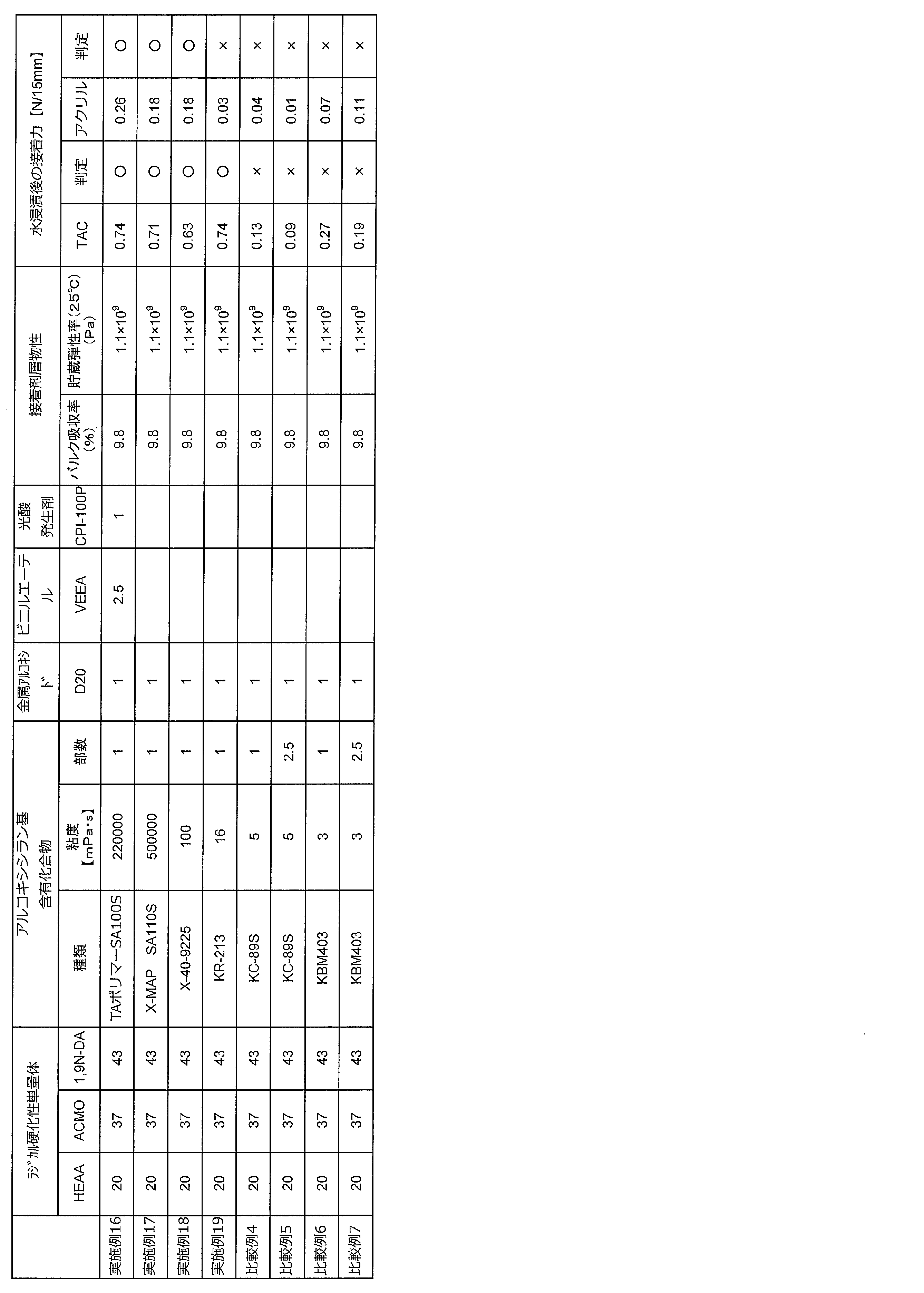
表4中、アルコキシシラン基含有化合物は、
TAポリマーSA100S:主鎖(メタ)アクリル系ポリマータイプ、カネカ社製
X-MAP SA110S:主鎖(メタ)アクリル系ポリマータイプ、カネカ社製
X-40-9225:オリゴマー型アルコキシシラン基含有化合物、信越シリコーン社製、
KR-213:オリゴマー型アルコキシシラン基含有化合物、信越シリコーン社製、
KC-89S:低分子量アルコキシシラン基含有化合物、信越シリコーン社製、
KBM403:低分子量アルコキシシラン基含有化合物、信越シリコーン社製、
を示す。
TAポリマーSA100S:主鎖(メタ)アクリル系ポリマータイプ、カネカ社製
X-MAP SA110S:主鎖(メタ)アクリル系ポリマータイプ、カネカ社製
X-40-9225:オリゴマー型アルコキシシラン基含有化合物、信越シリコーン社製、
KR-213:オリゴマー型アルコキシシラン基含有化合物、信越シリコーン社製、
KC-89S:低分子量アルコキシシラン基含有化合物、信越シリコーン社製、
KBM403:低分子量アルコキシシラン基含有化合物、信越シリコーン社製、
を示す。
Claims (26)
- 偏光子の少なくとも一方の面に、接着剤層を介して透明保護フィルムが積層された偏光フィルムであって、
前記接着剤層は、活性エネルギー線硬化型接着剤組成物に活性エネルギー線を照射して得られた硬化物層により形成されたものであり、
前記活性エネルギー線硬化型接着剤組成物は、オクタノール/水分配係数を表すlogPowが-1~1であるA成分と、logPowが2~7であるB成分とを含有し、
前記接着剤層は、前記偏光子側での前記A成分の濃度が高いことを特徴とする偏光フィルム。 - 前記活性エネルギー線硬化型接着剤組成物が、前記A成分として(メタ)アクリルアミド誘導体を含有する請求項1に記載の偏光フィルム。
- 前記活性エネルギー線硬化型接着剤組成物が、前記B成分として多官能(メタ)アクリレートを含有する請求項1または2に記載の偏光フィルム。
- 前記活性エネルギー線硬化型接着剤組成物が、(メタ)アクリルモノマーを重合してなるアクリル系オリゴマーを含有する請求項1~3のいずれかに記載の偏光フィルム。
- 前記活性エネルギー線硬化型接着剤組成物が、ヒドロキシル基含有光重合開始剤を含有する請求項1~4のいずれかに記載の偏光フィルム。
- 前記活性エネルギー線硬化型接着剤組成物が、金属アルコキシドおよび金属キレートからなる群より選択される少なくとも1種の有機金属化合物を含有する請求項1~5のいずれかに記載の偏光フィルム。
- 前記活性エネルギー線硬化型接着剤組成物が含有する前記有機金属化合物の金属がチタンである請求項6に記載の偏光フィルム。
- 前記活性エネルギー線硬化型接着剤組成物が、前記有機金属化合物として前記金属アルコキシドを含有し、前記金属アルコキシドが有する有機基の炭素数が6以上である請求項6または7に記載の偏光フィルム。
- 前記活性エネルギー線硬化型接着剤組成物が、前記有機金属化合物として前記金属キレートを含有し、前記金属キレートが有する有機基の炭素数が4以上である請求項6または7に記載の偏光フィルム。
- 粘度が15mPa・s以上であるアルコキシシラン基含有化合物を含有する請求項1~9のいずれかに記載の偏光フィルム。
- 前記アルコキシシラン基含有化合物の主鎖が、アクリル系ポリマー構造である請求項10に記載の偏光フィルム。
- 前記活性エネルギー線硬化型接着剤組成物を硬化させて得られる接着剤層の、25℃における貯蔵弾性率が1.0×10⁷Pa以上である請求項1~11のいずれかに記載の偏光フィルム。
- 請求項1~12のいずれかに記載の偏光フィルムの製造方法であって、
前記偏光子および前記透明保護フィルムの少なくとも一方の面に、前記活性エネルギー線硬化型接着剤組成物を塗工する塗工工程と、
前記偏光子および前記透明保護フィルムを貼り合わせる貼合工程と、
前記偏光子面側または前記透明保護フィルム面側から活性エネルギー線を照射して、前記活性エネルギー線硬化型接着剤組成物を硬化させることにより得られた前記接着剤層を介して、前記偏光子および前記透明保護フィルムを接着させる接着工程とを含み、
前記塗工工程後、前記接着工程までの間、前記活性エネルギー線硬化型接着剤組成物の温度を15~40℃に調整することを特徴とする偏光フィルムの製造方法。 - 偏光子の少なくとも一方の面に、接着剤層を介して透明保護フィルムが積層された偏光フィルムの製造方法であって、
前記接着剤層は、活性エネルギー線硬化型接着剤組成物に活性エネルギー線を照射して得られた硬化物層により形成されたものであり、
前記偏光子の貼合面に、オクタノール/水分配係数を表すlogPowが-1~1であるA成分を含有する第1活性エネルギー線硬化型接着剤組成物を塗工する第1塗工工程と、
前記透明保護フィルムの貼合面に、logPowが2~7であるB成分を含有する第2活性エネルギー線硬化型接着剤組成物を塗工する第2塗工工程と、
前記偏光子および前記透明保護フィルムを貼り合わせる貼合工程と、
前記偏光子面側または前記透明保護フィルム面側から活性エネルギー線を照射して、前記活性エネルギー線硬化型接着剤組成物を硬化させることにより得られた前記接着剤層を介して、前記偏光子および前記透明保護フィルムを接着させる接着工程とを含み、
前記接着工程後に形成される前記接着剤層が、前記偏光子側での前記A成分の濃度が高いことを特徴とする偏光フィルムの製造方法。 - 前記活性エネルギー線硬化型接着剤組成物が、前記A成分として(メタ)アクリルアミド誘導体を含有する請求項14に記載の偏光フィルムの製造方法。
- 前記活性エネルギー線硬化型接着剤組成物が、前記B成分として多官能(メタ)アクリレートを含有する請求項14または15に記載の偏光フィルムの製造方法。
- 前記活性エネルギー線硬化型接着剤組成物が、(メタ)アクリルモノマーを重合してなるアクリル系オリゴマーを含有する請求項14~16のいずれかに記載の偏光フィルムの製造方法。
- 前記活性エネルギー線硬化型接着剤組成物が、ヒドロキシル基含有光重合開始剤を含有する請求項14~17のいずれかに記載の偏光フィルムの製造方法。
- 前記活性エネルギー線硬化型接着剤組成物が、金属アルコキシドおよび金属キレートからなる群より選択される少なくとも1種の有機金属化合物を含有する請求項14~18のいずれかに記載の偏光フィルムの製造方法。
- 前記第1活性エネルギー線硬化型接着剤組成物が、前記有機金属化合物を含有する請求項19に記載の偏光フィルムの製造方法。
- 前記活性エネルギー線硬化型接着剤組成物が含有する前記有機金属化合物の金属がチタンである請求項19または20に記載の偏光フィルムの製造方法。
- 前記活性エネルギー線硬化型接着剤組成物が、前記有機金属化合物として前記金属アルコキシドを含有し、前記金属アルコキシドが有する有機基の炭素数が6以上である請求項19~21のいずれかに記載の偏光フィルムの製造方法。
- 前記活性エネルギー線硬化型接着剤組成物が、前記有機金属化合物として前記金属キレートを含有し、前記金属キレートが有する有機基の炭素数が4以上である請求項19~22のいずれかに記載の偏光フィルムの製造方法。
- 粘度が15mPa・s以上であるアルコキシシラン基含有化合物を含有する請求項14~23のいずれかに記載の偏光フィルムの製造方法。
- 前記アルコキシシラン基含有化合物の主鎖が、アクリル系ポリマー構造である請求項24に記載の偏光フィルムの製造方法。
- 前記活性エネルギー線硬化型接着剤組成物を硬化させて得られる接着剤層の、25℃における貯蔵弾性率が1.0×10⁷Pa以上である請求項17~21のいずれかに記載の偏光フィルムの製造方法。
Priority Applications (2)
| Application Number | Priority Date | Filing Date | Title |
|---|---|---|---|
| KR1020177000623A KR102434552B1 (ko) | 2014-07-16 | 2015-07-14 | 편광 필름 및 그 제조 방법 |
| CN201580038040.8A CN106662692B (zh) | 2014-07-16 | 2015-07-14 | 偏振膜及其制造方法 |
Applications Claiming Priority (6)
| Application Number | Priority Date | Filing Date | Title |
|---|---|---|---|
| JP2014-146061 | 2014-07-16 | ||
| JP2014146061 | 2014-07-16 | ||
| JP2015062990 | 2015-03-25 | ||
| JP2015-062990 | 2015-03-25 | ||
| JP2015139729A JP6633308B2 (ja) | 2014-07-16 | 2015-07-13 | 偏光フィルムおよびその製造方法 |
| JP2015-139729 | 2015-07-13 |
Publications (1)
| Publication Number | Publication Date |
|---|---|
| WO2016010031A1 true WO2016010031A1 (ja) | 2016-01-21 |
Family
ID=55078521
Family Applications (1)
| Application Number | Title | Priority Date | Filing Date |
|---|---|---|---|
| PCT/JP2015/070141 WO2016010031A1 (ja) | 2014-07-16 | 2015-07-14 | 偏光フィルムおよびその製造方法 |
Country Status (3)
| Country | Link |
|---|---|
| CN (1) | CN111458783B (ja) |
| TW (1) | TWI705893B (ja) |
| WO (1) | WO2016010031A1 (ja) |
Cited By (13)
| Publication number | Priority date | Publication date | Assignee | Title |
|---|---|---|---|---|
| WO2016152564A1 (ja) * | 2015-03-25 | 2016-09-29 | 日東電工株式会社 | 偏光フィルム用硬化型接着剤組成物、偏光フィルムおよびその製造方法、光学フィルムならびに画像表示装置 |
| WO2017010225A1 (ja) * | 2015-07-13 | 2017-01-19 | 日東電工株式会社 | 偏光フィルム用硬化型接着剤組成物、偏光フィルムおよびその製造方法、光学フィルムならびに画像表示装置 |
| JP2017137376A (ja) * | 2016-02-01 | 2017-08-10 | 積水化学工業株式会社 | 高弾性接着剤及びキーシート接合用接着剤 |
| JP2017160313A (ja) * | 2016-03-09 | 2017-09-14 | 日東電工株式会社 | 硬化性樹脂組成物、偏光フィルムおよびその製造方法、光学フィルムならびに画像表示装置 |
| WO2017183333A1 (ja) * | 2016-04-20 | 2017-10-26 | 日東電工株式会社 | 活性エネルギー線硬化型接着剤組成物、積層偏光フィルムおよびその製造方法、積層光学フィルムおよび画像表示装置 |
| WO2017199978A1 (ja) * | 2016-05-17 | 2017-11-23 | 日東電工株式会社 | 偏光フィルムおよびその製造方法、光学フィルム、画像表示装置ならびに易接着処理偏光子 |
| WO2018008443A1 (ja) * | 2016-07-08 | 2018-01-11 | 日東電工株式会社 | 粘着層付き偏光フィルムおよび該粘着層付き偏光フィルムの製造方法 |
| JP2018013769A (ja) * | 2016-07-08 | 2018-01-25 | 日東電工株式会社 | 粘着層付き偏光フィルムおよび該粘着層付き偏光フィルムの製造方法 |
| WO2018161079A1 (en) | 2017-03-03 | 2018-09-07 | Harland Medical Systems, Inc. | Coating composition comprised of a hydrophilic crosslinker, a hydrophobic crosslinker and optionally a hydrogel and methods of making and using the same |
| KR20190040190A (ko) * | 2016-08-17 | 2019-04-17 | 닛폰고세이가가쿠고교 가부시키가이샤 | 아크릴계 점착제 조성물, 및 이를 사용하여 이루어진 점착제, 편광판용 점착제, 및 화상 표시장치 |
| CN109690368A (zh) * | 2016-11-04 | 2019-04-26 | 日本合成化学工业株式会社 | 偏光板用粘合剂组合物、偏光板用粘合剂、以及带粘合剂层的偏光板 |
| WO2019163743A1 (ja) * | 2018-02-26 | 2019-08-29 | 日東電工株式会社 | 活性エネルギー線硬化型接着剤組成物、偏光フィルムおよびその製造方法、光学フィルム、ならびに画像表示装置 |
| WO2022113842A1 (ja) * | 2020-11-30 | 2022-06-02 | 日東電工株式会社 | 偏光板およびそれを用いた画像表示装置 |
Families Citing this family (3)
| Publication number | Priority date | Publication date | Assignee | Title |
|---|---|---|---|---|
| JP6868343B2 (ja) * | 2016-04-20 | 2021-05-12 | 日東電工株式会社 | 偏光フィルムおよびその製造方法、光学フィルムおよび画像表示装置 |
| JP7213037B2 (ja) * | 2018-08-23 | 2023-01-26 | 日東電工株式会社 | 偏光子、偏光フィルム、光学フィルム、ならびに画像表示装置 |
| JP6535799B1 (ja) * | 2018-08-27 | 2019-06-26 | 日東電工株式会社 | 延伸樹脂膜の製造方法、偏光子の製造方法、および延伸樹脂膜の製造装置 |
Citations (8)
| Publication number | Priority date | Publication date | Assignee | Title |
|---|---|---|---|---|
| JPH09318814A (ja) * | 1996-05-29 | 1997-12-12 | Nitto Denko Corp | 偏光板用接着剤および偏光板 |
| JP2009292917A (ja) * | 2008-06-04 | 2009-12-17 | Seiko Epson Corp | 接合方法および接合体 |
| JP2013112715A (ja) * | 2011-11-28 | 2013-06-10 | Toagosei Co Ltd | 活性エネルギー線硬化型接着剤組成物 |
| JP2013112693A (ja) * | 2011-11-25 | 2013-06-10 | Toagosei Co Ltd | 硬化型接着剤組成物 |
| JP2013178466A (ja) * | 2012-02-06 | 2013-09-09 | Kohjin Holdings Co Ltd | 偏光板用活性エネルギー線硬化性接着剤 |
| JP2013216765A (ja) * | 2012-04-06 | 2013-10-24 | Cheil Industries Inc | 偏光板用接着剤組成物およびこれを用いた偏光板 |
| WO2015030203A1 (ja) * | 2013-08-30 | 2015-03-05 | 日東電工株式会社 | 偏光フィルム用硬化型接着剤、偏光フィルム、光学フィルムおよび画像表示装置 |
| JP5703476B1 (ja) * | 2013-07-04 | 2015-04-22 | 東洋インキScホールディングス株式会社 | 活性エネルギー線重合性接着剤、及び積層体 |
Family Cites Families (25)
| Publication number | Priority date | Publication date | Assignee | Title |
|---|---|---|---|---|
| DE19500241A1 (de) * | 1995-01-05 | 1996-07-11 | Thera Ges Fuer Patente | Radikalisch polymerisierbare Zubereitungen und ihre Verwendung |
| JP3373492B2 (ja) * | 2000-11-07 | 2003-02-04 | 日東電工株式会社 | 偏光板 |
| JP4832748B2 (ja) * | 2004-02-26 | 2011-12-07 | 日東電工株式会社 | 帯電防止性粘着型光学フィルム、その製造方法および画像表示装置 |
| CN100470271C (zh) * | 2004-02-26 | 2009-03-18 | 富士胶片株式会社 | 光学薄膜、光学补偿薄片、偏振片和液晶显示装置 |
| JP4039682B2 (ja) * | 2006-06-09 | 2008-01-30 | 日東電工株式会社 | 偏光板用接着剤、偏光板、その製造方法、光学フィルムおよび画像表示装置 |
| JP2008209895A (ja) * | 2007-01-31 | 2008-09-11 | Nitto Denko Corp | 連結組み合わせ型光学フィルム、液晶パネル、画像表示装置および液晶表示装置 |
| JP4744496B2 (ja) * | 2007-04-16 | 2011-08-10 | 日東電工株式会社 | 偏光板、光学フィルムおよび画像表示装置 |
| JP4991421B2 (ja) * | 2007-07-13 | 2012-08-01 | リンテック株式会社 | 粘着剤、粘着シート及び粘着剤付き光学フィルム |
| JP5340649B2 (ja) * | 2007-10-22 | 2013-11-13 | 日東電工株式会社 | 光学フィルム用粘着剤組成物、光学フィルム用粘着剤層、その製造方法、粘着型光学フィルムおよび画像表示装置 |
| JP5637615B2 (ja) * | 2008-01-17 | 2014-12-10 | 日東電工株式会社 | 偏光板、その製造方法、光学フィルムおよび画像表示装置 |
| JP5331537B2 (ja) * | 2008-03-28 | 2013-10-30 | 富士フイルム株式会社 | 透明支持体、光学フィルム、偏光板、および画像表示装置 |
| JP4762320B2 (ja) * | 2009-02-20 | 2011-08-31 | 住友化学株式会社 | 液晶表示装置 |
| JP5296575B2 (ja) * | 2009-03-06 | 2013-09-25 | 住友化学株式会社 | 光硬化性接着剤組成物、偏光板とその製造法、光学部材及び液晶表示装置 |
| JP4428470B1 (ja) * | 2009-06-08 | 2010-03-10 | 東洋インキ製造株式会社 | 偏光板及び偏光板形成用接着剤組成物 |
| JP5518436B2 (ja) * | 2009-11-09 | 2014-06-11 | 日東電工株式会社 | 光学用粘着シート |
| JP2011236298A (ja) * | 2010-05-07 | 2011-11-24 | Bridgestone Corp | 接着性組成物、フレキシブル情報表示パネル及びフレキシブル情報表示パネルの製造方法 |
| JP5562173B2 (ja) * | 2010-08-19 | 2014-07-30 | リンテック株式会社 | 粘着性組成物、粘着剤および粘着シート |
| KR101072371B1 (ko) * | 2010-09-20 | 2011-10-11 | 주식회사 엘지화학 | 편광판용 접착제 및 이를 포함하는 편광판 |
| JP5968587B2 (ja) * | 2010-10-21 | 2016-08-10 | 日東電工株式会社 | 光学用粘着シート、光学フィルムおよび表示装置 |
| JP5712892B2 (ja) * | 2010-11-29 | 2015-05-07 | 住友化学株式会社 | 偏光板の製造方法 |
| JP2012179878A (ja) * | 2011-03-03 | 2012-09-20 | Sony Corp | 光学積層体およびその製造方法、ならびに表示装置 |
| CN102135638A (zh) * | 2011-03-07 | 2011-07-27 | 深圳市盛波光电科技有限公司 | 一种软胶型3d立体眼镜用偏光片 |
| JP5774349B2 (ja) * | 2011-04-01 | 2015-09-09 | 住友化学株式会社 | 偏光板の製造方法 |
| JP5790133B2 (ja) * | 2011-05-09 | 2015-10-07 | 住友化学株式会社 | 活性エネルギー線硬化型接着剤を用いる偏光板の製造方法 |
| KR20130015935A (ko) * | 2011-08-05 | 2013-02-14 | 동우 화인켐 주식회사 | 방현성 반사방지 코팅 조성물, 이를 이용한 방현성 반사방지 필름, 편광판 및 표시장치 |
-
2015
- 2015-07-14 CN CN202010382163.6A patent/CN111458783B/zh active Active
- 2015-07-14 WO PCT/JP2015/070141 patent/WO2016010031A1/ja active Application Filing
- 2015-07-15 TW TW104122904A patent/TWI705893B/zh active
Patent Citations (8)
| Publication number | Priority date | Publication date | Assignee | Title |
|---|---|---|---|---|
| JPH09318814A (ja) * | 1996-05-29 | 1997-12-12 | Nitto Denko Corp | 偏光板用接着剤および偏光板 |
| JP2009292917A (ja) * | 2008-06-04 | 2009-12-17 | Seiko Epson Corp | 接合方法および接合体 |
| JP2013112693A (ja) * | 2011-11-25 | 2013-06-10 | Toagosei Co Ltd | 硬化型接着剤組成物 |
| JP2013112715A (ja) * | 2011-11-28 | 2013-06-10 | Toagosei Co Ltd | 活性エネルギー線硬化型接着剤組成物 |
| JP2013178466A (ja) * | 2012-02-06 | 2013-09-09 | Kohjin Holdings Co Ltd | 偏光板用活性エネルギー線硬化性接着剤 |
| JP2013216765A (ja) * | 2012-04-06 | 2013-10-24 | Cheil Industries Inc | 偏光板用接着剤組成物およびこれを用いた偏光板 |
| JP5703476B1 (ja) * | 2013-07-04 | 2015-04-22 | 東洋インキScホールディングス株式会社 | 活性エネルギー線重合性接着剤、及び積層体 |
| WO2015030203A1 (ja) * | 2013-08-30 | 2015-03-05 | 日東電工株式会社 | 偏光フィルム用硬化型接着剤、偏光フィルム、光学フィルムおよび画像表示装置 |
Cited By (30)
| Publication number | Priority date | Publication date | Assignee | Title |
|---|---|---|---|---|
| WO2016152564A1 (ja) * | 2015-03-25 | 2016-09-29 | 日東電工株式会社 | 偏光フィルム用硬化型接着剤組成物、偏光フィルムおよびその製造方法、光学フィルムならびに画像表示装置 |
| WO2017010225A1 (ja) * | 2015-07-13 | 2017-01-19 | 日東電工株式会社 | 偏光フィルム用硬化型接着剤組成物、偏光フィルムおよびその製造方法、光学フィルムならびに画像表示装置 |
| JP2017021239A (ja) * | 2015-07-13 | 2017-01-26 | 日東電工株式会社 | 偏光フィルム用硬化型接着剤組成物、偏光フィルムおよびその製造方法、光学フィルムならびに画像表示装置 |
| JP2017137376A (ja) * | 2016-02-01 | 2017-08-10 | 積水化学工業株式会社 | 高弾性接着剤及びキーシート接合用接着剤 |
| CN108603035A (zh) * | 2016-03-09 | 2018-09-28 | 日东电工株式会社 | 固化性树脂组合物、偏振膜及其制造方法、光学膜以及图像显示装置 |
| JP2017160313A (ja) * | 2016-03-09 | 2017-09-14 | 日東電工株式会社 | 硬化性樹脂組成物、偏光フィルムおよびその製造方法、光学フィルムならびに画像表示装置 |
| US10899946B2 (en) | 2016-03-09 | 2021-01-26 | Nitto Denko Corporation | Curable resin composition, polarizing film and production process therefor, optical film, and image display device |
| WO2017183333A1 (ja) * | 2016-04-20 | 2017-10-26 | 日東電工株式会社 | 活性エネルギー線硬化型接着剤組成物、積層偏光フィルムおよびその製造方法、積層光学フィルムおよび画像表示装置 |
| JP2017193634A (ja) * | 2016-04-20 | 2017-10-26 | 日東電工株式会社 | 活性エネルギー線硬化型接着剤組成物、積層偏光フィルムおよびその製造方法、積層光学フィルムおよび画像表示装置 |
| WO2017199978A1 (ja) * | 2016-05-17 | 2017-11-23 | 日東電工株式会社 | 偏光フィルムおよびその製造方法、光学フィルム、画像表示装置ならびに易接着処理偏光子 |
| JP2022062073A (ja) * | 2016-05-17 | 2022-04-19 | 日東電工株式会社 | 偏光フィルムおよびその製造方法、光学フィルム、画像表示装置ならびに易接着処理偏光子 |
| JP7278075B2 (ja) | 2016-05-17 | 2023-05-19 | 日東電工株式会社 | 偏光フィルムおよびその製造方法、光学フィルム、画像表示装置ならびに易接着処理偏光子 |
| CN109073812A (zh) * | 2016-05-17 | 2018-12-21 | 日东电工株式会社 | 偏振膜及其制造方法、光学膜、图像显示装置以及易粘接处理起偏镜 |
| TWI777952B (zh) * | 2016-05-17 | 2022-09-21 | 日商日東電工股份有限公司 | 偏光薄膜及其製造方法、光學薄膜、影像顯示裝置以及易接著處理偏光件 |
| US11061175B2 (en) | 2016-05-17 | 2021-07-13 | Nitto Denko Corporation | Polarizing film, method for producing same, optical film, image display device, and adhesion improvement-treated polarizer |
| JPWO2017199978A1 (ja) * | 2016-05-17 | 2019-03-14 | 日東電工株式会社 | 偏光フィルムおよびその製造方法、光学フィルム、画像表示装置ならびに易接着処理偏光子 |
| JP2018013769A (ja) * | 2016-07-08 | 2018-01-25 | 日東電工株式会社 | 粘着層付き偏光フィルムおよび該粘着層付き偏光フィルムの製造方法 |
| CN109313304A (zh) * | 2016-07-08 | 2019-02-05 | 日东电工株式会社 | 带粘合层的偏振膜及该带粘合层的偏振膜的制造方法 |
| WO2018008443A1 (ja) * | 2016-07-08 | 2018-01-11 | 日東電工株式会社 | 粘着層付き偏光フィルムおよび該粘着層付き偏光フィルムの製造方法 |
| KR102261968B1 (ko) * | 2016-07-08 | 2021-06-07 | 닛토덴코 가부시키가이샤 | 점착층 부착 편광 필름 및 그 점착층 부착 편광 필름의 제조 방법 |
| KR20190025842A (ko) * | 2016-07-08 | 2019-03-12 | 닛토덴코 가부시키가이샤 | 점착층 부착 편광 필름 및 그 점착층 부착 편광 필름의 제조 방법 |
| KR102358555B1 (ko) | 2016-08-17 | 2022-02-04 | 미쯔비시 케미컬 주식회사 | 아크릴계 점착제 조성물, 및 이를 사용하여 이루어진 점착제, 편광판용 점착제, 및 화상 표시장치 |
| KR20190040190A (ko) * | 2016-08-17 | 2019-04-17 | 닛폰고세이가가쿠고교 가부시키가이샤 | 아크릴계 점착제 조성물, 및 이를 사용하여 이루어진 점착제, 편광판용 점착제, 및 화상 표시장치 |
| CN109690368A (zh) * | 2016-11-04 | 2019-04-26 | 日本合成化学工业株式会社 | 偏光板用粘合剂组合物、偏光板用粘合剂、以及带粘合剂层的偏光板 |
| WO2018161079A1 (en) | 2017-03-03 | 2018-09-07 | Harland Medical Systems, Inc. | Coating composition comprised of a hydrophilic crosslinker, a hydrophobic crosslinker and optionally a hydrogel and methods of making and using the same |
| EP3589704A4 (en) * | 2017-03-03 | 2020-12-16 | Harland Medical Systems, Inc. | COATING COMPOSITION WITH A HYDROPHILIC CROSSLINKER, A HYDROPHOBIC CROSSLINKER AND, IF APPLICABLE, A HYDROGEL AND A METHOD FOR MANUFACTURING AND USING THEREOF |
| JP7137900B2 (ja) | 2018-02-26 | 2022-09-15 | 日東電工株式会社 | 活性エネルギー線硬化型接着剤組成物、偏光フィルムおよびその製造方法、光学フィルム、ならびに画像表示装置 |
| JP2019147865A (ja) * | 2018-02-26 | 2019-09-05 | 日東電工株式会社 | 活性エネルギー線硬化型接着剤組成物、偏光フィルムおよびその製造方法、光学フィルム、ならびに画像表示装置 |
| WO2019163743A1 (ja) * | 2018-02-26 | 2019-08-29 | 日東電工株式会社 | 活性エネルギー線硬化型接着剤組成物、偏光フィルムおよびその製造方法、光学フィルム、ならびに画像表示装置 |
| WO2022113842A1 (ja) * | 2020-11-30 | 2022-06-02 | 日東電工株式会社 | 偏光板およびそれを用いた画像表示装置 |
Also Published As
| Publication number | Publication date |
|---|---|
| TWI705893B (zh) | 2020-10-01 |
| TW201609389A (zh) | 2016-03-16 |
| CN111458783A (zh) | 2020-07-28 |
| CN111458783B (zh) | 2022-02-11 |
Similar Documents
| Publication | Publication Date | Title |
|---|---|---|
| JP6936355B2 (ja) | 偏光フィルムおよびその製造方法、光学フィルムならびに画像表示装置 | |
| WO2016010031A1 (ja) | 偏光フィルムおよびその製造方法 | |
| JP7019659B2 (ja) | 偏光フィルムおよびその製造方法 | |
| JP7278075B2 (ja) | 偏光フィルムおよびその製造方法、光学フィルム、画像表示装置ならびに易接着処理偏光子 | |
| JP6868345B2 (ja) | 硬化性樹脂組成物、偏光フィルムおよびその製造方法、光学フィルムならびに画像表示装置 | |
| JP6376872B2 (ja) | 積層光学フィルムの製造方法 | |
| JP6560999B2 (ja) | 硬化性樹脂組成物、偏光フィルムおよびその製造方法、光学フィルムならびに画像表示装置 | |
| WO2016143435A1 (ja) | 架橋剤および硬化性樹脂組成物、偏光フィルムおよびその製造方法、光学フィルムならびに画像表示装置 | |
| WO2016143885A1 (ja) | 偏光フィルムおよびその製造方法、光学フィルムならびに画像表示装置 | |
| WO2017135121A1 (ja) | 硬化性樹脂組成物 | |
| KR102261968B1 (ko) | 점착층 부착 편광 필름 및 그 점착층 부착 편광 필름의 제조 방법 | |
| JP6786328B2 (ja) | 偏光フィルム用硬化型接着剤組成物およびその製造方法、偏光フィルムおよびその製造方法、光学フィルムならびに画像表示装置 | |
| WO2017010225A1 (ja) | 偏光フィルム用硬化型接着剤組成物、偏光フィルムおよびその製造方法、光学フィルムならびに画像表示装置 | |
| WO2017010224A1 (ja) | 偏光フィルム用硬化型接着剤組成物、偏光フィルムおよびその製造方法、光学フィルムならびに画像表示装置 | |
| WO2017057615A1 (ja) | 偏光フィルム用硬化型接着剤組成物およびその製造方法、偏光フィルムおよびその製造方法、光学フィルムならびに画像表示装置 | |
| JP6712846B2 (ja) | 偏光フィルム用硬化型接着剤組成物、偏光フィルムおよびその製造方法、光学フィルムならびに画像表示装置 | |
| WO2018008443A1 (ja) | 粘着層付き偏光フィルムおよび該粘着層付き偏光フィルムの製造方法 | |
| WO2016152564A1 (ja) | 偏光フィルム用硬化型接着剤組成物、偏光フィルムおよびその製造方法、光学フィルムならびに画像表示装置 | |
| JP6841629B2 (ja) | 有機金属化合物含有組成物 | |
| JP2018165840A (ja) | 積層光学フィルムの製造方法 |
Legal Events
| Date | Code | Title | Description |
|---|---|---|---|
| 121 | Ep: the epo has been informed by wipo that ep was designated in this application |
Ref document number: 15821346 Country of ref document: EP Kind code of ref document: A1 |
|
| ENP | Entry into the national phase |
Ref document number: 20177000623 Country of ref document: KR Kind code of ref document: A |
|
| NENP | Non-entry into the national phase |
Ref country code: DE |
|
| 122 | Ep: pct application non-entry in european phase |
Ref document number: 15821346 Country of ref document: EP Kind code of ref document: A1 |