WO2016006564A1 - ゼオライト膜、その製造方法およびこれを用いた分離方法 - Google Patents
ゼオライト膜、その製造方法およびこれを用いた分離方法 Download PDFInfo
- Publication number
- WO2016006564A1 WO2016006564A1 PCT/JP2015/069394 JP2015069394W WO2016006564A1 WO 2016006564 A1 WO2016006564 A1 WO 2016006564A1 JP 2015069394 W JP2015069394 W JP 2015069394W WO 2016006564 A1 WO2016006564 A1 WO 2016006564A1
- Authority
- WO
- WIPO (PCT)
- Prior art keywords
- separation
- zeolite
- zeolite membrane
- membrane
- cha
- Prior art date
- Legal status (The legal status is an assumption and is not a legal conclusion. Google has not performed a legal analysis and makes no representation as to the accuracy of the status listed.)
- Ceased
Links
Images


Classifications
-
- B—PERFORMING OPERATIONS; TRANSPORTING
- B01—PHYSICAL OR CHEMICAL PROCESSES OR APPARATUS IN GENERAL
- B01D—SEPARATION
- B01D71/00—Semi-permeable membranes for separation processes or apparatus characterised by the material; Manufacturing processes specially adapted therefor
- B01D71/02—Inorganic material
- B01D71/028—Molecular sieves
- B01D71/0281—Zeolites
-
- B—PERFORMING OPERATIONS; TRANSPORTING
- B01—PHYSICAL OR CHEMICAL PROCESSES OR APPARATUS IN GENERAL
- B01D—SEPARATION
- B01D53/00—Separation of gases or vapours; Recovering vapours of volatile solvents from gases; Chemical or biological purification of waste gases, e.g. engine exhaust gases, smoke, fumes, flue gases, aerosols
- B01D53/22—Separation of gases or vapours; Recovering vapours of volatile solvents from gases; Chemical or biological purification of waste gases, e.g. engine exhaust gases, smoke, fumes, flue gases, aerosols by diffusion
-
- B—PERFORMING OPERATIONS; TRANSPORTING
- B01—PHYSICAL OR CHEMICAL PROCESSES OR APPARATUS IN GENERAL
- B01D—SEPARATION
- B01D53/00—Separation of gases or vapours; Recovering vapours of volatile solvents from gases; Chemical or biological purification of waste gases, e.g. engine exhaust gases, smoke, fumes, flue gases, aerosols
- B01D53/22—Separation of gases or vapours; Recovering vapours of volatile solvents from gases; Chemical or biological purification of waste gases, e.g. engine exhaust gases, smoke, fumes, flue gases, aerosols by diffusion
- B01D53/228—Separation of gases or vapours; Recovering vapours of volatile solvents from gases; Chemical or biological purification of waste gases, e.g. engine exhaust gases, smoke, fumes, flue gases, aerosols by diffusion characterised by specific membranes
-
- B—PERFORMING OPERATIONS; TRANSPORTING
- B01—PHYSICAL OR CHEMICAL PROCESSES OR APPARATUS IN GENERAL
- B01D—SEPARATION
- B01D67/00—Processes specially adapted for manufacturing semi-permeable membranes for separation processes or apparatus
- B01D67/0039—Inorganic membrane manufacture
- B01D67/0051—Inorganic membrane manufacture by controlled crystallisation, e,.g. hydrothermal growth
-
- B—PERFORMING OPERATIONS; TRANSPORTING
- B01—PHYSICAL OR CHEMICAL PROCESSES OR APPARATUS IN GENERAL
- B01D—SEPARATION
- B01D69/00—Semi-permeable membranes for separation processes or apparatus characterised by their form, structure or properties; Manufacturing processes specially adapted therefor
- B01D69/10—Supported membranes; Membrane supports
- B01D69/108—Inorganic support material
-
- B—PERFORMING OPERATIONS; TRANSPORTING
- B01—PHYSICAL OR CHEMICAL PROCESSES OR APPARATUS IN GENERAL
- B01D—SEPARATION
- B01D69/00—Semi-permeable membranes for separation processes or apparatus characterised by their form, structure or properties; Manufacturing processes specially adapted therefor
- B01D69/12—Composite membranes; Ultra-thin membranes
-
- B—PERFORMING OPERATIONS; TRANSPORTING
- B01—PHYSICAL OR CHEMICAL PROCESSES OR APPARATUS IN GENERAL
- B01J—CHEMICAL OR PHYSICAL PROCESSES, e.g. CATALYSIS OR COLLOID CHEMISTRY; THEIR RELEVANT APPARATUS
- B01J20/00—Solid sorbent compositions or filter aid compositions; Sorbents for chromatography; Processes for preparing, regenerating or reactivating thereof
- B01J20/02—Solid sorbent compositions or filter aid compositions; Sorbents for chromatography; Processes for preparing, regenerating or reactivating thereof comprising inorganic material
- B01J20/10—Solid sorbent compositions or filter aid compositions; Sorbents for chromatography; Processes for preparing, regenerating or reactivating thereof comprising inorganic material comprising silica or silicate
- B01J20/16—Alumino-silicates
- B01J20/18—Synthetic zeolitic molecular sieves
-
- B—PERFORMING OPERATIONS; TRANSPORTING
- B01—PHYSICAL OR CHEMICAL PROCESSES OR APPARATUS IN GENERAL
- B01J—CHEMICAL OR PHYSICAL PROCESSES, e.g. CATALYSIS OR COLLOID CHEMISTRY; THEIR RELEVANT APPARATUS
- B01J20/00—Solid sorbent compositions or filter aid compositions; Sorbents for chromatography; Processes for preparing, regenerating or reactivating thereof
- B01J20/30—Processes for preparing, regenerating, or reactivating
- B01J20/32—Impregnating or coating ; Solid sorbent compositions obtained from processes involving impregnating or coating
- B01J20/3231—Impregnating or coating ; Solid sorbent compositions obtained from processes involving impregnating or coating characterised by the coating or impregnating layer
- B01J20/3234—Inorganic material layers
- B01J20/3238—Inorganic material layers containing any type of zeolite
-
- C—CHEMISTRY; METALLURGY
- C01—INORGANIC CHEMISTRY
- C01B—NON-METALLIC ELEMENTS; COMPOUNDS THEREOF; METALLOIDS OR COMPOUNDS THEREOF NOT COVERED BY SUBCLASS C01C
- C01B39/00—Compounds having molecular sieve and base-exchange properties, e.g. crystalline zeolites; Their preparation; After-treatment, e.g. ion-exchange or dealumination
- C01B39/02—Crystalline aluminosilicate zeolites; Isomorphous compounds thereof; Direct preparation thereof; Preparation thereof starting from a reaction mixture containing a crystalline zeolite of another type, or from preformed reactants; After-treatment thereof
- C01B39/026—After-treatment
-
- C—CHEMISTRY; METALLURGY
- C01—INORGANIC CHEMISTRY
- C01B—NON-METALLIC ELEMENTS; COMPOUNDS THEREOF; METALLOIDS OR COMPOUNDS THEREOF NOT COVERED BY SUBCLASS C01C
- C01B39/00—Compounds having molecular sieve and base-exchange properties, e.g. crystalline zeolites; Their preparation; After-treatment, e.g. ion-exchange or dealumination
- C01B39/02—Crystalline aluminosilicate zeolites; Isomorphous compounds thereof; Direct preparation thereof; Preparation thereof starting from a reaction mixture containing a crystalline zeolite of another type, or from preformed reactants; After-treatment thereof
- C01B39/46—Other types characterised by their X-ray diffraction pattern and their defined composition
- C01B39/48—Other types characterised by their X-ray diffraction pattern and their defined composition using at least one organic template directing agent
-
- B—PERFORMING OPERATIONS; TRANSPORTING
- B01—PHYSICAL OR CHEMICAL PROCESSES OR APPARATUS IN GENERAL
- B01D—SEPARATION
- B01D2256/00—Main component in the product gas stream after treatment
- B01D2256/24—Hydrocarbons
-
- B—PERFORMING OPERATIONS; TRANSPORTING
- B01—PHYSICAL OR CHEMICAL PROCESSES OR APPARATUS IN GENERAL
- B01D—SEPARATION
- B01D2256/00—Main component in the product gas stream after treatment
- B01D2256/24—Hydrocarbons
- B01D2256/245—Methane
-
- B—PERFORMING OPERATIONS; TRANSPORTING
- B01—PHYSICAL OR CHEMICAL PROCESSES OR APPARATUS IN GENERAL
- B01D—SEPARATION
- B01D2257/00—Components to be removed
- B01D2257/50—Carbon oxides
- B01D2257/504—Carbon dioxide
-
- B—PERFORMING OPERATIONS; TRANSPORTING
- B01—PHYSICAL OR CHEMICAL PROCESSES OR APPARATUS IN GENERAL
- B01D—SEPARATION
- B01D2257/00—Components to be removed
- B01D2257/80—Water
-
- B—PERFORMING OPERATIONS; TRANSPORTING
- B01—PHYSICAL OR CHEMICAL PROCESSES OR APPARATUS IN GENERAL
- B01D—SEPARATION
- B01D2323/00—Details relating to membrane preparation
- B01D2323/12—Specific ratios of components used
-
- B—PERFORMING OPERATIONS; TRANSPORTING
- B01—PHYSICAL OR CHEMICAL PROCESSES OR APPARATUS IN GENERAL
- B01D—SEPARATION
- B01D2323/00—Details relating to membrane preparation
- B01D2323/24—Use of template or surface directing agents [SDA]
-
- C—CHEMISTRY; METALLURGY
- C01—INORGANIC CHEMISTRY
- C01P—INDEXING SCHEME RELATING TO STRUCTURAL AND PHYSICAL ASPECTS OF SOLID INORGANIC COMPOUNDS
- C01P2004/00—Particle morphology
- C01P2004/60—Particles characterised by their size
- C01P2004/62—Submicrometer sized, i.e. from 0.1-1 micrometer
-
- C—CHEMISTRY; METALLURGY
- C01—INORGANIC CHEMISTRY
- C01P—INDEXING SCHEME RELATING TO STRUCTURAL AND PHYSICAL ASPECTS OF SOLID INORGANIC COMPOUNDS
- C01P2004/00—Particle morphology
- C01P2004/60—Particles characterised by their size
- C01P2004/64—Nanometer sized, i.e. from 1-100 nanometer
-
- Y—GENERAL TAGGING OF NEW TECHNOLOGICAL DEVELOPMENTS; GENERAL TAGGING OF CROSS-SECTIONAL TECHNOLOGIES SPANNING OVER SEVERAL SECTIONS OF THE IPC; TECHNICAL SUBJECTS COVERED BY FORMER USPC CROSS-REFERENCE ART COLLECTIONS [XRACs] AND DIGESTS
- Y02—TECHNOLOGIES OR APPLICATIONS FOR MITIGATION OR ADAPTATION AGAINST CLIMATE CHANGE
- Y02C—CAPTURE, STORAGE, SEQUESTRATION OR DISPOSAL OF GREENHOUSE GASES [GHG]
- Y02C20/00—Capture or disposal of greenhouse gases
- Y02C20/40—Capture or disposal of greenhouse gases of CO2
-
- Y—GENERAL TAGGING OF NEW TECHNOLOGICAL DEVELOPMENTS; GENERAL TAGGING OF CROSS-SECTIONAL TECHNOLOGIES SPANNING OVER SEVERAL SECTIONS OF THE IPC; TECHNICAL SUBJECTS COVERED BY FORMER USPC CROSS-REFERENCE ART COLLECTIONS [XRACs] AND DIGESTS
- Y02—TECHNOLOGIES OR APPLICATIONS FOR MITIGATION OR ADAPTATION AGAINST CLIMATE CHANGE
- Y02P—CLIMATE CHANGE MITIGATION TECHNOLOGIES IN THE PRODUCTION OR PROCESSING OF GOODS
- Y02P20/00—Technologies relating to chemical industry
- Y02P20/151—Reduction of greenhouse gas [GHG] emissions, e.g. CO2
Definitions
- the present invention relates to a zeolite membrane, a production method thereof, and a separation method using the same.
- the zeolite membrane according to the present invention can separate and recover the target compound with high separation performance and throughput, and can be suitably used especially for dehydration from water-containing organic acids and other organic compounds.
- Zeolites have regularly arranged micropores and are generally used in various fields because they have many heat-resistant and chemically stable materials.
- Zeolite is an aluminosilicate in which a part of Si is substituted with Al, and has pores of molecular order (about 0.3 to 1 nm) from an oxygen 8-membered ring to a 14-membered ring, and has a stereoselective adsorption action.
- it is widely used in the fields of liquid separation, vapor separation, gas separation, membrane reactor, solid acid catalyst, separation adsorbent, ion exchange agent and the like.
- a hydrothermal synthesis method that is, a large amount of water and an organic template such as an aluminum source, a silica source, an alkali metal, and amines are formulated so as to have a desired product zeolite composition
- the preparation is sealed in a pressure vessel such as an autoclave, and heated in the presence of a porous support to synthesize a zeolite membrane on the support.
- the support is composed of alumina, mullite, porous metal, Vycor glass, or the like, and in some cases, seed crystals are attached thereto.
- Patent Document 1 has a CHA-type crystal structure by hydrothermal synthesis using an Si element source, an Al element source, an alkali source containing potassium, and an aqueous reaction mixture containing a 1-adamantanamine derivative as an organic template.
- a method for forming a zeolite membrane on a porous support is described.
- zeolite membrane having the CHA-type crystal structure obtained by this method as a separation membrane, for example, acetic acid or 2-propanol will be separated and recovered from a water / acetic acid mixture or water / 2-propanol mixture, respectively. Then, since the permeation flux (per unit time, mass of permeate per unit area) is low and the amount of processing is small, there is a problem that it takes a long time for the separation work.
- the present invention can not only achieve practically sufficiently high separation performance and throughput, but also stably maintain the separation performance for a long period of time. It is an object of the present invention to provide a zeolite membrane that can be used.
- the present invention also provides a method for producing a zeolite membrane capable of forming such a high-performance zeolite membrane, and separation and recovery of a target compound with high separation performance and throughput using the zeolite membrane. It is an object to provide a separation method that can be used.
- the present invention provides the following zeolite membrane production method and separation method using the same, in order to solve the above problems.
- / or
- Si A zeolite membrane having a CHA-type crystal structure on an intermediate layer of a porous support by hydrothermal synthesis using an aqueous reaction mixture containing an Si element source, an Al element source, an alkali source and an organic template, Si A
- a seed crystal is used in the hydrothermal synthesis, and the seed crystal is used as an Si element source and an Al element source in hydrothermal synthesis using an aqueous reaction mixture including an Si element source, an Al element source, an alkali source, and an organic template.
- a liquid or gas mixture containing the compound to be separated is brought into contact with the zeolite membrane obtained by the production method according to any one of (1) to (3), so that the highly permeable from the mixture.
- a separation method comprising separating a compound by permeating a substance.
- the mixture containing the compound to be separated is a mixed gas of carbon dioxide having a carbon dioxide ratio of 50% by weight or more and methane, ammonia or sulfur hexafluoride, temperature 40 ° C., pressure before and after the membrane.
- the mixture containing the compounds to be separated is a mixed gas of carbon dioxide having a carbon dioxide ratio of 50% by weight or more and methane, ammonia or sulfur hexafluoride, at a temperature of 100 to 120 ° C., before and after the membrane
- the zeolite membrane having a CHA-type crystal structure in the present invention is a code that defines the structure of the zeolite defined by International Zeolite Association (IZA) and indicates a chabasite (CHA) -type structure, which is equivalent to a naturally occurring chabasite.
- IZA International Zeolite Association
- CHA chabasite
- having acid resistance means that even if it is immersed in an organic acid aqueous solution such as a general inorganic acid or acetic acid for 5 days, its structure does not change, and Al is not easily removed from the skeleton. / Al means that the chemical composition is almost unchanged before and after the treatment.
- the present invention is configured as described above, and a zeolite membrane is formed on an intermediate layer having a relatively small average pore diameter, so that a dense and thinner zeolite membrane can be obtained while suppressing the formation of pinholes. Moreover, since the support body which a zeolite thin film does not contact has a larger average pore diameter than an intermediate
- FIG. 1 It is an electron microscope image of the zeolite membrane obtained in Example 1, (a) shows the surface of the membrane, and (b) shows the cross section of the membrane. 2 is an X-ray diffraction pattern of the zeolite membrane obtained in Example 1.
- FIG. It is the electron microscope image (same magnification as FIG. 1) of the surface of the zeolite membrane which has the CHA type structure with a small Al content published in the 29th zeolite research presentation, a preliminary collection, and the 73rd page.
- the porous support in the present invention has an intermediate layer on the surface on which the zeolite membrane is to be formed.
- the porous support is not particularly limited as long as it can be crystallized as a thin film of zeolite on the intermediate layer.
- the porous support is made of metal or various alloys such as alumina, silica, mullite, zirconia, titania, stainless steel and aluminum.
- the average pore diameter of the porous support is preferably 10 to 50 ⁇ m.
- the thickness of the porous support including the intermediate layer is preferably 1 to 3 mm.
- the average pore diameter of the intermediate layer is preferably 0.1 to 1 ⁇ m.
- the thickness of the intermediate layer is preferably 1 to 50 ⁇ m, and more preferably 1 to 10 ⁇ m.
- the porosity of the porous support is preferably 20 to 50%, more preferably 35 to 40%.
- the shape of the porous support is not particularly limited, and various shapes such as a tubular shape, a flat plate shape, a honeycomb shape, a hollow fiber shape, and a pellet shape can be used.
- the size of the porous support is not particularly limited, but is practically about 2 to 200 cm in length, 0.5 to 2 cm in inner diameter, and about 0.5 to 4 mm in thickness.
- the porous support is preferably surface-treated by a method such as washing with water or ultrasonic cleaning.
- the support surface may be cleaned by ultrasonic cleaning with water for 1 to 10 minutes.
- the surface may be polished with a sandpaper or a grinder.
- Synthesis of zeolite membrane In the method according to the present invention, a CHA-type crystal structure is formed by hydrothermal synthesis using an aqueous reaction mixture containing an Si element source, an Al element source, an alkali source and an organic template on the aforementioned intermediate layer of the porous support. To form a zeolite membrane.
- seed crystals it is preferable to add seed crystals to the synthesis system in order to promote crystallization of the zeolite on the intermediate layer of the support.
- a method of adding a seed crystal a method of adding a seed crystal in an aqueous reaction mixture, a method of attaching a seed crystal on an intermediate layer of a support, or the like can be used. By preliminarily attaching seed crystals on the intermediate layer of the support, a dense zeolite membrane with good separation performance can be easily formed.
- a seed crystal used in hydrothermal synthesis it is preferable to use a CHA crystal prepared by hydrothermal synthesis using a FAU-type zeolite that has not been dealuminated as an Si element source and an Al element source. It is desirable that the seed crystal has a smaller particle size, and it may be used after pulverization if necessary.
- the seed crystal is dispersed in a solvent such as water and the support is immersed in the dispersion to attach the seed crystal, For example, a method of applying a slurry obtained by mixing with a solvent such as water onto the support surface can be used.
- the size of the seed crystal is preferably 100 nm to 1 ⁇ m, more preferably 100 to 800 nm.
- the particle diameter of the seed crystal can be measured using a particle diameter measuring instrument (trade name, FPAR-1000) manufactured by Otsuka Electronics Co., Ltd.
- a pressure vessel such as an autoclave may be used.
- the arrangement of the porous support in the pressure vessel is preferably horizontal with respect to the pressure vessel because there is a possibility that the concentration of the hydrothermal synthesis liquid is biased due to the influence of gravity in the vertical direction.
- FAU-type zeolite that has not been dealuminated is used as the Si element source and the Al element source.
- Short-time synthesis is possible by using the FAU-type zeolite.
- the synthesis was successful in 5 hours.
- colloidal silica and aluminum hydroxide are used as the Si element source and the Al element source, and the synthesis takes 48 hours.
- JP2013-126649A FAL-dealized zeolite is used, but this requires a step of sulfuric acid treatment and acid removal, which is not industrial.
- a high silica CHA-type zeolite membrane having a Si / Al (molar ratio) ratio of 9.5 to 100.5 can be formed.
- the FAU-type zeolite powder is once decomposed on the surface of the porous support, and then, from the seed crystal as a starting point, a zeolite nucleus having the same crystal structure as the seed crystal (that is, CHA structure) is formed.
- a zeolite nucleus having a CHA structure is formed by the action of the organic template. From the formed nucleus, crystals of the produced zeolite grow. Since the FAU and CHA structural units are the same, a part of the FAU structure directly contributes to CHA crystallization. Therefore, it is difficult for defects to occur in the crystal structure. Furthermore, in the present invention, since FAU type zeolite that has not been dealuminated is used, the crystallinity of FAU is high, and it becomes possible to synthesize a CHA film utilizing the FAU structure.
- a part of the formed nucleus grows on the surface of the porous support to form a zeolite membrane covering the surface of the porous support.
- CHA crystals remain in a fine particle size on the film surface, so that a dense and excellent CHA film is generated.
- grain boundaries between crystals that is, cracks are less likely to occur.
- N, N, N-trimethyl-1-adamantanammonium hydroxide it is preferable to use N, N, N-trimethyl-1-adamantanammonium hydroxide as the organic template.
- N, N, N-trimethyl-1-adamantanammonium hydroxide synthesis is possible in a short time. In the present invention, synthesis was possible in 5 hours. In JP2013-126649B, benzyltrimethylammonium is used, but the synthesis time is 7 days, which is not industrially suitable.
- the synthesis conditions such as hydrothermal synthesis time and temperature may be conventional methods, but are 100 ° C. to 200 ° C., preferably 120 ° C. to 150 ° C., 5 hours to 15 days, preferably 3 Days to 7 days.
- the membrane is removed from the pressure vessel, washed with water to remove excess gel-like material on the membrane surface, dried in air at room temperature to 150 ° C, and the organic template present in the membrane layer is removed.
- the calcining conditions are 400 ° C. or higher for 3 hours to 100 hours, preferably 500 to 600 ° C. for 10 hours.
- the temperature is increased and decreased at 0.1 to 1 ° C./min, and the zeolite membrane is thermally expanded. Prevent cracking.
- the zeolite membrane having a CHA type crystal structure formed on the intermediate layer of the porous support having the intermediate layer by the production method of the present invention has a Si / Al (molar ratio) of CHA type zeolite particles of 9.5.
- the maximum peak among peaks not in the range of 10 ° ⁇ 0.6 ° is assumed.
- the zeolite membrane When the Si / Al (molar ratio) is in the above range, the zeolite membrane is densely formed, and the produced zeolite exhibits strong hydrophilicity, and a hydrophilic compound, particularly water, is selectively selected from the mixture containing organic matter. Can penetrate. In addition, a zeolite membrane that is strong in acid resistance and difficult to remove from Al can be obtained.
- Si / Al (molar ratio) is a numerical value obtained by scanning electron microscope-energy dispersive X-ray spectroscopy (SEM-EDX).
- the thickness of the zeolite membrane is preferably 1 to 10 ⁇ m, more preferably 1 to 4 ⁇ m.
- the size of the CHA-type zeolite particles is preferably 10 nm to 1 ⁇ m, more preferably 10 to 100 nm. When it is larger than 1 ⁇ m, a grain boundary is generated between zeolite crystals, and a dense film is not formed.
- the CHA-type zeolite is a code having a CHA structure with a code that defines the structure of the zeolite defined by International Zeolite Association (IZA), and is a zeolite having a crystal structure equivalent to that of naturally produced chabazite.
- the CHA-type zeolite has a structure characterized by having three-dimensional pores composed of 8-membered oxygen rings having a diameter of 3.8 ⁇ 3.8 mm, and the structure is characterized by X-ray diffraction data.
- the separation operation can be performed according to a conventional method using the zeolite membrane according to the present invention.
- pervaporation method pervaporation method
- vapor permeation method vapor permeation method
- the separation method according to the present invention includes separation of a carboxylic acid from an aqueous solution containing a carboxylic acid typified by acetic acid, separation of an alcohol from an aqueous solution containing an alcohol such as 2-propanol, and esters such as acetate. It is suitably applied to separation of esters from an aqueous solution, and further separation of carbon dioxide from a mixed gas of carbon dioxide and nitrogen, methane, ammonia or sulfur hexafluoride.
- the permeation flux is 10 kg / More than (m 2 h)
- water can permeate at a water concentration of 99% by weight or more in the permeate to separate and recover 2-propanol.
- the permeation flux is 10 kg / (m 2 h) or more.
- Water can be permeated at a water concentration of 99% by weight or more, and acetic acid can be separated and recovered.
- a mixed gas of carbon dioxide and a mixed gas of methane, ammonia or sulfur hexafluoride having a carbon dioxide ratio of 50% by weight or more is subjected to a separation treatment under conditions of a temperature of 40 ° C. and a pressure difference of 3 atmospheres before and after the membrane.
- carbon dioxide can be permeated at a permeation coefficient of 1 ⁇ 10 ⁇ 6 mol / (m 2 spa) or more, preferably 2.5 ⁇ 10 ⁇ 6 mol / (m 2 spa) or more to separate carbon dioxide.
- the high silica CHA membrane of the present invention can separate substances by molecular sieve effect.
- the pore diameter of the CHA membrane is 0.38 nm, and carbon dioxide can be transmitted because it is smaller than that.
- methane, ammonium, and sulfur hexafluoride are larger than that, and cannot be transmitted due to the molecular sieve effect.
- a mixed gas of carbon dioxide with a carbon dioxide ratio of 50% by weight or more and methane, ammonia or sulfur hexafluoride is separated under the conditions of a temperature of 100 to 120 ° C. and a pressure difference of 3 atmospheres before and after the membrane.
- the carbon dioxide can be separated by permeation at a carbon dioxide permeability coefficient of 1 ⁇ 10 ⁇ 7 mol / (m 2 spa) or more.
- Example 1 ⁇ Formation of CHA-type zeolite membrane>
- a CHA type zeolite membrane was formed by hydrothermal synthesis of CHA type zeolite directly on the intermediate layer of the inorganic porous support.
- a cylindrical alumina support manufactured by Hitachi Zosen, diameter 16 mm, length 60 mm, average pore diameter 10 ⁇ m
- an intermediate layer thickness of about 50 ⁇ m, average pore diameter 0.8 ⁇ m
- 25 g / m 2 of CHA-type zeolite was deposited on the surface as seed crystals.
- the average pore diameter of the intermediate layer was measured according to JIS K3832.
- the seed crystal was prepared in advance by the following method using FAU-type zeolite as a raw material and N, N, N-trimethyl-1-adamantanammonium hydroxide (TMAdaOH) as an organic template.
- this mixed solution was charged into an autoclave inner cylinder made of Teflon (registered trademark), and then the autoclave was sealed, and hydrothermal synthesis was performed at 160 ° C. for 40 hours. Thereafter, the autoclave was cooled, and the gel in the Teflon inner cylinder was washed with ion-exchanged water and centrifuged. When the supernatant became neutral, water was added thereto. In this way, a 5 wt% seed crystal dispersion was prepared. At this time, the particle diameter of the CHA seed crystal was 300 to 500 nm.
- the support was immersed in this seed crystal dispersion for 30 minutes, and then the support was taken out of the solution and dried overnight at 40 ° C. In this way, seed crystals were attached to the support.
- a secondary growth solution for forming a zeolite membrane was prepared by the following method.
- an alumina support having an intermediate layer on which a seed crystal is attached is placed in a Teflon inner cylinder of the autoclave. After the inner cylinder is filled with the secondary growth solution, the autoclave is sealed, and 160 Hydrothermal synthesis was performed at 16 ° C. for 16 hours. Thus, a CHA type zeolite membrane was formed on the intermediate layer of the support by hydrothermal synthesis in the secondary growth liquid.
- FIG. 1A shows the surface of the film
- FIG. 1B shows the cross section of the film.
- the surface of the zeolite membrane was covered with fine particles of 10 to 100 nm without gaps, and the thickness was 2 to 3 ⁇ m.
- FIG. 3 shows a surface electron microscope image (same magnification as FIG. 1) of a known zeolite membrane having a CHA type structure with a small Al content.
- the obtained zeolite membrane was subjected to X-ray diffraction measurement (Rigaku, Ultima IV).
- the obtained X-ray diffraction pattern is shown in FIG. From this X-ray diffraction pattern, it was confirmed that the membrane was composed of CHA-type zeolite.
- the seed crystal was prepared in the same manner as in Production Example 1.
- the seed crystal was attached to the support in the same manner as in Production Example 1.
- a secondary growth solution for forming a zeolite membrane was prepared in the same manner as in Production Example 1.
- the subsequent steps were performed in the same manner as in Production Example 1.
- the result of the X-ray diffraction measurement of the obtained zeolite membrane showed the same X-ray diffraction pattern as that of the zeolite membrane obtained in Production Example 1.
- the seed crystal was prepared in the same manner as in Production Example 1.
- the seed crystal was attached to the support in the same manner as in Production Example 1.
- a secondary growth solution for forming a zeolite membrane was prepared in the same manner as in Production Example 1.
- the subsequent steps were performed in the same manner as in Production Example 1.
- the result of the X-ray diffraction measurement of the obtained zeolite membrane showed the same X-ray diffraction pattern as that of the zeolite membrane obtained in Production Example 1.
- the seed crystal was prepared in the same manner as in Production Example 1.
- the seed crystal was attached to the support in the same manner as in Production Example 1.
- a secondary growth solution for forming a zeolite membrane was prepared in the same manner as in Production Example 1.
- the subsequent steps were performed in the same manner as in Production Example 1.
- the result of the X-ray diffraction measurement of the obtained zeolite membrane showed the same X-ray diffraction pattern as that of the zeolite membrane obtained in Production Example 1.
- the seed crystal was prepared in the same manner as in Production Example 1.
- the seed crystal was attached to the support in the same manner as in Production Example 1.
- a secondary growth solution for forming a zeolite membrane was prepared in the same manner as in Production Example 1.
- the subsequent steps were performed in the same manner as in Production Example 1.
- the result of the X-ray diffraction measurement of the obtained zeolite membrane showed the same X-ray diffraction pattern as that of the zeolite membrane obtained in Production Example 1.
- the separation performance of the zeolite membrane formed in Production Example 1 was evaluated by a pervaporation method.
- separation was carried out by selectively permeating water from a 50% / 50% by weight mixture of water / 2-propanol.
- the separation conditions were a temperature of 75 ° C. and a pressure difference of 1 atm before and after the membrane.
- the permeation flux was 32 kg / (m 2 h)
- the separation factor ⁇ water / 2-propanol
- the water concentration of the permeate was 99.7 wt%.
- Test example 2 The liquid to be separated was changed to a 20% / 80% by weight mixture of water / 2-propanol, and the other points were the same as in Test Example 1.
- the permeation flux was 20 kg / (m 2 h)
- the separation factor ⁇ water / 2-propanol
- the water concentration of the permeate was 99.6 wt%.
- Test example 3 The separation target liquid was changed to a 10% by weight / 90% by weight mixture of water / 2-propanol, and the other points were the same as in Test Example 1.
- the permeation flux was 10 kg / (m 2 h)
- the water concentration of the permeate was 99.6% by weight.
- Test example 4 The liquid to be separated was changed to a 50% by weight / 50% by weight mixture of water / acetic acid, and the other points were the same as in Test Example 1.
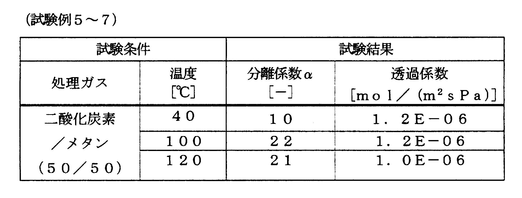
- Test Example 5 The gas separation performance of the zeolite membrane formed in Production Example 1 was evaluated. That is, separation was carried out to selectively permeate carbon dioxide from a 50% / 50% mixture of carbon dioxide / methane. The separation conditions were a temperature of 40 ° C. and a pressure difference of 3 atmospheres before and after the membrane. As a result, the permeability coefficient was 1.2E-0.6 mol / (m 2 spa), and the separation coefficient ⁇ was 10. Test Example 6 The temperature under the test conditions was changed to 100 ° C., and other points were the same as in Test Example 5.
- the permeability coefficient was 1.2E ⁇ 0.6 mol / (m 2 spa), and the separation coefficient ⁇ was 22.
- Test Example 7 The temperature under the test conditions was changed to 120 ° C., and the other points were operated in the same manner as in Test Example 5. As a result, the permeability coefficient was 1.0E-0.6 mol / (m 2 spa), and the separation coefficient ⁇ was 21.
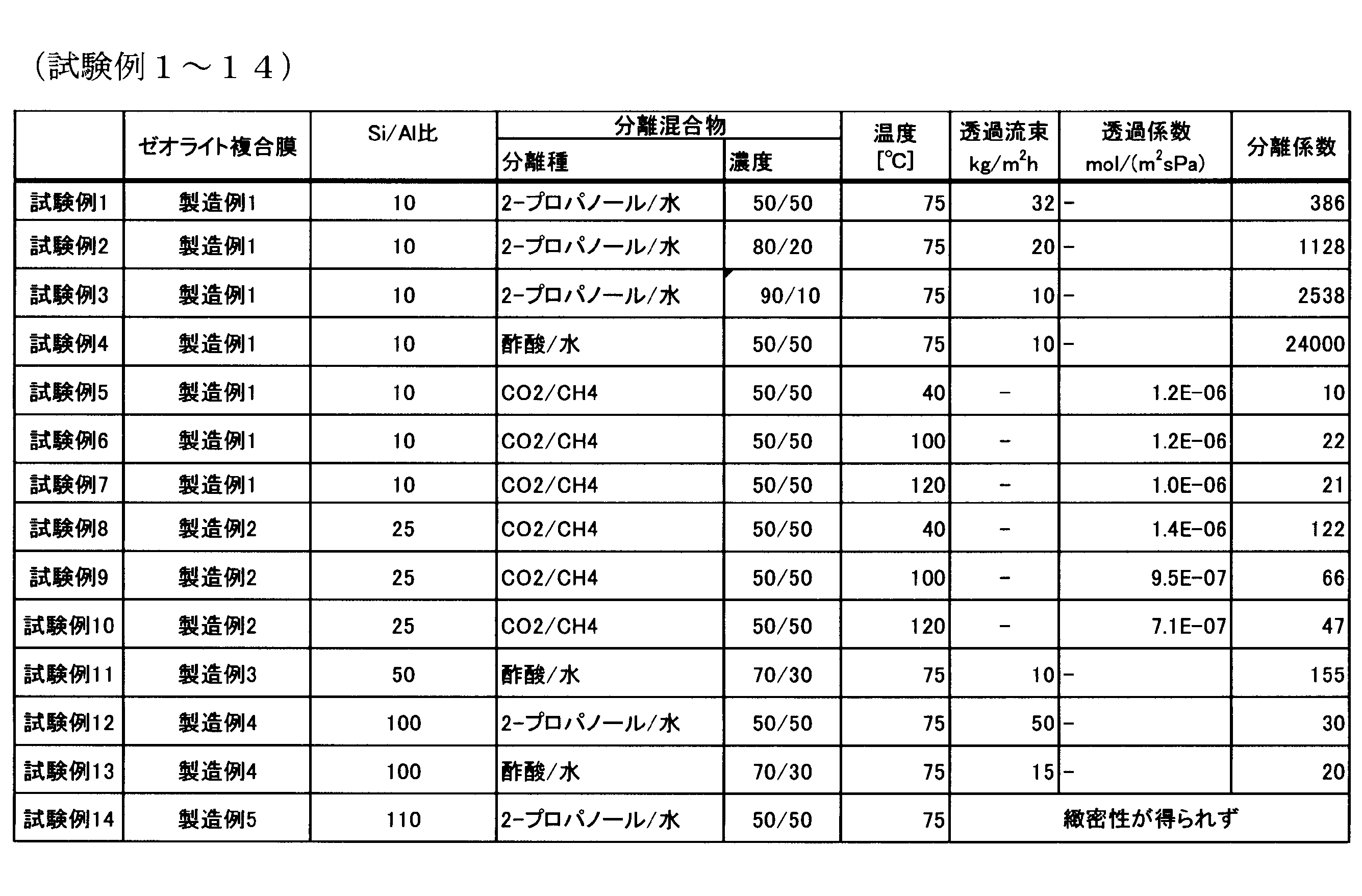
- Test conditions and test results of Test Examples 1 to 4 are shown together in Table 1, and test conditions and test results of Test Examples 5 to 7 are shown together in Table 2. These results show a high transmission rate as compared with Patent Document 1 and show the superiority of the present invention.
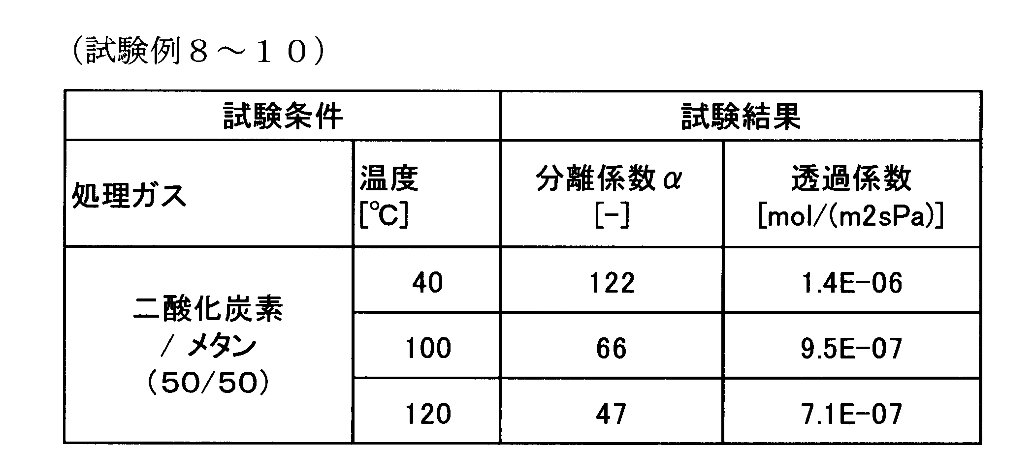
- Test Example 8 The gas separation performance of the zeolite membrane formed in Production Example 2 was evaluated. A separation that selectively permeates carbon dioxide from a 50% / 50% mixture in moles of carbon dioxide / methane was performed. The separation conditions were a temperature of 40 ° C. and a pressure difference of 3 atmospheres before and after the membrane. As a result, the permeability coefficient was 1.4E-0.6 mol / (m 2 spa), and the separation coefficient ⁇ was 122. Test Example 9 The temperature under the test conditions was changed to 100 ° C., and the other points were the same as in Test Example 8.
- the permeability coefficient was 9.5E-0.7 mol / (m 2 spa), and the separation coefficient ⁇ was 66.
- Test Example 10 The temperature under the test conditions was changed to 120 ° C., and the other points were operated in the same manner as in Test Example 8. As a result, the permeability coefficient was 7.1E-0.7 mol / (m 2 spa), and the separation coefficient ⁇ was 47.
- Test Example 11 The separation performance of the zeolite membrane formed in Production Example 3 was evaluated by a pervaporation method. The separation target liquid was changed to a 30% by weight / 70% by weight mixture of water / acetic acid, and the other points were the same as in Test Example 1. As a result, the permeation flux was 10 kg / (m 2 h), and the separation factor was 155. Test Example 12 The separation performance of the zeolite membrane formed in Production Example 4 was evaluated by the pervaporation method. The liquid to be separated was changed to a 50% / 50% by weight mixture of water / 2-propanol, and the other points were the same as in Test Example 1.
- test Example 13 The separation performance of the zeolite membrane formed in Production Example 4 was evaluated by the pervaporation method. The separation target liquid was changed to a 30% by weight / 70% by weight mixture of water / acetic acid, and the other points were the same as in Test Example 1. As a result, the permeation flux was 15 kg / (m 2 h), and the separation factor was 20.
- Test Example 14 The separation performance of the zeolite membrane formed in Production Example 5 was evaluated by a pervaporation method. The liquid to be separated was changed to a 50% / 50% by weight mixture of water / 2-propanol, and the other points were the same as in Test Example 1. As a result, the permeation flux was 90 kg / (m 2 h), and the separation factor was 1. Therefore, a dense film could not be obtained.
Landscapes
- Chemical & Material Sciences (AREA)
- Chemical Kinetics & Catalysis (AREA)
- Inorganic Chemistry (AREA)
- Organic Chemistry (AREA)
- Geology (AREA)
- Life Sciences & Earth Sciences (AREA)
- Engineering & Computer Science (AREA)
- General Life Sciences & Earth Sciences (AREA)
- Analytical Chemistry (AREA)
- Materials Engineering (AREA)
- Oil, Petroleum & Natural Gas (AREA)
- General Chemical & Material Sciences (AREA)
- Crystallography & Structural Chemistry (AREA)
- Manufacturing & Machinery (AREA)
- Separation Using Semi-Permeable Membranes (AREA)
- Silicates, Zeolites, And Molecular Sieves (AREA)
Abstract
Description
(1) 中間層を有する多孔質支持体の中間層上に製膜されたCHA型結晶構造を有するゼオライト膜であって、CHA型ゼオライト粒子のSi/Al(モル比)が9.5~100.5であり、ゼオライト膜表面にX線を照射して得たX線回折パターンにおいて、2θ=18°付近のピーク強度が2θ=21°付近のピーク強度の0.5倍未満、および/または、2θ=10°付近のピーク強度が2θ=21°付近のピーク強度の4倍未満であることを特徴とするゼオライト膜を製造する方法において、
Si元素源、Al元素源、アルカリ源および有機テンプレートを含む水性反応混合物を用いて、水熱合成により、CHA型結晶構造を有するゼオライト膜を多孔質支持体の中間層上に形成するに当たり、Si元素源およびAl元素源として脱アルミニウム処理してないFAU型ゼオライトを用いることを特徴とするゼオライト膜の製造方法。
(2) 前記水熱合成において種結晶を用い、当該種結晶は、Si元素源、Al元素源、アルカリ源および有機テンプレートを含む水性反応混合物を用いる水熱合成においてSi元素源およびAl元素源としてFAU型ゼオライトを用いて調製されることを特徴とする前記(1)に記載のゼオライト膜の製造方法。
(3) CHA型結晶の粒子径が100nm~1μmであることを特徴とする前記(2)に記載のゼオライト膜の製造方法。
(4) 前記(1)~(3)のいずれかに記載の製造方法で得られたゼオライト膜に、分離すべき化合物を含む液体または気体の混合物を接触させて、該混合物から高透過性の物質を透過させて該化合物を分離することを特徴とする分離方法。
(5) 分離すべき化合物を含む混合物が、含水率10重量%以上の2-プロパノールと水の混合物であり、温度75℃、膜前後の圧力差1気圧の条件で分離を行った場合、透過流束が10kg/(m2h)以上、透過液の水濃度が99重量%以上であることを特徴とする前記(4)に記載の分離方法。
(6) 分離すべき化合物を含む混合物が、含水率30重量%以上の酢酸と水の混合物であり、温度75℃、膜前後の圧力差1気圧の条件で分離を行った場合、透過流束が10kg/(m2h)以上、透過液の水濃度が99重量%以上であることを特徴とする前記(4)に記載の分離方法。
(7) 分離すべき化合物を含む混合物が、二酸化炭素の割合が50重量%以上である二酸化炭素と、メタン、アンモニアまたは六フッ化硫黄との混合気体であり、温度40℃、膜前後の圧力差3気圧の条件で分離を行った場合、二酸化炭素の透過係数が1×10⁻⁶mol/(m2sPa)以上であることを特徴とする前記(4)に記載の分離方法。
(8) 分離すべき化合物を含む混合物が、二酸化炭素の割合が50重量%以上である二酸化炭素と、メタン、アンモニアまたは六フッ化硫黄との混合気体であり、温度100~120℃、膜前後の圧力差3気圧の条件で分離を行った場合、二酸化炭素の透過係数が1×10⁻⁷mol/(m2sPa)以上であることを特徴とする前記(4)に記載の分離方法。
[中間層を有する多孔質支持体]
本発明における多孔質支持体は、ゼオライト膜を形成すべき表面に中間層を有する。多孔質支持体は、中間層の上にゼオライトを薄膜として結晶化できるものであれば良く、アルミナ、シリカ、ムライト、ジルコニア、チタニア、ステンレススチールやアルミニウムを代表とする金属あるいは各種合金製の多孔質支持体、陽極酸化膜多孔質支持体などである。多孔質支持体上にゼオライト膜を形成したものを分子ふるい等として利用する場合、(a)ゼオライト膜を強固に担持することができ、(b)圧損ができるだけ小さく、かつ(c)多孔質支持体が十分な自己支持性(機械的強度)を有するという条件を満たすように、多孔質支持体の平均細孔径等を設定するのが好ましい。具体的には、多孔質支持体の平均細孔径は10~50μmであるのが好ましい。中間層を含む多孔質支持体の肉厚は1~3mmであるのが好ましい。中間層の平均細孔径は0.1~1μmであるのが好ましい。1μmより大きい場合は緻密なゼオライト層を形成することが難しい。また、0.1μmより小さい場合は、中間層の物質透過抵抗が大きいため適さない。中間層の厚さは1~50μmであるのが好ましく、1~10μmであるのがより好ましい。また、多孔質支持体の気孔率は20~50%であるのが好ましく、35~40%であるのがより好ましい。
[ゼオライト膜の合成]
本発明による方法では、前述した多孔質支持体の中間層の上に、Si元素源、Al元素源、アルカリ源および有機テンプレートを含む水性反応混合物を用いて、水熱合成により、CHA型結晶構造を有するゼオライト膜を形成する。
水熱合成において使用する種結晶としては、Si元素源およびAl元素源として脱アルミニウム処理してないFAU型ゼオライトを用いて水熱合成により調製したCHA結晶を用いることが好ましい。
種結晶の粒子径は小さい方が望ましく、必要に応じて粉砕して用いても良い。支持体の中間層の上に種結晶を付着させるには、例えば、種結晶を水などの溶媒に分散させてその分散液に支持体を浸けて種結晶を付着させるディップ法や、種結晶を水などの溶媒と混合してスラリー状にしたものを支持体表面上に塗り込む方法などを用いることができる。種結晶の大きさは、好ましくは100nm~1μm、より好ましくは100~800nmである。種結晶が1μmより大きい場合、支持体中間層の細孔径との兼ね合いにより、緻密なゼオライト層を形成できない。なお、種結晶の粒子径は大塚電子株式会社製の粒子径測定器(商品名、FPAR-1000)を用いて測定することができる。
水熱処理により、多孔質支持体の表面において、FAU型ゼオライト粉末は一旦、分解した後、種結晶を起点として、種結晶と同じ結晶構造(すなわち、CHA構造)を有するゼオライトの核を形成する。あるいは、FAU型ゼオライトが分解した後、有機テンプレートの作用によって、CHA構造を有するゼオライトの核を形成する。形成された核から、生成ゼオライトの結晶が成長する。FAUとCHAの構造ユニットが同じであるため、FAUの構造の一部がそのままCHAの結晶化に寄与する。そのため、結晶構造内に欠陥が生じにくい。
さらに、本発明では、脱アルミニウム処理を行っていないFAU型ゼオライトを用いているため、FAUの結晶性が高く、よりFAUの構造を活かしたCHA膜の合成が可能となる。
[ゼオライト膜]
本発明の製造方法により、中間層を有する多孔質支持体の中間層上に製膜されたCHA型結晶構造を有するゼオライト膜は、CHA型ゼオライト粒子のSi/Al(モル比)が9.5~100.5、好ましくは10~100、より好ましくは20~80であり、ゼオライト膜表面にX線を照射して得たX線回折パターンにおいて、2θ=18°付近のピーク強度が2θ=21°付近のピーク強度の0.5倍未満、好ましくは0.4未満、より好ましくは0.35未満、最も好ましくは0.25未満であり、2θ=10°付近のピーク強度が2θ=21°付近のピーク強度の4倍未満、好ましくは3未満、より好ましくは2.5未満、最も好ましくは0.2未満あるものである。(2θ=18°付近のピーク強度)/(2θ=21°付近のピーク強度)の下限は限定されないが、通常は0.1である。(2θ=10°付近のピーク強度)/(2θ=21°付近のピーク強度)の下限も限定されないが、通常は1である。
本明細書および特許請求の範囲を通して、2θ=18°付近のピークとは基材に由来しないピークのうち18°±0.6°の範囲に存在するピークのうち最大のものを指すこととし、2θ=21°付近のピークとは基材に由来しないピークのうち21°±0.6°の範囲に存在するピークで最大のものを指すこととし、2θ=10°付近のピークとは基材に由来しないピークのうち10°±0.6°の範囲に存在するピークのうち最大のものを指すこととする。
[分離方法]
本発明の分離方法において、本発明によるゼオライト膜を用いて、常法に従って分離操作を行うことができる。パーベーパレーション法(浸透気化法)、ベーパーパーミエーション法(蒸気透過法)と呼ばれる分離・濃縮方法が、本発明によるゼオライト膜を用いて好適に実施できる。例えば、水と有機化合物の混合物の場合、通常水がゼオライト膜に対する透過性が高いので、混合物から水が分離され、有機化合物は元の混合物中で濃縮される。
[実施例1]
<CHA型ゼオライト膜の形成>
下記の製造例1において、CHA型ゼオライトを無機多孔質支持体の中間層の上に直接水熱合成することでCHA型ゼオライト膜を形成した。
製造例1
表面に中間層(厚み約50μm、平均細孔径0.8μm)を有する円柱状のアルミナ支持体(日立造船社製、直径16mm、長さ60mm、平均細孔径10μm)を用意し、その中間層の表面に種結晶としてCHA型ゼオライトを25g/m2付着させた。中間層の平均細孔径の測定は、JIS K 3832に準拠して行った。
最後に、有機テンプレートを除去するため、電気炉にて500℃で10時間焼成を行った。
得られたゼオライト膜の電子顕微鏡像を図1に示す。図1の(a)は膜の表面、(b)は膜の断面である。ゼオライト膜の表面は、10~100nmの微粒子で隙間無く覆われており、その厚みは2~3μmであった。
得られたX線回折パターンを図2に示す。このX線回折パターンから、この膜がCHA型ゼオライトで構成されていることを確認した。X線回折パターンにおいて、2θ=18°付近のピーク強度は2θ=21°付近のピーク強度の0.3倍であり、2θ=10°付近のピーク強度は2θ=21°付近のピーク強度の2.7倍であることが分かった。
製造例2 (Si/Al比の影響=25)
表面に中間層(厚み約50μm、平均細孔径0.8μm)を有する円柱状のアルミナ支持体(日立造船社製、直径16mm、長さ60mm、平均細孔径10μm)を用意し、その中間層の表面に種結晶としてCHA型ゼオライトを25g/m2付着させた。
以降の工程は製造例1と同様の方法で行った。
得られたゼオライト膜のX線回折測定の結果は、製造例1で得られたゼオライト膜と同じX線回折パターンを示した。
製造例3 (Si/Al比の影響=50)
表面に中間層(厚み約50μm、平均細孔径0.8μm)を有する円柱状のアルミナ支持体(日立造船社製、直径16mm、長さ60mm、平均細孔径10μm)を用意し、その中間層の表面に種結晶としてCHA型ゼオライトを25g/m2付着させた。
以降の工程は製造例1と同様の方法で行った。
得られたゼオライト膜のX線回折測定の結果は、製造例1で得られたゼオライト膜と同じX線回折パターンを示した。
製造例4 (Si/Al比の影響=100)
表面に中間層(厚み約50μm、平均細孔径0.8μm)を有する円柱状のアルミナ支持体(日立造船社製、直径16mm、長さ60mm、平均細孔径10μm)を用意し、その中間層の表面に種結晶としてCHA型ゼオライトを25g/m2付着させた。
以降の工程は製造例1と同様の方法で行った。
得られたゼオライト膜のX線回折測定の結果は、製造例1で得られたゼオライト膜と同じX線回折パターンを示した。
製造例5 (Si/Al比の影響=110)
表面に中間層(厚み約50μm、平均細孔径0.8μm)を有する円柱状のアルミナ支持体(日立造船社製、直径16mm、長さ60mm、平均細孔径10μm)を用意し、その中間層の表面に種結晶としてCHA型ゼオライトを25g/m2付着させた。
以降の工程は製造例1と同様の方法で行った。
得られたゼオライト膜のX線回折測定の結果は、製造例1で得られたゼオライト膜と同じX線回折パターンを示した。
<分離性能の測定>
試験例1
上記製造例1で形成したゼオライト膜の分離性能を、パーベーパレーション法で評価した。すなわち、水/2-プロパノールの50重量%/50重量%の混合物から水を選択的に透過させる分離を行った。分離条件は、温度75℃、膜前後の圧力差1気圧とした。その結果、透過流束は32kg/(m2h)となり、分離係数α(水/2-プロパノール
)は386で、透過液の水濃度は99.7重量%であった。
試験例2
分離対象液を水/2-プロパノールの20重量%/80重量%の混合物に変え、その他の点は試験例1と同様に操作した。その結果、透過流束は20kg/(m2h)となり、分離係数α(水/2-プロパノール)は1128で、透過液の水濃度は99.6重量%であった。
試験例3
分離対象液を水/2-プロパノールの10重量%/90重量%の混合物に変え、その他の点は試験例1と同様に操作した。その結果、透過流束は10kg/(m2h)となり、透過液の水濃度は99.6重量%であった。
試験例4
分離対象液を水/酢酸の50重量%/50重量%の混合物に変え、その他の点は試験例1と同様に操作した。その結果、透過流束は10kg/(m2h)となり、透過液の水濃度は99.9重量%であった。
試験例5
上記製造例1で形成したゼオライト膜のガス分離性能を評価した。すなわち、二酸化炭素/メタンのモルで50%/50%の混合物から二酸化炭素を選択的に透過させる分離を行った。分離条件は、温度40℃、膜前後の圧力差3気圧とした。その結果、透過係数は1.2E-0.6mol/(m2sPa)となり、分離係数αは10であった。
試験例6
試験条件における温度を100℃に変え、その他の点は試験例5と同様に操作した。その結果、透過係数は1.2E-0.6mol/(m2sPa)となり、分離係数αは22であった。
試験例7
試験条件における温度を120℃に変え、その他の点は試験例5と同様に操作した。その結果、透過係数は1.0E-0.6mol/(m2sPa)となり、分離係数αは21であった。

試験例8
上記製造例2で形成したゼオライト膜のガス分離性能を評価した。二酸化炭素/メタンのモルで50%/50%の混合物から二酸化炭素を選択的に透過させる分離を行った。分離条件は、温度40℃、膜前後の圧力差3気圧とした。その結果、透過係数は1.4E-0.6mol/(m2sPa)となり、分離係数αは122であった。
試験例9
試験条件における温度を100℃に変え、その他の点は試験例8と同様に操作した。その結果、透過係数は9.5E-0.7mol/(m2sPa)となり、分離係数αは66であった。
試験例10
試験条件における温度を120℃に変え、その他の点は試験例8と同様に操作した。その結果、透過係数は7.1E-0.7mol/(m2sPa)となり、分離係数αは47であった。
試験例11
上記製造例3で形成したゼオライト膜の分離性能を、パーベーパレーション法で評価した。分離対象液を水/酢酸の30重量%/70重量%の混合物に変え、その他の点は試験例1と同様に操作した。その結果、透過流束は10kg/(m2h)となり、分離係数は155であった。
試験例12
上記製造例4で形成したゼオライト膜の分離性能をパーベーパレーション法で評価した。分離対象液を水/2―プロパノールの50重量%/50重量%の混合物に変え、その他の点は試験例1と同様に操作した。その結果、透過流束は50kg/(m2h)となり、分離係数は30であった。
試験例13
上記製造例4で形成したゼオライト膜の分離性能をパーベーパレーション法で評価した。分離対象液を水/酢酸の30重量%/70重量%の混合物に変え、その他の点は試験例1と同様に操作した。その結果、透過流束は15kg/(m2h)となり、分離係数は20であった。
試験例14
上記製造例5で形成したゼオライト膜の分離性能をパーベーパレーション法で評価した。分離対象液を水/2-プロパノールの50重量%/50重量%の混合物に変え、その他の点は試験例1と同様に操作した。その結果、透過流束は90kg/(m2h)となり、分離係数は1であった。よって、緻密な膜は得られなかった。
Claims (8)
- 中間層を有する多孔質支持体の中間層上に製膜されたCHA型結晶構造を有するゼオライト膜であって、CHA型ゼオライト粒子のSi/Al(モル比)が9.5~100.5であり、ゼオライト膜表面にX線を照射して得たX線回折パターンにおいて、2θ=18°付近のピーク強度が2θ=21°付近のピーク強度の0.5倍未満、および/または、2θ=10°付近のピーク強度が2θ=21°付近のピーク強度の4倍未満であることを特徴とするゼオライト膜を製造する方法において、
Si元素源、Al元素源、アルカリ源および有機テンプレートを含む水性反応混合物を用いて、水熱合成により、CHA型結晶構造を有するゼオライト膜を多孔質支持体の中間層上に形成するに当たり、Si元素源およびAl元素源として脱アルミニウム処理してないFAU型ゼオライトを用いることを特徴とするゼオライト膜の製造方法。 - 前記水熱合成において種結晶を用い、当該種結晶は、Si元素源、Al元素源、アルカリ源および有機テンプレートを含む水性反応混合物を用いる水熱合成においてSi元素源およびAl元素源としてFAU型ゼオライトを用いて調製されることを特徴とする請求項1に記載のゼオライト膜の製造方法。
- CHA型結晶の粒子径が100nm~1μmであることを特徴とする請求項2に記載のゼオライト膜の製造方法。
- 請求項1~3のいずれかに記載の製造方法で得られ
たゼオライト膜に、分離すべき化合物を含む液体または気体の混合物を接触させて、該混合物から高透過性の物質を透過させて該化合物を分離することを特徴とする分離方法。 - 分離すべき化合物を含む混合物が、含水率10重量%以上の2-プロパノールと水の混合物であり、温度75℃、膜前後の圧力差1気圧の条件で分離を行った場合、透過流束が10kg/(m2h)以上、透過液の水濃度が99重量%以上であることを特徴とする請求項4に記載の分離方法。
- 分離すべき化合物を含む混合物が、含水率30重量%以上の酢酸と水の混合物であり、温度75℃、膜前後の圧力差1気圧の条件で分離を行った場合、透過流束が10kg/(m2h)以上、透過液の水濃度が99重量%以上であることを特徴とする請求項4に記載の分離方法。
- 分離すべき化合物を含む混合物が、二酸化炭素の割合が50重量%以上である二酸化炭素と、メタン、アンモニアまたは六フッ化硫黄との混合気体であり、温度40℃、膜前後の圧力差3気圧の条件で分離を行った場合、二酸化炭素の透過係数が1×10⁻⁶mol/(m2sPa)以上であることを特徴とする請求項4に記載の分離方法。
- 分離すべき化合物を含む混合物が、二酸化炭素の割合が50重量%以上である二酸化炭素と、メタン、アンモニアまたは六フッ化硫黄との混合気体であり、温度100~120℃、膜前後の圧力差3気圧の条件で分離を行った場合、二酸化炭素の透過係数が1×10⁻⁷mol/(m2sPa)以上であることを特徴とする請求項4に記載の分離方法。
Priority Applications (5)
| Application Number | Priority Date | Filing Date | Title |
|---|---|---|---|
| MYPI2016704890A MY183277A (en) | 2014-07-10 | 2015-07-06 | Zeolite membrane, production method therefor, and separation method using same |
| EP15818543.9A EP3167953B1 (en) | 2014-07-10 | 2015-07-06 | Zeolite membrane, production method therefor, and separation method using same |
| CN201580035833.4A CN106573204B (zh) | 2014-07-10 | 2015-07-06 | 沸石膜、其制备方法及使用了该沸石膜的分离方法 |
| US15/325,130 US10639594B2 (en) | 2014-07-10 | 2015-07-06 | Zeolite membrane, production method therefor, and separation method using same |
| JP2016532919A JP6373381B2 (ja) | 2014-07-10 | 2015-07-06 | ゼオライト膜、その製造方法およびこれを用いた分離方法 |
Applications Claiming Priority (2)
| Application Number | Priority Date | Filing Date | Title |
|---|---|---|---|
| JP2014142386 | 2014-07-10 | ||
| JP2014-142386 | 2014-07-10 |
Publications (1)
| Publication Number | Publication Date |
|---|---|
| WO2016006564A1 true WO2016006564A1 (ja) | 2016-01-14 |
Family
ID=55064199
Family Applications (1)
| Application Number | Title | Priority Date | Filing Date |
|---|---|---|---|
| PCT/JP2015/069394 Ceased WO2016006564A1 (ja) | 2014-07-10 | 2015-07-06 | ゼオライト膜、その製造方法およびこれを用いた分離方法 |
Country Status (6)
| Country | Link |
|---|---|
| US (1) | US10639594B2 (ja) |
| EP (1) | EP3167953B1 (ja) |
| JP (1) | JP6373381B2 (ja) |
| CN (1) | CN106573204B (ja) |
| MY (1) | MY183277A (ja) |
| WO (1) | WO2016006564A1 (ja) |
Cited By (15)
| Publication number | Priority date | Publication date | Assignee | Title |
|---|---|---|---|---|
| JP2017148741A (ja) * | 2016-02-25 | 2017-08-31 | 日立造船株式会社 | ゼオライト膜複合体の再生方法 |
| JPWO2017142056A1 (ja) * | 2016-02-19 | 2018-12-13 | 日立造船株式会社 | ゼオライト分離膜およびその製造方法 |
| JP2019181456A (ja) * | 2018-03-30 | 2019-10-24 | 日本碍子株式会社 | ゼオライト膜複合体、ゼオライト膜複合体の製造方法、および、分離方法 |
| US20200122096A1 (en) * | 2017-06-07 | 2020-04-23 | Ngk Insulators, Ltd. | Dehydration method and dehydration apparatus |
| DE102019134983A1 (de) | 2018-12-28 | 2020-07-02 | Korea University Research And Business Foundation | CHA-Zeolithmembran und Verfahren zu ihrer Herstellung |
| WO2020195369A1 (ja) * | 2019-03-25 | 2020-10-01 | 日本碍子株式会社 | ゼオライト膜複合体の製造方法およびゼオライト膜複合体 |
| JP2020182901A (ja) * | 2019-05-08 | 2020-11-12 | 日立造船株式会社 | ゼオライト膜複合体及びその製造方法 |
| JP2020196008A (ja) * | 2019-05-29 | 2020-12-10 | 独立行政法人石油天然ガス・金属鉱物資源機構 | 二酸化炭素を含む混合気体の分離又は濃縮方法 |
| JP2021028054A (ja) * | 2019-08-09 | 2021-02-25 | 三菱ケミカル株式会社 | ゼオライト膜複合体の再生方法 |
| WO2021186959A1 (ja) * | 2020-03-18 | 2021-09-23 | 日本碍子株式会社 | ガス分離方法およびゼオライト膜 |
| JPWO2021240917A1 (ja) * | 2020-05-25 | 2021-12-02 | ||
| JP2021191577A (ja) * | 2018-01-16 | 2021-12-16 | 日本碍子株式会社 | 分離方法 |
| JP2022074397A (ja) * | 2020-11-04 | 2022-05-18 | 日立造船株式会社 | 分離部材および分離方法 |
| JP2022532745A (ja) * | 2019-05-15 | 2022-07-19 | ビーエーエスエフ ソシエタス・ヨーロピア | Cha-aftゼオライト連晶coe-10の製造方法及び不均一系触媒におけるその使用 |
| JP2022546068A (ja) * | 2019-08-29 | 2022-11-02 | シェブロン ユー.エス.エー. インコーポレイテッド | Sew骨格型のアルミニウム含有モレキュラーシーブの合成 |
Families Citing this family (14)
| Publication number | Priority date | Publication date | Assignee | Title |
|---|---|---|---|---|
| CN114146576A (zh) * | 2014-11-25 | 2022-03-08 | 三菱化学株式会社 | 多孔支持体-沸石膜复合体以及多孔支持体-沸石膜复合体的制造方法 |
| RU2708861C2 (ru) | 2015-03-24 | 2019-12-11 | Арстрома Ко., Лтд. | Устройство разделения текучих сред, включающее мембрану для разделения текучих сред, и мембранный модуль для разделения текучих сред |
| WO2019159782A1 (ja) * | 2018-02-15 | 2019-08-22 | 日本碍子株式会社 | ガス分離装置、ガス分離方法およびガス分離膜 |
| KR102715371B1 (ko) | 2018-03-21 | 2024-10-14 | 바스프 모바일 에미션스 카탈리스츠 엘엘씨 | Cha 제올라이트 물질 및 관련 합성 방법 |
| WO2019187640A1 (ja) * | 2018-03-30 | 2019-10-03 | 日本碍子株式会社 | ゼオライト膜複合体、ゼオライト膜複合体の製造方法、および、分離方法 |
| JP7590869B2 (ja) | 2018-09-28 | 2024-11-27 | 日本碍子株式会社 | 支持体、ゼオライト膜複合体、ゼオライト膜複合体の製造方法、および、分離方法 |
| WO2020071107A1 (ja) | 2018-10-04 | 2020-04-09 | 日本碍子株式会社 | ガス分離方法およびガス分離装置 |
| MX2021010659A (es) | 2019-03-04 | 2021-09-28 | Ngk Insulators Ltd | Compuesto de membrana de zeolita, metodo para producir de compuesto de membrana de zeolita y metodo de separacion. |
| CN110028081A (zh) * | 2019-04-19 | 2019-07-19 | 大连理工大学 | 一种合成纳米级多级孔ssz-13分子筛的方法 |
| WO2020255867A1 (ja) * | 2019-06-17 | 2020-12-24 | 日本碍子株式会社 | ゼオライト膜複合体、ゼオライト膜複合体の製造方法、分離装置、膜型反応装置および分離方法 |
| CN114007725A (zh) * | 2019-06-27 | 2022-02-01 | 公益财团法人地球环境产业技术研究机构 | 沸石膜复合体及其制造方法、以及流体分离方法 |
| CN111530302B (zh) * | 2020-04-30 | 2022-08-09 | 上海工程技术大学 | 一种全硅和高硅cha分子筛膜的可控合成方法 |
| WO2022014469A1 (ja) * | 2020-07-13 | 2022-01-20 | 日本碍子株式会社 | 分離システム |
| CN118984809A (zh) * | 2022-05-17 | 2024-11-19 | 庄信万丰股份有限公司 | Cha型沸石和合成所述沸石的方法 |
Citations (5)
| Publication number | Priority date | Publication date | Assignee | Title |
|---|---|---|---|---|
| WO2010098473A1 (ja) * | 2009-02-27 | 2010-09-02 | 三菱化学株式会社 | 無機多孔質支持体-ゼオライト膜複合体、その製造方法およびそれを用いた分離方法 |
| JP2010532259A (ja) * | 2007-06-29 | 2010-10-07 | コーニング インコーポレイテッド | ゼオライト膜構造体及びゼオライト膜構造体の製造方法 |
| JP2012050930A (ja) * | 2010-09-01 | 2012-03-15 | Hitachi Zosen Corp | ゼオライト分離膜、およびその製造方法 |
| WO2012046545A1 (ja) * | 2010-10-06 | 2012-04-12 | 日立造船株式会社 | 複合ゼオライト膜、およびその製造方法 |
| WO2013125660A1 (ja) * | 2012-02-24 | 2013-08-29 | 三菱化学株式会社 | ゼオライト膜複合体 |
Family Cites Families (3)
| Publication number | Priority date | Publication date | Assignee | Title |
|---|---|---|---|---|
| JP5527107B2 (ja) | 2009-11-11 | 2014-06-18 | 三菱化学株式会社 | 含水有機化合物の分離方法および分離装置 |
| JP5533438B2 (ja) | 2010-08-25 | 2014-06-25 | 三菱化学株式会社 | 含水有機化合物の脱水濃縮装置 |
| EP3132842A4 (en) * | 2014-04-18 | 2017-04-05 | Mitsubishi Chemical Corporation | (porous support)-(zeolite film) complex, and method for producing (porous support)-(zeolite film) complex |
-
2015
- 2015-07-06 CN CN201580035833.4A patent/CN106573204B/zh active Active
- 2015-07-06 JP JP2016532919A patent/JP6373381B2/ja active Active
- 2015-07-06 EP EP15818543.9A patent/EP3167953B1/en active Active
- 2015-07-06 WO PCT/JP2015/069394 patent/WO2016006564A1/ja not_active Ceased
- 2015-07-06 MY MYPI2016704890A patent/MY183277A/en unknown
- 2015-07-06 US US15/325,130 patent/US10639594B2/en active Active
Patent Citations (5)
| Publication number | Priority date | Publication date | Assignee | Title |
|---|---|---|---|---|
| JP2010532259A (ja) * | 2007-06-29 | 2010-10-07 | コーニング インコーポレイテッド | ゼオライト膜構造体及びゼオライト膜構造体の製造方法 |
| WO2010098473A1 (ja) * | 2009-02-27 | 2010-09-02 | 三菱化学株式会社 | 無機多孔質支持体-ゼオライト膜複合体、その製造方法およびそれを用いた分離方法 |
| JP2012050930A (ja) * | 2010-09-01 | 2012-03-15 | Hitachi Zosen Corp | ゼオライト分離膜、およびその製造方法 |
| WO2012046545A1 (ja) * | 2010-10-06 | 2012-04-12 | 日立造船株式会社 | 複合ゼオライト膜、およびその製造方法 |
| WO2013125660A1 (ja) * | 2012-02-24 | 2013-08-29 | 三菱化学株式会社 | ゼオライト膜複合体 |
Non-Patent Citations (2)
| Title |
|---|
| HASEGAWA, YASUHISA ET AL.: "Preparation of High-Silica Chabazite Membrane", MEMBRANE, vol. 39, no. 1, pages 56 - 60, XP008183720 * |
| ITAKURA, MASAYA ET AL.: "Synthesis of high- silica CHA type zeolite by interzeolite conversion of FAU type zeolite in the presence of seed crystals", MICROPOROUS AND MESOPOROUS MATERIALS, vol. 144, 24 March 2011 (2011-03-24), pages 91 - 96, XP028100122, DOI: doi:10.1016/j.micromeso.2011.03.041 * |
Cited By (32)
| Publication number | Priority date | Publication date | Assignee | Title |
|---|---|---|---|---|
| JPWO2017142056A1 (ja) * | 2016-02-19 | 2018-12-13 | 日立造船株式会社 | ゼオライト分離膜およびその製造方法 |
| US11666867B2 (en) | 2016-02-19 | 2023-06-06 | Hitachi Zosen Corporation | Zeolite separation membrane and production method therefor |
| JP2017148741A (ja) * | 2016-02-25 | 2017-08-31 | 日立造船株式会社 | ゼオライト膜複合体の再生方法 |
| US20200122096A1 (en) * | 2017-06-07 | 2020-04-23 | Ngk Insulators, Ltd. | Dehydration method and dehydration apparatus |
| US12138598B2 (en) * | 2017-06-07 | 2024-11-12 | Ngk Insulators, Ltd. | Dehydration method and dehydration apparatus providing increased water permeation |
| JP2021191577A (ja) * | 2018-01-16 | 2021-12-16 | 日本碍子株式会社 | 分離方法 |
| JP2019181456A (ja) * | 2018-03-30 | 2019-10-24 | 日本碍子株式会社 | ゼオライト膜複合体、ゼオライト膜複合体の製造方法、および、分離方法 |
| JP7220087B2 (ja) | 2018-03-30 | 2023-02-09 | 日本碍子株式会社 | ゼオライト膜複合体、ゼオライト膜複合体の製造方法、および、分離方法 |
| DE102019134983A1 (de) | 2018-12-28 | 2020-07-02 | Korea University Research And Business Foundation | CHA-Zeolithmembran und Verfahren zu ihrer Herstellung |
| US12036517B2 (en) | 2018-12-28 | 2024-07-16 | Korea University Research And Business Foundation | CHA zeolite membrane and method of preparing the same |
| US11458441B2 (en) | 2018-12-28 | 2022-10-04 | Korea University Research And Business Foundation | CHA zeolite membrane and method of preparing the same |
| JPWO2020195369A1 (ja) * | 2019-03-25 | 2021-12-02 | 日本碍子株式会社 | ゼオライト膜複合体の製造方法およびゼオライト膜複合体 |
| WO2020195369A1 (ja) * | 2019-03-25 | 2020-10-01 | 日本碍子株式会社 | ゼオライト膜複合体の製造方法およびゼオライト膜複合体 |
| US11400421B2 (en) | 2019-03-25 | 2022-08-02 | Ngk Insulators, Ltd. | Method of producing zeolite membrane complex and zeolite membrane complex |
| JP7257244B2 (ja) | 2019-05-08 | 2023-04-13 | 日立造船株式会社 | ゼオライト膜複合体及びその製造方法 |
| JP2020182901A (ja) * | 2019-05-08 | 2020-11-12 | 日立造船株式会社 | ゼオライト膜複合体及びその製造方法 |
| JP7648541B2 (ja) | 2019-05-15 | 2025-03-18 | ビーエーエスエフ ソシエタス・ヨーロピア | Cha-aftゼオライト連晶coe-10の製造方法及び不均一系触媒におけるその使用 |
| JP2022532745A (ja) * | 2019-05-15 | 2022-07-19 | ビーエーエスエフ ソシエタス・ヨーロピア | Cha-aftゼオライト連晶coe-10の製造方法及び不均一系触媒におけるその使用 |
| US12264076B2 (en) | 2019-05-15 | 2025-04-01 | Basf Mobile Emissions Catalysts Llc | Process for the production of the CHA-AFT zeolite intergrowth COE-10 and use thereof in heterogeneous catalysis |
| JP2024169593A (ja) * | 2019-05-29 | 2024-12-05 | 三菱ケミカル株式会社 | 二酸化炭素を含む混合気体の分離又は濃縮方法 |
| JP2020196008A (ja) * | 2019-05-29 | 2020-12-10 | 独立行政法人石油天然ガス・金属鉱物資源機構 | 二酸化炭素を含む混合気体の分離又は濃縮方法 |
| JP2021028054A (ja) * | 2019-08-09 | 2021-02-25 | 三菱ケミカル株式会社 | ゼオライト膜複合体の再生方法 |
| JP7358827B2 (ja) | 2019-08-09 | 2023-10-11 | 三菱ケミカル株式会社 | ゼオライト膜複合体の再生方法 |
| JP7513701B2 (ja) | 2019-08-29 | 2024-07-09 | シェブロン ユー.エス.エー. インコーポレイテッド | Sew骨格型のアルミニウム含有モレキュラーシーブの合成 |
| JP2022546068A (ja) * | 2019-08-29 | 2022-11-02 | シェブロン ユー.エス.エー. インコーポレイテッド | Sew骨格型のアルミニウム含有モレキュラーシーブの合成 |
| WO2021186959A1 (ja) * | 2020-03-18 | 2021-09-23 | 日本碍子株式会社 | ガス分離方法およびゼオライト膜 |
| US12458949B2 (en) | 2020-03-18 | 2025-11-04 | Ngk Insulators, Ltd. | Gas separation method and zeolite membrane |
| JP7374320B2 (ja) | 2020-05-25 | 2023-11-06 | 日本碍子株式会社 | 分離膜複合体、分離膜複合体の製造方法および分離方法 |
| WO2021240917A1 (ja) * | 2020-05-25 | 2021-12-02 | 日本碍子株式会社 | 分離膜複合体、分離膜複合体の製造方法および分離方法 |
| JPWO2021240917A1 (ja) * | 2020-05-25 | 2021-12-02 | ||
| US12611634B2 (en) | 2020-05-25 | 2026-04-28 | Ngk Insulators, Ltd. | Separation membrane complex, method of producing separation membrane complex, and separation method |
| JP2022074397A (ja) * | 2020-11-04 | 2022-05-18 | 日立造船株式会社 | 分離部材および分離方法 |
Also Published As
| Publication number | Publication date |
|---|---|
| EP3167953B1 (en) | 2020-09-02 |
| JPWO2016006564A1 (ja) | 2017-06-08 |
| JP6373381B2 (ja) | 2018-08-15 |
| EP3167953A4 (en) | 2017-07-12 |
| US10639594B2 (en) | 2020-05-05 |
| MY183277A (en) | 2021-02-18 |
| CN106573204B (zh) | 2019-12-06 |
| EP3167953A1 (en) | 2017-05-17 |
| US20170189862A1 (en) | 2017-07-06 |
| CN106573204A (zh) | 2017-04-19 |
Similar Documents
| Publication | Publication Date | Title |
|---|---|---|
| JP6373381B2 (ja) | ゼオライト膜、その製造方法およびこれを用いた分離方法 | |
| US11666867B2 (en) | Zeolite separation membrane and production method therefor | |
| JP5569901B2 (ja) | ゼオライト膜、分離膜モジュール及びその製造方法 | |
| JP5324067B2 (ja) | ゼオライト膜の製造方法 | |
| CN106795075B (zh) | 高浓度醇的制造方法 | |
| JP6171151B2 (ja) | ゼオライト膜およびその製造方法 | |
| JP5087644B2 (ja) | Zsm−5型ゼオライト膜の製造方法 | |
| CN109224879B (zh) | 一种cha分子筛膜的制备方法 | |
| WO2010037690A1 (de) | Templatfreie clathrasile und clathrasil-membranen | |
| JP6785483B2 (ja) | ゼオライト薄膜を有する複合膜およびその製造方法 | |
| JP5051815B2 (ja) | マーリノアイト型ゼオライト複合膜及びその製造方法 | |
| JP5051816B2 (ja) | フィリップサイト型ゼオライト複合膜及びその製造方法 | |
| JP2006247599A (ja) | Zsm−5型ゼオライト膜の製造方法 | |
| JP2017018848A (ja) | ゼオライト膜を用いたエチレンアミンの脱水濃縮方法 | |
| JP4599144B2 (ja) | マーリノアイト型ゼオライト膜及びその製造方法 | |
| JP4990193B2 (ja) | Mfi型ゼオライト膜配設体、及びガス分離方法 | |
| JP6476021B2 (ja) | ゼオライト膜およびゼオライト粉末の製造方法 | |
| KR20200119273A (ko) | Ti를 포함하고 골격체형 CHA를 갖는 제올라이트 물질의 제조 방법 | |
| JP2006176399A (ja) | フィリップサイト型ゼオライト膜及びその製造方法 | |
| Zhang et al. | Preparation of ZnAPO-34 films on alumina substrates |
Legal Events
| Date | Code | Title | Description |
|---|---|---|---|
| 121 | Ep: the epo has been informed by wipo that ep was designated in this application |
Ref document number: 15818543 Country of ref document: EP Kind code of ref document: A1 |
|
| ENP | Entry into the national phase |
Ref document number: 2016532919 Country of ref document: JP Kind code of ref document: A |
|
| NENP | Non-entry into the national phase |
Ref country code: DE |
|
| WWE | Wipo information: entry into national phase |
Ref document number: 15325130 Country of ref document: US |
|
| REEP | Request for entry into the european phase |
Ref document number: 2015818543 Country of ref document: EP |
|
| WWE | Wipo information: entry into national phase |
Ref document number: 2015818543 Country of ref document: EP |