WO2015194678A1 - Matériau en poudre destiné à être utilisé en modelage de poudre en strates et procédé de modelage de poudre en strates l'utilisant - Google Patents
Matériau en poudre destiné à être utilisé en modelage de poudre en strates et procédé de modelage de poudre en strates l'utilisant Download PDFInfo
- Publication number
- WO2015194678A1 WO2015194678A1 PCT/JP2015/067933 JP2015067933W WO2015194678A1 WO 2015194678 A1 WO2015194678 A1 WO 2015194678A1 JP 2015067933 W JP2015067933 W JP 2015067933W WO 2015194678 A1 WO2015194678 A1 WO 2015194678A1
- Authority
- WO
- WIPO (PCT)
- Prior art keywords
- particles
- powder material
- powder
- average particle
- particle diameter
- Prior art date
Links
Images
Classifications
-
- B—PERFORMING OPERATIONS; TRANSPORTING
- B22—CASTING; POWDER METALLURGY
- B22F—WORKING METALLIC POWDER; MANUFACTURE OF ARTICLES FROM METALLIC POWDER; MAKING METALLIC POWDER; APPARATUS OR DEVICES SPECIALLY ADAPTED FOR METALLIC POWDER
- B22F9/00—Making metallic powder or suspensions thereof
- B22F9/02—Making metallic powder or suspensions thereof using physical processes
- B22F9/026—Spray drying of solutions or suspensions
-
- B—PERFORMING OPERATIONS; TRANSPORTING
- B22—CASTING; POWDER METALLURGY
- B22F—WORKING METALLIC POWDER; MANUFACTURE OF ARTICLES FROM METALLIC POWDER; MAKING METALLIC POWDER; APPARATUS OR DEVICES SPECIALLY ADAPTED FOR METALLIC POWDER
- B22F1/00—Metallic powder; Treatment of metallic powder, e.g. to facilitate working or to improve properties
- B22F1/05—Metallic powder characterised by the size or surface area of the particles
- B22F1/052—Metallic powder characterised by the size or surface area of the particles characterised by a mixture of particles of different sizes or by the particle size distribution
-
- B—PERFORMING OPERATIONS; TRANSPORTING
- B22—CASTING; POWDER METALLURGY
- B22F—WORKING METALLIC POWDER; MANUFACTURE OF ARTICLES FROM METALLIC POWDER; MAKING METALLIC POWDER; APPARATUS OR DEVICES SPECIALLY ADAPTED FOR METALLIC POWDER
- B22F1/00—Metallic powder; Treatment of metallic powder, e.g. to facilitate working or to improve properties
- B22F1/05—Metallic powder characterised by the size or surface area of the particles
- B22F1/054—Nanosized particles
- B22F1/056—Submicron particles having a size above 100 nm up to 300 nm
-
- B—PERFORMING OPERATIONS; TRANSPORTING
- B22—CASTING; POWDER METALLURGY
- B22F—WORKING METALLIC POWDER; MANUFACTURE OF ARTICLES FROM METALLIC POWDER; MAKING METALLIC POWDER; APPARATUS OR DEVICES SPECIALLY ADAPTED FOR METALLIC POWDER
- B22F1/00—Metallic powder; Treatment of metallic powder, e.g. to facilitate working or to improve properties
- B22F1/06—Metallic powder characterised by the shape of the particles
- B22F1/065—Spherical particles
-
- B—PERFORMING OPERATIONS; TRANSPORTING
- B22—CASTING; POWDER METALLURGY
- B22F—WORKING METALLIC POWDER; MANUFACTURE OF ARTICLES FROM METALLIC POWDER; MAKING METALLIC POWDER; APPARATUS OR DEVICES SPECIALLY ADAPTED FOR METALLIC POWDER
- B22F1/00—Metallic powder; Treatment of metallic powder, e.g. to facilitate working or to improve properties
- B22F1/14—Treatment of metallic powder
- B22F1/148—Agglomerating
-
- B—PERFORMING OPERATIONS; TRANSPORTING
- B28—WORKING CEMENT, CLAY, OR STONE
- B28B—SHAPING CLAY OR OTHER CERAMIC COMPOSITIONS; SHAPING SLAG; SHAPING MIXTURES CONTAINING CEMENTITIOUS MATERIAL, e.g. PLASTER
- B28B1/00—Producing shaped prefabricated articles from the material
- B28B1/30—Producing shaped prefabricated articles from the material by applying the material on to a core or other moulding surface to form a layer thereon
-
- B—PERFORMING OPERATIONS; TRANSPORTING
- B29—WORKING OF PLASTICS; WORKING OF SUBSTANCES IN A PLASTIC STATE IN GENERAL
- B29B—PREPARATION OR PRETREATMENT OF THE MATERIAL TO BE SHAPED; MAKING GRANULES OR PREFORMS; RECOVERY OF PLASTICS OR OTHER CONSTITUENTS OF WASTE MATERIAL CONTAINING PLASTICS
- B29B9/00—Making granules
- B29B9/12—Making granules characterised by structure or composition
-
- B—PERFORMING OPERATIONS; TRANSPORTING
- B29—WORKING OF PLASTICS; WORKING OF SUBSTANCES IN A PLASTIC STATE IN GENERAL
- B29B—PREPARATION OR PRETREATMENT OF THE MATERIAL TO BE SHAPED; MAKING GRANULES OR PREFORMS; RECOVERY OF PLASTICS OR OTHER CONSTITUENTS OF WASTE MATERIAL CONTAINING PLASTICS
- B29B9/00—Making granules
- B29B9/16—Auxiliary treatment of granules
-
- B—PERFORMING OPERATIONS; TRANSPORTING
- B29—WORKING OF PLASTICS; WORKING OF SUBSTANCES IN A PLASTIC STATE IN GENERAL
- B29C—SHAPING OR JOINING OF PLASTICS; SHAPING OF MATERIAL IN A PLASTIC STATE, NOT OTHERWISE PROVIDED FOR; AFTER-TREATMENT OF THE SHAPED PRODUCTS, e.g. REPAIRING
- B29C67/00—Shaping techniques not covered by groups B29C39/00 - B29C65/00, B29C70/00 or B29C73/00
-
- B—PERFORMING OPERATIONS; TRANSPORTING
- B33—ADDITIVE MANUFACTURING TECHNOLOGY
- B33Y—ADDITIVE MANUFACTURING, i.e. MANUFACTURING OF THREE-DIMENSIONAL [3-D] OBJECTS BY ADDITIVE DEPOSITION, ADDITIVE AGGLOMERATION OR ADDITIVE LAYERING, e.g. BY 3-D PRINTING, STEREOLITHOGRAPHY OR SELECTIVE LASER SINTERING
- B33Y70/00—Materials specially adapted for additive manufacturing
- B33Y70/10—Composites of different types of material, e.g. mixtures of ceramics and polymers or mixtures of metals and biomaterials
-
- B—PERFORMING OPERATIONS; TRANSPORTING
- B33—ADDITIVE MANUFACTURING TECHNOLOGY
- B33Y—ADDITIVE MANUFACTURING, i.e. MANUFACTURING OF THREE-DIMENSIONAL [3-D] OBJECTS BY ADDITIVE DEPOSITION, ADDITIVE AGGLOMERATION OR ADDITIVE LAYERING, e.g. BY 3-D PRINTING, STEREOLITHOGRAPHY OR SELECTIVE LASER SINTERING
- B33Y80/00—Products made by additive manufacturing
-
- C—CHEMISTRY; METALLURGY
- C04—CEMENTS; CONCRETE; ARTIFICIAL STONE; CERAMICS; REFRACTORIES
- C04B—LIME, MAGNESIA; SLAG; CEMENTS; COMPOSITIONS THEREOF, e.g. MORTARS, CONCRETE OR LIKE BUILDING MATERIALS; ARTIFICIAL STONE; CERAMICS; REFRACTORIES; TREATMENT OF NATURAL STONE
- C04B35/00—Shaped ceramic products characterised by their composition; Ceramics compositions; Processing powders of inorganic compounds preparatory to the manufacturing of ceramic products
- C04B35/01—Shaped ceramic products characterised by their composition; Ceramics compositions; Processing powders of inorganic compounds preparatory to the manufacturing of ceramic products based on oxide ceramics
- C04B35/10—Shaped ceramic products characterised by their composition; Ceramics compositions; Processing powders of inorganic compounds preparatory to the manufacturing of ceramic products based on oxide ceramics based on aluminium oxide
- C04B35/111—Fine ceramics
-
- C—CHEMISTRY; METALLURGY
- C04—CEMENTS; CONCRETE; ARTIFICIAL STONE; CERAMICS; REFRACTORIES
- C04B—LIME, MAGNESIA; SLAG; CEMENTS; COMPOSITIONS THEREOF, e.g. MORTARS, CONCRETE OR LIKE BUILDING MATERIALS; ARTIFICIAL STONE; CERAMICS; REFRACTORIES; TREATMENT OF NATURAL STONE
- C04B35/00—Shaped ceramic products characterised by their composition; Ceramics compositions; Processing powders of inorganic compounds preparatory to the manufacturing of ceramic products
- C04B35/622—Forming processes; Processing powders of inorganic compounds preparatory to the manufacturing of ceramic products
- C04B35/626—Preparing or treating the powders individually or as batches ; preparing or treating macroscopic reinforcing agents for ceramic products, e.g. fibres; mechanical aspects section B
- C04B35/628—Coating the powders or the macroscopic reinforcing agents
- C04B35/62802—Powder coating materials
-
- C—CHEMISTRY; METALLURGY
- C04—CEMENTS; CONCRETE; ARTIFICIAL STONE; CERAMICS; REFRACTORIES
- C04B—LIME, MAGNESIA; SLAG; CEMENTS; COMPOSITIONS THEREOF, e.g. MORTARS, CONCRETE OR LIKE BUILDING MATERIALS; ARTIFICIAL STONE; CERAMICS; REFRACTORIES; TREATMENT OF NATURAL STONE
- C04B35/00—Shaped ceramic products characterised by their composition; Ceramics compositions; Processing powders of inorganic compounds preparatory to the manufacturing of ceramic products
- C04B35/622—Forming processes; Processing powders of inorganic compounds preparatory to the manufacturing of ceramic products
- C04B35/626—Preparing or treating the powders individually or as batches ; preparing or treating macroscopic reinforcing agents for ceramic products, e.g. fibres; mechanical aspects section B
- C04B35/63—Preparing or treating the powders individually or as batches ; preparing or treating macroscopic reinforcing agents for ceramic products, e.g. fibres; mechanical aspects section B using additives specially adapted for forming the products, e.g.. binder binders
- C04B35/632—Organic additives
- C04B35/634—Polymers
- C04B35/63448—Polymers obtained otherwise than by reactions only involving carbon-to-carbon unsaturated bonds
- C04B35/63488—Polyethers, e.g. alkylphenol polyglycolether, polyethylene glycol [PEG], polyethylene oxide [PEO]
-
- C—CHEMISTRY; METALLURGY
- C22—METALLURGY; FERROUS OR NON-FERROUS ALLOYS; TREATMENT OF ALLOYS OR NON-FERROUS METALS
- C22C—ALLOYS
- C22C29/00—Alloys based on carbides, oxides, nitrides, borides, or silicides, e.g. cermets, or other metal compounds, e.g. oxynitrides, sulfides
- C22C29/02—Alloys based on carbides, oxides, nitrides, borides, or silicides, e.g. cermets, or other metal compounds, e.g. oxynitrides, sulfides based on carbides or carbonitrides
- C22C29/06—Alloys based on carbides, oxides, nitrides, borides, or silicides, e.g. cermets, or other metal compounds, e.g. oxynitrides, sulfides based on carbides or carbonitrides based on carbides, but not containing other metal compounds
- C22C29/08—Alloys based on carbides, oxides, nitrides, borides, or silicides, e.g. cermets, or other metal compounds, e.g. oxynitrides, sulfides based on carbides or carbonitrides based on carbides, but not containing other metal compounds based on tungsten carbide
-
- B—PERFORMING OPERATIONS; TRANSPORTING
- B22—CASTING; POWDER METALLURGY
- B22F—WORKING METALLIC POWDER; MANUFACTURE OF ARTICLES FROM METALLIC POWDER; MAKING METALLIC POWDER; APPARATUS OR DEVICES SPECIALLY ADAPTED FOR METALLIC POWDER
- B22F10/00—Additive manufacturing of workpieces or articles from metallic powder
- B22F10/10—Formation of a green body
- B22F10/14—Formation of a green body by jetting of binder onto a bed of metal powder
-
- B—PERFORMING OPERATIONS; TRANSPORTING
- B22—CASTING; POWDER METALLURGY
- B22F—WORKING METALLIC POWDER; MANUFACTURE OF ARTICLES FROM METALLIC POWDER; MAKING METALLIC POWDER; APPARATUS OR DEVICES SPECIALLY ADAPTED FOR METALLIC POWDER
- B22F10/00—Additive manufacturing of workpieces or articles from metallic powder
- B22F10/20—Direct sintering or melting
- B22F10/25—Direct deposition of metal particles, e.g. direct metal deposition [DMD] or laser engineered net shaping [LENS]
-
- B—PERFORMING OPERATIONS; TRANSPORTING
- B22—CASTING; POWDER METALLURGY
- B22F—WORKING METALLIC POWDER; MANUFACTURE OF ARTICLES FROM METALLIC POWDER; MAKING METALLIC POWDER; APPARATUS OR DEVICES SPECIALLY ADAPTED FOR METALLIC POWDER
- B22F10/00—Additive manufacturing of workpieces or articles from metallic powder
- B22F10/20—Direct sintering or melting
- B22F10/28—Powder bed fusion, e.g. selective laser melting [SLM] or electron beam melting [EBM]
-
- B—PERFORMING OPERATIONS; TRANSPORTING
- B22—CASTING; POWDER METALLURGY
- B22F—WORKING METALLIC POWDER; MANUFACTURE OF ARTICLES FROM METALLIC POWDER; MAKING METALLIC POWDER; APPARATUS OR DEVICES SPECIALLY ADAPTED FOR METALLIC POWDER
- B22F10/00—Additive manufacturing of workpieces or articles from metallic powder
- B22F10/30—Process control
- B22F10/36—Process control of energy beam parameters
-
- B—PERFORMING OPERATIONS; TRANSPORTING
- B22—CASTING; POWDER METALLURGY
- B22F—WORKING METALLIC POWDER; MANUFACTURE OF ARTICLES FROM METALLIC POWDER; MAKING METALLIC POWDER; APPARATUS OR DEVICES SPECIALLY ADAPTED FOR METALLIC POWDER
- B22F12/00—Apparatus or devices specially adapted for additive manufacturing; Auxiliary means for additive manufacturing; Combinations of additive manufacturing apparatus or devices with other processing apparatus or devices
- B22F12/40—Radiation means
- B22F12/41—Radiation means characterised by the type, e.g. laser or electron beam
-
- B—PERFORMING OPERATIONS; TRANSPORTING
- B28—WORKING CEMENT, CLAY, OR STONE
- B28B—SHAPING CLAY OR OTHER CERAMIC COMPOSITIONS; SHAPING SLAG; SHAPING MIXTURES CONTAINING CEMENTITIOUS MATERIAL, e.g. PLASTER
- B28B1/00—Producing shaped prefabricated articles from the material
- B28B1/001—Rapid manufacturing of 3D objects by additive depositing, agglomerating or laminating of material
-
- B—PERFORMING OPERATIONS; TRANSPORTING
- B29—WORKING OF PLASTICS; WORKING OF SUBSTANCES IN A PLASTIC STATE IN GENERAL
- B29B—PREPARATION OR PRETREATMENT OF THE MATERIAL TO BE SHAPED; MAKING GRANULES OR PREFORMS; RECOVERY OF PLASTICS OR OTHER CONSTITUENTS OF WASTE MATERIAL CONTAINING PLASTICS
- B29B9/00—Making granules
- B29B9/12—Making granules characterised by structure or composition
- B29B2009/125—Micropellets, microgranules, microparticles
-
- B—PERFORMING OPERATIONS; TRANSPORTING
- B29—WORKING OF PLASTICS; WORKING OF SUBSTANCES IN A PLASTIC STATE IN GENERAL
- B29C—SHAPING OR JOINING OF PLASTICS; SHAPING OF MATERIAL IN A PLASTIC STATE, NOT OTHERWISE PROVIDED FOR; AFTER-TREATMENT OF THE SHAPED PRODUCTS, e.g. REPAIRING
- B29C64/00—Additive manufacturing, i.e. manufacturing of three-dimensional [3D] objects by additive deposition, additive agglomeration or additive layering, e.g. by 3D printing, stereolithography or selective laser sintering
- B29C64/10—Processes of additive manufacturing
- B29C64/141—Processes of additive manufacturing using only solid materials
- B29C64/153—Processes of additive manufacturing using only solid materials using layers of powder being selectively joined, e.g. by selective laser sintering or melting
-
- B—PERFORMING OPERATIONS; TRANSPORTING
- B33—ADDITIVE MANUFACTURING TECHNOLOGY
- B33Y—ADDITIVE MANUFACTURING, i.e. MANUFACTURING OF THREE-DIMENSIONAL [3-D] OBJECTS BY ADDITIVE DEPOSITION, ADDITIVE AGGLOMERATION OR ADDITIVE LAYERING, e.g. BY 3-D PRINTING, STEREOLITHOGRAPHY OR SELECTIVE LASER SINTERING
- B33Y10/00—Processes of additive manufacturing
-
- C—CHEMISTRY; METALLURGY
- C04—CEMENTS; CONCRETE; ARTIFICIAL STONE; CERAMICS; REFRACTORIES
- C04B—LIME, MAGNESIA; SLAG; CEMENTS; COMPOSITIONS THEREOF, e.g. MORTARS, CONCRETE OR LIKE BUILDING MATERIALS; ARTIFICIAL STONE; CERAMICS; REFRACTORIES; TREATMENT OF NATURAL STONE
- C04B2235/00—Aspects relating to ceramic starting mixtures or sintered ceramic products
- C04B2235/02—Composition of constituents of the starting material or of secondary phases of the final product
- C04B2235/50—Constituents or additives of the starting mixture chosen for their shape or used because of their shape or their physical appearance
- C04B2235/52—Constituents or additives characterised by their shapes
- C04B2235/528—Spheres
-
- C—CHEMISTRY; METALLURGY
- C04—CEMENTS; CONCRETE; ARTIFICIAL STONE; CERAMICS; REFRACTORIES
- C04B—LIME, MAGNESIA; SLAG; CEMENTS; COMPOSITIONS THEREOF, e.g. MORTARS, CONCRETE OR LIKE BUILDING MATERIALS; ARTIFICIAL STONE; CERAMICS; REFRACTORIES; TREATMENT OF NATURAL STONE
- C04B2235/00—Aspects relating to ceramic starting mixtures or sintered ceramic products
- C04B2235/02—Composition of constituents of the starting material or of secondary phases of the final product
- C04B2235/50—Constituents or additives of the starting mixture chosen for their shape or used because of their shape or their physical appearance
- C04B2235/52—Constituents or additives characterised by their shapes
- C04B2235/5296—Constituents or additives characterised by their shapes with a defined aspect ratio, e.g. indicating sphericity
-
- C—CHEMISTRY; METALLURGY
- C04—CEMENTS; CONCRETE; ARTIFICIAL STONE; CERAMICS; REFRACTORIES
- C04B—LIME, MAGNESIA; SLAG; CEMENTS; COMPOSITIONS THEREOF, e.g. MORTARS, CONCRETE OR LIKE BUILDING MATERIALS; ARTIFICIAL STONE; CERAMICS; REFRACTORIES; TREATMENT OF NATURAL STONE
- C04B2235/00—Aspects relating to ceramic starting mixtures or sintered ceramic products
- C04B2235/02—Composition of constituents of the starting material or of secondary phases of the final product
- C04B2235/50—Constituents or additives of the starting mixture chosen for their shape or used because of their shape or their physical appearance
- C04B2235/54—Particle size related information
- C04B2235/5409—Particle size related information expressed by specific surface values
-
- C—CHEMISTRY; METALLURGY
- C04—CEMENTS; CONCRETE; ARTIFICIAL STONE; CERAMICS; REFRACTORIES
- C04B—LIME, MAGNESIA; SLAG; CEMENTS; COMPOSITIONS THEREOF, e.g. MORTARS, CONCRETE OR LIKE BUILDING MATERIALS; ARTIFICIAL STONE; CERAMICS; REFRACTORIES; TREATMENT OF NATURAL STONE
- C04B2235/00—Aspects relating to ceramic starting mixtures or sintered ceramic products
- C04B2235/02—Composition of constituents of the starting material or of secondary phases of the final product
- C04B2235/50—Constituents or additives of the starting mixture chosen for their shape or used because of their shape or their physical appearance
- C04B2235/54—Particle size related information
- C04B2235/5418—Particle size related information expressed by the size of the particles or aggregates thereof
- C04B2235/5436—Particle size related information expressed by the size of the particles or aggregates thereof micrometer sized, i.e. from 1 to 100 micron
-
- C—CHEMISTRY; METALLURGY
- C04—CEMENTS; CONCRETE; ARTIFICIAL STONE; CERAMICS; REFRACTORIES
- C04B—LIME, MAGNESIA; SLAG; CEMENTS; COMPOSITIONS THEREOF, e.g. MORTARS, CONCRETE OR LIKE BUILDING MATERIALS; ARTIFICIAL STONE; CERAMICS; REFRACTORIES; TREATMENT OF NATURAL STONE
- C04B2235/00—Aspects relating to ceramic starting mixtures or sintered ceramic products
- C04B2235/02—Composition of constituents of the starting material or of secondary phases of the final product
- C04B2235/50—Constituents or additives of the starting mixture chosen for their shape or used because of their shape or their physical appearance
- C04B2235/54—Particle size related information
- C04B2235/5418—Particle size related information expressed by the size of the particles or aggregates thereof
- C04B2235/5454—Particle size related information expressed by the size of the particles or aggregates thereof nanometer sized, i.e. below 100 nm
-
- C—CHEMISTRY; METALLURGY
- C04—CEMENTS; CONCRETE; ARTIFICIAL STONE; CERAMICS; REFRACTORIES
- C04B—LIME, MAGNESIA; SLAG; CEMENTS; COMPOSITIONS THEREOF, e.g. MORTARS, CONCRETE OR LIKE BUILDING MATERIALS; ARTIFICIAL STONE; CERAMICS; REFRACTORIES; TREATMENT OF NATURAL STONE
- C04B2235/00—Aspects relating to ceramic starting mixtures or sintered ceramic products
- C04B2235/02—Composition of constituents of the starting material or of secondary phases of the final product
- C04B2235/50—Constituents or additives of the starting mixture chosen for their shape or used because of their shape or their physical appearance
- C04B2235/54—Particle size related information
- C04B2235/549—Particle size related information the particle size being expressed by crystallite size or primary particle size
-
- C—CHEMISTRY; METALLURGY
- C04—CEMENTS; CONCRETE; ARTIFICIAL STONE; CERAMICS; REFRACTORIES
- C04B—LIME, MAGNESIA; SLAG; CEMENTS; COMPOSITIONS THEREOF, e.g. MORTARS, CONCRETE OR LIKE BUILDING MATERIALS; ARTIFICIAL STONE; CERAMICS; REFRACTORIES; TREATMENT OF NATURAL STONE
- C04B2235/00—Aspects relating to ceramic starting mixtures or sintered ceramic products
- C04B2235/60—Aspects relating to the preparation, properties or mechanical treatment of green bodies or pre-forms
- C04B2235/602—Making the green bodies or pre-forms by moulding
- C04B2235/6026—Computer aided shaping, e.g. rapid prototyping
-
- C—CHEMISTRY; METALLURGY
- C04—CEMENTS; CONCRETE; ARTIFICIAL STONE; CERAMICS; REFRACTORIES
- C04B—LIME, MAGNESIA; SLAG; CEMENTS; COMPOSITIONS THEREOF, e.g. MORTARS, CONCRETE OR LIKE BUILDING MATERIALS; ARTIFICIAL STONE; CERAMICS; REFRACTORIES; TREATMENT OF NATURAL STONE
- C04B2235/00—Aspects relating to ceramic starting mixtures or sintered ceramic products
- C04B2235/70—Aspects relating to sintered or melt-casted ceramic products
- C04B2235/74—Physical characteristics
- C04B2235/77—Density
-
- C—CHEMISTRY; METALLURGY
- C04—CEMENTS; CONCRETE; ARTIFICIAL STONE; CERAMICS; REFRACTORIES
- C04B—LIME, MAGNESIA; SLAG; CEMENTS; COMPOSITIONS THEREOF, e.g. MORTARS, CONCRETE OR LIKE BUILDING MATERIALS; ARTIFICIAL STONE; CERAMICS; REFRACTORIES; TREATMENT OF NATURAL STONE
- C04B2235/00—Aspects relating to ceramic starting mixtures or sintered ceramic products
- C04B2235/70—Aspects relating to sintered or melt-casted ceramic products
- C04B2235/96—Properties of ceramic products, e.g. mechanical properties such as strength, toughness, wear resistance
- C04B2235/963—Surface properties, e.g. surface roughness
-
- Y—GENERAL TAGGING OF NEW TECHNOLOGICAL DEVELOPMENTS; GENERAL TAGGING OF CROSS-SECTIONAL TECHNOLOGIES SPANNING OVER SEVERAL SECTIONS OF THE IPC; TECHNICAL SUBJECTS COVERED BY FORMER USPC CROSS-REFERENCE ART COLLECTIONS [XRACs] AND DIGESTS
- Y02—TECHNOLOGIES OR APPLICATIONS FOR MITIGATION OR ADAPTATION AGAINST CLIMATE CHANGE
- Y02P—CLIMATE CHANGE MITIGATION TECHNOLOGIES IN THE PRODUCTION OR PROCESSING OF GOODS
- Y02P10/00—Technologies related to metal processing
- Y02P10/25—Process efficiency
Definitions
- the present invention relates to a powder material used for powder additive manufacturing and a powder additive manufacturing method using the same.
- the powder additive manufacturing method uses a powder material as a forming raw material, and this powder material is bonded or sintered as a thin layer having a shape corresponding to a predetermined cross section of the object to be formed, and sequentially laminated. This is a technique for modeling the three-dimensional shape. Since this method does not require a mold, there is an advantage that a three-dimensional structure as a shape model or the like can be obtained quickly and easily. In this powder additive manufacturing method, there are roughly two methods for forming a thin layer from a powder material.
- One is to deposit the powder material in a thin layer, and then irradiate the target cross-sectional shape with a beam (directional energy beam, for example, a laser) as a heat source to sinter the powder particles to form a sintered layer.
- a beam directional energy beam, for example, a laser
- the beam irradiation method includes a selective laser melting method, an electron beam melting method, and the like depending on the type of beam that is a heat source.
- a binder binder
- it is an inkjet system (for example, refer patent document 2).
- the laser powder build-up method includes a step of spraying and supplying a powder material to a laser irradiation region.
- a powder material made of a resin material has been used since the fusion by the heat source and the bonding property by the binder are good. Since the resin material is light and it is easy to obtain a spherical powder, it is easy to prepare a homogeneous powder material with relatively good fluidity.
- a part of or all of the surface of a microsphere having a mean particle diameter of 1 to 100 ⁇ m made of a thermoplastic resin, which is used in a powder sintering additive manufacturing method is an aggregation-preventing particle.
- a powder material coated with is disclosed.
- Patent Document 3 iron-based powder (chromium molybdenum steel, alloy tool steel) and one or more types of non-ferrous powder selected from the group consisting of nickel, nickel-based alloy, copper, and copper-based alloy are used.
- a metal powder for metal stereolithography is proposed.
- Patent Document 4 proposes a mixed powder for metal stereolithography composed of iron-based powder (chromium molybdenum steel), nickel or nickel-based alloy powder, copper or copper-based alloy powder and graphite powder. ing.
- These technologies are intended to solve the problems such as strength, toughness and workability of three-dimensional structures, wettability when the powder material melts, and its fluidity by improving the composition of the powder material. It is.
- Patent Document 6 discloses a metal powder for metal stereolithography in which nickel powder, copper powder, and graphite carbon powder are used as composition powders, and the composition powders are alloyed by a mechanical alloying method. Yes.
- this metal stereolithography metal powder although the particle diameter and specific gravity of the powder particles are made relatively uniform by alloying, the fluidity is not sufficient and further improvement is necessary. In particular, in applications where surface accuracy and surface quality are required, it has been difficult to meet the demand with the powder materials of the prior art.
- the present invention has been made in view of such a point, and an object thereof is to provide a powder material having good fluidity used for powder additive manufacturing. Another object of the present invention is to provide a method for forming a three-dimensional structure using this powder material.
- Such a powder material is a powder material used for powder additive manufacturing, and is characterized by being composed of particles having a form of secondary particles in which primary particles are three-dimensionally bonded with a gap. .
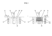
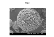
- FIG. 1 is a simplified diagram of an apparatus for powder additive manufacturing according to an embodiment. It is the figure which illustrated the scanning electron microscope (SEM) image of the secondary particle which comprises the powder material concerning one Embodiment.
- SEM scanning electron microscope
- powder material refers to a powdery material used for powder additive manufacturing.
- the powder material is configured by aggregating secondary particles described later, but it goes without saying that mixing of the primary particles described later is allowed.
- the “primary particles” mean the smallest unit that can be identified as a granular material from the appearance, among the morphological components constituting the powder material. In particular, it refers to one particle (one granular material) constituting secondary particles described later.
- the “secondary particles” refer to particles (in the form of particles) in which the primary particles are three-dimensionally combined and behave like a single particle.
- the term “bond” as used herein means that two or more primary particles are directly or indirectly bonded. For example, a bond between primary particles by a chemical reaction or a bond that attracts primary particles by simple adsorption. In addition, a bond using an anchor effect that causes an adhesive or the like to enter the irregularities on the surface of the primary particle, a bond between primary particles using an effect of attracting by static electricity, a bond in which the surface of the primary particle is fused and integrated, and the like are included.
- raw material particles refer to particles constituting a raw material powder for forming a powder material.
- Secondary particles can be produced by three-dimensionally bonding raw material particles by an appropriate method.
- the particles constituting the secondary particles produced in this way are referred to as primary particles.
- the primary particles may have substantially the same form as the raw material particles, or may have different forms from the raw material particles, for example, by integrating two or more raw material particles so that they react or cannot be distinguished formally. May be.
- the primary particles may have the same composition as the raw material particles, or may have a composition different from that of the raw material particles, for example, by reaction of two or more kinds of raw material particles.
- the “flattening step” in powder additive manufacturing means a step of supplying a powder material to an optional layered area of an additive manufacturing apparatus and depositing it uniformly and thinly at a constant thickness.
- powder additive manufacturing is performed in the following steps.
- a step of supplying a powder material to the lamination area of the powder additive manufacturing apparatus (2) A step of forming a thin layer by flattening the supplied powder material with a wiper or the like so as to deposit uniformly and thinly on the lamination area (3) Step of solidifying the powder material by providing means for joining and sintering the powder material to the thin layer of the formed powder material (4) Supplying a new powder material on the solidified powder material (Step (1) above), and thereafter, steps (2) to (4) are repeated to obtain a target three-dimensional structure. That is, the “planarization step” referred to here mainly refers to a step of obtaining a thin layer by depositing the powder material uniformly and thinly on the entire laminated area in the step (2).
- solidification means that the secondary particles constituting the powder material are directly bonded by melting and solidification or indirectly bonded through a binder, so that the shape is a predetermined cross-sectional shape. Including immobilization.
- average particle diameter with respect to a powder material (typically secondary particles) is a volume-based particle size distribution measured by a particle size distribution measuring apparatus based on a laser scattering / diffraction method unless otherwise specified. It means the particle diameter (50% volume average particle diameter; D50) at an integrated value of 50%.
- the “average particle diameter” relating to the primary particles of the powder material is a value calculated as the diameter (spherical equivalent diameter) of the spherical particles.
- the average particle diameter (Dave) of such primary particles can be determined based on the following equation, where Sm is the specific surface area of the entire powder material and ⁇ is the density.
- Sm is the specific surface area of the entire powder material
- ⁇ is the density.
- the value (weighted total value) which added the density of these secondary materials according to the mixture ratio can be employ
- Dave 6 / ( ⁇ Sm)
- the “specific surface area” is determined by measuring the amount of gas (typically nitrogen (N 2 ) gas) physically adsorbed on the surface of the powder material based on the BET method. It means the value obtained by dividing all the external and internal surface areas of the particles constituting the material by their mass. Such a specific surface area can be measured in accordance with JIS Z 8830: 2013 (ISO 9277: 2010) “Method for measuring specific surface area of powder (solid) by gas adsorption”.
- gas typically nitrogen (N 2 ) gas
- the particle size distribution of the powder material means what size (particle diameter) of the particles constituting the powder material, and what proportion (the total powder material is 100%). Relative particle amount at the time).
- the “particle size range” is an index indicating the lower limit and the upper limit (expansion) of the particle diameter of the powder material.
- the lower limit value of the particle size range in this specification means that the proportion of particles having a particle size equal to or smaller than that value in the powder material is 5% or less.
- the upper limit value of the particle size range means that the ratio of particles having a particle diameter equal to or larger than that value in the powder material is 5% or less.
- the particle size distribution of powder material it can measure with the appropriate particle size distribution measuring apparatus according to the particle size of the said powder material.
- the appropriate particle size distribution measuring apparatus can be obtained using a low tap tester (see JIS R6002) or a measuring instrument employing a laser diffraction / scattering method.
- the proportion of particles having a particle size of 5 ⁇ m or less is 5% or less
- the proportion of particles having a particle size of 75 ⁇ m or more is 5% or less. It means that.
- ⁇ Measuring method of average particle diameter of raw material powder when measuring the “average particle diameter” of the raw material particles, the measurement is performed based on the laser scattering / diffraction method in the same manner as the powder material. However, for example, for a particle group having an average particle diameter of less than 1 ⁇ m, the average particle diameter is calculated based on the specific surface area in accordance with the method for measuring the average particle diameter of the primary particles described above.
- the “roundness” of the powder material is the trueness obtained for a planar image (for example, a secondary electron image) of 100 or more secondary particles observed by an observation means such as an electron microscope. Means the arithmetic average of circularity.
- the roundness is a value defined by the following formula from the peripheral length that is the length of the contour of the secondary particle and the area surrounded by the contour in the planar image of the secondary particle. .
- aspects ratio means an arithmetic average value of aspect ratios obtained for planar images (secondary electron images, etc.) of 100 or more secondary particles observed by observation means such as an electron microscope. To do.
- the aspect ratio is defined as a / b, where a is the major axis length and b is the minor axis length in the equivalent ellipse of the secondary particles.
- the equivalent ellipse means an ellipse having the same area as the secondary particles and equal primary and secondary moments.
- Such an average aspect ratio can be obtained, for example, by analyzing an electron microscope image acquired at an appropriate magnification using image processing software or the like.
- the “fractal dimension” means an arithmetic average value of a fractal dimension obtained for a planar view image (secondary electron image, etc.) of 100 or more secondary particles observed by observation means such as an electron microscope. means. Further, in this specification, the fractal dimension employs a value obtained by a divider method, and is a linear function of a function that correlates the logarithm of the peripheral length and stride length of the secondary particle in the planar image of the secondary particle. Defined as the slope of the part.
- Such an average fractal dimension can be obtained, for example, by analyzing an electron microscope image acquired at an appropriate magnification using image processing software or the like.
- the “repose angle” is a base angle calculated from the diameter and height of a conical deposit generated by dropping a powder material from a fixed height funnel onto a horizontal substrate. I mean. Such angle of repose can be measured in accordance with the provisions of JIS R 9301-2-2: 1999 “Alumina powder physical property measurement method-2: angle of repose”.
- the “flow function” is a value called a so-called relative flow index (RFI), and a predetermined amount of a powder material is placed in a container having an inner diameter of 50 mm, and is kept at room temperature and normal humidity.
- the maximum principal stress and the uniaxial collapse stress of the powder material when a shearing force of 9 kPa is applied to the powder material are measured, and the measured value of the maximum principal stress is divided by the measured value of the uniaxial collapse stress. Value.
- the larger this flow function the better the fluidity of the powder material.
- the “compressive strength” relating to the powder material is measured using an electromagnetic force load type compression tester. Specifically, a measurement sample is fixed between a pressure indenter and a pressure plate, and a load force is applied at a constant increase rate by electromagnetic force. Compression is performed by a constant load speed compression method, and the amount of deformation of the measurement sample at that time is measured. The measured deformation characteristic results of the sample are processed by a dedicated program to calculate the strength value.
- the powder material used in the powder additive manufacturing of the present embodiment is composed of particles having a form of secondary particles in which primary particles are three-dimensionally bonded with a gap (hereinafter, “primary particles have a gap”).
- “Particles having the form of secondary particles combined three-dimensionally” are simply referred to as “secondary particles”).
- the term “configured” as used herein means that the constituents of the powder material used for powder additive manufacturing are mainly composed of the secondary particles described above, and “mainly” means 90% of the powder material. It is preferable that the secondary particles occupy% or more, more preferably 95% by mass or more, and still more preferably 98% by mass or more.
- Examples of the powder additive manufacturing method in the present embodiment include a laser powder build-up method (laser metal deposition method; LMD), a selective laser melting method (select laser melting method; SLM), and an electron beam melting method (electron).
- Examples thereof include a beam irradiation method such as a beam melting method (EBM), and an ink jet method in which a binder (binder) is ejected by an ink jet to form a bonding layer of powder particles.
- the laser metal deposition method provides a powder material to a desired part of a structure, and irradiates a laser beam on the material to melt and solidify the powder material. It is a technique to perform. By using this technique, for example, when physical deterioration such as wear occurs in the structure, the material constituting the structure or the reinforcing material as the powder material is supplied to the deteriorated part, and the powder By melting and solidifying the material, it is possible to build up the deteriorated part.
- the selective laser melting method is an operation of scanning a laser beam onto a powder layer on which a powder material is deposited based on slice data created from a design drawing, and melting and solidifying the powder layer into a desired shape.
- This is a technique for modeling a three-dimensional structure by repeatedly laminating each slice data).
- the electron beam melting method is based on slice data created from 3D CAD data, and the above powder layer is selectively melted and solidified using an electron beam to form a three-dimensional structure.
- Any technique includes a step of supplying a powder material, which is a raw material of the structure, to a predetermined modeling position.
- the select laser melting method and the electron beam melting method it is necessary to repeat a flattening process in which a powder material is uniformly and thinly deposited with a thickness corresponding to one cross-sectional thickness over the entire lamination area where a structure is formed.
- the fluidity of the powder material is an important parameter and greatly affects the finish of the three-dimensional structure to be produced.
- the powder material used for the powder additive manufacturing in the present invention has good fluidity, a three-dimensional structure with good finish can be produced.
- the powder material in the present embodiment is mainly composed of particles having a form of secondary particles in which primary particles are three-dimensionally bonded with a gap. If it is a particle
- the raw material particles that have been used in conventional powder additive manufacturing are particles that are monodispersed, if the average particle size is small, the fluidity tends to decrease as the contact area between the particles increases. In the case of the powder material in the present invention, even if the average particle diameter of the primary particles is small, since the primary particles form secondary particles, the fluidity corresponding to the average particle diameter of the secondary particles is good.
- the powder material in the present invention has a gap, so that heat is easily transmitted and the powder material is easily dissolved. As a result, the gap between the secondary particles disappears, and a three-dimensional structure with high density and high hardness close to a sintered body (bulk body) manufactured using a conventional mold can be produced.
- Such a powder material is realized, for example, in the form of granulated particles, granulated sintered particles, fine particle-coated particles in which fine particles are bonded around core particles, and the like. From the viewpoint of realizing a powder material excellent in fluidity particularly suitable for three-dimensional molding, granulated particles or granulated sintered particles are preferable.
- the powder material in the present embodiment is a particle having a form of secondary particles in which primary particles are three-dimensionally joined with a gap, and the manufacturing method thereof is a manufacturing method capable of realizing such a form.
- the granulation sintering method is a technique in which raw material particles are granulated into secondary particles and then sintered to firmly bond (sinter) the raw material particles.
- granulation can be carried out using a granulation method such as dry granulation or wet granulation.
- Specific granulation methods include, for example, rolling granulation method, fluidized bed granulation method, stirring frame granulation method, crushing granulation method, melt granulation method, spray granulation method, microemulsion granulation method Law.
- a spray granulation method is a preferable granulation method.
- a powder material can be produced by the following procedure. That is, first, raw material particles having a desired composition are prepared, and the surface thereof is stabilized with a protective agent or the like as necessary. Then, the stabilized raw material particles are dispersed in an appropriate solvent together with, for example, a binder and spacer particles made of an organic material or the like contained as necessary, to prepare a spray liquid.
- the dispersion of the raw material particles in the solvent can be carried out using, for example, a mixer such as a homogenizer or a blade-type stirrer, a disperser, or the like. And this spray liquid is sprayed using an ultrasonic sprayer etc., and a droplet is formed.
- Such droplets are, for example, placed in an air stream and passed through a continuous furnace. Then, while being transported in the continuous furnace, the droplets are dried in a low temperature zone provided relatively upstream in the furnace to remove the solvent component, and then fired in a high temperature zone provided relatively downstream in the furnace. Is done. At this time, the granulated raw material particles are sintered at the contact points of each other, and sintered while maintaining the granulated shape in general. Thereby, it is possible to obtain a powder material composed of particles in the form of secondary particles in which primary particles are bonded with a gap.
- the primary particles may have substantially the same size and shape as the raw material particles, or the raw material particles may be grown and bonded by firing.
- the raw material particles and the binder are in a uniform mixed state, and the raw material particles are bound by the binder to form mixed particles.
- raw material particles and spacer particles are bound by a binder in a uniform mixed state to constitute mixed particles.
- the binder (and spacer particles) disappear (burn out), and the raw particles are sintered, so that the primary particles are bonded with a gap. Is formed.
- sintering depending on the composition and size of the raw material particles, a part of the raw material particles may become a liquid phase and contribute to bonding with other particles. Therefore, the average particle diameter of the primary particles may be larger than the starting material raw material particles.
- the average particle diameter of the secondary particles obtained is much smaller than the size of the droplets due to the disappearance of components other than the raw material particles and the sintering of the raw material particles due to firing during the period from drying to sintering.
- the average particle diameter of these secondary particles and primary particles and the size and ratio of the gaps formed between the primary particles can be appropriately designed according to the desired form of the secondary particles.
- the concentration of the raw material particles of the spray liquid to be adjusted is preferably 10 to 40% by mass.
- the binder to be added include carboxymethyl cellulose, polyvinyl pyrrolidone, and polyvinyl pyrrolidone.
- the binder to be added is preferably adjusted at a ratio of 0.05 to 10% by mass with respect to the mass of the raw material particles.
- the environment for firing is not particularly limited, but may be in the air, in a vacuum, or in an inert gas atmosphere, and is preferably sintered at a temperature of 600 ° C. or higher and 1600 ° C. or lower.
- the particles when spacer particles made of an organic material or the like, a binder, or the like is used, the particles may be sintered in an atmosphere in which oxygen exists for the purpose of removing the organic material in the granulated particles. If necessary, the produced secondary particles may be crushed and classified.
- the configuration (composition) of the secondary particles is not particularly limited. What is necessary is just to select suitably by the target three-dimensional modeling object to produce, for example, the secondary particle which consists of a plastics, resin, a metal, an alloy, ceramics, cermet, or those mixtures.
- the secondary particle which consists of a plastics, resin, a metal, an alloy, ceramics, cermet, or those mixtures.
- cermet secondary particles are obtained by combining three-dimensionally with a gap between ceramic primary particles and metal primary particles obtained from a mixture of raw material particles made of ceramic particles and raw material particles made of metal particles. Next particle.
- the configuration (composition) of these secondary particles is determined by the selection of raw material particles.
- the composition of the raw material particles is not particularly limited.
- the material is appropriately selected according to the desired powder material (secondary particles) to be manufactured, and is, for example, a material made of plastic, resin, metal, alloy, ceramics, or a mixture thereof.
- the resin examples include a crosslinked resin, a thermoplastic resin, a thermosetting resin, and the like.
- Specific examples of cross-linked resin particles include: “New development of nanoparticles and ultrafine particles (Toray Research Center)”, “Applied technology of ultrafine particle polymers (CMC (supervised by Soichi Muroi))”, “Polymer fine particles Can be synthesized by a known method (emulsion polymerization method, dispersion polymerization method, suspension polymerization method) described in "Technology and Application (CMC (Shinzo Omi, et al., Supervised))”.
- Cross-linked resin particles refer to particles having a cross-linking in the interior of particles made of synthetic resin.
- Crosslinkable chemical bonds can be generated by the use of crosslinkers with two or more reactive groups per molecule.
- the cross-linking agent can take any form of monomer, oligomer or polymer.
- Crosslinked resin particles can be produced by addition polymerization using a polyfunctional monomer in combination or synthesis of polyurethane using a tri- or higher functional polyol and / or a tri- or higher functional polyisocyanate.
- (meth) acrylic acid having a functional group (glycidyl group, hydroxyl group, activated ester group, etc.)
- a crosslinking reaction can be caused by the functional group.
- the cross-linked resin particles are cross-linked resin particles in which the inside of the particles is cross-linked, and the particle surface also has cross-links, but preferably does not have chemical bonds between the particles.
- the crosslinked resin particles that can be used in the present invention include water and general-purpose organic solvents (for example, alcohols (for example, methyl alcohol, ethyl alcohol, propyl alcohol, butyl alcohol, fluorinated alcohol, etc.), ketones (for example, Acetone, methyl ethyl ketone, cyclohexanone, etc.), carboxylic acid esters (eg, methyl acetate, ethyl acetate, propyl acetate, butyl acetate, methyl propionate, ethyl propionate, etc.), ethers (eg, diethyl ether, dipropyl ether, tetrahydrofuran, dioxane) Etc.), and halogenated hydrocarbons (for example, methylene
- the crosslinked resin particles that can be used as raw material particles in the present invention are preferably crosslinked resin particles obtained by polymerizing a composition containing at least one polyfunctional ethylenically unsaturated compound.
- the polyfunctional ethylenically unsaturated compound that is, the polyfunctional monomer is preferably a bifunctional to tetrafunctional monomer, and more preferably a bifunctional or trifunctional monomer.
- Crosslinking with monofunctional monomers alone does not yield cross-linked particles, and cross-linking with bi- to tetra-functional monomers can prevent aggregation between resin particles and keep the particle size distribution of cross-linked resin particles sharp. I can.
- the present invention is preferably a crosslinked resin particle obtained by polymerizing a composition containing two or more polyfunctional ethylenically unsaturated compounds, and the polyfunctional ethylenically unsaturated compound has two or more ethylenically unsaturated compounds. It is also preferable.
- the polyfunctional monomer having two or more types of ethylenically unsaturated bonds a polyfunctional ethylenically unsaturated compound having at least a (meth) acryloyl group and an allyl group is preferable.
- the crosslinked resin particles As a polymerization method used for the production of the crosslinked resin particles, a suspension of hydrophobic polyfunctional monomer / monofunctional monomer is suspended in water for suspension polymerization, or dispersed in a suitable medium for dispersion polymerization.
- the desired crosslinked resin particles can be obtained by emulsion polymerization by emulsifying in water, or by dispersion polymerization in a solution obtained by adding a poor solvent for the produced polymer to the monomer mixture.
- the crosslinked resin particles when used as the raw material particles, the crosslinked resin particles are preferably formed by a dispersion polymerization method or a suspension polymerization method, and more preferably formed by a dispersion polymerization method.
- crosslinked resin particles having a particle size of 1 to 50 ⁇ m can be produced.
- an emulsifier and a dispersion stabilizer can be appropriately used.
- the dispersion stabilizer include polyvinyl alcohol and polyvinyl pyrrolidone (PVP).
- thermoplastic resin refers to a synthetic resin that can be molded by heating, and there is no particular limitation on the type.
- thermoplastic means a property that reversibly softens when heated and can be plastically deformed, and reversibly cures when cooled.
- a resin having a chemical structure composed of a linear or branched polymer can be considered.
- polyvinyl chloride PVC
- PE polyethylene
- PP polypropylene
- PS polystyrene
- thermoplastic polyester acrylonitrile butadiene styrene
- ABS acrylonitrile styrene
- AS polyacrylonitrile styrene
- PMMA methyl methacrylate
- PVA polyvinyl alcohol
- PVDC polyvinylidene chloride
- PET polyethylene terephthalate
- PET vinyl acetate
- PA polyamide
- POM polyacetal
- PC polycarbonate
- PPE polyphenylene ether
- m-PPE modified polyphenylene ether
- PBT ultrahigh molecular weight polyethylene
- UHPE polyvinylidene fluoride
- PVdF polyvinylidene fluoride
- UHPE polyvinylidene fluoride
- PVdF polyvinylidene fluoride
- UHPE polyvinylidene fluoride
- resins such as polyalkylene terephthalate typified by polyvinyl chloride, polycarbonate, PET, and PBT, and polymethylmethacryl are preferable. Any one of these may be used alone, or two or more may be used in combination.
- thermosetting resin is a synthetic resin that undergoes polymerization to form a polymer network structure upon heating and does not return to its original state after curing.
- thermosetting is a property in which a reaction proceeds in a polymer by heating and crosslinking occurs to form a network structure and cure.
- phenol resin PF
- epoxy resin EP
- melamine resin MF
- urea resin urea resin, UF
- unsaturated polyester resin UP
- alkyd resin polyurethane
- PUR polyurethane
- thermosetting polyimide PI
- a resin such as a phenol resin, an epoxy resin, or polyurethane is preferable.
- the thermoplastic resin may be, for example, a state of a mixture of low molecular monomers or a polymer that has been polymerized to some extent. Any one of these may be used alone, or two or more of them may be used in combination (including a blend).
- metal and alloy examples include, for example, aluminum (Al), aluminum alloy, iron (Fe), steel, copper (Cu), copper alloy, nickel (Ni), nickel alloy, gold (Au), silver (Ag) ), Bismuth (Bi), manganese (Mn), zinc (Zn), zinc alloy, titanium (Ti), chromium (Cr), molybdenum (Mo), platinum (Pt), zirconium (Zr), iridium (Ir), etc. Is mentioned. Any one of these may be used alone, or two or more may be used in combination.
- the ceramic may be, for example, a ceramic (oxide ceramic) material made of an oxide or a ceramic material made of a non-oxide such as carbide, boride, nitride, or apatite.
- the oxide ceramics are not particularly limited and may be oxides of various metals. Examples of metal elements constituting such oxide ceramics include metalloid elements such as B, Si, Ge, Sb, and Bi, Mg, Ca, Sr, Ba, Zn, Al, Ga, In, Sn, and Pb.
- oxide-based ceramic for example, alumina, zirconia, yttria, chromia, titania, cobaltite, magnesia, silica, calcia, ceria, ferrite, spinel, zircon, nickel oxide, silver oxide, copper oxide, Zinc oxide, gallium oxide, strontium oxide, scandium oxide, samarium oxide, bismuth oxide, lanthanum oxide, lutetium oxide, hafnium oxide, vanadium oxide, niobium oxide, tungsten oxide, manganese oxide, tantalum oxide, terpium oxide, europium oxide, oxide Neodymium, tin oxide, antimony oxide, antimony-containing tin oxide, indium oxide, tin-containing indium oxide, zirconium oxide aluminate, zirconium oxide silicate, hafnium oxide aluminate, acid Hafnium silicate, titanium silicate, lanthanum oxide silicate, lan
- Non-oxide ceramics include, for example, carbides such as tungsten carbide, chromium carbide, vanadium carbide, niobium carbide, molybdenum carbide, tantalum carbide, titanium carbide, zirconium carbide, hafnium carbide, silicon carbide, boron carbide, and borides.
- carbides such as tungsten carbide, chromium carbide, vanadium carbide, niobium carbide, molybdenum carbide, tantalum carbide, titanium carbide, zirconium carbide, hafnium carbide, silicon carbide, boron carbide, and borides.
- Borides such as molybdenum, chromium boride, hafnium boride, zirconium boride, tantalum boride, titanium boride, nitrides such as titanium nitride, silicon nitride, aluminum nitride, forsterite, steatite, cordierite, mullite And barium titanate, lead titanate, lead zirconate titanate, Mn—Zn ferrite, Ni—Zn ferrite, sialon and other composites, and hydroxyapatite, calcium phosphate and other phosphate compounds. Any one of these may be used alone, or two or more may be used in combination.
- any one of these raw material particles may constitute secondary particles alone, or a combination of two or more species may constitute secondary particles.
- the raw material particles when two or more kinds of raw material particles are contained in the secondary particles, part or all of them may form a composite.
- the raw material particles are ceramic materials
- examples of such composite secondary particles include, for example, yttria stabilized zirconia, partially stabilized zirconia, gadolinium doped ceria, lanthanum doped titanic acid. Examples thereof include lead zirconate, the above sialon, and the above composite oxide.
- the secondary particles are composed in a mixed state without being compounded with two or more kinds of raw material particles, some or all of the raw material particles are complexed by using such powder material.
- a shaped body made of a composite can be produced.
- the average particle diameter itself of the powder material may be a size suitable for supplying the powder material in the step of flattening the powder material of the powder additive manufacturing.
- the upper limit of the average particle diameter (volume average diameter) of the secondary particles is not particularly limited. In the case of a larger one, for example, it can be over 100 ⁇ m, but is typically 100 ⁇ m or less, preferably 75 ⁇ m or less, more preferably 50 ⁇ m or less, and even more preferably 35 ⁇ m.
- the filling rate of the powder material improves, for example, in the lamination area. As a result, the density of the produced three-dimensional structure increases, and the finish is improved.
- the lower limit of the average particle diameter (volume average diameter) of the secondary particles is not particularly limited as long as it does not affect the fluidity of the powder material. In the case of a smaller one, for example, it can be 20 ⁇ m, preferably 10 ⁇ m, for example 5 ⁇ m.
- the powder material disclosed here is not necessarily required to have a small secondary particle size. Therefore, for example, when considering the handling when forming such secondary particles and the fluidity of the powder material, the lower limit of the average particle diameter is preferably 1 ⁇ m or more, more preferably 5 ⁇ m or more. It is exemplified that the thickness is 10 ⁇ m or more.
- the average particle diameter of the secondary particles increases, the fluidity of the powder material improves. As a result, the flattening step of the powder material can be performed satisfactorily, and the finished three-dimensional structure to be produced is improved.
- the powder material disclosed herein is composed of secondary particles that are three-dimensionally bonded to the primary particles having an average particle diameter of less than 10 ⁇ m with a plurality of gaps therebetween. Thereby, while maintaining the form of the primary particles, weighting is realized, and even in the case of secondary particles made of different kinds of raw material particles, the component concentration in the powder material is uniform. This provides an entirely new powder material for powder additive manufacturing that combines the advantages of using secondary particles with a smaller average particle size and the advantages of using secondary particles with a larger average particle size. Can be done.
- the average particle size of the primary particles is not particularly limited.
- the average particle diameter of these particles is as follows: Can be adjusted as follows. That is, the average particle diameter of the core particles is close to the average particle diameter of the powder material or substantially matches the average particle diameter of the powder material. Therefore, the average particle diameter of the core particles can be set relatively large.
- the average particle diameter can be 100 ⁇ m or less, typically 50 ⁇ m or less, preferably 30 ⁇ m or less, more preferably 20 ⁇ m or less, and particularly preferably 10 ⁇ m or less.
- the lower limit of the average particle diameter of the core particles is not particularly limited, but is preferably 1 ⁇ m or more in order to ensure a certain degree of fluidity by the core particles.
- the average particle diameter of the core particles can be adjusted by the average particle diameter of the raw material particles.
- the particle size is important in that it functions like a sliding material with respect to the core particle and can remarkably improve the fluidity.
- the average particle size of the fine particles can be 1000 nm or less, and typically can be 500 nm or less.
- the fine particles are more preferably 100 nm or less, more preferably 50 nm or less, and particularly preferably 30 nm or less.
- the lower limit of the average particle diameter of the fine particles is not limited, but may be, for example, 1 nm or more, 5 nm or more, and preferably 10 nm or more.
- the ratio of the fine particles covering the core particles is about 2000 ppm or less on a mass basis, and is preferably about 100 ppm to 2000 ppm, and more preferably about 500 ppm to 1000 ppm.
- the average particle diameter of the primary particles is preferably less than 10 ⁇ m, for example.
- the average particle diameter of the primary particles is preferably 6 ⁇ m or less, and more preferably 3 ⁇ m or less.
- nanometer-order powder has a small weight of a single particle, so that it is easy to flow even in a slight air flow, and the fluidity is usually inferior.
- the weight is secured in the secondary particles, so that the fluidity is not impaired even if the primary particles are made fine on the nanometer order.
- the average particle diameter of the primary particles is preferably 2 ⁇ m or less, and for example, nanoparticles having a size of 1 ⁇ m or less, 500 nm or less, or 100 nm or less can be obtained.
- the average particle diameter of the primary particles is not particularly limited, and can be, for example, 1 nm or more, for example, 2 nm or more, 5 nm or more.
- a sufficient gap is provided between the primary particles constituting the secondary particles.
- a “gap” means a larger space than a space that is inevitably formed when the primary particles are closely packed, for example.
- Such a “gap” may preferably be a space that is 1.2 times or more the space that is inevitably formed when the primary particles are closely packed. The gap can be confirmed by, for example, a specific surface area / pore distribution measuring device.
- the primary particles can be softened or melted at a temperature lower than the melting point of the secondary particles themselves.
- This can be a completely new finding that has not been anticipated. Therefore, such a powder material can be softened or melted in a state lower than the conventional laser output in powder additive manufacturing, for example, and the cost of the process can be reduced.
- the secondary particles are softened or melted efficiently, a dense three-dimensional structure with a low porosity can be produced. Thereby, for example, a three-dimensional structure having characteristics close to the bulk of the powder material can be produced.
- the specific surface area of a powder material is larger than 0.1 m ⁇ 2 > / g. That is, it is preferable that the powder material is mainly composed of secondary particles having a (very) specific surface area.
- the specific gravity of silica (SiO 2 ) is 2.2 g / ml
- the specific surface area of true spherical silica particles having a radius of rm is 1.36 / r ⁇ 10 ⁇ 6 m 2 / It is represented by g.
- the specific surface area of a true spherical silica particle having a radius of 30 ⁇ m is represented by 0.045 m 2 / g.
- the specific gravity of ⁇ -alumina (Al 2 O 3 ) is 3.98 g / ml
- the specific surface area of true spherical alumina having a radius of rm is expressed as 0.75 / r ⁇ 10 ⁇ 6 m 2 / g. Is done. Therefore, for example, the specific surface area of true spherical alumina particles having a radius of 30 ⁇ m is represented by 0.025 m 2 / g.
- the specific surface area of the powder material disclosed herein is preferably 0.1 m 2 / g or more.
- the powder material disclosed herein has a complicated shape (structure) in which the surface form is complicated in three dimensions. That is, the substantial dimension (for example, the thickness of the uneven portion on the surface) can be significantly reduced without being restricted by the average particle diameter of the powder material itself.
- a ceramic material having a high melting point can efficiently absorb heat of a heat source such as a relatively low temperature laser and can be sufficiently softened and melted.
- a powder material capable of efficiently producing a three-dimensional structure made of ceramics is provided.
- the specific surface area of such secondary particles is not particularly limited, but is desirably larger, and is preferably 0.1 m 2 / g or more.
- the particle size range of the powder material is preferably set as appropriate according to the type and conditions of the apparatus used for powder additive manufacturing.
- the particle size range of the powder material may be appropriately adjusted to 5 to 20 ⁇ m, 45 to 150 ⁇ m, 5 to 75 ⁇ m, 32 to 75 ⁇ m, 15 to 45 ⁇ m, 20 to 63 ⁇ m, or 25 to 75 ⁇ m. it can.
- the powder material disclosed herein preferably has an average roundness of less than 1.5 (for example, 1 or more and less than 1.5).
- the average roundness is adopted as an index that can indirectly represent the average sphericity of the secondary particles constituting the powder material, and when the secondary particles are viewed in plan from an arbitrary direction. Means the average roundness. Therefore, this average roundness does not necessarily mean that the secondary particles are in a two-dimensional shape close to a perfect circle, but essentially in a three-dimensional shape close to a perfect sphere. It is intended to be.
- the external shape of the secondary particles containing ceramics is close to a true sphere as described above.
- the influence of crystal planes, ridges, corners, corners, etc. reflecting the crystallinity of the ceramics constituting the particles. Is reduced, the fluidity of secondary particles containing such ceramics can be significantly increased.
- the primary particles may have a form reflecting the high crystallinity of the ceramic, for example, an outer shape such as a prismatic shape or a massive shape.
- high fluidity can be secured by satisfying the above average roundness.
- the average roundness can be an index that can reflect the average sphericity at a level that cannot be expressed by an index such as an average aspect ratio.
- the average roundness of such ceramic particles whose fluidity is improved is preferably as close to 1 as possible, and may be a value of 1 or more.
- the average roundness is preferably 2.7 or less, more preferably 2.0 or less, and may be 1.5 or less, for example 1.2 or less.
- the average aspect-ratio is less than 1.4. This is because, as described above, in secondary particles having an average roundness closer to 1, the roundness may reflect the surface morphology more than the overall morphology of the secondary particles. In other words, in the case of evaluating secondary particles that are close to a perfect circle, the roundness described above becomes more secondary as the contour in the planar view of the secondary particles becomes more complicated at a micro level. It tends to be larger than the degree of change in the overall shape of the.
- the outer shape of the secondary particles by the aspect ratio in addition to the circularity, the outer shape as a whole is closer to a perfect sphere, that is, a secondary particle that is closer to a perfect circle in plan view. be able to.
- the average aspect ratio is preferably 1.5 or less, and more preferably 1.3 or less. Further, for example, it can be set to 1.15 or less, and is preferably 1 or closer to 1.
- an average fractal dimension is less than 1.5.
- Such secondary particles can be complex with a microscopic level of surface morphology. Therefore, by defining the complicated shape of the particle surface with more various indexes, it is possible to obtain secondary particles whose outer shape is closer to a true sphere.
- the fractal dimension is a widely used index for measuring the complex morphology of individual particle surfaces, and the average fractal dimension is a suitable index for indicating the smoothness of the secondary particle surface disclosed herein. It can be.
- the average fractal dimension is preferably 1.1 or less, more preferably 1.05 or less in consideration of the fluidity of the powder material.
- the angle of repose is less than 39 degrees.
- the angle of repose can be one of the indexes that have been widely adopted to show the fluidity of powders.
- it can be an index that can actually reflect the spontaneous fluidity when the powder material is conveyed in the supply device and the modeling device. Therefore, by defining the angle of repose to be small, a powder material having high fluidity can be realized. As a result, it may be a powder material capable of producing a homogeneous three-dimensional structure with higher productivity.
- the angle of repose is preferably 36 degrees or less, and more preferably 32 degrees or less.
- the angle of repose is exemplified as 20 degrees or more.
- the powder material disclosed herein preferably has a flow function of 5.5 or more.
- the angle of repose is an index that can evaluate the fluidity of the powder material in an unloaded state.
- this flow function evaluates the flow characteristics by measuring the shear stress in a compacted state of the powder material, and can be an index that can more practically express the handleability of the powder material. Therefore, even with such a configuration, for example, it is possible to determine that the powder material having an average particle diameter of less than 30 ⁇ m has high fluidity, and to provide a powder material that can produce a three-dimensional structure with higher productivity. it can.
- the lower limit of the compressive strength of the secondary particles constituting the powder material is not particularly limited as long as it is within the range of the compressive strength of the granulated-sintered ceramic particles used for a general powder material, preferably 1 MPa, more preferably Is 10 MPa, more preferably 100 MPa.
- the compressive strength of the secondary particles increases, the holding power of the form of the secondary particles constituting the powder material increases, and the secondary particles can be prevented from collapsing. As a result, the supply of the material powder to the lamination area is stabilized.
- the upper limit of the compressive strength of the secondary particles is not particularly limited as long as it is within the range of the compressive strength of the secondary particles used in a general powder material, preferably 2000 MPa, more preferably 1500 MPa, and still more preferably. Is 1000 MPa. As the compressive strength of the secondary particles decreases, the modeling efficiency of the powder material improves.
- FIG. 1 shows an example of a simplified diagram of an additive manufacturing apparatus for powder additive manufacturing, and as a rough configuration, a laminate area 10 that is a space where additive manufacturing is performed, and a stock 12 that stores powder materials. And a wiper 11 for assisting the supply of the powder material to the laminated area 10 and a solidifying means (ink jet head, laser oscillator, etc.) 13 for solidifying the powder material.
- the stacking area 10 typically has a modeling space in which the outer periphery is surrounded below the modeling surface, and includes a lifting table 14 that can be moved up and down in the modeling space.
- the elevating table 14 can be lowered by a predetermined thickness ⁇ t1, and a target object is modeled on the elevating table 14.
- the stock 12 is disposed beside the laminated area 10 and includes, for example, a bottom plate (elevating table) that can be moved up and down by a cylinder or the like in a storage space surrounded by an outer periphery. By raising the bottom plate, a predetermined amount of the powder material can be supplied (extruded) to the modeling surface.
- the powder material layer 20 having a predetermined thickness ⁇ t1 can be prepared by supplying the powder material layer 20 to the stacked area 10 with the lifting table 14 lowered by a predetermined thickness ⁇ t1 from the modeling surface. it can.
- the powder material extruded from the stock 12 is supplied onto the lamination area 10 by scanning the wiper 11 on the modeling surface, and the surface of the powder material is flattened to form a homogeneous powder material layer 20. be able to.
- the powder material can be sintered or bonded to a desired cross-sectional shape to form the first powder solidified layer 21.
- the lifting table 14 is lowered by a predetermined thickness ⁇ t1 and the powder material is supplied again, and the second powder material layer 20 is formed by smoothing with the wiper 11. Then, only the solidified region corresponding to the slice data of the second layer of the powder material layer 20 is given a heat source, a solidified composition or the like via the solidifying means 13 to solidify the powder material, and the second layer of powder solidified. Layer 21 is formed. At this time, the powder solidified layer 21 of the second layer and the powder solidified layer 21 of the first layer as the lower layer are integrated to form a laminate up to the second layer.
- the elevating table 14 is lowered by a predetermined thickness ⁇ t1 to form a new powder material layer 20, and a heat source, a solidified composition, etc. are applied through the solidifying means 13 to make the required portion a powder solidified layer 21.
- a target three-dimensional structure can be manufactured.
- a means for solidifying the powder material for example, a method of injecting a composition for solidifying the powder material by inkjet, a method of melting and solidifying the powder material by applying heat by a laser, or a powder material If it has a photo-curing property, ultraviolet irradiation or the like is selected in accordance with the photo-curing property.
- a laser for example, a carbon dioxide laser or a YAG laser can be used publicly.
- a composition containing polyvinyl pyrrolidone, polyvinyl alcohol, polyvinyl butyral, polyacrylic acid, polyacrylic acid derivatives, polyamide, etc. as an adhesive For example, a composition containing a polymerization initiator or the like can be used.
- Ar an Ar laser (488 nm) or the like can be used. That is, it is preferable to select an appropriate means for solidifying the powder material according to the characteristics of the powder material to be used.
- the embodiment may be modified as follows.
- -The powder material and the secondary particles constituting it, and further the primary particles constituting the secondary particles may contain components other than the main components such as inevitable impurities or additives. That is, the purity is not particularly limited. However, for example, in the case of an application for forming a three-dimensional structure with higher functionality, it is preferable to avoid mixing an unintended substance (element), and it is preferable that the purity of the powder material is high. From this viewpoint, it is preferable that the purity of the secondary particles and the primary particles constituting the secondary particles is high. For example, the purity is preferably 95% by mass or more, further 99% by mass or more, more preferably 99.9% by mass or more, for example, 99.99% by mass or more.
- These powder materials are, for example, other elements for the purpose of adjusting the color tone of the three-dimensional structure to be formed, such as transfer metal elements and elements such as Na, K, and Rb if ceramics or cermet) May be introduced, or other elements may be introduced for the purpose of enhancing functionality.
- transfer metal elements and elements such as Na, K, and Rb if ceramics or cermet
- some of the elements constituting the powder material may be included in the form of ions or complexes.
- the powder material is a powder composed of particles having the form of secondary particles in which the primary particles are three-dimensionally joined with a gap, but particles having a form other than the secondary particles are used. You may contain. However, the content of particles other than the secondary particles is preferably as small as possible. The reason for this is that, first, the present invention solves problems such as fluidity by using a powder material composed of secondary particles in which primary particles are three-dimensionally joined with a gap in powder additive manufacturing. This is what we can do. Therefore, the effect of the present invention increases as the ratio of secondary particles exhibiting a specific form to the total amount of the powder material increases.
- the effect of the present invention becomes difficult to obtain when the ratio of secondary particles exhibiting a specific form to the total amount of the powder material decreases.
- the secondary particle which shows the specific form of this invention exhibits a further better effect based on the following ideas. For example, when mixing multiple types of single particles such as metal particles and ceramic particles to make a powder material, the specific gravity is different, so particles made of a material with a large specific gravity go down, and conversely particles with a low specific gravity go up Tend to cause component bias in the powder material.
- the secondary particles exhibiting a specific form as in the present invention are used, for example, when cermet particles in which metal particles and ceramic particles are mixed are used as secondary particles, or a plurality of material particles are mixed to form secondary particles. Even when the secondary particles are formed, since the specific gravity as the secondary particles is uniform, there is little occurrence of component bias in the powder material, and the finished three-dimensional structure to be manufactured is improved. Also from this, it is preferable that the ratio of secondary particles exhibiting a specific form is large with respect to the total amount of the powder material. Therefore, the lower limit of the content of the secondary particles relative to the powder material is preferably 90% by weight, more preferably 95% by weight. Moreover, an upper limit is 98 weight% normally and may be suitably adjusted to such an extent that the effect of this invention is not impaired by mixing components other than secondary particles, such as an additive.
- the powder materials of Samples 1 to 4-2 are obtained by granulating and sintering raw material particles made of tungsten carbide (WC) and raw material particles made of cobalt (Co) each having an average particle diameter shown in Table 1.
- the WC / 12 mass% Co cermet powder material having an average particle diameter shown in Table 1 is constituted.
- the powder materials of Samples 101 to 112 are tungsten carbide (WC) and nickel (Ni), chromium carbide (CrC), nickel chromium alloy (NiCr), tungsten carbide (with average particle sizes shown in Table 1, respectively).
- WC) and stellite are used as raw material particles, and the raw material particles of this combination are granulated and sintered to constitute a cermet powder material having an average particle diameter shown in Table 1.
- the powder materials of Samples 9 to 15-2 are obtained by granulating and sintering raw material particles made of alumina (Al 2 O 3 ) each having an average particle diameter shown in Table 2 to obtain the average particles shown in Table 2.
- a diameter Al 2 O 3 ceramic powder material is constituted.
- the powder materials of Samples 35 to 36-2 and 119 to 132 are made of raw material particles made of nickel chromium alloy (NiCr) or raw material particles made of various metals or alloys having the average particle diameter shown in Table 3, respectively. As a result, a powder material made of various metals or alloys including NiCr alloys having an average particle diameter shown in Table 3 is formed.
- the powder materials of Samples 37 and 37-2 are obtained by granulating and sintering raw material particles made of yttria (Y 2 O 3 ) having an average particle diameter shown in Table 4 to obtain an average particle diameter shown in Table 4.
- Y 2 O 3 ceramic powder material 8% by mass of yttria (Y 2 O 3 ) and alumina (Al 2 O 3 ) with respect to zirconia (ZrO 2 ), each having an average particle diameter shown in Table 4.
- the powder materials of Samples 16 to 17-2 and 114 to 118 are Al 2 O 3 nanoparticle-attached powder materials (fine particle coated powders) having an average particle diameter shown in Table 2.
- this powder material is composed of alumina (Al 2 O 3 ) core particles composed of primary particles (average particle size: 3 ⁇ m, 6 ⁇ m, 24 ⁇ m, 23 ⁇ m, 13 ⁇ m), and primary particles (average particle size: 0). .1 ⁇ m, 0.01 ⁇ m, 0.5 ⁇ m), which is prepared by adhering nanoparticles to the surface of the core particles by electrostatic attraction by appropriately blending with alumina (Al 2 O 3 ) nanoparticles. is there.
- the powder materials of Samples 5 to 8 are composed of WC / 12% by mass Co cermet particles having an average particle diameter shown in Table 1 and manufactured by a sintering-grinding method.
- the powder material of Samples 18 to 32 is composed of Al 2 O 3 ceramic particles having an average particle diameter shown in Table 2 manufactured by a melt-pulverization method.
- the powder materials of Samples 33 and 33-2 are composed of PEG-coated Al 2 O 3 particles having an average particle diameter shown in Table 2 by coating Al 2 O 3 particles with polyethylene glycol (PEG).
- the sample 34 is made of NiCr alloy particles having an average particle diameter shown in Table 3 manufactured by an atomizing method.
- the powder material was prepared by the granulation-sintering method according to the following procedure. That is, first, surface treatment of raw material particles (primary particles such as tungsten carbide, cobalt, alumina, yttria, etc.) having a predetermined average particle diameter is carried out and blended to obtain a target composition, and then a binder (PVA : Polyvinyl alcohol) in a solvent (such as a mixed solution of water and alcohol) and sufficiently dispersed to prepare a slurry. Next, the slurry is granulated into droplets using a spray granulator and a dry sintering furnace, and then dried and sintered to obtain secondary particles. And it was set as the powder material by classifying such a secondary particle as needed.
- raw material particles primary particles such as tungsten carbide, cobalt, alumina, yttria, etc.
- a binder PVA : Polyvinyl alcohol
- solvent such as a mixed solution of water and alcohol
- Secondary particles contained in the powder materials of Samples 1 to 4-2, 101 to 112, 9 to 15-2, 35 to 37-2 and 119 to 135 obtained by this granulation-sintering method are, for example, As shown in FIG. 2, very fine primary particles are bonded to each other to have a three-dimensional structure with a gap, thereby forming substantially spherical secondary particles.
- size of the primary particle in these samples is not limited to the example of FIG. 2, It changes variously according to the average particle diameter of raw material particle
- Preparation of the powder material by the sintering-grinding method and the melt-grinding method was performed according to the following procedure. That is, first, raw material particles are blended so that a powder material having a desired composition (for example, cermet powder of tungsten carbide and cobalt, alumina ceramic powder, yttria ceramic powder, etc.) is obtained, and the raw material particles are heated to be sintered or After melting, it is cooled to prepare a solidified product (ingot). The solidified product was pulverized by mechanical means and classified as necessary to obtain a powder material.
- a powder material having a desired composition for example, cermet powder of tungsten carbide and cobalt, alumina ceramic powder, yttria ceramic powder, etc.
- the particles contained in the powder materials of Samples 5 to 8 and 18 to 32 obtained by the sintering-grinding method and the melt-grinding method are relatively dense and strong, and have corners having edges peculiar to the ground powder. It had a shape of a shape or a lump.
- the powder materials of Samples 16 to 118 are relatively dense and strong, reflecting the form of the Al 2 O 3 particles used as the raw material particles, and at first glance have a square or lump shape. It was.
- the powder material of Sample 33 reflects the form of the Al 2 O 3 particles used as the raw material particles, is relatively dense and strong, and has a square or lump shape with edges. It was. Further, the powder material of the sample 34 had a relatively distorted spherical shape although no edge was seen.
- the average particle size of the powder material is a D50 particle size based on a volume-based particle size distribution, in which each powder material was measured using a laser diffraction / scattering particle size measuring instrument (LA-300, manufactured by Horiba, Ltd.). .
- the measurement result of the average particle diameter of the powder material is shown in the column of “average particle diameter” of the powder material (secondary particle) in each table.
- the average particle diameter of the raw material particles is the same as that of the above powder material.
- a laser diffraction / scattering particle size measuring device LA-300, manufactured by Horiba, Ltd.
- D50 particle size based on measured volume-based particle size distribution.
- the average particle diameter was computed based on the specific surface area similarly to the primary particle diameter of the powder material mentioned later.
- the measurement result of the average particle diameter of the raw material particles is shown in the column of “average particle diameter” of the raw material particles in each table.
- the ratio of the average particle diameter of the raw material particles to the average particle diameter of the powder material is also shown as “D raw material / D powder ”.
- the average particle diameter of the powder material As the average particle diameter of the powder material, a value calculated based on the specific surface area of each powder material was adopted. That is, the “average particle diameter (Dave)” relating to the powder material is a value obtained based on the following equation, where Sm is the specific surface area of the powder material, and ⁇ is the density.
- Sm is the specific surface area of the powder material
- ⁇ is the density.
- values of WC / 12 mass% Co: 14.31 g / ml, Al 2 O 3 : 3.98 g / ml, Y 2 O 3 : 5.03 g / ml are adopted. did.
- values calculated from the product sheet and nominal composition can be used.
- the specific surface area of the powder material was measured based on the BET method using nitrogen gas as an adsorbed gas using a flow-type specific surface area automatic measuring device (manufactured by Shimadzu Corporation, Flowsorb II 2300). Specifically, after putting a powder material as a sample into a sample tube, the sample is cooled, nitrogen gas is introduced into the sample tube, and an adsorption / desorption isotherm by a constant volume method gas adsorption method is created.
- the particle size distribution of the powder material was measured for each powder material using a laser diffraction / scattering particle size analyzer.
- the lower limit value of the particle size range is a particle size value when the total volume of particles having a particle size equal to or less than a certain particle size in the total volume of the powder material is 5%. It is obtained using LA-300) manufactured by HORIBA.
- the upper limit value of the particle size range indicates the particle size value when the total volume of particles having a certain particle size or more in the total volume of the powder material is 5%, and is a laser diffraction / scattering particle size measuring device. (LA-300 manufactured by Horiba, Ltd.).
- the measurement result of the particle size range of the powder material composed of the secondary particles is shown in the column of “particle size range” in each table.
- the average aspect ratio of the powder material was determined by observing each powder material with a scanning electron microscope (Scanning Electron Microscope: SEM, manufactured by Hitachi High-Technologies Corporation, S-3000N) in a plan view (magnification 1000 to 2000 times). ) Using image analysis software (Image-Pro Plus, manufactured by Nippon Rover Co., Ltd.), by calculating the arithmetic average of the aspect ratios measured for 100 or more secondary particles.
- the aspect ratio traces the contour of the secondary particle from the contrast of the SEM image, and the major axis length of the corresponding ellipse (the ellipse having the same area and equal primary and secondary moments) is represented by the major axis a and minor axis. The length is the minor axis b, and the aspect ratio defined by a / b is obtained from these values.
- the measurement results of the average aspect ratio of the powder material are shown in the “Aspect ratio” column of each table.
- the average fractal dimension of the powder material element is determined based on image analysis software for planar images obtained by observing each powder material with a scanning electron microscope (SEM, manufactured by Hitachi High-Technologies Corporation, S-3000N). (Image-Pro Plus, manufactured by Nippon Rover Co., Ltd.) was used to calculate the arithmetic average value of the fractal dimension measured for 100 or more secondary particles. SEM analysis conditions were as follows: magnification: 2000 times, bit depth: 8, scanning speed: 80/100 s. In addition, the SEM image used for the measurement of the fractal dimension realizes a resolution in which the peripheral length of the secondary particles is 30 pixels or more (preferably 1280 pixels or more. In this embodiment, 960 ⁇ 1280 pixels).
- L represents the critical load [N]
- d represents the average particle diameter [mm] of the secondary particles.
- the critical load is the magnitude of the compressive load applied to the secondary particles when the amount of displacement of the indenter increases rapidly when a compressive load increasing at a constant speed is applied to the secondary particles with the indenter.
- the measurement results of the compressive strength of the secondary particles are shown in the “compressive strength” column of each table.
- the angle of repose was measured as an index for evaluating the fluidity of the powder material.
- the angle of repose depends on the A.D. B. D. This is a value obtained by applying to a powder property measuring instrument (ABD-72, manufactured by Tsutsui Science Instruments Co., Ltd.). The measurement results of the angle of repose of the powder material are shown in the column of “angle of repose” in each table.
- composition of the secondary particles is cermet (for example, WC / 12% by mass Co), 33 degrees or less, and for ceramics (for example, Al 2 O 3 or Y 2 O 3 ), 34 degrees or less,
- cermet for example, WC / 12% by mass Co
- ceramics for example, Al 2 O 3 or Y 2 O 3
- an angle of repose of 50 degrees or less is a practically suitable level.
- the powder material is a granulated sintered powder made of Al 2 O 3 ceramics, as in the case of the cermet of Table 1, samples 9 to 17 satisfying the requirements of the present invention are used. It was confirmed that the powder material had a fluidity at a practically suitable level with an angle of repose of 34 degrees or less or a flow function of 5.6 or more.
- the melt pulverized powders of Samples 18 to 32 that do not satisfy the requirements of the present invention each have an angle of repose of 35 or more, and the PEG-coated powder has a flow function of 5.4, but samples 9 to 17 are the same material. It was confirmed that the fluidity was inferior to
- the average particle diameter of the core particles substantially matches the average particle diameter of the powder material. Therefore, it was confirmed that the fluidity was improved in all cases when comparing the fluidity with the melt-pulverized powder having an average particle diameter close to that of the melt-ground powder. That is, the fine particle-coated powder of sample 16 has the same average particle diameter as the PEG-coated powder of sample 33. However, the flow function was as high as 5.6 to 5.7 for the sample 16, whereas it was as low as 5.4 for the sample 33, confirming that the fluidity of the sample 16 was enhanced.
- the fine particle-coated powders of Samples 115 and 116 have substantially the same average particle size as the melt-ground powders of Samples 22-24.
- samples 115 and 116 had repose angles of 35 to 36 degrees, while samples 22 to 24 were as large as 35 to 47, confirming that the fluidity of samples 115 and 116 was improved.
- From the results of Samples 17, 114 to 118 it was found that there is no significant effect on the fluidity even if the amount of fine particles covering the core particles is changed. From this, for example, it was found that about 500 to 2000 ppm is sufficient for the fine particles covering the core particles.
- the powder materials of Samples 35 and 36 consisting of secondary particles satisfying the requirements of the present invention are not single particles that do not satisfy the requirements of the present invention.
- the fluidity was a practically suitable level.
- the powder material of Samples 35 and 36 is mainly composed of secondary particles, and therefore has a larger specific surface area than the powder material of Sample 34. Therefore, it was confirmed that the powder materials of Samples 35 and 36 were melted by heating in a short time as compared with the powder material of Sample 34, and modeling itself was possible in a short time.
- a powder material made of a metal material that satisfies the requirements of the present invention its composition is not limited to NiCr alloy, it is a special alloy excellent in corrosion resistance and heat resistance, etc., and used for overlay welding, Also good for CoNiCrAlY alloys, Ni-Co based alloys such as Hastelloy, Inconel, Trivalloy, Waspaloy, low carbon steel such as maraging steel, tool steel such as AISI 4140, high speed steel such as high speed steel, and stainless steel such as SUS316L. It was confirmed that excellent fluidity was obtained.
- These powdered materials has a specific surface area of 0.05 m 2 / g or more (e.g., 0.1 m 2 / g or more, further 0.3 m 2 / g or more), and the shaped as a three-dimensional modeling material As a result, it was confirmed that the irradiation time of the heat source until melting was short. In other words, it has been confirmed that modeling with less energy becomes possible.
- the powder material of the sample 37 is a powder material made of fine Y 2 O 3 ceramic particles having a raw material particle of 10 nm, but the raw material particles constitute secondary particles. It was confirmed that the fluidity was at a practically suitable level. Also, as shown in Samples 133 to 135, ceramic materials having different compositions can be mixed to constitute a powder material. According to the technology disclosed herein, powder materials having various compositions can be flexibly and easily used. I also found that I could prepare.
- the powder material prepared above was layered by the laser powder overlay method, which is powder layered modeling, to obtain a three-dimensional modeled object.
- the above powder material is used to irradiate an SS400 steel plate (50 mm ⁇ 70 mm ⁇ 10 mm) as a substrate with an LD-excited YAG laser and supply an argon (Ar) shield gas while Laser powder overlaying was performed so that the thickness of the laminate as a three-dimensional structure on the material was about 10 mm.
- a disk laser oscillator Trump Inc., TruDisc-4006 capable of transmitting a fixed laser and a diode laser was used.
- the laser focus was about 2.0 mm
- the laser output was about 500 W
- the processing speed was 1000 mm / min.
- the indication “LMD” in the “Method” column of Tables 5, 6 and 7 means that a three-dimensional structure was produced by the laser powder overlaying method using the sample.
- the powder material prepared above was layered by the selective laser melting method, which is powder layered modeling, to obtain a three-dimensional modeled object.
- a laser sintering type powder additive manufacturing system manufactured by EOS, Germany, EOSINT-M250 was used for additive manufacturing. Specifically, the powder material was supplied to the lamination area, and the powder material was flattened with a wiper attached to the apparatus to form a thin layer (40 ⁇ m). A thin layer made of the powder material was irradiated with a YAG laser to form a three-dimensional structure (single layer).
- the process of supplying and flattening the powder material and the process of irradiating with the laser were repeated to form a laminated body (250 layers, about 100 mm ⁇ 100 mm ⁇ 10 mm) as a three-dimensional structure.
- the laser focus was about 150 [mu] m
- the laser output was about 400 W
- the temperature environment was normal temperature
- the atmosphere around the powder material was Ar gas.
- the indication “SLM” in the column of “Method” in Table 5, Table 6, and Table 7 means that a three-dimensional structure was produced by the selective laser melting method using the sample.
- EBM electron beam melting method
- the powder material prepared above was layered by the electron beam melting method, which is powder layered modeling, to obtain a three-dimensional modeled object.
- a three-dimensional electron beam additive manufacturing apparatus (ARCAM AB, Q10) was used for additive manufacturing. Specifically, the powder material was supplied to the lamination area, and the powder material was flattened with a wiper attached to the apparatus to form a thin layer (150 ⁇ m). A thin layer made of the powder material was irradiated with an electron beam to form a three-dimensional structure (single layer).
- the process of supplying and flattening the powder material and the process of irradiating with the electron beam were repeated to form a laminate (67 layers, about 100 mm ⁇ 100 mm ⁇ 10 mm) as a three-dimensional structure.
- the electron beam focal point is about 0.2 ⁇ mm
- the electron beam output is about 500 when the powder material is WC / 12% by mass Co, about 800 when NiCr is used, and when Al 2 O 3 is used.
- the temperature environment was room temperature, and the atmosphere around the powder material was He gas introduced after high vacuum.
- the indication “EBM” in the “Method” column of Tables 5, 6 and 7 means that a three-dimensional structure was produced by the electron beam melting method using the sample.
- the hardness of the three-dimensional structure was measured.
- the hardness was measured for each three-dimensional structure based on the Vickers hardness test method defined in JIS Z 2244: 2009 and JIS R1610: 2003. Specifically, it is obtained when a diamond indenter with a facing angle of 136 ° is pressed against the surface of a three-dimensional structure with a test force of 1.96 N using a hard and micro hardness tester (manufactured by Shimadzu Corporation, HMV-1).
- the Vickers hardness (Hv0.2) was calculated from the indentation.
- Vickers hardness Hv0.2 was similarly calculated about the surface of the bulk body of the same powder material as the powder material which produced the said three-dimensional structure.
- hardness ratio was computed based on following Formula. The results of the hardness ratio of the three-dimensional structure are shown in the “Hardness” column of Tables 5, 6 and 7. Specifically, when the Vickers hardness is 1 or more, it is “ ⁇ ”, when it is 0.95 or more and less than 1, “ ⁇ ”, when it is 0.90 or more and less than 0.95, “ ⁇ ”; When it was smaller than 90, it was set as “x”.
- Hardness ratio (Vickers hardness of three-dimensional structure) / (Vickers hardness of bulk body)
- the porosity of the three-dimensional structure was measured.
- a value measured by an image analysis method was obtained for the cross section of each three-dimensional structure.
- Image-Pro manufactured by Media Cybernetics
- the measurement results of the porosity of the three-dimensional structure are shown in the “Porosity” column of Tables 5, 6 and 7. “ ⁇ ” when the porosity is 1% or less, “ ⁇ ” when the porosity is greater than 1% and 10% or less, “ ⁇ ” when it is greater than 10% and 20% or less, and “ ⁇ ” when it is greater than 20%. ⁇ ”.
Landscapes
- Engineering & Computer Science (AREA)
- Chemical & Material Sciences (AREA)
- Manufacturing & Machinery (AREA)
- Ceramic Engineering (AREA)
- Materials Engineering (AREA)
- Organic Chemistry (AREA)
- Inorganic Chemistry (AREA)
- Structural Engineering (AREA)
- Nanotechnology (AREA)
- Mechanical Engineering (AREA)
- Metallurgy (AREA)
- Chemical Kinetics & Catalysis (AREA)
- Civil Engineering (AREA)
- Composite Materials (AREA)
- Powder Metallurgy (AREA)
- Producing Shaped Articles From Materials (AREA)
- Manufacture Of Metal Powder And Suspensions Thereof (AREA)
Abstract
Priority Applications (5)
| Application Number | Priority Date | Filing Date | Title |
|---|---|---|---|
| JP2016529580A JP6193493B2 (ja) | 2014-06-20 | 2015-06-22 | 粉末積層造形に用いる粉末材料およびそれを用いた粉末積層造形法 |
| US15/320,034 US20170189960A1 (en) | 2014-06-20 | 2015-06-22 | Powder material for powder additive manufacturing and powder additive manufacturing method using same |
| CN202010079054.7A CN111251604B (zh) | 2014-06-20 | 2015-06-22 | 粉末层叠造形中使用的粉末材料和使用其的粉末层叠造形法 |
| EP15810070.1A EP3159141A4 (fr) | 2014-06-20 | 2015-06-22 | Matériau en poudre destiné à être utilisé en modelage de poudre en strates et procédé de modelage de poudre en strates l'utilisant |
| CN201580033423.6A CN106457668A (zh) | 2014-06-20 | 2015-06-22 | 粉末层叠造形中使用的粉末材料和使用其的粉末层叠造形法 |
Applications Claiming Priority (2)
| Application Number | Priority Date | Filing Date | Title |
|---|---|---|---|
| JP2014-127767 | 2014-06-20 | ||
| JP2014127767 | 2014-06-20 |
Publications (1)
| Publication Number | Publication Date |
|---|---|
| WO2015194678A1 true WO2015194678A1 (fr) | 2015-12-23 |
Family
ID=54935653
Family Applications (1)
| Application Number | Title | Priority Date | Filing Date |
|---|---|---|---|
| PCT/JP2015/067933 WO2015194678A1 (fr) | 2014-06-20 | 2015-06-22 | Matériau en poudre destiné à être utilisé en modelage de poudre en strates et procédé de modelage de poudre en strates l'utilisant |
Country Status (5)
| Country | Link |
|---|---|
| US (1) | US20170189960A1 (fr) |
| EP (1) | EP3159141A4 (fr) |
| JP (3) | JP6193493B2 (fr) |
| CN (2) | CN106457668A (fr) |
| WO (1) | WO2015194678A1 (fr) |
Cited By (43)
| Publication number | Priority date | Publication date | Assignee | Title |
|---|---|---|---|---|
| WO2016140064A1 (fr) * | 2015-03-05 | 2016-09-09 | 東邦チタニウム株式会社 | Poudre de titane, lingot et article fritté constitué de poudre de titane |
| JP2016175202A (ja) * | 2015-03-18 | 2016-10-06 | 株式会社東芝 | 三次元造形方法 |
| WO2016185966A1 (fr) * | 2015-05-15 | 2016-11-24 | コニカミノルタ株式会社 | Matériau en poudre, procédé pour la fabrication d'article moulé tridimensionnel et dispositif de moulage en trois dimensions |
| WO2017110829A1 (fr) * | 2015-12-22 | 2017-06-29 | 株式会社フジミインコーポレーテッド | Matériau de mise en forme destiné à être utilisé dans la fabrication additive mettant en oeuvre des poudres |
| WO2017110827A1 (fr) * | 2015-12-22 | 2017-06-29 | 株式会社フジミインコーポレーテッド | Matériau de façonnage destiné à être utilisé dans la fabrication d'additifs en poudre |
| WO2017110828A1 (fr) * | 2015-12-22 | 2017-06-29 | 株式会社フジミインコーポレーテッド | Matériau de mise en forme destiné à être utilisé dans la fabrication additive mettant en oeuvre des poudres |
| JP6162311B1 (ja) * | 2016-11-21 | 2017-07-12 | 冨士ダイス株式会社 | 積層造形法による粉末冶金焼結体の製造方法 |
| JP2017127997A (ja) * | 2016-01-18 | 2017-07-27 | 国立研究開発法人産業技術総合研究所 | 造形用粉末 |
| WO2017132710A1 (fr) * | 2016-02-04 | 2017-08-10 | Ceratizit Austria Gesellschaft M.B.H. | Procédé de fabrication d'un corps en métal dur tridimensionnel par couches |
| JP2017144560A (ja) * | 2016-02-15 | 2017-08-24 | 株式会社Lixil | 窯業原料、成形体の製造方法、及び成形体 |
| WO2017209136A1 (fr) * | 2016-05-30 | 2017-12-07 | 富士フイルム株式会社 | Procédé de production d'un article moulé en phosphate de calcium, article moulé en phosphate de calcium et matériau pour transplantation |
| JP2017226877A (ja) * | 2016-06-22 | 2017-12-28 | パナソニックIpマネジメント株式会社 | 三次元形状造形物の製造方法 |
| JP2018047630A (ja) * | 2016-09-23 | 2018-03-29 | 株式会社Screenホールディングス | 三次元造形装置および三次元造形方法 |
| WO2018068082A1 (fr) * | 2016-10-11 | 2018-04-19 | Effusiontech Pty Ltd | Procédé de formation d'objets 3d |
| JP2018080359A (ja) * | 2016-11-15 | 2018-05-24 | 株式会社リコー | 立体造形用粉末材料、立体造形材料セット、立体造形物製造装置、及び立体造形物の製造方法 |
| DE102017101050A1 (de) | 2017-01-20 | 2018-07-26 | Fraunhofer-Gesellschaft zur Förderung der angewandten Forschung e.V. | Verfahren zur herstellung von hartmetallkörpern mittels 3d-druck |
| JP2018115372A (ja) * | 2017-01-18 | 2018-07-26 | 三菱重工業株式会社 | 積層造形用の金属粉末、その製造方法、及び検査方法 |
| JP2018130835A (ja) * | 2017-02-13 | 2018-08-23 | 株式会社ノリタケカンパニーリミテド | 積層造形用粉体 |
| JP2018149800A (ja) * | 2017-03-14 | 2018-09-27 | 株式会社リコー | 立体造形用樹脂粉末、及び立体造形物の製造装置 |
| JP2018197000A (ja) * | 2016-07-22 | 2018-12-13 | 株式会社リコー | 立体造形用樹脂粉末、立体造形物の製造装置、及び立体造形物の製造方法 |
| KR20180136466A (ko) * | 2016-04-15 | 2018-12-24 | 산드빅 인터렉츄얼 프로퍼티 에이비 | 서멧 또는 초경 합금의 3 차원 인쇄 |
| CN109715844A (zh) * | 2016-09-16 | 2019-05-03 | 福吉米株式会社 | 喷镀用材料 |
| CN110121392A (zh) * | 2016-12-28 | 2019-08-13 | 三菱电机株式会社 | 冶金用粉末以及使用该冶金用粉末的成型品的制造方法 |
| JP2019137031A (ja) * | 2018-02-07 | 2019-08-22 | 株式会社リコー | 立体造形用粉末、立体造形物の製造装置、立体造形物の製造方法及び樹脂粉末 |
| JP2019181930A (ja) * | 2018-04-03 | 2019-10-24 | キヤノン株式会社 | セラミックス粉体、セラミックス粉体の製造方法およびセラミックス粉体を用いたセラミックス構造物の製造方法 |
| JP2019536890A (ja) * | 2016-11-21 | 2019-12-19 | エルジー・ケム・リミテッド | 3dプリンティング用組成物 |
| JP2020023410A (ja) * | 2018-08-06 | 2020-02-13 | 株式会社フジミインコーポレーテッド | 粉末材料 |
| JP2020505512A (ja) * | 2017-04-28 | 2020-02-20 | ヒューレット−パッカード デベロップメント カンパニー エル.ピー.Hewlett‐Packard Development Company, L.P. | 金属性構築材料粒状物 |
| JP2020040395A (ja) * | 2018-09-07 | 2020-03-19 | 株式会社リコー | 樹脂粉末及びその製造方法、立体造形物の製造方法、並びに立体造形物の製造装置 |
| WO2020100756A1 (fr) | 2018-11-12 | 2020-05-22 | 株式会社フジミインコーポレーテッド | Matériau en poudre pour utilisation dans le moulage de stratifié en poudre, procédé de moulage de stratifié en poudre utilisant celui-ci, et article moulé |
| WO2020100542A1 (fr) | 2018-11-12 | 2020-05-22 | 株式会社フジミインコーポレーテッド | Matériau en poudre destiné à être utilisé dans le moulage de stratifié à partir de poudres, procédé de moulage de stratifié à partir de poudres le mettant en œuvre, et article moulé |
| JP2020537038A (ja) * | 2017-10-09 | 2020-12-17 | ウッデホルムズ アーベー | 熱間加工工具に適した鋼 |
| EP3770205A1 (fr) | 2019-07-26 | 2021-01-27 | Ricoh Company, Ltd. | Poudre de résine pour la fabrication de formes libres solides, dispositif de fabrication d'un objet de fabrication de formes libres solides et procédé de fabrication d'un objet de fabrication de formes libres solides |
| JP2021016349A (ja) * | 2019-07-19 | 2021-02-15 | 株式会社明治 | 三次元成形材料及び三次元食品の製造方法 |
| EP3797906A1 (fr) | 2019-09-30 | 2021-03-31 | Fujimi Incorporated | Matériau en poudre et procédé de fabrication d'un article moulé |
| WO2021090918A1 (fr) * | 2019-11-08 | 2021-05-14 | 大同特殊鋼株式会社 | Matériau en poudre |
| CN113939605A (zh) * | 2019-06-13 | 2022-01-14 | 福田金属箔粉工业株式会社 | 层压成形用铜粉末、层压成形体、层压成形体的制造方法及层压成形装置 |
| JP2022507276A (ja) * | 2019-04-12 | 2022-01-18 | チューハイ セイルナー スリーディー テクノロジー カンパニー リミテッド | 三次元物体成形方法及び成形装置 |
| JP2022120580A (ja) * | 2021-02-05 | 2022-08-18 | 株式会社ExOne | 積層造形用粉末材料 |
| WO2022210134A1 (fr) | 2021-03-31 | 2022-10-06 | 株式会社フジミインコーポレーテッド | Matériau en poudre pour formage en couche par couche et procédé de fabrication d'un produit formé à l'aide d'un matériau en poudre |
| US11786967B2 (en) | 2016-05-11 | 2023-10-17 | Proterial, Ltd. | Composite member manufacturing method and composite member |
| WO2024024109A1 (fr) * | 2022-07-29 | 2024-02-01 | 技術研究組合次世代3D積層造形技術総合開発機構 | Dispositif de fabrication additive et procédé de fabrication additive |
| JP7468858B2 (ja) | 2020-01-28 | 2024-04-16 | 株式会社ナノシーズ | 粉末層の形成方法および形成装置 |
Families Citing this family (58)
| Publication number | Priority date | Publication date | Assignee | Title |
|---|---|---|---|---|
| CN104837556B (zh) | 2012-10-05 | 2018-04-03 | 康奈尔大学 | 包埋在大孔支架中的酶形成的介孔集合 |
| EP3142179B1 (fr) * | 2014-07-30 | 2019-02-27 | LG Chem, Ltd. | Procédé de fabrication d'une membrane d'électrolyte inorganique ayant une compacité améliorée, composition pour la fabrication de membrane d'électrolyte inorganique, et membrane d'électrolyte inorganique fabriquée utilisant ceux-ci |
| CA2986197C (fr) | 2015-05-18 | 2023-10-17 | Zymtronix, Llc | Enzymes microbicides immobilises magnetiquement |
| CA2992261A1 (fr) | 2015-07-15 | 2017-01-19 | Zymtronix, Llc | Production automatisee de bionanocatalysateurs |
| US20170246679A1 (en) * | 2016-02-29 | 2017-08-31 | General Electric Company | Casting with graded core components |
| CN109788762B (zh) | 2016-08-13 | 2023-07-11 | 齐姆特罗尼克斯催化系统股份有限公司 | 磁性固定化的杀生物酶和杀生物化学品 |
| CN106825567B (zh) * | 2017-01-22 | 2018-12-11 | 清华大学 | 电子束选区熔化与电子束切割复合的增材制造方法 |
| JP6862917B2 (ja) * | 2017-02-28 | 2021-04-21 | セイコーエプソン株式会社 | 三次元造形物製造用組成物および三次元造形物の製造方法 |
| KR20180103668A (ko) * | 2017-03-09 | 2018-09-19 | (주)엘지하우시스 | 열가소성 고분자 입자의 제조방법 |
| CN107141004B (zh) * | 2017-06-13 | 2020-02-14 | 华中科技大学 | 一种碳化硼复合材料及其制备方法 |
| JP2019018477A (ja) * | 2017-07-19 | 2019-02-07 | 株式会社ミマキエンジニアリング | 三次元造形物の製造方法及び三次元造形物製造用インク |
| GB2565063B (en) | 2017-07-28 | 2020-05-27 | Oxmet Tech Limited | A nickel-based alloy |
| US10926480B2 (en) * | 2017-09-05 | 2021-02-23 | The Boeing Company | Methods for manufacturing components having spatially graded properties |
| CN107825706A (zh) * | 2017-12-15 | 2018-03-23 | 佛山三维二次方科技有限公司 | 热塑性高分子材料的3d打印工艺 |
| EP3524430B1 (fr) * | 2018-02-07 | 2021-12-15 | Ricoh Company, Ltd. | Poudre pour la fabrication de formes libres solides, et procédé de fabrication de formes libres solides |
| JP6910977B2 (ja) * | 2018-03-07 | 2021-07-28 | 株式会社日立製作所 | 粉末積層造形装置 |
| WO2019177614A1 (fr) | 2018-03-15 | 2019-09-19 | Hewlett-Packard Development Company, L.P. | Composition |
| CN111788256A (zh) * | 2018-04-02 | 2020-10-16 | 松下知识产权经营株式会社 | 树脂粉末、密封材料、电子部件以及树脂粉末制造方法 |
| CN108478860A (zh) * | 2018-04-04 | 2018-09-04 | 昆明理工大学 | 一种钙磷盐-二氧化硅多孔支架及其制备方法 |
| WO2019246321A1 (fr) * | 2018-06-20 | 2019-12-26 | Desktop Metal, Inc. | Procédés et compositions pour la préparation de poudres pour la fabrication additive métallique en trois dimensions à base de liant |
| CN109173925B (zh) * | 2018-07-28 | 2020-08-18 | 西安交通大学 | 分级离散高效蒸发的多级结构粉末材料及其制备方法 |
| JP6526889B1 (ja) * | 2018-08-01 | 2019-06-05 | Jx金属株式会社 | セラミックス層と銅粉ペースト焼結体の積層体 |
| JP6839423B2 (ja) * | 2018-08-06 | 2021-03-10 | 株式会社写真化学 | 光造形用スラリー及びそれを用いた光造形物の製造方法 |
| US11458676B2 (en) * | 2018-09-07 | 2022-10-04 | Ricoh Company, Ltd. | Resin powder and method of manufacturing solid freeform fabrication object |
| EP3620283B1 (fr) * | 2018-09-07 | 2022-03-30 | Ricoh Company, Ltd. | Poudre de résine, et procédé et dispositif de fabrication d'un objet de forme libre solide en utilisant ladite poudre |
| JP2022500067A (ja) | 2018-09-27 | 2022-01-04 | ザイムトロニクス キャタリティック システムズ インコーポレイテッドZymtronix Catalytic Systems, Inc. | 生体ナノ触媒固定化用のプリント可能な磁性粉末及び3dプリント対象物 |
| DE102018217129A1 (de) * | 2018-10-08 | 2020-04-09 | Robert Bosch Gmbh | Gesintertes Metallteil und Verfahren zu seiner Herstellung |
| JP7119890B2 (ja) | 2018-10-22 | 2022-08-17 | セイコーエプソン株式会社 | 三次元造形物の製造装置及び三次元造形物の製造方法 |
| WO2020102025A1 (fr) * | 2018-11-12 | 2020-05-22 | Desktop Metal, Inc. | Techniques de commande de caractéristiques d'écoulement de matériau de construction dans la fabrication additive, ainsi que systèmes et procédés associés |
| AT16308U3 (de) * | 2018-11-19 | 2019-12-15 | Plansee Se | Additiv gefertigtes Refraktärmetallbauteil, additives Fertigungsverfahren und Pulver |
| FR3089145B1 (fr) * | 2018-11-30 | 2021-06-04 | Univ Claude Bernard Lyon | Procédé de fabrication additive assisté par un milieu contraint granulaire |
| US10828836B2 (en) | 2018-12-13 | 2020-11-10 | General Electric Company | Method for melt pool monitoring |
| US10894364B2 (en) | 2018-12-13 | 2021-01-19 | General Electric Company | Method for melt pool monitoring using geometric length |
| US11020907B2 (en) | 2018-12-13 | 2021-06-01 | General Electric Company | Method for melt pool monitoring using fractal dimensions |
| US11285671B2 (en) | 2018-12-13 | 2022-03-29 | General Electric Company | Method for melt pool monitoring using Green's theorem |
| US10828837B2 (en) | 2018-12-13 | 2020-11-10 | General Electric Company | Method for melt pool monitoring using algebraic connectivity |
| CN109485420B (zh) * | 2019-01-15 | 2020-09-15 | 景德镇陶瓷大学 | 一种提高陶瓷纳米粉体的湿法成型性及烧结性的方法 |
| JP7185829B2 (ja) * | 2019-02-20 | 2022-12-08 | セイコーエプソン株式会社 | 三次元造形物の製造方法 |
| EP3936255A4 (fr) * | 2019-03-04 | 2022-12-07 | Hitachi Metals, Ltd. | Poudre d'alliage résistant à la corrosion à base de ni destinée à être utilisée en fabrication additive et procédé de production de produit de fabrication additive utilisant ladite poudre |
| US20200346365A1 (en) * | 2019-05-03 | 2020-11-05 | Kennametal Inc. | Cemented carbide powders for additive manufacturing |
| CN110164677B (zh) * | 2019-06-11 | 2020-11-06 | 莱芜职业技术学院 | 一种制备用于3d打印的铁基软磁复合材料丝材 |
| CN110204943B (zh) * | 2019-06-19 | 2021-04-06 | 武汉钢铁有限公司 | 一种多层结构球粒和制备方法及含多层结构球粒的轻质传热涂料 |
| EP3760412B1 (fr) * | 2019-07-05 | 2022-04-13 | Friedrich-Alexander-Universität Erlangen-Nürnberg | Poudre et procédé pour la préparation d'objets tridimensionnels |
| US11661521B2 (en) * | 2019-12-17 | 2023-05-30 | Ticona Llc | Three-dimensional printing system employing a thermotropic liquid crystalline polymer |
| JP2021146679A (ja) * | 2020-03-23 | 2021-09-27 | 株式会社リコー | 樹脂粉末、立体造形用樹脂粉末、立体造形物の製造方法、及び立体造形物の製造装置 |
| CN111633208B (zh) * | 2020-05-07 | 2022-09-06 | 上海理工大学 | 一种控制粉末流动性对打印成形质量控制方法 |
| CN111718572A (zh) * | 2020-06-18 | 2020-09-29 | 工科思维技术(深圳)有限公司 | 一种适用于3d打印的二维纳米高分子复合丝材的制备方法 |
| US20230278283A1 (en) * | 2020-06-25 | 2023-09-07 | Hewlett-Packard Development Company, L.P. | Shear thinning build material slurry |
| JP2022026529A (ja) * | 2020-07-31 | 2022-02-10 | 株式会社リコー | 立体造形物の製造方法、立体造形物の製造装置、および立体造形物 |
| KR102345950B1 (ko) * | 2020-09-10 | 2022-01-03 | 울산과학기술원 | 고분자 탄성 구조체 및 이의 제조방법 |
| FR3116530B1 (fr) * | 2020-11-26 | 2023-03-31 | Safran Ceram | Procédé de fabrication d’une pièce en matériau composite à matrice céramique |
| CN112813374A (zh) * | 2020-12-29 | 2021-05-18 | 昆山世铭金属塑料制品有限公司 | 一种用于汽车标牌喷涂粉末及其制备方法 |
| CN113600822A (zh) * | 2021-07-23 | 2021-11-05 | 浙江亚通焊材有限公司 | 一种蓄冷材料球形颗粒制备设备和制备方法 |
| WO2023023577A1 (fr) * | 2021-08-20 | 2023-02-23 | The Regents Of The University Of California | Fabrication additive d'architectures 3d polymères modifiables pour des applications multifonctionnelles |
| WO2023081353A1 (fr) * | 2021-11-05 | 2023-05-11 | Oerlikon Metco (Us) Inc. | Alliage de co-ni-cr-w-la résistant aux fissures pour la fabrication additive à base de poudre |
| CN114379079B (zh) * | 2022-01-14 | 2023-11-24 | 杭州捷诺飞生物科技股份有限公司 | 3d打印的控制方法、装置以及电子设备 |
| CN115519118B (zh) * | 2022-09-29 | 2024-01-19 | 晶高优材(北京)科技有限公司 | 提升增材制造金属粉末的流动性、松装及振实密度的方法 |
| CN116550975B (zh) * | 2023-07-04 | 2023-09-26 | 赣州金顺科技有限公司 | 一种金刚石/铜复合材料制备方法 |
Citations (5)
| Publication number | Priority date | Publication date | Assignee | Title |
|---|---|---|---|---|
| JP2006257463A (ja) * | 2005-03-15 | 2006-09-28 | Sony Corp | レーザ焼結処理用の粉状材料及びその製造方法、並びに、3次元構造物及びその製造方法 |
| JP2006321711A (ja) * | 2005-04-20 | 2006-11-30 | Trial Corp | 粉末焼結積層造形法に使用される微小球体、その製造方法、粉末焼結積層造形物及びその製造方法 |
| WO2009020130A1 (fr) * | 2007-08-08 | 2009-02-12 | Techno Polymer Co., Ltd. | Poudre frittable au laser et produit façonné de celle-ci |
| WO2010064696A1 (fr) * | 2008-12-05 | 2010-06-10 | ダイセル・エボニック株式会社 | Particules composites sphériques et procédé de fabrication associé |
| JP2015096646A (ja) * | 2013-10-11 | 2015-05-21 | セイコーエプソン株式会社 | レーザー焼結用粉末、構造物の製造方法および構造物の製造装置 |
Family Cites Families (19)
| Publication number | Priority date | Publication date | Assignee | Title |
|---|---|---|---|---|
| US5182119A (en) * | 1991-04-18 | 1993-01-26 | Ici Americas, Inc. | Apparatus for production of free flowing polytetrafluoroethylene (PTFE) molding pellets |
| US7655586B1 (en) * | 2003-05-29 | 2010-02-02 | Pentron Ceramics, Inc. | Dental restorations using nanocrystalline materials and methods of manufacture |
| JP3784404B1 (ja) * | 2004-11-24 | 2006-06-14 | 株式会社神戸製鋼所 | 溶射ノズル装置およびそれを用いた溶射装置 |
| JP4560387B2 (ja) * | 2004-11-30 | 2010-10-13 | 株式会社フジミインコーポレーテッド | 溶射用粉末、溶射方法及び溶射皮膜 |
| JP5272871B2 (ja) * | 2008-04-21 | 2013-08-28 | パナソニック株式会社 | 積層造形装置 |
| JP2011017058A (ja) * | 2009-07-09 | 2011-01-27 | Sumitomo Metal Mining Co Ltd | 硼化物系サーメット溶射用粉末 |
| JP2011021218A (ja) * | 2009-07-14 | 2011-02-03 | Kinki Univ | 積層造形用粉末材料及び粉末積層造形法 |
| EP2292357B1 (fr) * | 2009-08-10 | 2016-04-06 | BEGO Bremer Goldschlägerei Wilh.-Herbst GmbH & Co KG | Article céramique et procédés de production de cet article |
| JP5399954B2 (ja) * | 2009-09-07 | 2014-01-29 | 株式会社フジミインコーポレーテッド | 溶射用粉末 |
| JP2011143571A (ja) * | 2010-01-13 | 2011-07-28 | Seiko Epson Corp | 造形方法及び造形物 |
| JP5593736B2 (ja) * | 2010-03-02 | 2014-09-24 | セイコーエプソン株式会社 | 造形方法及び造形装置 |
| JP5544945B2 (ja) * | 2010-03-11 | 2014-07-09 | セイコーエプソン株式会社 | 造粒粉末および造粒粉末の製造方法 |
| JP5890843B2 (ja) * | 2011-10-20 | 2016-03-22 | 株式会社東芝 | 溶射用Mo粉末およびそれを用いたMo溶射膜並びにMo溶射膜部品 |
| CN103094550B (zh) * | 2011-10-31 | 2015-02-18 | 北京有色金属研究总院 | 一种富锂正极材料的制备方法 |
| FR2998496B1 (fr) * | 2012-11-27 | 2021-01-29 | Association Pour La Rech Et Le Developpement De Methodes Et Processus Industriels Armines | Procede de fabrication additive d'une piece par fusion selective ou frittage selectif de lits de poudre a compacite optimisee par faisceau de haute energie |
| US9393674B2 (en) * | 2013-04-04 | 2016-07-19 | Smith International, Inc. | Cemented carbide composite for a downhole tool |
| FR3008014B1 (fr) * | 2013-07-04 | 2023-06-09 | Association Pour La Rech Et Le Developpement De Methodes Et Processus Industriels Armines | Procede de fabrication additve de pieces par fusion ou frittage de particules de poudre(s) au moyen d un faisceau de haute energie avec des poudres adaptees au couple procede/materiau vise |
| CN103785860B (zh) * | 2014-01-22 | 2016-06-15 | 宁波广博纳米新材料股份有限公司 | 3d打印机用的金属粉末及其制备方法 |
| US10144061B2 (en) * | 2014-12-30 | 2018-12-04 | Delavan Inc. | Particulates for additive manufacturing techniques |
-
2015
- 2015-06-22 CN CN201580033423.6A patent/CN106457668A/zh active Pending
- 2015-06-22 CN CN202010079054.7A patent/CN111251604B/zh active Active
- 2015-06-22 US US15/320,034 patent/US20170189960A1/en not_active Abandoned
- 2015-06-22 EP EP15810070.1A patent/EP3159141A4/fr active Pending
- 2015-06-22 WO PCT/JP2015/067933 patent/WO2015194678A1/fr active Application Filing
- 2015-06-22 JP JP2016529580A patent/JP6193493B2/ja active Active
-
2017
- 2017-07-03 JP JP2017130450A patent/JP6562977B2/ja active Active
-
2018
- 2018-04-25 JP JP2018084574A patent/JP6633677B2/ja active Active
Patent Citations (5)
| Publication number | Priority date | Publication date | Assignee | Title |
|---|---|---|---|---|
| JP2006257463A (ja) * | 2005-03-15 | 2006-09-28 | Sony Corp | レーザ焼結処理用の粉状材料及びその製造方法、並びに、3次元構造物及びその製造方法 |
| JP2006321711A (ja) * | 2005-04-20 | 2006-11-30 | Trial Corp | 粉末焼結積層造形法に使用される微小球体、その製造方法、粉末焼結積層造形物及びその製造方法 |
| WO2009020130A1 (fr) * | 2007-08-08 | 2009-02-12 | Techno Polymer Co., Ltd. | Poudre frittable au laser et produit façonné de celle-ci |
| WO2010064696A1 (fr) * | 2008-12-05 | 2010-06-10 | ダイセル・エボニック株式会社 | Particules composites sphériques et procédé de fabrication associé |
| JP2015096646A (ja) * | 2013-10-11 | 2015-05-21 | セイコーエプソン株式会社 | レーザー焼結用粉末、構造物の製造方法および構造物の製造装置 |
Non-Patent Citations (1)
| Title |
|---|
| See also references of EP3159141A4 * |
Cited By (68)
| Publication number | Priority date | Publication date | Assignee | Title |
|---|---|---|---|---|
| WO2016140064A1 (fr) * | 2015-03-05 | 2016-09-09 | 東邦チタニウム株式会社 | Poudre de titane, lingot et article fritté constitué de poudre de titane |
| US10442000B2 (en) | 2015-03-05 | 2019-10-15 | Toho Titanium Co., Ltd. | Titanium-based powder, and ingot and sintered article thereof |
| JP2016175202A (ja) * | 2015-03-18 | 2016-10-06 | 株式会社東芝 | 三次元造形方法 |
| WO2016185966A1 (fr) * | 2015-05-15 | 2016-11-24 | コニカミノルタ株式会社 | Matériau en poudre, procédé pour la fabrication d'article moulé tridimensionnel et dispositif de moulage en trois dimensions |
| WO2017110829A1 (fr) * | 2015-12-22 | 2017-06-29 | 株式会社フジミインコーポレーテッド | Matériau de mise en forme destiné à être utilisé dans la fabrication additive mettant en oeuvre des poudres |
| WO2017110828A1 (fr) * | 2015-12-22 | 2017-06-29 | 株式会社フジミインコーポレーテッド | Matériau de mise en forme destiné à être utilisé dans la fabrication additive mettant en oeuvre des poudres |
| WO2017110827A1 (fr) * | 2015-12-22 | 2017-06-29 | 株式会社フジミインコーポレーテッド | Matériau de façonnage destiné à être utilisé dans la fabrication d'additifs en poudre |
| US10710157B2 (en) | 2015-12-22 | 2020-07-14 | Fujimi Incorporated | Additive manufacturing material for powder rapid prototyping manufacturing |
| JP2017127997A (ja) * | 2016-01-18 | 2017-07-27 | 国立研究開発法人産業技術総合研究所 | 造形用粉末 |
| WO2017132710A1 (fr) * | 2016-02-04 | 2017-08-10 | Ceratizit Austria Gesellschaft M.B.H. | Procédé de fabrication d'un corps en métal dur tridimensionnel par couches |
| JP2017144560A (ja) * | 2016-02-15 | 2017-08-24 | 株式会社Lixil | 窯業原料、成形体の製造方法、及び成形体 |
| KR20180136466A (ko) * | 2016-04-15 | 2018-12-24 | 산드빅 인터렉츄얼 프로퍼티 에이비 | 서멧 또는 초경 합금의 3 차원 인쇄 |
| JP2019513901A (ja) * | 2016-04-15 | 2019-05-30 | サンドビック インテレクチュアル プロパティー アクティエボラーグ | サーメット又は超硬合金の三次元印刷 |
| KR102514163B1 (ko) | 2016-04-15 | 2023-03-24 | 산드빅 인터렉츄얼 프로퍼티 에이비 | 서멧 또는 초경 합금의 3 차원 인쇄 |
| US11786967B2 (en) | 2016-05-11 | 2023-10-17 | Proterial, Ltd. | Composite member manufacturing method and composite member |
| US10953131B2 (en) | 2016-05-30 | 2021-03-23 | Fujifilm Corporation | Method for producing calcium phosphate molded article, calcium phosphate molded article, and material for transplantation |
| JPWO2017209136A1 (ja) * | 2016-05-30 | 2019-05-16 | 富士フイルム株式会社 | リン酸カルシウム成形体の製造方法、リン酸カルシウム成形体及び移植用材料 |
| WO2017209136A1 (fr) * | 2016-05-30 | 2017-12-07 | 富士フイルム株式会社 | Procédé de production d'un article moulé en phosphate de calcium, article moulé en phosphate de calcium et matériau pour transplantation |
| JP2017226877A (ja) * | 2016-06-22 | 2017-12-28 | パナソニックIpマネジメント株式会社 | 三次元形状造形物の製造方法 |
| JP2018197000A (ja) * | 2016-07-22 | 2018-12-13 | 株式会社リコー | 立体造形用樹脂粉末、立体造形物の製造装置、及び立体造形物の製造方法 |
| CN109715844A (zh) * | 2016-09-16 | 2019-05-03 | 福吉米株式会社 | 喷镀用材料 |
| CN115261762A (zh) * | 2016-09-16 | 2022-11-01 | 福吉米株式会社 | 喷镀用材料 |
| US11359270B2 (en) | 2016-09-16 | 2022-06-14 | Fujimi Incorporated | Thermal spraying matertal |
| CN115261762B (zh) * | 2016-09-16 | 2024-03-19 | 福吉米株式会社 | 喷镀用材料 |
| JPWO2018052128A1 (ja) * | 2016-09-16 | 2019-08-08 | 株式会社フジミインコーポレーテッド | 溶射用材料 |
| JP2018047630A (ja) * | 2016-09-23 | 2018-03-29 | 株式会社Screenホールディングス | 三次元造形装置および三次元造形方法 |
| CN109843591A (zh) * | 2016-10-11 | 2019-06-04 | 易福仁科技私人有限公司 | 形成3d物体的方法 |
| WO2018068082A1 (fr) * | 2016-10-11 | 2018-04-19 | Effusiontech Pty Ltd | Procédé de formation d'objets 3d |
| CN109843591B (zh) * | 2016-10-11 | 2022-02-08 | 易福仁科技知产私人有限公司 | 形成3d物体的方法 |
| JP2018080359A (ja) * | 2016-11-15 | 2018-05-24 | 株式会社リコー | 立体造形用粉末材料、立体造形材料セット、立体造形物製造装置、及び立体造形物の製造方法 |
| JP2018083959A (ja) * | 2016-11-21 | 2018-05-31 | 冨士ダイス株式会社 | 積層造形法による粉末冶金焼結体の製造方法 |
| JP2019536890A (ja) * | 2016-11-21 | 2019-12-19 | エルジー・ケム・リミテッド | 3dプリンティング用組成物 |
| US11232891B2 (en) | 2016-11-21 | 2022-01-25 | Lg Chem, Ltd. | Composition for 3 dimensional printing |
| JP6162311B1 (ja) * | 2016-11-21 | 2017-07-12 | 冨士ダイス株式会社 | 積層造形法による粉末冶金焼結体の製造方法 |
| US10702919B2 (en) | 2016-12-28 | 2020-07-07 | Mitsubishi Electric Corporation | Method for manufacturing alloy molded product |
| CN110121392A (zh) * | 2016-12-28 | 2019-08-13 | 三菱电机株式会社 | 冶金用粉末以及使用该冶金用粉末的成型品的制造方法 |
| JP2018115372A (ja) * | 2017-01-18 | 2018-07-26 | 三菱重工業株式会社 | 積層造形用の金属粉末、その製造方法、及び検査方法 |
| DE102017101050A1 (de) | 2017-01-20 | 2018-07-26 | Fraunhofer-Gesellschaft zur Förderung der angewandten Forschung e.V. | Verfahren zur herstellung von hartmetallkörpern mittels 3d-druck |
| JP2018130835A (ja) * | 2017-02-13 | 2018-08-23 | 株式会社ノリタケカンパニーリミテド | 積層造形用粉体 |
| JP2018149800A (ja) * | 2017-03-14 | 2018-09-27 | 株式会社リコー | 立体造形用樹脂粉末、及び立体造形物の製造装置 |
| JP7043865B2 (ja) | 2017-03-14 | 2022-03-30 | 株式会社リコー | 立体造形用樹脂粉末、及び立体造形物の製造装置 |
| JP2022075764A (ja) * | 2017-03-14 | 2022-05-18 | 株式会社リコー | 立体造形用樹脂粉末、及び立体造形物の製造方法 |
| JP7351363B2 (ja) | 2017-03-14 | 2023-09-27 | 株式会社リコー | 立体造形用樹脂粉末、及び立体造形物の製造方法 |
| JP2020505512A (ja) * | 2017-04-28 | 2020-02-20 | ヒューレット−パッカード デベロップメント カンパニー エル.ピー.Hewlett‐Packard Development Company, L.P. | 金属性構築材料粒状物 |
| JP7159172B2 (ja) | 2017-04-28 | 2022-10-24 | ヒューレット-パッカード デベロップメント カンパニー エル.ピー. | 金属性構築材料粒状物 |
| US11673330B2 (en) | 2017-04-28 | 2023-06-13 | Hewlett-Packard Development Company, L.P. | Metallic build material granules |
| JP2020537038A (ja) * | 2017-10-09 | 2020-12-17 | ウッデホルムズ アーベー | 熱間加工工具に適した鋼 |
| JP7073944B2 (ja) | 2018-02-07 | 2022-05-24 | 株式会社リコー | 立体造形用粉末、立体造形物の製造装置、立体造形物の製造方法及び樹脂粉末 |
| JP2019137031A (ja) * | 2018-02-07 | 2019-08-22 | 株式会社リコー | 立体造形用粉末、立体造形物の製造装置、立体造形物の製造方法及び樹脂粉末 |
| JP2019181930A (ja) * | 2018-04-03 | 2019-10-24 | キヤノン株式会社 | セラミックス粉体、セラミックス粉体の製造方法およびセラミックス粉体を用いたセラミックス構造物の製造方法 |
| JP7083289B2 (ja) | 2018-08-06 | 2022-06-10 | 株式会社フジミインコーポレーテッド | 粉末材料 |
| JP2020023410A (ja) * | 2018-08-06 | 2020-02-13 | 株式会社フジミインコーポレーテッド | 粉末材料 |
| JP2020040395A (ja) * | 2018-09-07 | 2020-03-19 | 株式会社リコー | 樹脂粉末及びその製造方法、立体造形物の製造方法、並びに立体造形物の製造装置 |
| WO2020100756A1 (fr) | 2018-11-12 | 2020-05-22 | 株式会社フジミインコーポレーテッド | Matériau en poudre pour utilisation dans le moulage de stratifié en poudre, procédé de moulage de stratifié en poudre utilisant celui-ci, et article moulé |
| WO2020100542A1 (fr) | 2018-11-12 | 2020-05-22 | 株式会社フジミインコーポレーテッド | Matériau en poudre destiné à être utilisé dans le moulage de stratifié à partir de poudres, procédé de moulage de stratifié à partir de poudres le mettant en œuvre, et article moulé |
| JP7232329B2 (ja) | 2019-04-12 | 2023-03-02 | チューハイ セイルナー スリーディー テクノロジー カンパニー リミテッド | 三次元物体成形方法及び成形装置 |
| JP2022507276A (ja) * | 2019-04-12 | 2022-01-18 | チューハイ セイルナー スリーディー テクノロジー カンパニー リミテッド | 三次元物体成形方法及び成形装置 |
| CN113939605A (zh) * | 2019-06-13 | 2022-01-14 | 福田金属箔粉工业株式会社 | 层压成形用铜粉末、层压成形体、层压成形体的制造方法及层压成形装置 |
| JP2021016349A (ja) * | 2019-07-19 | 2021-02-15 | 株式会社明治 | 三次元成形材料及び三次元食品の製造方法 |
| EP3770205A1 (fr) | 2019-07-26 | 2021-01-27 | Ricoh Company, Ltd. | Poudre de résine pour la fabrication de formes libres solides, dispositif de fabrication d'un objet de fabrication de formes libres solides et procédé de fabrication d'un objet de fabrication de formes libres solides |
| US11739396B2 (en) | 2019-09-30 | 2023-08-29 | Fujimi Incorporated | Powder material and method for manufacturing molded article |
| EP3797906A1 (fr) | 2019-09-30 | 2021-03-31 | Fujimi Incorporated | Matériau en poudre et procédé de fabrication d'un article moulé |
| WO2021090918A1 (fr) * | 2019-11-08 | 2021-05-14 | 大同特殊鋼株式会社 | Matériau en poudre |
| JP7468858B2 (ja) | 2020-01-28 | 2024-04-16 | 株式会社ナノシーズ | 粉末層の形成方法および形成装置 |
| JP7204793B2 (ja) | 2021-02-05 | 2023-01-16 | 株式会社ExOne | 積層造形用粉末材料 |
| JP2022120580A (ja) * | 2021-02-05 | 2022-08-18 | 株式会社ExOne | 積層造形用粉末材料 |
| WO2022210134A1 (fr) | 2021-03-31 | 2022-10-06 | 株式会社フジミインコーポレーテッド | Matériau en poudre pour formage en couche par couche et procédé de fabrication d'un produit formé à l'aide d'un matériau en poudre |
| WO2024024109A1 (fr) * | 2022-07-29 | 2024-02-01 | 技術研究組合次世代3D積層造形技術総合開発機構 | Dispositif de fabrication additive et procédé de fabrication additive |
Also Published As
| Publication number | Publication date |
|---|---|
| JP6193493B2 (ja) | 2017-09-06 |
| JPWO2015194678A1 (ja) | 2017-06-15 |
| CN111251604B (zh) | 2023-05-23 |
| US20170189960A1 (en) | 2017-07-06 |
| JP2018154925A (ja) | 2018-10-04 |
| JP2017214658A (ja) | 2017-12-07 |
| CN106457668A (zh) | 2017-02-22 |
| JP6633677B2 (ja) | 2020-01-22 |
| CN111251604A (zh) | 2020-06-09 |
| EP3159141A4 (fr) | 2018-01-24 |
| JP6562977B2 (ja) | 2019-08-21 |
| EP3159141A1 (fr) | 2017-04-26 |
Similar Documents
| Publication | Publication Date | Title |
|---|---|---|
| JP6562977B2 (ja) | 粉末積層造形に用いる粉末材料およびそれを用いた粉末積層造形法 | |
| JP6170994B2 (ja) | 粉末積層造形に用いるための造形用材料 | |
| JP6656911B2 (ja) | 粉末積層造形に用いるための造形用材料 | |
| US20220266511A1 (en) | Additive manufacturing material for powder rapid prototyping manufacturing | |
| JP6955354B2 (ja) | 粉末積層造形に用いるための造形用材料 | |
| WO2015199244A1 (fr) | Matériau de formation et procédé de formation utilisés pour la structure de formation | |
| WO2020100756A1 (fr) | Matériau en poudre pour utilisation dans le moulage de stratifié en poudre, procédé de moulage de stratifié en poudre utilisant celui-ci, et article moulé | |
| WO2020100542A1 (fr) | Matériau en poudre destiné à être utilisé dans le moulage de stratifié à partir de poudres, procédé de moulage de stratifié à partir de poudres le mettant en œuvre, et article moulé | |
| JP7401242B2 (ja) | 粉末材料 | |
| JP7336944B2 (ja) | 造形物の製造方法 |
Legal Events
| Date | Code | Title | Description |
|---|---|---|---|
| 121 | Ep: the epo has been informed by wipo that ep was designated in this application |
Ref document number: 15810070 Country of ref document: EP Kind code of ref document: A1 |
|
| ENP | Entry into the national phase |
Ref document number: 2016529580 Country of ref document: JP Kind code of ref document: A |
|
| WWE | Wipo information: entry into national phase |
Ref document number: 15320034 Country of ref document: US |
|
| NENP | Non-entry into the national phase |
Ref country code: DE |
|
| REEP | Request for entry into the european phase |
Ref document number: 2015810070 Country of ref document: EP |
|
| WWE | Wipo information: entry into national phase |
Ref document number: 2015810070 Country of ref document: EP |