WO2014178250A1 - インホイールモータ駆動車輪用サスペンション装置 - Google Patents
インホイールモータ駆動車輪用サスペンション装置 Download PDFInfo
- Publication number
- WO2014178250A1 WO2014178250A1 PCT/JP2014/059451 JP2014059451W WO2014178250A1 WO 2014178250 A1 WO2014178250 A1 WO 2014178250A1 JP 2014059451 W JP2014059451 W JP 2014059451W WO 2014178250 A1 WO2014178250 A1 WO 2014178250A1
- Authority
- WO
- WIPO (PCT)
- Prior art keywords
- wheel
- shock absorber
- vehicle
- suspension
- wheel motor
- Prior art date
Links
Images


Classifications
-
- B—PERFORMING OPERATIONS; TRANSPORTING
- B60—VEHICLES IN GENERAL
- B60G—VEHICLE SUSPENSION ARRANGEMENTS
- B60G3/00—Resilient suspensions for a single wheel
- B60G3/18—Resilient suspensions for a single wheel with two or more pivoted arms, e.g. parallelogram
- B60G3/20—Resilient suspensions for a single wheel with two or more pivoted arms, e.g. parallelogram all arms being rigid
-
- B—PERFORMING OPERATIONS; TRANSPORTING
- B60—VEHICLES IN GENERAL
- B60G—VEHICLE SUSPENSION ARRANGEMENTS
- B60G15/00—Resilient suspensions characterised by arrangement, location or type of combined spring and vibration damper, e.g. telescopic type
- B60G15/02—Resilient suspensions characterised by arrangement, location or type of combined spring and vibration damper, e.g. telescopic type having mechanical spring
- B60G15/06—Resilient suspensions characterised by arrangement, location or type of combined spring and vibration damper, e.g. telescopic type having mechanical spring and fluid damper
- B60G15/062—Resilient suspensions characterised by arrangement, location or type of combined spring and vibration damper, e.g. telescopic type having mechanical spring and fluid damper the spring being arranged around the damper
-
- B—PERFORMING OPERATIONS; TRANSPORTING
- B60—VEHICLES IN GENERAL
- B60K—ARRANGEMENT OR MOUNTING OF PROPULSION UNITS OR OF TRANSMISSIONS IN VEHICLES; ARRANGEMENT OR MOUNTING OF PLURAL DIVERSE PRIME-MOVERS IN VEHICLES; AUXILIARY DRIVES FOR VEHICLES; INSTRUMENTATION OR DASHBOARDS FOR VEHICLES; ARRANGEMENTS IN CONNECTION WITH COOLING, AIR INTAKE, GAS EXHAUST OR FUEL SUPPLY OF PROPULSION UNITS IN VEHICLES
- B60K7/00—Disposition of motor in, or adjacent to, traction wheel
- B60K7/0007—Disposition of motor in, or adjacent to, traction wheel the motor being electric
-
- B—PERFORMING OPERATIONS; TRANSPORTING
- B62—LAND VEHICLES FOR TRAVELLING OTHERWISE THAN ON RAILS
- B62D—MOTOR VEHICLES; TRAILERS
- B62D7/00—Steering linkage; Stub axles or their mountings
- B62D7/18—Steering knuckles; King pins
-
- B—PERFORMING OPERATIONS; TRANSPORTING
- B60—VEHICLES IN GENERAL
- B60G—VEHICLE SUSPENSION ARRANGEMENTS
- B60G2200/00—Indexing codes relating to suspension types
- B60G2200/10—Independent suspensions
- B60G2200/14—Independent suspensions with lateral arms
- B60G2200/144—Independent suspensions with lateral arms with two lateral arms forming a parallelogram
-
- B—PERFORMING OPERATIONS; TRANSPORTING
- B60—VEHICLES IN GENERAL
- B60G—VEHICLE SUSPENSION ARRANGEMENTS
- B60G2200/00—Indexing codes relating to suspension types
- B60G2200/40—Indexing codes relating to the wheels in the suspensions
- B60G2200/422—Driving wheels or live axles
-
- B—PERFORMING OPERATIONS; TRANSPORTING
- B60—VEHICLES IN GENERAL
- B60G—VEHICLE SUSPENSION ARRANGEMENTS
- B60G2200/00—Indexing codes relating to suspension types
- B60G2200/40—Indexing codes relating to the wheels in the suspensions
- B60G2200/44—Indexing codes relating to the wheels in the suspensions steerable
-
- B—PERFORMING OPERATIONS; TRANSPORTING
- B60—VEHICLES IN GENERAL
- B60G—VEHICLE SUSPENSION ARRANGEMENTS
- B60G2204/00—Indexing codes related to suspensions per se or to auxiliary parts
- B60G2204/10—Mounting of suspension elements
- B60G2204/12—Mounting of springs or dampers
- B60G2204/129—Damper mount on wheel suspension or knuckle
-
- B—PERFORMING OPERATIONS; TRANSPORTING
- B60—VEHICLES IN GENERAL
- B60G—VEHICLE SUSPENSION ARRANGEMENTS
- B60G2204/00—Indexing codes related to suspensions per se or to auxiliary parts
- B60G2204/10—Mounting of suspension elements
- B60G2204/14—Mounting of suspension arms
- B60G2204/148—Mounting of suspension arms on the unsprung part of the vehicle, e.g. wheel knuckle or rigid axle
- B60G2204/1484—Mounting of suspension arms on the unsprung part of the vehicle, e.g. wheel knuckle or rigid axle on an intermediate upright strut upon which the stub axle is pivoted
-
- B—PERFORMING OPERATIONS; TRANSPORTING
- B60—VEHICLES IN GENERAL
- B60G—VEHICLE SUSPENSION ARRANGEMENTS
- B60G2204/00—Indexing codes related to suspensions per se or to auxiliary parts
- B60G2204/10—Mounting of suspension elements
- B60G2204/18—Mounting of vehicle engines
- B60G2204/182—Electric motor on wheel support
-
- B—PERFORMING OPERATIONS; TRANSPORTING
- B60—VEHICLES IN GENERAL
- B60G—VEHICLE SUSPENSION ARRANGEMENTS
- B60G2204/00—Indexing codes related to suspensions per se or to auxiliary parts
- B60G2204/40—Auxiliary suspension parts; Adjustment of suspensions
- B60G2204/421—Pivoted lever mechanisms for mounting suspension elements, e.g. Watt linkage
-
- B—PERFORMING OPERATIONS; TRANSPORTING
- B60—VEHICLES IN GENERAL
- B60G—VEHICLE SUSPENSION ARRANGEMENTS
- B60G2204/00—Indexing codes related to suspensions per se or to auxiliary parts
- B60G2204/40—Auxiliary suspension parts; Adjustment of suspensions
- B60G2204/422—Links for mounting suspension elements
-
- B—PERFORMING OPERATIONS; TRANSPORTING
- B60—VEHICLES IN GENERAL
- B60G—VEHICLE SUSPENSION ARRANGEMENTS
- B60G2300/00—Indexing codes relating to the type of vehicle
- B60G2300/50—Electric vehicles; Hybrid vehicles
Definitions
- the present invention relates to a suspension device for an in-wheel motor drive wheel that suspends a vehicle body driven by an in-wheel motor unit via a suspension structure member and a shock absorber.
- a knuckle attached to a wheel is divided into a first knuckle connected to an in-wheel motor unit that fixes the steering direction and drives the wheel, and a second knuckle connected to the steering rod and attached to the wheel.
- An in-wheel motor-driven wheel suspension device is known (for example, see Patent Document 1).
- the upper end of the first knuckle is supported by the upper suspension arm that is swingably connected to the vehicle body, and can swing with respect to the vehicle body.
- the lower suspension arm that is connected supports the lower end of the first knuckle. Further, the lower suspension arm is supported by the lower end portion of the shock absorber so as to be swingable in the vertical direction.
- an in-wheel motor unit will be arrange
- the connection position between the lower end of the shock absorber and the lower suspension arm needs to be separated from the wheel center of the wheel and arranged on the vehicle body side.
- this causes a problem that the lever ratio of the shock absorber is lowered.
- the lower suspension arm is normally arranged with the end on the vehicle body side above the end on the wheel side. Therefore, the lower end portion of the shock absorber is disposed above the vehicle as the connecting position between the lower end portion of the shock absorber and the lower suspension arm is disposed on the vehicle body side.
- the present invention has been made paying attention to the above-mentioned problem, and it is possible to secure the lever ratio and stroke of the shock absorber without setting the upper end portion of the shock absorber at a high position.
- the purpose is to provide.
- an in-wheel motor-driven wheel suspension device includes a suspension structure member including a suspension arm and a link member, and a vehicle body that is driven by an in-wheel motor unit via a shock absorber. Suspend on.
- the suspension arm is supported to be swingable with respect to the vehicle body.
- the link member has a shock absorber connecting portion that connects the wheel to the suspension arm so as to be swingable, and is connected to a lower end portion of the shock absorber.
- the said shock absorber connection part is arrange
- the suspension arm and the shock absorber are connected to the wheel via a link member that follows the movement of the wheel as a whole.
- the force input from the wheels and acting on the suspension arm can be made comparable to the force input from the wheels and acting on the shock absorber. That is, in order to secure the space for arranging the in-wheel motor unit, the lever ratio can be made substantially 1 even when the lower end portion of the shock absorber is separated from the wheel center of the wheel and disposed on the vehicle body side. . For this reason, it is possible to prevent the lever ratio of the shock absorber from being impaired.
- a shock absorber connecting portion which is a connecting position between the link member and the lower end portion of the shock absorber, is arranged at a position below the vehicle from the upper end portion of the in-wheel motor unit.
- the support position of the shock absorber can be set to a relatively low position. Therefore, even if the upper end position of the shock absorber is not increased, the total length of the shock absorber can be increased and a necessary stroke can be ensured. As a result, the lever ratio and stroke of the shock absorber can be ensured without setting the upper end of the shock absorber at a high position.
- Example 1 First, the configuration will be described.
- the configuration of the suspension device (suspension device for the in-wheel motor drive wheel) mounted on the in-wheel motor drive wheel in the first embodiment is changed to “the overall configuration”, “the configuration of the suspension structure member”, and “the configuration of the third link”. Separately described.
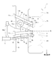
- FIG. 1 is a front view of an in-wheel motor drive wheel to which the suspension device of the first embodiment is applied as viewed from the front of the vehicle.
- FIG. 2 is a plan view of an in-wheel motor drive wheel to which the suspension device of the first embodiment is applied as viewed from above the vehicle. 1 and 2 show a straight traveling state in which the wheels are not steered.
- FIG.1 and FIG.2 show a straight traveling state in which the wheels are not steered.
- the wheel 1 disposed on the front side / right side of the vehicle body S is a front wheel steering wheel including a tire 1a and a wheel 1b on which the tire 1a is mounted on the outer periphery.
- the wheel 1b has an annular rim 1c that supports the tire 1a, and a disc-shaped wheel disc 1d provided at the center of the rim 1c.
- the wheel 1 is rotatably held on the output shaft 7b of the in-wheel motor unit 7 via the hub 2 attached to the wheel disc 1d, and can rotate about the axle Q.
- a knuckle 3 is attached to the hub 2, and a brake disc 4 is attached between the hub 2 and the wheel disc 1d.
- the brake disc 4 applies a braking force to the wheel 1 by being clamped from both sides in the vehicle width direction by a brake caliper 4A (see FIG. 2) fixed to the knuckle 3.
- the knuckle 3 includes an upper bracket 3a (see FIG. 1) that extends upward of the vehicle, a lower bracket 3b (see FIG. 1) that extends downward of the vehicle, and a steering that extends from the top to the front of the vehicle. Bracket 3c (see FIG. 2).
- the upper bracket 3a has a kingpin rotating portion 6a formed at the tip, and the kingpin rotating portion 6a is supported by the suspension structure member 10 so as to be rotatable in the turning direction (around the kingpin axis P).
- the lower bracket 3b has a lower arm support portion 6b formed at the tip thereof, and the lower arm support portion 6b can be rotated in the turning direction (around the kingpin axis P) by the suspension structure member 10, and the vehicle It is supported so that it can swing in the vertical direction.
- the steered bracket 3c has a rod connecting portion 6c (see FIG. 2) formed at the tip, and the rod connecting portion 6c is a tip of a tie rod 5A extending from a rack and pinion 5 that can be operated by a steering wheel (not shown). Is attached.
- the knuckle 3 rotates around the kingpin axis P located on the line connecting the kingpin rotating portion 6a and the lower arm supporting portion 6b, and the wheel 1 is steered. That is, the rotation of the steering wheel is converted into a stroke in the vehicle width direction by the rack and pinion 5.
- the tie rod 5A appears and disappears in the vehicle width direction.
- the tie rod 5A protrudes outward in the vehicle width direction (right side in FIG. 2)
- the front end of the knuckle 3 is pushed out toward the outer side in the vehicle width, and the wheel 1 is steered leftward.
- the tie rod 5A is pulled inward in the vehicle width direction (left side in FIG. 2), the front end of the knuckle 3 is pulled inward in the vehicle width direction, and the wheel 1 is steered rightward.
- the wheel 1 is suspended from the vehicle body S so as to be able to stroke in the vehicle vertical direction via a suspension structure member 10 for positioning the wheel 1 and a shock absorber 15 that expands and contracts in accordance with the vertical movement of the wheel 1.
- the shock absorber 15 is a so-called coil over in which the spring portion 16a and the damper 16b are coaxially arranged and integrated.
- the shock absorber 15 has an upper end 15b fixed to the vehicle body S.
- the suspension structural member 10 includes an upper suspension arm 11 (suspension arm), a lower suspension arm 12, and a third link 13 (link member).
- the upper suspension arm 11 is disposed at a position above the vehicle axle Q, and as shown in FIG. 2, the front upper arm 11a disposed on the vehicle front side with respect to the shock absorber 15 and the vehicle rear side with respect to the shock absorber 15. It has a rear upper arm 11b disposed on the side, and a connecting upper arm 11c for connecting the front upper arm 11a and the rear upper arm 11b.
- the front upper arm 11a and the rear upper arm 11b extend in the vehicle width direction, and the vehicle body side end portion 11d is supported to be swingable with respect to the vehicle body S in the vertical direction and the front-rear direction.
- connection upper arm 11c extends in the vehicle front-rear direction, and includes a wheel side end portion 11e of the front upper arm 11a, an arm connection portion 13a described later of the third link 13, and a wheel side end portion 11e of the rear upper arm 11b.
- bearings are interposed between the connection upper arm 11c and the front upper arm 11a, between the connection upper arm 11c and the third link 13, and between the connection upper arm 11c and the rear upper arm 11b.
- the front upper arm 11a, the third link 13, and the rear upper arm 11b are connected to the connecting upper arm 11c so as to be swingable in the vertical direction.
- the lower suspension arm 12 is disposed at a lower position than the axle Q, and the vehicle body side end portion 12a is supported so as to be swingable with respect to the vehicle body S in the vertical direction and the front and rear direction.
- the lower bracket 3b of the lower bracket 3b extending downward from the knuckle 3 is connected to the lower arm support 6b.
- the third link 13 is a link member that connects the wheel 1 and the upper suspension arm 11 and connects the wheel 1 and the shock absorber 15. And this 3rd link 13 has the arm connection part 13a, the wheel support part 13b, and the shock absorber connection part 13c, as shown in FIG.
- the arm connecting portion 13a is formed on the upper portion of the third link 13, and the connecting upper arm 11c of the upper suspension arm 11 passes therethrough.
- a front upper arm 11a and a rear upper arm 11b are connected to both ends of the connection upper arm 11c, respectively, and the upper suspension arm 11 has a trapezoidal shape when viewed from above.
- the third link 13 is rotationally restrained with respect to the vehicle body S and is connected to the upper suspension arm 11 in a state in which it can swing only in the vertical direction.
- the arm connecting portion 13a is disposed at a position above the tire 1a of the wheel 1 and protrudes outward in the vehicle width direction and protrudes above the tire 1a.
- the wheel support portion 13b is formed at an intermediate portion of the third link 13, and is disposed at a lower position of the vehicle than the arm connecting portion 13a.
- a kingpin rotating portion 6a formed on the upper bracket 3a of the knuckle 3 is coupled to the wheel support portion 13b so as to be rotatable around the kingpin axis P.
- the wheel 1 is supported so as to be swingable about the kingpin axis P.
- the wheel support portion 13b protrudes outward in the vehicle width direction, is disposed at a vehicle outer side position than the shock absorber connecting portion 13c, and is located inside the wheel inner region R of the wheel 1 surrounded by the rim 1c and the wheel disc 1d. (See Fig. 2).
- the shock absorber connecting portion 13c is formed at the lower portion of the third link 13, and sandwiches a mounting plate (not shown) formed at the lower end portion 15a of the shock absorber 15 and is connected via a bolt. That is, the shock absorber connecting portion 13 c is connected to the lower end portion 15 a of the shock absorber 15 so as to be swingable in the vertical direction. Further, as shown in FIG. 1, the shock absorber connecting portion 13 c is disposed at a lower position of the vehicle than the upper end 8 a (upper end portion) of the in-wheel motor unit 7. In the first embodiment, in order to avoid interference between the shock absorber 15 and the in-wheel motor unit 7, as shown in FIG.
- the shock absorber connecting portion 13c is connected to the rear end surface 8b (rear end portion) of the in-wheel motor unit 7.
- the “upper end surface 8a” is an upper surface of the unit case 7a of the in-wheel motor unit 7 that faces the upper side of the vehicle, and is the portion of the unit case 7a that is positioned at the uppermost side of the vehicle.
- the “rear end surface 8b” is a rear surface of the unit case 7a of the in-wheel motor unit 7 that faces the rear of the vehicle, and is a portion of the unit case 7a that is located at the rearmost of the vehicle.
- the unit case 7a is a substantially rectangular casing in which an unillustrated electric motor (rotary electric machine) and a reduction gear (transmission) are built.
- the upper suspension arm 11 and the shock absorber 15 are connected to the wheel 1 via the third link 13.
- the third link 13 is supported by the upper bracket 3a of the knuckle 3 at the wheel support portion 13b.
- the wheel support portion 13b is point-supported by the kingpin rotating portion 6a, and the third link 13 and the knuckle 3 can rotate relative to each other around the kingpin axis P.
- the entire third link 13 moves up and down following the vertical movement.
- the vehicle vertical load acting on the wheel 1 is input to the wheel support portion 13 b of the third link 13 via the kingpin rotating portion 6 a of the knuckle 3.
- the wheel support portion 13b is rotatable around the kingpin axis P, but is restrained in the vehicle vertical direction, so that the entire third link 13 is caused by the vehicle vertical direction load input from the wheel support portion 13b. It will move up and down.
- the lever ratio can be almost 1.
- the “lever ratio” is the ratio of the vertical stroke of the spring portion 16 a of the shock absorber 15 to the vertical stroke of the wheel 1. Thereby, it is possible to prevent the lever ratio of the shock absorber 15 from being impaired.
- the shock absorber connecting portion 13 c of the third link 13 is disposed at a position below the vehicle from the upper end surface 8 a of the in-wheel motor unit 7. That is, the lower end portion 15a of the shock absorber 15 connected to the shock absorber connecting portion 13c and the in-wheel motor unit 7 overlap (overlap) in the vehicle vertical direction.
- the lower end 15a of the shock absorber 15 can be set at a relatively low position (position close to the road surface) while avoiding interference between the shock absorber 15 and the in-wheel motor unit 7. For this reason, the entire length of the shock absorber 15 can be set to a length that can ensure a necessary stroke without setting the position of the upper end portion 15b, which is the mounting position of the shock absorber 15, to the vehicle body.
- the suspension device of the first embodiment it is not necessary to set the upper end portion 15b of the shock absorber 15 at a high position, so that the strut housing formed on the vehicle body S does not protrude upward. For this reason, it is not necessary to increase the height of the hood covering the strut housing.
- the degree of freedom of mounting the shock absorber 15 is very low.
- the lever ratio of the shock absorber 15 is greatly impaired, or the lower end portion 15a of the shock absorber 15 is set at a relatively high position. Necessity arises.
- the third link 13 is interposed between the wheel 1, the upper suspension arm 11 and the shock absorber 15, so that almost the same force as the input load from the wheel 1 is shocked. It is possible to input to the absorber 15. Therefore, the lever ratio and stroke of the shock absorber 15 can be ensured without setting the upper end portion 15b of the shock absorber 15 at a high position.
- FIG. 3 is an explanatory diagram showing a reaction force acting on the third link in the suspension device of the first embodiment.
- FIG. 4 is an explanatory view showing a reaction force acting on the third link in the suspension device of the comparative example.
- the third link reaction force receiving operation will be described with reference to FIGS. 3 and 4.
- the wheel support portion 13b of the third link 13 is disposed at a position outside the shock absorber coupling portion 13c in the vehicle width direction and at a position below the vehicle relative to the arm coupling portion 13a. That is, as shown in FIG. 3, a vehicle vertical distance X is ensured between the wheel support portion 13b and the arm connecting portion 13a, and the vehicle width is set between the wheel support portion 13b and the shock absorber connecting portion 13c. The direction distance Y is secured.
- a reaction force F acts on the third link 13 at the arm connecting portion 13a as shown by an arrow in FIG. Further, a reaction force E acts on the shock absorber connecting portion 13c.
- the reaction force F acts outward in the vehicle width direction, and the reaction force E acts downward in the vehicle. Therefore, the reaction force F and the reaction force E act to cancel each other around the wheel support portion 13b rotating around the kingpin axis P.
- the bending moment around the kingpin axis P applied to the wheel support portion 13b can be reduced, and the kingpin rotating portion 6a formed on the knuckle 3 can be reduced.
- the space around the in-wheel motor unit 7 can be expanded, and a large space that can be used for installing the in-wheel motor unit 7 can be secured.
- the position of the upper suspension arm 11 is set lower than in the case of the first embodiment, and the height of the arm connecting portion 13a of the third link 13 is substantially the same as that of the wheel support portion 13b.
- the distance X in the vehicle vertical direction cannot be ensured between the wheel support portion 13b and the arm connecting portion 13a. Therefore, as shown in FIG. 4, even if the wheel 1 moves up and down, no reaction force acts on the arm connecting portion 13a of the third link 13, and only a reaction force E directed downward in the vehicle occurs at the shock absorber connecting portion 13c. Works. As a result, the reaction force E cannot be canceled out, and the bending moment around the kingpin axis P applied to the wheel support portion 13b becomes excessive.
- the suspension structural member 10 includes a suspension arm (upper suspension arm 11) supported to be swingable with respect to the vehicle body S, and A link member (third link 13) having a shock absorber connecting portion 13c for connecting the wheel 1 to the suspension arm (upper suspension arm 11) in a swingable manner and connecting to the lower end portion 15a of the shock absorber 15;
- the shock absorber connecting portion 13c is arranged at a position below the vehicle from the upper end portion (upper end surface 8a) of the in-wheel motor unit 7.
- the suspension arm is an upper suspension arm 11 that is disposed at a position above the axle Q of the wheel 1 and supports the wheel 1 at a position above the axle Q so as to be swingable.
- the link member (third link 13) includes an arm connecting portion 13a that connects the suspension arm (upper suspension arm 11) so as to be swingable in the vertical direction, and a wheel that supports the wheel 1 so as to be swingable in the turning direction.
- a support portion 13b, The wheel support portion 13b is arranged at a position outside the shock absorber connecting portion 13c in the vehicle width direction and at a position below the vehicle than the arm connecting portion 13a. Thereby, the bending moment which acts on the wheel support part 13b can be reduced, and the installation space of the in-wheel motor unit 7 can be expanded.
- Example 2 The second embodiment is an example in which the arrangement of the third link wheel support portion and the shock absorber connecting portion is different from the first embodiment.
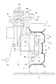
- FIG. 5 is a front view of an in-wheel motor drive wheel to which the suspension device of the second embodiment is applied as viewed from the front of the vehicle.
- FIG. 6 is a plan view of an in-wheel motor drive wheel to which the suspension device of the second embodiment is applied as viewed from above the vehicle.
- symbol is attached
- the wheel 1 is connected to the upper suspension arm 11 and the shock absorber 15 via the third link 23 (link member).
- the third link 23 includes an arm connecting portion 23a, a wheel support portion 23b, and a shock absorber connecting portion 23c.
- the wheel support portion 23b is disposed outside the wheel inner region R of the wheel 1 surrounded by the rim 1c and the wheel disc 1d, and the vehicle body side open surface (in FIG. 5) of the wheel disc 1d. Between the vehicle body S and the vehicle body S. That is, the wheel support part 23b of Example 2 is arrange
- the shock absorber connecting portion 23c is arranged at a position below the vehicle from the upper end surface 8a (upper end portion) of the in-wheel motor unit 7, and as shown in FIG.
- the motor unit 7 is disposed at an inner position in the vehicle width direction than the vehicle body side end surface 8c (vehicle body side end). That is, the shock absorber connecting portion 23 c is disposed at a position between the vehicle body S and the vehicle body side end surface 8 c of the in-wheel motor unit 7.
- the “vehicle body side end surface 8c” is a side surface of the unit case 7a of the in-wheel motor unit 7 that faces the vehicle body S, and is the portion of the unit case 7a that is closest to the vehicle body S.
- the wheel support part 23b connected with the upper bracket 3a of the knuckle 3 is arrange
- the motor volume can be expanded in the radial direction above the axle Q.
- the shock absorber connecting portion 23c is arranged around the in-wheel motor unit 7 by disposing the shock absorber connecting portion 23c between the vehicle body S and the vehicle body side end surface 8c of the in-wheel motor unit 7. It can be arranged at a position where it does not interfere. That is, the in-wheel motor unit 7 swings around the axle Q (radial direction) during driving.
- the shock absorber connecting portion 23c is disposed on the side of the in-wheel motor unit 7 in the axial direction. It becomes. Therefore, interference between the shock absorber connecting portion 23c and the in-wheel motor unit 7 when the in-wheel motor unit 7 swings can be prevented.
- the motor volume of the in-wheel motor unit 7 can be increased in the radial direction without setting the upper end portion 15b of the shock absorber 15 at a high position.
- the wheel 1 includes a rim 1c that supports the tire 1a, and a wheel disc 1d that is connected to the in-wheel motor unit 7.
- the link member (third link 23) includes a wheel support portion 23b that supports the wheel 1 so as to be swingable in a steering direction.
- the wheel support portion 23b is arranged at a position away from the wheel inner region R surrounded by the rim 1c and the wheel disc 1d. Thereby, the wheel support part 23b can be arrange
- the shock absorber connecting portion 23c is arranged at a position between the vehicle body S and a vehicle body side end portion (vehicle body side end surface 8c) of the in-wheel motor unit 7. Thereby, the shock absorber connecting portion 23c can be disposed at a position where it does not interfere with the swing of the in-wheel motor unit 7, and the motor volume can be increased in the radial direction.
- the third embodiment is an example in which the configuration of the in-wheel motor unit and the arrangement of the third link wheel support portion and the shock absorber connecting portion are different from those of the first or second embodiment.
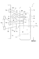
- FIG. 7 is a front view of an in-wheel motor drive wheel to which the suspension device of the third embodiment is applied as viewed from the front of the vehicle.
- FIG. 8 is a plan view of an in-wheel motor drive wheel to which the suspension device of the third embodiment is applied as viewed from above the vehicle.
- symbol is attached
- the in-wheel motor unit 7 ′ incorporates an electric motor 71 (rotary electric machine) and a speed reducer 72 in a unit case 7a. And the motor output shaft 71a of the electric motor 71 is offset with respect to the output shaft 7b of the in-wheel motor unit 7 'which is a reduction gear output shaft.
- the motor output shaft 71 a of the electric motor 71 is offset with respect to the axle Q of the wheel 1. It becomes a state.
- the motor output shaft 71a is offset with respect to the axle Q in the vehicle vertical direction and the vehicle front-rear direction. Is positioned above the vehicle from the axle Q and at the front of the vehicle from the axle Q.
- the wheel 1 is connected to the upper suspension arm 11 and the shock absorber 15 via the third link 33 (link member) as in the first and second embodiments.
- the third link 33 includes an arm connecting portion 33a, a wheel support portion 33b, and a shock absorber connecting portion 33c.
- the wheel support portion 33b is disposed outside the wheel inner region R of the wheel 1 surrounded by the rim 1c and the wheel disc 1d, that is, on the vehicle body S side, and the shock absorber connecting portion 33c. It is a vehicle front position rather than the vehicle width direction outer side position.
- the wheel support portion 33b is disposed at a vehicle rear position with respect to the rear end surface 8b (rear end portion) of the in-wheel motor unit 7 ′. That is, the wheel support portion 33b is disposed between the rear end surface 8b of the in-wheel motor unit 7 ′ and the shock absorber connecting portion 33c in the vehicle longitudinal direction. Further, the wheel support portion 33b is disposed at a position between the vehicle body side open surface of the wheel disc 1d (indicated by a dashed line A in FIG. 8) and the shock absorber connecting portion 33c in the vehicle width direction.
- the wheel support portion 33b is disposed at a position behind the vehicle relative to the motor output shaft 71a of the electric motor 71 built in the unit case 7a. That is, the motor output shaft 71a of the electric motor 71, the wheel support portion 33b, and the shock absorber connecting portion 33c are arranged in this order from the vehicle front side toward the vehicle rear side.
- the shock absorber connecting portion 33c is disposed at a position below the vehicle from the upper end surface 8a (upper end portion) of the in-wheel motor unit 7 ′, and as shown in FIG.
- the wheel motor unit 7 ' is disposed at a position behind the vehicle from the rear end surface 8b.
- the “vehicle rear position from the rear end face 8b” means that the in-wheel motor unit 7 ′ is swung around the rear end face 8b even when the in-wheel motor unit 7 ′ is swung around as the wheel 1 is steered. Point to.
- the shock absorber connecting portion 33c at the vehicle rear position with respect to the rear end face 8b of the in-wheel motor unit 7 ′, even if the in-wheel motor unit 7 ′ swings around as the wheels 1 are steered, the shock absorber Interference with the absorber connecting portion 33c can be prevented.
- the in-wheel motor unit 7 ′ is integrated with the wheel 1 that rotates around the kingpin axis P located on the line connecting the kingpin rotating portion 6 a and the lower arm support portion 6 b of the knuckle 3 when the wheel 1 is steered. Turn around. That is, the in-wheel motor unit 7 'rotates around an axis (kingpin axis P) passing through the wheel support portion 33b.
- the shock absorber connecting portion 33c is disposed so as to be positioned at the rear of the vehicle relative to the rear end surface 8b, the shock absorber connecting portion 33c is positioned below the upper end surface 8a of the in-wheel motor unit 7 ′. Even if it arrange
- the shock absorber connecting portion 33c can be arranged at a low position without considering the interference in the axle Q direction with the in-wheel motor unit 7 ′.
- the motor volume of the in-wheel motor unit 7 ′ can be increased in the axial direction without setting the upper end portion 15b of the shock absorber 15 at a high position.
- the motor output shaft 71a of the electric motor 71 of the in-wheel motor unit 7 ′ is offset with respect to the axle Q, and the wheel support portion 33b is positioned forward of the vehicle relative to the shock absorber connecting portion 33c, and It arrange
- an appropriate distance can be ensured between the in-wheel motor unit 7 ′ having relatively severe interference conditions and the shock absorber 15.
- the caster angle tilting angle of the kingpin axis P in the vehicle front-rear direction
- the kingpin inclination angle inclination angle of the kingpin axis P in the vehicle width direction
- the wheel support portion 33b can be arranged at a position behind the shock absorber connecting portion 33c. However, in that case, it becomes difficult to set the inclination angle of the kingpin shaft P that satisfies the above-described operational requirements.
- the shock absorber connecting portion 33c is made even if the in-wheel motor unit 7 'swings around when the wheel 1 is steered while maintaining the geometry of the kingpin shaft P that is appropriate from the viewpoint of the operational requirements. Can be prevented, and the motor swing space can be expanded. As a result, the motor volume of the in-wheel motor unit 7 ′ can be increased in the radial direction.
- the shock absorber connecting portion 33c is arranged at the vehicle rear position with respect to the rear end portion (rear end surface 8b) of the in-wheel motor unit 7 ′. As a result, the shock absorber connecting portion 33c can be disposed at a low position without considering interference in the axle Q direction with the in-wheel motor unit 7 ′, and the motor volume of the in-wheel motor unit 7 ′ is increased in the axial direction. can do.
- the in-wheel motor unit 7 ′ has a rotating electrical machine (electric motor 71) and an output shaft (motor output shaft 71 a) of the rotating electrical machine (electric motor 71) with respect to the axle Q of the wheel 1.
- the link member (third link 33) includes a wheel support portion 33b that supports the wheel 1 so as to be swingable in a steering direction.
- the wheel support portion 33b is disposed at a vehicle front position and a vehicle width direction outer position than the shock absorber connecting portion 33c, and more than an output shaft (motor output shaft 71a) of the rotating electrical machine (electric motor 71). It was set as the structure arrange
- the fourth embodiment is an example in which the arrangement of the third link wheel support portion and the shock absorber connection portion is different from the first to third embodiments.
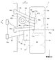
- FIG. 9 is a front view of an in-wheel motor drive wheel to which the suspension device of the fourth embodiment is applied as viewed from the front of the vehicle.
- FIG. 10 is a plan view of an in-wheel motor drive wheel to which the suspension device of the fourth embodiment is applied as viewed from above the vehicle. Note that the same components as those in the first to third embodiments are denoted by the same reference numerals, and detailed description thereof is omitted.
- the in-wheel motor unit 7 ′ incorporates the electric motor 71 (rotating electric machine) and the speed reducer 72 in the unit case 7a.
- the motor output shaft 71a of the electric motor 71 is offset with respect to the output shaft 7b of the in-wheel motor unit 7 ′.
- the wheel 1 is connected to the upper suspension arm 11 and the shock absorber 15 via the third link 43 (link member) as in the first to third embodiments.
- the third link 43 includes an arm connecting portion 43a, a wheel support portion 43b, and a shock absorber connecting portion 43c.
- the wheel support portion 43b is disposed outside the wheel inner region R of the wheel 1 surrounded by the rim 1c and the wheel disc 1d, and more than the shock absorber connecting portion 43c. It is a vehicle front position and is disposed at a position outside the vehicle width direction. Further, the wheel support portion 43 b is disposed at a vehicle rear position with respect to the motor output shaft 71 a of the electric motor 71.
- the vehicle longitudinal dimension ⁇ from the shock absorber connecting portion 43c to the wheel support portion 43b is set, and the vehicle width direction size from the shock absorber connecting portion 43c to the wheel support portion 43b is set. It is set to be shorter than ⁇ . That is, the vehicle longitudinal direction dimension ⁇ between the shock absorber connecting portion 43c and the wheel support portion 43b is shorter than the vehicle width direction dimension (vehicle lateral direction dimension) ⁇ .
- the vehicle longitudinal direction dimension ⁇ from the shock absorber connecting portion 43c to the wheel support portion 43b is an in-wheel motor when the wheel 1 is turned to the outer wheel side when steered, as shown by a one-dot chain line in FIG. It depends on the interference requirement between the vehicle body side end face 8c of the unit 7 'and the shock absorber 15. That is, the vehicle longitudinal dimension ⁇ is set to the closest dimension in a state where the vehicle body side end face 8c of the in-wheel motor unit 7 ′ and the shock absorber 15 do not interfere when the outer wheel of the wheel 1 is steered.
- the vehicle width direction dimension ⁇ from the shock absorber connecting portion 43c to the wheel support portion 43b is, as shown by a two-dot chain line in FIG. 11, the wheel 1b when the wheel 1 becomes the inner ring side when turning. It depends on the interference requirement between the vehicle body side open surface (indicated by A in FIG. 11) and the shock absorber 15. That is, the vehicle width direction dimension ⁇ is set to the closest dimension when the vehicle body side open surface A of the wheel 1b and the shock absorber 15 do not interfere when the inner wheel of the wheel 1 is steered.
- the outer ring turning radius is larger than the inner ring turning radius.
- the inner wheel turning amount inner wheel turning angle
- the outer wheel turning amount outer wheel turning angle
- the Ackermann ratio difference between the inner wheel turning angle and the outer wheel turning angle
- the inner wheel turning amount may be set to be appropriately larger than the outer wheel turning amount. preferable.
- the inner wheel turning amount is generally set larger than the outer wheel turning amount. Therefore, the interference requirement between the vehicle body side open surface A of the wheel 1b and the shock absorber 15 at the time of inner wheel steering is the interference between the vehicle body side end surface 8c of the in-wheel motor unit 7 'and the shock absorber 15 at the time of outer wheel steering. It will be stricter than the requirement.
- the vehicle longitudinal direction dimension ⁇ between the shock absorber coupling portion 43c and the wheel support portion 43b is made shorter than the vehicle width direction dimension (vehicle lateral direction dimension) ⁇ . While preventing interference with the shock absorber 15, it is possible to secure the maximum space in which the in-wheel motor unit 7 'can swing around. Thereby, the motor volume of in-wheel motor unit 7 'can be increased to radial direction.
- the fifth embodiment is an example in which the arrangement of the kingpin shaft is different from that of the first to fourth embodiments.
- FIG. 12 is a front view of an in-wheel motor drive wheel to which the suspension device of the fifth embodiment is applied as viewed from the front of the vehicle.
- FIG. 13A is a plan view of an in-wheel motor drive wheel to which the suspension device of the fifth embodiment is applied as viewed from above the vehicle, and
- FIG. 13B is an in-wheel motor drive of a comparative example when the scrub radius is not zero. It is a top view when a wheel is seen from the vehicle upper part.
- symbol is attached
- the suspension structural member 10 includes an upper suspension arm 11 that supports the wheel 1 at a position above the vehicle from the axle Q and a wheel at a position below the vehicle from the axle Q. 1, a lower suspension arm 12 that supports 1 and a third link 53 (link member).
- the third link 53 includes an arm connecting portion 53a, a wheel support portion 53b, and a shock absorber connecting portion 53c.
- the wheel 1 is connected to the upper suspension arm 11 and the shock absorber via the third link 53. 15 is connected. Further, as shown in FIG. 12, the shock absorber connecting portion 53 c is disposed at a position below the vehicle with respect to the upper end surface 8 a of the in-wheel motor unit 7.
- the kingpin shaft P located on the line connecting the kingpin rotating portion 6a formed on the knuckle 3 and the lower arm support portion 6b is disposed at a position where the scrub radius becomes zero. Yes.
- the wheel support portion 53b of the third link 53 is connected to the kingpin rotating portion 6a.
- the lower arm support portion 6 b is a support position where the wheel 1 is supported by the lower suspension arm 12. That is, the “kingpin axis P” is set by the wheel support portion 53 b and the support position at which the wheel 1 is supported by the lower suspension arm 12.
- the “scrub radius” is a distance from the point where the kingpin axis P intersects the road surface G to the ground contact center of the tire 1a when the vehicle is viewed from the front (the state shown in FIG. 12). In FIG. 12, since this scrub radius is zero, this scrub radius is indicated by a point O. Note that “making the scrub radius zero” includes not only a state where the radius is strictly zero but also an error that can be ignored.
- the kingpin axis P is arranged so that the scrub radius becomes zero. Therefore, the torque generated around the kingpin axis P can be made almost zero. That is, the driving force (braking force) F applied to the wheel 1 by the in-wheel motor unit 7 is input to the ground contact point W of the tire 1a shown in FIG. 13A.
- the torque generated around the kingpin axis P is obtained by the product of the ground point input driving force (ground point input braking force) and the scrub radius. Therefore, if the scrub radius is set to zero, the torque generated around the kingpin axis P is substantially zero.
- the suspension structural member 10 is swingably supported with respect to the vehicle body S, and is disposed at a position below the axle Q of the wheel 1, and at the position below the vehicle below the axle Q.
- the wheel support portion 53b is disposed at a position higher than the axle Q of the wheel 1, and the wheel support portion 53b and the lower suspension arm 12 support the wheel 1 (lower arm support portion).
- the kingpin axis P set by 6b is arranged at a position where the scrub radius O becomes zero. Thereby, the torque generated around the kingpin axis P can be made substantially zero, and torque steer or the like when a difference occurs in the braking / driving force applied to the left and right wheels 1 can be suppressed.
- the present invention is not limited to this.
- the present invention can also be applied to drive wheels arranged on the rear side of the vehicle body S.
- the suspension device of the present invention by applying the suspension device of the present invention, the stroke of the shock absorber can be ensured while preventing the shock absorber from protruding into the cargo compartment.
- the suspension devices of the above embodiments are all of the double wishbone type, but are not limited to this, and may be a uniaxial arm suspension device such as a trailing arm type.
- the in-wheel motor unit 7 and 7 becomes a structure which incorporates the electric motor 71 and the reduction gear (transmission) 72 integrally in the motor case 7a, an electric motor and a reduction gear are included. (Transmission) may be separated.
Abstract
Description
そのため、インホイールモータユニットの配置スペースを確保するためには、ショックアブソーバの下端部と下側サスペンションアームとの連結位置を、車輪のホイルセンタから離間させ、車体側に配置する必要がある。しかしながら、これにより、ショックアブソーバのレバー比が低下してしまうという問題が生じてしまう。
しかも、下側サスペンションアームは、通常車体側の端部が車輪側の端部よりも車両上方に配置されている。そのため、ショックアブソーバの下端部と下側サスペンションアームとの連結位置を車体側に配置するほど、ショックアブソーバの下端部が車両上方に配置されることになる。そのため、ショックアブソーバの全長を維持すれば、ショックアブソーバの上端が車両上方に突出するし、車両上方への突出を抑えるためにショックアブソーバの全長を短縮すればストローク不足が生じるという問題が発生してしまう。
前記サスペンションアームは、車体に対して揺動可能に支持される。
前記リンク部材は、前記サスペンションアームに前記車輪を揺動可能に連結すると共に、前記ショックアブソーバの下端部に連結するショックアブソーバ連結部を有する。
そして、前記ショックアブソーバ連結部を、前記インホイールモータユニットの上端部よりも車両下方位置に配置する。
すなわち、インホイールモータユニットの配置スペースを確保するため、ショックアブソーバの下端部を、車輪のホイルセンタから離間させて車体側に配置した場合であっても、レバー比をほぼ1とすることができる。そのため、ショックアブソーバのレバー比を損なうことを防止できる。
さらに、リンク部材とショックアブソーバの下端部との連結位置であるショックアブソーバ連結部が、インホイールモータユニットの上端部よりも車両下方位置に配置される。これにより、ショックアブソーバの支持位置を比較的低い位置に設定することができる。そのため、ショックアブソーバの上端位置を高くしなくても、ショックアブソーバの全長を大きくすることができ、必要なストロークを確保することができる。
この結果、ショックアブソーバの上端部を高い位置に設定することなく、ショックアブソーバのレバー比及びストロークを確保することができる。
まず、構成を説明する。
実施例1におけるインホイールモータ駆動車輪に搭載されたサスペンション装置(インホイールモータ駆動車輪用サスペンション装置)の構成を、「全体の構成」、「サスペンション構造部材の構成」、「サードリンクの構成」に分けて説明する。
図1は、実施例1のサスペンション装置が適用されたインホイールモータ駆動車輪を車両前方から見たときの正面図である。図2は、実施例1のサスペンション装置が適用されたインホイールモータ駆動車輪を車両上方から見たときの平面図である。なお、図1及び図2は、車輪が転舵していない直進状態を示す。以下、図1及び図2に基づき、実施例1のサスペンション装置の全体構成を説明する。
前記上側ブラケット3aは、先端部にキングピン回転部6aが形成され、このキングピン回転部6aは、サスペンション構造部材10によって転舵方向(キングピン軸P回り)に回動可能に支持されている。前記下側ブラケット3bは、先端部にロアアーム支持部6bが形成され、このロアアーム支持部6bは、サスペンション構造部材10によって転舵方向(キングピン軸P回り)に回動可能であって、且つ、車両上下方向に揺動可能に支持されている。前記転舵ブラケット3cは、先端部にロッド連結部6c(図2参照)が形成され、このロッド連結部6cは、図外のステアリングホイルにより操作可能なラックアンドピニオン5から延びるタイロッド5Aの先端部が取り付けられている。これにより、ドライバーがステアリングホイルを回転させると、ナックル3がキングピン回転部6aとロアアーム支持部6bとを結んだ線上に位置するキングピン軸P回りに回転し、車輪1が転舵される。
すなわち、ステアリングホイルの回転がラックアンドピニオン5によって車幅方向のストロークに変換される。これにより、タイロッド5Aが車幅方向に出没する。そして、タイロッド5Aが車幅方向外側(図2において右側)に突出したときには、ナックル3の前端部が車幅方向外側に向かって押し出され、車輪1が左方向に転舵される。また、タイロッド5Aが車幅方向内側(図2において左側)に引き込まれたときには、ナックル3の前端部が車幅方向内側に向かって引っ張られ、車輪1が右方向に転舵される。
なお、実施例1では、ショックアブソーバ15は、スプリング部16aと、ダンパー16bが同軸配置されて一体化した、いわゆるコイルオーバーである。このショックアブソーバ15は、上端部15bが車体Sに固定されている。
前記サスペンション構造部材10は、図1に示すように、アッパーサスペンションアーム11(サスペンションアーム)と、ロアサスペンションアーム12と、サードリンク13(リンク部材)と、を備えている。
前記前側アッパーアーム11a及び前記後側アッパーアーム11bは、それぞれ車幅方向に延在され、車体側端部11dが車体Sに対して上下方向及び前後方向に揺動可能に支持されている。
前記連結アッパーアーム11cは、車両前後方向に延在され、前側アッパーアーム11aの車輪側端部11eと、サードリンク13の後述するアーム連結部13aと、後側アッパーアーム11bの車輪側端部11eを、車両前方から順に貫通している(図2参照)。このとき、連結アッパーアーム11cと前側アッパーアーム11aの間、連結アッパーアーム11cとサードリンク13の間、連結アッパーアーム11cと後側アッパーアーム11bの間、のそれぞれには図示しないベアリングが介在されている。そして、連結アッパーアーム11cに対し、前側アッパーアーム11a、サードリンク13、後側アッパーアーム11bは、それぞれ上下方向に揺動可能に連結されている。
前記サードリンク13は、図1に示すように、車輪1とアッパーサスペンションアーム11を連結すると共に、車輪1とショックアブソーバ15を連結するリンク部材である。
そして、このサードリンク13は、図1に示すように、アーム連結部13aと、車輪支持部13bと、ショックアブソーバ連結部13cと、を有している。
さらに、この車輪支持部13bは、車幅方向外側に突出し、ショックアブソーバ連結部13cよりも車両外側位置に配置されると共に、リム1c及びホイールディスク1dによって囲まれる車輪1のホイール内側領域Rの内側に入り込んでいる(図2参照)。
さらに、このショックアブソーバ連結部13cは、図1に示すように、インホイールモータユニット7の上端8a(上端部)よりも車両下方位置に配置されている。
また、実施例1では、ショックアブソーバ15とインホイールモータユニット7との干渉を避けるため、図2に示すように、ショックアブソーバ連結部13cをインホイールモータユニット7の後端面8b(後端部)よりも車両後方位置に配置している。
ここで、「上端面8a」とは、インホイールモータユニット7のユニットケース7aの車両上方に臨む上面であり、ユニットケース7aのうち最も車両上方に位置する部分である。また、「後端面8b」とは、インホイールモータユニット7のユニットケース7aの車両後方に臨む後面であり、ユニットケース7aのうち最も車両後方に位置する部分である。なお、ユニットケース7aは、不図示の電動モータ(回転電機)と減速機(変速機)を内蔵するほぼ矩形の筐体である。
実施例1のサスペンション装置では、サードリンク13を介して、車輪1に対し、アッパーサスペンションアーム11と、ショックアブソーバ15を連結している。また、このサードリンク13は、車輪支持部13bにおいて、ナックル3の上側ブラケット3aに支持されている。このとき、車輪支持部13bは、キングピン回転部6aに点支持されており、サードリンク13とナックル3は、キングピン軸P回りに互いに相対回転可能となっている。
実施例1のサスペンション装置では、図1に示すように、サードリンク13のショックアブソーバ連結部13cが、インホイールモータユニット7の上端面8aよりも車両下方位置に配置されている。すなわち、ショックアブソーバ連結部13cに連結したショックアブソーバ15の下端部15aと、インホイールモータユニット7とは、車両上下方向にオーバーラップ(重複)している。
図3は、実施例1のサスペンション装置においてサードリンクに作用する反力を示した説明図である。図4は、比較例のサスペンション装置においてサードリンクに作用する反力を示した説明図である。以下、図3及び図4に基づき、サードリンク反力受け作用について説明する。
つまり、図3に示すように、車輪支持部13bとアーム連結部13aとの間に、車両上下方向の距離Xを確保し、車輪支持部13bとショックアブソーバ連結部13cとの間に、車幅方向の距離Yを確保している。
そのため、図4に示すように、車輪1が上下動しても、サードリンク13のアーム連結部13aには反力が作用せず、ショックアブソーバ連結部13cにおいてのみ車両下方に向かう反力Eが作用する。
これにより、反力Eを相殺することができず、車輪支持部13bにかかるキングピン軸P回りの曲げモーメントが過大になってしまう。このため、ナックル3に形成されるキングピン回転部6aにかかる負担が大きくなるので、このキングピン回転部6aを大きく形成する必要が生じる。この結果、インホイールモータユニット7の設置に利用できるスペースが縮小してしまうという問題が生じる。
実施例1のインホイールモータ駆動車輪用サスペンション装置にあっては、下記に列挙する効果を得ることができる。
前記サスペンション構造部材10は、車体Sに対して揺動可能に支持されるサスペンションアーム(アッパーサスペンションアーム11)と、
前記サスペンションアーム(アッパーサスペンションアーム11)に前記車輪1を揺動可能に連結すると共に、前記ショックアブソーバ15の下端部15aに連結するショックアブソーバ連結部13cを有するリンク部材(サードリンク13)と、
を備え、
前記ショックアブソーバ連結部13cを、前記インホイールモータユニット7の上端部(上端面8a)よりも車両下方位置に配置する構成とした。
これにより、ショックアブソーバ15の上端部15bを高い位置に設定することなく、ショックアブソーバ15のレバー比及びストロークを確保することができる。
前記リンク部材(サードリンク13)は、前記サスペンションアーム(アッパーサスペンションアーム11)を上下方向に揺動可能に連結するアーム連結部13aと、前記車輪1を転舵方向に揺動可能に支持する車輪支持部13bと、を有し、
前記車輪支持部13bを、前記ショックアブソーバ連結部13cよりも車幅方向外側位置であって、前記アーム連結部13aよりも車両下方位置に配置する構成とした。
これにより、車輪支持部13bに作用する曲げモーメントを低減し、インホイールモータユニット7の設置スペースの拡大を図ることができる。
実施例2は、サードリンクの車輪支持部及びショックアブソーバ連結部の配置を、実施例1とは異なる構成とした例である。
ここで、「車体側端面8c」とは、インホイールモータユニット7のユニットケース7aの車体Sに臨む側面であり、ユニットケース7aのうち最も車体Sに近接した部分である。
そのため、インホイールモータユニット7の振れ回り時における、ショックアブソーバ連結部23cとインホイールモータユニット7との干渉を防止することができる。
そしてこれにより、ショックアブソーバ15の上端部15bを高い位置に設定することなく、インホイールモータユニット7のモータ体積を径方向に増大することができる。
実施例2のインホイールモータ駆動車輪用サスペンション装置にあっては、下記に列挙する効果を得ることができる。
前記リンク部材(サードリンク23)は、前記車輪1を転舵方向に揺動可能に支持する車輪支持部23bを有し、
前記車輪支持部23bを、前記リム1c及び前記ホイールディスク1dで囲まれるホイール内側領域Rから外れた位置に配置する構成とした。
これにより、車輪支持部23bをインホイールモータユニット7が配置されるホイール内側領域Rの外側に配置することができ、モータ体積の増大を図ることができる。
これにより、ショックアブソーバ連結部23cをインホイールモータユニット7の振れ回りに干渉しない位置に配置でき、モータ体積を径方向に増大することができる。
実施例3は、インホイールモータユニットの構成と、サードリンクの車輪支持部及びショックアブソーバ連結部の配置を、実施例1又は実施例2とは異なる構成とした例である。
つまり、車輪支持部33bは、車両前後方向において、インホイールモータユニット7´の後端面8bとショックアブソーバ連結部33cとの間に配置される。また、この車輪支持部33bは、車幅方向において、ホイールディスク1dの車体側開放面(図8において一点鎖線Aで示す)とショックアブソーバ連結部33cの間の位置に配置される。
すなわち、車両前方側から車両後方に向けて、電動モータ71のモータ出力軸71a、車輪支持部33b、ショックアブソーバ連結部33cの順に並ぶこととなる。
なお、「後端面8bよりも車両後方位置」とは、車輪1の転舵に伴ってインホイールモータユニット7´が振れ回った状態でも、後端面8bよりも車両後方位置に配置されることを指す。
これに対し、後端面8bよりも車両後方位置となるようにショックアブソーバ連結部33cを配置しているので、このショックアブソーバ連結部33cをインホイールモータユニット7´の上端面8aよりも車両下方位置に配置しても、車輪支持部33b回りにインホイールモータユニット7´が振れ回ったときにユニットケース7aと干渉することはない。
実施例3のインホイールモータ駆動車輪用サスペンション装置にあっては、下記に列挙する効果を得ることができる。
これにより、インホイールモータユニット7´との車軸Q方向の干渉を考慮することなくショックアブソーバ連結部33cを低い位置に配置することができ、インホイールモータユニット7´のモータ体積を軸方向に増大することができる。
前記リンク部材(サードリンク33)は、前記車輪1を転舵方向に揺動可能に支持する車輪支持部33bを有し、
前記車輪支持部33bを、前記ショックアブソーバ連結部33cよりも車両前方位置、且つ、車幅方向外側位置に配置すると共に、前記回転電機(電動モータ71)の出力軸(モータ出力軸71a)よりも車両後方位置に配置する構成とした。
これにより、操安要件の観点から適切なキングピン軸Pのジオメトリとしつつ、モータ振れ回り空間の拡大を図ることができ、インホイールモータユニット7´のモータ体積を径方向に増大することができる。
実施例4は、サードリンクの車輪支持部及びショックアブソーバ連結部の配置を、実施例1から実施例3とは異なる構成とした例である。
すなわち、ショックアブソーバ連結部43cと車輪支持部43bとの間の車両前後方向寸法αが、車幅方向寸法(車両左右方向寸法)βよりも短くなっている。
実施例4のインホイールモータ駆動用サスペンション装置にあっては、下記に挙げる効果を得ることができる。
これにより、旋回時の車輪1とショックアブソーバ15との干渉を防止しつつ、インホイールモータユニット7´の振れ回り可能空間を最大限確保でき、モータ体積を径方向に増大することができる。
実施例5は、キングピン軸の配置を、実施例1~実施例4とは異なる構成にした例である。
また、「スクラブ半径」とは、車両を正面から見たとき(図12に示す状態)、キングピン軸Pが路面Gと交差する点から、タイヤ1aの接地中心までの距離である。なお、図12では、このスクラブ半径がゼロであるため、このスクラブ半径を点Oによって示す。
なお、「スクラブ半径をゼロにする」とは、厳密にゼロとなる状態だけでなく、無視できる程度の誤差を含む。
すなわち、インホイールモータユニット7によって車輪1に付与される駆動力(制動力)Fは、図13Aに示すタイヤ1aの接地点Wに入力する。一方、キングピン軸P回りに発生するトルクは、接地点入力駆動力(接地点入力制動力)とスクラブ半径との積で求められる。そのため、スクラブ半径をゼロにすれば、キングピン軸P回りに発生するトルクは概ねゼロになる。
しかしながら、左右の車輪1間において、走行中に発生する左右の車輪1の輪荷重変動、左右独立のトラクション制御、アンチロックブレーキ制御、ヨーモーメント制御等の影響により、駆動力(制動力)差は多くの場面で存在する。そして、この駆動力(制動力)左右差によって、左右のキングピン軸P回りのトルクが異なり、ステアリングラック軸力への外乱やトルクステアが発生してしまう。そのため、制駆動力条件によってはステアリングラック軸力への外乱等が大きくなってしまうという問題が生じていた。
実施例5のインホイールモータ駆動車輪用サスペンション装置にあっては、下記に挙げる効果を得ることができる。
前記車輪支持部53bを、前記車輪1の車軸Qよりも車両上方位置に配置すると共に、前記車輪支持部53b、及び、前記ロアサスペンションアーム12によって前記車輪1を支持する支持位置(ロアアーム支持部)6bによって設定されるキングピン軸Pを、スクラブ半径Oがゼロとなる位置に配置する構成とした。
これにより、キングピン軸P回りに発生するトルクを概ねゼロにすることができ、左右の車輪1に付与される制駆動力に差が生じた際のトルクステア等を抑制することができる。
ここで、後輪駆動のインホイールモータ駆動車において、ショックアブソーバの下端位置を路面から離れた高い位置に設定してしまうと、その分、ショックアブソーバの上端が車両後部に形成される荷室内に突出してしまい、荷室が狭くなるという問題が生じる。
これに対し、本発明のサスペンション装置を適用することで、荷室へのショックアブソーバの突出を防止しつつ、ショックアブソーバのストロークを確保することができる。
Claims (8)
- インホイールモータユニットにより駆動する車輪を、サスペンション構造部材及びショックアブソーバを介して車体に懸架するインホイールモータ駆動車輪用サスペンション装置において、
前記サスペンション構造部材は、車体に対して揺動可能に支持されるサスペンションアームと、
前記サスペンションアームに前記車輪を揺動可能に連結すると共に、前記ショックアブソーバの下端部に連結するショックアブソーバ連結部を有するリンク部材と、
を備え、
前記ショックアブソーバ連結部を、前記インホイールモータユニットの上端部よりも車両下方位置に配置する
ことを特徴とするインホイールモータ駆動車輪用サスペンション装置。 - 請求項1に記載されたインホイールモータ駆動車輪用サスペンション装置において、
前記車輪は、タイヤを支持するリムと、前記インホイールモータユニットに連結されるホイールディスクと、を有し、
前記リンク部材は、前記車輪を転舵方向に揺動可能に支持する車輪支持部を有し、
前記車輪支持部を、前記リム及び前記ホイールディスクで囲まれるホイール内側領域から外れた位置に配置する
ことを特徴とするインホイールモータ駆動車輪用サスペンション装置。 - 請求項1又は請求項2に記載されたインホイールモータ駆動車輪用サスペンション装置において、
前記ショックアブソーバ連結部を、前記車体と、前記インホイールモータユニットの車体側端部と、の間の位置に配置する
ことを特徴とするインホイールモータ駆動車輪用サスペンション装置。 - 請求項1から請求項3のいずれか一項に記載されたインホイールモータ駆動車輪用サスペンション装置において、
前記ショックアブソーバ連結部を、前記インホイールモータユニットの後端部よりも車両後方位置に配置する
ことを特徴とするインホイールモータ駆動車輪用サスペンション装置。 - 請求項1から請求項4のいずれか一項に記載されたインホイールモータ駆動車輪用サスペンション装置において、
前記インホイールモータユニットは、回転電機を有すると共に、前記回転電機の出力軸を、前記車輪の車軸に対してオフセットさせ、
前記リンク部材は、前記車輪を転舵方向に揺動可能に支持する車輪支持部を有し、
前記車輪支持部を、前記ショックアブソーバ連結部よりも車両前方位置、且つ、車幅方向外側位置に配置すると共に、前記回転電機の出力軸よりも車両後方位置に配置する
ことを特徴とするインホイールモータ駆動車輪用サスペンション装置。 - 請求項5に記載されたインホイールモータ駆動車輪用サスペンション装置において、
前記ショックアブソーバ連結部から前記車輪支持部までの車両前後方向寸法を、前記ショックアブソーバ連結部から前記車輪支持部までの車幅方向寸法よりも短く設定する
ことを特徴とするインホイールモータ駆動車輪用サスペンション装置。 - 請求項1から請求項6のいずれか一項に記載されたインホイールモータ駆動車輪用サスペンション装置において、
前記サスペンションアームは、前記車輪の車軸よりも車両上方位置に配置され、前記車軸よりも車両上方位置で前記車輪を揺動可能に支持するアッパーサスペンションアームであり、
前記リンク部材は、前記サスペンションアームを上下方向に揺動可能に連結するアーム連結部と、前記車輪を転舵方向に揺動可能に支持する車輪支持部をと、を有し、
前記車輪支持部を、前記ショックアブソーバ連結部よりも車幅方向外側位置であって、前記アーム連結部よりも車両下方位置に配置する
ことを特徴とするインホイールモータ駆動車輪用サスペンション装置。 - 請求項7に記載されたインホイールモータ駆動車輪用サスペンション装置において、
前記サスペンション構造部材は、前記車体に対して揺動可能に支持されると共に、前記車輪の車軸よりも車両下方位置に配置され、前記車軸よりも車両下方位置で前記車輪を揺動可能に支持するロアサスペンションアームを備え、
前記車輪支持部を、前記車輪の車軸よりも車両上方位置に配置すると共に、前記車輪支持部、及び、前記ロアサスペンションアームによって前記車輪を支持する支持位置によって設定されるキングピン軸を、スクラブ半径がゼロとなる位置に配置する
ことを特徴とするインホイールモータ駆動車輪用サスペンション装置。
Priority Applications (4)
| Application Number | Priority Date | Filing Date | Title |
|---|---|---|---|
| JP2015514787A JP6004097B2 (ja) | 2013-04-30 | 2014-03-31 | インホイールモータ駆動車輪用サスペンション装置 |
| CN201480024424.XA CN105163961B (zh) | 2013-04-30 | 2014-03-31 | 轮内电动机驱动车轮用悬架装置 |
| US14/781,162 US9731572B2 (en) | 2013-04-30 | 2014-03-31 | Suspension device for an in-wheel motor driven wheel |
| EP14792287.6A EP2993066B1 (en) | 2013-04-30 | 2014-03-31 | Suspension device for in-wheel motor driven wheel |
Applications Claiming Priority (2)
| Application Number | Priority Date | Filing Date | Title |
|---|---|---|---|
| JP2013-095798 | 2013-04-30 | ||
| JP2013095798 | 2013-04-30 |
Publications (1)
| Publication Number | Publication Date |
|---|---|
| WO2014178250A1 true WO2014178250A1 (ja) | 2014-11-06 |
Family
ID=51843385
Family Applications (1)
| Application Number | Title | Priority Date | Filing Date |
|---|---|---|---|
| PCT/JP2014/059451 WO2014178250A1 (ja) | 2013-04-30 | 2014-03-31 | インホイールモータ駆動車輪用サスペンション装置 |
Country Status (5)
| Country | Link |
|---|---|
| US (1) | US9731572B2 (ja) |
| EP (1) | EP2993066B1 (ja) |
| JP (1) | JP6004097B2 (ja) |
| CN (1) | CN105163961B (ja) |
| WO (1) | WO2014178250A1 (ja) |
Cited By (2)
| Publication number | Priority date | Publication date | Assignee | Title |
|---|---|---|---|---|
| WO2015129379A1 (ja) * | 2014-02-27 | 2015-09-03 | Ntn株式会社 | インホイールモータ駆動装置とダンパとの連結構造およびこの連結構造を備えるサスペンション装置 |
| JP2017065321A (ja) * | 2015-09-28 | 2017-04-06 | Ntn株式会社 | インホイールモータ駆動装置とストラット式サスペンション装置の連結構造 |
Families Citing this family (17)
| Publication number | Priority date | Publication date | Assignee | Title |
|---|---|---|---|---|
| JP6382597B2 (ja) * | 2014-06-27 | 2018-08-29 | Ntn株式会社 | 車両 |
| WO2016134699A1 (de) * | 2015-02-27 | 2016-09-01 | Ksm Castings Group Gmbh | Radträger |
| US9969228B2 (en) * | 2016-09-29 | 2018-05-15 | David R. Hall | Vehicle inboard suspension system |
| JP6823418B2 (ja) * | 2016-09-30 | 2021-02-03 | Ntn株式会社 | インホイールモータ駆動装置 |
| JP6125083B1 (ja) * | 2016-10-17 | 2017-05-10 | Ntn株式会社 | インホイールモータ駆動装置 |
| CN106627102A (zh) * | 2017-02-10 | 2017-05-10 | 中国第汽车股份有限公司 | 一种轮毂电机驱动装置 |
| DE102018206402B4 (de) * | 2018-04-25 | 2021-08-19 | Audi Ag | Radaufhängung für ein Kraftfahrzeug sowie entsprechendes Kraftfahrzeug |
| US10703192B2 (en) * | 2018-06-11 | 2020-07-07 | Rivian Ip Holdings, Llc | Vehicle driveline with articulating wheel motors |
| WO2020097661A1 (en) * | 2018-11-15 | 2020-05-22 | Applied Electric Vehicles Pty Ltd | Vehicle suspension and drive mechanism with virtual steering pivot |
| LU101110B1 (en) | 2019-01-29 | 2020-07-29 | Alpha Ec Ind 2018 S A R L | Low platform bus with steering modules |
| LU101111B1 (en) | 2019-01-29 | 2020-07-29 | Alpha Ec Ind 2018 S A R L | Bus steering system |
| JP7188273B2 (ja) | 2019-05-13 | 2022-12-13 | トヨタ自動車株式会社 | 車両用サスペンション装置 |
| JP7120149B2 (ja) * | 2019-05-13 | 2022-08-17 | トヨタ自動車株式会社 | 車両用サスペンション装置 |
| KR20220035593A (ko) * | 2020-09-14 | 2022-03-22 | 현대자동차주식회사 | 독립 현가 시스템 |
| US11970231B2 (en) * | 2021-05-13 | 2024-04-30 | Toyota Motor Engineering & Manufacturing North America, Inc. | Causing a difference between steering angles of front wheels or rear wheels of a vehicle in a park mode |
| KR20230060647A (ko) | 2021-10-28 | 2023-05-08 | 현대자동차주식회사 | 독립 코너모듈 |
| DE102022202016B3 (de) * | 2022-02-28 | 2023-06-07 | Zf Friedrichshafen Ag | Radaufhängung für ein Rad eines Fahrzeugs |
Citations (6)
| Publication number | Priority date | Publication date | Assignee | Title |
|---|---|---|---|---|
| JPH03112724A (ja) * | 1989-09-25 | 1991-05-14 | Aisin Aw Co Ltd | 車両用モータの配線および配管装置 |
| JP2004122953A (ja) | 2002-10-02 | 2004-04-22 | Bridgestone Corp | 操舵輪用インホイールモータシステム |
| JP2004161157A (ja) * | 2002-11-14 | 2004-06-10 | Honda Motor Co Ltd | 電動機付き車両 |
| JP2008168804A (ja) * | 2007-01-12 | 2008-07-24 | Mazda Motor Corp | 車両用駆動装置の配設構造 |
| JP2010228544A (ja) * | 2009-03-26 | 2010-10-14 | Nissan Motor Co Ltd | 車両用サスペンション装置 |
| JP2013144509A (ja) * | 2012-01-16 | 2013-07-25 | Nissan Motor Co Ltd | インホイールモータ駆動車輪のモータ給電線配索構造 |
Family Cites Families (20)
| Publication number | Priority date | Publication date | Assignee | Title |
|---|---|---|---|---|
| BE1013399A3 (nl) * | 2000-04-20 | 2001-12-04 | Hool Nv Van | Verbeterde voorwielophanging voor bussen en dergelijke. |
| DE602004023387D1 (de) * | 2003-05-14 | 2009-11-12 | Toyota Motor Co Ltd | Aufhängungssystem für ein elektrisches kraftfahrzeug |
| JP4225134B2 (ja) * | 2003-06-25 | 2009-02-18 | トヨタ自動車株式会社 | 車両用懸架装置 |
| JP4113506B2 (ja) * | 2003-09-30 | 2008-07-09 | トヨタ自動車株式会社 | 車輪支持装置 |
| JP4276579B2 (ja) * | 2004-05-17 | 2009-06-10 | トヨタ自動車株式会社 | インホイールモータに設けられる部品の搭載構造 |
| JP4442315B2 (ja) * | 2004-05-18 | 2010-03-31 | トヨタ自動車株式会社 | 電動輪 |
| JP4779582B2 (ja) * | 2005-11-10 | 2011-09-28 | 日産自動車株式会社 | インホイールドライブユニットのサスペンション装置 |
| JP2007161022A (ja) * | 2005-12-12 | 2007-06-28 | Bridgestone Corp | インホイールモータシステム |
| JP4820189B2 (ja) * | 2006-03-09 | 2011-11-24 | 本田技研工業株式会社 | 車両用ホイール駆動装置の配置構造 |
| JP2009202606A (ja) * | 2008-02-26 | 2009-09-10 | Nissan Motor Co Ltd | 車両用操舵装置 |
| WO2010122837A1 (ja) * | 2009-04-21 | 2010-10-28 | 本田技研工業株式会社 | サスペンション装置 |
| JP5325653B2 (ja) * | 2009-05-19 | 2013-10-23 | 東海ゴム工業株式会社 | 電動モータ駆動式車両用の駆動ユニット防振保持装置 |
| DE102011011011A1 (de) * | 2010-02-12 | 2011-08-18 | Magna Powertrain Ag & Co Kg | Gehäuse eines Radnabenantriebs |
| KR101278914B1 (ko) * | 2012-01-09 | 2013-06-26 | 주식회사 만도 | 인휠 모터 시스템의 장착 구조체 |
| JP5872358B2 (ja) * | 2012-03-30 | 2016-03-01 | 本田技研工業株式会社 | 電動車両 |
| JP5872360B2 (ja) * | 2012-03-30 | 2016-03-01 | 本田技研工業株式会社 | 電動車両 |
| JP5932581B2 (ja) * | 2012-09-12 | 2016-06-08 | Ntn株式会社 | インホイールモータ駆動装置のサスペンション構造 |
| CN106163848A (zh) * | 2014-01-21 | 2016-11-23 | 互动的全电动汽车有限责任公司 | 电力推动车辆 |
| CN106029408B (zh) * | 2014-02-27 | 2018-09-14 | 株式会社小松制作所 | 自卸车 |
| JP6463641B2 (ja) * | 2015-01-29 | 2019-02-06 | 本田技研工業株式会社 | 車両用サブフレーム構造 |
-
2014
- 2014-03-31 WO PCT/JP2014/059451 patent/WO2014178250A1/ja active Application Filing
- 2014-03-31 CN CN201480024424.XA patent/CN105163961B/zh active Active
- 2014-03-31 US US14/781,162 patent/US9731572B2/en active Active
- 2014-03-31 JP JP2015514787A patent/JP6004097B2/ja active Active
- 2014-03-31 EP EP14792287.6A patent/EP2993066B1/en active Active
Patent Citations (6)
| Publication number | Priority date | Publication date | Assignee | Title |
|---|---|---|---|---|
| JPH03112724A (ja) * | 1989-09-25 | 1991-05-14 | Aisin Aw Co Ltd | 車両用モータの配線および配管装置 |
| JP2004122953A (ja) | 2002-10-02 | 2004-04-22 | Bridgestone Corp | 操舵輪用インホイールモータシステム |
| JP2004161157A (ja) * | 2002-11-14 | 2004-06-10 | Honda Motor Co Ltd | 電動機付き車両 |
| JP2008168804A (ja) * | 2007-01-12 | 2008-07-24 | Mazda Motor Corp | 車両用駆動装置の配設構造 |
| JP2010228544A (ja) * | 2009-03-26 | 2010-10-14 | Nissan Motor Co Ltd | 車両用サスペンション装置 |
| JP2013144509A (ja) * | 2012-01-16 | 2013-07-25 | Nissan Motor Co Ltd | インホイールモータ駆動車輪のモータ給電線配索構造 |
Non-Patent Citations (1)
| Title |
|---|
| See also references of EP2993066A4 * |
Cited By (5)
| Publication number | Priority date | Publication date | Assignee | Title |
|---|---|---|---|---|
| WO2015129379A1 (ja) * | 2014-02-27 | 2015-09-03 | Ntn株式会社 | インホイールモータ駆動装置とダンパとの連結構造およびこの連結構造を備えるサスペンション装置 |
| US10150359B2 (en) | 2014-02-27 | 2018-12-11 | Ntn Corporation | Link structure between in-wheel motor drive device and damper, and suspension device including the link structure |
| JP2017065321A (ja) * | 2015-09-28 | 2017-04-06 | Ntn株式会社 | インホイールモータ駆動装置とストラット式サスペンション装置の連結構造 |
| CN107848402A (zh) * | 2015-09-28 | 2018-03-27 | Ntn株式会社 | 轮内电动机驱动装置与支柱式悬架装置的连结结构 |
| EP3357729A4 (en) * | 2015-09-28 | 2019-06-05 | NTN Corporation | COUPLING STRUCTURE FOR RADIN MOTOR DRIVE UNIT AND SPRING MOUNTING DEVICE |
Also Published As
| Publication number | Publication date |
|---|---|
| JPWO2014178250A1 (ja) | 2017-02-23 |
| US20160052356A1 (en) | 2016-02-25 |
| EP2993066A4 (en) | 2016-05-18 |
| EP2993066B1 (en) | 2018-09-05 |
| US9731572B2 (en) | 2017-08-15 |
| EP2993066A1 (en) | 2016-03-09 |
| CN105163961B (zh) | 2017-03-15 |
| CN105163961A (zh) | 2015-12-16 |
| JP6004097B2 (ja) | 2016-10-05 |
Similar Documents
| Publication | Publication Date | Title |
|---|---|---|
| JP6004097B2 (ja) | インホイールモータ駆動車輪用サスペンション装置 | |
| US9796235B2 (en) | Suspension device for in-wheel motor driven wheel | |
| JP4980825B2 (ja) | ステアリング装置 | |
| JP6167717B2 (ja) | サスペンション装置 | |
| JP4765484B2 (ja) | サスペンション装置 | |
| US20200223478A1 (en) | Steering device and vehicle wheel mounting module including the same | |
| JP2013103665A (ja) | インホイールモータ駆動車輪の転舵装置 | |
| JP2009202606A (ja) | 車両用操舵装置 | |
| JP7163857B2 (ja) | インホイールモータユニット結合構造 | |
| JP7398454B2 (ja) | 車両用サスペンション、及び仮想ステアリングピボットを用いた駆動機構 | |
| JP6365008B2 (ja) | 車両用懸架装置 | |
| JP2005306090A (ja) | 自動車のモータ駆動システム | |
| JP2011218931A (ja) | 操舵輪用モータ駆動ユニット | |
| JP2021098406A (ja) | 転舵装置 | |
| US11518430B2 (en) | Wheel steering device | |
| RU2565631C2 (ru) | Система рулевого управления для транспортного средства | |
| WO2019189102A1 (ja) | 操舵機能付ハブユニットおよびこれを備えた車両 | |
| RU2743346C1 (ru) | Колесный блок с управляемой подвеской | |
| JP5549508B2 (ja) | サスペンション装置 | |
| JP2005343354A (ja) | 自動車のモータ駆動システム | |
| JP2016011044A (ja) | 車両用操舵装置 | |
| JP4929745B2 (ja) | 車輪の転舵装置 | |
| WO2020075646A1 (ja) | インホイールモータ駆動装置用サスペンション構造 | |
| JP2007038913A (ja) | サスペンション装置、及びサスペンション装置設計方法 | |
| JPH0632401Y2 (ja) | 自動車の車輪支持装置 |
Legal Events
| Date | Code | Title | Description |
|---|---|---|---|
| WWE | Wipo information: entry into national phase |
Ref document number: 201480024424.X Country of ref document: CN |
|
| 121 | Ep: the epo has been informed by wipo that ep was designated in this application |
Ref document number: 14792287 Country of ref document: EP Kind code of ref document: A1 |
|
| WWE | Wipo information: entry into national phase |
Ref document number: 14781162 Country of ref document: US |
|
| ENP | Entry into the national phase |
Ref document number: 2015514787 Country of ref document: JP Kind code of ref document: A |
|
| WWE | Wipo information: entry into national phase |
Ref document number: 2014792287 Country of ref document: EP |
|
| NENP | Non-entry into the national phase |
Ref country code: DE |