JP4765484B2 - サスペンション装置 - Google Patents
サスペンション装置 Download PDFInfo
- Publication number
- JP4765484B2 JP4765484B2 JP2005244494A JP2005244494A JP4765484B2 JP 4765484 B2 JP4765484 B2 JP 4765484B2 JP 2005244494 A JP2005244494 A JP 2005244494A JP 2005244494 A JP2005244494 A JP 2005244494A JP 4765484 B2 JP4765484 B2 JP 4765484B2
- Authority
- JP
- Japan
- Prior art keywords
- vehicle
- elastic
- bushes
- connection points
- width direction
- Prior art date
- Legal status (The legal status is an assumption and is not a legal conclusion. Google has not performed a legal analysis and makes no representation as to the accuracy of the status listed.)
- Expired - Fee Related
Links
Images


Classifications
-
- B—PERFORMING OPERATIONS; TRANSPORTING
- B60—VEHICLES IN GENERAL
- B60G—VEHICLE SUSPENSION ARRANGEMENTS
- B60G21/00—Interconnection systems for two or more resiliently-suspended wheels, e.g. for stabilising a vehicle body with respect to acceleration, deceleration or centrifugal forces
- B60G21/02—Interconnection systems for two or more resiliently-suspended wheels, e.g. for stabilising a vehicle body with respect to acceleration, deceleration or centrifugal forces permanently interconnected
- B60G21/04—Interconnection systems for two or more resiliently-suspended wheels, e.g. for stabilising a vehicle body with respect to acceleration, deceleration or centrifugal forces permanently interconnected mechanically
- B60G21/05—Interconnection systems for two or more resiliently-suspended wheels, e.g. for stabilising a vehicle body with respect to acceleration, deceleration or centrifugal forces permanently interconnected mechanically between wheels on the same axle but on different sides of the vehicle, i.e. the left and right wheel suspensions being interconnected
- B60G21/051—Trailing arm twist beam axles
-
- B—PERFORMING OPERATIONS; TRANSPORTING
- B60—VEHICLES IN GENERAL
- B60G—VEHICLE SUSPENSION ARRANGEMENTS
- B60G7/00—Pivoted suspension arms; Accessories thereof
- B60G7/008—Attaching arms to unsprung part of vehicle
-
- B—PERFORMING OPERATIONS; TRANSPORTING
- B60—VEHICLES IN GENERAL
- B60G—VEHICLE SUSPENSION ARRANGEMENTS
- B60G2200/00—Indexing codes relating to suspension types
- B60G2200/40—Indexing codes relating to the wheels in the suspensions
- B60G2200/445—Self-steered wheels
-
- B—PERFORMING OPERATIONS; TRANSPORTING
- B60—VEHICLES IN GENERAL
- B60G—VEHICLE SUSPENSION ARRANGEMENTS
- B60G2200/00—Indexing codes relating to suspension types
- B60G2200/40—Indexing codes relating to the wheels in the suspensions
- B60G2200/462—Toe-in/out
-
- B—PERFORMING OPERATIONS; TRANSPORTING
- B60—VEHICLES IN GENERAL
- B60G—VEHICLE SUSPENSION ARRANGEMENTS
- B60G2204/00—Indexing codes related to suspensions per se or to auxiliary parts
- B60G2204/10—Mounting of suspension elements
- B60G2204/12—Mounting of springs or dampers
- B60G2204/124—Mounting of coil springs
- B60G2204/1246—Mounting of coil springs on twist beam axles
-
- B—PERFORMING OPERATIONS; TRANSPORTING
- B60—VEHICLES IN GENERAL
- B60G—VEHICLE SUSPENSION ARRANGEMENTS
- B60G2204/00—Indexing codes related to suspensions per se or to auxiliary parts
- B60G2204/10—Mounting of suspension elements
- B60G2204/12—Mounting of springs or dampers
- B60G2204/126—Mounting of pneumatic springs
-
- B—PERFORMING OPERATIONS; TRANSPORTING
- B60—VEHICLES IN GENERAL
- B60G—VEHICLE SUSPENSION ARRANGEMENTS
- B60G2204/00—Indexing codes related to suspensions per se or to auxiliary parts
- B60G2204/10—Mounting of suspension elements
- B60G2204/14—Mounting of suspension arms
- B60G2204/148—Mounting of suspension arms on the unsprung part of the vehicle, e.g. wheel knuckle or rigid axle
-
- B—PERFORMING OPERATIONS; TRANSPORTING
- B60—VEHICLES IN GENERAL
- B60G—VEHICLE SUSPENSION ARRANGEMENTS
- B60G2204/00—Indexing codes related to suspensions per se or to auxiliary parts
- B60G2204/40—Auxiliary suspension parts; Adjustment of suspensions
- B60G2204/41—Elastic mounts, e.g. bushings
- B60G2204/4104—Bushings having modified rigidity in particular directions
-
- B—PERFORMING OPERATIONS; TRANSPORTING
- B60—VEHICLES IN GENERAL
- B60G—VEHICLE SUSPENSION ARRANGEMENTS
- B60G2204/00—Indexing codes related to suspensions per se or to auxiliary parts
- B60G2204/40—Auxiliary suspension parts; Adjustment of suspensions
- B60G2204/43—Fittings, brackets or knuckles
-
- B—PERFORMING OPERATIONS; TRANSPORTING
- B60—VEHICLES IN GENERAL
- B60G—VEHICLE SUSPENSION ARRANGEMENTS
- B60G2206/00—Indexing codes related to the manufacturing of suspensions: constructional features, the materials used, procedures or tools
- B60G2206/01—Constructional features of suspension elements, e.g. arms, dampers, springs
- B60G2206/50—Constructional features of wheel supports or knuckles, e.g. steering knuckles, spindle attachments
Landscapes
- Engineering & Computer Science (AREA)
- Mechanical Engineering (AREA)
- Vehicle Body Suspensions (AREA)
Description
上記弾性支持は、少なくとも車輪の回転軸を挟んで前後に配置される2つの弾性部材を備え、かつ前側の弾性部材の弾性力を、後側の弾性部材の弾性力よりも低く設定している。これによって、車両旋回時に、トーイン方向のトー変化を生じるようにしている。
本発明は、上記のような点に着目してなされたもので、各弾性部材の配置位置や剛性の自由度を高めつつ、走行安定性を向上可能なサスペンション装置を提供することを課題としている。
上記複数の連結点として、上側連結点と、その上側連結点よりも下方に位置し互いに車両前後方向に間隔を開けて配置される第1及び第2下側連結点とを有し、
上記第1及び第2下側連結点に配置される弾性部材は、入れ子状に配置された内筒及び外筒の間に弾性体が介装されてなるブッシュから構成され、平面視において、各ブッシュの軸を車両前後方向に向けると共に、各ブッシュの軸直方向に向かう弾性主軸同士が、平面視において、第1及び第2下側連結点よりも車幅方向外方で交差し、さらに、上記上側連結点は、側面視において、上記タイヤ接地点よりも車両前後方向前方に位置し、上記上側連結点と上記弾性主軸同士の交差点とを通過する直線の地面との交点は、平面視において、上記車輪内であってタイヤ接地点よりも車幅方向外方で且つ車両前後方向後方に位置し、上記第1及び第2下側連結点に配置される各弾性部材は、上記内筒と外筒との間にある弾性体のうち、軸を挟んで車幅方向で対向する位置の少なくとも一方に、弾性体よりも剛性が高い中間板を介挿することにより、車両前後方向よりも車幅方向の剛性が高いことを特徴とするものである。
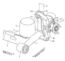
まず、構成について説明すると、図1及び図2に示すように、左右のトレーリングアーム1がそれぞれ車両前後方向に延び、その前端部がブッシュ2を介して車体に連結することで、トレーリングアーム1は上下方向に揺動可能となっている。左右のトレーリングアーム1間は、トーションビーム3で連結されている。図1中、符号4は補強板であって、サスペンションスプリング5の下端部が着座する。また、符号6はショックアブソーバを示す。
そして、各トレーリングアーム1の後部には、車輪Wを回転自在に支持するアクスル9が弾性支持されている。
トレーリングアーム1の後部にアクスルブラケット10が固定されている。そのブラケット10は、側面視で略三角形状をしていて、トレーリングアーム1に沿って車両前後方向に間隔を開けて配置される左右の取付け部10b、10cと、上方に延びその頂部に形成された上側の取付け部10aとを有する。各取付け部10a、10b、10cはそれぞれ、コ字状の部材からなり、車両前後方向で対向する一対の取付け板を備えてブッシュを取付け可能となっている。上記上側の取付け部の位置が上側連結点となり、その上側連結点よりも下側にある、左右の取付け部の位置が第1及び第2下側連結点となる。
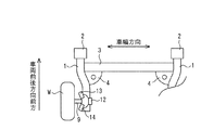
各腕部の先端部8a〜8cにはそれぞれ、ブッシュ12〜14が設けられている。各ブッシュ12〜14はそれぞれ、図3のように、同軸に配置された外筒16と内筒15との間に弾性体17が介装されて構成され、各外筒16が腕部先端部に一体的に固定されている。そして、各ブッシュ12〜14を各連結点に配置された取付け板間に配置すると共に、内筒15を貫通するボルトによって一対の取付け板に当該内筒15が締結されて取付けられている。
ここで、上側連結点のブッシュを第1ブッシュ12、下側連結点に位置する2つのブッシュを、第2ブッシュ13及び第3ブッシュ14と呼ぶ。
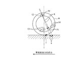
そして、本実施形態では、図4及び図5のように、上記第1ブッシュ12の位置、及び上記交差点P1の位置を調整して、仮想キングピン軸Kの地面との交点Aを、タイヤ接地点Tよりも車両前後方向後方且つ車幅方向外方となるように設定している。
図6に示すように、車両旋回によってタイヤに横力F1が作用すると、図7のように、仮想キングピン軸Kの接地点Aが、タイヤ接地点Tよりも後方にあることから、キングピン軸K周りのトルクによって車輪Wが転舵し、その転舵によって、旋回外輪側ではトーイン方向に微小回動し、旋回内輪ではトーアウト方向に微小回動する。
このとき、本実施形態では、各ブッシュ12〜14について、特に車軸の近くに配置されて横力F1を主として負担する第2及び第3ブッシュ13,14について、軸方向に対し軸直方向の剛性を大幅に高めているので、アクスル9を弾性支持する構成としても、キャンバ剛性を高く設定することができる。
また、前進走行時に制動が作用すると、図9のように、タイヤ接地点に前後力F2が作用するが、タイヤ接地点Tよりも仮想キングピン軸Kの接地点Aの方が車幅方向外方に位置することから、キングピン軸K周りの転舵によって車輪Wはトーイン方向の変化を生じて走行安定性が向上する。
しかも、弾性支持部材であるブッシュ12〜14と車軸との位置関係や、ブッシュ12〜14間の剛性の相対関係を固定する必要がないため設計自由度が増大し、容易に採用できる。
3 トーションビーム
9 アクスル
12〜14 ブッシュ
L1,L2 車幅方向への弾性主軸
P1 交差点
K キングピン軸
A キングピン軸の接地点
W 車輪
T タイヤ接地点
Claims (1)
- 車両前後方向に延び、前端部が車体に弾性支持される左右一対のトレーリングアームと、その左右のトレーリングアーム間に横架されるトーションビームと、を備え、左右の車輪を回転自在に支持するアクスルをそれぞれ、上記各トレーリングアームに、複数の連結点に配した弾性部材を介して弾性支持するサスペンション装置であって、
上記複数の連結点として、上側連結点と、その上側連結点よりも下方に位置し互いに車両前後方向に間隔を開けて配置される第1及び第2下側連結点とを有し、
上記第1及び第2下側連結点に配置される弾性部材は、入れ子状に配置された内筒及び外筒の間に弾性体が介装されてなるブッシュから構成され、平面視において、各ブッシュの軸を車両前後方向に向けると共に、各ブッシュの軸直方向に向かう弾性主軸同士が、平面視において、第1及び第2下側連結点よりも車幅方向外方で交差し、さらに、上記上側連結点は、側面視において、上記タイヤ接地点よりも車両前後方向前方に位置し、上記上側連結点と上記弾性主軸同士の交差点とを通過する直線の地面との交点は、平面視において、上記車輪内であってタイヤ接地点よりも車幅方向外方で且つ車両前後方向後方に位置し、
上記第1及び第2下側連結点に配置される各弾性部材は、上記内筒と外筒との間にある弾性体のうち、軸を挟んで車幅方向で対向する位置の少なくとも一方に、弾性体よりも剛性が高い中間板を介挿することにより、車両前後方向よりも車幅方向の剛性が高いことを特徴とするサスペンション装置。
Priority Applications (4)
| Application Number | Priority Date | Filing Date | Title |
|---|---|---|---|
| JP2005244494A JP4765484B2 (ja) | 2005-08-25 | 2005-08-25 | サスペンション装置 |
| US11/508,564 US7588261B2 (en) | 2005-08-25 | 2006-08-23 | Suspension device |
| CNB2006101118237A CN100475576C (zh) | 2005-08-25 | 2006-08-23 | 悬架装置 |
| EP06254460A EP1757468B1 (en) | 2005-08-25 | 2006-08-25 | Suspension device |
Applications Claiming Priority (1)
| Application Number | Priority Date | Filing Date | Title |
|---|---|---|---|
| JP2005244494A JP4765484B2 (ja) | 2005-08-25 | 2005-08-25 | サスペンション装置 |
Publications (2)
| Publication Number | Publication Date |
|---|---|
| JP2007055486A JP2007055486A (ja) | 2007-03-08 |
| JP4765484B2 true JP4765484B2 (ja) | 2011-09-07 |
Family
ID=37401425
Family Applications (1)
| Application Number | Title | Priority Date | Filing Date |
|---|---|---|---|
| JP2005244494A Expired - Fee Related JP4765484B2 (ja) | 2005-08-25 | 2005-08-25 | サスペンション装置 |
Country Status (4)
| Country | Link |
|---|---|
| US (1) | US7588261B2 (ja) |
| EP (1) | EP1757468B1 (ja) |
| JP (1) | JP4765484B2 (ja) |
| CN (1) | CN100475576C (ja) |
Families Citing this family (15)
| Publication number | Priority date | Publication date | Assignee | Title |
|---|---|---|---|---|
| US7556272B2 (en) * | 2005-09-06 | 2009-07-07 | Gm Global Technology Operations, Inc. | Twist axle suspensions |
| DE102007031165A1 (de) * | 2007-07-04 | 2009-01-08 | Schaeffler Kg | Verbundlenkerachse |
| DE102007043121A1 (de) * | 2007-09-10 | 2009-03-12 | GM Global Technology Operations, Inc., Detroit | Verbundlenkerachse mit elastisch aufgehängtem Radträger |
| MX2010012845A (es) * | 2008-05-23 | 2011-05-23 | Systeme Nenuphar Inc | Sistema de ajuste angular para suspension por torsion y suspension por torsion obtenida de esta forma. |
| DE102008031123A1 (de) * | 2008-07-02 | 2010-01-07 | Bayerische Motoren Werke Aktiengesellschaft | Gegenlenkende Fahrzeug-Hinterachse |
| WO2010034807A1 (en) | 2008-09-26 | 2010-04-01 | M.B. Gerrard V/Miles B. Gerrard | A vehicle suspension |
| DE102011013265A1 (de) * | 2011-03-07 | 2012-09-13 | Benteler Automobiltechnik Gmbh | Kraftfahrzeugachse mit virtueller Lenkachse |
| KR101461902B1 (ko) * | 2013-11-04 | 2014-11-14 | 현대자동차 주식회사 | 커플드 토션 빔 액슬 타입 현가장치 |
| FR3015416B1 (fr) * | 2013-12-20 | 2017-03-03 | Renault Sa | Train de suspension pour vehicule automobile, rotule de liaison pour le train et procede de montage correspondant |
| JP6369230B2 (ja) * | 2014-08-29 | 2018-08-08 | 日産自動車株式会社 | インホイール型サスペンション装置 |
| JP5879415B1 (ja) * | 2014-10-03 | 2016-03-08 | 株式会社エフテック | サスペンション部材用エンドプレート |
| DE102015110036B3 (de) * | 2015-06-23 | 2016-09-01 | Benteler Automobiltechnik Gmbh | Radaufhängung für eine Verbundlenkerachse |
| DE102019203836B4 (de) * | 2019-03-20 | 2025-03-06 | Audi Ag | Radaufhängung für eine Fahrzeugachse |
| WO2022191739A1 (ru) * | 2021-03-11 | 2022-09-15 | Общество С Ограниченной Ответственностью "Научно-Производственное Объединение Имени Петрова В.А." | Независимая рычажная подвеска транспортного средства с мотор-колесом |
| JP7705610B2 (ja) * | 2022-02-15 | 2025-07-10 | スズキ株式会社 | 車両用リアサスペンション構造 |
Family Cites Families (20)
| Publication number | Priority date | Publication date | Assignee | Title |
|---|---|---|---|---|
| DE2311480C3 (de) * | 1973-03-08 | 1980-07-03 | Dr.Ing.H.C. F. Porsche Ag, 7000 Stuttgart | Radaufhängung für nicht gelenkte Hinterräder von Kraftfahrzeugen |
| JPS5914504B2 (ja) | 1978-01-17 | 1984-04-04 | 日瀝化学工業株式会社 | 舗装用瀝青組成物 |
| JPS5897508A (ja) * | 1981-12-07 | 1983-06-10 | Nissan Motor Co Ltd | 円筒形ゴムブツシユ |
| US4526400A (en) | 1982-04-28 | 1985-07-02 | Mazda Motor Corporation | Vehicle rear suspension mechanism |
| JPS5914510A (ja) * | 1982-07-16 | 1984-01-25 | Mazda Motor Corp | 自動車のリヤサスペンシヨン |
| DE3480186D1 (en) * | 1983-09-02 | 1989-11-23 | Mazda Motor | Vehicle rear suspension system |
| JPH0399914A (ja) * | 1989-09-14 | 1991-04-25 | Mazda Motor Corp | 車両のサスペンション装置 |
| JPH04287708A (ja) * | 1991-03-18 | 1992-10-13 | Daihatsu Motor Co Ltd | 自動車のリヤサスペンション |
| JPH04112103U (ja) * | 1991-03-18 | 1992-09-29 | ダイハツ工業株式会社 | 自動車のリヤサスペンシヨン |
| JP3669642B2 (ja) | 1995-01-17 | 2005-07-13 | 本田技研工業株式会社 | 車両用懸架装置 |
| JP2000025438A (ja) * | 1998-07-14 | 2000-01-25 | Nissan Motor Co Ltd | 車両用サスペンション装置 |
| JP4366822B2 (ja) * | 2000-03-24 | 2009-11-18 | 日産自動車株式会社 | トレーリングアーム式リアサスペンション |
| JP2002012015A (ja) | 2000-04-27 | 2002-01-15 | Nissan Motor Co Ltd | サスペンション装置 |
| US7128327B2 (en) | 2001-06-21 | 2006-10-31 | Bridgestone Corporation | Axle with rubber cushion |
| JP4592226B2 (ja) * | 2001-07-11 | 2010-12-01 | 富士重工業株式会社 | 独立懸架式サスペンション |
| JP2004224064A (ja) | 2003-01-20 | 2004-08-12 | Nissan Motor Co Ltd | リアサスペンション |
| DE10321877B4 (de) * | 2003-05-15 | 2005-04-28 | Daimler Chrysler Ag | Radträgerlagerung mit Pendelplatte |
| JP2005119601A (ja) | 2003-10-20 | 2005-05-12 | Honda Motor Co Ltd | トーションビーム式サスペンション |
| JP2005225382A (ja) * | 2004-02-13 | 2005-08-25 | Honda Motor Co Ltd | 車両用リヤサスペンション装置 |
| US7431315B2 (en) * | 2005-07-11 | 2008-10-07 | Ford Global Technologies, Llc | Vehicle suspension system with wheel support knuckle and trailing arm attached to toe link |
-
2005
- 2005-08-25 JP JP2005244494A patent/JP4765484B2/ja not_active Expired - Fee Related
-
2006
- 2006-08-23 US US11/508,564 patent/US7588261B2/en not_active Expired - Fee Related
- 2006-08-23 CN CNB2006101118237A patent/CN100475576C/zh not_active Expired - Fee Related
- 2006-08-25 EP EP06254460A patent/EP1757468B1/en not_active Not-in-force
Also Published As
| Publication number | Publication date |
|---|---|
| US7588261B2 (en) | 2009-09-15 |
| US20070052192A1 (en) | 2007-03-08 |
| EP1757468B1 (en) | 2011-10-19 |
| CN1919628A (zh) | 2007-02-28 |
| JP2007055486A (ja) | 2007-03-08 |
| EP1757468A1 (en) | 2007-02-28 |
| CN100475576C (zh) | 2009-04-08 |
Similar Documents
| Publication | Publication Date | Title |
|---|---|---|
| JP4305429B2 (ja) | インホイールサスペンション | |
| JP3550908B2 (ja) | フロントサスペンション装置 | |
| JP4765484B2 (ja) | サスペンション装置 | |
| WO2010122837A1 (ja) | サスペンション装置 | |
| JP2008018924A (ja) | サスペンション装置 | |
| KR101461915B1 (ko) | 커플드 토션 빔 액슬 타입 현가장치 | |
| JP2008254568A (ja) | 後輪用サスペンション装置 | |
| WO2014129046A1 (ja) | サスペンションアームの構造及びサスペンション装置 | |
| JPH111110A (ja) | フロントサスペンション装置 | |
| JP4389774B2 (ja) | 車軸懸架装置 | |
| JP2010126014A (ja) | フロント・サスペンション装置 | |
| JP4370518B2 (ja) | 自動車のフロントサスペンション装置 | |
| JP2006347337A (ja) | 自動車のリヤサスペンション装置 | |
| JP4664796B2 (ja) | 操舵輪用サスペンション装置 | |
| JP5056235B2 (ja) | 車両用副操舵輪のサスペンション装置 | |
| JP5145892B2 (ja) | リヤサスペンション装置 | |
| JP3170032B2 (ja) | 自動車のフロントサスペンション | |
| JP2022114514A (ja) | 車両懸架システム | |
| JP3767078B2 (ja) | 操舵輪用サスペンション装置 | |
| JP4534136B2 (ja) | 自動車のフロントサスペンション装置 | |
| JP5267168B2 (ja) | サスペンション装置 | |
| JP2006335118A (ja) | サスペンション装置 | |
| JP2024098331A (ja) | 車両用リアサスペンション構造 | |
| JP2000043529A (ja) | フロントサスペンション装置 | |
| JP2008254543A (ja) | サスペンション装置 |
Legal Events
| Date | Code | Title | Description |
|---|---|---|---|
| A621 | Written request for application examination |
Free format text: JAPANESE INTERMEDIATE CODE: A621 Effective date: 20080625 |
|
| A977 | Report on retrieval |
Free format text: JAPANESE INTERMEDIATE CODE: A971007 Effective date: 20100826 |
|
| A131 | Notification of reasons for refusal |
Free format text: JAPANESE INTERMEDIATE CODE: A131 Effective date: 20100831 |
|
| RD04 | Notification of resignation of power of attorney |
Free format text: JAPANESE INTERMEDIATE CODE: A7424 Effective date: 20100917 |
|
| A521 | Written amendment |
Free format text: JAPANESE INTERMEDIATE CODE: A523 Effective date: 20101027 |
|
| A02 | Decision of refusal |
Free format text: JAPANESE INTERMEDIATE CODE: A02 Effective date: 20110125 |
|
| A521 | Written amendment |
Free format text: JAPANESE INTERMEDIATE CODE: A523 Effective date: 20110405 |
|
| A911 | Transfer to examiner for re-examination before appeal (zenchi) |
Free format text: JAPANESE INTERMEDIATE CODE: A911 Effective date: 20110413 |
|
| A01 | Written decision to grant a patent or to grant a registration (utility model) |
Free format text: JAPANESE INTERMEDIATE CODE: A01 Effective date: 20110517 |
|
| A61 | First payment of annual fees (during grant procedure) |
Free format text: JAPANESE INTERMEDIATE CODE: A61 Effective date: 20110530 |
|
| R150 | Certificate of patent or registration of utility model |
Free format text: JAPANESE INTERMEDIATE CODE: R150 |
|
| FPAY | Renewal fee payment (event date is renewal date of database) |
Free format text: PAYMENT UNTIL: 20140624 Year of fee payment: 3 |
|
| LAPS | Cancellation because of no payment of annual fees |