WO2014065196A1 - 混注装置 - Google Patents
混注装置 Download PDFInfo
- Publication number
- WO2014065196A1 WO2014065196A1 PCT/JP2013/078228 JP2013078228W WO2014065196A1 WO 2014065196 A1 WO2014065196 A1 WO 2014065196A1 JP 2013078228 W JP2013078228 W JP 2013078228W WO 2014065196 A1 WO2014065196 A1 WO 2014065196A1
- Authority
- WO
- WIPO (PCT)
- Prior art keywords
- syringe
- mixed injection
- needle
- infusion
- processing chamber
- Prior art date
- Legal status (The legal status is an assumption and is not a legal conclusion. Google has not performed a legal analysis and makes no representation as to the accuracy of the status listed.)
- Ceased
Links
Images










Classifications
-
- A—HUMAN NECESSITIES
- A61—MEDICAL OR VETERINARY SCIENCE; HYGIENE
- A61J—CONTAINERS SPECIALLY ADAPTED FOR MEDICAL OR PHARMACEUTICAL PURPOSES; DEVICES OR METHODS SPECIALLY ADAPTED FOR BRINGING PHARMACEUTICAL PRODUCTS INTO PARTICULAR PHYSICAL OR ADMINISTERING FORMS; DEVICES FOR ADMINISTERING FOOD OR MEDICINES ORALLY; BABY COMFORTERS; DEVICES FOR RECEIVING SPITTLE
- A61J1/00—Containers specially adapted for medical or pharmaceutical purposes
- A61J1/14—Details; Accessories therefor
- A61J1/20—Arrangements for transferring or mixing fluids, e.g. from vial to syringe
- A61J1/2096—Combination of a vial and a syringe for transferring or mixing their contents
-
- A—HUMAN NECESSITIES
- A61—MEDICAL OR VETERINARY SCIENCE; HYGIENE
- A61J—CONTAINERS SPECIALLY ADAPTED FOR MEDICAL OR PHARMACEUTICAL PURPOSES; DEVICES OR METHODS SPECIALLY ADAPTED FOR BRINGING PHARMACEUTICAL PRODUCTS INTO PARTICULAR PHYSICAL OR ADMINISTERING FORMS; DEVICES FOR ADMINISTERING FOOD OR MEDICINES ORALLY; BABY COMFORTERS; DEVICES FOR RECEIVING SPITTLE
- A61J1/00—Containers specially adapted for medical or pharmaceutical purposes
- A61J1/14—Details; Accessories therefor
- A61J1/20—Arrangements for transferring or mixing fluids, e.g. from vial to syringe
-
- B—PERFORMING OPERATIONS; TRANSPORTING
- B25—HAND TOOLS; PORTABLE POWER-DRIVEN TOOLS; MANIPULATORS
- B25J—MANIPULATORS; CHAMBERS PROVIDED WITH MANIPULATION DEVICES
- B25J21/00—Chambers provided with manipulation devices
-
- B—PERFORMING OPERATIONS; TRANSPORTING
- B25—HAND TOOLS; PORTABLE POWER-DRIVEN TOOLS; MANIPULATORS
- B25J—MANIPULATORS; CHAMBERS PROVIDED WITH MANIPULATION DEVICES
- B25J9/00—Program-controlled manipulators
- B25J9/0084—Program-controlled manipulators comprising a plurality of manipulators
-
- A—HUMAN NECESSITIES
- A61—MEDICAL OR VETERINARY SCIENCE; HYGIENE
- A61J—CONTAINERS SPECIALLY ADAPTED FOR MEDICAL OR PHARMACEUTICAL PURPOSES; DEVICES OR METHODS SPECIALLY ADAPTED FOR BRINGING PHARMACEUTICAL PRODUCTS INTO PARTICULAR PHYSICAL OR ADMINISTERING FORMS; DEVICES FOR ADMINISTERING FOOD OR MEDICINES ORALLY; BABY COMFORTERS; DEVICES FOR RECEIVING SPITTLE
- A61J3/00—Devices or methods specially adapted for bringing pharmaceutical products into particular physical or administering forms
- A61J3/002—Compounding apparatus specially for enteral or parenteral nutritive solutions
Definitions
- This invention relates to a co-infusion apparatus for mixing and adjusting a drug such as an anticancer drug in an infusion solution (replacement fluid).
- mixed injection processing that mixes and adjusts such drugs in infusions is performed in a safety cabinet set to negative pressure. .
- the drug compounder sucks the infusion solution from the infusion bag with a syringe, and inserts the injection needle of the syringe into the cap portion ( The infusion solution in the syringe is poured into a vial through a rubber stopper. Then, the drug compounder sucks the infusion solution in which the drug is dissolved into the syringe.
- the drug compounder Since a certain amount of the drug is sealed in the vial, the drug compounder repeatedly performs the operation of injecting and sucking the infusion into a plurality of vials until the required amount of the drug is dissolved in the infusion.
- the drug compounder dissolves a necessary amount of drug in the infusion solution, and then inserts the injection needle of the syringe into the mixed injection port of the infusion bag to return the infusion solution in which the drug in the syringe is dissolved into the infusion bag.
- Patent Document 1 discloses a radiopharmaceutical dispensing apparatus that dispenses while avoiding the danger of exposure to a radiopharmaceutical. Further, in Patent Document 2, in medicines and medicine containers with different handling techniques, the posture of the medicine container is differentiated as a posture suitable for each container so that it can be handled in the same manner by one apparatus. A drug mixing device is disclosed.
- Patent Document 1 is not used as a co-infusion apparatus for injecting a liquid medicine into an infusion bag, and does not show any technique for preventing exposure to the medicine.
- the apparatus of the said patent document 2 can inject
- the present invention provides a co-infusion apparatus that can appropriately and automatically process part or all of co-infusion processing.
- a co-infusion apparatus of the present invention includes a first robot arm that holds a drug container, a second robot arm that holds a syringe and performs suction and injection of liquid medicine by the syringe, and at least The co-infusion processing chamber in which co-infusion processing is performed by the two robot arms, and at least the two robot arms are operated so that the liquid medicine in the medicine container or the liquid medicine generated in the medicine container is obtained by the syringe. And a control unit that executes a process of sucking and injecting the liquid medicine into the infusion bag by the syringe.
- At least said 2 robot arm will be operated, the liquid medicine in the said medicine container or the liquid medicine produced
- the infusion bag may be located outside the mixed injection processing chamber. According to this, it is possible to prevent the infusion bag from being exposed to the medicine.
- the waste storage chamber located below the mixed injection processing chamber, the sealed door for closing the garbage storage chamber, the communication portion for connecting the mixed injection processing chamber and the garbage storage chamber, and the mixed injection processing chamber
- a hermetic dust lid provided on an upper portion of the dust communication portion.
- An exhaust path for making the above-described garbage storage chamber into a negative pressure may be provided. There may be provided an exhaust path for making the dust communication part negative pressure.
- the garbage communication part may be provided with a connection part to which a mouth of the garbage bag is connected. Any of the plurality of robot arms may be provided at a position where dust can be put into the dust communication portion.
- the second robot arm is provided with a holding portion for holding the syringe by moving a pair of claw portions close to and away from each other, and above the opposing surfaces of the claw portions facing each other, from the upper end surface of the claw An inclined portion that is inclined downward toward the facing surface may be formed. According to this, when throwing away the nail
- the second robot arm is provided with a plunger operating portion that holds the plunger of the syringe by moving the pair of claws close to and away from each other and moves the plunger, and holds the plunger operating portion or the syringe.
- the holding unit may also include a gripping claw for gripping the article.
- a needle bend detection unit for detecting the bend of the injection needle attached to the syringe may be provided.
- the bending detection unit uses position information when the injection needle of the syringe held and moved by the second robot arm blocks the light beam of the optical sensor having the light emitting unit and the light receiving unit. A bend may be detected.
- a syringe take-out door in which the front door portion and the back door portion are positioned in an L shape is provided to open and close an opening leading to the mixed injection processing chamber by rotating about the vertical axis.
- the extraction door is configured such that a syringe stand provided on the back surface of the front door portion or the surface of the back door portion is positioned outside the mixed injection processing chamber, and the opening is closed by the back door portion. May be.
- An injection needle attaching / detaching device that holds and attaches a horizontal or upward injection needle may be provided.
- the injection needle and the cap are After correcting the relative position and inserting the injection needle partway into the cap, the center of the base of the injection needle and the center of the inlet of the cap may be made to coincide with each other.
- the first robot arm has a pair of concave gripping portions that come into contact with each other when holding the drug container, and one concave gripping portion may be movably provided. According to this, it is possible to solve the problem that the medicine container is not properly held due to the stagnation of the medicine container and the thickness of the label.
- a member is detachably provided, and at least one robot arm may execute an operation of grasping the member in order to confirm the presence or absence of the member. According to this, when the said member is grasped
- a needle tip detection unit for detecting the tip position of the injection needle attached to the syringe may be provided. According to this, the exact distance from the holding position of the syringe of the second robot arm to the tip of the injection needle can be determined.
- the second robot arm may perform a pulling operation necessary for sucking in a larger amount of liquid than that prescribed in the prescription content information when sucking infusion or liquid medicine into the syringe. Good. According to this, even when the tip rubber of the plunger of the syringe moves, after the pulling operation is performed, the plunger is returned to a position where the prescribed liquid amount is obtained, whereby the prescribed liquid amount is obtained. Can be reliably taken into the syringe body.
- the accuracy of the weighing instrument that measures the weight of the syringe may be made rougher as the amount of liquid sucked into the syringe is larger.
- the higher the accuracy of the weighing meter the longer the time required for measurement.
- the greater the amount of liquid sucked into the syringe the lower the required accuracy. Therefore, it is possible to avoid an increase in measurement time when the accuracy of the weighing meter is fixed regardless of the amount of liquid.
- the operation of pushing the plunger of the syringe into the syringe body in the mixed injection processing chamber may be performed before the operation of sucking infusion or liquid medicine with the syringe placed in the mixed injection processing chamber. According to this, in the syringe placed in the mixed injection processing chamber, it is possible to eliminate the gap existing between the tip of the plunger and the tip in the syringe body.
- an operation of pushing the plunger into the syringe body may be performed using a plunger operation unit that operates the plunger. According to this, the operation time can be shortened by making use of the operation of holding the syringe inherently performed by the second robot arm.
- the medicine tray on which the syringe and the medicine container are placed may be moved so as to face the mixed injection processing chamber.
- this is employed, the following configuration can be adopted.
- the adjustment container provided so that the infusion bag holding portion for holding the medicine tray and the infusion bag can be removed may be set at a set position outside the mixed injection processing chamber.
- the process of moving the medicine tray from the adjustment container set at the set position outside the mixed injection processing chamber into the mixed injection processing chamber, and the adjustment container from the adjustment container while leaving the medicine tray in the mixed injection processing chamber A process of passing the infusion bag holding part to a holding operation part for holding the infusion bag for needle stick, a process of returning the adjustment container without the infusion bag holding part to the set position, and a return to the set position.
- a process of returning the medicine tray to the adjustment container may be performed.
- medical agent container in which the powder medicine is put with a syringe the process which takes out the said syringe and a chemical
- the infusion bag holding unit can already be handed over to the holding operation unit. Therefore, the infusion bag is set with the syringe set on the robot arm. The process of sucking the infusion solution from can be performed quickly. Further, the emptied medicine tray can be returned to the adjustment container returned to the set position.
- the drug tray may be moved downward when a predetermined load or more is received from above while facing the mixed injection processing chamber. According to this, for example, even if the robot arm fails to grip the medicine container on the medicine tray and the medicine tray is pushed downward, the medicine tray moves downward. Therefore, it is possible to prevent the medicine container and the medicine tray from being damaged.
- the drug tray may automatically rise when the load is removed and return to the position facing the mixed injection processing chamber.
- a sensor for detecting the inclination of the medicine tray facing the mixed injection processing chamber may be provided.
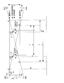
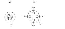
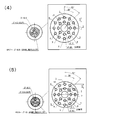
- FIG. 6A is a perspective view showing the chuck portion of the infusion bag holding portion of FIG. 6, and FIG. 4B is an explanatory view showing the positional relationship between the mark and the mixed injection port.
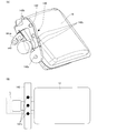
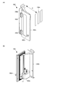
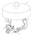
- FIGS. 4A and 4B are explanatory views showing a syringe outlet door of the co-infusion apparatus of FIG. It is the perspective view which showed the robot arm comprised so that turning was possible.
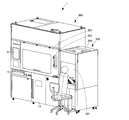
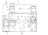
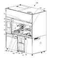
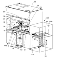
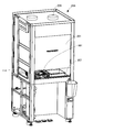
- the co-infusion apparatus 1 includes a supply unit 200 and a main body unit 300.
- the supply unit 200 is provided with a door 201, a work table 202, and the like. On the work table 202, a display 203, a barcode reader 204, and the like are arranged.
- the supply unit 200 is a clean bench having an air cleaning device 206 and the like.
- the syringe 11, the medicine container 10, the infusion bag 12, and the like are set by, for example, human work for each patient or each application.
- the supply unit 200 and the main body 300 are communicated with each other through a communication opening 114, and the adjustment container 101 can be put into the main body 300 through the communication opening 114.
- the supply unit 200 may automatically carry the adjustment container 101 into the main body 300.
- a main door 301, a syringe take-out door 302, a garbage storage room door 13, a touch panel monitor 14, an adjustment container take-out door 15 and the like are provided on the front side outer wall of the main body 300.
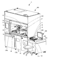
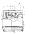
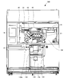
- an ampoule cutter 31 As shown in FIGS. 2 and 3, an ampoule cutter 31, a stirring device 32, a temporary storage shelf 33, a drug barcode reader 34, a weighing meter 35, a needle bending detection unit 36, and a mixed injection A communication port 37, a needle insertion confirmation transparent window 38, a dust lid 132a, and the like are provided.
- a tray confirmation camera 41, a syringe confirmation camera 42, a syringe needle attachment / detachment device 43, a needle insertion confirmation camera 44, a sterilization lamp 45, and the like are provided on the ceiling side of the mixed injection processing chamber 104. ing.
- a first robot arm 21 and a second robot arm 22 having a multi-joint structure are provided in a hanging shape with their base ends fixed to the ceiling side.
- the first robot arm 21 is disposed closer to the supply unit 200 than the second robot arm 22, and the second robot arm 22 is connected to the mixed injection communication port compared to the first robot arm 21. It is arranged at a position close to 37.
- a dome-shaped light that illuminates the infusion bag 12 transported to the container transport terminal portion 110a is located above the container transport terminal portion 110a located in the left space of the mixed injection processing chamber 104. 120 is provided.
- a camera 121 for reading a barcode attached to the surface of the infusion bag 12 is provided at the center of the dome-shaped light 120. Since the shape of the surface of the infusion bag 12 is not uniform, an error is likely to occur when reading with a normal laser, but a bar code is displayed by an image captured by the camera 121 so that a shadow is not easily generated with the dome-shaped light 120. When read, errors can be made less likely to occur. Note that where the barcode exists in the infusion bag 12 can be determined by comparing the information on the infusion bag specified in the prescription content information with the data in the master table (drug etc. database). .
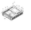
- the medicine tray 102 (see FIGS. 8 and 10) on which the medicine container 10 and the syringe 11 are placed, and the infusion bag 12 are held.
- the infusion bag holding unit 103 is separated and provided movably.
- the drug container 10 is an ampoule
- the ampoule is set in a state where the ampoule is stood diagonally at a specified position without being laid down on the drug tray 102.
- an injection needle is also placed at a designated position.
- the vial and the syringe 11 are loosened.
- such an arrangement is merely an example, and the present invention is not limited to this.
- each adjustment container 101 is provided with an IC tag (for example, RFID: Radio Frequency Identification) for the controller 500 (see FIG. 9) of the co-infusion apparatus 1 to recognize various types of information.
- the controller 500 reads the information of the IC tag by a reading unit (not shown) and recognizes the contents of the mixed injection process to be started.
- the controller 500 specifies patient information, doctor information, mixed injection operation program, prescription content information (the type and number of drugs, syringes, injection needles used for mixed injection processing) specified by the read IC tag information.
- the mixed injection operation program may differ depending on the type of the drug container 10 (for example, which of the vials containing powdered drugs or the ampule is used), and the number of repetitions of the predetermined operation depending on the number of drug containers 10 to be used. Will be decided.
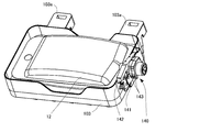
- the infusion bag holding portion 103 is provided with a chuck portion 140 for fixing the mixed injection port (neck portion) of the infusion bag 12.
- the chuck portion 140 includes a lower member 141 and an upper member 142 as shown in FIGS. 6, 7 ⁇ / b> A, and 7 ⁇ / b> B.
- the lower member 141 is formed with a gear portion 141a
- the upper member 142 is provided with a ratchet portion that meshes with the gear portion 141a.
- a plurality of (for example, three) marks 142c are formed in a straight line on the upper surface of the upper member 142, for example.
- the mixed injection port of the infusion bag 12 is placed in a region L having a width between the marks 142c located at the end when locked.
- the infusion bag holding portion 103 is provided with two engaging portions 103 a that protrude from the edge of the adjustment container 101.
- the lateral displacement amount of the mark 142c with respect to the mixed injection port (neck portion) increases as the opening angle of the upper member 142 with respect to the lower member 141 increases.
- the mark 142c can also be imaged.
- the controller 500 executes a process for recognizing the mixed injection port and the mark 142c in the captured image. If the mark 142c cannot be detected, the mixed injection port of the infusion bag 12 exists in the region L. If there is no, or if the center line of the co-injection port does not pass over the center mark 142c, it is determined that a lock failure has occurred and error processing is performed. In addition, when the mixed injection port (neck part) is simply on the upper member 142, the mark 142c may be hidden by the mixed injection port and the mark 142c cannot be detected.
- the adjustment container 101 can be moved to the container transport unit 110 of the main body 300 using the communication opening 114.
- the inside of the container transfer unit 110 is set to a positive pressure than the inside of the mixed injection processing chamber 104.
- the container transport unit 110 is provided so as to transport the adjustment container 101 to the rear side of the dust storage chamber 13a located below the mixed injection processing chamber 104 and below the dust cover 132a. Thereby, the said garbage storage chamber 13a can be accessed from the front side of a mixed injection apparatus.
- the adjustment container 101 that moves in the container transfer unit 110 is indicated by a two-dot chain line in order to show the transfer route of the container transfer unit 110.
- a plurality of the adjustment containers 101 does not exist in the container transport unit 110 at the same time.
- the adjustment container 101 may be configured so that the adjustment container 101 can pass through the lower side of the infusion bag ascending / descending inclined portion 113 while the adjustment container 101 is conveyed to the left side wall on the back side of the main body 300.
- the container transfer unit 110 moves the adjustment container 101 from a position closer to the first robot arm 21 than the second robot arm 22 to a position closer to the second robot arm 22 than the first robot arm 21.
- Transport When the adjustment container 101 is close to the first robot arm 21, the drug container 10, the syringe 11, and the like are picked up by the first robot arm 21 and the temporary storage shelf 33 of the mixed injection processing chamber 104. Temporarily placed. Further, when the adjustment container 101 is transported to a position close to the second robot arm 22, the mixed injection port of the infusion bag 12 held by the infusion bag holding portion 103 of the adjustment container 101 is used for the mixed injection processing. An operation of positioning the co-injection communication port 37 formed in the chamber 104 is performed. Details thereof will be described later.
- the first and second robot arms 21 and 22 are controlled by a controller (computer) 500.
- the controller 500 determines that the adjustment container 101 has reached a predetermined position in the container transport unit 110 through the communication opening 114 based on, for example, the output of a sensor, the controller 500
- the shutter 111 that opens and closes the tray opening 104a that communicates with the mixed injection processing chamber 104 is slid in the horizontal direction.
- the medicine tray 102 appears in the mixed injection processing chamber 104 from the tray opening 104a.
- FIG. 8 shows a state where the medicine tray 102 appears in the mixed injection processing chamber 104.
- the tray confirmation camera 41 images the syringe 11 and the like on the medicine tray 102.
- the controller 500 executes image recognition processing using the image captured by the tray confirmation camera 41, and whether or not the number of syringes 11 and drug containers 10 specified in the prescription content are present on the drug tray 102. Etc.
- the container transport unit 110 includes a tray lifting unit that lifts and lowers the drug tray 102 in the adjustment container 101 moved into the container transport unit 110 through the communication opening 114. 112 is provided.
- the tray lifting / lowering unit 112 lifts the drug tray 102 from below by, for example, four shafts 112a provided so as to be able to lift and lower.
- a through-hole through which the four shafts 112a pass is formed on the lower surface of the adjustment container 101.
- the controller 500 raises the medicine tray 102 by the tray lifting / lowering unit 112 and then performs imaging by the tray confirmation camera 41 as described above.
- the controller 500 controls the first robot arm 21 and the second robot arm 22, and grasps the syringe 11 and the like on the medicine tray 102 appearing in the mixed injection processing chamber 104 with the first robot arm 21.
- An operation of giving the syringe 11 to the second robot arm 22 and an operation of temporarily placing the syringe 11 on the temporary storage shelf 33 in the mixed injection processing chamber 104 are executed.
- the controller 500 grasps the positions and orientations of the vials and the syringes placed in bulk by image recognition processing on the captured image of the tray confirmation camera 41, and controls the first robot arm 21. Further, the controller 500 determines whether or not all articles on the medicine tray 102 have been taken out by the image recognition process.
- the controller 500 includes the medicine, the syringe, and the injection needle in the medicine tray 102 corresponding to the number of medicines, the syringes, and the needles indicated in the prescription content information. It may be determined based on an image captured by the tray check camera 41. If it does not exist, that fact may be displayed on the touch panel monitor 14. Further, when the shutter 111 is opened before the syringe 11 and the like in the medicine tray 102 are taken out by the first robot arm 21, the medicine tray 102 is photographed by the tray confirmation camera 41, and such a determination is made. It is possible to notify the shortage of drugs, syringes, and needles at an early stage.
- the controller 500 operates to lower the shaft 112a of the tray lifting / lowering unit 112 after closing all the drug containers 10 and the like from the drug tray 102 into the mixed injection processing chamber 104, to close the shutter 111, An operation of transporting the adjustment container 101 to a position close to the second robot arm 22 is performed.
- the first robot arm 21 grasps the drug container 10 on the drug tray 102 and puts it into the mixed injection processing chamber 104, so that the drug tray 102 has the adjustment container 101.
- the medicine tray 102 can be used repeatedly.
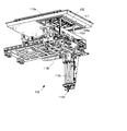
- an infusion bag ascending / descending inclined portion (holding operation portion) 113 is provided in the container transfer terminal portion 110a located in the container transfer portion 110 and close to the second robot arm 22. It has been.
- FIG. 10 shows the infusion bag up-and-down inclination part 113 in the lowered state and the infusion bag up-and-down inclination part 113 in the up state.
- the controller 500 transports the adjustment container 101 to the front of the infusion bag ascending / descending slope 113, and then hooks the hook portion 113a of the infusion bag ascending / descending slope 113 from below into the engagement hole 103a.
- the bag holding part 103 is raised, and the mixed injection port of the infusion bag 12 is positioned at the mixed injection communication port 37.
- the mixed injection communication port 37 is formed in a dome-like portion protruding outward on the side wall of the mixed injection processing chamber 104, and a notch for passing the mixed injection port in the vertical direction is formed in the dome-like portion. Therefore, the mixed injection port of the infusion bag 12 is positioned in the mixed injection processing chamber 104 by raising the infusion bag holding portion 103.
- a shutter is provided at the mixed injection communication port 37, an operation of opening the shutter is performed.
- the infusion bag ascending / descending inclined portion 113 is formed with a fan-shaped arc gear portion 113b which is rotatably provided, and a gear driven by a motor 113c meshes with the arc gear portion 113b. .
- the infusion bag up-and-down inclination portion 113 can incline the infusion bag holding portion 103 to make the mixed injection port of the infusion bag 12 upward or downward.
- the controller 500 controls the infusion bag ascending / descending inclined portion 113 so that the mixed injection port is directed obliquely upward.
- the controller 500 controls the infusion bag ascending / descending inclined portion 113 so that the mixed injection port is directed obliquely downward when the injection needle is inserted from the mixed injection port of the infusion bag 12 and the liquid medicine is injected into the infusion bag 12. To do.
- the mixed injection port is directed obliquely downward in this way, foaming during injection can be prevented and mixing can be promoted.
- the mixed injection communication port 37 is provided on the bottom surface of the mixed injection processing chamber 104, the liquid medicine scattered from the injection needle 11c or the like is likely to stick to the mixed injection processing chamber 104. Further, when the mixed injection port of the infusion bag 12 is directed upward, the liquid layer is lowered, and the liquid level is different for each infusion bag. Therefore, in order to put the injection needle into the liquid layer in the large infusion bag, a long injection needle 11c is used. The need to use is generated. On the other hand, since the mixed injection communication port 37 is provided on the side wall of the mixed injection processing chamber 104, the above problem does not occur. The mixed injection communication port 37 may be provided not on the side wall on the side of the mixed injection processing chamber 104 but on the back side wall.
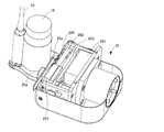
- the first robot arm 21 includes a container holding unit 25 that holds the drug container 10.
- the second robot arm 22 includes a syringe operation unit 26 that holds the syringe 11 and performs suction and injection of the liquid medicine by the syringe 11.
- the container holding portion 25 is screwed into a pair of gripping claws 25 a, a motor 251, two screw shafts 252 and 253 rotated by the motor 251, and the screw shafts 252 and 253.
- Nut blocks 254 and 255 are provided.
- the pair of gripping claws 25a are fixed to the nut blocks 254 and 255, respectively.
- the nut blocks 254 and 255 are moved by the rotation of the screw shafts 252 and 253, and the pair of gripping claws 25a are moved close to and away from each other to hold the container holding portion 25.
- the pair of gripping claws 25a have a recess suitable for holding a vial and a recess suitable for holding an ampoule on the tip side.
- FIG. 11 shows a state where both the vial and the ampoule are held, but actually, one drug container 10 is held.
- the container holding unit 25 uses the pair of gripping claws 25a when the first robot arm 21 temporarily places the medicine container 10 and the syringe 11 on the temporary placement shelf 33 of the mixed injection processing chamber 104.
- the injection needle with a cap and the syringe 11 can also be held.
- the container holding part 25 can measure the diameter of the syringe 11 when the syringe 11 is held by the pair of gripping claws 25a.
- the controller 500 can determine whether or not it is the designated syringe 11 from the measured value and the prescription content information.
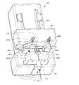
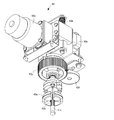
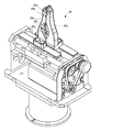
- the syringe operation unit 26 includes a syringe holding unit 261, a plunger holding unit 262, and a moving unit 263.
- the syringe holder 261 includes a pair of gripping claws 261 a that hold the syringe body 11 a of the syringe 11.
- the pair of gripping claws 261 a are held close to and away from each other and hold the syringe body 11 a of the syringe 11 by a mechanism similar to the drive mechanism used in the container holding unit 25.
- inclined portions 261b that are inclined downward from the gripping claw upper end surface toward the facing surface are formed on opposing surfaces facing each other.
- the plunger holding portion 262 includes a pair of gripping claws 262a that hold the buttocks of the plunger 11b of the syringe 11.
- the pair of gripping claws 262a are held close to and away from each other by a mechanism similar to the drive mechanism used in the container holding unit 25 to hold the collar portion of the plunger 11b of the syringe 11.
- a second gripping claw 262b is fixed to the upper surface of each gripping claw 262a. Accordingly, by moving the pair of gripping claws 262a closer to and away from each other, the pair of second gripping claws 262b can also be moved closer to and away from each other, and other articles such as drugs can be gripped.
- the recessed part for the collar part of the said plunger to enter is formed in the upper surface of the opposing side of said pair of holding claws 262a. Further, the tips of the pair of second gripping claws 262b protrude forward from the pair of gripping claws 262a, so that it is easy to grip an article.
- the second grip claw 262b may be provided on the grip claw 261a.
- the moving part 263 moves the plunger holding part 262 in the moving direction of the plunger 11b of the syringe 11.
- This movement includes, for example, a motor, a screw shaft rotated by the motor, a nut block screwed to the screw shaft, a guide, and the like.
- the plunger holding portion 262 is fixed to the nut block, and moves as the nut block moves.
- the second robot arm 22 inserts the injection needle 11c of the syringe 11 into the mouth portion of the drug container 10 held by the container holding portion 25 of the first robot arm 21 and the above. An operation of inserting the injection needle 11c of the syringe 11 into the mixed injection port of the infusion bag 12 is executed.
- the first robot arm 21 can stand the medicine container 10 held by the container holding part 25 and point the above-described mouth part upward.
- the second robot arm 22 can stand the syringe 11 held by the syringe operation unit 26 and point the syringe needle 11c downward.
- the drug container 10 and the syringe 11 are brought close to each other, and the injection needle 11 c of the syringe 11 is inserted into the mouth of the drug container 10.
- the drug container 10 is a vial with a rubber cap
- the injection needle 11c is inserted straight into the rubber cap.
- the first robot arm 21 and the second robot arm 22 make the posture of the drug container 10 and the syringe 11 oblique when sucking the liquid medicine in the drug container 10 into the syringe 11.
- an ampoule is used as the drug container 10
- a certain amount of liquid medicine is sucked from the drug container 10
- the drug container 10 is inclined by about 100 degrees with respect to the vertical direction so that the mouth side ( By forming a state in which the liquid medicine is moved to the neck portion, it is possible to suck up the liquid medicine without leaving the tip of the injection needle 11c of the syringe 11 to the bottom of the medicine container 10 as much as possible.
- the liquid medicine in the syringe 11 hangs down on the inner wall of the vial 11 by tilting the position of the vial that is the medicine container 10, foaming of the liquid medicine can be prevented. If the liquid medicine allows foaming, the liquid medicine in the syringe 11 may be dropped on the bottom of the vial with the vial bottle standing. In addition, when air is injected by placing the needle tip into the liquid medicine in the vial with the mouth facing downward, foaming occurs. Therefore, the needle tip should be located above the liquid medicine. If the liquid medicine allows foaming, air may be injected with the needle tip positioned in the liquid medicine. Whether or not the liquid medicine is allowed to foam can be determined by comparing the prescription content information with the information in the master table.
- the suction of the liquid medicine and the injection of air into the vial are repeated. If there is a liquid medicine in the injection needle 11c, the liquid medicine in the injection needle 11c jumps into the vial together with the air when air is injected into the vial. In order to prevent this, the plunger 11b is pulled in the air by the volume in the injection needle 11c, and the liquid medicine in the injection needle 11c is put into the syringe body 11a. Thereby, there is no liquid medicine in an injection needle, and it can prevent that a liquid medicine jumps out in a vial bottle.
- a basic speed may be assigned to each syringe body 11a.
- 18 basic speeds corresponding to the inner diameter are prepared for 18 types of syringes.
- the actual plunger pulling speed by the moving unit 263 is obtained by multiplying the basic speed of the syringe to be used by the speed magnification based on the injection needle to be used.
- two types, 1.0 and 0.8 are prepared for the speed magnification of the injection needle to be used, depending on differences in the needle inner diameter and the like.
- the speed magnification is larger as the inner diameter of the injection needle is larger.
- the moving speed of the moving unit 263 is continued when the torque generated in the drive motor is within a predetermined threshold, and when the torque exceeds the threshold, for example, the moving speed is reduced to half or zero. When the torque falls below the threshold value, the original speed may be restored. According to this, it is not necessary to control the moving speed based on the basic speed and the speed magnification. Even if the diameter of the injection needle is the same, if the viscosity of the liquid medicine to be used is high, the speed of the liquid medicine flowing into the syringe becomes low. When the moving speed is controlled based on the basic speed and the speed magnification, a vacuum (negative pressure) is generated when the viscosity is high.
- a trash can 131 can be placed in the trash storage chamber 13a.
- a dust communication cylinder 132 is provided at the ceiling of the dust storage chamber 13a to communicate the mixed injection processing chamber 104 with the dust storage chamber 13a.
- a trash bag 135 can be set in the trash box 131, and the mouth of the trash bag 135 can be connected and fixed to the lower portion of the trash communication tube 132 using, for example, a hook-and-loop fastener.
- An upper part of the dust communication tube 132 is provided with a sealed dust cover 132a that is opened and closed with a hinge.
- the sealed dust cover 132a includes an actuator such as an electromagnetic solenoid that releases a lock mechanism that holds the closed state. When the lock mechanism is released, the sealed dust cover 132a is opened by a spring (not shown).
- the controller 500 can control the robot arms 21 and 22 to drop the waste such as the syringe 11 into the trash box 131 from the upper end opening of the trash communication tube 132.
- the sealed dust cover 132a may be closed by an actuator provided separately from the actuator, but in this embodiment, the sealed dust cover 132a is operated by the operation of the robot arms 21 and 22 under the control of the controller 500. To close. This eliminates the need for an actuator for closing the sealed dust cover 132a. When the sealed dust cover 132a is closed, the sealed dust cover 132a is locked by a lock mechanism that maintains the closed state.
- the flange portion of the plunger 11b contacts the corner when the syringe 11 falls, and the syringe 11 May fall in an oblique posture and come into contact with the inner wall of the dust communication tube 132.
- the inclined portion 261b is formed instead of the corner, the collar portion of the plunger 11b slides on the inclined portion 261b, and the syringe 11 falls in a standing posture, so that the above problem does not occur. .
- the sealed dust cover 132a (the dust communication tube 132) is provided at a position accessible by both of the two robot arms 21 and 22, the dust generated on each arm side is transferred. It is possible to dispose of it in the one trash bin 131 without performing the above.
- a hanging member for hanging the hook-and-loop fastener may be provided, for example, on the rear wall of the dust communicating tube 132.
- a horizontal axis hinge for rotating the hanging member is provided so as to be arranged upward, and the hanging member is biased by a spring so that the lower end side of the hanging member is separated from the dust communication tube 132.
- the garbage bag 135 can be easily attached. For example, when the trash bag 135 is set in the trash box 131 and the mouth of the trash bag 135 is fixed to the lower portion of the trash communication tube 132, the lower side of the hanging member is separated from the trash communication tube 132.
- the mouth of the trash bag 135 can be set at the place where it is. Furthermore, it can wind so that the opening
- air in the mixed injection processing chamber 104 is sucked from a slit 104b formed in a lower portion of the side wall of the mixed injection processing chamber 104, and ducts 150, 151, 152, 153 and a filter shown in FIG.
- An exhaust system for exhausting from the exhaust fan 154 is provided.
- an air supply system that cleans the outside air and guides it to the mixed injection processing chamber 104 or the like is also provided. The supply port of this air supply system is formed in the ceiling portion of the mixed injection processing chamber 104.
- An exhaust passage 133 is connected to the side surface of the dust communication tube 132.
- the exhaust path 133 is connected to the duct 151. For this reason, it is possible to prevent the gas generated from the used ampoule in the garbage bag 135 from going out.
- the exhaust path 134 is connected to the back wall of the garbage storage chamber 13a.
- the exhaust path 134 is connected to the duct 152. For this reason, it is possible to prevent the gas generated from the used ampoule or the like in the dust storage chamber 13a from going out.
- the dust storage chamber door 13 may be locked by a mechanical operation by an actuator such as an electromagnetic solenoid (not shown), and an operation button for releasing the lock by operating the actuator may be provided.
- a forced exhaust fan may be provided in the exhaust paths 133 and 134.
- the lock may be released after the forced exhaust fan is operated for a certain time after the operation button is operated. Further, the unlocking may be notified by lamp lighting or the like.
- a forced exhaust switch 13b may be provided in the dust storage chamber 13a, and the forced exhaust fan of the exhaust path 134 may be operated when the forced exhaust switch 13b is operated.
- both or one of the forced exhaust fans provided in the exhaust paths 133 and 134 may be operated at all times or during the mixed injection process.
- a sensor for detecting the presence or absence of the garbage bag 135 is provided in the garbage storage chamber 13a so that a notification is given when the garbage storage chamber door 13 is closed without the garbage bag 135. Good.
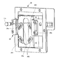
- the ampoule cutter 31 has a file part 31a for notching the neck of the ampoule that is the drug container 10, as shown in FIG.
- the first robot arm 21 grasps the body part below a certain distance from the neck.
- the dimension information of each part of the ampule can be acquired from the master table.
- the first robot arm 21 rubs the ampoule's neck against the file portion 31a.
- the shavings produced during the notching process are received by the waste tray 31b.
- the first robot arm 21 inserts a notched ampule into the hole 31d of the head insertion portion 31c from below, and projects the head above the neck upward.
- a pusher 31e is provided in the head insertion part 31c so as to be located on the side of the head.
- a cam acting on the rear end of the pusher 31e is provided in the drive box 31f. When the cam rotates once, the pusher 31e reciprocates once by the operation of the cam. The cam is rotated by a motor (not shown) provided in the drive box 31f.
- the controller 500 causes the first robot arm 21 to protrude the head of the ampule upward from the hole 31d, and then moves the pusher 31e in a direction to push the head.
- the moving pusher 31e pushes and breaks the head, and the broken head falls into the waste box 31g.
- the controller 500 can execute an operation of causing the first robot arm 21 to grip the waste box 31g and throwing the head into the garbage bag 135, for example, after the end of one mixed injection process.
- waste tray 31b waste can be discarded by the operation of the first robot arm 21.
- the ampoule cutter 31 is provided with a handle 31h, and a person can move on the rail 31i (see FIG. 3) by a human operation so that a person can dispose of the waste in the waste tray 31b and the waste box 31g. It is like that.
- the head is folded by moving the pusher without moving the ampoule with the head of the ampoule inserted into the hole 31d. Since the head is folded with the head of the ampoule inserted into the hole 31d of the head insertion part 31c, the glass piece generated when the head is broken is received by the head insertion part 31c, and the glass piece is inside the ampoule. It is prevented from falling into the liquid medicine. Further, since the ampoule is not moved when the head is folded, the size of the hole 31d can be made such that there is almost no gap when the ampoule head is inserted and pressed. When the gap is eliminated in this way, it is possible to prevent the glass piece from falling into the ampoule from the gap.
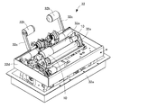
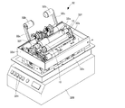
- the stirring device 32 includes two rollers 32a that are spaced apart and rotate in the same direction.
- the driving roller 32a is rotationally driven by a motor.
- the vial container as the drug container 10 is placed between the rollers 32a and the roller 32a is rotated, the vial bottle is rotated and agitation is performed. Such agitation is performed when an infusion is injected into the vial bottle to dissolve the powdered drug to produce a liquid drug.
- the roller 32a is formed long in the axial direction, and can simultaneously stir two vials. Further, at least one of the rollers 32a is driven eccentrically, and the vial is also stirred in the vertical direction (vertical direction).
- the roller 32a or the entire stirring device may be tilted so that stirring is performed in the tilted state.
- the stirring device 32 has a holding part 32b that holds the vial.
- the pressing portion 32b is made of a driven roller, for example.
- the pressing portion 32b is moved by a rotation support portion 32c that is rotated by a motor.
- the support base 32d that supports the roller 32a and the like is supported by a horizontal swing mechanism 32e.
- the horizontal swing mechanism 32e can swing the support base 32d horizontally by a crank mechanism, for example.
- support portions 32f having U-shaped cutouts are provided.
- the vial may be determined whether or not the vial is rotating by detecting the rotation of the driven roller.
- the first robot arm 21 may be operated so as to grasp the vial after the stirring operation is completed and bring it to the vicinity of the main door 301 to show the vial to the inspector.
- the controller 500 can instruct the controller 500 to perform an additional stirring operation.
- the controller 500 operates the first robot arm 21 to place the vial on the stirring device 32.
- the controller 500 causes the first robot arm 21 to perform an operation of causing the inspector to show the vial after operating the stirring device 32 for an additional time.
- the stirring operation is terminated.
- the controller 500 When the controller 500 receives the end instruction, the controller 500 stores the additional stirring operation and the drug in association with each other, and determines whether or not to increase the stirring time in advance when there is a prescription for the same drug next time. Execute processing to ask the inspector.
- the controller 500 can perform a process of lengthening the stirring time when the inspector performs a yes operation on the question.
- the roller 32a may be divided into a plurality of regions in the longitudinal direction, one region may be an eccentric stirring (vertical stirring) region, and the other region may be a non-eccentric stirring (non-vertical stirring) region. If vertical stirring and non-longitudinal stirring can be performed, the master table determines whether vertical stirring is permitted in the drug to be stirred, and non-longitudinal stirring may be performed for drugs that are not allowed to be stirred vertically. Good.
- three or more rollers 32a may be provided to increase the number of vials that can be stirred simultaneously. When three or more are provided as described above, the vertical stirring region and the non-vertical stirring region can be formed without dividing the region in the longitudinal direction as described above.
- the user may customize the initially registered stirring time, roller rotation speed, and horizontal or vertical stirring amplitude.
- an alarm may be issued when the temperature in the mixed injection processing chamber 104 falls below a threshold value. According to this, it is possible to prevent undissolution from occurring due to the low temperature.
- the needle tip of the injection needle 11c with a cap is inserted upward into the hole 43b of the chuck portion 43a in which the cut portion is formed.
- the motor 43c is driven, the hole 43b of the chuck portion 43a is expanded by a cam mechanism (not shown), and the injection needle 11c with the cap can be inserted.
- driving of the motor 43c is stopped, the holding state of the capped injection needle 11c is maintained by the spring 43d.
- the needle turning motor 43e is driven, the gear 43f and the gear 43g rotate, the chuck portion 43a rotates, and the capped injection needle 11c rotates.
- the injection needle attaching / detaching apparatus 43 may be provided so that the needle tip of the injection needle 11c to be mounted may be oriented obliquely upward or horizontally.
- cap attachment / detachment An example of cap attachment / detachment is shown below.
- the first robot arm 21 inserts the injection needle 11c with the cap into the injection needle attaching / detaching device 43, and the injection needle attaching / detaching device 43 holds the injection needle 11c with the cap.
- the second robot arm 22 applies the syringe body 11 a to the injection needle 11 c held by the injection needle attaching / detaching device 43.
- C The injection needle 11c with a cap is rotated by the injection needle attaching / detaching device 43, and the injection needle 11c is attached to the syringe body 11a.
- the cap remains gripped by the injection needle attaching / detaching device 43.
- the second robot arm 22 inserts the injection needle 11c of the syringe main body 11a with the injection needle 11c into the cap held by the injection needle attaching / detaching device 43.
- the injection needle attaching / detaching device 43 releases the holding of the syringe body 11a with the injection needle 11c. The syringe body 11a with the injection needle 11c is discarded as garbage.
- the following operation may be performed.
- the first robot arm 21 takes out the cap gripped by the injection needle attaching / detaching device 43 from the injection needle attaching / detaching device 43 and the mixed injection process is completed, the first robot arm 21 becomes the second robot arm 22.
- Steps (a) to (e) are as described above.
- the second robot arm 22 inserts the syringe body 11a with the injection needle 11c into the cap held by the injection needle attaching / detaching device 43.
- the cap is rotated by the injection needle attaching / detaching device 43 to remove the injection needle 11c from the syringe body 11a.
- the medicine barcode reader 34 includes rollers 34a that are spaced apart and rotate in the same direction.
- the driving roller 34a is rotationally driven by a motor or the like.
- the medicine container 10 is placed between the two rollers 34a and the roller 34a is rotated, the medicine container 10 is rotated once and the entire label can be directed to the reader portion 34b.
- a syringe stand 35a is placed on the weighing scale 35.
- the measurement result of the weighing scale 35 is notified to the controller 500.
- the controller 500 By measuring with the syringe 11 using the weighing meter 35, the amount of liquid medicine actually extracted (weight of the liquid medicine-filled syringe 11-weight of the known empty syringe 11) can be measured.
- the syringe mounting table 35a holds the syringe 11 obliquely upward so that liquid leakage is unlikely to occur during weighing.
- a cover 35b is provided on the upper surface of the main body portion of the weighing meter 35 so that the main body portion is difficult to touch the air in the mixed injection processing chamber 104.
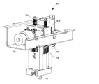
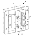
- the needle bending detection unit 36 includes a first optical sensor 361 and a second optical sensor 362 that are arranged so that their rays are not parallel to each other. Each optical sensor includes a light emitting unit and a light receiving unit.
- the needle bending detection unit 36 is formed with a long hole 36a into which the injection needle 11c is inserted and moved.
- the second robot arm 22 inserts and moves the injection needle 11c attached to the syringe 11 into the elongated hole 36a before inserting it into the mixed injection port of the infusion bag 12.
- the first optical sensor 361 and the second optical sensor 362 are turned off. By using the position information of the injection needle 11c when blocking the light beam, the bending of the injection needle 11c can be detected.
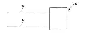
- FIG. 24 shows the reference member 363.
- the reference member 363 is provided with a straight reference needle N and a reference needle M with a distance E therebetween.
- the reference needle N and the reference needle M of the reference member 363 are inserted into the elongated hole 36a and moved by the operation of the second robot arm 22. By this movement, the light beam is blocked by the reference needle N and the reference needle M.
- the controller 500 stores the position information of the reference needle N and the reference needle M when blocking the light beam as known information in the storage unit.
- FIG. 25 is an explanatory diagram of needle bending detection.
- the second robot arm 22 positions the reference needles N and M at a predetermined start point of the needle bending detection unit 36, and at the same time in the Y direction (
- the reference member 363 is moved in a direction that is not parallel to the light beam of the first optical sensor 361 and the light beam of the second optical sensor 362.
- the position data (distance data) of the points a1 and a2 and the points b1 and b2 can be acquired based on the speed of the movement and the timer values when the sensors 361 and 362 are turned on / off.
- the distance from the a1 point to the a2 point is A, and the distance from the b1 point to the b2 point is C. Further, the interval between the reference needles N and M is E, and if the position through which the reference needle N passes is defined as the reference point position in the X direction, the reference needle M passes through the point E from the reference point position in the X direction.
- the second robot arm 22 grips the syringe 11 used in the actual mixed injection process, and the injection needle 11c is positioned at a predetermined start point of the needle bending detection unit 36.
- the start point is a position (originally on the path) that is a distance Xc from the origin position in the X direction. Further, the light beams of the sensors 361 and 362 are blocked at the needle tip side of the injection needle 11c.
- the second robot arm 22 moves the injection needle 11c in the Y direction at a constant speed simultaneously with the timer start.
- the position data (distance data) on the original path when the needle tip approaches the point a3 and b3 on the injection needle detection path based on the speed of this movement and the timer value when the sensors 361 and 362 are turned on / off. ) Can be obtained.
- the needle tip side is bent with respect to the center of the injection needle 11c when viewed from the syringe plunger 11b side.
- the needle tip side passes through the injection needle detection path that originally deviates from the path.
- the injection needle detection path is at a distance Xp from the reference point position in the X direction
- the bending component in the X direction of the injection needle is represented by Xc ⁇ Xp.
- the bending component in the Y direction of the injection needle 11c is represented by ⁇ .
- the controller 500 operates the second robot arm 22 so that the needle tip position when puncturing the co-infusion port of the infusion bag 12 is corrected based on the obtained needle bending amount. Thereby, an injection needle can be stabbed in the aimed position.
- the needle bending inspection may be performed once for a new injection needle 11c, or may be performed multiple times when the injection needle 11c is inserted into the mixed injection port of the infusion bag 12 multiple times. Good.
- the thickness of the injection needle 11c can be determined from the time required to pass the light beam (sensor-off time interval), and misuse of the injection needle 11c can also be determined.
- the first optical sensor 361 is provided with a rotating plate that rotates, for example, about 45 ° in a plane, and the rotating plate is rotated so as not to shield the elongated hole 36a, the first optical sensor 361 is moved to the second light.
- the sensor 362 can be used instead. In this case, the reference needle and the injection needle 11c are moved in a plurality of times.
- the bending of the injection needle in the X direction and the Y direction is detected using the two optical sensors 361 and 362, but the bending of the injection needle in the X direction and the Y direction is detected by one optical sensor. Also good.
- the bending in the X direction can be detected by one sensor (in this case, the optical sensor 361) because Xp is obtained from the ratio of the distances a1 to a2 and the distances a3 to a2 in FIG.
- the direction of the syringe 11 is rotated 90 degrees around the axis of the syringe 11 by the second robot arm 22 or the like, and the syringe 11 is again moved along the original path as shown in FIG. .
- the bending in the X direction can be detected by one optical sensor, but since the syringe 11 is rotated 90 degrees, the detected bending is the bending in the Y direction.
- the needle 11c may be detected by imaging the injection needle 11c with a camera and recognizing the captured image.
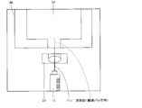
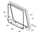
- the controller 500 images the direction of the needle insertion confirmation transparent window 38 with the needle insertion confirmation camera 44 when the mixed injection port of the infusion bag 12 is punctured with the injection needle 11c.
- the needle insertion confirmation camera 44 images the infusion bag 12 located outside the mixed injection processing chamber 104 and the syringe 11 (injection needle 11c) in the mixed injection processing chamber 104 so as to fit in one image.
- An example of a captured image at this time is shown in FIG. From this image, it can be confirmed whether or not the distal end side of the injection needle 11c is located in the infusion bag 12. This image can be displayed on the touch panel monitor 14, for example.
- the image is stored in the storage unit for final inspection.
- the second robot arm 22 moves the syringe 11 sucked in the infusion solution to a position where it can be imaged by the syringe confirmation camera 42.
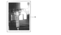
- the controller 500 images the syringe 11 with the syringe confirmation camera 42.
- An example of a captured image at this time is shown in FIG. From this image, it is possible to confirm the presence or absence or amount of infusion in the injection needle 11c. This image can be displayed on the touch panel monitor 14, for example. The image is stored in the storage unit for final inspection.
- the infusion bag 12 in which the co-infusion process is appropriately completed by operating the OK button on the touch panel monitor 14 on which the image is displayed is lowered by the infusion bag ascending / descending inclined portion 113. Then, when the OK button is operated as described above, and further when the final audit OK button is operated, the controller 500 releases the lock for opening and closing the adjustment container take-out door 15. In other words, the adjustment container take-out door 15 cannot be opened unless an inspection is performed by a person. Of course, the adjustment container take-out door 15 can be opened for error processing.
- the dispensing can also be performed in the state of the syringe 11 using the syringe ejection door 302.
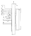
- the syringe outlet door 302 has a front door portion 302a and a rear door portion 302b positioned in an L shape, and is rotated by a vertical axis hinge 302c.
- an opening leading to the mixed injection processing chamber 104 is opened and closed.
- the syringe take-out door 302 is opened so that a syringe stand 302e provided on the back surface of the front door portion 302a is positioned outside the mixed injection processing chamber 104, and the opening is closed by the back door portion 302b. It has become.
- the opening and closing of the syringe take-out door 302 is performed by a person holding the knob 302d.
- the supply port of the air supply system for supplying clean air to the mixed injection processing chamber 104 is formed in the ceiling of the mixed injection processing chamber 104, and the mixed injection processing chamber 104 has a negative pressure.
- a suction slit 104 b is formed on the side surface of the mixed injection processing chamber 104.
- the syringe outlet door 302 is provided at a position for receiving an air flow from the ceiling toward the slit 104b.
- the syringe take-out door 302 is provided at a position above the slit 104b, and a dedicated suction slit 104c for the syringe take-out door 302 is provided at a position above the slit 104b.
- the dedicated suction slit 104 c is formed at a height position overlapping the height region of the syringe extraction door 302 or at a position lower than the syringe extraction door 302.
- the horizontal interval K between the side wall where the dedicated suction slit 104c (the slit 104b) is formed and the back door 302b is preferably within 200 mm (preferably within 150 mm or 100 mm).
- the syringe outlet door 302 may be configured to rotate the L-shaped door with a horizontal hinge.
- the horizontal interval between the slit side edge of the L-shaped door and the side wall where the slit 104b is formed is preferably within 200 mm (preferably within 150 mm or 100 mm).
- control may be performed to increase the suction force of both or one of the dedicated suction slit 104c and the slit 104b for a certain period of time.
- the present invention is not limited to providing the syringe outlet door 302 on the main door 301. Moreover, you may provide the said syringe stand 302e in the front side of the back door part 302b.
- the syringe 11 (syringe body 11a) is temporarily placed on the temporary placement shelf 33 with the neck portion facing downward in a state where the injection needle 11c is not attached.
- the temporary storage shelf 33 is formed with a neck holding hole into which the neck portion is fitted. Since the diameter of the neck is substantially constant regardless of the capacity of the syringe 11, the neck holding hole is not dedicated to each syringe body 11a, but a common neck holding hole having a predetermined diameter is provided.
- the temporary storage shelf 33 may be provided at a position accessible by both the first robot arm 21 and the second robot arm 22. Further, since the temporary storage shelf 33 is not provided on the bottom surface of the mixed injection processing chamber 104, the bottom surface of the mixed injection processing chamber 104 can be flattened.
- the container transport unit 110 transports the adjustment container 101 from a position close to the first robot arm 21 to a position close to the second robot arm 22.
- at least one of the first robot arm 21 and the second robot arm 22 is operated. This operation is, for example, an operation of attaching the injection needle 11c to the syringe body 11a by the first robot arm 21 and the second robot arm 22.
- preparation for mixed injection processing is advanced in the mixed injection processing chamber 104 using the time for transporting the adjustment container 101 from a position close to the first robot arm 21 to a position close to the second robot arm 22.
- the working time can be reduced.
- the container transport unit 110 transports the adjustment container 101 from a position close to the first robot arm 21 to a position close to the second robot arm 22.
- the communication opening 114 (adjustment container inlet) and the adjustment container take-out door 15 (adjustment container outlet) are arranged so as to sandwich the main door 301 or the garbage storage chamber door 13.
- the adjustment container inlet and the adjustment container outlet are adjacent to each other, it is easy to make an error between the inlet and the outlet.
- the main door 301 or the garbage storage chamber door 13 is sandwiched between the above. If the adjusting container inlet and the adjusting container outlet are arranged, it is difficult to make an error as an inlet or an outlet.
- the adjustment container take-out door 15 (adjustment container outlet) may be formed on the left side surface of the main body 300.
- the communication opening 114 (adjustment container inlet) may be formed on the front surface of the main body 300.
- the stirring device 32 is provided on one side of the dust cover 132a (the arrangement side of the first robot arm 21), and the other side of the dust cover 132a (the arrangement side of the second robot arm 22).
- the dust lid 132a is designed to be accessible to both the first robot arm 21 and the second robot arm 22, while the agitation is performed. Since the device 32 is accessed only by the first robot arm 21, the optimum design can be performed in consideration of the operation characteristics of the container holding unit 25, and the second robot arm is also used for the weighing device 35. Since only 22 are accessed, an optimum design can be performed in consideration of the operation characteristics of the syringe operation unit 26.
- the syringe 11 weighed by the balance is transferred to the infusion bag 12 without passing between the first and second robot arms 21 and 22. Since it can be inserted, it is efficient.
- the germicidal lamps 45, 45 are turned on, for example, about 3 hours before the start of the mixed injection process. Since one of the sterilizing lamps 45 and 45 is provided at a position between the first and second robot arms 21 and 22, the amount of sterilizing light blocked by the first and second robot arms 21 and 22 And the inside of the mixed injection processing chamber 104 can be sterilized evenly.
- the label may be peeled off. Therefore, it is better to hold the drug container 10 with a weaker force than the drug container 10 without the label. Even if it is gripped with a weak force, it is difficult to slip because of the label.
- the presence or absence of the label can be known from the information in the master table.
- two robot arms 21 and 22 are provided in the mixed injection processing chamber 104, but three or more robot arms may be provided in the mixed injection processing chamber 104.
- the first and second robot arms 21 and 22 may be provided on a rotatable disk 28.
- the positions of the first and second robot arms 21 and 22 with respect to the mixed injection processing chamber 104 are changed while maintaining the positional relationship of the first and second robot arms 21 and 22. This makes it easy to perform detailed work using the first and second robot arms 21 and 22.
- a stirrer 32 can be arranged on the control box 320 to constitute a stand-alone stirrer.
- the control box 320 is provided with various buttons 321 such as a roller rotation speed adjustment button, an agitation time setting button, a roll on / off button, and a vertical shake on / off button, and a volume.
- the mixed injection process is performed by the robot arms 21 and 22.
- the operation of holding and rotating the syringe 11 is performed using the rotation mechanism of Patent Document 1 or Patent Document 2.
- the mixed injection process may be performed.
- the mixed injection device 1 has two power supply systems. One system is usually used (when there is no power outage). The other system is used to receive power supply from a standby power source of a medical facility where the co-infusion apparatus 1 is installed during a power failure.
- the mixed injection device 1 has a function of detecting the occurrence of a power failure. Generation
- production of a power failure can be judged by whether the electric power supply from said one system
- the mixed injection device 1 When a power failure occurs, if the process (for example, the process from reading the IC tag of the adjustment container 101 to injecting the mixed solution into the infusion bag 12) is being performed, the mixed injection device 1 The system is used to receive power from the standby power supply, and the process being executed is completed and then stopped. Thereby, the process does not end in the middle. Moreover, when the co-infusion apparatus 1 is stopped and there is another prescription to be co-injected, the power consumption of the standby power source can be suppressed by performing the co-infusion process manually.
- the mixed injection device 1 increases the suction force of the slit 104b when the shutter 111 in the mixed injection processing chamber 104 is open, and lowers the pressure in the mixed injection processing chamber 104 than when the shutter 111 is closed. May be. According to this, when the shutter 111 is opened, it is possible to more reliably prevent the air in the mixed injection processing chamber 104 from exiting to the container transport unit 110. Similarly to the above, when the mixed injection communication port 37 is provided with a shutter, when the shutter of the mixed injection communication port 37 is opened, the suction force of the slit 104b is increased compared to when the shutter is closed. The pressure in the mixed injection processing chamber 104 may be lowered.
- the co-infusion apparatus 1 when the sealed dust cover 132a is opened, the co-infusion apparatus 1 has an exhaust path 133 on the side surface of the dust communication tube 132 and an exhaust path 134 provided in the dust storage chamber 13a, rather than when it is closed.
- the suction force may be increased to more reliably prevent air from flowing into the mixed injection processing chamber 104 from the garbage bag and the dust storage chamber 13a.
- first and second robot arms 21 and 22 may be provided with the drug barcode reader 34 and a load cell for measuring the weight of the drug.
- the load cell when the load cell is used, when the drug is extracted with a syringe, the weight of the drug extracted on the spot can be detected.
- a load cell for measuring the weight of the infusion bag may be provided in the hook portion 113a of the infusion bag ascending / descending inclined portion 113, and a load cell for measuring the weight of the medicine container may be provided in the medicine barcode reader 34. If the drug extraction weight is measured by the load cell of the drug barcode reader 34 and the measured weight of the load cell of the infusion bag ascending / descending inclined portion 113 is increased by that amount, it can be determined that normal mixed injection has been performed. In the case of this configuration, the weighing meter 35 in the mixed injection processing chamber 104 can be omitted.
- the mixed injection port may be cleaned with a cleaning tool after the mixed injection.
- the cleaning tool placed in the mixed injection processing chamber 104 may be grasped by the second robot arm 22 and cleaned by the operation of the second robot arm 22.
- the second robot arm 22 directly grips the disposable cleaning tool stored in the adjustment container 101 or indirectly through the first robot arm 21, and the second robot arm 22. It is conceivable to clean by the operation of.
- the disposable cleaning tool can be temporarily placed on the temporary shelf 33. You may discard a used disposable cleaning tool in the said trash box 131.
- disinfecting tools or disposable disinfecting tools are prepared, and these disinfecting tools are gripped by the first robot arm 21 or the second robot arm 22, and by the operation of these robot arms, a mixed injection port, a syringe or the like is set before mixing. You may make it disinfect. Further, these robot arms may be sterilized with each other.
- first and second robot arms 21 and 22 and the stirring device 32 are operated at the same time, for example, while the stirring device 32 is stirring the drug that requires stirring, Operations such as injection into the infusion bag 12 may be performed by the first and second robot arms 21 and 22.
- the ampule is grasped by the first robot arm 21 or the second robot arm 22, and a small amount of liquid medicine present in the head (neck portion) of the ampule is moved into the main body by rotating the ampule. After dropping, the head of the ampule may be cut with the ampule cutter 31.
- the ampoule may be melt-cut with a hydrogen gas flame. Since the combustion of hydrogen gas only generates water, the mixed injection processing chamber is not particularly polluted. Moreover, since it is a fusion cut, there is an advantage that shavings do not occur.
- the bending detection result can be used for the operation of inserting the injection needle 11c into the needle cap. . That is, as shown in FIG. 31A, if the center of the base of the injection needle 11c and the center of the entrance of the needle cap 11d are aligned, the needle tip may not enter the entrance of the needle cap 11d. Therefore, based on the degree of bending of the injection needle 11c, the relative position of both is corrected so that the tip of the injection needle 11c is positioned at the center of the needle cap 11d so that the needle tip is positioned at the center of the entrance of the needle cap 11d.
- the tip of the injection needle 11c is put into the needle cap 11d. Then, after inserting the injection needle 11c halfway, a moving operation is performed to match the center of the base of the injection needle 11c and the entrance center of the needle cap 11d until the end. This operation can be performed using the second robot arm 22 and the injection needle attaching / detaching device 43, for example.
- the needle cap 11d is a molded product and is somewhat distorted depending on the manufacturer, there is a case where the needle 11c does not enter even if the needle 11c is inserted straight into the opening of the needle cap 11d.
- FIG. 31 (B) it is desirable to position the needle tip at the center of the opening with the axis of the injection needle 11c inclined, and to insert deeply while gradually returning the oblique state to straight. . According to this, although depending on the direction of the cut surface of the needle tip, the proportion of proper insertion increases.
- the first and second robot arms 21 and 22 are disposed in the mixed injection processing chamber 104, but the present invention is not limited to this.
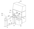
- the mixed injection apparatus uses a general safety cabinet 104A, and the floor-mounted robot arms 21A and 22A are used as the first and second robot arms 21 and 22 as the safety cabinet.
- a structure may be adopted in which the first and second robot arms 21A and 22A are placed outside the 104A and inserted into the mixed injection processing chamber of the safety cabinet 104A through the opening.
- FIG. 32 the mixed injection apparatus uses a general safety cabinet 104A, and the floor-mounted robot arms 21A and 22A are used as the first and second robot arms 21 and 22 as the safety cabinet.
- a structure may be adopted in which the first and second robot arms 21A and 22A are placed outside the 104A and inserted into the mixed injection processing chamber of the safety cabinet 104A through the opening.
- the first and second robot arms 21 ⁇ / b> A and 22 ⁇ / b> A may be provided on a rotatable turning support portion 28 ⁇ / b> A on the main body portion 23. That is, the first and second robot arms 21 ⁇ / b> A and 22 ⁇ / b> A may be double-arm robots having a turning axis in the main body 23. Further, each of the first and second robot arms may be driven by seven or more axes. When the first and second robot arms 21A and 22A are mixedly injected in the mixed injection processing chamber, the first and second robot arms 21A and 22A may be exposed to the medicine.
- the first and second robot arms 21A, 22A exposed to the medicine are taken out of the mixed injection processing chamber without being processed, it is dangerous. Therefore, after cleaning the first and second robot arms 21A and 22A, such as sterilizing the first and second robot arms 21A and 22A with the sterilization lamp 45, the first and second robot arms 21A and 22A are mixedly injected. It is preferable to leave the processing chamber. Further, the first and second robot arms 21A and 22A may be cleaned outside the mixed injection processing chamber immediately before being put out of the mixed injection processing chamber. Since the first and second robot arms 21A and 22A are put into the mixed injection processing chamber after removing the adhering substances outside the mixed injection processing chamber, the mixed injection processing chamber is not contaminated and the mixed injection can be performed in a safe state.
- a rail mechanism 24 may be provided for moving the first and second robot arms 21A and 22A together with the main body 23 toward and away from the safety cabinet 104A.
- an adjustment container 101A in which a syringe or the like is set is placed on a table 305 disposed in the vicinity of the first and second robot arms 21A and 22A, and the adjustment container 101A is placed on the safety cabinet by the robot arm or conveyor. You may make it carry in 104A. Then, the mixed infusion bag may be returned to the same adjustment container 101.
- a configuration may be adopted in which an adjustment container in which medicines and infusion bags for each patient are set is stored in a stocker.
- a stocker 306 is provided, and as soon as the adjustment container 101 in which a medicine and an infusion bag for each patient are set, it is inserted from the inlet 306a.
- Each adjustment container 101 is provided with a wireless tag (RFID or the like), a barcode or the like for each patient, and the stocker 306 can manage which patient's adjustment container 101 is stocked at what level. it can.
- the stocker 306 moves the adjustment container 101 of the patient to the height of the communication opening 114 of the main body 300, for example, using a conveyor or the like.
- the adjustment container 101 is put into the communication opening 114.
- the infusion bag 12 includes a plastic bottle made of a hard material in addition to a flexible film body. Since this plastic bottle does not swell, when a liquid medicine is put into a plastic bottle at atmospheric pressure, the inside of this plastic bottle becomes positive pressure. Such positive pressure may cause the liquid medicine to jump out of the plastic bottle when the nurse inserts the needle into the rubber stopper of the plastic bottle for infusion work.
- the air or the replacement fluid is extracted from the plastic bottle with a syringe, and the inside of the plastic bottle is set to a negative pressure. Then, for example, the ampule liquid medicine is extracted into the syringe 11 and the liquid medicine is put into the plastic bottle in the negative pressure state using the syringe 11.
- the syringe 11 at the time of injection (a state in which the plunger 11b is pushed into the syringe body 11a) can be imaged by the syringe confirmation camera 42.
- the number of needle sticks is increased by the amount that the needle is inserted into the rubber stopper just to remove air or the like from the plastic bottle. Note that an empty container may be set in the adjustment container 101, and the replacement fluid extracted in the empty container may be discarded.
- the problem in the case of using the plastic bottle also occurs when the infusion bag 12 of a flexible film body is fully inflated. Also, which method is to be used may be written in the prescription content information, and either method may be executed based on this prescription content information.
- FIG. 34 shows a modification of the container holding unit 25 in the first robot arm 21.
- the container holding part 25 is a combination of the above-mentioned medicine by two-point contact of one gripping claw 25a by a substantially V-shaped concave gripping part 25b and two-point contact of the other gripping claw 25a by a substantially V-shaped concave gripping part.
- the body part of the container 10 is held.
- the concave gripping portion 25b is supported by, for example, a pin 25c whose axial direction is set in a direction orthogonal to the moving direction (gripping operation direction) of the gripping claw 25a, and rotates in a plane including the gripping motion direction. Can move.
- the first robot arm 21 has a pair of concave gripping portions 25b that come into contact with each other when the drug container 10 is held, and one concave gripping portion 25b is movably provided.
- one concave gripping portion 25b may be movably provided by an elastic member.
- the drug container 10 can be appropriately held by making the concave gripping portion 25b rotatable. Further, even if the contact for holding the medicine container 10 may not be properly performed due to the irregularity of the medicine container 10 or the thickness of the label, the concave gripping portion 25b rotates in the gripping direction surface. The said contact comes to be performed appropriately and the chemical
- the concave gripping part 25b which is a movable part that moves by contacting the drug container 10, is provided in both the ampoule gripping part on the distal end side and the vial gripping part on the base side. It is not restricted to such a configuration.
- a member is detachably provided in the mixed injection processing chamber 104, and at least one robot arm 21, 22 performs an operation of grasping the member in order to confirm the presence / absence of the member. Also good. According to this, when the said member is grasped
- the grip position with respect to the member is registered in advance as coordinate data, and the controller 500 moves the robot arm to a location indicated by the coordinate data.
- the distance between the pair of gripping claws 25a of the container holding portion 25 becomes zero. Therefore, when it is determined that the distance between the pair of gripping claws 25a is zero or smaller than the thickness of the member based on the operation state (number of drive pulses, driving time, etc.) of the motor 251 that drives the gripping claws 25a. It is determined that is not attached.
- the member include the syringe placing table 35 a placed on the weighing meter 35 and a member set on the temporary placing shelf 33. The above operation is performed, for example, between the time when the power supply of the mixed injection device is turned on and the start of the mixed injection operation.
- a needle tip detection unit 39 for detecting the axial tip position of the injection needle 11c attached to the syringe 11 is provided. May be. According to this, it is possible to determine an accurate distance from the gripping position of the syringe 11 by the second robot arm 22 to the tip of the injection needle 11c.
- the needle tip detection unit 39 an area sensor including a light emitting unit 39a and a light receiving unit 39b so as to be orthogonal to the axial direction of the injection needle 11c can be used.
- the controller 500 monitors the output of the needle tip detection unit 39 while gradually moving the syringe 11 in the direction of the needle axis by the second robot arm 22, and operates the syringe when the output is displaced.
- the tip position of the injection needle 11c with respect to the syringe gripping position of the portion 26 can be determined.
- the controller 500 can correct subsequent operations using the difference as a correction value. This correction can improve the extraction accuracy of the liquid medicine.
- the needle tip detection unit 39 can be provided in a place other than the location of the needle bending detection unit 36.
- the second robot arm 22 is necessary for sucking in a larger liquid volume than the liquid volume defined by the prescription content information when the infusion or liquid medicine is sucked into the syringe 11 by the syringe operation unit 26.
- a pulling operation may be executed. According to this, even when the tip rubber does not move according to the pulling amount of the plunger 11b due to friction between the tip rubber of the plunger 11b and the inside of the syringe body 11a, the syringe operation unit 26 causes the plunger 11b to move. After performing the pulling operation, the plunger 11b is returned by the syringe operation unit 26 to the position where the prescribed liquid amount is obtained, so that the prescribed liquid amount can be reliably taken into the syringe body 11a. .
- the plunger 11b should be pulled by an extra 3 mm, for example, than the pull amount required to suck the liquid amount specified by the prescription content information. Set in advance. Then, the second robot arm 22 pushes the plunger 11b by 3 mm after the infusion process of the infusion or liquid medicine by the syringe operation unit 26.
- the accuracy of the weighing scale 35 may be increased as the amount of liquid sucked into the syringe 11 increases.
- the higher the accuracy of the weighing meter 35 the longer the time required for measurement.
- the greater the amount of liquid sucked into the syringe 11 the lower the required accuracy. Therefore, if the accuracy of the weighing meter 35 is increased as the amount of liquid sucked into the syringe 11 is increased, the measurement time when the accuracy of the weighing meter 35 is fixed regardless of the amount of the liquid is avoided. Can do.
- the accuracy of the weighing scale 35 can be changed by switching the range that the weighing scale 35 originally has.
- the controller 500 determines the amount of liquid to be sucked into the syringe 11 based on the prescription content information, selects the first range when the amount of liquid exceeds 50 ml, and when the amount of liquid is 50 ml or less, A second range with higher accuracy than the first range is selected.
- the switching is not limited to two stages, and three or more stages may be switched.
- the range may be changed according to the increase. It is also possible to change the accuracy of the weighing meter 35 without changing the range of the weighing meter 35.
- the controller 500 waits for the first digit after the decimal point to converge and acquires the measured value.
- the controller 500 obtains the second digit after the decimal point.
- the measured value may be acquired after the convergence of the numerical value.
- the number of digits for waiting for the convergence of the numerical value may be changed according to the weight of the measurement object (the lighter the number of digits for waiting for convergence is increased).
- the operation of pushing the plunger 11b of the syringe 11 into the syringe body 11a in the mixed injection processing chamber 104 is executed. You may do it. According to this, even when a gap exists between the distal end of the plunger 11b of the syringe 11 placed in the mixed injection processing chamber 104 and the distal end side in the syringe body 11a, the gap is eliminated. Can do. If the gap exists, the starting point position (origin position) for sucking infusion or liquid medicine is shifted, and an accurate suction operation is not executed. On the other hand, if it is said structure, exact suction operation can be performed.
- the determination that the plunger 11b of the syringe 11 is completely pushed into the syringe body 11a in the mixed injection processing chamber 104 is made, for example, by a drive motor of the moving unit 263 of the plunger holding unit 262 in the syringe operation unit 26. This may be performed when the torque generated in the above reaches a predetermined value. Further, the execution timing of the clearance elimination operation may be any time before the operation of aspirating the infusion or liquid medicine with the syringe 11 placed in the mixed injection processing chamber 104. It may be performed before the injection needle 11c is mounted, or may be performed after the injection needle 11c is mounted.
- the clearance elimination operation is performed using the moving unit 263 of the plunger holding unit 262 in a state where the second robot arm 22 holds the syringe main body 11a of the syringe 11 by the syringe operating unit 26. Also good. According to this, the operation
- the clearance clearance operation may be performed with the pair of gripping claws 262a holding the collar part of the plunger 11b sandwiched between the collar parts, or without a pair of gripping claws. In a state where 262a is closed, the gripping claw 262a may be pressed against the flange and the plunger 11b may be pushed into the syringe body.
- the controller 500 may perform the following processing.
- the adjustment container 101 holds the medicine tray 102 so as to be movable, and the medicine tray 102 can face the mixed injection processing chamber 104.
- the adjustment container 101 is provided with an infusion bag holding portion 103 for holding the medicine tray 102 and the infusion bag 12 so as to be removable.
- the controller 500 moves the medicine tray 102 from the adjustment container 101 set at the set position into the mixed injection processing chamber 104, and moves the medicine tray 102 into the mixed injection processing chamber 104.
- a process of passing the infusion bag holding portion 103 to the infusion bag lifting and lowering inclined portion 113, which is a holding operation portion for holding the infusion bag for needle sticking from the adjustment container, and a state without the infusion bag holding portion 103 The process of returning the adjustment container 101 to the set position and the process of returning the medicine tray 102 to the adjustment container 101 returned to the set position are performed.
- the said syringe 11 and the medicine container 10 are the said medicine tray.
- the infusion bag holding unit 103 can be transferred to the infusion bag ascending / descending inclined portion 113 while performing the process of taking out from 102 and the process of setting the syringe 11 on the second robot arm 22.
- the infusion bag holding portion 103 can already be delivered to the infusion bag up-and-down tilting portion 113, so that the second robot arm 22
- the process of sucking infusion from the infusion bag 12 with the set syringe 11 can be executed quickly.
- the empty medicine tray 102 can be returned to the adjustment container 101 returned to the set position.
- the above process may be executed only when the drug container (vial bottle) 10 in which powder is placed is set on the drug tray 102 and the infusion bag 12 is set on the adjustment container 101. . Further, the controller 500 can determine the condition based on the prescription content information.
- a tray lifting / lowering unit 112 that lifts and lowers the drug tray 102 is provided.
- the tray lifting / lowering unit 112 is configured to move the drug tray 102 by, for example, four shafts 112a that can be moved up and down. Lifted from below. Further, a through hole through which the four shafts 112a pass is formed in the lower surface of the adjustment container 101.
- a support claw portion (not shown) that supports the edge of the drug tray 102 after the shaft 112a lifts the drug tray 102 from below is provided in the container transport unit 110.
- the support claw can be moved by an actuator such as an electromagnetic solenoid.
- the adjustment container 101 can be moved on the container transport part 110 by lowering the shaft 112a.
- the shaft 112a is raised to support the medicine tray 102, and after the support claw portion is retracted, the shaft 112a is lowered to lower the shaft 112a.
- the medicine tray 102 can be returned to the adjustment container 101. Further, if a groove for allowing the shaft 112a to pass through is formed in the container transport unit 110, the container 102 is left in the mixed injection processing chamber 104 without lowering the shaft 112a.
- the conveyance unit 110 can be moved.
- the drug tray 102 may be moved downward when a predetermined load or more is received from above in a state where the drug tray 102 is faced (appeared) in the mixed injection processing chamber 104. According to this, for example, even if the first robot arm 21 fails to hold the medicine container 10 on the medicine tray 102 and the medicine tray 102 is pushed downward, the medicine Since the tray 102 moves downward, it is possible to prevent the medicine container 10 and the medicine tray 102 from being damaged.
- a tray lifting / lowering part 112 that lifts and lowers the medicine tray 102 is provided. The drug tray 102 is lifted from below.
- the shaft 112a is supported by a support plate 112b, and a nut portion that is screwed to the screw shaft 112c is fixed to the support plate 112b.
- the nut portion and the support plate 112b move downward along the screw shaft 112c when a load is received from above.
- the energization of the motor that rotates the screw shaft 112c is stopped when the medicine tray 102 is raised to the position of the tray opening 104a, the load exceeding the predetermined value is applied to the nut portion and the screw. It is determined only by mechanical conditions with the shaft 112c.
- a configuration in which energization of the motor is continued it is possible to adjust a load that is greater than or equal to the predetermined value with the power value of the energization.
- the drug tray 102 may automatically rise when the load is removed and return to the position facing the mixed injection processing chamber 104. Even when the motor is not a pulse motor, the amount of lowering of the medicine tray 102 can be determined by providing the rotary encoder 112d. The medicine tray 102 returns to the position facing the mixed injection processing chamber 104 by driving the motor by the amount of the decrease. When retrying the gripping operation when the medicine tray 102 is lowered, the driving of the motor is started before the retry and the medicine tray 102 is raised to a specified position.
- the raising and lowering of the drug tray 102 is not limited to the mechanism using the screw shaft 112c, but can be performed using a belt mechanism or the like. Further, the downward movement of the drug tray 102 when receiving a load exceeding the predetermined value can be performed by an impact absorbing device (a spring, an absorber, or the like) instead of the lifting device. In addition, when adopting a configuration in which the support claw portion for supporting the edge of the medicine tray 102 is employed, the support claw portion may be moved up and down by an elevating device, or the support claw portion may be impacted. An absorption device may be provided.
- An inclination detection sensor for detecting the inclination of the medicine tray 102 facing the mixed injection processing chamber 104 may be provided.
- the controller 500 can execute a predetermined process on the assumption that an error has occurred when the tilt of the medicine tray 102 is detected.
- the tilt detection sensor for example, an image sensor 112e that captures an image of the bottom of the medicine tray 102 from an oblique direction can be used.
- the inclination can be determined. Of course, it is not limited to such an optical sensor. In addition, when the structure which provides the said support nail
- a main door 301 that opens and closes the mixed injection processing chamber 104, a door packing 301a provided around the back surface of the main door 301, and the door packing when the main door 301 is closed.
- the casing packing 105a provided in the casing 105 of the mixed injection processing chamber 104 so as to come into contact with 301a, the movable claw portion 301b provided in the main door 301, and the casing so that the movable claw portion 301b enters.
- the aforementioned controller 500 may be provided with a. It should be noted that a reliable closed state of the main door 301 is ensured in a state where the movable claw portion 301b enters the recess 105b.
- the main door 301 can be reliably opened and closed with a relatively simple structure by the packings 301a and 105a, the movable claw portion 301b, and the first and second sensors 301c and 301d.
- the movable claw portion 301b can be provided in the housing 105, and the concave portion 105b can be provided in the main door 301.
- the first and second sensors 301c and 301d contact switches, proximity switches, and the like can be used as the first and second sensors 301c and 301d.
- FIG. 38A shows an example of the mixed injection port (rubber plug) of the infusion bag 12, the outermost circle shows the outer edge of the mixed injection port, and the innermost circle shows the needle stick execution area set on the mixed injection device side. 12a (hatching area), the middle circle indicates the area where needles can be inserted with the mixed injection port, and the three circles between the innermost circle and the middle circle are bottle needles and injection needles for nurses, etc.
- the port portion is made thin so that it can be easily projected by the operator.
- FIG. 38B is an enlarged view of the needle stick execution area 12a of FIG. 3A, and shows four circular regions 12b in which needle stick is scheduled in the needle stick execution area 12a.
- the bottle needle is a needle located on the side opposite to the human body side needle of the drip tube.
- the needle pricking execution area 12a set with a type in which the port portion for the bottle needle is displaced from the center of the mixed injection port is a circular region having a radius r1 from the center of the mixed injection port to the nearest portion of the port portion. It is said.
- the injection needle 11c is pierced while avoiding a donut-shaped region excluding the circular region having the radius of the distance r1 from the circular region having the distance r2 from the center of the mixed injection port to the farthest part of the port portion.
- the donut-shaped region is a needle puncture prohibited area for the co-infusion apparatus.
- the middle circle is an area where the operator can puncture, but for the co-infusion apparatus, the needle puncture prohibited area and the needle puncture execution area 12a exist.
- an area outside the circular area having the radius of the distance r2 may also be the needle sticking execution area 12a.
- the mixed injection device selects the needle puncture execution area 12a of the injection needle 11c in the mixed injection port of the infusion bag 12 in a circular range centering on the center of the mixed injection port in order to execute accurate needle insertion. And a process of inserting the injection needle 11c into the needle pricking execution area 12a.
- needle sticking may be performed within the donut-shaped needle stickable area excluding the central circle portion to be the OUT port.
- the OUT port is formed in a double circle shape, and the area determined to be a double circle by image recognition is set as the OUT port.
- information for each type of mixed injection port of the infusion bag 12 to be used can be stored in the master table. Further, the number and use sequence of the circular areas 12b where the needle stick is scheduled in the needle stick execution area 12a can be stored in the master table.
- the master table can also store information such as the liquid volume of the infusion bag 12, the manufacturer name, the contents (such as physiological saline and glucose), and the thickness of the rubber stopper of the mixed injection port. Such information can also be stored for an infusion bag of a type in which the bottle needle port portion is not displaced from the center of the mixed injection port. For example, as shown in FIGS.
- the needle pricking execution area of the infusion bag used in the mixed injection process can be known.
- the hatched area is a needle sticking execution area, and this needle sticking execution area is shown enlarged in a square frame.
- a circular portion with a number in the enlarged needle sticking execution area is a needle sticking portion of the co-infusion apparatus, and when needle sticking is performed a plurality of times, it is performed in ascending order of the number.
- types (1), (4), and (5) there are 20 needle sticks, but numbers are not added to all, but numbers from 1 to 10 are added, and 11 and later. Is omitted.
- the needle puncture points are formed at equal intervals in the circumferential direction.
- the inside of the work space is slightly positive pressure by the air supply to the work space by the air cleaning device 206, when the shutter at the communication opening 114 is opened, the air supply amount of the air cleaning device 206 is reduced. Decrease. For example, if the pre-decrease is 100%, it is reduced in the range of 90% to 99%.
- a mesh member 207 and a duct path are provided in the lower side constituting part of the opening of the supply unit 200, and when the shutter in the communication opening 114 is opened, air suction is started from the duct path, or air suction is performed. The amount may be increased so that strong air is not generated from the opening of the door 201.
- FIG. 40 shows a state in which the absorbent cotton 61 in the container 60 is gripped by the second gripping claws 262b provided in the syringe operation unit 26.
- the container 60 in which the absorbent cotton 61 is placed is set in the adjustment container 101 and placed on the temporary placement table in the mixed injection processing chamber 104 by the first robot arm 21.
- the syringe of the second robot arm 22 as shown in FIG.
- the operating unit 26 picks up the absorbent cotton 61 from the container 60 using the second gripping claws 262b.
- the second robot arm 22 performs an operation of wiping the mixed injection port of the infusion bag 12 with the absorbent cotton 61. After the wiping operation, the sealed dust cover 132a is opened, and the second robot arm 22 drops the used absorbent cotton 61 into the trash can 131. According to this, the liquid medicine adhering to the mixed injection port can be removed in the mixed injection processing chamber 104.
- a mixed infusion bag is placed in the light-shielding bag by a human hand after the co-infusion process. Also in this mixed injection process, it is possible to set the infusion bag 12 in the adjustment container 101 in a state where the infusion bag 12 is put in a light shielding bag.
- the mixed injection processing chamber 104 may be turned off to execute the mixed injection processing. However, the inside of the mixed injection processing chamber 104 may be temporarily illuminated during audit photographing. Whether or not the medicine to be used needs to be shielded may be determined by setting a light shielding necessity flag for each medicine in the master table and executing the light-off process when the light shielding necessity flag is on.
- FIG. 41 shows the use of the spacer 143 in the chuck portion 140 when the neck of the mixed injection port of the infusion bag 12 is long. If the neck of the mixed injection port is long, and there is a gap between the head of the mixed injection port and the chuck portion 140, the infusion bag 12 may move during needle stick. If one or more spacers 143 are attached to the upper member 142 so as to fill the gap, the infusion bag 12 can be prevented from moving.
- the upper member 142 and the spacer 143 are formed with convex portions and concave portions that are fitted to each other, and the mounting can be performed by fitting the cylindrical convex portions and the circular concave portions.
- the controller 500 obtains the syringe 11 and the injection needle 11c to be used first from the prescription content information, and selects the obtained syringe 11 and the injection needle 11c from the medicine tray 102 based on the image recognition result. To do.
- the controller 500 first causes the first robot arm 21 to grip the injection needle 11 c and causes the injection needle attaching / detaching device 43 to set the injection needle 11 c.
- the first robot arm 21 is made to hold the syringe 11, and the operation of passing the syringe 11 to the syringe operation unit 26 of the second robot arm 22 is executed. Further, the controller 500 causes the first robot arm 21 to perform another operation on the medicine tray 102 while the second robot arm 22 is performing the operation of mounting the injection needle 11c on the syringe 11. The operation of temporarily placing the equipment on the temporary placement table is executed in parallel.
- the medicine container 10 is stirred by the stirring device 32 shown in FIG. 30, the circumferential position of the medicine container 10 in each circular region 12b shown in FIG. 38 (B) is different before and after stirring. is there.
- the injection needle 11c is stabbed at a position other than the predetermined circular region 12b.
- the first robot arm 21 removes the drug container 10 from the drug tray 102 and before the injection needle 11c is inserted into the drug container 10, the first robot arm 21 holds the drug container 10 in FIG.
- the first robot arm 21 grips the drug container 10 after rotating the drug container 10 by a predetermined angle from when the bar code attached to the drug container 10 is read. do. Further, after the drug container 10 is stirred by the stirring device 32 shown in FIG. 30 and before the injection needle 11c is inserted into the drug container 10, the first robot arm 21 places the drug container 10 in FIG.
- the first robot arm 21 grips the medicine container 10 after being rotated by a predetermined angle from when the barcode attached to the medicine container 10 is read by being placed on the two rollers 34a shown.
- the bar code by rotating the bar code by a predetermined angle, when the injection needle 11c is pierced, the circumferential position of the drug container 10 in each circular region 12b becomes the same, and a predetermined circle It is possible to prevent the injection needle 11c from being stabbed at a position other than the region 12b.
Landscapes
- Health & Medical Sciences (AREA)
- Engineering & Computer Science (AREA)
- Public Health (AREA)
- Veterinary Medicine (AREA)
- Pharmacology & Pharmacy (AREA)
- Life Sciences & Earth Sciences (AREA)
- Animal Behavior & Ethology (AREA)
- General Health & Medical Sciences (AREA)
- Robotics (AREA)
- Mechanical Engineering (AREA)
- Medical Preparation Storing Or Oral Administration Devices (AREA)
- Hematology (AREA)
- Chemical & Material Sciences (AREA)
- Medicinal Chemistry (AREA)
- Infusion, Injection, And Reservoir Apparatuses (AREA)
- Manipulator (AREA)
- Accommodation For Nursing Or Treatment Tables (AREA)
Priority Applications (5)
| Application Number | Priority Date | Filing Date | Title |
|---|---|---|---|
| EP13849182.4A EP2913042B1 (en) | 2012-10-25 | 2013-10-17 | Co-infusion device |
| KR1020147036032A KR102072025B1 (ko) | 2012-10-25 | 2013-10-17 | 혼합 주사 장치 |
| JP2014543262A JP6213474B2 (ja) | 2012-10-25 | 2013-10-17 | 混注装置 |
| CN201380033883.XA CN104602665B (zh) | 2012-10-25 | 2013-10-17 | 混注装置 |
| US14/410,569 US9474691B2 (en) | 2012-10-25 | 2013-10-17 | Coinfusion apparatus |
Applications Claiming Priority (6)
| Application Number | Priority Date | Filing Date | Title |
|---|---|---|---|
| JP2012-235398 | 2012-10-25 | ||
| JP2012235398 | 2012-10-25 | ||
| JP2013022248 | 2013-02-07 | ||
| JP2013-022248 | 2013-02-07 | ||
| JP2013-194236 | 2013-09-19 | ||
| JP2013194236 | 2013-09-19 |
Publications (1)
| Publication Number | Publication Date |
|---|---|
| WO2014065196A1 true WO2014065196A1 (ja) | 2014-05-01 |
Family
ID=50544576
Family Applications (1)
| Application Number | Title | Priority Date | Filing Date |
|---|---|---|---|
| PCT/JP2013/078228 Ceased WO2014065196A1 (ja) | 2012-10-25 | 2013-10-17 | 混注装置 |
Country Status (6)
| Country | Link |
|---|---|
| US (1) | US9474691B2 (cg-RX-API-DMAC7.html) |
| EP (1) | EP2913042B1 (cg-RX-API-DMAC7.html) |
| JP (6) | JP6213474B2 (cg-RX-API-DMAC7.html) |
| KR (1) | KR102072025B1 (cg-RX-API-DMAC7.html) |
| CN (1) | CN104602665B (cg-RX-API-DMAC7.html) |
| WO (1) | WO2014065196A1 (cg-RX-API-DMAC7.html) |
Cited By (18)
| Publication number | Priority date | Publication date | Assignee | Title |
|---|---|---|---|---|
| JP2014121750A (ja) * | 2012-12-20 | 2014-07-03 | Yaskawa Electric Corp | 自動調製システム |
| WO2016009907A1 (ja) * | 2014-07-15 | 2016-01-21 | 株式会社湯山製作所 | 混注装置 |
| JP2016064112A (ja) * | 2014-09-24 | 2016-04-28 | 株式会社湯山製作所 | 樹脂製薬液容器の開栓方法、混注方法および混注装置 |
| WO2016088660A1 (ja) * | 2014-12-05 | 2016-06-09 | 株式会社湯山製作所 | 混注装置 |
| EP3053569A1 (en) * | 2015-02-06 | 2016-08-10 | Kabushiki Kaisha Yaskawa Denki | Liquid medicine preparation system and method of preparing liquid medicine |
| JP2017035359A (ja) * | 2015-08-11 | 2017-02-16 | 株式会社安川電機 | 薬液調製方法及び薬液調製システム |
| JP2017035358A (ja) * | 2015-08-11 | 2017-02-16 | 株式会社安川電機 | 薬品搾取方法及び薬品搾取システム |
| JP2017102112A (ja) * | 2015-12-04 | 2017-06-08 | グライフォルス・エンジニアリング・エス・アー | 静脈内投薬を自動的に準備するための装置において注射器針の位置及び偏向を補正するための方法 |
| JP2017170560A (ja) * | 2016-03-23 | 2017-09-28 | 日産自動車株式会社 | ロボットのワーク移送方法及びワーク移送装置 |
| CN108601894A (zh) * | 2015-12-30 | 2018-09-28 | 百特恩格伍德公司 | 注射器定位设备和方法 |
| CN109481304A (zh) * | 2017-09-11 | 2019-03-19 | 株式会社安川电机 | 调制辅助系统以及由机器人进行的调制方法 |
| JP2019511935A (ja) * | 2016-02-09 | 2019-05-09 | オムニセル, インコーポレイテッド | リレーボックス |
| US10806676B2 (en) | 2018-01-30 | 2020-10-20 | Omnicell, Inc. | Relay tray |
| CN114630736A (zh) * | 2019-11-04 | 2022-06-14 | 斯康股份公司 | 用于监控防护壳的无菌工作室中的状态和运动序列的装置 |
| JP2022170026A (ja) * | 2021-04-28 | 2022-11-10 | 株式会社湯山製作所 | 部材装着装置、制御プログラム |
| US12109568B2 (en) | 2018-01-23 | 2024-10-08 | Roche Molecular Systems, Inc. | Tube tray for secondary tubes, secondary tube handling module, and method of handling secondary tubes in an automated processing system |
| WO2024219468A1 (ja) * | 2023-04-19 | 2024-10-24 | 株式会社湯山製作所 | 混注装置 |
| WO2024225387A1 (ja) * | 2023-04-27 | 2024-10-31 | 株式会社湯山製作所 | 撹拌装置及び混注装置 |
Families Citing this family (36)
| Publication number | Priority date | Publication date | Assignee | Title |
|---|---|---|---|---|
| US9770388B2 (en) * | 2013-09-19 | 2017-09-26 | Yuyama Mfg. Co., Ltd. | Co-infusion apparatus and co-infusion method |
| PL3055133T3 (pl) | 2013-10-11 | 2020-05-18 | Advanced Solutions Life Sciences, Llc | System i stanowisko robocze do projektowania, wytwarzania i montażu konstrukcji z biomateriałów |
| CN105287211B (zh) * | 2015-10-13 | 2018-06-19 | 深圳市桑谷医疗机器人有限公司 | 一种输液药物配制设备 |
| WO2017095933A1 (en) | 2015-12-04 | 2017-06-08 | Carefusion 303, Inc. | Pump drive for automatic drug compounder |
| US9604358B1 (en) * | 2015-12-10 | 2017-03-28 | Amazon Technologies, Inc. | Secondary robotic catch apparatus and method |
| WO2017115687A1 (ja) * | 2015-12-28 | 2017-07-06 | 株式会社湯山製作所 | 混注装置 |
| ITUA20161408A1 (it) * | 2016-03-07 | 2017-09-07 | Swisslog Italia Spa | Macchina e procedimento per la preparazione di medicamenti intravenosi |
| CN105536093B (zh) * | 2016-03-10 | 2019-05-03 | 京东方科技集团股份有限公司 | 智能输液系统以及使用智能输液系统的输液方法 |
| CN105853224A (zh) * | 2016-04-27 | 2016-08-17 | 无锡安之卓医疗机器人有限公司 | 针头定位装置 |
| US10850873B2 (en) * | 2016-08-04 | 2020-12-01 | Vanrx Pharmasystems Inc. | Apparatus and method for asepticaly filling pharmaceutical containers with a pharmaceutical fluid using rotary stage |
| CN106580696A (zh) * | 2016-11-09 | 2017-04-26 | 无锡安之卓医疗机器人有限公司 | 针头视频定位系统及其工作方法 |
| DK3335844T3 (da) * | 2016-12-15 | 2020-01-06 | Pharma Integration S R L | Konstruktiv struktur af en indeslutning bestemt til automatiseret produktion af farmaceutiske eller biotekniske artikler |
| CN106955393B (zh) * | 2017-04-26 | 2022-08-09 | 盐城工学院 | 一种自动换液控制方法和装置、自动输液机器人 |
| IT201700052482A1 (it) * | 2017-05-15 | 2017-08-15 | Mecatron Automazione S R L | Macchina automatica per la pulizia esterna di cassette istologiche incluse in paraffina. |
| CN108066149B (zh) * | 2017-12-18 | 2024-01-26 | 徐丽强 | 自动配药装置及方法 |
| EP3744349A4 (en) | 2018-01-22 | 2021-10-27 | Kaneka Corporation | ADHESIVE FILM FOR FIXING TO THE SKIN |
| JP6730361B2 (ja) * | 2018-04-05 | 2020-07-29 | ファナック株式会社 | ロボットシステム |
| CN108483576A (zh) * | 2018-04-09 | 2018-09-04 | 韩建奇 | 一种水处理机器人装置 |
| CN108578820A (zh) * | 2018-04-26 | 2018-09-28 | 杭州国辰迈联机器人科技有限公司 | 一种输液袋装夹机构 |
| WO2020037297A1 (en) * | 2018-08-16 | 2020-02-20 | Life Technologies Corporation | System and method for automated reagent verification |
| CN108992348B (zh) * | 2018-09-30 | 2024-02-20 | 上海擅韬信息技术有限公司 | 一种全自动配药设备 |
| CN111558108B (zh) * | 2019-02-15 | 2024-04-30 | 华中科技大学同济医学院附属协和医院 | 一种自动皮试注射仪 |
| DE102019214849A1 (de) * | 2019-09-27 | 2021-04-01 | Bausch + Ströbel Maschinenfabrik Ilshofen GmbH + Co. KG | Produktionseinrichtung, insbesondere für die pharmaindustrie |
| DE102020102765A1 (de) * | 2020-02-04 | 2021-08-05 | Groninger & Co. Gmbh | Verfahren zum Transferieren zumindest einer Füllnadel einer Anzahl von Füllnadeln in einen aseptischen Isolator |
| IT202000014842A1 (it) * | 2020-06-22 | 2021-12-22 | S P A M I S R L | Apparato e metodo di ispezione di un contenitore di sostanze medicali |
| EP3970687A1 (en) | 2020-09-22 | 2022-03-23 | Kiro Grifols, S.L. | Syringe unloading system |
| US12057241B1 (en) | 2021-01-05 | 2024-08-06 | Jubilant Draximage Inc. | Container filling system for radioactive materials |
| KR102868237B1 (ko) * | 2021-01-06 | 2025-10-13 | 재단법인 아산사회복지재단 | 주사약제 조제 및 프리 필드 바이알 주사기 제조 장치 |
| WO2022169725A1 (en) * | 2021-02-03 | 2022-08-11 | Amgen Inc. | High-throughput automated reconstitution of lyophilized drug product |
| CN113144343A (zh) * | 2021-02-04 | 2021-07-23 | 昀厨智能制造工程(烟台)有限公司 | 一种自动注射系统 |
| DE102021207742A1 (de) | 2021-07-20 | 2023-01-26 | KyooBe Tech GmbH | Produktionsanlage und Verfahren zur Herstellung eines Produkts |
| DE102021207733A1 (de) | 2021-07-20 | 2023-01-26 | KyooBe Tech GmbH | Produktionsanlage und Verfahren zur Herstellung eines Produkts |
| DE102021207741A1 (de) | 2021-07-20 | 2023-01-26 | KyooBe Tech GmbH | Produktionsanlage und Verfahren zur Herstellung eines Produkts |
| CN114246796B (zh) * | 2021-12-21 | 2024-06-14 | 中国科学院自动化研究所 | 新型配液机器人系统 |
| CN114534002B (zh) * | 2022-02-15 | 2023-03-07 | 华威特(江苏)生物制药有限公司 | 一种便于疫苗接种的辅助装置 |
| CN120171825B (zh) * | 2025-05-20 | 2025-08-05 | 百林科制药装备科技(江苏)有限公司 | 一种原液分装装置及分装方法 |
Citations (13)
| Publication number | Priority date | Publication date | Assignee | Title |
|---|---|---|---|---|
| JPH01244759A (ja) | 1988-03-27 | 1989-09-29 | Anzai Sogyo Kk | 放射線薬液分注装置 |
| JP2679938B2 (ja) * | 1993-08-12 | 1997-11-19 | 雅樹 近藤 | 調合輸液又は溶解輸液等輸液の自動調合方法と、調合輸液又は溶解輸液等輸液用のトレー |
| JP2007021016A (ja) * | 2005-07-20 | 2007-02-01 | Terumo Corp | 薬剤自動調剤システム |
| EP1779830A1 (en) * | 2005-11-01 | 2007-05-02 | Ingenium Universal ApS | Drug transfer device and method |
| JP4055150B2 (ja) * | 2003-08-27 | 2008-03-05 | 日本エアーテック株式会社 | 廃棄物容器を備えた安全キャビネット |
| JP2009504199A (ja) * | 2005-05-16 | 2009-02-05 | インテリジェント ホスピタル システムズ リミテッド | 自動薬局混合システム(apas) |
| JP2009198405A (ja) * | 2008-02-23 | 2009-09-03 | Horiba Ltd | 加熱型試料分析装置 |
| JP2009544391A (ja) * | 2006-07-26 | 2009-12-17 | ヘルス ロボティクス エスアールエル | 医薬品の調製装置 |
| JP2010510513A (ja) * | 2006-11-22 | 2010-04-02 | ヘルス ロボティクス エスアールエル | 有毒物質を操作するための方法及び機械 |
| US20100241270A1 (en) * | 2009-03-18 | 2010-09-23 | Intelligent Hospital Systems Ltd. | Automated Pharmacy Admixture System |
| WO2010113401A1 (ja) | 2009-03-31 | 2010-10-07 | パナソニック株式会社 | 薬剤混合装置および薬剤混合方法 |
| WO2012133052A1 (ja) * | 2011-03-25 | 2012-10-04 | 株式会社湯山製作所 | 混注装置 |
| JP2012250016A (ja) * | 2011-03-25 | 2012-12-20 | Yuyama Manufacturing Co Ltd | 混注装置 |
Family Cites Families (29)
| Publication number | Priority date | Publication date | Assignee | Title |
|---|---|---|---|---|
| US5431201A (en) | 1993-12-03 | 1995-07-11 | Technology 2000 Incororated | Robotic admixture system |
| JP3559306B2 (ja) | 1994-04-15 | 2004-09-02 | ファナック株式会社 | 走行ロボット装置及び該装置を用いた組立作業実行方法 |
| JP2002092165A (ja) | 2000-09-12 | 2002-03-29 | Techno Medica Co Ltd | 注射薬準備方法及び注射薬準備確認システム |
| US6730767B2 (en) * | 2001-11-02 | 2004-05-04 | Bausch & Lomb Incorporated | High refractive index aromatic-based siloxane monofunctional macromonomers |
| US6877530B2 (en) | 2002-12-03 | 2005-04-12 | Forhealth Technologies, Inc. | Automated means for withdrawing a syringe plunger |
| US7128105B2 (en) * | 2004-04-07 | 2006-10-31 | Forhealth Technologies, Inc. | Device for reconstituting a drug vial and transferring the contents to a syringe in an automated matter |
| US7783383B2 (en) | 2004-12-22 | 2010-08-24 | Intelligent Hospital Systems Ltd. | Automated pharmacy admixture system (APAS) |
| US20070078403A1 (en) * | 2005-08-25 | 2007-04-05 | Don Millerd | Syringe guard for pre-filled medicament vial |
| ITAN20060044A1 (it) * | 2006-07-26 | 2008-01-27 | Health Robotics | Dispositivo per la manipolazione di sostanze tossiche |
| US20080169044A1 (en) | 2006-10-20 | 2008-07-17 | Forhealth Technologies, Inc. | Automated drug preparation apparatus including syringe loading, preparation and filling |
| WO2008062485A1 (en) * | 2006-11-22 | 2008-05-29 | Health Robotics S.R.L. | Device for detecting elongated bodies |
| US20090223592A1 (en) * | 2008-03-04 | 2009-09-10 | Vanrx Pharmaceuticals, Inc. | Robotic filling systems and methods |
| JP5311623B2 (ja) * | 2008-05-09 | 2013-10-09 | 株式会社島津製作所 | 自動調剤装置及び調剤システム |
| FR2932085B1 (fr) | 2008-06-06 | 2012-08-10 | Pharmed Sam | Station de travail automatisee pour la preparation securisee d'un produit final a usage medical ou pharmaceutique |
| JP5131591B2 (ja) | 2008-11-04 | 2013-01-30 | セイコーエプソン株式会社 | デバイス状態通知装置及びデバイスネットワークシステム |
| JP2010233786A (ja) * | 2009-03-31 | 2010-10-21 | Panasonic Corp | 調剤支援システム |
| CH700740A2 (de) * | 2009-04-01 | 2010-10-15 | Ludger Dr Fischer | Verfahren und Einrichtung zum automatisierten sterilen Dosieren und Mischen von Infusionen. |
| JP5455192B2 (ja) | 2009-04-15 | 2014-03-26 | 日本メジフィジックス株式会社 | 放射性医薬品製造装置用のバイアル保持具 |
| JP5467336B2 (ja) * | 2009-06-02 | 2014-04-09 | パナソニック株式会社 | 薬液吸入用複合針およびこれを用いた薬液容器並びに薬液吸入方法 |
| CN201423051Y (zh) * | 2009-06-22 | 2010-03-17 | 于共泉 | 输液自动加药器 |
| CN101780010B (zh) * | 2010-02-05 | 2013-07-17 | 深圳市卫邦科技有限公司 | 安瓿、粉剂瓶输液配药装置及输液配药方法 |
| WO2011108446A1 (ja) | 2010-03-03 | 2011-09-09 | 株式会社湯山製作所 | 薬剤充填装置 |
| US8632738B2 (en) | 2010-08-30 | 2014-01-21 | Health Robotics S.r.l | Syringe actuating method and assembly |
| US9033006B2 (en) | 2010-09-17 | 2015-05-19 | Nicholas J. Perazzo | Oral syringe packaging system for hospital pharmacies |
| JP2014039570A (ja) * | 2010-12-24 | 2014-03-06 | Panasonic Corp | 液体移送方法 |
| JP5828120B2 (ja) * | 2011-02-02 | 2015-12-02 | パナソニックIpマネジメント株式会社 | 薬剤混合装置及び薬剤混合方法 |
| EP2535034B1 (en) | 2011-06-17 | 2014-04-23 | Kiro Robotics S.L. | Machine and method for the automatic preparation of intravenous medication |
| US20130015596A1 (en) | 2011-06-23 | 2013-01-17 | Irobot Corporation | Robotic fabricator |
| JP2022099651A (ja) * | 2020-12-23 | 2022-07-05 | ソニーセミコンダクタソリューションズ株式会社 | 画像生成装置、画像生成方法、およびプログラム |
-
2013
- 2013-10-17 JP JP2014543262A patent/JP6213474B2/ja active Active
- 2013-10-17 WO PCT/JP2013/078228 patent/WO2014065196A1/ja not_active Ceased
- 2013-10-17 CN CN201380033883.XA patent/CN104602665B/zh active Active
- 2013-10-17 EP EP13849182.4A patent/EP2913042B1/en active Active
- 2013-10-17 US US14/410,569 patent/US9474691B2/en not_active Expired - Fee Related
- 2013-10-17 KR KR1020147036032A patent/KR102072025B1/ko active Active
-
2017
- 2017-09-14 JP JP2017176307A patent/JP2018008106A/ja active Pending
-
2019
- 2019-09-17 JP JP2019168323A patent/JP6915661B2/ja active Active
-
2021
- 2021-04-26 JP JP2021073921A patent/JP7127712B2/ja active Active
-
2022
- 2022-06-21 JP JP2022099651A patent/JP7421138B2/ja active Active
-
2023
- 2023-12-21 JP JP2023215661A patent/JP7545092B2/ja active Active
Patent Citations (14)
| Publication number | Priority date | Publication date | Assignee | Title |
|---|---|---|---|---|
| JPH01244759A (ja) | 1988-03-27 | 1989-09-29 | Anzai Sogyo Kk | 放射線薬液分注装置 |
| JP2679938B2 (ja) * | 1993-08-12 | 1997-11-19 | 雅樹 近藤 | 調合輸液又は溶解輸液等輸液の自動調合方法と、調合輸液又は溶解輸液等輸液用のトレー |
| JP4055150B2 (ja) * | 2003-08-27 | 2008-03-05 | 日本エアーテック株式会社 | 廃棄物容器を備えた安全キャビネット |
| JP2009504199A (ja) * | 2005-05-16 | 2009-02-05 | インテリジェント ホスピタル システムズ リミテッド | 自動薬局混合システム(apas) |
| JP2007021016A (ja) * | 2005-07-20 | 2007-02-01 | Terumo Corp | 薬剤自動調剤システム |
| EP1779830A1 (en) * | 2005-11-01 | 2007-05-02 | Ingenium Universal ApS | Drug transfer device and method |
| JP2009544391A (ja) * | 2006-07-26 | 2009-12-17 | ヘルス ロボティクス エスアールエル | 医薬品の調製装置 |
| JP2010510513A (ja) * | 2006-11-22 | 2010-04-02 | ヘルス ロボティクス エスアールエル | 有毒物質を操作するための方法及び機械 |
| JP2009198405A (ja) * | 2008-02-23 | 2009-09-03 | Horiba Ltd | 加熱型試料分析装置 |
| US20100241270A1 (en) * | 2009-03-18 | 2010-09-23 | Intelligent Hospital Systems Ltd. | Automated Pharmacy Admixture System |
| WO2010113401A1 (ja) | 2009-03-31 | 2010-10-07 | パナソニック株式会社 | 薬剤混合装置および薬剤混合方法 |
| WO2012133052A1 (ja) * | 2011-03-25 | 2012-10-04 | 株式会社湯山製作所 | 混注装置 |
| JP2012250016A (ja) * | 2011-03-25 | 2012-12-20 | Yuyama Manufacturing Co Ltd | 混注装置 |
| JP5224013B2 (ja) * | 2011-03-25 | 2013-07-03 | 株式会社湯山製作所 | 混注装置 |
Cited By (37)
| Publication number | Priority date | Publication date | Assignee | Title |
|---|---|---|---|---|
| JP2014121750A (ja) * | 2012-12-20 | 2014-07-03 | Yaskawa Electric Corp | 自動調製システム |
| US9221045B2 (en) | 2012-12-20 | 2015-12-29 | Kabushiki Kaisha Yaskawa Denki | Automatic preparation system |
| JP5867665B1 (ja) * | 2014-07-15 | 2016-02-24 | 株式会社湯山製作所 | 混注装置 |
| JP2016028714A (ja) * | 2014-07-15 | 2016-03-03 | 株式会社湯山製作所 | 混注装置 |
| JP2016040015A (ja) * | 2014-07-15 | 2016-03-24 | 株式会社湯山製作所 | 混注装置、混注制御プログラム |
| WO2016009907A1 (ja) * | 2014-07-15 | 2016-01-21 | 株式会社湯山製作所 | 混注装置 |
| JP2016064112A (ja) * | 2014-09-24 | 2016-04-28 | 株式会社湯山製作所 | 樹脂製薬液容器の開栓方法、混注方法および混注装置 |
| JP2017104736A (ja) * | 2014-12-05 | 2017-06-15 | 株式会社湯山製作所 | 制御装置、制御方法、制御プログラム |
| WO2016088660A1 (ja) * | 2014-12-05 | 2016-06-09 | 株式会社湯山製作所 | 混注装置 |
| JP5939371B1 (ja) * | 2014-12-05 | 2016-06-22 | 株式会社湯山製作所 | 混注装置、混注制御プログラム |
| JP7235145B2 (ja) | 2014-12-05 | 2023-03-08 | 株式会社湯山製作所 | 混注装置、プログラム |
| JP2022040295A (ja) * | 2014-12-05 | 2022-03-10 | 株式会社湯山製作所 | 混注装置、プログラム |
| JP7014270B2 (ja) | 2014-12-05 | 2022-02-01 | 株式会社湯山製作所 | 混注装置、プログラム |
| JP2020179284A (ja) * | 2014-12-05 | 2020-11-05 | 株式会社湯山製作所 | 混注装置、プログラム |
| EP3053569A1 (en) * | 2015-02-06 | 2016-08-10 | Kabushiki Kaisha Yaskawa Denki | Liquid medicine preparation system and method of preparing liquid medicine |
| CN105853219B (zh) * | 2015-02-06 | 2019-01-04 | 株式会社安川电机 | 药液调制系统及药液调制方法 |
| JP2016144537A (ja) * | 2015-02-06 | 2016-08-12 | 株式会社安川電機 | 薬液調製システム及び薬液調製方法 |
| US9808402B2 (en) | 2015-02-06 | 2017-11-07 | Kabushiki Kaisha Yaskawa Denki | Liquid medicine preparation system and method of preparing liquid medicine |
| CN105853219A (zh) * | 2015-02-06 | 2016-08-17 | 株式会社安川电机 | 药液调制系统及药液调制方法 |
| JP2017035358A (ja) * | 2015-08-11 | 2017-02-16 | 株式会社安川電機 | 薬品搾取方法及び薬品搾取システム |
| JP2017035359A (ja) * | 2015-08-11 | 2017-02-16 | 株式会社安川電機 | 薬液調製方法及び薬液調製システム |
| JP2017102112A (ja) * | 2015-12-04 | 2017-06-08 | グライフォルス・エンジニアリング・エス・アー | 静脈内投薬を自動的に準備するための装置において注射器針の位置及び偏向を補正するための方法 |
| CN108601894A (zh) * | 2015-12-30 | 2018-09-28 | 百特恩格伍德公司 | 注射器定位设备和方法 |
| JP2019500129A (ja) * | 2015-12-30 | 2019-01-10 | バクスター・コーポレーション・イングルウッドBaxter Corporation Englewood | 注射器位置付け装置および方法 |
| JP2019511935A (ja) * | 2016-02-09 | 2019-05-09 | オムニセル, インコーポレイテッド | リレーボックス |
| US10460546B2 (en) | 2016-02-09 | 2019-10-29 | Omnicell, Inc. | Relay box |
| JP2017170560A (ja) * | 2016-03-23 | 2017-09-28 | 日産自動車株式会社 | ロボットのワーク移送方法及びワーク移送装置 |
| CN109481304A (zh) * | 2017-09-11 | 2019-03-19 | 株式会社安川电机 | 调制辅助系统以及由机器人进行的调制方法 |
| US12109568B2 (en) | 2018-01-23 | 2024-10-08 | Roche Molecular Systems, Inc. | Tube tray for secondary tubes, secondary tube handling module, and method of handling secondary tubes in an automated processing system |
| US10806676B2 (en) | 2018-01-30 | 2020-10-20 | Omnicell, Inc. | Relay tray |
| CN114630736A (zh) * | 2019-11-04 | 2022-06-14 | 斯康股份公司 | 用于监控防护壳的无菌工作室中的状态和运动序列的装置 |
| JP2022170026A (ja) * | 2021-04-28 | 2022-11-10 | 株式会社湯山製作所 | 部材装着装置、制御プログラム |
| JP7583278B2 (ja) | 2021-04-28 | 2024-11-14 | 株式会社湯山製作所 | 部材装着装置、制御プログラム |
| JP2025010307A (ja) * | 2021-04-28 | 2025-01-20 | 株式会社湯山製作所 | 部材装着装置、制御プログラム |
| JP7748005B2 (ja) | 2021-04-28 | 2025-10-02 | 株式会社湯山製作所 | 部材装着装置、制御プログラム |
| WO2024219468A1 (ja) * | 2023-04-19 | 2024-10-24 | 株式会社湯山製作所 | 混注装置 |
| WO2024225387A1 (ja) * | 2023-04-27 | 2024-10-31 | 株式会社湯山製作所 | 撹拌装置及び混注装置 |
Also Published As
| Publication number | Publication date |
|---|---|
| KR102072025B1 (ko) | 2020-01-31 |
| JP2022123093A (ja) | 2022-08-23 |
| JPWO2014065196A1 (ja) | 2016-09-08 |
| US9474691B2 (en) | 2016-10-25 |
| CN104602665A (zh) | 2015-05-06 |
| JP6915661B2 (ja) | 2021-08-04 |
| JP7421138B2 (ja) | 2024-01-24 |
| JP7127712B2 (ja) | 2022-08-30 |
| EP2913042A4 (en) | 2016-06-22 |
| JP2024023778A (ja) | 2024-02-21 |
| JP7545092B2 (ja) | 2024-09-04 |
| US20150335531A1 (en) | 2015-11-26 |
| JP2019205948A (ja) | 2019-12-05 |
| JP2018008106A (ja) | 2018-01-18 |
| CN104602665B (zh) | 2018-09-18 |
| EP2913042B1 (en) | 2019-10-02 |
| KR20150079498A (ko) | 2015-07-08 |
| EP2913042A1 (en) | 2015-09-02 |
| JP2021104452A (ja) | 2021-07-26 |
| JP6213474B2 (ja) | 2017-10-18 |
Similar Documents
| Publication | Publication Date | Title |
|---|---|---|
| JP7421138B2 (ja) | 混注装置 | |
| CN105307621B (zh) | 混注装置和混注方法 | |
| CN103841945B (zh) | 混注装置 | |
| CN106102797B (zh) | 注射针、注射器、混注装置、混注方法 | |
| WO2018209906A1 (zh) | 自动配药装置 | |
| JP2019217336A (ja) | 混注管理装置、混注装置、混注管理プログラム | |
| JP7719484B2 (ja) | 混注装置 | |
| JP7014270B2 (ja) | 混注装置、プログラム | |
| JP6098704B2 (ja) | 混注装置、混注制御プログラム | |
| JP6477190B2 (ja) | 樹脂製薬液容器の開栓方法及び開栓装置 | |
| JP2017080165A (ja) | 混注装置 |
Legal Events
| Date | Code | Title | Description |
|---|---|---|---|
| 121 | Ep: the epo has been informed by wipo that ep was designated in this application |
Ref document number: 13849182 Country of ref document: EP Kind code of ref document: A1 |
|
| ENP | Entry into the national phase |
Ref document number: 2014543262 Country of ref document: JP Kind code of ref document: A |
|
| WWE | Wipo information: entry into national phase |
Ref document number: 2013849182 Country of ref document: EP |
|
| ENP | Entry into the national phase |
Ref document number: 20147036032 Country of ref document: KR Kind code of ref document: A |
|
| WWE | Wipo information: entry into national phase |
Ref document number: 14410569 Country of ref document: US |
|
| NENP | Non-entry into the national phase |
Ref country code: DE |