WO2013183685A1 - 空気入りタイヤ - Google Patents
空気入りタイヤ Download PDFInfo
- Publication number
- WO2013183685A1 WO2013183685A1 PCT/JP2013/065625 JP2013065625W WO2013183685A1 WO 2013183685 A1 WO2013183685 A1 WO 2013183685A1 JP 2013065625 W JP2013065625 W JP 2013065625W WO 2013183685 A1 WO2013183685 A1 WO 2013183685A1
- Authority
- WO
- WIPO (PCT)
- Prior art keywords
- sipe
- auxiliary
- main
- sipes
- pneumatic tire
- Prior art date
Links
Images


Classifications
-
- B—PERFORMING OPERATIONS; TRANSPORTING
- B60—VEHICLES IN GENERAL
- B60C—VEHICLE TYRES; TYRE INFLATION; TYRE CHANGING; CONNECTING VALVES TO INFLATABLE ELASTIC BODIES IN GENERAL; DEVICES OR ARRANGEMENTS RELATED TO TYRES
- B60C11/00—Tyre tread bands; Tread patterns; Anti-skid inserts
- B60C11/03—Tread patterns
- B60C11/12—Tread patterns characterised by the use of narrow slits or incisions, e.g. sipes
- B60C11/1259—Depth of the sipe
-
- B—PERFORMING OPERATIONS; TRANSPORTING
- B60—VEHICLES IN GENERAL
- B60C—VEHICLE TYRES; TYRE INFLATION; TYRE CHANGING; CONNECTING VALVES TO INFLATABLE ELASTIC BODIES IN GENERAL; DEVICES OR ARRANGEMENTS RELATED TO TYRES
- B60C11/00—Tyre tread bands; Tread patterns; Anti-skid inserts
- B60C11/03—Tread patterns
- B60C11/0302—Tread patterns directional pattern, i.e. with main rolling direction
-
- B—PERFORMING OPERATIONS; TRANSPORTING
- B60—VEHICLES IN GENERAL
- B60C—VEHICLE TYRES; TYRE INFLATION; TYRE CHANGING; CONNECTING VALVES TO INFLATABLE ELASTIC BODIES IN GENERAL; DEVICES OR ARRANGEMENTS RELATED TO TYRES
- B60C11/00—Tyre tread bands; Tread patterns; Anti-skid inserts
- B60C11/03—Tread patterns
- B60C11/11—Tread patterns in which the raised area of the pattern consists only of isolated elements, e.g. blocks
-
- B—PERFORMING OPERATIONS; TRANSPORTING
- B60—VEHICLES IN GENERAL
- B60C—VEHICLE TYRES; TYRE INFLATION; TYRE CHANGING; CONNECTING VALVES TO INFLATABLE ELASTIC BODIES IN GENERAL; DEVICES OR ARRANGEMENTS RELATED TO TYRES
- B60C11/00—Tyre tread bands; Tread patterns; Anti-skid inserts
- B60C11/03—Tread patterns
- B60C11/12—Tread patterns characterised by the use of narrow slits or incisions, e.g. sipes
- B60C11/1204—Tread patterns characterised by the use of narrow slits or incisions, e.g. sipes with special shape of the sipe
- B60C11/1218—Three-dimensional shape with regard to depth and extending direction
-
- B—PERFORMING OPERATIONS; TRANSPORTING
- B60—VEHICLES IN GENERAL
- B60C—VEHICLE TYRES; TYRE INFLATION; TYRE CHANGING; CONNECTING VALVES TO INFLATABLE ELASTIC BODIES IN GENERAL; DEVICES OR ARRANGEMENTS RELATED TO TYRES
- B60C11/00—Tyre tread bands; Tread patterns; Anti-skid inserts
- B60C11/03—Tread patterns
- B60C11/12—Tread patterns characterised by the use of narrow slits or incisions, e.g. sipes
- B60C11/1236—Tread patterns characterised by the use of narrow slits or incisions, e.g. sipes with special arrangements in the tread pattern
-
- B—PERFORMING OPERATIONS; TRANSPORTING
- B60—VEHICLES IN GENERAL
- B60C—VEHICLE TYRES; TYRE INFLATION; TYRE CHANGING; CONNECTING VALVES TO INFLATABLE ELASTIC BODIES IN GENERAL; DEVICES OR ARRANGEMENTS RELATED TO TYRES
- B60C11/00—Tyre tread bands; Tread patterns; Anti-skid inserts
- B60C11/03—Tread patterns
- B60C11/12—Tread patterns characterised by the use of narrow slits or incisions, e.g. sipes
- B60C11/1259—Depth of the sipe
- B60C11/1263—Depth of the sipe different within the same sipe
-
- B—PERFORMING OPERATIONS; TRANSPORTING
- B60—VEHICLES IN GENERAL
- B60C—VEHICLE TYRES; TYRE INFLATION; TYRE CHANGING; CONNECTING VALVES TO INFLATABLE ELASTIC BODIES IN GENERAL; DEVICES OR ARRANGEMENTS RELATED TO TYRES
- B60C11/00—Tyre tread bands; Tread patterns; Anti-skid inserts
- B60C11/03—Tread patterns
- B60C2011/0337—Tread patterns characterised by particular design features of the pattern
- B60C2011/0339—Grooves
- B60C2011/0341—Circumferential grooves
- B60C2011/0355—Circumferential grooves characterised by depth
-
- B—PERFORMING OPERATIONS; TRANSPORTING
- B60—VEHICLES IN GENERAL
- B60C—VEHICLE TYRES; TYRE INFLATION; TYRE CHANGING; CONNECTING VALVES TO INFLATABLE ELASTIC BODIES IN GENERAL; DEVICES OR ARRANGEMENTS RELATED TO TYRES
- B60C11/00—Tyre tread bands; Tread patterns; Anti-skid inserts
- B60C11/03—Tread patterns
- B60C2011/0337—Tread patterns characterised by particular design features of the pattern
- B60C2011/0339—Grooves
- B60C2011/0374—Slant grooves, i.e. having an angle of about 5 to 35 degrees to the equatorial plane
-
- B—PERFORMING OPERATIONS; TRANSPORTING
- B60—VEHICLES IN GENERAL
- B60C—VEHICLE TYRES; TYRE INFLATION; TYRE CHANGING; CONNECTING VALVES TO INFLATABLE ELASTIC BODIES IN GENERAL; DEVICES OR ARRANGEMENTS RELATED TO TYRES
- B60C11/00—Tyre tread bands; Tread patterns; Anti-skid inserts
- B60C11/03—Tread patterns
- B60C11/12—Tread patterns characterised by the use of narrow slits or incisions, e.g. sipes
- B60C11/1204—Tread patterns characterised by the use of narrow slits or incisions, e.g. sipes with special shape of the sipe
- B60C2011/1213—Tread patterns characterised by the use of narrow slits or incisions, e.g. sipes with special shape of the sipe sinusoidal or zigzag at the tread surface
-
- B—PERFORMING OPERATIONS; TRANSPORTING
- B60—VEHICLES IN GENERAL
- B60C—VEHICLE TYRES; TYRE INFLATION; TYRE CHANGING; CONNECTING VALVES TO INFLATABLE ELASTIC BODIES IN GENERAL; DEVICES OR ARRANGEMENTS RELATED TO TYRES
- B60C11/00—Tyre tread bands; Tread patterns; Anti-skid inserts
- B60C11/03—Tread patterns
- B60C11/12—Tread patterns characterised by the use of narrow slits or incisions, e.g. sipes
- B60C11/1204—Tread patterns characterised by the use of narrow slits or incisions, e.g. sipes with special shape of the sipe
- B60C2011/1227—Tread patterns characterised by the use of narrow slits or incisions, e.g. sipes with special shape of the sipe having different shape within the pattern
-
- B—PERFORMING OPERATIONS; TRANSPORTING
- B60—VEHICLES IN GENERAL
- B60C—VEHICLE TYRES; TYRE INFLATION; TYRE CHANGING; CONNECTING VALVES TO INFLATABLE ELASTIC BODIES IN GENERAL; DEVICES OR ARRANGEMENTS RELATED TO TYRES
- B60C11/00—Tyre tread bands; Tread patterns; Anti-skid inserts
- B60C11/03—Tread patterns
- B60C11/12—Tread patterns characterised by the use of narrow slits or incisions, e.g. sipes
- B60C11/1236—Tread patterns characterised by the use of narrow slits or incisions, e.g. sipes with special arrangements in the tread pattern
- B60C2011/1254—Tread patterns characterised by the use of narrow slits or incisions, e.g. sipes with special arrangements in the tread pattern with closed sipe, i.e. not extending to a groove
-
- B—PERFORMING OPERATIONS; TRANSPORTING
- B60—VEHICLES IN GENERAL
- B60C—VEHICLE TYRES; TYRE INFLATION; TYRE CHANGING; CONNECTING VALVES TO INFLATABLE ELASTIC BODIES IN GENERAL; DEVICES OR ARRANGEMENTS RELATED TO TYRES
- B60C11/00—Tyre tread bands; Tread patterns; Anti-skid inserts
- B60C11/03—Tread patterns
- B60C11/12—Tread patterns characterised by the use of narrow slits or incisions, e.g. sipes
- B60C11/1259—Depth of the sipe
- B60C2011/1268—Depth of the sipe being different from sipe to sipe
Definitions
- the present invention relates to a pneumatic tire, and more particularly to a pneumatic tire capable of improving braking performance on ice and snow handling performance.
- a large number of sipes are arranged on the tread surface to remove a water film on the ice surface and improve braking performance on ice.
- the number of sipes is increased, there is a problem that the rigidity of the land portion is lowered and the snow handling performance is lowered.
- the conventional pneumatic tire secures the rigidity of the land portion by raising the sipe.
- conventional pneumatic tires employing such a configuration techniques described in Patent Documents 1 and 2 are known.
- An object of the present invention is to provide a pneumatic tire capable of improving braking performance on ice and snow handling performance.
- a pneumatic tire according to the present invention includes a plurality of circumferential main grooves extending in the tire circumferential direction, and a plurality of land portions defined by the circumferential main grooves.
- the land portion includes a plurality of auxiliary sipes, and the auxiliary sipes have a bent shape formed by connecting the first bent portion and the second bent portion in a plan view of the tread portion.
- the groove depth Dg of the circumferential main groove, the sipe depth Ds_1 of the first bent portion and the sipe depth Ds_2 of the second bent portion of the auxiliary sipe are 0.5 ⁇ Ds_1 / Dg. ⁇ 1.0 and 0.2 ⁇ Ds_2 / Ds_1 ⁇ 0.5.
- the auxiliary sipe when the tire is new, includes the first bent portion having the deep sipe depth Ds_1, so that the water absorption of the land portion is improved.
- the auxiliary sipe since the auxiliary sipe includes the second bent portion having the shallow sipe depth Ds_2, there is an advantage that the rigidity of the land portion is appropriately secured and the snow maneuvering performance of the tire is improved.
- the first bent portion of the auxiliary sipe remains on the tread of the land portion, so that the edge component of the land portion in the middle wear phase increases. Thereby, there exists an advantage which the traction property improves and the snow handling performance of a tire improves.
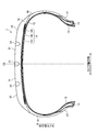
- FIG. 1 is a sectional view in the tire meridian direction showing a pneumatic tire according to an embodiment of the present invention.
- FIG. 2 is a tread plan view showing the pneumatic tire depicted in FIG. 1.
- FIG. 3 is a plan view showing a block of the pneumatic tire depicted in FIG. 1.
- FIG. 4 is an explanatory view showing an auxiliary sipe of the block shown in FIG.
- FIG. 5 is an explanatory diagram showing the operation of the pneumatic tire depicted in FIG. 1.
- FIG. 6 is an explanatory diagram illustrating an example of a three-dimensional sipe.
- FIG. 7 is an explanatory diagram illustrating an example of a three-dimensional sipe.
- FIG. 8 is an explanatory view showing a modified example of the pneumatic tire shown in FIG. 1.
- FIG. 9 is an explanatory view illustrating a modified example of the pneumatic tire depicted in FIG. 1.
- FIG. 10 is an explanatory view showing a modified example of the pneumatic tire shown in FIG. 1.
- FIG. 11 is an explanatory view showing a modified example of the pneumatic tire shown in FIG. 1.
- FIG. 12 is an explanatory diagram illustrating a modification of the pneumatic tire depicted in FIG. 1.
- FIG. 13 is an explanatory view illustrating a modified example of the pneumatic tire depicted in FIG. 1.
- FIG. 14 is an explanatory view showing a modified example of the pneumatic tire depicted in FIG. 1.
- FIG. 15 is an explanatory view showing a modified example of the pneumatic tire shown in FIG. 1.
- FIG. 10 is an explanatory view showing a modified example of the pneumatic tire shown in FIG. 1.
- FIG. 11 is an explanatory view showing a modified example of the pneumatic tire shown in FIG. 1.
- FIG. 12 is an explanatory diagram
- FIG. 16 is an explanatory diagram illustrating a modification of the pneumatic tire depicted in FIG. 1.
- FIG. 17 is an explanatory diagram illustrating a modification of the pneumatic tire depicted in FIG. 1.
- FIG. 18 is an explanatory diagram showing a modification of the pneumatic tire depicted in FIG.
- FIG. 19 is a tread plan view showing a modified example of the pneumatic tire depicted in FIG. 1.
- FIG. 20 is a chart showing the results of the performance test of the pneumatic tire according to the embodiment of the present invention.
- FIG. 1 is a sectional view in the tire meridian direction showing a pneumatic tire according to an embodiment of the present invention.
- the figure shows a radial tire for a passenger car as an example of the pneumatic tire 1.
- Reference sign CL is a tire equator plane.
- the pneumatic tire 1 includes a pair of bead cores 11, 11, a pair of bead fillers 12, 12, a carcass layer 13, a belt layer 14, a tread rubber 15, a pair of sidewall rubbers 16, 16, and a pair. Rim cushion rubbers 17 and 17 (see FIG. 1).
- the pair of bead cores 11 and 11 has an annular structure and constitutes the core of the left and right bead portions.
- the pair of bead fillers 12 and 12 are disposed on the outer periphery in the tire radial direction of the pair of bead cores 11 and 11 to reinforce the bead portion.
- the carcass layer 13 has a single-layer structure and is bridged in a toroidal shape between the left and right bead cores 11 and 11 to constitute a tire skeleton. Further, both end portions of the carcass layer 13 are wound and locked outward in the tire width direction so as to wrap the bead core 11 and the bead filler 12.
- the carcass layer 13 is formed by rolling a plurality of carcass cords made of steel or an organic fiber material (for example, aramid, nylon, polyester, rayon, etc.) with a coat rubber and having an absolute value of 85 [deg].
- a carcass angle of 95 [deg] or less inclination angle in the fiber direction of the carcass cord with respect to the tire circumferential direction).
- the belt layer 14 is formed by laminating a pair of cross belts 141 and 142 and a belt cover 143, and is arranged around the outer periphery of the carcass layer 13.
- the pair of cross belts 141 and 142 is formed by rolling a plurality of belt cords made of steel or organic fiber material with a coating rubber, and having a belt angle of 10 [deg] or more and 30 [deg] or less in absolute value.
- the pair of cross belts 141 and 142 have belt angles with different signs from each other (inclination angle of the fiber direction of the belt cord with respect to the tire circumferential direction), and are laminated so that the fiber directions of the belt cords cross each other. (Cross ply structure).
- the belt cover 143 is formed by rolling a plurality of belt cords made of steel or organic fiber material with a coat rubber, and has a belt angle of 10 [deg] or more and 45 [deg] or less in absolute value. Further, the belt cover 143 is disposed so as to be laminated on the outer side in the tire radial direction of the cross belts 141 and 142.
- the tread rubber 15 is disposed on the outer circumference in the tire radial direction of the carcass layer 13 and the belt layer 14 to constitute a tread portion of the tire.
- the pair of side wall rubbers 16 and 16 are respectively arranged on the outer side in the tire width direction of the carcass layer 13 to constitute left and right side wall portions.
- the pair of rim cushion rubbers 17, 17 are arranged on the outer sides in the tire width direction of the left and right bead cores 11, 11 and the bead fillers 12, 12 to constitute left and right bead portions.
- FIG. 2 is a tread plan view showing the pneumatic tire shown in FIG.
- FIG. 1 shows a pneumatic tire 1 having a general block pattern.
- Reference symbol T represents a tire ground contact end.
- the pneumatic tire 1 includes a plurality of circumferential main grooves 21 and 22 extending in the tire circumferential direction, a plurality of land portions 31 and 32 partitioned into the circumferential main grooves 21 and 22, and the land
- the tread portion includes a plurality of lug grooves 41 and 42 arranged in the portions 31 and 32 (see FIG. 2).
- the three circumferential main grooves 21 and 22 are arranged symmetrically about the tire equatorial plane CL.
- the circumferential main grooves 21 and 22 define two rows of center land portions 31 and 31 and a pair of left and right shoulder land portions 32 and 32.
- all the land portions 31 and 32 have a plurality of lug grooves 41 and 42 extending in the tire width direction, respectively.
- the lug grooves 41 and 42 have an open structure that crosses the land portions 31 and 32 in the tire width direction, and are arranged at predetermined intervals in the tire circumferential direction. Thereby, all the land parts 31 and 32 become the block row
- the circumferential main groove means a circumferential groove having a groove width of 4.0 [mm] or more.
- the lug groove mentioned later means the horizontal groove which has a groove width of 3.0 [mm] or more. These groove widths are measured excluding notches and chamfers formed in the groove openings.
- the sipe described later is a cut formed in the land portion, and generally has a sipe width of less than 1.0 [mm].
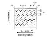
- FIG. 3 is a plan view showing a block of the pneumatic tire depicted in FIG. 1.
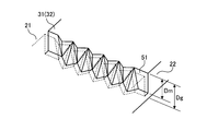
- FIG. 4 is an explanatory view showing an auxiliary sipe of the block shown in FIG. In these drawings, FIG. 3 shows a single block, and FIG. 4 shows a tread plan view of one auxiliary sipe 52 (FIG. 4A) and a plan view of a sipe wall surface of the auxiliary sipe 52 (FIG. b)).
- the land portions 31 and 32 are provided with a plurality of sipes 51 and 52, respectively, arranged in parallel at a predetermined interval from each other (see FIG. 2). These sipes 51 and 52 are classified into main sipes 51 and auxiliary sipes 52.
- the main sipe 51 is a general sipe that is widely used.
- the main sipe 51 may have either a straight shape or a bent shape in plan view of the tread portion.
- the main sipe 51 may have any of an open structure that penetrates the land portions 31 and 32, a closed structure that terminates in the land portions 31 and 32, and a semi-closed structure. Further, the main sipe 51 may have a bottom upper portion that raises the sipe depth.
- the main sipe 51 may be either a two-dimensional sipe or a three-dimensional sipe.
- the two-dimensional sipe is a sipe having a linear sipe wall surface in a cross-sectional view perpendicular to the sipe length direction (so-called plane sipe).
- the three-dimensional sipe is a sipe (so-called three-dimensional sipe) having a sipe wall surface that is bent in the sipe width direction in a cross-sectional view perpendicular to the sipe length direction.
- the three-dimensional sipe has an action of reinforcing the rigidity of the land portion because the meshing force of the opposing sipe wall surfaces is stronger than that of the two-dimensional sipe.
- the groove depth Dg of the circumferential main grooves 21 and 22 and the sipe depth Dm of the main sipe 51 have a relationship of 0.6 ⁇ Dm / Dg ⁇ 1.2 (FIGS. 6 and 7 described later). reference).
- the groove depth Dg of the circumferential main grooves 21 and 22 is measured at the maximum depth position of the circumferential main grooves 21 and 22. Therefore, when the circumferential main grooves 21 and 22 have bottom tops, these bottom tops are excluded and measured.
- the sipe depth Dm of the main sipe 51 is measured at the maximum depth position of the main sipe 51. Therefore, when the main sipe 51 has bottom tops, these bottom tops are excluded and measured.
- the sipe length Lm of the main sipe 51 when the tire is new and the sipe length Lm ′ of the main sipe 51 when the tire is worn 50% have a relationship of 0.7 ⁇ Lm ′ / Lm.
- the sipe length is measured as the length of the sipe when the sipe has a bent shape in plan view.
- the auxiliary sipe 52 has a bent shape in plan view of the tread portion (see FIG. 4).
- the bent shape includes, for example, a zigzag shape that extends while being refracted, and a wavy shape that extends while being bent.
- the auxiliary sipe 52 may have any of an open structure that penetrates the land portions 31 and 32, a closed structure that terminates in the land portions 31 and 32, and a semi-closed structure. Further, the auxiliary sipe 52 may be either a two-dimensional sipe or a three-dimensional sipe.
- the auxiliary sipe 52 is configured by connecting the first bent portion 521 and the second bent portion 522.
- the first bent portion 521 refers to a sipe portion having a predetermined sipe depth Ds_1 defined on the basis of the groove depth Dg of the circumferential main grooves 21 and 22 or the sipe depth Dm of the main sipe 51.
- the second bent portion 522 refers to a sipe portion having a sipe depth Ds_2 that is shallower than the first bent portion 521.
- the groove depth Dg of the circumferential main grooves 21 and 22, the sipe depth Ds_1 of the first bent portion 521 of the auxiliary sipe 52, and the sipe depth Ds_2 of the second bent portion 522 are 0.5.
- ⁇ Ds_1 / Dg 1.0 and 0.2 ⁇ Ds_2 / Ds_1 ⁇ 0.5.
- the auxiliary sipe 52 is configured by connecting a plurality of first bent portions 521 and a plurality of second bent portions 522 in a sipe length direction in a predetermined arrangement pattern. At this time, the total sipe length Ls_1 of the first bent portion 521 and the total sipe length Ls_2 of the second bent portion 522 in one auxiliary sipe 52 satisfy 0.25 ⁇ Ls_2 / (Ls_1 + Ls_2) ⁇ 0.75. Have a relationship. The total sipe length Ls_2 / (Ls_1 + Ls_2) is measured as the sipe length on the treads of the land portions 31 and 32.
- one block 311 includes a plurality of main sipes 51 and a plurality of auxiliary sipes 52.
- Each main sipe 51 has a zigzag shape and extends in the tire width direction and in the same direction.
- the main sipes 51 are arranged in parallel to each other with a predetermined interval in the tire circumferential direction.
- the sipe depth Dm of the main sipe 51 is set in a range of 6 [mm] ⁇ Dm ⁇ 8 [mm].
- the auxiliary sipe 52 is a two-dimensional sipe having a zigzag shape (see FIG. 4), and is arranged in parallel with a predetermined interval from the main sipe 51. Further, one auxiliary sipe 52 is disposed between the adjacent main sipes 51, 51. Thereby, the main sipes 51 and the auxiliary sipes 52 are alternately arranged adjacent to each other in the tire circumferential direction.
- the first bent portion 521 of the auxiliary sipe 52 is arranged with the extending direction aligned. Specifically, the first bent portion 521 of the auxiliary sipe 52 is inclined in one direction with respect to the tire circumferential direction, and the second bent portion 522 is in the other direction with respect to the tire circumferential direction (inclination direction of the first bent portion 521). The first bent portion 521 and the second bent portion 522 are inclined in different directions at a predetermined angle. And the 1st bending part 521 and the 2nd bending part 522 are connected alternately, and the zigzag shape of the auxiliary sipe 52 is comprised. Further, as shown in FIG. 4B, the first bent portion 521 having a deep sipe depth Ds_1 and the second bent portion 522 having a shallow sipe depth Ds_2 are alternately connected to form a comb-like auxiliary. A sipe 52 is formed.
- the sipe depth Ds_1 of the first bent portion 521 is set within the range of 0.60 ⁇ Ds_1 / Dm ⁇ 1.20 with respect to the sipe depth Dm of the main sipe 51.
- the sipe depth Ds_2 of the second bent portion 522 is shallower than the sipe depth Ds_1 of the first bent portion 521, and is set within a range of 0.2 [mm] ⁇ Ds_2 ⁇ 2.0 [mm]. Yes.
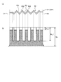
- FIG. 5 is an explanatory view showing the action of the pneumatic tire shown in FIG. In the figure, (a) shows the state of the tread surface of the block 311 (321) when the tire is new, and (b) shows the state of the tread surface of the block 311 (321) when 50 [%] wear.
- the block 311 (321) When the tire is new (see FIG. 5A), the block 311 (321) has the auxiliary sipe 52, so that the sipe has a higher density arrangement than the configuration in which the block has only the main sipe (not shown).
- the edge component of the block 311 (321) increases. Thereby, the traction property is improved, and the snow maneuvering performance of the tire is improved.
- the auxiliary sipe 52 since the auxiliary sipe 52 includes the first bent portion 521 having a deep sipe depth Ds_1 (see FIG. 4), the auxiliary sipe 52 has a block having a uniform shallow depth (not shown). The water absorption of 311 (321) is improved. Thereby, the braking performance on ice of a tire improves.
- the auxiliary sipe 52 includes the second bent portion 522 having the shallow sipe depth Ds_2, the second bent portion 522 functions as the bottom upper portion of the auxiliary sipe 52. Accordingly, the rigidity of the block 311 (321) is appropriately ensured and the performance on the snow on the tire is improved as compared with a configuration (not shown) in which the auxiliary sipe has a uniform deep sipe depth.
- the auxiliary sipe 52 has a comb-like shape formed by alternately connecting the first bent portion 521 having the deep sipe depth Ds_1 and the second bent portion 522 having the shallow sipe depth Ds_2, so that the auxiliary sipe 52
- the improvement in water absorption of the block 311 (321) by 52 and the securing of rigidity can be appropriately achieved. These improve the snow handling performance and on-ice braking performance of the tire when the tire is new.
- the shallow second bent portion 522 disappears due to wear of the block 311 (321), and the first bent portion 521 of the main sipe 51 and the auxiliary sipe 52 Remains on the tread of the block 311 (321).
- the edge component of the block 311 (321) in the middle period of wear increases compared to a configuration in which the block has only the main sipes (not shown). Thereby, the traction property is improved, and the snow maneuvering performance of the tire is improved.
- first bent portion 521 of the auxiliary sipe 52 is arranged with the extending direction aligned (see FIG. 4A), when the second bent portion 522 disappears due to wear of the block 311 (321), Only the first bent portion 521 extending in one direction remains on the tread surface of the block 311 (321) (see FIG. 5B). Thereby, the edge component of the block 311 (321) with respect to a specific direction (extending direction of the 1st bending part 521) is ensured. Thereby, the snow maneuvering performance of a tire improves efficiently.
- the main sipe 51 is preferably a three-dimensional sipe having a bent shape in plan view of the tread portion.
- the three-dimensional sipe include the following (see FIGS. 6 and 7).
- 6 and 7 are explanatory diagrams showing an example of a three-dimensional sipe. These figures show the sipe wall surface of the three-dimensional sipe.
- the sipe wall surface has a structure in which a triangular pyramid and an inverted triangular pyramid are connected in the sipe length direction.
- the sipe wall surface has a zigzag shape on the tread surface side and a zigzag shape on the bottom side that are shifted in pitch in the tire width direction, and unevenness that faces each other between the zigzag shapes on the tread surface side and the bottom side.
- the sipe wall surface is an unevenness when viewed in the tire rotation direction among these unevennesses, between the convex bending point on the tread surface side and the concave bending point on the bottom side, the concave bending point on the tread surface side and the bottom side Between the convex bend points of the tread surface and the convex bend points on the tread surface side, and adjacent convex bend points that are adjacent to each other with ridge lines, and the ridge lines between the ridge lines in order in the tire width direction. It is formed by connecting in a plane.
- one sipe wall surface has an uneven surface in which convex triangular pyramids and inverted triangular pyramids are arranged alternately in the tire width direction, and the other sipe wall surface alternates between concave triangular pyramids and inverted triangular pyramids.
- the sipe wall surface has the uneven
- the sipe wall surface has a structure in which a plurality of rectangular columns having a block shape are connected in the sipe depth direction and the sipe length direction while being inclined with respect to the sipe depth direction.
- the sipe wall surface has a zigzag shape on the tread surface.
- the sipe wall surface has a bent portion that is bent in the tire circumferential direction at two or more locations in the tire radial direction inside the block and continues in the tire width direction, and has an amplitude in the tire radial direction at the bent portion. It has a zigzag shape.
- the sipe wall surface makes the tire circumferential amplitude constant
- the inclination angle in the tire circumferential direction with respect to the normal direction of the tread surface is made smaller at the sipe bottom side part than the tread surface side part and bent.
- the amplitude of the tire in the tire radial direction is made larger at the sipe bottom side than at the tread surface side.
- [Modification] 8 and 9 are explanatory views showing a modification of the pneumatic tire shown in FIG. These drawings show plan views of a single block 311 (321) when the tire is new.
- main sipes 51 and auxiliary sipes 52 are alternately arranged in the tire circumferential direction in one block 311 (321).
- one auxiliary sipe 52 is disposed between the adjacent main sipes 51, 51.
- the arrangement balance between the main sipe 51 and the first bent portion 521 of the auxiliary sipe 52 is optimized in the middle period of wear, which is preferable in that the snow handling performance and on-ice braking performance of the tire can be effectively improved. .
- the present invention is not limited to this, and the arrangement pattern of the plurality of main sipes 51 and the plurality of auxiliary sipes 52 can be arbitrarily selected.
- a part of the main sipes 51 is continuously arranged by leaving a portion without the auxiliary sipes 52 between the adjacent main sipes 51, 51. That is, in the configuration of FIG. 3, some of the auxiliary sipes 52 are thinned out. Thereby, the auxiliary sipe 52 can be disposed only in a suitable region of the block 311 (321).
- two auxiliary sipes 52 are arranged between adjacent main sipes 51, 51.
- a plurality of auxiliary sipes 52 may be arranged between the adjacent main sipes 51, 51. Accordingly, the sipe density of the block 311 (321) can be increased while securing the rigidity of the block 311 (321) by the second bent portion 522 of the auxiliary sipe 52.
- the number of auxiliary sipes 52 arranged between adjacent main sipes 51 and 51 is three or less.
- the number Nm of main sipes 51 and the number Ns of auxiliary sipes 52 arranged in one block 311 (321) are 0.30 ⁇ Ns / (Nm + Ns) ⁇ 0. .60 relationship is preferred.
- FIG. 10 to 13 are explanatory views showing modifications of the pneumatic tire shown in FIG. These drawings show a state in which the second bent portion 522 disappears due to wear of the block 311 (321) in the middle stage of wear (at the time of 50% wear).
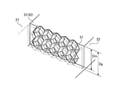
- the auxiliary sipe 52 has a zigzag shape continuous in the tire width direction as shown in FIG.
- the first bent portions 521 of all the auxiliary sipes 52 arranged in one block 311 (321) extend in one direction, and all the second bent portions 522 extend in the other direction.
- the first bent portion 521 and the second bent portion 522 extend in different directions at a predetermined angle.
- the auxiliary sipe 52 has a bent shape, and is alternately connected at the bent point of the bent shape with the first bent portion 521 having a deep sipe depth Ds_1 and the second bent portion 522 having a shallow sipe depth Ds_2.
- the auxiliary sipes 52 are configured.
- the first bent portion 521 and the second bent portion 522 of the adjacent auxiliary sipes 52 are extended by the plurality of auxiliary sipes 52 arranged in one block 311 (321). The directions are different from each other.
- Such a configuration is preferable in that the edge component of the first bent portion 521 can be dispersed and remain when the second bent portion 522 disappears in the middle stage of wear.
- the relationship between the extending direction of the first bent portion 521 and the extending direction of the second bent portion 522 in one auxiliary sipe 52 can be arbitrarily set. As shown in FIGS. 12 and 13, a plurality of first bent portions 521 extending in different directions may be connected to each other in one auxiliary sipe 52.
- the auxiliary sipe 52 alternately includes one first bent portion 521 inclined only in a predetermined direction and three second bent portions 522 (not shown) inclined in different directions. Connected and configured. For this reason, when the second bent portion 522 disappears in the middle stage of wear, the first bent portion 521 remains in a smaller number than the configuration of FIG.
- the auxiliary sipe 52 alternately includes two first bent portions 521 inclined in different directions and two second bent portions 522 (not shown) inclined in different directions. Connected to and configured. For this reason, when the second bent portion 522 disappears in the middle stage of wear, the V-shaped first bent portion 521 remains.
- the auxiliary sipe 52 alternately includes three first bent portions 521 inclined in different directions and one second bent portion 522 (not shown) inclined in different directions. Connected to and configured. For this reason, when the second bent portion 522 disappears in the middle stage of wear, the Z-shaped first bent portion 521 remains.
- FIG. 14 and 15 are explanatory views showing a modification of the pneumatic tire shown in FIG. These drawings show plan views of a single block 311 (321) when the tire is new.
- the main sipe 51 and the auxiliary sipe 52 are arranged in parallel with each other at a predetermined interval in one block 311 (321).
- a plurality of main sipes 51 are arranged in parallel, and an auxiliary sipe 52 is an extension of these main sipes 51. You may arrange
- one auxiliary sipe 52 is arranged in the center region in the tire width direction of the block 311 (321) and extends in the tire circumferential direction.
- a plurality of main sipes 51 are arranged in the left and right regions of the block 311 (321) with the auxiliary sipe 52 as a boundary, and are arranged in parallel to each other and extend in the tire width direction.
- Each main sipe 51 extends in a direction substantially orthogonal to the auxiliary sipe 52 and terminates in front of the auxiliary sipe 52.
- one auxiliary sipe 52 is disposed in the central region of the block 311 (321) and extends while inclining at a predetermined inclination angle with respect to the tire circumferential direction.
- a plurality of main sipes 51 are arranged in each region of the block 311 (321) with the auxiliary sipe 52 as a boundary, and are arranged in parallel to each other and extend in the tire width direction.
- Each main sipe 51 is inclined at an inclination angle of about 45 [deg] with respect to the auxiliary sipe 52 and ends before the auxiliary sipe 52.
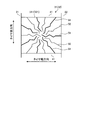
- FIG. 16 to 18 are explanatory views showing modifications of the pneumatic tire shown in FIG. This figure shows a plan view of a single block 311 (321) when the tire is new.
- a plurality of main sipes 51 and a plurality of auxiliary sipes 52 extend radially from the center of the block 311 (321) toward the edge. For this reason, the sipes 51 and 52 are densely arranged at the center of the block 311 (321), and the sipes 51 and 52 are sparsely arranged at the edge of the block 311 (321). Further, the main sipes 51 and the auxiliary sipes 52 are alternately arranged in the circumferential direction of the block 311 (321) without crossing each other. At this time, a plurality of auxiliary sipes 52 may be arranged between the adjacent main sipes 51, 51 (not shown, see FIG. 9).
- one auxiliary sipe 52 is inclined in the direction in which the center of the block 311 (321) is inclined at approximately 45 [deg] with respect to the tire width direction (FIG. 17) or the tire circumferential direction. It is extended.
- a plurality of main sipes 51 are arranged in each area of the block 311 (321) with the auxiliary sipes 52 as boundaries. Each main sipe 51 extends radially from the center of the block 311 (321) toward the edge. Further, the main sipe 51 and the auxiliary sipe 52 do not cross each other.
- one end of the main sipe 51 and the auxiliary sipe 52 is open at the edge of the block 311 (321) in the tire circumferential direction and the tire width direction.
- the present invention is not limited thereto, and both ends of the main sipe 51 and the auxiliary sipe 52 may be terminated in the block 311 (321) (not shown).
- FIG. 19 is a tread plan view showing a modification of the pneumatic tire shown in FIG. The figure shows a tread pattern of a passenger car winter tire.
- the pneumatic tire 1 includes three circumferential main grooves 21 and 22 having a straight shape, and a plurality of lug grooves 41 and 42 that open in the circumferential main grooves 21 and 22.
- the circumferential main grooves 21 and 22 and the lug grooves 41 and 42 are divided into a plurality of blocks 321 and 322. Accordingly, the land portions 31 and 32 are block rows.
- Each of the blocks 321 and 322 includes a plurality of main sipes 51 and a plurality of auxiliary sipes 52, respectively.
- the present invention is not limited thereto, and the main sipe 51 and the auxiliary sipe 52 may be disposed on the rib-shaped land portions 31 and 32 (see FIG. 19).
- the pneumatic tire 1 includes two circumferential main grooves 22, 22 that extend in the tire circumferential direction while stepping back in a progressive manner, and these circumferential main grooves 22, 22.
- a center land portion 31 and left and right shoulder land portions 32, 32 are provided.
- the center land portion 31 is a rib continuous in the tire circumferential direction, and has a plurality of cutout grooves 312 that open to one circumferential main groove 22.
- the center land portion 31 is partitioned by left and right circumferential main grooves 22 and 22 having an indented shape, and has a shape in which a V-shape is continuously provided in the tire circumferential direction.
- left and right shoulder land portions 32, 32 have a plurality of inclined lug grooves 42 that are inclined with respect to the tire circumferential direction, and are divided into a plurality of blocks 321 by these inclined lug grooves 42. . Further, some of the blocks 321 have a notch groove 322 that is open in the lug groove 42 while being inclined in the tire circumferential direction.
- the center land portion 31 has a plurality of main sipes 51 and a plurality of auxiliary sipes 52.
- the main sipes 51 and the auxiliary sipes 52 are alternately arranged in the tire circumferential direction with a predetermined interval therebetween, and extend in the tire width direction.
- the main sipe 51 and the auxiliary sipe 52 are also arranged on the V-shaped branch portion of the center land portion 31.
- the shoulder land portion 32 has a plurality of main sipes 51 and a plurality of auxiliary sipes 52.
- the main sipes 51 and the auxiliary sipes 52 are arranged alternately and in parallel along the inclination direction of the inclined lug groove 42. Further, the main sipe 51 and the auxiliary sipe 52 extend while inclining at a predetermined angle in the tire circumferential direction, and open to the inclined lug grooves 42 and 42 adjacent to each other in the tire circumferential direction.
- the center land portion 31 has a shape in which V-shapes are continuously arranged in the tire circumferential direction, so that an edge component is increased and traction is improved. Moreover, the rigidity of the center land part 31 is ensured because the center land part 31 has a rib-like structure. These improve the snow handling performance of the tire.
- the pneumatic tire 1 includes a plurality of circumferential main grooves 21 and 22 extending in the tire circumferential direction, and a plurality of land portions 31 that are partitioned by the circumferential main grooves 21 and 22. , 32 (see FIG. 2). Further, the land portions 31 and 32 include a plurality of auxiliary sipes 52 (see FIG. 3). Further, the auxiliary sipe 52 has a bent shape formed by connecting the first bent portion 521 and the second bent portion 522 in a plan view of the tread portion (see FIG. 4A).
- the groove depth Dg of the circumferential main grooves 21 and 22, the sipe depth Ds_1 of the first bent portion 521 of the auxiliary sipe 52, and the sipe depth Ds_2 of the second bent portion 522 are 0.5 ⁇ Ds_1 /.
- the auxiliary sipe 52 when the tire is new (see FIG. 5A), the auxiliary sipe 52 includes the first bent portion 521 having a deep sipe depth Ds_1 (see FIGS. 3 and 4B). The water absorption of the part (blocks 311 and 321) is improved. Thereby, there exists an advantage which the braking performance on ice of a tire improves. Further, since the auxiliary sipe 52 includes the second bent portion 522 having a shallow sipe depth Ds_2, there is an advantage that the rigidity of the land portion is appropriately secured and the on-snow performance of the tire is improved.
- the total sipe length Ls_1 of the first bent portion 521 and the total sipe length Ls_2 of the second bent portion 522 in one auxiliary sipe 52 are 0.25 ⁇ Ls_2 / (Ls_1 + Ls_2). ⁇ 0.75 (see FIG. 4).
- ratio Ls_2 / (Ls_1 + Ls_2) of the 2nd bending part 522 in the auxiliary sipe 52 is optimized. That is, by satisfying 0.25 ⁇ Ls_2 / (Ls_1 + Ls_2), the ratio of the second bent portion 522 is secured, and the rigidity of the land portion is secured.
- Ls_2 / (Ls_1 + Ls_2) ⁇ 0.75, the ratio of the 1st bending part 521 is ensured and the water absorption of a land part improves.
- the first bent portion 521 in one auxiliary sipe 52 is arranged with the extending direction aligned (see FIG. 4).
- the second bent portion 522 disappears in the middle stage of wear
- the first bent portion 521 is arranged with the extending direction aligned, so that an edge component in a specific direction is ensured.
- the land portions 31 and 32 include a plurality of main sipes 51 (see FIGS. 2 and 3). Further, the sipe depth Dm of the main sipe 51 and the sipe depth Ds_1 of the first bent portion 521 of the auxiliary sipe 52 have a relationship of 0.60 ⁇ Ds_1 / Dm ⁇ 1.20 (see FIG. 4). Thereby, there exists an advantage by which the sipe depth Ds_1 of the 1st bending part 521 is optimized.
- the main sipe 51 and the auxiliary sipe 52 are arranged in parallel with each other (see FIG. 3). Thereby, there exists an advantage which can raise the edge component of the land part with respect to the sequence direction of the sipe 51,52.
- the number of auxiliary sipes 52 disposed between a pair of adjacent main sipes 51, 51 is three or less (see FIGS. 3, 8, and 9).
- the number Nm of main sipes 51 arranged in one land portion 31, 32 and the number Ns of auxiliary sipes 52 are 0.30 ⁇ Ns / (Nm + Ns) ⁇ 0.60. (See FIGS. 3, 8, and 9). Thereby, there exists an advantage which can suppress the rigidity fall of the land part by the excessive arrangement
- the groove depth Dg of the circumferential main grooves 21 and 22 and the sipe depth Dm of the main sipe 51 have a relationship of 0.6 ⁇ Dm / Dg ⁇ 1.2 ( (See FIG. 6).
- the sipe depth Dm of the main sipe 51 is optimized.
- the sipe length Lm of the main sipe 51 when the tire is new and the sipe length Lm ′ of the main sipe 51 when 50% is worn are 0.7 ⁇ Lm ′ / Lm. It is. Thereby, there exists an advantage which the main sipe 51 remains appropriately until the middle wear of a tire.
- the main sipe 51 is a three-dimensional sipe (see FIGS. 6 and 7) having a bent shape in a plan view of the tread portion
- the auxiliary sipe 52 is a two-dimensional sipe (See FIG. 4).
- the main sipe 51 is a three-dimensional sipe
- the rigidity of the land portion is increased, and the snow handling performance of the tire is improved.
- the auxiliary sipe 52 is a two-dimensional sipe, the auxiliary sipe 52 can be easily disposed between the main sipes 51.
- the mixed arrangement of the main sipe 51 and the auxiliary sipe 52 is facilitated, and there is an advantage that the braking performance on ice and the manipulation performance on snow are improved.
- the main sipe 51 and the auxiliary sipe 52 have a bent shape (see FIG. 3)
- it is particularly beneficial that the mixed arrangement of the main sipe 51 and the auxiliary sipe 52 can be facilitated.
- the plurality of main sipes 51 are arranged in parallel, and at least one auxiliary sipe 52 extends while being inclined at a predetermined angle with respect to the extending direction of the plurality of main sipes 51. (See FIG. 14 and FIG. 15).
- action of the block 311 (321) improves by arrange
- the land portions 31 and 32 have a plurality of blocks 321 and 322 (see FIG. 2).
- the plurality of main sipes 51 and at least one auxiliary sipe 52 extend radially from the center of the block 311 (321) toward the edge (see FIGS. 16 to 18).
- the sipe density at the center of the block 311 (321) becomes dense.
- the drainage performance of the block 311 (321) is improved, and the edge component of the block 311 (321) is increased, thereby improving the braking performance of the tire on ice.
- the sipe density at the edge of the block 311 (321) becomes sparse. Thereby, the rigidity in the edge part of the block 311 (321) is ensured, and there exists an advantage which the on-snow operation performance of a tire improves.
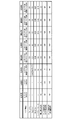
- FIG. 20 is a chart showing the results of the performance test of the pneumatic tire according to the embodiment of the present invention.
- test vehicle runs on the snow road surface of the snow road test site, and a specialized test driver performs a feeling evaluation on the lane change performance and cornering performance.
- This evaluation is performed by index evaluation using Conventional Example 1 as a reference (100), and the larger the value, the better.
- the pneumatic tire 1 of Examples 1 to 3 has the structure described in FIGS.
- One block 311 (321) has seven main sipes 51 and eight auxiliary sipes 52.
- the main sipes 51 and the auxiliary sipes 52 are arranged in parallel and alternately.
- the main sipe 51 is a three-dimensional sipe having a zigzag shape and does not have a bottom upper part.
- the auxiliary sipe 52 is a two-dimensional sipe having a zigzag shape and has the structure shown in FIG.
- the pneumatic tire of Conventional Example 1 has only the main sipe 51 and does not have the auxiliary sipe 52 in the pneumatic tire of the example. Further, in the pneumatic tire of Conventional Example 2, the sipe 51, 52 in the pneumatic tire of the example is the main sipe 51.
- the pneumatic tire of Conventional Example 3 is a shallow sipe in which the auxiliary sipe 52 has a constant sipe depth (1.0 [mm]) in the pneumatic tire of the example.
Landscapes
- Engineering & Computer Science (AREA)
- Mechanical Engineering (AREA)
- Tires In General (AREA)
Abstract
Description
図1は、この発明の実施の形態にかかる空気入りタイヤを示すタイヤ子午線方向の断面図である。同図は、空気入りタイヤ1の一例として、乗用車用ラジアルタイヤを示している。なお、符号CLは、タイヤ赤道面である。
図3は、図1に記載した空気入りタイヤのブロックを示す平面図である。図4は、図3に記載したブロックの補助サイプを示す説明図である。これらの図において、図3は、単体のブロックを示し、図4は、1本の補助サイプ52のトレッド平面図(図4(a))および補助サイプ52のサイプ壁面の平面図(図4(b))を示している。
図8および図9は、図1に記載した空気入りタイヤの変形例を示す説明図である。これらの図は、タイヤ新品時における単体のブロック311(321)の平面図を示している。
以上説明したように、この空気入りタイヤ1は、タイヤ周方向に延在する複数の周方向主溝21、22と、これらの周方向主溝21、22に区画されて成る複数の陸部31、32とを備える(図2参照)。また、陸部31、32が、複数の補助サイプ52を備える(図3参照)。また、補助サイプ52が、トレッド部の平面視にて、第一屈曲部521と第二屈曲部522とを接続して成る屈曲形状を有する(図4(a)参照)。また、周方向主溝21、22の溝深さDgと、補助サイプ52の第一屈曲部521のサイプ深さDs_1および第二屈曲部522のサイプ深さDs_2とが、0.5≦Ds_1/Dg≦1.0および0.2≦Ds_2/Ds_1≦0.5の関係を有する(図4(b)参照)。
Claims (12)
- タイヤ周方向に延在する複数の周方向主溝と、前記周方向主溝に区画されて成る複数の陸部とを備える空気入りタイヤであって、
前記陸部が、複数の補助サイプを備え、
前記補助サイプが、トレッド部の平面視にて、第一屈曲部と第二屈曲部とを接続して成る屈曲形状を有し、且つ、
前記周方向主溝の溝深さDgと、前記補助サイプの前記第一屈曲部のサイプ深さDs_1および前記第二屈曲部のサイプ深さDs_2とが、0.5≦Ds_1/Dg≦1.0および0.2≦Ds_2/Ds_1≦0.5の関係を有することを特徴とする空気入りタイヤ。 - 1つの前記補助サイプにおける前記第一屈曲部の総サイプ長さLs_1と前記第二屈曲部の総サイプ長さLs_2とが、0.25≦Ls_2/(Ls_1+Ls_2)≦0.75の関係を有する請求項1に記載の空気入りタイヤ。
- 1つの前記補助サイプにおける前記第一屈曲部が延在方向を揃えて配置される請求項1または2に記載の空気入りタイヤ。
- 前記陸部が、複数の主サイプを備え、且つ、
前記主サイプのサイプ深さDmと、前記第一屈曲部のサイプ深さDs_1とが、0.60≦Ds_1/Dm≦1.20の関係を有する請求項1~3のいずれか一つに記載の空気入りタイヤ。 - 前記主サイプと前記補助サイプとが、相互に並列に配置される請求項4に記載の空気入りタイヤ。
- 隣り合う一対の前記主サイプの間に配置される前記補助サイプの数が、3つ以下である請求項5に記載の空気入りタイヤ。
- 1つの前記陸部に配置された前記主サイプの数Nmと、前記補助サイプの数Nsとが、0.30≦Ns/(Nm+Ns)≦0.60の関係を有する請求項1~6のいずれか一つに記載の空気入りタイヤ。
- 前記周方向主溝の溝深さDgと、前記主サイプのサイプ深さDmとが、0.6≦Dm/Dg≦1.2の関係を有する請求項1~7のいずれか一つに記載の空気入りタイヤ。
- タイヤ新品時における前記主サイプのサイプ長さLmと、50[%]摩耗時における前記主サイプのサイプ長さLm’とが、0.7≦Lm’/Lmである請求項1~8のいずれか一つに記載の空気入りタイヤ。
- 前記主サイプが、トレッド部の平面視にて屈曲形状を有する三次元サイプであり、前記補助サイプが、二次元サイプである請求項4~9のいずれか一つに記載の空気入りタイヤ。
- 複数の前記主サイプが並列に配置されると共に、少なくとも1本の前記補助サイプが複数の前記主サイプの延在方向に対して所定角度で傾斜しつつ延在する請求項1~3のいずれか一つに記載の空気入りタイヤ。
- 前記陸部が、複数のブロックを有し、複数の前記主サイプと少なくとも1本の前記補助サイプとが、前記ブロックの中心部から縁部に向かって放射状に延在する請求項1~3のいずれか一つに記載の空気入りタイヤ。
Priority Applications (4)
| Application Number | Priority Date | Filing Date | Title |
|---|---|---|---|
| US14/405,665 US20150151586A1 (en) | 2012-06-05 | 2013-06-05 | Pneumatic Tire |
| EP13800159.9A EP2857225A4 (en) | 2012-06-05 | 2013-06-05 | TIRE |
| RU2014152699/11A RU2585194C1 (ru) | 2012-06-05 | 2013-06-05 | Пневматическая шина |
| CN201380029441.8A CN104364091B (zh) | 2012-06-05 | 2013-06-05 | 充气轮胎 |
Applications Claiming Priority (2)
| Application Number | Priority Date | Filing Date | Title |
|---|---|---|---|
| JP2012128342A JP5835112B2 (ja) | 2012-06-05 | 2012-06-05 | 空気入りタイヤ |
| JP2012-128342 | 2012-06-05 |
Publications (1)
| Publication Number | Publication Date |
|---|---|
| WO2013183685A1 true WO2013183685A1 (ja) | 2013-12-12 |
Family
ID=49712074
Family Applications (1)
| Application Number | Title | Priority Date | Filing Date |
|---|---|---|---|
| PCT/JP2013/065625 WO2013183685A1 (ja) | 2012-06-05 | 2013-06-05 | 空気入りタイヤ |
Country Status (6)
| Country | Link |
|---|---|
| US (1) | US20150151586A1 (ja) |
| EP (1) | EP2857225A4 (ja) |
| JP (1) | JP5835112B2 (ja) |
| CN (1) | CN104364091B (ja) |
| RU (1) | RU2585194C1 (ja) |
| WO (1) | WO2013183685A1 (ja) |
Cited By (2)
| Publication number | Priority date | Publication date | Assignee | Title |
|---|---|---|---|---|
| US10179483B2 (en) | 2014-05-01 | 2019-01-15 | The Yokohama Rubber Co., Ltd. | Pneumatic tire |
| US10603961B2 (en) | 2014-10-07 | 2020-03-31 | The Yokohama Rubber Co., Ltd. | Pneumatic tire |
Families Citing this family (23)
| Publication number | Priority date | Publication date | Assignee | Title |
|---|---|---|---|---|
| NL2009980C2 (en) * | 2012-12-13 | 2014-06-16 | Ct Voor Tech Informatica B V | A method of producing glass products from glass product material and an assembly for performing said method. |
| JP6287299B2 (ja) * | 2014-02-12 | 2018-03-07 | 横浜ゴム株式会社 | 空気入りタイヤ |
| JP6329010B2 (ja) * | 2014-06-13 | 2018-05-23 | 株式会社ブリヂストン | 空気入りタイヤ |
| JP6393658B2 (ja) * | 2015-05-25 | 2018-09-19 | 株式会社ブリヂストン | 空気入りタイヤ |
| JP6482396B2 (ja) * | 2015-06-15 | 2019-03-13 | 株式会社ブリヂストン | 空気入りタイヤ |
| JP6825434B2 (ja) * | 2017-03-16 | 2021-02-03 | 住友ゴム工業株式会社 | タイヤ |
| CN109094302B (zh) * | 2017-06-20 | 2022-01-28 | 住友橡胶工业株式会社 | 充气轮胎 |
| DE102017211129A1 (de) * | 2017-06-30 | 2019-01-03 | Continental Reifen Deutschland Gmbh | Fahrzeugluftreifen |
| DE102017211128A1 (de) * | 2017-06-30 | 2019-01-03 | Continental Reifen Deutschland Gmbh | Fahrzeugluftreifen |
| CN111417526A (zh) * | 2017-11-30 | 2020-07-14 | 米其林企业总公司 | 持久性能轮胎的胎面 |
| DE102017221579A1 (de) * | 2017-11-30 | 2019-06-06 | Continental Reifen Deutschland Gmbh | Fahrzeugluftreifen |
| DE102017221582A1 (de) * | 2017-11-30 | 2019-06-06 | Continental Reifen Deutschland Gmbh | Fahrzeugluftreifen |
| JP7013878B2 (ja) * | 2018-01-11 | 2022-02-01 | 横浜ゴム株式会社 | 空気入りタイヤ |
| US20190381837A1 (en) * | 2018-06-13 | 2019-12-19 | The Goodyear Tire & Rubber Company | Multiplane interlocking structure for a tread of a tire |
| JP7115248B2 (ja) * | 2018-11-26 | 2022-08-09 | 横浜ゴム株式会社 | 空気入りタイヤ |
| JP6711441B1 (ja) * | 2019-06-19 | 2020-06-17 | 横浜ゴム株式会社 | 空気入りタイヤ |
| WO2020171235A1 (ja) * | 2019-02-22 | 2020-08-27 | 横浜ゴム株式会社 | 空気入りタイヤ |
| DE102019204326A1 (de) * | 2019-03-28 | 2020-10-01 | Continental Reifen Deutschland Gmbh | Fahrzeugluftreifen |
| DE102019204327A1 (de) * | 2019-03-28 | 2020-10-01 | Continental Reifen Deutschland Gmbh | Fahrzeugluftreifen |
| JP7293998B2 (ja) * | 2019-08-30 | 2023-06-20 | 横浜ゴム株式会社 | 空気入りタイヤ及びタイヤ成形用金型 |
| JP7357840B2 (ja) * | 2019-12-11 | 2023-10-10 | Toyo Tire株式会社 | タイヤ |
| JP7413774B2 (ja) | 2019-12-26 | 2024-01-16 | 住友ゴム工業株式会社 | タイヤ |
| US11691459B2 (en) * | 2020-03-06 | 2023-07-04 | Sumitomo Rubber Industries, Ltd. | Tire |
Citations (9)
| Publication number | Priority date | Publication date | Assignee | Title |
|---|---|---|---|---|
| JPH05330319A (ja) * | 1992-06-04 | 1993-12-14 | Bridgestone Corp | タイヤのブロック及び空気入りタイヤ |
| JPH10906A (ja) * | 1996-04-19 | 1998-01-06 | Bridgestone Corp | 空気入りタイヤ |
| JPH1178431A (ja) * | 1997-09-05 | 1999-03-23 | Yokohama Rubber Co Ltd:The | スタッドレスタイヤ |
| JP2002187413A (ja) * | 2000-12-21 | 2002-07-02 | Toyo Tire & Rubber Co Ltd | 空気入りタイヤ |
| JP2002192917A (ja) * | 2000-12-26 | 2002-07-10 | Toyo Tire & Rubber Co Ltd | 空気入りタイヤ |
| JP3894743B2 (ja) | 2001-04-05 | 2007-03-22 | 横浜ゴム株式会社 | 空気入りタイヤ |
| JP2009012648A (ja) | 2007-07-05 | 2009-01-22 | Bridgestone Corp | 空気入りラジアルタイヤ |
| JP4316452B2 (ja) | 2003-09-29 | 2009-08-19 | 横浜ゴム株式会社 | 空気入りタイヤ |
| JP4340112B2 (ja) | 2003-08-20 | 2009-10-07 | 住友ゴム工業株式会社 | 空気入りタイヤ |
Family Cites Families (19)
| Publication number | Priority date | Publication date | Assignee | Title |
|---|---|---|---|---|
| GB869980A (en) * | 1958-06-20 | 1961-06-07 | Us Rubber Co | Improvements in slotted tyre tread |
| US2938560A (en) * | 1958-12-31 | 1960-05-31 | Us Rubber Co | Tread construction and mold |
| US5647926A (en) * | 1995-12-12 | 1997-07-15 | The Goodyear Tire & Rubber Company | Winter automobile or light truck tire |
| JPH10151915A (ja) * | 1996-11-21 | 1998-06-09 | Sumitomo Rubber Ind Ltd | 空気入りタイヤ |
| JP3709256B2 (ja) * | 1997-05-08 | 2005-10-26 | 株式会社ブリヂストン | 空気入りタイヤ |
| JP2002273736A (ja) * | 2001-03-16 | 2002-09-25 | Ohtsu Tire & Rubber Co Ltd :The | タイヤ成形用金型及び空気入りタイヤ |
| JP4620276B2 (ja) * | 2001-03-26 | 2011-01-26 | 東洋ゴム工業株式会社 | 空気入りラジアルタイヤ |
| JP4726106B2 (ja) * | 2001-09-20 | 2011-07-20 | 東洋ゴム工業株式会社 | 空気入りタイヤ |
| JP2005041339A (ja) * | 2003-07-22 | 2005-02-17 | Yokohama Rubber Co Ltd:The | 空気入りタイヤ |
| JP4377649B2 (ja) * | 2003-10-15 | 2009-12-02 | 住友ゴム工業株式会社 | 空気入りタイヤ |
| JP2006007793A (ja) * | 2004-06-22 | 2006-01-12 | Bridgestone Corp | 空気入りタイヤ |
| JP4299745B2 (ja) * | 2004-08-12 | 2009-07-22 | 住友ゴム工業株式会社 | 空気入りタイヤ |
| WO2007088738A1 (ja) * | 2006-01-31 | 2007-08-09 | Bridgestone Corporation | 空気入りタイヤ |
| JP2009248819A (ja) * | 2008-04-08 | 2009-10-29 | Toyo Tire & Rubber Co Ltd | 空気入りタイヤ |
| DE102008029659A1 (de) * | 2008-06-24 | 2009-12-31 | Continental Aktiengesellschaft | Fahrzeugluftreifen |
| US20100005115A1 (en) * | 2008-07-03 | 2010-01-07 | Sap Ag | Method and system for generating documents usable by a plurality of differing computer applications |
| JP4548534B2 (ja) * | 2008-09-01 | 2010-09-22 | 横浜ゴム株式会社 | 空気入りタイヤ |
| JP2011079406A (ja) * | 2009-10-06 | 2011-04-21 | Yokohama Rubber Co Ltd:The | 空気入りタイヤ |
| JP5479935B2 (ja) * | 2010-02-08 | 2014-04-23 | 株式会社ブリヂストン | 空気入りタイヤ |
-
2012
- 2012-06-05 JP JP2012128342A patent/JP5835112B2/ja active Active
-
2013
- 2013-06-05 WO PCT/JP2013/065625 patent/WO2013183685A1/ja active Application Filing
- 2013-06-05 RU RU2014152699/11A patent/RU2585194C1/ru not_active IP Right Cessation
- 2013-06-05 CN CN201380029441.8A patent/CN104364091B/zh not_active Expired - Fee Related
- 2013-06-05 EP EP13800159.9A patent/EP2857225A4/en not_active Withdrawn
- 2013-06-05 US US14/405,665 patent/US20150151586A1/en not_active Abandoned
Patent Citations (9)
| Publication number | Priority date | Publication date | Assignee | Title |
|---|---|---|---|---|
| JPH05330319A (ja) * | 1992-06-04 | 1993-12-14 | Bridgestone Corp | タイヤのブロック及び空気入りタイヤ |
| JPH10906A (ja) * | 1996-04-19 | 1998-01-06 | Bridgestone Corp | 空気入りタイヤ |
| JPH1178431A (ja) * | 1997-09-05 | 1999-03-23 | Yokohama Rubber Co Ltd:The | スタッドレスタイヤ |
| JP2002187413A (ja) * | 2000-12-21 | 2002-07-02 | Toyo Tire & Rubber Co Ltd | 空気入りタイヤ |
| JP2002192917A (ja) * | 2000-12-26 | 2002-07-10 | Toyo Tire & Rubber Co Ltd | 空気入りタイヤ |
| JP3894743B2 (ja) | 2001-04-05 | 2007-03-22 | 横浜ゴム株式会社 | 空気入りタイヤ |
| JP4340112B2 (ja) | 2003-08-20 | 2009-10-07 | 住友ゴム工業株式会社 | 空気入りタイヤ |
| JP4316452B2 (ja) | 2003-09-29 | 2009-08-19 | 横浜ゴム株式会社 | 空気入りタイヤ |
| JP2009012648A (ja) | 2007-07-05 | 2009-01-22 | Bridgestone Corp | 空気入りラジアルタイヤ |
Non-Patent Citations (1)
| Title |
|---|
| See also references of EP2857225A4 |
Cited By (2)
| Publication number | Priority date | Publication date | Assignee | Title |
|---|---|---|---|---|
| US10179483B2 (en) | 2014-05-01 | 2019-01-15 | The Yokohama Rubber Co., Ltd. | Pneumatic tire |
| US10603961B2 (en) | 2014-10-07 | 2020-03-31 | The Yokohama Rubber Co., Ltd. | Pneumatic tire |
Also Published As
| Publication number | Publication date |
|---|---|
| JP2013252749A (ja) | 2013-12-19 |
| RU2585194C1 (ru) | 2016-05-27 |
| EP2857225A1 (en) | 2015-04-08 |
| CN104364091B (zh) | 2017-05-10 |
| JP5835112B2 (ja) | 2015-12-24 |
| EP2857225A4 (en) | 2016-01-20 |
| US20150151586A1 (en) | 2015-06-04 |
| EP2857225A9 (en) | 2015-07-01 |
| CN104364091A (zh) | 2015-02-18 |
Similar Documents
| Publication | Publication Date | Title |
|---|---|---|
| JP5835112B2 (ja) | 空気入りタイヤ | |
| JP6248537B2 (ja) | 空気入りタイヤ | |
| JP5948995B2 (ja) | 空気入りタイヤ | |
| JP5920532B2 (ja) | 空気入りタイヤ | |
| JP5942795B2 (ja) | 空気入りタイヤ | |
| US20130118663A1 (en) | Pneumatic Tire | |
| WO2016117696A1 (ja) | 空気入りタイヤ | |
| JP2013249018A (ja) | 空気入りタイヤ | |
| WO2018225501A1 (ja) | 空気入りタイヤ | |
| JP2013189137A (ja) | 空気入りタイヤ | |
| EP4019286B1 (en) | Pneumatic tire | |
| JP6107243B2 (ja) | 空気入りタイヤ | |
| JP2016037083A (ja) | 空気入りタイヤ | |
| JP2015178337A (ja) | 空気入りタイヤ | |
| JP6107242B2 (ja) | 空気入りタイヤ | |
| JP2019026015A (ja) | 空気入りタイヤ | |
| JP2018203184A (ja) | 空気入りタイヤ | |
| JP2019026016A (ja) | 空気入りタイヤ | |
| CN109414963B (zh) | 充气轮胎 | |
| JP2018203185A (ja) | 空気入りタイヤ |
Legal Events
| Date | Code | Title | Description |
|---|---|---|---|
| 121 | Ep: the epo has been informed by wipo that ep was designated in this application |
Ref document number: 13800159 Country of ref document: EP Kind code of ref document: A1 |
|
| WWE | Wipo information: entry into national phase |
Ref document number: 14405665 Country of ref document: US Ref document number: 2013800159 Country of ref document: EP |
|
| NENP | Non-entry into the national phase |
Ref country code: DE |
|
| ENP | Entry into the national phase |
Ref document number: 2014152699 Country of ref document: RU Kind code of ref document: A |