WO2013088584A1 - 表示端末、電力制御システム、および表示方法 - Google Patents
表示端末、電力制御システム、および表示方法 Download PDFInfo
- Publication number
- WO2013088584A1 WO2013088584A1 PCT/JP2012/000192 JP2012000192W WO2013088584A1 WO 2013088584 A1 WO2013088584 A1 WO 2013088584A1 JP 2012000192 W JP2012000192 W JP 2012000192W WO 2013088584 A1 WO2013088584 A1 WO 2013088584A1
- Authority
- WO
- WIPO (PCT)
- Prior art keywords
- display
- power
- unit
- energy management
- management unit
- Prior art date
Links
Images


Classifications
-
- H—ELECTRICITY
- H02—GENERATION; CONVERSION OR DISTRIBUTION OF ELECTRIC POWER
- H02J—CIRCUIT ARRANGEMENTS OR SYSTEMS FOR SUPPLYING OR DISTRIBUTING ELECTRIC POWER; SYSTEMS FOR STORING ELECTRIC ENERGY
- H02J13/00—Circuit arrangements for providing remote indication of network conditions, e.g. an instantaneous record of the open or closed condition of each circuitbreaker in the network; Circuit arrangements for providing remote control of switching means in a power distribution network, e.g. switching in and out of current consumers by using a pulse code signal carried by the network
- H02J13/00004—Circuit arrangements for providing remote indication of network conditions, e.g. an instantaneous record of the open or closed condition of each circuitbreaker in the network; Circuit arrangements for providing remote control of switching means in a power distribution network, e.g. switching in and out of current consumers by using a pulse code signal carried by the network characterised by the power network being locally controlled
-
- G—PHYSICS
- G05—CONTROLLING; REGULATING
- G05B—CONTROL OR REGULATING SYSTEMS IN GENERAL; FUNCTIONAL ELEMENTS OF SUCH SYSTEMS; MONITORING OR TESTING ARRANGEMENTS FOR SUCH SYSTEMS OR ELEMENTS
- G05B15/00—Systems controlled by a computer
- G05B15/02—Systems controlled by a computer electric
-
- H—ELECTRICITY
- H02—GENERATION; CONVERSION OR DISTRIBUTION OF ELECTRIC POWER
- H02J—CIRCUIT ARRANGEMENTS OR SYSTEMS FOR SUPPLYING OR DISTRIBUTING ELECTRIC POWER; SYSTEMS FOR STORING ELECTRIC ENERGY
- H02J13/00—Circuit arrangements for providing remote indication of network conditions, e.g. an instantaneous record of the open or closed condition of each circuitbreaker in the network; Circuit arrangements for providing remote control of switching means in a power distribution network, e.g. switching in and out of current consumers by using a pulse code signal carried by the network
- H02J13/00001—Circuit arrangements for providing remote indication of network conditions, e.g. an instantaneous record of the open or closed condition of each circuitbreaker in the network; Circuit arrangements for providing remote control of switching means in a power distribution network, e.g. switching in and out of current consumers by using a pulse code signal carried by the network characterised by the display of information or by user interaction, e.g. supervisory control and data acquisition systems [SCADA] or graphical user interfaces [GUI]
-
- H—ELECTRICITY
- H02—GENERATION; CONVERSION OR DISTRIBUTION OF ELECTRIC POWER
- H02J—CIRCUIT ARRANGEMENTS OR SYSTEMS FOR SUPPLYING OR DISTRIBUTING ELECTRIC POWER; SYSTEMS FOR STORING ELECTRIC ENERGY
- H02J3/00—Circuit arrangements for ac mains or ac distribution networks
- H02J3/38—Arrangements for parallely feeding a single network by two or more generators, converters or transformers
- H02J3/381—Dispersed generators
-
- G—PHYSICS
- G01—MEASURING; TESTING
- G01D—MEASURING NOT SPECIALLY ADAPTED FOR A SPECIFIC VARIABLE; ARRANGEMENTS FOR MEASURING TWO OR MORE VARIABLES NOT COVERED IN A SINGLE OTHER SUBCLASS; TARIFF METERING APPARATUS; MEASURING OR TESTING NOT OTHERWISE PROVIDED FOR
- G01D2204/00—Indexing scheme relating to details of tariff-metering apparatus
- G01D2204/10—Analysing; Displaying
- G01D2204/16—Displaying of utility pricing or cost
-
- G—PHYSICS
- G01—MEASURING; TESTING
- G01D—MEASURING NOT SPECIALLY ADAPTED FOR A SPECIFIC VARIABLE; ARRANGEMENTS FOR MEASURING TWO OR MORE VARIABLES NOT COVERED IN A SINGLE OTHER SUBCLASS; TARIFF METERING APPARATUS; MEASURING OR TESTING NOT OTHERWISE PROVIDED FOR
- G01D2204/00—Indexing scheme relating to details of tariff-metering apparatus
- G01D2204/10—Analysing; Displaying
- G01D2204/18—Remote displaying of utility meter readings
-
- H—ELECTRICITY
- H02—GENERATION; CONVERSION OR DISTRIBUTION OF ELECTRIC POWER
- H02J—CIRCUIT ARRANGEMENTS OR SYSTEMS FOR SUPPLYING OR DISTRIBUTING ELECTRIC POWER; SYSTEMS FOR STORING ELECTRIC ENERGY
- H02J13/00—Circuit arrangements for providing remote indication of network conditions, e.g. an instantaneous record of the open or closed condition of each circuitbreaker in the network; Circuit arrangements for providing remote control of switching means in a power distribution network, e.g. switching in and out of current consumers by using a pulse code signal carried by the network
- H02J13/00006—Circuit arrangements for providing remote indication of network conditions, e.g. an instantaneous record of the open or closed condition of each circuitbreaker in the network; Circuit arrangements for providing remote control of switching means in a power distribution network, e.g. switching in and out of current consumers by using a pulse code signal carried by the network characterised by information or instructions transport means between the monitoring, controlling or managing units and monitored, controlled or operated power network element or electrical equipment
- H02J13/00007—Circuit arrangements for providing remote indication of network conditions, e.g. an instantaneous record of the open or closed condition of each circuitbreaker in the network; Circuit arrangements for providing remote control of switching means in a power distribution network, e.g. switching in and out of current consumers by using a pulse code signal carried by the network characterised by information or instructions transport means between the monitoring, controlling or managing units and monitored, controlled or operated power network element or electrical equipment using the power network as support for the transmission
- H02J13/00009—Circuit arrangements for providing remote indication of network conditions, e.g. an instantaneous record of the open or closed condition of each circuitbreaker in the network; Circuit arrangements for providing remote control of switching means in a power distribution network, e.g. switching in and out of current consumers by using a pulse code signal carried by the network characterised by information or instructions transport means between the monitoring, controlling or managing units and monitored, controlled or operated power network element or electrical equipment using the power network as support for the transmission using pulsed signals
-
- H—ELECTRICITY
- H02—GENERATION; CONVERSION OR DISTRIBUTION OF ELECTRIC POWER
- H02J—CIRCUIT ARRANGEMENTS OR SYSTEMS FOR SUPPLYING OR DISTRIBUTING ELECTRIC POWER; SYSTEMS FOR STORING ELECTRIC ENERGY
- H02J2300/00—Systems for supplying or distributing electric power characterised by decentralized, dispersed, or local generation
- H02J2300/20—The dispersed energy generation being of renewable origin
- H02J2300/22—The renewable source being solar energy
- H02J2300/24—The renewable source being solar energy of photovoltaic origin
-
- H—ELECTRICITY
- H02—GENERATION; CONVERSION OR DISTRIBUTION OF ELECTRIC POWER
- H02J—CIRCUIT ARRANGEMENTS OR SYSTEMS FOR SUPPLYING OR DISTRIBUTING ELECTRIC POWER; SYSTEMS FOR STORING ELECTRIC ENERGY
- H02J2300/00—Systems for supplying or distributing electric power characterised by decentralized, dispersed, or local generation
- H02J2300/30—The power source being a fuel cell
-
- H—ELECTRICITY
- H02—GENERATION; CONVERSION OR DISTRIBUTION OF ELECTRIC POWER
- H02J—CIRCUIT ARRANGEMENTS OR SYSTEMS FOR SUPPLYING OR DISTRIBUTING ELECTRIC POWER; SYSTEMS FOR STORING ELECTRIC ENERGY
- H02J2310/00—The network for supplying or distributing electric power characterised by its spatial reach or by the load
- H02J2310/10—The network having a local or delimited stationary reach
- H02J2310/12—The local stationary network supplying a household or a building
- H02J2310/14—The load or loads being home appliances
-
- H—ELECTRICITY
- H02—GENERATION; CONVERSION OR DISTRIBUTION OF ELECTRIC POWER
- H02J—CIRCUIT ARRANGEMENTS OR SYSTEMS FOR SUPPLYING OR DISTRIBUTING ELECTRIC POWER; SYSTEMS FOR STORING ELECTRIC ENERGY
- H02J3/00—Circuit arrangements for ac mains or ac distribution networks
- H02J3/008—Circuit arrangements for ac mains or ac distribution networks involving trading of energy or energy transmission rights
-
- H—ELECTRICITY
- H02—GENERATION; CONVERSION OR DISTRIBUTION OF ELECTRIC POWER
- H02J—CIRCUIT ARRANGEMENTS OR SYSTEMS FOR SUPPLYING OR DISTRIBUTING ELECTRIC POWER; SYSTEMS FOR STORING ELECTRIC ENERGY
- H02J7/00—Circuit arrangements for charging or depolarising batteries or for supplying loads from batteries
- H02J7/34—Parallel operation in networks using both storage and other dc sources, e.g. providing buffering
- H02J7/35—Parallel operation in networks using both storage and other dc sources, e.g. providing buffering with light sensitive cells
-
- Y—GENERAL TAGGING OF NEW TECHNOLOGICAL DEVELOPMENTS; GENERAL TAGGING OF CROSS-SECTIONAL TECHNOLOGIES SPANNING OVER SEVERAL SECTIONS OF THE IPC; TECHNICAL SUBJECTS COVERED BY FORMER USPC CROSS-REFERENCE ART COLLECTIONS [XRACs] AND DIGESTS
- Y02—TECHNOLOGIES OR APPLICATIONS FOR MITIGATION OR ADAPTATION AGAINST CLIMATE CHANGE
- Y02B—CLIMATE CHANGE MITIGATION TECHNOLOGIES RELATED TO BUILDINGS, e.g. HOUSING, HOUSE APPLIANCES OR RELATED END-USER APPLICATIONS
- Y02B70/00—Technologies for an efficient end-user side electric power management and consumption
- Y02B70/30—Systems integrating technologies related to power network operation and communication or information technologies for improving the carbon footprint of the management of residential or tertiary loads, i.e. smart grids as climate change mitigation technology in the buildings sector, including also the last stages of power distribution and the control, monitoring or operating management systems at local level
- Y02B70/3225—Demand response systems, e.g. load shedding, peak shaving
-
- Y—GENERAL TAGGING OF NEW TECHNOLOGICAL DEVELOPMENTS; GENERAL TAGGING OF CROSS-SECTIONAL TECHNOLOGIES SPANNING OVER SEVERAL SECTIONS OF THE IPC; TECHNICAL SUBJECTS COVERED BY FORMER USPC CROSS-REFERENCE ART COLLECTIONS [XRACs] AND DIGESTS
- Y02—TECHNOLOGIES OR APPLICATIONS FOR MITIGATION OR ADAPTATION AGAINST CLIMATE CHANGE
- Y02B—CLIMATE CHANGE MITIGATION TECHNOLOGIES RELATED TO BUILDINGS, e.g. HOUSING, HOUSE APPLIANCES OR RELATED END-USER APPLICATIONS
- Y02B90/00—Enabling technologies or technologies with a potential or indirect contribution to GHG emissions mitigation
- Y02B90/20—Smart grids as enabling technology in buildings sector
-
- Y—GENERAL TAGGING OF NEW TECHNOLOGICAL DEVELOPMENTS; GENERAL TAGGING OF CROSS-SECTIONAL TECHNOLOGIES SPANNING OVER SEVERAL SECTIONS OF THE IPC; TECHNICAL SUBJECTS COVERED BY FORMER USPC CROSS-REFERENCE ART COLLECTIONS [XRACs] AND DIGESTS
- Y02—TECHNOLOGIES OR APPLICATIONS FOR MITIGATION OR ADAPTATION AGAINST CLIMATE CHANGE
- Y02E—REDUCTION OF GREENHOUSE GAS [GHG] EMISSIONS, RELATED TO ENERGY GENERATION, TRANSMISSION OR DISTRIBUTION
- Y02E10/00—Energy generation through renewable energy sources
- Y02E10/50—Photovoltaic [PV] energy
- Y02E10/56—Power conversion systems, e.g. maximum power point trackers
-
- Y—GENERAL TAGGING OF NEW TECHNOLOGICAL DEVELOPMENTS; GENERAL TAGGING OF CROSS-SECTIONAL TECHNOLOGIES SPANNING OVER SEVERAL SECTIONS OF THE IPC; TECHNICAL SUBJECTS COVERED BY FORMER USPC CROSS-REFERENCE ART COLLECTIONS [XRACs] AND DIGESTS
- Y02—TECHNOLOGIES OR APPLICATIONS FOR MITIGATION OR ADAPTATION AGAINST CLIMATE CHANGE
- Y02E—REDUCTION OF GREENHOUSE GAS [GHG] EMISSIONS, RELATED TO ENERGY GENERATION, TRANSMISSION OR DISTRIBUTION
- Y02E40/00—Technologies for an efficient electrical power generation, transmission or distribution
- Y02E40/70—Smart grids as climate change mitigation technology in the energy generation sector
-
- Y—GENERAL TAGGING OF NEW TECHNOLOGICAL DEVELOPMENTS; GENERAL TAGGING OF CROSS-SECTIONAL TECHNOLOGIES SPANNING OVER SEVERAL SECTIONS OF THE IPC; TECHNICAL SUBJECTS COVERED BY FORMER USPC CROSS-REFERENCE ART COLLECTIONS [XRACs] AND DIGESTS
- Y04—INFORMATION OR COMMUNICATION TECHNOLOGIES HAVING AN IMPACT ON OTHER TECHNOLOGY AREAS
- Y04S—SYSTEMS INTEGRATING TECHNOLOGIES RELATED TO POWER NETWORK OPERATION, COMMUNICATION OR INFORMATION TECHNOLOGIES FOR IMPROVING THE ELECTRICAL POWER GENERATION, TRANSMISSION, DISTRIBUTION, MANAGEMENT OR USAGE, i.e. SMART GRIDS
- Y04S10/00—Systems supporting electrical power generation, transmission or distribution
- Y04S10/12—Monitoring or controlling equipment for energy generation units, e.g. distributed energy generation [DER] or load-side generation
- Y04S10/123—Monitoring or controlling equipment for energy generation units, e.g. distributed energy generation [DER] or load-side generation the energy generation units being or involving renewable energy sources
-
- Y—GENERAL TAGGING OF NEW TECHNOLOGICAL DEVELOPMENTS; GENERAL TAGGING OF CROSS-SECTIONAL TECHNOLOGIES SPANNING OVER SEVERAL SECTIONS OF THE IPC; TECHNICAL SUBJECTS COVERED BY FORMER USPC CROSS-REFERENCE ART COLLECTIONS [XRACs] AND DIGESTS
- Y04—INFORMATION OR COMMUNICATION TECHNOLOGIES HAVING AN IMPACT ON OTHER TECHNOLOGY AREAS
- Y04S—SYSTEMS INTEGRATING TECHNOLOGIES RELATED TO POWER NETWORK OPERATION, COMMUNICATION OR INFORMATION TECHNOLOGIES FOR IMPROVING THE ELECTRICAL POWER GENERATION, TRANSMISSION, DISTRIBUTION, MANAGEMENT OR USAGE, i.e. SMART GRIDS
- Y04S20/00—Management or operation of end-user stationary applications or the last stages of power distribution; Controlling, monitoring or operating thereof
- Y04S20/12—Energy storage units, uninterruptible power supply [UPS] systems or standby or emergency generators, e.g. in the last power distribution stages
-
- Y—GENERAL TAGGING OF NEW TECHNOLOGICAL DEVELOPMENTS; GENERAL TAGGING OF CROSS-SECTIONAL TECHNOLOGIES SPANNING OVER SEVERAL SECTIONS OF THE IPC; TECHNICAL SUBJECTS COVERED BY FORMER USPC CROSS-REFERENCE ART COLLECTIONS [XRACs] AND DIGESTS
- Y04—INFORMATION OR COMMUNICATION TECHNOLOGIES HAVING AN IMPACT ON OTHER TECHNOLOGY AREAS
- Y04S—SYSTEMS INTEGRATING TECHNOLOGIES RELATED TO POWER NETWORK OPERATION, COMMUNICATION OR INFORMATION TECHNOLOGIES FOR IMPROVING THE ELECTRICAL POWER GENERATION, TRANSMISSION, DISTRIBUTION, MANAGEMENT OR USAGE, i.e. SMART GRIDS
- Y04S20/00—Management or operation of end-user stationary applications or the last stages of power distribution; Controlling, monitoring or operating thereof
- Y04S20/20—End-user application control systems
- Y04S20/221—General power management systems
-
- Y—GENERAL TAGGING OF NEW TECHNOLOGICAL DEVELOPMENTS; GENERAL TAGGING OF CROSS-SECTIONAL TECHNOLOGIES SPANNING OVER SEVERAL SECTIONS OF THE IPC; TECHNICAL SUBJECTS COVERED BY FORMER USPC CROSS-REFERENCE ART COLLECTIONS [XRACs] AND DIGESTS
- Y04—INFORMATION OR COMMUNICATION TECHNOLOGIES HAVING AN IMPACT ON OTHER TECHNOLOGY AREAS
- Y04S—SYSTEMS INTEGRATING TECHNOLOGIES RELATED TO POWER NETWORK OPERATION, COMMUNICATION OR INFORMATION TECHNOLOGIES FOR IMPROVING THE ELECTRICAL POWER GENERATION, TRANSMISSION, DISTRIBUTION, MANAGEMENT OR USAGE, i.e. SMART GRIDS
- Y04S20/00—Management or operation of end-user stationary applications or the last stages of power distribution; Controlling, monitoring or operating thereof
- Y04S20/20—End-user application control systems
- Y04S20/222—Demand response systems, e.g. load shedding, peak shaving
-
- Y—GENERAL TAGGING OF NEW TECHNOLOGICAL DEVELOPMENTS; GENERAL TAGGING OF CROSS-SECTIONAL TECHNOLOGIES SPANNING OVER SEVERAL SECTIONS OF THE IPC; TECHNICAL SUBJECTS COVERED BY FORMER USPC CROSS-REFERENCE ART COLLECTIONS [XRACs] AND DIGESTS
- Y04—INFORMATION OR COMMUNICATION TECHNOLOGIES HAVING AN IMPACT ON OTHER TECHNOLOGY AREAS
- Y04S—SYSTEMS INTEGRATING TECHNOLOGIES RELATED TO POWER NETWORK OPERATION, COMMUNICATION OR INFORMATION TECHNOLOGIES FOR IMPROVING THE ELECTRICAL POWER GENERATION, TRANSMISSION, DISTRIBUTION, MANAGEMENT OR USAGE, i.e. SMART GRIDS
- Y04S20/00—Management or operation of end-user stationary applications or the last stages of power distribution; Controlling, monitoring or operating thereof
- Y04S20/20—End-user application control systems
- Y04S20/242—Home appliances
-
- Y—GENERAL TAGGING OF NEW TECHNOLOGICAL DEVELOPMENTS; GENERAL TAGGING OF CROSS-SECTIONAL TECHNOLOGIES SPANNING OVER SEVERAL SECTIONS OF THE IPC; TECHNICAL SUBJECTS COVERED BY FORMER USPC CROSS-REFERENCE ART COLLECTIONS [XRACs] AND DIGESTS
- Y04—INFORMATION OR COMMUNICATION TECHNOLOGIES HAVING AN IMPACT ON OTHER TECHNOLOGY AREAS
- Y04S—SYSTEMS INTEGRATING TECHNOLOGIES RELATED TO POWER NETWORK OPERATION, COMMUNICATION OR INFORMATION TECHNOLOGIES FOR IMPROVING THE ELECTRICAL POWER GENERATION, TRANSMISSION, DISTRIBUTION, MANAGEMENT OR USAGE, i.e. SMART GRIDS
- Y04S20/00—Management or operation of end-user stationary applications or the last stages of power distribution; Controlling, monitoring or operating thereof
- Y04S20/30—Smart metering, e.g. specially adapted for remote reading
-
- Y—GENERAL TAGGING OF NEW TECHNOLOGICAL DEVELOPMENTS; GENERAL TAGGING OF CROSS-SECTIONAL TECHNOLOGIES SPANNING OVER SEVERAL SECTIONS OF THE IPC; TECHNICAL SUBJECTS COVERED BY FORMER USPC CROSS-REFERENCE ART COLLECTIONS [XRACs] AND DIGESTS
- Y04—INFORMATION OR COMMUNICATION TECHNOLOGIES HAVING AN IMPACT ON OTHER TECHNOLOGY AREAS
- Y04S—SYSTEMS INTEGRATING TECHNOLOGIES RELATED TO POWER NETWORK OPERATION, COMMUNICATION OR INFORMATION TECHNOLOGIES FOR IMPROVING THE ELECTRICAL POWER GENERATION, TRANSMISSION, DISTRIBUTION, MANAGEMENT OR USAGE, i.e. SMART GRIDS
- Y04S40/00—Systems for electrical power generation, transmission, distribution or end-user application management characterised by the use of communication or information technologies, or communication or information technology specific aspects supporting them
- Y04S40/12—Systems for electrical power generation, transmission, distribution or end-user application management characterised by the use of communication or information technologies, or communication or information technology specific aspects supporting them characterised by data transport means between the monitoring, controlling or managing units and monitored, controlled or operated electrical equipment
- Y04S40/121—Systems for electrical power generation, transmission, distribution or end-user application management characterised by the use of communication or information technologies, or communication or information technology specific aspects supporting them characterised by data transport means between the monitoring, controlling or managing units and monitored, controlled or operated electrical equipment using the power network as support for the transmission
-
- Y—GENERAL TAGGING OF NEW TECHNOLOGICAL DEVELOPMENTS; GENERAL TAGGING OF CROSS-SECTIONAL TECHNOLOGIES SPANNING OVER SEVERAL SECTIONS OF THE IPC; TECHNICAL SUBJECTS COVERED BY FORMER USPC CROSS-REFERENCE ART COLLECTIONS [XRACs] AND DIGESTS
- Y04—INFORMATION OR COMMUNICATION TECHNOLOGIES HAVING AN IMPACT ON OTHER TECHNOLOGY AREAS
- Y04S—SYSTEMS INTEGRATING TECHNOLOGIES RELATED TO POWER NETWORK OPERATION, COMMUNICATION OR INFORMATION TECHNOLOGIES FOR IMPROVING THE ELECTRICAL POWER GENERATION, TRANSMISSION, DISTRIBUTION, MANAGEMENT OR USAGE, i.e. SMART GRIDS
- Y04S50/00—Market activities related to the operation of systems integrating technologies related to power network operation or related to communication or information technologies
- Y04S50/10—Energy trading, including energy flowing from end-user application to grid
Definitions
- the present invention relates to a display terminal used in a power control system, a power control system including the display terminal, and a display method of the display terminal.
- a fuel cell unit including a fuel cell such as SOFC (Solid Oxide Fuel Cell) can be considered.
- a power generation device that uses clean energy such as sunlight, wind power, and geothermal heat is also conceivable.
- the power management system described in Patent Document 1 described above reduces the power supplied from the power system (commercial power supply) by using private power generation, while using the power from this commercial power supply. The cost of purchasing can be reduced.
- a power supply system that further combines a storage battery has been proposed (see, for example, Patent Document 2).
- a power feeding system including such a power generation device and a storage battery, power management and control by the power management device as described above is particularly important.
- an object of the present invention made in view of such circumstances is to provide a display terminal, a power control system, and a display method that display so that a user can easily grasp the power control state at a glance in the power control system. There is.
- a display terminal is Communicating with a power conditioner connected to at least one of a power generation system and a power storage system, a connection device connected to the power conditioner and a commercial power source, and a load device supplied with power through the power conditioner
- a display terminal for displaying information indicating a power control state in the energy management unit;
- An input detection unit for detecting an input corresponding to the display in the display unit; When the input detection unit detects an input corresponding to the display on the display unit, information indicating a control state of power by the energy management unit associated with the display is acquired from the energy management unit, and control of the power is performed.
- the input detection unit detects an input corresponding to the display of the image suggesting the connected device when an image suggesting the connected device is displayed on the display unit
- the control unit as information indicating a power control state by the energy management unit associated with an image suggesting the connected device, information on power purchase from the commercial power source and power sale to the commercial power source, and an electric charge It is preferable that at least one of the information on the information is acquired from the energy management unit, and the display unit is controlled to display the information in the predetermined display mode.
- the control unit displays the transition of the power control state by the energy management unit in time series
- the information up to the current time point is displayed based on the past history of the transition of the power control state.
- the information from the current time point is controlled based on the prediction by the energy management unit based on the past history or the prediction of the transition of the control state of the power acquired from an external server. It is preferable to do this.
- control unit displays the transition of the power control state by the energy management unit in time series
- the control unit acquires information on the transition of the power control state by the energy management unit in a predetermined period from the energy management unit. Then, it is preferable to control the display unit so as to display the information in the predetermined display mode.
- the input detection unit suggests movement in the time series direction corresponding to the time series display.
- the control unit acquires information on the transition of the control state of power by the energy management unit from the energy management unit according to the movement direction suggested by the input detected by the input detection unit, and the information is It is preferable that the display unit is controlled so as to display in the predetermined display mode following the movement of the input detected by the input detection unit.
- the control unit determines the magnitude of the generated power as the rotation speed or rotation of a predetermined object. It is preferable to control the display unit so as to perform a display suggested by a direction.
- the control unit uses the moving image that changes so that a predetermined object expands outward. It is preferable to control the display unit so as to perform a display indicating the state of charging by suggesting a state of discharging and moving the moving image so that the predetermined object contracts inward.
- the control unit acquires, from the energy management unit, information indicating a power control state by the energy management unit associated with an image suggesting the load device, and transmits information indicating the power control state to the predetermined It is preferable to control the display unit so as to display in a display mode.
- control unit acquires, from the energy management unit, information related to a demand response or information related to a power purchase price of the electric power supplied from the commercial power source as information indicating a power control state by the energy management unit. And it is preferable to control the said display part so that the information which shows the control state of the said electric power is displayed in the said predetermined display mode.
- the control unit acquires information indicating a state after the power control state of the energy management unit is changed from the energy management unit, and displays the information indicating the state in the predetermined display mode. It is preferable to control the display unit.
- the power control state by the energy management unit converts the power generated by the power generation system to the commercial power supply. If the power is changed to The control unit acquires information indicating a state after the power control state of the energy management unit is changed from the energy management unit, and displays the information indicating the state in the predetermined display mode. It is preferable to control the display unit.
- the control state of power by the energy management unit is the power generation system and the power storage If it is changed to a state where it is operating independently by at least one power of the system,
- the control unit acquires information indicating a state after the power control state of the energy management unit is changed from the energy management unit, and displays the information indicating the state in the predetermined display mode. It is preferable to control the display unit.
- the power control system is A power conditioner connected to at least one of a power generation system and a power storage system and also connected to a load device, a connection device connected to the power conditioner and a commercial power source, the power conditioner, the connection device, and the load device
- An energy management unit capable of communicating with the power management system, and a display terminal communicating with the energy management unit
- the display terminal is A display unit for displaying information indicating a power control state by the energy management unit;
- An input detection unit for detecting an input corresponding to the display in the display unit; When the input detection unit detects an input corresponding to the display on the display unit, information indicating a control state of power by the energy management unit associated with the display is acquired from the energy management unit, and control of the power is performed.
- the display method of the display terminal according to the third aspect for achieving the above object is as follows: It is possible to communicate with a power conditioner connected to at least one of a power generation system and a power storage system, a connection device connected to the power conditioner and a commercial power source, and a load device supplied with power via the power conditioner.
- a display method of a display terminal having a display unit that communicates with an energy management unit A display step of displaying information indicating a power control state by the energy management unit on the display unit; An input detection step of detecting an input corresponding to the display in the display unit; When an input corresponding to the display on the display unit is detected in the input detection step, information indicating a control state of power by the energy management unit associated with the display is acquired from the energy management unit, and A control step for controlling the display unit to display information indicating a control state in a predetermined display mode; It is characterized by providing.
- the present invention it is possible to provide a display terminal, a power control system, and a display method for displaying the power control state in the power control system so that the user can easily grasp at a glance.
- FIG. 1 It is a figure showing a schematic structure of a power control system concerning an embodiment of the present invention. It is a figure which shows schematic structure of the display terminal which concerns on embodiment of this invention. It is a flowchart explaining the process of the display terminal which concerns on embodiment of this invention. It is a figure which shows the example of the display by the display terminal which concerns on embodiment of this invention. It is a figure which shows the example of the display by the display terminal which concerns on embodiment of this invention. It is a figure which shows the example of the display by the display terminal which concerns on embodiment of this invention. It is a figure which shows the example of the display by the display terminal which concerns on embodiment of this invention. It is a figure which shows the example of the display by the display terminal which concerns on embodiment of this invention. It is a figure which shows the example of the display by the display terminal which concerns on embodiment of this invention. It is a figure which shows the example of the display by the display terminal which concerns on embodiment of this invention.
- the power control system according to the present embodiment includes, in addition to power supplied from a power system (commercial power supply), a system that supplies power by, for example, solar power generation, and a storage battery system that can charge and discharge power It is preferable to provide at least one.
- the system for supplying power is not limited to a system for supplying power by solar power generation, and various power generation systems such as a fuel cell system including a fuel cell such as SOFC can be used.
- a photovoltaic power generation system is provided as a power generation system and a power storage unit is provided as a storage battery system will be described.
- FIG. 1 is a functional block diagram showing a schematic configuration of a power control system according to the present embodiment.
- the power control system according to the present embodiment includes a display terminal 10, an energy management unit 20, a smart meter 30, a power conditioner 40, a solar power generation system 50, and a power storage unit 60. Is done.
- a solid line connecting each functional block represents a flow of electric power.
- a broken line connecting each functional block represents a control signal or a flow of information to be communicated, and the broken line may be wired or wireless.
- the power control system shown in FIG. 1 supplies, to the load, the electric power supplied from the commercial power supply 100, the electric power generated by the solar power generation system 50, and the discharged electric power among the electric power charged in the power storage unit 60. can do.
- loads connected to the power control system are shown as a load device 80-1, a load device 80-2, a load device 80-3, and a load device 80-N, but these load devices are arbitrary.
- the number of These load devices can be various electric appliances such as a television, an air conditioner, and a refrigerator. As shown in FIG. 1, these load devices are connected to a power conditioner 40 via a distribution board 70 and supplied with electric power.
- the display terminal 10 is a terminal for displaying a control state of power by the energy management unit 20 on the display unit so that a general user can easily grasp the control state of the power.
- the display terminal 10 is connected to the energy management unit 20 by wire or wireless and can communicate with the energy management unit 20. Details of the configuration of the display terminal 10 will be described later.
- the energy management unit 20 can be configured by, for example, HEMS, and controls and manages power in the power control system shown in FIG. Specifically, for example, the energy management unit 20 controls power consumption of these load devices by being connected to the load devices 80-1 to 80-N in a wired or wireless manner.
- various methods such as infrared communication and power line communication (PLC) can be used.
- the energy management unit 20 is supplied to the load device 80 from the photovoltaic power generation system 50, the power storage unit 60, and the commercial power supply 100 via the distribution plate 70 by being connected to the power conditioner 40 by wire or wirelessly. Monitor the power being used. The energy management unit 20 also monitors the power charged in the power storage unit 60 via the power conditioner 40. Furthermore, the energy management unit 20 can receive demand response (DR) information from, for example, an electric power company by being connected to the smart meter 30 by wire or wirelessly.
- DR demand response
- the energy management unit 20 supplies information indicating the state of power control and management in the power control system to the display terminal 10.
- the energy management unit 20 includes a database 22 for storing various collected information.
- the database 22 can be configured by an arbitrary memory device or the like, and may be connected to the outside of the energy management unit 20 as shown in FIG. It may be.
- the energy management unit 20 can be connected to the network 300 by wire or wireless.
- the smart meter 30 is connected to the commercial power source 100 and measures the power supplied from the commercial power source 100.
- the smart meter 30 is also connected to the power conditioner 40 to measure the power generated by the solar power generation system 50 and sold to the power company.
- the smart meter 30 can notify the energy management unit 20 of information on the result of measurement in this way.
- communication using a short-range communication method such as ZigBee can be employed.
- the smart meter 30 can receive information such as prediction relating to power, for example, by being connected to a system EMS (Energy Management System) 200 in a wired or wireless manner.
- the system EMS 200 is a facility that performs various predictions and controls related to electric power, and is generally installed in an electric power company, for example.
- the system EMS 200 can employ, for example, what constitutes an MDMS (meter data management system).
- the system EMS 200 has a database 210 that stores information on various types of power, and can collect and accumulate information on results measured by the smart meter 30.
- the system EMS 200 can be connected to the network 300.
- the smart meter 30 constitutes a connection device according to the present invention.
- the power conditioner 40 converts the DC power supplied from the solar power generation system 50 and the power storage unit 60 into AC power.
- the AC power thus converted by the power conditioner 40 is supplied to each load device 80 via the distribution board 70.
- the AC power converted by the power conditioner 40 can be sold to an electric power company.
- the power conditioner 40 can also convert AC power supplied from the commercial power supply 100 into DC power for charging the power storage unit 60.
- the solar power generation system 50 generates power using sunlight.
- the photovoltaic power generation system 50 includes a solar cell, and converts the energy of sunlight into DC power.
- the solar power generation system 50 assumes a mode in which a solar panel is installed on, for example, a roof of a house and power is generated using sunlight.
- the solar power generation system 50 can employ
- the electric power generated by the solar power generation system 50 is converted into alternating current by the power conditioner 40 and then supplied to each load device 80 or sold to an electric power company.
- the power storage unit 60 may be charged with the electric power generated by the solar power generation system 50, or may be supplied to the load device 80 with a direct current.
- the power storage unit 60 includes a storage battery, and can supply power by discharging the power charged in the storage battery.
- the power storage unit 60 can also charge power supplied from the commercial power supply 100 or the solar power generation system 50 or the like. As shown in FIG. 1, the electric power discharged from the power storage unit 60 can also be supplied to each load device 80.
- Distribution board 70 distributes the supplied power to each load device (80-1, 80-2, 80-3, and 80-N).
- FIG. 2 is a functional block diagram showing a schematic configuration of the display terminal according to the present embodiment.
- the display terminal 10 according to the present embodiment includes a display unit 12, an input detection unit 14, a control unit 16, and an interface 18.
- the display terminal 10 can be various terminals such as a terminal designed for exclusive use, and a software (such as a personal computer (PC), a notebook personal computer, or a tablet PC) in which application software is installed.
- PC personal computer
- notebook personal computer or a tablet PC
- the display unit 12 displays information indicating a power control state by the energy management unit 20.
- the display unit 12 can be configured by various display devices such as a liquid crystal display (LCD) or an organic EL display.
- the display unit 12 can display not only characters, numbers, symbols, and the like, but also a drawing of various icon objects. Further, in the present embodiment, the display unit 12 may be a single color display or a gray scale display, but in order to perform display in such a manner that a general user can easily understand at a glance, It is preferable to use one corresponding to the display.
- the input detection unit 14 detects an input corresponding to the display on the display unit 12.
- the input detection unit 14 can be various input devices such as a dedicated controller, a keyboard, and a mouse. When such an input device is employed in the present embodiment, the input detection unit 14 can detect a user operation for moving a cursor or a pointer to a location such as an object of an icon displayed on the display unit 12. Moreover, the input detection part 14 can detect the input corresponding to the display of such an object, ie, the user's input which selects an object.
- the input detection unit 14 may be a touch panel that detects an operation that a user directly touches with a finger or the like.
- a touch panel is made of a transparent material and placed on the front surface of the display unit 12, an operation that the user tries to directly touch an object of an icon displayed on the display unit 12 is detected. can do. Therefore, if the input detection unit 14 is configured by the touch panel having such a configuration, intuitive operability can be provided to the user.
- description will be given assuming an example in which the input detection unit 14 configured with a transparent touch panel is arranged on the front surface of the display unit 12 as described above.
- the control unit 16 controls and manages the entire display terminal 10 by controlling each functional unit constituting the display terminal 10. Control unique to the present embodiment by the control unit 16 will be described later.
- the interface 18 can be a connector receptacle for connecting a cable connected to the energy management unit 20 to the display terminal 10 when the display terminal 10 communicates with the energy management unit 20 in a wired manner.
- the interface 18 is a wireless unit that constitutes a transmission / reception unit that transmits a signal to the energy management unit 20 and receives a signal from the energy management unit 20. be able to.
- the energy management unit 20 also includes an interface unit corresponding to the interface unit 18 of the display terminal 10.
- FIG. 3 is a flowchart for explaining processing of the display terminal 10 according to the present embodiment.
- a predetermined icon object or the like is displayed in advance on the display unit 12 under the control of the control unit 16.
- the control unit 16 When the processing shown in FIG. 3 is started, the control unit 16 performs an input of touching an object of an icon displayed on the display unit 12 or a graph being displayed, or touching and sweeping the graph being displayed (drag). Control is performed so that the input detection unit 14 can detect an input or touch (flick) input (step S11). When an input corresponding to an icon object or the like is detected in step S11, the control unit 16 performs new display corresponding to information associated with the icon object or the like, or a change in the display area of the graph according to sweeping and dragging. It controls so that the data regarding an area
- Step S12 When the information associated with the icon object or the like or the data of the area to be newly drawn as a graph is acquired in step S12, the control unit 16 controls to form an image in a predetermined display mode based on the application software. (Step S13). It is assumed that the application software used in step S13 is installed in the control unit 16 in advance. When the information associated with the icon object or the display area change is formed in this way, the control unit 16 controls the display unit 12 to display the formed information (step S14).
- the control part 16 will show the control state of the electric power by the energy management part 20 linked
- FIG. 4 to 16 show specific examples of GUI (Graphical User Interface) displayed on the display unit 12 of the display terminal 10.
- GUI Graphic User Interface
- a screen displayed on the display unit 12 of the display terminal 10 will be described.
- it demonstrates supposing the condition where the electric power control system shown in FIG. 1 is installed in a general household.
- various image data such as objects constituting each display are included in the above-described application software installed in the control unit 16.
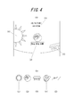
- FIG. 4A is a diagram illustrating an example in which a main screen when displaying information indicating a power control state by the energy management unit 20 is displayed on the display unit 12 of the display terminal 10. Further, as described above, in the following example, the input detection unit 14 that detects an input corresponding to the display on the display unit 12 is arranged on the front surface of the display unit 12, and a user's finger or the like is displayed on the display unit 12. It is possible to detect an input by a touch operation on the selected object.
- the display unit 12 of the display terminal 10 displays the icons associated with the items as the main screen. Display the object.
- an icon (1) representing the sun, an icon (2) representing a smart meter, and an icon (3) representing a house are displayed on the display unit 12.
- time and date (4) may be displayed as information useful for the user.
- FIG. 4A shows an example in which the above-described objects (1) to (3) are displayed as icon objects for detecting an operation by the user.
- the control unit 16 of the display terminal 10 performs control so that other icons follow and slide. That is, when the user detects an operation input for sliding the icon (2) representing the smart meter from right to left, for example, the control unit 16 follows the icons (1) and (3) and slides from right to left. Control to display. It is assumed that, for example, the icon (1) moves out of the display unit 12 and the icon (3) moves to the center of the display unit 12 as a result of such an operation. In this case, the control unit 16 controls the display unit 12 so that the next icon after the icon (3) appears at the right end of the display unit 12.
- the icons can be displayed one after another in a predetermined order based on detection of an operation input in which the user touches the icon and sweeps and slides.
- the icons displayed one after another in a predetermined order can be in the order shown in FIG. 4B, for example.
- the icon (4) shown in FIG. 4 (B) represents a magnetic tape reel on which data is recorded.
- the icon (5) shown in FIG. 4B represents a calendar.
- the control unit 16 may perform control so as to perform a display in which icons are looped as illustrated in FIG. For example, when icons as shown in FIG. 4B are displayed one after another on the display unit 12 as shown in FIG. 4A, for example, the icon (1) is next to the icon (5). Can be displayed. When the displayed icon is slid from the left to the right, the icon (5) can be displayed after the icon (1).
- a display that suggests what information is displayed based on an input to the icon may be performed. It can.
- a smart meter icon (2) is displayed at the center of the screen of the display unit 12, and information related to “power generation / storage / consumption” is selected at the bottom of the icon by selecting this icon.
- a display suggesting that it is displayed is performed.
- the control unit 16 acquires information about the smart meter from the energy management unit 20 and controls the display unit 12 to display the information. That is, for example, when the user touches the smart meter icon (2) shown in FIG. 4A with a finger or the like, as shown in FIG. 5, the display unit 12 displays “power generation” that is information associated with the smart meter. -Information related to “Storage / Consumption” is displayed. Further, for example, when the user touches the “power generation / storage / consumption” object shown in FIG. 4A with a finger or the like, the display as shown in FIG. 5 may be performed.
- FIG. 5 is a diagram illustrating a display of information related to “power generation / storage / consumption”, which is information associated with the smart meter, as an example of display on the display unit 12 of the display terminal 10.
- the display unit 12 includes a smart meter (connected device) icon (1), a power generation icon (2) by a solar panel, a charge / discharge icon (3) by a storage battery, and an electric appliance in the house.
- An icon (4) indicating the power consumption of the product and the state of the heat pump is displayed.
- the display unit 12 also displays an icon (5) for the accumulated power state, an icon (6) for the DR mode state, and an icon (7) indicating the power system.
- the display unit 12 also displays a button icon (8) for moving to the main screen and a back button icon (9).
- the icon of the part in which power is exchanged with the icons (1), (2), (3), and (4) shown in the center of FIG. 5 suggests the power conditioner 40.
- the smart meter icon (1) in FIG. 5 represents that 0.1 kW of power generated by the power control system (particularly the photovoltaic power generation system 50) is currently sold to a commercial power source. ing.
- the display of information related to “power generation / storage / consumption” shown in FIG. 5 it is preferable to represent the flow of power by moving an object such as an arrow, for example.
- an object such as an arrow
- the thick arrow is moved toward the smart meter icon (1), and the commercial power source is displayed from the smart meter icon (1).
- the user can easily grasp the state of power flow at a glance.
- the power control system is purchasing power from a commercial power source, it is preferable that the direction of the object indicated by the arrows and the direction of movement be reversed from those in the case of power sale.
- the control unit 16 acquires information through communication with the energy management unit 20, for example, smart as shown in FIG. Control is performed so that the detailed information associated with the meter is displayed on the display unit 12. That is, for example, when the user touches the smart meter icon (1) shown in FIG. 5 with a finger or the like, as shown in FIG. 6, the display unit 12 displays history information that is detailed information associated with the smart meter. Is done.
- FIG. 6 shows, as detailed information related to the smart meter, history information of power purchase from the commercial power supply and power sale to the commercial power supply, and consumption of the load devices 80-1 to 80-N connected to the power control system.
- An example in which power history information is displayed is shown.
- the graph displaying the history information shown in FIG. 6 is displayed by moving each axis of the graph by detecting an operation input of the user dragging the graph, for example, tracing back to the earlier history information. It is preferable to be able to do this. Further, in the graph displaying the history information shown in FIG.
- the user touches the graph with two fingers and then moves the touch position so that the distance between the two fingers is reduced or widened while keeping the touch (pinch-in / It is preferable that the scale of each axis can be changed by detecting an operation input to be pinched out.
- the scale of the time axis is, for example, one day (24 hours).
- the display can be in units of one month (for example, 30 days) or one year (12 months). For example, when the current day is March 12, transitions for one month from March 1 to March 31 including that day can be displayed in time series.
- the display follows the operation input of the sweep, It is preferable to be able to display the previous month or the next month.
- the one-month meter reading period for the electric power company to calculate the electricity bill may be assumed by the electric power company not necessarily from the first day of the month to the last day of the month. Therefore, when the transition of the power control state by the energy management unit 20 is displayed in time series, the transition of the control state of the power by the energy management unit in a predetermined period from a predetermined start point to a predetermined end point is used as a default display. Information can also be displayed. Such a predetermined period from the predetermined start point to the predetermined end point may be set in advance, or the user may be prompted to set when performing default display.
- control unit 16 transmits information on the transition of the power control state by the energy management unit 20 in a predetermined period from the set predetermined start point to the predetermined end point from the energy management unit 20. Control to get. In this way, the user can easily grasp the transition of the power control state by the energy management unit 20 on one screen for an arbitrary period such as a meter reading period for the electric power company to calculate the electricity bill, for example. Can do.
- the control unit 16 When the information on the transition of the power control state by the energy management unit 20 in a predetermined period is displayed, the control unit 16 defaults the predetermined period by detecting an input such as a double tap in the input detection unit 14, for example. You may control to memorize
- the control unit 16 receives the input from the input detection unit 14. Detectable.
- the control unit 16 calculates the distance by which such display is swept in the sweep direction. Change to the moved display. That is, when the transition of the control state of power by the energy management unit 20 is displayed in time series, when the input detection unit 14 detects an input moving in the time series direction corresponding to the time series display, the control unit 16 controls the display unit 12 to display the display following the movement of the input detected by the input detection unit 14.
- the control unit 16 manages the information on the transition of the power control state by the energy management unit 20 according to the time-series direction in which the input detected by the input detection unit 14 moves. Control is performed so as to obtain from the unit 20. For example, when the display of the transition of the control state of the power by the energy management unit 20 is moved by the input detected by the input detection unit 14 and a transition before the displayed time is displayed, before the time The information of the transition is acquired from the energy management unit 20. Similarly, for example, when the display of the transition of the control state of the power by the energy management unit 20 is moved by the input detected by the input detection unit 14 and a transition after the displayed time point is displayed, Information on transitions after that time is acquired from the energy management unit 20.
- the display by detecting an operation input or the like by which the user drags the display on the display unit 12, the display is moved in units of periods such as one month, or the period is further detailed. It can be moved.
- the display In order to distinguish between these two operations, for example, by detecting an input of an operation in which the user pays the display of the display unit 12, that is, an operation input to flick, the display is once performed in units of a predetermined period such as one month. Can be moved to.
- a breakdown of a predetermined period such as one month is made to follow the drag operation and gradually gradually. It can be made to move.
- the power generation icon (2) by the solar panel shown in FIG. 5 indicates that the power generated by the current solar power generation system 50 is 0.2 kW.
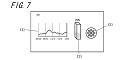
- the control unit 16 acquires information through communication with the energy management unit 20, and for example, a solar as shown in FIG. Control is performed so that detailed information associated with power generation by the panel is displayed on the display unit 12. That is, for example, when the user touches the icon (2) of the solar panel shown in FIG. 5 with a finger or the like, as shown in FIG. 7, the display unit 12 displays history information that is detailed information associated with power generation by the solar panel. Etc. are displayed.
- FIG. 7 shows history information (1) of power generation by the solar power generation system 50 and visual suggestions (2) and (3) of the current power generation status as detailed information associated with power generation by the solar panel. An example is shown. It is preferable that the graph displaying the power generation history information (1) by the solar power generation system 50 performs processing corresponding to each based on the same operation input as the graph described in FIG. .
- the object shown in (2) of FIG. 7 is a bar graph indicating what percentage of the maximum generated power (or rated output) the generated power of the current photovoltaic power generation system 50 is. For example, FIG. 7 shows that the generated power of the current solar power generation system 50 is 22% out of 100%.
- the object shown in (3) of FIG. 7 visually suggests the current power generation status of the solar power generation system 50.
- the speed at which the object such as the wheel shown in (3) of FIG. 7 rotates is changed according to the numerical value that is the basis of the object shown in (2) of FIG. 7 (for example, 22% in the example of FIG. 7).
- it can be displayed as a moving image. That is, if the generated power of the solar power generation system 50 increases, the speed of rotation of the object shown in (3) of FIG. 7 increases accordingly, and if the generated power of the solar power generation system 50 decreases, this increases. Accordingly, the rotation speed of the object shown in (3) of FIG. 7 is reduced, and the rotation of the object is stopped when power generation stops.
- the charging / discharging icon (3) by the storage battery shown in FIG. 5 indicates that the current power stored in the power storage unit 60 is 0.8 kW.
- the control unit 16 acquires information through communication with the energy management unit 20, for example, using a storage battery as illustrated in FIG. 8. Control is performed so that detailed information associated with charging / discharging is displayed on the display unit 12. That is, for example, when the user touches the storage battery icon (2) shown in FIG. 5 with a finger or the like, as shown in FIG. 8, the display unit 12 displays history information, which is detailed information associated with charging / discharging by the storage battery. Is displayed.
- FIG. 8 shows, as detailed information related to charging / discharging by the storage battery, charging / discharging history information (1) by the power storage unit 60 and visual suggestions (2) and (3) of the current charging / discharging status.
- An example is shown.
- the graph on which the power generation history information (1) by the power storage unit 60 is displayed is preferably subjected to processing corresponding to each based on the same operation input as the graph described in FIG.
- the object shown in (2) of FIG. 8 is a bar graph indicating what percentage of the maximum stored power the stored power in the current power storage unit 60 is.
- FIG. 7 shows that the current stored power (that is, remaining amount) of the power storage unit 60 is 7% out of 100%.
- the object shown in (3) of FIG. 8 visually suggests the current state of charge / discharge of the power storage unit 60.
- the direction and speed of rotation of an object such as a wheel shown in (3) of FIG. Can do. That is, the object rotates clockwise when the power storage unit 60 is charged, and rotates counterclockwise when discharged.
- the speed of rotation of the object shown in (3) of FIG. 8 increases accordingly, and if the power to charge or discharge the power storage unit 60 decreases, Accordingly, the rotation speed of the object shown in (3) of FIG. 8 is reduced, and the rotation stops when there is no charge or discharge.
- the object shown in (3) of FIG. 8 visually suggests whether the current power storage unit 60 is being charged or discharged at the outer periphery thereof. That is, a moving image in which a predetermined pattern (another object) expands or contracts is displayed on the outer peripheral portion of the rotating object shown in FIG. For example, a moving image that changes so that a predetermined pattern expands outward suggests a state in which the power storage unit 60 is discharged, and a moving image that changes so that the predetermined pattern contracts inward Is displayed to indicate the state of charging. In the example shown in (3) of FIG. 8, a state in which the power storage unit 60 is charged is suggested by displaying a pattern that changes so as to shrink inward on the outer peripheral portion of the rotating object. .
- the power consumption and heat pump status icon (4) shown in FIG. 5 indicates that the amount of hot water in the heat pump is 153 liters, and this amount corresponds to 51% of the hot water that can be accommodated in the entire heat pump. Represents. Further, this icon (4) represents that the power consumption of the load devices 80-1 to 80-N connected to the power control system is currently 0.2 kW.
- the control unit 16 acquires information through communication with the energy management unit 20 and consumes the electrical appliance as shown in FIG. Control to display detailed information associated with power and heat pump status. That is, for example, when the user touches the electrical appliance and heat pump icon (4) shown in FIG. 5 with a finger or the like, as shown in FIG. 9, the display unit 12 displays detailed information associated with the power consumption of the electrical appliance. Some history information is displayed.
- FIG. 9 shows an example in which history information of power consumption of the load devices 80-1 to 80-N and various information related to the power consumption are displayed as detailed information related to the power consumption of the electrical appliance. Yes.
- the graph displaying the power consumption history information and the like of the load devices 80-1 to 80-N is configured to perform processing corresponding to each based on the same operation input as the graph described in FIG. Is preferred.
- the transition of the electricity purchase price of the electricity to be purchased is displayed.
- the transition of the PV prediction for example, when prediction information related to photovoltaic power generation can be acquired from an external server such as the system EMS 200 shown in FIG. 1, the photovoltaic power generation system 50 can generate power based on this prediction information. It is preferable to display a prediction of power. Predictive information about solar power generation that can be obtained from such an external server can use information on services currently provided by specialized businesses.
- the transition of the PV prediction may be predicted by the energy management unit 20 based on the past transition (history) accumulated in the database 22. Furthermore, regarding the transition of the PV prediction, information based on the actual generated power by the photovoltaic power generation system 50 may be displayed for the past transition (history).
- the power purchase price of power purchased from a commercial power supply typically fluctuates in real time reflecting the hourly change in the wholesale power market price, such as real-time pricing (RTP). It can also be an electricity bill.
- RTP real-time pricing
- the information up to the current time point is stored in the past history of the time change of the power control state by the energy management unit 20.
- the display can be performed based on this.
- the information from the current time point is the time based on the prediction based on the past history of the time change of the power control state by the energy management unit 20, or the time of the power control state by the energy management unit 20 based on the information acquired from the external server.
- a change prediction can be displayed.
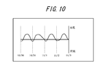
- the icon (5) of the accumulated power state shown in FIG. 5 represents that the accumulated power sold up to now is 99 kWh and the accumulated power purchased up to now is 99 kWh.
- An arbitrary predetermined time point such as the beginning of the month can be set as the time point as the starting point for accumulating such accumulated values.
- the control unit 16 acquires information through communication with the energy management unit 20 and, for example, a state of accumulated power as illustrated in FIG. Controls to display detailed information associated with. That is, for example, when the user touches the accumulated power icon (5) shown in FIG. 5 with a finger or the like, as shown in FIG. 10, the display unit 12 displays history information that is detailed information associated with the accumulated power state. Is displayed.
- FIG. 10 shows an example in which history information of power sold and purchased by the power control system according to the present embodiment is displayed as detailed information associated with the state of accumulated power. It is preferable to perform processing corresponding to each of the graphs on which the power sale and power purchase history information is displayed based on the same operation input as the graph described in FIG.
- the DR mode state icon (6) shown in FIG. 5 represents demand response information (DR information: demand response information) from an electric power company or the like, and “Normal” shown in FIG. This means that there is no request for households to reduce power consumption.
- DR 20% means that the power system is requested to reduce the power consumption of each household by 20%.
- DR 50% means that the power system requests that the power consumption of each household be reduced by 50%.
- “Emergency” means that the power supply of the power system is in an emergency, and that each household is required to operate independently if it can operate independently and sell if there is power available. Means.
- “Isolated” means that each household is required to operate independently. In the example illustrated in FIG. 5, it is indicated that the DR mode is “Normal”, and thus the user can grasp at a glance that there is no abnormality in the supply state of power from the power system.
- the energy management unit 20 when the DR mode is not “Normal” as described above and the request for reducing the power consumption of each home is received, the energy management unit 20 responds to the request with the load devices 80-1 ⁇ 80. Various controls such as reducing the power consumption of 80-N can also be performed. That is, when the DR mode is “Emergency” and there is a request to sell if there is power that can be sold, the energy management unit 20 responds to the request by, for example, the power generated by the photovoltaic power generation system 50. Control is performed so that at least a part of the power is sold to the power system.
- the energy management unit 20 discharges the power generated by the photovoltaic power generation system 50 and the power storage unit 60 in response to the request. Control is performed so that the self-sustained operation is performed by at least one of the electric powers. Even when the control state of power by the energy management unit 20 is changed in this way, the control unit 16 acquires the information after the change from the energy management unit 20 and obtains the information based on a predetermined value based on the application software.
- the display unit 12 is controlled to display in the display mode.
- the control unit 16 displays information such as information from the power system and the power such as the electricity charge for the most recent months. It can be controlled to display information related to the system.
- control unit 16 displays the main screen as shown in FIG. 4A, for example. To control.
- control unit 16 When an operation input for selecting the icon (9) of the back button shown in FIG. 5 by the user is detected, the control unit 16 displays the screen that was displayed immediately before the screen that is currently displayed on the display unit 12. To control. It is preferable to return to the display of the previous screen at any time on each display screen by displaying the back button icon (9) shown in FIG. 5 also on each screen after FIG. It is.
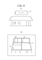
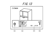
- a display suggesting what information is displayed in the vicinity of the icon displayed in the center of the screen of the display unit 12 based on an input to the icon. Can be done. Therefore, for example, in FIG. 4A, when an operation input in which the user slides the icon (3) representing the house to the center of the screen is detected, the control unit 16 performs the operation as shown in FIG. Control is performed so as to indicate that information related to “status” is displayed by selecting an icon.
- “status” means the state of each of the load devices 80-1 to 80-N installed inside and outside the house that employs the power control system according to the present embodiment.
- the control unit 16 When the display as shown in FIG. 11A is performed, for example, when the input detection unit 14 detects an operation input corresponding to the display of the house icon, the control unit 16 relates to the status of any load device. Control to display information to display or to let the user select information. That is, for example, when the user touches the house icon shown in FIG. 11A with a finger or the like, the display unit 12 adopts the power control system according to the present embodiment as shown in FIG. The floor plan of the house is schematically displayed. For example, when the user touches the “status” object shown in FIG. 11A with a finger or the like, the display shown in FIG. 11B may be performed.
- the floor plan display of the house that employs the power control system according to the present embodiment indicates the location where the load devices 80-1 to 80-N are installed inside and outside the house. Used to show. That is, in the floor plan display shown in FIG. 11B, the locations (1), (2), (3), and (4) to which the respective numbers are attached are located at the load devices 80-1 to 80-N. Indicates that one of these is installed. In FIG. 11B, for simplification of the figure, only the numbers of the places where the load devices 80-1 to 80-N are installed are shown. However, the load devices actually installed at each location are shown. An icon based on the type may be displayed. For example, in FIG. 11B, an icon representing a television may be displayed at a place where the television is installed.
- FIG. 11B information indicating the power control state by the energy management unit 20 associated with the display of the number assigned to each place where the load device is installed will be described.
- the control unit 16 Control is performed so that information indicating the state is acquired from the energy management unit 20 and displayed. That is, when an operation input for selecting the position (1) shown in FIG. 11B by the user is detected, the control unit 16 acquires information through communication with the energy management unit 20, for example, in FIG. As shown, detailed information associated with the air conditioner 1 is controlled to be displayed on the display unit 12. For example, when the user touches the position (1) shown in FIG. 11B with a finger or the like, various kinds of detailed information associated with the air conditioner 1 are displayed on the display unit 12 as shown in FIG. .
- the detailed information associated with the air conditioner 1 shown in FIG. 12 indicates each status of the air conditioner 1 as described below.
- the power on display (1) indicates that the power of the air conditioner 1 is on.
- the display (2) of the set temperature and set humidity indicates that the temperature set in the air conditioner 1 is 20 degrees and the humidity set in the air conditioner 1 is 34%.
- the actual temperature measured in the air conditioner 1 is 24 degrees, the actual humidity is 51%, and the current power consumption in the air conditioner 1 is 61393W. Represents.
- the history icon display (4) when the input detection unit 14 detects an operation input corresponding to the icon, the control unit 16 acquires history information indicating a transition of power consumption of the air conditioner 1 from the energy management unit 20. And control to display.
- the control unit 16 changes the state of the refrigerator-freezer. Control is performed so that the information to be displayed is acquired from the energy management unit 20 and displayed. That is, when an operation input for selecting the position (2) shown in FIG. 11B by the user is detected, the control unit 16 acquires information through communication with the energy management unit 20, for example, in FIG. 13. As shown, detailed information associated with the refrigerator-freezer is controlled to be displayed on the display unit 12. For example, when the user touches the position (2) shown in FIG. 11B with a finger or the like, as shown in FIG. 13, various kinds of detailed information associated with the refrigerator-freezer are displayed. .
- the detailed information associated with the refrigerator-freezer shown in FIG. 13 indicates each status of the refrigerator-freezer as described below.
- the power-on display (1) indicates that the power supply of the refrigerator-freezer is turned on.
- the display (2) of the refrigerator compartment temperature and the freezer compartment temperature indicates that the temperature measured in the refrigerator compartment is 7 degrees and the temperature measured in the freezer compartment is 1 degree.
- the power display (3) indicates that the current power consumption in the refrigerator-freezer is 22852W.
- the control unit 16 acquires history information representing a transition of power consumption of the refrigerator-freezer from the energy management unit 20. And control to display.
- the control unit 16 Control is performed so that information indicating the state is acquired from the energy management unit 20 and displayed. That is, when an operation input for selecting a position (3) shown in FIG. 11B by the user is detected, the control unit 16 acquires information through communication with the energy management unit 20, for example, in FIG. As shown, detailed information associated with the television 1 is controlled to be displayed on the display unit 12. For example, when the user touches the position (3) shown in FIG. 11B with a finger or the like, various detailed information associated with the television 1 is displayed on the display unit 12 as shown in FIG. .
- the detailed information associated with the television 1 shown in FIG. 14 indicates each status of the television 1 as described below.
- the power off display (1) indicates that the power of the television 1 is off.
- the screen brightness (brightness) display (2) of the television 1 indicates that the screen brightness setting by the backlight of the television 1 is -15, for example.
- the power display (3) indicates that the current power consumption of the television 1 is 0 W.
- the control unit 16 acquires from the energy management unit 20 history information representing a transition of power consumption of the television 1 and the like. And control to display.
- the control unit 16 when a heat pump is installed at the position (4) shown in FIG. 11B, when the input detection unit 14 detects an operation input corresponding to the position, the control unit 16 indicates information indicating the state of the heat pump. Is acquired from the energy management unit 20 and displayed. That is, when the operation input for selecting the position (4) shown in FIG. 11B by the user is detected, the control unit 16 acquires information through communication with the energy management unit 20, for example, in FIG. As shown, detailed information associated with the heat pump is controlled to be displayed on the display unit 12. For example, when the user touches the position (4) shown in FIG. 11B with a finger or the like, various detailed information associated with the heat pump is displayed on the display unit 12 as shown in FIG.
- the detailed information associated with the heat pump shown in FIG. 15 indicates each status of the heat pump as described below.
- the power-on display (1) indicates that the heat pump is turned on.
- the boiler mode and set temperature display (2) indicate that the operation mode set for the boiler is the normal mode and the temperature set for the boiler is 16 degrees.
- the hot water display (3) can indicate the amount of hot water in the boiler in, for example, five levels.
- Boiler temperature, ambient temperature, and power display (4) shows that the actual temperature measured at the boiler is 4 degrees, the temperature measured around the boiler is 3 degrees, and the power consumption in the current heat pump Is 53580W.
- the control unit 16 acquires history information indicating a transition of the power consumption of the heat pump from the energy management unit 20. Control to display.
- a display suggesting what information is displayed in the vicinity of the icon displayed in the center of the screen of the display unit 12 based on an input to the icon. Can be done. For example, on the screen as shown in FIG. 4A, when an operation input is detected in which the user slides the icon (5) shown in FIG. As shown in the figure, control is performed so that the “comparison” object (1) and the “plan” object (2) are displayed in the vicinity of this icon. In this way, it is possible to suggest that information indicating the control state of two or more different powers by the energy management unit 20 is displayed for one icon.
- FIG. 16B shows a state in which the status of the power sale and power purchase in the house described in this example is compared with the status of the power sale and power purchase in other homes.
- the graph of “A house” represents the situation of the power sale and power purchase of the house described in this example
- the graphs of “B house” and “C house” represent the power sale and power purchase in other households. It can represent the situation.
- selecting other households to be compared for example, in consideration of privacy issues, the load equipment installation status or power consumption similar to the house described in this example It is preferable that other households having a situation or the like are selected anonymously.
- the energy management unit 20 is connected to the network 300. Therefore, for example, the system EMS 200 installed in an electric power company or the like can collect various types of information stored in the database 22 of the energy management unit 20 of each home. For this reason, in this embodiment, system EMS200 can select the information of each household suitably, and can provide the other households anonymously, and can compare the situation of the above-mentioned power sale and power purchase. it can.
- a submenu related to “plan” can be displayed.
- the “submenu” can be displayed including, for example, “operation plan display”, “load pattern”, “electricity charge signal”, and the like.
- the “operation plan display” indicates, for example, an operation plan of the photovoltaic power generation system 50, the power storage unit 60, and the like, and by proceeding to the display screen, for example, a future operation based on the past operation history.
- An operation plan prediction or a preset future operation plan can be displayed.
- the “load pattern” indicates, for example, the load pattern of the load devices 80-1 to 80-N, and by proceeding to the display screen, for example, the future load based on the past load pattern Pattern predictions can be displayed.
- the “electricity charge” means, for example, information based on a charge signal of the electricity charge, and by proceeding to the display screen, for example, the future electricity charge based on the transition of the charge signal of the past electricity charge. It is possible to display a prediction of the charge signal.
- the energy management unit 20 may acquire information such as prediction of electricity charges provided by a specialized business operator from an external server, and display such information.
- weather indicates, for example, weather forecast information
- information such as weather, temperature, and humidity is appropriately displayed using graphics.
- the energy management unit 20 can acquire and display the weather forecast information provided by a specialized business operator via a network at a predetermined timing.
- weather-related power can display, for example, the amount of solar radiation and the outside temperature together with information related to power.
- information such as the current degree of solar radiation and temperature is displayed using graphics as appropriate together with the power generation status of the solar power generation system 50 and the power storage status of the power storage unit 60.
- information related to the weather can also be acquired and displayed by the energy management unit 20 at a predetermined timing through information provided by a specialized business operator via a network.
- the “history” of each piece of information stored in the energy management unit 20 is displayed. It can be displayed.
- the user touches the reel icon (4) of the magnetic tape shown in FIG. 4B with a finger or the like it is possible to proceed to the floor plan display as shown in FIG. 11B.
- the floor plan display described with reference to FIG. 11B indicates the place where the load devices 80-1 to 80-N are installed. Therefore, for example, when the reel icon (4) of the magnetic tape shown in FIG. 4B is selected and the display shifts to the display of FIG. 11B, an input corresponding to the position of each load device 80 is detected.
- Such power consumption history of the load device 80 can be accumulated in the database 22 of the energy management unit 20. It is preferable that the history of the power consumption of the load device 80 displayed here can be easily grasped by the user at a glance, for example, displayed as a graph.
- the reel icon (4) of the magnetic tape shown in FIG. 4B is selected, a predetermined icon or object is displayed, and an input corresponding to the icon or object is detected. It is possible to display a history of items related to the display in which is detected.
- the display terminal 10 As described above, according to the display terminal 10 according to the present embodiment, even a general user who is not a power control expert can easily grasp the power control state in the power control system at a glance.
- the input detection unit 14 is mainly a touch panel
- the input detection unit that detects the input corresponding to the display on the display unit is not limited to the touch panel, and may be configured by, for example, up, down, left, and right direction keys.
- the touch panel for detecting the operation input such as sweep or drag, or the operation input in the up / down / left / right directions is detected as in the above-described embodiment. It is possible to employ various types of input detection units such as direction keys.
- the display on the display unit 12 described in the above-described embodiment is an example, and other than the above-described example, a general user can easily grasp the power control state in the power control system at a glance.
- Various displays can be assumed.
- Various types of application software can be assumed for displaying the information indicating the control state of power as described above in a display mode that can be easily understood by a general user at a glance. .
Abstract
Description
発電システムおよび蓄電システムの少なくとも一方に接続されたパワーコンディショナ、前記パワーコンディショナおよび商用電源に接続された接続機器、ならびに前記パワーコンディショナを介して電力を供給される負荷機器、と通信可能なエネルギー管理部における電力の制御状態を示す情報を表示する表示端末であって、
表示部と、
前記表示部における表示に対応する入力を検出する入力検出部と、
前記入力検出部が前記表示部における表示に対応する入力を検出すると、当該表示に関連付けられた前記エネルギー管理部による電力の制御状態を示す情報を前記エネルギー管理部から取得して、当該電力の制御状態を示す情報を所定の表示態様で表示するように前記表示部を制御する制御部と、
を備えることを特徴とするものである。
前記制御部は、当該接続機器を示唆する画像に関連付けられた前記エネルギー管理部による電力の制御状態を示す情報として、前記商用電源からの買電および該商用電源への売電に関する情報ならびに電気料金に関する情報のうち少なくとも1つを前記エネルギー管理部から取得して、当該情報を前記所定の表示態様で表示するように前記表示部を制御するのが好ましい。
前記制御部は、前記入力検出部が検出した入力が示唆する移動方向に応じて、前記エネルギー管理部による電力の制御状態の遷移の情報を前記エネルギー管理部から取得して、当該情報を、前記入力検出部が検出した入力の移動に追従させて、前記所定の表示態様で表示するように前記表示部を制御するのが好ましい。
前記制御部は、当該負荷機器を示唆する画像に関連付けられた前記エネルギー管理部による電力の制御状態を示す情報を前記エネルギー管理部から取得して、当該電力の制御状態を示す情報を前記所定の表示態様で表示するように前記表示部を制御するのが好ましい。
前記制御部は、前記エネルギー管理部による電力の制御状態が変更された後の状態を示す情報を前記エネルギー管理部から取得して、当該状態を示す情報を前記所定の表示態様で表示するように前記表示部を制御するのが好ましい。
前記制御部は、前記エネルギー管理部による電力の制御状態が変更された後の状態を示す情報を前記エネルギー管理部から取得して、当該状態を示す情報を前記所定の表示態様で表示するように前記表示部を制御するのが好ましい。
前記制御部は、前記エネルギー管理部による電力の制御状態が変更された後の状態を示す情報を前記エネルギー管理部から取得して、当該状態を示す情報を前記所定の表示態様で表示するように前記表示部を制御するのが好ましい。
発電システムおよび蓄電システムの少なくとも一方に接続されるとともに負荷機器にも接続されたパワーコンディショナ、前記パワーコンディショナおよび商用電源に接続された接続機器、前記パワーコンディショナおよび前記接続機器および前記負荷機器と通信可能なエネルギー管理部、ならびに前記エネルギー管理部と通信する表示端末、を含む電力制御システムであって、
前記表示端末は、
前記エネルギー管理部による電力の制御状態を示す情報を表示する表示部と、
前記表示部における表示に対応する入力を検出する入力検出部と、
前記入力検出部が前記表示部における表示に対応する入力を検出すると、当該表示に関連付けられた前記エネルギー管理部による電力の制御状態を示す情報を前記エネルギー管理部から取得して、当該電力の制御状態を示す情報を所定の表示態様で表示するように前記表示部を制御する制御部と、
を備えることを特徴とするものである。
発電システムおよび蓄電システムの少なくとも一方に接続されたパワーコンディショナ、前記パワーコンディショナおよび商用電源に接続された接続機器、ならびに前記パワーコンディショナを介して電力を供給される負荷機器、と通信可能なエネルギー管理部と通信する、表示部を備えた表示端末の表示方法であって、
前記エネルギー管理部による電力の制御状態を示す情報を前記表示部に表示する表示ステップと、
前記表示部における表示に対応する入力を検出する入力検出ステップと、
前記入力検出ステップにて前記表示部における表示に対応する入力を検出すると、当該表示に関連付けられた前記エネルギー管理部による電力の制御状態を示す情報を前記エネルギー管理部から取得して、当該電力の制御状態を示す情報を所定の表示態様で表示するように前記表示部を制御する制御ステップと、
を備えることを特徴とするものである。
12 表示部
14 入力検出部
16 制御部
18 インタフェース
20 エネルギー管理部
22 データベース
30 スマートメータ
40 パワーコンディショナ
50 太陽光発電システム
60 蓄電部
70 分電盤
80 負荷機器
100 商用電源
200 系統EMS
210 データベース
300 ネットワーク
Claims (14)
- 発電システムおよび蓄電システムの少なくとも一方に接続されたパワーコンディショナ、前記パワーコンディショナおよび商用電源に接続された接続機器、ならびに前記パワーコンディショナを介して電力を供給される負荷機器、と通信可能なエネルギー管理部における電力の制御状態を示す情報を表示する表示端末であって、
表示部と、
前記表示部における表示に対応する入力を検出する入力検出部と、
前記入力検出部が前記表示部における表示に対応する入力を検出すると、当該表示に関連付けられた前記エネルギー管理部による電力の制御状態を示す情報を前記エネルギー管理部から取得して、当該電力の制御状態を示す情報を所定の表示態様で表示するように前記表示部を制御する制御部と、
を備えることを特徴とする表示端末。 - 前記表示部に前記接続機器を示唆する画像が表示されている際に、前記接続機器を示唆する当該画像の表示に対応する入力を前記入力検出部が検出すると、
前記制御部は、当該接続機器を示唆する画像に関連付けられた前記エネルギー管理部による電力の制御状態を示す情報として、前記商用電源からの買電および該商用電源への売電に関する情報ならびに電気料金に関する情報のうち少なくとも1つを前記エネルギー管理部から取得して、当該情報を前記所定の表示態様で表示するように前記表示部を制御する、請求項1に記載の表示端末。 - 前記制御部は、前記エネルギー管理部による電力の制御状態の遷移を時系列で表示する際、現在時点までの情報は、前記電力の制御状態の遷移の過去の履歴に基づいて表示を行うとともに、現在時点から先の情報は、前記エネルギー管理部による前記過去の履歴に基づく予測または外部サーバから取得する前記電力の制御状態の遷移の予測に基づいて表示を行うように前記表示部を制御する、請求項1または2に記載の表示端末。
- 前記制御部は、前記エネルギー管理部による電力の制御状態の遷移を時系列で表示する際、所定の期間における前記エネルギー管理部による電力の制御状態の遷移の情報を前記エネルギー管理部から取得して、当該情報を前記所定の表示態様で表示するように前記表示部を制御する、請求項1から3のいずれか一項に記載の表示端末。
- 前記エネルギー管理部による電力の制御状態の遷移が前記表示部に時系列で表示されている際に、前記入力検出部が前記時系列の表示に対応する当該時系列方向への移動を示唆する入力を検出すると、
前記制御部は、前記入力検出部が検出した入力が示唆する移動方向に応じて、前記エネルギー管理部による電力の制御状態の遷移の情報を前記エネルギー管理部から取得して、当該情報を、前記入力検出部が検出した入力の移動に追従させて、前記所定の表示態様で表示するように前記表示部を制御する、請求項1から4のいずれか一項に記載の表示端末。 - 前記制御部は、前記エネルギー管理部による電力の制御状態を示す情報として前記発電システムの発電に関する情報を表示する際、当該発電している電力の大きさを所定のオブジェクトの回転速度あるいは回転方向により示唆する表示を行うように前記表示部を制御する、請求項1から5のいずれか一項に記載の表示端末。
- 前記制御部は、前記エネルギー管理部による電力の制御状態を示す情報として前記蓄電システムの充電または放電に関する情報を表示する際、所定のオブジェクトが外向きに膨張するように変化する動画により前記放電している状態を示唆し、当該所定のオブジェクトが内向きに収縮するように変化する動画により前記充電している状態示唆する表示を行うように前記表示部を制御する、請求項1から6のいずれか一項に記載の表示端末。
- 前記表示部に前記負荷機器を示唆する画像が表示されている際に、前記入力検出部が前記負荷機器を示唆する画像の表示に対応する入力を検出すると、
前記制御部は、当該負荷機器を示唆する画像に関連付けられた前記エネルギー管理部による電力の制御状態を示す情報を前記エネルギー管理部から取得して、当該電力の制御状態を示す情報を前記所定の表示態様で表示するように前記表示部を制御する、請求項1から7のいずれか一項に記載の表示端末。 - 前記制御部は、前記エネルギー管理部による電力の制御状態を示す情報として、前記商用電源から供給される電力について需要応答に関する情報または当該電力の買電価格に関する情報を前記エネルギー管理部から取得して、当該電力の制御状態を示す情報を前記所定の表示態様で表示するように前記表示部を制御する、請求項1から8のいずれか一項に記載の表示端末。
- 前記商用電源から供給される電力について需要応答に関する情報に基づいて前記エネルギー管理部による電力の制御状態が変更された場合、
前記制御部は、前記エネルギー管理部による電力の制御状態が変更された後の状態を示す情報を前記エネルギー管理部から取得して、当該状態を示す情報を前記所定の表示態様で表示するように前記表示部を制御する、請求項1から9のいずれか一項に記載の表示端末。 - 前記需要応答に関する情報として前記商用電源からの電力供給が非常事態である旨の情報に基づいて、前記エネルギー管理部による電力の制御状態が、前記発電システムにより発電される電力を前記商用電源に売電している状態に変更された場合、
前記制御部は、前記エネルギー管理部による電力の制御状態が変更された後の状態を示す情報を前記エネルギー管理部から取得して、当該状態を示す情報を前記所定の表示態様で表示するように前記表示部を制御する、請求項10に記載の表示端末。 - 前記需要応答に関する情報として前記発電システムおよび前記蓄電システムの少なくとも一方の電力により自立運転を指示する旨の情報に基づいて、前記エネルギー管理部による電力の制御状態が、前記発電システムおよび前記蓄電システムの少なくとも一方の電力により自立運転している状態に変更された場合、
前記制御部は、前記エネルギー管理部による電力の制御状態が変更された後の状態を示す情報を前記エネルギー管理部から取得して、当該状態を示す情報を前記所定の表示態様で表示するように前記表示部を制御する、請求項10または11に記載の表示端末。 - 発電システムおよび蓄電システムの少なくとも一方に接続されるとともに負荷機器にも接続されたパワーコンディショナ、前記パワーコンディショナおよび商用電源に接続された接続機器、前記パワーコンディショナおよび前記接続機器および前記負荷機器と通信可能なエネルギー管理部、ならびに前記エネルギー管理部と通信する表示端末、を含む電力制御システムであって、
前記表示端末は、
前記エネルギー管理部による電力の制御状態を示す情報を表示する表示部と、
前記表示部における表示に対応する入力を検出する入力検出部と、
前記入力検出部が前記表示部における表示に対応する入力を検出すると、当該表示に関連付けられた前記エネルギー管理部による電力の制御状態を示す情報を前記エネルギー管理部から取得して、当該電力の制御状態を示す情報を所定の表示態様で表示するように前記表示部を制御する制御部と、
を備えることを特徴とする、電力制御システム。 - 発電システムおよび蓄電システムの少なくとも一方に接続されたパワーコンディショナ、前記パワーコンディショナおよび商用電源に接続された接続機器、ならびに前記パワーコンディショナを介して電力を供給される負荷機器、と通信可能なエネルギー管理部と通信する、表示部を備えた表示端末の表示方法であって、
前記エネルギー管理部による電力の制御状態を示す情報を前記表示部に表示する表示ステップと、
前記表示部における表示に対応する入力を検出する入力検出ステップと、
前記入力検出ステップにて前記表示部における表示に対応する入力を検出すると、当該表示に関連付けられた前記エネルギー管理部による電力の制御状態を示す情報を前記エネルギー管理部から取得して、当該電力の制御状態を示す情報を所定の表示態様で表示するように前記表示部を制御する制御ステップと、
を備えることを特徴とする表示端末の表示方法。
Priority Applications (2)
| Application Number | Priority Date | Filing Date | Title |
|---|---|---|---|
| US14/365,159 US20140336837A1 (en) | 2011-12-14 | 2012-01-13 | Display terminal, power control system, and display method |
| EP12857188.2A EP2793344A4 (en) | 2011-12-14 | 2012-01-13 | DISPLAY TERMINAL, POWER CONTROL SYSTEM, AND DISPLAY METHOD |
Applications Claiming Priority (2)
| Application Number | Priority Date | Filing Date | Title |
|---|---|---|---|
| JP2011-273865 | 2011-12-14 | ||
| JP2011273865 | 2011-12-14 |
Publications (1)
| Publication Number | Publication Date |
|---|---|
| WO2013088584A1 true WO2013088584A1 (ja) | 2013-06-20 |
Family
ID=48612068
Family Applications (1)
| Application Number | Title | Priority Date | Filing Date |
|---|---|---|---|
| PCT/JP2012/000192 WO2013088584A1 (ja) | 2011-12-14 | 2012-01-13 | 表示端末、電力制御システム、および表示方法 |
Country Status (4)
| Country | Link |
|---|---|
| US (1) | US20140336837A1 (ja) |
| EP (1) | EP2793344A4 (ja) |
| JP (2) | JPWO2013088584A1 (ja) |
| WO (1) | WO2013088584A1 (ja) |
Cited By (14)
| Publication number | Priority date | Publication date | Assignee | Title |
|---|---|---|---|---|
| WO2015016288A1 (ja) * | 2013-07-30 | 2015-02-05 | 三菱電機株式会社 | エネルギー管理システム、表示装置、表示方法及びプログラム |
| JP2015042927A (ja) * | 2013-08-26 | 2015-03-05 | 株式会社東芝 | 消費電力出力装置 |
| JP2015070680A (ja) * | 2013-09-27 | 2015-04-13 | パナソニック株式会社 | エネルギー管理装置及び方法、並びにエネルギー管理システム |
| JP2015226451A (ja) * | 2014-05-30 | 2015-12-14 | 三菱電機株式会社 | コントローラ及び表示コントローラ |
| CN105431997A (zh) * | 2014-01-08 | 2016-03-23 | 因福美地股份有限公司 | 信号处理系统、信号处理方法以及信号处理程序 |
| JP2016127734A (ja) * | 2015-01-06 | 2016-07-11 | 住友電気工業株式会社 | 充電制御装置、電力システム、端末装置、充電制御方法および充電制御プログラム |
| KR20160089231A (ko) * | 2015-01-19 | 2016-07-27 | 엘에스산전 주식회사 | 태양광발전 장치의 데이터 수집 장치 |
| JP2017093290A (ja) * | 2015-06-08 | 2017-05-25 | 京セラ株式会社 | 電力変換装置、電力管理装置及び電力管理方法 |
| JP2017107531A (ja) * | 2015-12-08 | 2017-06-15 | 旭化成ホームズ株式会社 | 住宅 |
| JPWO2017022077A1 (ja) * | 2015-08-04 | 2018-05-24 | 三菱電機株式会社 | 電力制御装置、コスト表示方法、及び、プログラム |
| JP2018108022A (ja) * | 2014-07-11 | 2018-07-05 | 東芝ライテック株式会社 | 表示装置、表示方法及び表示プログラム |
| JP2020510945A (ja) * | 2017-02-13 | 2020-04-09 | グリディ ホールディングス エルエルシーGriddy Holdings Llc | 公益事業関する市場向けプラットフォームの自動化方法及びシステム |
| JP2020078242A (ja) * | 2013-07-26 | 2020-05-21 | 京セラ株式会社 | 電力管理装置、および電力管理方法 |
| JP2020188679A (ja) * | 2017-10-16 | 2020-11-19 | 住友電気工業株式会社 | 表示プログラム、端末装置、および電力管理システム |
Families Citing this family (28)
| Publication number | Priority date | Publication date | Assignee | Title |
|---|---|---|---|---|
| JP5891931B2 (ja) * | 2012-04-27 | 2016-03-23 | ソニー株式会社 | 表示制御装置、表示制御方法、表示制御プログラムおよび携帯端末 |
| KR101354895B1 (ko) * | 2012-06-01 | 2014-01-23 | 엘에스산전 주식회사 | 전력 감시 시스템 및 전력 시스템 정보 디스플레이 방법 |
| JP6122654B2 (ja) * | 2013-02-20 | 2017-04-26 | 大和ハウス工業株式会社 | エネルギー使用状況表示システム及びエネルギー使用状況表示方法 |
| CN105408898B (zh) | 2013-03-15 | 2019-05-28 | 弗兰克公司 | 测量数据的自动记录和图形生成 |
| US10453154B2 (en) * | 2013-08-09 | 2019-10-22 | Panasonic Intellectual Property Management Co., Ltd. | Power adjustment system, power adjustment method, and computer program |
| JP6160957B2 (ja) * | 2013-09-30 | 2017-07-12 | パナソニックIpマネジメント株式会社 | 電力管理装置、電力管理方法、プログラム |
| US10998754B2 (en) * | 2015-01-30 | 2021-05-04 | Sony Corporation | Device and method for controlling transfer of DC power between nodes |
| WO2016199816A1 (ja) * | 2015-06-08 | 2016-12-15 | 京セラ株式会社 | 電力変換装置、電力管理装置及び電力管理方法 |
| US9960637B2 (en) * | 2015-07-04 | 2018-05-01 | Sunverge Energy, Inc. | Renewable energy integrated storage and generation systems, apparatus, and methods with cloud distributed energy management services |
| US10147984B2 (en) | 2015-07-31 | 2018-12-04 | SynCells, Inc. | Portable and modular energy storage for multiple applications |
| WO2017169585A1 (ja) * | 2016-03-29 | 2017-10-05 | 京セラ株式会社 | 管理システム、管理方法、電力変換装置及び管理装置 |
| JP6736957B2 (ja) * | 2016-04-25 | 2020-08-05 | 住友電気工業株式会社 | 表示プログラム、端末装置、および電力管理システム |
| US11036192B2 (en) * | 2016-06-08 | 2021-06-15 | SaLisa Berrien | COI optimizer |
| JP6868795B2 (ja) * | 2017-04-28 | 2021-05-12 | パナソニックIpマネジメント株式会社 | 情報表示方法、情報表示システム、および情報表示プログラム |
| US11394573B2 (en) | 2017-06-13 | 2022-07-19 | SynCells, Inc. | Energy virtualization layer with a universal smart gateway |
| US11125461B2 (en) | 2017-06-13 | 2021-09-21 | Gerard O'Hora | Smart vent system with local and central control |
| US10203738B2 (en) * | 2017-06-13 | 2019-02-12 | SynCells, Inc. | Energy virtualization layer for commercial and residential installations |
| WO2018231932A1 (en) * | 2017-06-13 | 2018-12-20 | SynCells, Inc. | Energy virtualization layer with a universal smart gateway and modular energy storage |
| US11271766B2 (en) * | 2017-06-13 | 2022-03-08 | SynCells, Inc. | Energy virtualization layer with a universal smart gateway |
| EP3700772A4 (en) | 2017-10-20 | 2021-07-21 | SynCells, Inc. | ROBOTICS FOR ROTATING ENERGY CELLS IN VEHICLES |
| AU2018398489B2 (en) * | 2017-12-25 | 2023-06-15 | Gs Yuasa International Ltd. | Information processing device, information processing system, information processing method, and computer program |
| JP7063669B2 (ja) * | 2018-03-23 | 2022-05-09 | シャープ株式会社 | 電力情報作成装置および電力情報表示システム |
| US20220229115A1 (en) * | 2019-04-26 | 2022-07-21 | Gs Yuasa International Ltd. | Information processing device, information processing system, information processing method, and computer program |
| JPWO2021005707A1 (ja) * | 2019-07-09 | 2021-01-14 | ||
| CN114616736A (zh) * | 2019-09-11 | 2022-06-10 | 萨万特系统公司 | 能量管理系统和方法 |
| JP2022080767A (ja) * | 2020-11-18 | 2022-05-30 | トヨタ自動車株式会社 | 制御装置、プログラム及び制御方法 |
| EP4047773A1 (en) * | 2021-02-18 | 2022-08-24 | Stefan Grosjean | Energy management system |
| EP4177817A1 (en) * | 2021-11-09 | 2023-05-10 | Yanmar Holdings Co., Ltd. | Display unit |
Citations (5)
| Publication number | Priority date | Publication date | Assignee | Title |
|---|---|---|---|---|
| JP2002296307A (ja) * | 2001-03-29 | 2002-10-09 | Sekisui Chem Co Ltd | 電力モニタ装置 |
| JP2002297229A (ja) * | 2001-03-30 | 2002-10-11 | Sekisui Chem Co Ltd | 生活情報表示装置および生活情報表示用プログラムおよび生活情報表示用プログラムを記録した記録媒体 |
| JP2003309928A (ja) | 2002-04-16 | 2003-10-31 | Nippon Futo Soko Kk | 電力管理システム |
| JP2008161037A (ja) * | 2006-11-30 | 2008-07-10 | Matsushita Electric Works Ltd | エネルギー機器稼動状況表示モニター |
| JP2011003449A (ja) | 2009-06-19 | 2011-01-06 | Tokai Koshi:Kk | 発電システム |
Family Cites Families (40)
| Publication number | Priority date | Publication date | Assignee | Title |
|---|---|---|---|---|
| JP3406760B2 (ja) * | 1996-01-26 | 2003-05-12 | 株式会社東芝 | 監視制御装置 |
| JPH1141816A (ja) * | 1997-07-17 | 1999-02-12 | Nissin Electric Co Ltd | 太陽光発電装置 |
| US6795798B2 (en) * | 2001-03-01 | 2004-09-21 | Fisher-Rosemount Systems, Inc. | Remote analysis of process control plant data |
| JP3540760B2 (ja) * | 2001-03-27 | 2004-07-07 | 三洋電機株式会社 | 分散発電システム |
| US7209859B2 (en) * | 2002-03-02 | 2007-04-24 | Linxberg Technology, Llc | Method and apparatus for sequentially collecting and analyzing real time data with interactive monitoring |
| US20040230328A1 (en) * | 2003-03-21 | 2004-11-18 | Steve Armstrong | Remote data visualization within an asset data system for a process plant |
| JP2005033952A (ja) * | 2003-07-09 | 2005-02-03 | Nec Corp | 電力需給管理システム、電力需給管理方法及び電力需給管理プログラム |
| JP4364279B2 (ja) * | 2004-06-30 | 2009-11-11 | フォード モーター カンパニー | 車両情報表示装置及び、情報表示方法 |
| US20060095563A1 (en) * | 2004-10-29 | 2006-05-04 | Shai Benjamin | Method and apparatus for presenting network displays utilizing animation |
| US7274975B2 (en) * | 2005-06-06 | 2007-09-25 | Gridpoint, Inc. | Optimized energy management system |
| JP4802046B2 (ja) * | 2006-06-14 | 2011-10-26 | トヨタホーム株式会社 | 建物の電力監視システム |
| US8855829B2 (en) * | 2007-01-03 | 2014-10-07 | Gridpoint, Inc. | Method for controlling energy resources |
| JP4915661B2 (ja) * | 2007-02-16 | 2012-04-11 | パナソニック株式会社 | 電力監視システム |
| US20090088907A1 (en) * | 2007-10-01 | 2009-04-02 | Gridpoint, Inc. | Modular electrical grid interface device |
| US20100017045A1 (en) * | 2007-11-30 | 2010-01-21 | Johnson Controls Technology Company | Electrical demand response using energy storage in vehicles and buildings |
| AU2009215252A1 (en) * | 2008-02-20 | 2009-08-27 | Louis Johannes Grobler | Energy consumption management |
| US8055926B2 (en) * | 2008-02-28 | 2011-11-08 | International Business Machines Corporation | Aggregate power display for multiple data processing systems |
| US8600571B2 (en) * | 2008-06-19 | 2013-12-03 | Honeywell International Inc. | Energy optimization system |
| US8442424B2 (en) * | 2008-09-26 | 2013-05-14 | Deep Rock Drive Partners Inc. | Interactive live political events |
| JP5596934B2 (ja) * | 2009-04-22 | 2014-09-24 | パナソニック株式会社 | 自立運転用給電装置及びそれを用いる系統連系システム |
| US8386104B2 (en) * | 2009-06-01 | 2013-02-26 | Ford Global Technologies, Llc | System and method for displaying power flow in a hybrid vehicle |
| US8744638B2 (en) * | 2009-09-11 | 2014-06-03 | General Electric Company | Method and system for demand response in a distribution network |
| JP2011083085A (ja) * | 2009-10-05 | 2011-04-21 | Panasonic Electric Works Co Ltd | 電力管理システム |
| KR101701492B1 (ko) * | 2009-10-16 | 2017-02-14 | 삼성전자주식회사 | 데이터 표시 방법 및 그를 수행하는 단말기 |
| JP2011123762A (ja) * | 2009-12-11 | 2011-06-23 | Toshiba Corp | 情報処理装置及び消費電力制御方法 |
| JP2011155710A (ja) * | 2010-01-25 | 2011-08-11 | Sony Corp | 電力管理装置、電子機器及び電力管理方法 |
| JP5579459B2 (ja) * | 2010-02-03 | 2014-08-27 | 大和ハウス工業株式会社 | 電力使用情報提供システム及び電力使用情報提供方法 |
| KR101611296B1 (ko) * | 2010-02-09 | 2016-04-12 | 엘지전자 주식회사 | 스마트 디바이스를 이용한 전력 제어 방법 및 장치 |
| JP5539750B2 (ja) * | 2010-02-17 | 2014-07-02 | トヨタホーム株式会社 | 住宅用電力システム |
| CA2734881A1 (en) * | 2010-03-19 | 2011-09-19 | Marlex Engineering Inc. | Electricity usage planner |
| JP5609267B2 (ja) * | 2010-05-26 | 2014-10-22 | ソニー株式会社 | 情報処理装置、情報処理方法、プログラム及び蓄電装置管理システム |
| KR101173762B1 (ko) * | 2010-07-02 | 2012-08-13 | 엘에스산전 주식회사 | 에너지 제어 시스템, 에너지 제어 장치, 에너지 제어 방법 |
| JP5592182B2 (ja) * | 2010-07-15 | 2014-09-17 | トヨタホーム株式会社 | 住宅用エネルギー管理システム |
| JP5707775B2 (ja) * | 2010-08-11 | 2015-04-30 | ソニー株式会社 | 温室効果ガス排出量または削減量の管理装置および管理方法 |
| US8370283B2 (en) * | 2010-12-15 | 2013-02-05 | Scienergy, Inc. | Predicting energy consumption |
| US8635036B2 (en) * | 2011-01-04 | 2014-01-21 | General Electric Company | Systems, methods, and apparatus for providing energy management utilizing a power meter |
| US9613473B2 (en) * | 2011-01-06 | 2017-04-04 | Ford Global Technologies, Llc | Method and apparatus for energy usage display |
| US9310786B2 (en) * | 2011-06-17 | 2016-04-12 | Siemens Industry, Inc. | Automated demand response scheduling to reduce electrical loads |
| US8884966B2 (en) * | 2011-08-24 | 2014-11-11 | Hewlett-Packard Development Company, L.P. | Visualizing a scatter plot using real-time backward rewrite |
| US8907957B2 (en) * | 2011-08-30 | 2014-12-09 | Apple Inc. | Automatic animation generation |
-
2012
- 2012-01-13 WO PCT/JP2012/000192 patent/WO2013088584A1/ja active Application Filing
- 2012-01-13 JP JP2013549053A patent/JPWO2013088584A1/ja active Pending
- 2012-01-13 EP EP12857188.2A patent/EP2793344A4/en not_active Withdrawn
- 2012-01-13 US US14/365,159 patent/US20140336837A1/en not_active Abandoned
-
2015
- 2015-12-01 JP JP2015235176A patent/JP2016054641A/ja active Pending
Patent Citations (5)
| Publication number | Priority date | Publication date | Assignee | Title |
|---|---|---|---|---|
| JP2002296307A (ja) * | 2001-03-29 | 2002-10-09 | Sekisui Chem Co Ltd | 電力モニタ装置 |
| JP2002297229A (ja) * | 2001-03-30 | 2002-10-11 | Sekisui Chem Co Ltd | 生活情報表示装置および生活情報表示用プログラムおよび生活情報表示用プログラムを記録した記録媒体 |
| JP2003309928A (ja) | 2002-04-16 | 2003-10-31 | Nippon Futo Soko Kk | 電力管理システム |
| JP2008161037A (ja) * | 2006-11-30 | 2008-07-10 | Matsushita Electric Works Ltd | エネルギー機器稼動状況表示モニター |
| JP2011003449A (ja) | 2009-06-19 | 2011-01-06 | Tokai Koshi:Kk | 発電システム |
Non-Patent Citations (1)
| Title |
|---|
| See also references of EP2793344A4 |
Cited By (20)
| Publication number | Priority date | Publication date | Assignee | Title |
|---|---|---|---|---|
| JP2020078242A (ja) * | 2013-07-26 | 2020-05-21 | 京セラ株式会社 | 電力管理装置、および電力管理方法 |
| CN105409091B (zh) * | 2013-07-30 | 2019-06-18 | 三菱电机株式会社 | 能源管理系统、显示装置以及显示方法 |
| EP3029805A4 (en) * | 2013-07-30 | 2017-02-15 | Mitsubishi Electric Corporation | Energy management system, display device, display method, and program |
| CN105409091A (zh) * | 2013-07-30 | 2016-03-16 | 三菱电机株式会社 | 能源管理系统、显示装置、显示方法以及程序 |
| JP2015029371A (ja) * | 2013-07-30 | 2015-02-12 | 三菱電機株式会社 | エネルギー管理システム、表示装置、表示方法及びプログラム |
| WO2015016288A1 (ja) * | 2013-07-30 | 2015-02-05 | 三菱電機株式会社 | エネルギー管理システム、表示装置、表示方法及びプログラム |
| JP2015042927A (ja) * | 2013-08-26 | 2015-03-05 | 株式会社東芝 | 消費電力出力装置 |
| JP2015070680A (ja) * | 2013-09-27 | 2015-04-13 | パナソニック株式会社 | エネルギー管理装置及び方法、並びにエネルギー管理システム |
| CN105431997A (zh) * | 2014-01-08 | 2016-03-23 | 因福美地股份有限公司 | 信号处理系统、信号处理方法以及信号处理程序 |
| JP2015226451A (ja) * | 2014-05-30 | 2015-12-14 | 三菱電機株式会社 | コントローラ及び表示コントローラ |
| JP2018108022A (ja) * | 2014-07-11 | 2018-07-05 | 東芝ライテック株式会社 | 表示装置、表示方法及び表示プログラム |
| JP2016127734A (ja) * | 2015-01-06 | 2016-07-11 | 住友電気工業株式会社 | 充電制御装置、電力システム、端末装置、充電制御方法および充電制御プログラム |
| KR101950456B1 (ko) | 2015-01-19 | 2019-04-22 | 엘에스산전 주식회사 | 태양광발전 장치의 데이터 수집 장치 |
| KR20160089231A (ko) * | 2015-01-19 | 2016-07-27 | 엘에스산전 주식회사 | 태양광발전 장치의 데이터 수집 장치 |
| JP2017093290A (ja) * | 2015-06-08 | 2017-05-25 | 京セラ株式会社 | 電力変換装置、電力管理装置及び電力管理方法 |
| JPWO2017022077A1 (ja) * | 2015-08-04 | 2018-05-24 | 三菱電機株式会社 | 電力制御装置、コスト表示方法、及び、プログラム |
| JP2017107531A (ja) * | 2015-12-08 | 2017-06-15 | 旭化成ホームズ株式会社 | 住宅 |
| JP2020510945A (ja) * | 2017-02-13 | 2020-04-09 | グリディ ホールディングス エルエルシーGriddy Holdings Llc | 公益事業関する市場向けプラットフォームの自動化方法及びシステム |
| JP7014265B2 (ja) | 2017-10-16 | 2022-02-01 | 住友電気工業株式会社 | 表示プログラム、端末装置、および電力管理システム |
| JP2020188679A (ja) * | 2017-10-16 | 2020-11-19 | 住友電気工業株式会社 | 表示プログラム、端末装置、および電力管理システム |
Also Published As
| Publication number | Publication date |
|---|---|
| JP2016054641A (ja) | 2016-04-14 |
| JPWO2013088584A1 (ja) | 2015-04-27 |
| EP2793344A4 (en) | 2015-07-01 |
| US20140336837A1 (en) | 2014-11-13 |
| EP2793344A1 (en) | 2014-10-22 |
Similar Documents
| Publication | Publication Date | Title |
|---|---|---|
| WO2013088584A1 (ja) | 表示端末、電力制御システム、および表示方法 | |
| JP5905324B2 (ja) | 電力管理装置、表示装置、表示方法、および画像作成プログラム | |
| US20190279262A1 (en) | Information processing apparatus, method for generating electric power price list, information processing system, and display device | |
| JP6192907B2 (ja) | エネルギー管理装置、エネルギー管理システムおよびエネルギー管理方法 | |
| JP6425818B2 (ja) | 電力制御装置、コスト表示方法、及び、プログラム | |
| US20140049545A1 (en) | Method and system for optimizing utility cost | |
| JP7038314B2 (ja) | 表示制御方法、表示制御プログラム、及び表示制御システム | |
| JP6144784B2 (ja) | 管理装置、表示装置、表示方法、および画像作成プログラム | |
| JP2016201127A (ja) | 管理装置、表示装置、表示処理方法、および画像作成プログラム | |
| JP5944253B2 (ja) | 管理装置、表示装置、表示方法、および表示制御プログラム | |
| JP6023380B2 (ja) | 管理装置、表示装置、表示方法、および表示制御プログラム | |
| JP6449828B2 (ja) | 管理装置、表示装置、表示方法、および表示制御プログラム | |
| JP5992678B2 (ja) | 電力監視システム | |
| JP6374568B2 (ja) | 管理装置、表示装置、表示方法、および画像作成プログラム | |
| JP6538937B2 (ja) | 管理装置、表示装置、表示方法、および画像作成プログラム | |
| JP5868799B2 (ja) | 管理装置、表示装置、表示方法、および画像作成プログラム | |
| JP2016077156A (ja) | 電力管理装置、表示装置、表示方法、および画像作成プログラム | |
| JP2013165342A (ja) | 遠隔制御装置 | |
| JP2017191521A (ja) | 表示方法、プログラム、および表示システム | |
| JP2018007472A (ja) | 情報端末装置の制御方法、制御プログラム、及び情報表示システム | |
| JP2016123183A (ja) | 電力管理装置、表示方法およびプログラム | |
| JP6343263B2 (ja) | 太陽光発電システム | |
| JP2016181270A (ja) | エネルギー管理装置、エネルギー管理システムおよびエネルギー管理方法 | |
| JP2017191524A (ja) | エネルギー管理システム、エネルギー管理方法、エネルギー管理プログラム、情報端末、端末制御方法、及び端末制御プログラム |
Legal Events
| Date | Code | Title | Description |
|---|---|---|---|
| 121 | Ep: the epo has been informed by wipo that ep was designated in this application |
Ref document number: 12857188 Country of ref document: EP Kind code of ref document: A1 |
|
| ENP | Entry into the national phase |
Ref document number: 2013549053 Country of ref document: JP Kind code of ref document: A |
|
| WWE | Wipo information: entry into national phase |
Ref document number: 2012857188 Country of ref document: EP Ref document number: 14365159 Country of ref document: US |
|
| NENP | Non-entry into the national phase |
Ref country code: DE |