WO2012133594A1 - ポリイミドフィルムおよびそれを用いた金属積層板 - Google Patents
ポリイミドフィルムおよびそれを用いた金属積層板 Download PDFInfo
- Publication number
- WO2012133594A1 WO2012133594A1 PCT/JP2012/058264 JP2012058264W WO2012133594A1 WO 2012133594 A1 WO2012133594 A1 WO 2012133594A1 JP 2012058264 W JP2012058264 W JP 2012058264W WO 2012133594 A1 WO2012133594 A1 WO 2012133594A1
- Authority
- WO
- WIPO (PCT)
- Prior art keywords
- polyimide
- heat
- layer
- film
- polyimide layer
- Prior art date
Links
Images


Classifications
-
- B—PERFORMING OPERATIONS; TRANSPORTING
- B32—LAYERED PRODUCTS
- B32B—LAYERED PRODUCTS, i.e. PRODUCTS BUILT-UP OF STRATA OF FLAT OR NON-FLAT, e.g. CELLULAR OR HONEYCOMB, FORM
- B32B27/00—Layered products comprising a layer of synthetic resin
- B32B27/34—Layered products comprising a layer of synthetic resin comprising polyamides
-
- H—ELECTRICITY
- H05—ELECTRIC TECHNIQUES NOT OTHERWISE PROVIDED FOR
- H05K—PRINTED CIRCUITS; CASINGS OR CONSTRUCTIONAL DETAILS OF ELECTRIC APPARATUS; MANUFACTURE OF ASSEMBLAGES OF ELECTRICAL COMPONENTS
- H05K1/00—Printed circuits
- H05K1/02—Details
- H05K1/03—Use of materials for the substrate
- H05K1/0313—Organic insulating material
- H05K1/0353—Organic insulating material consisting of two or more materials, e.g. two or more polymers, polymer + filler, + reinforcement
- H05K1/036—Multilayers with layers of different types
-
- B—PERFORMING OPERATIONS; TRANSPORTING
- B32—LAYERED PRODUCTS
- B32B—LAYERED PRODUCTS, i.e. PRODUCTS BUILT-UP OF STRATA OF FLAT OR NON-FLAT, e.g. CELLULAR OR HONEYCOMB, FORM
- B32B15/00—Layered products comprising a layer of metal
- B32B15/04—Layered products comprising a layer of metal comprising metal as the main or only constituent of a layer, which is next to another layer of the same or of a different material
- B32B15/08—Layered products comprising a layer of metal comprising metal as the main or only constituent of a layer, which is next to another layer of the same or of a different material of synthetic resin
- B32B15/088—Layered products comprising a layer of metal comprising metal as the main or only constituent of a layer, which is next to another layer of the same or of a different material of synthetic resin comprising polyamides
-
- B—PERFORMING OPERATIONS; TRANSPORTING
- B32—LAYERED PRODUCTS
- B32B—LAYERED PRODUCTS, i.e. PRODUCTS BUILT-UP OF STRATA OF FLAT OR NON-FLAT, e.g. CELLULAR OR HONEYCOMB, FORM
- B32B27/00—Layered products comprising a layer of synthetic resin
- B32B27/28—Layered products comprising a layer of synthetic resin comprising synthetic resins not wholly covered by any one of the sub-groups B32B27/30 - B32B27/42
- B32B27/281—Layered products comprising a layer of synthetic resin comprising synthetic resins not wholly covered by any one of the sub-groups B32B27/30 - B32B27/42 comprising polyimides
-
- C—CHEMISTRY; METALLURGY
- C08—ORGANIC MACROMOLECULAR COMPOUNDS; THEIR PREPARATION OR CHEMICAL WORKING-UP; COMPOSITIONS BASED THEREON
- C08G—MACROMOLECULAR COMPOUNDS OBTAINED OTHERWISE THAN BY REACTIONS ONLY INVOLVING UNSATURATED CARBON-TO-CARBON BONDS
- C08G73/00—Macromolecular compounds obtained by reactions forming a linkage containing nitrogen with or without oxygen or carbon in the main chain of the macromolecule, not provided for in groups C08G12/00 - C08G71/00
- C08G73/06—Polycondensates having nitrogen-containing heterocyclic rings in the main chain of the macromolecule
- C08G73/10—Polyimides; Polyester-imides; Polyamide-imides; Polyamide acids or similar polyimide precursors
-
- H—ELECTRICITY
- H05—ELECTRIC TECHNIQUES NOT OTHERWISE PROVIDED FOR
- H05K—PRINTED CIRCUITS; CASINGS OR CONSTRUCTIONAL DETAILS OF ELECTRIC APPARATUS; MANUFACTURE OF ASSEMBLAGES OF ELECTRICAL COMPONENTS
- H05K1/00—Printed circuits
- H05K1/02—Details
- H05K1/03—Use of materials for the substrate
- H05K1/0393—Flexible materials
-
- B—PERFORMING OPERATIONS; TRANSPORTING
- B32—LAYERED PRODUCTS
- B32B—LAYERED PRODUCTS, i.e. PRODUCTS BUILT-UP OF STRATA OF FLAT OR NON-FLAT, e.g. CELLULAR OR HONEYCOMB, FORM
- B32B2255/00—Coating on the layer surface
- B32B2255/10—Coating on the layer surface on synthetic resin layer or on natural or synthetic rubber layer
-
- B—PERFORMING OPERATIONS; TRANSPORTING
- B32—LAYERED PRODUCTS
- B32B—LAYERED PRODUCTS, i.e. PRODUCTS BUILT-UP OF STRATA OF FLAT OR NON-FLAT, e.g. CELLULAR OR HONEYCOMB, FORM
- B32B2255/00—Coating on the layer surface
- B32B2255/26—Polymeric coating
-
- B—PERFORMING OPERATIONS; TRANSPORTING
- B32—LAYERED PRODUCTS
- B32B—LAYERED PRODUCTS, i.e. PRODUCTS BUILT-UP OF STRATA OF FLAT OR NON-FLAT, e.g. CELLULAR OR HONEYCOMB, FORM
- B32B2307/00—Properties of the layers or laminate
- B32B2307/30—Properties of the layers or laminate having particular thermal properties
- B32B2307/31—Heat sealable
-
- B—PERFORMING OPERATIONS; TRANSPORTING
- B32—LAYERED PRODUCTS
- B32B—LAYERED PRODUCTS, i.e. PRODUCTS BUILT-UP OF STRATA OF FLAT OR NON-FLAT, e.g. CELLULAR OR HONEYCOMB, FORM
- B32B2457/00—Electrical equipment
- B32B2457/08—PCBs, i.e. printed circuit boards
-
- H—ELECTRICITY
- H05—ELECTRIC TECHNIQUES NOT OTHERWISE PROVIDED FOR
- H05K—PRINTED CIRCUITS; CASINGS OR CONSTRUCTIONAL DETAILS OF ELECTRIC APPARATUS; MANUFACTURE OF ASSEMBLAGES OF ELECTRICAL COMPONENTS
- H05K2201/00—Indexing scheme relating to printed circuits covered by H05K1/00
- H05K2201/01—Dielectrics
- H05K2201/0137—Materials
- H05K2201/0154—Polyimide
-
- H—ELECTRICITY
- H05—ELECTRIC TECHNIQUES NOT OTHERWISE PROVIDED FOR
- H05K—PRINTED CIRCUITS; CASINGS OR CONSTRUCTIONAL DETAILS OF ELECTRIC APPARATUS; MANUFACTURE OF ASSEMBLAGES OF ELECTRICAL COMPONENTS
- H05K3/00—Apparatus or processes for manufacturing printed circuits
- H05K3/02—Apparatus or processes for manufacturing printed circuits in which the conductive material is applied to the surface of the insulating support and is thereafter removed from such areas of the surface which are not intended for current conducting or shielding
- H05K3/022—Processes for manufacturing precursors of printed circuits, i.e. copper-clad substrates
-
- Y—GENERAL TAGGING OF NEW TECHNOLOGICAL DEVELOPMENTS; GENERAL TAGGING OF CROSS-SECTIONAL TECHNOLOGIES SPANNING OVER SEVERAL SECTIONS OF THE IPC; TECHNICAL SUBJECTS COVERED BY FORMER USPC CROSS-REFERENCE ART COLLECTIONS [XRACs] AND DIGESTS
- Y10—TECHNICAL SUBJECTS COVERED BY FORMER USPC
- Y10T—TECHNICAL SUBJECTS COVERED BY FORMER US CLASSIFICATION
- Y10T428/00—Stock material or miscellaneous articles
- Y10T428/31504—Composite [nonstructural laminate]
- Y10T428/31678—Of metal
- Y10T428/31681—Next to polyester, polyamide or polyimide [e.g., alkyd, glue, or nylon, etc.]
-
- Y—GENERAL TAGGING OF NEW TECHNOLOGICAL DEVELOPMENTS; GENERAL TAGGING OF CROSS-SECTIONAL TECHNOLOGIES SPANNING OVER SEVERAL SECTIONS OF THE IPC; TECHNICAL SUBJECTS COVERED BY FORMER USPC CROSS-REFERENCE ART COLLECTIONS [XRACs] AND DIGESTS
- Y10—TECHNICAL SUBJECTS COVERED BY FORMER USPC
- Y10T—TECHNICAL SUBJECTS COVERED BY FORMER US CLASSIFICATION
- Y10T428/00—Stock material or miscellaneous articles
- Y10T428/31504—Composite [nonstructural laminate]
- Y10T428/31721—Of polyimide
Definitions
- the present invention relates to a polyimide film and a metal laminate using the polyimide film.
- Polyimide films are widely used in the fields of electric / electronic devices and semiconductors because they are excellent in heat resistance, chemical resistance, mechanical strength, electrical properties, dimensional stability, and the like.
- a material for electronic components such as a flexible printed wiring board (FPC), a printed wiring board, and a TAB tape
- FPC flexible printed wiring board
- a printed wiring board a printed wiring board
- TAB tape a copper-clad laminate in which a copper foil is laminated on one side or both sides of a polyimide film is used.
- the laminated board As one of the methods for laminating the polyimide film and the metal foil, there is a method of making a laminate of the polyimide film and the copper foil by thermocompression bonding the heat-fusible polyimide film and the copper foil. is there.
- Patent Document 1 discloses a polyimide film having heat fusion properties only on one side.
- This polyimide film has a structure in which a heat-resistant polyimide layer not having heat-fusibility is laminated on one side of a polyimide layer having heat-fusibility on both sides. And this polyimide film is manufactured by apply
- the coating liquid having the composition described in Patent Document 1 has a low water permeability, there is a possibility of foaming and whitening on the film surface during heating, which may cause a decrease in productivity.
- An object of the present invention is to solve the above problems and to provide a polyimide film which does not have a problem such as foaming when heated, a laminate in which the film and a metal foil are laminated, and a method for producing them.
- the present invention relates to the following matters.
- polyimide film as described in 1 above, wherein the polyimide layer (b) has a multilayer structure of a heat-fusible polyimide layer and a heat-resistant polyimide layer.
- the total thickness of the polyimide layer (b) is 15 to 50 ⁇ m, the thickness of the heat-resistant polyimide layer is 10 to 40 ⁇ m, and the thickness of the single layer of the heat-fusible polyimide layer is 4 to 6 ⁇ m.
- the polyimide film according to any one of 2 to 5.
- the heat-resistant polyimide layer is any one of the above 2 to 6 obtained from an acid component containing 3,3 ′, 4,4′-biphenyltetracarboxylic dianhydride and a diamine component containing p-phenylenediamine.
- the polyimide film as described.
- polyimide layer (b) of the polyimide film according to any one of the above 1 to 7 a surface having heat-fusibility that is not in contact with the polyimide layer (a) and a metal layer are laminated in direct contact with each other. Polyimide metal laminate.
- a polyamic acid (a) obtained from an acid component containing 2,3,3 ′, 4′-biphenyltetracarboxylic dianhydride and a diamine component is applied only to one side of the self-supporting film (b),
- a process for producing a coated film And a step of heating the coated film to imidize the polyimide film.
- the present invention provides a polyimide film that does not have a problem such as foaming when heated, a metal laminate in which the film and a metal foil are laminated, and a method for producing the same.
- a metal laminate in which the film and a metal foil are laminated
- a method for producing the same In the method for producing a metal laminate using the polyimide film of the present invention, it is not necessary to install release paper or the like, and therefore it is possible to produce a metal laminate more efficiently and cheaper than before.
- the polyimide film of the present invention comprises a polyimide layer (b) (12) and a polyimide layer (a) layer (11) laminated in contact with the polyimide layer (b) (12). Including. Of the polyimide layers (b) and (12), the surface 14 that is not in contact with the polyimide layers (a) and (11) has heat-fusibility, and the polyimide layer (b) of the polyimide layers (a) and (11).
- the surface 13 not in contact with (12) does not have heat-fusibility
- the polyimide layer (a) (11) contains a tetramer containing 2,3,3 ′, 4′-biphenyltetracarboxylic dianhydride. It includes a polyimide obtained from a carboxylic acid component and a diamine component.
- the polyimide layer (a) may be referred to as “polyimide layer (a) not having heat fusibility” or “layer (a)”
- the polyimide layer (b) may be referred to as “polyimide having heat fusibility”. "Layer”, "Heat-bondable polyimide layer (b)", or "Layer (b)”.
- having heat-fusibility indicates that the softening point of polyimide on the polyimide film surface is less than 350 ° C.
- the softening point is a temperature at which the softening point is suddenly softened when heated.
- the amorphous polyimide has a Tg, and the crystalline polyimide has a melting point.
- having heat fusibility may be referred to as thermoplasticity.
- having no heat fusibility means a polyimide having a softening point of 350 ° C. or higher on the surface of the polyimide film.
- non-thermoplastic is sometimes referred to as not having heat-fusibility.
- the surface 13 does not have heat-fusibility, and the surface 14 has heat-fusibility.
- the polyimide layer (b) having heat-fusibility may be formed of a single-layer film of heat-fusible polyimide as a whole layer (b), or has a laminated structure of two or more layers including other layers. It may be.
- the other layers include layers other than polyimide, such as polyimide having no heat fusibility, heat fusible polyimides having different compositions, and adhesives.
- a laminate including a heat-resistant polyimide layer (12a) having no heat-fusibility described later is particularly suitable because it is excellent in strength and dimensional stability.
- the polyimide layer (a) having no heat-fusibility may be formed of a single layer film of polyimide in which the entire layer (a) does not have heat-fusibility.
- FIG. 2 is an example in which the heat-sealable polyimide layer (b) (12) has a three-layer structure, and heat-sealability is provided on both sides of the heat-resistant polyimide layer (S1) (12a) having no thermoplasticity.
- a polyimide layer (S2) (12b) is formed.
- the layer (b) is composed of multiple layers, the boundary between the layers may be clear, or the layer may be an inclined layer in which the composition is mixed.
- the polyimide layer (12b) can form a region independent of (12a).
- a four-layer structure is formed by the polyimide layers (b) and (12) having a three-layer structure and the polyimide layers (a) and (11).
- the whole layer may be formed of a single layer film of heat-fusible polyimide, and the surface layer (12b) on both sides of the polyimide layer (12) has heat-fusibility. You may do it. Moreover, you may have heat-sealability only in the surface 14 (12b) which is not in contact with a polyimide layer (a) (11) among polyimide layers (12).
- a laminate in which a polyimide layer (12b) having a heat-fusible polyimide is formed on both sides of a heat-resistant polyimide layer (12a) having no heat-fusibility is excellent in strength and dimensional stability. It can be suitably used.
- the thickness of the polyimide film of the present invention is not particularly limited, but is preferably 7 ⁇ m to 100 ⁇ m, and more preferably 10 ⁇ m to 50 ⁇ m.
- the thickness of the polyimide layer (a) having no heat fusibility is not particularly limited, but is preferably 0.2 to 3.0 ⁇ m, for example, 0.3 to 2.0 ⁇ m. Is more preferably 0.5 to 1.2 ⁇ m.
- the thickness of the heat-fusible polyimide layer (b) is not particularly limited, but is preferably 4 to 100 ⁇ m, for example, and more preferably 10 to 75 ⁇ m.
- the heat-resistant polyimide layer (S1) preferably has a thickness of 3 to 70 ⁇ m, The thickness is more preferably 50 ⁇ m, further preferably 8 to 40 ⁇ m, and particularly preferably 8 to 38.2 ⁇ m.
- the thicknesses of the heat-sealable polyimide layer (S2) on one side of the heat-resistant polyimide layer (S1) and the heat-sealable polyimide layer (S2) on the other side are not particularly limited, but are preferably substantially equal.
- the total thickness of these two layers (S2) is preferably 1 to 30 ⁇ m, and more preferably 2 to 25 ⁇ m.
- the single thickness of the heat-fusible polyimide layer (S2) is preferably 0.5 to 15 ⁇ m, and more preferably 1 to 12.5 ⁇ m.
- the total thickness of the heat-fusible polyimide layer (b) is 15 to 50 ⁇ m.
- the thickness of the heat-resistant polyimide layer (S1) is 10 to 40 ⁇ m and the thickness of the single layer of the heat-fusible polyimide layer (S2) is 4 to 6 ⁇ m, the peelability of the film is particularly good. .
- the thermal shrinkage is 0.05% or less.
- the linear expansion coefficient (50 to 200 ° C.) of the polyimide film is close to the linear expansion coefficient of the metal foil laminated on the polyimide resin substrate.
- the linear expansion coefficient (50 to 200 ° C.) of the polyimide film is preferably 0.5 ⁇ 10 ⁇ 5 to 2.8 ⁇ 10 ⁇ 5 cm / cm / ° C.
- the polyimide film of the present invention is produced by the method described later, and at that time, there is an advantage that foaming and whitening due to heating are suppressed, and appearance defects and the like are improved as compared with the prior art.
- the polyimide film of the present invention is used to produce a single-sided metal foil laminate by laminating a metal foil on the heat-sealable surface (14), the opposite surface (13) is thermally fused. Since it does not have wearability and the peel strength is low, it is not necessary to install a release material on the opposite surface side (surface (13) in the present invention) as in the prior art.
- the polyimide film of the present invention is used for an electronic component or the like, there is no problem of sticking to an apparatus, a jig or the like in the manufacturing process.
- the polyimide constituting the polyimide layer (a) having no heat fusibility according to the present invention is obtained from an acid component and a diamine component, and 2,3,3 ′, 4′-biphenyltetracarboxylic acid diacid is used as the acid component. It contains an anhydride (hereinafter sometimes abbreviated as a-BPDA).
- a-BPDA an anhydride
- the content of a-BPDA is more than 0 mol% of the acid component, preferably 20 mol% or more, more preferably 25 mol% or more, still more preferably 40 mol% or more, further preferably 50 mol% or more. , 100 mol%. Further, the content of a-BPDA in the acid component may be 50 mol% or more and 100 mol% or less.
- the polyimide constituting the polyimide layer (a) having no heat-fusible property not only a completely non-thermoplastic resin having no softening point, but also a thermoplastic resin having a softening point of 350 ° C. or higher, for example, higher than 350 ° C. Can be used. If the combination has a softening point exceeding 350 ° C., an acid component other than a-BPDA and a diamine component can be used in combination.
- Acid components other than a-BPDA for obtaining the polyimide constituting the polyimide layer (a) include 3,3 ′, 4,4′-biphenyltetracarboxylic dianhydride (s-BPDA), pyromellitic acid diacid Anhydrides and 1,4-hydroquinone dibenzoate-3,3 ′, 4,4′-tetracarboxylic dianhydride.
- Examples of the diamine component for obtaining the polyimide constituting the polyimide layer (a) include p-phenylenediamine, 4,4′-diaminodiphenyl ether, 3,4′-diaminodiphenyl ether, m-tolidine and 4,4′-diaminobenz.
- a diamine component containing at least one compound selected from anilides, preferably these diamine components are contained in at least 70 mol% or more, more preferably 80 mol% or more, still more preferably 90 mol% or more in the total components of diamine.
- the a-BPDA / s-BPDA (molar ratio) is preferably, for example, 100/0 to 25/75
- the PPD / DADE (molar ratio) is preferably 100/0 to 85/15.
- a combination comprising merit acid dianhydride (PMDA), p-phenylenediamine (PPD), and optionally 4,4-diaminodiphenyl ether (DADE).
- the amount of a-BPDA used is as described above, and the s-BPDA / PMDA (molar ratio) is preferably, for example, 0/100 to 90/10.
- the PPD / DADE (molar ratio) is preferably 90/10 to 10/90, for example. 3) 2,3,3 ′, 4′-biphenyltetracarboxylic dianhydride (a-BPDA), pyromellitic dianhydride (PMDA), p-phenylenediamine (PPD) and 4,4-diaminodiphenyl ether (DADE) combination.
- a-BPDA / PMDA is preferably, for example, 100/0 to 10/90
- DADE / PPD is preferably 90/10 to 10/90.
- a-BPDA 2,3,3 ′, 4′-biphenyltetracarboxylic dianhydride
- s-BPDA 3,3 ′, 4,4′-biphenyltetracarboxylic dianhydride
- p- Examples thereof include those obtained by using phenylenediamine (PPD) as a main component (50 mol% or more in a total of 100 mol%).
- the combination of 1) above is preferable because it is particularly excellent in heat resistance.
- DADE 4,4-diaminodiphenyl ether
- polyimides obtained by combining the acid components and diamine components listed in 1) to 4) above have excellent mechanical properties over a wide temperature range, long-term heat resistance, and hydrolysis resistance. It is preferable because it is excellent, has a high thermal decomposition starting temperature, has a small heat shrinkage rate and a linear expansion coefficient, and is excellent in flame retardancy. These can be used as materials for electronic components such as printed wiring boards, flexible printed circuit boards, and TAB tapes.
- ⁇ Other diamine components As the diamine component capable of obtaining the polyimide constituting the layer (a), m-phenylenediamine, 2,4-toluenediamine, 3,3 ′, as long as the target properties are not impaired in addition to the diamine component shown above.
- the polyimide layer (a) having no heat-fusibility may be a single layer or a multilayer of two layers, three layers or more. In the case of a multilayer, it is sufficient that the outermost surface of the polyimide layer (a) that is not in contact with the polyimide layer (b) does not have heat fusibility.
- the polyimide layer (b) having heat-fusibility may be formed as a single layer or multiple layers.
- a three-layer laminate in which a heat-fusible polyimide layer is formed on both surfaces of a heat-resistant polyimide layer having no heat-fusible property is excellent in strength and dimensional stability and can be used particularly preferably.
- the heat-fusible polyimide described below constitutes the entire layer (b) when the heat-fusible polyimide layer (b) is a single layer, and the layer (b) when the layer (b) is a multilayer. ) Constitutes a heat-fusible polyimide layer.
- heat-fusible polyimide layer in the layer (b) having a multilayer structure when referring to the heat-fusible polyimide layer in the layer (b) having a multilayer structure, it is expressed as a heat-fusible polyimide layer (S2), and the entire heat-fusible polyimide layer (b). To distinguish.
- the matters common to the heat-sealable polyimide layer having a single layer structure and the heat-sealable polyimide layer in the multilayer structure may be simply referred to as “heat-sealable polyimide layer”.
- the layer comprised with a heat resistant polyimide is described with a heat resistant polyimide layer (S1).
- the heat-fusible polyimide indicates a polyimide having a softening point of less than 350 ° C. as described above.
- the softening point is a temperature at which the softening point is suddenly softened when heated.
- the amorphous polyimide has a Tg, and the crystalline polyimide has a melting point.
- the heat-fusible polyimide is preferably at or above the softening point of the heat-fusible polyimide, more preferably at a temperature 20 ° C. above the softening point, more preferably at a temperature 30 ° C. above the softening point, and particularly preferably at 50 ° C. above the glass transition temperature.
- a polyimide metal laminate can be formed by bonding to a metal foil at a temperature from high to 400 ° C. or lower.
- the heat-sealable polyimide those having at least one of the following characteristics, those having at least two of the following characteristics [a combination of 1) and 2), 1) and 3), 2) and 3)], Having at least three characteristics [1), 2), 3), 1), 3), 4), 2), 3), 4), 1), 2), 4), etc.], the following Those having all the characteristics are particularly preferred.
- the peel strength between the laminated polyimide and metal foil of the laminate after lamination is 0.7 N / mm or more, and the peel strength retention is 90% or more even after heat treatment at 150 ° C. for 168 hours, more than 95%, In particular, the polyimide should be 100% or more.
- the tensile elastic modulus is 100 to 700 kg / mm 2 .
- the linear expansion coefficient (50 to 200 ° C.) (MD) is 13 to 50 ⁇ 10 ⁇ 6 cm / cm / ° C.
- the heat-fusible polyimide is preferably such that the heat-fusion between the heat-fusible polyimides and the adhesion between the heat-fusible polyimide and a metal foil such as a copper foil is 250 ° C. or higher and 400 ° C. or lower, preferably 270.
- a material that can be used in a range of ⁇ 370 ° C. a laminate having excellent heat resistance that can be used even at high temperatures can be formed.
- Thermally fusible polyimide (1) 3,3 ′, 4,4′-biphenyltetracarboxylic dianhydride, 2,3,3 ′, 4′-biphenyltetracarboxylic dianhydride, pyromellitic dianhydride, 3,3 ′ , 4,4′-benzophenonetetracarboxylic dianhydride, bis (3,4-dicarboxyphenyl) ether dianhydride, bis (3,4-dicarboxyphenyl) sulfide dianhydride, bis (3,4- Dicarboxyphenyl) sulfone dianhydride, bis (3,4-dicarboxyphenyl) methane dianhydride, 2,2-bis (3,4-dicarboxyphenyl) propane dianhydride and 1,4-hydroquinone dibenzoate -An acid component containing at least one component selected from acid dianhydrides such as 3,3 ', 4,4'-tetracarboxy
- the diamine component examples include 1,3-bis (4-aminophenoxy) benzene, 1,3-bis (3-aminophenoxy) benzene, 1,4-bis (4-aminophenoxy) benzene, 3,3 '-Diaminobenzophenone, 4,4'-bis (3-aminophenoxy) biphenyl, 4,4'-bis (4-aminophenoxy) biphenyl, bis [4- (3-aminophenoxy) phenyl] ketone, bis [4 -(4-aminophenoxy) phenyl] ketone, bis [4- (3-aminophenoxy) phenyl] sulfide, bis [4- (4-aminophenoxy) phenyl] sulfide, bis [4- (3-aminophenoxy) phenyl] Sulfone, bis [4- (4-aminophenoxy) benzene, 1,3-bis (3-aminophenoxy) benzene, 1,4
- An acid component containing seeds preferably an acid component containing at least 70 mol% or more, more preferably 80 mol% or more, more preferably 90 mol% or more of these acid components
- Examples of the diamine component include 1,3-bis (4-aminophenoxy) benzene, 1,3-bis (3-aminophenoxy) benzene 4,4′-bis (3-aminophenoxy) biphenyl, bis [4 -(3-aminophenoxy) phenyl] sulfone, bis [4- (3-aminophenoxy) phenyl] ether, 2,2-bis [4- (3-amin
- a diamine component capable of obtaining a heat-fusible polyimide p-phenylenediamine, m-phenylenediamine, 2,4-toluenediamine, , 4'-diaminodiphenyl ether, 3,3'-diaminodiphenyl sulfide, 3,4'-diaminodiphenyl sulfide, 4,4'-diaminodiphenyl sulfide, 3,3'-diaminodiphenyl sulfone, 3,4'-diaminodiphenyl Sulfone, 4,4'-diaminodiphenylsulfone, 3,3'-diaminobenzophenone, 4,4'-diaminobenzophenone, 3,4'-diaminobenzophenone, 3,3'-diaminodiphenylmethane, 4,4'-diaminodiphenylmethane,
- the heat-fusible polyimide layer (b) has a multilayer structure including not only the heat-fusible polyimide alone but also other layers, for example, a heat-resistant polyimide layer having no heat-fusible property. Also good.
- the structure (FIG. 2) in which the heat-fusible polyimide layer (S2) is laminated on both surfaces of the heat-resistant polyimide layer (S1) is particularly preferable, and this structure will be described below as an example.
- Heat-resistant polyimide layer (S1)> As the heat-resistant polyimide of the heat-resistant polyimide layer (S1), those having at least one of the following characteristics, those having at least two of the following characteristics [1) and 2), 1) and 3), 2) and 3 ))], Particularly those having all of the following characteristics can be used. 1) A single polyimide film having a glass transition temperature of 300 ° C. or higher, preferably a glass transition temperature of 330 ° C. or higher, more preferably unidentifiable. 2) As a single polyimide film, the coefficient of linear expansion (50 to 200 ° C.) (MD) should be close to the coefficient of thermal expansion of the metal foil to be laminated. 3) A single polyimide film having a tensile elastic modulus (MD, ASTM-D882) of 300 kg / mm 2 or more, preferably 500 kg / mm 2 or more, and further 700 kg / mm 2 or more.
- MD tensile elastic modulus
- thermoplastic polyimide As heat-resistant polyimide, (1) 3,3 ′, 4,4′-biphenyltetracarboxylic dianhydride, pyromellitic dianhydride and 1,4-hydroquinone dibenzoate-3,3 ′, 4,4′-tetracarboxylic acid bis An acid component containing at least one component selected from anhydrides, preferably an acid component containing at least 70 mol% or more, more preferably 80 mol% or more, more preferably 90 mol% or more of these acid components; (2) a diamine containing at least one component selected from p-phenylenediamine, 4,4′-diaminodiphenyl ether, 3,4′-diaminodiphenyl ether, m-tolidine and 4,4′-diaminobenzanilide as a diamine component; Preferably, a polyimide obtained from a diamine component containing these diamine components at least 70 mol% or more, more preferably 80
- a combination comprising 3,3 ′, 4,4′-biphenyltetracarboxylic dianhydride (s-BPDA), p-phenylenediamine (PPD), and optionally 4,4-diaminodiphenyl ether (DADE).
- s-BPDA 4,4′-biphenyltetracarboxylic dianhydride
- PPD p-phenylenediamine
- DADE 4,4-diaminodiphenyl ether
- the PPD / DADE (molar ratio) is preferably 100/0 to 85/15.
- a combination comprising 3,3 ′, 4,4′-biphenyltetracarboxylic dianhydride and pyromellitic dianhydride (PMDA), p-phenylenediamine and optionally 4,4-diaminodiphenyl ether.
- PMDA pyromellitic dianhydride
- BPDA / PMDA is preferably 0/100 to 90/10.
- PPD and DADE is preferably 90/10 to 10/90, for example.
- DADE / PPD is preferably 90/10 to 10/90.
- the combination of 1) above is preferable because it is particularly excellent in heat resistance.
- DADE 4,4-diaminodiphenyl ether
- the acid component and diamine component for obtaining the heat-resistant polyimide of the heat-resistant polyimide layer (S1) in the description of the polyimide layer (a) having no heat-fusible property, “other acid component” and “other Any one or more of the compounds mentioned as the “diamine component” and 2,3,3 ′, 4′-biphenyltetracarboxylic dianhydride (a-BPDA) are within the range not impairing the target characteristics of the present invention. Can be included.
- polyimide precursor solution ⁇ Method for producing polyimide precursor solution>
- the acid component and the diamine component are reacted in an organic solvent at a temperature of, for example, about 100 ° C. or less, particularly 20 to 60 ° C., and expressed as polyamic acid (hereinafter referred to as “polyimide precursor”).
- polyimide precursor polyamic acid
- the synthesis of the polyimide precursor can be performed by a known method. For example, in an organic solvent, an acid component such as an aromatic tetracarboxylic dianhydride and an diamine component are randomly polymerized or block polymerized in an organic solvent. Is achieved.
- the polyimide precursor solution thus obtained can be used for the production of a self-supporting film as it is or after removing or adding a solvent if necessary.
- the polyimide precursor solution is heated to 150 to 250 ° C., or an imidizing agent is added and reacted at a temperature of 150 ° C. or less, particularly 15 to 50 ° C. to imide cyclization. Thereafter, the solvent is evaporated or precipitated in a poor solvent to form a powder. Thereafter, the powder can be dissolved in an organic solution to obtain an organic solvent solution of polyimide.
- organic solvent for the polyimide precursor solution examples include N-methyl-2-pyrrolidone, N, N-dimethylformamide, N, N-dimethylacetamide, N, N-diethylacetamide and the like. These organic solvents may be used alone or in combination of two or more.
- the polyimide precursor solution may contain an imidization catalyst, an organic phosphorus-containing compound, fine particles such as inorganic fine particles and organic fine particles, if necessary.
- the imidization catalyst examples include a substituted or unsubstituted nitrogen-containing heterocyclic compound, an N-oxide compound of the nitrogen-containing heterocyclic compound, a substituted or unsubstituted amino acid compound, an aromatic hydrocarbon compound having a hydroxyl group, or an aromatic heterocyclic compound.
- Cyclic compounds such as 1,2-dimethylimidazole, N-methylimidazole, N-benzyl-2-methylimidazole, 2-methylimidazole, 2-ethyl-4-methylimidazole, 5-methylbenzimidazole, etc.
- Benzimidazoles such as alkylimidazole and N-benzyl-2-methylimidazole, isoquinoline, 3,5-dimethylpyridine, 3,4-dimethylpyridine, 2,5-dimethylpyridine, 2,4-dimethylpyridine, 4-n- Substituted pyridines such as propylpyridine It can be used to apply.
- the amount of the imidization catalyst used is preferably about 0.01 to 2 times equivalent, particularly about 0.02 to 1 time equivalent to the amic acid unit of the polyamic acid.
- a chemical imidizing agent in which a dehydrating ring-closing agent and an organic amine are combined is usually contained in the polyimide precursor solution.
- the dehydrating ring-closing agent include dicyclohexylcarbodiimide, and acid anhydrides such as acetic anhydride, propionic anhydride, valeric anhydride, benzoic anhydride, trifluoroacetic acid dianhydride, and the organic amines include picoline, quinoline, and the like. , Isoquinoline, pyridine and the like, but are not limited thereto.
- the self-supporting film can be peeled from the support, and a self-supporting film that can be stretched in at least one direction in the subsequent steps can be formed,
- the viscosity of the polyimide precursor solution and the like such as the type and concentration of various additives added to the solution as required, such as the type of polymer, the degree of polymerization, and the concentration, can be appropriately set.
- the concentration of the polyimide precursor in the polyimide precursor solution is preferably 5 to 30% by mass, more preferably 10 to 25% by mass, and still more preferably 15 to 20% by mass.
- the solution viscosity of the polyimide precursor solution is preferably 100 to 10,000 poise, preferably 400 to 5000 poise, and more preferably 1000 to 3000 poise.
- the polyimide precursor solution prepared after completing the addition of additives and adjusting the viscosity and ready for the next step is called a dope.
- the manufacturing method of the polyimide film of this invention is not specifically limited,
- the polyimide layer (a) which does not have heat-fusion property should just be formed only in the single side
- a self-supporting film is produced using a polyimide precursor for a polyimide layer (b) having a heat-fusible property, and one surface thereof is heat-fusible.
- coating the polyimide precursor solution for polyimide layers (a) which does not have and performing drying and imidation is mentioned.
- the heat-fusible polyimide layer (b) is ⁇ layer of heat-fusible polyimide (S2) / heat-resistant polyimide layer (S1) / layer of heat-fusible polyimide (S2 ) ⁇ Is an example of a method for producing a polyimide film having a three-layer structure.
- a self-supporting film for the polyimide layer (b) having heat-fusibility is manufactured.
- the self-supporting film for forming the heat-fusible polyimide layer (b) is preferably (i) a heat-resistant polyimide (by a coextrusion-casting film forming method (also simply referred to as a multilayer extrusion method)).
- a dope solution of heat-resistant polyimide (S1) is cast-coated on a support
- a dope solution of heat-fusible polyimide (S2) is applied to both sides of the dried self-supporting film, and dried. It can be obtained by a method for obtaining a self-supporting film.
- the coextrusion method can be carried out by a known method, and for example, a method described in JP-A-3-180343 (JP-B-7-102661) can be used.
- the thickness of the heat-resistant polyimide (S1 layer) is 3 to 70 ⁇ m and the both sides of the dope of the heat-resistant polyimide (S1) and the polyamic acid solution for the heat-fusible polyimide layer (S2) are co-extruded.
- a self-supporting film that is semi-cured or dried at 100 to 200 ° C. can be obtained.
- This semi-cured state or an earlier state means that it is in a self-supporting state by heating and / or chemical imidization.
- the polyimide precursor solution for the polyimide layer (a) having no heat-fusible property is heat-fusible only on one side of the heat-dried self-supporting film for the heat-fusible polyimide layer (b).
- the coated polyimide film (a) is uniformly distributed by a coating method such as a gravure coating method, a screen method, or a dipping method so that the thickness of the polyimide layer (a) is 0.2 to 3 ⁇ m. To manufacture.
- This coated film can be treated, for example, as follows.
- the coated film is preferably dried at a drying temperature of 50 to 180 ° C., particularly preferably 60 to 160 ° C., further preferably 70 to 150 ° C., preferably 0.1 to 20 minutes, more preferably 0.2 to 15 minutes. After the coating treatment, a self-supporting film is formed.
- the obtained post-treatment self-supporting film preferably has a weight loss on heating of preferably 25 to 60% by mass, particularly preferably 30 to 50% by mass.
- the loss on heating of the self-supporting film is a value obtained by drying the film to be measured at 420 ° C. for 20 minutes and calculating from the weight W1 before drying and the weight W2 after drying by the following formula.
- Loss on heating (mass%) ⁇ (W1-W2) / W1 ⁇ ⁇ 100
- the imidization ratio of the self-supporting film can be obtained by a technique using a Karl Fischer moisture meter described in JP-A-9-316199.
- ⁇ Imidization> At least a pair of both end edges of the self-supporting film is continuously or intermittently fixed with a fixing device or the like that can be moved together with the self-supporting film.
- a fixing device or the like that can be moved together with the self-supporting film.
- the support film is dried and heat-treated, and the solvent is preferably removed from the self-support film so that the content of volatile substances composed of an organic solvent and product water in the finally obtained polyimide film is 1% by weight or less.
- the polyimide film having the heat fusion property of the present invention is sufficiently removed by sufficiently imidating the polymer constituting the film. It is possible to form a beam.
- the fixing device for the self-supporting film examples include, for example, a belt-like or chain-like one provided with a large number of pins or gripping tools at equal intervals, and the length of the solidified film supplied continuously or intermittently.
- a device that can be installed in a pair along both side edges in the direction and can fix the film while moving the film continuously or intermittently with the movement of the film is suitable.
- the solidified film fixing device can expand and contract the film being heat-treated in the width direction or the longitudinal direction at an appropriate elongation or contraction rate (particularly preferably an expansion ratio of about 0.5 to 5%). It may be a device.
- the polyimide film having the heat-sealing property only on one side produced in the above step is again preferably 4N or less, particularly preferably 3N or less under a low tension or no tension at a temperature of 100 to 400 ° C., Preferably, when heat treatment is performed for 0.1 to 30 minutes, it is possible to obtain a polyimide film having heat fusion property only on one side particularly excellent in dimensional stability.
- the manufactured long polyimide film can be wound up in a roll shape by a suitable known method.
- the heat treatment can be performed using various known devices such as a hot stove and an infrared heating furnace.
- the polyimide film of this invention is replaced with the above-mentioned three-layer coextrusion method, the polyimide precursor solution for the polyimide layer (a) which does not have heat-fusibility, and the polyimide layer ( A four-layer coextrusion method using each polyimide precursor solution for the three layers (S2 / S1 / S2) constituting b) can also be used.
- ⁇ non-heat-sealable polyimide layer (a) / heat-sealable polyimide layer (S2) / heat-resistant polyimide layer (S1) / heat-sealable polyimide layer (S2 layer) ⁇ A polyimide film having a heat-fusible property only on one side having a structure is obtained.
- the polyimide film of this invention can laminate
- a metal laminate in which a polyimide film and a metal layer are laminated can be obtained.
- Metals such as copper and copper alloys, such as electrolytic copper foil and rolled copper foil, aluminum and aluminum alloys, stainless steel, nickel, and nickel alloys (42 alloys etc.), are used. Can be used.
- the thickness of the metal foil is not particularly limited, but is preferably 1 to 100 ⁇ m, more preferably 2 to 50 ⁇ m, more preferably 3 to 35 ⁇ m, still more preferably 6 to 25 ⁇ m, and particularly preferably 8 to 20 ⁇ m.
- the metal foil is particularly preferably copper and copper alloys such as electrolytic copper foil and rolled copper foil.
- a protective foil for example, a carrier foil that serves to reinforce and protect the metal foil is laminated on the metal foil.
- the material of the protective foil (carrier foil) is not particularly limited and can be bonded to a metal foil such as an ultrathin copper foil, and has a role of reinforcing and protecting the metal foil such as an ultrathin copper foil.
- an aluminum foil, a copper foil, a resin foil whose surface is metal-coated, or the like can be used.
- the thickness of the protective foil (carrier foil) is not particularly limited as long as it can reinforce a thin metal foil, and is generally 10 to 200 ⁇ m, more preferably 12 to 100 ⁇ m, and particularly preferably 15 to 75 ⁇ m. .
- Protective foil may be used as long as it is planarly bonded to an ultrathin metal foil such as an ultrathin copper foil.
- the protective foil flows through a continuous manufacturing process in a form bonded to a metal foil such as an ultrathin copper foil, and is bonded to the metal foil layer at least until the end of the manufacture of the metal foil laminated polyimide resin substrate. It maintains the state and facilitates handling.
- a method of removing protective foil (carrier foil) from metal foil such as copper foil (1) A method of peeling and removing the protective foil (carrier foil) after laminating a metal foil with protective foil (carrier foil) on the polyimide film, (2) A method of removing the protective foil (carrier foil) by an etching method after laminating a metal foil with a protective foil (carrier foil) on the polyimide film can be exemplified.
- the carrier foil since the copper component that becomes the electrolytic copper foil is electrodeposited on the surface of the carrier foil, the carrier foil needs to have at least conductivity.
- a heating device When laminating a metal foil and a polyimide film having heat-fusibility on only one surface of the present invention, a heating device, a pressurizing device or a heating / pressurizing device can be used. However, it is preferably performed continuously using a roll laminate or a double belt press. In addition, the surface treatment by application
- the following method can be mentioned as one aspect
- a preheater such as a hot air supply device or an infrared heater
- the temperature of the heat fusing zone of the pair of fusing rolls or double belt press is 20 ° C. higher than the glass transition temperature of the heat fusible polyimide, and further heat fusing. It is heat-sealed under pressure in a temperature range of 30 ° C. or higher than the glass transition temperature of the conductive polyimide, and further in a temperature range of 400 ° C. or lower, particularly in a temperature range of 50 ° C. or higher to 400 ° C. higher than the glass transition temperature.
- a double belt press in particular, it is subsequently cooled under pressure in a cooling zone. Preferably, it is cooled to a temperature of 20 ° C.
- the single-sided metal foil laminated board by which the surface which has the heat-fusion property of the polyimide film which has heat-welding property only on one side, and metal foil is laminated
- two sets of polyimide film and metal foil each having heat-fusibility on only one side of the present invention, the polyimide layer surface not having heat-fusibility on the inside, and the metal foil on the outside And continuously fed to a double belt press.
- Two sets are heated at the same time as in the above embodiment, heat-sealed under pressure, and then cooled. Thereafter, the two sets of laminates are peeled off and wound up separately.
- a long single-sided metal foil laminate can be obtained, which is preferable from the viewpoint of productivity.
- the polyimide film of the present invention has a surface that does not have heat fusion on one side, in any of the above production methods, when laminating the metal foil, a release material is provided between the outermost layer of the polyimide film and the belt. There is no need to intervene.
- Preheating the polyimide film before heat fusion is preferable because it can reduce the occurrence of appearance defects due to foaming of the laminate after heat fusion due to moisture contained in the polyimide.
- the double belt press can perform high temperature heating and cooling under pressure, and is preferably a hydraulic type using a heat medium.
- the single-sided metal foil laminated plate can be made to have a take-up speed of 1 m / min or more, preferably by laminating by heat fusion-cooling under pressure using a double belt press, and is long and has a width of about 400 mm.
- wide adhesive strength of about 500 mm or more and high adhesion strength peel strength between metal foil and polyimide film is 0.7 N / mm or more, and peel strength retention is 90% even after heat treatment at 150 ° C. for 168 hours.
- peel strength retention is 90% even after heat treatment at 150 ° C. for 168 hours.
- a protective material that is, two protective materials
- a protective material may be interposed between both sides of the outermost layer and the belt, and heat-sealed and cooled under pressure to bond them together.
- any material can be used as long as it is non-heat-sealable and has good surface smoothness to the polyimide layer (a) or metal foil that does not have heat-sealability during the production of the laminate.
- metal foil especially copper foil, stainless steel foil, aluminum foil, high heat-resistant polyimide film (for example, Kapton H manufactured by Ube Industries, Upilex S, Toray DuPont), etc.
- Kapton H manufactured by Ube Industries, Upilex S, Toray DuPont etc.
- Upilex S manufactured by Ube Industries, Ltd. is particularly preferable.
- a single-layer heat-sealable polyimide layer (b) or a three-layer structure ⁇ heat-sealable polyimide layer (S2) / heat-resistant polyimide layer (S1) / heat-sealable polyimide layer ( S2) ⁇ and the polyimide layer (a) having no heat-fusibility can be directly formed on the metal foil.
- each polyimide precursor solution prepared as described above is cast or applied on a metal foil so that the polyimide layer (a) having no heat-fusibility is the uppermost layer, and heat-treated. It can be imidized.
- the above-mentioned multilayer extrusion method or the like can be used, and the heat treatment conditions for imidization are the same heat treatment conditions as those for forming the above-mentioned film. It may be adopted.
- the polyimide film and the copper foil are laminated, it is not necessary to install release paper or the like on the surface on which the copper foil is not bonded, so that the polyimide copper clad laminate can be produced at a low cost. Moreover, since it is not necessary to remove the release paper or the like when using the polyimide copper clad laminate, there is no problem that workability is deteriorated, and the yield of the laminate can be improved. Further, since the problem that the polyimide layer sticks to the apparatus in the mounting process of the electronic component is eliminated, the electronic component can be mounted efficiently.
- the polyimide film was evaluated as follows.
- Visual comparison was performed using a non-coated sample (uncoated product) as a reference. The judgment criteria are as follows. Good: Appearance equivalent to uncoated product. Slight devitrification: Translucent, but slightly whitened surface compared to uncoated product. Full-surface foaming: A state where blistering due to foaming is confirmed.
- HZE Haze Computer HZ-2 manufactured by Suga Test Instruments Co., Ltd.
- Example 1 A polyimide film having the structure shown in FIG. 2 was produced as follows.
- the coating liquid 1 for forming the layer (a) (11 of FIG. 2) which does not have heat-fusibility was manufactured.
- N, N-dimethylacetamide (DMAc) is added to a reaction vessel equipped with a stirrer and a nitrogen introduction tube, and p-phenylenediamine (PPD) and 2,3,3 ′, 4′-biphenyltetracarboxylic dianhydride are added.
- PPD p-phenylenediamine
- 2,3,3 ′, 4′-biphenyltetracarboxylic dianhydride are added.
- the product (a-BPDA) was added at a molar ratio of 1: 1 so that the monomer concentration was 5% (% by weight, the same applies hereinafter).
- the reaction was continued for 3 hours while maintaining 40 ° C.
- the resulting polyamic acid solution (Coating Liquid 1) was a yellow liquid, and the solution viscosity at 25 ° C. was about 0.1
- a heat-resistant polyimide dope for constituting the heat-resistant polyimide layer (S1) (12a in FIG. 2) was produced.
- N N-dimethylacetamide, paraphenylenediamine (PPD) and 3,3 ′, 4,4′-biphenyltetracarboxylic dianhydride (s-BPDA) at a molar ratio of 1000: 998 and a monomer concentration of 18 % (Weight%, hereinafter the same), and reacted at 50 ° C. for 3 hours.
- the solution viscosity at 25 ° C. of the obtained polyamic acid solution (heat resistant polyimide dope) was about 1680 poise.
- a heat-fusible polyimide dope for forming the heat-fusible polyimide layer (S2) (12b in FIG. 2) was produced.
- the solution viscosity at 25 ° C. of the obtained polyamic acid solution (thermally fusible polyimide dope) was about 1680 poise.
- a self-supporting film having a three-layer structure for forming the layer (b) having heat-fusibility was manufactured.
- a film forming apparatus provided with a three-layer extrusion die (multi-manifold die)
- the dope for heat-resistant polyimide and the dope for heat-fusible polyimide produced above are laminated with (S2 / S1 / S2)
- the film was cast from a three-layer extrusion die onto a metal support, dried continuously with hot air at 140 ° C., and then peeled to form a self-supporting film.
- the coating liquid 1 was applied on one side of the self-supporting film so as to have a thickness of 0.5 ⁇ m. Thereafter, the temperature was gradually raised from 150 ° C. to 450 ° C. in a heating furnace with hot air to remove the solvent and imidize, and the long polyimide film was wound on a roll.
- Table 1 shows the properties of the obtained polyimide film.
- Example 2 A polyimide film was produced in the same manner as in Example 1 except that the thickness of each layer, the composition of the coating liquid, and the coating thickness in the polyimide layer (b) having both surfaces thermally fused were changed as shown in Table 1. did.
- the properties of the obtained polyimide film are shown in Table 1.
- the composition of each coating solution is shown in Table 2.
- Example 1 A polyimide film was produced in the same manner as in Example 11 using the coating solution 4 that did not contain a-BPDA as shown in Table 1 (see Table 1). During heating, foaming occurred on the entire coated surface. Further, the coated surface side of the obtained polyimide film did not have any heat-fusibility, and it was impossible to determine the peel strength. Although the cause of foaming is not necessarily clear, it is thought that the polyimide produced
- the polyimide film of the present invention and the laminate in which the polyimide film and metal foil are laminated are useful as materials for electronic parts such as printed wiring boards.
Landscapes
- Chemical & Material Sciences (AREA)
- Engineering & Computer Science (AREA)
- Microelectronics & Electronic Packaging (AREA)
- Health & Medical Sciences (AREA)
- Chemical Kinetics & Catalysis (AREA)
- Medicinal Chemistry (AREA)
- Polymers & Plastics (AREA)
- Organic Chemistry (AREA)
- Laminated Bodies (AREA)
- Macromolecular Compounds Obtained By Forming Nitrogen-Containing Linkages In General (AREA)
Abstract
Description
前記ポリイミド層(b)に接して積層されたポリイミド層(a)と、
を含むポリイミドフィルムであって、
前記ポリイミド層(b)のうちポリイミド層(a)と接していない面は熱融着性を有し、
前記ポリイミド層(a)のうちポリイミド層(b)と接していない面は熱融着性を有さず、
前記ポリイミド層(a)が、2,3,3’,4’-ビフェニルテトラカルボン酸二無水物を含むテトラカルボン酸成分と、ジアミン成分とから得られるポリイミドを含むことを特徴とする、ポリイミドフィルム。
前記自己支持性フィルム(b)の片面のみに、2,3,3’,4’-ビフェニルテトラカルボン酸二無水物を含む酸成分とジアミン成分とから得られるポリアミック酸(a)を塗布し、塗布フィルムを製造する工程と、
前記塗布フィルムを加熱してイミド化する工程と
を含むことを特徴とする、ポリイミドフィルムの製造方法。
本発明のポリイミドフィルムは、図1に示すように、ポリイミド層(b)(12)と、前記ポリイミド層(b)(12)に接して積層されたポリイミド層(a)層(11)とを含む。前記ポリイミド層(b)(12)のうちポリイミド層(a)(11)と接していない面14は熱融着性を有し、前記ポリイミド層(a)(11)のうちポリイミド層(b)(12)と接していない面13は熱融着性を有さず、前記ポリイミド層(a)(11)が、2,3,3’,4’-ビフェニルテトラカルボン酸二無水物を含むテトラカルボン酸成分と、ジアミン成分とから得られるポリイミドを含むことを特徴とする。以下、ポリイミド層(a)を「熱融着性を有しないポリイミド層(a)」または「層(a)」と記載することもあり、ポリイミド層(b)を「熱融着性を有するポリイミド層」、「熱融着性ポリイミド層(b)」、または「層(b)」と記載することもある。
本発明の熱融着性を有しないポリイミド層(a)を構成するポリイミドは、酸成分とジアミン成分とから得られるが、酸成分として2,3,3’,4’-ビフェニルテトラカルボン酸二無水物(以下、a-BPDAと略記することがある。)を含むことを特徴とする。a-BPDAの含有量は、酸成分の0モル%を超える量、好ましくは20モル%以上、より好ましくは25モル%以上、さらに好ましくは40モル%以上、さらに好ましくは50モル%以上であり、100モル%であってもよい。また、酸成分中のa-BPDAの含有量は、50モル%以上100モル%以下でも良い。
1)2,3,3’,4’-ビフェニルテトラカルボン酸二無水物(a-BPDA)と3,3’,4,4’-ビフェニルテトラカルボン酸二無水物(s-BPDA)と、p-フェニレンジアミン(PPD)と、必要により4,4-ジアミノジフェニルエーテル(DADE)を含む組み合わせ。この場合、a-BPDA/s-BPDA(モル比)は例えば100/0~25/75が好ましく、PPD/DADE(モル比)は100/0~85/15であることが好ましい。
2)2,3,3’,4’-ビフェニルテトラカルボン酸二無水物(a-BPDA)、3,3’,4,4’-ビフェニルテトラカルボン酸二無水物(s-BPDA)、及びピロメリット酸二無水物(PMDA)と、p-フェニレンジアミン(PPD)と、必要により4,4-ジアミノジフェニルエーテル(DADE)を含む組み合わせ。この場合、a-BPDAの使用量については前述のとおりであり、s-BPDA/PMDA(モル比)は、例えば0/100~90/10であることが好ましい。PPDとDADEを併用する場合、PPD/DADE(モル比)は、例えば90/10~10/90が好ましい。
3)2,3,3’,4’-ビフェニルテトラカルボン酸二無水物(a-BPDA)、ピロメリット酸二無水物(PMDA)と、p-フェニレンジアミン(PPD)及び4,4-ジアミノジフェニルエーテル(DADE)の組み合わせ。この場合、a-BPDA/PMDAは、例えば100/0~10/90であることが好ましく、DADE/PPDは90/10~10/90であることが好ましい。
4)2,3,3’,4’-ビフェニルテトラカルボン酸二無水物(a-BPDA)、3,3’,4,4’-ビフェニルテトラカルボン酸二無水物(s-BPDA)とp-フェニレンジアミン(PPD)とを主成分(合計100モル%中の50モル%以上)として得られるものを挙げることができる。
層(a)を構成するポリイミドを得ることができる酸成分として、上記に示す酸成分の他に目的の特性を損なわない範囲で、3,3’,4,4’-ベンゾフェノンテトラカルボン酸二無水物、ビス(3,4-ジカルボキシフェニル)エーテル二無水物、ビス(3,4-ジカルボキシフェニル)スルフィド二無水物、ビス(3,4-ジカルボキシフェニル)スルホン二無水物、ビス(3,4-ジカルボキシフェニル)メタン二無水物、2,2-ビス(3,4-ジカルボキシフェニル)プロパン二無水物、2,2-ビス(3,4-ジカルボキシフェニル)-1,1,1,3,3,3-ヘキサフルオロプロパン二無水物、2,2-ビス[(3,4-ジカルボキシフェノキシ)フェニル]プロパン二無水物、などの酸二無水物成分を用いることができる。
層(a)を構成するポリイミドを得ることができるジアミン成分として、上記に示すジアミン成分の他に目的の特性を損なわない範囲で、m-フェニレンジアミン、2,4-トルエンジアミン、3,3’-ジアミノジフェニルスルフィド、3,4’-ジアミノジフェニルスルフィド、4,4’-ジアミノジフェニルスルフィド、3,3’-ジアミノジフェニルスルホン、3,4’-ジアミノジフェニルスルホン、4,4’-ジアミノジフェニルスルホン、3,3’-ジアミノベンゾフェノン、4,4’-ジアミノベンゾフェノン、3,4’-ジアミノベンゾフェノン、3,3’-ジアミノジフェニルメタン、4,4’-ジアミノジフェニルメタン、3,4’-ジアミノジフェニルメタン、2,2-ジ(3-アミノフェニル)プロパン、2,2-ジ(4-アミノフェニル)プロパン、1,3-ビス(4-アミノフェノキシ)ベンゼン、1,4-ビス(4-アミノフェノキシ)ベンゼン、1,3-ビス(3-アミノフェノキシ)ベンゼン、1,4-ビス(3-アミノフェノキシ)ベンゼンなどのビス(アミノフェノキシ)ベンゼン類、2,2-ビス[4-(4-アミノフェノキシ)フェニル]プロパン、4,4’-ビス(4-アミノフェノキシ)ビフェニルなどのジアミン成分を用いることができる。
上で述べたように、熱融着性を有するポリイミド層(b)は、単層で形成されても多層で形成されてもよい。多層の場合、熱融着性のない耐熱性ポリイミド層の両面に熱融着性ポリイミド層が形成されている3層積層体が、強度、寸法安定性に優れるため、特に好適に使用できる。以下で説明する熱融着性ポリイミドは、熱融着性を有するポリイミド層(b)が単層の場合は層(b)全体を構成し、層(b)が多層の場合は、層(b)のうち熱融着性ポリイミド層を構成する。
熱融着性ポリイミドとは、前でも述べたとおり軟化点が350℃未満であるポリイミドを示す。軟化点は、加熱時に急激に軟化する温度であり、非結晶性ポリイミドではTg、結晶性ポリイミドでは融点が軟化点となる。
1)張り合わせた後の積層体のポリイミドと金属箔とのピール強度が0.7N/mm以上で、150℃で168時間加熱処理後でもピール強度の保持率が90%以上、さらに95%以上、特に100%以上であるポリイミドであること。
2)ガラス転移温度が130~330℃であること、または熱融着ポリイミド同士或いは熱融着ポリイミドと金属とが150~400℃、好ましくは250~370℃で熱融着が可能な物。
3)引張弾性率が100~700Kg/mm2であること。
4)線膨張係数(50~200℃)(MD)が13~50×10-6cm/cm/℃であること。
(1)3,3’,4,4’-ビフェニルテトラカルボン酸二無水物、2,3,3’,4’-ビフェニルテトラカルボン酸二無水物、ピロメリット酸二無水物、3,3’,4,4’-ベンゾフェノンテトラカルボン酸二無水物、ビス(3,4-ジカルボキシフェニル)エーテル二無水物、ビス(3,4-ジカルボキシフェニル)スルフィド二無水物、ビス(3,4-ジカルボキシフェニル)スルホン二無水物、ビス(3,4-ジカルボキシフェニル)メタン二無水物、2,2-ビス(3,4-ジカルボキシフェニル)プロパン二無水物及び1,4-ヒドロキノンジベンゾエート-3,3’,4,4’-テトラカルボン酸二無水物などの酸二無水物より選ばれる成分を少なくとも1種含む酸成分、好ましくはこれらの酸成分を少なくとも70モル%以上、さらに好ましくは80モル%以上、より好ましくは90モル%以上含む酸成分と、
(2)ジアミン成分としては、1,3-ビス(4-アミノフェノキシ)ベンゼン、1,3-ビス(3-アミノフェノキシ)ベンゼン、1,4-ビス(4-アミノフェノキシ)ベンゼン、3,3’-ジアミノベンゾフェノン、4,4’-ビス(3-アミノフェノキシ)ビフェニル、4,4’-ビス(4-アミノフェノキシ)ビフェニル、ビス[4-(3-アミノフェノキシ)フェニル]ケトン、ビス[4-(4-アミノフェノキシ)フェニル]ケトン、ビス[4-(3-アミノフェノキシ)フェニル]スルフィド、ビス[4-(4-アミノフェノキシ)フェニル]スルフィド、ビス[4-(3-アミノフェノキシ)フェニル]スルホン、ビス[4-(4-アミノフェノキシ)フェニル]スルホン、ビス[4-(3-アミノフェノキシ)フェニル]エーテル、ビス[4-(4-アミノフェノキシ)フェニル]エーテル、2,2-ビス[4-(3-アミノフェノキシ)フェニル]プロパン、2,2-ビス[4-(4-アミノフェノキシ)フェニル]プロパンなどのジアミンより選ばれる成分を少なくとも1種含むジアミン、好ましくはこれらのジアミン成分を少なくとも70モル%以上、さらに好ましくは80モル%以上、より好ましくは90モル%以上含むジアミン成分とから得られるポリイミドなどを用いることができる。
(1)3,3’,4,4’-ビフェニルテトラカルボン酸二無水物及び2,3,3’,4’-ビフェニルテトラカルボン酸二無水物の酸二無水物より選ばれる成分を少なくとも1種含む酸成分、好ましくはこれらの酸成分を少なくとも70モル%以上、さらに好ましくは80モル%以上、より好ましくは90モル%以上含む酸成分と、
(2)ジアミン成分としては、1,3-ビス(4-アミノフェノキシ)ベンゼン、1,3-ビス(3-アミノフェノキシ)ベンゼン4,4’-ビス(3-アミノフェノキシ)ビフェニル、ビス[4-(3-アミノフェノキシ)フェニル]スルホン、ビス[4-(3-アミノフェノキシ)フェニル]エーテル、2,2-ビス[4-(3-アミノフェノキシ)フェニル]プロパン、2,2-ビス[4-(4-アミノフェノキシ)フェニル]プロパンなどのジアミンより選ばれる成分を少なくとも1種含むジアミン、好ましくはこれらのジアミン成分を少なくとも70モル%以上、さらに好ましくは80モル%以上、より好ましくは90モル%以上含むジアミン成分とから得られるポリイミドなどを用いることができる。
耐熱性ポリイミド層(S1)の耐熱性ポリイミドとしては、下記の特徴を少なくとも1つ有するもの、下記の特徴を少なくとも2つ有するもの[1)と2)、1)と3)、2)と3)の組合せ]、特に下記の特徴を全て有するものを用いることができる。
1)単独のポリイミドフィルムとして、ガラス転移温度が300℃以上、好ましくはガラス転移温度が330℃以上、さらに好ましくは確認不可能であるもの。
2)単独のポリイミドフィルムとして、線膨張係数(50~200℃)(MD)が、積層する金属箔の熱膨張係数に近いこと。
3)単独のポリイミドフィルムとして、引張弾性率(MD、ASTM-D882)は300kg/mm2以上、好ましくは500kg/mm2以上、さらに700kg/mm2以上であるもの。
(1)3,3’,4,4’-ビフェニルテトラカルボン酸二無水物、ピロメリット酸二無水物及び1,4-ヒドロキノンジベンゾエート-3,3’,4,4’-テトラカルボン酸二無水物より選ばれる成分を少なくとも1種含む酸成分、好ましくはこれらの酸成分を少なくとも70モル%以上、さらに好ましくは80モル%以上、より好ましくは90モル%以上含む酸成分と、
(2)ジアミン成分としてp-フェニレンジアミン、4,4’-ジアミノジフェニルエーテル、3,4’-ジアミノジフェニルエーテル、m-トリジン及び4,4’-ジアミノベンズアニリドより選ばれる成分を少なくとも1種含むジアミン、好ましくはこれらのジアミン成分を少なくとも70モル%以上、さらに好ましくは80モル%以上、より好ましくは90モル%以上含むジアミン成分とから得られるポリイミドなどを用いることができる。
1)3,3’,4,4’-ビフェニルテトラカルボン酸二無水物(s-BPDA)と、p-フェニレンジアミン(PPD)と、必要により4,4-ジアミノジフェニルエーテル(DADE)を含む組み合わせ。この場合、PPD/DADE(モル比)は100/0~85/15であることが好ましい。
2)3,3’,4,4’-ビフェニルテトラカルボン酸二無水物及びピロメリット酸二無水物(PMDA)と、p-フェニレンジアミンと必要により4,4-ジアミノジフェニルエーテルを含む組み合わせ。この場合、BPDA/PMDAは0/100~90/10であることが好ましい。PPDとDADEを併用する場合、PPD/DADEは、例えば90/10~10/90が好ましい。
3)ピロメリット酸二無水物と、p-フェニレンジアミン及び4,4-ジアミノジフェニルエーテルの組み合わせ。この場合、DADE/PPDは90/10~10/90であることが好ましい。
4)3,3’,4,4’-ビフェニルテトラカルボン酸二無水物とp-フェニレンジアミンとを主成分(合計100モル%中の50モル%以上)として得られるものを挙げることができる。
まず、前記の酸成分およびジアミン成分等を、有機溶媒中、例えば、約100℃以下、特に20~60℃の温度で反応させて、ポリアミック酸(以下、「ポリイミド前駆体」と表記することもある。)の溶液とする。ポリイミド前駆体の合成は、公知の方法で行うことができ、例えば、有機溶媒中で、略等モルの芳香族テトラカルボン酸二無水物などの酸成分とジアミン成分とをランダム重合またはブロック重合することによって達成される。また、予めどちらかの成分が過剰である2種類以上のポリイミド前駆体を合成しておき、各ポリイミド前駆体溶液を一緒にした後反応条件下で混合してもよい。このようにして得られたポリイミド前駆体溶液はそのまま、あるいは必要であれば溶媒を除去または加えて、自己支持性フィルムの製造に使用することができる。
本発明のポリイミドフィルムの製造方法は、特に限定されず、熱融着性を有するポリイミド層(b)の片面のみに熱融着性を有しないポリイミド層(a)が形成されればよい。本発明のポリイミドフィルムの製造方法の一例としては、まず、熱融着性を有するポリイミド層(b)用のポリイミド前駆体を用いて自己支持性フィルムを製造し、その片面に、熱融着性を有しないポリイミド層(a)用のポリイミド前駆体溶液を塗布して、乾燥およびイミド化を行う方法が挙げられる。以下、熱融着性を有するポリイミド層(b)が、{熱融着性を有するポリイミドからなる層(S2)/耐熱性ポリイミド層(S1)/熱融着性を有するポリイミドからなる層(S2)}の3層構造である場合のポリイミドフィルムの製造方法の一例を示す。
まず、熱融着性を有するポリイミド層(b)用の自己支持性フィルムを製造する。熱融着性ポリイミド層(b)を形成するための自己支持性フィルムは、好適には
(i)共押出し-流延製膜法(単に、多層押出法ともいう。)によって、耐熱性ポリイミド(S1)のドープ液と熱融着性ポリイミド(S2)のドープ液とを積層、乾燥して自己支持性フィルム(ゲルフィルム)を得る方法、
(ii)或いは耐熱性ポリイミド(S1)のドープ液を支持体上に流延塗布し、乾燥した自己支持性フィルムの両面に熱融着性ポリイミド(S2)のドープ液を塗布し、乾燥して自己支持性フィルムを得る方法によって得ることができる。
また、上記の自己支持性フィルムのイミド化率は、特開平9-316199記載のカールフィッシャー水分計を用いる手法で求めることができる。
そして、前述の乾燥工程に続いて、連続的または断続的に前記自己支持性フィルムの少なくとも一対の両端縁を連続的または断続的に前記自己支持性フィルムと共に移動可能な固定装置などで固定した状態で、前記の乾燥温度より高く、しかも好ましくは200~550℃の範囲内、特に好ましくは300~500℃の範囲内の高温度で、好ましくは1~100分間、特に1~10分間、前記自己支持性フィルムを乾燥および熱処理して、好ましくは最終的に得られるポリイミドフィルム中の有機溶媒および生成水等からなる揮発物の含有量が1重量%以下になるように、自己支持性フィルムから溶媒などを充分に除去するとともに前記フィルムを構成しているポリマーのイミド化を充分に行って、本発明の熱融着性を有するポリイミドフィルムを形成することができる。
本発明のポリイミドフィルムは、熱融着性を有する面側に金属層としての金属箔を積層することができる。この結果、ポリイミドフィルムと金属層が積層された金属積層板を得ることができる。この発明において使用される金属箔としては、特に限定されないが、電解銅箔や圧延銅箔などの銅および銅合金、アルミニウムおよびアルミニウム合金、ステンレス、ニッケルおよびニッケル合金(42合金など)等の金属を用いることができる。金属箔の厚みは、特に限定されないが、好ましくは1~100μm、より好ましくは2~50μm、より好ましくは3~35μm、さらに好ましくは6~25μm、特に好ましくは8~20μmが好ましい。金属箔は、電解銅箔や圧延銅箔などの銅および銅合金であることが特に好ましい。
(1)ポリイミドフィルムに保護箔(キャリア箔)付金属箔を積層後に、保護箔(キャリア箔)を引き剥がして除去する方法、
(2)ポリイミドフィルムに保護箔(キャリア箔)付金属箔を積層後に、保護箔(キャリア箔)をエッチング法にて除去する方法
などを挙げることができる。
金属箔と、本発明の片面のみに熱融着性を有するポリイミドフィルムとを積層する場合、加熱装置、加圧装置又は加熱加圧装置を用いることができ、加熱条件、加圧条件は用いる材料により適宜選択して行うことが好ましく、連続又はバッチでラミネートできれば特に限定されないが、ロールラミネートまたはダブルベルトプレス等を用いて連続して行うことが好ましい。なお、金属箔の接着面および/またはポリイミドフィルムの熱融着性を有する面側にシランカップリング剤の塗布等による表面処理がされていてもよい。
{熱融着性を有しないポリイミド層(a)/熱融着性ポリイミドからなる層(S2)/耐熱性ポリイミドからなる層(S1)/熱融着性ポリイミドからなる層(S2)}の片面のみ熱融着性を有するポリイミドフィルムを形成し、
{熱融着性を有しないポリイミド層(a)/熱融着性ポリイミドからなる層(S2)/耐熱性ポリイミドからなる層(S1)/熱融着性ポリイミドからなる層(S2)/金属箔}
の構成を有する片面金属箔積層板を製造することができ、
または、熱融着性ポリイミド層(b)が単層である場合は、
{熱融着性を有しないポリイミド層(a)/熱融着性ポリイミド層(b)}の2層構造フィルムの片面熱融着性ポリイミドフィルムも形成することができるので、
{熱融着性を有しないポリイミド層(a)/熱融着性ポリイミド層(b)/金属箔}を製造することができる。
塗工無しのサンプル(無塗工品)をリファレンスとして、目視による比較を行った。判定基準は以下のとおりである。
良好:無塗工品と同等の外観。
僅かに失透:透明性はあるが、無塗工品に比べ表面が僅かに白化している状態。
全面発泡:発泡によるフクレが確認される状態。
スガ試験機株式会社製Haze Computer HZ-2を使用して測定した。
熱融着性を有していない面同士を重ね合わせ、予熱後、加熱温度340℃(設定)、圧着圧力30kgf/cm2、圧着時間1分で、積層した。50mm幅の試料について、図3に示すT剥離治具を用い、JIS C6471に記載された方法により、MD方向、クロスヘッド速度50mm/分にてT剥離強度を測定した。
判定基準は以下のとおりである。
◎:自然に剥離する。
○:5gf/cm以下
△:30gf/cm以下
図2に示した構造を有するポリイミドフィルムを下記のように製造した。
熱融着性を有しない層(a)(図2の11)を形成するための塗工液1を製造した。攪拌機、窒素導入管を備えた反応容器に、N,N-ジメチルアセトアミド(DMAc)を加え、さらに、p-フェニレンジアミン(PPD)と2,3,3’,4’-ビフェニルテトラカルボン酸二無水物(a-BPDA)とを1:1のモル比でモノマー濃度が5%(重量%、以下同じ)になるように加えた。添加終了後40℃を保ったまま3時間反応を続けた。得られたポリアミック酸溶液(塗工液1)は黄色液体であり、25℃における溶液粘度は約0.1ポイズであった。
耐熱性ポリイミド層(S1)(図2の12a)を構成するための耐熱性ポリイミド用ドープを製造した。N,N-ジメチルアセトアミド中でパラフェニレンジアミン(PPD)と3,3’,4,4’-ビフェニルテトラカルボン酸二無水物(s-BPDA)とを1000:998のモル比でモノマー濃度が18%(重量%、以下同じ)になるように加え、50℃で3時間反応させた。得られたポリアミック酸溶液(耐熱性ポリイミド用ドープ)の25℃における溶液粘度は、約1680ポイズであった。
熱融着性ポリイミド層(S2)(図2の12b)を構成するための熱融着性ポリイミド用ドープを製造した。N,N-ジメチルアセトアミド中で1,3-ビス(4-アミノフェノキシ)ベンゼン(TPE-R)と2,3,3’,4’-ビフェニルテトラカルボン酸二無水物(a-BPDA)および3,3’,4,4’-ビフェニルテトラカルボン酸二無水物(s-BPDA)とを1000:200:800のモル比で加え、モノマー濃度が18%になるように、またトリフェニルホスフェートをモノマー重量に対して0.5重量%加え、40℃で3時間反応させた。得られたポリアミック酸溶液(熱融着性ポリイミド用ドープ)の25℃における溶液粘度は、約1680ポイズであった。
まず、熱融着性を有する層(b)を構成するための三層構造の自己支持性フィルムを製造した。三層押出し成形用ダイス(マルチマニホールド型ダイス)を設けた製膜装置を使用し、上記で製造した耐熱性ポリイミド用ドープおよび熱融着性ポリイミド用ドープを、(S2/S1/S2)と積層されるように三層押出ダイスから金属製支持体上に流延し、140℃の熱風で連続的に乾燥した後、剥離して自己支持性フィルムを形成した。
両面が熱融着性を有するポリイミド層(b)における、各層の厚み、塗工液の組成、塗工の厚みを表1のように変えた以外は、実施例1と同様にポリイミドフィルムを製造した。得られたポリイミドフィルムの特性を表1に示す。なお、各塗工液の組成は、表2に示した。
酸成分として表1のようにa-BPDAが含まれない塗工液4を用いて、実施例11と同様にポリイミドフィルムを製造した(表1参照)。加熱の際、塗工面全面上に発泡が生じた。また、得られたポリイミドフィルムの塗工面側は熱融着性を全く有しておらず、剥離強度を判定することは不可能であった。発泡の原因については必ずしも明らかではないが、塗工液4から生成するポリイミドが、熱融着性を有するポリイミド層(b)から揮発する溶剤および水を遮断したためと考えられる。
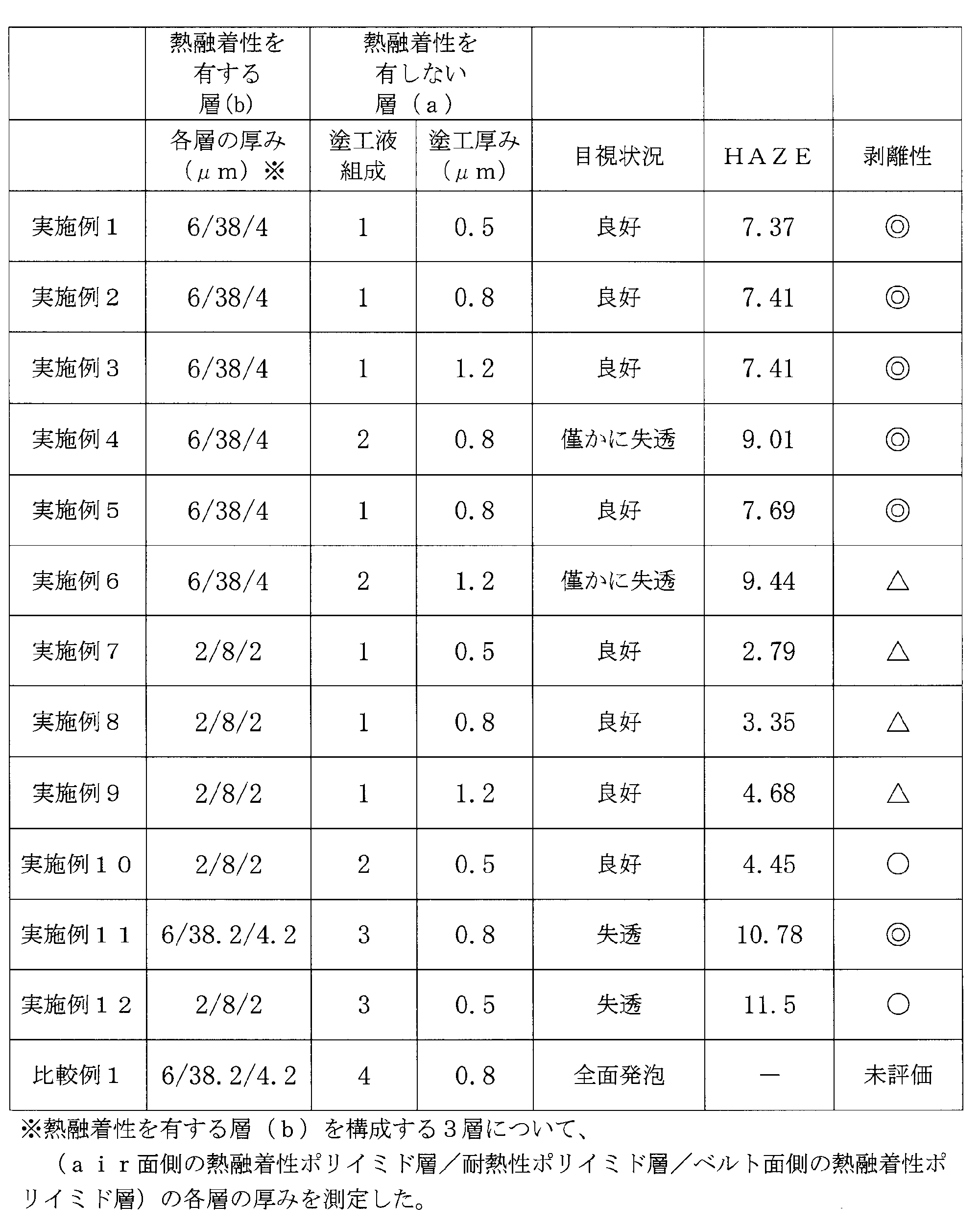

(1)熱融着性を有しない層(a)のテトラカルボン酸二無水物成分として2,3,3’,4’-ビフェニルテトラカルボン酸二無水物(a-BPDA)を用いた実施例では、フィルム表面の外観は良好であった。これに対して、a-BPDAを用いない比較例1においては、フィルム表面が発泡状態となった。a-BPDAがフィルム表面の外観に影響を及ぼすという事実は、全く新しい知見である。
(2)熱融着性を有しない層(a)のテトラカルボン酸二無水物成分中のa-BPDAが50モル%以上である場合、フィルム表面の外観は特に良好であった。
(3)熱融着性を有する層(b)の厚みが大きい場合の剥離性は、小さい場合のそれに比べて良好である。
12 熱融着性を有するポリイミド層(b)
12a 耐熱性ポリイミド層(S1)
12b 熱融着性を有するポリイミド層(S2)
13 熱融着性を有しない面
14 熱融着性を有する面
15 クランプ
16 ポリイミドフィルム
17 T剥離治具
Claims (9)
- ポリイミド層(b)と、
前記ポリイミド層(b)に接して積層されたポリイミド層(a)と、
を含むポリイミドフィルムであって、
前記ポリイミド層(b)のうちポリイミド層(a)と接していない面は熱融着性を有し、
前記ポリイミド層(a)のうちポリイミド層(b)と接していない面は熱融着性を有さず、
前記ポリイミド層(a)が、2,3,3’,4’-ビフェニルテトラカルボン酸二無水物を含むテトラカルボン酸成分と、ジアミン成分とから得られるポリイミドを含むことを特徴とする、ポリイミドフィルム。 - 前記ポリイミド層(b)が、熱融着性ポリイミド層と耐熱性ポリイミド層との多層構造を有することを特徴とする、請求項1に記載のポリイミドフィルム。
- 前記ポリイミド層(b)が、耐熱性ポリイミド層の両面に熱融着性ポリイミド層を有する3層構造であることを特徴とする、請求項1または2に記載のポリイミドフィルム。
- 前記テトラカルボン酸成分中の2,3,3’,4’-ビフェニルテトラカルボン酸二無水物の含有量が25モル%以上である請求項1から3のいずれか1項に記載のポリイミドフィルム。
- 前記テトラカルボン酸成分中の2,3,3’,4’-ビフェニルテトラカルボン酸二無水物の含有量が50モル%以上100モル%以下である請求項1から3のいずれか1項に記載のポリイミドフィルム。
- 前記ポリイミド層(b)の全体の厚みは15~50μmであり、前記耐熱性ポリイミド層の厚みは10~40μmであり、前記熱融着性ポリイミド層の単層の厚みは4~6μmである請求項2から5のいずれか1項に記載のポリイミドフィルム。
- 前記耐熱性ポリイミド層は、3,3’,4,4’-ビフェニルテトラカルボン酸二無水物を含む酸成分と、p-フェニレンジアミンを含むジアミン成分とから得られる請求項2から6のいずれか1項に記載のポリイミドフィルム。
- 請求項1~7のいずれか1項に記載のポリイミドフィルムのポリイミド層(b)のうち、ポリイミド層(a)層と接していない熱融着性を有する面と、金属層とが直接接して積層されているポリイミド金属積層板。
- 両面が熱融着性を有するポリイミド層(b)を得るためのポリアミック酸(b)を用いて自己支持性フィルム(b)を製造する工程と、
前記自己支持性フィルム(b)の片面のみに、2,3,3’,4’-ビフェニルテトラカルボン酸二無水物を含む酸成分とジアミン成分とから得られるポリアミック酸(a)を塗布し、塗布フィルムを製造する工程と、
前記塗布フィルムを加熱してイミド化する工程と
を含むことを特徴とする、ポリイミドフィルムの製造方法。
Priority Applications (4)
| Application Number | Priority Date | Filing Date | Title |
|---|---|---|---|
| US14/008,320 US20140023847A1 (en) | 2011-03-30 | 2012-03-28 | Polyimide film and metal laminate using same |
| JP2013507702A JP5904202B2 (ja) | 2011-03-30 | 2012-03-28 | ポリイミドフィルムおよびそれを用いた金属積層板 |
| CN201280021972.8A CN103502006B (zh) | 2011-03-30 | 2012-03-28 | 聚酰亚胺膜和使用其的金属层压体 |
| KR1020137028631A KR101917405B1 (ko) | 2011-03-30 | 2012-03-28 | 폴리이미드 필름 및 그것을 사용한 금속 적층판 |
Applications Claiming Priority (2)
| Application Number | Priority Date | Filing Date | Title |
|---|---|---|---|
| JP2011076875 | 2011-03-30 | ||
| JP2011-076875 | 2011-03-30 |
Publications (1)
| Publication Number | Publication Date |
|---|---|
| WO2012133594A1 true WO2012133594A1 (ja) | 2012-10-04 |
Family
ID=46931301
Family Applications (1)
| Application Number | Title | Priority Date | Filing Date |
|---|---|---|---|
| PCT/JP2012/058264 WO2012133594A1 (ja) | 2011-03-30 | 2012-03-28 | ポリイミドフィルムおよびそれを用いた金属積層板 |
Country Status (6)
| Country | Link |
|---|---|
| US (1) | US20140023847A1 (ja) |
| JP (1) | JP5904202B2 (ja) |
| KR (1) | KR101917405B1 (ja) |
| CN (1) | CN103502006B (ja) |
| TW (1) | TWI593550B (ja) |
| WO (1) | WO2012133594A1 (ja) |
Cited By (6)
| Publication number | Priority date | Publication date | Assignee | Title |
|---|---|---|---|---|
| WO2013157565A1 (ja) * | 2012-04-19 | 2013-10-24 | 宇部興産株式会社 | 熱融着性ポリイミドフィルム、熱融着性ポリイミドフィルムの製造方法及び熱融着性ポリイミドフィルムを用いたポリイミド金属積層体 |
| JP2014127716A (ja) * | 2012-12-26 | 2014-07-07 | Samsung Electro-Mechanics Co Ltd | コア基板及びその製造方法、並びに電子部品内蔵基板及びその製造方法 |
| EP2876129A1 (en) * | 2013-11-25 | 2015-05-27 | Samsung Electronics Co., Ltd | Composition for preparing polyimide, polyimide, and article including same |
| KR20150060551A (ko) * | 2013-11-25 | 2015-06-03 | 삼성전자주식회사 | 폴리이미드 제조용 조성물, 폴리이미드, 상기 폴리이미드를 포함하는 성형품, 및 상기 성형품을 포함하는 디스플레이 장치 |
| JP2020110972A (ja) * | 2019-01-11 | 2020-07-27 | エルジー・ケム・リミテッド | フィルム、金属張積層板、フレキシブル基板、フィルムの製造方法、金属張積層板の製造方法、及びフレキシブル基板の製造方法 |
| WO2023233878A1 (ja) * | 2022-05-31 | 2023-12-07 | 富士フイルム株式会社 | フィルム及び積層体 |
Families Citing this family (5)
| Publication number | Priority date | Publication date | Assignee | Title |
|---|---|---|---|---|
| WO2017069165A1 (ja) * | 2015-10-19 | 2017-04-27 | 宇部興産株式会社 | ポリイミド前駆体、架橋構造を有するポリイミドおよびその製造方法 |
| EP3276655A1 (en) * | 2016-07-26 | 2018-01-31 | Nederlandse Organisatie voor toegepast- natuurwetenschappelijk onderzoek TNO | Method and system for bonding a chip to a substrate |
| KR101966958B1 (ko) * | 2018-09-07 | 2019-04-09 | (주)아이피아이테크 | 반도체 패키지용 폴리이미드 필름 |
| CN109618429B (zh) * | 2018-11-27 | 2021-02-02 | 宁波今山电子材料有限公司 | 一种耐温在200-250℃的金属箔发热片的制备方法 |
| JP7124128B2 (ja) * | 2019-12-31 | 2022-08-23 | 深南電路股▲ふん▼有限公司 | プリント回路基板の製造方法及びプリント回路基板 |
Citations (4)
| Publication number | Priority date | Publication date | Assignee | Title |
|---|---|---|---|---|
| JPH02272078A (ja) * | 1989-04-13 | 1990-11-06 | Nitto Denko Corp | 耐熱性接着材料 |
| JPH10182820A (ja) * | 1996-10-29 | 1998-07-07 | Ube Ind Ltd | ポリイミド前駆体組成物及びポリイミド膜 |
| WO2008004496A1 (en) * | 2006-07-06 | 2008-01-10 | Toray Industries, Inc. | Thermoplastic polyimide, and laminated polyimide film and metal foil-laminated polyimide film using the thermoplastic polyimide |
| WO2009069797A1 (ja) * | 2007-11-29 | 2009-06-04 | Ube Industries, Ltd. | ポリアミック酸溶液の製造方法およびポリアミック酸溶液 |
Family Cites Families (8)
| Publication number | Priority date | Publication date | Assignee | Title |
|---|---|---|---|---|
| JPS61111359A (ja) * | 1984-11-06 | 1986-05-29 | Ube Ind Ltd | ポリイミド膜 |
| JPS62140822A (ja) * | 1985-12-17 | 1987-06-24 | Ube Ind Ltd | ポリイミド積層シ−トおよびその製造法 |
| EP0459452A3 (en) * | 1990-05-30 | 1992-04-08 | Ube Industries, Ltd. | Aromatic polyimide film laminated with metal foil |
| JP2000096010A (ja) * | 1998-09-22 | 2000-04-04 | Toray Ind Inc | 半導体装置用接着テープ |
| JP4508441B2 (ja) * | 2001-02-16 | 2010-07-21 | 新日鐵化学株式会社 | 積層体及びその製造方法 |
| JP2004315601A (ja) * | 2003-04-14 | 2004-11-11 | Ube Ind Ltd | 接着性の改良されたポリイミドフィルム、その製造法および積層体 |
| JP4736703B2 (ja) * | 2005-10-14 | 2011-07-27 | 宇部興産株式会社 | 銅配線ポリイミドフィルムの製造方法 |
| TWI454375B (zh) * | 2008-03-06 | 2014-10-01 | Nippon Steel & Sumikin Chem Co | Laminates for flexible substrates and thermally conductive polyimide films |
-
2012
- 2012-03-28 JP JP2013507702A patent/JP5904202B2/ja active Active
- 2012-03-28 CN CN201280021972.8A patent/CN103502006B/zh active Active
- 2012-03-28 US US14/008,320 patent/US20140023847A1/en active Pending
- 2012-03-28 WO PCT/JP2012/058264 patent/WO2012133594A1/ja active Application Filing
- 2012-03-28 KR KR1020137028631A patent/KR101917405B1/ko active IP Right Grant
- 2012-03-30 TW TW101111448A patent/TWI593550B/zh active
Patent Citations (4)
| Publication number | Priority date | Publication date | Assignee | Title |
|---|---|---|---|---|
| JPH02272078A (ja) * | 1989-04-13 | 1990-11-06 | Nitto Denko Corp | 耐熱性接着材料 |
| JPH10182820A (ja) * | 1996-10-29 | 1998-07-07 | Ube Ind Ltd | ポリイミド前駆体組成物及びポリイミド膜 |
| WO2008004496A1 (en) * | 2006-07-06 | 2008-01-10 | Toray Industries, Inc. | Thermoplastic polyimide, and laminated polyimide film and metal foil-laminated polyimide film using the thermoplastic polyimide |
| WO2009069797A1 (ja) * | 2007-11-29 | 2009-06-04 | Ube Industries, Ltd. | ポリアミック酸溶液の製造方法およびポリアミック酸溶液 |
Cited By (10)
| Publication number | Priority date | Publication date | Assignee | Title |
|---|---|---|---|---|
| WO2013157565A1 (ja) * | 2012-04-19 | 2013-10-24 | 宇部興産株式会社 | 熱融着性ポリイミドフィルム、熱融着性ポリイミドフィルムの製造方法及び熱融着性ポリイミドフィルムを用いたポリイミド金属積層体 |
| JP2014127716A (ja) * | 2012-12-26 | 2014-07-07 | Samsung Electro-Mechanics Co Ltd | コア基板及びその製造方法、並びに電子部品内蔵基板及びその製造方法 |
| EP2876129A1 (en) * | 2013-11-25 | 2015-05-27 | Samsung Electronics Co., Ltd | Composition for preparing polyimide, polyimide, and article including same |
| KR20150060551A (ko) * | 2013-11-25 | 2015-06-03 | 삼성전자주식회사 | 폴리이미드 제조용 조성물, 폴리이미드, 상기 폴리이미드를 포함하는 성형품, 및 상기 성형품을 포함하는 디스플레이 장치 |
| JP2015101729A (ja) * | 2013-11-25 | 2015-06-04 | 三星電子株式会社Samsung Electronics Co.,Ltd. | ポリイミド製造用組成物、ポリイミド、該ポリイミドを含む成形品、および該成形品を含む光学装置 |
| US10100151B2 (en) | 2013-11-25 | 2018-10-16 | Samsung Electronics Co., Ltd. | Composition for preparing polyimide, polyimide, and article including same |
| KR102276288B1 (ko) | 2013-11-25 | 2021-07-12 | 삼성전자주식회사 | 폴리이미드 제조용 조성물, 폴리이미드, 상기 폴리이미드를 포함하는 성형품, 및 상기 성형품을 포함하는 디스플레이 장치 |
| JP2020110972A (ja) * | 2019-01-11 | 2020-07-27 | エルジー・ケム・リミテッド | フィルム、金属張積層板、フレキシブル基板、フィルムの製造方法、金属張積層板の製造方法、及びフレキシブル基板の製造方法 |
| JP7195530B2 (ja) | 2019-01-11 | 2022-12-26 | エルジー・ケム・リミテッド | フィルム、金属張積層板、フレキシブル基板、フィルムの製造方法、金属張積層板の製造方法、及びフレキシブル基板の製造方法 |
| WO2023233878A1 (ja) * | 2022-05-31 | 2023-12-07 | 富士フイルム株式会社 | フィルム及び積層体 |
Also Published As
| Publication number | Publication date |
|---|---|
| US20140023847A1 (en) | 2014-01-23 |
| KR101917405B1 (ko) | 2018-11-09 |
| JP5904202B2 (ja) | 2016-04-13 |
| TWI593550B (zh) | 2017-08-01 |
| CN103502006B (zh) | 2016-02-10 |
| TW201244922A (en) | 2012-11-16 |
| CN103502006A (zh) | 2014-01-08 |
| JPWO2012133594A1 (ja) | 2014-07-28 |
| KR20140027197A (ko) | 2014-03-06 |
Similar Documents
| Publication | Publication Date | Title |
|---|---|---|
| JP5904202B2 (ja) | ポリイミドフィルムおよびそれを用いた金属積層板 | |
| JP4147639B2 (ja) | フレキシブル金属箔積層体 | |
| KR101076505B1 (ko) | 접착 필름 및 그의 이용 | |
| JP5880561B2 (ja) | ポリイミド金属積層体の製造方法 | |
| JP2006188025A (ja) | 銅張積層板 | |
| JP3938058B2 (ja) | 熱融着性を有するポリイミドフィルム、それを用いた積層板およびそれらの製造法 | |
| JP2001270034A (ja) | フレキシブル金属箔積層体 | |
| JPWO2016136897A1 (ja) | 銅張積層板の製造方法 | |
| JP5382274B2 (ja) | 熱融着性ポリイミドフィルム及びその製造方法、熱融着性ポリイミドフィルムを用いたポリイミド金属積層体 | |
| WO2013157565A1 (ja) | 熱融着性ポリイミドフィルム、熱融着性ポリイミドフィルムの製造方法及び熱融着性ポリイミドフィルムを用いたポリイミド金属積層体 | |
| JP5040451B2 (ja) | 離型材と片面金属箔積層樹脂フィルムとの積層体の製造方法、片面金属箔積層フィルム | |
| JP4389338B2 (ja) | フレキシブル金属箔積層体の製造法 | |
| JP5711989B2 (ja) | ポリイミド系多層フィルムの製造方法 | |
| JP2015129200A (ja) | 熱融着性ポリイミドフィルム、及びそれを用いたポリイミド金属積層体 | |
| JP2003192789A (ja) | 熱融着性ポリイミドおよび該ポリイミドを使用した積層体 | |
| JP2005131919A (ja) | フレキシブル金属箔積層体 | |
| JP2001179911A (ja) | 耐熱性樹脂ボ−ド及びその製造法 | |
| JP4389337B2 (ja) | フレキシブル金属箔積層体及びその製造法 | |
| JP4345187B2 (ja) | フレキシブル金属箔積層体の製造方法 | |
| JP4821411B2 (ja) | 片面のみに熱融着性を有するポリイミドフィルム、片面銅張り積層板 | |
| JP4360025B2 (ja) | 補強材を有するポリイミド片面積層体およびその製造法 | |
| JP4415950B2 (ja) | フレキシブル金属箔積層体の製造方法 | |
| JP2013204017A (ja) | 熱融着性ポリイミドフィルム、及びそれを用いたポリイミド金属積層体 | |
| JP2006199871A (ja) | 接着フィルム | |
| JP2007216687A (ja) | 銅張積層板の製造方法、電子部品用基板の製造方法 |
Legal Events
| Date | Code | Title | Description |
|---|---|---|---|
| 121 | Ep: the epo has been informed by wipo that ep was designated in this application |
Ref document number: 12763966 Country of ref document: EP Kind code of ref document: A1 |
|
| ENP | Entry into the national phase |
Ref document number: 2013507702 Country of ref document: JP Kind code of ref document: A |
|
| WWE | Wipo information: entry into national phase |
Ref document number: 14008320 Country of ref document: US |
|
| NENP | Non-entry into the national phase |
Ref country code: DE |
|
| ENP | Entry into the national phase |
Ref document number: 20137028631 Country of ref document: KR Kind code of ref document: A |
|
| 122 | Ep: pct application non-entry in european phase |
Ref document number: 12763966 Country of ref document: EP Kind code of ref document: A1 |