WO2012077663A1 - 位相差フィルム、偏光板、および表示パネル装置 - Google Patents
位相差フィルム、偏光板、および表示パネル装置 Download PDFInfo
- Publication number
- WO2012077663A1 WO2012077663A1 PCT/JP2011/078149 JP2011078149W WO2012077663A1 WO 2012077663 A1 WO2012077663 A1 WO 2012077663A1 JP 2011078149 W JP2011078149 W JP 2011078149W WO 2012077663 A1 WO2012077663 A1 WO 2012077663A1
- Authority
- WO
- WIPO (PCT)
- Prior art keywords
- film
- retardation film
- retardation
- group
- polymer
- Prior art date
Links
Images
Classifications
-
- G—PHYSICS
- G02—OPTICS
- G02B—OPTICAL ELEMENTS, SYSTEMS OR APPARATUS
- G02B5/00—Optical elements other than lenses
- G02B5/30—Polarising elements
- G02B5/3025—Polarisers, i.e. arrangements capable of producing a definite output polarisation state from an unpolarised input state
-
- C—CHEMISTRY; METALLURGY
- C08—ORGANIC MACROMOLECULAR COMPOUNDS; THEIR PREPARATION OR CHEMICAL WORKING-UP; COMPOSITIONS BASED THEREON
- C08J—WORKING-UP; GENERAL PROCESSES OF COMPOUNDING; AFTER-TREATMENT NOT COVERED BY SUBCLASSES C08B, C08C, C08F, C08G or C08H
- C08J5/00—Manufacture of articles or shaped materials containing macromolecular substances
- C08J5/18—Manufacture of films or sheets
-
- G—PHYSICS
- G02—OPTICS
- G02B—OPTICAL ELEMENTS, SYSTEMS OR APPARATUS
- G02B27/00—Optical systems or apparatus not provided for by any of the groups G02B1/00 - G02B26/00, G02B30/00
- G02B27/28—Optical systems or apparatus not provided for by any of the groups G02B1/00 - G02B26/00, G02B30/00 for polarising
- G02B27/286—Optical systems or apparatus not provided for by any of the groups G02B1/00 - G02B26/00, G02B30/00 for polarising for controlling or changing the state of polarisation, e.g. transforming one polarisation state into another
-
- G—PHYSICS
- G02—OPTICS
- G02B—OPTICAL ELEMENTS, SYSTEMS OR APPARATUS
- G02B5/00—Optical elements other than lenses
- G02B5/30—Polarising elements
- G02B5/3083—Birefringent or phase retarding elements
-
- H—ELECTRICITY
- H10—SEMICONDUCTOR DEVICES; ELECTRIC SOLID-STATE DEVICES NOT OTHERWISE PROVIDED FOR
- H10K—ORGANIC ELECTRIC SOLID-STATE DEVICES
- H10K50/00—Organic light-emitting devices
- H10K50/80—Constructional details
- H10K50/86—Arrangements for improving contrast, e.g. preventing reflection of ambient light
-
- H—ELECTRICITY
- H10—SEMICONDUCTOR DEVICES; ELECTRIC SOLID-STATE DEVICES NOT OTHERWISE PROVIDED FOR
- H10K—ORGANIC ELECTRIC SOLID-STATE DEVICES
- H10K59/00—Integrated devices, or assemblies of multiple devices, comprising at least one organic light-emitting element covered by group H10K50/00
- H10K59/50—OLEDs integrated with light modulating elements, e.g. with electrochromic elements, photochromic elements or liquid crystal elements
-
- G—PHYSICS
- G02—OPTICS
- G02B—OPTICAL ELEMENTS, SYSTEMS OR APPARATUS
- G02B1/00—Optical elements characterised by the material of which they are made; Optical coatings for optical elements
- G02B1/10—Optical coatings produced by application to, or surface treatment of, optical elements
- G02B1/11—Anti-reflection coatings
Definitions
- the present invention relates to a retardation film including a stretched polymer film.
- the film Apart from the performance of the film, it is necessary to mass-produce a wide and thin film in order to cope with an increase in the size and thickness of the display and an increase in production volume.
- the strength of the film is an important design parameter in terms of runnability, workability, and product reliability.
- a circularly polarizing plate having a ⁇ / 4 retardation plate is used for the organic EL display for preventing reflection.
- an inverse wavelength dispersion type retardation plate is required.
- a thin ⁇ / 4 retardation plate with a reverse wavelength dispersion type is required to be wide. .
- the film tends to become brittle. For this reason, the stretchability is also poor, and it is difficult to design for thinning and enlargement.
- a retardation film as one of optical films.
- a film having a characteristic that the retardation value is larger as measured with light having a longer wavelength also referred to as reverse wavelength dispersion characteristic
- these documents do not discuss improvement of the brittleness of the film as described above.
- the present invention has been made to solve such problems, and an object thereof is to provide a retardation film excellent in running property, workability, and product reliability.
- the present invention is based on the knowledge that the strength such as the bending strength of the stretched polymer film constituting the retardation film can be evaluated using a value indicating the optical properties of the retardation film. It was made.
- the retardation film of the present invention is a retardation film including a stretched polymer film, and is represented by the following formulas (1) to (3): 0.70 ⁇ Re [450] / Re [550] ⁇ 0.97 (1) 1.5 ⁇ 10 ⁇ 3 ⁇ n ⁇ 6 ⁇ 10 ⁇ 3 (2) 1.13 ⁇ NZ ⁇ 1.50 (3) (In the formula, Re [450] and Re [550] are in-plane retardation values of the retardation film measured with light having a wavelength of 450 nm and 550 nm at 23 ° C., respectively, and ⁇ n is the retardation of the retardation film.
- nx-ny when the refractive indexes in the axial direction and the fast axis direction are nx and ny, respectively
- NZ is the refractive index in the thickness direction of the retardation film. This is a ratio of nx-nz, which is birefringence in the thickness direction, and nx-ny, which is in-plane birefringence.
- the absolute value (m 2 / N) of the photoelastic coefficient of the retardation film measured with light having a wavelength of 550 nm at 23 ° C. is 50 ⁇ 10 ⁇ 12 or less.
- the absolute value (m 2 / N) of the photoelastic coefficient of the retardation film measured with light having a wavelength of 550 nm at 23 ° C. is 10 ⁇ 10 ⁇ 12 to 45 ⁇ 10 ⁇ 12 .
- the polymer film made of, for example, a copolymer is an aliphatic polymer and has a main chain having stretch orientation and a unit having an absorption edge at 260 to 380 nm in the side chain, and A polymer film containing as a main component a high molecular weight body in which the surface of the side chain intersects the direction in which the main chain extends.
- a polarizing plate is provided.
- This polarizing plate has at least the retardation film and a polarizer.
- the polarizing plate is a circular polarizing plate.
- a display panel device is provided.
- This display panel device has at least the polarizing plate.
- the retardation film of the present invention has the formula 0.7 ⁇ Re [450] / Re [550] ⁇ 0.97 (1) 1.5 ⁇ 10 ⁇ 3 ⁇ n ⁇ 6 ⁇ 10 ⁇ 3 (2) 1.13 ⁇ NZ ⁇ 1.50 (3)
- Re [450] and Re [550] are in-plane retardation values of the retardation film measured with light having a wavelength of 450 nm and 550 nm at 23 ° C., respectively, and ⁇ n is the retardation of the retardation film.
- NZ is the refractive index in the thickness direction of the retardation film. It is excellent in running property, workability and product reliability while exhibiting reverse wavelength dispersion characteristics by satisfying the ratio of thickness direction birefringence nx-nz to in-plane birefringence nx-ny. .
- the retardation film having such characteristics is extremely useful for improving the production efficiency of the retardation film and the display characteristics of the display panel device.
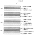
- FIG. 1 it is a schematic sectional drawing of the polarizing plate using retardation film.
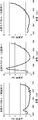
- FIG. 1 It is a schematic diagram which shows the concept of the typical manufacturing process of the polarizer used for this invention. It is a graph which shows the reflection spectrum of the display panel apparatus provided with the polarizing plate using the retardation film obtained by Example 1, the comparative example 1, and the comparative example 2.
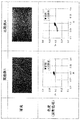
- FIG. It is the photograph and chromaticity diagram which show the heating test result of the display panel apparatus provided with the polarizing plate using the retardation film obtained in Example 1 and Comparative Example 4.
- the retardation film of the present invention is obtained by stretching a polymer film.
- the retardation film refers to one having birefringence in the plane and / or in the thickness direction.
- Re [550] means an in-plane retardation value measured with light having a wavelength of 550 nm at 23 ° C.
- the slow axis means the direction in which the in-plane refractive index is maximum.
- the in-plane birefringence ⁇ n which is nx-ny of the present invention is preferably 1.5 ⁇ 10 ⁇ 3 to 6 ⁇ 10 ⁇ 3 , more preferably 1.5 ⁇ 10 ⁇ 3 to 5 ⁇ 10 ⁇ 3 . More preferably, it is 2.0 ⁇ 10 ⁇ 3 to 4.5 ⁇ 10 ⁇ 3 .
- the ⁇ n is preferably 3.5 ⁇ 10 ⁇ 3 .
- the stretching step in the production of the retardation film includes a fixed-end stretching, for example, a lateral stretching step or an oblique stretching step, and ⁇ n is set in the above range by adjusting the stretching ratio, stretching temperature, stretching speed, and the like.
- ⁇ n is within this range, it is easy to design the retardation film to be very thin, and it is easy to incorporate it into a thin display device.
- ⁇ n is smaller than this range, it is necessary to excessively increase the thickness of the film.
- the retardation film preferably has an in-plane retardation value (Re [550]) measured with light having a wavelength of 550 nm and an in-plane retardation value (Re [450] measured with light having a wavelength of 450 nm at 23 ° C. ]).
- Re [550] in-plane retardation value measured with light having a wavelength of 550 nm
- Re [450] measured with light having a wavelength of 450 nm at 23 ° C. ]
- the retardation film having such wavelength dispersion characteristics if the ratio is within this range, the longer the wavelength, the greater the retardation, and the ideal retardation characteristics can be obtained at each wavelength in the visible region.
- a retardation film having such a wavelength dependency is prepared as a 1 ⁇ 4 ⁇ plate, and a circularly polarizing plate or the like can be prepared by bonding to a polarizing plate.
- the ratio of Re [550] to Re [450] (Re [450] / Re [550]) of the retardation film is preferably less than 1, more preferably 0.50 to 0.99, and particularly preferably. Is 0.70 to 0.97, and most preferably 0.75 to 0.95.
- the retardation film preferably has an in-plane retardation value (Re [550]) measured with light having a wavelength of 550 nm and an in-plane retardation value (Re [650] measured with light having a wavelength of 650 nm at 23 ° C. ]) Smaller than.
- a retardation film having such a wavelength dispersion characteristic has a constant retardation value in a red region. For example, when used in a liquid crystal display device, a phenomenon in which light leaks depending on a viewing angle or a display image is red. It is possible to improve a taste-taking phenomenon (also referred to as a red-ish phenomenon).
- the ratio of Re [550] and Re [650] (Re [650] / Re [550]) of the retardation film is preferably greater than 1, more preferably 1.01-1.20, and particularly preferably. Is 1.02 to 1.15.
- Rth refers to a retardation value in the thickness direction.
- the slow axis means the direction in which the in-plane refractive index is maximum.
- the Rth can be appropriately selected depending on the purpose.
- the Rth is 10 nm or more, preferably 50 nm to 500 nm.
- the Rth is preferably 200 nm to 400 nm, more preferably 250 nm to 290 nm.
- the Rth is preferably 100 nm to 200 nm, more preferably 130 nm to 150 nm.
- Re [450], Re [550], and Re [650] can be measured using the product name “AxoScan” manufactured by Axometrics.
- NZ refers to the ratio of nx-nz, which is birefringence in the thickness direction, and nx-ny, which is in-plane birefringence (also referred to as Nz coefficient).
- NZ of the retardation film of the present invention is 1.13 to 1.50. Preferably, it is 1.14 to 1.40.
- the stretching step in the production of the retardation film includes a fixed-end stretching, for example, a lateral stretching step or an oblique stretching step, and NZ is set in the above range by adjusting the stretching ratio, stretching temperature, stretching speed, and the like.
- the bending strength (flexibility) of the retardation film can be remarkably improved.
- film forming conditions such as temperature, speed, thickness, and the like may be appropriately changed.
- the folding strength in the longitudinal direction of the film, which is the stretching direction becomes strong, but the folding strength in the width direction becomes very weak.
- a state in which a force for regulating the width is generated in an angular direction intersecting the stretching direction (for example, in the case of lateral uniaxial stretching, in a direction perpendicular to the width direction of the film which is the stretching direction).
- the molecules can be oriented not only in the stretching direction but also in the angular direction intersecting with the stretching direction.
- the refractive index relationship can be nx> ny> nz.
- the folding strength in the stretching direction and the folding strength in the width direction can be compatible at a high level.
- the transmittance of the retardation film is preferably 80% or more, more preferably 85% or more, and particularly preferably 90% or more.
- the absolute value of the photoelastic coefficient at 23 ° C. of the retardation film; C (m 2 / N) is 50 ⁇ 10 ⁇ 12 or less. Due to the shrinkage stress of the polarizer, the heat of the display panel, and the surrounding environment (moisture and heat resistance), the retardation film is forced and the resulting change in retardation value can be prevented. A display panel device having excellent display uniformity can be obtained.
- C of the retardation film is 10 ⁇ 10 ⁇ 12 to 45 ⁇ 10 ⁇ 12 , particularly preferably 3 ⁇ 10 ⁇ 12 to 40 ⁇ 10 ⁇ 12 or less.
- the retardation film of the present invention is produced by orienting by stretching a polymer film.
- any appropriate stretching method can be adopted depending on the purpose.
- the stretching method suitable for the present invention include a transverse uniaxial stretching method, a longitudinal and transverse simultaneous biaxial stretching method, and a longitudinal and transverse sequential biaxial stretching method.
- any suitable stretching machine such as a tenter stretching machine or a biaxial stretching machine can be used.
- the stretching machine includes a temperature control unit. When extending
- the stretching direction is preferably stretched in the film width direction (TD direction) or in an oblique direction.
- the temperature at which the polymer film is stretched can be appropriately selected depending on the purpose.
- the stretching is performed in the range of Tg ⁇ 20 ° C. to Tg + 30 ° C. with respect to the glass transition temperature (Tg) of the polymer film.
- Tg glass transition temperature
- the stretching temperature is 90 ° C. to 210 ° C., more preferably 100 ° C. to 200 ° C., and particularly preferably 100 ° C. to 180 ° C.
- the glass transition temperature can be obtained by a DSC method according to JIS K 7121 (1987).
- any appropriate means can be adopted as means for controlling the stretching temperature.
- the temperature control means include an air circulation type thermostatic oven in which hot air or cold air circulates, a heater using microwaves or far infrared rays, a roll heated for temperature adjustment, a heat pipe roll, a metal belt, and the like. .
- Magnification ratio (stretch ratio) for stretching the polymer film can be appropriately selected according to the purpose.
- the draw ratio is preferably more than 1 and 6 times or less, more preferably more than 1.5 times and 4 times or less, and particularly preferably more than 2.0 times and 3 times or less.
- the feeding speed at the time of stretching is not particularly limited, but is preferably 0.5 m / min to 30 m / min, more preferably 1 m / min to 20 m / min from the viewpoint of mechanical accuracy and stability. If it is said extending
- the retardation film of the present invention can be used for any appropriate application. Typical applications include ⁇ / 4 plates, ⁇ / 2 plates, and optical compensation films for liquid crystal display devices. In addition, an antireflection film for flat panel displays such as a liquid crystal display device, an organic EL display, and a plasma display can be used.
- a stretched polymer film having a thermoplastic resin as a main component is used.
- an aliphatic polymer composed of a copolymer and having a main chain having stretch orientation and a unit having an absorption end at 260 to 380 nm in the side chain and with respect to the direction in which the main chain extends is used.
- a cellulose resin polyester, polyvinyl alcohol, polyvinyl acetal, polycarbonate, polyamide, polyimide, polyethersulfone, polyether, polysulfone, polystyrene, polynorbornene, polyolefin , Acrylic resin, urethane resin, acrylic urethane resin, transparent resin such as acetate resin, etc., segments that create a rigid ring structure or crystalline structure that is long in the main chain direction are introduced, and the absorption edge wavelength is A stretched polymer film mainly composed of a high molecular weight substance having an aromatic group having a side chain of 260 nm to 380 nm is used. In this high molecular weight product, the segment and aromatic group may be copolymerized or blended.
- the reverse wavelength dispersion characteristic as shown in the formula (1) of claim 1 it is only necessary to have a unit that makes the wavelength dispersion steep as a side chain.
- the chain may have at least one aromatic group.
- the absorption edge wavelength is larger than 380 nm, it enters the visible region, causing problems such as coloring.
- the wavelength is shorter than 260 nm, the dispersion of the side chain approaches a flat dispersion, so that the wavelength dispersibility of the high molecular weight substance becomes loose.
- the side chain has an aromatic group having an absorption edge wavelength of 260 nm to 380 nm, the wavelength dependence of the birefringence of the side chain becomes steep without causing problems such as coloring, and as a whole high molecular weight product. It is considered that the reverse wavelength dispersion characteristic is efficiently exhibited.
- the photoelastic coefficient is attributed to the aromaticity of the material structure, and is low in the alicyclic COP system (cycloolefin system) and high in the aromatic PC (polycarbonate) system. Therefore, in order to lower the photoelastic coefficient, it is sufficient to increase the aliphaticity of the polymer, but the orientation is lowered as a trade-off. Therefore, in order to realize a high orientation as shown in the formula (2) of claim 1, a highly oriented structure in the aliphatic polymer, specifically, a rigid ring structure long in the main chain direction It is conceivable to introduce a segment that forms a crystalline structure. In addition, the orientation of a high molecular weight body becomes larger when it has a side chain component having an absorption wavelength on the longer wavelength side.
- stretched film means a plastic in which tension is applied to an unstretched film at an appropriate temperature, or tension is further applied to a previously stretched film to increase molecular orientation in a specific direction. Say film.
- the retardation film of the present invention contains a polymer having at least a repeating unit represented by the following general formula (I).
- the polymer can be obtained, for example, by subjecting at least two kinds of aldehyde compounds and / or ketone compounds to a polyvinyl alcohol resin.
- the arrangement order of each basic unit of l, m, n, and o is not particularly limited, and may be any of alternating, random, or block.
- R 1 , A and B are each independently a hydrogen atom, a halogen atom, a straight or branched alkyl group having 1 to 4 carbon atoms, or a straight chain having 1 to 4 carbon atoms.
- a branched halogenated alkyl group, a linear or branched alkoxy group having 1 to 4 carbon atoms, an alkoxycarbonyl group, an acyloxy group, an amino group, an azide group, a nitro group, a cyano group or a hydroxyl group provided that R 1 is not a hydrogen atom).
- R 1 is a substituent substituted at the 2-position of the naphthyl ring, and A is a substituent substituted at the 3-position or 4-position of the naphthyl ring. B is a substituent substituted from the 5-position to the 8-position of the naphthyl ring.
- R 1 is a methoxy group.
- a and B are hydrogen atoms.
- R 1 is used to control the conformation of the naphthyl ring to which the substituent is bonded. More specifically, the substituent is presumed to be easily conformed between two oxygen atoms in the general formula (I) due to steric hindrance.
- the planar structure of the naphthyl ring is oriented substantially perpendicular to the imaginary line connecting the two oxygen atoms.
- the basic unit; l can be obtained, for example, by a condensation reaction of a polyvinyl alcohol resin with 1-naphthaldehydes or 1-naphthones.
- 1-naphthaldehydes appropriate ones can be adopted as appropriate.
- the 1-naphthaldehydes include 2-methoxy-1-naphthaldehyde, 2-ethoxy-1-naphthaldehyde, 2-propoxy-1-naphthaldehyde, 2-methyl-1-naphthaldehyde, 2-hydroxy Examples include 1-naphthaldehyde.
- the 1-naphthones appropriate ones can be adopted as appropriate.
- Examples of the 1-naphthones include 2-hydroxy-1-acetonaphthone and 8′-hydroxy-1′-benzonaphthone.
- 2-methoxy-1-naphthaldehyde is preferable (in this case, in the above general formula (I), R 1 is a methoxy group, and A and B are hydrogen atoms).
- the 1-naphthaldehydes can be obtained by any appropriate synthesis method.
- a method for synthesizing the 1-naphthaldehydes for example, substituted or unsubstituted naphthoic acid as described in JP-A-9-040600 and JP-A-9-110775 can be used with any alcohol. Examples include a method in which a substituted or unsubstituted naphthoic acid ester is reacted to reduce it with a reducing agent such as diisobutylaluminum hydride or sodium bis (2-methoxyethoxy) aluminum hydride. Commercially available 1-naphthaldehydes can also be used as they are.
- the above 1-naphthones can be obtained by any appropriate synthesis method.
- a method for synthesizing the 1-naphthones for example, substituted or unsubstituted naphthoic acid is reacted with an appropriate phosphoric acid halide or thionyl chloride to form an acyl halide, and this is further subjected to an appropriate nucleophilicity.
- the method of making it react with a reagent is mentioned.
- the method described in Reference Example 1 of Japanese Patent No. 2846418 can also be used.
- R 2 represents a hydrogen atom, a linear or branched alkyl group having 1 to 4 carbon atoms, a substituted or unsubstituted cycloalkyl group having 5 to 10 carbon atoms, or substituted or unsubstituted phenyl.
- a polymer in which such a substituent is introduced into R 2 is excellent in solubility in a general-purpose solvent (for example, acetone, ethyl acetate, toluene, etc.).
- R 2 is a linear or branched alkyl group having 1 to 4 carbon atoms.
- the basic unit; m can be obtained, for example, by a condensation reaction between a polyvinyl alcohol resin and an arbitrary aldehyde compound or ketone compound.
- aldehyde compounds include formaldehyde, acetaldehyde, 1,1-diethoxyethane (acetal), propionaldehyde, n-butyraldehyde, isobutyraldehyde, cyclohexane carboxaldehyde, 5-norbornene-2-carboxaldehyde, and 3-cyclohexene-1- Carboxaldehyde, dimethyl-3-cyclohexene-1-carboxaldehyde, benzaldehyde, 2-chlorobenzaldehyde, p-dimethylaminobenzaldehyde, t-butylbenzaldehyde, 3,4-dimethoxybenzaldehyde, 2-nitrobenzaldehyde, 4-
- ketone compound examples include acetone, ethyl methyl ketone, diethyl ketone, t-butyl ketone, dipropyl ketone, allyl ethyl ketone, acetophenone, p-methylacetophenone, 4′-aminoacetophenone, p-chloroacetophenone, 4′-methoxyacetophenone, 2'-hydroxyacetophenone, 3'-nitroacetophenone, P- (1-piperidino) acetophenone, benzalacetophenone, propiophenone, benzophenone, 4-nitrobenzophenone, 2-methylbenzophenone, p-bromobenzophenone, cyclohexyl (phenyl) Examples include methanone, 2-butyronaphthone, and 1-acetonaphthone.
- R 3 represents a hydrogen atom, a linear or branched alkyl group having 1 to 4 carbon atoms, a benzyl group, a silyl group, a phosphate group, an acyl group, a benzoyl group, or a sulfonyl group.
- R 3 is used to adjust the water absorption rate to an appropriate value by protecting the remaining hydroxyl groups (also referred to as end cap treatment).
- end cap treatment When the water absorption is reduced, for example, when the polymer is used as a retardation film, a film having high transparency and excellent retardation stability can be obtained.
- the substituent may not be end-capped (that is, R 3 may remain a hydrogen atom).
- any suitable group typically, which can be end-capped
- any suitable group typically, which can be end-capped that can react with the hydroxyl group to form a substituent (that is, can be end-capped) Protecting groups
- protecting group examples include benzyl group, 4-methoxyphenylmethyl group, methoxymethyl group, trimethylsilyl group, triethylsilyl group, t-butyldimethylsilyl group, acetyl group, benzoyl group, methanesulfonyl group, bis-4-nitro. And phenyl phosphite.
- R 3 is preferably a trimethylsilyl group, a triethylsilyl group, or a t-butyldimethylsilyl group.
- reaction conditions for the above-mentioned end cap treatment can be appropriately selected depending on the type of substituent to be reacted with a hydroxyl group.
- reactions such as alkylation, benzylation, silylation, phosphorylation, and sulfonylation are carried out by converting a polymer having a remaining hydroxyl group and a chloride of a desired substituent into 4 (N, N-dimethylamino) pyridine and the like.
- stirring can be performed at 25 to 100 ° C. for 1 to 20 hours.
- the basic unit; o can be introduced using, for example, a substituted or unsubstituted benzaldehyde as an aldehyde compound.
- a substituted or unsubstituted benzaldehyde as an aldehyde compound.
- R 4 represents a hydrogen atom, a halogen atom, a linear or branched alkyl group having 1 to 4 carbon atoms, a linear or branched halogenated alkyl group having 1 to 4 carbon atoms, A linear or branched alkoxy group having 1 to 4 carbon atoms, an alkoxycarbonyl group, an acyloxy group, an amino group, a nitro group, a cyano group, or a hydroxyl group is represented.
- R 4 is a substituent substituted at the ortho, meta or para position of the benzene ring.
- the ratio of the basic units l, m, n, and o can be appropriately selected according to the purpose.
- the ratio of the above basic unit; l is preferably 1 mol% to 20 mol%, more preferably 5 mol% to 15 mol%.
- the ratio of the basic unit; m is preferably 25 mol% to 50 mol%, more preferably 30 mol% to 50 mol%.
- the ratio of the basic unit; n is preferably 10 mol% to 55 mol%, more preferably 15 mol% to 50 mol%.
- the ratio of the basic unit; o is preferably 1 mol% to 20 mol%, more preferably 5 mol% to 15 mol%.
- the ratio [l / (m + o)] (mol / mol) of the structural unit 1 and the total of the structural units m and o is preferably 0.10 to 0.50, more preferably 0.12 to 0.40, particularly preferably 0.15 to 0.30.
- the retardation film containing the polymer has transparency, retardation development property, and reverse wavelength dispersion characteristics. Show excellent properties.
- the weight average molecular weight of the polymer is preferably 1,000 to 1,000,000, more preferably 3,000 to 500,000, and particularly preferably 5,000 to 300,000. By setting the weight average molecular weight within the above range, a so-called retardation film having excellent mechanical strength can be obtained.
- the weight average molecular weight can be calculated from polystyrene as a standard sample by gel permeation chromatograph (GPC) method.
- the analyzer is “HLC-8120GPC” manufactured by TOSOH (column: TSKgel SuperHM-H / H4000 / H3000 / H2000, column size: 6.0 mm ID ⁇ 150 mm each, eluent: tetrahydrofuran, flow rate: 0.6 ml / min, detector: RI, column temperature: 40 ° C., injection amount: 20 ⁇ l).
- the glass transition temperature of the above polymer is preferably 90 ° C. to 190 ° C., more preferably 100 ° C. to 170 ° C., and particularly preferably 110 ° C. to 160 ° C. By setting the glass transition temperature in the above range, a so-called retardation film having excellent heat resistance can be obtained.
- the glass transition temperature can be obtained by a DSC method according to JIS K 7121 (1987).
- the polymer film containing the polymer may further contain any appropriate additive.
- the additive include a plasticizer, a heat stabilizer, a light stabilizer, a lubricant, an antioxidant, an ultraviolet absorber, a flame retardant, an antistatic agent, a compatibilizer, a crosslinking agent, and a thickener. It is done.
- the amount of the additive used can be appropriately selected depending on the purpose.
- the amount of the additive used is preferably more than 0 and 10 (weight ratio) or less, and more preferably more than 0 and 5 (weight ratio) or less with respect to 100 parts by weight of the polymer.
- the thickness of the polymer film can be appropriately set to an appropriate value depending on the purpose.
- the thickness is preferably 10 ⁇ m to 300 ⁇ m, more preferably 20 ⁇ m to 200 ⁇ m, and particularly preferably 30 ⁇ m to 150 ⁇ m. If it is said range, what is excellent in mechanical strength or thickness uniformity can be obtained.
- the transmittance of the polymer film is preferably 85% or more, and more preferably 90% or more.
- the absolute value (C (m 2 / N)) of the photoelastic coefficient of the polymer film is preferably 1 ⁇ 10 ⁇ 12 to 50 ⁇ 10 ⁇ 12 , more preferably 10 ⁇ 10 ⁇ 12 to 45 ⁇ 10. -12 .
- a liquid crystal display device excellent in display uniformity can be obtained.
- the retardation film of the present invention is a stretched polymer film mainly composed of a polyvinyl acetal resin having a structure represented by the following general formula (II).
- the polyvinyl acetal resin is obtained by a condensation reaction (also called acetalization) using a polyvinyl alcohol resin and two or more aldehydes, two or more ketones, or at least one aldehyde and at least one ketone. be able to.
- it is a stretched film of a polymer film mainly composed of a polyvinyl acetal-based resin containing a structure represented by the following general formula (II)
- it exhibits reverse wavelength dispersion characteristics, and has moldability, stretchability, and retardation value.
- a retardation film having excellent stability can be obtained.
- since it is also excellent in stretch orientation the thickness of the retardation film can be reduced.
- R 5 , R 9 and R 10 each independently have a hydrogen atom or a linear, branched or cyclic alkyl group having 1 to 8 carbon atoms, or a substituent. It is a phenyl group, .R representing an optionally substituted naphthyl group, which may have a substituent, an anthranyl group, or may have a substituent group phenanthrenyl group 6,
- R 7 And R 8 each independently represents a hydrogen atom, a linear, branched or cyclic alkyl group having 1 to 4 carbon atoms, a linear or branched alkoxyl group having 1 to 4 carbon atoms, a halogen atom , A halogenated alkyl group, a nitro group, an amino group, a hydroxyl group, a cyano group or a thiol group, provided that R 6 and R 7 are not hydrogen atoms at the same time, R 11 is a hydrogen atom having 1 to 8 carbon
- L, m, and n represent an integer of 1 or more.
- the R 9 and R 10 substituents are obtained by stretching a polymer film containing as a main component a polyacetal resin containing a structure represented by the above general formula (II). It is used for more precisely controlling the wavelength dispersion characteristics. More specifically, by introducing a substituent into R 9 and R 10 , when the polymer film is stretched, the substituent can be oriented substantially parallel to the stretching direction.
- the chromatic dispersion characteristics of the retardation film of the present invention are as follows: the chromatic dispersion characteristics of the benzene ring oriented in the direction substantially perpendicular to the imaginary line connecting the two oxygen atoms, and the chromatic dispersion characteristics of the main chain structure. Further, it is considered to be obtained by the interaction with the wavelength dispersion characteristic of the substituent introduced into R 9 and R 10 . Moreover, the moldability, stretchability, retardation value stability, and stretch orientation of the polymer film can be further improved.
- R 9 and R 10 are, for example, the types of aldehydes (typically benzaldehydes) or ketones (typically acetophenones and benzophenones) that are reacted with alcohol when obtaining the polyvinyl acetal resin. Can be selected as appropriate. Specific examples of the aldehyde and ketone are as described above.
- R 9 is preferably a hydrogen atom or a methyl group, and most preferably a hydrogen atom.
- R 10 is preferably a methyl group or an ethyl group, and most preferably an ethyl group.
- R 11 adjusts the water absorption to an appropriate value by protecting the remaining hydroxyl group (also referred to as end cap treatment), solubilization of the resin in the solvent, molding processability And to increase the stability of the phase difference value. Therefore, depending on the water absorption rate and optical characteristics of the obtained retardation film and the application in which the retardation film of the present invention is used, R 11 may not be end-capped, and may be a hydrogen atom.
- the R 11 is, for example, an end cap obtained by using a conventionally known one that forms a substituent by reacting with a hydroxyl group (typically a protecting group) after obtaining a polyvinyl acetal resin having a hydroxyl group remaining. It can be obtained by processing.
- a hydroxyl group typically a protecting group
- the protecting group include benzyl group, 4-methoxyphenylmethyl group, methoxymethyl group, trimethylsilyl group, triethylsilyl group, t-butyldimethylsilyl group, acetyl group, benzoyl group, methanesulfonyl group, bis-4 -Nitrophenyl phosphite.
- reaction conditions for the end cap treatment appropriate reaction conditions may be employed as appropriate depending on the type of substituent to be reacted with a hydroxyl group.
- a reaction such as alkylation, benzyl group, silylation, phosphorylation, sulfonylation can be performed by converting a polyvinyl acetal resin having a remaining hydroxyl group and a desired substituent chloride into 4 (N, N-dimethylamino).
- the reaction can be performed by stirring at 25 to 100 ° C. for 1 to 20 hours in the presence of a catalyst such as pyridine.
- R 11 is preferably one silyl group selected from a trimethylsilyl group, a triethylsilyl group, and a t-butyldimethylsilyl group.
- the ratios of l, m, and n can be appropriately selected according to the type and purpose of the substituent.
- l is 5 to 30 (mol%)
- m is 20 to 80 (mol%)
- n is 1 to 70 (mol%)
- l is 10 to 28 (mol%)
- m is 30 to 75 (mol%)
- n is 1 to 50 (mol%)
- l is 15 to 25 (mol%)
- Mol%), m is 40 to 70 (mol%), and n is 10 to 40 (mol%).
- the polymer film containing the polymer can be obtained by any appropriate forming method.
- the molding process include compression molding, transfer molding, injection molding, extrusion molding, blow molding, powder molding, FRP molding, and solvent casting.
- the molding method is a solvent casting method or an extrusion molding method.
- the solvent casting method is, for example, defoaming a concentrated solution (dope) in which a composition containing a polymer or additive as a main component is dissolved in a solvent, and then the surface of an endless stainless belt or rotating drum. The film is cast into a sheet and the solvent is evaporated to form a film.
- the extrusion molding method specifically includes, for example, heating and melting a composition containing a polymer as a main component and an additive, and using a T-die or the like to form a sheet on the surface of the casting roll. It is a method of forming a film by extruding and cooling. By adopting the above method, a polymer film having excellent thickness uniformity can be obtained.
- FIG. 1 is a schematic cross-sectional view of a polarizing plate using a retardation film in a preferred embodiment of the present invention.
- the polarizing plate of FIG. 1A includes an optional protective layer 2 on one side of a polarizer 1 and a retardation film 4 on the other side.
- the polarizing plate of FIG. 1B includes an optical film 3 on one side of the polarizer 1 and a retardation film 4 on the other side.
- the polarizing plate of FIG. 1C includes an optional protective layer 2 on one side of the polarizer 1 and an optional protective layer 2 ′ on the other side.
- the polarizer 1 of the protective layer 2 ′ is provided on the polarizing plate.
- a retardation film 4 is further provided on the side opposite to the side provided.
- the polarizing plate of FIG. 1D includes optical films 3 and 3 ′ on both sides of the polarizer 1, and further a retardation film 4 on the opposite side of the optical film 3 ′ from the side including the polarizer 1. Is provided.
- the optional protective layers 2 and 2 ′ may be the same or different. Further, the optical films 3 and 3 ′ may be the same or different.
- the absorption axis direction of the polarizer and the slow axis direction of the retardation film are substantially parallel or substantially orthogonal.
- substantially parallel includes the case where the angle formed by the absorption axis direction of the polarizer and the slow axis direction of the retardation film is 0 ° ⁇ 2.0 °, preferably Is 0 ° ⁇ 1.0 °, more preferably 0 ° ⁇ 0.5 °.
- substantially orthogonal includes the case where the angle formed by the absorption axis direction of the polarizer and the slow axis direction of the retardation film is 90 ° ⁇ 2.0 °, preferably 90 °. It is ⁇ 1.0 °, and more preferably 90 ° ⁇ 0.5 °. According to such a configuration, in the front direction, the influence of the birefringence of the retardation film on the display characteristics of the liquid crystal display device is eliminated, while in the oblique direction, the liquid crystal cell is optically caused by the birefringence of the retardation film. Will be compensated for. As a result, a liquid crystal display device having a high contrast ratio in both the front direction and the oblique direction can be obtained.
- the absorption axis direction of the polarizer and the slow axis direction of the retardation film are substantially 45 °.
- “substantially 45 °” includes a case where the angle formed by the absorption axis direction of the polarizer and the slow axis direction of the retardation film is 45 ° ⁇ 3.0 °, The angle is preferably 45 ° ⁇ 1.0 °, more preferably 45 ° ⁇ 0.5 °. According to such a form, it is possible to obtain an excellent circularly polarizing plate that can convert linearly polarized light into circularly polarized light (or circularly polarized light into linearly polarized light) in a wide visible light region.
- an adhesive layer or an adhesive layer is provided between the polarizer and each member (arbitrary protective layer, optical film, retardation film) adjacent to the polarizer. And each member are attached.
- the retardation film of the present invention on at least one side of the polarizer, for example, a display device having excellent display uniformity can be obtained.
- the polarizer is preferably a stretched film mainly composed of a polyvinyl alcohol resin containing iodine or a dichroic dye.
- dichroic material any appropriate material can be adopted as the dichroic material.
- dichroism refers to optical anisotropy in which light absorption differs in two directions, ie, an optical axis direction and a direction orthogonal thereto.
- a commercially available film can be used as it is as the polymer film mainly composed of the polyvinyl alcohol resin used in the present invention.
- Examples of polymer films based on commercially available polyvinyl alcohol resins include, for example, “Kuraray Vinylon Film” manufactured by Kuraray Co., Ltd., “Tocero Vinylon Film” manufactured by Tosero Co., Ltd., Nippon Synthetic Chemical Industry The product name “Nippon Vinylon Film” manufactured by Co., Ltd. can be mentioned.
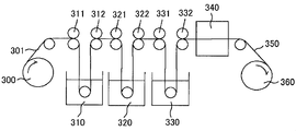
- FIG. 2 is a schematic view showing the concept of a typical production process of a polarizer used in the present invention.
- a polymer film 301 mainly composed of a polyvinyl alcohol-based resin is drawn out from the feed-out unit 300, immersed in an iodine aqueous solution bath 310, and tensioned in the film longitudinal direction by rolls 311 and 312 having different speed ratios. While being subjected to swelling and dyeing processes.
- the film subjected to the crosslinking treatment is immersed in an aqueous solution bath 330 containing potassium iodide by rolls 331 and 332 and subjected to a water washing treatment.
- the water-washed film is dried by the drying means 340 so that the moisture content is adjusted to, for example, 10% to 30%, and is taken up by the take-up unit 360.
- the polarizer 350 can be obtained by stretching the polymer film containing the polyvinyl alcohol resin as a main component to 5 to 7 times the original length through these steps.
- the protective layer is used for preventing the polarizer from contracting and expanding, and preventing deterioration due to ultraviolet rays.
- the material that is the main component of such a film include cellulose resins such as triacetylcellulose (TAC), polyester-based, polyvinyl alcohol-based, polycarbonate-based, polyamide-based, polyimide-based, polyethersulfone-based, Examples thereof include transparent resins such as polysulfone, polystyrene, polynorbornene, polyolefin, acrylic, and acetate.
- thermosetting resins such as acrylic, urethane, acrylic urethane, epoxy, and silicone, or ultraviolet curable resins are also included.
- each protective layer may be the same or different.
- the protective layer is preferably transparent and has no color.
- the thickness direction retardation is preferably ⁇ 90 nm to +90 nm, more preferably ⁇ 80 nm to +80 nm, and most preferably ⁇ 70 nm to +70 nm.
- the thickness of the protective layer any appropriate thickness can be adopted as long as the preferable thickness direction retardation is obtained.
- the thickness of the protective layer is preferably 100 ⁇ m or less, more preferably 80 ⁇ m or less, and particularly preferably 40 ⁇ m or less.
- an arbitrary manifestation treatment layer may be formed on the surfaces of the optional protective layers 2 and 2 'and the optical films 3 and 3'.
- a treatment layer subjected to a hard coat treatment an antistatic treatment, an antireflection treatment (also referred to as an antireflection treatment), a diffusion treatment (also referred to as an antiglare treatment), or the like is used.
- These surface treatment layers are used for the purpose of preventing the screen from being soiled or damaged, or preventing the display image from becoming difficult to see due to the reflection of indoor fluorescent light or sunlight on the screen.
- the surface treatment layer is formed by fixing a treatment agent for forming the treatment layer on the surface of a base film.
- the base film may also serve as the protective layer or the optical film.
- the surface treatment layer may have a multilayer structure in which a hard coat treatment layer is laminated on an antistatic treatment layer, for example.
- a commercially available surface treatment layer can be used as it is. Examples of commercially available films that have been subjected to hard coat treatment and antistatic treatment include “KC8UX-HA” (trade name) manufactured by Konica Minolta Opto Co., Ltd. Examples of the commercially available surface treatment layer that has been subjected to the antireflection treatment include ReaLook series manufactured by NOF Corporation.
- the display panel device of the present invention includes the polarizing plate and a display panel such as a liquid crystal display panel or an organic EL display panel.
- the polarizing plate and the display panel may be directly bonded, or may be disposed via an arbitrary member such as a touch panel or another optical member.
- each analysis method used in the Example is as follows. (1) Measurement of composition ratio: Nuclear magnetic resonance spectrum meter [manufactured by JEOL Ltd., product name “LA400”] (measurement solvent: heavy DMSO, frequency: 400 MHz, observation nucleus: 1 H, measurement temperature: 70 ° C.) was used. (2) Measuring method of thickness: When the thickness was less than 10 ⁇ m, measurement was performed using a spectrophotometer for thin film [manufactured by Otsuka Electronics Co., Ltd., “instant multiphotometry system MCPD-2000”].
- Transmittance measurement method Using a spectrophotometer [manufactured by Murakami Color Research Laboratory Co., Ltd., product name “DOT-3”], it was measured with light having a wavelength of 550 nm at 23 ° C.
- Folding strength (times) measurement method in accordance with JIS P 8115, with a sample size of 100 mm x 15 mm, with a load of 200 g, the longer side from the stretched film is the longitudinal direction of the film (MD direction) Measured using a [BE202MIT fold resistance tester manufactured by Tester Sangyo Co., Ltd.] in two directions, when cutting out into 2 and when cutting out the long side in the film width direction (TD direction).
- Measuring method of absolute value of photoelastic coefficient (C [550]): Using a spectroscopic ellipsometer (product name “M-220” manufactured by JASCO Corporation), the sample (size 2 cm ⁇ 10 cm) is sandwiched at both ends and stress (5 to 15 N) is applied to the phase difference at the center of the sample. The value (23 ° C.) was measured and calculated from the slope of the function of stress and phase difference value.
- Measuring method of reflection spectrum of display panel device The reflection spectral spectrum was measured in a 23 ° C. room using a spectrocolorimeter [Konica Minolta Sensing Co., Ltd., product name “CM-2600d”].
- DMSO dimethyl sulfoxide
- the polymer is dissolved in methyl ethyl ketone (MEK), coated on a polyethylene terephthalate film (thickness 70 ⁇ m) with an applicator, dried in an air circulation drying oven at 130 ° C., and then peeled off from the polyethylene terephthalate film.
- MEK methyl ethyl ketone
- a film having a thickness of 135 ⁇ m was produced.
- This film was uniaxially stretched 2.1 times in a 130 ° C. air circulation drying oven by a stretching machine to produce a stretched film (retardation film) A-1.
- Table 1 shows the properties of the obtained retardation film A-1.
- Example 2 Example 1 except that the thickness of the film before stretching is 150 ⁇ m instead of 135 ⁇ m, the stretching temperature is 133 ° C. instead of 135 ° C., and the stretching ratio is 2.2 times instead of 2.1 times.
- a stretched film (retardation film) A-2 was produced by the method described above. Table 1 shows the properties of the obtained retardation film A-2.
- Example 3 Example 1 except that the thickness of the film before stretching is 130 ⁇ m instead of 135 ⁇ m, the stretching temperature is 130 ° C. instead of 135 ° C., and the stretching ratio is 2.8 times instead of 2.1 times.
- a stretched film (retardation film) A-3 was prepared by the method described above. Table 1 shows the properties of the obtained retardation film A-3.
- Example 4 The film-forming temperature of the film is changed to 90 ° C. instead of 130 ° C., the thickness of the film before stretching is changed to 100 ⁇ m instead of 135 ⁇ m, the stretching temperature is changed to 135 ° C. instead of 135 ° C., and the draw ratio is changed to 2.1 times.
- a stretched film (retardation film) A-4 was produced in the same manner as in Example 1 except that the ratio was 2.5 times. Table 1 shows the properties of the obtained retardation film A-4.
- Example 5 Example 1 except that the thickness of the film before stretching is 142 ⁇ m instead of 135 ⁇ m, the stretching temperature is 139 ° C. instead of 135 ° C., and the stretching ratio is 1.9 times instead of 2.1 times.
- a stretched film (retardation film) A-5 was produced by the method described above. Table 1 shows the properties of the obtained retardation film A-5.
- Example 6 In the same manner as in Example 1 except that 8.81 g of acetaldehyde was added in place of dimethylacetal and the amount of 2-methoxy-1-naphthaldehyde used was 2.89 g, 11.7 g of white acetaldehyde was added. A polymer was obtained. The polymer had a repeating unit represented by the following formula (IV) as measured by 1HNMR, and the ratio (molar ratio) of l: m: n: o was 11: 54: 28: 7. .
- the polymer is dissolved in methyl ethyl ketone (MEK), coated on a polyethylene terephthalate film (thickness 70 ⁇ m) with an applicator, dried in an air circulation drying oven, and then peeled off from the polyethylene terephthalate film to a thickness of 95 ⁇ m.
- MEK methyl ethyl ketone
- a film was prepared. This film was stretched uniaxially by 2.5 times in a 130 ° C. air circulation drying oven with a stretching machine to prepare a stretched film (retardation film) B.
- the properties of the obtained retardation film B are shown in Table 1.
- DMSO dimethyl sulfoxide
- the polymer is dissolved in methyl ethyl ketone (MEK), coated on a polyethylene terephthalate film (thickness 70 ⁇ m) with an applicator, dried in an air circulation drying oven at 130 ° C., and then peeled off from the polyethylene terephthalate film.
- MEK methyl ethyl ketone
- a film having a thickness of 170 ⁇ m was produced.
- This film was uniaxially stretched 2.1 times in a 130 ° C. air circulation drying oven with a stretching machine to prepare a stretched film (retardation film) C.
- the properties of the obtained retardation film C are shown in Table 1.
- Example 8 67.35 parts of cyclohexanedimethanol (hereinafter abbreviated as CHDM), 90.94 parts of 9,9-bis (4-hydroxy-3-methylphenyl) fluorene (hereinafter abbreviated as BCF), 154.61 parts of diphenyl carbonate, and catalyst
- CHDM cyclohexanedimethanol
- BCF 9,9-bis (4-hydroxy-3-methylphenyl) fluorene
- BCF 9,9-bis (4-hydroxy-3-methylphenyl) fluorene
- Example 9 Similar to Example 8 except that the thickness of the film before stretching is 160 ⁇ m instead of 120 ⁇ m, the stretching temperature is 118 ° C. instead of 126 ° C., and the stretching ratio is 2.4 times instead of 2.1 times.
- a stretched film (retardation film) D-2 was produced by the method described above. Table 1 shows the properties of the obtained retardation film D-2.
- Example 10 After drying 5.0 g of a polyvinyl alcohol resin [trade name “NH-18” (polymerization degree: 1800, saponification degree: 99.0%) manufactured by Nippon Synthetic Chemical Co., Ltd.] at 105 ° C. for 2 hours, Dissolved in 95 ml of dimethyl sulfoxide (DMSO). To this, 2.02 g of 2,4,6-trimethylbenzaldehyde (mesitaldehyde) and 0.44 g of p-toluenesulfonic acid monohydrate were added and stirred at 40 ° C. for 2 hours. To this, 13.41 g of 1,1-diethoxyethane (acetal) was added, and the mixture was further stirred at 40 ° C.
- DMSO dimethyl sulfoxide
- the obtained polyvinyl acetal resin (17.7 parts by weight) was dissolved in toluene (100 parts by weight), and a comma was formed on the surface of 75 ⁇ m thick polyethylene terephthalate [trade name “Lumirror S27-E” manufactured by Toray Industries, Inc.]. Coat uniformly with a coater and dry in a multi-chamber air circulating drying oven at 80 ° C for 20 minutes, 120 ° C for 20 minutes, 140 ° C for 30 minutes, gradually rising from a low temperature. The thickness after drying was 160 ⁇ m. This film was stretched uniaxially by 2.1 times in an air circulating drying oven at 141 ° C. with a stretching machine to produce a stretched film (retardation film) E. The properties of the obtained retardation film E are shown in Table 1.
- Example 2 Example 1 except that the thickness of the film before stretching is 140 ⁇ m instead of 135 ⁇ m, the stretching temperature is 145 ° C. instead of 135 ° C., and the stretching ratio is 1.4 times instead of 2.1 times.
- a stretched film (retardation film) G was prepared by the method described above. The properties of the obtained retardation film G are shown in Table 1.
- Example 3 The film thickness before stretching is 100 ⁇ m instead of 135 ⁇ m, the stretching temperature is 130 ° C. instead of 135 ° C., and the stretching direction and magnification are 2.0 times longitudinal uniaxial stretching instead of 2.1 times transverse uniaxial stretching.
- a stretched film (retardation film) H was produced in the same manner as in Example 1 except that. The properties of the obtained retardation film H are shown in Table 1.
- This circularly polarizing plate was bonded to the viewing side of the organic EL panel [trade name “15EL9500” manufactured by LG Display Co., Ltd.] via the same acrylic pressure-sensitive adhesive (20 ⁇ m) to prepare a display panel device.
- the reflection spectral spectrum of the obtained display panel device was measured using a spectrocolorimeter [trade name “CM-2600d” manufactured by Konica Minolta Sensing Co., Ltd.].
- the organic EL panel used for evaluation was used after peeling off the antireflection film bonded to the surface in advance.
- Table 1 and FIG. 3 for Example 1 and Comparative Examples 1 and 2.
- chromaticity (reflection hue) at 45 points on the display screen was measured with a spectrocolorimeter [trade name “CM-2600d” manufactured by Konica Minolta Sensing Co., Ltd.].
- the measurement point was the central portion of a 45-divided area that was created by dividing the display screen uniformly into 5 and 9 sections vertically and horizontally. Further, after the display panel device was stored in a constant temperature oven at 85 ° C. for 96 hours (heating test), the chromaticity at 45 points on the display screen was measured in the same manner. Furthermore, the uniformity of the reflected color of the entire display screen was visually evaluated. The results are shown in Table 1, and for Example 1 and Comparative Example 4 in FIG. The x, y chromaticity diagram shown in FIG. 4 plots chromaticity at 45 points on the display screen as chromaticity coordinates (x, y), and the larger the change in the plot, the more the color in the display screen. The change in the degree is large, which is not preferable as a display device.
- Example 1 the reflection is suppressed in the entire visible light region, the apparent reflection color is black, and the properties excellent as a retardation film used for the antireflection circularly polarizing plate of the display It turns out that it has. Similar results were obtained for the other Examples 2 to 10. On the other hand, in Comparative Examples 1 and 2, the short-wavelength side and the long-wavelength side reflection are large, the apparent reflection colors are blue and red, and the retardation film used for the antireflection circularly polarizing plate of the display is as follows. It turns out that it is not suitable.
- Polarizing plate 300 Feeding part 310 Iodine aqueous solution bath 320 Bath of aqueous solution containing boric acid and potassium iodide 330 Including potassium iodide Aqueous bath 340 Drying means 350 Polarizer 360 Winding unit
Priority Applications (5)
| Application Number | Priority Date | Filing Date | Title |
|---|---|---|---|
| CN201180058702.XA CN103250077B (zh) | 2010-12-06 | 2011-12-06 | 有机el显示器用防反射圆偏振片及有机el显示器 |
| JP2012547864A JPWO2012077663A1 (ja) | 2010-12-06 | 2011-12-06 | 有機elディスプレイ用反射防止円偏光板および有機elディスプレイ |
| KR1020137017738A KR20130103595A (ko) | 2010-12-06 | 2011-12-06 | 유기 el 디스플레이용 반사방지 원편광판 및 유기 el 디스플레이 |
| KR1020177034456A KR20170134790A (ko) | 2010-12-06 | 2011-12-06 | 위상차 필름, 편광판, 및 표시패널장치 |
| US13/991,478 US9442233B2 (en) | 2010-12-06 | 2011-12-06 | Anti-reflection circularly polarizing plate for organic EL display and organic EL display |
Applications Claiming Priority (2)
| Application Number | Priority Date | Filing Date | Title |
|---|---|---|---|
| JP2010-271860 | 2010-12-06 | ||
| JP2010271860 | 2010-12-06 |
Publications (1)
| Publication Number | Publication Date |
|---|---|
| WO2012077663A1 true WO2012077663A1 (ja) | 2012-06-14 |
Family
ID=46207151
Family Applications (1)
| Application Number | Title | Priority Date | Filing Date |
|---|---|---|---|
| PCT/JP2011/078149 WO2012077663A1 (ja) | 2010-12-06 | 2011-12-06 | 位相差フィルム、偏光板、および表示パネル装置 |
Country Status (6)
| Country | Link |
|---|---|
| US (1) | US9442233B2 (ko) |
| JP (4) | JPWO2012077663A1 (ko) |
| KR (3) | KR20150085109A (ko) |
| CN (1) | CN103250077B (ko) |
| TW (1) | TWI448750B (ko) |
| WO (1) | WO2012077663A1 (ko) |
Cited By (17)
| Publication number | Priority date | Publication date | Assignee | Title |
|---|---|---|---|---|
| JP2013174815A (ja) * | 2012-02-27 | 2013-09-05 | Nitto Denko Corp | 位相差フィルム及びその製造方法、偏光板、及び表示装置 |
| WO2014002929A1 (ja) * | 2012-06-29 | 2014-01-03 | 日東電工株式会社 | 偏光板および有機elパネル |
| JP2014010315A (ja) * | 2012-06-29 | 2014-01-20 | Dainippon Printing Co Ltd | タッチパネル用センサーフィルム及びそれを用いた表示装置 |
| WO2014021151A1 (ja) * | 2012-07-31 | 2014-02-06 | 日東電工株式会社 | 位相差フィルムの製造方法 |
| US20140168579A1 (en) * | 2012-12-17 | 2014-06-19 | Cheil Industries Inc. | Polarizing plate and liquid crystal display apparatus including the same |
| US20140168767A1 (en) * | 2012-12-17 | 2014-06-19 | Cheil Industries Inc. | Polarizing plate, method of preparing the same, and liquid crystal display apparatus including the same |
| JP2015111311A (ja) * | 2015-03-20 | 2015-06-18 | 日東電工株式会社 | 位相差フィルム |
| JP2015129970A (ja) * | 2015-03-20 | 2015-07-16 | 日東電工株式会社 | 位相差フィルム |
| WO2016067976A1 (ja) * | 2014-10-27 | 2016-05-06 | 三井化学株式会社 | 高分子圧電フィルム |
| US9400345B2 (en) | 2012-06-29 | 2016-07-26 | Nitto Denko Corporation | Circular polarizing plate and organic electroluminescence panel |
| JP2016138963A (ja) * | 2015-01-27 | 2016-08-04 | 株式会社日本触媒 | 光学フィルム、その利用およびその製造方法 |
| US9796146B2 (en) | 2013-03-29 | 2017-10-24 | Nitto Denko Corporation | Methods for producing phase-difference film and circularly polarizing plate involving simultaneous reduction of clip pitch on one side and increase of clip pitch on another side |
| US9804313B2 (en) | 2013-03-29 | 2017-10-31 | Nitto Denko Corporation | Methods for producing phase-difference film and circularly polarizing plate involving simultaneous reduction of clip pitch on one side and increase of clip pitch on another side |
| US9950461B2 (en) | 2013-06-10 | 2018-04-24 | Nitto Denko Corporation | Production method for phase shift film and circular polarizing plate involving bilaterally symmetric loops with non-simultaneous reduction of clip pitch |
| JP2019091091A (ja) * | 2013-02-07 | 2019-06-13 | 日東電工株式会社 | 円偏光板および屈曲可能な表示装置 |
| WO2020162298A1 (ja) * | 2019-02-08 | 2020-08-13 | 日東電工株式会社 | 画像表示装置およびその製造方法 |
| WO2023171710A1 (ja) * | 2022-03-09 | 2023-09-14 | 株式会社クラレ | ポリビニルアルコールフィルム及びポリビニルアルコールフィルムの製造方法 |
Families Citing this family (19)
| Publication number | Priority date | Publication date | Assignee | Title |
|---|---|---|---|---|
| JP2014170221A (ja) | 2013-02-07 | 2014-09-18 | Nitto Denko Corp | 円偏光板および屈曲可能な表示装置 |
| CN103454712B (zh) * | 2013-09-10 | 2015-11-18 | 中国科学技术大学 | 基于像素的波片阵列及其制备方法 |
| KR20160146702A (ko) | 2014-04-16 | 2016-12-21 | 닛토덴코 가부시키가이샤 | 위상차 필름, 원편광판 및 화상 표시 장치 |
| TWI544228B (zh) * | 2014-04-21 | 2016-08-01 | 王仁宏 | 光學模組及用於光學裝置之光學功能膜 |
| KR101731676B1 (ko) | 2014-07-23 | 2017-05-02 | 삼성에스디아이 주식회사 | 편광판 및 이를 포함하는 광학표시장치 |
| CN105676318B (zh) * | 2014-12-08 | 2018-06-05 | 三星电子株式会社 | 抗反射膜和包括其的有机发光器件 |
| KR101623086B1 (ko) * | 2014-12-08 | 2016-05-20 | 삼성전자 주식회사 | 반사방지필름 및 이를 구비한 유기발광장치 |
| JP5913648B1 (ja) * | 2015-01-23 | 2016-04-27 | 日東電工株式会社 | 位相差層付偏光板および画像表示装置 |
| KR20170102953A (ko) * | 2015-02-13 | 2017-09-12 | 미쯔이가가꾸가부시끼가이샤 | 고분자 압전 필름 및 그의 제조 방법 |
| CN107430238B (zh) * | 2015-03-31 | 2020-03-03 | 富士胶片株式会社 | 圆偏振片以及可弯曲的显示装置 |
| KR20170097921A (ko) * | 2016-02-19 | 2017-08-29 | 삼성에스디아이 주식회사 | 편광자 보호 필름, 이를 포함하는 편광판 및 편광판을 포함하는 표시 장치 |
| KR102010759B1 (ko) | 2016-03-08 | 2019-08-14 | 주식회사 엘지화학 | 디스플레이 장치 |
| JP2018197848A (ja) * | 2017-05-24 | 2018-12-13 | 大阪ガスケミカル株式会社 | 偏光板保護フィルム及びその製造方法、並びに偏光板 |
| EP3654077B1 (en) | 2017-07-10 | 2023-02-22 | LG Chem, Ltd. | Circular polarizing plate |
| KR20180057586A (ko) * | 2018-05-11 | 2018-05-30 | 동우 화인켐 주식회사 | 편광판 및 이를 포함하는 화상 표시 장치 |
| US10890805B2 (en) | 2018-12-12 | 2021-01-12 | Sharp Kabushiki Kaisha | Liquid crystal display device |
| KR102576989B1 (ko) | 2019-07-30 | 2023-09-08 | 삼성에스디아이 주식회사 | 편광판 및 이를 포함하는 광학표시장치 |
| KR20210117391A (ko) * | 2020-03-18 | 2021-09-29 | 삼성디스플레이 주식회사 | 표시 장치 |
| KR20220163810A (ko) | 2021-06-03 | 2022-12-12 | 삼성에스디아이 주식회사 | 편광판 및 이를 포함하는 광학표시장치 |
Citations (3)
| Publication number | Priority date | Publication date | Assignee | Title |
|---|---|---|---|---|
| JP2007161994A (ja) * | 2005-11-21 | 2007-06-28 | Nitto Denko Corp | ナフチル基を有する重合体を含有する光学フィルム |
| JP2008102498A (ja) * | 2006-09-22 | 2008-05-01 | Jsr Corp | 位相差フィルムの製造方法、位相差フィルムおよびその用途 |
| JP2009063983A (ja) * | 2006-12-21 | 2009-03-26 | Fujifilm Corp | 光学フィルム、及びそれを有する偏光板 |
Family Cites Families (22)
| Publication number | Priority date | Publication date | Assignee | Title |
|---|---|---|---|---|
| JP2002071949A (ja) | 2000-09-01 | 2002-03-12 | Fuji Photo Film Co Ltd | 光学補償シート、偏光板およびそれを用いた液晶表示装置 |
| JP4074762B2 (ja) | 2002-01-21 | 2008-04-09 | 富士フイルム株式会社 | 光学補償フィルムおよびその製造方法、円偏光板、画像表示装置 |
| JP2004134306A (ja) * | 2002-10-11 | 2004-04-30 | Fuji Photo Film Co Ltd | エレクトロルミネッセンスディスプレイ |
| JP4218305B2 (ja) | 2002-10-21 | 2009-02-04 | コニカミノルタホールディングス株式会社 | ポリマーフィルムの製造方法及び位相差フィルム |
| EP1662589A3 (en) * | 2004-11-30 | 2010-09-15 | LG Display Co., Ltd. | Organic electroluminescent device having a polarizer |
| JP2006171235A (ja) | 2004-12-14 | 2006-06-29 | Nitto Denko Corp | 円偏光板、及び光学フィルム、及び画像表示装置 |
| JP4618675B2 (ja) * | 2005-02-08 | 2011-01-26 | 日東電工株式会社 | 位相差フィルム、偏光素子、液晶パネルおよび液晶表示装置 |
| WO2007034908A1 (ja) * | 2005-09-26 | 2007-03-29 | Nitto Denko Corporation | 光学補償層付偏光板、光学補償層付偏光板を用いた液晶パネル、液晶表示装置、および画像表示装置 |
| CN100587526C (zh) | 2005-11-21 | 2010-02-03 | 日东电工株式会社 | 含有具有萘基的聚合物的光学薄膜 |
| KR100904124B1 (ko) | 2006-05-29 | 2009-06-24 | 닛토덴코 가부시키가이샤 | 액정 패널 및 액정 표시 장치 |
| JP2008009389A (ja) | 2006-05-29 | 2008-01-17 | Nitto Denko Corp | 液晶パネルおよび液晶表示装置 |
| JP5252611B2 (ja) * | 2006-09-15 | 2013-07-31 | 日東電工株式会社 | 位相差フィルム、光学積層体、液晶パネル、及び液晶表示装置 |
| KR20080027203A (ko) | 2006-09-22 | 2008-03-26 | 제이에스알 가부시끼가이샤 | 위상차 필름의 제조 방법, 위상차 필름 및 그의 용도 |
| WO2008034716A1 (en) | 2006-09-22 | 2008-03-27 | Clariant International Ltd | Use of ethoxylated alkylamines for modification of the surface tension of plastics |
| JP2009048157A (ja) | 2006-12-21 | 2009-03-05 | Fujifilm Corp | 液晶表示装置 |
| JP5252615B2 (ja) * | 2007-01-09 | 2013-07-31 | 日東電工株式会社 | 液晶パネル、及び液晶表示装置 |
| JP5279336B2 (ja) * | 2007-07-12 | 2013-09-04 | 日東電工株式会社 | 液晶パネルおよび液晶表示装置 |
| JP4726148B2 (ja) * | 2007-11-20 | 2011-07-20 | 日東電工株式会社 | 液晶パネル、及び液晶表示装置 |
| JP5375043B2 (ja) | 2007-11-30 | 2013-12-25 | Jsr株式会社 | 積層光学フィルムの製造方法、積層光学フィルムおよびその用途 |
| JP2009251288A (ja) * | 2008-04-07 | 2009-10-29 | Nitto Denko Corp | 楕円偏光板並びにその製造方法 |
| KR101651306B1 (ko) | 2008-12-05 | 2016-08-25 | 테이진 카세이 가부시키가이샤 | 광학 필름 |
| WO2010071079A1 (ja) * | 2008-12-16 | 2010-06-24 | 帝人化成株式会社 | 光学フィルム |
-
2011
- 2011-12-06 KR KR1020157017563A patent/KR20150085109A/ko not_active Application Discontinuation
- 2011-12-06 KR KR1020177034456A patent/KR20170134790A/ko not_active Application Discontinuation
- 2011-12-06 KR KR1020137017738A patent/KR20130103595A/ko active Application Filing
- 2011-12-06 TW TW100144860A patent/TWI448750B/zh active
- 2011-12-06 JP JP2012547864A patent/JPWO2012077663A1/ja active Pending
- 2011-12-06 US US13/991,478 patent/US9442233B2/en active Active
- 2011-12-06 CN CN201180058702.XA patent/CN103250077B/zh active Active
- 2011-12-06 WO PCT/JP2011/078149 patent/WO2012077663A1/ja active Application Filing
-
2014
- 2014-06-23 JP JP2014128513A patent/JP2014186351A/ja active Pending
-
2016
- 2016-05-09 JP JP2016094037A patent/JP2016173591A/ja active Pending
-
2017
- 2017-11-14 JP JP2017219154A patent/JP2018032044A/ja active Pending
Patent Citations (3)
| Publication number | Priority date | Publication date | Assignee | Title |
|---|---|---|---|---|
| JP2007161994A (ja) * | 2005-11-21 | 2007-06-28 | Nitto Denko Corp | ナフチル基を有する重合体を含有する光学フィルム |
| JP2008102498A (ja) * | 2006-09-22 | 2008-05-01 | Jsr Corp | 位相差フィルムの製造方法、位相差フィルムおよびその用途 |
| JP2009063983A (ja) * | 2006-12-21 | 2009-03-26 | Fujifilm Corp | 光学フィルム、及びそれを有する偏光板 |
Cited By (35)
| Publication number | Priority date | Publication date | Assignee | Title |
|---|---|---|---|---|
| JP2013174815A (ja) * | 2012-02-27 | 2013-09-05 | Nitto Denko Corp | 位相差フィルム及びその製造方法、偏光板、及び表示装置 |
| WO2013128954A1 (ja) * | 2012-02-27 | 2013-09-06 | 日東電工株式会社 | 位相差フィルム及びその製造方法、偏光板、及び表示装置 |
| US9389352B2 (en) | 2012-02-27 | 2016-07-12 | Nitto Denko Corportation | Retardation film and production method therefor, polarizing plate, and display device |
| TWI596386B (zh) * | 2012-06-29 | 2017-08-21 | Nitto Denko Corp | Polarizer and organic EL panel |
| US9459389B2 (en) | 2012-06-29 | 2016-10-04 | Nitto Denko Corporation | Polarizing plate and organic EL panel |
| WO2014002929A1 (ja) * | 2012-06-29 | 2014-01-03 | 日東電工株式会社 | 偏光板および有機elパネル |
| JP2014010315A (ja) * | 2012-06-29 | 2014-01-20 | Dainippon Printing Co Ltd | タッチパネル用センサーフィルム及びそれを用いた表示装置 |
| TWI607250B (zh) * | 2012-06-29 | 2017-12-01 | Nitto Denko Corp | Circular polarizer and organic EL panel |
| US9400345B2 (en) | 2012-06-29 | 2016-07-26 | Nitto Denko Corporation | Circular polarizing plate and organic electroluminescence panel |
| EP2869098A4 (en) * | 2012-06-29 | 2016-02-17 | Nitto Denko Corp | POLARIZING PLATE AND ORGANIC EL PANEL |
| JP2014010300A (ja) * | 2012-06-29 | 2014-01-20 | Nitto Denko Corp | 偏光板および有機elパネル |
| EP2869098A1 (en) | 2012-06-29 | 2015-05-06 | Nitto Denko Corporation | Polarizing plate and organic el panel |
| CN104428700B (zh) * | 2012-06-29 | 2017-03-01 | 日东电工株式会社 | 偏振板及有机el面板 |
| CN104094142A (zh) * | 2012-07-31 | 2014-10-08 | 日东电工株式会社 | 相位差膜的制造方法 |
| KR20140105792A (ko) * | 2012-07-31 | 2014-09-02 | 닛토덴코 가부시키가이샤 | 위상차 필름의 제조 방법 |
| KR101633203B1 (ko) * | 2012-07-31 | 2016-06-23 | 닛토덴코 가부시키가이샤 | 위상차 필름의 제조 방법 |
| JP2014029388A (ja) * | 2012-07-31 | 2014-02-13 | Nitto Denko Corp | 位相差フィルムの製造方法 |
| WO2014021151A1 (ja) * | 2012-07-31 | 2014-02-06 | 日東電工株式会社 | 位相差フィルムの製造方法 |
| US20140168579A1 (en) * | 2012-12-17 | 2014-06-19 | Cheil Industries Inc. | Polarizing plate and liquid crystal display apparatus including the same |
| US9358768B2 (en) * | 2012-12-17 | 2016-06-07 | Samsung Sdi Co., Ltd. | Polarizing plate, method of preparing the same, and liquid crystal display apparatus including the same |
| US9291850B2 (en) * | 2012-12-17 | 2016-03-22 | Cheil Industries Inc. | Polarizing plate and liquid crystal display apparatus including the same |
| US20140168767A1 (en) * | 2012-12-17 | 2014-06-19 | Cheil Industries Inc. | Polarizing plate, method of preparing the same, and liquid crystal display apparatus including the same |
| JP2019091091A (ja) * | 2013-02-07 | 2019-06-13 | 日東電工株式会社 | 円偏光板および屈曲可能な表示装置 |
| JP2020197751A (ja) * | 2013-02-07 | 2020-12-10 | 日東電工株式会社 | 円偏光板 |
| JP7252924B2 (ja) | 2013-02-07 | 2023-04-05 | 日東電工株式会社 | 有機el表示装置 |
| US9796146B2 (en) | 2013-03-29 | 2017-10-24 | Nitto Denko Corporation | Methods for producing phase-difference film and circularly polarizing plate involving simultaneous reduction of clip pitch on one side and increase of clip pitch on another side |
| US9804313B2 (en) | 2013-03-29 | 2017-10-31 | Nitto Denko Corporation | Methods for producing phase-difference film and circularly polarizing plate involving simultaneous reduction of clip pitch on one side and increase of clip pitch on another side |
| US9950461B2 (en) | 2013-06-10 | 2018-04-24 | Nitto Denko Corporation | Production method for phase shift film and circular polarizing plate involving bilaterally symmetric loops with non-simultaneous reduction of clip pitch |
| WO2016067976A1 (ja) * | 2014-10-27 | 2016-05-06 | 三井化学株式会社 | 高分子圧電フィルム |
| JPWO2016067976A1 (ja) * | 2014-10-27 | 2017-04-27 | 三井化学株式会社 | 高分子圧電フィルム |
| JP2016138963A (ja) * | 2015-01-27 | 2016-08-04 | 株式会社日本触媒 | 光学フィルム、その利用およびその製造方法 |
| JP2015129970A (ja) * | 2015-03-20 | 2015-07-16 | 日東電工株式会社 | 位相差フィルム |
| JP2015111311A (ja) * | 2015-03-20 | 2015-06-18 | 日東電工株式会社 | 位相差フィルム |
| WO2020162298A1 (ja) * | 2019-02-08 | 2020-08-13 | 日東電工株式会社 | 画像表示装置およびその製造方法 |
| WO2023171710A1 (ja) * | 2022-03-09 | 2023-09-14 | 株式会社クラレ | ポリビニルアルコールフィルム及びポリビニルアルコールフィルムの製造方法 |
Also Published As
| Publication number | Publication date |
|---|---|
| JP2016173591A (ja) | 2016-09-29 |
| CN103250077B (zh) | 2015-12-09 |
| KR20130103595A (ko) | 2013-09-23 |
| CN103250077A (zh) | 2013-08-14 |
| US20130249378A1 (en) | 2013-09-26 |
| JPWO2012077663A1 (ja) | 2014-05-19 |
| KR20170134790A (ko) | 2017-12-06 |
| TW201243403A (en) | 2012-11-01 |
| JP2018032044A (ja) | 2018-03-01 |
| JP2014186351A (ja) | 2014-10-02 |
| KR20150085109A (ko) | 2015-07-22 |
| US9442233B2 (en) | 2016-09-13 |
| TWI448750B (zh) | 2014-08-11 |
Similar Documents
| Publication | Publication Date | Title |
|---|---|---|
| JP2018032044A (ja) | 位相差フィルム、偏光板、および表示パネル装置 | |
| JP3984277B2 (ja) | ナフチル基を有する重合体を含有する光学フィルム | |
| JP4618675B2 (ja) | 位相差フィルム、偏光素子、液晶パネルおよび液晶表示装置 | |
| US7807239B2 (en) | Optical film containing polymer having naphtyl group | |
| US8911837B2 (en) | Retardation film, optical laminated body, liquid crystal panel, and liquid crystal display | |
| JP5995160B2 (ja) | 位相差フィルム及びその製造方法、偏光板、及び表示装置 | |
| CN105487141A (zh) | 偏振板及有机el面板 | |
| JP2007121352A (ja) | 位相差フィルム、及びその製造方法、並びに光学補償偏光板 | |
| JP2007121351A (ja) | 位相差フィルム、及びその製造方法、並びに光学補償偏光板 | |
| JP4693094B2 (ja) | 位相差フィルムの製造方法 | |
| JP4721858B2 (ja) | 位相差フィルムの製造方法 | |
| JP2007093654A (ja) | 位相差フィルム、及びその製造方法、並びに光学補償偏光板 |
Legal Events
| Date | Code | Title | Description |
|---|---|---|---|
| 121 | Ep: the epo has been informed by wipo that ep was designated in this application |
Ref document number: 11847427 Country of ref document: EP Kind code of ref document: A1 |
|
| WWE | Wipo information: entry into national phase |
Ref document number: 13991478 Country of ref document: US |
|
| ENP | Entry into the national phase |
Ref document number: 2012547864 Country of ref document: JP Kind code of ref document: A |
|
| NENP | Non-entry into the national phase |
Ref country code: DE |
|
| ENP | Entry into the national phase |
Ref document number: 20137017738 Country of ref document: KR Kind code of ref document: A |
|
| 122 | Ep: pct application non-entry in european phase |
Ref document number: 11847427 Country of ref document: EP Kind code of ref document: A1 |