WO2013128954A1 - 位相差フィルム及びその製造方法、偏光板、及び表示装置 - Google Patents
位相差フィルム及びその製造方法、偏光板、及び表示装置 Download PDFInfo
- Publication number
- WO2013128954A1 WO2013128954A1 PCT/JP2013/050279 JP2013050279W WO2013128954A1 WO 2013128954 A1 WO2013128954 A1 WO 2013128954A1 JP 2013050279 W JP2013050279 W JP 2013050279W WO 2013128954 A1 WO2013128954 A1 WO 2013128954A1
- Authority
- WO
- WIPO (PCT)
- Prior art keywords
- retardation film
- film
- retardation
- polymer
- contraction
- Prior art date
Links
Images


Classifications
-
- B—PERFORMING OPERATIONS; TRANSPORTING
- B29—WORKING OF PLASTICS; WORKING OF SUBSTANCES IN A PLASTIC STATE IN GENERAL
- B29C—SHAPING OR JOINING OF PLASTICS; SHAPING OF MATERIAL IN A PLASTIC STATE, NOT OTHERWISE PROVIDED FOR; AFTER-TREATMENT OF THE SHAPED PRODUCTS, e.g. REPAIRING
- B29C55/00—Shaping by stretching, e.g. drawing through a die; Apparatus therefor
- B29C55/02—Shaping by stretching, e.g. drawing through a die; Apparatus therefor of plates or sheets
- B29C55/04—Shaping by stretching, e.g. drawing through a die; Apparatus therefor of plates or sheets uniaxial, e.g. oblique
- B29C55/08—Shaping by stretching, e.g. drawing through a die; Apparatus therefor of plates or sheets uniaxial, e.g. oblique transverse to the direction of feed
- B29C55/085—Shaping by stretching, e.g. drawing through a die; Apparatus therefor of plates or sheets uniaxial, e.g. oblique transverse to the direction of feed in several stretching steps
-
- C—CHEMISTRY; METALLURGY
- C08—ORGANIC MACROMOLECULAR COMPOUNDS; THEIR PREPARATION OR CHEMICAL WORKING-UP; COMPOSITIONS BASED THEREON
- C08J—WORKING-UP; GENERAL PROCESSES OF COMPOUNDING; AFTER-TREATMENT NOT COVERED BY SUBCLASSES C08B, C08C, C08F, C08G or C08H
- C08J5/00—Manufacture of articles or shaped materials containing macromolecular substances
- C08J5/18—Manufacture of films or sheets
-
- G—PHYSICS
- G02—OPTICS
- G02B—OPTICAL ELEMENTS, SYSTEMS OR APPARATUS
- G02B1/00—Optical elements characterised by the material of which they are made; Optical coatings for optical elements
- G02B1/04—Optical elements characterised by the material of which they are made; Optical coatings for optical elements made of organic materials, e.g. plastics
-
- G—PHYSICS
- G02—OPTICS
- G02B—OPTICAL ELEMENTS, SYSTEMS OR APPARATUS
- G02B27/00—Optical systems or apparatus not provided for by any of the groups G02B1/00 - G02B26/00, G02B30/00
- G02B27/28—Optical systems or apparatus not provided for by any of the groups G02B1/00 - G02B26/00, G02B30/00 for polarising
- G02B27/286—Optical systems or apparatus not provided for by any of the groups G02B1/00 - G02B26/00, G02B30/00 for polarising for controlling or changing the state of polarisation, e.g. transforming one polarisation state into another
-
- G—PHYSICS
- G02—OPTICS
- G02B—OPTICAL ELEMENTS, SYSTEMS OR APPARATUS
- G02B5/00—Optical elements other than lenses
- G02B5/30—Polarising elements
- G02B5/3025—Polarisers, i.e. arrangements capable of producing a definite output polarisation state from an unpolarised input state
- G02B5/3033—Polarisers, i.e. arrangements capable of producing a definite output polarisation state from an unpolarised input state in the form of a thin sheet or foil, e.g. Polaroid
-
- G—PHYSICS
- G02—OPTICS
- G02B—OPTICAL ELEMENTS, SYSTEMS OR APPARATUS
- G02B5/00—Optical elements other than lenses
- G02B5/30—Polarising elements
- G02B5/3083—Birefringent or phase retarding elements
-
- G—PHYSICS
- G02—OPTICS
- G02F—OPTICAL DEVICES OR ARRANGEMENTS FOR THE CONTROL OF LIGHT BY MODIFICATION OF THE OPTICAL PROPERTIES OF THE MEDIA OF THE ELEMENTS INVOLVED THEREIN; NON-LINEAR OPTICS; FREQUENCY-CHANGING OF LIGHT; OPTICAL LOGIC ELEMENTS; OPTICAL ANALOGUE/DIGITAL CONVERTERS
- G02F1/00—Devices or arrangements for the control of the intensity, colour, phase, polarisation or direction of light arriving from an independent light source, e.g. switching, gating or modulating; Non-linear optics
- G02F1/01—Devices or arrangements for the control of the intensity, colour, phase, polarisation or direction of light arriving from an independent light source, e.g. switching, gating or modulating; Non-linear optics for the control of the intensity, phase, polarisation or colour
- G02F1/13—Devices or arrangements for the control of the intensity, colour, phase, polarisation or direction of light arriving from an independent light source, e.g. switching, gating or modulating; Non-linear optics for the control of the intensity, phase, polarisation or colour based on liquid crystals, e.g. single liquid crystal display cells
- G02F1/133—Constructional arrangements; Operation of liquid crystal cells; Circuit arrangements
- G02F1/1333—Constructional arrangements; Manufacturing methods
- G02F1/1335—Structural association of cells with optical devices, e.g. polarisers or reflectors
- G02F1/13363—Birefringent elements, e.g. for optical compensation
-
- B—PERFORMING OPERATIONS; TRANSPORTING
- B29—WORKING OF PLASTICS; WORKING OF SUBSTANCES IN A PLASTIC STATE IN GENERAL
- B29D—PRODUCING PARTICULAR ARTICLES FROM PLASTICS OR FROM SUBSTANCES IN A PLASTIC STATE
- B29D11/00—Producing optical elements, e.g. lenses or prisms
- B29D11/00634—Production of filters
- B29D11/00644—Production of filters polarizing
-
- B—PERFORMING OPERATIONS; TRANSPORTING
- B29—WORKING OF PLASTICS; WORKING OF SUBSTANCES IN A PLASTIC STATE IN GENERAL
- B29D—PRODUCING PARTICULAR ARTICLES FROM PLASTICS OR FROM SUBSTANCES IN A PLASTIC STATE
- B29D11/00—Producing optical elements, e.g. lenses or prisms
- B29D11/00951—Measuring, controlling or regulating
-
- B—PERFORMING OPERATIONS; TRANSPORTING
- B29—WORKING OF PLASTICS; WORKING OF SUBSTANCES IN A PLASTIC STATE IN GENERAL
- B29K—INDEXING SCHEME ASSOCIATED WITH SUBCLASSES B29B, B29C OR B29D, RELATING TO MOULDING MATERIALS OR TO MATERIALS FOR MOULDS, REINFORCEMENTS, FILLERS OR PREFORMED PARTS, e.g. INSERTS
- B29K2101/00—Use of unspecified macromolecular compounds as moulding material
-
- B—PERFORMING OPERATIONS; TRANSPORTING
- B29—WORKING OF PLASTICS; WORKING OF SUBSTANCES IN A PLASTIC STATE IN GENERAL
- B29K—INDEXING SCHEME ASSOCIATED WITH SUBCLASSES B29B, B29C OR B29D, RELATING TO MOULDING MATERIALS OR TO MATERIALS FOR MOULDS, REINFORCEMENTS, FILLERS OR PREFORMED PARTS, e.g. INSERTS
- B29K2995/00—Properties of moulding materials, reinforcements, fillers, preformed parts or moulds
- B29K2995/0018—Properties of moulding materials, reinforcements, fillers, preformed parts or moulds having particular optical properties, e.g. fluorescent or phosphorescent
- B29K2995/0031—Refractive
- B29K2995/0032—Birefringent
-
- B—PERFORMING OPERATIONS; TRANSPORTING
- B29—WORKING OF PLASTICS; WORKING OF SUBSTANCES IN A PLASTIC STATE IN GENERAL
- B29L—INDEXING SCHEME ASSOCIATED WITH SUBCLASS B29C, RELATING TO PARTICULAR ARTICLES
- B29L2011/00—Optical elements, e.g. lenses, prisms
- B29L2011/0066—Optical filters
-
- C—CHEMISTRY; METALLURGY
- C08—ORGANIC MACROMOLECULAR COMPOUNDS; THEIR PREPARATION OR CHEMICAL WORKING-UP; COMPOSITIONS BASED THEREON
- C08J—WORKING-UP; GENERAL PROCESSES OF COMPOUNDING; AFTER-TREATMENT NOT COVERED BY SUBCLASSES C08B, C08C, C08F, C08G or C08H
- C08J2329/00—Characterised by the use of homopolymers or copolymers of compounds having one or more unsaturated aliphatic radicals, each having only one carbon-to-carbon double bond, and at least one being terminated by an alcohol, ether, aldehydo, ketonic, acetal, or ketal radical; Hydrolysed polymers of esters of unsaturated alcohols with saturated carboxylic acids; Derivatives of such polymer
- C08J2329/02—Homopolymers or copolymers of unsaturated alcohols
- C08J2329/04—Polyvinyl alcohol; Partially hydrolysed homopolymers or copolymers of esters of unsaturated alcohols with saturated carboxylic acids
-
- C—CHEMISTRY; METALLURGY
- C08—ORGANIC MACROMOLECULAR COMPOUNDS; THEIR PREPARATION OR CHEMICAL WORKING-UP; COMPOSITIONS BASED THEREON
- C08J—WORKING-UP; GENERAL PROCESSES OF COMPOUNDING; AFTER-TREATMENT NOT COVERED BY SUBCLASSES C08B, C08C, C08F, C08G or C08H
- C08J2345/00—Characterised by the use of homopolymers or copolymers of compounds having no unsaturated aliphatic radicals in side chain, and having one or more carbon-to-carbon double bonds in a carbocyclic or in a heterocyclic ring system; Derivatives of such polymers
-
- C—CHEMISTRY; METALLURGY
- C08—ORGANIC MACROMOLECULAR COMPOUNDS; THEIR PREPARATION OR CHEMICAL WORKING-UP; COMPOSITIONS BASED THEREON
- C08J—WORKING-UP; GENERAL PROCESSES OF COMPOUNDING; AFTER-TREATMENT NOT COVERED BY SUBCLASSES C08B, C08C, C08F, C08G or C08H
- C08J2369/00—Characterised by the use of polycarbonates; Derivatives of polycarbonates
Definitions
- the present invention relates to a retardation film and a method for producing the same, and a polarizing plate and a display device including the retardation film.
- the present invention is a retardation film having reverse wavelength dispersion characteristics, which is highly reliable in that there is little change in wavelength dispersion, and has little display unevenness due to the location dependence of the change in retardation, And a method for producing the same by stretching a polymer film.
- the retardation film has a wavelength dependency of the retardation value, and a film having a larger retardation value (also called reverse wavelength dispersion characteristic) has been developed.
- Japanese Patent Application No. 2010-271860 describes a retardation film, particularly a retardation film having reverse wavelength dispersion characteristics, for the purpose of producing a large amount of a wide and thin film. From the viewpoint of reliability and the like, a technique for improving the brittleness of the film is disclosed.
- Japanese Patent Application Laid-Open No. 2009-086651 discloses a retardation film having a low melt viscosity, a low environmental load, excellent fluidity, moldability, heat resistance, long-term retardation stability, and wavelength dispersion.
- a technique for providing a circularly polarizing plate and a display device that can be used to achieve a good display with high contrast even when viewed obliquely and without being bluish is disclosed.
- the retardation film when the retardation film is bonded to glass through an adhesive, the retardation film increases at the center of the retardation film for a long period of time under high temperature conditions. It has been found for the first time that the phase difference is reduced at the end of the display, and that such a location dependency in the phase difference change causes display unevenness. And this invention makes the chromatic dispersion change of the retardation film before and after the high temperature treatment within a predetermined range, and adopts a predetermined multi-stage shrinking step in the manufacturing method of the retardation film, This is based on the knowledge that the problem of display unevenness can be solved.
- the retardation film is represented by the following formulas (1) and (2): 0.70 ⁇ Re 1 [450] / Re 1 [550] ⁇ 0.97 (1) 1.5 ⁇ 10 ⁇ 3 ⁇ n ⁇ 6.0 ⁇ 10 ⁇ 3 (2) (Where Re 1 [450] and Re 1 [550] are in-plane retardation values of the retardation film measured with light at a wavelength of 450 nm and 550 nm, respectively, at 23 ° C., and ⁇ n is light having a wavelength of 550 nm. This is the in-plane birefringence of the retardation film measured in step 1).
- the manufacturing method satisfies the following steps: A process of continuously conveying and supplying a long polymer film; A stretching step of stretching the polymer film in a direction transverse to the transport direction; A first shrinking step for shrinking the polymer film in the transverse direction after the stretching step; and After the first shrinking step, it has a second shrinking step of shrinking the polymer film in the lateral direction,
- the contraction temperature T 1 (° C.) in the first contraction step and the contraction temperature T 2 (° C.) in the second contraction step are expressed by the following formula (3): 1 ⁇ (T 1 ⁇ T 2 ) ⁇ 10 (3) It is characterized by satisfying.
- the production method comprises the following steps: After the second shrinking step, further comprising a third shrinking step of shrinking the polymer film in the lateral direction;
- the contraction temperature T 2 (° C.) in the second contraction step and the contraction temperature T 3 (° C.) in the third contraction step are expressed by the following formula (4): 1 ⁇ (T 2 ⁇ T 3 ) ⁇ 10 (4) It is characterized by satisfying.
- the stretching temperature T 0 (° C.) in the stretching step and the shrinking temperature T 1 (° C.) in the first shrinking step are expressed by the following formula (5): 0 ⁇ (T 0 ⁇ T 1 ) ⁇ 10 (5) It is characterized by satisfying.
- the shrinkage temperature T 1 (° C.) in the first shrinkage step the shrinkage temperature T 2 (° C.) in the second shrinkage step, and the shrinkage temperature T 3 (° C.) in the third shrinkage step.
- a retardation film obtained by the production method is represented by the following formula (7): 2 ° ⁇ (maximum orientation angle ⁇ minimum orientation angle) ⁇ 10 ° (7) It is characterized by satisfying.
- a retardation film obtained by the production method has the following formula (8):
- Re 1 [450] and Re 1 [550] are the in-plane retardation values of the retardation film measured with light having a wavelength of 450 nm and 550 nm at 23 ° C., respectively
- Re 2 [450] and Re 2 [550] is the in-plane retardation value of the retardation film after heat treatment at 90 ° C. for 100 hours measured with light having a wavelength of 450 nm and 550 nm at 23 ° C., respectively. It is characterized by satisfying.
- the retardation film of the present invention has the following formulas (1), (2) and (8): 0.70 ⁇ Re 1 [450] / Re 1 [550] ⁇ 0.97 (1) 1.5 ⁇ 10 ⁇ 3 ⁇ n ⁇ 6.0 ⁇ 10 ⁇ 3 (2)
- Re 2 [450] and Re 2 [550] were measured with light having a wavelength of 450 nm and 550 nm at 23 ° C., respectively, and heat-treated at a temperature of 90 ° C. for 100 hours.
- the retardation value is in-plane retardation value of the retardation film after the treatment).
- the retardation film has the following formula (7): 2 ° ⁇ (maximum orientation angle ⁇ minimum orientation angle) ⁇ 10 ° (7) It is characterized by satisfying.
- the retardation film has a main chain having stretch orientation and a side chain composed of units having an absorption edge at 260 to 380 nm, and the direction in which the main chain extends is It includes a polymer mainly composed of a polymer having crossed side chain surfaces.
- the present invention is also characterized by a polarizing plate comprising the retardation film and a polarizer, and a display device comprising such a polarizing plate.
- the polarizing plate may be a linear polarizing plate or a circular polarizing plate.
- the display device may be an OLED display device.
- the retardation film of the present invention is generally obtained by stretching a polymer film.
- the retardation film refers to one having birefringence in the plane and / or in the thickness direction.
- Re 1 [550] refers to an in-plane retardation value measured at 23 ° C. with light having a wavelength of 550 nm for a retardation film before being subjected to a heat treatment described later.
- the slow axis means the direction in which the in-plane refractive index is maximum.
- Re 1 [450] is the same as Re 1 [550] except that measurement was performed with light having a wavelength of 450 nm.
- the retardation film of the present invention satisfies the relationship of 0.70 ⁇ Re 1 [450] / Re 1 [550] ⁇ 0.97.
- the ratio of Re 1 [550] to Re 1 [450] (Re 1 [450] / Re 1 [550]) of the retardation film of the present invention is preferably 0.75 to 0.95.
- the retardation film having such a wavelength dispersion characteristic when the ratio is within this range, the longer the wavelength, the larger the retardation, and the ideal retardation characteristic can be obtained at each wavelength in the visible region.
- a retardation film having such a wavelength dependency when used in an organic EL display, a retardation film having such a wavelength dependency is produced as a ⁇ / 4 plate, and a circularly polarizing plate or the like can be produced by bonding with a polarizing plate. It is possible to realize a neutral polarizing plate and a display device with less hue wavelength dependency.
- the ratio when the ratio is out of this range, the wavelength dependency of the hue becomes large, and coloring problems occur in the polarizing plate and the display device.
- Re 2 [550] and Re 2 [450] are Re 1 [550] and Re 2 respectively, except that they are measured for a retardation film after heat treatment at a temperature of 90 ° C. for 100 hours. 1 Same as [450].
- the retardation film of the present invention satisfies the relationship of
- the retardation film of the present invention is
- the reflected hue is colored and uneven.
- the retardation film is preferably at 23 ° C., in-plane retardation value measured with light having a wavelength of 550nm (Re 1 [550]) is an in-plane retardation value determined by using light of a wavelength of 650 nm (Re 1 [650]).
- a retardation film having such a wavelength dispersion characteristic has a constant retardation value in a red region. For example, when used in a liquid crystal display device, a phenomenon in which light leaks depending on a viewing angle or a display image is red. It is possible to improve a taste-taking phenomenon (also referred to as a red-ish phenomenon).
- the ratio of Re 1 [550] to Re 1 [650] (Re 1 [650] / Re 1 [550]) of the retardation film is preferably larger than 1, more preferably 1.01 to 1.20. And particularly preferably from 1.02 to 1.15.
- Re 1 [650] / Re 1 [550] in the above range, for example, when the retardation film is used in an organic EL display, even more excellent display characteristics can be obtained.
- the in-plane retardation value of these retardation films can be measured using a product name “AxoScan” manufactured by Axometrics.
- ⁇ n is in-plane birefringence (nx-ny) measured with light having a wavelength of 550 nm.
- the retardation film of the present invention satisfies the relationship of 1.5 ⁇ 10 ⁇ 3 ⁇ n ⁇ 6.0 ⁇ 10 ⁇ 3 .
- the in-plane birefringence ⁇ n is preferably 1.5 ⁇ 10 ⁇ 3 to 5.0 ⁇ 10 ⁇ 3 , more preferably 2.0 ⁇ 10 ⁇ 3 to 4.5 ⁇ 10 ⁇ 3 .
- the stretching step in the production of the retardation film includes a fixed-end stretching, for example, a lateral stretching step or an oblique stretching step, and ⁇ n is set to the above range by adjusting the stretching ratio, stretching temperature, stretching speed, and the like.
- ⁇ n is set to the above range by adjusting the stretching ratio, stretching temperature, stretching speed, and the like.
- ⁇ n when ⁇ n is within this range, it is easy to adjust to an appropriate phase difference, and by designing the phase difference according to the display device, it is possible to provide a display device having excellent front characteristics and viewing angle characteristics. it can. Moreover, when ⁇ n is within this range, it is easy to design the retardation film to be very thin, and it is easy to incorporate it into a thin display device. On the other hand, when ⁇ n is smaller than this range, it is necessary to excessively increase the thickness of the film.
- the retardation film of the present invention is preferably in the range of 2 ° ⁇ (maximum orientation angle ⁇ minimum orientation angle) ⁇ 10 °.
- the maximum value of the orientation angle-the minimum value of the orientation angle is 10 ° or more, coloring occurs, for example, a blueish phenomenon or a redish phenomenon occurs. If it is 2 ° or less, sufficient shrinkage cannot be performed, resulting in poor durability.
- the retardation film of the present invention has a predetermined thickness direction retardation value Rth.
- the slow axis means the direction in which the in-plane refractive index is maximum.
- the Re can be 10 nm or more, and is preferably 50 nm to 500 nm.
- the Re is preferably 200 nm to 400 nm, and more preferably 250 nm to 290 nm.
- the Re is preferably 100 nm to 200 nm, and more preferably 130 nm to 150 nm.
- the retardation film of the present invention may have a ratio NZ (also referred to as NZ coefficient) of nx-nz which is a predetermined thickness direction birefringence and nx-ny which is an in-plane birefringence.
- NZ also referred to as NZ coefficient
- the folding strength in the longitudinal direction of the film, which is the stretching direction becomes strong, but the folding strength in the width direction becomes very weak.
- a state in which a force for regulating the width is generated in an angular direction intersecting the stretching direction (for example, in the case of lateral uniaxial stretching, in a direction perpendicular to the width direction of the film which is the stretching direction).
- the molecules can be oriented not only in the stretching direction but also in the angular direction intersecting with the stretching direction.
- the refractive index relationship can be nx> ny> nz.
- the folding strength in the stretching direction and the folding strength in the width direction can be compatible at a high level.
- the transmittance of the retardation film of the present invention is preferably 80% or more, more preferably 85% or more, and particularly preferably 89% or more.
- the retardation film of the present invention is produced by orienting a polymer film by stretching. Specifically, in the method for producing a retardation film of the present invention, first, a long polymer film is continuously conveyed and supplied, and the polymer film is stretched in the transverse direction with respect to the conveyance direction.
- any suitable stretching method can be adopted depending on the purpose as long as the polymer film can be stretched in the transverse direction with respect to the transport direction of the polymer film.
- the stretching method suitable for the present invention include a transverse uniaxial stretching method, a longitudinal and transverse simultaneous biaxial stretching method, and a longitudinal and transverse sequential biaxial stretching method.
- any suitable stretching machine such as a tenter stretching machine or a biaxial stretching machine can be used.
- the stretching machine includes a temperature control unit.
- stretching machine When extending
- the stretching direction is preferably stretched in the film width direction (TD direction) or in an oblique direction.
- the temperature at which the polymer film is stretched can be appropriately selected depending on the purpose.
- the stretching is performed in the range of Tg ⁇ 20 ° C. to Tg + 30 ° C. with respect to the glass transition temperature (Tg) of the polymer film.
- Tg glass transition temperature
- the stretching temperature is 90 ° C. to 210 ° C., more preferably 100 ° C. to 200 ° C., and particularly preferably 100 ° C. to 180 ° C.
- the glass transition temperature can be obtained by a DSC method according to JIS K 7121 (1987).
- any appropriate means can be adopted as means for controlling the stretching temperature.
- the temperature control means include an air circulation type thermostatic oven in which hot air or cold air circulates, a heater using microwaves or far infrared rays, a roll heated for temperature adjustment, a heat pipe roll, a metal belt, and the like. .
- Magnification ratio (stretch ratio) for stretching the polymer film can be appropriately selected according to the purpose.
- the draw ratio is preferably more than 1 and 6 times or less, more preferably more than 1.5 times and 4 times or less, and particularly preferably more than 2.0 times and 3 times or less.
- the feeding speed at the time of stretching is not particularly limited, but is preferably 0.5 m / min to 30 m / min, more preferably 1 m / min to 20 m / min from the viewpoint of mechanical accuracy and stability. If it is said extending
- the method for producing a retardation film of the present invention further employs a multistage (at least two stages) shrinking process. Specifically, according to the method for producing a retardation film of the present invention, after the stretching step, a first shrinking step of shrinking the polymer film in a direction opposite to the stretching direction is performed, and the first shrinking step. Later, a second shrinking step is performed in which the polymer film is shrunk in the same direction as the first shrinking step (the lateral direction). This shrinking step is performed in order to relieve the shrinkage stress accumulated in the stretched film in the stretching step.
- the shrinkage temperature T 1 (° C.) in the first shrinking step and the shrinkage temperature T 2 (° C.) in the second shrinking step are 1 ⁇ (T 1 -T 2 )
- the relationship satisfies ⁇ 10. Further, it is preferable that 1 ⁇ (T 1 ⁇ T 2 ) ⁇ 5.
- a further shrinking step can be employed. That is, in the method for producing a retardation film of the present invention, after the second shrinking step, a third shrinking step of shrinking the polymer film in the same direction (the lateral direction) as in the second shrinking step can be performed. .
- the contraction temperature T 2 (° C.) in the second contraction step and the contraction temperature T 3 (° C.) in the third contraction step have a relationship satisfying 1 ⁇ (T 2 ⁇ T 3 ) ⁇ 10. Further, it is preferable that 1 ⁇ (T 2 ⁇ T 3 ) ⁇ 5.
- the stretching temperature T 0 (° C.) in the stretching step and the shrinking temperature T 1 (° C.) in the first shrinking step satisfy 0 ⁇ (T 0 ⁇ T 1 ) ⁇ 10. It is desirable to satisfy the relationship.
- the shrinkage temperature in each shrinkage step has a predetermined relationship with the glass transition temperature Tg of the polymer film.
- T 1 the contraction temperature in the first contraction step
- T 2 the contraction temperature in the second contraction step
- T 3 the contraction temperature in the third contraction step
- the shrinkage rate is preferably 0.5% to 7%, more preferably 1% to 5%.
- the retardation film of the present invention can be used for any appropriate application. Typical applications include ⁇ / 4 plates, ⁇ / 2 plates, and optical compensation films for liquid crystal display devices. In addition, an antireflection film for flat panel displays such as a liquid crystal display device, an organic EL display, and a plasma display can be used.
- a stretched polymer film mainly composed of a thermoplastic resin can be used as the retardation film of the present invention.
- it has a main chain having stretch orientation and a side chain composed of units having an absorption edge of 260 to 380 nm, and the surface of the side chain intersects with the direction in which the main chain extends.
- a stretched film of a polymer mainly composed of a polymer, for example, an aliphatic polymer composed of a copolymer is used.
- a cellulose resin polyester, polyvinyl alcohol, polyvinyl acetal, polycarbonate, polyamide, polyimide, polyethersulfone, polyether, polysulfone, polystyrene, polynorbornene, polyolefin , Acrylic resin, urethane resin, acrylic urethane resin, transparent resin such as acetate resin, etc., segments that create a rigid ring structure or crystalline structure that is long in the main chain direction are introduced, and the absorption edge wavelength is A stretched polymer film mainly composed of a high molecular weight substance having an aromatic group having a side chain of 260 nm to 380 nm is used. In this high molecular weight product, the segment and aromatic group may be copolymerized or blended.
- the polymer film reverse wavelength dispersion characteristics it is only necessary to provide a unit that sharpens the wavelength dispersion of birefringence as a side chain.
- at least one aromatic group is included as a side chain. You just have to have it.
- the absorption edge wavelength is larger than 380 nm, it enters the visible region, causing problems such as coloring.
- the wavelength is shorter than 260 nm, the wavelength dispersion of the birefringence of the side chain portion approaches flat dispersion, so that the wavelength dispersion of the high molecular weight material becomes loose.
- the side chain has an aromatic group having an absorption edge wavelength of 260 nm to 380 nm, the wavelength dependency of the birefringence of the side chain becomes steep without causing problems such as coloring, and the entire high molecular weight body is obtained. It is considered that the reverse wavelength dispersion characteristic is efficiently exhibited.
- the photoelastic coefficient is attributed to the aromaticity of the material structure, and is low in the alicyclic COP system (cycloolefin system) and high in the aromatic PC system (polycarbonate) system. Therefore, in order to lower the photoelastic coefficient, it is sufficient to increase the aliphaticity of the polymer, but the orientation is lowered as a trade-off. Therefore, in order to realize high orientation, it is conceivable to introduce a segment that creates a highly oriented structure in the aliphatic polymer, specifically, a rigid ring structure or crystalline structure that is long in the main chain direction. In addition, the orientation of a high molecular weight body becomes larger when it has a side chain component having an absorption wavelength on the longer wavelength side.
- stretched film means a plastic in which tension is applied to an unstretched film at an appropriate temperature, or tension is further applied to a previously stretched film to increase molecular orientation in a specific direction. Say film.
- the retardation film of the present invention may contain a polymer having at least a repeating unit represented by the following general formula (I).
- the polymer can be obtained, for example, by subjecting at least two kinds of aldehyde compounds and / or ketone compounds to a polyvinyl alcohol resin.
- the arrangement order of each basic unit of l, m, n, and o is not particularly limited, and may be any of alternating, random, or block.
- R 1 represents a halogen atom, a linear or branched alkyl group having 1 to 4 carbon atoms, a linear or branched halogenated alkyl group having 1 to 4 carbon atoms, or a carbon number of 1 Represents a straight-chain or branched alkoxy group, an alkoxycarbonyl group, an acyloxy group, an amino group, an azide group, a nitro group, a cyano group, or a hydroxyl group.
- R 1 is a substituent substituted at the 2-position of the naphthyl ring.
- R 1 is a methoxy group.
- R 1 is used to control the conformation of the naphthyl ring to which the substituent is bonded. More specifically, the substituent is presumed to be easily conformed between two oxygen atoms in the general formula (I) due to steric hindrance.
- the planar structure of the naphthyl ring is oriented substantially perpendicular to the imaginary line connecting the two oxygen atoms.
- the basic unit; l can be obtained, for example, by a condensation reaction of a polyvinyl alcohol resin with 1-naphthaldehydes or 1-naphthones.
- 1-naphthaldehydes appropriate ones can be adopted as appropriate.
- the 1-naphthaldehydes include 2-methoxy-1-naphthaldehyde, 2-ethoxy-1-naphthaldehyde, 2-propoxy-1-naphthaldehyde, 2-methyl-1-naphthaldehyde, 2-hydroxy Examples include 1-naphthaldehyde.
- the 1-naphthones appropriate ones can be adopted as appropriate.
- Examples of the 1-naphthones include 2-hydroxy-1-acetonaphthone and 8′-hydroxy-1′-benzonaphthone.
- 2-methoxy-1-naphthaldehyde is preferable (in this case, R 1 in the general formula (I) is a methoxy group).
- the 1-naphthaldehydes can be obtained by any appropriate synthesis method.
- a method for synthesizing the 1-naphthaldehydes for example, substituted or unsubstituted naphthoic acid as described in JP-A-9-040600 and JP-A-9-110775 can be used with any alcohol. Examples include a method in which a substituted or unsubstituted naphthoic acid ester is reacted to reduce it with a reducing agent such as diisobutylaluminum hydride or sodium bis (2-methoxyethoxy) aluminum hydride. Commercially available 1-naphthaldehydes can also be used as they are.
- the above 1-naphthones can be obtained by any appropriate synthesis method.
- a method for synthesizing the 1-naphthones for example, substituted or unsubstituted naphthoic acid is reacted with an appropriate phosphoric acid halide or thionyl chloride to form an acyl halide, and this is further subjected to an appropriate nucleophilicity.
- the method of making it react with a reagent is mentioned.
- the method described in Reference Example 1 of Japanese Patent No. 2846418 can also be used.
- R 2 represents a hydrogen atom, a linear or branched alkyl group having 1 to 4 carbon atoms, a substituted or unsubstituted cycloalkyl group having 5 to 10 carbon atoms, or substituted or unsubstituted phenyl.
- a polymer in which such a substituent is introduced into R 2 is excellent in solubility in a general-purpose solvent (for example, acetone, ethyl acetate, toluene, etc.).
- R 2 is a linear or branched alkyl group having 1 to 4 carbon atoms.
- the basic unit; m can be obtained, for example, by a condensation reaction between a polyvinyl alcohol resin and an arbitrary aldehyde compound or ketone compound.
- aldehyde compounds include formaldehyde, acetaldehyde, 1,1-diethoxyethane (acetal), propionaldehyde, n-butyraldehyde, isobutyraldehyde, cyclohexane carboxaldehyde, 5-norbornene-2-carboxaldehyde, and 3-cyclohexene-1- Carboxaldehyde, dimethyl-3-cyclohexene-1-carboxaldehyde, benzaldehyde, 2-chlorobenzaldehyde, p-dimethylaminobenzaldehyde, t-butylbenzaldehyde, 3,4-dimethoxybenzaldehyde, 2-nitrobenzaldehyde, 4-
- ketone compound examples include acetone, ethyl methyl ketone, diethyl ketone, t-butyl ketone, dipropyl ketone, allyl ethyl ketone, acetophenone, p-methylacetophenone, 4′-aminoacetophenone, p-chloroacetophenone, 4′-methoxyacetophenone, 2'-hydroxyacetophenone, 3'-nitroacetophenone, P- (1-piperidino) acetophenone, benzalacetophenone, propiophenone, benzophenone, 4-nitrobenzophenone, 2-methylbenzophenone, p-bromobenzophenone, cyclohexyl (phenyl) Examples include methanone, 2-butyronaphthone, and 1-acetonaphthone.
- R 3 represents a hydrogen atom, a linear or branched alkyl group having 1 to 4 carbon atoms, a benzyl group, a silyl group, a phosphate group, an acyl group, a benzoyl group, or a sulfonyl group.
- R 3 is used to adjust the water absorption rate to an appropriate value by protecting the remaining hydroxyl groups (also referred to as end cap treatment).
- end cap treatment When the water absorption is reduced, for example, when the polymer is used as a retardation film, a film having high transparency and excellent retardation stability can be obtained.
- the substituent may not be end-capped (that is, R 3 may remain a hydrogen atom).
- any suitable group typically, which can be end-capped
- any suitable group typically, which can be end-capped that can react with the hydroxyl group to form a substituent (that is, can be end-capped) Protecting groups
- protecting group examples include benzyl group, 4-methoxyphenylmethyl group, methoxymethyl group, trimethylsilyl group, triethylsilyl group, t-butyldimethylsilyl group, acetyl group, benzoyl group, methanesulfonyl group, bis-4-nitro. And phenyl phosphite.
- R 3 is preferably a trimethylsilyl group, a triethylsilyl group, or a t-butyldimethylsilyl group.
- reaction conditions for the above-mentioned end cap treatment can be appropriately selected depending on the type of substituent to be reacted with a hydroxyl group.
- reactions such as alkylation, benzylation, silylation, phosphorylation, and sulfonylation are carried out by converting a polymer having a remaining hydroxyl group and a chloride of a desired substituent into 4 (N, N-dimethylamino) pyridine and the like.
- stirring can be performed at 25 to 100 ° C. for 1 to 20 hours.
- the basic unit; o can be introduced using, for example, a substituted or unsubstituted benzaldehyde as an aldehyde compound.
- a retardation film that is more excellent in transparency can be obtained.
- R 4 represents a hydrogen atom, a halogen atom, a linear or branched alkyl group having 1 to 4 carbon atoms, a linear or branched halogenated alkyl group having 1 to 4 carbon atoms, A linear or branched alkoxy group having 1 to 4 carbon atoms, an alkoxycarbonyl group, an acyloxy group, an amino group, a nitro group, a cyano group, or a hydroxyl group is represented.
- R 4 is a substituent substituted at the ortho, meta or para position of the benzene ring.
- the ratio of the basic units l, m, n, and o can be appropriately selected according to the purpose.
- the ratio of the above basic unit; l is preferably 1 mol% to 20 mol%, more preferably 5 mol% to 15 mol%.
- the ratio of the basic unit; m is preferably 20 mol% to 60 mol%, and more preferably 25 mol% to 55 mol%.
- the ratio of the above basic unit; n is preferably 10 mol% to 60 mol%, more preferably 15 mol% to 55 mol%.
- the ratio of the basic unit; o is preferably 1 mol% to 20 mol%, more preferably 5 mol% to 15 mol%.
- the ratio [l / (m + o)] (mol / mol) of the structural unit 1 and the total of the structural units m and o is preferably 0.10 to 0.50, more preferably 0.12 to 0.40, particularly preferably 0.15 to 0.30.
- the retardation film containing the polymer has transparency, retardation development property, and reverse wavelength dispersion characteristics. Show excellent properties.
- the weight average molecular weight of the polymer is preferably 1,000 to 1,000,000, more preferably 3,000 to 500,000, and particularly preferably 5,000 to 300,000. By setting the weight average molecular weight within the above range, a retardation film having excellent mechanical strength can be obtained.
- the weight average molecular weight can be calculated from polystyrene as a standard sample by gel permeation chromatograph (GPC) method.
- the analyzer is “HLC-8120GPC” manufactured by TOSOH (column: TSKgel SuperHM-H / H4000 / H3000 / H2000, column size: 6.0 mm ID ⁇ 150 mm each, eluent: tetrahydrofuran, flow rate: 0.6 ml / min, detector: RI, column temperature: 40 ° C., injection amount: 20 ⁇ l).
- the glass transition temperature of the polymer is preferably 90 ° C. to 190 ° C., more preferably 100 ° C. to 170 ° C., and particularly preferably 110 ° C. to 160 ° C. By setting the glass transition temperature within the above range, a retardation film having excellent heat resistance can be obtained.
- the glass transition temperature can be obtained by a DSC method according to JIS K 7121 (1987).
- the polymer film containing the polymer may further contain any appropriate additive.
- the additive include a plasticizer, a heat stabilizer, a light stabilizer, a lubricant, an antioxidant, an ultraviolet absorber, a flame retardant, an antistatic agent, a compatibilizer, a crosslinking agent, and a thickener. It is done.
- the amount of the additive used can be appropriately selected depending on the purpose.
- the amount of the additive used is preferably more than 0 and 10 (weight ratio) or less, and more preferably more than 0 and 5 (weight ratio) or less with respect to 100 parts by weight of the polymer.
- the thickness of the polymer film can be appropriately set to an appropriate value depending on the purpose.
- the thickness is preferably 10 ⁇ m to 300 ⁇ m, more preferably 20 ⁇ m to 200 ⁇ m, and particularly preferably 30 ⁇ m to 150 ⁇ m. If it is said range, what is excellent in mechanical strength or thickness uniformity can be obtained.
- the retardation film of the present invention can be a stretched polymer film mainly composed of a polyvinyl acetal resin having a structure represented by the following general formula (II).
- the polyvinyl acetal resin is obtained by a condensation reaction (also called acetalization) using a polyvinyl alcohol resin and two or more aldehydes, two or more ketones, or at least one aldehyde and at least one ketone. be able to.
- it is a stretched film of a polymer film mainly composed of a polyvinyl acetal-based resin containing a structure represented by the following general formula (II)
- it exhibits reverse wavelength dispersion characteristics, and has moldability, stretchability, and retardation value.
- a retardation film having excellent stability can be obtained.
- since it is also excellent in stretch orientation the thickness of the retardation film can be reduced.
- R 5 , R 9 and R 10 each independently have a hydrogen atom or a linear, branched or cyclic alkyl group having 1 to 8 carbon atoms, or a substituent. It is a phenyl group, .R representing an optionally substituted naphthyl group, which may have a substituent, an anthranyl group, or may have a substituent group phenanthrenyl group 6,
- R 7 And R 8 are each independently a hydrogen atom, a linear, branched or cyclic alkyl group having 1 to 4 carbon atoms, a linear or branched alkoxyl group having 1 to 4 carbon atoms, a halogen atom Represents a halogenated alkyl group, a nitro group, an amino group, a hydroxyl group, a cyano group, or a thiol group, provided that R 6 and R 7 are not hydrogen atoms at the same time, and R 11 is a hydrogen atom
- R 9 and R 10 substituents are obtained by stretching a polymer film containing as a main component a polyacetal resin containing a structure represented by the above general formula (II). It is used for more precisely controlling the wavelength dispersion characteristics. More specifically, by introducing a substituent into R 9 and R 10 , when the polymer film is stretched, the substituent can be oriented substantially parallel to the stretching direction.
- the chromatic dispersion characteristics of the retardation film of the present invention are as follows: the chromatic dispersion characteristics of the benzene ring oriented in the direction substantially perpendicular to the imaginary line connecting the two oxygen atoms, and the chromatic dispersion characteristics of the main chain structure. Further, it is considered to be obtained by the interaction with the wavelength dispersion characteristic of the substituent introduced into R 9 and R 10 . Moreover, the moldability, stretchability, retardation value stability, and stretch orientation of the polymer film can be further improved.
- R 9 and R 10 are, for example, types of aldehydes (typically benzaldehydes) or ketones (typically acetophenones and benzophenones) that are reacted with alcohol when obtaining the polyvinyl acetal resin. Can be selected as appropriate. Specific examples of the aldehyde and ketone are as described above.
- R 9 is preferably a hydrogen atom or a methyl group, and most preferably a hydrogen atom.
- R 10 is preferably a methyl group or an ethyl group, and most preferably an ethyl group.
- R 11 adjusts the water absorption to an appropriate value by protecting the remaining hydroxyl group (also referred to as end cap treatment), solubilization of the resin in the solvent, molding processability And to increase the stability of the phase difference value. Therefore, depending on the water absorption rate and optical characteristics of the obtained retardation film and the application in which the retardation film of the present invention is used, R 11 may not be end-capped, and may be a hydrogen atom.
- the R 11 is, for example, an end cap obtained by using a conventionally known one that forms a substituent by reacting with a hydroxyl group (typically a protecting group) after obtaining a polyvinyl acetal resin having a hydroxyl group remaining. It can be obtained by processing.
- a hydroxyl group typically a protecting group
- the protecting group include benzyl group, 4-methoxyphenylmethyl group, methoxymethyl group, trimethylsilyl group, triethylsilyl group, t-butyldimethylsilyl group, acetyl group, benzoyl group, methanesulfonyl group, bis-4 -Nitrophenyl phosphite.
- reaction conditions for the end cap treatment appropriate reaction conditions may be employed as appropriate depending on the type of substituent to be reacted with a hydroxyl group.
- a reaction such as alkylation, benzyl group, silylation, phosphorylation, sulfonylation can be performed by converting a polyvinyl acetal resin having a remaining hydroxyl group and a desired substituent chloride into 4 (N, N-dimethylamino).
- the reaction can be performed by stirring at 25 to 100 ° C. for 1 to 20 hours in the presence of a catalyst such as pyridine.
- R 11 is preferably a silyl group selected from a trimethylsilyl group, a triethylsilyl group, and a t-butyldimethylsilyl group.
- the ratio of l, m, and n can be appropriately selected according to the type and purpose of the substituent.
- l is 5 to 30 (mol%)
- m is 20 to 80 (mol%)
- n is 1 to 70 (mol%).
- l is 10 to 28 (mol%)
- m is 30 to 75 (mol%)
- n is 1 to 50 (mol%)
- l is 15 to 25 (mol%)
- Mol%), m is 40 to 70 (mol%), and n is 10 to 40 (mol%).
- the polymer film containing the polymer can be obtained by any appropriate forming method.
- the molding process include compression molding, transfer molding, injection molding, extrusion molding, blow molding, powder molding, FRP molding, and solvent casting.
- the molding method is a solvent casting method or an extrusion molding method.
- the solvent casting method is, for example, defoaming a concentrated solution (dope) in which a composition containing a polymer or additive as a main component is dissolved in a solvent, and then the surface of an endless stainless belt or rotating drum. The film is cast into a sheet and the solvent is evaporated to form a film.
- the extrusion molding method specifically includes, for example, heating and melting a composition containing a polymer as a main component and an additive, and using a T-die or the like to form a sheet on the surface of the casting roll. It is a method of forming a film by extruding and cooling. By adopting the above method, a polymer film having excellent thickness uniformity can be obtained.
- the polarizing plate of the present invention has at least the retardation film and a polarizer.
- FIG. 2 is a schematic cross-sectional view when a retardation film is used as a polarizing plate in a preferred embodiment of the present invention.
- the polarizing plate of FIG. 2A includes an optional protective layer 2 on one side of the polarizer 1 and a retardation film 4 on the other side.
- 2B includes an optical film 3 on one side of the polarizer 1 and a retardation film 4 on the other side.
- the 2C includes an optional protective layer 2 on one side of the polarizer 1 and an optional protective layer 2 ′ on the other side, and the polarizer 1 of the protective layer 2 ′ is provided on the polarizing plate.
- a retardation film 4 is further provided on the side opposite to the side provided.
- the polarizing plate of FIG. 2D includes optical films 3 and 3 ′ on both sides of the polarizer 1, and further a retardation film 4 on the opposite side of the optical film 3 ′ from the side including the polarizer 1. Is provided.
- the optional protective layers 2 and 2 ′ may be the same or different.
- the optical films 3 and 3 ′ may be the same or different.
- the absorption axis direction of the polarizer and the slow axis direction of the retardation film are substantially parallel or substantially orthogonal.
- “substantially parallel” means that the angle formed by the absorption axis direction of the polarizer and the slow axis direction of the retardation film is 0 ° ⁇ 2.0 °.
- “substantially orthogonal” means that the angle formed by the absorption axis direction of the polarizer and the slow axis direction of the retardation film is 90 ° ⁇ 2.0 °.
- the absorption axis direction of the polarizer and the slow axis direction of the retardation film are substantially 45 °.
- “substantially 45 °” includes a case where the angle formed by the absorption axis direction of the polarizer and the slow axis direction of the retardation film is 45 ° ⁇ 3.0 °, Preferably, it is 45 ° ⁇ 2.0 °. According to such a form, it is possible to obtain an excellent circularly polarizing plate that can convert linearly polarized light into circularly polarized light (or circularly polarized light into linearly polarized light) in a wide visible light region.
- an adhesive layer or an adhesive layer is provided between the polarizer and each member (arbitrary protective layer, optical film, retardation film) adjacent to the polarizer. And each member are attached.
- the retardation film of the present invention on at least one side of the polarizer, for example, a display device having excellent display uniformity can be obtained.
- the polarizer is preferably a stretched film mainly composed of a polyvinyl alcohol resin containing iodine or a dichroic dye.
- the “stretched film” refers to a polymer film in which tension is applied to an unstretched film at an appropriate temperature, and molecular orientation is enhanced along the tensile direction.
- dichroic material any appropriate material can be adopted as the dichroic material.
- dichroism refers to optical anisotropy in which light absorption differs in two directions, ie, an optical axis direction and a direction orthogonal thereto.
- a commercially available film can be used as it is as the polymer film mainly composed of the polyvinyl alcohol resin used in the present invention.
- Examples of polymer films based on commercially available polyvinyl alcohol resins include, for example, “Kuraray Vinylon Film” manufactured by Kuraray Co., Ltd., “Tocero Vinylon Film” manufactured by Tosero Co., Ltd., Nippon Synthetic Chemical Industry The product name “Nippon Vinylon Film” manufactured by Co., Ltd. can be mentioned.
- FIG. 3 is a schematic view showing a concept of a manufacturing process of a polarizer in one embodiment of the present invention.
- a polymer film 301 mainly composed of a polyvinyl alcohol-based resin is drawn out from the feed-out unit 300, immersed in an iodine aqueous solution bath 310, and tensioned in the film longitudinal direction by rolls 311 and 312 having different speed ratios. While being subjected to swelling and dyeing processes.
- the film subjected to crosslinking treatment is immersed in an aqueous solution bath 330 containing potassium iodide by rolls 331 and 332 and subjected to a water washing treatment.
- the water-washed film is dried by the drying means 340 so that the moisture content is adjusted to, for example, 10% to 30%, and is taken up by the take-up unit 360.
- the polarizer 350 can be obtained by stretching the polymer film containing the polyvinyl alcohol resin as a main component to 5 to 7 times the original length through these steps.
- the protective layer is used for preventing the polarizer from contracting and expanding, and preventing deterioration due to ultraviolet rays.
- the material that is the main component of such a film include cellulose resins such as triacetylcellulose (TAC), polyester-based, polyvinyl alcohol-based, polycarbonate-based, polyamide-based, polyimide-based, polyethersulfone-based, Examples thereof include transparent resins such as polysulfone, polystyrene, polynorbornene, polyolefin, acrylic, and acetate.
- thermosetting resins such as acrylic, urethane, acrylic urethane, epoxy, and silicone, or ultraviolet curable resins are also included.
- each protective layer may be the same or different.
- the protective layer is preferably transparent and has no color.
- the thickness direction retardation is preferably ⁇ 90 nm to +90 nm, more preferably ⁇ 80 nm to +80 nm, and most preferably ⁇ 70 nm to +70 nm.
- the thickness of the protective layer any appropriate thickness can be adopted as long as the preferable thickness direction retardation is obtained.
- the thickness of the protective layer is preferably 100 ⁇ m or less, more preferably 80 ⁇ m or less, and particularly preferably 40 ⁇ m or less.
- an arbitrary manifestation treatment layer may be formed on the surfaces of the optional protective layers 2 and 2 'and the optical films 3 and 3'.
- a treatment layer subjected to a hard coat treatment an antistatic treatment, an antireflection treatment (also referred to as an antireflection treatment), a diffusion treatment (also referred to as an antiglare treatment), or the like is used.
- These surface treatment layers are used for the purpose of preventing the screen from being soiled or damaged, or preventing the display image from becoming difficult to see due to the reflection of indoor fluorescent light or sunlight on the screen.
- the surface treatment layer is formed by fixing a treatment agent for forming the treatment layer on the surface of a base film.
- the base film may also serve as the protective layer or the optical film.
- the surface treatment layer may have a multilayer structure in which, for example, a hard coat treatment layer is laminated on an antistatic treatment layer.
- a commercially available surface treatment layer can be used as it is. Examples of commercially available films that have been subjected to hard coat treatment and antistatic treatment include “KC8UX-HA” (trade name) manufactured by Konica Minolta Opto. Examples of the commercially available surface treatment layer that has been subjected to the antireflection treatment include ReaLook series manufactured by NOF Corporation.
- the display panel device of the present invention includes the polarizing plate and a display panel such as a liquid crystal display panel or an organic EL display panel.
- the polarizing plate and the display panel may be directly bonded, or may be disposed via an arbitrary member such as a touch panel or another optical member.
- each analysis method used in the Example is as follows. (1) Measurement of composition ratio: Nuclear magnetic resonance spectrum meter [manufactured by JEOL Ltd., product name “LA400”] (measurement solvent: heavy DMSO, frequency: 400 MHz, observation nucleus: 1 H, measurement temperature: 70 ° C.) was used. (2) Measuring method of thickness: When the thickness was less than 10 ⁇ m, measurement was performed using a spectrophotometer for thin film [manufactured by Otsuka Electronics Co., Ltd., “instant multiphotometry system MCPD-2000”].
- Transmittance measurement method Using a spectrophotometer [manufactured by Murakami Color Research Laboratory Co., Ltd., product name “DOT-3”], it was measured with light having a wavelength of 550 nm at 23 ° C. (6) Measurement of glass transition temperature Using a differential scanning calorimeter [product name “DSC-6200” manufactured by Seiko Co., Ltd.], a method according to JIS K 7121 (1987) (measurement method of plastic transition temperature). Asked. Specifically, a 5 mg film sample was heated twice (heating rate: 10 ° C./min) in a nitrogen atmosphere (gas flow rate: 80 ml / min) and measured twice, and the second data was adopted.
- Shrinkage ratio [(maximum distance between chucks after stretching) ⁇ (distance between tenter chucks after shrinkage due to shrinkage)] / (maximum distance between chucks after stretching) * 100 was defined as the shrinkage ratio.
- Orientation angle The orientation angle was measured by the same method as the measurement of the retardation value. The orientation angle was measured at least 3 points in the plane, and the maximum and minimum values were measured. The orientation angle is an angle formed by the reference direction of the measuring apparatus and the slow axis direction of the retardation film.
- Chromatic dispersion The chromatic dispersion change was measured by the same method as the measurement of the retardation value.
- DMSO dimethyl sulfoxide
- Example 2 A retardation film was produced in the same manner as in Example 1 except that the shrinkage rate was 5%.
- Example 3 A retardation film was produced in the same manner as in Example 1 except that the third shrinking step was omitted. The shrinkage rate was 5%.
- DMSO dimethyl sulfoxide
- Example 5 In the same manner as in Example 1 except that 8.81 g of acetaldehyde was added in place of dimethylacetal and the amount of 2-methoxy-1-naphthaldehyde used was 2.89 g, 11.7 g of white acetaldehyde was added.
- a polymer was obtained.
- the polymer had a repeating unit represented by the following formula (IV) as measured by 1HNMR, and the ratio (molar ratio) of l: m: n: o was 11: 54: 28: 7. .
- the glass transition temperature (Tg) of the polymer was 126 ° C.
- Example 6 Cyclohexanedimethanol (CHDM) 67.35 parts, 9,9-bis (4-hydroxy-3-methylphenyl) fluorene (BCF) 90.94 parts, diphenyl carbonate 154.61 parts, and tetramethylammonium hydroxide as a catalyst 1.8 ⁇ 10 ⁇ 2 parts and 1.6 ⁇ 10 ⁇ 4 parts of sodium hydroxide were heated and melted at 180 ° C. in a nitrogen atmosphere. Thereafter, the degree of vacuum was adjusted to 13.4 kPa over 30 minutes. Thereafter, the temperature was raised to 260 ° C. at a rate of 60 ° C./hour, held at that temperature for 10 minutes, and then the degree of vacuum was set to 133 Pa or less over 1 hour. The reaction was carried out under stirring for a total of 6 hours.
- CHDM 9,9-bis (4-hydroxy-3-methylphenyl) fluorene
- BCF tetramethylammonium hydroxide
- reaction solution 21.60 g of 2endo, 3endo-bis- (toluene-4-sulfonyloxy) -5-norbornene ((B), endo) was dissolved in 500 ml of dehydrated THF in advance. was gradually added dropwise while maintaining at -78 ° C. After completion of the dropwise addition, stirring was continued for 1 hour in a dry ice bath, and then the cooling bath was removed, and stirring was continued until the reaction system completely returned to room temperature (about 3 hours). After quenching by adding saline, the reaction solution was washed three times with distilled water and dried using sodium sulfate.
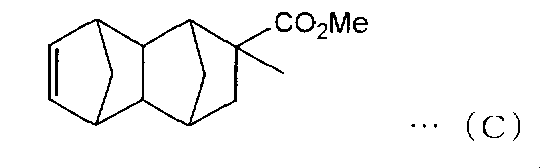
- spiro [fluorene-9,8′-tricyclo [4.3.0.1 2,5 ] [3] decene] (endo body) represented by the above structural formula (A) 90 g, represented by the following formula (C) 8- methoxycarbonyl-8-methyl-tetracyclo [4.4.0.1 2,5 .1 7,10] -3- dodecene 6.2 g, molecular weight regulator 0.419 g of 1-hexene and 18.6 g of toluene were charged into a nitrogen-substituted reaction vessel and heated to 80 ° C.
- Comparative Example 4 12.6 parts by weight of cellulose acetate propionate (referred to as compound A) having an acetyl group substitution degree of 0.1, a propionyl group substitution degree of 2.6 and a number average molecular weight of 75,000, and an average substitution degree of 2. 3.
- the glass transition temperature (Tg) of the obtained film was 147 ° C. (Stretching process) This film was stretched uniaxially by 2.0 times in a 155 ° C. air circulation drying oven using a stretching machine. (Shrinking process) The shrinking process was not performed.
- the stretched film is firstly dried in an air circulation drying oven at 113 ° C. (first shrinking process), then in an air circulation drying oven at 90 ° C. (second shrinking process), and further at 70 ° C.
- a retardation film was produced in the same manner as in Example 1 except that it was shrunk in an air circulation drying oven (third shrinking step).
- the present invention there is obtained a retardation film that does not cause the location dependence of a phase change even when it is placed for a long time under a high temperature condition in a state of being bonded to glass through an adhesive. be able to. Therefore, by using the retardation film of the present invention for a polarizing plate, a display device having excellent long-term reliability can be obtained in that display unevenness does not occur.
- Polarizing plate 300 Feeding part 310 Iodine aqueous solution bath 320 Bath of aqueous solution containing boric acid and potassium iodide 330 Including potassium iodide Aqueous bath 340 Drying means 350 Polarizer 360 Winding unit
Landscapes
- Physics & Mathematics (AREA)
- General Physics & Mathematics (AREA)
- Optics & Photonics (AREA)
- Engineering & Computer Science (AREA)
- Chemical & Material Sciences (AREA)
- Nonlinear Science (AREA)
- Mechanical Engineering (AREA)
- Mathematical Physics (AREA)
- Crystallography & Structural Chemistry (AREA)
- Manufacturing & Machinery (AREA)
- Materials Engineering (AREA)
- Health & Medical Sciences (AREA)
- Chemical Kinetics & Catalysis (AREA)
- Medicinal Chemistry (AREA)
- Polymers & Plastics (AREA)
- Organic Chemistry (AREA)
- Polarising Elements (AREA)
- Liquid Crystal (AREA)
- Shaping By String And By Release Of Stress In Plastics And The Like (AREA)
- Manufacture Of Macromolecular Shaped Articles (AREA)
Abstract
Description
0.70<Re1[450]/Re1[550]<0.97・・・(1)
1.5×10⁻³<Δn<6.0×10⁻³・・・(2)
(式中、Re1[450]およびRe1[550]は、それぞれ、23℃における波長450nmおよび550nmの光で測定した位相差フィルムの面内の位相差値であり、Δnは波長550nmの光で測定した位相差フィルムの面内の複屈折である)
を満たし、前記製造方法が、次の工程:
連続的に長尺の高分子フィルムを搬送して供給する工程、
前記高分子フィルムを搬送方向に対して横方向に延伸する延伸工程、
前記延伸工程後に、前記高分子フィルムを前記横方向に収縮させる第1収縮工程、及び、
前記第1収縮工程後に、前記高分子フィルムを前記横方向に収縮させる第2収縮工程
を有し、
前記第1収縮工程における収縮温度T1(℃)と前記第2収縮工程における収縮温度T2(℃)とが、下記式(3):
1<(T1-T2)≦10・・・(3)
を満たすことを特徴とする。
前記第2収縮工程後に、前記高分子フィルムを前記横方向に収縮させる第3収縮工程
をさらに有し、
前記第2収縮工程における収縮温度T2(℃)と前記第3収縮工程における収縮温度T3(℃)とが、下記式(4):
1<(T2-T3)≦10・・・(4)
を満たすことを特徴とする。
0≦(T0-T1)≦10・・・(5)
を満たすことを特徴とする。
(Tg-20)<T<(Tg+3)・・・(6)
(式中、Tgは前記高分子フィルムのガラス転移温度であり、TはT1、T2又はT3である)
を満たすことを特徴とする。
2°<(配向角の最大値-配向角の最小値)<10°・・・(7)
を満たすことを特徴とする。
|Re1[450]/Re1[550]-Re2[450]/Re2[550]|<0.02・・・(8)
(式中、Re1[450]およびRe1[550]は、それぞれ、23℃における波長450nmおよび550nmの光で測定した位相差フィルムの面内の位相差値であり、Re2[450]およびRe2[550]は、それぞれ、23℃における波長450nmおよび550nmの光で測定した、温度90℃で100時間熱処理した後の位相差フィルムの面内の位相差値である)
を満たすことを特徴とする。
0.70<Re1[450]/Re1[550]<0.97・・・(1)
1.5×10⁻³<Δn<6.0×10⁻³・・・(2)
|Re1[450]/Re1[550]-Re2[450]/Re2[550]|<0.02・・・(8)
(式中、Re1[450]およびRe1[550]は、それぞれ、23℃における波長450nmおよび550nmの光で測定した位相差フィルムの面内の位相差値であり、Δnは波長550nmの光で測定した位相差フィルムの面内の複屈折であり、Re2[450]およびRe2[550]は、それぞれ、23℃における波長450nmおよび550nmの光で測定した、温度90℃で100時間熱処理した後の位相差フィルムの面内の位相差値である)を満たすことを特徴とする。
2°<(配向角の最大値-配向角の最小値)<10°・・・(7)
を満たすことを特徴とする。
本発明の位相差フィルムは、一般に、高分子フィルムを延伸させて得られるものである。本明細書において、位相差フィルムは、面内及び/又は厚み方向に複屈折を有するものをいう。
本発明の位相差フィルムは、0.70<Re1[450]/Re1[550]<0.97の関係を満たすものである。
本発明の位相差フィルムのRe1[550]とRe1[450]の比(Re1[450]/Re1[550])は、好ましくは0.75~0.95である。Re1[450]/Re1[550]を上記の範囲とすることによって、例えば、上記位相差フィルムを表示パネル装置に用いた場合に、より一層優れた表示特性を得ることができる。
本発明の位相差フィルムは|Re1[450]/Re1[550]-Re2[450]/Re2[550]|<0.02の関係を満たすものである。好ましくは、本発明の位相差フィルムは、|Re1[450]/Re1[550]-Re2[450]/Re2[550]|<0.017、さらに好ましくは、|Re1[450]/Re1[550]-Re2[450]/Re2[550]|<0.015の関係を満たす。上記関係を満たさない場合、反射色相に色つきが生じ、ムラが発生する。
これら位相差フィルムの面内位相差値は、Axometrics社製 製品名「AxoScan」を用いて測定することができる。
本発明の位相差フィルムは、1.5×10⁻³<Δn<6.0×10⁻³の関係を満たすものである。
面内複屈折Δnは、好ましくは1.5×10⁻³~5.0×10⁻³であり、より好ましくは2.0×10⁻³~4.5×10⁻³である。上記位相差フィルムの製造における延伸工程に、固定端延伸、例えば横延伸工程や斜め延伸工程を含ませ、その延伸倍率、延伸温度及び延伸速度等を調整することによりΔnを上記の範囲とすることによって、従来に比べて広幅の位相差フィルムの製造が可能となり、大型ディスプレイへ対応が可能となり、材料の有効活用による低コスト設計も可能となる。場合によっては、延伸でよりΔnを調整しやすくするために、製膜条件、例えば温度、速度、厚みなどを、適宜変更することもある。Δnがこの範囲でない場合は、位相差発現性が悪くなり、広幅延伸ができなくなる。またΔnがこの範囲の場合は、適宜の位相差に調整することが容易となり、表示装置に合わせた位相差設計をすることで、正面特性や視野角特性の優れた表示装置を提供することができる。また、Δnがこの範囲の場合は、位相差フィルムの厚みを非常に薄く設計することが容易になり、薄型の表示装置に組み込むことも容易となる。逆にΔnがこの範囲より小さい場合は、フィルムの厚みを過度に大きくする必要が出てくる。
本発明の位相差フィルムは、高分子フィルムを延伸することによって、配向させて作製される。
具体的には、本発明の位相差フィルムの製造方法ではまず、連続的に長尺の高分子フィルムを搬送して供給し、この高分子フィルムを、搬送方向に対して横方向に延伸する。
<2.1.延伸工程>
上記高分子フィルムを延伸する方法としては、高分子フィルムの搬送方向に対して横方向に延伸することが可能であれば、目的に応じて、任意の適切な延伸方法が採用され得る。本発明に適した上記延伸方法としては、例えば、横一軸延伸方法、縦横同時二軸延伸方法、縦横逐次二軸延伸方法等が挙げられる。延伸する手段としては、テンター延伸機、二軸延伸機等々の、任意の適切な延伸機が用いられ得る。好ましくは、上記延伸機は、温度制御手段を備える。加熱して延伸を行う場合は、延伸機の内部温度は連続的に変化させてもよいし、段階的に変化させてもよい。工程は1回でも2回以上に分割してもいい。延伸方向はフィルム幅方向(TD方向)や斜め方向に延伸するのがよい。
本発明の位相差フィルムの製造方法ではさらに、多段(少なくとも2段階)の収縮工程が採用される。具体的には、本発明の位相差フィルムの製造方法によれば、上記延伸工程後に、高分子フィルムを延伸方向と反対向きに収縮させる第1収縮工程が行われ、さらに、この第1収縮工程後に、高分子フィルムを第1収縮工程の場合と同じ方向(上記横方向)に収縮させる第2収縮工程が行われる。
この収縮工程は、前記延伸工程において延伸フィルム内に溜まった収縮応力を緩和させるために行うものである。また、本発明で採用する収縮工程では、主鎖のみの緩和が行われると考えられ、側鎖は分子間相互作用により配向がより固定されるため、緩和が起こりにくい。その結果、長期安定性の向上が可能となると考えられる。
そして、本発明の位相差フィルムの製造方法では、前段の収縮工程とこれに続く後段の収縮工程との間の収縮温度の差が、所定の範囲内にあることとしている。すなわち、本発明の位相差フィルムの製造方法によれば、第1収縮工程における収縮温度T1(℃)と第2収縮工程における収縮温度T2(℃)とは、1<(T1-T2)≦10を満たす関係にある。さらには、1<(T1-T2)≦5を満たす関係にあるのが好ましい。
この場合において、第2収縮工程における収縮温度T2(℃)と第3収縮工程における収縮温度T3(℃)とは、1<(T2-T3)≦10を満たす関係にある。さらには、1<(T2-T3)≦5を満たす関係にあるのが好ましい。
本発明の位相差フィルムは、任意の適切な用途に用いられ得る。代表的な用途としては、液晶表示装置のλ/4板、λ/2板、光学補償フィルム等が挙げられる。この他には、液晶表示装置、有機ELディスプレイ、及びプラズマディスプレイ等のフラットパネルディスプレイ用反射防止フィルムが挙げられる。
本発明の位相差フィルムとしては、熱可塑性樹脂を主成分とする高分子フィルムの延伸フィルムを用いることができる。好ましくは、延伸配向性を有する主鎖と、260~380nmの吸収端を持つユニットからなる側鎖を有し、且つ、前記主鎖の伸びる方向に対して該側鎖の面が交差しているポリマーを主成分とする高分子、例えば共重合体からなる脂肪族性ポリマーの延伸フィルムが用いられる。より好ましくは、セルロース系樹脂や、ポリエステル系、ポリビニルアルコール系、ポリビニルアセタール系、ポリカーボネート系、ポリアミド系、ポリイミド系、ポリエーテルスルホン系、ポリエーテル系、ポリスルホン系、ポリスチレン系、ポリノルボルネン系、ポリオレフィン系、アクリル系、ウレタン系、アクリルウレタン系、アセテート系等の透明樹脂等の樹脂であって、主鎖方向に長い剛直な環構造や結晶性構造を作るセグメントが導入されており、吸収端波長が260nm~380nmである芳香族基を側鎖に持つ高分子量体を主成分とする高分子フィルムの延伸フィルムが用いられる。この高分子量体において、該セグメントや芳香族基は共重合されていてもブレンドされていてもよい。

当該ポリビニルアセタール系樹脂は、ポリビニルアルコール系樹脂と、2種類以上のアルデヒド、2種類以上のケトン、または少なくとも1種のアルデヒドと少なくとも1種のケトンを用い、縮合反応(アセタール化ともいう)によって得ることができる。下記一般式(II)で表される構造を含むポリビニルアセタール系樹脂を主成分とする高分子フィルムの延伸フィルムであれば、逆波長分散特性を示し、成形加工性、延伸性、位相差値の安定性に優れる位相差フィルムを得ることができる。また、延伸配向性にも優れるため、位相差フィルムの厚みを薄くすることができる。

上記重合体を含有する高分子フィルムは、任意の適切な成形加工法によって得ることができる。上記成形加工法としては、例えば、圧縮成形法、トランスファー成形法、射出成形法、押出成形法、ブロー成形法、粉末成形法、FRP成形法、ソルベントキャスティング法等が挙げられる。好ましくは、上記成形加工法は、ソルベントキャスティング法または押出成形法である。上記ソルベントキャスティング法は、具体的には、例えば、主成分となる重合体や添加剤を含む組成物を溶剤に溶解した濃厚溶液(ドープ)を、脱泡し、エンドレスステンレスベルトまたは回転ドラムの表面に、シート状に流延し、溶剤を蒸発させてフィルムを成形する方法である。また、上記押出成形法は、具体的には、例えば、主成分となる重合体や添加剤を含む組成物を加熱溶融し、これをTダイ等を用いて、キャスティングロールの表面にシート状に押出して、冷却させてフィルムを形成する方法である。上記の方法を採用することによって、厚み均一性に優れた高分子フィルムを得ることができる。
1つの実施形態において、本発明の偏光板は、上記位相差フィルムと偏光子とを少なくとも有する。図2は、本発明の好ましい実施形態において、位相差フィルムを偏光板に用いた場合の概略断面図である。図2(a)の偏光板は、偏光子1の一方の側に任意の保護層2を備え、他方の側に位相差フィルム4を備える。図2(b)の偏光板は、偏光子1の一方の側に光学フィルム3を備え、他方の側に位相差フィルム4を備える。図2(c)の偏光板は、偏光子1の一方の側に任意の保護層2を備え、他方の側に任意の保護層2’を備え、該保護層2’の該偏光子1を備える側とは反対の側に、さらに位相差フィルム4を備える。図2(d)の偏光板は、偏光子1の両側に光学フィルム3及び3’を備え、該光学フィルム3’の該偏光子1を備える側とは反対の側に、さらに位相差フィルム4を備える。
上記任意の保護層2及び2’は、それぞれ同一であってもよいし、異なっていてもよい。また、上記光学フィルム3及び3’は、それぞれ同一であってもよいし、異なっていてもよい。
上記保護層は、透明で、色付きが無いことが好ましい。具体的には、厚み方向の位相差が、好ましくは-90nm~+90nmであり、さらに好ましくは-80nm~+80nmであり、最も好ましくは-70nm~+70nmである。
上記保護層の厚みとしては、上記の好ましい厚み方向の位相差が得られる限りにおいて、任意の適切な厚みが採用され得る。具体的には、保護層の厚みは、好ましくは100μm以下であり、さらに好ましくは80μm以下であり、特に好ましくは40μm以下である。
1つの実施形態において、本発明の表示パネル装置は、上記偏光板と液晶表示パネルや有機EL表示パネルといった表示パネルを有する。偏光板と表示パネルは直接接着されていてもよいし、タッチパネルや他の光学部材といった任意の部材を介して配置されていてもよい。
(1)組成比の測定:
核磁気共鳴スペクトルメーター[日本電子(株)製 製品名「LA400」](測定溶媒;重DMSO、周波数;400MHz、観測核;1H、測定温度;70℃)を用いて求めた。
(2)厚みの測定方法:
厚みが10μm未満の場合、薄膜用分光光度計[大塚電子(株)製 製品名「瞬間マルチ測光システム MCPD-2000」]を用いて測定した。厚みが10μm以上の場合、アンリツ製デジタルマイクロメーター「KC-351C型」を使用して測定した。
(3)フィルムの屈折率の測定方法:
アッベ屈折率計[アタゴ(株)製 製品名「DR-M4」]を用いて、23℃における波長450nm及び550nmの光で測定した屈折率より求めた。
(4)位相差値(Re、Rth)の測定方法:
[Axometrics社製 製品名「AxoScan」]を用いて23℃の室内で測定した。
(5)透過率の測定方法:
分光光度計[村上色彩技術研究所(株)製 製品名「DOT-3」]を用いて、23℃における波長550nmの光で測定した。
(6)ガラス転移温度の測定
示差走査熱量計[セイコー(株)製 製品名「DSC-6200」]を用いて、JIS K 7121(1987)(プラスチックの転移温度の測定方法)に準じた方法により求めた。具体的には、5mgのフィルムサンプルを、窒素雰囲気下(ガスの流量;80ml/分)で昇温(加熱速度;10℃/分)させて2回測定し、2回目のデータを採用した。
(7)収縮率
[(延伸後の最大チャック間距離)-(収縮による収縮後のテンターチャック間距離)]/(延伸後の最大チャック間距離)*100を収縮率とした。
(8)配向角
上記位相差値の測定と同様の手法により、配向角を測定した。
配向角の測定は面内で最低3点以上測定を行い、最大値と最小値とした。
配向角は測定装置の基準方向と位相差フィルムの遅相軸方向とのなす角度である。
(9)波長分散
上記位相差値の測定と同様の手法により、波長分散変化を測定した。
[Axometrics社製 製品名「AxoScan」]を用いて波長450nmと波長550nmの位相差を測定し、測定波長450nmの位相差R(450)を測定波長550nmの位相差R(550)で割り、波長分散値を求めた。
(10)波長分散変化
上記、波長分散値を測定したサンプルを粘着剤を用いてガラス板に貼り合せ、90℃の恒温槽に100時間投入した。100時間経過後のサンプルを同様に測定して波長分散値を求め、100℃に加熱する前の波長分散値との変化量を求めた。
(11)ムラ評価
(11-1)[表示パネル装置の作製]
実施例および比較例において得られた位相差フィルムの各々と偏光板[日東電工社製 商品名「NPF TEG1465DUHC」](粘着剤層を除いた層厚みが112μm))とを位相差フィルムの遅相軸と偏光子の吸収軸が45度となるように、アクリル系粘着剤(20μm)を介して貼り合わせることにより円偏光板を作成した。この円偏光板を同アクリル系粘着剤(20μm)を介して有機ELパネル[LGディスプレイ社製 商品名「15EL9500」])の視認側に貼り合わせて表示パネル装置を作成した。
(11-2)[表示パネル装置の加熱試験]
加熱試験の前に、表示装置パネルの表示画面上の45点の色度(反射色相)を分光測色計(コニカミノルタセンシング(株)製 商品名「CM-2600d」)により測定した。測定点は、表示画面上を均一に縦、横にそれぞれ5、9分割してつくられた45分割されたエリアの中心部分とした。また、表示画面全体の反射色の均一性を目視により評価した。その後、この表示パネル装置を、90℃の恒温オーブン中に100時間保管(加熱試験)した後、同様に表示画面上の45点の色度を測定した。更に、表示画面全体の反射色の均一性を目視により評価した。
8.8gのポリビニルアルコール系樹脂〔日本合成化学(株)製 商品名「NH-18」(重合度=1800、ケン化度=99.0%)〕を、105℃で2時間乾燥させた後、167.2gのジメチルスルホキシド(DMSO)に溶解した。ここに、2.98gの2-メトキシ-1-ナフトアルデヒド及び0.80gのp-トルエンスルホン酸・1水和物を加えて、40℃で1時間攪拌した。反応溶液に、3.18gのベンズアルデヒドを加え、40℃で1時間攪拌した後、4.57gのジメチルアセタールをさらに加えて、40℃で3時間攪拌した。その後、2.13gのトリエチルアミンを加えて反応を終了させた。得られた粗生成物は、1Lのメタノールで再沈殿を行った。ろ過した重合体をテトラヒドロフランに溶解し、再びメタノールで再沈殿を行った。これを、ろ過、乾燥して、11.9gの白色の重合体を得た。この重合体は、1H-NMRで測定したところ、下記式(III)で表される繰り返し単位を有し、l:m:n:oの比率(モル比)は10:25:52:11であった。また、重合体のガラス転移温度(Tg)は、130℃であった。

上記重合体を、メチルエチルケトン(MEK)に溶解し、ポリエチレンテレフタレートフィルム(厚み70μm)上にアプリケーターで塗工し、130℃の空気循環式乾燥オーブンで乾燥させた後、ポリエチレンテレフタレートフィルムから剥ぎ取って、厚み135μmのフィルムを作製した。
(延伸工程)
このフィルムを延伸機にて、130℃の空気循環式乾燥オーブン内で2.1倍に横一軸延伸した。
(収縮工程)
延伸したフィルムを、まず131℃の空気循環式乾燥オーブン内で(第1収縮工程)、次に126℃の空気循環式乾燥オーブン内で(第2収縮工程)、さらに121℃の空気循環式乾燥オーブン内で(第3収縮工程)、収縮させた。収縮率は3%であった。
収縮率を5%としたことを除き、実施例1と同様の方法で位相差フィルムを作製した。
第3収縮工程を省略したことを除き、実施例1と同様の方法で位相差フィルムを作製した。収縮率は5%であった。
8.8gのポリビニルアルコール系樹脂〔日本合成化学(株)製 商品名「NH-18」(重合度=1800、ケン化度=99.0%)〕を、105℃で2時間乾燥させた後、167.2gのジメチルスルホキシド(DMSO)に溶解した。ここに、2.98gの2-メトキシ-1-ナフトアルデヒド及び0.80gのp-トルエンスルホン酸・1水和物を加えて、40℃で1時間攪拌した。反応溶液に、3.18gのベンズアルデヒドを加え、40℃で1時間攪拌した後、10.4gの2,2-ジメトキシプロパンをさらに加えて、40℃で3時間攪拌した。その後、2.13gのトリエチルアミンを加えて反応を終了させた。得られた粗生成物は、1Lのメタノールで再沈殿を行った。ろ過した重合体をテトラヒドロフランに溶解し、再びメタノールで再沈殿を行った。これを、ろ過、乾燥して、18.8gの白色の重合体を得た。この重合体は、1H-NMRで測定したところ、下記式(V)で表される繰り返し単位を有し、l:m:n:oの比率(モル比)は13:31:43:13であった。また、重合体のガラス転移温度(Tg)は、133℃であった。

上記重合体を、メチルエチルケトン(MEK)に溶解し、ポリエチレンテレフタレートフィルム(厚み70μm)上にアプリケーターで塗工し、130℃の空気循環式乾燥オーブンで乾燥させた後、ポリエチレンテレフタレートフィルムから剥ぎ取って、厚み170μmのフィルムを作製した。
(延伸工程)
このフィルムを延伸機にて、130℃の空気循環式乾燥オーブン内で2.1倍に横一軸延伸し、延伸フィルムを作製した。
(収縮工程)
延伸したフィルムを、実施例1の場合と同一の第1収縮工程、第2収縮工程及び第3収縮工程により、収縮させた。収縮率は5%であった。
ジメチルアセタールに代えて、8.81gのアセトアルデヒドを加え、2-メトキシ-1-ナフトアルデヒドの使用量を2.89gとしたこと以外は、実施例1と同様の方法で、11.7gの白色の重合体を得た。この重合体は、1HNMRで測定したところ、下記式(IV)で表される繰り返し単位を有し、l:m:n:oの比率(モル比)は11:54:28:7であった。また、重合体のガラス転移温度(Tg)は、126℃であった。

上記重合体を、メチルエチルケトン(MEK)に溶解し、ポリエチレンテレフタレートフィルム(厚み70μm)上にアプリケーターで塗工し、空気循環式乾燥オーブンで乾燥させた後、ポリエチレンテレフタレートフィルムから剥ぎ取って、厚み95μmのフィルムを作製した。
(延伸工程)
このフィルムを延伸機にて、130℃の空気循環式乾燥オーブン内で2.5倍倍に横一軸延伸し、延伸フィルムを作製した。
(収縮工程)
延伸したフィルムを、実施例1の場合と同一の第1収縮工程、第2収縮工程及び第3収縮工程により、収縮させた。収縮率は5%であった。
シクロヘキサンジメタノール(CHDM)67.35部、9,9-ビス(4-ヒドロキシ-3-メチルフェニル)フルオレン(BCF)90.94部、ジフェニルカーボネート154.61部、及び触媒としてテトラメチルアンモニウムヒドロキシド1.8×10⁻²部と水酸化ナトリウム1.6×10⁻⁴部を窒素雰囲気下180℃に加熱し溶融させた。その後、30分かけて減圧度を13.4kPaに調整した。その後、60℃/時間の速度で260℃まで昇温を行い、10分間その温度で保持した後、1時間かけて減圧度を133Pa以下とした。合計6時間撹拌下で反応を行った。
次に、(株)テクノベル製15mmφ二軸押出機に幅150mm、リップ幅500μmTダイとフィルム引き取り装置を取り付け、得られたコポリカーボネートをフィルム成形することにより厚みが120μmの透明な押出しフィルムを得た。
(延伸工程)
このフィルムを延伸機にて、126℃の空気循環式乾燥オーブン内で2.1倍に横一軸延伸し、延伸フィルムを作製した。
(収縮工程)
延伸したフィルムを、まず116℃の空気循環式乾燥オーブン内で(第1収縮工程)、次に111℃の空気循環式乾燥オーブン内で(第2収縮工程)、さらに106℃の空気循環式乾燥オーブン内で(第3収縮工程)、収縮させた。収縮率は5%であった。


上記重合体を塩化メチレンに溶解し、ポリエチレンテレフタレートフィルム(厚み:70μm)上にアプリケ―タで塗工し、80℃の空気循環式乾燥オープンで乾燥させた後、ポリエチレンテレフタレートフィルムから剥ぎ取って、厚み155μmのフィルムを作製した。
(延伸工程)
このフィルムを延伸機にて、190℃の空気循環式乾燥オーブン内で2.0倍に横一軸延伸した。
(収縮工程)
延伸したフィルムを、まず184℃の空気循環式乾燥オーブン内で(第1収縮工程)、次に174℃の空気循環式乾燥オーブン内で(第2収縮工程)、さらに164℃の空気循環式乾燥オーブン内で(第3収縮工程)、収縮させた。収縮率は5%であった。
8.8gのポリビニルアルコール系樹脂〔日本合成化学(株)製 商品名「NH-18」(重合度=1800、ケン化度=99.0%)〕を、105℃で2時間乾燥させた後、167.2gのジメチルスルホキシド(DMSO)に溶解した。ここに、2.98gの2-メトキシ-1-ナフトアルデヒド及び0.80gのp-トルエンスルホン酸・1水和物を加えて、40℃で1時間攪拌した。反応溶液に、3.18gのベンズアルデヒドを加え、40℃で1時間攪拌した後、4.57gのジメチルアセタールをさらに加えて、40℃で3時間攪拌した。その後、2.13gのトリエチルアミンを加えて反応を終了させた。得られた粗生成物は、1Lのメタノールで再沈殿を行った。ろ過した重合体をテトラヒドロフランに溶解し、再びメタノールで再沈殿を行った。これを、ろ過、乾燥して、11.9gの白色の重合体を得た。この重合体は、1H-NMRで測定したところ、下記式(XI)で表される繰り返し単位を有し、l:m:n:oの比率(モル比)は10:25:52:11であった。また、示差走査熱量計により、この重合体のガラス転移温度(Tg)を測定したところ、130℃であった。

上記重合体を、メチルエチルケトン(MEK)に溶解し、ポリエチレンテレフタレートフィルム(厚み70μm)上にアプリケーターで塗工し、空気循環式乾燥オーブンで乾燥させた後、ポリエチレンテレフタレートフィルムから剥ぎ取って、厚み135μmのフィルムを作製した。
(延伸工程)
このフィルムを延伸機にて、135℃の空気循環式乾燥オーブン内で2.1倍に横一軸延伸した。
(収縮工程)
収縮工程は、行わなかった。
収縮工程として、延伸したフィルムを、135℃の空気循環式乾燥オーブン内で収縮させたこと(第1収縮工程のみ)を除き、比較例1と同様の方法で位相差フィルムを作製した。フィルムの収縮率は1%であった。
5.0gのポリビニルアルコール系樹脂[日本合成化学(株)製 商品名「NH-18」(重合度;1800、ケン化度;99.0%)]を105℃で2時間乾燥させた後、95mlのジメチルスルホシキド(DMSO)に溶解した。ここに、2.02gの2,4,6-トリメチルベンズアルデヒド(メシトアルデヒド)、および0.44gのp-トルエンスルホン酸・1水和物を加えて、40℃で2時間攪拌した。これに、13.41gの1,1-ジエトキシエタン(アセタール)を加え、さらに40℃で2時間攪拌した。その後、1.18gのトリエチルアミンを加え、反応を終了した。得られた反応生成物(ポリマー)を、メタノール溶液に滴下し、再沈殿を行った。このポリマーを沈降させ、上澄み液をデカンテーションで除去した後、さらに、メタノール/水=1/1(体積/体積)を加えて、該ポリマーを洗浄した。これをろ過して得られたポリマーを乾燥させて、7.50gの白色ポリマーを得た。上記白色ポリマーは、1H-NMRにより測定したところ、下記式(VI)に示す構造(l:m:n=21:58:21)のポリビニルアセタール系樹脂であった。また、示差走査熱量計により、この重合体のガラス転移温度(Tg)を測定したところ、120℃であった。

上記重合体をトルエンに溶解し、ポリエチレンテレフタレートフィルム(厚み:70μm)上にアプリケ―タで塗工し、130℃の空気循環式乾燥オープンで乾燥させた後、ポリエチレンテレフタレートフィルムから剥ぎ取って、厚み240μmのフィルムを作製した。
(延伸工程)
このフィルムを延伸機にて、123℃の空気循環式乾燥オーブン内で2.0倍に横一軸延伸した。
(収縮工程)
収縮工程は、行わなかった。
アセチル基の置換度が0.1、プロピオニル基の置換度が2.6、数平均分子量75000であるセルロースアセテートプロピオネート(化合物Aとする)を12.6重量部、平均置換度が2.3、数平均分子量が51000であるエチルセルロースを0.4重部(以下化合物Bとする)、塩化メチレン87重量部を含むドープを調製した。
(製膜工程)
このドープを室温23℃、湿度15%の環境下で、長辺方向に1.0×10⁶N/m2の応力を付与した状態の厚み125μmの二軸延伸PETフィルム上の長辺方向が流延方向となるように流延した後、室温で4分間、60℃で4分間、80℃で4分間乾燥を行った。得られたフィルムをPETフィルムから剥離した後、さらに流延方向に2.0×105N/m2の応力を付与した状態で110℃にて30分乾燥し厚さ220μmのポリマーフィルムを得た。得られたフィルムのガラス転移温度(Tg)は147℃であった。
(延伸工程)
このフィルムを延伸機にて、155℃の空気循環式乾燥オーブン内で2.0倍に横一軸延伸した。
(収縮工程)
収縮工程は、行わなかった。
収縮工程として、延伸したフィルムを、まず113℃の空気循環式乾燥オーブン内で(第1収縮工程)、次に90℃の空気循環式乾燥オーブン内で(第2収縮工程)、さらに70℃の空気循環式乾燥オーブン内で(第3収縮工程)、収縮させたことを除き、実施例1と同様の方法で位相差フィルムを作製した。
上記実施例1~9および比較例1~5で得られた位相差フィルムについて、波長分散性(Re1[450]/Re1[550])、面内複屈折(Δn)、Nz係数を測定するとともに、波長分散変化及びムラについて、評価を行った。測定及び評価結果を表1に示す。

2、2’ 任意の保護層
3、3’ 光学フィルム
4 位相差フィルム
11 偏光板
300 繰り出し部
310 ヨウ素水溶液浴
320 ホウ酸とヨウ化カリウムとを含む水溶液の浴
330 ヨウ化カリウムを含む水溶液浴
340 乾燥手段
350 偏光子
360 巻き取り部
Claims (11)
- 位相差フィルムの製造方法であって、該位相差フィルムが下記式(1)及び(2):
0.70<Re1[450]/Re1[550]<0.97・・・(1)
1.5×10⁻³<Δn<6.0×10⁻³・・・(2)
(式中、Re1[450]およびRe1[550]は、それぞれ、23℃における波長450nmおよび550nmの光で測定した位相差フィルムの面内の位相差値であり、Δnは波長550nmの光で測定した位相差フィルムの面内の複屈折である)
を満たし、前記製造方法が、次の工程:
連続的に長尺の高分子フィルムを搬送して供給する工程、
前記高分子フィルムを搬送方向に対して横方向に延伸する延伸工程、
前記延伸工程後に、前記高分子フィルムを前記横方向に収縮させる第1収縮工程、及び、
前記第1収縮工程後に、前記高分子フィルムを前記横方向に収縮させる第2収縮工程
を有し、
前記第1収縮工程における収縮温度T1(℃)と前記第2収縮工程における収縮温度T2(℃)とが、下記式(3):
1<(T1-T2)≦10・・・(3)
を満たす、前記製造方法。 - 前記製造方法が、次の工程:
前記第2収縮工程後に、前記高分子フィルムを前記横方向に収縮させる第3収縮工程
をさらに有し、
前記第2収縮工程における収縮温度T2(℃)と前記第3収縮工程における収縮温度T3(℃)とが、下記式(4):
1<(T2-T3)≦10・・・(4)
を満たす、請求項1に記載の製造方法。 - 前記延伸工程における延伸温度T0(℃)と前記第1収縮工程における収縮温度T1(℃)とが、下記式(5):
0≦(T0-T1)≦10・・・(5)
を満たす、請求項1又は2に記載の製造方法。 - 前記第1収縮工程における収縮温度T1(℃)、前記第2収縮工程における収縮温度T2(℃)、及び前記第3収縮工程における収縮温度T3(℃)が、下記式(6):
(Tg-20)<T<(Tg+3)・・・(6)
(式中、Tgは前記高分子フィルムのガラス転移温度であり、TはT1、T2又はT3である)
を満たす、請求項1~3のいずれか1項に記載の製造方法。 - 請求項1~3のいずれか1項に記載の製造方法により得られる位相差フィルムであって、下記式(7):
2°<(配向角の最大値-配向角の最小値)<10°・・・(7)
を満たす、請求項1~4に記載の位相差フィルム。 - 請求項1~5のいずれか1項に記載の製造方法により得られる位相差フィルムであって、下記式(8):
|Re1[450]/Re1[550]-Re2[450]/Re2[550]|<0.02・・・(8)
(式中、Re1[450]およびRe1[550]は、それぞれ、23℃における波長450nmおよび550nmの光で測定した位相差フィルムの面内の位相差値であり、Re2[450]およびRe2[550]は、それぞれ、23℃における波長450nmおよび550nmの光で測定した、温度90℃で100時間熱処理した後の位相差フィルムの面内の位相差値である)
を満たす、前記位相差フィルム。 - 下記式(1)、(2)及び(8)を満たす、位相差フィルム。
0.70<Re1[450]/Re1[550]<0.97・・・(1)
1.5×10⁻³<Δn<6.0×10⁻³・・・(2)
|Re1[450]/Re1[550]-Re2[450]/Re2[550]|<0.02・・・(8)
(式中、Re1[450]およびRe1[550]は、それぞれ、23℃における波長450nmおよび550nmの光で測定した位相差フィルムの面内の位相差値であり、Δnは波長550nmの光で測定した位相差フィルムの面内の複屈折であり、Re2[450]およびRe2[550]は、それぞれ、23℃における波長450nmおよび550nmの光で測定した、温度90℃で100時間熱処理した後の位相差フィルムの面内の位相差値である) - 下記式(7)
2°<(配向角の最大値-配向角の最小値)<10°・・・(7)
を満たす、請求項7に記載の位相差フィルム。 - 延伸配向性を有する主鎖と、260~380nmで吸収端を持つユニットからなる側鎖を有し、且つ、前記主鎖の伸びる方向に対して該側鎖の面が交差しているポリマーを主成分とする高分子を含む、請求項7又は8に記載の位相差フィルム。
- 請求項7~9のいずれか1項に記載の位相差フィルムと、偏光子とを備える、偏光板。
- 請求項10に記載の偏光板を備える、表示装置。
Priority Applications (4)
| Application Number | Priority Date | Filing Date | Title |
|---|---|---|---|
| CN201380011264.0A CN104169752B (zh) | 2012-02-27 | 2013-01-10 | 相位差膜及其制造方法、偏振片、以及显示装置 |
| KR1020147023575A KR101729230B1 (ko) | 2012-02-27 | 2013-01-10 | 위상차 필름 및 그 제조 방법, 편광판, 및 표시장치 |
| KR1020167027149A KR102002456B1 (ko) | 2012-02-27 | 2013-01-10 | 위상차 필름 및 그 제조 방법, 편광판, 및 표시장치 |
| US14/381,159 US9389352B2 (en) | 2012-02-27 | 2013-01-10 | Retardation film and production method therefor, polarizing plate, and display device |
Applications Claiming Priority (2)
| Application Number | Priority Date | Filing Date | Title |
|---|---|---|---|
| JP2012-040499 | 2012-02-27 | ||
| JP2012040499A JP5995160B2 (ja) | 2012-02-27 | 2012-02-27 | 位相差フィルム及びその製造方法、偏光板、及び表示装置 |
Publications (1)
| Publication Number | Publication Date |
|---|---|
| WO2013128954A1 true WO2013128954A1 (ja) | 2013-09-06 |
Family
ID=49082164
Family Applications (1)
| Application Number | Title | Priority Date | Filing Date |
|---|---|---|---|
| PCT/JP2013/050279 WO2013128954A1 (ja) | 2012-02-27 | 2013-01-10 | 位相差フィルム及びその製造方法、偏光板、及び表示装置 |
Country Status (6)
| Country | Link |
|---|---|
| US (1) | US9389352B2 (ja) |
| JP (1) | JP5995160B2 (ja) |
| KR (2) | KR101729230B1 (ja) |
| CN (2) | CN106873067B (ja) |
| TW (1) | TWI529427B (ja) |
| WO (1) | WO2013128954A1 (ja) |
Families Citing this family (7)
| Publication number | Priority date | Publication date | Assignee | Title |
|---|---|---|---|---|
| JP2013076982A (ja) * | 2011-09-14 | 2013-04-25 | Mitsubishi Chemicals Corp | 位相差フィルム、並びにこれを用いた円偏光板及び画像表示装置 |
| CN105658410B (zh) * | 2013-10-30 | 2017-11-24 | 日本瑞翁株式会社 | 长条拉伸膜及其制造方法 |
| JP6049600B2 (ja) * | 2013-11-29 | 2016-12-21 | 住友化学株式会社 | 偏光子及びそれを含む偏光板 |
| KR102444610B1 (ko) | 2015-12-02 | 2022-09-27 | 삼성전자주식회사 | 반사방지 필름 및 이를 포함하는 유기 발광 표시 장치 |
| KR102097802B1 (ko) * | 2017-08-10 | 2020-04-06 | 삼성에스디아이 주식회사 | 액정표시장치 |
| JP7281881B2 (ja) * | 2018-07-31 | 2023-05-26 | 住友化学株式会社 | 水平配向液晶硬化膜およびこれを含む積層体 |
| CN111913248B (zh) * | 2020-07-27 | 2022-03-29 | 明基材料有限公司 | 相位差膜、圆偏光板以及含该圆偏光板的电激发光显示器 |
Citations (5)
| Publication number | Priority date | Publication date | Assignee | Title |
|---|---|---|---|---|
| JP2006117792A (ja) * | 2004-10-21 | 2006-05-11 | Kaneka Corp | 新規なポリイミドフィルム |
| JP2007161994A (ja) * | 2005-11-21 | 2007-06-28 | Nitto Denko Corp | ナフチル基を有する重合体を含有する光学フィルム |
| WO2012077663A1 (ja) * | 2010-12-06 | 2012-06-14 | 日東電工株式会社 | 位相差フィルム、偏光板、および表示パネル装置 |
| WO2013039178A1 (ja) * | 2011-09-14 | 2013-03-21 | 三菱化学株式会社 | 位相差フィルム、並びにこれを用いた円偏光板及び画像表示装置 |
| WO2013039179A1 (ja) * | 2011-09-14 | 2013-03-21 | 三菱化学株式会社 | 位相差フィルム、並びにこれを用いた円偏光板及び画像表示装置 |
Family Cites Families (25)
| Publication number | Priority date | Publication date | Assignee | Title |
|---|---|---|---|---|
| JP2846418B2 (ja) | 1990-06-27 | 1999-01-13 | エーザイ株式会社 | ナフタレン誘導体 |
| EP0482620B1 (en) | 1990-10-24 | 1997-03-05 | Nitto Denko Corporation | Birefringent film, process for producing the same, retardation film, elliptically polarizing plate, and liquid crystal display |
| JPH09110775A (ja) | 1995-10-20 | 1997-04-28 | Mitsui Toatsu Chem Inc | 1−ナフトアルデヒドの製造方法 |
| AU2001248832A1 (en) * | 2000-04-25 | 2001-11-07 | Bayer A.G. | Optical film |
| US6937308B2 (en) * | 2002-07-26 | 2005-08-30 | Eastman Kodak Company | In-plane switching liquid crystal display with compensation film |
| JP2006011361A (ja) * | 2004-05-28 | 2006-01-12 | Sekisui Chem Co Ltd | 位相差フィルム |
| CN100579993C (zh) | 2004-07-16 | 2010-01-13 | 日东电工株式会社 | 相位差膜及其用途以及新型改性聚合物 |
| JP2006058540A (ja) * | 2004-08-19 | 2006-03-02 | Jsr Corp | 光学フィルム、偏光板および液晶ディスプレイ |
| TW200624447A (en) | 2004-11-25 | 2006-07-16 | Sekisui Chemical Co Ltd | Retardation film |
| CN100489576C (zh) | 2004-11-25 | 2009-05-20 | 积水化学工业株式会社 | 相位差薄膜 |
| JP3851919B2 (ja) * | 2004-12-20 | 2006-11-29 | 日東電工株式会社 | 液晶パネルおよび液晶表示装置 |
| JP4618675B2 (ja) * | 2005-02-08 | 2011-01-26 | 日東電工株式会社 | 位相差フィルム、偏光素子、液晶パネルおよび液晶表示装置 |
| US8697201B2 (en) | 2005-03-31 | 2014-04-15 | Kaneka Corporation | Retardation film and production method thereof |
| TWI400282B (zh) * | 2005-09-12 | 2013-07-01 | Fujifilm Corp | 醯化纖維素薄膜之製法、偏光板及液晶顯示器 |
| CN100587526C (zh) | 2005-11-21 | 2010-02-03 | 日东电工株式会社 | 含有具有萘基的聚合物的光学薄膜 |
| JP2007147884A (ja) * | 2005-11-25 | 2007-06-14 | Nitto Denko Corp | 液晶表示装置 |
| KR100904124B1 (ko) | 2006-05-29 | 2009-06-24 | 닛토덴코 가부시키가이샤 | 액정 패널 및 액정 표시 장치 |
| TWI406899B (zh) * | 2006-09-05 | 2013-09-01 | Tosoh Corp | Optical compensation film and phase difference film |
| JP2009086651A (ja) | 2007-09-11 | 2009-04-23 | Toray Ind Inc | 位相差フィルム、円偏光板、およびこれを用いた表示装置 |
| JP5706071B2 (ja) | 2009-03-26 | 2015-04-22 | 帝人株式会社 | 位相差フィルム |
| WO2010064721A1 (ja) | 2008-12-05 | 2010-06-10 | 帝人化成株式会社 | 光学フィルム |
| JP2010134232A (ja) | 2008-12-05 | 2010-06-17 | Teijin Chem Ltd | 光学フィルム |
| JP2010271860A (ja) | 2009-05-20 | 2010-12-02 | Yukiko Ikebe | チャート、該チャートの作成方法及びチャート表示システム |
| JP5552361B2 (ja) * | 2010-05-13 | 2014-07-16 | 株式会社カネカ | 延伸フィルム及び延伸フィルムの製造方法、並びに位相差板 |
| JP6404707B2 (ja) | 2014-01-06 | 2018-10-10 | 日東電工株式会社 | アクリル系粘着剤組成物、アクリル系粘着剤層、粘着剤層付き基材フィルム、積層体、及び画像表示装置 |
-
2012
- 2012-02-27 JP JP2012040499A patent/JP5995160B2/ja active Active
-
2013
- 2013-01-10 KR KR1020147023575A patent/KR101729230B1/ko active IP Right Review Request
- 2013-01-10 CN CN201610974017.6A patent/CN106873067B/zh active Active
- 2013-01-10 US US14/381,159 patent/US9389352B2/en active Active
- 2013-01-10 CN CN201380011264.0A patent/CN104169752B/zh active Active
- 2013-01-10 WO PCT/JP2013/050279 patent/WO2013128954A1/ja active Application Filing
- 2013-01-10 KR KR1020167027149A patent/KR102002456B1/ko active IP Right Grant
- 2013-01-14 TW TW102101351A patent/TWI529427B/zh active
Patent Citations (5)
| Publication number | Priority date | Publication date | Assignee | Title |
|---|---|---|---|---|
| JP2006117792A (ja) * | 2004-10-21 | 2006-05-11 | Kaneka Corp | 新規なポリイミドフィルム |
| JP2007161994A (ja) * | 2005-11-21 | 2007-06-28 | Nitto Denko Corp | ナフチル基を有する重合体を含有する光学フィルム |
| WO2012077663A1 (ja) * | 2010-12-06 | 2012-06-14 | 日東電工株式会社 | 位相差フィルム、偏光板、および表示パネル装置 |
| WO2013039178A1 (ja) * | 2011-09-14 | 2013-03-21 | 三菱化学株式会社 | 位相差フィルム、並びにこれを用いた円偏光板及び画像表示装置 |
| WO2013039179A1 (ja) * | 2011-09-14 | 2013-03-21 | 三菱化学株式会社 | 位相差フィルム、並びにこれを用いた円偏光板及び画像表示装置 |
Also Published As
| Publication number | Publication date |
|---|---|
| CN106873067A (zh) | 2017-06-20 |
| US9389352B2 (en) | 2016-07-12 |
| CN106873067B (zh) | 2019-10-18 |
| KR20160118383A (ko) | 2016-10-11 |
| TWI529427B (zh) | 2016-04-11 |
| KR20140125401A (ko) | 2014-10-28 |
| KR102002456B1 (ko) | 2019-07-23 |
| US20150029587A1 (en) | 2015-01-29 |
| JP5995160B2 (ja) | 2016-09-21 |
| JP2013174815A (ja) | 2013-09-05 |
| TW201335638A (zh) | 2013-09-01 |
| CN104169752B (zh) | 2016-12-07 |
| KR101729230B1 (ko) | 2017-04-21 |
| CN104169752A (zh) | 2014-11-26 |
Similar Documents
| Publication | Publication Date | Title |
|---|---|---|
| JP2018032044A (ja) | 位相差フィルム、偏光板、および表示パネル装置 | |
| JP5995160B2 (ja) | 位相差フィルム及びその製造方法、偏光板、及び表示装置 | |
| JP3984277B2 (ja) | ナフチル基を有する重合体を含有する光学フィルム | |
| JP4618675B2 (ja) | 位相差フィルム、偏光素子、液晶パネルおよび液晶表示装置 | |
| KR101058971B1 (ko) | 위상차 필름, 광학 적층체, 액정 패널 및 액정 표시 장치 | |
| US7807239B2 (en) | Optical film containing polymer having naphtyl group | |
| WO2014021151A1 (ja) | 位相差フィルムの製造方法 | |
| JP4693094B2 (ja) | 位相差フィルムの製造方法 | |
| JP4721858B2 (ja) | 位相差フィルムの製造方法 | |
| TW202244121A (zh) | 相位差膜、使用該相位差膜之圓偏光板及圖像顯示裝置 |
Legal Events
| Date | Code | Title | Description |
|---|---|---|---|
| 121 | Ep: the epo has been informed by wipo that ep was designated in this application |
Ref document number: 13754353 Country of ref document: EP Kind code of ref document: A1 |
|
| ENP | Entry into the national phase |
Ref document number: 20147023575 Country of ref document: KR Kind code of ref document: A |
|
| WWE | Wipo information: entry into national phase |
Ref document number: 14381159 Country of ref document: US |
|
| NENP | Non-entry into the national phase |
Ref country code: DE |
|
| 122 | Ep: pct application non-entry in european phase |
Ref document number: 13754353 Country of ref document: EP Kind code of ref document: A1 |