WO2011118835A1 - 分注装置 - Google Patents
分注装置 Download PDFInfo
- Publication number
- WO2011118835A1 WO2011118835A1 PCT/JP2011/057705 JP2011057705W WO2011118835A1 WO 2011118835 A1 WO2011118835 A1 WO 2011118835A1 JP 2011057705 W JP2011057705 W JP 2011057705W WO 2011118835 A1 WO2011118835 A1 WO 2011118835A1
- Authority
- WO
- WIPO (PCT)
- Prior art keywords
- bottle
- dispensing
- pressing
- chemical
- tube
- Prior art date
- Legal status (The legal status is an assumption and is not a legal conclusion. Google has not performed a legal analysis and makes no representation as to the accuracy of the status listed.)
- Ceased
Links
Images


Classifications
-
- A—HUMAN NECESSITIES
- A61—MEDICAL OR VETERINARY SCIENCE; HYGIENE
- A61J—CONTAINERS SPECIALLY ADAPTED FOR MEDICAL OR PHARMACEUTICAL PURPOSES; DEVICES OR METHODS SPECIALLY ADAPTED FOR BRINGING PHARMACEUTICAL PRODUCTS INTO PARTICULAR PHYSICAL OR ADMINISTERING FORMS; DEVICES FOR ADMINISTERING FOOD OR MEDICINES ORALLY; BABY COMFORTERS; DEVICES FOR RECEIVING SPITTLE
- A61J3/00—Devices or methods specially adapted for bringing pharmaceutical products into particular physical or administering forms
- A61J3/002—Compounding apparatus specially for enteral or parenteral nutritive solutions
Definitions
- the present invention relates to a dispensing device.
- Patent Document 1 discloses a dispensing device in which a plurality of chemical liquid bottles are mounted on a circular mounting body in plan view along the circumferential direction, and a chemical liquid is injected into each chemical liquid bottle via a nozzle. Is described.
- the chemical liquid stored in the chemical liquid bottle is a suspension
- the solid particles gradually dispersed in the liquid with time will become non-uniform, so it is necessary to agitate and homogenize before dispensing There is.
- the chemical liquid is agitated by sucking the chemical liquid in the chemical liquid bottle using the nozzle and returning the sucked chemical liquid into the chemical liquid bottle again.
- Patent Document 1 requires a separate storage chamber so that a sufficient amount of chemical solution can be sucked from the chemical solution bottle through the nozzle so that stirring can be performed appropriately.
- the object of the present invention is to provide a dispensing device that can sufficiently stir the chemical solution in the chemical solution bottle in a short time despite the simple configuration.
- Dispensing device A chemical solution that supports the plurality of chemical solution bottles so that a plurality of chemical solution bottles arranged in an annular region on substantially the same circumference moves along the circumferential direction of the annular region, and moves to a dispensing position of the annular region.
- This configuration makes it possible to sufficiently agitate the contained chemical solution in a short time despite the simple configuration of rotating the chemical solution bottle.
- the bottle support portion supports the plurality of chemical liquid bottles so as to be rotatable toward the inside of the annular region.
- the dead space inside the annular region in which the chemical liquid bottle is arranged can be used for the rotation of the chemical liquid bottle, and the small size of the dispensing device despite the configuration including a plurality of chemical liquid bottles. Can be realized.
- the bottle support section includes a first inclined position where the liquid bottle position is higher than a center position of the bottom surface of the chemical liquid bottle from a horizontal position, and a second inclined position symmetrical to the first inclined position with respect to the horizontal plane. It is preferable to oscillate within the rotation range.
- the chemical solution in the chemical solution bottle can be agitated in a short time, and the workability can be improved.
- the bottle support portion includes a plurality of rotation support portions, Each said rotation support part supports the said chemical
- This configuration makes it possible to rotate the chemical bottles supported by the plurality of rotation support portions with respect to one rotation drive portion, so that the configuration can be simplified and manufactured at low cost.
- the chemical liquid bottle is a bottomed cylindrical shape with a mouth formed at the upper end,
- the bottle support part preferably holds the mouth part and rotatably supports the chemical liquid bottle.
- the rotation range of the chemical bottle by the rotation drive unit includes a mounting position where the chemical bottle can be mounted on the bottle support unit with the mouth portion positioned above.
- This configuration makes it possible to smoothly attach and detach the chemical solution bottle.
- a closed portion that is provided in the bottle support portion and closes the mouth portion of the chemical liquid bottle; an air supply nozzle that extends through the closed portion toward the bottom surface of the chemical liquid bottle; and a chemical bottle that penetrates the closed portion. It is preferable to further include a chemical solution extraction portion having a chemical solution extraction nozzle that opens to the mouth portion.
- This configuration allows the chemical solution in the chemical solution bottle to be sufficiently stirred and then dispensed through the chemical solution dispensing unit.
- the bottle support part supports the chemical liquid bottle upside down so that the mouth part is on the lower side when the chemical liquid is poured out.
- This configuration makes it possible to smoothly dispense the chemical solution from the chemical solution bottle using the gravity acting on the chemical solution.
- the chemical liquid dispensing nozzle is composed of a flexible tube extending from the chemical liquid bottle, It is preferable to further include a chemical solution discharging mechanism for discharging the chemical solution in the chemical solution bottle into the patient bottle by making contact with and separating from the tube extending from the chemical solution bottle moved to the extraction position of the annular region. .
- This structure can further simplify the structure and can be manufactured at low cost.
- the chemical solution discharging mechanism is A first pressing member that crushes the tube and closes the flow path; A second pressing member that moves while pressing the tube from the upstream side in the flow direction of the chemical solution toward the pressing position rather than the pressing position by the first pressing member; When changing the pressing position with respect to the tube by the second pressing member, an interlocking member that releases the pressing state by the first pressing member and enables the chemical solution in the tube to flow, Should be provided.
- the medicinal solution bottle is attached to the medicinal solution dispensing portion at the mouth, It is preferable that the said chemical
- This configuration allows the chemical solution bottle to be attached to and detached from the bottle support portion with the chemical solution dispensing portion attached in advance to the mouth portion, so that workability can be greatly improved. Moreover, there is no fear that the chemical solution in the chemical solution bottle leaks during the attaching / detaching operation.
- the drug solution dispensing part is a plug member attached to the mouth part of the drug solution bottle, It is preferable that the plug member includes a bottle fastener that slides to be engaged with a bulging portion formed in the mouth portion and supports the drug solution bottle.
- This configuration makes it possible to attach the chemical solution dispensing portion to the mouth portion of the chemical solution bottle with a simple bottle stopper that can be simply slid.
- the bottle fastener is slidable so as to be engaged with a bulging portion formed in the mouth portion in a state where the chemical solution bottle is disposed at an appropriate position with respect to the plug member.
- the mouth portion of the chemical liquid bottle is formed with a male screw at the tip than the bulging portion, It is preferable that the chemical liquid dispensing portion is formed with a female screw into which a mouth portion of the chemical liquid bottle is screwed.
- a cleaning water supply unit that supplies cleaning water to each nozzle of the chemical solution dispensing unit included in the chemical solution bottle moved to the cleaning position of the annular region, and air is supplied to each nozzle that has moved to the drying position of the annular region It is preferable to further include a nozzle cleaning unit having an air supply unit.
- the cleaning water can be supplied and the waste water after cleaning can be collected in the cleaning water recovery unit simply by moving the chemical bottle to the cleaning position in the circumferential direction of the annular region. Furthermore, it can dry with the air supplied from an air supply part.
- the washing water supply unit is disposed below the annular region. In particular, it is preferable to arrange in the dead space of the apparatus main body.
- the air supply unit is disposed below the annular region. In particular, it is preferable to arrange in the dead space of the apparatus main body.
- the internal space of the apparatus main body can be used more efficiently, and the apparatus main body can be downsized.
- a diluent tank containing the diluent is further provided, A pivot arm that movably supports an injection tube extending from the diluent tank; The injection port of the injection tube is positioned at an injection position between the patient bottle located at the dispensing position and the drug solution bottle positioned above the patient bottle, and at a separated position away from the patient bottle.
- the pivot arm is preferably pivotable.
- the dilution liquid can be easily supplied into the patient bottle by simply rotating the injection tube with the rotation arm without moving the patient bottle or complicating the configuration. be able to.
- the chemical liquid dispensing part attached to the mouth part of each chemical liquid bottle includes a detected part that stores position information indicating which bottle support part is mounted, Before pouring the liquid medicine from the liquid medicine bottle containing the liquid medicine to be dispensed into the bottle for the patient, authentication is performed based on the position information stored in the detected part. It is preferable to further comprise a control means.
- a storage means When the chemical solution bottle is attached to the bottle support part, the control means stores the positional information stored in the detected part and the chemical information stored in the chemical liquid bottle to which the chemical liquid dispensing part having the detected part is attached. Are preferably stored in the storage means in association with each other.
- the position information and the chemical information can be associated with each other, so that different chemical solutions are not accidentally dispensed in the subsequent dispensing process.
- a bottle for a patient that collects a liquid medicine poured out from the liquid medicine dispensing section is placed, and a bottle placement section that can be raised and lowered,
- a bottle detection unit capable of specifying the position of the mouth of the patient bottle placed on the bottle placement unit;
- Control means for adjusting the position of the patient bottle relative to the drug solution dispensing unit by raising and lowering the bottle mounting unit based on positional information of the mouth of the patient bottle detected by the bottle detection unit; Is preferably further provided.
- the position of the mouth can be specified by the bottle detection unit, and the patient bottle can be automatically moved up and down to a position where it can be dispensed from the drug solution dispensing unit. it can.
- the chemical liquid dispensed from the chemical liquid dispensing unit is less likely to spill.
- the bottle mounting unit includes a weight detection unit that can detect the weight of a patient bottle to be mounted, including a drug solution to be filled, It is preferable that the control means controls a dispensing amount by the drug solution dispensing unit based on a weight of the patient bottle detected by the weight detection unit.
- the first dispensing process of dispensing the chemical solution by the first dispensing amount per unit time and the chemical solution before the unit time It is preferable to further comprise control means for executing a second dispensing process for dispensing each second dispensing amount that is smaller than the first dispensing amount.
- the drug solution is poured into the patient bottle in two stages, ie, the first and second dispensing processes.
- One of the dispensing processes is preferably performed by opening and closing a flow path from the chemical solution bottle to the patient bottle.
- This configuration makes it possible to freely change the dispensing amount while allowing easy and inexpensive production.
- One end opening is connected to the mouth of the drug solution bottle and extends downward, and a flexible tube capable of supplying the drug solution into the patient bottle through the other end opening;
- a first pressing member that can move to a closed position that blocks the flow of the chemical liquid that passes therethrough by pressing and deforming the tube, and an open position that permits the flow of the chemical liquid by releasing the pressure on the tube; , A closed position movable to the downstream side while maintaining a state of blocking the flow of the chemical liquid passing by pressing and deforming the tube on the upstream side of the pressing position by the first pressing member, and to the tube
- a second pressing member that is movable to an open position that releases the pressing of the liquid and allows the flow of the chemical liquid;
- the control means executes a maximum dispensing process for positioning the first pressing member and the second pressing member at an open position as the first dispensing process.
- the chemical solution can be quickly dispensed until immediately before the dispensing process is completed, and the efficient dispensing process can be executed.
- One of the dispensing processes is preferably performed by moving the pressing position of the flow path from the chemical solution bottle to the patient bottle toward the downstream side in the flow direction of the chemical solution.
- This configuration makes it possible to dispense a certain amount of chemical solution by moving the tube pressing position.
- One end opening is connected to the mouth of the drug solution bottle and extends downward, and a flexible tube capable of supplying the drug solution into the patient bottle through the other end opening;
- a first pressing member that can move to a closed position that blocks the flow of the chemical liquid that passes therethrough by pressing and deforming the tube, and an open position that permits the flow of the chemical liquid by releasing the pressure on the tube; , A closed position movable to the downstream side while maintaining a state of blocking the flow of the chemical liquid passing by pressing and deforming the tube on the upstream side of the pressing position by the first pressing member, and to the tube
- a second pressing member that is movable to an open position that releases the pressing of the liquid and allows the flow of the chemical liquid; With The control means moves the first pressing member to the open position from the state where the first pressing member and the second pressing member are positioned at the closed position as the second dispensing process, and moves the second pressing member to the open position.
- the chemical solution stored in the tube partitioned by the first pressing member and the second pressing member located at the closed position is moved by moving the closed position to the downstream side while maintaining the state of blocking the flow of the chemical solution passing therethrough. It is preferable to execute a small-volume dispensing process for performing small-volume dispensing that can be supplied to the patient bottle any number of times.
- Pressure detecting means for directly or indirectly detecting the air pressure in the chemical bottle; It is preferable that the control means controls the air supply amount by the air supply unit based on the detection result of the pressure detection means.
- This configuration prevents the amount of drug solution supplied to the patient bottle from increasing per unit time and causing weight detection errors. Further, even when a chemical solution having a high viscosity is stored in the chemical solution bottle, the air pressure is small and cannot be discharged. Furthermore, it is possible to detect whether air leakage has occurred.
- the control means may control the air supply amount by the air supply unit based on the detection result of the pressure detection means so that the air pressure in the chemical liquid bottle is constant.
- the control means controls the air supply amount by the air supply unit based on the detection result of the pressure detection means so that the flow rate per unit time of the chemical liquid dispensed from the chemical liquid bottle is constant. May be.
- the control unit may control an air supply amount by the air supply unit so that a pressure detected by the pressure detection unit in the second extraction process is smaller than that in the first extraction process. .
- the control means may control the amount of air supplied by the air supply unit such that the higher the viscosity of the chemical liquid stored in the chemical liquid bottle, the higher the pressure detected by the pressure detection means. Good.
- the middle of the flow path for supplying air into the chemical bottle is composed of at least two flow paths with different amounts of air that can be supplied per unit time.
- the air pressure in the chemical solution bottle can be adjusted with a simple and inexpensive configuration in which the flow path is switched, and a good dispensing state of the chemical solution can be realized.
- a guide member having a guide groove for guiding the tube in an arc shape;
- the second pressing member preferably includes a second pressing portion that moves along the guide groove to press the tube and block the flow of the chemical solution.
- This configuration makes it possible to block the flow of the chemical solution in the tube even while moving the second pressing portion.
- the first pressing member is attached to the guide member so as to be rotatable about a first support shaft, and a first pressing portion capable of pressing the tube, and the tube is pressed by the first pressing portion.
- An urging section for urging It is preferable that the second pressing member includes a cam member that operates the first pressing member while maintaining a closed state in which the tube flow path is blocked by the second pressing portion.
- the second pressing member is provided to be rotatable around a second support shaft, A driving member for driving the second pressing member; It is preferable that the control means drives the second pressing member in the normal direction by the driving member and executes the small amount dispensing process.
- a single drive member dispenses a small amount of liquid to the patient bottle every time the tube is stored, and the tube is opened to continuously supply the liquid from the chemical bottle to the patient bottle.
- the maximum dispensing process can be executed, and the configuration can be simplified, downsized, and manufactured at low cost.
- the control means includes In the small volume dispensing process, the second pressing member is driven by the driving member, the first pressing portion of the first pressing member, and the storage position in which the chemical solution is stored in the tube by the second pressing portion; 2 A small amount pouring position where the pressing portion is moved to the downstream side while maintaining the pressing state, and the pressing state of the tube by the first pressing portion of the first pressing member is released by the cam member, and the tube by the second pressing portion Is performed by recirculating and moving the tube at the preparation position for resuming the pressing state of the tube by the first pressing portion.
- the second pressing member is driven by the driving member to release the pressing state by the second pressing portion, and the first pressing portion of the first pressing member is separated from the tube by the cam member. It may be executed by maintaining the open state.
- One end opening is connected to the mouth of the drug solution bottle and extends downward, and a flexible tube capable of supplying the drug solution into the patient bottle through the other end opening;
- a guide member having a guide groove for guiding the tube in an arc shape;
- a closed position that can move downstream while maintaining the state of blocking the flow of the chemical liquid that passes through by pressing and deforming the tube, and an open that allows the chemical liquid flow by releasing the pressure on the tube
- a pressing member having a pair of pressing parts movable to a position;
- the control means presses and deforms the tube by the pair of pressing portions, partitions the inside of the tube by the pair of pressing portions, stores the chemical solution, and the pair of pressing portions
- a small amount dispensing process for sequentially discharging the stored chemical solution is performed by circularly moving the part, and the tube is opened by separating the pair of pressing parts from the tube as the first dispensing process.
- the maximum dispensing process for continuously discharging the chemical solution may be performed.
- the tube can be fully opened until a desired dispensing amount is reached, and then a certain amount of the chemical solution stored in the tube can be supplied. That is, by finely adjusting the amount of the chemical solution supplied to the patient bottle immediately before reaching the desired dispensing amount, accurate dispensing can be performed while simplifying the configuration and manufacturing at low cost.
- the bottle support portion supports each chemical solution bottle upside down in the annular region so that the mouth portion of the chemical solution bottle is located on the lower side,
- the rotation drive unit is movable to a forward position where the bottle support unit can be operated and a retracted position separated from the bottle support unit, It is preferable that an attachment / detachment space in which the chemical solution bottle rotated by the rotation driving unit is located below the advance position.
- the space for attaching / detaching can be made sufficiently wide, and the attaching / detaching operation of the chemical solution bottle can be performed smoothly.
- the bottle support portion supports each chemical solution bottle upside down in the annular region so that the mouth portion of the chemical solution bottle is located on the lower side, A mouth part of the chemical liquid bottle, a closing part for closing the mouth part of the chemical liquid bottle, an air supply nozzle extending through the closed part to the bottom surface side of the chemical liquid bottle, and a chemical liquid bottle penetrating the closing part And a flexible tube that opens to the mouth of A chemical solution discharge mechanism for discharging the chemical solution in the chemical solution bottle into the patient bottle by contacting and separating from the tube,
- the chemical solution discharge mechanism can be moved to a forward position where the chemical solution can be dispensed by making contact with and separating from the tube, and a backward position separated from the dispensing position, It is preferable to arrange an extraction space in which a patient bottle can be placed below the advance position.
- the dispensing space can be made sufficiently wide and the patient bottle can be placed and taken out smoothly.
- the chemical solution in the chemical solution bottle can be rapidly and sufficiently agitated despite the simple configuration in which the bottle support portion is driven to rotate the chemical solution bottle.
- FIG. 2 is a schematic plan view showing the internal structure of FIG. 1 (the chemical bottle is rotated to a horizontal position).
- FIG. 1 the chemical bottle is rotated to a horizontal position.
- FIG. 1 the chemical bottle is rotated to a horizontal position.
- FIG. 1 the chemical bottle is rotated to a horizontal position.
- FIG. 1 the chemical bottle is rotated to a horizontal position.
- FIG. 1 the chemical bottle is rotated to a horizontal position.
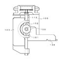
- FIG. 2 is a schematic partial front view which shows the support structure of the cyclic
- FIG. the chemical
- FIG. 8 is a plan view of FIG. 7. It is a schematic side view which shows the structure of the rotation support part of FIG. It is a schematic plan view which shows the bottle support part of FIG. It is a schematic front view which shows the dilution water injection
- FIG. 1 It is a schematic plan view of the dispensing apparatus which concerns on 2nd Embodiment. It is a partially broken side view which shows the bottle support part of FIG. It is a figure which shows the state which rotated the cam member and the 2nd press member counterclockwise from the state shown in FIG. It is a figure which shows the state which rotated the cam member and the 2nd press member further counterclockwise from FIG. It is a top view of the action
- FIG. 30 is a perspective view showing a support base of the lock mechanism and the rotation support portion of FIG. 29. It is a perspective view which shows the state which added the rotation part to FIG. It is a perspective view which shows the rotation drive part of FIG. It is a perspective view which shows the state which looked at FIG. 32 from the other side.
- FIG. 37 is a bottom view of the plug body of FIG. 36. It is a perspective view which shows the moving member provided in the extraction
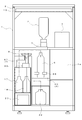
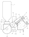
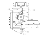
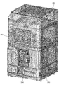
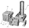
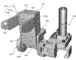
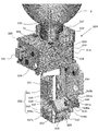
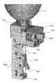
- (First embodiment) 1 and 2 show a dispensing apparatus according to the first embodiment.
- the dispensing device includes a bottle support portion 3 that rotatably supports a plurality of chemical liquid bottles 2 on a substantially rectangular parallelepiped device main body 1, and each bottle support portion 3.
- Rotation drive unit 4 for rotating the drug solution bottle 2, drug solution dispensing unit 5 for dispensing the drug solution stored in each drug solution bottle 2, and dilution water for injecting dilution water into the patient bottle 6
- An injection unit 7, a nozzle cleaning unit 8 for cleaning the nozzles used in the chemical solution dispensing unit 5, and a control device 9 for driving and controlling these components are provided.
- the apparatus main body 1 has a substantially rectangular parallelepiped frame shape, and the surface is covered with a panel.
- a holding plate 10 on which the control device 9 is arranged is attached to the upper part of the apparatus main body 1.
- the holding plate 10 can be pulled forward together with the first front panel 12 along an extendable support rail 11 extending in the front-rear direction.
- the holding plate 10 is rotatably connected to the support rail 11 on both sides of the rear end portion, and can be rotated downward by grasping a handle 10a provided at the front end portion.
- the control device 9 attached to the holding plate 10 can be exposed to the front surface, and operations such as maintenance can be easily performed.
- a second front panel 13 is disposed below the first front panel 12.
- the second front panel 13 is attached to the apparatus main body 1 in FIG. 1 so as to be openable and closable around the right end as a rotation center, and can be opened and closed by grasping the handle 13a at the left end.
- a bottle support portion 3, a rotation drive portion 4, and the like which will be described later, are disposed.
- the second front panel 13 is provided with a display 14 composed of a liquid crystal touch panel or the like, and a payout opening 13b through which paper printed by the journal printer 15 is discharged is formed on the side of the display 14.
- a first drawer 16 is provided in the upper left part of the lower area of the second front panel 13, and a dilution water tank 17 and a washing water tank 18 are disposed there. Yes.
- the first drawer 16 can be pulled forward by pulling the handle 16 a and can be poured into the dilution water tank 17 and the washing water tank 18.
- a discharge port 19 through which a label printed by the label printer 20 is discharged is formed below the first drawer 16.
- a bottle mounting portion 60 is provided on the upper side so that the patient bottle 6 can be placed and the medicine from the drug solution dispensing portion 5 can be injected as will be described later. It has been.
- a second drawer 21 is provided below the bottle mounting unit 60, and a waste liquid recovery tank 22 is disposed there.
- the second drawer 21 can be withdrawn forward by pulling the handle 21a to discard the waste liquid.
- an open / close door 23 (FIG. 1) is provided so as to be rotatable around the right edge.
- the open / close door 23 can be opened and closed by grasping a handle 23a provided at the left center portion.
- a storage chamber 24 capable of storing the patient bottle 6 and the like is formed.
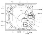
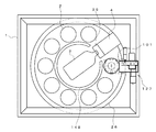
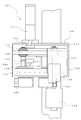
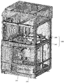
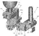
- the bottle support portion 3 supports an annular support 26 on a support plate 25 provided in the apparatus main body 1, and further, a plurality of rotation support portions 27 (see FIG. 6).
- the support plate 25 is formed with an opening 28 in the center, and interference when a chemical bottle 2 described later rotates is avoided.
- the support plate 25 is provided with a first guide roller 29a and a second guide roller 29b respectively disposed at four locations on the same circumference, a drive motor 32 having a drive gear 31 on a rotating shaft, and an encoder 33. It has been.
- the annular support 26 is formed by connecting inner edges of annular plates 34 a, 34 b arranged vertically at a predetermined interval by a plurality of connecting rails 35.
- the lower annular plate 34b includes a ring portion 36 and a gear portion 37 that is disposed on the lower side of the ring portion 36 and has a smaller diameter than the ring portion 36.
- the upper annular plate 34a is guided by a guide roller 30 that can roll on its upper surface.
- the lower annular plate 34b is rotatably supported by the ring portion 36 being supported by the first guide roller 29a and the second guide roller 29b at four locations (8 locations in total) on the outer peripheral surface and the annular lower surface. ing.
- a drive gear 31 provided on the rotation shaft of the drive motor 32 is engaged with the gear portion 37.
- the drive gear 31 is biased toward the gear portion 37, but can be separated from the gear portion 37 by operating the operation portion 31 a connected by a wire.
- the rotation of the annular support 26 is detected by the encoder 33 so that the position of the chemical bottle 2 supported by which rotating support 27 can be specified.
- the control device 9 which will be described later controls the rotation of the drive motor 32 based on the detection signal from the encoder 33, rotates the annular support 26, and places the chemical liquid bottle 2 supported by the rotation support portion 27 at a desired position ( (Moving position, pouring position, cleaning position, drying position).
- the encoder 33 can be dispensed with.
- the rotation range of the annular support 26 is a range of one rotation each in the forward and reverse directions.
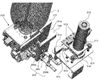
- the rotation support portion 27 includes a support base 38 that is removably attached to the ring portion 36 of the lower annular plate 34b by screwing or the like, and a support shaft 39a centered on the support base 38. And a rotating part 39 connected rotatably.
- the support base 38 is provided with a first pinch valve 40.
- the first pinch valve 40 is configured by a substantially L-shaped drive arm 41 provided so as to be rotatable about a support shaft 41a, and one end side thereof further extends vertically upward.
- the drive arm 41 swings between the clamping position and the release position by rotating the arm cam 43 by driving the arm motor 42, and can be positioned at one of these two positions and one of these intermediate positions. It has become.
- the first pinch valve 40 clamps a first nozzle 51 (to be described later) to deform the shape, and the flow path is fully closed to prevent the outflow of the chemical solution.
- the flow rate of the chemical solution that is, the discharge amount can be limited to almost half. It should be noted that the deformation amount of the first nozzle 51 by the first pinch valve 40 can be adjusted in multiple steps or steplessly.
- the rotating portion 39 is obtained by integrating the bottle mounting portion 45 with the rotating portion main body 44.
- the chemical solution bottle 2 can be attached to and detached from the bottle mounting portion 45.
- the chemical liquid bottle 2 has a bottomed cylindrical shape, and its cross-sectional area gradually decreases toward the top end 46.
- a support recess 47 is formed in the central portion of the bottle mounting portion 45.
- the mouth 46 of the chemical liquid bottle 2 is detachably attached to the support recess 47.
- at least a portion (bottom surface) with which the mouth portion 46 of the chemical liquid bottle 2 abuts is made of an elastic material such as rubber.
- the rotation member 39 is provided with a locking member 48.
- the locking member 48 is locked to a male screw portion 46 a formed on the outer peripheral surface of the mouth portion 46, and maintains the mouth portion 46 in pressure contact with the bottom surface of the support recess 47.
- the rotating portion 39 is attached to a substantially semicircular driven gear portion 49 on a support shaft provided in the rotating portion main body 44, and this driven gear portion 49 is driven by the rotating drive portion 4 described later. It is possible to rotate between an attachment position that is meshed with the gear portion 58 and turned upside down and an attachment / detachment position that is rotated 180 degrees and the mouth portion 46 is positioned above. As shown in FIG. 8, the rotating portion 39 is rotated between the mounting position and the attaching / detaching position. As shown in FIG. 8, the operation piece 36b provided integrally is an optical sensor 50 including a light emitting element and a light receiving element provided at each position. Judgment is made based on whether or not the optical path is interrupted.
- a first nozzle 51 and a second nozzle 52 made of a flexible resin material pass through the support recess 47, respectively.
- One end of the first nozzle 51 protrudes from the bottom surface of the support recess 47 by a predetermined dimension and is located near the mouth 46 of the chemical bottle 2, and the other end protrudes from the bottle mounting part 45 by a predetermined dimension downward.
- one end side of the second nozzle 52 extends to the vicinity of the bottom surface of the chemical liquid bottle 2 to be attached.
- the other end side of the 2nd nozzle 52 is pinched by the said drive arm 41, and the outflow of the chemical
- the other end portion of the second nozzle 52 extends to a side portion of the rotating portion 39 via the tube 52a, and is opposed to an air nozzle 73a, which will be described later, so as to be able to contact and separate.
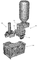
- the rotation drive unit 4 is attached to a mounting base 53 attached to the support plate 25, and drives the first motor 54 to advance and retract the ball screw 57 through the pulleys 55 a and 55 b and the belt 56.
- the drive gear portion 58 can reciprocate.
- the drive gear unit 58 meshes with the driven gear unit 49 of the rotating unit 39 at the forward movement position.
- the drive gear part 58 rotates forward / reversely via the gear which is not illustrated by the drive of the 2nd motor 59, and rotates the rotation part 39 between an attachment position and an attachment / detachment position.
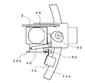
- the medicinal solution dispensing unit 5 includes a bottle placing unit 60 for placing the patient bottle 6 filled with the dispensed medicinal solution, and a second nozzle 52 in the medicinal solution bottle 2.
- the air supply part 61 which can supply air via is provided.
- the bottle mounting unit 60 includes a mounting plate 64 that moves up and down by driving the second lifting motor 62 and operating the lifting ball screw 63 via the pulleys 62a and 62b and the belt 62c.
- the weight of the patient bottle 6 placed on the placement plate 64 can be detected by the weight detection sensor 65.
- a pair of clamping pieces 66 is provided above the mounting plate 64. As shown in FIG. 10, each holding piece 66 is formed with a hold surface 66a having a concave facing surface and a guide surface 66b spaced from the hold surface 66a toward the front end side.
- the sandwiching pieces 66 are guided by four guide rods 67 so that they can be opened and closed, and interlocking gears 69 are engaged with racks 68 provided respectively.
- each clamping piece 66 opens and closes in conjunction. Moreover, each clamping piece 66 is urged
- the mouth portion 46 of the patient bottle 6 placed on the placement plate 64 is detected by a lift position detection sensor 70 (FIG. 9).
- the driving of the second lifting / lowering motor 62 is controlled by the control device 9 described later based on a detection signal from the lifting / lowering position detection sensor 70.
- the patient bottle 6 can be positioned at the initial position, the chemical solution injection position where the chemical solution can be injected from the first nozzle 51, and the dilution water injection position by the dilution water injection unit 7 described later. .
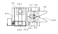
- the air supply unit 61 includes an elevating plate 72 that moves up and down between a connection position and a separated position by driving the first elevating motor 71 and rotating a cam 71a provided on the rotation shaft thereof.
- An air nozzle 73 a extending from the pump 73 is connected to the elevating plate 72.
- the air nozzle 73a is connected to the second nozzle 52 by raising the elevating plate 72 to the connection position. Then, by driving the pump 73, air is supplied into the chemical liquid bottle 2, and the stored chemical liquid is forcibly discharged from the first nozzle 51 with the air pressure.
- medical solution extraction from the 1st nozzle 51 may not be forced discharge using an air pressure, and you may make it discharge
- a separate opening / closing valve is provided at a predetermined location (for example, a lower end opening facing the air nozzle 73a) of the tube 52a, and the air nozzle 73a is connected when the lifting plate 72 is raised, and the lifting plate 72 contacts the opening / closing valve to open / close.
- the valve may be opened so that the connection of the air nozzle 73a is released when the elevating plate 72 is lowered, and the elevating plate 72 is separated from the on / off valve to close the on / off valve.
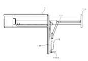
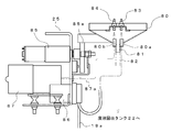
- the dilution water injecting section 7 is for injecting cleaning water contained in a dilution water tank 17 (FIG. 2) provided on the lower side of the apparatus body 1 into the patient bottle 6. is there.
- the dilution water injection part 7 includes an injection tube 74, a swing support part 75, and a swing arm 76 provided on the swing support part 75 so as to be rotatable about a support shaft 76a.
- the injection tube 74 is inserted into a dilution water tank 17 provided at one end on the lower side of the apparatus main body 1, passes through the rotation arm 76 from the swing support portion 75, and the other end is a lower surface of the distal end of the rotation arm 76.
- the injection port 76b is located in the position.
- the swing support portion 75 is provided with a first tube pump 77 and a rotation motor 78.
- the first tube pump 77 acts on the injection tube 74 and discharges the cleaning water stored in the dilution water tank 17 from the injection port 76 b on the distal end side of the rotating arm 76.
- the rotation motor 78 rotates the rotation arm 76 through the gears 78a and 78b by driving.
- the rotation range of the rotation arm 76 is detected by the sensor 76c, and is positioned at the water pouring position and the retreat position.
- a second pinch valve 79 is provided on the distal end side of the rotating arm 76 so as to be able to block the flow of cleaning water that passes through the injection tube 74 in pressure contact therewith.
- the second pinch valve 79 is controlled to be opened and closed by a drive motor and a cam (not shown).
- the nozzle cleaning unit 8 includes a cleaning dish 80 attached to a support plate 25 provided in the apparatus main body 1 so as to be movable up and down.
- the washing dish 80 has a substantially inverted conical shape, and a waste water port 81 is formed at the center of the bottom surface, and a waste water tube 82 extending to the waste liquid recovery tank 22 is connected thereto.
- a cleaning nozzle 83 and an air supply nozzle 84 are connected to the cleaning dish 80 through through holes 80a and 80b formed at two locations around the waste water outlet 81, respectively.
- a vertical movement motor 85, a second tube pump 86, and a compressor 87 are attached to the support plate 25.
- a cam 85a is integrated with the rotary shaft of the vertical movement motor 85, and the washing dish 80 can be moved up and down via the cam 85a.
- One end of the second tube pump 86 acts on the tube 18a inserted in the cleaning water tank 18, and the cleaning water stored in the cleaning water tank 18 is ejected from the cleaning nozzle 83 through the tube 18a.
- the compressor 87 ejects air from the air supply nozzle 84 via the tube 87a.
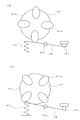
- control device 9 includes a control unit 88 and a storage unit 89.
- the control unit 88 refers to the data stored in the storage unit 89 on the basis of prescription data input from the server 90 via a LAN or the like and input signals from the sensors.
- the chemical liquid bottle 2 mounted on the bottle mounting portion 45 is rotated by driving and controlling the components, and the chemical liquid bottle 2 is rotated to agitate the stored chemical liquid.
- a series of dispensing processes such as pouring the chemical solution into the bottle 6, diluting the chemical solution with dilution water, washing the first nozzle 51, and drying are controlled.
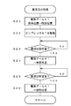
- the medicinal solution bottle 2 filled with the medicine (the first medicine when there are a plurality of medicines) included in the prescription data is specified (step S2).
- the chemical liquid bottle 2 is mounted on each rotation support portion 27 of the bottle support portion 3 in advance, the medicine to be stored and the rotation support portion 27 to be mounted are associated with each other. This is performed based on the data stored in the storage unit 89.
- step S3 it is determined whether or not stirring is required before the contained chemical solution is dispensed. This determination uses data stored in the storage unit 89 in advance as information (chemical solution information) regarding the chemical solution stored in the chemical solution bottle 2. If it is determined that the agitation is necessary, the rotation support portion 27 to which the corresponding chemical liquid bottle 2 is attached is positioned at the rotation position by driving the drive motor 32 and rotating the annular support body 26 ( Step S4). Then, by driving the first motor 54 of the rotation drive unit 4, the drive gear 58 is advanced and meshed with the driven gear unit 49 of the rotation support unit 27 (step S5).
- step S6 the rotation support portion 27 is rotated, and the chemical liquid bottle 2 attached thereto is moved between the attachment position and the attachment / detachment position (step S6).
- the rotation direction of the chemical liquid bottle 2 is the inside of the chemical liquid bottle 2 arranged on substantially the same circumference, that is, a dead space where no parts are arranged. Therefore, the chemical solution in the chemical solution bottle 2 can be agitated without increasing the size of the apparatus. And since the chemical
- step S7 A patient bottle 6 to be poured out by an operator in advance is set at the dispensing position.
- the patient bottle 6 may be set by automatically selecting an appropriate size and displaying it on the display 14 based on the prescription data.
- the mouth 46 is detected by the detection sensor, and the second elevating motor 62 is driven and controlled based on this detection signal, so that the placing plate 64 is moved up and down to raise the patient bottle 6. Is positioned at the dispensing standby position (step S8), and the chemical solution dispensing process is started (step S9).
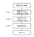
- the arm motor 42 is driven to press-contact the second nozzle 52 to rotate the drive arm 41 from the clamping position to the open position (step S21). Then, the first nozzle 51 is fully opened (step S22). Further, the compressor 87 is driven to supply air into the chemical liquid bottle 2 (step S23), and the internal pressure is increased, thereby smoothing out the chemical liquid.
- the first nozzle 51 is fully opened and air is supplied into the chemical liquid bottle 2 to determine how much chemical liquid is discharged per unit time for each chemical bottle containing different types of chemical liquids.
- a database is prepared in advance by experiments or the like and stored in the storage unit 89. And based on this database, the chemical
- step S24 Thereafter, by reaching the set amount before reaching the desired amount of the chemical solution (step S24), the drive arm 41 is rotated to the intermediate position (step S25), and the amount of the dispensed chemical solution is suppressed.
- the chemical liquid becomes a desired amount determined by the prescription data (the volume of the chemical liquid converted from the weight based on the specific gravity of the chemical liquid).
- Step S26 the drive arm 41 is rotated to the clamping position, and the dispensing of the chemical solution is stopped (Step S27).
- step S10 it is determined whether or not the diluting water needs to be poured. If it is determined that dilution water injection is necessary, the dilution water injection process is started (step S11).
- the mounting plate 64 is lowered to position the chemical bottle 2 at the dilution water injection position based on the detection signal from the lift position detection sensor 70 (step S31). And the rotation arm 76 of the dilution water injection
- step S12 the drive motor 32 is further driven to rotate the annular support 26 to move the corresponding chemical solution bottle 2 to the cleaning position.
- the process is started (step S13).
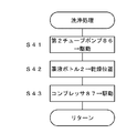
- the second tube pump 86 is driven to eject the cleaning water in the cleaning water tank 18 from the cleaning nozzle 83 ( Step S41). Thereby, the lower end portion of the first nozzle 51 is washed.
- the waste water after washing flows to the center of the bottom by the washing dish 80 and is collected from the waste water outlet 81 to the waste water tank through the waste water tube 82.
- the driving motor 32 is further driven to rotate the annular support 26 and move the chemical bottle 2 to the drying position (step S42). Then, the compressor 87 is driven to blow air to the first nozzle 51 via the air supply nozzle 84, and the attached cleaning water is dried (step S43).
- the space at the central portion surrounded by the attached chemical liquid bottle 2 that was originally a dead space is used for the stirring of the chemical liquid in the chemical liquid bottle 2. It can be used effectively as a moving area. For this reason, a chemical
- medical solution can be stirred, without enlarging an apparatus. Further, since the chemical liquid bottle itself is rotated, the chemical liquid can be sufficiently stirred. In addition, since the rotation drive unit 4 need only be provided at one place, the structure is not complicated and the cost is not increased.
- the present invention is not limited to the configuration described in the first embodiment, and various modifications can be made.
- the amount of the chemical liquid poured out from the chemical liquid bottle 2 into the patient bottle 6 is adjusted using a pinch valve, but the following configuration is also possible.
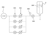
- two types of tube pumps one having a large delivery flow rate per unit time and one having a small delivery flow rate (may be three or more types having different delivery flow rates per unit time), are prepared.
- only one motor stepping motor, servo motor, etc.
- a tube pump having a large delivery flow rate is used until the set value before reaching the desired amount determined by the prescription data, and the set value is reached. For example, switch to a tube pump with a small delivery capacity.
- the dispensing process is performed by using a plurality of tube pumps without increasing the number of expensive motors, so that the dispensing error can be suppressed while realizing the optimum dispensing speed. .
- the cost is not increased so much.
- the tube 18a is opened and closed by the pressing member 92 that rotates about the support shaft 92a, and a fixed amount (for example, 5 ml) is used for the patient. You may make it supply a chemical
- the pressing member 92 is biased by a spring 93 so as to contact the outer periphery of the opening / closing cam 91.
- the tubes 18a, 52a and the like are used as they are.
- a coil spring is provided on the outer periphery, for example, the tubes 18a, 52a and the like are moved when the chemical bottle is rotated. It is preferable in that it can be prevented from being bent or stretched and its durability can be improved.
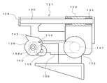
- FIG. 18 shows a dispensing device according to the second embodiment. Since this dispensing apparatus basically has the same configuration as that according to the first embodiment, the description of the same configuration is omitted, and the difference will be described below.
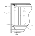
- the bottle support unit 101 includes a support base 102 and a guide member 103 fixed to the support base 102.
- the support base 102 includes a ceiling portion 104 and a pair of opposing side surface portions 105 extending downward from both side edge portions (a side surface portion located on the front side in FIG. 19 is not shown).
- a circular opening 106 is formed in the ceiling 104.
- a bottle mounting portion 107 is fixed to the upper surface of the ceiling portion 104.
- the bottle mounting portion 107 is made of an elastic material such as rubber, and includes a flat portion 108 screwed to the upper surface of the ceiling portion 104 of the support base 102 and a cylindrical portion 109 formed on the upper surface thereof.
- a first flow path connecting portion 110 and a second flow path connecting portion (not shown) are formed in the flat portion 108 in a region surrounded by the cylindrical portion 109, and the flat portion 108 communicates vertically. Yes.
- a female screw is formed on the inner peripheral surface of the cylindrical portion 109, and a male screw formed at the mouth of the chemical liquid bottle 2 can be screwed.
- One end of the tube 112 is connected to the lower end of the first flow path connecting part 110.
- the second flow path connecting portion is connected to the upper end portion of the first nozzle 51 extending into the chemical bottle 2 attached to the cylindrical portion 109, and to the lower end portion of the tube 52a.
- the bottle mounting portion 107 preferably has at least the second nozzle 52 integrated (the first nozzle 51 may be integrated) and is detachable from the support base 102.
- the bottle mounting part 107 integrated with the second nozzle 52 can be attached to the mouth of the chemical liquid bottle 2 in advance, the chemical liquid can be attached by mounting the chemical liquid bottle 2 as described above.
- the operation of inserting the second nozzle 52 into the inside of the bottle 2 becomes unnecessary, and the mounting operation to the bottle support portion 101 can be performed quickly and smoothly. Further, when the chemical bottle 2 is removed, there is no concern that the second nozzle 52 is exposed and the chemical liquid remaining in the second nozzle 52 leaks out.
- a pressure sensor (not shown) is provided in the middle of the air path from the first nozzle 51 to the pump 73 (for example, in the middle of the tube 52a), and the air pressure in the chemical liquid bottle 2 is detected.
- the pump 73 is driven and controlled based on the value detected by the pressure sensor so that the air pressure in the chemical liquid bottle 2 is maintained at a predetermined value. According to this, the air pressure in the chemical solution bottle 2 becomes too high, the amount of the chemical solution supplied to the patient bottle 6 increases per unit time, and the detection error by the weight detection sensor 65 does not occur. Further, by increasing the air pressure according to the viscosity of the chemical liquid stored in the chemical liquid bottle 2, there is no possibility of defective discharge.
- the pressure detected by the pressure sensor does not increase even though the rotational speed of the pump 73 is increased.
- the adjustment of the air pressure in the chemical liquid bottle 2 based on the value detected by the pressure sensor may be changed according to the chemical liquid amount.
- the amount of the chemical solution in the chemical solution bottle 2 is calculated based on the detected amount of the chemical solution based on the detection value of the weight detection sensor 65, or the discharged chemical solution is directly detected by the flow sensor, and the obtained discharge amount Is obtained by subtracting from the initial amount of the chemical solution in the chemical solution bottle 2. According to this, the remaining amount of the chemical liquid in the chemical liquid bottle 2 is reduced, and it is not difficult to discharge the chemical liquid due to its own weight, and quick dispensing can be performed to the end.
- a rotating piece 113 is supported on the other side surface portion (side surface portion opposite to the side surface portion 105 to which the guide member 103 is fixed) of the support base 102. It is attached so as to be rotatable around 113a.
- the rotating piece 113 has a substantially fan shape, and a linear portion extending in the radial direction from the support shaft side is bent in a direction orthogonal to form a contact portion.
- the guide member 103 has an arcuate guide groove 114 formed from the upper end to the lower end at the center of the side surface. Guide pieces 115a and 115b project from both ends of the guide groove 114, respectively. A tube 112 described later is disposed in the guide groove 114. A through hole 103 a through which the tube 112 is inserted is formed on the lower side of the guide member 103. A first pressing member 117 is attached to the vicinity of the through hole 103a so as to be rotatable about a support shaft 117a. Further, the guide member 103 is fixed with a support guide 116 for guiding a support shaft 138a which is a rotation center of a cam member 139 and a second pressing member 145, which will be described later.
- the first pressing member 117 includes a thin upper portion 118, a thick intermediate portion 119, and a lower portion 120 that extends from one side of the intermediate portion 119 and is provided with a support shaft 117a.
- first protrusions 121 and second protrusions 122 are formed at two positions in the width direction, respectively.
- a rotation piece 113 (described later) and a protrusion 143 of the cam member 139 are in contact with and pressed against the protrusions 121 and 122, respectively.
- a concave portion 123 that is recessed from the upper portion 118 and the lower portion 120 is formed at the side edge portion of the intermediate portion 119.
- the recess 123 is formed with a first pressing portion 124 that protrudes in the same direction as the support shaft 117a.
- the first pressing part 124 plays a role of pressing the tube 112 and closing the flow path, or separating and opening the tube 112.
- a locking hole 125 is formed in the intermediate portion 119, and a coil spring 126 is locked between the locking hole 125 and a locking shaft 103 b fixed to the guide member 103. Accordingly, the first pressing member 117 is urged counterclockwise in FIG. 19 around the support shaft 117a, and is positioned at the closed position where the first pressing portion 124 closes the flow path of the tube 112. .
- an operation unit 127 is attached to the apparatus main body 1.
- the operation unit 127 is provided at the pouring position of the apparatus main body 1 and includes a mounting frame 128 and a sliding member 129 slidably supported on the mounting frame 128 as shown in FIG. is there.
- the mounting frame 128 has a rectangular frame shape, and two sliding rails 130 are juxtaposed between a pair of opposing side walls.
- the sliding motor 131 is attached to the outer surface of one of the other set of side walls of the mounting frame 128, and the rotation motor 132 is attached to the outer surface of the other side wall.
- the sliding member 129 is slidably attached to the sliding rail 130 via the bush 133. Then, when the sliding motor 131 is driven to rotate forward and backward, the sliding member 129 is moved forward and backward through the pinion 131a and the rack 131b provided on the rotating shaft, respectively. Positioning is possible.
- the operating position and the standby position are specified by detecting a part of the detected plate 134 attached to the upper surface of the sliding member 129 by the first sensor 135 and the second sensor 136 provided on the side surface of the attachment frame 128, respectively.
- the positioning can be performed by driving and stopping the sliding motor 131. As shown in FIG.
- the sliding member 129 includes a top plate and side plates extending downward from both side edge portions thereof, and a mounting plate 138 extending further forward is fixed to the side plate.
- a cam member 139 and a second pressing member 145 are integrally attached to the attachment plate 138 so as to be rotatable about a support shaft 138a.
- the cam member 139 is made of a metal plate, and is supported on the mounting plate 138 so as to be rotatable forward and backward about the support shaft 138a.
- a first pulley 140 is provided on the support shaft 138 a, and power is transmitted by a belt 142 that extends between the first pulley 140 and a second pulley 141 that is rotationally driven by a rotation motor 132.
- On the outer peripheral edge of the cam member 139 an extended region is formed that bulges in the outer diameter direction within a predetermined angle range from the support shaft 138a that is the rotation center. In FIG. 19, a part of the extended region on the counterclockwise direction side is a protruding portion 143 that further protrudes.
- the protrusion 143 presses the second protrusion 122 of the first pressing member 117 when the cam member 139 rotates counterclockwise about the support shaft 138a, and the first pressing member 117 is centered on the support shaft 117a. And rotate clockwise.
- a pressing roller 144 is attached to a part of the extended region on the clockwise direction side. The pushing roller 144 pushes and turns the turning piece 113 when the cam member 139 is turned clockwise about the support shaft 138a. Thereby, the rotating piece 113 presses the first protrusion 121 of the first pressing member 117, and the first pressing member 117 is rotated clockwise about the support shaft 117a.
- the second pressing member 145 has a configuration in which a pressing roller 147 is rotatably attached to a support piece 146 fixed to the cam member 139 as shown in FIG.
- the thickness of the pressing roller 147 is set to be slightly smaller than the width dimension of the guide groove 114 of the guide member 103.
- the pressing roller 147 is also rotated around the support shaft 138a together with the cam member 139.
- the support shaft 138 a is guided by a support shaft guide 116 fixed to the guide member 103. Therefore, the rotation trajectory of the pressing roller 147 can be set to a position along the guide groove 114 with high accuracy. Then, while the pressing roller 147 moves through the guide groove 114, the tube 112 disposed therein is pressed to maintain the flow path in a closed state.
- a fall prevention member 148 supported by a plurality of support bars (not shown) protruding downward is attached to the ceiling surface of the apparatus body 1.
- This overturn prevention member 148 is formed by cutting out a part of the annular body into a substantially C shape, and reliably prevents the chemical solution bottle 2 arranged in an annular shape from accidentally falling over. Further, the notch portion is located just at the rotation position, and the rotation of the chemical liquid bottle 2 is allowed.
- magnets are provided at two positions on the side surface of the driven gear portion 49, and the rotation range of the chemical liquid bottle 2 is regulated by detecting the position of each magnet with a sensor (not shown). It is preferable to do this.
- the inside of the fall prevention member 148 is rotated through the notch, and beyond the position directed vertically downward to the attaching / detaching position directed obliquely downward on the front side of the apparatus (about It can be rotated (within a range of 200 °). Since the chemical solution bottle 2 can be attached and detached while being directed obliquely downward at the attachment / detachment position, the workability is excellent.
- the rotation of the chemical liquid bottle 2 is performed by detecting a magnet provided in the driven gear portion 49, there is no electrical component provided on the annular support 26 to which the chemical liquid bottle 2 is mounted. Therefore, the electric wire for power supply to the annular support 26 side is not required, and the rotation range of the annular support 26 is limited to the range of one rotation each in the forward and reverse directions as in the configuration of the first embodiment. There is no. That is, the restriction on the rotation range of the annular support 26 can be eliminated.
- the rotation of the annular support 26 may be managed based on detection signals from the encoder 33 and the origin sensor.
- the operation of the dispensing apparatus according to the second embodiment is substantially the same as that according to the first embodiment, but the stirring process when stirring the chemical liquid stored in the chemical liquid bottle 2, and the chemical liquid bottle 2 To the patient bottle 6 is different from the dispensing process.
- the chemical solution bottle 2 can sufficiently agitate the chemical solution and minimize the rotation range to shorten the agitation time.
- the liquid surface position is the center position of the bottom surface.
- An inclination angle exceeding (the vertical center position when the chemical liquid bottle 2 is set to the horizontal position) is calculated.
- medical solution bottle 2 is rock
- medical solution bottle 2 can be fully stirred. Further, the swing range does not become larger than necessary, and the stirring time can be shortened.
- the rotation angle is set before the chemical solution amount becomes less than half.
- a minimum fixed value may be used.
- the rotation range can be determined not only by the liquid level position of the chemical liquid on the bottom surface of the chemical liquid bottle 2, but also by the liquid level position on the side surface of the chemical liquid bottle 2. Further, by experiment, the amount of the chemical solution stored in each chemical solution bottle 2 may be changed to determine the minimum turning range in which it is determined that the chemical solution can be sufficiently stirred.
- the sliding motor 131 is driven to advance the sliding member 129 (step S51). Then, based on the detection signal from the first sensor 135 (step S52), the driving of the sliding motor 131 is stopped (step S53), thereby positioning the sliding member 129 at the operating position. At this time, the support shaft 138 a provided on the mounting plate 138 of the sliding member 129 is guided by the support shaft guide 116, and the cam member 139 and the second pressing member 145 are accurately positioned with respect to the guide member 103.
- the cam member 139 is rotated in the clockwise direction in FIG. 19 by forwardly driving the rotation motor 132 (step S54). Accordingly, the pushing roller 144 provided on the cam member 139 presses the rotating piece 113, and the rotating piece 113 rotates counterclockwise about the support shaft 113a. The rotating piece 113 presses the first protrusion 121 of the first pressing member 117, and the first pressing member 117 rotates clockwise about the support shaft 117a. As a result, the first pressing portion 124 of the first pressing member 117 is separated from the tube 112, and the chemical solution in the chemical solution bottle 2 flows out to the patient bottle 6.
- the supply of the chemical solution to the patient bottle 6 is performed until a predetermined dispensing amount (for example, a value 20 ml smaller than the dispensing amount) immediately before the dispensing amount obtained from the prescription data is reached.
- a predetermined dispensing amount for example, a value 20 ml smaller than the dispensing amount
- the dispensing is continued until the weight of the drug solution in the patient bottle 6 obtained by subtracting the weight of the patient bottle 6 from the weight detected by the weight detection sensor 65 reaches the predetermined dispensing amount.
- the dispensing may be continued until the time when the predetermined dispensing amount is expected to be reached (the maximum dispensing process is described above). ).
- the rotation motor 132 is driven in reverse (step S56), and the cam member 139 and the first pressing member 117 are rotated counterclockwise. Accordingly, the first pressing member 117 is released from the pressing force received from the pressing roller 144 provided on the cam member 139 via the rotating piece 113, and returns to the closed position by the biasing force of the coil spring 126.
- the pressing roller 147 of the cam member 139 reaches the guide groove 114 formed in the guide member 103 as shown in FIG. 20, and presses the tube 112 to close the flow path.
- medical solution will be temporarily stored in the restriction
- the amount of the chemical stored in this restricted area is 5 ml.
- the protrusion 143 of the cam member 139 presses the second protrusion 122 of the first pressing member 117, and the first pressing member 117 rotates from the closed position to the open position.
- region is discharged
- the pressing roller 147 moves in the guide groove 114, and the tube 112 is maintained in the closed state.
- the pressing roller 147 moves away from the guide groove 114, the pressing state by the protruding portion 143 of the cam member 139 is released, and the first pressing member 117 returns to the original closed position.
- the rotation of the cam member 139 is continued to temporarily store the chemical solution in the restriction region, and sequentially supply a certain amount of the stored chemical solution to the patient bottle 6 (above, Small volume dispensing process).
- the weight is detected by the weight detection sensor 65 in the bottle mounting portion 60 on which the patient bottle 6 is mounted (step S57). Then, based on the weight of the chemical solution in the patient bottle 6 obtained by subtracting the weight of the patient bottle 6, the cam member 139 is obtained until a desired dispensing amount based on the prescription data is obtained (step S ⁇ b> 58). Then, the chemical solution is supplied into the patient bottle 6 by a certain amount.
- step S58 YES
- step S59 the rotation motor 132 is stopped (step S59) and the sliding motor 131 is driven in reverse (step S59).
- step S61 Based on the detection signal from the second sensor 136 (step S61), the sliding motor 13 is stopped (step S62), and the sliding member 129 is moved to the standby position.
- the tube 112 is fully opened and dispensed at a high speed until just before the desired dispensing amount is reached, and thereafter, a certain small amount is dispensed.
- the supply amount of the chemical solution into the final patient bottle 6 can be made stepwise by small amounts, and measurement errors due to the weight detection sensor 65 can be suppressed.
- the configuration can be simplified and manufactured at low cost.
- the dispensing amount is not limited to this, and can be freely changed according to the type of chemical solution, dispensing accuracy, and the like. Can do. In this case, what is necessary is just to adjust the chemical
- the stored chemical liquid is agitated by rotating the chemical liquid bottle 2, but the entire dispensing apparatus is vibrated or the forward / reverse rotation of the annular support 26 is performed in small increments. You may make it carry out by repeating.
- the supply of the chemical solution into the patient bottle 6 may be performed by a user operating a not-shown operation button so that a certain amount is supplied or continuously.
- the second pressing member 145 is driven to rotate in the forward and reverse directions.
- the following configuration is also possible only by driving in the forward direction.
- the chemical solution stored in the tube 112 is dispensed by the pressing roller 147 and the first pressing portion 124 of the first pressing member 117.
- the tube is repeatedly pressed and released by the first pressing member 117 and the second pressing member 145, and the chemical solution is dispensed by a certain amount.
- the second pressing member 145 is separated from the tube 112 via the mounting plate 138.
- the second protrusion 122 is pressed by the protruding portion 143 of the cam member 139 that moves together with the second pressing member 145 to rotate the first pressing member 117. It is necessary to release the pressing state by the first pressing portion 124.
- the flow path of the tube 112 is fully opened, and the chemical solution is continuously dispensed.
- the components used at the time of reverse rotation such as the 1st protrusion 121 and the rotation piece 113, become unnecessary.
- the small-quantity dispensing process and the maximum dispensing process are performed by the first pressing member and the second pressing member.
- the following configuration is also possible. .
- FIG. 26 illustrates a pressing member in which the pressing rollers 151 and 152 are rotatably provided at two positions (a 180-degree symmetrical position) on the outer periphery of the support disc 150.
- the tube 112 is pressed by the pressing rollers 151 and 152, and the support disc 150 is rotated.
- the chemical solution stored between the pressing rollers 151 and 152 is moved downwardly from the tube 112 by the pressing roller 151 positioned on the lower side, and the pressing roller 152 positioned on the upper side moves to the tube 112. It is discharged by making a circular motion while maintaining the pressed state along.
- the circular motions of the pressure rollers 151 and 152 are continued, and the chemicals stored between the pressure rollers 151 and 152 are sequentially discharged.
- the pressure rollers 151 and 152 are separated from the tube 112 via the mounting plate 138, and the flow path is fully opened.
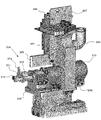
- FIG. 27 shows a dispensing device according to the third embodiment. Since this dispensing apparatus basically has the same configuration as that according to the first embodiment, the description of the same configuration is omitted, and the difference will be described below.
- the apparatus main body 161 has a detachable space 163 for allowing the chemical solution bottle 2 to be attached and detached, and a patient bottle 6 on the lower side of the display 162, and dispensing for dispensing the chemical solution in the chemical solution bottle 2.
- the detachable space 163 can be opened and closed by a shutter 165 provided so as to be slidable in the horizontal direction along the front and right sides of the apparatus main body 161.
- the shutter 165 can open not only the front side but also the side area. Therefore, the attaching / detaching operation of the chemical liquid bottle 2, the internal cleaning, the maintenance, and the like can be easily performed.
- a bottle support 166 is provided as shown in FIG.
- the bottle support portion 166 has a configuration in which a plurality of rotation support portions 168 are provided on an annular support body 167 provided in the apparatus main body 161.
- a mechanism for rotating the chemical liquid bottle 2 supported by the rotation support unit 168 (a rotation driving unit 185 described later) and a mechanism for discharging the chemical liquid from the chemical liquid bottle 2 to the patient bottle 6 (described later).
- the moving member 253, the second pressing member 254, etc.) are disposed in the vicinity of the annular support 167, and a wide space can be secured on the lower side. For this reason, it is possible to make the above-mentioned attachment / detachment space 163 and dispensing space 164 sufficiently wide.
- annular support 167 Although the details of the annular support 167 are not shown, an annular guide portion protruding in a substantially triangular cross section is formed on the outer peripheral portion.
- the annular support 167 is supported at four locations of the annular guide portion by a support roller having a substantially V-shaped groove formed on the outer peripheral surface thereof, and can be rotated by driving a motor.
- the annular support 167 is provided with rotation support portions 168 at equal intervals in a plurality of locations in the circumferential direction, and the chemical bottle 2 is supported on each rotation support portion 168 (in FIG. 28, the rotation support portion 168). And only two of the chemical bottles 2 are shown).
- the rotation support unit 168 includes a support base 169 and a rotation part 171 that is connected to the support base 169 so as to be rotatable about a support shaft 170.
- the support base 169 includes a support main body 172 having a bifurcated lower end side, and a groove 173 in the support main body 172 (when attached to the annular support 167, the outer diameter of the annular support 167 Side wall part 174 formed on the side) and an attachment part 175 extending from the upper end of the support body 172.
- a through-hole 172a (the side wall portion side is not shown) is formed in the support main body 172 and the side wall portion 174, and a support shaft 170 is inserted therethrough as shown in FIG.
- a driven gear 176 in which a region where a gear is formed is limited by cutting a part of the outer peripheral surface is fixed to one end portion of the support shaft 170.
- a circular opening (not shown) is formed in the side wall part 174, and a rod 208 of a lock mechanism 186 described later can be projected and retracted in the groove part 173 through the opening.
- the rotating portion 171 is obtained by fixing a pair of arm portions 179 a and 179 b via a spacer 178 to a rotating plate 177 that is provided on the support base 169 so as to be rotatable about a support shaft 170.
- Rotating plate 177 has a configuration in which both side walls 181a and 181b are arranged opposite to each other on both sides of intermediate wall 180 and one end thereof is covered with ceiling wall 182. The other end portions of the side walls 181a and 181b further extend from the intermediate wall 180, and the extended portion is rotatably supported by a support shaft 170 provided on the support base 169.
- One side wall 181a is formed with an opening (not shown) through which a rod 208 of a lock mechanism 186 described later is inserted.
- a substantially U-shaped guide portion 183 is formed by the spacer 178 and the both arm portions 179a and 179b, and the stopper 219 attached to the chemical liquid bottle 2 is detachable.
- One arm portion 179b is formed with a rectangular locking hole 184, and a locking claw 233 provided on the plug 219 can be engaged and disengaged. Accordingly, the chemical liquid bottle 2 can be held by the both arm portions 179a and 179b via the plug body 219, that is, the plug body member 218.
- the chemical solution bottle 2 can be held by the arm portion 179 protruding from the rotation plate 177 of the rotation support portion 168 to the inside of the annular support body 167. Therefore, when the rotation support part 168 is rotated, the chemical bottle 2 moves from the attachment / detachment preparation position on the upper inner side of the annular support 167 to the attachment / detachment position in the attachment / detachment space 163 on the lower outer side. That is, the attachment / detachment position can be set to a position where it is easy to work from the outside of the apparatus main body 161.
- the liquid chemical bottles 2 supported by the respective rotation support portions 168 by the rotation of the annular support 167 are transported by a predetermined pitch in the circumferential direction, and the transport positions include an attaching / detaching preparation position of the chemical liquid bottle 2 and a dispensing position. It is.
- a rotation drive unit 185 and a lock mechanism 186 are arranged.
- the rotation drive unit 185 includes a rotation drive main body 187, a first motor unit 188 that can be moved up and down on the rotation drive main body 187, and the first motor unit 188. And a second motor unit 189 that moves up and down, and is positioned below the rotation support unit 168.
- the rotation drive main body 187 includes a bottom plate 190 having a rectangular shape in plan view, and guide frames 191 provided at both ends thereof. A region surrounded by the guide frame 191 and the bottom plate 190 is provided with a pair of guide shafts 192 (one not shown) at a predetermined interval in the width direction. And the raising / lowering block 193 is each provided so that raising / lowering along the guide shaft 192 is possible.
- the first motor unit 188 includes a cover body 197 including a front plate 194, both side plates 195, and a top plate 196.
- the first motor 198 is fixed to the back of the front plate 194, and the first motor 188 is disposed on the front of the front plate 194.
- a drive gear 199 and an intermediate gear 200 are provided.
- the first drive gear 199 is attached to the rotation shaft of the first motor 198 that passes through the front plate 194 and protrudes to the front side. Further, the intermediate gear 200 is rotatable around the shaft portion and meshes with the first drive gear 199. Accordingly, when the first motor 198 is driven to rotate in the forward and reverse directions, the intermediate gear 200 rotates in the forward and reverse directions via the first drive gear 199.
- the second motor unit 189 meshes with the second motor 201 fixed to the bottom plate 190 of the rotation drive main body 187 and the second drive gear 202 provided on the rotation shaft of the second motor 201, and the one lifting block 193 is engaged. And a rack portion 203 fixed to the rack.
- the lifting block 193 moves up and down along the guide shaft 192 from the second driving gear 202 via the rack portion 203.
- the elevating block 193 is moved upward, the intermediate gear 200 is raised accordingly, and the intermediate gear 200 meshes with the driven gear 176 of the support base 169.
- the lock mechanism 186 is for restricting the position of the rotating portion 171 with respect to the support base 169, as shown in FIGS.
- the lock mechanism 186 positions the rotating portion 171 with respect to the support base 169 and maintains the chemical bottle 2 in an upside down state, and an operation member for operating the lock member 204. 205.
- the lock member 204 is attached to each rotation support portion 168, and the operation member 205 is disposed in the vicinity of the attachment / detachment preparation position.
- the lock member 204 includes a lock main body 206 that is screwed and fixed to the side wall 174 of the support base 169, and a rod portion 207 that is slidably held by the lock main body 206.
- the lock body 206 is formed in a rectangular frame shape.
- the rod portion 207 is obtained by connecting a pair of upper and lower rods 208 with two right and left connecting rods (a first connecting rod 209a close to the support base 169 and a second connecting rod 209b far away). Each rod 208 is slidably disposed on an upper part and a lower part of the lock body 206.
- the connecting rod 209 is disposed in the opening portion so as to be movable in the left-right direction through the elongated holes in the upper portion and the lower portion that open to the opening portion 206a of the lock body 206.
- the actuating member 205 includes an actuating body 210, an actuating bar 211 that can be moved in and out of the actuating body 210, and an actuating motor 212 for reciprocating the actuating bar 211.
- the operation main body 210 has a thin, substantially rectangular parallelepiped shape, and a communication hole communicating with the upper and lower surfaces is formed at a position slightly shifted from the center to one side edge.
- a communication hole communicating with the upper and lower surfaces is formed at a position slightly shifted from the center to one side edge.
- an opening that also opens at a part of the inner peripheral surface constituting the communication hole is formed on the upper surface of the operation main body 210.
- elongated holes are respectively formed at three locations along the side edge portion.
- Three magnetic sensors 213 are attached to each slot.
- the actuating bar 211 is rod-shaped, and on one end side, a substantially triangular first protrusion 214 and a second protrusion 215 are formed on the left and right sides at two positions in the longitudinal direction.
- a permanent magnet (not shown) is provided on the upper surface of the other end side of the operation bar 211. The permanent magnet is detected by each magnetic sensor 213 so that it can be determined whether the operation bar 211 is located at the reference position, the first protruding position, or the second protruding position.
- the actuating bar 211 is in the first projecting position, and the first projecting portion 214 presses the first connecting rod 209a, and the rod 208 projects to the support base 169 side to the opening formed in the side wall 181a of the rotating plate 177.
- Positioning restricts the position of the rotation plate 177 (the rotation part 171) with respect to the support base 169 (locked state). Further, the operating bar 211 is the second projecting position, the second projecting portion 215 presses the second connecting rod 209b, and the rod 208 is retracted from the support base 169 side to make the pivot plate 177 pivotable ( Unlocked).
- a rack gear (not shown) is formed on one side surface of the operation bar 211.
- the driving motor 212 has a drive gear 216 integrated with a rotating shaft, and is fixed to the operating body 210 via a mounting plate 217. In this fixed state, the drive gear 216 is positioned in the communication hole of the operation main body 210 and functions as a pinion that meshes with the rack gear of the operation bar 211 through the opening.
- the operating motor 212 is driven to rotate forward and backward in accordance with a control signal from the control device based on the detection signal from each magnetic sensor 213.
- a plug member 218 is attached to the upper opening of the chemical liquid bottle 2. 36 to 38, the plug body member 218 is a flexible material connected to one of a plug body 219 and a pair of through holes (not shown) penetrating the plug body 219.
- the first tube 221 functions as the chemical liquid dispensing nozzle of the present invention.
- the stopper 219 has a substantially rectangular parallelepiped shape, and a concave portion 224 having a circular shape in a plan view in which the mouth portion of the chemical liquid bottle 2 can be arranged is formed on the mounting surface.
- a female screw (not shown) is formed on the inner peripheral surface of the recess 224, and a male screw formed at the mouth of the medicine bottle 2 can be screwed together.
- a pair of through holes are formed in the bottom surface of the recess 224.
- An air nozzle 220 is connected to one of the through holes, and air is supplied into the chemical liquid bottle 2 through the air nozzle 220.
- the other through-hole is for discharging the chemical solution from the chemical solution bottle 2 and is connected to the first tube 221.
- an RFID 225 (Radio Frequency ⁇ ⁇ IDentification) is built in the mounting surface in the vicinity of the recess 224.
- the RFID 225 stores a specific ID (IDentification: hereinafter referred to as an attachment position ID) for identifying which rotation support unit 168 is the rotation support unit 168.
- the mounting position ID stored in the RFID 225 is written by an RFID reader / writer (not shown).
- a protrusion 226 is formed on the upper end of the side surface of the stopper 219, and a bottle stopper 227 is slidably attached thereto.
- the bottle fastener 227 is formed by molding a synthetic resin material into a substantially U shape, and includes a side wall portion 228 that surrounds the three surrounding sides and a U-shaped presser portion 229 that bulges inward from the inner edge portion. Yes.
- a groove 230 is formed at the lower end of the facing surface of the side wall 228, and the protrusion 226 of the plug 219 is located.
- the holding portion 229 is engaged with the annular bulging portion 2a of the chemical liquid bottle 2 simply by sliding the bottle stopper 227. Stop.
- the chemical bottle 2 is not screwed to the concave portion 224 of the stopper 219 to an appropriate position, the bottle fastener 227 cannot be properly locked to the annular bulging portion 2a of the chemical bottle 2, and the screw bottle 2 is screwed. It is understood that the state is insufficient.
- a latch member 231 is provided in the plug body 219.
- the latch member 231 immerses the locking claw 233 protruding from one side surface by pressing the pressing portion 232 protruding from one end side.
- the pushing portion 232 of the latch member 231 protrudes from one end surface of the plug body 219 so as to be pushed in, and the locking claw 233 protrudes from one side surface of the plug body 219 so as to be retractable.
- the locking claw 233 is engaged with and disengaged from a locking hole 184 formed in one arm portion 179 b of the rotating portion 171 so that the plug 219 can be attached to the rotating portion 171 of the rotating support portion 168.
- a communication hole (not shown) is opened on the bottom surface of the plug 219.
- the first tube connector 234 is connected to one through hole, and one end of the first tube 221 is connected to the first tube connector 234.
- a second tube connector 235 is connected to the other through hole, and an opening on one end side of the second tube 236 is further connected thereto.
- a third tube connector 237 is connected to the communication hole, and the other end side opening of the second tube 236 is connected to the communication hole.
- the communication hole extends to one end surface of the plug 219, and a conical guide recess 238 is formed at the opening position.
- a pressure receiving piece 239 attached so as to be rotatable about the shaft portion 239a is provided.
- One end portion of the pressure receiving piece 239 protrudes obliquely from the plug body 219 to the side, and the other end portion presses the second tube 236 against the substantially U-shaped guide receiving portion 240 fixed to the bottom surface of the plug body 219. Yes.
- the pressure receiving piece 239 rotates when a pressing plate 269 (described later) is pressed against one end of the pressure receiving piece 239 to release the closed state of the second tube 236 and open the flow path.
- the air nozzle 220 is connected to one through hole formed in the concave portion 224 of the stopper 219 and extends into the chemical liquid bottle 2, and its tip is located near the bottom surface of the chemical liquid bottle 2.
- the guide member 222 is provided with a first guide portion 241 and a second guide portion 242 on a support plate 222 a fixed to the bottom surface of the plug 219.
- the first guide portion 241 is fixed to one side surface of the support plate 222a, and has a curved surface 243 that gradually protrudes forward as the end surface on the protruding side moves downward.
- the front end portion of the curved surface 243 is cut away leaving both side portions to form a groove-shaped portion 244, and the bottom surface thereof is constituted by a flat pressure receiving surface 245.
- the first guide part 241 includes a first link plate 246, a second link plate 247, and a first pressing member 223 attached to the other side surface of the support plate 167.
- the first link plate 246 is attached to the support plate 222a so as to be rotatable about the support shaft 246a.
- the first link plate 246 has a press receiving portion 248 formed by extending one end portion thereof in a right angle direction.
- a pressing roller 273 integrated with the cam 271 is pressed against the pressing receiving portion 248, and the first link plate 246 rotates.
- the second link plate 247 is attached to the support plate 222a so as to be rotatable about the support shaft 247a.
- a first pressure receiving roller 249a is rotatably provided on one surface of the second link plate 247, and a second pressure receiving roller 249b is rotatably provided on the other surface.
- the second link plate 247 is biased by a spring 250 (not locked in FIG. 36), and the second pressure receiving roller 249b is pressed by a pressing portion 274 formed on the cam 271 of the second pressing member 254. As a result, it rotates counterclockwise in FIG. 36 about the support shaft 247a against the urging force of the spring 250.
- the first pressing member 223 is fixed to the second link plate 247.
- the first pressing member 223 includes a pressing protrusion 251 whose one end bulges in a semicircular cross section.
- the pressing protrusion 251 of the first pressing member 223 enters the groove-shaped portion 244 of the first guide portion 241.
- the pressing protrusion 251 approaches the pressing receiving surface 245, the first tube 221 disposed there is crushed and elastically deformed, and the flow path is closed.
- the second link plate 247 rotates when the first pressing receiving roller 249a is pressed by the pressing portion 274 formed on the cam 271 of the second pressing member 254, and the second link plate 247 is rotated by the pressing protrusion 251.
- the pressed state of the first tube 221 is released to open the flow path.
- the second guide part 242 is fixed to the support plate 222a, and a through hole (not sushi) is formed on the free end side.
- a fourth tube connector 252 is connected to the through hole, and the first tube 221 is connected to the fourth tube connector 252.
- the second pressing member 254 for adjusting the outflow amount of the chemical liquid that is moved by the moving member 253 and poured out from the chemical liquid bottle 2 can be disposed at the extraction position.
- the moving member 253 includes a slide base 256 that can be moved forward and backward by driving a slide motor 255.
- a rack 257 is formed on the side of the slide table 256, and a pinion (not shown) provided on the rotation shaft of the slide motor 255 is engaged with the rack 257.
- the movement of the slide base 256 is detected by the slide position detection sensor 258, and the second pressing member 254 can be positioned at the forward position and the backward position, respectively.
- a holding block 259 for holding the slide motor 255 is provided above the slide table 256.
- an air supply pipe 260 and a nozzle portion 261 connected thereto are provided on the upper side of the holding block 259.
- the air supply pipe 260 is connected to an air supply source 262 and ejects air supplied therefrom from the nozzle portion 261.
- the nozzle portion 261 is inserted into a guide recess 238 formed on the end surface of the plug 219 and connected to a communication hole (not shown). Therefore, the ejected air is supplied from the air nozzle 220 into the chemical liquid bottle 2 through the communication hole.
- a compressor is used for the air supply source 262, and in the middle of the path to the nozzle portion 261, four sets of a switch valve 263 and a needle valve 264 connected in series from the air supply source side are connected in parallel, and beyond that An open / close valve 265 and a pressure sensor 266 are connected. Any one of the four switch valves 263 is opened, and air can flow only in one flow path.
- the needle valve 264 has different flow rates per unit time that can be passed. Then, by opening any one of the switch valves 263, the amount of air supplied into the chemical liquid bottle 2 can be adjusted.
- the opening / closing valve 265 and the pressure sensor 266 are not necessarily required.
- the substrate 268 and the pressing plate 269 are fixed to the holding block 259 via the holding plate 267.
- the pressing plate 269 presses and rotates one end of the pressing receiving piece 239 when the slide base 256 is advanced. And when the press receiving piece 239 rotates, the 2nd tube 236 arrange
- the second pressing member 254 is attached above the slide base 256.
- the second pressing member 254 includes a cam 271 provided on the rotation shaft of the rotation motor 270.
- a pressing protrusion 272 is formed on one surface of the cam 271. Then, when the rotation motor 270 is driven to rotate in the forward direction to rotate the cam 271 in the forward direction, the pressing protrusion 272 comes into contact with the lower edge 261a of the first link plate 246, and the first link plate 246 is moved (in FIG. 36, Rotate clockwise about the spindle 246a.
- a rotatable pressing roller 273 is provided on the other surface of the cam 271. Then, when the rotating motor 270 is driven in reverse to reversely rotate the cam 271, the pressing roller 273 comes into pressure contact with the first tube 221. Then, by rolling while changing the pressure contact position, the chemical solution in the first tube 221 is sent out by a predetermined amount. At this time, the pressing protrusion 272 contacts the upper edge 261b of the first link plate 246 and rotates the first link plate 246 (in the counterclockwise direction around the support shaft 246a in FIG. 36). The first link plate 246 has no influence on other members.
- a pressing portion 274 that protrudes partially is formed on the outer peripheral portion of the cam 271.
- the pressing portion 274 is in pressure contact with the second pressing receiving roller 249 b of the second link plate 247 and rotates the second link plate 247. Then, by rotating the first pressing member 223 integrated with the second link plate 247, the pressing of the first tube 221 by the pressing protrusion 251 is temporarily released.
- the cam 271 provided on the second pressing member 254, the link plates 246, 247, etc. function as interlocking members according to the present invention, and operate in conjunction with the first pressing member 223 and the second pressing member 254. It can be made to.
- the first pressing member 223, the second pressing member 254, and the like constitute a chemical solution discharging mechanism.
- the plug member 218 is attached to the mouth of the chemical liquid bottle 2. That is, the air nozzle 220 is inserted from the mouth portion of the chemical liquid bottle 2 and covered with the plug body 219, and the mouth portion is disposed in the recess 224 of the plug body 219. Then, the bottle stopper 227 is slid, and the stopper member 218 is fixed to the chemical liquid bottle 2 by the pressing portion 229. As described above, the plug member 218 can be easily attached to the chemical liquid bottle 2 simply by inserting the air nozzle 220 into the chemical liquid bottle 2, covering the mouth portion with the stopper 219, and sliding the bottle stopper 227. be able to.
- the barcode attached to the outer peripheral surface of the chemical bottle 2 is read with a barcode reader.
- the data stored in the storage unit 89 is referred to, and information related to the corresponding drug (name of drug, code number, etc .; hereinafter referred to as drug solution information) is called and written in the RFID 225.
- the shutter 165 is slid to expose the attachment / detachment space 163.
- the shutter 165 it is possible to secure a wide area that opens not only on the front side of the apparatus main body 161 but also on the side side, and that allows easy access to the attachment / detachment space 163.
- This is only when the chemical bottle 2 supported by the rotation support portion 168, the lock mechanism 186, the moving member 253, the second pressing member 254, etc. are arranged above the annular support 167 and the chemical bottle 2 is replaced.
- the rotation support portion 168 is rotated to move the chemical liquid bottle 2 to the attachment / detachment space 163 below the annular support 167. Therefore, in addition to the attaching / detaching operation of the chemical liquid bottle 2 described below, cleaning of the attaching / detaching space 163, other maintenance, and the like can be performed smoothly.
- medical solution bottle 2 is each mounted
- the lock member 204 is operated to bring the rotating portion 171 into the unlocked state, and then the rotating drive portion 185 is moved (the second motor portion 189 is driven to move the first motor portion 188).
- the intermediate gear 200 of the rotation drive unit 185 is engaged with the driven gear 176 of the rotation support unit 168.
- the first drive gear 199 is rotated and the driven gear 176 is rotated via the intermediate gear 200.
- the rotation part 171 of the rotation support part 168 rotates from the attachment / detachment preparation position to the attachment / detachment position.
- the storage unit 89 stores the chemical information stored in the chemical bottle 2 to be attached and the attachment position ID of the rotation support unit 168 of the rotation unit 171 located at the attachment / detachment position.
- the data table of the storage unit 89 is inquired, and the chemical solution bottle 2 in which the corresponding chemical solution is stored is specified from the associated mounting position ID. And the corresponding chemical
- position information that associates the rotation position with the positional relationship of the chemical liquid bottle 2 supported by each rotation support portion 168 is stored, and the annular support 167 is rotated based on the position information. What should I do? Further, an RFID reader / writer may be provided at the extraction position and the RFID 225 may be read to identify the position of the rotation support 167.
- the bottle placing portion 60 on which the patient bottle 6 is placed is raised, and the upper opening thereof is positioned in the vicinity of the fourth tube connector 252. Further, by driving the slide motor 255, the slide base 256 is advanced, and the second pressing member 254 is positioned at a predetermined position with respect to the rotation support portion 168. At this time, the rotation shaft of the rotation motor 270 provided on the second pressing member side is positioned in the positioning recess 224 formed in the spacer 178 on the rotation support portion side. Further, the air nozzle 220 enters the guide recess 238 of the plug 219 and is connected to the communication hole 234. Further, the pressing plate 269 presses the pressure receiving piece 239 and rotates it to release the second tube 236 from the crushed state.
- the rotation motor 270 is driven to rotate in the reverse direction, the cam 271 is rotated in the reverse direction, and the pressure receiving portion 248 is pressed by the pressing roller 273, thereby rotating the first link plate 246.
- the pressure receiving roller 249 is pressed by the lower edge of the first link plate 246 to rotate the second link plate 247, and the first pressing member 223 integrated with the second link plate 247 becomes the first tube 221.
- the chemical solution in the chemical solution bottle 2 is continuously supplied to the patient bottle 6 via the first tube 221.
- the supply amount of the chemical solution to the patient bottle 6 is performed based on the weight detected by the bottle mounting unit 60 until the first set value before reaching the desired supply amount (dispensing value).
- the supply of air into the chemical liquid bottle 2 may be performed so that the inside of the chemical bottle 2 is maintained at a constant pressure based on a detection signal from the pressure sensor 266 or the like.
- the internal pressure may be gradually increased so that the discharge amount does not decrease with the decrease.
- the rotation motor 270 is driven to rotate forward, and the cam 271 is rotated forward.
- the second link plate 247 is returned to its original position by the urging force of the spring 250, and the first tube 221 is once pressed by the first pressing member 223 to block the flow path.
- the pressing roller 273 integrated therewith rotates and rolls while pressing against the first tube 221 from the upper side toward the lower side.
- the chemical liquid that has remained in the first tube 221 on the lower side of the position pressed by the pressing roller 273 is pumped downstream.
- the pressing portion 274 formed on the cam 271 contacts the pressing receiving roller 249 of the second link plate 247 to rotate the first link plate 246.
- the first pressing member 223 is temporarily separated from the first tube 221, and a certain amount of the liquid medicine thus pumped flows down to the patient bottle 6 via the fourth tube connector 252.
- the cam 271 continues to rotate in the forward direction until reaching the second set value that is closer to the dispense value than the first set value, and the drug solution is dispensed into the patient bottle by a certain amount. If the detected value becomes the second set value, the rotation speed is suppressed by reducing the voltage applied to the rotation motor 270. This is to eliminate variations in detection values caused by dispensing the drug solution into the patient bottle at a relatively high speed even intermittently. In a state where the detection value is stable, a certain amount of chemical solution is supplied, and when the dispensing value is reached, the driving of the rotation motor 270 is stopped.
- air is supplied in the middle of the chemical liquid flow path from the chemical liquid bottle 2 to the discharge port of the first tube 221 to block the flow of the chemical liquid. Also good. That is, as shown in FIG. 42, an air supply path communicating with the air nozzle 220 is formed in the vicinity of the lower end opening (discharge port) of the air nozzle 220. Then, when the liquid injection operation is completed, air is supplied into the air nozzle 220 through the air supply path. This air is, for example, air after being cleaned or inert gas. As a result, the chemical solution does not directly touch the surrounding atmosphere, and contamination is prevented.
- the stopper 219 is preferably provided with an auxiliary guide part 275 that guides the body part and the bottom part of the chemical liquid bottle 2 in a rotatable manner.
- the auxiliary guide portion 275 is provided on the stopper 219 so as to be rotatable about the shaft portion, and has a lattice-shaped side surface portion 276 that guides a part of the outer peripheral surface of the chemical liquid bottle 2 and a bottom surface that guides about half of the bottom surface. Part 277.
- the auxiliary guide portion 275 is not screwed to the concave portion 224 of the stopper 219 to an appropriate position, similarly to the bottle fastener 227.
- the bottom surface portion 277 cannot rotate to a position where it guides the bottom surface of the chemical liquid bottle 2. Therefore, it is possible to detect whether or not the screwing state of the chemical liquid bottle 2 is appropriate also by the auxiliary guide portion 275.
- the dispensing device may have the following configuration.
- a bottle support part rotatably supported in an annular region, the drug solution dispensing part closing a mouth part of the drug solution bottle, and penetrating the closed part on the bottom side of the drug solution bottle It has an air supply nozzle that extends, and a chemical liquid dispensing nozzle that passes through the closing portion and opens to the mouth of the chemical liquid bottle.
- the bottle support part supports the chemical liquid bottle upside down so that the mouth part is on the lower side when the chemical liquid is dispensed.
- the chemical liquid dispensing nozzle is constituted by a flexible tube extending from the chemical liquid bottle, and by contacting and separating from the tube extending from the chemical liquid bottle moved to the extraction position of the annular region, It is preferable to further include a chemical solution discharge mechanism for pouring the chemical solution in the chemical solution bottle into the patient bottle.
- the chemical solution discharge mechanism includes a first pressing member that crushes the tube and closes the flow path, and the tube toward the pressing position from the upstream side in the flow direction of the chemical solution rather than the pressing position by the first pressing member.
- the air supply unit may further include an air supply unit that forcibly supplies air to the air supply nozzle and promotes the extraction of the chemical liquid from the chemical liquid extraction nozzle by increasing the air pressure in the chemical liquid bottle. preferable. With this configuration, the air pressure in the chemical liquid bottle can be freely adjusted by the air supply unit.
- medical solution extraction part can be attached or detached to the said bottle support part.
- the drug solution dispensing part is a plug member attached to the mouth part of the drug solution bottle, and the stopper member is locked to the bulging part formed in the mouth part by sliding.
- the bottle fastener which supports the said chemical
- the bottle fastener is slidable so as to be engaged with a bulging portion formed in the mouth portion in a state where the chemical liquid bottle is disposed at an appropriate position with respect to the plug member.
- the mouth portion of the chemical liquid bottle is formed with a male screw at a tip portion than the bulging portion, and the chemical liquid dispensing portion is formed with a female screw into which the mouth portion of the chemical liquid bottle is screwed. . With this configuration, it is possible to further strengthen the state of attachment of the chemical liquid dispensing portion to the chemical liquid bottle.
- a dispensing device for dispensing a chemical solution from a bottle to a patient bottle wherein a cleaning water supply unit supplies cleaning water to a nozzle extending from the chemical solution bottle moved to the cleaning position of the annular region, and drying the annular region And an air supply unit that supplies air to the nozzle that has moved to a position.
- the washing water supply unit is disposed below the annular region.
- the said air supply part is arrange
- a dispensing device for dispensing a liquid medicine from a bottle to a patient bottle comprising a diluent tank containing a diluent, and provided with a rotating arm that movably supports an injection tube extending from the diluent tank, The injection port of the injection tube is positioned at an injection position between the patient bottle located at the dispensing position and the drug solution bottle positioned above the patient bottle, and at a separated position away from the patient bottle.
- the pivot arm can be pivoted. With this configuration, even when the drug solution poured into the patient bottle is diluted, it can be easily handled by adding a diluent tank or the like without changing other configurations.
- a storage unit is further provided, and the control unit includes a positional information stored in the detected unit when the chemical bottle is attached to the bottle support unit, and a chemical liquid dispensing unit having the detected unit. It is preferable to store the chemical information stored in the chemical liquid bottle to be attached in the storage means in association with each other.
- a bottle mounting unit on which a bottle is mounted and which can be moved up and down, a bottle detection unit capable of specifying the position of the mouth of a patient bottle mounted on the bottle mounting unit, and the bottle detection unit are detected.
- a control means for adjusting the position of the patient bottle relative to the drug solution dispensing part by moving the bottle placing part up and down based on positional information of the mouth part of the patient bottle.
- the position of the mouth can be specified by the bottle detection unit, and the patient bottle can be automatically moved up and down to a position where it can be dispensed from the drug solution dispensing unit. it can.
- the chemical liquid dispensed from the chemical liquid dispensing unit is less likely to spill.
- the bottle placement unit includes a weight detection unit that can detect the weight of the patient bottle to be placed, including the chemical solution to be filled, and the control means is detected by the weight detection unit.
- the amount dispensed by the liquid medicine dispensing unit Based on the weight of the patient bottle, it is preferable to control the amount dispensed by the liquid medicine dispensing unit. With this configuration, the amount of the chemical solution supplied to the patient bottle can be detected by the weight detection unit, and the amount dispensed can be set to an appropriate value.
- the chemical solution is dispensed from the chemical solution bottle moved to the extraction position of the annular region to the patient bottle, the first dispensing process of dispensing the chemical solution by the first dispensing amount per unit time and the chemical solution before the unit time It is preferable to further comprise control means for executing a second dispensing process for dispensing each second dispensing amount that is smaller than the first dispensing amount.
- the drug solution is poured into the patient bottle in two stages, ie, the first and second dispensing processes.
- One of the dispensing processes is preferably performed by opening and closing a flow path from the drug solution bottle to the patient bottle.
- One end opening is connected to the mouth of the drug solution bottle and extends downward, and a flexible tube capable of supplying the drug solution into the patient bottle through the other end opening, and the tube is pressed and deformed.
- the first pressing member that can move to the closed position that blocks the flow of the chemical liquid that passes through, the open position that releases the pressure on the tube and allows the flow of the chemical liquid, and the pressing position by the first pressing member By pressing and deforming the tube on the upstream side, the closed position that can move downstream while maintaining the state of blocking the flow of the chemical solution that passes through, and the pressure on the tube are released to release the chemical solution.
- a second pressing member movable to an open position allowing flow, and the control means positions the first pressing member and the second pressing member at the open position as the first dispensing process. Maximum dispensing process It is preferable to the execution.
- the chemical solution can be quickly dispensed until immediately before the dispensing process is completed, and the efficient dispensing process can be executed.
- One of the dispensing processes is preferably performed by moving the pressing position of the flow path from the drug solution bottle to the patient bottle toward the downstream side in the flow direction of the drug solution. With this configuration, it is possible to dispense a certain amount of the chemical solution by moving the pressing position of the tube.
- One end opening is connected to the mouth of the drug solution bottle and extends downward, and a flexible tube capable of supplying the drug solution into the patient bottle through the other end opening, and the tube is pressed and deformed.
- the first pressing member that can move to the closed position that blocks the flow of the chemical liquid that passes through, the open position that releases the pressure on the tube and allows the flow of the chemical liquid, and the pressing position by the first pressing member By pressing and deforming the tube on the upstream side, the closed position that can move downstream while maintaining the state of blocking the flow of the chemical solution that passes through, and the pressure on the tube are released to release the chemical solution.
- a second pressing member movable to an open position allowing flow, and the control means positions the first pressing member and the second pressing member at the closed position as the second dispensing process.
- the first pressing member located in the closed position and the first pressing member are moved to the downstream side while moving the first pressing member to the open position and maintaining the state of blocking the flow of the chemical liquid passing through the second pressing member. It is preferable to execute a small amount dispensing process in which a small amount of dispensing is performed an arbitrary number of times so that the drug solution stored in the tube partitioned by the two pressing members can be supplied to the patient bottle.
- a closing part that closes the mouth part, an air supply nozzle that extends through the closed part to the bottom surface side of the chemical liquid bottle
- an air supply unit that forcibly supplies air to the air supply nozzle and promotes the extraction of the chemical solution from the chemical solution extraction nozzle by increasing the air pressure in the chemical solution bottle.
- Pressure detecting means for directly or indirectly detecting the air pressure in the chemical liquid bottle is further provided, and the control means controls the amount of air supplied by the air supply unit based on the detection result of the pressure detecting means.
- the control means may control the air supply amount by the air supply unit based on the detection result of the pressure detection means so that the air pressure in the chemical liquid bottle is constant.
- the control means may control the amount of air supplied by the air supply unit based on the detection result of the pressure detection means so that the flow rate per unit time of the chemical liquid dispensed from the chemical liquid bottle is constant. Good.
- the control unit may control an air supply amount by the air supply unit so that a pressure detected by the pressure detection unit in the second extraction process is smaller than that in the first extraction process.
- the control unit may control an air supply amount by the air supply unit such that the pressure detected by the pressure detection unit increases as the viscosity of the chemical solution stored in the chemical solution bottle increases. It is preferable that the middle of the flow path for supplying air into the chemical bottle is composed of at least two flow paths with different amounts of air that can be supplied per unit time.
- a second pressing member that includes a guide member that includes a guide groove that guides the tube in an arc shape, and that the second pressing member presses the tube by moving along the guide groove to block the flow of the chemical solution. It is preferable to provide a part. With this configuration, it is possible to block the flow of the chemical solution in the tube even while moving the second pressing portion.
- the first pressing member is attached to the guide member so as to be rotatable about a first support shaft, and a first pressing portion capable of pressing the tube, and the tube is pressed by the first pressing portion.
- the second pressing member includes a cam member that operates the first pressing member while maintaining a closed state in which the tube flow path is blocked by the second pressing portion. Is preferred. With this configuration, the chemical liquid stored in the tube can be discharged by operating the first pressing member in a state where the flow of the chemical liquid in the tube is blocked by the second pressing portion.
- the second pressing member is provided so as to be rotatable about a second support shaft, and includes a driving member that drives the second pressing member, and the control means rotates the second pressing member forward by the driving member. It is preferable to drive and execute the small-volume dispensing process.
- a single drive member dispenses a small amount of liquid to the patient bottle every time the tube is stored, and the tube is opened to continuously supply the liquid from the chemical bottle to the patient bottle.
- the maximum dispensing process can be executed, and the configuration can be simplified, downsized, and manufactured at low cost.
- the control means drives the second pressing member by the driving member in the small-quantity dispensing process, and stores the chemical in the tube by the first pressing portion of the first pressing member and the second pressing portion.
- the storage position a small amount dispensing position in which the second pressing portion is moved downstream while maintaining the pressing state, and the tube pressing state by the first pressing portion of the first pressing member is released by the cam member; 2
- the release state of the tube by the pressing portion is released, and the tube is circulated and moved at the preparation position at which the pressing state of the tube by the first pressing portion is resumed.
- the maximum dispensing process is performed by the driving member.
- the pressing member is driven to release the pressing state by the second pressing portion, and the first pressing portion of the first pressing member is separated from the tube by the cam member and maintained in an open state. It may be.
- the second pressing member is provided so as to be rotatable about a second support shaft, and includes a driving member that drives the second pressing member to rotate forward and reverse.
- the control means is configured to be driven by the driving member.
- the small amount dispensing position where the tube is pressed by the first pressing portion of the first pressing member by the cam member and the tube pressing state by the second pressing portion are released, and the first pressing portion
- the first pressing portion of the may be performed a maximum dispensing process of maintaining the open state is separated from the tube.
- the tube can be fully opened until a desired dispensing amount is reached, and then a certain amount of the chemical solution stored in the tube can be supplied. That is, by finely adjusting the amount of the chemical solution supplied to the patient bottle immediately before reaching the desired dispensing amount, accurate dispensing can be performed while simplifying the configuration and manufacturing at low cost.
- a flexible tube that has one end opening connected to the mouth of the drug solution bottle and extends downward and can supply the drug solution into the patient bottle through the other end opening, and a guide for guiding the tube in an arc shape
- the closed position that can move downstream while maintaining the state of blocking the flow of the chemical liquid that passes through, and the pressure on the tube are released.
- a pressing member having a pair of pressing portions movable to an open position allowing the flow of the chemical solution, and the control means deforms by pressing the tubes with the pair of pressing portions as the second dispensing process.
- a rotation drive unit and the bottle support unit supports the drug solution bottles upside down in the annular region so that the mouth part of the drug solution bottle is located on the lower side, and the rotation drive unit
- the liquid bottle rotated by the rotation drive unit is positioned below the advance position so that the bottle support unit can be moved to an advance position where the bottle support section can be operated and a retracted position separated from the bottle support section. It also has a removable space It is. With this configuration, the attachment / detachment space can be made sufficiently wide, and the attachment / detachment operation of the chemical solution bottle can be performed smoothly.
- the plurality of chemical liquid bottles arranged in the annular region on substantially the same circumference support the plurality of chemical liquid bottles so as to move along the circumferential direction of the annular region, and move to the extraction position of the annular region.
- a rotation drive unit that moves the bottle, and the bottle support unit supports the chemical solution bottles upside down so that the mouth portion of the chemical solution bottle is positioned on the lower side in the annular region.
- a closing part for closing the mouth of the chemical liquid bottle In the mouth, a closing part for closing the mouth of the chemical liquid bottle, an air supply nozzle extending through the closing part to the bottom surface side of the chemical liquid bottle, and penetrating the closing part to the mouth of the chemical liquid bottle
- An open, flexible tube Equipped with a medicinal solution dispensing part having a medicinal solution dispensing mechanism for dispensing the medicinal solution in the medicinal solution bottle into the patient bottle by contacting and separating from the tube,
- the medicinal solution discharge mechanism can be moved to an advance position where the medicinal solution can be dispensed by being brought into and out of contact with the tube, and a retracted position separated from the dispense position, and a patient bottle is placed below the advance position.
- Handle 22 Waste liquid recovery tank 23 ... Opening / closing door 23a ... Handle 24 ... Storage chamber 25 ... Support plate 26 ... Annular support 27 ... Times Dynamic support portion 28 ... Opening portion 29a ... first guide roller 29b ... second guide roller 30 ... guide roller 31 ... drive gear 31a ... operating portion 32 ... drive motor 33 ... encoder 34a, 34b ... annular plate 35 ... connection rail 36 ... Ring part 37 ... gear part 38 ... support base 39 ... rotating part 39a ... support shaft 40 ... first Nchibarubu 41 ... driving arm 41a ... shaft 42 ... cam 44 ... rotating unit motor 43 ... arm arm body 45 ... bottle mounting portion (closure) 46 ... mouth part 46a ...
- Interlocking gear 70 Elevating position detection sensor 71 ... First elevating motor 71a ... Cam 72 ... Elevating plate 73 ... Pump 73a ... Air nozzle 74 ... Injection tube 75 ... Oscillating support 6 ... Rotating arm 76a ... Support shaft 76b ... Inlet port 77 ... First tube pump 78 ... Rotating motor 78a, 78b ... Gear 79 ... Second pinch valve 80 ... Washing dishes 80a, 80b ... Through hole 81 ... Waste water port 82 ... Wastewater tube 83 ... Cleaning nozzle 84 ... Air supply nozzle 85 ... Vertical movement motor 85a ... Cam 86 ... Second tube pump 87 ... Compressor 87a ...
- Tube 88 ... Control part 89 ... Storage part 90 Server 91 ... Opening / closing cam 91a ... Projection 91b ... outer peripheral surface 92 ... pressing member 92a ... support shaft 93 ... spring 101 ... bottle support part 102 ... support base 103 ... guide member 103a ... through hole 104 ... ceiling part 105 ... side part 106 ... opening part 107 ... bottle mounting part 108 ... Plane part 109 ... Cylinder part 110 ... First flow path connection part 112 ... Tube 113 ... Rotation 113a ... support shaft 114 ... guide groove 115 ... guide piece 116 ... support shaft guide 117 ... first pressing member 117a ... support shaft 118 ...
Landscapes
- Health & Medical Sciences (AREA)
- Nutrition Science (AREA)
- Chemical & Material Sciences (AREA)
- Medicinal Chemistry (AREA)
- Pharmacology & Pharmacy (AREA)
- Life Sciences & Earth Sciences (AREA)
- Animal Behavior & Ethology (AREA)
- General Health & Medical Sciences (AREA)
- Public Health (AREA)
- Veterinary Medicine (AREA)
- Medical Preparation Storing Or Oral Administration Devices (AREA)
- Basic Packing Technique (AREA)
Priority Applications (1)
| Application Number | Priority Date | Filing Date | Title |
|---|---|---|---|
| JP2011554016A JP5099270B2 (ja) | 2010-03-26 | 2011-03-28 | 分注装置 |
Applications Claiming Priority (4)
| Application Number | Priority Date | Filing Date | Title |
|---|---|---|---|
| JP2010073761 | 2010-03-26 | ||
| JP2010-073761 | 2010-03-26 | ||
| JP2010223995 | 2010-10-01 | ||
| JP2010-223995 | 2010-10-01 |
Publications (1)
| Publication Number | Publication Date |
|---|---|
| WO2011118835A1 true WO2011118835A1 (ja) | 2011-09-29 |
Family
ID=44673372
Family Applications (1)
| Application Number | Title | Priority Date | Filing Date |
|---|---|---|---|
| PCT/JP2011/057705 Ceased WO2011118835A1 (ja) | 2010-03-26 | 2011-03-28 | 分注装置 |
Country Status (2)
| Country | Link |
|---|---|
| JP (6) | JP5099270B2 (enExample) |
| WO (1) | WO2011118835A1 (enExample) |
Cited By (10)
| Publication number | Priority date | Publication date | Assignee | Title |
|---|---|---|---|---|
| JP2013132480A (ja) * | 2011-12-27 | 2013-07-08 | Takazono Technology Inc | 水剤供給装置 |
| JP2013166589A (ja) * | 2012-01-20 | 2013-08-29 | Yuyama Manufacturing Co Ltd | 分注装置、液体冷却排出ユニットおよび冷却機構 |
| WO2013157203A1 (ja) * | 2012-04-18 | 2013-10-24 | パナソニック株式会社 | 薬剤移注装置及び薬剤移注方法 |
| EP2772243A4 (en) * | 2011-10-28 | 2015-08-05 | Takazono Technology Inc | DEVICE FOR SUPPLYING A LIQUID MEDIUM |
| CN108366907A (zh) * | 2015-12-28 | 2018-08-03 | 株式会社汤山制作所 | 混注装置 |
| JP2019205400A (ja) * | 2018-05-30 | 2019-12-05 | 学校法人国士舘 | 細胞処理方法、デバイスおよびシステム |
| JP2020045111A (ja) * | 2018-09-14 | 2020-03-26 | 大日本印刷株式会社 | 分与方法、分与装置、及び、液体充填済み容器の製造方法 |
| CN111033262A (zh) * | 2017-09-13 | 2020-04-17 | 株式会社日立高新技术 | 自动分析装置 |
| CN111671648A (zh) * | 2020-07-31 | 2020-09-18 | 长沙丽颜网络科技有限公司 | 用于改善视力中药组合物的系统及工艺 |
| CN115154304A (zh) * | 2022-09-05 | 2022-10-11 | 烟台凯博机械自动化设备有限公司 | 一种疫苗注射用自动装药机及方法 |
Families Citing this family (7)
| Publication number | Priority date | Publication date | Assignee | Title |
|---|---|---|---|---|
| JP5208045B2 (ja) * | 2009-04-23 | 2013-06-12 | 日立アロカメディカル株式会社 | 水薬調剤装置 |
| DE102015106369B4 (de) * | 2015-04-24 | 2020-02-13 | Fette Engineering GmbH | Kapselfüllmaschine |
| JP7167914B2 (ja) | 2017-05-26 | 2022-11-09 | 住友電気工業株式会社 | 焼結体およびその製造方法 |
| EP3646950B1 (en) * | 2018-10-31 | 2023-08-23 | SCHOTT Pharma Schweiz AG | Transport unit and packaging structure for transporting and storing a plurality of containers for substances for pharmaceutical, medical or cosmetic uses |
| JP7659818B2 (ja) | 2021-08-16 | 2025-04-10 | 株式会社タカゾノ | 水剤供給装置 |
| CN114965971B (zh) * | 2022-05-23 | 2023-08-29 | 桐庐宏基源混凝土有限公司 | 一种掺石粉湿拌砂浆性能检测装置 |
| KR102584170B1 (ko) * | 2023-04-07 | 2023-10-06 | 주식회사 파인콤 | 와이어로프 피로 파손 시험장치 |
Citations (4)
| Publication number | Priority date | Publication date | Assignee | Title |
|---|---|---|---|---|
| JPH01158736U (enExample) * | 1988-04-21 | 1989-11-02 | ||
| JPH06179490A (ja) * | 1992-12-08 | 1994-06-28 | Fukuji Abe | 連続液定量注入装置 |
| JP2001124790A (ja) * | 1999-10-28 | 2001-05-11 | Tokyo Rika Kikai Kk | 粉粒体試料定量分配器 |
| JP2009113851A (ja) * | 2007-11-09 | 2009-05-28 | Aloka Co Ltd | 水薬調剤装置 |
Family Cites Families (17)
| Publication number | Priority date | Publication date | Assignee | Title |
|---|---|---|---|---|
| JPH056797Y2 (enExample) * | 1985-05-25 | 1993-02-22 | ||
| JPH071267B2 (ja) * | 1987-05-22 | 1995-01-11 | 日本たばこ産業株式会社 | 自動マグヌス装置 |
| JP2751676B2 (ja) * | 1991-07-10 | 1998-05-18 | 株式会社ニッショー | 薬液注入自己制御装置 |
| JPH0977002A (ja) * | 1995-09-06 | 1997-03-25 | Kao Corp | 液体充填装置 |
| JP3186577B2 (ja) * | 1996-03-27 | 2001-07-11 | 三浦工業株式会社 | 液体吐出装置 |
| JP3982158B2 (ja) * | 2000-08-01 | 2007-09-26 | 東洋製罐株式会社 | 液充填装置の容器口密封部材殺菌方法 |
| JP4443271B2 (ja) * | 2004-03-12 | 2010-03-31 | 株式会社日立ハイテクノロジーズ | 自動分析装置 |
| EP2457550B8 (en) * | 2005-05-16 | 2016-07-13 | ARxIUM Inc. | Automated pharmacy admixture system (APAS) |
| JP4642571B2 (ja) * | 2005-07-06 | 2011-03-02 | アロカ株式会社 | 自動調剤装置 |
| JP4837952B2 (ja) * | 2005-07-21 | 2011-12-14 | 日立アロカメディカル株式会社 | 水薬調剤装置 |
| US8029744B2 (en) * | 2005-11-16 | 2011-10-04 | Hitachi, Ltd. | Method of liquid droplet formation and transport apparatus therefor and particle manipulating apparatus |
| JP5190191B2 (ja) * | 2006-09-26 | 2013-04-24 | 高園産業株式会社 | 水薬供給装置 |
| JP2008119027A (ja) * | 2006-11-08 | 2008-05-29 | Takazono Sangyo Co Ltd | 水薬供給装置 |
| JP4887122B2 (ja) * | 2006-11-08 | 2012-02-29 | 高園産業株式会社 | 水薬供給装置 |
| JP5401033B2 (ja) * | 2007-12-12 | 2014-01-29 | 高園産業株式会社 | 水薬供給装置 |
| JP5094449B2 (ja) * | 2008-02-01 | 2012-12-12 | 高園産業株式会社 | 水薬供給装置 |
| JP4871371B2 (ja) * | 2009-04-27 | 2012-02-08 | 日立アロカメディカル株式会社 | 水薬調剤装置 |
-
2011
- 2011-03-28 JP JP2011554016A patent/JP5099270B2/ja active Active
- 2011-03-28 WO PCT/JP2011/057705 patent/WO2011118835A1/ja not_active Ceased
- 2011-12-01 JP JP2011263841A patent/JP5741411B2/ja active Active
-
2015
- 2015-04-20 JP JP2015086183A patent/JP5904296B2/ja active Active
-
2016
- 2016-03-16 JP JP2016052752A patent/JP6115667B2/ja active Active
-
2017
- 2017-03-17 JP JP2017053344A patent/JP6311817B2/ja active Active
-
2018
- 2018-03-20 JP JP2018053080A patent/JP6455616B2/ja active Active
Patent Citations (4)
| Publication number | Priority date | Publication date | Assignee | Title |
|---|---|---|---|---|
| JPH01158736U (enExample) * | 1988-04-21 | 1989-11-02 | ||
| JPH06179490A (ja) * | 1992-12-08 | 1994-06-28 | Fukuji Abe | 連続液定量注入装置 |
| JP2001124790A (ja) * | 1999-10-28 | 2001-05-11 | Tokyo Rika Kikai Kk | 粉粒体試料定量分配器 |
| JP2009113851A (ja) * | 2007-11-09 | 2009-05-28 | Aloka Co Ltd | 水薬調剤装置 |
Cited By (21)
| Publication number | Priority date | Publication date | Assignee | Title |
|---|---|---|---|---|
| AU2012330273B2 (en) * | 2011-10-28 | 2017-05-11 | Takazono Technology Incorporated | Liquid agent supply device |
| US9745084B2 (en) | 2011-10-28 | 2017-08-29 | Takazono Technology Incorporated | Liquid medication dispensing machine |
| CN104023692B (zh) * | 2011-10-28 | 2017-07-25 | 高园科技株式会社 | 液剂供给装置 |
| EP2772243A4 (en) * | 2011-10-28 | 2015-08-05 | Takazono Technology Inc | DEVICE FOR SUPPLYING A LIQUID MEDIUM |
| EP3047838A1 (en) * | 2011-10-28 | 2016-07-27 | Takazono Technology Incorporated | Liquid medication dispensing machine |
| JP2013132480A (ja) * | 2011-12-27 | 2013-07-08 | Takazono Technology Inc | 水剤供給装置 |
| JP2013166589A (ja) * | 2012-01-20 | 2013-08-29 | Yuyama Manufacturing Co Ltd | 分注装置、液体冷却排出ユニットおよび冷却機構 |
| JPWO2013157203A1 (ja) * | 2012-04-18 | 2015-12-21 | パナソニックIpマネジメント株式会社 | 薬剤移注装置及び薬剤移注方法 |
| US9433558B2 (en) | 2012-04-18 | 2016-09-06 | Panasonic Intellectual Property Management Co., Ltd. | Medicine transfusion apparatus and medicine transfusion method |
| CN103974684A (zh) * | 2012-04-18 | 2014-08-06 | 松下电器产业株式会社 | 药剂移注装置及药剂移注方法 |
| WO2013157203A1 (ja) * | 2012-04-18 | 2013-10-24 | パナソニック株式会社 | 薬剤移注装置及び薬剤移注方法 |
| CN108366907A (zh) * | 2015-12-28 | 2018-08-03 | 株式会社汤山制作所 | 混注装置 |
| CN111033262A (zh) * | 2017-09-13 | 2020-04-17 | 株式会社日立高新技术 | 自动分析装置 |
| CN111033262B (zh) * | 2017-09-13 | 2023-05-02 | 株式会社日立高新技术 | 自动分析装置 |
| JP2019205400A (ja) * | 2018-05-30 | 2019-12-05 | 学校法人国士舘 | 細胞処理方法、デバイスおよびシステム |
| JP2020045111A (ja) * | 2018-09-14 | 2020-03-26 | 大日本印刷株式会社 | 分与方法、分与装置、及び、液体充填済み容器の製造方法 |
| JP7682600B2 (ja) | 2018-09-14 | 2025-05-26 | 大日本印刷株式会社 | 分与方法、分与装置、及び、液体充填済み容器の製造方法 |
| CN111671648A (zh) * | 2020-07-31 | 2020-09-18 | 长沙丽颜网络科技有限公司 | 用于改善视力中药组合物的系统及工艺 |
| CN111671648B (zh) * | 2020-07-31 | 2022-07-26 | 长沙丽颜网络科技有限公司 | 用于改善视力中药组合物的系统及工艺 |
| CN115154304A (zh) * | 2022-09-05 | 2022-10-11 | 烟台凯博机械自动化设备有限公司 | 一种疫苗注射用自动装药机及方法 |
| CN115154304B (zh) * | 2022-09-05 | 2022-11-22 | 烟台凯博机械自动化设备有限公司 | 一种疫苗注射用自动装药机及方法 |
Also Published As
| Publication number | Publication date |
|---|---|
| JP5741411B2 (ja) | 2015-07-01 |
| JP2015142784A (ja) | 2015-08-06 |
| JP5904296B2 (ja) | 2016-04-13 |
| JP2012090992A (ja) | 2012-05-17 |
| JPWO2011118835A1 (ja) | 2013-07-04 |
| JP5099270B2 (ja) | 2012-12-19 |
| JP6455616B2 (ja) | 2019-01-23 |
| JP6311817B2 (ja) | 2018-04-18 |
| JP6115667B2 (ja) | 2017-04-19 |
| JP2018089505A (ja) | 2018-06-14 |
| JP2017104697A (ja) | 2017-06-15 |
| JP2016128054A (ja) | 2016-07-14 |
Similar Documents
| Publication | Publication Date | Title |
|---|---|---|
| JP6455616B2 (ja) | 分注装置 | |
| US11408804B2 (en) | Pathological specimen preparation device and pathological specimen preparation system | |
| JP6024806B2 (ja) | 混注装置 | |
| JP4821130B2 (ja) | 錠剤充填装置 | |
| CN102023222B (zh) | 样本处理装置及样架运送方法 | |
| JP2006230763A (ja) | 錠剤充填装置 | |
| JP2006007081A (ja) | 自動固相抽出装置 | |
| CN111610319B (zh) | 容器架、样本分析装置及样本分析方法 | |
| CN110140054A (zh) | 自动分析装置 | |
| JP6052487B2 (ja) | 水剤供給装置 | |
| JP2013102723A (ja) | 送液方法、送液ユニット、及び自動培養システム | |
| CN110418966B (zh) | 自动分析装置 | |
| KR20080097224A (ko) | 액체 이송 장치 | |
| JP5054752B2 (ja) | 液体種菌接種装置 | |
| JP6024471B2 (ja) | 分注装置、液体冷却排出ユニットおよび冷却機構 | |
| JP3705786B2 (ja) | スライドガラス収納体 | |
| JP5724810B2 (ja) | 液体排出機構及び分注装置 | |
| JP4870189B2 (ja) | 標本作製装置および標本作成方法 | |
| JP2005181245A (ja) | 標本作製装置 | |
| CN215710033U (zh) | 试剂供给装置以及试剂瓶 | |
| CN215728207U (zh) | 样本分析仪以及试剂供给装置 | |
| JP6019339B2 (ja) | 水剤供給装置 | |
| JP2005164523A (ja) | 試料吸引分注装置およびそれを備えた標本作製装置 | |
| JP6032397B2 (ja) | 卓上分注装置 | |
| JP2006141324A (ja) | 培養装置 |
Legal Events
| Date | Code | Title | Description |
|---|---|---|---|
| 121 | Ep: the epo has been informed by wipo that ep was designated in this application |
Ref document number: 11759637 Country of ref document: EP Kind code of ref document: A1 |
|
| WWE | Wipo information: entry into national phase |
Ref document number: 2011554016 Country of ref document: JP |
|
| NENP | Non-entry into the national phase |
Ref country code: DE |
|
| 122 | Ep: pct application non-entry in european phase |
Ref document number: 11759637 Country of ref document: EP Kind code of ref document: A1 |