WO2011118835A1 - Dispensing device - Google Patents
Dispensing device Download PDFInfo
- Publication number
- WO2011118835A1 WO2011118835A1 PCT/JP2011/057705 JP2011057705W WO2011118835A1 WO 2011118835 A1 WO2011118835 A1 WO 2011118835A1 JP 2011057705 W JP2011057705 W JP 2011057705W WO 2011118835 A1 WO2011118835 A1 WO 2011118835A1
- Authority
- WO
- WIPO (PCT)
- Prior art keywords
- bottle
- dispensing
- pressing
- chemical
- tube
- Prior art date
Links
Images


Classifications
-
- A—HUMAN NECESSITIES
- A61—MEDICAL OR VETERINARY SCIENCE; HYGIENE
- A61J—CONTAINERS SPECIALLY ADAPTED FOR MEDICAL OR PHARMACEUTICAL PURPOSES; DEVICES OR METHODS SPECIALLY ADAPTED FOR BRINGING PHARMACEUTICAL PRODUCTS INTO PARTICULAR PHYSICAL OR ADMINISTERING FORMS; DEVICES FOR ADMINISTERING FOOD OR MEDICINES ORALLY; BABY COMFORTERS; DEVICES FOR RECEIVING SPITTLE
- A61J3/00—Devices or methods specially adapted for bringing pharmaceutical products into particular physical or administering forms
- A61J3/002—Compounding apparatus specially for enteral or parenteral nutritive solutions
Definitions
- the present invention relates to a dispensing device.
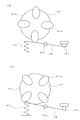
- Patent Document 1 discloses a dispensing device in which a plurality of chemical liquid bottles are mounted on a circular mounting body in plan view along the circumferential direction, and a chemical liquid is injected into each chemical liquid bottle via a nozzle. Is described.
- the chemical liquid stored in the chemical liquid bottle is a suspension
- the solid particles gradually dispersed in the liquid with time will become non-uniform, so it is necessary to agitate and homogenize before dispensing There is.
- the chemical liquid is agitated by sucking the chemical liquid in the chemical liquid bottle using the nozzle and returning the sucked chemical liquid into the chemical liquid bottle again.
- Patent Document 1 requires a separate storage chamber so that a sufficient amount of chemical solution can be sucked from the chemical solution bottle through the nozzle so that stirring can be performed appropriately.
- the object of the present invention is to provide a dispensing device that can sufficiently stir the chemical solution in the chemical solution bottle in a short time despite the simple configuration.
- Dispensing device A chemical solution that supports the plurality of chemical solution bottles so that a plurality of chemical solution bottles arranged in an annular region on substantially the same circumference moves along the circumferential direction of the annular region, and moves to a dispensing position of the annular region.
- This configuration makes it possible to sufficiently agitate the contained chemical solution in a short time despite the simple configuration of rotating the chemical solution bottle.
- the bottle support portion supports the plurality of chemical liquid bottles so as to be rotatable toward the inside of the annular region.
- the dead space inside the annular region in which the chemical liquid bottle is arranged can be used for the rotation of the chemical liquid bottle, and the small size of the dispensing device despite the configuration including a plurality of chemical liquid bottles. Can be realized.
- the bottle support section includes a first inclined position where the liquid bottle position is higher than a center position of the bottom surface of the chemical liquid bottle from a horizontal position, and a second inclined position symmetrical to the first inclined position with respect to the horizontal plane. It is preferable to oscillate within the rotation range.
- the chemical solution in the chemical solution bottle can be agitated in a short time, and the workability can be improved.
- the bottle support portion includes a plurality of rotation support portions, Each said rotation support part supports the said chemical
- This configuration makes it possible to rotate the chemical bottles supported by the plurality of rotation support portions with respect to one rotation drive portion, so that the configuration can be simplified and manufactured at low cost.
- the chemical liquid bottle is a bottomed cylindrical shape with a mouth formed at the upper end,
- the bottle support part preferably holds the mouth part and rotatably supports the chemical liquid bottle.
- the rotation range of the chemical bottle by the rotation drive unit includes a mounting position where the chemical bottle can be mounted on the bottle support unit with the mouth portion positioned above.
- This configuration makes it possible to smoothly attach and detach the chemical solution bottle.
- a closed portion that is provided in the bottle support portion and closes the mouth portion of the chemical liquid bottle; an air supply nozzle that extends through the closed portion toward the bottom surface of the chemical liquid bottle; and a chemical bottle that penetrates the closed portion. It is preferable to further include a chemical solution extraction portion having a chemical solution extraction nozzle that opens to the mouth portion.
- This configuration allows the chemical solution in the chemical solution bottle to be sufficiently stirred and then dispensed through the chemical solution dispensing unit.
- the bottle support part supports the chemical liquid bottle upside down so that the mouth part is on the lower side when the chemical liquid is poured out.
- This configuration makes it possible to smoothly dispense the chemical solution from the chemical solution bottle using the gravity acting on the chemical solution.
- the chemical liquid dispensing nozzle is composed of a flexible tube extending from the chemical liquid bottle, It is preferable to further include a chemical solution discharging mechanism for discharging the chemical solution in the chemical solution bottle into the patient bottle by making contact with and separating from the tube extending from the chemical solution bottle moved to the extraction position of the annular region. .
- This structure can further simplify the structure and can be manufactured at low cost.
- the chemical solution discharging mechanism is A first pressing member that crushes the tube and closes the flow path; A second pressing member that moves while pressing the tube from the upstream side in the flow direction of the chemical solution toward the pressing position rather than the pressing position by the first pressing member; When changing the pressing position with respect to the tube by the second pressing member, an interlocking member that releases the pressing state by the first pressing member and enables the chemical solution in the tube to flow, Should be provided.
- the medicinal solution bottle is attached to the medicinal solution dispensing portion at the mouth, It is preferable that the said chemical
- This configuration allows the chemical solution bottle to be attached to and detached from the bottle support portion with the chemical solution dispensing portion attached in advance to the mouth portion, so that workability can be greatly improved. Moreover, there is no fear that the chemical solution in the chemical solution bottle leaks during the attaching / detaching operation.
- the drug solution dispensing part is a plug member attached to the mouth part of the drug solution bottle, It is preferable that the plug member includes a bottle fastener that slides to be engaged with a bulging portion formed in the mouth portion and supports the drug solution bottle.
- This configuration makes it possible to attach the chemical solution dispensing portion to the mouth portion of the chemical solution bottle with a simple bottle stopper that can be simply slid.
- the bottle fastener is slidable so as to be engaged with a bulging portion formed in the mouth portion in a state where the chemical solution bottle is disposed at an appropriate position with respect to the plug member.
- the mouth portion of the chemical liquid bottle is formed with a male screw at the tip than the bulging portion, It is preferable that the chemical liquid dispensing portion is formed with a female screw into which a mouth portion of the chemical liquid bottle is screwed.
- a cleaning water supply unit that supplies cleaning water to each nozzle of the chemical solution dispensing unit included in the chemical solution bottle moved to the cleaning position of the annular region, and air is supplied to each nozzle that has moved to the drying position of the annular region It is preferable to further include a nozzle cleaning unit having an air supply unit.
- the cleaning water can be supplied and the waste water after cleaning can be collected in the cleaning water recovery unit simply by moving the chemical bottle to the cleaning position in the circumferential direction of the annular region. Furthermore, it can dry with the air supplied from an air supply part.
- the washing water supply unit is disposed below the annular region. In particular, it is preferable to arrange in the dead space of the apparatus main body.
- the air supply unit is disposed below the annular region. In particular, it is preferable to arrange in the dead space of the apparatus main body.
- the internal space of the apparatus main body can be used more efficiently, and the apparatus main body can be downsized.
- a diluent tank containing the diluent is further provided, A pivot arm that movably supports an injection tube extending from the diluent tank; The injection port of the injection tube is positioned at an injection position between the patient bottle located at the dispensing position and the drug solution bottle positioned above the patient bottle, and at a separated position away from the patient bottle.
- the pivot arm is preferably pivotable.
- the dilution liquid can be easily supplied into the patient bottle by simply rotating the injection tube with the rotation arm without moving the patient bottle or complicating the configuration. be able to.
- the chemical liquid dispensing part attached to the mouth part of each chemical liquid bottle includes a detected part that stores position information indicating which bottle support part is mounted, Before pouring the liquid medicine from the liquid medicine bottle containing the liquid medicine to be dispensed into the bottle for the patient, authentication is performed based on the position information stored in the detected part. It is preferable to further comprise a control means.
- a storage means When the chemical solution bottle is attached to the bottle support part, the control means stores the positional information stored in the detected part and the chemical information stored in the chemical liquid bottle to which the chemical liquid dispensing part having the detected part is attached. Are preferably stored in the storage means in association with each other.
- the position information and the chemical information can be associated with each other, so that different chemical solutions are not accidentally dispensed in the subsequent dispensing process.
- a bottle for a patient that collects a liquid medicine poured out from the liquid medicine dispensing section is placed, and a bottle placement section that can be raised and lowered,
- a bottle detection unit capable of specifying the position of the mouth of the patient bottle placed on the bottle placement unit;
- Control means for adjusting the position of the patient bottle relative to the drug solution dispensing unit by raising and lowering the bottle mounting unit based on positional information of the mouth of the patient bottle detected by the bottle detection unit; Is preferably further provided.
- the position of the mouth can be specified by the bottle detection unit, and the patient bottle can be automatically moved up and down to a position where it can be dispensed from the drug solution dispensing unit. it can.
- the chemical liquid dispensed from the chemical liquid dispensing unit is less likely to spill.
- the bottle mounting unit includes a weight detection unit that can detect the weight of a patient bottle to be mounted, including a drug solution to be filled, It is preferable that the control means controls a dispensing amount by the drug solution dispensing unit based on a weight of the patient bottle detected by the weight detection unit.
- the first dispensing process of dispensing the chemical solution by the first dispensing amount per unit time and the chemical solution before the unit time It is preferable to further comprise control means for executing a second dispensing process for dispensing each second dispensing amount that is smaller than the first dispensing amount.
- the drug solution is poured into the patient bottle in two stages, ie, the first and second dispensing processes.
- One of the dispensing processes is preferably performed by opening and closing a flow path from the chemical solution bottle to the patient bottle.
- This configuration makes it possible to freely change the dispensing amount while allowing easy and inexpensive production.
- One end opening is connected to the mouth of the drug solution bottle and extends downward, and a flexible tube capable of supplying the drug solution into the patient bottle through the other end opening;
- a first pressing member that can move to a closed position that blocks the flow of the chemical liquid that passes therethrough by pressing and deforming the tube, and an open position that permits the flow of the chemical liquid by releasing the pressure on the tube; , A closed position movable to the downstream side while maintaining a state of blocking the flow of the chemical liquid passing by pressing and deforming the tube on the upstream side of the pressing position by the first pressing member, and to the tube
- a second pressing member that is movable to an open position that releases the pressing of the liquid and allows the flow of the chemical liquid;
- the control means executes a maximum dispensing process for positioning the first pressing member and the second pressing member at an open position as the first dispensing process.
- the chemical solution can be quickly dispensed until immediately before the dispensing process is completed, and the efficient dispensing process can be executed.
- One of the dispensing processes is preferably performed by moving the pressing position of the flow path from the chemical solution bottle to the patient bottle toward the downstream side in the flow direction of the chemical solution.
- This configuration makes it possible to dispense a certain amount of chemical solution by moving the tube pressing position.
- One end opening is connected to the mouth of the drug solution bottle and extends downward, and a flexible tube capable of supplying the drug solution into the patient bottle through the other end opening;
- a first pressing member that can move to a closed position that blocks the flow of the chemical liquid that passes therethrough by pressing and deforming the tube, and an open position that permits the flow of the chemical liquid by releasing the pressure on the tube; , A closed position movable to the downstream side while maintaining a state of blocking the flow of the chemical liquid passing by pressing and deforming the tube on the upstream side of the pressing position by the first pressing member, and to the tube
- a second pressing member that is movable to an open position that releases the pressing of the liquid and allows the flow of the chemical liquid; With The control means moves the first pressing member to the open position from the state where the first pressing member and the second pressing member are positioned at the closed position as the second dispensing process, and moves the second pressing member to the open position.
- the chemical solution stored in the tube partitioned by the first pressing member and the second pressing member located at the closed position is moved by moving the closed position to the downstream side while maintaining the state of blocking the flow of the chemical solution passing therethrough. It is preferable to execute a small-volume dispensing process for performing small-volume dispensing that can be supplied to the patient bottle any number of times.
- Pressure detecting means for directly or indirectly detecting the air pressure in the chemical bottle; It is preferable that the control means controls the air supply amount by the air supply unit based on the detection result of the pressure detection means.
- This configuration prevents the amount of drug solution supplied to the patient bottle from increasing per unit time and causing weight detection errors. Further, even when a chemical solution having a high viscosity is stored in the chemical solution bottle, the air pressure is small and cannot be discharged. Furthermore, it is possible to detect whether air leakage has occurred.
- the control means may control the air supply amount by the air supply unit based on the detection result of the pressure detection means so that the air pressure in the chemical liquid bottle is constant.
- the control means controls the air supply amount by the air supply unit based on the detection result of the pressure detection means so that the flow rate per unit time of the chemical liquid dispensed from the chemical liquid bottle is constant. May be.
- the control unit may control an air supply amount by the air supply unit so that a pressure detected by the pressure detection unit in the second extraction process is smaller than that in the first extraction process. .
- the control means may control the amount of air supplied by the air supply unit such that the higher the viscosity of the chemical liquid stored in the chemical liquid bottle, the higher the pressure detected by the pressure detection means. Good.
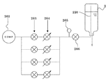
- the middle of the flow path for supplying air into the chemical bottle is composed of at least two flow paths with different amounts of air that can be supplied per unit time.
- the air pressure in the chemical solution bottle can be adjusted with a simple and inexpensive configuration in which the flow path is switched, and a good dispensing state of the chemical solution can be realized.
- a guide member having a guide groove for guiding the tube in an arc shape;
- the second pressing member preferably includes a second pressing portion that moves along the guide groove to press the tube and block the flow of the chemical solution.
- This configuration makes it possible to block the flow of the chemical solution in the tube even while moving the second pressing portion.
- the first pressing member is attached to the guide member so as to be rotatable about a first support shaft, and a first pressing portion capable of pressing the tube, and the tube is pressed by the first pressing portion.
- An urging section for urging It is preferable that the second pressing member includes a cam member that operates the first pressing member while maintaining a closed state in which the tube flow path is blocked by the second pressing portion.
- the second pressing member is provided to be rotatable around a second support shaft, A driving member for driving the second pressing member; It is preferable that the control means drives the second pressing member in the normal direction by the driving member and executes the small amount dispensing process.
- a single drive member dispenses a small amount of liquid to the patient bottle every time the tube is stored, and the tube is opened to continuously supply the liquid from the chemical bottle to the patient bottle.
- the maximum dispensing process can be executed, and the configuration can be simplified, downsized, and manufactured at low cost.
- the control means includes In the small volume dispensing process, the second pressing member is driven by the driving member, the first pressing portion of the first pressing member, and the storage position in which the chemical solution is stored in the tube by the second pressing portion; 2 A small amount pouring position where the pressing portion is moved to the downstream side while maintaining the pressing state, and the pressing state of the tube by the first pressing portion of the first pressing member is released by the cam member, and the tube by the second pressing portion Is performed by recirculating and moving the tube at the preparation position for resuming the pressing state of the tube by the first pressing portion.
- the second pressing member is driven by the driving member to release the pressing state by the second pressing portion, and the first pressing portion of the first pressing member is separated from the tube by the cam member. It may be executed by maintaining the open state.
- One end opening is connected to the mouth of the drug solution bottle and extends downward, and a flexible tube capable of supplying the drug solution into the patient bottle through the other end opening;
- a guide member having a guide groove for guiding the tube in an arc shape;
- a closed position that can move downstream while maintaining the state of blocking the flow of the chemical liquid that passes through by pressing and deforming the tube, and an open that allows the chemical liquid flow by releasing the pressure on the tube
- a pressing member having a pair of pressing parts movable to a position;
- the control means presses and deforms the tube by the pair of pressing portions, partitions the inside of the tube by the pair of pressing portions, stores the chemical solution, and the pair of pressing portions
- a small amount dispensing process for sequentially discharging the stored chemical solution is performed by circularly moving the part, and the tube is opened by separating the pair of pressing parts from the tube as the first dispensing process.
- the maximum dispensing process for continuously discharging the chemical solution may be performed.
- the tube can be fully opened until a desired dispensing amount is reached, and then a certain amount of the chemical solution stored in the tube can be supplied. That is, by finely adjusting the amount of the chemical solution supplied to the patient bottle immediately before reaching the desired dispensing amount, accurate dispensing can be performed while simplifying the configuration and manufacturing at low cost.
- the bottle support portion supports each chemical solution bottle upside down in the annular region so that the mouth portion of the chemical solution bottle is located on the lower side,
- the rotation drive unit is movable to a forward position where the bottle support unit can be operated and a retracted position separated from the bottle support unit, It is preferable that an attachment / detachment space in which the chemical solution bottle rotated by the rotation driving unit is located below the advance position.
- the space for attaching / detaching can be made sufficiently wide, and the attaching / detaching operation of the chemical solution bottle can be performed smoothly.
- the bottle support portion supports each chemical solution bottle upside down in the annular region so that the mouth portion of the chemical solution bottle is located on the lower side, A mouth part of the chemical liquid bottle, a closing part for closing the mouth part of the chemical liquid bottle, an air supply nozzle extending through the closed part to the bottom surface side of the chemical liquid bottle, and a chemical liquid bottle penetrating the closing part And a flexible tube that opens to the mouth of A chemical solution discharge mechanism for discharging the chemical solution in the chemical solution bottle into the patient bottle by contacting and separating from the tube,
- the chemical solution discharge mechanism can be moved to a forward position where the chemical solution can be dispensed by making contact with and separating from the tube, and a backward position separated from the dispensing position, It is preferable to arrange an extraction space in which a patient bottle can be placed below the advance position.
- the dispensing space can be made sufficiently wide and the patient bottle can be placed and taken out smoothly.
- the chemical solution in the chemical solution bottle can be rapidly and sufficiently agitated despite the simple configuration in which the bottle support portion is driven to rotate the chemical solution bottle.
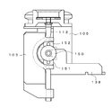
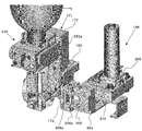
- FIG. 2 is a schematic plan view showing the internal structure of FIG. 1 (the chemical bottle is rotated to a horizontal position).
- FIG. 1 the chemical bottle is rotated to a horizontal position.
- FIG. 1 the chemical bottle is rotated to a horizontal position.
- FIG. 1 the chemical bottle is rotated to a horizontal position.
- FIG. 1 the chemical bottle is rotated to a horizontal position.
- FIG. 1 the chemical bottle is rotated to a horizontal position.
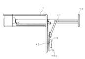
- FIG. 2 is a schematic partial front view which shows the support structure of the cyclic
- FIG. the chemical
- FIG. 8 is a plan view of FIG. 7. It is a schematic side view which shows the structure of the rotation support part of FIG. It is a schematic plan view which shows the bottle support part of FIG. It is a schematic front view which shows the dilution water injection
- FIG. 1 It is a schematic plan view of the dispensing apparatus which concerns on 2nd Embodiment. It is a partially broken side view which shows the bottle support part of FIG. It is a figure which shows the state which rotated the cam member and the 2nd press member counterclockwise from the state shown in FIG. It is a figure which shows the state which rotated the cam member and the 2nd press member further counterclockwise from FIG. It is a top view of the action
- FIG. 30 is a perspective view showing a support base of the lock mechanism and the rotation support portion of FIG. 29. It is a perspective view which shows the state which added the rotation part to FIG. It is a perspective view which shows the rotation drive part of FIG. It is a perspective view which shows the state which looked at FIG. 32 from the other side.
- FIG. 37 is a bottom view of the plug body of FIG. 36. It is a perspective view which shows the moving member provided in the extraction
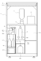
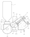
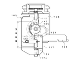
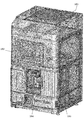
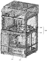
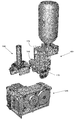
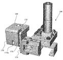
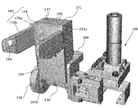
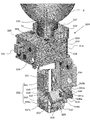
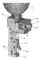
- (First embodiment) 1 and 2 show a dispensing apparatus according to the first embodiment.
- the dispensing device includes a bottle support portion 3 that rotatably supports a plurality of chemical liquid bottles 2 on a substantially rectangular parallelepiped device main body 1, and each bottle support portion 3.
- Rotation drive unit 4 for rotating the drug solution bottle 2, drug solution dispensing unit 5 for dispensing the drug solution stored in each drug solution bottle 2, and dilution water for injecting dilution water into the patient bottle 6
- An injection unit 7, a nozzle cleaning unit 8 for cleaning the nozzles used in the chemical solution dispensing unit 5, and a control device 9 for driving and controlling these components are provided.
- the apparatus main body 1 has a substantially rectangular parallelepiped frame shape, and the surface is covered with a panel.
- a holding plate 10 on which the control device 9 is arranged is attached to the upper part of the apparatus main body 1.
- the holding plate 10 can be pulled forward together with the first front panel 12 along an extendable support rail 11 extending in the front-rear direction.
- the holding plate 10 is rotatably connected to the support rail 11 on both sides of the rear end portion, and can be rotated downward by grasping a handle 10a provided at the front end portion.
- the control device 9 attached to the holding plate 10 can be exposed to the front surface, and operations such as maintenance can be easily performed.
- a second front panel 13 is disposed below the first front panel 12.
- the second front panel 13 is attached to the apparatus main body 1 in FIG. 1 so as to be openable and closable around the right end as a rotation center, and can be opened and closed by grasping the handle 13a at the left end.
- a bottle support portion 3, a rotation drive portion 4, and the like which will be described later, are disposed.
- the second front panel 13 is provided with a display 14 composed of a liquid crystal touch panel or the like, and a payout opening 13b through which paper printed by the journal printer 15 is discharged is formed on the side of the display 14.
- a first drawer 16 is provided in the upper left part of the lower area of the second front panel 13, and a dilution water tank 17 and a washing water tank 18 are disposed there. Yes.
- the first drawer 16 can be pulled forward by pulling the handle 16 a and can be poured into the dilution water tank 17 and the washing water tank 18.
- a discharge port 19 through which a label printed by the label printer 20 is discharged is formed below the first drawer 16.
- a bottle mounting portion 60 is provided on the upper side so that the patient bottle 6 can be placed and the medicine from the drug solution dispensing portion 5 can be injected as will be described later. It has been.
- a second drawer 21 is provided below the bottle mounting unit 60, and a waste liquid recovery tank 22 is disposed there.
- the second drawer 21 can be withdrawn forward by pulling the handle 21a to discard the waste liquid.
- an open / close door 23 (FIG. 1) is provided so as to be rotatable around the right edge.
- the open / close door 23 can be opened and closed by grasping a handle 23a provided at the left center portion.
- a storage chamber 24 capable of storing the patient bottle 6 and the like is formed.
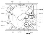
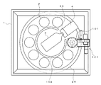
- the bottle support portion 3 supports an annular support 26 on a support plate 25 provided in the apparatus main body 1, and further, a plurality of rotation support portions 27 (see FIG. 6).
- the support plate 25 is formed with an opening 28 in the center, and interference when a chemical bottle 2 described later rotates is avoided.
- the support plate 25 is provided with a first guide roller 29a and a second guide roller 29b respectively disposed at four locations on the same circumference, a drive motor 32 having a drive gear 31 on a rotating shaft, and an encoder 33. It has been.
- the annular support 26 is formed by connecting inner edges of annular plates 34 a, 34 b arranged vertically at a predetermined interval by a plurality of connecting rails 35.
- the lower annular plate 34b includes a ring portion 36 and a gear portion 37 that is disposed on the lower side of the ring portion 36 and has a smaller diameter than the ring portion 36.
- the upper annular plate 34a is guided by a guide roller 30 that can roll on its upper surface.
- the lower annular plate 34b is rotatably supported by the ring portion 36 being supported by the first guide roller 29a and the second guide roller 29b at four locations (8 locations in total) on the outer peripheral surface and the annular lower surface. ing.
- a drive gear 31 provided on the rotation shaft of the drive motor 32 is engaged with the gear portion 37.
- the drive gear 31 is biased toward the gear portion 37, but can be separated from the gear portion 37 by operating the operation portion 31 a connected by a wire.
- the rotation of the annular support 26 is detected by the encoder 33 so that the position of the chemical bottle 2 supported by which rotating support 27 can be specified.
- the control device 9 which will be described later controls the rotation of the drive motor 32 based on the detection signal from the encoder 33, rotates the annular support 26, and places the chemical liquid bottle 2 supported by the rotation support portion 27 at a desired position ( (Moving position, pouring position, cleaning position, drying position).
- the encoder 33 can be dispensed with.
- the rotation range of the annular support 26 is a range of one rotation each in the forward and reverse directions.
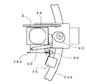
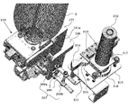
- the rotation support portion 27 includes a support base 38 that is removably attached to the ring portion 36 of the lower annular plate 34b by screwing or the like, and a support shaft 39a centered on the support base 38. And a rotating part 39 connected rotatably.
- the support base 38 is provided with a first pinch valve 40.
- the first pinch valve 40 is configured by a substantially L-shaped drive arm 41 provided so as to be rotatable about a support shaft 41a, and one end side thereof further extends vertically upward.
- the drive arm 41 swings between the clamping position and the release position by rotating the arm cam 43 by driving the arm motor 42, and can be positioned at one of these two positions and one of these intermediate positions. It has become.
- the first pinch valve 40 clamps a first nozzle 51 (to be described later) to deform the shape, and the flow path is fully closed to prevent the outflow of the chemical solution.
- the flow rate of the chemical solution that is, the discharge amount can be limited to almost half. It should be noted that the deformation amount of the first nozzle 51 by the first pinch valve 40 can be adjusted in multiple steps or steplessly.
- the rotating portion 39 is obtained by integrating the bottle mounting portion 45 with the rotating portion main body 44.
- the chemical solution bottle 2 can be attached to and detached from the bottle mounting portion 45.
- the chemical liquid bottle 2 has a bottomed cylindrical shape, and its cross-sectional area gradually decreases toward the top end 46.
- a support recess 47 is formed in the central portion of the bottle mounting portion 45.
- the mouth 46 of the chemical liquid bottle 2 is detachably attached to the support recess 47.
- at least a portion (bottom surface) with which the mouth portion 46 of the chemical liquid bottle 2 abuts is made of an elastic material such as rubber.
- the rotation member 39 is provided with a locking member 48.
- the locking member 48 is locked to a male screw portion 46 a formed on the outer peripheral surface of the mouth portion 46, and maintains the mouth portion 46 in pressure contact with the bottom surface of the support recess 47.
- the rotating portion 39 is attached to a substantially semicircular driven gear portion 49 on a support shaft provided in the rotating portion main body 44, and this driven gear portion 49 is driven by the rotating drive portion 4 described later. It is possible to rotate between an attachment position that is meshed with the gear portion 58 and turned upside down and an attachment / detachment position that is rotated 180 degrees and the mouth portion 46 is positioned above. As shown in FIG. 8, the rotating portion 39 is rotated between the mounting position and the attaching / detaching position. As shown in FIG. 8, the operation piece 36b provided integrally is an optical sensor 50 including a light emitting element and a light receiving element provided at each position. Judgment is made based on whether or not the optical path is interrupted.
- a first nozzle 51 and a second nozzle 52 made of a flexible resin material pass through the support recess 47, respectively.
- One end of the first nozzle 51 protrudes from the bottom surface of the support recess 47 by a predetermined dimension and is located near the mouth 46 of the chemical bottle 2, and the other end protrudes from the bottle mounting part 45 by a predetermined dimension downward.
- one end side of the second nozzle 52 extends to the vicinity of the bottom surface of the chemical liquid bottle 2 to be attached.
- the other end side of the 2nd nozzle 52 is pinched by the said drive arm 41, and the outflow of the chemical
- the other end portion of the second nozzle 52 extends to a side portion of the rotating portion 39 via the tube 52a, and is opposed to an air nozzle 73a, which will be described later, so as to be able to contact and separate.
- the rotation drive unit 4 is attached to a mounting base 53 attached to the support plate 25, and drives the first motor 54 to advance and retract the ball screw 57 through the pulleys 55 a and 55 b and the belt 56.
- the drive gear portion 58 can reciprocate.
- the drive gear unit 58 meshes with the driven gear unit 49 of the rotating unit 39 at the forward movement position.
- the drive gear part 58 rotates forward / reversely via the gear which is not illustrated by the drive of the 2nd motor 59, and rotates the rotation part 39 between an attachment position and an attachment / detachment position.
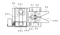
- the medicinal solution dispensing unit 5 includes a bottle placing unit 60 for placing the patient bottle 6 filled with the dispensed medicinal solution, and a second nozzle 52 in the medicinal solution bottle 2.
- the air supply part 61 which can supply air via is provided.
- the bottle mounting unit 60 includes a mounting plate 64 that moves up and down by driving the second lifting motor 62 and operating the lifting ball screw 63 via the pulleys 62a and 62b and the belt 62c.
- the weight of the patient bottle 6 placed on the placement plate 64 can be detected by the weight detection sensor 65.
- a pair of clamping pieces 66 is provided above the mounting plate 64. As shown in FIG. 10, each holding piece 66 is formed with a hold surface 66a having a concave facing surface and a guide surface 66b spaced from the hold surface 66a toward the front end side.
- the sandwiching pieces 66 are guided by four guide rods 67 so that they can be opened and closed, and interlocking gears 69 are engaged with racks 68 provided respectively.
- each clamping piece 66 opens and closes in conjunction. Moreover, each clamping piece 66 is urged
- the mouth portion 46 of the patient bottle 6 placed on the placement plate 64 is detected by a lift position detection sensor 70 (FIG. 9).
- the driving of the second lifting / lowering motor 62 is controlled by the control device 9 described later based on a detection signal from the lifting / lowering position detection sensor 70.
- the patient bottle 6 can be positioned at the initial position, the chemical solution injection position where the chemical solution can be injected from the first nozzle 51, and the dilution water injection position by the dilution water injection unit 7 described later. .
- the air supply unit 61 includes an elevating plate 72 that moves up and down between a connection position and a separated position by driving the first elevating motor 71 and rotating a cam 71a provided on the rotation shaft thereof.
- An air nozzle 73 a extending from the pump 73 is connected to the elevating plate 72.
- the air nozzle 73a is connected to the second nozzle 52 by raising the elevating plate 72 to the connection position. Then, by driving the pump 73, air is supplied into the chemical liquid bottle 2, and the stored chemical liquid is forcibly discharged from the first nozzle 51 with the air pressure.
- medical solution extraction from the 1st nozzle 51 may not be forced discharge using an air pressure, and you may make it discharge
- a separate opening / closing valve is provided at a predetermined location (for example, a lower end opening facing the air nozzle 73a) of the tube 52a, and the air nozzle 73a is connected when the lifting plate 72 is raised, and the lifting plate 72 contacts the opening / closing valve to open / close.
- the valve may be opened so that the connection of the air nozzle 73a is released when the elevating plate 72 is lowered, and the elevating plate 72 is separated from the on / off valve to close the on / off valve.
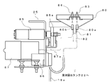
- the dilution water injecting section 7 is for injecting cleaning water contained in a dilution water tank 17 (FIG. 2) provided on the lower side of the apparatus body 1 into the patient bottle 6. is there.
- the dilution water injection part 7 includes an injection tube 74, a swing support part 75, and a swing arm 76 provided on the swing support part 75 so as to be rotatable about a support shaft 76a.
- the injection tube 74 is inserted into a dilution water tank 17 provided at one end on the lower side of the apparatus main body 1, passes through the rotation arm 76 from the swing support portion 75, and the other end is a lower surface of the distal end of the rotation arm 76.
- the injection port 76b is located in the position.
- the swing support portion 75 is provided with a first tube pump 77 and a rotation motor 78.
- the first tube pump 77 acts on the injection tube 74 and discharges the cleaning water stored in the dilution water tank 17 from the injection port 76 b on the distal end side of the rotating arm 76.
- the rotation motor 78 rotates the rotation arm 76 through the gears 78a and 78b by driving.
- the rotation range of the rotation arm 76 is detected by the sensor 76c, and is positioned at the water pouring position and the retreat position.
- a second pinch valve 79 is provided on the distal end side of the rotating arm 76 so as to be able to block the flow of cleaning water that passes through the injection tube 74 in pressure contact therewith.
- the second pinch valve 79 is controlled to be opened and closed by a drive motor and a cam (not shown).
- the nozzle cleaning unit 8 includes a cleaning dish 80 attached to a support plate 25 provided in the apparatus main body 1 so as to be movable up and down.
- the washing dish 80 has a substantially inverted conical shape, and a waste water port 81 is formed at the center of the bottom surface, and a waste water tube 82 extending to the waste liquid recovery tank 22 is connected thereto.
- a cleaning nozzle 83 and an air supply nozzle 84 are connected to the cleaning dish 80 through through holes 80a and 80b formed at two locations around the waste water outlet 81, respectively.
- a vertical movement motor 85, a second tube pump 86, and a compressor 87 are attached to the support plate 25.
- a cam 85a is integrated with the rotary shaft of the vertical movement motor 85, and the washing dish 80 can be moved up and down via the cam 85a.
- One end of the second tube pump 86 acts on the tube 18a inserted in the cleaning water tank 18, and the cleaning water stored in the cleaning water tank 18 is ejected from the cleaning nozzle 83 through the tube 18a.
- the compressor 87 ejects air from the air supply nozzle 84 via the tube 87a.
- control device 9 includes a control unit 88 and a storage unit 89.
- the control unit 88 refers to the data stored in the storage unit 89 on the basis of prescription data input from the server 90 via a LAN or the like and input signals from the sensors.
- the chemical liquid bottle 2 mounted on the bottle mounting portion 45 is rotated by driving and controlling the components, and the chemical liquid bottle 2 is rotated to agitate the stored chemical liquid.
- a series of dispensing processes such as pouring the chemical solution into the bottle 6, diluting the chemical solution with dilution water, washing the first nozzle 51, and drying are controlled.
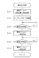
- the medicinal solution bottle 2 filled with the medicine (the first medicine when there are a plurality of medicines) included in the prescription data is specified (step S2).
- the chemical liquid bottle 2 is mounted on each rotation support portion 27 of the bottle support portion 3 in advance, the medicine to be stored and the rotation support portion 27 to be mounted are associated with each other. This is performed based on the data stored in the storage unit 89.
- step S3 it is determined whether or not stirring is required before the contained chemical solution is dispensed. This determination uses data stored in the storage unit 89 in advance as information (chemical solution information) regarding the chemical solution stored in the chemical solution bottle 2. If it is determined that the agitation is necessary, the rotation support portion 27 to which the corresponding chemical liquid bottle 2 is attached is positioned at the rotation position by driving the drive motor 32 and rotating the annular support body 26 ( Step S4). Then, by driving the first motor 54 of the rotation drive unit 4, the drive gear 58 is advanced and meshed with the driven gear unit 49 of the rotation support unit 27 (step S5).
- step S6 the rotation support portion 27 is rotated, and the chemical liquid bottle 2 attached thereto is moved between the attachment position and the attachment / detachment position (step S6).
- the rotation direction of the chemical liquid bottle 2 is the inside of the chemical liquid bottle 2 arranged on substantially the same circumference, that is, a dead space where no parts are arranged. Therefore, the chemical solution in the chemical solution bottle 2 can be agitated without increasing the size of the apparatus. And since the chemical
- step S7 A patient bottle 6 to be poured out by an operator in advance is set at the dispensing position.
- the patient bottle 6 may be set by automatically selecting an appropriate size and displaying it on the display 14 based on the prescription data.
- the mouth 46 is detected by the detection sensor, and the second elevating motor 62 is driven and controlled based on this detection signal, so that the placing plate 64 is moved up and down to raise the patient bottle 6. Is positioned at the dispensing standby position (step S8), and the chemical solution dispensing process is started (step S9).
- the arm motor 42 is driven to press-contact the second nozzle 52 to rotate the drive arm 41 from the clamping position to the open position (step S21). Then, the first nozzle 51 is fully opened (step S22). Further, the compressor 87 is driven to supply air into the chemical liquid bottle 2 (step S23), and the internal pressure is increased, thereby smoothing out the chemical liquid.
- the first nozzle 51 is fully opened and air is supplied into the chemical liquid bottle 2 to determine how much chemical liquid is discharged per unit time for each chemical bottle containing different types of chemical liquids.
- a database is prepared in advance by experiments or the like and stored in the storage unit 89. And based on this database, the chemical
- step S24 Thereafter, by reaching the set amount before reaching the desired amount of the chemical solution (step S24), the drive arm 41 is rotated to the intermediate position (step S25), and the amount of the dispensed chemical solution is suppressed.
- the chemical liquid becomes a desired amount determined by the prescription data (the volume of the chemical liquid converted from the weight based on the specific gravity of the chemical liquid).
- Step S26 the drive arm 41 is rotated to the clamping position, and the dispensing of the chemical solution is stopped (Step S27).
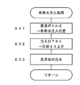
- step S10 it is determined whether or not the diluting water needs to be poured. If it is determined that dilution water injection is necessary, the dilution water injection process is started (step S11).
- the mounting plate 64 is lowered to position the chemical bottle 2 at the dilution water injection position based on the detection signal from the lift position detection sensor 70 (step S31). And the rotation arm 76 of the dilution water injection
- step S12 the drive motor 32 is further driven to rotate the annular support 26 to move the corresponding chemical solution bottle 2 to the cleaning position.
- the process is started (step S13).
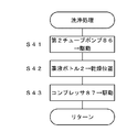
- the second tube pump 86 is driven to eject the cleaning water in the cleaning water tank 18 from the cleaning nozzle 83 ( Step S41). Thereby, the lower end portion of the first nozzle 51 is washed.
- the waste water after washing flows to the center of the bottom by the washing dish 80 and is collected from the waste water outlet 81 to the waste water tank through the waste water tube 82.
- the driving motor 32 is further driven to rotate the annular support 26 and move the chemical bottle 2 to the drying position (step S42). Then, the compressor 87 is driven to blow air to the first nozzle 51 via the air supply nozzle 84, and the attached cleaning water is dried (step S43).
- the space at the central portion surrounded by the attached chemical liquid bottle 2 that was originally a dead space is used for the stirring of the chemical liquid in the chemical liquid bottle 2. It can be used effectively as a moving area. For this reason, a chemical
- medical solution can be stirred, without enlarging an apparatus. Further, since the chemical liquid bottle itself is rotated, the chemical liquid can be sufficiently stirred. In addition, since the rotation drive unit 4 need only be provided at one place, the structure is not complicated and the cost is not increased.
- the present invention is not limited to the configuration described in the first embodiment, and various modifications can be made.
- the amount of the chemical liquid poured out from the chemical liquid bottle 2 into the patient bottle 6 is adjusted using a pinch valve, but the following configuration is also possible.
- two types of tube pumps one having a large delivery flow rate per unit time and one having a small delivery flow rate (may be three or more types having different delivery flow rates per unit time), are prepared.
- only one motor stepping motor, servo motor, etc.
- a tube pump having a large delivery flow rate is used until the set value before reaching the desired amount determined by the prescription data, and the set value is reached. For example, switch to a tube pump with a small delivery capacity.
- the dispensing process is performed by using a plurality of tube pumps without increasing the number of expensive motors, so that the dispensing error can be suppressed while realizing the optimum dispensing speed. .
- the cost is not increased so much.
- the tube 18a is opened and closed by the pressing member 92 that rotates about the support shaft 92a, and a fixed amount (for example, 5 ml) is used for the patient. You may make it supply a chemical
- the pressing member 92 is biased by a spring 93 so as to contact the outer periphery of the opening / closing cam 91.
- the tubes 18a, 52a and the like are used as they are.
- a coil spring is provided on the outer periphery, for example, the tubes 18a, 52a and the like are moved when the chemical bottle is rotated. It is preferable in that it can be prevented from being bent or stretched and its durability can be improved.
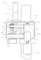
- FIG. 18 shows a dispensing device according to the second embodiment. Since this dispensing apparatus basically has the same configuration as that according to the first embodiment, the description of the same configuration is omitted, and the difference will be described below.
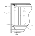
- the bottle support unit 101 includes a support base 102 and a guide member 103 fixed to the support base 102.
- the support base 102 includes a ceiling portion 104 and a pair of opposing side surface portions 105 extending downward from both side edge portions (a side surface portion located on the front side in FIG. 19 is not shown).
- a circular opening 106 is formed in the ceiling 104.
- a bottle mounting portion 107 is fixed to the upper surface of the ceiling portion 104.
- the bottle mounting portion 107 is made of an elastic material such as rubber, and includes a flat portion 108 screwed to the upper surface of the ceiling portion 104 of the support base 102 and a cylindrical portion 109 formed on the upper surface thereof.
- a first flow path connecting portion 110 and a second flow path connecting portion (not shown) are formed in the flat portion 108 in a region surrounded by the cylindrical portion 109, and the flat portion 108 communicates vertically. Yes.
- a female screw is formed on the inner peripheral surface of the cylindrical portion 109, and a male screw formed at the mouth of the chemical liquid bottle 2 can be screwed.
- One end of the tube 112 is connected to the lower end of the first flow path connecting part 110.
- the second flow path connecting portion is connected to the upper end portion of the first nozzle 51 extending into the chemical bottle 2 attached to the cylindrical portion 109, and to the lower end portion of the tube 52a.
- the bottle mounting portion 107 preferably has at least the second nozzle 52 integrated (the first nozzle 51 may be integrated) and is detachable from the support base 102.
- the bottle mounting part 107 integrated with the second nozzle 52 can be attached to the mouth of the chemical liquid bottle 2 in advance, the chemical liquid can be attached by mounting the chemical liquid bottle 2 as described above.
- the operation of inserting the second nozzle 52 into the inside of the bottle 2 becomes unnecessary, and the mounting operation to the bottle support portion 101 can be performed quickly and smoothly. Further, when the chemical bottle 2 is removed, there is no concern that the second nozzle 52 is exposed and the chemical liquid remaining in the second nozzle 52 leaks out.
- a pressure sensor (not shown) is provided in the middle of the air path from the first nozzle 51 to the pump 73 (for example, in the middle of the tube 52a), and the air pressure in the chemical liquid bottle 2 is detected.
- the pump 73 is driven and controlled based on the value detected by the pressure sensor so that the air pressure in the chemical liquid bottle 2 is maintained at a predetermined value. According to this, the air pressure in the chemical solution bottle 2 becomes too high, the amount of the chemical solution supplied to the patient bottle 6 increases per unit time, and the detection error by the weight detection sensor 65 does not occur. Further, by increasing the air pressure according to the viscosity of the chemical liquid stored in the chemical liquid bottle 2, there is no possibility of defective discharge.
- the pressure detected by the pressure sensor does not increase even though the rotational speed of the pump 73 is increased.
- the adjustment of the air pressure in the chemical liquid bottle 2 based on the value detected by the pressure sensor may be changed according to the chemical liquid amount.
- the amount of the chemical solution in the chemical solution bottle 2 is calculated based on the detected amount of the chemical solution based on the detection value of the weight detection sensor 65, or the discharged chemical solution is directly detected by the flow sensor, and the obtained discharge amount Is obtained by subtracting from the initial amount of the chemical solution in the chemical solution bottle 2. According to this, the remaining amount of the chemical liquid in the chemical liquid bottle 2 is reduced, and it is not difficult to discharge the chemical liquid due to its own weight, and quick dispensing can be performed to the end.
- a rotating piece 113 is supported on the other side surface portion (side surface portion opposite to the side surface portion 105 to which the guide member 103 is fixed) of the support base 102. It is attached so as to be rotatable around 113a.
- the rotating piece 113 has a substantially fan shape, and a linear portion extending in the radial direction from the support shaft side is bent in a direction orthogonal to form a contact portion.
- the guide member 103 has an arcuate guide groove 114 formed from the upper end to the lower end at the center of the side surface. Guide pieces 115a and 115b project from both ends of the guide groove 114, respectively. A tube 112 described later is disposed in the guide groove 114. A through hole 103 a through which the tube 112 is inserted is formed on the lower side of the guide member 103. A first pressing member 117 is attached to the vicinity of the through hole 103a so as to be rotatable about a support shaft 117a. Further, the guide member 103 is fixed with a support guide 116 for guiding a support shaft 138a which is a rotation center of a cam member 139 and a second pressing member 145, which will be described later.
- the first pressing member 117 includes a thin upper portion 118, a thick intermediate portion 119, and a lower portion 120 that extends from one side of the intermediate portion 119 and is provided with a support shaft 117a.
- first protrusions 121 and second protrusions 122 are formed at two positions in the width direction, respectively.
- a rotation piece 113 (described later) and a protrusion 143 of the cam member 139 are in contact with and pressed against the protrusions 121 and 122, respectively.
- a concave portion 123 that is recessed from the upper portion 118 and the lower portion 120 is formed at the side edge portion of the intermediate portion 119.
- the recess 123 is formed with a first pressing portion 124 that protrudes in the same direction as the support shaft 117a.
- the first pressing part 124 plays a role of pressing the tube 112 and closing the flow path, or separating and opening the tube 112.
- a locking hole 125 is formed in the intermediate portion 119, and a coil spring 126 is locked between the locking hole 125 and a locking shaft 103 b fixed to the guide member 103. Accordingly, the first pressing member 117 is urged counterclockwise in FIG. 19 around the support shaft 117a, and is positioned at the closed position where the first pressing portion 124 closes the flow path of the tube 112. .
- an operation unit 127 is attached to the apparatus main body 1.
- the operation unit 127 is provided at the pouring position of the apparatus main body 1 and includes a mounting frame 128 and a sliding member 129 slidably supported on the mounting frame 128 as shown in FIG. is there.
- the mounting frame 128 has a rectangular frame shape, and two sliding rails 130 are juxtaposed between a pair of opposing side walls.
- the sliding motor 131 is attached to the outer surface of one of the other set of side walls of the mounting frame 128, and the rotation motor 132 is attached to the outer surface of the other side wall.
- the sliding member 129 is slidably attached to the sliding rail 130 via the bush 133. Then, when the sliding motor 131 is driven to rotate forward and backward, the sliding member 129 is moved forward and backward through the pinion 131a and the rack 131b provided on the rotating shaft, respectively. Positioning is possible.
- the operating position and the standby position are specified by detecting a part of the detected plate 134 attached to the upper surface of the sliding member 129 by the first sensor 135 and the second sensor 136 provided on the side surface of the attachment frame 128, respectively.
- the positioning can be performed by driving and stopping the sliding motor 131. As shown in FIG.
- the sliding member 129 includes a top plate and side plates extending downward from both side edge portions thereof, and a mounting plate 138 extending further forward is fixed to the side plate.
- a cam member 139 and a second pressing member 145 are integrally attached to the attachment plate 138 so as to be rotatable about a support shaft 138a.
- the cam member 139 is made of a metal plate, and is supported on the mounting plate 138 so as to be rotatable forward and backward about the support shaft 138a.
- a first pulley 140 is provided on the support shaft 138 a, and power is transmitted by a belt 142 that extends between the first pulley 140 and a second pulley 141 that is rotationally driven by a rotation motor 132.
- On the outer peripheral edge of the cam member 139 an extended region is formed that bulges in the outer diameter direction within a predetermined angle range from the support shaft 138a that is the rotation center. In FIG. 19, a part of the extended region on the counterclockwise direction side is a protruding portion 143 that further protrudes.
- the protrusion 143 presses the second protrusion 122 of the first pressing member 117 when the cam member 139 rotates counterclockwise about the support shaft 138a, and the first pressing member 117 is centered on the support shaft 117a. And rotate clockwise.
- a pressing roller 144 is attached to a part of the extended region on the clockwise direction side. The pushing roller 144 pushes and turns the turning piece 113 when the cam member 139 is turned clockwise about the support shaft 138a. Thereby, the rotating piece 113 presses the first protrusion 121 of the first pressing member 117, and the first pressing member 117 is rotated clockwise about the support shaft 117a.
- the second pressing member 145 has a configuration in which a pressing roller 147 is rotatably attached to a support piece 146 fixed to the cam member 139 as shown in FIG.
- the thickness of the pressing roller 147 is set to be slightly smaller than the width dimension of the guide groove 114 of the guide member 103.
- the pressing roller 147 is also rotated around the support shaft 138a together with the cam member 139.
- the support shaft 138 a is guided by a support shaft guide 116 fixed to the guide member 103. Therefore, the rotation trajectory of the pressing roller 147 can be set to a position along the guide groove 114 with high accuracy. Then, while the pressing roller 147 moves through the guide groove 114, the tube 112 disposed therein is pressed to maintain the flow path in a closed state.
- a fall prevention member 148 supported by a plurality of support bars (not shown) protruding downward is attached to the ceiling surface of the apparatus body 1.
- This overturn prevention member 148 is formed by cutting out a part of the annular body into a substantially C shape, and reliably prevents the chemical solution bottle 2 arranged in an annular shape from accidentally falling over. Further, the notch portion is located just at the rotation position, and the rotation of the chemical liquid bottle 2 is allowed.
- magnets are provided at two positions on the side surface of the driven gear portion 49, and the rotation range of the chemical liquid bottle 2 is regulated by detecting the position of each magnet with a sensor (not shown). It is preferable to do this.
- the inside of the fall prevention member 148 is rotated through the notch, and beyond the position directed vertically downward to the attaching / detaching position directed obliquely downward on the front side of the apparatus (about It can be rotated (within a range of 200 °). Since the chemical solution bottle 2 can be attached and detached while being directed obliquely downward at the attachment / detachment position, the workability is excellent.
- the rotation of the chemical liquid bottle 2 is performed by detecting a magnet provided in the driven gear portion 49, there is no electrical component provided on the annular support 26 to which the chemical liquid bottle 2 is mounted. Therefore, the electric wire for power supply to the annular support 26 side is not required, and the rotation range of the annular support 26 is limited to the range of one rotation each in the forward and reverse directions as in the configuration of the first embodiment. There is no. That is, the restriction on the rotation range of the annular support 26 can be eliminated.
- the rotation of the annular support 26 may be managed based on detection signals from the encoder 33 and the origin sensor.
- the operation of the dispensing apparatus according to the second embodiment is substantially the same as that according to the first embodiment, but the stirring process when stirring the chemical liquid stored in the chemical liquid bottle 2, and the chemical liquid bottle 2 To the patient bottle 6 is different from the dispensing process.
- the chemical solution bottle 2 can sufficiently agitate the chemical solution and minimize the rotation range to shorten the agitation time.
- the liquid surface position is the center position of the bottom surface.
- An inclination angle exceeding (the vertical center position when the chemical liquid bottle 2 is set to the horizontal position) is calculated.
- medical solution bottle 2 is rock
- medical solution bottle 2 can be fully stirred. Further, the swing range does not become larger than necessary, and the stirring time can be shortened.
- the rotation angle is set before the chemical solution amount becomes less than half.
- a minimum fixed value may be used.
- the rotation range can be determined not only by the liquid level position of the chemical liquid on the bottom surface of the chemical liquid bottle 2, but also by the liquid level position on the side surface of the chemical liquid bottle 2. Further, by experiment, the amount of the chemical solution stored in each chemical solution bottle 2 may be changed to determine the minimum turning range in which it is determined that the chemical solution can be sufficiently stirred.
- the sliding motor 131 is driven to advance the sliding member 129 (step S51). Then, based on the detection signal from the first sensor 135 (step S52), the driving of the sliding motor 131 is stopped (step S53), thereby positioning the sliding member 129 at the operating position. At this time, the support shaft 138 a provided on the mounting plate 138 of the sliding member 129 is guided by the support shaft guide 116, and the cam member 139 and the second pressing member 145 are accurately positioned with respect to the guide member 103.
- the cam member 139 is rotated in the clockwise direction in FIG. 19 by forwardly driving the rotation motor 132 (step S54). Accordingly, the pushing roller 144 provided on the cam member 139 presses the rotating piece 113, and the rotating piece 113 rotates counterclockwise about the support shaft 113a. The rotating piece 113 presses the first protrusion 121 of the first pressing member 117, and the first pressing member 117 rotates clockwise about the support shaft 117a. As a result, the first pressing portion 124 of the first pressing member 117 is separated from the tube 112, and the chemical solution in the chemical solution bottle 2 flows out to the patient bottle 6.
- the supply of the chemical solution to the patient bottle 6 is performed until a predetermined dispensing amount (for example, a value 20 ml smaller than the dispensing amount) immediately before the dispensing amount obtained from the prescription data is reached.
- a predetermined dispensing amount for example, a value 20 ml smaller than the dispensing amount
- the dispensing is continued until the weight of the drug solution in the patient bottle 6 obtained by subtracting the weight of the patient bottle 6 from the weight detected by the weight detection sensor 65 reaches the predetermined dispensing amount.
- the dispensing may be continued until the time when the predetermined dispensing amount is expected to be reached (the maximum dispensing process is described above). ).
- the rotation motor 132 is driven in reverse (step S56), and the cam member 139 and the first pressing member 117 are rotated counterclockwise. Accordingly, the first pressing member 117 is released from the pressing force received from the pressing roller 144 provided on the cam member 139 via the rotating piece 113, and returns to the closed position by the biasing force of the coil spring 126.
- the pressing roller 147 of the cam member 139 reaches the guide groove 114 formed in the guide member 103 as shown in FIG. 20, and presses the tube 112 to close the flow path.
- medical solution will be temporarily stored in the restriction
- the amount of the chemical stored in this restricted area is 5 ml.
- the protrusion 143 of the cam member 139 presses the second protrusion 122 of the first pressing member 117, and the first pressing member 117 rotates from the closed position to the open position.
- region is discharged
- the pressing roller 147 moves in the guide groove 114, and the tube 112 is maintained in the closed state.
- the pressing roller 147 moves away from the guide groove 114, the pressing state by the protruding portion 143 of the cam member 139 is released, and the first pressing member 117 returns to the original closed position.
- the rotation of the cam member 139 is continued to temporarily store the chemical solution in the restriction region, and sequentially supply a certain amount of the stored chemical solution to the patient bottle 6 (above, Small volume dispensing process).
- the weight is detected by the weight detection sensor 65 in the bottle mounting portion 60 on which the patient bottle 6 is mounted (step S57). Then, based on the weight of the chemical solution in the patient bottle 6 obtained by subtracting the weight of the patient bottle 6, the cam member 139 is obtained until a desired dispensing amount based on the prescription data is obtained (step S ⁇ b> 58). Then, the chemical solution is supplied into the patient bottle 6 by a certain amount.
- step S58 YES
- step S59 the rotation motor 132 is stopped (step S59) and the sliding motor 131 is driven in reverse (step S59).
- step S61 Based on the detection signal from the second sensor 136 (step S61), the sliding motor 13 is stopped (step S62), and the sliding member 129 is moved to the standby position.
- the tube 112 is fully opened and dispensed at a high speed until just before the desired dispensing amount is reached, and thereafter, a certain small amount is dispensed.
- the supply amount of the chemical solution into the final patient bottle 6 can be made stepwise by small amounts, and measurement errors due to the weight detection sensor 65 can be suppressed.
- the configuration can be simplified and manufactured at low cost.
- the dispensing amount is not limited to this, and can be freely changed according to the type of chemical solution, dispensing accuracy, and the like. Can do. In this case, what is necessary is just to adjust the chemical
- the stored chemical liquid is agitated by rotating the chemical liquid bottle 2, but the entire dispensing apparatus is vibrated or the forward / reverse rotation of the annular support 26 is performed in small increments. You may make it carry out by repeating.
- the supply of the chemical solution into the patient bottle 6 may be performed by a user operating a not-shown operation button so that a certain amount is supplied or continuously.
- the second pressing member 145 is driven to rotate in the forward and reverse directions.
- the following configuration is also possible only by driving in the forward direction.
- the chemical solution stored in the tube 112 is dispensed by the pressing roller 147 and the first pressing portion 124 of the first pressing member 117.
- the tube is repeatedly pressed and released by the first pressing member 117 and the second pressing member 145, and the chemical solution is dispensed by a certain amount.
- the second pressing member 145 is separated from the tube 112 via the mounting plate 138.
- the second protrusion 122 is pressed by the protruding portion 143 of the cam member 139 that moves together with the second pressing member 145 to rotate the first pressing member 117. It is necessary to release the pressing state by the first pressing portion 124.
- the flow path of the tube 112 is fully opened, and the chemical solution is continuously dispensed.
- the components used at the time of reverse rotation such as the 1st protrusion 121 and the rotation piece 113, become unnecessary.
- the small-quantity dispensing process and the maximum dispensing process are performed by the first pressing member and the second pressing member.
- the following configuration is also possible. .
- FIG. 26 illustrates a pressing member in which the pressing rollers 151 and 152 are rotatably provided at two positions (a 180-degree symmetrical position) on the outer periphery of the support disc 150.
- the tube 112 is pressed by the pressing rollers 151 and 152, and the support disc 150 is rotated.
- the chemical solution stored between the pressing rollers 151 and 152 is moved downwardly from the tube 112 by the pressing roller 151 positioned on the lower side, and the pressing roller 152 positioned on the upper side moves to the tube 112. It is discharged by making a circular motion while maintaining the pressed state along.
- the circular motions of the pressure rollers 151 and 152 are continued, and the chemicals stored between the pressure rollers 151 and 152 are sequentially discharged.
- the pressure rollers 151 and 152 are separated from the tube 112 via the mounting plate 138, and the flow path is fully opened.
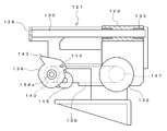
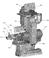
- FIG. 27 shows a dispensing device according to the third embodiment. Since this dispensing apparatus basically has the same configuration as that according to the first embodiment, the description of the same configuration is omitted, and the difference will be described below.
- the apparatus main body 161 has a detachable space 163 for allowing the chemical solution bottle 2 to be attached and detached, and a patient bottle 6 on the lower side of the display 162, and dispensing for dispensing the chemical solution in the chemical solution bottle 2.
- the detachable space 163 can be opened and closed by a shutter 165 provided so as to be slidable in the horizontal direction along the front and right sides of the apparatus main body 161.
- the shutter 165 can open not only the front side but also the side area. Therefore, the attaching / detaching operation of the chemical liquid bottle 2, the internal cleaning, the maintenance, and the like can be easily performed.
- a bottle support 166 is provided as shown in FIG.
- the bottle support portion 166 has a configuration in which a plurality of rotation support portions 168 are provided on an annular support body 167 provided in the apparatus main body 161.
- a mechanism for rotating the chemical liquid bottle 2 supported by the rotation support unit 168 (a rotation driving unit 185 described later) and a mechanism for discharging the chemical liquid from the chemical liquid bottle 2 to the patient bottle 6 (described later).
- the moving member 253, the second pressing member 254, etc.) are disposed in the vicinity of the annular support 167, and a wide space can be secured on the lower side. For this reason, it is possible to make the above-mentioned attachment / detachment space 163 and dispensing space 164 sufficiently wide.
- annular support 167 Although the details of the annular support 167 are not shown, an annular guide portion protruding in a substantially triangular cross section is formed on the outer peripheral portion.
- the annular support 167 is supported at four locations of the annular guide portion by a support roller having a substantially V-shaped groove formed on the outer peripheral surface thereof, and can be rotated by driving a motor.
- the annular support 167 is provided with rotation support portions 168 at equal intervals in a plurality of locations in the circumferential direction, and the chemical bottle 2 is supported on each rotation support portion 168 (in FIG. 28, the rotation support portion 168). And only two of the chemical bottles 2 are shown).
- the rotation support unit 168 includes a support base 169 and a rotation part 171 that is connected to the support base 169 so as to be rotatable about a support shaft 170.
- the support base 169 includes a support main body 172 having a bifurcated lower end side, and a groove 173 in the support main body 172 (when attached to the annular support 167, the outer diameter of the annular support 167 Side wall part 174 formed on the side) and an attachment part 175 extending from the upper end of the support body 172.
- a through-hole 172a (the side wall portion side is not shown) is formed in the support main body 172 and the side wall portion 174, and a support shaft 170 is inserted therethrough as shown in FIG.
- a driven gear 176 in which a region where a gear is formed is limited by cutting a part of the outer peripheral surface is fixed to one end portion of the support shaft 170.
- a circular opening (not shown) is formed in the side wall part 174, and a rod 208 of a lock mechanism 186 described later can be projected and retracted in the groove part 173 through the opening.
- the rotating portion 171 is obtained by fixing a pair of arm portions 179 a and 179 b via a spacer 178 to a rotating plate 177 that is provided on the support base 169 so as to be rotatable about a support shaft 170.
- Rotating plate 177 has a configuration in which both side walls 181a and 181b are arranged opposite to each other on both sides of intermediate wall 180 and one end thereof is covered with ceiling wall 182. The other end portions of the side walls 181a and 181b further extend from the intermediate wall 180, and the extended portion is rotatably supported by a support shaft 170 provided on the support base 169.
- One side wall 181a is formed with an opening (not shown) through which a rod 208 of a lock mechanism 186 described later is inserted.
- a substantially U-shaped guide portion 183 is formed by the spacer 178 and the both arm portions 179a and 179b, and the stopper 219 attached to the chemical liquid bottle 2 is detachable.
- One arm portion 179b is formed with a rectangular locking hole 184, and a locking claw 233 provided on the plug 219 can be engaged and disengaged. Accordingly, the chemical liquid bottle 2 can be held by the both arm portions 179a and 179b via the plug body 219, that is, the plug body member 218.
- the chemical solution bottle 2 can be held by the arm portion 179 protruding from the rotation plate 177 of the rotation support portion 168 to the inside of the annular support body 167. Therefore, when the rotation support part 168 is rotated, the chemical bottle 2 moves from the attachment / detachment preparation position on the upper inner side of the annular support 167 to the attachment / detachment position in the attachment / detachment space 163 on the lower outer side. That is, the attachment / detachment position can be set to a position where it is easy to work from the outside of the apparatus main body 161.
- the liquid chemical bottles 2 supported by the respective rotation support portions 168 by the rotation of the annular support 167 are transported by a predetermined pitch in the circumferential direction, and the transport positions include an attaching / detaching preparation position of the chemical liquid bottle 2 and a dispensing position. It is.
- a rotation drive unit 185 and a lock mechanism 186 are arranged.
- the rotation drive unit 185 includes a rotation drive main body 187, a first motor unit 188 that can be moved up and down on the rotation drive main body 187, and the first motor unit 188. And a second motor unit 189 that moves up and down, and is positioned below the rotation support unit 168.
- the rotation drive main body 187 includes a bottom plate 190 having a rectangular shape in plan view, and guide frames 191 provided at both ends thereof. A region surrounded by the guide frame 191 and the bottom plate 190 is provided with a pair of guide shafts 192 (one not shown) at a predetermined interval in the width direction. And the raising / lowering block 193 is each provided so that raising / lowering along the guide shaft 192 is possible.
- the first motor unit 188 includes a cover body 197 including a front plate 194, both side plates 195, and a top plate 196.
- the first motor 198 is fixed to the back of the front plate 194, and the first motor 188 is disposed on the front of the front plate 194.
- a drive gear 199 and an intermediate gear 200 are provided.
- the first drive gear 199 is attached to the rotation shaft of the first motor 198 that passes through the front plate 194 and protrudes to the front side. Further, the intermediate gear 200 is rotatable around the shaft portion and meshes with the first drive gear 199. Accordingly, when the first motor 198 is driven to rotate in the forward and reverse directions, the intermediate gear 200 rotates in the forward and reverse directions via the first drive gear 199.
- the second motor unit 189 meshes with the second motor 201 fixed to the bottom plate 190 of the rotation drive main body 187 and the second drive gear 202 provided on the rotation shaft of the second motor 201, and the one lifting block 193 is engaged. And a rack portion 203 fixed to the rack.
- the lifting block 193 moves up and down along the guide shaft 192 from the second driving gear 202 via the rack portion 203.
- the elevating block 193 is moved upward, the intermediate gear 200 is raised accordingly, and the intermediate gear 200 meshes with the driven gear 176 of the support base 169.
- the lock mechanism 186 is for restricting the position of the rotating portion 171 with respect to the support base 169, as shown in FIGS.
- the lock mechanism 186 positions the rotating portion 171 with respect to the support base 169 and maintains the chemical bottle 2 in an upside down state, and an operation member for operating the lock member 204. 205.
- the lock member 204 is attached to each rotation support portion 168, and the operation member 205 is disposed in the vicinity of the attachment / detachment preparation position.
- the lock member 204 includes a lock main body 206 that is screwed and fixed to the side wall 174 of the support base 169, and a rod portion 207 that is slidably held by the lock main body 206.
- the lock body 206 is formed in a rectangular frame shape.
- the rod portion 207 is obtained by connecting a pair of upper and lower rods 208 with two right and left connecting rods (a first connecting rod 209a close to the support base 169 and a second connecting rod 209b far away). Each rod 208 is slidably disposed on an upper part and a lower part of the lock body 206.
- the connecting rod 209 is disposed in the opening portion so as to be movable in the left-right direction through the elongated holes in the upper portion and the lower portion that open to the opening portion 206a of the lock body 206.
- the actuating member 205 includes an actuating body 210, an actuating bar 211 that can be moved in and out of the actuating body 210, and an actuating motor 212 for reciprocating the actuating bar 211.
- the operation main body 210 has a thin, substantially rectangular parallelepiped shape, and a communication hole communicating with the upper and lower surfaces is formed at a position slightly shifted from the center to one side edge.
- a communication hole communicating with the upper and lower surfaces is formed at a position slightly shifted from the center to one side edge.
- an opening that also opens at a part of the inner peripheral surface constituting the communication hole is formed on the upper surface of the operation main body 210.
- elongated holes are respectively formed at three locations along the side edge portion.
- Three magnetic sensors 213 are attached to each slot.
- the actuating bar 211 is rod-shaped, and on one end side, a substantially triangular first protrusion 214 and a second protrusion 215 are formed on the left and right sides at two positions in the longitudinal direction.
- a permanent magnet (not shown) is provided on the upper surface of the other end side of the operation bar 211. The permanent magnet is detected by each magnetic sensor 213 so that it can be determined whether the operation bar 211 is located at the reference position, the first protruding position, or the second protruding position.
- the actuating bar 211 is in the first projecting position, and the first projecting portion 214 presses the first connecting rod 209a, and the rod 208 projects to the support base 169 side to the opening formed in the side wall 181a of the rotating plate 177.
- Positioning restricts the position of the rotation plate 177 (the rotation part 171) with respect to the support base 169 (locked state). Further, the operating bar 211 is the second projecting position, the second projecting portion 215 presses the second connecting rod 209b, and the rod 208 is retracted from the support base 169 side to make the pivot plate 177 pivotable ( Unlocked).
- a rack gear (not shown) is formed on one side surface of the operation bar 211.
- the driving motor 212 has a drive gear 216 integrated with a rotating shaft, and is fixed to the operating body 210 via a mounting plate 217. In this fixed state, the drive gear 216 is positioned in the communication hole of the operation main body 210 and functions as a pinion that meshes with the rack gear of the operation bar 211 through the opening.
- the operating motor 212 is driven to rotate forward and backward in accordance with a control signal from the control device based on the detection signal from each magnetic sensor 213.
- a plug member 218 is attached to the upper opening of the chemical liquid bottle 2. 36 to 38, the plug body member 218 is a flexible material connected to one of a plug body 219 and a pair of through holes (not shown) penetrating the plug body 219.
- the first tube 221 functions as the chemical liquid dispensing nozzle of the present invention.
- the stopper 219 has a substantially rectangular parallelepiped shape, and a concave portion 224 having a circular shape in a plan view in which the mouth portion of the chemical liquid bottle 2 can be arranged is formed on the mounting surface.
- a female screw (not shown) is formed on the inner peripheral surface of the recess 224, and a male screw formed at the mouth of the medicine bottle 2 can be screwed together.
- a pair of through holes are formed in the bottom surface of the recess 224.
- An air nozzle 220 is connected to one of the through holes, and air is supplied into the chemical liquid bottle 2 through the air nozzle 220.
- the other through-hole is for discharging the chemical solution from the chemical solution bottle 2 and is connected to the first tube 221.
- an RFID 225 (Radio Frequency ⁇ ⁇ IDentification) is built in the mounting surface in the vicinity of the recess 224.
- the RFID 225 stores a specific ID (IDentification: hereinafter referred to as an attachment position ID) for identifying which rotation support unit 168 is the rotation support unit 168.
- the mounting position ID stored in the RFID 225 is written by an RFID reader / writer (not shown).
- a protrusion 226 is formed on the upper end of the side surface of the stopper 219, and a bottle stopper 227 is slidably attached thereto.
- the bottle fastener 227 is formed by molding a synthetic resin material into a substantially U shape, and includes a side wall portion 228 that surrounds the three surrounding sides and a U-shaped presser portion 229 that bulges inward from the inner edge portion. Yes.
- a groove 230 is formed at the lower end of the facing surface of the side wall 228, and the protrusion 226 of the plug 219 is located.
- the holding portion 229 is engaged with the annular bulging portion 2a of the chemical liquid bottle 2 simply by sliding the bottle stopper 227. Stop.
- the chemical bottle 2 is not screwed to the concave portion 224 of the stopper 219 to an appropriate position, the bottle fastener 227 cannot be properly locked to the annular bulging portion 2a of the chemical bottle 2, and the screw bottle 2 is screwed. It is understood that the state is insufficient.
- a latch member 231 is provided in the plug body 219.
- the latch member 231 immerses the locking claw 233 protruding from one side surface by pressing the pressing portion 232 protruding from one end side.
- the pushing portion 232 of the latch member 231 protrudes from one end surface of the plug body 219 so as to be pushed in, and the locking claw 233 protrudes from one side surface of the plug body 219 so as to be retractable.
- the locking claw 233 is engaged with and disengaged from a locking hole 184 formed in one arm portion 179 b of the rotating portion 171 so that the plug 219 can be attached to the rotating portion 171 of the rotating support portion 168.
- a communication hole (not shown) is opened on the bottom surface of the plug 219.
- the first tube connector 234 is connected to one through hole, and one end of the first tube 221 is connected to the first tube connector 234.
- a second tube connector 235 is connected to the other through hole, and an opening on one end side of the second tube 236 is further connected thereto.
- a third tube connector 237 is connected to the communication hole, and the other end side opening of the second tube 236 is connected to the communication hole.
- the communication hole extends to one end surface of the plug 219, and a conical guide recess 238 is formed at the opening position.
- a pressure receiving piece 239 attached so as to be rotatable about the shaft portion 239a is provided.
- One end portion of the pressure receiving piece 239 protrudes obliquely from the plug body 219 to the side, and the other end portion presses the second tube 236 against the substantially U-shaped guide receiving portion 240 fixed to the bottom surface of the plug body 219. Yes.
- the pressure receiving piece 239 rotates when a pressing plate 269 (described later) is pressed against one end of the pressure receiving piece 239 to release the closed state of the second tube 236 and open the flow path.
- the air nozzle 220 is connected to one through hole formed in the concave portion 224 of the stopper 219 and extends into the chemical liquid bottle 2, and its tip is located near the bottom surface of the chemical liquid bottle 2.
- the guide member 222 is provided with a first guide portion 241 and a second guide portion 242 on a support plate 222 a fixed to the bottom surface of the plug 219.
- the first guide portion 241 is fixed to one side surface of the support plate 222a, and has a curved surface 243 that gradually protrudes forward as the end surface on the protruding side moves downward.
- the front end portion of the curved surface 243 is cut away leaving both side portions to form a groove-shaped portion 244, and the bottom surface thereof is constituted by a flat pressure receiving surface 245.
- the first guide part 241 includes a first link plate 246, a second link plate 247, and a first pressing member 223 attached to the other side surface of the support plate 167.
- the first link plate 246 is attached to the support plate 222a so as to be rotatable about the support shaft 246a.
- the first link plate 246 has a press receiving portion 248 formed by extending one end portion thereof in a right angle direction.
- a pressing roller 273 integrated with the cam 271 is pressed against the pressing receiving portion 248, and the first link plate 246 rotates.
- the second link plate 247 is attached to the support plate 222a so as to be rotatable about the support shaft 247a.
- a first pressure receiving roller 249a is rotatably provided on one surface of the second link plate 247, and a second pressure receiving roller 249b is rotatably provided on the other surface.
- the second link plate 247 is biased by a spring 250 (not locked in FIG. 36), and the second pressure receiving roller 249b is pressed by a pressing portion 274 formed on the cam 271 of the second pressing member 254. As a result, it rotates counterclockwise in FIG. 36 about the support shaft 247a against the urging force of the spring 250.
- the first pressing member 223 is fixed to the second link plate 247.
- the first pressing member 223 includes a pressing protrusion 251 whose one end bulges in a semicircular cross section.
- the pressing protrusion 251 of the first pressing member 223 enters the groove-shaped portion 244 of the first guide portion 241.
- the pressing protrusion 251 approaches the pressing receiving surface 245, the first tube 221 disposed there is crushed and elastically deformed, and the flow path is closed.
- the second link plate 247 rotates when the first pressing receiving roller 249a is pressed by the pressing portion 274 formed on the cam 271 of the second pressing member 254, and the second link plate 247 is rotated by the pressing protrusion 251.
- the pressed state of the first tube 221 is released to open the flow path.
- the second guide part 242 is fixed to the support plate 222a, and a through hole (not sushi) is formed on the free end side.
- a fourth tube connector 252 is connected to the through hole, and the first tube 221 is connected to the fourth tube connector 252.
- the second pressing member 254 for adjusting the outflow amount of the chemical liquid that is moved by the moving member 253 and poured out from the chemical liquid bottle 2 can be disposed at the extraction position.
- the moving member 253 includes a slide base 256 that can be moved forward and backward by driving a slide motor 255.
- a rack 257 is formed on the side of the slide table 256, and a pinion (not shown) provided on the rotation shaft of the slide motor 255 is engaged with the rack 257.
- the movement of the slide base 256 is detected by the slide position detection sensor 258, and the second pressing member 254 can be positioned at the forward position and the backward position, respectively.
- a holding block 259 for holding the slide motor 255 is provided above the slide table 256.
- an air supply pipe 260 and a nozzle portion 261 connected thereto are provided on the upper side of the holding block 259.
- the air supply pipe 260 is connected to an air supply source 262 and ejects air supplied therefrom from the nozzle portion 261.
- the nozzle portion 261 is inserted into a guide recess 238 formed on the end surface of the plug 219 and connected to a communication hole (not shown). Therefore, the ejected air is supplied from the air nozzle 220 into the chemical liquid bottle 2 through the communication hole.
- a compressor is used for the air supply source 262, and in the middle of the path to the nozzle portion 261, four sets of a switch valve 263 and a needle valve 264 connected in series from the air supply source side are connected in parallel, and beyond that An open / close valve 265 and a pressure sensor 266 are connected. Any one of the four switch valves 263 is opened, and air can flow only in one flow path.
- the needle valve 264 has different flow rates per unit time that can be passed. Then, by opening any one of the switch valves 263, the amount of air supplied into the chemical liquid bottle 2 can be adjusted.
- the opening / closing valve 265 and the pressure sensor 266 are not necessarily required.
- the substrate 268 and the pressing plate 269 are fixed to the holding block 259 via the holding plate 267.
- the pressing plate 269 presses and rotates one end of the pressing receiving piece 239 when the slide base 256 is advanced. And when the press receiving piece 239 rotates, the 2nd tube 236 arrange
- the second pressing member 254 is attached above the slide base 256.
- the second pressing member 254 includes a cam 271 provided on the rotation shaft of the rotation motor 270.
- a pressing protrusion 272 is formed on one surface of the cam 271. Then, when the rotation motor 270 is driven to rotate in the forward direction to rotate the cam 271 in the forward direction, the pressing protrusion 272 comes into contact with the lower edge 261a of the first link plate 246, and the first link plate 246 is moved (in FIG. 36, Rotate clockwise about the spindle 246a.
- a rotatable pressing roller 273 is provided on the other surface of the cam 271. Then, when the rotating motor 270 is driven in reverse to reversely rotate the cam 271, the pressing roller 273 comes into pressure contact with the first tube 221. Then, by rolling while changing the pressure contact position, the chemical solution in the first tube 221 is sent out by a predetermined amount. At this time, the pressing protrusion 272 contacts the upper edge 261b of the first link plate 246 and rotates the first link plate 246 (in the counterclockwise direction around the support shaft 246a in FIG. 36). The first link plate 246 has no influence on other members.
- a pressing portion 274 that protrudes partially is formed on the outer peripheral portion of the cam 271.
- the pressing portion 274 is in pressure contact with the second pressing receiving roller 249 b of the second link plate 247 and rotates the second link plate 247. Then, by rotating the first pressing member 223 integrated with the second link plate 247, the pressing of the first tube 221 by the pressing protrusion 251 is temporarily released.
- the cam 271 provided on the second pressing member 254, the link plates 246, 247, etc. function as interlocking members according to the present invention, and operate in conjunction with the first pressing member 223 and the second pressing member 254. It can be made to.
- the first pressing member 223, the second pressing member 254, and the like constitute a chemical solution discharging mechanism.
- the plug member 218 is attached to the mouth of the chemical liquid bottle 2. That is, the air nozzle 220 is inserted from the mouth portion of the chemical liquid bottle 2 and covered with the plug body 219, and the mouth portion is disposed in the recess 224 of the plug body 219. Then, the bottle stopper 227 is slid, and the stopper member 218 is fixed to the chemical liquid bottle 2 by the pressing portion 229. As described above, the plug member 218 can be easily attached to the chemical liquid bottle 2 simply by inserting the air nozzle 220 into the chemical liquid bottle 2, covering the mouth portion with the stopper 219, and sliding the bottle stopper 227. be able to.
- the barcode attached to the outer peripheral surface of the chemical bottle 2 is read with a barcode reader.
- the data stored in the storage unit 89 is referred to, and information related to the corresponding drug (name of drug, code number, etc .; hereinafter referred to as drug solution information) is called and written in the RFID 225.
- the shutter 165 is slid to expose the attachment / detachment space 163.
- the shutter 165 it is possible to secure a wide area that opens not only on the front side of the apparatus main body 161 but also on the side side, and that allows easy access to the attachment / detachment space 163.
- This is only when the chemical bottle 2 supported by the rotation support portion 168, the lock mechanism 186, the moving member 253, the second pressing member 254, etc. are arranged above the annular support 167 and the chemical bottle 2 is replaced.
- the rotation support portion 168 is rotated to move the chemical liquid bottle 2 to the attachment / detachment space 163 below the annular support 167. Therefore, in addition to the attaching / detaching operation of the chemical liquid bottle 2 described below, cleaning of the attaching / detaching space 163, other maintenance, and the like can be performed smoothly.
- medical solution bottle 2 is each mounted
- the lock member 204 is operated to bring the rotating portion 171 into the unlocked state, and then the rotating drive portion 185 is moved (the second motor portion 189 is driven to move the first motor portion 188).
- the intermediate gear 200 of the rotation drive unit 185 is engaged with the driven gear 176 of the rotation support unit 168.
- the first drive gear 199 is rotated and the driven gear 176 is rotated via the intermediate gear 200.
- the rotation part 171 of the rotation support part 168 rotates from the attachment / detachment preparation position to the attachment / detachment position.
- the storage unit 89 stores the chemical information stored in the chemical bottle 2 to be attached and the attachment position ID of the rotation support unit 168 of the rotation unit 171 located at the attachment / detachment position.
- the data table of the storage unit 89 is inquired, and the chemical solution bottle 2 in which the corresponding chemical solution is stored is specified from the associated mounting position ID. And the corresponding chemical
- position information that associates the rotation position with the positional relationship of the chemical liquid bottle 2 supported by each rotation support portion 168 is stored, and the annular support 167 is rotated based on the position information. What should I do? Further, an RFID reader / writer may be provided at the extraction position and the RFID 225 may be read to identify the position of the rotation support 167.
- the bottle placing portion 60 on which the patient bottle 6 is placed is raised, and the upper opening thereof is positioned in the vicinity of the fourth tube connector 252. Further, by driving the slide motor 255, the slide base 256 is advanced, and the second pressing member 254 is positioned at a predetermined position with respect to the rotation support portion 168. At this time, the rotation shaft of the rotation motor 270 provided on the second pressing member side is positioned in the positioning recess 224 formed in the spacer 178 on the rotation support portion side. Further, the air nozzle 220 enters the guide recess 238 of the plug 219 and is connected to the communication hole 234. Further, the pressing plate 269 presses the pressure receiving piece 239 and rotates it to release the second tube 236 from the crushed state.
- the rotation motor 270 is driven to rotate in the reverse direction, the cam 271 is rotated in the reverse direction, and the pressure receiving portion 248 is pressed by the pressing roller 273, thereby rotating the first link plate 246.
- the pressure receiving roller 249 is pressed by the lower edge of the first link plate 246 to rotate the second link plate 247, and the first pressing member 223 integrated with the second link plate 247 becomes the first tube 221.
- the chemical solution in the chemical solution bottle 2 is continuously supplied to the patient bottle 6 via the first tube 221.
- the supply amount of the chemical solution to the patient bottle 6 is performed based on the weight detected by the bottle mounting unit 60 until the first set value before reaching the desired supply amount (dispensing value).
- the supply of air into the chemical liquid bottle 2 may be performed so that the inside of the chemical bottle 2 is maintained at a constant pressure based on a detection signal from the pressure sensor 266 or the like.
- the internal pressure may be gradually increased so that the discharge amount does not decrease with the decrease.
- the rotation motor 270 is driven to rotate forward, and the cam 271 is rotated forward.
- the second link plate 247 is returned to its original position by the urging force of the spring 250, and the first tube 221 is once pressed by the first pressing member 223 to block the flow path.
- the pressing roller 273 integrated therewith rotates and rolls while pressing against the first tube 221 from the upper side toward the lower side.
- the chemical liquid that has remained in the first tube 221 on the lower side of the position pressed by the pressing roller 273 is pumped downstream.
- the pressing portion 274 formed on the cam 271 contacts the pressing receiving roller 249 of the second link plate 247 to rotate the first link plate 246.
- the first pressing member 223 is temporarily separated from the first tube 221, and a certain amount of the liquid medicine thus pumped flows down to the patient bottle 6 via the fourth tube connector 252.
- the cam 271 continues to rotate in the forward direction until reaching the second set value that is closer to the dispense value than the first set value, and the drug solution is dispensed into the patient bottle by a certain amount. If the detected value becomes the second set value, the rotation speed is suppressed by reducing the voltage applied to the rotation motor 270. This is to eliminate variations in detection values caused by dispensing the drug solution into the patient bottle at a relatively high speed even intermittently. In a state where the detection value is stable, a certain amount of chemical solution is supplied, and when the dispensing value is reached, the driving of the rotation motor 270 is stopped.
- air is supplied in the middle of the chemical liquid flow path from the chemical liquid bottle 2 to the discharge port of the first tube 221 to block the flow of the chemical liquid. Also good. That is, as shown in FIG. 42, an air supply path communicating with the air nozzle 220 is formed in the vicinity of the lower end opening (discharge port) of the air nozzle 220. Then, when the liquid injection operation is completed, air is supplied into the air nozzle 220 through the air supply path. This air is, for example, air after being cleaned or inert gas. As a result, the chemical solution does not directly touch the surrounding atmosphere, and contamination is prevented.
- the stopper 219 is preferably provided with an auxiliary guide part 275 that guides the body part and the bottom part of the chemical liquid bottle 2 in a rotatable manner.
- the auxiliary guide portion 275 is provided on the stopper 219 so as to be rotatable about the shaft portion, and has a lattice-shaped side surface portion 276 that guides a part of the outer peripheral surface of the chemical liquid bottle 2 and a bottom surface that guides about half of the bottom surface. Part 277.
- the auxiliary guide portion 275 is not screwed to the concave portion 224 of the stopper 219 to an appropriate position, similarly to the bottle fastener 227.
- the bottom surface portion 277 cannot rotate to a position where it guides the bottom surface of the chemical liquid bottle 2. Therefore, it is possible to detect whether or not the screwing state of the chemical liquid bottle 2 is appropriate also by the auxiliary guide portion 275.
- the dispensing device may have the following configuration.
- a bottle support part rotatably supported in an annular region, the drug solution dispensing part closing a mouth part of the drug solution bottle, and penetrating the closed part on the bottom side of the drug solution bottle It has an air supply nozzle that extends, and a chemical liquid dispensing nozzle that passes through the closing portion and opens to the mouth of the chemical liquid bottle.
- the bottle support part supports the chemical liquid bottle upside down so that the mouth part is on the lower side when the chemical liquid is dispensed.
- the chemical liquid dispensing nozzle is constituted by a flexible tube extending from the chemical liquid bottle, and by contacting and separating from the tube extending from the chemical liquid bottle moved to the extraction position of the annular region, It is preferable to further include a chemical solution discharge mechanism for pouring the chemical solution in the chemical solution bottle into the patient bottle.
- the chemical solution discharge mechanism includes a first pressing member that crushes the tube and closes the flow path, and the tube toward the pressing position from the upstream side in the flow direction of the chemical solution rather than the pressing position by the first pressing member.
- the air supply unit may further include an air supply unit that forcibly supplies air to the air supply nozzle and promotes the extraction of the chemical liquid from the chemical liquid extraction nozzle by increasing the air pressure in the chemical liquid bottle. preferable. With this configuration, the air pressure in the chemical liquid bottle can be freely adjusted by the air supply unit.
- medical solution extraction part can be attached or detached to the said bottle support part.
- the drug solution dispensing part is a plug member attached to the mouth part of the drug solution bottle, and the stopper member is locked to the bulging part formed in the mouth part by sliding.
- the bottle fastener which supports the said chemical
- the bottle fastener is slidable so as to be engaged with a bulging portion formed in the mouth portion in a state where the chemical liquid bottle is disposed at an appropriate position with respect to the plug member.
- the mouth portion of the chemical liquid bottle is formed with a male screw at a tip portion than the bulging portion, and the chemical liquid dispensing portion is formed with a female screw into which the mouth portion of the chemical liquid bottle is screwed. . With this configuration, it is possible to further strengthen the state of attachment of the chemical liquid dispensing portion to the chemical liquid bottle.
- a dispensing device for dispensing a chemical solution from a bottle to a patient bottle wherein a cleaning water supply unit supplies cleaning water to a nozzle extending from the chemical solution bottle moved to the cleaning position of the annular region, and drying the annular region And an air supply unit that supplies air to the nozzle that has moved to a position.
- the washing water supply unit is disposed below the annular region.
- the said air supply part is arrange
- a dispensing device for dispensing a liquid medicine from a bottle to a patient bottle comprising a diluent tank containing a diluent, and provided with a rotating arm that movably supports an injection tube extending from the diluent tank, The injection port of the injection tube is positioned at an injection position between the patient bottle located at the dispensing position and the drug solution bottle positioned above the patient bottle, and at a separated position away from the patient bottle.
- the pivot arm can be pivoted. With this configuration, even when the drug solution poured into the patient bottle is diluted, it can be easily handled by adding a diluent tank or the like without changing other configurations.
- a storage unit is further provided, and the control unit includes a positional information stored in the detected unit when the chemical bottle is attached to the bottle support unit, and a chemical liquid dispensing unit having the detected unit. It is preferable to store the chemical information stored in the chemical liquid bottle to be attached in the storage means in association with each other.
- a bottle mounting unit on which a bottle is mounted and which can be moved up and down, a bottle detection unit capable of specifying the position of the mouth of a patient bottle mounted on the bottle mounting unit, and the bottle detection unit are detected.
- a control means for adjusting the position of the patient bottle relative to the drug solution dispensing part by moving the bottle placing part up and down based on positional information of the mouth part of the patient bottle.
- the position of the mouth can be specified by the bottle detection unit, and the patient bottle can be automatically moved up and down to a position where it can be dispensed from the drug solution dispensing unit. it can.
- the chemical liquid dispensed from the chemical liquid dispensing unit is less likely to spill.
- the bottle placement unit includes a weight detection unit that can detect the weight of the patient bottle to be placed, including the chemical solution to be filled, and the control means is detected by the weight detection unit.
- the amount dispensed by the liquid medicine dispensing unit Based on the weight of the patient bottle, it is preferable to control the amount dispensed by the liquid medicine dispensing unit. With this configuration, the amount of the chemical solution supplied to the patient bottle can be detected by the weight detection unit, and the amount dispensed can be set to an appropriate value.
- the chemical solution is dispensed from the chemical solution bottle moved to the extraction position of the annular region to the patient bottle, the first dispensing process of dispensing the chemical solution by the first dispensing amount per unit time and the chemical solution before the unit time It is preferable to further comprise control means for executing a second dispensing process for dispensing each second dispensing amount that is smaller than the first dispensing amount.
- the drug solution is poured into the patient bottle in two stages, ie, the first and second dispensing processes.
- One of the dispensing processes is preferably performed by opening and closing a flow path from the drug solution bottle to the patient bottle.
- One end opening is connected to the mouth of the drug solution bottle and extends downward, and a flexible tube capable of supplying the drug solution into the patient bottle through the other end opening, and the tube is pressed and deformed.
- the first pressing member that can move to the closed position that blocks the flow of the chemical liquid that passes through, the open position that releases the pressure on the tube and allows the flow of the chemical liquid, and the pressing position by the first pressing member By pressing and deforming the tube on the upstream side, the closed position that can move downstream while maintaining the state of blocking the flow of the chemical solution that passes through, and the pressure on the tube are released to release the chemical solution.
- a second pressing member movable to an open position allowing flow, and the control means positions the first pressing member and the second pressing member at the open position as the first dispensing process. Maximum dispensing process It is preferable to the execution.
- the chemical solution can be quickly dispensed until immediately before the dispensing process is completed, and the efficient dispensing process can be executed.
- One of the dispensing processes is preferably performed by moving the pressing position of the flow path from the drug solution bottle to the patient bottle toward the downstream side in the flow direction of the drug solution. With this configuration, it is possible to dispense a certain amount of the chemical solution by moving the pressing position of the tube.
- One end opening is connected to the mouth of the drug solution bottle and extends downward, and a flexible tube capable of supplying the drug solution into the patient bottle through the other end opening, and the tube is pressed and deformed.
- the first pressing member that can move to the closed position that blocks the flow of the chemical liquid that passes through, the open position that releases the pressure on the tube and allows the flow of the chemical liquid, and the pressing position by the first pressing member By pressing and deforming the tube on the upstream side, the closed position that can move downstream while maintaining the state of blocking the flow of the chemical solution that passes through, and the pressure on the tube are released to release the chemical solution.
- a second pressing member movable to an open position allowing flow, and the control means positions the first pressing member and the second pressing member at the closed position as the second dispensing process.
- the first pressing member located in the closed position and the first pressing member are moved to the downstream side while moving the first pressing member to the open position and maintaining the state of blocking the flow of the chemical liquid passing through the second pressing member. It is preferable to execute a small amount dispensing process in which a small amount of dispensing is performed an arbitrary number of times so that the drug solution stored in the tube partitioned by the two pressing members can be supplied to the patient bottle.
- a closing part that closes the mouth part, an air supply nozzle that extends through the closed part to the bottom surface side of the chemical liquid bottle
- an air supply unit that forcibly supplies air to the air supply nozzle and promotes the extraction of the chemical solution from the chemical solution extraction nozzle by increasing the air pressure in the chemical solution bottle.
- Pressure detecting means for directly or indirectly detecting the air pressure in the chemical liquid bottle is further provided, and the control means controls the amount of air supplied by the air supply unit based on the detection result of the pressure detecting means.
- the control means may control the air supply amount by the air supply unit based on the detection result of the pressure detection means so that the air pressure in the chemical liquid bottle is constant.
- the control means may control the amount of air supplied by the air supply unit based on the detection result of the pressure detection means so that the flow rate per unit time of the chemical liquid dispensed from the chemical liquid bottle is constant. Good.
- the control unit may control an air supply amount by the air supply unit so that a pressure detected by the pressure detection unit in the second extraction process is smaller than that in the first extraction process.
- the control unit may control an air supply amount by the air supply unit such that the pressure detected by the pressure detection unit increases as the viscosity of the chemical solution stored in the chemical solution bottle increases. It is preferable that the middle of the flow path for supplying air into the chemical bottle is composed of at least two flow paths with different amounts of air that can be supplied per unit time.
- a second pressing member that includes a guide member that includes a guide groove that guides the tube in an arc shape, and that the second pressing member presses the tube by moving along the guide groove to block the flow of the chemical solution. It is preferable to provide a part. With this configuration, it is possible to block the flow of the chemical solution in the tube even while moving the second pressing portion.
- the first pressing member is attached to the guide member so as to be rotatable about a first support shaft, and a first pressing portion capable of pressing the tube, and the tube is pressed by the first pressing portion.
- the second pressing member includes a cam member that operates the first pressing member while maintaining a closed state in which the tube flow path is blocked by the second pressing portion. Is preferred. With this configuration, the chemical liquid stored in the tube can be discharged by operating the first pressing member in a state where the flow of the chemical liquid in the tube is blocked by the second pressing portion.
- the second pressing member is provided so as to be rotatable about a second support shaft, and includes a driving member that drives the second pressing member, and the control means rotates the second pressing member forward by the driving member. It is preferable to drive and execute the small-volume dispensing process.
- a single drive member dispenses a small amount of liquid to the patient bottle every time the tube is stored, and the tube is opened to continuously supply the liquid from the chemical bottle to the patient bottle.
- the maximum dispensing process can be executed, and the configuration can be simplified, downsized, and manufactured at low cost.
- the control means drives the second pressing member by the driving member in the small-quantity dispensing process, and stores the chemical in the tube by the first pressing portion of the first pressing member and the second pressing portion.
- the storage position a small amount dispensing position in which the second pressing portion is moved downstream while maintaining the pressing state, and the tube pressing state by the first pressing portion of the first pressing member is released by the cam member; 2
- the release state of the tube by the pressing portion is released, and the tube is circulated and moved at the preparation position at which the pressing state of the tube by the first pressing portion is resumed.
- the maximum dispensing process is performed by the driving member.
- the pressing member is driven to release the pressing state by the second pressing portion, and the first pressing portion of the first pressing member is separated from the tube by the cam member and maintained in an open state. It may be.
- the second pressing member is provided so as to be rotatable about a second support shaft, and includes a driving member that drives the second pressing member to rotate forward and reverse.
- the control means is configured to be driven by the driving member.
- the small amount dispensing position where the tube is pressed by the first pressing portion of the first pressing member by the cam member and the tube pressing state by the second pressing portion are released, and the first pressing portion
- the first pressing portion of the may be performed a maximum dispensing process of maintaining the open state is separated from the tube.
- the tube can be fully opened until a desired dispensing amount is reached, and then a certain amount of the chemical solution stored in the tube can be supplied. That is, by finely adjusting the amount of the chemical solution supplied to the patient bottle immediately before reaching the desired dispensing amount, accurate dispensing can be performed while simplifying the configuration and manufacturing at low cost.
- a flexible tube that has one end opening connected to the mouth of the drug solution bottle and extends downward and can supply the drug solution into the patient bottle through the other end opening, and a guide for guiding the tube in an arc shape
- the closed position that can move downstream while maintaining the state of blocking the flow of the chemical liquid that passes through, and the pressure on the tube are released.
- a pressing member having a pair of pressing portions movable to an open position allowing the flow of the chemical solution, and the control means deforms by pressing the tubes with the pair of pressing portions as the second dispensing process.
- a rotation drive unit and the bottle support unit supports the drug solution bottles upside down in the annular region so that the mouth part of the drug solution bottle is located on the lower side, and the rotation drive unit
- the liquid bottle rotated by the rotation drive unit is positioned below the advance position so that the bottle support unit can be moved to an advance position where the bottle support section can be operated and a retracted position separated from the bottle support section. It also has a removable space It is. With this configuration, the attachment / detachment space can be made sufficiently wide, and the attachment / detachment operation of the chemical solution bottle can be performed smoothly.
- the plurality of chemical liquid bottles arranged in the annular region on substantially the same circumference support the plurality of chemical liquid bottles so as to move along the circumferential direction of the annular region, and move to the extraction position of the annular region.
- a rotation drive unit that moves the bottle, and the bottle support unit supports the chemical solution bottles upside down so that the mouth portion of the chemical solution bottle is positioned on the lower side in the annular region.
- a closing part for closing the mouth of the chemical liquid bottle In the mouth, a closing part for closing the mouth of the chemical liquid bottle, an air supply nozzle extending through the closing part to the bottom surface side of the chemical liquid bottle, and penetrating the closing part to the mouth of the chemical liquid bottle
- An open, flexible tube Equipped with a medicinal solution dispensing part having a medicinal solution dispensing mechanism for dispensing the medicinal solution in the medicinal solution bottle into the patient bottle by contacting and separating from the tube,
- the medicinal solution discharge mechanism can be moved to an advance position where the medicinal solution can be dispensed by being brought into and out of contact with the tube, and a retracted position separated from the dispense position, and a patient bottle is placed below the advance position.
- Handle 22 Waste liquid recovery tank 23 ... Opening / closing door 23a ... Handle 24 ... Storage chamber 25 ... Support plate 26 ... Annular support 27 ... Times Dynamic support portion 28 ... Opening portion 29a ... first guide roller 29b ... second guide roller 30 ... guide roller 31 ... drive gear 31a ... operating portion 32 ... drive motor 33 ... encoder 34a, 34b ... annular plate 35 ... connection rail 36 ... Ring part 37 ... gear part 38 ... support base 39 ... rotating part 39a ... support shaft 40 ... first Nchibarubu 41 ... driving arm 41a ... shaft 42 ... cam 44 ... rotating unit motor 43 ... arm arm body 45 ... bottle mounting portion (closure) 46 ... mouth part 46a ...
- Interlocking gear 70 Elevating position detection sensor 71 ... First elevating motor 71a ... Cam 72 ... Elevating plate 73 ... Pump 73a ... Air nozzle 74 ... Injection tube 75 ... Oscillating support 6 ... Rotating arm 76a ... Support shaft 76b ... Inlet port 77 ... First tube pump 78 ... Rotating motor 78a, 78b ... Gear 79 ... Second pinch valve 80 ... Washing dishes 80a, 80b ... Through hole 81 ... Waste water port 82 ... Wastewater tube 83 ... Cleaning nozzle 84 ... Air supply nozzle 85 ... Vertical movement motor 85a ... Cam 86 ... Second tube pump 87 ... Compressor 87a ...
- Tube 88 ... Control part 89 ... Storage part 90 Server 91 ... Opening / closing cam 91a ... Projection 91b ... outer peripheral surface 92 ... pressing member 92a ... support shaft 93 ... spring 101 ... bottle support part 102 ... support base 103 ... guide member 103a ... through hole 104 ... ceiling part 105 ... side part 106 ... opening part 107 ... bottle mounting part 108 ... Plane part 109 ... Cylinder part 110 ... First flow path connection part 112 ... Tube 113 ... Rotation 113a ... support shaft 114 ... guide groove 115 ... guide piece 116 ... support shaft guide 117 ... first pressing member 117a ... support shaft 118 ...
Abstract
Disclosed is a dispensing device which is configured to include: a bottle supporting unit (3) which supports a plurality of chemical bottles (2) disposed substantially concyclically in an annular region so as to move along the circumferential direction of the annular region and supports the plurality of chemical bottles (2) rotatably toward the inside of the annular region; and a rotation driving unit (4) which stirs the chemicals contained in the chemical bottles (2) by rotating the chemical bottles (2) with the bottle supporting unit (3) being operated; wherein the chemicals are ejected from the chemical bottles (2) which move into the ejection position of the annular region.
Description
本発明は、分注装置に関するものである。
The present invention relates to a dispensing device.
従来、分注装置として、例えば、次のような構成のものが公知である。
すなわち、特許文献1には、平面視環状の載置体に、その周方向に沿って複数の薬液ボトルを載置し、ノズルを介して各薬液ボトルに薬液を注入するようにした分注装置が記載されている。 Conventionally, as a dispensing device, for example, one having the following configuration is known.
That is,Patent Document 1 discloses a dispensing device in which a plurality of chemical liquid bottles are mounted on a circular mounting body in plan view along the circumferential direction, and a chemical liquid is injected into each chemical liquid bottle via a nozzle. Is described.
すなわち、特許文献1には、平面視環状の載置体に、その周方向に沿って複数の薬液ボトルを載置し、ノズルを介して各薬液ボトルに薬液を注入するようにした分注装置が記載されている。 Conventionally, as a dispensing device, for example, one having the following configuration is known.
That is,
ところで、薬液ボトルに収容した薬液が懸濁液である場合、時間の経過に伴って徐々に液体中に分散した固体粒子が不均一となるため、分注する前に攪拌して均一化する必要がある。このため、前記分注装置では、前記ノズルを利用して、薬液ボトル内の薬液を吸引し、吸引した薬液を再び薬液ボトル内に戻すことにより、薬液を攪拌するようにしている。
By the way, when the chemical liquid stored in the chemical liquid bottle is a suspension, the solid particles gradually dispersed in the liquid with time will become non-uniform, so it is necessary to agitate and homogenize before dispensing There is. For this reason, in the dispensing device, the chemical liquid is agitated by sucking the chemical liquid in the chemical liquid bottle using the nozzle and returning the sucked chemical liquid into the chemical liquid bottle again.
しかしながら、前記特許文献1に記載の分注装置では、攪拌を適切に行えるように、薬液ボトルからノズルを介して十分な量の薬液を吸引できるように、別途、貯留室が必要となる。
However, the dispensing device described in Patent Document 1 requires a separate storage chamber so that a sufficient amount of chemical solution can be sucked from the chemical solution bottle through the nozzle so that stirring can be performed appropriately.
また、ノズルを介しての薬液の吸引及び排出を迅速に行うために、使用するポンプを高性能なものとする必要が生じるが、ポンプの大型化、高価格化が避けられないし、ノズルを介しての薬液の吸引及び排出の迅速化には限界がある。
In addition, in order to quickly suck and discharge the chemical solution through the nozzle, it is necessary to make the pump to be used have a high performance. However, an increase in the size and cost of the pump is unavoidable, and the pump cannot be avoided. There is a limit to speeding up the suction and discharge of all chemicals.
本発明は、簡単な構成であるにも拘わらず、薬液ボトル内の薬液を短時間で十分に攪拌することのできる分注装置を提供することを課題とする。
The object of the present invention is to provide a dispensing device that can sufficiently stir the chemical solution in the chemical solution bottle in a short time despite the simple configuration.
本発明は、前記課題を解決するための手段として、
分注装置を、
略同一円周上の環状領域に配置された複数の薬液ボトルが前記環状領域の周方向に沿って移動するように前記複数の薬液ボトルを支持し、前記環状領域の注出位置に移動した薬液ボトルから患者用ボトルに薬液を注出する分注装置であって、
前記複数の薬液ボトルを回動可能に支持するボトル支持部と、
前記ボトル支持部を作動させて前記薬液ボトルを回動させることにより、収容された薬液を攪拌する回動駆動部と、
を備えた構成としたものである。 As a means for solving the above problems, the present invention provides:
Dispensing device
A chemical solution that supports the plurality of chemical solution bottles so that a plurality of chemical solution bottles arranged in an annular region on substantially the same circumference moves along the circumferential direction of the annular region, and moves to a dispensing position of the annular region. A dispensing device for dispensing a drug solution from a bottle to a patient bottle,
A bottle support part for rotatably supporting the plurality of chemical liquid bottles;
A rotation drive unit for agitating the stored chemical solution by operating the bottle support unit to rotate the chemical solution bottle;
It is set as the structure provided with.
この構成により、薬液ボトルを回動させるという簡単な構成であるにも拘わらず、収容された薬液を短時間で十分に攪拌することができる。
This configuration makes it possible to sufficiently agitate the contained chemical solution in a short time despite the simple configuration of rotating the chemical solution bottle.
前記ボトル支持部は、前記複数の薬液ボトルを前記環状領域の内側に向かって回動可能に支持するようにするのが好ましい。
It is preferable that the bottle support portion supports the plurality of chemical liquid bottles so as to be rotatable toward the inside of the annular region.
この構成により、薬液ボトルが配置される環状領域の内側のデッドスペースを薬液ボトルの回動に利用することができ、複数の薬液ボトルを備えた構成であるにも拘わらず、分注装置の小型化を実現することが可能となる。
With this configuration, the dead space inside the annular region in which the chemical liquid bottle is arranged can be used for the rotation of the chemical liquid bottle, and the small size of the dispensing device despite the configuration including a plurality of chemical liquid bottles. Can be realized.
前記ボトル支持部は、支持した薬液ボトルを水平位置から、液面位置が薬液ボトルの底面の中心位置を超える第1傾斜位置と、水平面に対して第1傾斜位置と対称な第2傾斜位置との間の回動範囲内で揺動するのが好ましい。
The bottle support section includes a first inclined position where the liquid bottle position is higher than a center position of the bottom surface of the chemical liquid bottle from a horizontal position, and a second inclined position symmetrical to the first inclined position with respect to the horizontal plane. It is preferable to oscillate within the rotation range.
この構成により、短時間で薬液ボトル内の薬液を攪拌することができ、作業性を向上させることが可能となる。
With this configuration, the chemical solution in the chemical solution bottle can be agitated in a short time, and the workability can be improved.
前記ボトル支持部は、複数の回動支持部を備え、
前記各回動支持部は、前記薬液ボトルをそれぞれ回動可能に支持し、
前記回動駆動部は、前記環状領域の所定位置に移動した前記回動支持部を介して薬液ボトルを回動させるのが好ましい。 The bottle support portion includes a plurality of rotation support portions,
Each said rotation support part supports the said chemical | medical solution bottle so that rotation is possible respectively,
It is preferable that the rotation driving unit rotate the chemical liquid bottle via the rotation support unit moved to a predetermined position in the annular region.
この構成により、1つの回動駆動部に対して複数の回動支持部に支持された薬液ボトルを回動させることができるので、構成を簡略化し、安価に製作することが可能となる。
This configuration makes it possible to rotate the chemical bottles supported by the plurality of rotation support portions with respect to one rotation drive portion, so that the configuration can be simplified and manufactured at low cost.
前記ボトル支持部に支持された薬液ボトルの回動を阻止するロック機構を設けるのが好ましい。
It is preferable to provide a lock mechanism that prevents rotation of the chemical bottle supported by the bottle support portion.
この構成により、薬液ボトルが不用意に回動してしまうことを防止でき、かつ、ボトル支持部に薬液ボトルを支持させる際のがたつきをも防止することが可能となる。
With this configuration, it is possible to prevent the chemical bottle from rotating carelessly and to prevent rattling when the chemical bottle is supported by the bottle support portion.
前記薬液ボトルは、有底筒状で、上端に口部が形成され、
前記ボトル支持部は、前記口部を保持して、前記薬液ボトルを回動可能に支持するのが好ましい。 The chemical liquid bottle is a bottomed cylindrical shape with a mouth formed at the upper end,
The bottle support part preferably holds the mouth part and rotatably supports the chemical liquid bottle.
前記ボトル支持部は、前記口部を保持して、前記薬液ボトルを回動可能に支持するのが好ましい。 The chemical liquid bottle is a bottomed cylindrical shape with a mouth formed at the upper end,
The bottle support part preferably holds the mouth part and rotatably supports the chemical liquid bottle.
前記回動駆動部による薬液ボトルの回動範囲には、前記薬液ボトルを、上方に口部が位置する状態で、前記ボトル支持部に装着可能な装着位置を含むのが好ましい。
It is preferable that the rotation range of the chemical bottle by the rotation drive unit includes a mounting position where the chemical bottle can be mounted on the bottle support unit with the mouth portion positioned above.
この構成により、薬液ボトルの着脱をスムーズに行うことが可能となる。
This configuration makes it possible to smoothly attach and detach the chemical solution bottle.
前記ボトル支持部に設けられ、前記薬液ボトルの口部を閉鎖する閉鎖部と、該閉鎖部を貫通して薬液ボトルの底面側に延びる空気供給用ノズルと、前記閉鎖部を貫通して薬液ボトルの口部に開口する薬液注出用ノズルと、を有する薬液注出部とを、さらに備えるのが好ましい。
A closed portion that is provided in the bottle support portion and closes the mouth portion of the chemical liquid bottle; an air supply nozzle that extends through the closed portion toward the bottom surface of the chemical liquid bottle; and a chemical bottle that penetrates the closed portion. It is preferable to further include a chemical solution extraction portion having a chemical solution extraction nozzle that opens to the mouth portion.
この構成により、薬液ボトル内の薬液を十分に攪拌してから、薬液注出部を介して注出することができる。
This configuration allows the chemical solution in the chemical solution bottle to be sufficiently stirred and then dispensed through the chemical solution dispensing unit.
前記ボトル支持部は、薬液注出時、前記薬液ボトルを口部が下方側となるように上下逆にして支持するのが好ましい。
It is preferable that the bottle support part supports the chemical liquid bottle upside down so that the mouth part is on the lower side when the chemical liquid is poured out.
この構成により、薬液ボトルからの薬液の注出を、薬液に作用する重力を利用してスムーズに行わせることが可能となる。
This configuration makes it possible to smoothly dispense the chemical solution from the chemical solution bottle using the gravity acting on the chemical solution.
前記薬液注出用ノズルは、薬液ボトルから延びる、可撓性を有するチューブで構成し、
前記環状領域の注出位置に移動した前記薬液ボトルから延びるチューブに対して接離することにより、前記薬液ボトル内の薬液を患者用ボトル内に注出させる薬液排出機構を、さらに備えるのが好ましい。 The chemical liquid dispensing nozzle is composed of a flexible tube extending from the chemical liquid bottle,
It is preferable to further include a chemical solution discharging mechanism for discharging the chemical solution in the chemical solution bottle into the patient bottle by making contact with and separating from the tube extending from the chemical solution bottle moved to the extraction position of the annular region. .
この構成により、さらに構造を簡略化することができ、安価に製作することが可能となる。
This structure can further simplify the structure and can be manufactured at low cost.
前記薬液排出機構は、
前記チューブを押し潰して流路を閉鎖する第1押圧部材と、
前記第1押圧部材による押圧位置よりも、薬液の流動方向上流側から押圧位置に向かって前記チューブを圧接しながら移動する第2押圧部材と、
前記第2押圧部材により前記チューブに対する押圧位置を変化させる際、前記第1押圧部材による押圧状態を解除して前記チューブ内の薬液を流動可能とする連動部材と、
を備えるようにすればよい。 The chemical solution discharging mechanism is
A first pressing member that crushes the tube and closes the flow path;
A second pressing member that moves while pressing the tube from the upstream side in the flow direction of the chemical solution toward the pressing position rather than the pressing position by the first pressing member;
When changing the pressing position with respect to the tube by the second pressing member, an interlocking member that releases the pressing state by the first pressing member and enables the chemical solution in the tube to flow,
Should be provided.
前記薬液ボトルは、口部に、前記薬液注出部を取り付けられ、
前記薬液注出部は、前記ボトル支持部に着脱可能であるのが好ましい。 The medicinal solution bottle is attached to the medicinal solution dispensing portion at the mouth,
It is preferable that the said chemical | medical solution extraction part is detachable to the said bottle support part.
前記薬液注出部は、前記ボトル支持部に着脱可能であるのが好ましい。 The medicinal solution bottle is attached to the medicinal solution dispensing portion at the mouth,
It is preferable that the said chemical | medical solution extraction part is detachable to the said bottle support part.
この構成により、薬液ボトルを、その口部に予め薬液注出部を取り付けた状態で、ボトル支持部に着脱することができるので、作業性を大幅に向上させることができる。また、着脱作業中に薬液ボトル内の薬液が漏出する心配もない。
This configuration allows the chemical solution bottle to be attached to and detached from the bottle support portion with the chemical solution dispensing portion attached in advance to the mouth portion, so that workability can be greatly improved. Moreover, there is no fear that the chemical solution in the chemical solution bottle leaks during the attaching / detaching operation.
前記薬液注出部は、前記薬液ボトルの口部に装着される栓体部材であり、
前記栓体部材は、スライドすることにより、前記口部に形成される膨出部に係止して前記薬液ボトルを支持するボトル留め具を備えるのが好ましい。 The drug solution dispensing part is a plug member attached to the mouth part of the drug solution bottle,
It is preferable that the plug member includes a bottle fastener that slides to be engaged with a bulging portion formed in the mouth portion and supports the drug solution bottle.
この構成により、スライドさせるだけの簡単な構成のボトル留め具によって薬液ボトルの口部に薬液注出部を取り付けることができる。
This configuration makes it possible to attach the chemical solution dispensing portion to the mouth portion of the chemical solution bottle with a simple bottle stopper that can be simply slid.
前記ボトル留め具は、前記薬液ボトルが前記栓体部材に対して適正位置に配置された状態で、前記口部に形成される膨出部に係止するようにスライド可能であるのが好ましい。
It is preferable that the bottle fastener is slidable so as to be engaged with a bulging portion formed in the mouth portion in a state where the chemical solution bottle is disposed at an appropriate position with respect to the plug member.
この構成により、ボルト留め具をスライドさせるだけで、薬液ボトルが薬液注出部に対して適正位置に取り付けられているか否かを容易に判断することができる。
構成 With this configuration, it is possible to easily determine whether or not the chemical bottle is attached at an appropriate position with respect to the chemical liquid dispensing portion by simply sliding the bolt fastener.
前記薬液ボトルの口部は前記膨出部よりも先端部分に雄ネジを形成され、
前記薬液注出部は、前記薬液ボトルの口部が螺合する雌ネジを形成されるのが好ましい。 The mouth portion of the chemical liquid bottle is formed with a male screw at the tip than the bulging portion,
It is preferable that the chemical liquid dispensing portion is formed with a female screw into which a mouth portion of the chemical liquid bottle is screwed.
この構成により、薬液ボトルへの薬液注出部の取付状態を簡単な構成であるにも拘わらず確実なものとすることができる。
With this configuration, it is possible to ensure the attachment state of the chemical solution dispensing portion to the chemical solution bottle despite the simple configuration.
前記環状領域の洗浄位置に移動した前記薬液ボトルが備える前記薬液注出部の各ノズルに洗浄水を供給する洗浄水供給部と、前記環状領域の乾燥位置に移動した前記各ノズルに空気を供給する空気供給部と、を有するノズル洗浄部を、さらに備えるのが好ましい。
A cleaning water supply unit that supplies cleaning water to each nozzle of the chemical solution dispensing unit included in the chemical solution bottle moved to the cleaning position of the annular region, and air is supplied to each nozzle that has moved to the drying position of the annular region It is preferable to further include a nozzle cleaning unit having an air supply unit.
この構成により、環状領域の周方向に薬液ボトルを洗浄位置に移動させるだけで、洗浄水を供給し、洗浄後の排水を洗浄水回収部に回収することができる。さらに空気供給部から供給する空気によって乾燥することができる。
With this configuration, the cleaning water can be supplied and the waste water after cleaning can be collected in the cleaning water recovery unit simply by moving the chemical bottle to the cleaning position in the circumferential direction of the annular region. Furthermore, it can dry with the air supplied from an air supply part.
前記洗浄水供給部は、前記環状領域の下方側に配置するのが好ましい。特に、装置本体のデッドスペースに配置するのがよい。
It is preferable that the washing water supply unit is disposed below the annular region. In particular, it is preferable to arrange in the dead space of the apparatus main body.
前記空気供給部は、前記環状領域の下方側に配置するのが好ましい。特に、装置本体のデッドスペースに配置するのがよい。
It is preferable that the air supply unit is disposed below the annular region. In particular, it is preferable to arrange in the dead space of the apparatus main body.
これらの構成により、装置本体の内部空間をより一層効率的に利用することができ、装置本体の小型化を実現することが可能となる。
With these configurations, the internal space of the apparatus main body can be used more efficiently, and the apparatus main body can be downsized.
希釈液が収容された希釈液タンクを、さらに備え、
前記希釈液タンクから延びる注入チューブを移動可能に支持する回動アームを設け、
前記注入チューブの注入口が、前記注出位置に位置する患者用ボトル、及び、その上方に位置する薬液ボトルの間の注入位置と、患者用ボトルから離れた離間位置とにそれぞれ位置するように、前記回動アームを回動可能とするのが好ましい。 A diluent tank containing the diluent is further provided,
A pivot arm that movably supports an injection tube extending from the diluent tank;
The injection port of the injection tube is positioned at an injection position between the patient bottle located at the dispensing position and the drug solution bottle positioned above the patient bottle, and at a separated position away from the patient bottle. The pivot arm is preferably pivotable.
この構成により、患者用ボトル内への希釈液の供給を、患者用ボトルを移動させることも、構成を複雑化させることもなく、回動アームにより注入チューブを回動させるだけで、簡単に行うことができる。
With this configuration, the dilution liquid can be easily supplied into the patient bottle by simply rotating the injection tube with the rotation arm without moving the patient bottle or complicating the configuration. be able to.
前記各薬液ボトルの口部に取り付けられる薬液注出部は、前記いずれのボトル支持部に装着されているのかを示す位置情報を記憶する被検出部を備え、
注出すべき薬液が収容された薬液ボトルから前記患者用ボトルに薬液を注出する前に、前記被検出部に記憶した位置情報に基づいて、該当する薬液ボトルであるのか否かの認証を行う制御手段を、さらに備えるのが好ましい。 The chemical liquid dispensing part attached to the mouth part of each chemical liquid bottle includes a detected part that stores position information indicating which bottle support part is mounted,
Before pouring the liquid medicine from the liquid medicine bottle containing the liquid medicine to be dispensed into the bottle for the patient, authentication is performed based on the position information stored in the detected part. It is preferable to further comprise a control means.
この構成により、間違いなく確実に所望の薬液が収容された薬液ボトルから患者用ボトルへと薬液を注出することができる。
</ RTI> With this configuration, the chemical solution can be surely poured out from the chemical solution bottle containing the desired chemical solution into the patient bottle.
記憶手段を、さらに備え、
前記制御手段は、前記薬液ボトルをボトル支持部に装着する際、前記被検出部に記憶させた位置情報と、前記被検出部を有する薬液注出部が取り付けられる薬液ボトルに収容される薬液情報とを互いに関連付けて前記記憶手段に記憶させるのが好ましい。 A storage means,
When the chemical solution bottle is attached to the bottle support part, the control means stores the positional information stored in the detected part and the chemical information stored in the chemical liquid bottle to which the chemical liquid dispensing part having the detected part is attached. Are preferably stored in the storage means in association with each other.
この構成により、ボトル支持部に薬液ボトルを装着する際に、その位置情報と薬液情報とを関連付けることができるので、その後の分注処理で異なる薬液が誤って注出されることがない。
With this configuration, when the chemical bottle is attached to the bottle support portion, the position information and the chemical information can be associated with each other, so that different chemical solutions are not accidentally dispensed in the subsequent dispensing process.
前記薬液注出部から注出された薬液を回収する患者用ボトルが載置され、昇降可能なボトル載置部と、
前記ボトル載置部に載置された患者用ボトルの口部の位置を特定可能なボトル検出部と、
前記ボトル検出部によって検出される患者用ボトルの口部の位置情報に基づいて、前記ボトル載置部を昇降させることにより、前記薬液注出部に対する患者用ボトルの位置を調整する制御手段と、
を、さらに備えるのが好ましい。 A bottle for a patient that collects a liquid medicine poured out from the liquid medicine dispensing section is placed, and a bottle placement section that can be raised and lowered,
A bottle detection unit capable of specifying the position of the mouth of the patient bottle placed on the bottle placement unit;
Control means for adjusting the position of the patient bottle relative to the drug solution dispensing unit by raising and lowering the bottle mounting unit based on positional information of the mouth of the patient bottle detected by the bottle detection unit;
Is preferably further provided.
この構成により、患者用ボトルのサイズの違いに拘わらず、ボトル検出部によってその口部の位置を特定し、自動的に薬液注出部から注出可能な位置まで患者用ボトルを昇降させることができる。この結果、薬液注出部から注出された薬液がこぼれにくくなる。
With this configuration, regardless of the size of the patient bottle, the position of the mouth can be specified by the bottle detection unit, and the patient bottle can be automatically moved up and down to a position where it can be dispensed from the drug solution dispensing unit. it can. As a result, the chemical liquid dispensed from the chemical liquid dispensing unit is less likely to spill.
前記ボトル載置部は、充填される薬液を含む、載置される患者用ボトルの重量を検出可能な重量検出部を備え、
前記制御手段は、前記重量検出部で検出される前記患者用ボトルの重量に基づいて、前記薬液注出部による注出量を制御するのが好ましい。 The bottle mounting unit includes a weight detection unit that can detect the weight of a patient bottle to be mounted, including a drug solution to be filled,
It is preferable that the control means controls a dispensing amount by the drug solution dispensing unit based on a weight of the patient bottle detected by the weight detection unit.
この構成により、患者用ボトルに供給する薬液の分量を重量検出部によって検出し、注出量を適切な値とすることが可能となる。
With this configuration, it is possible to detect the amount of the chemical solution supplied to the patient bottle by the weight detection unit and set the dispensing amount to an appropriate value.
前記環状領域の注出位置に移動した薬液ボトルから患者用ボトルに薬液を注出する際、薬液を単位時間当たり第1注出量ずつ注出する第1注出処理と、薬液を単位時間当たり前記第1注出量よりも少ない第2注出量ずつ注出する第2注出処理と、を実行する制御手段を、さらに備えるのが好ましい。
When the chemical solution is dispensed from the chemical solution bottle moved to the extraction position of the annular region to the patient bottle, the first dispensing process of dispensing the chemical solution by the first dispensing amount per unit time and the chemical solution before the unit time It is preferable to further comprise control means for executing a second dispensing process for dispensing each second dispensing amount that is smaller than the first dispensing amount.
この構成により、患者用ボトルへの薬液の注出を、第1注出処理と第2注出処理の2段階で行うことで、簡単かつ安価に製作可能な構成であるにも拘わらず、効率的で、しかも正確な注出処理を行うことが可能となる。
With this configuration, the drug solution is poured into the patient bottle in two stages, ie, the first and second dispensing processes. In addition, it is possible to perform an accurate dispensing process.
前記注出処理の一方は、薬液ボトルから患者用ボトルに至る流路の開閉により行うのが好ましい。
One of the dispensing processes is preferably performed by opening and closing a flow path from the chemical solution bottle to the patient bottle.
この構成により、簡単かつ安価に製作可能としつつ、注出量を自由変更することが可能となる。
This configuration makes it possible to freely change the dispensing amount while allowing easy and inexpensive production.
一端開口を薬液ボトルの口部に接続されて下方側に延び、他端開口を介して患者用ボトル内に薬液を供給可能な可撓性を有するチューブと、
前記チューブを押圧して変形させることにより、通過する薬液の流れを遮断する閉鎖位置と、前記チューブへの押圧を解除して薬液の流れを許容する開放位置とに移動可能な第1押圧部材と、
前記第1押圧部材による押圧位置よりも上流側で前記チューブを押圧して変形させることにより、通過する薬液の流れを遮断する状態を維持しながら下流側に移動可能な閉鎖位置と、前記チューブへの押圧を解除して薬液の流れを許容する開放位置とに移動可能な第2押圧部材と、
を備え、
前記制御手段は、前記第1注出処理として、前記第1押圧部材及び前記第2押圧部材を開放位置に位置させる最大注出処理を実行するのが好ましい。 One end opening is connected to the mouth of the drug solution bottle and extends downward, and a flexible tube capable of supplying the drug solution into the patient bottle through the other end opening;
A first pressing member that can move to a closed position that blocks the flow of the chemical liquid that passes therethrough by pressing and deforming the tube, and an open position that permits the flow of the chemical liquid by releasing the pressure on the tube; ,
A closed position movable to the downstream side while maintaining a state of blocking the flow of the chemical liquid passing by pressing and deforming the tube on the upstream side of the pressing position by the first pressing member, and to the tube A second pressing member that is movable to an open position that releases the pressing of the liquid and allows the flow of the chemical liquid;
With
It is preferable that the control means executes a maximum dispensing process for positioning the first pressing member and the second pressing member at an open position as the first dispensing process.
この構成により、注出処理を完了する直前までは薬液を迅速に注出することができ、効率的な注出処理を実行することが可能となる。
With this configuration, the chemical solution can be quickly dispensed until immediately before the dispensing process is completed, and the efficient dispensing process can be executed.
前記注出処理の一方は、薬液ボトルから患者用ボトルに至る流路の押圧位置を、薬液の流動方向下流側に向かって移動させることにより行うのが好ましい。
One of the dispensing processes is preferably performed by moving the pressing position of the flow path from the chemical solution bottle to the patient bottle toward the downstream side in the flow direction of the chemical solution.
この構成により、チューブの押圧位置を移動させるだけで、薬液を一定量ずつ注出することが可能となる。
This configuration makes it possible to dispense a certain amount of chemical solution by moving the tube pressing position.
一端開口を薬液ボトルの口部に接続されて下方側に延び、他端開口を介して患者用ボトル内に薬液を供給可能な可撓性を有するチューブと、
前記チューブを押圧して変形させることにより、通過する薬液の流れを遮断する閉鎖位置と、前記チューブへの押圧を解除して薬液の流れを許容する開放位置とに移動可能な第1押圧部材と、
前記第1押圧部材による押圧位置よりも上流側で前記チューブを押圧して変形させることにより、通過する薬液の流れを遮断する状態を維持しながら下流側に移動可能な閉鎖位置と、前記チューブへの押圧を解除して薬液の流れを許容する開放位置とに移動可能な第2押圧部材と、
を備え、
前記制御手段は、前記第2注出処理として、前記第1押圧部材及び前記第2押圧部材を閉鎖位置に位置させた状態から、第1押圧部材を開放位置に移動させ、第2押圧部材を通過する薬液の流れを遮断する状態を維持しながら閉鎖位置を下流側に移動させることにより、閉鎖位置に位置する第1押圧部材と第2押圧部材によって仕切られたチューブ内に貯留される薬液を患者用ボトルに供給可能とする少量注出を任意の回数行う少量注出処理を実行するのが好ましい。 One end opening is connected to the mouth of the drug solution bottle and extends downward, and a flexible tube capable of supplying the drug solution into the patient bottle through the other end opening;
A first pressing member that can move to a closed position that blocks the flow of the chemical liquid that passes therethrough by pressing and deforming the tube, and an open position that permits the flow of the chemical liquid by releasing the pressure on the tube; ,
A closed position movable to the downstream side while maintaining a state of blocking the flow of the chemical liquid passing by pressing and deforming the tube on the upstream side of the pressing position by the first pressing member, and to the tube A second pressing member that is movable to an open position that releases the pressing of the liquid and allows the flow of the chemical liquid;
With
The control means moves the first pressing member to the open position from the state where the first pressing member and the second pressing member are positioned at the closed position as the second dispensing process, and moves the second pressing member to the open position. The chemical solution stored in the tube partitioned by the first pressing member and the second pressing member located at the closed position is moved by moving the closed position to the downstream side while maintaining the state of blocking the flow of the chemical solution passing therethrough. It is preferable to execute a small-volume dispensing process for performing small-volume dispensing that can be supplied to the patient bottle any number of times.
前記ボトル支持部に設けられ、前記薬液ボトルを上下逆にして支持した状態で、口部を閉鎖する閉鎖部と、
前記閉鎖部を貫通して薬液ボトルの底面側に延びる空気供給用ノズルと、
前記空気供給用ノズルに強制的に空気を供給し、前記薬液ボトル内の空気圧の上昇により、前記薬液注出用ノズルからの薬液の注出を促進させる空気供給部と、
をさらに備えるのが好ましい。 In the state that is provided in the bottle support portion and supports the chemical solution bottle upside down, a closing portion that closes the mouth portion,
An air supply nozzle that extends through the closure portion to the bottom side of the chemical bottle;
An air supply unit that forcibly supplies air to the air supply nozzle and promotes the extraction of the chemical liquid from the chemical liquid extraction nozzle by increasing the air pressure in the chemical liquid bottle;
Is preferably further provided.
この構成により、例えば、薬液が粘性の高いものであったとしても、薬液注出用ノズルを介してスムーズに患者用ボトルへと注出することができ、又、注出時間の短縮化を図ることができる。
With this configuration, for example, even if the drug solution is highly viscous, it can be smoothly poured into the patient bottle via the drug solution dispensing nozzle, and the dispensing time can be shortened. be able to.
前記薬液ボトル内の空気圧を直接又は間接的に検出する圧力検出手段をさらに備え、
前記制御手段は、前記圧力検出手段での検出結果に基づいて、前記空気供給部による空気供給量を制御するのが好ましい。 Pressure detecting means for directly or indirectly detecting the air pressure in the chemical bottle;
It is preferable that the control means controls the air supply amount by the air supply unit based on the detection result of the pressure detection means.
この構成により、患者用ボトルに供給される単位時間当たりの薬液量が多くなって重量の検出誤差が発生することがない。また、薬液ボトルに粘度の大きい薬液を収容する場合であっても、空気圧が小さくて排出できないといったこともない。さらに、エア漏れが発生していないか否かをも検出することが可能となる。
This configuration prevents the amount of drug solution supplied to the patient bottle from increasing per unit time and causing weight detection errors. Further, even when a chemical solution having a high viscosity is stored in the chemical solution bottle, the air pressure is small and cannot be discharged. Furthermore, it is possible to detect whether air leakage has occurred.
前記制御手段は、前記圧力検出手段での検出結果に基づいて、薬液ボトル内の空気圧が一定となるように、前記空気供給部による空気供給量を制御してもよい。
The control means may control the air supply amount by the air supply unit based on the detection result of the pressure detection means so that the air pressure in the chemical liquid bottle is constant.
前記制御手段は、前記圧力検出手段での検出結果に基づいて、薬液ボトルから注出される薬液の単位時間当たりの流量が一定となるように、前記空気供給部による空気供給量を制御するようにしてもよい。
The control means controls the air supply amount by the air supply unit based on the detection result of the pressure detection means so that the flow rate per unit time of the chemical liquid dispensed from the chemical liquid bottle is constant. May be.
前記制御手段は、第1注出処理に比べて第2注出処理において前記圧力検出手段で検出される圧力が小さくなるように、前記空気供給部による空気供給量を制御するようにしてもよい。
The control unit may control an air supply amount by the air supply unit so that a pressure detected by the pressure detection unit in the second extraction process is smaller than that in the first extraction process. .
前記制御手段は、前記薬液ボトル内に収容される薬液の粘度が高い程、前記圧力検出手段で検出される圧力が大きくなるように、前記空気供給部による空気供給量を制御するようにしてもよい。
The control means may control the amount of air supplied by the air supply unit such that the higher the viscosity of the chemical liquid stored in the chemical liquid bottle, the higher the pressure detected by the pressure detection means. Good.
前記薬液ボトル内に空気を供給する流路の途中は、単位時間当たりに供給可能な空気量の相違する、少なくとも2つの流路で構成されているのが好ましい。
It is preferable that the middle of the flow path for supplying air into the chemical bottle is composed of at least two flow paths with different amounts of air that can be supplied per unit time.
この構成により、流路を切り替えるという簡単かつ安価な構成で、薬液ボトル内の空気圧を調整することができ、薬液の良好な注出状態を実現することができる。
With this configuration, the air pressure in the chemical solution bottle can be adjusted with a simple and inexpensive configuration in which the flow path is switched, and a good dispensing state of the chemical solution can be realized.
前記チューブを円弧状にガイドするガイド溝を備えたガイド部材を備え、
前記第2押圧部材は、前記ガイド溝に沿って移動することにより前記チューブを押圧して薬液の流れを遮断する第2押圧部を備えるのが好ましい。 A guide member having a guide groove for guiding the tube in an arc shape;
The second pressing member preferably includes a second pressing portion that moves along the guide groove to press the tube and block the flow of the chemical solution.
この構成により、第2押圧部を移動させながらであってもチューブでの薬液の流れを遮断することが可能となる。
This configuration makes it possible to block the flow of the chemical solution in the tube even while moving the second pressing portion.
前記第1押圧部材は、前記ガイド部材に第1支軸を中心として回動可能に取り付けられ、前記チューブを押圧可能な第1押圧部と、前記第1押圧部により前記チューブを押圧させるように付勢する付勢部とを有し、
前記第2押圧部材は、前記第2押圧部でチューブの流路を遮断した閉鎖状態を維持したままで前記第1押圧部材を作動させるカム部材を備えるのが好ましい。 The first pressing member is attached to the guide member so as to be rotatable about a first support shaft, and a first pressing portion capable of pressing the tube, and the tube is pressed by the first pressing portion. An urging section for urging,
It is preferable that the second pressing member includes a cam member that operates the first pressing member while maintaining a closed state in which the tube flow path is blocked by the second pressing portion.
この構成により、第2押圧部によりチューブでの薬液の流れを遮断した状態で第1押圧部材を作動させることにより、チューブ内に貯留された薬液を流出させることが可能となる。
With this configuration, by operating the first pressing member in a state where the flow of the chemical liquid in the tube is blocked by the second pressing portion, it is possible to cause the chemical liquid stored in the tube to flow out.
前記第2押圧部材は、第2支軸を中心として回動可能に設けられ、
前記第2押圧部材を駆動する駆動部材を備え、
前記制御手段は、前記駆動部材により第2押圧部材を正転駆動し、前記少量分注処理を実行するのが好ましい。 The second pressing member is provided to be rotatable around a second support shaft,
A driving member for driving the second pressing member;
It is preferable that the control means drives the second pressing member in the normal direction by the driving member and executes the small amount dispensing process.
この構成により、単一の駆動部材で、チューブへの貯留量毎に患者用ボトルに薬液を供給する少量分注処理と、チューブを開放して薬液ボトルから連続して患者用ボトルに薬液を供給する最大分注処理とを実行することができ、構成を簡略化、小型化して安価に製作することが可能となる。
With this configuration, a single drive member dispenses a small amount of liquid to the patient bottle every time the tube is stored, and the tube is opened to continuously supply the liquid from the chemical bottle to the patient bottle. The maximum dispensing process can be executed, and the configuration can be simplified, downsized, and manufactured at low cost.
前記制御手段は、
前記少量分注処理を、前記駆動部材により第2押圧部材を駆動し、前記第1押圧部材の第1押圧部、及び、前記第2押圧部でチューブ内に薬液を貯留した貯留位置と、第2押圧部を押圧状態に維持したままで下流側に移動させ、カム部材により第1押圧部材の第1押圧部によるチューブの押圧状態を解除した少量注出位置と、前記第2押圧部によるチューブの押圧状態を解除すると共に、前記第1押圧部によるチューブの押圧状態を再開する準備位置とで循環移動させることにより実行し、
前記最大分注処理を、前記駆動部材により第2押圧部材を駆動し、前記第2押圧部による押圧状態を解除すると共に、前記カム部材により第1押圧部材の第1押圧部をチューブから離間させて開放状態に維持することにより実行するようにしてもよい。 The control means includes
In the small volume dispensing process, the second pressing member is driven by the driving member, the first pressing portion of the first pressing member, and the storage position in which the chemical solution is stored in the tube by the second pressing portion; 2 A small amount pouring position where the pressing portion is moved to the downstream side while maintaining the pressing state, and the pressing state of the tube by the first pressing portion of the first pressing member is released by the cam member, and the tube by the second pressing portion Is performed by recirculating and moving the tube at the preparation position for resuming the pressing state of the tube by the first pressing portion.
In the maximum dispensing process, the second pressing member is driven by the driving member to release the pressing state by the second pressing portion, and the first pressing portion of the first pressing member is separated from the tube by the cam member. It may be executed by maintaining the open state.
一端開口を薬液ボトルの口部に接続されて下方側に延び、他端開口を介して患者用ボトル内に薬液を供給可能な可撓性を有するチューブと、
前記チューブを円弧状にガイドするガイド溝を備えたガイド部材と、
前記チューブを押圧して変形させることにより、通過する薬液の流れを遮断する状態を維持しながら下流側に移動可能な閉鎖位置と、前記チューブへの押圧を解除して薬液の流れを許容する開放位置とに移動可能な一対の押圧部を有する押圧部材と、
前記制御手段は、前記第2注出処理として、前記一対の押圧部で前記チューブを押圧して変形させることにより、前記一対の押圧部によってチューブ内を仕切って薬液を貯留し、前記一対の押圧部を円運動させることにより、順次、貯留した薬液を排出させる少量分注処理を実行し、前記第1注出処理として、前記一対の押圧部を前記チューブから離間させることにより、チューブを開放状態に維持し、連続して薬液を排出させる最大分注処理とを実行するようにしてもよい。 One end opening is connected to the mouth of the drug solution bottle and extends downward, and a flexible tube capable of supplying the drug solution into the patient bottle through the other end opening;
A guide member having a guide groove for guiding the tube in an arc shape;
A closed position that can move downstream while maintaining the state of blocking the flow of the chemical liquid that passes through by pressing and deforming the tube, and an open that allows the chemical liquid flow by releasing the pressure on the tube A pressing member having a pair of pressing parts movable to a position;
The control means, as the second dispensing process, presses and deforms the tube by the pair of pressing portions, partitions the inside of the tube by the pair of pressing portions, stores the chemical solution, and the pair of pressing portions A small amount dispensing process for sequentially discharging the stored chemical solution is performed by circularly moving the part, and the tube is opened by separating the pair of pressing parts from the tube as the first dispensing process. The maximum dispensing process for continuously discharging the chemical solution may be performed.
この構成により、チューブ内に一定少量の薬液を貯留し、この少量単位で薬液を、その自重に従って、及び、第2押圧部材の移動によって患者用ボトルに供給することができる。また、薬液をその自重により分注可能であるので、ポンプ等の駆動手段が不要となる。例えば、患者用ボトルに薬液を分注する際、所望の分注量に到達する直前までチューブを全開にし、その後、チューブ内に貯留された一定量の薬液を供給することができる。つまり、患者用ボトルに供給する薬液量を所望の分注量に到達する直前から微調整することで、構成を簡略化して安価に製作しつつ、正確な分注が可能となる。
With this configuration, it is possible to store a certain small amount of drug solution in the tube, and supply the drug solution to the patient bottle in accordance with its own weight and by movement of the second pressing member. Further, since the chemical solution can be dispensed by its own weight, a driving means such as a pump is not necessary. For example, when dispensing a chemical solution into a patient bottle, the tube can be fully opened until a desired dispensing amount is reached, and then a certain amount of the chemical solution stored in the tube can be supplied. That is, by finely adjusting the amount of the chemical solution supplied to the patient bottle immediately before reaching the desired dispensing amount, accurate dispensing can be performed while simplifying the configuration and manufacturing at low cost.
前記ボトル支持部は、前記環状領域に、薬液ボトルの口部が下方側に位置するように上下逆向きに各薬液ボトルを支持し、
前記回動駆動部を、前記ボトル支持部を作動可能な前進位置と、前記ボトル支持部から離間した退避位置とに移動可能とし、
前記前進位置の下方側に、前記回動駆動部によって回動された薬液ボトルが位置する着脱空間を配置するのが好ましい。 The bottle support portion supports each chemical solution bottle upside down in the annular region so that the mouth portion of the chemical solution bottle is located on the lower side,
The rotation drive unit is movable to a forward position where the bottle support unit can be operated and a retracted position separated from the bottle support unit,
It is preferable that an attachment / detachment space in which the chemical solution bottle rotated by the rotation driving unit is located below the advance position.
この構成により、着脱空間を十分広く取ることができ、薬液ボトルの着脱作業をスムーズに行うことが可能となる。
With this configuration, the space for attaching / detaching can be made sufficiently wide, and the attaching / detaching operation of the chemical solution bottle can be performed smoothly.
前記ボトル支持部は、前記環状領域に、薬液ボトルの口部が下方側に位置するように上下逆向きに各薬液ボトルを支持し、
前記薬液ボトルの口部に、前記薬液ボトルの口部を閉鎖する閉鎖部と、該閉鎖部を貫通して薬液ボトルの底面側に延びる空気供給用ノズルと、前記閉鎖部を貫通して薬液ボトルの口部に開口する、可撓性を有するチューブと、を有する薬液注出部を装着し、
前記チューブに接離することにより、前記薬液ボトル内の薬液を患者用ボトル内に注出させる薬液排出機構を備え、
前記薬液排出機構を、前記チューブに接離して薬液を注出可能とする前進位置と、該注出位置から離間した後退位置とに移動可能とし、
前記前進位置の下方側に、患者用ボトルを載置可能な注出空間を配置するのが好ましい。 The bottle support portion supports each chemical solution bottle upside down in the annular region so that the mouth portion of the chemical solution bottle is located on the lower side,
A mouth part of the chemical liquid bottle, a closing part for closing the mouth part of the chemical liquid bottle, an air supply nozzle extending through the closed part to the bottom surface side of the chemical liquid bottle, and a chemical liquid bottle penetrating the closing part And a flexible tube that opens to the mouth of
A chemical solution discharge mechanism for discharging the chemical solution in the chemical solution bottle into the patient bottle by contacting and separating from the tube,
The chemical solution discharge mechanism can be moved to a forward position where the chemical solution can be dispensed by making contact with and separating from the tube, and a backward position separated from the dispensing position,
It is preferable to arrange an extraction space in which a patient bottle can be placed below the advance position.
この構成により、分注空間を十分に広く取ることができ、患者用ボトルの配置、取出をスムーズに行うことが可能となる。
With this configuration, the dispensing space can be made sufficiently wide and the patient bottle can be placed and taken out smoothly.
本発明によれば、ボトル支持部を駆動して薬液ボトルを回動させるだけの簡単な構成であるにも拘わらず、薬液ボトル内の薬液を迅速かつ十分に攪拌することができる。
According to the present invention, the chemical solution in the chemical solution bottle can be rapidly and sufficiently agitated despite the simple configuration in which the bottle support portion is driven to rotate the chemical solution bottle.
以下、本発明に係る実施形態を添付図面に従って説明する。なお、以下の説明では、必要に応じて特定の方向や位置を示す用語(例えば、「上」、「下」、「側」、「端」含む用語)を用いるが、それらの用語の使用は図面を参照した発明の理解を容易にするためであって、それらの用語の意味によって本発明の技術的範囲が限定されるものではない。また、以下の説明は、本質的に例示に過ぎず、本発明、その適用物或いはその用途を制限することを意図するものではない。
Hereinafter, embodiments according to the present invention will be described with reference to the accompanying drawings. In the following description, terms indicating specific directions and positions (for example, terms including “up”, “down”, “side”, “end”) are used as necessary. In order to facilitate understanding of the invention with reference to the drawings, the technical scope of the present invention is not limited by the meaning of these terms. Further, the following description is merely illustrative in nature, and is not intended to limit the present invention, its application, or its use.
(第1の実施形態)
図1及び図2は、第1の実施形態に係る分注装置を示す。 (First embodiment)
1 and 2 show a dispensing apparatus according to the first embodiment.
図1及び図2は、第1の実施形態に係る分注装置を示す。 (First embodiment)
1 and 2 show a dispensing apparatus according to the first embodiment.
(1.全体構成)
この分注装置は、図2に示すように、略直方体形状の装置本体1に、複数本の薬液ボトル2を回動可能に支持するボトル支持部3と、このボトル支持部3に支持した各薬液ボトル2を回動させる回動駆動部4と、各薬液ボトル2に収容される薬液を注出するための薬液注出部5と、患者用ボトル6に希釈水を注入するための希釈水注入部7と、前記薬液注出部5で使用したノズルの洗浄を行うためのノズル洗浄部8と、これら構成部品を駆動制御するための制御装置9とを備える。 (1. Overall configuration)
As shown in FIG. 2, the dispensing device includes abottle support portion 3 that rotatably supports a plurality of chemical liquid bottles 2 on a substantially rectangular parallelepiped device main body 1, and each bottle support portion 3. Rotation drive unit 4 for rotating the drug solution bottle 2, drug solution dispensing unit 5 for dispensing the drug solution stored in each drug solution bottle 2, and dilution water for injecting dilution water into the patient bottle 6 An injection unit 7, a nozzle cleaning unit 8 for cleaning the nozzles used in the chemical solution dispensing unit 5, and a control device 9 for driving and controlling these components are provided.
この分注装置は、図2に示すように、略直方体形状の装置本体1に、複数本の薬液ボトル2を回動可能に支持するボトル支持部3と、このボトル支持部3に支持した各薬液ボトル2を回動させる回動駆動部4と、各薬液ボトル2に収容される薬液を注出するための薬液注出部5と、患者用ボトル6に希釈水を注入するための希釈水注入部7と、前記薬液注出部5で使用したノズルの洗浄を行うためのノズル洗浄部8と、これら構成部品を駆動制御するための制御装置9とを備える。 (1. Overall configuration)
As shown in FIG. 2, the dispensing device includes a
(1-1.装置本体1)
装置本体1は、図1に示すように、略直方体形の枠状で、表面がパネルによって覆われている。装置本体1の上部には、図3に示すように、制御装置9が配置される保持プレート10が取り付けられている。保持プレート10は、前後方向に延びる、伸縮可能な支持レール11に沿って第1前面パネル12と共に前方へと引出可能となっている。また、保持プレート10は、後端部両側を支持レール11に回動可能に連結され、前端部に設けた把手10aを掴んで下方側へと回動させることができるようになっている。これにより、保持プレート10に取り付けた制御装置9を前面に露出させることができ、メンテナンス等の作業を容易に行うことが可能となっている。 (1-1. Device body 1)
As shown in FIG. 1, the apparatusmain body 1 has a substantially rectangular parallelepiped frame shape, and the surface is covered with a panel. As shown in FIG. 3, a holding plate 10 on which the control device 9 is arranged is attached to the upper part of the apparatus main body 1. The holding plate 10 can be pulled forward together with the first front panel 12 along an extendable support rail 11 extending in the front-rear direction. The holding plate 10 is rotatably connected to the support rail 11 on both sides of the rear end portion, and can be rotated downward by grasping a handle 10a provided at the front end portion. As a result, the control device 9 attached to the holding plate 10 can be exposed to the front surface, and operations such as maintenance can be easily performed.
装置本体1は、図1に示すように、略直方体形の枠状で、表面がパネルによって覆われている。装置本体1の上部には、図3に示すように、制御装置9が配置される保持プレート10が取り付けられている。保持プレート10は、前後方向に延びる、伸縮可能な支持レール11に沿って第1前面パネル12と共に前方へと引出可能となっている。また、保持プレート10は、後端部両側を支持レール11に回動可能に連結され、前端部に設けた把手10aを掴んで下方側へと回動させることができるようになっている。これにより、保持プレート10に取り付けた制御装置9を前面に露出させることができ、メンテナンス等の作業を容易に行うことが可能となっている。 (1-1. Device body 1)
As shown in FIG. 1, the apparatus
前記第1前面パネル12の下方側には、図1に示すように、第2前面パネル13が配置されている。第2前面パネル13は、図1中、装置本体1に対して右端を回動中心として開閉可能に取り付けられ、左端の把手13aを掴んで開閉させることができるようになっている。第2前面パネル13によって閉鎖される空間内には、後述するボトル支持部3、回動駆動部4、等が配置されている。第2前面パネル13を開放することにより、既に装着されている薬液ボトル2を交換したり、あるいは、前記各部材をメンテナンスしたりすること等が可能となっている。また、第2前面パネル13には、液晶タッチパネル等で構成されたディスプレイ14が設けられ、その側方にはジャーナルプリンタ15でプリントされた用紙が排出される払出口13bが形成されている。
As shown in FIG. 1, a second front panel 13 is disposed below the first front panel 12. The second front panel 13 is attached to the apparatus main body 1 in FIG. 1 so as to be openable and closable around the right end as a rotation center, and can be opened and closed by grasping the handle 13a at the left end. In a space closed by the second front panel 13, a bottle support portion 3, a rotation drive portion 4, and the like, which will be described later, are disposed. By opening the second front panel 13, it is possible to replace the already-installed chemical solution bottle 2, or to maintain each member. The second front panel 13 is provided with a display 14 composed of a liquid crystal touch panel or the like, and a payout opening 13b through which paper printed by the journal printer 15 is discharged is formed on the side of the display 14.
第2前面パネル13の下方領域には、図1及び図2に示すように、左上方部に第1引出体16が設けられ、そこには希釈水タンク17及び洗浄水タンク18が配置されている。第1引出体16は、その把手16aを引っ張ることにより前方に引き出して、希釈水タンク17や洗浄水タンク18に注水可能となっている。第1引出体16の下方側にはラベルプリンタ20でプリントされたラベルが排出される排出口19が形成されている。第2前面パネル13の下方領域中央部には、上方側に、後述するように、患者用ボトル6を載置して薬液注出部5からの薬剤を注入可能なボトル載置部60が設けられている。また、ボトル載置部60の下方側には、第2引出体21が設けられ、そこには廃液回収タンク22が配置されている。第2引出体21は、その把手21aを引っ張ることにより前方に引き出して、廃液の破棄等を行うことができるようになっている。第2前面パネル13の下方領域右側には、右縁部を中心として回動可能に開閉扉23(図1)が設けられている。開閉扉23は、左側中央部に設けた把手23aを掴むことにより開閉可能となっている。開閉扉23の裏側には、患者用ボトル6等を収容可能な収容室24が形成されている。
As shown in FIG. 1 and FIG. 2, a first drawer 16 is provided in the upper left part of the lower area of the second front panel 13, and a dilution water tank 17 and a washing water tank 18 are disposed there. Yes. The first drawer 16 can be pulled forward by pulling the handle 16 a and can be poured into the dilution water tank 17 and the washing water tank 18. A discharge port 19 through which a label printed by the label printer 20 is discharged is formed below the first drawer 16. At the center of the lower region of the second front panel 13, a bottle mounting portion 60 is provided on the upper side so that the patient bottle 6 can be placed and the medicine from the drug solution dispensing portion 5 can be injected as will be described later. It has been. A second drawer 21 is provided below the bottle mounting unit 60, and a waste liquid recovery tank 22 is disposed there. The second drawer 21 can be withdrawn forward by pulling the handle 21a to discard the waste liquid. On the right side of the lower region of the second front panel 13, an open / close door 23 (FIG. 1) is provided so as to be rotatable around the right edge. The open / close door 23 can be opened and closed by grasping a handle 23a provided at the left center portion. On the back side of the open / close door 23, a storage chamber 24 capable of storing the patient bottle 6 and the like is formed.
(1-2.ボトル支持部3)
ボトル支持部3は、図4に示すように、装置本体1内に設けた支持プレート25に環状支持体26を支持し、さらに、この環状支持体26に、複数の回動支持部27(図6)を設けたものである。 (1-2. Bottle support 3)
As shown in FIG. 4, thebottle support portion 3 supports an annular support 26 on a support plate 25 provided in the apparatus main body 1, and further, a plurality of rotation support portions 27 (see FIG. 6).
ボトル支持部3は、図4に示すように、装置本体1内に設けた支持プレート25に環状支持体26を支持し、さらに、この環状支持体26に、複数の回動支持部27(図6)を設けたものである。 (1-2. Bottle support 3)
As shown in FIG. 4, the
支持プレート25は、中央部に開口部28を形成され、後述する薬液ボトル2が回動する際の干渉が回避されている。支持プレート25には、同一円周上の4箇所にそれぞれ配置される第1ガイドローラ29a及び第2ガイドローラ29bと、回転軸に駆動ギア31を備えた駆動モータ32と、エンコーダ33とが設けられている。
The support plate 25 is formed with an opening 28 in the center, and interference when a chemical bottle 2 described later rotates is avoided. The support plate 25 is provided with a first guide roller 29a and a second guide roller 29b respectively disposed at four locations on the same circumference, a drive motor 32 having a drive gear 31 on a rotating shaft, and an encoder 33. It has been.
環状支持体26は、図5に示すように、上下に所定間隔で配置した環状プレート34a、34bの内縁部同士を複数本の連結レール35で連結したものである。下方側環状プレート34bは、リング部36と、その下方側に配置される、リング部36よりも小径のギア部37とで構成されている。上方側環状プレート34aは、その上面を転動可能なガイドローラ30によってガイドされている。下方側環状プレート34bは、そのリング部36が外周面及び環状下面の各4箇所(計8箇所)を、第1ガイドローラ29a及び第2ガイドローラ29bによって支持されることにより回転可能に支持されている。ギア部37には、駆動モータ32の回転軸に設けた駆動ギア31が噛合している。駆動ギア31は、ギア部37に向かって付勢されているが、ワイヤーで接続された操作部31aを操作することによりギア部37から離間させることができるようになっている。また、環状支持体26の回転はエンコーダ33によって検出され、どの回動支持部27に支持した薬液ボトル2がどの位置にあるのかを特定できるようになっている。そして、後述する制御装置9により、エンコーダ33での検出信号に基づいて駆動モータ32を回転制御し、環状支持体26を回転させ、回動支持部27に支持した薬液ボトル2を所望の位置(回動位置、注出位置、洗浄位置、乾燥位置)に移動させることができるようになっている。但し、前記駆動モータ32にステッピングモータ、サーボモータ等を使用するようにすれば、エンコーダ33を不要とすることも可能である。なお、環状支持体26の回転範囲は正逆それぞれ1回転の範囲である。
As shown in FIG. 5, the annular support 26 is formed by connecting inner edges of annular plates 34 a, 34 b arranged vertically at a predetermined interval by a plurality of connecting rails 35. The lower annular plate 34b includes a ring portion 36 and a gear portion 37 that is disposed on the lower side of the ring portion 36 and has a smaller diameter than the ring portion 36. The upper annular plate 34a is guided by a guide roller 30 that can roll on its upper surface. The lower annular plate 34b is rotatably supported by the ring portion 36 being supported by the first guide roller 29a and the second guide roller 29b at four locations (8 locations in total) on the outer peripheral surface and the annular lower surface. ing. A drive gear 31 provided on the rotation shaft of the drive motor 32 is engaged with the gear portion 37. The drive gear 31 is biased toward the gear portion 37, but can be separated from the gear portion 37 by operating the operation portion 31 a connected by a wire. Further, the rotation of the annular support 26 is detected by the encoder 33 so that the position of the chemical bottle 2 supported by which rotating support 27 can be specified. Then, the control device 9 which will be described later controls the rotation of the drive motor 32 based on the detection signal from the encoder 33, rotates the annular support 26, and places the chemical liquid bottle 2 supported by the rotation support portion 27 at a desired position ( (Moving position, pouring position, cleaning position, drying position). However, if a stepping motor, a servo motor or the like is used for the drive motor 32, the encoder 33 can be dispensed with. The rotation range of the annular support 26 is a range of one rotation each in the forward and reverse directions.
回動支持部27は、図6に示すように、前記下方側環状プレート34bのリング部36にネジ止め等によって取外可能に取り付けられる支持台38と、この支持台38に支軸39aを中心として回動可能に連結される回動部39とを備える。
As shown in FIG. 6, the rotation support portion 27 includes a support base 38 that is removably attached to the ring portion 36 of the lower annular plate 34b by screwing or the like, and a support shaft 39a centered on the support base 38. And a rotating part 39 connected rotatably.
支持台38には、図7及び図8に示すように、第1ピンチバルブ40が設けられている。第1ピンチバルブ40は、支軸41aを中心として回動可能に設けた略L字形の駆動アーム41で構成され、その一端側はさらに鉛直上方に向かって延びている。駆動アーム41は、アーム用モータ42の駆動によりアーム用カム43を回転させることにより、挟持位置と開放位置の間で揺動し、これら2箇所と、これらの中間位置の1箇所にそれぞれ位置決め可能となっている。そして、挟持位置では、第1ピンチバルブ40により、後述する第1ノズル51を挟持して形状を変形させ、流路を全閉とすることにより薬液の流出を阻止し、中間位置ではその変形量を抑えて薬液の流動量すなわち吐出量をほぼ半分に制限することができるようになっている。なお、第1ピンチバルブ40による第1ノズル51の変形量は多段階あるいは無段階に調整することも可能である。
As shown in FIGS. 7 and 8, the support base 38 is provided with a first pinch valve 40. The first pinch valve 40 is configured by a substantially L-shaped drive arm 41 provided so as to be rotatable about a support shaft 41a, and one end side thereof further extends vertically upward. The drive arm 41 swings between the clamping position and the release position by rotating the arm cam 43 by driving the arm motor 42, and can be positioned at one of these two positions and one of these intermediate positions. It has become. In the clamping position, the first pinch valve 40 clamps a first nozzle 51 (to be described later) to deform the shape, and the flow path is fully closed to prevent the outflow of the chemical solution. Thus, the flow rate of the chemical solution, that is, the discharge amount can be limited to almost half. It should be noted that the deformation amount of the first nozzle 51 by the first pinch valve 40 can be adjusted in multiple steps or steplessly.
回動部39は、図6に示すように、回動部本体44にボトル装着部45を一体化したものである。
ボトル装着部45には、薬液ボトル2が着脱可能となっている。薬液ボトル2は、有底筒状で、上端の口部46に向かって徐々に断面積が小さくなっている。ボトル装着部45の中央部分には支持凹部47が形成されている。支持凹部47には薬液ボトル2の口部46が取外可能に装着される。支持凹部47は、少なくとも薬液ボトル2の口部46が当接する部分(底面)がゴム等の弾性材料で構成されている。回動部39には、図9に示すように、係止部材48が設けられている。係止部材48は、口部46の外周面に形成した雄ねじ部46aに係止し、口部46を支持凹部47の底面に圧接させた状態に維持する。 As shown in FIG. 6, the rotatingportion 39 is obtained by integrating the bottle mounting portion 45 with the rotating portion main body 44.
Thechemical solution bottle 2 can be attached to and detached from the bottle mounting portion 45. The chemical liquid bottle 2 has a bottomed cylindrical shape, and its cross-sectional area gradually decreases toward the top end 46. A support recess 47 is formed in the central portion of the bottle mounting portion 45. The mouth 46 of the chemical liquid bottle 2 is detachably attached to the support recess 47. In the support recess 47, at least a portion (bottom surface) with which the mouth portion 46 of the chemical liquid bottle 2 abuts is made of an elastic material such as rubber. As shown in FIG. 9, the rotation member 39 is provided with a locking member 48. The locking member 48 is locked to a male screw portion 46 a formed on the outer peripheral surface of the mouth portion 46, and maintains the mouth portion 46 in pressure contact with the bottom surface of the support recess 47.
ボトル装着部45には、薬液ボトル2が着脱可能となっている。薬液ボトル2は、有底筒状で、上端の口部46に向かって徐々に断面積が小さくなっている。ボトル装着部45の中央部分には支持凹部47が形成されている。支持凹部47には薬液ボトル2の口部46が取外可能に装着される。支持凹部47は、少なくとも薬液ボトル2の口部46が当接する部分(底面)がゴム等の弾性材料で構成されている。回動部39には、図9に示すように、係止部材48が設けられている。係止部材48は、口部46の外周面に形成した雄ねじ部46aに係止し、口部46を支持凹部47の底面に圧接させた状態に維持する。 As shown in FIG. 6, the rotating
The
回動部39は、図6に示すように、回動部本体44に設けた支軸に略半円形の従動ギア部49を取り付け、この従動ギア部49を後述する回動駆動部4の駆動ギア部58と噛合し、上下逆となった装着位置と、180度回動して口部46が上方に位置する着脱位置との間で回動可能となっている。回動部39が装着位置と着脱位置に回動したことは、図8に示すように、一体的に設けた動作片36bが、各位置に設けた、発光素子及び受光素子からなる光センサ50の光路を遮断したか否かにより判断する。
As shown in FIG. 6, the rotating portion 39 is attached to a substantially semicircular driven gear portion 49 on a support shaft provided in the rotating portion main body 44, and this driven gear portion 49 is driven by the rotating drive portion 4 described later. It is possible to rotate between an attachment position that is meshed with the gear portion 58 and turned upside down and an attachment / detachment position that is rotated 180 degrees and the mouth portion 46 is positioned above. As shown in FIG. 8, the rotating portion 39 is rotated between the mounting position and the attaching / detaching position. As shown in FIG. 8, the operation piece 36b provided integrally is an optical sensor 50 including a light emitting element and a light receiving element provided at each position. Judgment is made based on whether or not the optical path is interrupted.
前記支持凹部47には、図9に示すように、可撓性を有する樹脂材料からなる第1ノズル51と第2ノズル52がそれぞれ貫通している。第1ノズル51の一端側は、支持凹部47の底面から所定寸法突出して薬液ボトル2の口部46の近傍に位置し、他端側はボトル装着部45から下方側に向かって所定寸法突出している。一方、第2ノズル52の一端側は、装着される薬液ボトル2の底面近傍まで延びている。そして、第2ノズル52の他端側が、前記駆動アーム41によって挟持されて空気の流動が遮断されることにより、第1ノズル51からの薬液の流出が阻止されるようになっている。さらに、第2ノズル52の他端部は、チューブ52aを介して回動部39の側方部分まで延び、後述するエアノズル73aに接離可能に対向している。
As shown in FIG. 9, a first nozzle 51 and a second nozzle 52 made of a flexible resin material pass through the support recess 47, respectively. One end of the first nozzle 51 protrudes from the bottom surface of the support recess 47 by a predetermined dimension and is located near the mouth 46 of the chemical bottle 2, and the other end protrudes from the bottle mounting part 45 by a predetermined dimension downward. Yes. On the other hand, one end side of the second nozzle 52 extends to the vicinity of the bottom surface of the chemical liquid bottle 2 to be attached. And the other end side of the 2nd nozzle 52 is pinched by the said drive arm 41, and the outflow of the chemical | medical solution from the 1st nozzle 51 is prevented by the flow of air being interrupted | blocked. Furthermore, the other end portion of the second nozzle 52 extends to a side portion of the rotating portion 39 via the tube 52a, and is opposed to an air nozzle 73a, which will be described later, so as to be able to contact and separate.
(1-3.回動駆動部4)
回動駆動部4は、図6に示すように、前記支持プレート25に取り付けた取付台53に取り付けられ、第1モータ54を駆動してプーリ55a、55b及びベルト56を介して進退用ボールネジ57を作動させることにより駆動ギア部58が往復移動可能となっている。駆動ギア部58は前進位置で、前記回動部39の従動ギア部49に噛合する。そして、駆動ギア部58は、第2モータ59の駆動により、図示しないギアを介して正逆回転し、回動部39を装着位置と着脱位置の間で回動させる。 (1-3. Rotation drive unit 4)
As shown in FIG. 6, therotation drive unit 4 is attached to a mounting base 53 attached to the support plate 25, and drives the first motor 54 to advance and retract the ball screw 57 through the pulleys 55 a and 55 b and the belt 56. By actuating the drive gear portion 58, the drive gear portion 58 can reciprocate. The drive gear unit 58 meshes with the driven gear unit 49 of the rotating unit 39 at the forward movement position. And the drive gear part 58 rotates forward / reversely via the gear which is not illustrated by the drive of the 2nd motor 59, and rotates the rotation part 39 between an attachment position and an attachment / detachment position.
回動駆動部4は、図6に示すように、前記支持プレート25に取り付けた取付台53に取り付けられ、第1モータ54を駆動してプーリ55a、55b及びベルト56を介して進退用ボールネジ57を作動させることにより駆動ギア部58が往復移動可能となっている。駆動ギア部58は前進位置で、前記回動部39の従動ギア部49に噛合する。そして、駆動ギア部58は、第2モータ59の駆動により、図示しないギアを介して正逆回転し、回動部39を装着位置と着脱位置の間で回動させる。 (1-3. Rotation drive unit 4)
As shown in FIG. 6, the
(1-4.薬液注出部5)
薬液注出部5は、図9に示すように、注出された薬液が充填される患者用ボトル6を載置するためのボトル載置部60と、前記薬液ボトル2内に第2ノズル52を介して空気を供給可能な空気供給部61とを備える。 (1-4. Chemical solution dispensing part 5)
As shown in FIG. 9, the medicinalsolution dispensing unit 5 includes a bottle placing unit 60 for placing the patient bottle 6 filled with the dispensed medicinal solution, and a second nozzle 52 in the medicinal solution bottle 2. The air supply part 61 which can supply air via is provided.
薬液注出部5は、図9に示すように、注出された薬液が充填される患者用ボトル6を載置するためのボトル載置部60と、前記薬液ボトル2内に第2ノズル52を介して空気を供給可能な空気供給部61とを備える。 (1-4. Chemical solution dispensing part 5)
As shown in FIG. 9, the medicinal
ボトル載置部60は、第2昇降モータ62を駆動してプーリ62a、62b及びベルト62cを介して昇降用ボールネジ63を作動することにより昇降する載置プレート64を備える。載置プレート64に載置される患者用ボトル6は、重量検出センサ65によって重量を検出可能となっている。また、載置プレート64の上方には、一対の挟持片66が設けられている。各挟持片66は、図10に示すように、対向面が窪んだホールド面66aと、このホールド面66aから先端側に向かって離間するガイド面66bとを形成されている。挟持片66同士は、4本のガイド棒67によって開閉可能にガイドされ、それぞれに設けたラック68には連動ギア69が噛合されている。これにより、挟持片66は連動して開閉する。また、各挟持片66は、スプリング66cによって接近する方向(閉方向)に付勢されている。載置プレート64に載置される患者用ボトル6は、その口部46を、昇降位置検出センサ70(図9)によって検出される。第2昇降モータ62の駆動は、昇降位置検出センサ70での検出信号に基づいて後述する制御装置9によって制御される。これにより、患者用ボトル6を、初期位置と、前記第1ノズル51から薬液を注入可能な薬液注入位置と、後述する希釈水注入部7による希釈水注入位置とにそれぞれ位置決め可能となっている。
The bottle mounting unit 60 includes a mounting plate 64 that moves up and down by driving the second lifting motor 62 and operating the lifting ball screw 63 via the pulleys 62a and 62b and the belt 62c. The weight of the patient bottle 6 placed on the placement plate 64 can be detected by the weight detection sensor 65. A pair of clamping pieces 66 is provided above the mounting plate 64. As shown in FIG. 10, each holding piece 66 is formed with a hold surface 66a having a concave facing surface and a guide surface 66b spaced from the hold surface 66a toward the front end side. The sandwiching pieces 66 are guided by four guide rods 67 so that they can be opened and closed, and interlocking gears 69 are engaged with racks 68 provided respectively. Thereby, the clamping piece 66 opens and closes in conjunction. Moreover, each clamping piece 66 is urged | biased by the direction (close direction) which approaches by the spring 66c. The mouth portion 46 of the patient bottle 6 placed on the placement plate 64 is detected by a lift position detection sensor 70 (FIG. 9). The driving of the second lifting / lowering motor 62 is controlled by the control device 9 described later based on a detection signal from the lifting / lowering position detection sensor 70. As a result, the patient bottle 6 can be positioned at the initial position, the chemical solution injection position where the chemical solution can be injected from the first nozzle 51, and the dilution water injection position by the dilution water injection unit 7 described later. .
空気供給部61は、第1昇降モータ71を駆動して、その回転軸に設けたカム71aを回転させることにより接続位置と離間位置との間で昇降する昇降プレート72を備える。昇降プレート72には、ポンプ73から延びるエアノズル73aが接続されている。エアノズル73aは昇降プレート72を接続位置に上昇させることにより第2ノズル52に接続される。そして、ポンプ73を駆動することにより、薬液ボトル2内に空気を供給し、その空気圧で、収容される薬液を第1ノズル51から強制的に注出させる。なお、第1ノズル51からの薬液の注出は、空気圧を利用した強制排出でなくてもよく、薬液の自重により排出するようにしてもよい。また、チューブ52aの所定箇所(例えば、エアノズル73aに対向する下端開口等)に別途開閉弁を設け、昇降プレート72の上昇によりエアノズル73aが接続されるとともに昇降プレート72が開閉弁に当接して開閉弁を開放し、昇降プレート72の下降によりエアノズル73aの接続が解除されるとともに昇降プレート72が開閉弁から離間して開閉弁が閉鎖するようにしてもよい。
The air supply unit 61 includes an elevating plate 72 that moves up and down between a connection position and a separated position by driving the first elevating motor 71 and rotating a cam 71a provided on the rotation shaft thereof. An air nozzle 73 a extending from the pump 73 is connected to the elevating plate 72. The air nozzle 73a is connected to the second nozzle 52 by raising the elevating plate 72 to the connection position. Then, by driving the pump 73, air is supplied into the chemical liquid bottle 2, and the stored chemical liquid is forcibly discharged from the first nozzle 51 with the air pressure. In addition, the chemical | medical solution extraction from the 1st nozzle 51 may not be forced discharge using an air pressure, and you may make it discharge | emit with the dead weight of a chemical | medical solution. In addition, a separate opening / closing valve is provided at a predetermined location (for example, a lower end opening facing the air nozzle 73a) of the tube 52a, and the air nozzle 73a is connected when the lifting plate 72 is raised, and the lifting plate 72 contacts the opening / closing valve to open / close. The valve may be opened so that the connection of the air nozzle 73a is released when the elevating plate 72 is lowered, and the elevating plate 72 is separated from the on / off valve to close the on / off valve.
(1-6.希釈水注入部7)
希釈水注入部7は、図11に示すように、装置本体1の下方側に設けた希釈水タンク17(図2)に収容された洗浄水を、患者用ボトル6に注入するためのものである。希釈水注入部7は、注入チューブ74と、揺動支持部75と、揺動支持部75に支軸76aを中心として回動可能に設けた回動アーム76とを備える。注入チューブ74は、一端部を装置本体1の下方側に設けた希釈水タンク17に挿入され、揺動支持部75から回動アーム76を通過して他端部が回動アーム76の先端下面に注入口76bを位置させている。揺動支持部75には、第1チューブポンプ77と回動モータ78とが設けられている。第1チューブポンプ77は、前記注入チューブ74に作用し、希釈水タンク17内に収容した洗浄水を、回動アーム76の先端側の注入口76bから吐出させる。回動モータ78は、駆動によりギア78a、78bを介して回動アーム76を回動させる。回動アーム76の回動範囲はセンサ76cによって検出され、注水位置と退避位置とに位置決めされるようになっている。回動アーム76の先端側には、注入チューブ74に圧接して通過する洗浄水の流れを遮断可能な第2ピンチバルブ79が設けられている。なお、第2ピンチバルブ79は、図示しない駆動モータとカムによって開閉が制御されるようになっている。 (1-6. Dilution water injection part 7)
As shown in FIG. 11, the dilutionwater injecting section 7 is for injecting cleaning water contained in a dilution water tank 17 (FIG. 2) provided on the lower side of the apparatus body 1 into the patient bottle 6. is there. The dilution water injection part 7 includes an injection tube 74, a swing support part 75, and a swing arm 76 provided on the swing support part 75 so as to be rotatable about a support shaft 76a. The injection tube 74 is inserted into a dilution water tank 17 provided at one end on the lower side of the apparatus main body 1, passes through the rotation arm 76 from the swing support portion 75, and the other end is a lower surface of the distal end of the rotation arm 76. The injection port 76b is located in the position. The swing support portion 75 is provided with a first tube pump 77 and a rotation motor 78. The first tube pump 77 acts on the injection tube 74 and discharges the cleaning water stored in the dilution water tank 17 from the injection port 76 b on the distal end side of the rotating arm 76. The rotation motor 78 rotates the rotation arm 76 through the gears 78a and 78b by driving. The rotation range of the rotation arm 76 is detected by the sensor 76c, and is positioned at the water pouring position and the retreat position. A second pinch valve 79 is provided on the distal end side of the rotating arm 76 so as to be able to block the flow of cleaning water that passes through the injection tube 74 in pressure contact therewith. The second pinch valve 79 is controlled to be opened and closed by a drive motor and a cam (not shown).
希釈水注入部7は、図11に示すように、装置本体1の下方側に設けた希釈水タンク17(図2)に収容された洗浄水を、患者用ボトル6に注入するためのものである。希釈水注入部7は、注入チューブ74と、揺動支持部75と、揺動支持部75に支軸76aを中心として回動可能に設けた回動アーム76とを備える。注入チューブ74は、一端部を装置本体1の下方側に設けた希釈水タンク17に挿入され、揺動支持部75から回動アーム76を通過して他端部が回動アーム76の先端下面に注入口76bを位置させている。揺動支持部75には、第1チューブポンプ77と回動モータ78とが設けられている。第1チューブポンプ77は、前記注入チューブ74に作用し、希釈水タンク17内に収容した洗浄水を、回動アーム76の先端側の注入口76bから吐出させる。回動モータ78は、駆動によりギア78a、78bを介して回動アーム76を回動させる。回動アーム76の回動範囲はセンサ76cによって検出され、注水位置と退避位置とに位置決めされるようになっている。回動アーム76の先端側には、注入チューブ74に圧接して通過する洗浄水の流れを遮断可能な第2ピンチバルブ79が設けられている。なお、第2ピンチバルブ79は、図示しない駆動モータとカムによって開閉が制御されるようになっている。 (1-6. Dilution water injection part 7)
As shown in FIG. 11, the dilution
(1-7.ノズル洗浄部8)
ノズル洗浄部8は、図12に示すように、装置本体1内に設けた支持プレート25に昇降可能に取り付けられる洗浄皿80を備える。洗浄皿80は、略逆円錐形状で、底面中央部には廃水口81が形成され、そこには廃液回収タンク22に延びる廃水チューブ82が接続されている。また、洗浄皿80には、廃水口81の周囲2箇所に形成した貫通孔80a及び80bを介して洗浄ノズル83及びエア供給ノズル84がそれぞれ接続されている。支持プレート25には、上下動用モータ85、第2チューブポンプ86、及び、コンプレッサ87が取り付けられている。上下動用モータ85の回転軸にはカム85aが一体化され、このカム85aを介して洗浄皿80が昇降可能となっている。第2チューブポンプ86は、一端部を洗浄水タンク18に挿入されたチューブ18aに作用して、洗浄水タンク18内に収容した洗浄水を、チューブ18aを介して洗浄ノズル83から噴出させる。コンプレッサ87は、チューブ87aを介してエア供給ノズル84から空気を噴出させる。 (1-7. Nozzle cleaning unit 8)
As shown in FIG. 12, thenozzle cleaning unit 8 includes a cleaning dish 80 attached to a support plate 25 provided in the apparatus main body 1 so as to be movable up and down. The washing dish 80 has a substantially inverted conical shape, and a waste water port 81 is formed at the center of the bottom surface, and a waste water tube 82 extending to the waste liquid recovery tank 22 is connected thereto. In addition, a cleaning nozzle 83 and an air supply nozzle 84 are connected to the cleaning dish 80 through through holes 80a and 80b formed at two locations around the waste water outlet 81, respectively. A vertical movement motor 85, a second tube pump 86, and a compressor 87 are attached to the support plate 25. A cam 85a is integrated with the rotary shaft of the vertical movement motor 85, and the washing dish 80 can be moved up and down via the cam 85a. One end of the second tube pump 86 acts on the tube 18a inserted in the cleaning water tank 18, and the cleaning water stored in the cleaning water tank 18 is ejected from the cleaning nozzle 83 through the tube 18a. The compressor 87 ejects air from the air supply nozzle 84 via the tube 87a.
ノズル洗浄部8は、図12に示すように、装置本体1内に設けた支持プレート25に昇降可能に取り付けられる洗浄皿80を備える。洗浄皿80は、略逆円錐形状で、底面中央部には廃水口81が形成され、そこには廃液回収タンク22に延びる廃水チューブ82が接続されている。また、洗浄皿80には、廃水口81の周囲2箇所に形成した貫通孔80a及び80bを介して洗浄ノズル83及びエア供給ノズル84がそれぞれ接続されている。支持プレート25には、上下動用モータ85、第2チューブポンプ86、及び、コンプレッサ87が取り付けられている。上下動用モータ85の回転軸にはカム85aが一体化され、このカム85aを介して洗浄皿80が昇降可能となっている。第2チューブポンプ86は、一端部を洗浄水タンク18に挿入されたチューブ18aに作用して、洗浄水タンク18内に収容した洗浄水を、チューブ18aを介して洗浄ノズル83から噴出させる。コンプレッサ87は、チューブ87aを介してエア供給ノズル84から空気を噴出させる。 (1-7. Nozzle cleaning unit 8)
As shown in FIG. 12, the
(1-8.制御装置9)
制御装置9は、図13に示すように、制御部88及び記憶部89を備える。制御部88は、後述するように、サーバ90からLAN等を介して入力される処方データや、前記各センサからの入力信号に基づいて、記憶部89に記憶させたデータベースを参照して各構成部品を駆動制御し、環状支持体26を回転させることによりボトル装着部45に装着した薬液ボトル2を回転し、薬液ボトル2を回動させて収容した薬液を攪拌し、薬液ボトル2から患者用ボトル6に薬液を注出し、薬液を希釈水で希釈し、第1ノズル51を洗浄して乾燥する等の一連の分注処理を制御する。 (1-8. Control device 9)
As illustrated in FIG. 13, thecontrol device 9 includes a control unit 88 and a storage unit 89. As will be described later, the control unit 88 refers to the data stored in the storage unit 89 on the basis of prescription data input from the server 90 via a LAN or the like and input signals from the sensors. The chemical liquid bottle 2 mounted on the bottle mounting portion 45 is rotated by driving and controlling the components, and the chemical liquid bottle 2 is rotated to agitate the stored chemical liquid. A series of dispensing processes such as pouring the chemical solution into the bottle 6, diluting the chemical solution with dilution water, washing the first nozzle 51, and drying are controlled.
制御装置9は、図13に示すように、制御部88及び記憶部89を備える。制御部88は、後述するように、サーバ90からLAN等を介して入力される処方データや、前記各センサからの入力信号に基づいて、記憶部89に記憶させたデータベースを参照して各構成部品を駆動制御し、環状支持体26を回転させることによりボトル装着部45に装着した薬液ボトル2を回転し、薬液ボトル2を回動させて収容した薬液を攪拌し、薬液ボトル2から患者用ボトル6に薬液を注出し、薬液を希釈水で希釈し、第1ノズル51を洗浄して乾燥する等の一連の分注処理を制御する。 (1-8. Control device 9)
As illustrated in FIG. 13, the
(2.動作)
次に、前記構成からなる分注装置の動作について説明する。 (2. Operation)
Next, the operation of the dispensing apparatus having the above configuration will be described.
次に、前記構成からなる分注装置の動作について説明する。 (2. Operation)
Next, the operation of the dispensing apparatus having the above configuration will be described.
サーバから処方データを受信すると(ステップS1)、その処方データに含まれる薬剤(複数ある場合、最初の薬剤)が充填された薬液ボトル2を特定する(ステップS2)。この場合、薬液ボトル2の特定は、予め、薬液ボトル2をボトル支持部3の各回動支持部27に装着する際、収容される薬剤と、装着される回動支持部27とを互いに関連付けて記憶部89に記憶させておいたデータに基づいて行う。
When the prescription data is received from the server (step S1), the medicinal solution bottle 2 filled with the medicine (the first medicine when there are a plurality of medicines) included in the prescription data is specified (step S2). In this case, when the chemical liquid bottle 2 is mounted on each rotation support portion 27 of the bottle support portion 3 in advance, the medicine to be stored and the rotation support portion 27 to be mounted are associated with each other. This is performed based on the data stored in the storage unit 89.
薬液ボトル2が特定されれば、収容される薬液が注出する前に攪拌が必要であるか否かを判断する(ステップS3)。この判断は、薬液ボトル2に収容する薬液に関する情報(薬液情報)として予め記憶部89に記憶させたデータを使用する。攪拌が必要であると判断されれば、駆動モータ32を駆動して環状支持体26を回転させることにより、該当する薬液ボトル2が装着された回動支持部27を回動位置に位置させる(ステップS4)。そして、回動駆動部4の第1モータ54を駆動することにより、駆動ギア58を前進させ、回動支持部27の従動ギア部49に噛合させる(ステップS5)。続いて、第2モータ59を駆動することにより、回動支持部27を回動させ、そこに装着された薬液ボトル2を装着位置と着脱位置との間で移動させる(ステップS6)。この場合、前記薬液ボトル2の回動方向は、略同一円周上に配置された薬液ボトル2の内側、すなわち部品が配置されてないデッドスペースである。したがって、装置を大型化することなく、薬液ボトル2内の薬液を攪拌することができる。しかも、薬液ボトル2を天地逆となるまで回動させるため、収容した薬液を十分に攪拌することができる。
If the chemical solution bottle 2 is specified, it is determined whether or not stirring is required before the contained chemical solution is dispensed (step S3). This determination uses data stored in the storage unit 89 in advance as information (chemical solution information) regarding the chemical solution stored in the chemical solution bottle 2. If it is determined that the agitation is necessary, the rotation support portion 27 to which the corresponding chemical liquid bottle 2 is attached is positioned at the rotation position by driving the drive motor 32 and rotating the annular support body 26 ( Step S4). Then, by driving the first motor 54 of the rotation drive unit 4, the drive gear 58 is advanced and meshed with the driven gear unit 49 of the rotation support unit 27 (step S5). Subsequently, by driving the second motor 59, the rotation support portion 27 is rotated, and the chemical liquid bottle 2 attached thereto is moved between the attachment position and the attachment / detachment position (step S6). In this case, the rotation direction of the chemical liquid bottle 2 is the inside of the chemical liquid bottle 2 arranged on substantially the same circumference, that is, a dead space where no parts are arranged. Therefore, the chemical solution in the chemical solution bottle 2 can be agitated without increasing the size of the apparatus. And since the chemical | medical solution bottle 2 is rotated until it turns upside down, the accommodated chemical | medical solution can fully be stirred.
薬液ボトル2内の薬液が攪拌されれば、さらに駆動モータ32を駆動して環状支持体26を回転させ、該当する薬液ボトル2を注出位置に位置決めする(ステップS7)。注出位置には、作業者が予め注出すべき患者用ボトル6をセットしておく。患者用ボトル6は、例えば、前記処方データに基づいて、適切なサイズのものを自動選択し、ディスプレイ14に表示させたものをセットすればよい。セットされた患者用ボトル6は、検出センサによって口部46を検出され、この検出信号に基づいて第2昇降モータ62が駆動制御されることにより、載置プレート64を昇降して患者用ボトル6を注出待機位置に位置決めし(ステップS8)、薬液注出処理を開始する(ステップS9)。
If the chemical liquid in the chemical liquid bottle 2 is agitated, the drive motor 32 is further driven to rotate the annular support 26, and the corresponding chemical liquid bottle 2 is positioned at the dispensing position (step S7). A patient bottle 6 to be poured out by an operator in advance is set at the dispensing position. For example, the patient bottle 6 may be set by automatically selecting an appropriate size and displaying it on the display 14 based on the prescription data. In the set bottle 6 for patient, the mouth 46 is detected by the detection sensor, and the second elevating motor 62 is driven and controlled based on this detection signal, so that the placing plate 64 is moved up and down to raise the patient bottle 6. Is positioned at the dispensing standby position (step S8), and the chemical solution dispensing process is started (step S9).
薬液注出処理では、アーム用モータ42を駆動して、第2ノズル52を圧接して駆動アーム41を挟持位置から開放位置に回動させる(ステップS21)。そして、第1ノズル51を全開にする(ステップS22)。また、コンプレッサ87を駆動して薬液ボトル2内に空気を供給し(ステップS23)、内圧を上昇させることにより薬液の注出をよりスムーズなものとする。
In the chemical solution dispensing process, the arm motor 42 is driven to press-contact the second nozzle 52 to rotate the drive arm 41 from the clamping position to the open position (step S21). Then, the first nozzle 51 is fully opened (step S22). Further, the compressor 87 is driven to supply air into the chemical liquid bottle 2 (step S23), and the internal pressure is increased, thereby smoothing out the chemical liquid.
この場合、第1ノズル51を全開して薬液ボトル2内に空気を供給することにより、単位時間当たりどれだけの薬液が吐出されるのかを、種類の異なる薬液を収容された薬液ボトル毎に、予め実験等でデータベース化し、記憶部89に記憶させておく。そして、このデータベースに基づいて、患者用ボトル6内に注出される薬液量を予測する。
In this case, the first nozzle 51 is fully opened and air is supplied into the chemical liquid bottle 2 to determine how much chemical liquid is discharged per unit time for each chemical bottle containing different types of chemical liquids. A database is prepared in advance by experiments or the like and stored in the storage unit 89. And based on this database, the chemical | medical solution amount poured out in the bottle 6 for patients is estimated.
その後、希望する薬液量に到達する前の設定量に到達することにより(ステップS24)、駆動アーム41を中間位置に回動し(ステップS25)、注出される薬液量を抑制する。ここで、重量検出センサ65によって検出されている薬液ボトル2の重量に基づいて、薬液が処方データで決められた所望量(薬液の比重に基づいて重量から換算される薬液の容量)となれば(ステップS26)、駆動アーム41を挟持位置に回動させ、薬液の注出を中止する(ステップS27)。
Thereafter, by reaching the set amount before reaching the desired amount of the chemical solution (step S24), the drive arm 41 is rotated to the intermediate position (step S25), and the amount of the dispensed chemical solution is suppressed. Here, based on the weight of the chemical liquid bottle 2 detected by the weight detection sensor 65, the chemical liquid becomes a desired amount determined by the prescription data (the volume of the chemical liquid converted from the weight based on the specific gravity of the chemical liquid). (Step S26), the drive arm 41 is rotated to the clamping position, and the dispensing of the chemical solution is stopped (Step S27).
薬液注出処理が完了すれば、希釈水の注水が必要か否かを判断する(ステップS10)。希釈水の注水が必要であると判断すれば、希釈水注入処理を開始する(ステップS11)。
If the chemical solution pouring process is completed, it is determined whether or not the diluting water needs to be poured (step S10). If it is determined that dilution water injection is necessary, the dilution water injection process is started (step S11).
希釈水注入処理では、載置プレート64を降下させて薬液ボトル2を、昇降位置検出センサ70での検出信号に基づいて希釈水注入位置に位置させる(ステップS31)。そして、希釈水注入部7の回動アーム76を回動させ、患者用ボトル6の口部46の上方に注入チューブ74の注入口76bを位置させる(ステップS32)。そして、薬液の注出の場合と同様にして、処方データに基づいて所望量の希釈水を注水する(ステップS33)。
In the dilution water injection process, the mounting plate 64 is lowered to position the chemical bottle 2 at the dilution water injection position based on the detection signal from the lift position detection sensor 70 (step S31). And the rotation arm 76 of the dilution water injection | pouring part 7 is rotated, and the injection port 76b of the injection tube 74 is located above the opening part 46 of the bottle 6 for patients (step S32). Then, a desired amount of dilution water is injected based on the prescription data in the same manner as in the case of the chemical solution (step S33).
薬液注出処理や、適宜行う希釈水注入処理が完了すれば、さらに駆動モータ32を駆動して環状支持体26を回転させ、該当する薬液ボトル2を洗浄位置に移動させ(ステップS12)、洗浄処理を開始する(ステップS13)。
When the chemical solution dispensing process and the dilution water injection process to be performed as appropriate are completed, the drive motor 32 is further driven to rotate the annular support 26 to move the corresponding chemical solution bottle 2 to the cleaning position (step S12). The process is started (step S13).
洗浄処理では、第1ノズル51の下端開口部が洗浄ノズル83の上方に位置しているので、第2チューブポンプ86を駆動して洗浄水タンク18内の洗浄水を洗浄ノズル83から噴出させる(ステップS41)。これにより、第1ノズル51の下端部分が洗浄される。洗浄後の廃水は、洗浄皿80で底面中央部へと流動し、廃水口81から廃水チューブ82を介して廃水タンクへと回収される。
In the cleaning process, since the lower end opening of the first nozzle 51 is located above the cleaning nozzle 83, the second tube pump 86 is driven to eject the cleaning water in the cleaning water tank 18 from the cleaning nozzle 83 ( Step S41). Thereby, the lower end portion of the first nozzle 51 is washed. The waste water after washing flows to the center of the bottom by the washing dish 80 and is collected from the waste water outlet 81 to the waste water tank through the waste water tube 82.
第1ノズル51の洗浄が済めば、さらに駆動モータ32を駆動して環状支持体26を回転させ、前記薬液ボトル2を乾燥位置に移動させる(ステップS42)。そして、コンプレッサ87を駆動してエア供給ノズル84を介して第1ノズル51に空気を吹き付け、付着した洗浄水を乾燥させる(ステップS43)。
When the cleaning of the first nozzle 51 is completed, the driving motor 32 is further driven to rotate the annular support 26 and move the chemical bottle 2 to the drying position (step S42). Then, the compressor 87 is driven to blow air to the first nozzle 51 via the air supply nozzle 84, and the attached cleaning water is dried (step S43).
以下、同様にして、処方データに含まれる各薬液についての分注処理を実行する。処方データに含まれる全ての薬液についての分注処理が完了すれば、次の処方データについて同様の処理を行う。
Hereinafter, in the same manner, a dispensing process for each chemical solution included in the prescription data is executed. When the dispensing process for all the chemicals included in the prescription data is completed, the same process is performed for the next prescription data.
このように、前記実施形態に係る分注装置によれば、元々デッドスペースであった、装着した薬液ボトル2で囲まれた中央部に空間を、薬液ボトル2内の薬液を攪拌する際の回動領域として有効利用することができる。このため、装置を大型化することなく、薬液の攪拌を行うことができる。また、薬液ボトル自体を回動させるため、薬液の攪拌を十分に行うことができる。しかも、回動駆動部4は、1箇所に設けるだけでよいので、構造が複雑化することもなく、コストアップを招来することもない。
As described above, according to the dispensing device according to the embodiment, the space at the central portion surrounded by the attached chemical liquid bottle 2 that was originally a dead space is used for the stirring of the chemical liquid in the chemical liquid bottle 2. It can be used effectively as a moving area. For this reason, a chemical | medical solution can be stirred, without enlarging an apparatus. Further, since the chemical liquid bottle itself is rotated, the chemical liquid can be sufficiently stirred. In addition, since the rotation drive unit 4 need only be provided at one place, the structure is not complicated and the cost is not increased.
なお、本発明は、前記第1の実施形態に記載された構成に限定されるものではなく、種々の変更が可能である。
The present invention is not limited to the configuration described in the first embodiment, and various modifications can be made.
前記第1の実施形態では、ピンチバルブを使用して薬液ボトル2から患者用ボトル6に注出する薬液量を調整するようにしたが、次のように構成することも可能である。
In the first embodiment, the amount of the chemical liquid poured out from the chemical liquid bottle 2 into the patient bottle 6 is adjusted using a pinch valve, but the following configuration is also possible.
すなわち、チューブポンプを単位時間当たりの送出流量が大きいものと小さいものの2種類(単位時間当たりの送出流量が相違する3種類以上であってもよい。)を用意する。但し、使用するモータ(ステッピングモータ、サーボモータ等)は1つとし、前記チューブポンプのいずれか一方に切り替えて動力を伝達できるように接続する。そして、薬液ボトル2から患者用ボトル6に薬液を注出する際、処方データで決められた所望量に到達する前の設定値までは、送出流量の大きいチューブポンプを使用し、設定値に至れば、送出容量の小さいチューブポンプに切り替える。これにより、高価なモータを増やすことなく、複数のチューブポンプを利用して注出処理を行うようにしたので、最適な分注スピードを実現しつつ、分注誤差を抑制することが可能となる。また、それほどコストアップを招来することもない。
That is, two types of tube pumps, one having a large delivery flow rate per unit time and one having a small delivery flow rate (may be three or more types having different delivery flow rates per unit time), are prepared. However, only one motor (stepping motor, servo motor, etc.) is used and connected to either one of the tube pumps so that power can be transmitted. Then, when the drug solution is poured out from the drug solution bottle 2 into the patient bottle 6, a tube pump having a large delivery flow rate is used until the set value before reaching the desired amount determined by the prescription data, and the set value is reached. For example, switch to a tube pump with a small delivery capacity. As a result, the dispensing process is performed by using a plurality of tube pumps without increasing the number of expensive motors, so that the dispensing error can be suppressed while realizing the optimum dispensing speed. . In addition, the cost is not increased so much.
また、図25(a)、(b)に示す開閉カム91を利用することにより、支軸92aを中心として回動する押圧部材92でチューブ18aを開閉し、一定量(例えば5ml)ずつ患者用ボトル6内に薬液を供給するようにしてもよい。すなわち、開閉カム91には、周方向に等間隔で突起91aが形成されている。押圧部材92はスプリング93によって開閉カム91の外周に当接するように付勢されている。そして、開閉カム91を回転させると、押圧部材92は、図25(a)に示すように、各突起91aに押圧されると、支軸92aを中心として反時計回り方向に回動してチューブ18aを変形させて閉鎖し、図25(b)に示すように、外周面91bに当接すると、支軸92aを中心として時計回り方向に回動してチューブ18aを開放する。このとき、開閉カム91の回転速度を一定としているので、1つの突起91aによってチューブ18aが開放される際に分注される薬液量が一定となる。
In addition, by using the opening / closing cam 91 shown in FIGS. 25 (a) and 25 (b), the tube 18a is opened and closed by the pressing member 92 that rotates about the support shaft 92a, and a fixed amount (for example, 5 ml) is used for the patient. You may make it supply a chemical | medical solution in the bottle 6. FIG. That is, the opening / closing cam 91 has protrusions 91a formed at equal intervals in the circumferential direction. The pressing member 92 is biased by a spring 93 so as to contact the outer periphery of the opening / closing cam 91. When the opening / closing cam 91 is rotated, as shown in FIG. 25A, when the opening and closing cam 91 is rotated, the pressing member 92 rotates counterclockwise about the support shaft 92a when pressed by the projections 91a. When 18a is deformed and closed, as shown in FIG. 25 (b), when it comes into contact with the outer peripheral surface 91b, the tube 18a is opened by rotating clockwise around the support shaft 92a. At this time, since the rotation speed of the opening / closing cam 91 is constant, the amount of chemical solution dispensed when the tube 18a is opened by one protrusion 91a is constant.
また、前記第1の実施形態では、チューブ18a、52a等をそのまま使用するようにしたが、外周にコイルバネを外装するようにすれば、例えば、薬液ボトルの回動時に、チューブ18a、52a等が折れたり、伸びたりすることを抑制することができ、その耐久性を向上させることができる点で好ましい。
In the first embodiment, the tubes 18a, 52a and the like are used as they are. However, if a coil spring is provided on the outer periphery, for example, the tubes 18a, 52a and the like are moved when the chemical bottle is rotated. It is preferable in that it can be prevented from being bent or stretched and its durability can be improved.
(第2の実施形態)
図18は、第2の実施形態に係る分注装置を示す。この分注装置は、基本的に前記第1の実施形態に係るものとほぼ同様な構成を備えるため、同様な構成についてはその説明を省略し、以下、相違点について説明する。 (Second Embodiment)
FIG. 18 shows a dispensing device according to the second embodiment. Since this dispensing apparatus basically has the same configuration as that according to the first embodiment, the description of the same configuration is omitted, and the difference will be described below.
ボトル支持部101は、支持台102と、この支持台102に固定されるガイド部材103とを備えている。
The bottle support unit 101 includes a support base 102 and a guide member 103 fixed to the support base 102.
支持台102は、天井部104と、その両側縁部から下方に延びる対向する一対の側面部105(図19中、紙面手前側に位置する側面部は図示せず)とで構成されている。天井部104には、円形状の開口部106が形成されている。天井部104の上面にはボトル装着部107が固定されている。ボトル装着部107は、ゴム等の弾性材料で形成され、支持台102の天井部104の上面にネジ止めされる平面部108と、さらにその上面に形成された円筒部109とからなる。平面部108には、円筒部109によって囲まれた領域に、第1流路接続部110と第2流路接続部(図示せず)とがそれぞれ形成され、平面部108を上下に連通している。円筒部109の内周面には雌ネジが形成され、薬液ボトル2の口部に形成した雄ネジが螺合可能となっている。第1流路接続部110の下端部には、チューブ112の一端部が接続される。第2流路接続部には、前記実施形態と同様に、上端部に円筒部109に装着される薬液ボトル2内に延びる第1ノズル51が接続され、下端部にはチューブ52aが接続されている。
なお、前記ボトル装着部107は、少なくとも第2ノズル52を一体化され(第1ノズル51が一体化されてもよい。)、支持台102に着脱可能な構成とするのが好ましい。これによれば、第2ノズル52を一体化されたボトル装着部107を、予め薬液ボトル2の口部に取り付けておくことができるので、前記構成のように、薬液ボトル2の装着で、薬液ボトル2の内部に第2ノズル52を挿入する作業が不要となり、ボトル支持部101への装着作業を迅速かつスムーズに行うことが可能となる。また、薬液ボトル2を取り外した際、第2ノズル52が露出して、その内部に残留する薬液が漏出するといった心配もない。 Thesupport base 102 includes a ceiling portion 104 and a pair of opposing side surface portions 105 extending downward from both side edge portions (a side surface portion located on the front side in FIG. 19 is not shown). A circular opening 106 is formed in the ceiling 104. A bottle mounting portion 107 is fixed to the upper surface of the ceiling portion 104. The bottle mounting portion 107 is made of an elastic material such as rubber, and includes a flat portion 108 screwed to the upper surface of the ceiling portion 104 of the support base 102 and a cylindrical portion 109 formed on the upper surface thereof. A first flow path connecting portion 110 and a second flow path connecting portion (not shown) are formed in the flat portion 108 in a region surrounded by the cylindrical portion 109, and the flat portion 108 communicates vertically. Yes. A female screw is formed on the inner peripheral surface of the cylindrical portion 109, and a male screw formed at the mouth of the chemical liquid bottle 2 can be screwed. One end of the tube 112 is connected to the lower end of the first flow path connecting part 110. Similarly to the above-described embodiment, the second flow path connecting portion is connected to the upper end portion of the first nozzle 51 extending into the chemical bottle 2 attached to the cylindrical portion 109, and to the lower end portion of the tube 52a. Yes.
Thebottle mounting portion 107 preferably has at least the second nozzle 52 integrated (the first nozzle 51 may be integrated) and is detachable from the support base 102. According to this, since the bottle mounting part 107 integrated with the second nozzle 52 can be attached to the mouth of the chemical liquid bottle 2 in advance, the chemical liquid can be attached by mounting the chemical liquid bottle 2 as described above. The operation of inserting the second nozzle 52 into the inside of the bottle 2 becomes unnecessary, and the mounting operation to the bottle support portion 101 can be performed quickly and smoothly. Further, when the chemical bottle 2 is removed, there is no concern that the second nozzle 52 is exposed and the chemical liquid remaining in the second nozzle 52 leaks out.
なお、前記ボトル装着部107は、少なくとも第2ノズル52を一体化され(第1ノズル51が一体化されてもよい。)、支持台102に着脱可能な構成とするのが好ましい。これによれば、第2ノズル52を一体化されたボトル装着部107を、予め薬液ボトル2の口部に取り付けておくことができるので、前記構成のように、薬液ボトル2の装着で、薬液ボトル2の内部に第2ノズル52を挿入する作業が不要となり、ボトル支持部101への装着作業を迅速かつスムーズに行うことが可能となる。また、薬液ボトル2を取り外した際、第2ノズル52が露出して、その内部に残留する薬液が漏出するといった心配もない。 The
The
第1ノズル51からポンプ73に至るまでの空気経路の途中(例えば、チューブ52aの途中)には、図示しない圧力センサが設けられ、薬液ボトル2内の空気圧が検出されている。そして、ポンプ73は、圧力センサでの検出値に基づいて、薬液ボトル2内の空気圧が所定値に維持されるように駆動制御されるようになっている。これによれば、薬液ボトル2内の空気圧が高くなり過ぎて、患者用ボトル6に供給される単位時間当たりの薬液量が多くなり、重量検出センサ65による検出誤差が発生することがない。また、薬液ボトル2に収容する薬液の粘度に応じて空気圧を大きくすることにより、排出不良となることもない。さらに、ポンプ73の回転数を上昇させているにも拘わらず圧力センサでの検出圧力が上昇しない等、エア漏れが発生していないか否かをも検出することが可能である。
なお、圧力センサでの検出値に基づく薬液ボトル2内の空気圧の調整は、薬液量に応じて変化させるようにしてもよい。この場合、薬液ボトル2内の薬液量は、排出した薬液量を重量検出センサ65での検出値に基づいて算出するか、あるいは、排出した薬液を流量センサで直接検出し、得られた排出量を薬液ボトル2内の最初の薬液量から減算して求めるようにすればよい。これによれば、薬液ボトル2内の薬液残量が少なくなり、薬液の自重による排出が困難となることがなく、最後まで迅速な分注を行わせることが可能となる。 A pressure sensor (not shown) is provided in the middle of the air path from the first nozzle 51 to the pump 73 (for example, in the middle of the tube 52a), and the air pressure in the chemicalliquid bottle 2 is detected. The pump 73 is driven and controlled based on the value detected by the pressure sensor so that the air pressure in the chemical liquid bottle 2 is maintained at a predetermined value. According to this, the air pressure in the chemical solution bottle 2 becomes too high, the amount of the chemical solution supplied to the patient bottle 6 increases per unit time, and the detection error by the weight detection sensor 65 does not occur. Further, by increasing the air pressure according to the viscosity of the chemical liquid stored in the chemical liquid bottle 2, there is no possibility of defective discharge. Furthermore, it is possible to detect whether or not air leakage has occurred, for example, the pressure detected by the pressure sensor does not increase even though the rotational speed of the pump 73 is increased.
The adjustment of the air pressure in the chemicalliquid bottle 2 based on the value detected by the pressure sensor may be changed according to the chemical liquid amount. In this case, the amount of the chemical solution in the chemical solution bottle 2 is calculated based on the detected amount of the chemical solution based on the detection value of the weight detection sensor 65, or the discharged chemical solution is directly detected by the flow sensor, and the obtained discharge amount Is obtained by subtracting from the initial amount of the chemical solution in the chemical solution bottle 2. According to this, the remaining amount of the chemical liquid in the chemical liquid bottle 2 is reduced, and it is not difficult to discharge the chemical liquid due to its own weight, and quick dispensing can be performed to the end.
なお、圧力センサでの検出値に基づく薬液ボトル2内の空気圧の調整は、薬液量に応じて変化させるようにしてもよい。この場合、薬液ボトル2内の薬液量は、排出した薬液量を重量検出センサ65での検出値に基づいて算出するか、あるいは、排出した薬液を流量センサで直接検出し、得られた排出量を薬液ボトル2内の最初の薬液量から減算して求めるようにすればよい。これによれば、薬液ボトル2内の薬液残量が少なくなり、薬液の自重による排出が困難となることがなく、最後まで迅速な分注を行わせることが可能となる。 A pressure sensor (not shown) is provided in the middle of the air path from the first nozzle 51 to the pump 73 (for example, in the middle of the tube 52a), and the air pressure in the chemical
The adjustment of the air pressure in the chemical
また、支持台102の他方の側面部(ガイド部材103を固定した側面部105とは反対側の側面部)には、図19中、2点鎖線で示すように、回動片113が支軸113aを中心として回動可能に取り付けられている。回動片113は、略扇型形状で、支軸側から半径方向に延びる直線部分が直交する方向に折り曲げられて当接部を構成している。
Further, as shown by a two-dot chain line in FIG. 19, a rotating piece 113 is supported on the other side surface portion (side surface portion opposite to the side surface portion 105 to which the guide member 103 is fixed) of the support base 102. It is attached so as to be rotatable around 113a. The rotating piece 113 has a substantially fan shape, and a linear portion extending in the radial direction from the support shaft side is bent in a direction orthogonal to form a contact portion.
ガイド部材103は、側面中央部に上端から下端にかけて円弧状のガイド溝114が形成されている。ガイド溝114の両端側にはガイド片115a、115bがそれぞれ突設されている。ガイド溝114には、後述するチューブ112が配置される。ガイド部材103の下方側には、チューブ112が挿通される貫通孔103aが形成されている。貫通孔103aの近傍には支軸117aを中心として第1押圧部材117が回動可能に取り付けられている。また、ガイド部材103には、後述するカム部材139及び第2押圧部材145の回転中心である支軸138aをガイドするための支軸ガイド116が固定されている。
The guide member 103 has an arcuate guide groove 114 formed from the upper end to the lower end at the center of the side surface. Guide pieces 115a and 115b project from both ends of the guide groove 114, respectively. A tube 112 described later is disposed in the guide groove 114. A through hole 103 a through which the tube 112 is inserted is formed on the lower side of the guide member 103. A first pressing member 117 is attached to the vicinity of the through hole 103a so as to be rotatable about a support shaft 117a. Further, the guide member 103 is fixed with a support guide 116 for guiding a support shaft 138a which is a rotation center of a cam member 139 and a second pressing member 145, which will be described later.
第1押圧部材117は、薄肉の上方部118と、厚肉の中間部119と、中間部119の片側から延び、支軸117aが設けられる下方部120とで構成されている。上方部両側には、幅方向の2箇所に第1突起121及び第2突起122がそれぞれ形成されている。各突起121、122には、後述する回動片113、カム部材139の突出部143がそれぞれ当接し、押圧されるようになっている。中間部119の側縁部には、上方部118及び下方部120よりも窪んだ凹部123が形成されている。凹部123には、支軸117aと同じ方向に突出する第1押圧部124が形成されている。第1押圧部124は、チューブ112に圧接してその流路を閉鎖したり、チューブ112から離間して開放したりする役割を果たす。また、中間部119には係止孔125が形成され、この係止孔125とガイド部材103に固定した係止軸103bとの間にはコイルスプリング126が係止されている。これにより、第1押圧部材117は、支軸117aを中心として、図19中、反時計回り方向に付勢され、第1押圧部124によりチューブ112の流路を閉鎖する閉鎖位置に位置決めされる。
The first pressing member 117 includes a thin upper portion 118, a thick intermediate portion 119, and a lower portion 120 that extends from one side of the intermediate portion 119 and is provided with a support shaft 117a. On both sides of the upper portion, first protrusions 121 and second protrusions 122 are formed at two positions in the width direction, respectively. A rotation piece 113 (described later) and a protrusion 143 of the cam member 139 are in contact with and pressed against the protrusions 121 and 122, respectively. A concave portion 123 that is recessed from the upper portion 118 and the lower portion 120 is formed at the side edge portion of the intermediate portion 119. The recess 123 is formed with a first pressing portion 124 that protrudes in the same direction as the support shaft 117a. The first pressing part 124 plays a role of pressing the tube 112 and closing the flow path, or separating and opening the tube 112. A locking hole 125 is formed in the intermediate portion 119, and a coil spring 126 is locked between the locking hole 125 and a locking shaft 103 b fixed to the guide member 103. Accordingly, the first pressing member 117 is urged counterclockwise in FIG. 19 around the support shaft 117a, and is positioned at the closed position where the first pressing portion 124 closes the flow path of the tube 112. .
装置本体1には、図18に示すように、作動ユニット127が取り付けられている。
作動ユニット127は、装置本体1の注出位置に設けられ、図22に示すように、取付フレーム128と、この取付フレーム128に摺動可能に支持された摺動部材129とを備えた構成である。 As shown in FIG. 18, anoperation unit 127 is attached to the apparatus main body 1.
Theoperation unit 127 is provided at the pouring position of the apparatus main body 1 and includes a mounting frame 128 and a sliding member 129 slidably supported on the mounting frame 128 as shown in FIG. is there.
作動ユニット127は、装置本体1の注出位置に設けられ、図22に示すように、取付フレーム128と、この取付フレーム128に摺動可能に支持された摺動部材129とを備えた構成である。 As shown in FIG. 18, an
The
取付フレーム128は、矩形枠状で、対向する一組の側壁の間には、2本の摺動レール130が並設されている。取付フレーム128の対向する他の一組の側壁のうち、一方の側壁外面には摺動用モータ131が取り付けられ、他方の側壁外面には回動用モータ132が取り付けられている。
The mounting frame 128 has a rectangular frame shape, and two sliding rails 130 are juxtaposed between a pair of opposing side walls. The sliding motor 131 is attached to the outer surface of one of the other set of side walls of the mounting frame 128, and the rotation motor 132 is attached to the outer surface of the other side wall.
摺動部材129は、ブッシュ133を介して摺動レール130に摺動可能に取り付けられている。そして、前記摺動用モータ131を正逆回転駆動することにより、その回転軸に設けたピニオン131a及びラック131bを介して、摺動部材129を、前進した作動位置と、後退した待機位置とにそれぞれ位置決め可能となっている。作動位置及び待機位置は、摺動部材129の上面に取り付けた被検出板134の一部を、取付フレーム128の側面に設けた第1センサ135及び第2センサ136によってそれぞれ検出することにより特定し、摺動用モータ131を駆動・停止することにより位置決めすることができるようになっている。摺動部材129は、図23に示すように、天板と、その両側縁部から下方に向かって延びる側板とを備え、側板には、さらに前方へと延びる取付板138が固定されている。取付板138には、カム部材139と、第2押圧部材145とが一体的に支軸138aを中心として回動可能に取り付けられている。
The sliding member 129 is slidably attached to the sliding rail 130 via the bush 133. Then, when the sliding motor 131 is driven to rotate forward and backward, the sliding member 129 is moved forward and backward through the pinion 131a and the rack 131b provided on the rotating shaft, respectively. Positioning is possible. The operating position and the standby position are specified by detecting a part of the detected plate 134 attached to the upper surface of the sliding member 129 by the first sensor 135 and the second sensor 136 provided on the side surface of the attachment frame 128, respectively. The positioning can be performed by driving and stopping the sliding motor 131. As shown in FIG. 23, the sliding member 129 includes a top plate and side plates extending downward from both side edge portions thereof, and a mounting plate 138 extending further forward is fixed to the side plate. A cam member 139 and a second pressing member 145 are integrally attached to the attachment plate 138 so as to be rotatable about a support shaft 138a.
カム部材139は金属製板状体からなり、取付板138に支軸138aを中心として正逆回転可能に支持されている。支軸138aには第1プーリ140が設けられ、回動用モータ132により回転駆動する第2プーリ141との間に掛け渡したベルト142により動力が伝達されるようになっている。カム部材139の外周縁には、回転中心である支軸138aから所定角度の範囲で外径方向に向かって膨出する拡張領域が形成されている。拡張領域のうち、図19中、反時計回り方向側の一部がさらに突出する突出部143となっている。突出部143は、カム部材139が支軸138aを中心として反時計回り方向に回動した際、第1押圧部材117の第2突起122を押圧し、第1押圧部材117を支軸117aを中心として時計回り方向に回動させる。また、拡張領域のうち、時計回り方向側の一部には押込ローラ144が取り付けられている。押込ローラ144は、カム部材139が支軸138aを中心として時計回り方向に回動した際、前記回動片113を押し込んで回動させる。これにより、回動片113が第1押圧部材117の第1突起121を押圧し、第1押圧部材117を支軸117aを中心として時計回り方向に回動させる。
The cam member 139 is made of a metal plate, and is supported on the mounting plate 138 so as to be rotatable forward and backward about the support shaft 138a. A first pulley 140 is provided on the support shaft 138 a, and power is transmitted by a belt 142 that extends between the first pulley 140 and a second pulley 141 that is rotationally driven by a rotation motor 132. On the outer peripheral edge of the cam member 139, an extended region is formed that bulges in the outer diameter direction within a predetermined angle range from the support shaft 138a that is the rotation center. In FIG. 19, a part of the extended region on the counterclockwise direction side is a protruding portion 143 that further protrudes. The protrusion 143 presses the second protrusion 122 of the first pressing member 117 when the cam member 139 rotates counterclockwise about the support shaft 138a, and the first pressing member 117 is centered on the support shaft 117a. And rotate clockwise. In addition, a pressing roller 144 is attached to a part of the extended region on the clockwise direction side. The pushing roller 144 pushes and turns the turning piece 113 when the cam member 139 is turned clockwise about the support shaft 138a. Thereby, the rotating piece 113 presses the first protrusion 121 of the first pressing member 117, and the first pressing member 117 is rotated clockwise about the support shaft 117a.
第2押圧部材145は、図22に示すように、カム部材139に固定した支持片146に、押圧ローラ147を回転可能に取り付けた構成である。押圧ローラ147の厚みは、前記ガイド部材103のガイド溝114の幅寸法よりも若干小さい寸法に設定されている。そして、カム部材139を回動させると、このカム部材139と共に押圧ローラ147も支軸138aを中心として回動する。また、支軸138aは、前記ガイド部材103に固定した支軸ガイド116にガイドされる。したがって、押圧ローラ147の回動軌跡を高精度にガイド溝114に沿った位置とすることができる。そして、押圧ローラ147がガイド溝114を移動する間、そこに配置されたチューブ112を押圧し、その流路を閉鎖状態に維持する。
The second pressing member 145 has a configuration in which a pressing roller 147 is rotatably attached to a support piece 146 fixed to the cam member 139 as shown in FIG. The thickness of the pressing roller 147 is set to be slightly smaller than the width dimension of the guide groove 114 of the guide member 103. When the cam member 139 is rotated, the pressing roller 147 is also rotated around the support shaft 138a together with the cam member 139. The support shaft 138 a is guided by a support shaft guide 116 fixed to the guide member 103. Therefore, the rotation trajectory of the pressing roller 147 can be set to a position along the guide groove 114 with high accuracy. Then, while the pressing roller 147 moves through the guide groove 114, the tube 112 disposed therein is pressed to maintain the flow path in a closed state.
前記装置本体1の天井面には、図18に示すように、下方に向かって突出する複数本の支持棒(図示せず)で支持された転倒防止部材148が取り付けられている。この転倒防止部材148は、環状体の一部を切り欠いて略C字形としたもので、環状に配置した薬液ボトル2が誤って内側に転倒してくることを確実に防止する。また、切欠部分が丁度回動位置に位置し、薬液ボトル2の回動を許容する。
As shown in FIG. 18, a fall prevention member 148 supported by a plurality of support bars (not shown) protruding downward is attached to the ceiling surface of the apparatus body 1. This overturn prevention member 148 is formed by cutting out a part of the annular body into a substantially C shape, and reliably prevents the chemical solution bottle 2 arranged in an annular shape from accidentally falling over. Further, the notch portion is located just at the rotation position, and the rotation of the chemical liquid bottle 2 is allowed.
なお、薬液ボトル2の回動では、従動ギア部49の側面2箇所にマグネットをそれぞれ設け、図示しないセンサで、各マグネットの位置を検出することにより薬液ボトル2の回動範囲を規制するようにするのが好ましい。ここでは、薬液ボトル2が逆立ちした初期位置から、切欠部分を介して転倒防止部材148内を回動し、鉛直下方に向かう位置を超えて、装置手前側の斜め下方に向かう着脱位置まで(約200°の範囲で)回動可能となっている。着脱位置では薬液ボトル2を斜め下方に向かわせた状態で着脱することができるので、作業性に優れている。
In the rotation of the chemical liquid bottle 2, magnets are provided at two positions on the side surface of the driven gear portion 49, and the rotation range of the chemical liquid bottle 2 is regulated by detecting the position of each magnet with a sensor (not shown). It is preferable to do this. Here, from the initial position where the chemical liquid bottle 2 is turned upside down, the inside of the fall prevention member 148 is rotated through the notch, and beyond the position directed vertically downward to the attaching / detaching position directed obliquely downward on the front side of the apparatus (about It can be rotated (within a range of 200 °). Since the chemical solution bottle 2 can be attached and detached while being directed obliquely downward at the attachment / detachment position, the workability is excellent.
また、薬液ボトル2の回動を従動ギア部49に設けたマグネットを検出することにより行っているので、薬液ボトル2が装着された環状支持体26に設ける電装部品がない。したがって、環状支持体26側への電力供給用の電線が不要となり、前記第1の実施形態の構成のように、環状支持体26の回転範囲が正逆それぞれ1回転の範囲に制限されることがない。つまり、環状支持体26の回転範囲の制約をなくすことができる。環状支持体26の回転は、エンコーダ33と原点センサでの検出信号に基づいて管理すればよい。
Moreover, since the rotation of the chemical liquid bottle 2 is performed by detecting a magnet provided in the driven gear portion 49, there is no electrical component provided on the annular support 26 to which the chemical liquid bottle 2 is mounted. Therefore, the electric wire for power supply to the annular support 26 side is not required, and the rotation range of the annular support 26 is limited to the range of one rotation each in the forward and reverse directions as in the configuration of the first embodiment. There is no. That is, the restriction on the rotation range of the annular support 26 can be eliminated. The rotation of the annular support 26 may be managed based on detection signals from the encoder 33 and the origin sensor.
前記第2の実施形態に係る分注装置の動作は、前記第1の実施形態に係るものとほぼ同様であるが、薬液ボトル2に収容する薬液を攪拌する際の攪拌処理と、薬液ボトル2から患者用ボトル6に分注する際の分注処理とが相違する。
The operation of the dispensing apparatus according to the second embodiment is substantially the same as that according to the first embodiment, but the stirring process when stirring the chemical liquid stored in the chemical liquid bottle 2, and the chemical liquid bottle 2 To the patient bottle 6 is different from the dispensing process.
攪拌処理では、薬液ボトル2を、薬液を十分に攪拌可能で、かつ、回動範囲を必要最小限とすることにより、攪拌時間の短縮化を図っている。
In the agitation process, the chemical solution bottle 2 can sufficiently agitate the chemical solution and minimize the rotation range to shorten the agitation time.
すなわち、薬液ボトル2の内容積、横断面積、収容されている薬液の用量から、薬液ボトル2を水平位置から底面が上方側に位置するように傾斜させることにより、液面位置が底面の中心位置(薬液ボトル2を水平位置としたときの鉛直方向中心位置)を超える傾斜角度を算出する。そして、算出した傾斜角度と、この傾斜角度が水平面に対して対称な位置での傾斜角度との間で薬液ボトル2を揺動させる。これにより、薬液ボトル2内の薬液を十分に攪拌することができる。また、揺動範囲も必要以上に大きくなることがなく、攪拌時間を短縮することが可能となる。
That is, by tilting the chemical solution bottle 2 from the horizontal position so that the bottom surface is located on the upper side from the inner volume, the cross-sectional area, and the dose of the stored chemical solution, the liquid surface position is the center position of the bottom surface. An inclination angle exceeding (the vertical center position when the chemical liquid bottle 2 is set to the horizontal position) is calculated. And the chemical | medical solution bottle 2 is rock | fluctuated between the calculated inclination angle and the inclination angle in the position where this inclination angle is symmetrical with respect to a horizontal surface. Thereby, the chemical | medical solution in the chemical | medical solution bottle 2 can be fully stirred. Further, the swing range does not become larger than necessary, and the stirring time can be shortened.
なお、薬液ボトル2に収容する薬液量が半分以下となれば、薬液ボトル2を水平位置とするだけで、前記条件を満足してしまうので、薬液量が半分以下となる前に回動角度を最小限の固定値とすればよい。
If the amount of the chemical solution stored in the chemical solution bottle 2 is less than half, the above condition is satisfied only by placing the chemical solution bottle 2 in the horizontal position. Therefore, the rotation angle is set before the chemical solution amount becomes less than half. A minimum fixed value may be used.
また、回動範囲は、薬液ボトル2の底面での薬液の液面位置で決定するだけでなく、薬液ボトル2の側面での液面位置で決定することも可能である。さらに、実験により、各薬液ボトル2で収容する薬液量を変更し、薬液の攪拌が十分に行えると判断される最小の旋回範囲を決定するようにしてもよい。
Further, the rotation range can be determined not only by the liquid level position of the chemical liquid on the bottom surface of the chemical liquid bottle 2, but also by the liquid level position on the side surface of the chemical liquid bottle 2. Further, by experiment, the amount of the chemical solution stored in each chemical solution bottle 2 may be changed to determine the minimum turning range in which it is determined that the chemical solution can be sufficiently stirred.
分注処理では、図24のフローチャートに示すように、摺動用モータ131を駆動して摺動部材129を前進させる(ステップS51)。そして、第1センサ135での検出信号に基づいて(ステップS52)、摺動用モータ131の駆動を停止することにより(ステップS53)、摺動部材129を作動位置に位置決めする。このとき、摺動部材129の取付板138に設けた支軸138aが支軸ガイド116によってガイドされ、ガイド部材103に対してカム部材139及び第2押圧部材145が正確に位置決めされる。
In the dispensing process, as shown in the flowchart of FIG. 24, the sliding motor 131 is driven to advance the sliding member 129 (step S51). Then, based on the detection signal from the first sensor 135 (step S52), the driving of the sliding motor 131 is stopped (step S53), thereby positioning the sliding member 129 at the operating position. At this time, the support shaft 138 a provided on the mounting plate 138 of the sliding member 129 is guided by the support shaft guide 116, and the cam member 139 and the second pressing member 145 are accurately positioned with respect to the guide member 103.
続いて、回動用モータ132を正転駆動することにより(ステップS54)、カム部材139を、図19中、時計回り方向に回動させる。これにより、カム部材139に設けた押込ローラ144が回動片113を押圧し、この回動片113は支軸113aを中心として反時計回り方向に回動する。回動片113は、第1押圧部材117の第1突起121を押圧し、第1押圧部材117は支軸117aを中心として時計回り方向に回動する。この結果、第1押圧部材117の第1押圧部124がチューブ112から離間し、薬液ボトル2内の薬液が患者用ボトル6へと流出する。
Subsequently, the cam member 139 is rotated in the clockwise direction in FIG. 19 by forwardly driving the rotation motor 132 (step S54). Accordingly, the pushing roller 144 provided on the cam member 139 presses the rotating piece 113, and the rotating piece 113 rotates counterclockwise about the support shaft 113a. The rotating piece 113 presses the first protrusion 121 of the first pressing member 117, and the first pressing member 117 rotates clockwise about the support shaft 117a. As a result, the first pressing portion 124 of the first pressing member 117 is separated from the tube 112, and the chemical solution in the chemical solution bottle 2 flows out to the patient bottle 6.
患者用ボトル6への薬液の供給は、処方データから得られる分注量に至る直前の所定分注量(例えば、分注量よりも20ml少ない値)に到達するまで行う。ここでは、重量検出センサ65によって検出される重量から患者用ボトル6の重量を減算して得られる、患者用ボトル6内の薬液の重量が、前記所定分注量に到達するまで分注を続行する(ステップS55)。但し、チューブ112を開放した際の単位時間当たりの薬液の流出量に基づいて、前記所定分注量となると予測される時間まで分注を続行するようにしてもよい(以上、最大分注処理)。
The supply of the chemical solution to the patient bottle 6 is performed until a predetermined dispensing amount (for example, a value 20 ml smaller than the dispensing amount) immediately before the dispensing amount obtained from the prescription data is reached. Here, the dispensing is continued until the weight of the drug solution in the patient bottle 6 obtained by subtracting the weight of the patient bottle 6 from the weight detected by the weight detection sensor 65 reaches the predetermined dispensing amount. (Step S55). However, based on the outflow amount of the chemical solution per unit time when the tube 112 is opened, the dispensing may be continued until the time when the predetermined dispensing amount is expected to be reached (the maximum dispensing process is described above). ).
所定分注量に到達すれば、回動用モータ132を逆転駆動し(ステップS56)、カム部材139及び第1押圧部材117を反時計回り方向に回動させる。これにより、第1押圧部材117は、回動片113を介してカム部材139に設けた押込ローラ144から受ける押込力を解除され、コイルスプリング126の付勢力により閉鎖位置に復帰する。
When the predetermined dispensing amount is reached, the rotation motor 132 is driven in reverse (step S56), and the cam member 139 and the first pressing member 117 are rotated counterclockwise. Accordingly, the first pressing member 117 is released from the pressing force received from the pressing roller 144 provided on the cam member 139 via the rotating piece 113, and returns to the closed position by the biasing force of the coil spring 126.
そして、カム部材139の押圧ローラ147が、図20に示すように、ガイド部材103に形成したガイド溝114に至り、チューブ112を押圧してその流路を閉鎖する。これにより、チューブ112内には、第1押圧部124と押圧ローラ147とによる閉鎖位置の間の制限領域に、一時的に薬液が貯留された状態となる。ここでは、この制限領域に貯留される薬液量は5mlとしている。
Then, the pressing roller 147 of the cam member 139 reaches the guide groove 114 formed in the guide member 103 as shown in FIG. 20, and presses the tube 112 to close the flow path. Thereby, in the tube 112, the chemical | medical solution will be temporarily stored in the restriction | limiting area | region between the closed positions by the 1st press part 124 and the press roller 147. FIG. Here, the amount of the chemical stored in this restricted area is 5 ml.
続いて、カム部材139の突出部143が、図21に示すように、第1押圧部材117の第2突起122を押圧し、第1押圧部材117は閉鎖位置から開放位置へと回動する。これにより、制限領域内に貯留された薬液が患者用ボトル6内へと排出される。この間、押圧ローラ147がガイド溝114を移動し、チューブ112は閉鎖状態に維持される。そして、押圧ローラ147がガイド溝114から離れた時点で、カム部材139の突出部143による押圧状態が解除され、第1押圧部材117は元の閉鎖位置に復帰する。
Subsequently, as shown in FIG. 21, the protrusion 143 of the cam member 139 presses the second protrusion 122 of the first pressing member 117, and the first pressing member 117 rotates from the closed position to the open position. Thereby, the chemical | medical solution stored in the restriction | limiting area | region is discharged | emitted in the bottle 6 for patients. During this time, the pressing roller 147 moves in the guide groove 114, and the tube 112 is maintained in the closed state. When the pressing roller 147 moves away from the guide groove 114, the pressing state by the protruding portion 143 of the cam member 139 is released, and the first pressing member 117 returns to the original closed position.
以下同様にして、カム部材139の回動を続行することにより、前記制限領域に薬液を一時的に貯留し、貯留した一定量の薬液を、順次、患者用ボトル6へと供給する(以上、少量分注処理)。
In the same manner, the rotation of the cam member 139 is continued to temporarily store the chemical solution in the restriction region, and sequentially supply a certain amount of the stored chemical solution to the patient bottle 6 (above, Small volume dispensing process).
このとき、患者用ボトル6が載置されたボトル載置部60で、重量検出センサ65によって重量を検出する(ステップS57)。そして、患者用ボトル6の重量を減算して得られる、患者用ボトル6内の薬液の重量に基づいて、処方データに基づいた所望の分注量が得られるまで(ステップS58)、カム部材139の回動を続行し、一定量ずつ患者用ボトル6内に薬液を供給する。
At this time, the weight is detected by the weight detection sensor 65 in the bottle mounting portion 60 on which the patient bottle 6 is mounted (step S57). Then, based on the weight of the chemical solution in the patient bottle 6 obtained by subtracting the weight of the patient bottle 6, the cam member 139 is obtained until a desired dispensing amount based on the prescription data is obtained (step S <b> 58). Then, the chemical solution is supplied into the patient bottle 6 by a certain amount.
その後、患者用ボトル6内に所望量の薬液が分注されれば(ステップS58:YES)、回動用モータ132の駆動を停止すると共に(ステップS59)、摺動用モータ131を逆転駆動し(ステップS60)、第2センサ136での検出信号に基づいて(ステップS61)、摺動用モータ13を停止し(ステップS62)、摺動部材129を待機位置に移動させる。
Thereafter, when a desired amount of chemical solution is dispensed into the patient bottle 6 (step S58: YES), the rotation motor 132 is stopped (step S59) and the sliding motor 131 is driven in reverse (step S59). S60) Based on the detection signal from the second sensor 136 (step S61), the sliding motor 13 is stopped (step S62), and the sliding member 129 is moved to the standby position.
このように、前記分注処理によれば、所望の分注量に到達する直前までは、チューブ112を全開として高速で分注し、その後、一定の少量ずつ分注するようにしている。これにより、最終的な患者用ボトル6内への薬液の供給量を少量ずつの段階的なものとすることができ、重量検出センサ65による計量誤差を抑制することが可能となる。また、一定量の分注を、カム部材139を回動させるだけの機械的な構造によってのみ行うようにしているので、構成を簡略化して安価に製作することができる。
Thus, according to the dispensing process, the tube 112 is fully opened and dispensed at a high speed until just before the desired dispensing amount is reached, and thereafter, a certain small amount is dispensed. Thereby, the supply amount of the chemical solution into the final patient bottle 6 can be made stepwise by small amounts, and measurement errors due to the weight detection sensor 65 can be suppressed. In addition, since a certain amount of dispensing is performed only by a mechanical structure that only rotates the cam member 139, the configuration can be simplified and manufactured at low cost.
なお、前記分注処理では、最終段階の分注を5mlずつ行うようにしたが、この分注量はこれに限らず、薬液の種類や分注精度等の違いに応じて自由に変更することができる。この場合、内径寸法の異なるチューブ112を利用したり、押圧ローラ147と第1押圧部124の位置関係を変更したりする等により、制限領域に貯留可能な薬液量を調整すればよい。
In the dispensing process, 5 ml is dispensed at the final stage. However, the dispensing amount is not limited to this, and can be freely changed according to the type of chemical solution, dispensing accuracy, and the like. Can do. In this case, what is necessary is just to adjust the chemical | medical solution quantity which can be stored in a restriction | limiting area | region by utilizing the tube 112 from which an internal diameter differs, or changing the positional relationship of the press roller 147 and the 1st press part 124.
前記各実施形態では、薬液ボトル2を回動させることにより、収容した薬液を攪拌するようにしたが、分注装置の全体を振動させたり、あるいは、環状支持体26の正逆回転を小刻みに繰り返したりすることにより行うようにしてもよい。
In each of the above embodiments, the stored chemical liquid is agitated by rotating the chemical liquid bottle 2, but the entire dispensing apparatus is vibrated or the forward / reverse rotation of the annular support 26 is performed in small increments. You may make it carry out by repeating.
また、患者用ボトル6内への薬液の供給は、ユーザが図示しない操作ボタンを操作することにより、一定量だけ供給したり、連続して供給したりできるようにしても構わない。
Further, the supply of the chemical solution into the patient bottle 6 may be performed by a user operating a not-shown operation button so that a certain amount is supplied or continuously.
前記第2の実施形態では、第2押圧部材145を正逆回転駆動するようにしたが、正転駆動させるだけとして、例えば次のような構成とすることも可能である。但し、これは一例に過ぎず、種々の変形が可能である。
すなわち、少量分注処理を実行する場合、前記第2の実施形態と同様にして、第2押圧部材145を正転駆動させる。これにより、カム部材139の突出部143が第1押圧部材117の第2突起122を押圧して第1押圧部材117が回動し、第1押圧部124による押圧状態が解除される。また、押圧ローラ147がチューブ112の押圧状態を維持しながらガイド溝114を転動する。この結果、押圧ローラ147と第1押圧部材117の第1押圧部124とによってチューブ112内に貯留された薬液が分注される。以下同様にして、第1押圧部材117と第2押圧部材145によるチューブの押圧及び押圧解除が繰り返され、薬液は一定量ずつ分注される。また、最大分注処理を実行する場合、取付板138を介して第2押圧部材145をチューブ112から離間させる。このとき、第2押圧部材145の離間動作に伴って、この第2押圧部材145と共に移動するカム部材139の突出部143によって前記第2突起122を押圧して第1押圧部材117を回動させ、第1押圧部124による押圧状態を解除する必要がある。これにより、チューブ112の流路が全開となり、薬液が連続して分注される。なお、前記変形例によれば、第1突起121や回動片113等の逆回転時に使用した部品は不要となる。 In the second embodiment, the second pressingmember 145 is driven to rotate in the forward and reverse directions. However, for example, the following configuration is also possible only by driving in the forward direction. However, this is only an example, and various modifications are possible.
That is, when executing a small amount dispensing process, the second pressingmember 145 is driven to rotate forward in the same manner as in the second embodiment. Thereby, the protrusion part 143 of the cam member 139 presses the 2nd protrusion 122 of the 1st press member 117, the 1st press member 117 rotates, and the press state by the 1st press part 124 is cancelled | released. Further, the pressing roller 147 rolls on the guide groove 114 while maintaining the pressing state of the tube 112. As a result, the chemical solution stored in the tube 112 is dispensed by the pressing roller 147 and the first pressing portion 124 of the first pressing member 117. In the same manner, the tube is repeatedly pressed and released by the first pressing member 117 and the second pressing member 145, and the chemical solution is dispensed by a certain amount. Further, when the maximum dispensing process is executed, the second pressing member 145 is separated from the tube 112 via the mounting plate 138. At this time, along with the separation operation of the second pressing member 145, the second protrusion 122 is pressed by the protruding portion 143 of the cam member 139 that moves together with the second pressing member 145 to rotate the first pressing member 117. It is necessary to release the pressing state by the first pressing portion 124. Thereby, the flow path of the tube 112 is fully opened, and the chemical solution is continuously dispensed. In addition, according to the said modification, the components used at the time of reverse rotation, such as the 1st protrusion 121 and the rotation piece 113, become unnecessary.
すなわち、少量分注処理を実行する場合、前記第2の実施形態と同様にして、第2押圧部材145を正転駆動させる。これにより、カム部材139の突出部143が第1押圧部材117の第2突起122を押圧して第1押圧部材117が回動し、第1押圧部124による押圧状態が解除される。また、押圧ローラ147がチューブ112の押圧状態を維持しながらガイド溝114を転動する。この結果、押圧ローラ147と第1押圧部材117の第1押圧部124とによってチューブ112内に貯留された薬液が分注される。以下同様にして、第1押圧部材117と第2押圧部材145によるチューブの押圧及び押圧解除が繰り返され、薬液は一定量ずつ分注される。また、最大分注処理を実行する場合、取付板138を介して第2押圧部材145をチューブ112から離間させる。このとき、第2押圧部材145の離間動作に伴って、この第2押圧部材145と共に移動するカム部材139の突出部143によって前記第2突起122を押圧して第1押圧部材117を回動させ、第1押圧部124による押圧状態を解除する必要がある。これにより、チューブ112の流路が全開となり、薬液が連続して分注される。なお、前記変形例によれば、第1突起121や回動片113等の逆回転時に使用した部品は不要となる。 In the second embodiment, the second pressing
That is, when executing a small amount dispensing process, the second pressing
また、前記第2の実施形態では、少量分注処理及び最大分注処理を、第1押圧部材と第2押圧部材とで行うようにしたが、次のような構成で行うことも可能である。
In the second embodiment, the small-quantity dispensing process and the maximum dispensing process are performed by the first pressing member and the second pressing member. However, the following configuration is also possible. .
すなわち、図26には、支持円板150の外周部2箇所(180度対称な位置)に、押圧ローラ151及び152がそれぞれ回転可能に設けた押圧部材が図示されている。
少量分注処理を実行する場合、押圧ローラ151及び152でチューブ112を押圧し、支持円板150を回転させる。これにより、押圧ローラ151と152の間に貯留された薬液は、下方側に位置する押圧ローラ151がチューブ112から離れ上方に向かって円運動し、上方側に位置する押圧ローラ152がチューブ112に沿って押圧状態を維持しながら円運動することにより排出される。以下同様にして、押圧ローラ151及び152の円運動を続行し、順次、押圧ローラ151と152の間に貯留された薬液を排出する。
最大分注処理を実行する場合、取付板138を介して押圧ローラ151及び152をチューブ112から離間させ、流路を全開とする。 That is, FIG. 26 illustrates a pressing member in which the pressing rollers 151 and 152 are rotatably provided at two positions (a 180-degree symmetrical position) on the outer periphery of thesupport disc 150.
When performing a small amount dispensing process, the tube 112 is pressed by the pressing rollers 151 and 152, and thesupport disc 150 is rotated. As a result, the chemical solution stored between the pressing rollers 151 and 152 is moved downwardly from the tube 112 by the pressing roller 151 positioned on the lower side, and the pressing roller 152 positioned on the upper side moves to the tube 112. It is discharged by making a circular motion while maintaining the pressed state along. In the same manner, the circular motions of the pressure rollers 151 and 152 are continued, and the chemicals stored between the pressure rollers 151 and 152 are sequentially discharged.
When executing the maximum dispensing process, the pressure rollers 151 and 152 are separated from the tube 112 via the mounting plate 138, and the flow path is fully opened.
少量分注処理を実行する場合、押圧ローラ151及び152でチューブ112を押圧し、支持円板150を回転させる。これにより、押圧ローラ151と152の間に貯留された薬液は、下方側に位置する押圧ローラ151がチューブ112から離れ上方に向かって円運動し、上方側に位置する押圧ローラ152がチューブ112に沿って押圧状態を維持しながら円運動することにより排出される。以下同様にして、押圧ローラ151及び152の円運動を続行し、順次、押圧ローラ151と152の間に貯留された薬液を排出する。
最大分注処理を実行する場合、取付板138を介して押圧ローラ151及び152をチューブ112から離間させ、流路を全開とする。 That is, FIG. 26 illustrates a pressing member in which the pressing rollers 151 and 152 are rotatably provided at two positions (a 180-degree symmetrical position) on the outer periphery of the
When performing a small amount dispensing process, the tube 112 is pressed by the pressing rollers 151 and 152, and the
When executing the maximum dispensing process, the pressure rollers 151 and 152 are separated from the tube 112 via the mounting plate 138, and the flow path is fully opened.
(第3の実施形態)
図27は、第3の実施形態に係る分注装置を示す。この分注装置は、基本的に前記第1の実施形態に係るものとほぼ同様な構成を備えるため、同様な構成についてはその説明を省略し、以下、相違点について説明する。 (Third embodiment)
FIG. 27 shows a dispensing device according to the third embodiment. Since this dispensing apparatus basically has the same configuration as that according to the first embodiment, the description of the same configuration is omitted, and the difference will be described below.
装置本体161は、ディスプレイ162の下方側に、薬液ボトル2を着脱可能とするための着脱空間163と、患者用ボトル6を配置して前記薬液ボトル2内の薬液を分注するための分注空間164とを備えている。着脱空間163は、装置本体161の正面及び右側面に沿って水平方向にスライド可能に設けたシャッター165によって開閉可能となっている。このシャッター165により正面側のみならず側面側に至る領域をも開放することができる。したがって、薬液ボトル2の着脱作業や、内部の清掃、メンテナンス等を容易に行うことができる。
The apparatus main body 161 has a detachable space 163 for allowing the chemical solution bottle 2 to be attached and detached, and a patient bottle 6 on the lower side of the display 162, and dispensing for dispensing the chemical solution in the chemical solution bottle 2. Space 164. The detachable space 163 can be opened and closed by a shutter 165 provided so as to be slidable in the horizontal direction along the front and right sides of the apparatus main body 161. The shutter 165 can open not only the front side but also the side area. Therefore, the attaching / detaching operation of the chemical liquid bottle 2, the internal cleaning, the maintenance, and the like can be easily performed.
装置本体161内には、外装パネル等を除去した図28に示すように、ボトル支持部166が設けられている。
ボトル支持部166は、装置本体161内に設けた環状支持体167に、複数の回動支持部168を設けた構成である。なお、回動支持部168に支持した薬液ボトル2を回動させための機構(後述する回動駆動部185)、薬液ボトル2から患者用ボトル6に薬液を注出するための機構(後述する移動部材253、第2押圧部材254等)等は、環状支持体167の近傍に配置されており、下方側には広い空間を確保することができる。このため、前述の着脱空間163や分注空間164を十分広いものとすることが可能となっている。 In the apparatusmain body 161, a bottle support 166 is provided as shown in FIG.
Thebottle support portion 166 has a configuration in which a plurality of rotation support portions 168 are provided on an annular support body 167 provided in the apparatus main body 161. A mechanism for rotating the chemical liquid bottle 2 supported by the rotation support unit 168 (a rotation driving unit 185 described later) and a mechanism for discharging the chemical liquid from the chemical liquid bottle 2 to the patient bottle 6 (described later). The moving member 253, the second pressing member 254, etc.) are disposed in the vicinity of the annular support 167, and a wide space can be secured on the lower side. For this reason, it is possible to make the above-mentioned attachment / detachment space 163 and dispensing space 164 sufficiently wide.
ボトル支持部166は、装置本体161内に設けた環状支持体167に、複数の回動支持部168を設けた構成である。なお、回動支持部168に支持した薬液ボトル2を回動させための機構(後述する回動駆動部185)、薬液ボトル2から患者用ボトル6に薬液を注出するための機構(後述する移動部材253、第2押圧部材254等)等は、環状支持体167の近傍に配置されており、下方側には広い空間を確保することができる。このため、前述の着脱空間163や分注空間164を十分広いものとすることが可能となっている。 In the apparatus
The
環状支持体167は、詳細については図示しないが、外周部に断面略三角形状に突出する環状ガイド部が形成されている。環状支持体167は、環状ガイド部の4箇所を、外周面に略V字状の溝部を形成された支持ローラによって支持され、モータの駆動により回転可能となっている。
Although the details of the annular support 167 are not shown, an annular guide portion protruding in a substantially triangular cross section is formed on the outer peripheral portion. The annular support 167 is supported at four locations of the annular guide portion by a support roller having a substantially V-shaped groove formed on the outer peripheral surface thereof, and can be rotated by driving a motor.
環状支持体167には、周方向の複数箇所に等間隔で回動支持部168が設けられ、各回動支持部168には薬液ボトル2が支持されている(図28では、回動支持部168及び薬液ボトル2のうち、2つのみ示している。)。
The annular support 167 is provided with rotation support portions 168 at equal intervals in a plurality of locations in the circumferential direction, and the chemical bottle 2 is supported on each rotation support portion 168 (in FIG. 28, the rotation support portion 168). And only two of the chemical bottles 2 are shown).
回動支持部168は、図29に示すように、支持台169と、この支持台169に支軸170を中心として回動可能に連結される回動部171とを備える。
As shown in FIG. 29, the rotation support unit 168 includes a support base 169 and a rotation part 171 that is connected to the support base 169 so as to be rotatable about a support shaft 170.
支持台169は、図30に示すように、下端側が二股に分岐した支持本体172と、支持本体172に溝部173を介して(環状支持体167への取付状態で、環状支持体167の外径側に)形成された側壁部174と、支持本体172の上端から延びる取付部175とで構成されている。
As shown in FIG. 30, the support base 169 includes a support main body 172 having a bifurcated lower end side, and a groove 173 in the support main body 172 (when attached to the annular support 167, the outer diameter of the annular support 167 Side wall part 174 formed on the side) and an attachment part 175 extending from the upper end of the support body 172.
支持本体172と側壁部174には貫通孔172a(側壁部側は図示せず)が形成され、図31に示すように、そこには支軸170が挿通されている。支軸170の一端部には、外周面の一部がカットされることによりギアが形成される領域が制限された従動ギア176が固定されている。側壁部174には円形の開口部(図示せず)が形成され、この開口部を介して後述するロック機構186のロッド208が溝部173内に出没可能となっている。
A through-hole 172a (the side wall portion side is not shown) is formed in the support main body 172 and the side wall portion 174, and a support shaft 170 is inserted therethrough as shown in FIG. A driven gear 176 in which a region where a gear is formed is limited by cutting a part of the outer peripheral surface is fixed to one end portion of the support shaft 170. A circular opening (not shown) is formed in the side wall part 174, and a rod 208 of a lock mechanism 186 described later can be projected and retracted in the groove part 173 through the opening.
回動部171は、前記支持台169に支軸170を中心として回動可能に設けられる回動プレート177にスペーサ178を介して一対の腕部179a、179bを固定したものである。
The rotating portion 171 is obtained by fixing a pair of arm portions 179 a and 179 b via a spacer 178 to a rotating plate 177 that is provided on the support base 169 so as to be rotatable about a support shaft 170.
回動プレート177は、中間壁180の両側部に両側壁181a、181bを対向して配置し、これらの一端部を天井壁182で覆った構成である。両側壁181a、181bの他端部は中間壁180よりもさらに延び、その延設部分は支持台169に設けた支軸170によって回動可能に支持されている。一方の側壁181aには、後述するロック機構186のロッド208が挿通する開口部(図示せず)が形成されている。そして、回動プレート177が上方回動位置に回動しているとき、一方の側壁181aは支持本体172の溝部173内に位置し、他方の側壁181bは支持本体172の一方の側壁外面側に位置する。
Rotating plate 177 has a configuration in which both side walls 181a and 181b are arranged opposite to each other on both sides of intermediate wall 180 and one end thereof is covered with ceiling wall 182. The other end portions of the side walls 181a and 181b further extend from the intermediate wall 180, and the extended portion is rotatably supported by a support shaft 170 provided on the support base 169. One side wall 181a is formed with an opening (not shown) through which a rod 208 of a lock mechanism 186 described later is inserted. When the rotation plate 177 is rotated to the upper rotation position, the one side wall 181 a is located in the groove 173 of the support body 172, and the other side wall 181 b is located on the one outer surface side of the support body 172. To position.
スペーサ178と両腕部179a、179bで略コ字形のガイド部183が形成され、薬液ボトル2に装着した栓体219が着脱可能となっている。一方の腕部179bには、矩形状の係止孔184が形成され、栓体219に設けた係止爪233が係脱可能となっている。これにより、両腕部179a、179bによって栓体219すなわち栓体部材218を介して薬液ボトル2を保持することが可能となる。
A substantially U-shaped guide portion 183 is formed by the spacer 178 and the both arm portions 179a and 179b, and the stopper 219 attached to the chemical liquid bottle 2 is detachable. One arm portion 179b is formed with a rectangular locking hole 184, and a locking claw 233 provided on the plug 219 can be engaged and disengaged. Accordingly, the chemical liquid bottle 2 can be held by the both arm portions 179a and 179b via the plug body 219, that is, the plug body member 218.
このように、回動支持部168の回動プレート177から環状支持体167の内側に突出した腕部179によって薬液ボトル2を保持することができる。したがって、回動支持部168を回動させると、薬液ボトル2は、環状支持体167の上方内側の着脱準備位置から下方外側の着脱空間163内の着脱位置へと移動する。つまり、着脱位置を装置本体161の外側から作業しやすい位置とすることができる。
Thus, the chemical solution bottle 2 can be held by the arm portion 179 protruding from the rotation plate 177 of the rotation support portion 168 to the inside of the annular support body 167. Therefore, when the rotation support part 168 is rotated, the chemical bottle 2 moves from the attachment / detachment preparation position on the upper inner side of the annular support 167 to the attachment / detachment position in the attachment / detachment space 163 on the lower outer side. That is, the attachment / detachment position can be set to a position where it is easy to work from the outside of the apparatus main body 161.
前記環状支持体167の回転によって各回動支持部168に支持された薬液ボトル2は周方向に所定ピッチずつ搬送され、その搬送位置には薬液ボトル2の着脱準備位置と、注出位置とが含まれる。
The liquid chemical bottles 2 supported by the respective rotation support portions 168 by the rotation of the annular support 167 are transported by a predetermined pitch in the circumferential direction, and the transport positions include an attaching / detaching preparation position of the chemical liquid bottle 2 and a dispensing position. It is.
着脱準備位置の近傍には、図29に示すように、回動駆動部185と、ロック機構186とが配置されている。
In the vicinity of the attachment / detachment preparation position, as shown in FIG. 29, a rotation drive unit 185 and a lock mechanism 186 are arranged.
回動駆動部185は、図32及び図33に示すように、回動駆動本体187と、この回動駆動本体187に昇降可能に設けた第1モータ部188と、この第1モータ部188を昇降させる第2モータ部189とを備え、回転支持部168よりも下方側に位置している。
As shown in FIGS. 32 and 33, the rotation drive unit 185 includes a rotation drive main body 187, a first motor unit 188 that can be moved up and down on the rotation drive main body 187, and the first motor unit 188. And a second motor unit 189 that moves up and down, and is positioned below the rotation support unit 168.
回動駆動本体187は、平面視矩形状の底板190と、その両端部にそれぞれ設けたガイド枠191とを備える。ガイド枠191と底板190とで囲まれた領域には、幅方向に所定間隔で一対のガイド軸192(一方は図示せず)が設けられている。そして、ガイド軸192に沿って昇降可能に昇降ブロック193がそれぞれ設けられている。
The rotation drive main body 187 includes a bottom plate 190 having a rectangular shape in plan view, and guide frames 191 provided at both ends thereof. A region surrounded by the guide frame 191 and the bottom plate 190 is provided with a pair of guide shafts 192 (one not shown) at a predetermined interval in the width direction. And the raising / lowering block 193 is each provided so that raising / lowering along the guide shaft 192 is possible.
第1モータ部188は、前面板194、両側板195及び天板196で構成されるカバー体197を備え、前面板194の背面に第1モータ198を固定し、前面板194の前面に第1駆動ギア199及び中間ギア200を設けたものである。第1駆動ギア199は、前面板194を貫通して前面側に突出する第1モータ198の回転軸に取り付けられている。また、中間ギア200は、軸部を中心として回転可能で、前記第1駆動ギア199に噛合している。これにより、第1モータ198を正逆回転駆動すると、第1駆動ギア199を介して中間ギア200が正逆回転する。
The first motor unit 188 includes a cover body 197 including a front plate 194, both side plates 195, and a top plate 196. The first motor 198 is fixed to the back of the front plate 194, and the first motor 188 is disposed on the front of the front plate 194. A drive gear 199 and an intermediate gear 200 are provided. The first drive gear 199 is attached to the rotation shaft of the first motor 198 that passes through the front plate 194 and protrudes to the front side. Further, the intermediate gear 200 is rotatable around the shaft portion and meshes with the first drive gear 199. Accordingly, when the first motor 198 is driven to rotate in the forward and reverse directions, the intermediate gear 200 rotates in the forward and reverse directions via the first drive gear 199.
第2モータ部189は、回動駆動本体187の底板190に固定した第2モータ201と、この第2モータ201の回転軸に設けた第2駆動ギア202に噛合し、前記一方の昇降ブロック193に固定されるラック部203とを備える。これにより、第2モータ201を正逆回転駆動すると、第2駆動ギア202からラック部203を介して昇降ブロック193がガイド軸192に沿って昇降する。そして、昇降ブロック193を上昇移動させる場合には、これに伴って中間ギア200が上昇し、この中間ギア200が支持台169の従動ギア176に噛合する。
The second motor unit 189 meshes with the second motor 201 fixed to the bottom plate 190 of the rotation drive main body 187 and the second drive gear 202 provided on the rotation shaft of the second motor 201, and the one lifting block 193 is engaged. And a rack portion 203 fixed to the rack. Thus, when the second motor 201 is driven to rotate in the forward and reverse directions, the lifting block 193 moves up and down along the guide shaft 192 from the second driving gear 202 via the rack portion 203. When the elevating block 193 is moved upward, the intermediate gear 200 is raised accordingly, and the intermediate gear 200 meshes with the driven gear 176 of the support base 169.
ロック機構186は、図34及び図35に示すように、支持台169に対して回動部171を位置規制するためのものである。ロック機構186は、前記支持台169に対して前記回動部171を位置決めし、薬液ボトル2を上下逆の状態に維持するためのロック部材204と、このロック部材204を作動させるための作動部材205とで構成されている。ロック部材204は各回動支持部168に取り付けられ、作動部材205は着脱準備位置の近傍に配置されている。
The lock mechanism 186 is for restricting the position of the rotating portion 171 with respect to the support base 169, as shown in FIGS. The lock mechanism 186 positions the rotating portion 171 with respect to the support base 169 and maintains the chemical bottle 2 in an upside down state, and an operation member for operating the lock member 204. 205. The lock member 204 is attached to each rotation support portion 168, and the operation member 205 is disposed in the vicinity of the attachment / detachment preparation position.
ロック部材204は、支持台169の側壁部174にネジ止め固定されるロック本体206と、このロック本体206にスライド可能に保持されるロッド部207とを備えている。ロック本体206は矩形枠体形状に形成されている。ロッド部207は、上下一対のロッド208を左右2箇所の連結棒(支持台169に近い第1連結棒209a、及び、遠い第2連結棒209b)で連結したものである。各ロッド208は、ロック本体206の上方部及び下方部に摺動可能に配置される。連結棒209は、ロック本体206の開口部206aに開口する上方部及び下方部の各長穴を介して開口部内に左右方向に移動可能に配置される。
The lock member 204 includes a lock main body 206 that is screwed and fixed to the side wall 174 of the support base 169, and a rod portion 207 that is slidably held by the lock main body 206. The lock body 206 is formed in a rectangular frame shape. The rod portion 207 is obtained by connecting a pair of upper and lower rods 208 with two right and left connecting rods (a first connecting rod 209a close to the support base 169 and a second connecting rod 209b far away). Each rod 208 is slidably disposed on an upper part and a lower part of the lock body 206. The connecting rod 209 is disposed in the opening portion so as to be movable in the left-right direction through the elongated holes in the upper portion and the lower portion that open to the opening portion 206a of the lock body 206.
作動部材205は、作動本体210と、この作動本体210から出没可能な作動バー211と、この作動バー211を往復移動させるための作動モータ212とを備えている。
The actuating member 205 includes an actuating body 210, an actuating bar 211 that can be moved in and out of the actuating body 210, and an actuating motor 212 for reciprocating the actuating bar 211.
作動本体210は、薄型の略直方体形状で、中央部からやや一方の側縁部側にずれた位置に、上下面に連通する連通穴が形成されている。また、作動本体210の上面には、連通穴を構成する内周面の一部にも開口する開口部が形成されている。さらに、作動本体210の他方の側縁部上面には、この側縁部に沿って3箇所に長穴がそれぞれ形成されている。各長穴を利用して3つの磁気センサ213(図35では、1つは省略)がそれぞれ取り付けられている。
The operation main body 210 has a thin, substantially rectangular parallelepiped shape, and a communication hole communicating with the upper and lower surfaces is formed at a position slightly shifted from the center to one side edge. In addition, on the upper surface of the operation main body 210, an opening that also opens at a part of the inner peripheral surface constituting the communication hole is formed. Further, on the upper surface of the other side edge portion of the operation main body 210, elongated holes are respectively formed at three locations along the side edge portion. Three magnetic sensors 213 (one is omitted in FIG. 35) are attached to each slot.
作動バー211は、棒状で、一端側には、左右両面に長手方向2箇所で位置をずらせて略三角形状の第1突部214及び第2突部215がそれぞれ形成されている。また、作動バー211の他端側上面には永久磁石(図示せず)が設けられている。この永久磁石は、前記各磁気センサ213によって検出され、作動バー211が基準位置、第1突出位置、及び、第2突出位置のいずれに位置するのかが分かるようになっている。作動バー211は、第1突出位置で、第1突部214が第1連結棒209aを押圧し、ロッド208を支持台169側に突出させて回動プレート177の側壁181aに形成した開口部に位置させることにより支持台169に対して回動プレート177(回動部171)を位置規制する(ロック状態)。また、作動バー211は、第2突出位置で、第2突部215が第2連結棒209bを押圧し、ロッド208を支持台169側から後退させて回動プレート177を回動自在とする(アンロック状態)。作動バー211の一方の側面にはラックギア(図示せず)が形成されている。
The actuating bar 211 is rod-shaped, and on one end side, a substantially triangular first protrusion 214 and a second protrusion 215 are formed on the left and right sides at two positions in the longitudinal direction. A permanent magnet (not shown) is provided on the upper surface of the other end side of the operation bar 211. The permanent magnet is detected by each magnetic sensor 213 so that it can be determined whether the operation bar 211 is located at the reference position, the first protruding position, or the second protruding position. The actuating bar 211 is in the first projecting position, and the first projecting portion 214 presses the first connecting rod 209a, and the rod 208 projects to the support base 169 side to the opening formed in the side wall 181a of the rotating plate 177. Positioning restricts the position of the rotation plate 177 (the rotation part 171) with respect to the support base 169 (locked state). Further, the operating bar 211 is the second projecting position, the second projecting portion 215 presses the second connecting rod 209b, and the rod 208 is retracted from the support base 169 side to make the pivot plate 177 pivotable ( Unlocked). A rack gear (not shown) is formed on one side surface of the operation bar 211.
作動モータ212は、回転軸に駆動ギア216が一体化され、取付プレート217を介して作動本体210に固定される。この固定状態では、駆動ギア216が作動本体210の連通穴内に位置し、開口部を介して作動バー211のラックギアに噛合するピニオンとして機能する。作動モータ212は、前記各磁気センサ213からの検出信号に基づく制御装置からの制御信号に従って正逆回転駆動する。
The driving motor 212 has a drive gear 216 integrated with a rotating shaft, and is fixed to the operating body 210 via a mounting plate 217. In this fixed state, the drive gear 216 is positioned in the communication hole of the operation main body 210 and functions as a pinion that meshes with the rack gear of the operation bar 211 through the opening. The operating motor 212 is driven to rotate forward and backward in accordance with a control signal from the control device based on the detection signal from each magnetic sensor 213.
薬液ボトル2の上方開口部には、栓体部材218が取り付けられている。
栓体部材218は、図36から図38に示すように、栓体219と、この栓体219を貫通する一対の貫通孔(図示せず)の一方に接続される、可撓性を有する材料からなる第1チューブ221と、この第1チューブ221をガイドするガイド部材222と、このガイド部材222にガイドされた第1チューブ221に接離して流路を開閉する第1押圧部材223とを備える。なお、ここでは、第1チューブ221が本発明の薬液注出用ノズルとして機能している。 Aplug member 218 is attached to the upper opening of the chemical liquid bottle 2.
36 to 38, theplug body member 218 is a flexible material connected to one of a plug body 219 and a pair of through holes (not shown) penetrating the plug body 219. A first tube 221, a guide member 222 that guides the first tube 221, and a first pressing member 223 that opens and closes the flow path by contacting and leaving the first tube 221 guided by the guide member 222. . Here, the first tube 221 functions as the chemical liquid dispensing nozzle of the present invention.
栓体部材218は、図36から図38に示すように、栓体219と、この栓体219を貫通する一対の貫通孔(図示せず)の一方に接続される、可撓性を有する材料からなる第1チューブ221と、この第1チューブ221をガイドするガイド部材222と、このガイド部材222にガイドされた第1チューブ221に接離して流路を開閉する第1押圧部材223とを備える。なお、ここでは、第1チューブ221が本発明の薬液注出用ノズルとして機能している。 A
36 to 38, the
栓体219は、略直方体形状で、その取付面には、薬液ボトル2の口部を配置可能な平面視円形状の凹部224が形成されている。凹部224の内周面には図示しない雌ネジが形成され、薬瓶ボトル2の口部に形成される雄ネジが螺合可能となっている。また、凹部224の底面には一対の貫通孔が形成されている。一方の貫通孔にはエアノズル220が接続され、このエアノズル220を介して薬液ボトル2内に空気が供給される。他方の貫通孔は、薬液ボトル2から薬液を排出するためのもので、第1チューブ221が接続される。
The stopper 219 has a substantially rectangular parallelepiped shape, and a concave portion 224 having a circular shape in a plan view in which the mouth portion of the chemical liquid bottle 2 can be arranged is formed on the mounting surface. A female screw (not shown) is formed on the inner peripheral surface of the recess 224, and a male screw formed at the mouth of the medicine bottle 2 can be screwed together. A pair of through holes are formed in the bottom surface of the recess 224. An air nozzle 220 is connected to one of the through holes, and air is supplied into the chemical liquid bottle 2 through the air nozzle 220. The other through-hole is for discharging the chemical solution from the chemical solution bottle 2 and is connected to the first tube 221.
また、取付面には、凹部224の近傍に、RFID225(Radio Frequency IDentification)が内蔵されている。RFID225には、いずれの回転支持部168であるのかを識別するための特定のID(IDentification:以下、取付位置IDと記載する。)が記憶されている。RFID225に記憶される取付位置IDは、RFIDリーダ・ライタ(図示せず)によって書き込まれる。
In addition, an RFID 225 (Radio Frequency 内 蔵 IDentification) is built in the mounting surface in the vicinity of the recess 224. The RFID 225 stores a specific ID (IDentification: hereinafter referred to as an attachment position ID) for identifying which rotation support unit 168 is the rotation support unit 168. The mounting position ID stored in the RFID 225 is written by an RFID reader / writer (not shown).
栓体219の側面上端部には突条226が形成され、そこにはスライド可能にボトル留め具227が取り付けられている。ボトル留め具227は合成樹脂材料を略U字形に成形加工したもので、周囲の3辺を囲む側壁部228と、その内縁部から内側に膨出したU字形の押え部229とで構成されている。側壁部228のうち、対向面下端部には溝部230が形成され、栓体219の突条226が位置している。そして、前記栓体219の凹部224に薬液ボトル2の口部を螺合した状態で、ボトル留め具227をスライド移動させるだけで、その押え部229が薬液ボトル2の環状膨出部2aに係止する。薬液ボトル2が栓体219の凹部224に適切な位置まで螺合できていない場合、ボトル留め具227が薬液ボトル2の環状膨出部2aに適切に係止できず、薬液ボトル2の螺合状態が不十分であることが分かるようになっている。
A protrusion 226 is formed on the upper end of the side surface of the stopper 219, and a bottle stopper 227 is slidably attached thereto. The bottle fastener 227 is formed by molding a synthetic resin material into a substantially U shape, and includes a side wall portion 228 that surrounds the three surrounding sides and a U-shaped presser portion 229 that bulges inward from the inner edge portion. Yes. A groove 230 is formed at the lower end of the facing surface of the side wall 228, and the protrusion 226 of the plug 219 is located. Then, with the mouth portion of the chemical liquid bottle 2 screwed into the concave portion 224 of the stopper 219, the holding portion 229 is engaged with the annular bulging portion 2a of the chemical liquid bottle 2 simply by sliding the bottle stopper 227. Stop. When the chemical bottle 2 is not screwed to the concave portion 224 of the stopper 219 to an appropriate position, the bottle fastener 227 cannot be properly locked to the annular bulging portion 2a of the chemical bottle 2, and the screw bottle 2 is screwed. It is understood that the state is insufficient.
栓体219内にはラッチ部材231が設けられている。ラッチ部材231は、一端側から突出する押込部232を押込操作することにより、一側面から突出させた係止爪233を没入させるものである。ラッチ部材231の押込部232は栓体219の一端面から押込可能に突出し、係止爪233は栓体219の一側面から没入可能に突出する。係止爪233は、前記回動部171の一方の腕部179bに形成した係止孔184に係脱し、栓体219を回動支持部168の回動部171に装着可能とする。
A latch member 231 is provided in the plug body 219. The latch member 231 immerses the locking claw 233 protruding from one side surface by pressing the pressing portion 232 protruding from one end side. The pushing portion 232 of the latch member 231 protrudes from one end surface of the plug body 219 so as to be pushed in, and the locking claw 233 protrudes from one side surface of the plug body 219 so as to be retractable. The locking claw 233 is engaged with and disengaged from a locking hole 184 formed in one arm portion 179 b of the rotating portion 171 so that the plug 219 can be attached to the rotating portion 171 of the rotating support portion 168.
栓体219の底面には、前述の一対の貫通孔のほかに、連通孔(図示せず)が開口している。一方の貫通孔には第1チューブコネクタ234が接続され、そこには第1チューブ221の一端部が接続されている。他方の貫通孔には第2チューブコネクタ235が接続され、そこにはさらに第2チューブ236の一端側開口が接続されている。連通孔には、第3チューブコネクタ237が接続され、そこには、前記第2チューブ236の他端側開口が接続されている。連通孔は栓体219の一端面へ延び、その開口位置には円錐状のガイド凹部238が形成されている。
In addition to the above-described pair of through holes, a communication hole (not shown) is opened on the bottom surface of the plug 219. The first tube connector 234 is connected to one through hole, and one end of the first tube 221 is connected to the first tube connector 234. A second tube connector 235 is connected to the other through hole, and an opening on one end side of the second tube 236 is further connected thereto. A third tube connector 237 is connected to the communication hole, and the other end side opening of the second tube 236 is connected to the communication hole. The communication hole extends to one end surface of the plug 219, and a conical guide recess 238 is formed at the opening position.
また、栓体219の底面には、軸部239aを中心として回動可能に取り付けた押圧受片239が設けられている。押圧受片239の一端部は栓体219から側方に向かって斜めに突出し、他端部は栓体219の底面に固定した略コ字形のガイド受部240に第2チューブ236を押圧している。押圧受片239は、その一端部に後述する押圧プレート269が圧接することにより回動し、第2チューブ236の閉鎖状態を解除して流路を開放する。
Further, on the bottom surface of the plug body 219, a pressure receiving piece 239 attached so as to be rotatable about the shaft portion 239a is provided. One end portion of the pressure receiving piece 239 protrudes obliquely from the plug body 219 to the side, and the other end portion presses the second tube 236 against the substantially U-shaped guide receiving portion 240 fixed to the bottom surface of the plug body 219. Yes. The pressure receiving piece 239 rotates when a pressing plate 269 (described later) is pressed against one end of the pressure receiving piece 239 to release the closed state of the second tube 236 and open the flow path.
エアノズル220は、前記栓体219の凹部224に形成した一方の貫通孔に接続されて薬液ボトル2内に延び、その先端は、薬液ボトル2の底面近傍に位置している。
The air nozzle 220 is connected to one through hole formed in the concave portion 224 of the stopper 219 and extends into the chemical liquid bottle 2, and its tip is located near the bottom surface of the chemical liquid bottle 2.
ガイド部材222は、前記栓体219の底面に固定した支持プレート222aに、第1ガイド部241と第2ガイド部242とを設けたものである。
The guide member 222 is provided with a first guide portion 241 and a second guide portion 242 on a support plate 222 a fixed to the bottom surface of the plug 219.
第1ガイド部241は、支持プレート222aの一方の側面に固定され、突出側の端面が下方側に向かうに従って徐々に前方へと突出する湾曲面243を有する。湾曲面243の先端部分は両側部を残して切り欠かれることにより溝状部244が形成され、その底面は平坦な押圧受面245で構成されている。
The first guide portion 241 is fixed to one side surface of the support plate 222a, and has a curved surface 243 that gradually protrudes forward as the end surface on the protruding side moves downward. The front end portion of the curved surface 243 is cut away leaving both side portions to form a groove-shaped portion 244, and the bottom surface thereof is constituted by a flat pressure receiving surface 245.
また、第1ガイド部241は、支持プレート167の他方の側面に取り付けられる第1リンクプレート246、第2リンクプレート247及び第1押圧部材223を備える。
The first guide part 241 includes a first link plate 246, a second link plate 247, and a first pressing member 223 attached to the other side surface of the support plate 167.
第1リンクプレート246は、支持プレート222aに支軸246aを中心として回動可能に取り付けられている。第1リンクプレート246には、その一端部が直角方向に延びることにより押圧受部248が形成されている。この押圧受部248には、カム271に一体化した押圧用ローラ273が圧接し、第1リンクプレート246が回動する。
The first link plate 246 is attached to the support plate 222a so as to be rotatable about the support shaft 246a. The first link plate 246 has a press receiving portion 248 formed by extending one end portion thereof in a right angle direction. A pressing roller 273 integrated with the cam 271 is pressed against the pressing receiving portion 248, and the first link plate 246 rotates.
第2リンクプレート247は、支持プレート222aに支軸247aを中心として回動可能に取り付けられている。第2リンクプレート247の一方の面には、第1押圧受用ローラ249aが、他方の面には、第2押圧受用ローラ249bがそれぞれ回転可能に設けられている。第2リンクプレート247は、スプリング250(図36では係止されていない。)によって付勢され、第2押圧受用ローラ249bが第2押圧部材254のカム271に形成した押圧部274によって押圧されることにより、前記スプリング250の付勢力に抗して、支軸247aを中心として、図36中、時計回り方向に回動する。
The second link plate 247 is attached to the support plate 222a so as to be rotatable about the support shaft 247a. A first pressure receiving roller 249a is rotatably provided on one surface of the second link plate 247, and a second pressure receiving roller 249b is rotatably provided on the other surface. The second link plate 247 is biased by a spring 250 (not locked in FIG. 36), and the second pressure receiving roller 249b is pressed by a pressing portion 274 formed on the cam 271 of the second pressing member 254. As a result, it rotates counterclockwise in FIG. 36 about the support shaft 247a against the urging force of the spring 250.
第1押圧部材223は、第2リンクプレート247に固定されている。第1押圧部材223は、一端側が断面半円状に膨出する押圧突条251で構成されている。第1押圧部材223は、第2リンクプレート247がスプリング250の付勢力によって回動することにより、その押圧突条251が前記第1ガイド部241の溝状部244に侵入する。この結果、押圧突条251が押圧受面245に接近することで、そこに配置された第1チューブ221が押し潰されて弾性変形し、その流路が閉鎖される。また、前述のように、第2リンクプレート247は、第1押圧受用ローラ249aが第2押圧部材254のカム271に形成した押圧部274によって押圧されることにより回動し、押圧突条251による第1チューブ221の押圧状態を解除して流路を開放する。
The first pressing member 223 is fixed to the second link plate 247. The first pressing member 223 includes a pressing protrusion 251 whose one end bulges in a semicircular cross section. When the second link plate 247 is rotated by the biasing force of the spring 250, the pressing protrusion 251 of the first pressing member 223 enters the groove-shaped portion 244 of the first guide portion 241. As a result, when the pressing protrusion 251 approaches the pressing receiving surface 245, the first tube 221 disposed there is crushed and elastically deformed, and the flow path is closed. Further, as described above, the second link plate 247 rotates when the first pressing receiving roller 249a is pressed by the pressing portion 274 formed on the cam 271 of the second pressing member 254, and the second link plate 247 is rotated by the pressing protrusion 251. The pressed state of the first tube 221 is released to open the flow path.
第2ガイド部242は、支持プレート222aに固定され、自由端側には貫通孔(すしせず)が形成されている。貫通孔には、第4チューブコネクタ252が接続され、この第4チューブコネクタ252に前記第1チューブ221が接続されている。
The second guide part 242 is fixed to the support plate 222a, and a through hole (not sushi) is formed on the free end side. A fourth tube connector 252 is connected to the through hole, and the first tube 221 is connected to the fourth tube connector 252.
注出位置には、移動部材253によって移動し、前記薬液ボトル2から注出する薬液の流出量を調整するための第2押圧部材254を配置可能となっている。
The second pressing member 254 for adjusting the outflow amount of the chemical liquid that is moved by the moving member 253 and poured out from the chemical liquid bottle 2 can be disposed at the extraction position.
移動部材253は、図39及び図40に示すように、スライド用モータ255の駆動により前進及び後退可能なスライド台256を備える。スライド台256の側方にはラック257が形成され、このラック257にはスライド用モータ255の回転軸に設けたピニオン(図示せず)が噛合している。スライド台256の移動はスライド位置検出センサ258によって検出され、第2押圧部材254を前進位置と後退位置にそれぞれ位置決め可能となっている。
As shown in FIGS. 39 and 40, the moving member 253 includes a slide base 256 that can be moved forward and backward by driving a slide motor 255. A rack 257 is formed on the side of the slide table 256, and a pinion (not shown) provided on the rotation shaft of the slide motor 255 is engaged with the rack 257. The movement of the slide base 256 is detected by the slide position detection sensor 258, and the second pressing member 254 can be positioned at the forward position and the backward position, respectively.
また、スライド台256の上方には、前記スライド用モータ255を保持する保持ブロック259が設けられている。保持ブロック259の上方側には、エア供給管260と、そこに接続されたノズル部261とが設けられている。エア供給管260は、図41に示すように、エア供給源262に接続され、そこから供給された空気をノズル部261から噴出させる。ノズル部261は、前記栓体219の端面に形成したガイド凹部238に挿入されて連通孔(図示せず)に接続されている。したがって、噴出された空気は、連通孔を介してエアノズル220から薬液ボトル2内に供給される。
Further, a holding block 259 for holding the slide motor 255 is provided above the slide table 256. On the upper side of the holding block 259, an air supply pipe 260 and a nozzle portion 261 connected thereto are provided. As shown in FIG. 41, the air supply pipe 260 is connected to an air supply source 262 and ejects air supplied therefrom from the nozzle portion 261. The nozzle portion 261 is inserted into a guide recess 238 formed on the end surface of the plug 219 and connected to a communication hole (not shown). Therefore, the ejected air is supplied from the air nozzle 220 into the chemical liquid bottle 2 through the communication hole.
エア供給源262にはコンプレッサが使用され、ノズル部261に至る経路の途中には、エア供給源側から直列接続されるスイッチバルブ263とニードルバルブ264の4組が並列に接続され、その先には開閉バルブ265と圧力センサ266とが接続されている。4つのスイッチバルブ263のうちのいずれかが開放し、1つの流路でのみ空気を流動可能となる。ニードルバルブ264は、通過可能な単位時間当たりの流量がそれぞれ相違している。そして、いずれか1つのスイッチバルブ263を開放することにより、薬液ボトル2内に供給する空気量を調整することができるようになっている。なお、開閉バルブ265と圧力センサ266は必ずしも必要なものではない。
A compressor is used for the air supply source 262, and in the middle of the path to the nozzle portion 261, four sets of a switch valve 263 and a needle valve 264 connected in series from the air supply source side are connected in parallel, and beyond that An open / close valve 265 and a pressure sensor 266 are connected. Any one of the four switch valves 263 is opened, and air can flow only in one flow path. The needle valve 264 has different flow rates per unit time that can be passed. Then, by opening any one of the switch valves 263, the amount of air supplied into the chemical liquid bottle 2 can be adjusted. The opening / closing valve 265 and the pressure sensor 266 are not necessarily required.
保持ブロック259には、保持プレート267を介して基板268と押圧プレート269が固定されている。押圧プレート269は、スライド台256を前進させた際、前記押圧受片239の一端部を押圧して回動させる。そして、押圧受片239が回動することにより、その近傍に配置した第2チューブ236が、押し潰された状態から開放されて空気の流動を可能とする。
The substrate 268 and the pressing plate 269 are fixed to the holding block 259 via the holding plate 267. The pressing plate 269 presses and rotates one end of the pressing receiving piece 239 when the slide base 256 is advanced. And when the press receiving piece 239 rotates, the 2nd tube 236 arrange | positioned in the vicinity is open | released from the state crushed, and enables the flow of air.
第2押圧部材254は、スライド台256の上方に取り付けられている。第2押圧部材254は、回転用モータ270の回転軸に設けたカム271を備える。カム271の一方の面には押圧用突出部272が形成されている。そして、回転用モータ270を正転駆動してカム271を正転させると、押圧用突出部272が第1リンクプレート246の下方縁261aに当接し、第1リンクプレート246を(図36中、支軸246aを中心として時計回り方向に)回動させる。
The second pressing member 254 is attached above the slide base 256. The second pressing member 254 includes a cam 271 provided on the rotation shaft of the rotation motor 270. A pressing protrusion 272 is formed on one surface of the cam 271. Then, when the rotation motor 270 is driven to rotate in the forward direction to rotate the cam 271 in the forward direction, the pressing protrusion 272 comes into contact with the lower edge 261a of the first link plate 246, and the first link plate 246 is moved (in FIG. 36, Rotate clockwise about the spindle 246a.
また、カム271の他方の面には、回転可能な押圧用ローラ273が設けられている。そして、回転用モータ270を逆転駆動してカム271を逆回転させると、押圧用ローラ273が前記第1チューブ221に圧接する。そして、その圧接位置を変化させながら転動することにより、第1チューブ221内の薬液を所定量ずつ送り出す。このとき、押圧用突出部272が第1リンクプレート246の上方縁261bに当接し、第1リンクプレート246を(図36中、支軸246aを中心として反時計回り方向に)回動させるが、この第1リンクプレート246は他の部材に何等影響を及ぼすことがない。
Further, a rotatable pressing roller 273 is provided on the other surface of the cam 271. Then, when the rotating motor 270 is driven in reverse to reversely rotate the cam 271, the pressing roller 273 comes into pressure contact with the first tube 221. Then, by rolling while changing the pressure contact position, the chemical solution in the first tube 221 is sent out by a predetermined amount. At this time, the pressing protrusion 272 contacts the upper edge 261b of the first link plate 246 and rotates the first link plate 246 (in the counterclockwise direction around the support shaft 246a in FIG. 36). The first link plate 246 has no influence on other members.
さらに、カム271の外周部には部分的に突出する押圧部274が形成されている。押圧部274は、第2リンクプレート247の第2押圧受用ローラ249bに圧接し、第2リンクプレート247を回動させる。そして、この第2リンクプレート247に一体化した第1押圧部材223を回動させることにより、その押圧突条251による第1チューブ221の押圧を一時的に解除する。
Furthermore, a pressing portion 274 that protrudes partially is formed on the outer peripheral portion of the cam 271. The pressing portion 274 is in pressure contact with the second pressing receiving roller 249 b of the second link plate 247 and rotates the second link plate 247. Then, by rotating the first pressing member 223 integrated with the second link plate 247, the pressing of the first tube 221 by the pressing protrusion 251 is temporarily released.
なお、前記第2押圧部材254に設けたカム271や、各リンクプレート246、247等が本発明に係る連動部材として機能し、第1押圧部材223と第2押圧部材254とを連動して動作させることができるようになっている。また、これら連動部材として機能する部品のほか、第1押圧部材223及び第2押圧部材254等とにより薬液排出機構が構成されている。
The cam 271 provided on the second pressing member 254, the link plates 246, 247, etc. function as interlocking members according to the present invention, and operate in conjunction with the first pressing member 223 and the second pressing member 254. It can be made to. In addition to the parts functioning as the interlocking members, the first pressing member 223, the second pressing member 254, and the like constitute a chemical solution discharging mechanism.
前記構成からなる第3実施形態に係る分注装置の動作は、以下の点で、前記各実施形態とは相違する。以下、相違点についてのみ説明する。
The operation of the dispensing apparatus according to the third embodiment configured as described above is different from the above embodiments in the following points. Only the differences will be described below.
薬液ボトル2の口部に栓体部材218を装着する。すなわち、薬液ボトル2の口部からエアノズル220を挿入して栓体219で覆い、口部を栓体219の凹部224内に配置する。そして、ボトル留め具227をスライドさせ、その押え部229で薬液ボトル2に栓体部材218を固定する。このように、薬液ボトル2内にエアノズル220を挿入し、口部を栓体219で覆い、ボトル留め具227をスライド移動させるだけで、薬液ボトル2への栓体部材218の装着を簡単に行うことができる。
The plug member 218 is attached to the mouth of the chemical liquid bottle 2. That is, the air nozzle 220 is inserted from the mouth portion of the chemical liquid bottle 2 and covered with the plug body 219, and the mouth portion is disposed in the recess 224 of the plug body 219. Then, the bottle stopper 227 is slid, and the stopper member 218 is fixed to the chemical liquid bottle 2 by the pressing portion 229. As described above, the plug member 218 can be easily attached to the chemical liquid bottle 2 simply by inserting the air nozzle 220 into the chemical liquid bottle 2, covering the mouth portion with the stopper 219, and sliding the bottle stopper 227. be able to.
栓体部材218の装着後は、薬液ボトル2の外周面に貼着したバーコードをバーコードリーダで読み取る。これにより、記憶部89に記憶させたデータが参照され、該当する薬剤に関する情報(薬剤の名称、コード番号等。以下、薬液情報と記載する。)が呼び出され、RFID225に書き込まれる。
After the plug member 218 is mounted, the barcode attached to the outer peripheral surface of the chemical bottle 2 is read with a barcode reader. As a result, the data stored in the storage unit 89 is referred to, and information related to the corresponding drug (name of drug, code number, etc .; hereinafter referred to as drug solution information) is called and written in the RFID 225.
続いて、シャッター165をスライドさせ、着脱空間163を露出させる。シャッター165をスライドさせることにより、装置本体161の前方側のみならず側方側にも開口し、着脱空間163にアクセス容易な広い領域を確保することができる。これは、環状支持体167の上方に、回動支持部168に支持した薬液ボトル2、ロック機構186、移動部材253、第2押圧部材254等を配置し、薬液ボトル2を交換する場合にのみ、回動支持部168を回動させて薬液ボトル2を環状支持体167の下方側の着脱空間163に移動させるようにしているためである。したがって、以下の薬液ボトル2の着脱作業のほか、着脱空間163の清掃、その他メンテナンス等をスムーズに行うことができる。
Subsequently, the shutter 165 is slid to expose the attachment / detachment space 163. By sliding the shutter 165, it is possible to secure a wide area that opens not only on the front side of the apparatus main body 161 but also on the side side, and that allows easy access to the attachment / detachment space 163. This is only when the chemical bottle 2 supported by the rotation support portion 168, the lock mechanism 186, the moving member 253, the second pressing member 254, etc. are arranged above the annular support 167 and the chemical bottle 2 is replaced. This is because the rotation support portion 168 is rotated to move the chemical liquid bottle 2 to the attachment / detachment space 163 below the annular support 167. Therefore, in addition to the attaching / detaching operation of the chemical liquid bottle 2 described below, cleaning of the attaching / detaching space 163, other maintenance, and the like can be performed smoothly.
そして、着脱空間163を露出させた状態で、環状支持体167の各回動支持部168に薬液ボトル2をそれぞれ装着する。薬液ボトル2の装着では、ロック部材204を作動させて回動部171をアンロック状態とした後、回動駆動部185を移動させ(第2モータ部189を駆動して第1モータ部188を上昇させ)、回動支持部168の従動ギア176に、回動駆動部185の中間ギア200を噛合させる。そして、第1モータ部188を駆動することにより、第1駆動ギア199を回転させ、中間ギア200を介して従動ギア176を回転させる。これにより、回動支持部168の回動部171が着脱準備位置から着脱位置へと回動する。
And the chemical | medical solution bottle 2 is each mounted | worn to each rotation support part 168 of the cyclic | annular support body 167 in the state which exposed the attachment / detachment space 163. As shown in FIG. In the mounting of the chemical liquid bottle 2, the lock member 204 is operated to bring the rotating portion 171 into the unlocked state, and then the rotating drive portion 185 is moved (the second motor portion 189 is driven to move the first motor portion 188). The intermediate gear 200 of the rotation drive unit 185 is engaged with the driven gear 176 of the rotation support unit 168. Then, by driving the first motor unit 188, the first drive gear 199 is rotated and the driven gear 176 is rotated via the intermediate gear 200. Thereby, the rotation part 171 of the rotation support part 168 rotates from the attachment / detachment preparation position to the attachment / detachment position.
回動部171が着脱位置に回動すれば、栓体部材218を装着した薬液ボトル2を取り付ける。このとき、記憶部89には、これから装着しようとする薬液ボトル2に収容される薬液情報と、着脱位置に位置する回動部171の回動支持部168の取付位置IDとが関連付けて記憶される。
If the rotation part 171 rotates to the attachment / detachment position, the chemical solution bottle 2 to which the plug member 218 is attached is attached. At this time, the storage unit 89 stores the chemical information stored in the chemical bottle 2 to be attached and the attachment position ID of the rotation support unit 168 of the rotation unit 171 located at the attachment / detachment position. The
分注処理では、サーバから受信した処方データの薬液情報に基づいて、記憶部89のデータテーブルを照会し、関連付けされた取付位置IDから該当する薬液が収容された薬液ボトル2を特定する。そして、環状支持体167を回転させることにより、該当する薬液ボトル2を注出位置へと移動させる。環状支持体167の回転では、その回転位置と各回動支持部168に支持した薬液ボトル2の位置関係を関連付けた位置情報を記憶させておき、その位置情報に基づいて環状支持体167を回転させるようにすればよい。また、注出位置にRFIDリーダ・ライタを設けてRFID225を読み取ることにより回動支持体167の位置を特定するようにしてもよい。
In the dispensing process, based on the chemical solution information of the prescription data received from the server, the data table of the storage unit 89 is inquired, and the chemical solution bottle 2 in which the corresponding chemical solution is stored is specified from the associated mounting position ID. And the corresponding chemical | medical solution bottle 2 is moved to the extraction position by rotating the cyclic | annular support body 167. FIG. In the rotation of the annular support 167, position information that associates the rotation position with the positional relationship of the chemical liquid bottle 2 supported by each rotation support portion 168 is stored, and the annular support 167 is rotated based on the position information. What should I do? Further, an RFID reader / writer may be provided at the extraction position and the RFID 225 may be read to identify the position of the rotation support 167.
続いて、患者用ボトル6を載置したボトル載置部60を上昇させ、その上方開口部を第4チューブコネクタ252の近傍に位置させる。また、スライド用モータ255を駆動することによりスライド台256を前進させ、回動支持部168に対して第2押圧部材254を所定位置に位置決めする。このとき、回動支持部側のスペーサ178に形成した位置決め凹部224に、第2押圧部材側に設けた回転用モータ270の回転軸が位置決めされる。また、エアノズル220が栓体219のガイド凹部238に侵入し、連通孔234に接続される。さらに、押圧プレート269が押圧受片239を押圧させて回動させることにより、第2チューブ236を押し潰した状態から開放させる。
Subsequently, the bottle placing portion 60 on which the patient bottle 6 is placed is raised, and the upper opening thereof is positioned in the vicinity of the fourth tube connector 252. Further, by driving the slide motor 255, the slide base 256 is advanced, and the second pressing member 254 is positioned at a predetermined position with respect to the rotation support portion 168. At this time, the rotation shaft of the rotation motor 270 provided on the second pressing member side is positioned in the positioning recess 224 formed in the spacer 178 on the rotation support portion side. Further, the air nozzle 220 enters the guide recess 238 of the plug 219 and is connected to the communication hole 234. Further, the pressing plate 269 presses the pressure receiving piece 239 and rotates it to release the second tube 236 from the crushed state.
次いで、回転用モータ270を逆転駆動し、カム271を逆回転させ、その押圧用ローラ273で押圧受部248を押圧することにより第1リンクプレート246を回動させる。これにより、第1リンクプレート246の下縁によって押圧受用ローラ249が押圧されて第2リンクプレート247が回動し、この第2リンクプレート247に一体化した第1押圧部材223が第1チューブ221から離間する。そして、この状態を維持することにより、第1チューブ221を介して薬液ボトル2内の薬液を連続して患者用ボトル6へと供給させる。患者用ボトル6への薬液の供給量は、ボトル載置部60で検出する重量に基づいて、希望する供給量(分注値)に至る前の第1設定値になるまで行う。
Next, the rotation motor 270 is driven to rotate in the reverse direction, the cam 271 is rotated in the reverse direction, and the pressure receiving portion 248 is pressed by the pressing roller 273, thereby rotating the first link plate 246. As a result, the pressure receiving roller 249 is pressed by the lower edge of the first link plate 246 to rotate the second link plate 247, and the first pressing member 223 integrated with the second link plate 247 becomes the first tube 221. Separate from. By maintaining this state, the chemical solution in the chemical solution bottle 2 is continuously supplied to the patient bottle 6 via the first tube 221. The supply amount of the chemical solution to the patient bottle 6 is performed based on the weight detected by the bottle mounting unit 60 until the first set value before reaching the desired supply amount (dispensing value).
このとき、薬液ボトル2内への空気の供給は、圧力センサ266での検出信号等に基づいて、薬瓶ボトル2内が一定圧力に維持されるように行ってもよいし、薬液の水位の低下に伴って吐出量が減少しないように、徐々に内圧が上昇するように行ってもよい。
At this time, the supply of air into the chemical liquid bottle 2 may be performed so that the inside of the chemical bottle 2 is maintained at a constant pressure based on a detection signal from the pressure sensor 266 or the like. The internal pressure may be gradually increased so that the discharge amount does not decrease with the decrease.
患者用ボトル6への薬液の供給量が第1設定値に到達すれば、回転用モータ270を正転駆動し、カム271を正回転させる。これにより、第2リンクプレート247は、スプリング250の付勢力によって元の位置に復帰し、一旦、第1押圧部材223によって第1チューブ221が押圧され、流路が遮断される。そして、カム271がさらに正回転すると、これに一体化した押圧用ローラ273が回転して第1チューブ221に対して上方側から下方側に向かって圧接しながら転動する。これにより、押圧用ローラ273によって押さえられていた位置よりも下方側で第1チューブ221内に留まっていた薬液が下流側へと圧送される。そして、この転動途中で、カム271に形成した押圧部274が第2リンクプレート247の押圧受用ローラ249に当接し、この第1リンクプレート246を回動させる。これにより、一時的に第1押圧部材223が第1チューブ221から離間し、圧送された一定量の薬液が第4チューブコネクタ252を介して患者用ボトル6へと流下する。
When the supply amount of the chemical liquid to the patient bottle 6 reaches the first set value, the rotation motor 270 is driven to rotate forward, and the cam 271 is rotated forward. As a result, the second link plate 247 is returned to its original position by the urging force of the spring 250, and the first tube 221 is once pressed by the first pressing member 223 to block the flow path. When the cam 271 further rotates forward, the pressing roller 273 integrated therewith rotates and rolls while pressing against the first tube 221 from the upper side toward the lower side. As a result, the chemical liquid that has remained in the first tube 221 on the lower side of the position pressed by the pressing roller 273 is pumped downstream. In the middle of this rolling, the pressing portion 274 formed on the cam 271 contacts the pressing receiving roller 249 of the second link plate 247 to rotate the first link plate 246. As a result, the first pressing member 223 is temporarily separated from the first tube 221, and a certain amount of the liquid medicine thus pumped flows down to the patient bottle 6 via the fourth tube connector 252.
以下、第1設定値よりも分注値に近付いた第2設定値に至るまで前記カム271の正回転動作を続行し、一定量ずつ患者用ボトルに薬液を分注する。そして、検出値が第2設定値となれば、回転用モータ270への印加電圧を低下させることにより回転速度を抑制する。これは、間欠的であっても比較的高速で患者用ボトルに薬液を分注することによる検出値のばらつきを解消するためである。検出値が安定した状態で、薬液を一定量ずつ供給し、分注値に至った時点で、回転用モータ270の駆動を停止させる。
Hereinafter, the cam 271 continues to rotate in the forward direction until reaching the second set value that is closer to the dispense value than the first set value, and the drug solution is dispensed into the patient bottle by a certain amount. If the detected value becomes the second set value, the rotation speed is suppressed by reducing the voltage applied to the rotation motor 270. This is to eliminate variations in detection values caused by dispensing the drug solution into the patient bottle at a relatively high speed even intermittently. In a state where the detection value is stable, a certain amount of chemical solution is supplied, and when the dispensing value is reached, the driving of the rotation motor 270 is stopped.
なお、前記第3実施形態では採用しなかったが、薬液ボトル2から第1チューブ221の吐出口までの薬液流路の途中で、空気を供給して薬液の流れを遮断するように構成してもよい。すなわち、図42に示すように、エアノズル220の下端開口部(吐出口)の近傍位置で、このエアノズル220に連通するエア供給路を形成する。そして、注液作業が終了した時点で、エア供給路を介してエアノズル220内に空気を供給する。この空気は、例えば、空気清浄後の空気や不活性ガスとする。これにより、薬液が直接周囲雰囲気に触れることがなくなり、汚染が防止される。
Although not employed in the third embodiment, air is supplied in the middle of the chemical liquid flow path from the chemical liquid bottle 2 to the discharge port of the first tube 221 to block the flow of the chemical liquid. Also good. That is, as shown in FIG. 42, an air supply path communicating with the air nozzle 220 is formed in the vicinity of the lower end opening (discharge port) of the air nozzle 220. Then, when the liquid injection operation is completed, air is supplied into the air nozzle 220 through the air supply path. This air is, for example, air after being cleaned or inert gas. As a result, the chemical solution does not directly touch the surrounding atmosphere, and contamination is prevented.
また、前記栓体219には、図43に示すように、薬液ボトル2の胴部及び底部をガイドする補助ガイド部275を回動可能に設けるのが好ましい。
In addition, as shown in FIG. 43, the stopper 219 is preferably provided with an auxiliary guide part 275 that guides the body part and the bottom part of the chemical liquid bottle 2 in a rotatable manner.
補助ガイド部275は、栓体219に軸部を中心として回動可能に設けられ、薬液ボトル2の外周面の一部をガイドする格子状の側面部276と、底面の約半分をガイドする底面部277とで構成されている。この補助ガイド部275によっても、前記ボトル留め具227と同様に、薬液ボトル2の口部が栓体219の凹部224に対して適切な位置まで螺合できていなければ、補助ガイド部275は、その底面部277が薬液ボトル2の底面をガイドする位置まで回動できない。したがって、この補助ガイド部275によっても、薬液ボトル2の螺合状態が適切であるか否かを検出することができる。
The auxiliary guide portion 275 is provided on the stopper 219 so as to be rotatable about the shaft portion, and has a lattice-shaped side surface portion 276 that guides a part of the outer peripheral surface of the chemical liquid bottle 2 and a bottom surface that guides about half of the bottom surface. Part 277. Similarly to the bottle fastener 227, the auxiliary guide portion 275 is not screwed to the concave portion 224 of the stopper 219 to an appropriate position, similarly to the bottle fastener 227. The bottom surface portion 277 cannot rotate to a position where it guides the bottom surface of the chemical liquid bottle 2. Therefore, it is possible to detect whether or not the screwing state of the chemical liquid bottle 2 is appropriate also by the auxiliary guide portion 275.
(他の実施形態)
分注装置は、前記各実施形態のほかに、以下の構成とすることも可能である。 (Other embodiments)
In addition to the above embodiments, the dispensing device may have the following configuration.
分注装置は、前記各実施形態のほかに、以下の構成とすることも可能である。 (Other embodiments)
In addition to the above embodiments, the dispensing device may have the following configuration.
略同一円周上の環状領域に配置された複数の薬液ボトルが前記環状領域の周方向に沿って移動するように前記複数の薬液ボトルを支持し、前記環状領域の注出位置に移動した薬液ボトルから患者用ボトルに薬液を注出する分注装置であって、前記各薬液ボトルの口部に装着される薬液注出部と、前記薬液注出部を保持して前記各薬液ボトルを前記環状領域で回動可能に支持するボトル支持部と、を備え、前記薬液注出部は、前記薬液ボトルの口部を閉鎖する閉鎖部と、該閉鎖部を貫通して薬液ボトルの底面側に延びる空気供給用ノズルと、前記閉鎖部を貫通して薬液ボトルの口部に開口する薬液注出用ノズルと、を有するものである。
この場合、前記ボトル支持部は、薬液注出時、前記薬液ボトルを口部が下方側となるように上下逆にして支持するのが好ましい。
この構成により、薬液ボトル内に収容された薬液を作用する重力に従って薬液を注出することができるので、薬液の注出状態を良好なものとすることが可能である。
また、前記薬液注出用ノズルは、薬液ボトルから延びる、可撓性を有するチューブで構成し、前記環状領域の注出位置に移動した前記薬液ボトルから延びるチューブに対して接離することにより、前記薬液ボトル内の薬液を患者用ボトル内に注出させる薬液排出機構を、さらに備えるのが好ましい。
この構成により、チューブに接離して流路を開閉するだけの簡単な構成で、薬液の注出量を自由に変更することが可能となる。
また、前記薬液排出機構は、前記チューブを押し潰して流路を閉鎖する第1押圧部材と、前記第1押圧部材による押圧位置よりも、薬液の流動方向上流側から押圧位置に向かって前記チューブを圧接しながら移動する第2押圧部材と、前記第2押圧部材により前記チューブに対する押圧位置を変化させる際、前記第1押圧部材による押圧状態を解除して前記チューブ内の薬液を流動可能とする連動部材と、を備えるのが好ましい。
この構成により、連動部材により、第1押圧部材と第2押圧部材とによるチューブの押圧状態を変化させて薬液をスムーズに一定量ずつ注出することができる。
また、前記空気供給用ノズルに強制的に空気を供給し、前記薬液ボトル内の空気圧の上昇により、前記薬液注出用ノズルからの薬液の注出を促進させる空気供給部を、さらに備えるのが好ましい。
この構成により、空気供給部により薬液ボトル内の空気圧を自由に調整することができる。したがって、薬液ボトル内に収容される薬液の違いに応じた適切な状態で、薬液を注出することが可能となる。
また、前記薬液注出部は、前記ボトル支持部に着脱可能であるのが好ましい。
このとき、前記薬液注出部は、前記薬液ボトルの口部に装着される栓体部材であり、前記栓体部材は、スライドすることにより、前記口部に形成される膨出部に係止して前記薬液ボトルを支持するボトル留め具を備えるのが好ましい。
この構成により、薬液ボトルへの薬液注出部の取付をボトル留め具をスライド移動させるだけで簡単に行うことができる。
また、前記ボトル留め具は、前記薬液ボトルが前記栓体部材に対して適正位置に配置された状態で、前記口部に形成される膨出部に係止するようにスライド可能であるのが好ましい。
この構成により、薬液ボトルへの薬液注出部の取付位置が適正位置であるのか否かを簡単に判別することができる。
また、前記薬液ボトルの口部は前記膨出部よりも先端部分に雄ネジを形成され、前記薬液注出部は、前記薬液ボトルの口部が螺合する雌ネジを形成されるのが好ましい。
この構成により、薬液ボトルへの薬液注出部の取付状態をより一層強固なものとすることが可能となる。 A chemical solution that supports the plurality of chemical solution bottles so that a plurality of chemical solution bottles arranged in an annular region on substantially the same circumference moves along the circumferential direction of the annular region, and moves to a dispensing position of the annular region. A dispensing device for dispensing a chemical solution from a bottle to a patient bottle, wherein the chemical solution dispensing portion is attached to a mouth portion of each of the chemical solution bottles, and each of the chemical solution bottles is held by holding the chemical solution dispensing portion. A bottle support part rotatably supported in an annular region, the drug solution dispensing part closing a mouth part of the drug solution bottle, and penetrating the closed part on the bottom side of the drug solution bottle It has an air supply nozzle that extends, and a chemical liquid dispensing nozzle that passes through the closing portion and opens to the mouth of the chemical liquid bottle.
In this case, it is preferable that the bottle support part supports the chemical liquid bottle upside down so that the mouth part is on the lower side when the chemical liquid is dispensed.
With this configuration, since the chemical liquid can be dispensed according to the gravity acting on the chemical liquid contained in the chemical liquid bottle, it is possible to improve the state of the chemical liquid being dispensed.
Further, the chemical liquid dispensing nozzle is constituted by a flexible tube extending from the chemical liquid bottle, and by contacting and separating from the tube extending from the chemical liquid bottle moved to the extraction position of the annular region, It is preferable to further include a chemical solution discharge mechanism for pouring the chemical solution in the chemical solution bottle into the patient bottle.
With this configuration, it is possible to freely change the amount of drug solution dispensed with a simple configuration in which the flow path is opened and closed by contacting and separating from the tube.
In addition, the chemical solution discharge mechanism includes a first pressing member that crushes the tube and closes the flow path, and the tube toward the pressing position from the upstream side in the flow direction of the chemical solution rather than the pressing position by the first pressing member. When the pressing position on the tube is changed by the second pressing member that moves while pressing and the second pressing member, the pressing state by the first pressing member is released to allow the chemical solution in the tube to flow. And an interlocking member.
With this configuration, the interlocking member can change the pressing state of the tube by the first pressing member and the second pressing member, and can smoothly dispense the chemical solution by a certain amount.
The air supply unit may further include an air supply unit that forcibly supplies air to the air supply nozzle and promotes the extraction of the chemical liquid from the chemical liquid extraction nozzle by increasing the air pressure in the chemical liquid bottle. preferable.
With this configuration, the air pressure in the chemical liquid bottle can be freely adjusted by the air supply unit. Therefore, it is possible to dispense the chemical solution in an appropriate state according to the difference in the chemical solution stored in the chemical solution bottle.
Moreover, it is preferable that the said chemical | medical solution extraction part can be attached or detached to the said bottle support part.
At this time, the drug solution dispensing part is a plug member attached to the mouth part of the drug solution bottle, and the stopper member is locked to the bulging part formed in the mouth part by sliding. And it is preferable to provide the bottle fastener which supports the said chemical | medical solution bottle.
With this configuration, it is possible to easily attach the chemical liquid dispensing unit to the chemical liquid bottle by simply sliding the bottle fastener.
Further, the bottle fastener is slidable so as to be engaged with a bulging portion formed in the mouth portion in a state where the chemical liquid bottle is disposed at an appropriate position with respect to the plug member. preferable.
With this configuration, it is possible to easily determine whether or not the mounting position of the chemical liquid dispensing portion to the chemical liquid bottle is an appropriate position.
Further, it is preferable that the mouth portion of the chemical liquid bottle is formed with a male screw at a tip portion than the bulging portion, and the chemical liquid dispensing portion is formed with a female screw into which the mouth portion of the chemical liquid bottle is screwed. .
With this configuration, it is possible to further strengthen the state of attachment of the chemical liquid dispensing portion to the chemical liquid bottle.
略同一円周上の環状領域に配置された複数の薬液ボトルが前記環状領域の周方向に沿って移動するように前記複数の薬液ボトルを支持し、前記環状領域の注出位置に移動した薬液ボトルから患者用ボトルに薬液を注出する分注装置であって、前記環状領域の洗浄位置に移動した前記薬液ボトルから延びるノズルに洗浄水を供給する洗浄水供給部と、前記環状領域の乾燥位置に移動した前記ノズルに空気を供給する空気供給部と、を有するノズル洗浄部を備えたものである。
この構成により、周囲雰囲気に触れるノズル部分での薬液を除去し、次の注出時に患者用ボトルに収容される薬液が汚染されることを確実に防止することができる。
この場合、前記洗浄水供給部は、前記環状領域の下方側に配置するのが好ましい。
また、前記空気供給部は、前記環状領域の下方側に配置するのが好ましい。
これらの構成によれば、装置本体のデッドスペースを有効利用することが可能となる。 A chemical solution that supports the plurality of chemical solution bottles so that a plurality of chemical solution bottles arranged in an annular region on substantially the same circumference moves along the circumferential direction of the annular region, and moves to a dispensing position of the annular region. A dispensing device for dispensing a chemical solution from a bottle to a patient bottle, wherein a cleaning water supply unit supplies cleaning water to a nozzle extending from the chemical solution bottle moved to the cleaning position of the annular region, and drying the annular region And an air supply unit that supplies air to the nozzle that has moved to a position.
With this configuration, it is possible to remove the chemical solution from the nozzle portion that is in contact with the ambient atmosphere and reliably prevent the chemical solution contained in the patient bottle from being contaminated during the next dispensing.
In this case, it is preferable that the washing water supply unit is disposed below the annular region.
Moreover, it is preferable that the said air supply part is arrange | positioned below the said cyclic | annular area | region.
According to these configurations, it is possible to effectively use the dead space of the apparatus main body.
略同一円周上の環状領域に配置された複数の薬液ボトルが前記環状領域の周方向に沿って移動するように前記複数の薬液ボトルを支持し、前記環状領域の注出位置に移動した薬液ボトルから患者用ボトルに薬液を注出する分注装置であって、希釈液が収容された希釈液タンクを備え、前記希釈液タンクから延びる注入チューブを移動可能に支持する回動アームを設け、前記注入チューブの注入口が、前記注出位置に位置する患者用ボトル、及び、その上方に位置する薬液ボトルの間の注入位置と、患者用ボトルから離れた離間位置とにそれぞれ位置するように、前記回動アームを回動可能としたものである。
この構成により、患者用ボトルに注出した薬液を希釈する場合であっても、他の構成に変更を加えることなく、希釈液タンク等を追加するだけで簡単に対応することができる。 A chemical solution that supports the plurality of chemical solution bottles so that a plurality of chemical solution bottles arranged in an annular region on substantially the same circumference moves along the circumferential direction of the annular region, and moves to a dispensing position of the annular region. A dispensing device for dispensing a liquid medicine from a bottle to a patient bottle, comprising a diluent tank containing a diluent, and provided with a rotating arm that movably supports an injection tube extending from the diluent tank, The injection port of the injection tube is positioned at an injection position between the patient bottle located at the dispensing position and the drug solution bottle positioned above the patient bottle, and at a separated position away from the patient bottle. The pivot arm can be pivoted.
With this configuration, even when the drug solution poured into the patient bottle is diluted, it can be easily handled by adding a diluent tank or the like without changing other configurations.
略同一円周上の環状領域に配置された複数の薬液ボトルが前記環状領域の周方向に沿って移動するように前記複数の薬液ボトルを支持し、前記環状領域の注出位置に移動した薬液ボトルから患者用ボトルに薬液を注出する分注装置であって、前記複数の薬液ボトルを回動可能に支持するボトル支持部と、前記各薬液ボトルの口部に取り付けられ、いずれのボトル支持部に装着されているのかを示す位置情報を記憶する被検出部を有する薬液注出部と、注出すべき薬液が収容された薬液ボトルから前記患者用ボトルに薬液を注出する前に、前記被検出部に記憶した位置情報に基づいて、該当する薬液ボトルであるのか否かの認証を行う制御手段と、を備えたものである。
この構成により、間違いなく確実に所望の薬液が収容された薬液ボトルから患者用ボトルへと薬液を注出することができる。
この場合、記憶手段を、さらに備え、前記制御手段は、前記薬液ボトルをボトル支持部に装着する際、前記被検出部に記憶させた位置情報と、前記被検出部を有する薬液注出部が取り付けられる薬液ボトルに収容される薬液情報とを互いに関連付けて前記記憶手段に記憶させるのが好ましい。
この構成により、ボトル支持部に薬液ボトルを装着する際に、その位置情報と薬液情報とを関連付けることができるので、その後の分注処理で異なる薬液が誤って注出されることがない。 A chemical solution that supports the plurality of chemical solution bottles so that a plurality of chemical solution bottles arranged in an annular region on substantially the same circumference moves along the circumferential direction of the annular region, and moves to a dispensing position of the annular region. A dispensing device for dispensing a chemical solution from a bottle to a patient bottle, wherein the bottle support portion rotatably supports the plurality of chemical solution bottles, and is attached to a mouth portion of each of the chemical solution bottles. Before dispensing the medicinal solution from the medicinal solution bottle containing the medicinal solution to be dispensed to the patient bottle, And a control means for performing authentication as to whether or not the corresponding chemical solution bottle is based on the position information stored in the detected portion.
With this configuration, the chemical solution can be surely poured out from the chemical solution bottle containing the desired chemical solution into the patient bottle.
In this case, a storage unit is further provided, and the control unit includes a positional information stored in the detected unit when the chemical bottle is attached to the bottle support unit, and a chemical liquid dispensing unit having the detected unit. It is preferable to store the chemical information stored in the chemical liquid bottle to be attached in the storage means in association with each other.
With this configuration, when the chemical bottle is attached to the bottle support portion, the position information and the chemical information can be associated with each other, so that different chemical solutions are not accidentally dispensed in the subsequent dispensing process.
略同一円周上の環状領域に配置された複数の薬液ボトルが前記環状領域の周方向に沿って移動するように前記複数の薬液ボトルを支持し、前記環状領域の注出位置に移動した薬液ボトルから患者用ボトルに薬液を注出する分注装置であって、前記薬液ボトルの口部に装着される薬液注出部と、前記薬液注出部から注出された薬液を回収する患者用ボトルが載置され、昇降可能なボトル載置部と、前記ボトル載置部に載置された患者用ボトルの口部の位置を特定可能なボトル検出部と、前記ボトル検出部によって検出される患者用ボトルの口部の位置情報に基づいて、前記ボトル載置部を昇降させることにより、前記薬液注出部に対する患者用ボトルの位置を調整する制御手段と、を備えたものである。
この構成により、患者用ボトルのサイズの違いに拘わらず、ボトル検出部によってその口部の位置を特定し、自動的に薬液注出部から注出可能な位置まで患者用ボトルを昇降させることができる。この結果、薬液注出部から注出された薬液がこぼれにくくなる。
この場合、前記ボトル載置部は、充填される薬液を含む、載置される患者用ボトルの重量を検出可能な重量検出部を備え、前記制御手段は、前記重量検出部で検出される前記患者用ボトルの重量に基づいて、前記薬液注出部による注出量を制御するのが好ましい。
この構成により、患者用ボトルに供給する薬液の分量を重量検出部によって検出し、注出量を適切な値とすることが可能となる。
前記環状領域の注出位置に移動した薬液ボトルから患者用ボトルに薬液を注出する際、薬液を単位時間当たり第1注出量ずつ注出する第1注出処理と、薬液を単位時間当たり前記第1注出量よりも少ない第2注出量ずつ注出する第2注出処理と、を実行する制御手段を、さらに備えるのが好ましい。
この構成により、患者用ボトルへの薬液の注出を、第1注出処理と第2注出処理の2段階で行うことで、簡単かつ安価に製作可能な構成であるにも拘わらず、効率的で、しかも正確な注出処理を行うことが可能となる。
前記注出処理の一方は、薬液ボトルから患者用ボトルに至る流路の開閉により行うのが好ましい。
この構成により、簡単かつ安価に製作可能としつつ、注出量を自由変更することが可能となる。
一端開口を薬液ボトルの口部に接続されて下方側に延び、他端開口を介して患者用ボトル内に薬液を供給可能な可撓性を有するチューブと、前記チューブを押圧して変形させることにより、通過する薬液の流れを遮断する閉鎖位置と、前記チューブへの押圧を解除して薬液の流れを許容する開放位置とに移動可能な第1押圧部材と、前記第1押圧部材による押圧位置よりも上流側で前記チューブを押圧して変形させることにより、通過する薬液の流れを遮断する状態を維持しながら下流側に移動可能な閉鎖位置と、前記チューブへの押圧を解除して薬液の流れを許容する開放位置とに移動可能な第2押圧部材と、を備え、前記制御手段は、前記第1注出処理として、前記第1押圧部材及び前記第2押圧部材を開放位置に位置させる最大注出処理を実行するのが好ましい。
この構成により、注出処理を完了する直前までは薬液を迅速に注出することができ、効率的な注出処理を実行することが可能となる。
前記注出処理の一方は、薬液ボトルから患者用ボトルに至る流路の押圧位置を、薬液の流動方向下流側に向かって移動させることにより行うのが好ましい。
この構成により、チューブの押圧位置を移動させるだけで、薬液を一定量ずつ注出することが可能となる。
一端開口を薬液ボトルの口部に接続されて下方側に延び、他端開口を介して患者用ボトル内に薬液を供給可能な可撓性を有するチューブと、前記チューブを押圧して変形させることにより、通過する薬液の流れを遮断する閉鎖位置と、前記チューブへの押圧を解除して薬液の流れを許容する開放位置とに移動可能な第1押圧部材と、前記第1押圧部材による押圧位置よりも上流側で前記チューブを押圧して変形させることにより、通過する薬液の流れを遮断する状態を維持しながら下流側に移動可能な閉鎖位置と、前記チューブへの押圧を解除して薬液の流れを許容する開放位置とに移動可能な第2押圧部材と、を備え、前記制御手段は、前記第2注出処理として、前記第1押圧部材及び前記第2押圧部材を閉鎖位置に位置させた状態から、第1押圧部材を開放位置に移動させ、第2押圧部材を通過する薬液の流れを遮断する状態を維持しながら閉鎖位置を下流側に移動させることにより、閉鎖位置に位置する第1押圧部材と第2押圧部材によって仕切られたチューブ内に貯留される薬液を患者用ボトルに供給可能とする少量注出を任意の回数行う少量注出処理を実行するのが好ましい。
前記ボトル支持部に設けられ、前記薬液ボトルを上下逆にして支持した状態で、口部を閉鎖する閉鎖部と、前記閉鎖部を貫通して薬液ボトルの底面側に延びる空気供給用ノズルと、前記空気供給用ノズルに強制的に空気を供給し、前記薬液ボトル内の空気圧の上昇により、前記薬液注出用ノズルからの薬液の注出を促進させる空気供給部と、をさらに備えるのが好ましい。
この構成により、例えば、薬液が粘性の高いものであったとしても、薬液注出用ノズルを介してスムーズに患者用ボトルへと注出することができ、又、注出時間の短縮化を図ることができる。
前記薬液ボトル内の空気圧を直接又は間接的に検出する圧力検出手段をさらに備え、前記制御手段は、前記圧力検出手段での検出結果に基づいて、前記空気供給部による空気供給量を制御するのが好ましい。
この構成により、患者用ボトルに供給される単位時間当たりの薬液量が多くなって重量の検出誤差が発生することがない。また、薬液ボトルに粘度の大きい薬液を収容する場合であっても、空気圧が小さくて排出できないといったこともない。さらに、エア漏れが発生していないか否かをも検出することが可能となる。
前記制御手段は、前記圧力検出手段での検出結果に基づいて、薬液ボトル内の空気圧が一定となるように、前記空気供給部による空気供給量を制御してもよい。
前記制御手段は、前記圧力検出手段での検出結果に基づいて、薬液ボトルから注出される薬液の単位時間当たりの流量が一定となるように、前記空気供給部による空気供給量を制御してもよい。
前記制御手段は、第1注出処理に比べて第2注出処理において前記圧力検出手段で検出される圧力が小さくなるように、前記空気供給部による空気供給量を制御してもよい。
前記制御手段は、前記薬液ボトル内に収容される薬液の粘度が高い程、前記圧力検出手段で検出される圧力が大きくなるように、前記空気供給部による空気供給量を制御してもよい。
前記薬液ボトル内に空気を供給する流路の途中は、単位時間当たりに供給可能な空気量の相違する、少なくとも2つの流路で構成されているのが好ましい。
この構成により、流路を切り替えるという簡単かつ安価な構成で、薬液ボトル内の空気圧を調整することができ、薬液の良好な注出状態を実現することができる。
前記チューブを円弧状にガイドするガイド溝を備えたガイド部材を備え、前記第2押圧部材は、前記ガイド溝に沿って移動することにより前記チューブを押圧して薬液の流れを遮断する第2押圧部を備えるのが好ましい。
この構成により、第2押圧部を移動させながらであってもチューブでの薬液の流れを遮断することが可能となる。
前記第1押圧部材は、前記ガイド部材に第1支軸を中心として回動可能に取り付けられ、前記チューブを押圧可能な第1押圧部と、前記第1押圧部により前記チューブを押圧させるように付勢する付勢部とを有し、前記第2押圧部材は、前記第2押圧部でチューブの流路を遮断した閉鎖状態を維持したままで前記第1押圧部材を作動させるカム部材を備えるのが好ましい。
この構成により、第2押圧部によりチューブでの薬液の流れを遮断した状態で第1押圧部材を作動させることにより、チューブ内に貯留された薬液を流出させることが可能となる。
前記第2押圧部材は、第2支軸を中心として回動可能に設けられ、前記第2押圧部材を駆動する駆動部材を備え、前記制御手段は、前記駆動部材により第2押圧部材を正転駆動し、前記少量分注処理を実行するのが好ましい。
この構成により、単一の駆動部材で、チューブへの貯留量毎に患者用ボトルに薬液を供給する少量分注処理と、チューブを開放して薬液ボトルから連続して患者用ボトルに薬液を供給する最大分注処理とを実行することができ、構成を簡略化、小型化して安価に製作することが可能となる。
前記制御手段は、前記少量分注処理を、前記駆動部材により第2押圧部材を駆動し、前記第1押圧部材の第1押圧部、及び、前記第2押圧部でチューブ内に薬液を貯留した貯留位置と、第2押圧部を押圧状態に維持したままで下流側に移動させ、カム部材により第1押圧部材の第1押圧部によるチューブの押圧状態を解除した少量注出位置と、前記第2押圧部によるチューブの押圧状態を解除すると共に、前記第1押圧部によるチューブの押圧状態を再開する準備位置とで循環移動させることにより実行し、最大分注処理を、前記駆動部材により第2押圧部材を駆動し、前記第2押圧部による押圧状態を解除すると共に、前記カム部材により第1押圧部材の第1押圧部をチューブから離間させて開放状態に維持することにより実行するようにしてもよい。
前記第2押圧部材は、第2支軸を中心として回動可能に設けられ、前記第2押圧部材を正逆回転駆動する駆動部材を備え、前記制御手段は、前記駆動部材により第2押圧部材を正転駆動し、前記第1押圧部材の第1押圧部、及び、前記第2押圧部でチューブ内に薬液を貯留した貯留位置と、第2押圧部を押圧状態に維持したままで下流側に移動させ、カム部材により第1押圧部材の第1押圧部によるチューブの押圧状態を解除した少量注出位置と、前記第2押圧部によるチューブの押圧状態を解除すると共に、前記第1押圧部によるチューブの押圧状態を再開する準備位置とで循環移動させる少量分注処理と、前記駆動部材により第2押圧部材を逆転駆動し、前記第2押圧部による押圧状態を解除すると共に、前記カム部材により第1押圧部材の第1押圧部をチューブから離間させて開放状態に維持する最大分注処理とを実行するようにしてもよい。
この構成により、チューブ内に一定少量の薬液を貯留し、この少量単位で薬液を、その自重に従って、及び、第2押圧部材の移動によって患者用ボトルに供給することができる。また、薬液をその自重により分注可能であるので、ポンプ等の駆動手段が不要となる。例えば、患者用ボトルに薬液を分注する際、所望の分注量に到達する直前までチューブを全開にし、その後、チューブ内に貯留された一定量の薬液を供給することができる。つまり、患者用ボトルに供給する薬液量を所望の分注量に到達する直前から微調整することで、構成を簡略化して安価に製作しつつ、正確な分注が可能となる。
一端開口を薬液ボトルの口部に接続されて下方側に延び、他端開口を介して患者用ボトル内に薬液を供給可能な可撓性を有するチューブと、前記チューブを円弧状にガイドするガイド溝を備えたガイド部材と、前記チューブを押圧して変形させることにより、通過する薬液の流れを遮断する状態を維持しながら下流側に移動可能な閉鎖位置と、前記チューブへの押圧を解除して薬液の流れを許容する開放位置とに移動可能な一対の押圧部を有する押圧部材と、前記制御手段は、前記第2注出処理として、前記一対の押圧部で前記チューブを押圧して変形させることにより、前記一対の押圧部によってチューブ内を仕切って薬液を貯留し、前記一対の押圧部を円運動させることにより、順次、貯留した薬液を排出させる少量分注処理を実行し、前記第1注出処理として、前記一対の押圧部を前記チューブから離間させることにより、チューブを開放状態に維持し、連続して薬液を排出させる最大分注処理とを実行するのが好ましい。 A chemical solution that supports the plurality of chemical solution bottles so that a plurality of chemical solution bottles arranged in an annular region on substantially the same circumference moves along the circumferential direction of the annular region, and moves to a dispensing position of the annular region. A dispensing device for dispensing a liquid medicine from a bottle to a patient bottle, wherein the liquid medicine dispensing section is attached to a mouth portion of the liquid medicine bottle, and the liquid medicine is collected from the liquid medicine dispensing section. A bottle mounting unit on which a bottle is mounted and which can be moved up and down, a bottle detection unit capable of specifying the position of the mouth of a patient bottle mounted on the bottle mounting unit, and the bottle detection unit are detected. And a control means for adjusting the position of the patient bottle relative to the drug solution dispensing part by moving the bottle placing part up and down based on positional information of the mouth part of the patient bottle.
With this configuration, regardless of the size of the patient bottle, the position of the mouth can be specified by the bottle detection unit, and the patient bottle can be automatically moved up and down to a position where it can be dispensed from the drug solution dispensing unit. it can. As a result, the chemical liquid dispensed from the chemical liquid dispensing unit is less likely to spill.
In this case, the bottle placement unit includes a weight detection unit that can detect the weight of the patient bottle to be placed, including the chemical solution to be filled, and the control means is detected by the weight detection unit. Based on the weight of the patient bottle, it is preferable to control the amount dispensed by the liquid medicine dispensing unit.
With this configuration, the amount of the chemical solution supplied to the patient bottle can be detected by the weight detection unit, and the amount dispensed can be set to an appropriate value.
When the chemical solution is dispensed from the chemical solution bottle moved to the extraction position of the annular region to the patient bottle, the first dispensing process of dispensing the chemical solution by the first dispensing amount per unit time and the chemical solution before the unit time It is preferable to further comprise control means for executing a second dispensing process for dispensing each second dispensing amount that is smaller than the first dispensing amount.
With this configuration, the drug solution is poured into the patient bottle in two stages, ie, the first and second dispensing processes. In addition, it is possible to perform an accurate dispensing process.
One of the dispensing processes is preferably performed by opening and closing a flow path from the drug solution bottle to the patient bottle.
With this configuration, it is possible to freely change the dispensing amount while allowing easy and inexpensive production.
One end opening is connected to the mouth of the drug solution bottle and extends downward, and a flexible tube capable of supplying the drug solution into the patient bottle through the other end opening, and the tube is pressed and deformed. Accordingly, the first pressing member that can move to the closed position that blocks the flow of the chemical liquid that passes through, the open position that releases the pressure on the tube and allows the flow of the chemical liquid, and the pressing position by the first pressing member By pressing and deforming the tube on the upstream side, the closed position that can move downstream while maintaining the state of blocking the flow of the chemical solution that passes through, and the pressure on the tube are released to release the chemical solution. A second pressing member movable to an open position allowing flow, and the control means positions the first pressing member and the second pressing member at the open position as the first dispensing process. Maximum dispensing process It is preferable to the execution.
With this configuration, the chemical solution can be quickly dispensed until immediately before the dispensing process is completed, and the efficient dispensing process can be executed.
One of the dispensing processes is preferably performed by moving the pressing position of the flow path from the drug solution bottle to the patient bottle toward the downstream side in the flow direction of the drug solution.
With this configuration, it is possible to dispense a certain amount of the chemical solution by moving the pressing position of the tube.
One end opening is connected to the mouth of the drug solution bottle and extends downward, and a flexible tube capable of supplying the drug solution into the patient bottle through the other end opening, and the tube is pressed and deformed. Accordingly, the first pressing member that can move to the closed position that blocks the flow of the chemical liquid that passes through, the open position that releases the pressure on the tube and allows the flow of the chemical liquid, and the pressing position by the first pressing member By pressing and deforming the tube on the upstream side, the closed position that can move downstream while maintaining the state of blocking the flow of the chemical solution that passes through, and the pressure on the tube are released to release the chemical solution. A second pressing member movable to an open position allowing flow, and the control means positions the first pressing member and the second pressing member at the closed position as the second dispensing process. From the state The first pressing member located in the closed position and the first pressing member are moved to the downstream side while moving the first pressing member to the open position and maintaining the state of blocking the flow of the chemical liquid passing through the second pressing member. It is preferable to execute a small amount dispensing process in which a small amount of dispensing is performed an arbitrary number of times so that the drug solution stored in the tube partitioned by the two pressing members can be supplied to the patient bottle.
In the state that is provided in the bottle support part and supports the chemical liquid bottle upside down, a closing part that closes the mouth part, an air supply nozzle that extends through the closed part to the bottom surface side of the chemical liquid bottle, It is preferable to further include an air supply unit that forcibly supplies air to the air supply nozzle and promotes the extraction of the chemical solution from the chemical solution extraction nozzle by increasing the air pressure in the chemical solution bottle. .
With this configuration, for example, even if the drug solution is highly viscous, it can be smoothly poured into the patient bottle via the drug solution dispensing nozzle, and the dispensing time can be shortened. be able to.
Pressure detecting means for directly or indirectly detecting the air pressure in the chemical liquid bottle is further provided, and the control means controls the amount of air supplied by the air supply unit based on the detection result of the pressure detecting means. Is preferred.
With this configuration, there is no increase in the amount of chemical solution per unit time supplied to the patient bottle and no weight detection error. Further, even when a chemical solution having a high viscosity is stored in the chemical solution bottle, the air pressure is small and cannot be discharged. Furthermore, it is possible to detect whether air leakage has occurred.
The control means may control the air supply amount by the air supply unit based on the detection result of the pressure detection means so that the air pressure in the chemical liquid bottle is constant.
The control means may control the amount of air supplied by the air supply unit based on the detection result of the pressure detection means so that the flow rate per unit time of the chemical liquid dispensed from the chemical liquid bottle is constant. Good.
The control unit may control an air supply amount by the air supply unit so that a pressure detected by the pressure detection unit in the second extraction process is smaller than that in the first extraction process.
The control unit may control an air supply amount by the air supply unit such that the pressure detected by the pressure detection unit increases as the viscosity of the chemical solution stored in the chemical solution bottle increases.
It is preferable that the middle of the flow path for supplying air into the chemical bottle is composed of at least two flow paths with different amounts of air that can be supplied per unit time.
With this configuration, the air pressure in the chemical solution bottle can be adjusted with a simple and inexpensive configuration in which the flow path is switched, and a good state of dispensing of the chemical solution can be realized.
A second pressing member that includes a guide member that includes a guide groove that guides the tube in an arc shape, and that the second pressing member presses the tube by moving along the guide groove to block the flow of the chemical solution. It is preferable to provide a part.
With this configuration, it is possible to block the flow of the chemical solution in the tube even while moving the second pressing portion.
The first pressing member is attached to the guide member so as to be rotatable about a first support shaft, and a first pressing portion capable of pressing the tube, and the tube is pressed by the first pressing portion. The second pressing member includes a cam member that operates the first pressing member while maintaining a closed state in which the tube flow path is blocked by the second pressing portion. Is preferred.
With this configuration, the chemical liquid stored in the tube can be discharged by operating the first pressing member in a state where the flow of the chemical liquid in the tube is blocked by the second pressing portion.
The second pressing member is provided so as to be rotatable about a second support shaft, and includes a driving member that drives the second pressing member, and the control means rotates the second pressing member forward by the driving member. It is preferable to drive and execute the small-volume dispensing process.
With this configuration, a single drive member dispenses a small amount of liquid to the patient bottle every time the tube is stored, and the tube is opened to continuously supply the liquid from the chemical bottle to the patient bottle. The maximum dispensing process can be executed, and the configuration can be simplified, downsized, and manufactured at low cost.
The control means drives the second pressing member by the driving member in the small-quantity dispensing process, and stores the chemical in the tube by the first pressing portion of the first pressing member and the second pressing portion. The storage position, a small amount dispensing position in which the second pressing portion is moved downstream while maintaining the pressing state, and the tube pressing state by the first pressing portion of the first pressing member is released by the cam member; 2 The release state of the tube by the pressing portion is released, and the tube is circulated and moved at the preparation position at which the pressing state of the tube by the first pressing portion is resumed. The maximum dispensing process is performed by the driving member. The pressing member is driven to release the pressing state by the second pressing portion, and the first pressing portion of the first pressing member is separated from the tube by the cam member and maintained in an open state. It may be.
The second pressing member is provided so as to be rotatable about a second support shaft, and includes a driving member that drives the second pressing member to rotate forward and reverse. The control means is configured to be driven by the driving member. The first pressing member of the first pressing member, the storage position where the chemical solution is stored in the tube by the second pressing member, and the second pressing member while maintaining the second pressing member in the pressed state. The small amount dispensing position where the tube is pressed by the first pressing portion of the first pressing member by the cam member and the tube pressing state by the second pressing portion are released, and the first pressing portion The small amount dispensing process for circulating and moving the tube at the preparation position for resuming the pressing state of the tube, the second pressing member is driven reversely by the driving member, the pressing state by the second pressing portion is released, and the cam member By the first pressing part The first pressing portion of the may be performed a maximum dispensing process of maintaining the open state is separated from the tube.
With this configuration, it is possible to store a certain small amount of drug solution in the tube, and supply the drug solution to the patient bottle according to its own weight and by movement of the second pressing member. Further, since the chemical solution can be dispensed by its own weight, a driving means such as a pump is not necessary. For example, when dispensing a chemical solution into a patient bottle, the tube can be fully opened until a desired dispensing amount is reached, and then a certain amount of the chemical solution stored in the tube can be supplied. That is, by finely adjusting the amount of the chemical solution supplied to the patient bottle immediately before reaching the desired dispensing amount, accurate dispensing can be performed while simplifying the configuration and manufacturing at low cost.
A flexible tube that has one end opening connected to the mouth of the drug solution bottle and extends downward and can supply the drug solution into the patient bottle through the other end opening, and a guide for guiding the tube in an arc shape By pressing and deforming the guide member with the groove, the closed position that can move downstream while maintaining the state of blocking the flow of the chemical liquid that passes through, and the pressure on the tube are released. And a pressing member having a pair of pressing portions movable to an open position allowing the flow of the chemical solution, and the control means deforms by pressing the tubes with the pair of pressing portions as the second dispensing process. By carrying out a small amount dispensing process for discharging the stored chemical liquid sequentially by partitioning the inside of the tube by the pair of pressing parts and storing the chemical liquid by circularly moving the pair of pressing parts, As serial first dispensing process, by separating the pair of pressing portions from the tube, maintaining the tube in an open state, it is preferable to perform the maximum dispensing process for discharging the liquid medicine continuously.
略同一円周上の環状領域に配置された複数の薬液ボトルが前記環状領域の周方向に沿って移動するように前記複数の薬液ボトルを支持し、前記環状領域の注出位置に移動した薬液ボトルから患者用ボトルに薬液を注出する分注装置であって、前記複数の薬液ボトルを回動可能に支持するボトル支持部と、前記ボトル支持部を作動させて前記薬液ボトルを回動させる回動駆動部と、を備え、前記ボトル支持部は、前記環状領域に、薬液ボトルの口部が下方側に位置するように上下逆向きに各薬液ボトルを支持し、前記回動駆動部を、前記ボトル支持部を作動可能な前進位置と、前記ボトル支持部から離間した退避位置とに移動可能とし、前記前進位置の下方側に、前記回動駆動部によって回動された薬液ボトルが位置する着脱空間を配置したものである。
この構成により、着脱空間を十分広く取ることができ、薬液ボトルの着脱作業をスムーズに行うことが可能となる。
また、 略同一円周上の環状領域に配置された複数の薬液ボトルが前記環状領域の周方向に沿って移動するように前記複数の薬液ボトルを支持し、前記環状領域の注出位置に移動した薬液ボトルから患者用ボトルに薬液を注出する分注装置であって、前記複数の薬液ボトルを回動可能に支持するボトル支持部と、前記ボトル支持部を作動させて前記薬液ボトルを回動させる回動駆動部と、を備え、前記ボトル支持部は、前記環状領域に、薬液ボトルの口部が下方側に位置するように上下逆向きに各薬液ボトルを支持し、前記薬液ボトルの口部に、前記薬液ボトルの口部を閉鎖する閉鎖部と、該閉鎖部を貫通して薬液ボトルの底面側に延びる空気供給用ノズルと、前記閉鎖部を貫通して薬液ボトルの口部に開口する、可撓性を有するチューブと、を有する薬液注出部を装着し、前記チューブに接離することにより、前記薬液ボトル内の薬液を患者用ボトル内に注出させる薬液排出機構を備え、
前記薬液排出機構を、前記チューブに接離して薬液を注出可能とする前進位置と、該注出位置から離間した後退位置とに移動可能とし、前記前進位置の下方側に、患者用ボトルを載置可能な注出空間を配置したものである。
この構成により、分注空間を十分に広く取ることができ、患者用ボトルの配置、取出をスムーズに行うことが可能となる。 A chemical solution that supports the plurality of chemical solution bottles so that a plurality of chemical solution bottles arranged in an annular region on substantially the same circumference moves along the circumferential direction of the annular region, and moves to a dispensing position of the annular region. A dispensing device for dispensing a chemical solution from a bottle to a patient bottle, wherein the chemical solution bottle is rotated by operating a bottle support portion that rotatably supports the plurality of chemical solution bottles, and the bottle support portion. A rotation drive unit, and the bottle support unit supports the drug solution bottles upside down in the annular region so that the mouth part of the drug solution bottle is located on the lower side, and the rotation drive unit The liquid bottle rotated by the rotation drive unit is positioned below the advance position so that the bottle support unit can be moved to an advance position where the bottle support section can be operated and a retracted position separated from the bottle support section. It also has a removable space It is.
With this configuration, the attachment / detachment space can be made sufficiently wide, and the attachment / detachment operation of the chemical solution bottle can be performed smoothly.
Further, the plurality of chemical liquid bottles arranged in the annular region on substantially the same circumference support the plurality of chemical liquid bottles so as to move along the circumferential direction of the annular region, and move to the extraction position of the annular region. A dispensing device for dispensing a liquid medicine from a liquid medicine bottle into a bottle for a patient, wherein the liquid medicine bottle is rotated by operating a bottle support section that rotatably supports the plurality of liquid medicine bottles, and the bottle support section. A rotation drive unit that moves the bottle, and the bottle support unit supports the chemical solution bottles upside down so that the mouth portion of the chemical solution bottle is positioned on the lower side in the annular region. In the mouth, a closing part for closing the mouth of the chemical liquid bottle, an air supply nozzle extending through the closing part to the bottom surface side of the chemical liquid bottle, and penetrating the closing part to the mouth of the chemical liquid bottle An open, flexible tube; Equipped with a medicinal solution dispensing part having a medicinal solution dispensing mechanism for dispensing the medicinal solution in the medicinal solution bottle into the patient bottle by contacting and separating from the tube,
The medicinal solution discharge mechanism can be moved to an advance position where the medicinal solution can be dispensed by being brought into and out of contact with the tube, and a retracted position separated from the dispense position, and a patient bottle is placed below the advance position. This is an arrangement of a pourable extraction space.
With this configuration, the dispensing space can be made sufficiently wide, and the patient bottle can be arranged and removed smoothly.
1…装置本体
2…薬液ボトル
3…ボトル支持部
4…回動駆動部
5…薬液注出部
6…患者用ボトル
7…希釈水注入部
8…ノズル洗浄部
9…制御装置(制御手段)
10…保持プレート
10a…把手
11…支持レール
12…第1前面パネル
13…第2前面パネル
13a…把手
14…ディスプレイ
15…ジャーナルプリンタ
16…第1引出体
16a…把手
17…希釈水タンク
18…洗浄水タンク
18a…チューブ
19…排出口
20…ラベルプリンタ
21…第2引出体
21a…把手
22…廃液回収タンク
23…開閉扉
23a…把手
24…収容室
25…支持プレート
26…環状支持体
27…回動支持部
28…開口部
29a…第1ガイドローラ
29b…第2ガイドローラ
30…ガイドローラ
31…駆動ギア
31a…操作部
32…駆動モータ
33…エンコーダ
34a、34b…環状プレート
35…連結レール
36…リング部
37…ギア部
38…支持台
39…回動部
39a…支軸
40…第1ピンチバルブ
41…駆動アーム
41a…支軸
42…アーム用モータ
43…アーム用カム
44…回動部本体
45…ボトル装着部(閉鎖部)
46…口部
46a…雄ねじ部
47…支持凹部
48…係止部材
49…従動ギア部
50…光センサ
51…第1ノズル
52…第2ノズル
52a…チューブ
53…取付台
54…第1モータ
55a、55b…プーリ
56…ベルト
57…進退用ボールネジ
58…駆動ギア部
59…第2モータ
60…ボトル載置部
61…空気供給部
62…第2昇降モータ
62a、62b…プーリ
62c…ベルト
63…昇降用ボールネジ
64…載置プレート
65…重量検出センサ
66…挟持片
66a…ホールド面
66b…ガイド面
66c…スプリング
67…ガイド棒
68…ラック
69…連動ギア
70…昇降位置検出センサ
71…第1昇降モータ
71a…カム
72…昇降プレート
73…ポンプ
73a…エアノズル
74…注入チューブ
75…揺動支持部
76…回動アーム
76a…支軸
76b…注入口
77…第1チューブポンプ
78…回動モータ
78a、78b…ギア
79…第2ピンチバルブ
80…洗浄皿
80a、80b…貫通孔
81…廃水口
82…廃水チューブ
83…洗浄ノズル
84…エア供給ノズル
85…上下動用モータ
85a…カム
86…第2チューブポンプ
87…コンプレッサ
87a…チューブ
88…制御部
89…記憶部
90…サーバ
91…開閉カム
91a…突起
91b…外周面
92…押圧部材
92a…支軸
93…スプリング
101…ボトル支持部
102…支持台
103…ガイド部材
103a…貫通孔
104…天井部
105…側面部
106…開口部
107…ボトル装着部
108…平面部
109…円筒部
110…第1流路接続部
112…チューブ
113…回動片
113a…支軸
114…ガイド溝
115…ガイド片
116…支軸ガイド
117…第1押圧部材
117a…支軸
118…上方部
119…中間部
120…下方部
121…第1突起
122…第2突起
123…凹部
124…第1押圧部
125…係止孔
126…コイルスプリング
127…作動ユニット
128…取付フレーム
129…摺動部材
130…摺動レール
131…摺動用モータ
131a…ピニオン
131b…ラック
132…回動用モータ(駆動部材)
133…ブッシュ
134…被検出板
135…第1センサ
136…第2センサ
137…側板
138…取付板
138a…支軸
139…カム部材
140…第1プーリ
141…第2プーリ
142…ベルト
143…突出部
144…押込ローラ
145…第2押圧部材
146…支持片
147…押圧ローラ(第2押圧部)
148…転倒防止部材
150…支持円板
151、152…押圧ローラ
161…装置本体
162…ディスプレイ
163…着脱空間
164…分注空間
165…シャッター
166…ボトル支持部
167…環状支持体
168…回動支持部
169…支持台
170…支軸
171…回動部
172…支持本体
173…溝部
174…側壁部
175…取付部
176…従動ギア
177…回動プレート
178…スペーサ
179…腕部
180…中間壁
181…側壁
182…天井壁
183…ガイド部
184…係止孔
185…回動駆動部
186…ロック機構
187…回動駆動本体
188…第1モータ部
189…第2モータ部
190…底板
191…ガイド枠
192…ガイド軸
193…昇降ブロック
194…前面板
195…両側板
196…天板
197…カバー体
198…第1モータ
199…第1駆動ギア
200…中間ギア
201…第2モータ
202…第2駆動ギア
203…ラック部
204…ロック部材
205…作動部材
206…ロック本体
207…ロッド部
208…ロッド
209…連結棒
210…作動本体
211…作動バー
212…作動モータ
213…磁気センサ
214…第1突部
215…第2突部
216…駆動ギア
217…取付プレート
218…栓体部材
219…栓体
220…エアノズル
221…第1チューブ
222…ガイド部材
223…第1押圧部材
224…凹部
225…RFID
226…突条
227…ボトル留め具
228…側壁部
229…押え部
230…溝部
231…ラッチ部材
232…押込部
233…係止爪
234…第1チューブコネクタ
235…第2チューブコネクタ
236…第2チューブ
237…第3チューブコネクタ
238…ガイド凹部
239…押圧受片
240…ガイド受部
241…第1ガイド部
242…第2ガイド部
243…湾曲面
244…溝状部
245…押圧受面
246…第1リンクプレート
247…第2リンクプレート
248…押圧受部
249…押圧受用ローラ
250…スプリング
251…押圧突条
252…第4チューブコネクタ
253…移動部材
254…第2押圧部材
255…スライド用モータ
256…スライド台
257…ラック
258…スライド位置検出センサ
259…保持ブロック
260…エア供給管
261…ノズル部
262…エア供給源
263…スイッチバルブ
264…ニードルバルブ
265…開閉バルブ
266…圧力センサ
267…保持プレート
268…基板
269…押圧プレート
270…回転用モータ
271…カム
272…押圧用突出部
273…押圧用ローラ
274…押圧部
275…補助ガイド部
276…側面部
277…底面部 DESCRIPTION OFSYMBOLS 1 ... Apparatus main body 2 ... Chemical solution bottle 3 ... Bottle support part 4 ... Rotation drive part 5 ... Chemical solution extraction part 6 ... Patient bottle 7 ... Dilution water injection | pouring part 8 ... Nozzle washing | cleaning part 9 ... Control apparatus (control means)
DESCRIPTION OFSYMBOLS 10 ... Holding plate 10a ... Handle 11 ... Support rail 12 ... 1st front panel 13 ... 2nd front panel 13a ... Handle 14 ... Display 15 ... Journal printer 16 ... 1st drawer 16a ... Handle 17 ... Dilution water tank 18 ... Cleaning Water tank 18a ... Tube 19 ... Discharge port 20 ... Label printer 21 ... Second drawer 21a ... Handle 22 ... Waste liquid recovery tank 23 ... Opening / closing door 23a ... Handle 24 ... Storage chamber 25 ... Support plate 26 ... Annular support 27 ... Times Dynamic support portion 28 ... Opening portion 29a ... first guide roller 29b ... second guide roller 30 ... guide roller 31 ... drive gear 31a ... operating portion 32 ... drive motor 33 ... encoder 34a, 34b ... annular plate 35 ... connection rail 36 ... Ring part 37 ... gear part 38 ... support base 39 ... rotating part 39a ... support shaft 40 ... first Nchibarubu 41 ... driving arm 41a ... shaft 42 ... cam 44 ... rotating unit motor 43 ... arm arm body 45 ... bottle mounting portion (closure)
46 ... mouth part 46a ... male screw part 47 ... support recess 48 ... lockingmember 49 ... driven gear part 50 ... optical sensor 51 ... first nozzle 52 ... second nozzle 52a ... tube 53 ... mounting base 54 ... first motor 55a, 55b ... Pulley 56 ... Belt 57 ... Advancing and retreating ball screw 58 ... Drive gear portion 59 ... Second motor 60 ... Bottle mounting portion 61 ... Air supply portion 62 ... Second lifting motor 62a, 62b ... Pulley 62c ... Belt 63 ... For lifting Ball screw 64 ... Place plate 65 ... Weight detection sensor 66 ... Holding piece 66a ... Hold surface 66b ... Guide surface 66c ... Spring 67 ... Guide rod 68 ... Rack 69 ... Interlocking gear 70 ... Elevating position detection sensor 71 ... First elevating motor 71a ... Cam 72 ... Elevating plate 73 ... Pump 73a ... Air nozzle 74 ... Injection tube 75 ... Oscillating support 6 ... Rotating arm 76a ... Support shaft 76b ... Inlet port 77 ... First tube pump 78 ... Rotating motor 78a, 78b ... Gear 79 ... Second pinch valve 80 ... Washing dishes 80a, 80b ... Through hole 81 ... Waste water port 82 ... Wastewater tube 83 ... Cleaning nozzle 84 ... Air supply nozzle 85 ... Vertical movement motor 85a ... Cam 86 ... Second tube pump 87 ... Compressor 87a ... Tube 88 ... Control part 89 ... Storage part 90 ... Server 91 ... Opening / closing cam 91a ... Projection 91b ... outer peripheral surface 92 ... pressing member 92a ... support shaft 93 ... spring 101 ... bottle support part 102 ... support base 103 ... guide member 103a ... through hole 104 ... ceiling part 105 ... side part 106 ... opening part 107 ... bottle mounting part 108 ... Plane part 109 ... Cylinder part 110 ... First flow path connection part 112 ... Tube 113 ... Rotation 113a ... support shaft 114 ... guide groove 115 ... guide piece 116 ... support shaft guide 117 ... first pressing member 117a ... support shaft 118 ... upper portion 119 ... intermediate portion 120 ... lower portion 121 ... first projection 122 ... second projection 123 ... Recessed part 124 ... First pressing part 125 ... Locking hole 126 ... Coil spring 127 ... Operating unit 128 ... Mounting frame 129 ... Sliding member 130 ... Sliding rail 131 ... Sliding motor 131a ... Pinion 131b ... Rack 132 ... For rotation Motor (drive member)
133 ... bush 134 ... detected plate 135 ... first sensor 136 ... second sensor 137 ... side plate 138 ... mounting plate 138a ...support shaft 139 ... cam member 140 ... first pulley 141 ... second pulley 142 ... belt 143 ... projection 144: pressing roller 145: second pressing member 146: support piece 147: pressing roller (second pressing portion)
DESCRIPTION OF SYMBOLS 148 ...Fall prevention member 150 ... Support disk 151, 152 ... Pressure roller 161 ... Apparatus main body 162 ... Display 163 ... Detachable space 164 ... Dispensing space 165 ... Shutter 166 ... Bottle support part 167 ... Ring support 168 ... Rotation support 169: Supporting base 170 ... Spindle 171 ... Rotating part 172 ... Supporting body 173 ... Groove 174 ... Side wall 175 ... Mounting part 176 ... Driven gear 177 ... Rotating plate 178 ... Spacer 179 ... Arm part 180 ... Intermediate wall 181 ... Side wall 182 ... Ceiling wall 183 ... Guide part 184 ... Locking hole 185 ... Rotation drive part 186 ... Lock mechanism 187 ... Rotation drive body 188 ... First motor part 189 ... Second motor part 190 ... Bottom plate 191 ... Guide frame 192 ... Guide shaft 193 ... Elevating block 194 ... Front plate 195 ... Both side plates 196 ... Top plate 197 Cover body 198 ... 1st motor 199 ... 1st drive gear 200 ... Intermediate gear 201 ... 2nd motor 202 ... 2nd drive gear 203 ... Rack part 204 ... Lock member 205 ... Actuating member 206 ... Lock body 207 ... Rod part 208 ... Rod 209 ... Connecting rod 210 ... Actuating body 211 ... Actuating bar 212 ... Actuating motor 213 ... Magnetic sensor 214 ... First projection 215 ... Second projection 216 ... Drive gear 217 ... Mounting plate 218 ... Plug body member 219 ... Plug body 220 ... Air nozzle 221 ... First tube 222 ... Guide member 223 ... First pressing member 224 ... Recess 225 ... RFID
226 ...Projection 227 ... Bottle fastener 228 ... Side wall part 229 ... Presser part 230 ... Groove part 231 ... Latch member 232 ... Pushing part 233 ... Locking claw 234 ... First tube connector 235 ... Second tube connector 236 ... Second tube 237 ... third tube connector 238 ... guide recess 239 ... pressure receiving piece 240 ... guide receiving part 241 ... first guide part 242 ... second guide part 243 ... curved surface 244 ... groove-like part 245 ... pressure receiving surface 246 ... first Link plate 247 ... second link plate 248 ... press receiving portion 249 ... press receiving roller 250 ... spring 251 ... pressing protrusion 252 ... fourth tube connector 253 ... moving member 254 ... second pressing member 255 ... slide motor 256 ... slide Table 257 ... Rack 258 ... Slide position detection sensor 259 ... Holding Lock 260 ... Air supply pipe 261 ... Nozzle part 262 ... Air supply source 263 ... Switch valve 264 ... Needle valve 265 ... Opening / closing valve 266 ... Pressure sensor 267 ... Holding plate 268 ... Substrate 269 ... Pressing plate 270 ... Motor for rotation 271 ... Cam 272 ... Pressing protrusion 273 ... Pressing roller 274 ... Pressing part 275 ... Auxiliary guide part 276 ... Side face part 277 ... Bottom face part
2…薬液ボトル
3…ボトル支持部
4…回動駆動部
5…薬液注出部
6…患者用ボトル
7…希釈水注入部
8…ノズル洗浄部
9…制御装置(制御手段)
10…保持プレート
10a…把手
11…支持レール
12…第1前面パネル
13…第2前面パネル
13a…把手
14…ディスプレイ
15…ジャーナルプリンタ
16…第1引出体
16a…把手
17…希釈水タンク
18…洗浄水タンク
18a…チューブ
19…排出口
20…ラベルプリンタ
21…第2引出体
21a…把手
22…廃液回収タンク
23…開閉扉
23a…把手
24…収容室
25…支持プレート
26…環状支持体
27…回動支持部
28…開口部
29a…第1ガイドローラ
29b…第2ガイドローラ
30…ガイドローラ
31…駆動ギア
31a…操作部
32…駆動モータ
33…エンコーダ
34a、34b…環状プレート
35…連結レール
36…リング部
37…ギア部
38…支持台
39…回動部
39a…支軸
40…第1ピンチバルブ
41…駆動アーム
41a…支軸
42…アーム用モータ
43…アーム用カム
44…回動部本体
45…ボトル装着部(閉鎖部)
46…口部
46a…雄ねじ部
47…支持凹部
48…係止部材
49…従動ギア部
50…光センサ
51…第1ノズル
52…第2ノズル
52a…チューブ
53…取付台
54…第1モータ
55a、55b…プーリ
56…ベルト
57…進退用ボールネジ
58…駆動ギア部
59…第2モータ
60…ボトル載置部
61…空気供給部
62…第2昇降モータ
62a、62b…プーリ
62c…ベルト
63…昇降用ボールネジ
64…載置プレート
65…重量検出センサ
66…挟持片
66a…ホールド面
66b…ガイド面
66c…スプリング
67…ガイド棒
68…ラック
69…連動ギア
70…昇降位置検出センサ
71…第1昇降モータ
71a…カム
72…昇降プレート
73…ポンプ
73a…エアノズル
74…注入チューブ
75…揺動支持部
76…回動アーム
76a…支軸
76b…注入口
77…第1チューブポンプ
78…回動モータ
78a、78b…ギア
79…第2ピンチバルブ
80…洗浄皿
80a、80b…貫通孔
81…廃水口
82…廃水チューブ
83…洗浄ノズル
84…エア供給ノズル
85…上下動用モータ
85a…カム
86…第2チューブポンプ
87…コンプレッサ
87a…チューブ
88…制御部
89…記憶部
90…サーバ
91…開閉カム
91a…突起
91b…外周面
92…押圧部材
92a…支軸
93…スプリング
101…ボトル支持部
102…支持台
103…ガイド部材
103a…貫通孔
104…天井部
105…側面部
106…開口部
107…ボトル装着部
108…平面部
109…円筒部
110…第1流路接続部
112…チューブ
113…回動片
113a…支軸
114…ガイド溝
115…ガイド片
116…支軸ガイド
117…第1押圧部材
117a…支軸
118…上方部
119…中間部
120…下方部
121…第1突起
122…第2突起
123…凹部
124…第1押圧部
125…係止孔
126…コイルスプリング
127…作動ユニット
128…取付フレーム
129…摺動部材
130…摺動レール
131…摺動用モータ
131a…ピニオン
131b…ラック
132…回動用モータ(駆動部材)
133…ブッシュ
134…被検出板
135…第1センサ
136…第2センサ
137…側板
138…取付板
138a…支軸
139…カム部材
140…第1プーリ
141…第2プーリ
142…ベルト
143…突出部
144…押込ローラ
145…第2押圧部材
146…支持片
147…押圧ローラ(第2押圧部)
148…転倒防止部材
150…支持円板
151、152…押圧ローラ
161…装置本体
162…ディスプレイ
163…着脱空間
164…分注空間
165…シャッター
166…ボトル支持部
167…環状支持体
168…回動支持部
169…支持台
170…支軸
171…回動部
172…支持本体
173…溝部
174…側壁部
175…取付部
176…従動ギア
177…回動プレート
178…スペーサ
179…腕部
180…中間壁
181…側壁
182…天井壁
183…ガイド部
184…係止孔
185…回動駆動部
186…ロック機構
187…回動駆動本体
188…第1モータ部
189…第2モータ部
190…底板
191…ガイド枠
192…ガイド軸
193…昇降ブロック
194…前面板
195…両側板
196…天板
197…カバー体
198…第1モータ
199…第1駆動ギア
200…中間ギア
201…第2モータ
202…第2駆動ギア
203…ラック部
204…ロック部材
205…作動部材
206…ロック本体
207…ロッド部
208…ロッド
209…連結棒
210…作動本体
211…作動バー
212…作動モータ
213…磁気センサ
214…第1突部
215…第2突部
216…駆動ギア
217…取付プレート
218…栓体部材
219…栓体
220…エアノズル
221…第1チューブ
222…ガイド部材
223…第1押圧部材
224…凹部
225…RFID
226…突条
227…ボトル留め具
228…側壁部
229…押え部
230…溝部
231…ラッチ部材
232…押込部
233…係止爪
234…第1チューブコネクタ
235…第2チューブコネクタ
236…第2チューブ
237…第3チューブコネクタ
238…ガイド凹部
239…押圧受片
240…ガイド受部
241…第1ガイド部
242…第2ガイド部
243…湾曲面
244…溝状部
245…押圧受面
246…第1リンクプレート
247…第2リンクプレート
248…押圧受部
249…押圧受用ローラ
250…スプリング
251…押圧突条
252…第4チューブコネクタ
253…移動部材
254…第2押圧部材
255…スライド用モータ
256…スライド台
257…ラック
258…スライド位置検出センサ
259…保持ブロック
260…エア供給管
261…ノズル部
262…エア供給源
263…スイッチバルブ
264…ニードルバルブ
265…開閉バルブ
266…圧力センサ
267…保持プレート
268…基板
269…押圧プレート
270…回転用モータ
271…カム
272…押圧用突出部
273…押圧用ローラ
274…押圧部
275…補助ガイド部
276…側面部
277…底面部 DESCRIPTION OF
DESCRIPTION OF
46 ... mouth part 46a ... male screw part 47 ... support recess 48 ... locking
133 ... bush 134 ... detected plate 135 ... first sensor 136 ... second sensor 137 ... side plate 138 ... mounting plate 138a ...
DESCRIPTION OF SYMBOLS 148 ...
226 ...
Claims (44)
- 略同一円周上の環状領域に配置された複数の薬液ボトルが前記環状領域の周方向に沿って移動するように前記複数の薬液ボトルを支持し、前記環状領域の注出位置に移動した薬液ボトルから患者用ボトルに薬液を注出する分注装置であって、
前記複数の薬液ボトルを回動可能に支持するボトル支持部と、
前記ボトル支持部を作動させて前記薬液ボトルを回動させることにより、収容された薬液を攪拌する回動駆動部と、
を備えたことを特徴とする分注装置。 A chemical solution that supports the plurality of chemical solution bottles so that a plurality of chemical solution bottles arranged in an annular region on substantially the same circumference moves along the circumferential direction of the annular region, and moves to a dispensing position of the annular region. A dispensing device for dispensing a drug solution from a bottle to a patient bottle,
A bottle support part for rotatably supporting the plurality of chemical liquid bottles;
A rotation drive unit for agitating the stored chemical solution by operating the bottle support unit to rotate the chemical solution bottle;
A dispensing device characterized by comprising: - 前記ボトル支持部は、前記複数の薬液ボトルを前記環状領域の内側に向かって回動可能に支持することを特徴とする請求項1に記載の分注装置。 The dispensing device according to claim 1, wherein the bottle support portion supports the plurality of chemical solution bottles so as to be rotatable toward the inside of the annular region.
- 前記ボトル支持部は、支持した薬液ボトルを水平位置から、液面位置が薬液ボトルの底面の中心位置を超える第1傾斜位置と、水平面に対して第1傾斜位置と対称な第2傾斜位置との間の回動範囲内で揺動することを特徴とする請求項1又は2に記載の分注装置。 The bottle support unit includes a first inclined position where the liquid bottle position is higher than a center position of the bottom surface of the chemical liquid bottle from a horizontal position, and a second inclined position symmetrical to the first inclined position with respect to the horizontal plane. The dispensing apparatus according to claim 1, wherein the dispensing apparatus swings within a rotation range between the two.
- 前記ボトル支持部は、複数の回動支持部を備え、
前記各回動支持部は、前記薬液ボトルをそれぞれ回動可能に支持し、
前記回動駆動部は、前記環状領域の所定位置に移動した前記回動支持部を介して薬液ボトルを回動させることを特徴とする請求項1から3のいずれか1項に記載の分注装置。 The bottle support portion includes a plurality of rotation support portions,
Each said rotation support part supports the said chemical | medical solution bottle so that rotation is possible respectively,
The dispensing device according to any one of claims 1 to 3, wherein the rotation driving unit rotates the chemical bottle via the rotation support unit moved to a predetermined position of the annular region. apparatus. - 前記ボトル支持部に支持された薬液ボトルの回動を阻止するロック機構を設けたことを特徴とする請求項1から4のいずれか1項に記載の分注装置。 The dispensing apparatus according to any one of claims 1 to 4, further comprising a lock mechanism that prevents rotation of the chemical liquid bottle supported by the bottle support portion.
- 前記薬液ボトルは、有底筒状で、上端に口部が形成され、
前記ボトル支持部は、前記口部を保持して、前記薬液ボトルを回動可能に支持することを特徴とする請求項1から5のいずれか1項に記載の分注装置。 The chemical liquid bottle is a bottomed cylindrical shape with a mouth formed at the upper end,
The dispensing apparatus according to any one of claims 1 to 5, wherein the bottle support portion holds the mouth portion and rotatably supports the chemical liquid bottle. - 前記回動駆動部による薬液ボトルの回動範囲には、前記薬液ボトルを、上方に口部が位置する状態で、前記ボトル支持部に着脱可能な着脱位置を含むことを特徴とする請求項6に記載の分注装置。 The rotation range of the chemical bottle by the rotation driving unit includes an attaching / detaching position where the chemical bottle is attachable to and detachable from the bottle support part in a state where the mouth part is positioned above. The dispensing device described in 1.
- 前記ボトル支持部に設けられ、前記薬液ボトルの口部を閉鎖する閉鎖部と、該閉鎖部を貫通して薬液ボトルの底面側に延びる空気供給用ノズルと、前記閉鎖部を貫通して薬液ボトルの口部に開口する薬液注出用ノズルと、を有する薬液注出部とを、さらに備えたことを特徴とする請求項1から7のいずれか1項に記載の分注装置。 A closed portion that is provided in the bottle support portion and closes the mouth portion of the chemical liquid bottle; an air supply nozzle that extends through the closed portion toward the bottom surface of the chemical liquid bottle; and a chemical bottle that penetrates the closed portion. The dispensing apparatus according to any one of claims 1 to 7, further comprising a chemical liquid dispensing portion having a chemical liquid dispensing nozzle that opens to the mouth portion of the liquid medicine.
- 前記ボトル支持部は、薬液注出時、前記薬液ボトルを口部が下方側となるように上下逆にして支持することを特徴とする請求項8に記載の分注装置。 The dispensing device according to claim 8, wherein the bottle support portion supports the chemical solution bottle upside down so that the mouth portion is on the lower side when the chemical solution is dispensed.
- 前記薬液ボトルから延びる、可撓性を有するチューブを備え、
前記環状領域の注出位置に移動した前記薬液ボトルから延びるチューブに対して接離することにより、前記薬液ボトル内の薬液を患者用ボトル内に注出させる薬液排出機構を、さらに備えたことを特徴とする請求項1に記載の分注装置。 A flexible tube extending from the chemical bottle;
A chemical solution discharging mechanism for discharging the chemical solution in the chemical solution bottle into the patient bottle by contacting and separating from the tube extending from the chemical solution bottle moved to the extraction position of the annular region; The dispensing device according to claim 1, wherein the dispensing device is characterized in that - 前記薬液排出機構は、
前記チューブを押し潰して流路を閉鎖する第1押圧部材と、
前記第1押圧部材による押圧位置よりも、薬液の流動方向上流側から押圧位置に向かって前記チューブを圧接しながら移動する第2押圧部材と、
前記第2押圧部材により前記チューブに対する押圧位置を変化させる際、前記第1押圧部材による押圧状態を解除して前記チューブ内の薬液を流動可能とする連動部材と、
を備えたことを特徴とする請求項10に記載の分注装置。 The chemical solution discharging mechanism is
A first pressing member that crushes the tube and closes the flow path;
A second pressing member that moves while pressing the tube from the upstream side in the flow direction of the chemical solution toward the pressing position rather than the pressing position by the first pressing member;
When changing the pressing position with respect to the tube by the second pressing member, an interlocking member that releases the pressing state by the first pressing member and enables the chemical solution in the tube to flow,
The dispensing apparatus according to claim 10, further comprising: - 前記空気供給用ノズルに強制的に空気を供給し、前記薬液ボトル内の空気圧の上昇により、前記薬液注出用ノズルからの薬液の注出を促進させる空気供給部を、さらに備えたことを特徴とする請求項8から11のいずれか1項に記載の分注装置。 The air supply unit further includes an air supply unit that forcibly supplies air to the air supply nozzle and promotes the extraction of the chemical solution from the chemical solution extraction nozzle by increasing the air pressure in the chemical solution bottle. The dispensing apparatus according to any one of claims 8 to 11.
- 前記薬液注出部は、前記ボトル支持部に着脱可能であることを特徴とする請求項8から12のいずれか1項に記載の分注装置。 The dispensing device according to any one of claims 8 to 12, wherein the drug solution dispensing part is detachable from the bottle support part.
- 前記薬液注出部は、前記薬液ボトルの口部に装着される栓体部材であり、
前記栓体部材は、スライドすることにより、前記口部に形成される膨出部に係止して前記薬液ボトルを支持するボトル留め具を備えたことを特徴とする請求項13に記載の分注装置。 The drug solution dispensing part is a plug member attached to the mouth part of the drug solution bottle,
The said stopper body member was equipped with the bottle fastener which latches to the bulging part formed in the said opening | mouth part, and supports the said chemical | medical solution bottle by sliding. Note device. - 前記ボトル留め具は、前記薬液ボトルが前記栓体部材に対して適正位置に配置された状態で、前記口部に形成される膨出部に係止するようにスライド可能であることを特徴とする請求項14に記載の分注装置。 The bottle stopper is slidable so as to be locked to a bulging portion formed in the mouth portion in a state where the chemical bottle is disposed at an appropriate position with respect to the plug member. The dispensing device according to claim 14.
- 前記薬液ボトルの口部は前記膨出部よりも先端部分に雄ネジを形成され、
前記薬液注出部は、前記薬液ボトルの口部が螺合する雌ネジを形成されることを特徴とする請求項13から15のいずれか1項に記載の分注装置。 The mouth portion of the chemical liquid bottle is formed with a male screw at the tip than the bulging portion,
The dispensing device according to any one of claims 13 to 15, wherein the chemical solution dispensing portion is formed with a female screw into which a mouth portion of the chemical solution bottle is screwed. - 前記環状領域の洗浄位置に移動した前記薬液ボトルが備える前記薬液注出部の各ノズルに洗浄水を供給する洗浄水供給部と、前記環状領域の乾燥位置に移動した前記各ノズルに空気を供給する空気供給部と、を有するノズル洗浄部を、さらに備えたことを特徴とする請求項9から11のいずれか1項に記載の分注装置。 A cleaning water supply unit that supplies cleaning water to each nozzle of the chemical solution dispensing unit included in the chemical solution bottle moved to the cleaning position of the annular region, and air is supplied to each nozzle that has moved to the drying position of the annular region The dispensing device according to any one of claims 9 to 11, further comprising a nozzle cleaning unit having an air supply unit.
- 前記洗浄水供給部は、前記環状領域の下方側に配置したことを特徴とする請求項17に記載の分注装置。 The dispensing apparatus according to claim 17, wherein the washing water supply unit is disposed below the annular region.
- 前記空気供給部は、前記環状領域の下方側に配置したことを特徴とする請求項17又は18に記載の分注装置。 The dispensing device according to claim 17 or 18, wherein the air supply unit is disposed on a lower side of the annular region.
- 希釈液が収容された希釈液タンクを、さらに備え、
前記希釈液タンクから延びる注入チューブを移動可能に支持する回動アームを設け、
前記注入チューブの注入口が、前記注出位置に位置する患者用ボトル、及び、その上方に位置する薬液ボトルの間の注入位置と、患者用ボトルから離れた離間位置とにそれぞれ位置するように、前記回動アームを回動可能としたことを特徴とする請求項1から19のいずれか1項に記載の分注装置。 A diluent tank containing the diluent is further provided,
A pivot arm that movably supports an injection tube extending from the diluent tank;
The injection port of the injection tube is positioned at an injection position between the patient bottle located at the dispensing position and the drug solution bottle positioned above the patient bottle, and at a separated position away from the patient bottle. The dispensing device according to any one of claims 1 to 19, wherein the pivot arm is pivotable. - 前記各薬液ボトルの口部に取り付けられる薬液注出部は、前記いずれのボトル支持部に装着されているのかを示す位置情報を記憶する被検出部を備え、
注出すべき薬液が収容された薬液ボトルから前記患者用ボトルに薬液を注出する前に、前記被検出部に記憶した位置情報に基づいて、該当する薬液ボトルであるのか否かの認証を行う制御手段を、さらに備えたことを特徴とする請求項13から20のいずれか1項に記載の分注装置。 The chemical liquid dispensing part attached to the mouth part of each chemical liquid bottle includes a detected part that stores position information indicating which bottle support part is mounted,
Before pouring the liquid medicine from the liquid medicine bottle containing the liquid medicine to be dispensed into the bottle for the patient, authentication is performed based on the position information stored in the detected part. The dispensing device according to any one of claims 13 to 20, further comprising a control means. - 記憶手段を、さらに備え、
前記制御手段は、前記薬液ボトルをボトル支持部に装着する際、前記被検出部に記憶させた位置情報と、前記被検出部を有する薬液注出部が取り付けられる薬液ボトルに収容される薬液情報とを互いに関連付けて前記記憶手段に記憶させることを特徴とする請求項21に記載の分注装置。 A storage means,
When the chemical solution bottle is attached to the bottle support part, the control means stores the positional information stored in the detected part and the chemical information stored in the chemical liquid bottle to which the chemical liquid dispensing part having the detected part is attached. 23. The dispensing apparatus according to claim 21, wherein the storage unit stores them in association with each other. - 前記薬液注出部から注出された薬液を回収する患者用ボトルが載置され、昇降可能なボトル載置部と、
前記ボトル載置部に載置された患者用ボトルの口部の位置を特定可能なボトル検出部と、
前記ボトル検出部によって検出される患者用ボトルの口部の位置情報に基づいて、前記ボトル載置部を昇降させることにより、前記薬液注出部に対する患者用ボトルの位置を調整する制御手段と、
を、さらに備えたことを特徴とする請求項8から22のいずれか1項に記載の分注装置。 A bottle for a patient that collects a liquid medicine poured out from the liquid medicine dispensing section is placed, and a bottle placement section that can be raised and lowered,
A bottle detection unit capable of specifying the position of the mouth of the patient bottle placed on the bottle placement unit;
Control means for adjusting the position of the patient bottle relative to the drug solution dispensing unit by raising and lowering the bottle mounting unit based on positional information of the mouth of the patient bottle detected by the bottle detection unit;
The dispensing apparatus according to any one of claims 8 to 22, further comprising: - 前記ボトル載置部は、充填される薬液を含む、載置される患者用ボトルの重量を検出可能な重量検出部を備え、
前記制御手段は、前記重量検出部で検出される前記患者用ボトルの重量に基づいて、前記薬液注出部による注出量を制御することを特徴とする請求項23に記載の分注装置。 The bottle mounting unit includes a weight detection unit that can detect the weight of a patient bottle to be mounted, including a drug solution to be filled,
24. The dispensing device according to claim 23, wherein the control means controls the amount of dispensing by the drug solution dispensing unit based on the weight of the patient bottle detected by the weight detection unit. - 前記環状領域の注出位置に移動した薬液ボトルから患者用ボトルに薬液を注出する際、薬液を単位時間当たり第1注出量ずつ注出する第1注出処理と、薬液を単位時間当たり前記第1注出量よりも少ない第2注出量ずつ注出する第2注出処理と、を実行する制御手段を、さらに備えたことを特徴とする請求項1から22のいずれか1項に記載の分注装置。 When the chemical solution is dispensed from the chemical solution bottle moved to the extraction position of the annular region to the patient bottle, the first dispensing process of dispensing the chemical solution by the first dispensing amount per unit time and the chemical solution before the unit time 23. The apparatus according to any one of claims 1 to 22, further comprising control means for executing a second dispensing process for dispensing each second dispensing amount that is smaller than the first dispensing amount. The dispensing device described in 1.
- 前記注出処理の一方は、薬液ボトルから患者用ボトルに至る流路の開閉により行うことを特徴とする請求項25に記載の分注装置。 26. The dispensing apparatus according to claim 25, wherein one of the dispensing processes is performed by opening and closing a flow path from a chemical solution bottle to a patient bottle.
- 一端開口を薬液ボトルの口部に接続されて下方側に延び、他端開口を介して患者用ボトル内に薬液を供給可能な可撓性を有するチューブと、
前記チューブを押圧して変形させることにより、通過する薬液の流れを遮断する閉鎖位置と、前記チューブへの押圧を解除して薬液の流れを許容する開放位置とに移動可能な第1押圧部材と、
前記第1押圧部材による押圧位置よりも上流側で前記チューブを押圧して変形させることにより、通過する薬液の流れを遮断する状態を維持しながら下流側に移動可能な閉鎖位置と、前記チューブへの押圧を解除して薬液の流れを許容する開放位置とに移動可能な第2押圧部材と、
を備え、
前記制御手段は、前記第1注出処理として、前記第1押圧部材及び前記第2押圧部材を開放位置に位置させる最大注出処理を実行することを特徴とする請求項26に記載の分注装置。 One end opening is connected to the mouth of the drug solution bottle and extends downward, and a flexible tube capable of supplying the drug solution into the patient bottle through the other end opening;
A first pressing member that can move to a closed position that blocks the flow of the chemical liquid that passes therethrough by pressing and deforming the tube, and an open position that permits the flow of the chemical liquid by releasing the pressure on the tube; ,
A closed position movable to the downstream side while maintaining a state of blocking the flow of the chemical liquid passing by pressing and deforming the tube on the upstream side of the pressing position by the first pressing member, and to the tube A second pressing member that is movable to an open position that releases the pressing of the liquid and allows the flow of the chemical liquid;
With
27. The dispensing according to claim 26, wherein the control means executes a maximum dispensing process for positioning the first pressing member and the second pressing member at an open position as the first dispensing process. apparatus. - 前記注出処理の一方は、薬液ボトルから患者用ボトルに至る流路の押圧位置を、薬液の流動方向下流側に向かって移動させることにより行うことを特徴とする請求項25に記載の分注装置。 26. The dispensing according to claim 25, wherein one of the dispensing processes is performed by moving the pressing position of the flow path from the chemical solution bottle to the patient bottle toward the downstream side in the flow direction of the chemical solution. apparatus.
- 一端開口を薬液ボトルの口部に接続されて下方側に延び、他端開口を介して患者用ボトル内に薬液を供給可能な可撓性を有するチューブと、
前記チューブを押圧して変形させることにより、通過する薬液の流れを遮断する閉鎖位置と、前記チューブへの押圧を解除して薬液の流れを許容する開放位置とに移動可能な第1押圧部材と、
前記第1押圧部材による押圧位置よりも上流側で前記チューブを押圧して変形させることにより、通過する薬液の流れを遮断する状態を維持しながら下流側に移動可能な閉鎖位置と、前記チューブへの押圧を解除して薬液の流れを許容する開放位置とに移動可能な第2押圧部材と、
を備え、
前記制御手段は、前記第2注出処理として、前記第1押圧部材及び前記第2押圧部材を閉鎖位置に位置させた状態から、第1押圧部材を開放位置に移動させ、第2押圧部材を通過する薬液の流れを遮断する状態を維持しながら閉鎖位置を下流側に移動させることにより、閉鎖位置に位置する第1押圧部材と第2押圧部材によって仕切られたチューブ内に貯留される薬液を患者用ボトルに供給可能とする少量注出を任意の回数行う少量注出処理を実行することを特徴とする請求項28に記載の分注装置。 One end opening is connected to the mouth of the drug solution bottle and extends downward, and a flexible tube capable of supplying the drug solution into the patient bottle through the other end opening;
A first pressing member that can move to a closed position that blocks the flow of the chemical liquid that passes therethrough by pressing and deforming the tube, and an open position that permits the flow of the chemical liquid by releasing the pressure on the tube; ,
A closed position movable to the downstream side while maintaining a state of blocking the flow of the chemical liquid passing by pressing and deforming the tube on the upstream side of the pressing position by the first pressing member, and to the tube A second pressing member that is movable to an open position that releases the pressing of the liquid and allows the flow of the chemical liquid;
With
The control means moves the first pressing member to the open position from the state where the first pressing member and the second pressing member are positioned at the closed position as the second dispensing process, and moves the second pressing member to the open position. The chemical solution stored in the tube partitioned by the first pressing member and the second pressing member located at the closed position is moved by moving the closed position to the downstream side while maintaining the state of blocking the flow of the chemical solution passing therethrough. 29. The dispensing apparatus according to claim 28, wherein a small-volume dispensing process is performed for performing small-volume dispensing that can be supplied to a patient bottle any number of times. - 前記ボトル支持部に設けられ、前記薬液ボトルを上下逆にして支持した状態で、口部を閉鎖する閉鎖部と、
前記閉鎖部を貫通して薬液ボトルの底面側に延びる空気供給用ノズルと、
前記空気供給用ノズルに強制的に空気を供給し、前記薬液ボトル内の空気圧の上昇により、前記薬液注出用ノズルからの薬液の注出を促進させる空気供給部と、
をさらに備えたことを特徴とする請求項25から29のいずれか1項に記載の分注装置。 In the state that is provided in the bottle support portion and supports the chemical solution bottle upside down, a closing portion that closes the mouth portion,
An air supply nozzle that extends through the closure portion to the bottom side of the chemical bottle;
An air supply unit that forcibly supplies air to the air supply nozzle and promotes the extraction of the chemical liquid from the chemical liquid extraction nozzle by increasing the air pressure in the chemical liquid bottle;
30. The dispensing apparatus according to any one of claims 25 to 29, further comprising: - 前記薬液ボトル内の空気圧を直接又は間接的に検出する圧力検出手段をさらに備え、
前記制御手段は、前記圧力検出手段での検出結果に基づいて、前記空気供給部による空気供給量を制御することを特徴とする請求項30に記載の分注装置。 Pressure detecting means for directly or indirectly detecting the air pressure in the chemical bottle;
The dispensing device according to claim 30, wherein the control unit controls an air supply amount by the air supply unit based on a detection result of the pressure detection unit. - 前記制御手段は、前記圧力検出手段での検出結果に基づいて、薬液ボトル内の空気圧が一定となるように、前記空気供給部による空気供給量を制御することを特徴とする請求項31に記載の分注装置。 32. The control unit according to claim 31, wherein the control unit controls an air supply amount by the air supply unit based on a detection result of the pressure detection unit so that an air pressure in the chemical liquid bottle is constant. Dispensing device.
- 前記制御手段は、前記圧力検出手段での検出結果に基づいて、薬液ボトルから注出される薬液の単位時間当たりの流量が一定となるように、前記空気供給部による空気供給量を制御することを特徴とする請求項31に記載の分注装置。 The control means controls the air supply amount by the air supply unit based on the detection result of the pressure detection means so that the flow rate per unit time of the chemical liquid dispensed from the chemical liquid bottle is constant. 32. A dispensing device according to claim 31 characterized in that
- 前記制御手段は、第1注出処理に比べて第2注出処理において前記圧力検出手段で検出される圧力が小さくなるように、前記空気供給部による空気供給量を制御することを特徴とする請求項31に記載の分注装置。 The control unit controls an air supply amount by the air supply unit so that a pressure detected by the pressure detection unit in the second extraction process is smaller than that in the first extraction process. 32. A dispensing device according to claim 31.
- 前記制御手段は、前記薬液ボトル内に収容される薬液の粘度が高い程、前記圧力検出手段で検出される圧力が大きくなるように、前記空気供給部による空気供給量を制御することを特徴とする請求項31に記載の分注装置。 The control means controls the air supply amount by the air supply unit so that the pressure detected by the pressure detection means increases as the viscosity of the chemical liquid stored in the chemical liquid bottle increases. The dispensing device according to claim 31.
- 前記薬液ボトル内に空気を供給する流路の途中は、単位時間当たりに供給可能な空気量の相違する、少なくとも2つの流路で構成されていることを特徴とする請求項30に記載の分注装置。 31. The component according to claim 30, wherein the middle of the flow path for supplying air into the chemical liquid bottle is composed of at least two flow paths having different amounts of air that can be supplied per unit time. Note device.
- 前記チューブを円弧状にガイドするガイド溝を備えたガイド部材を備え、
前記第2押圧部材は、前記ガイド溝に沿って移動することにより前記チューブを押圧して薬液の流れを遮断する第2押圧部を備えたことを特徴とする請求項29に記載の分注装置。 A guide member having a guide groove for guiding the tube in an arc shape;
30. The dispensing device according to claim 29, wherein the second pressing member includes a second pressing portion that moves along the guide groove and presses the tube to block the flow of the chemical solution. . - 前記第1押圧部材は、前記ガイド部材に第1支軸を中心として回動可能に取り付けられ、前記チューブを押圧可能な第1押圧部と、前記第1押圧部により前記チューブを押圧させるように付勢する付勢部とを有し、
前記第2押圧部材は、前記第2押圧部でチューブの流路を遮断した閉鎖状態を維持したままで前記第1押圧部材を作動させるカム部材を備えたことを特徴とする請求項36に記載の分注装置。 The first pressing member is attached to the guide member so as to be rotatable about a first support shaft, and a first pressing portion capable of pressing the tube, and the tube is pressed by the first pressing portion. An urging section for urging,
The said 2nd pressing member was provided with the cam member which act | operates a said 1st pressing member, maintaining the closed state which interrupted | blocked the flow path of the tube with the said 2nd pressing part. Dispensing device. - 前記第2押圧部材は、第2支軸を中心として回動可能に設けられ、
前記第2押圧部材を駆動する駆動部材を備え、
前記制御手段は、前記駆動部材により第2押圧部材を正転駆動し、前記少量分注処理を実行することを特徴とする請求項29に記載の分注装置。 The second pressing member is provided to be rotatable around a second support shaft,
A driving member for driving the second pressing member;
30. The dispensing device according to claim 29, wherein the control means drives the second pressing member in a normal direction by the drive member, and executes the small amount dispensing process. - 前記制御手段は、
前記少量分注処理を、前記駆動部材により第2押圧部材を駆動し、前記第1押圧部材の第1押圧部、及び、前記第2押圧部でチューブ内に薬液を貯留した貯留位置と、第2押圧部を押圧状態に維持したままで下流側に移動させ、カム部材により第1押圧部材の第1押圧部によるチューブの押圧状態を解除した少量注出位置と、前記第2押圧部によるチューブの押圧状態を解除すると共に、前記第1押圧部によるチューブの押圧状態を再開する準備位置とで循環移動させることにより実行し、
最大分注処理を、前記駆動部材により第2押圧部材を駆動し、前記第2押圧部による押圧状態を解除すると共に、前記カム部材により第1押圧部材の第1押圧部をチューブから離間させて開放状態に維持することにより実行することを特徴とする請求項29に記載の分注装置。 The control means includes
In the small volume dispensing process, the second pressing member is driven by the driving member, the first pressing portion of the first pressing member, and the storage position in which the chemical solution is stored in the tube by the second pressing portion, 2 A small amount pouring position where the pressing portion is moved to the downstream side while maintaining the pressing state, and the pressing state of the tube by the first pressing portion of the first pressing member is released by the cam member, and the tube by the second pressing portion Is performed by recirculating and moving the tube at the preparation position for resuming the pressing state of the tube by the first pressing portion.
In the maximum dispensing process, the second pressing member is driven by the driving member to release the pressing state by the second pressing portion, and the first pressing portion of the first pressing member is separated from the tube by the cam member. 30. The dispensing device according to claim 29, wherein the dispensing device is executed by maintaining the state in an open state. - 前記第2押圧部材は、第2支軸を中心として回動可能に設けられ、
前記第2押圧部材を正逆回転駆動する駆動部材を備え、
前記制御手段は、
前記駆動部材により第2押圧部材を正転駆動し、前記第1押圧部材の第1押圧部、及び、前記第2押圧部でチューブ内に薬液を貯留した貯留位置と、第2押圧部を押圧状態に維持したままで下流側に移動させ、カム部材により第1押圧部材の第1押圧部によるチューブの押圧状態を解除した少量注出位置と、前記第2押圧部によるチューブの押圧状態を解除すると共に、前記第1押圧部によるチューブの押圧状態を再開する準備位置とで循環移動させる少量分注処理と、
前記駆動部材により第2押圧部材を逆転駆動し、前記第2押圧部による押圧状態を解除すると共に、前記カム部材により第1押圧部材の第1押圧部をチューブから離間させて開放状態に維持する最大分注処理とを実行することを特徴とする請求項29に記載の分注装置。 The second pressing member is provided to be rotatable around a second support shaft,
A driving member for rotating the second pressing member forward and backward,
The control means includes
The second pressing member is driven to rotate forward by the driving member, and the first pressing portion of the first pressing member, the storage position in which the chemical solution is stored in the tube by the second pressing portion, and the second pressing portion are pressed. While maintaining the state, it is moved to the downstream side, and the small amount dispensing position where the pressing state of the tube by the first pressing portion of the first pressing member is released by the cam member and the pressing state of the tube by the second pressing portion are released. And a small amount dispensing process for circulating and moving at the preparation position for resuming the pressing state of the tube by the first pressing part,
The second pressing member is reversely driven by the driving member to release the pressing state by the second pressing portion, and the first pressing portion of the first pressing member is separated from the tube by the cam member and maintained in the open state. 30. The dispensing apparatus according to claim 29, wherein a maximum dispensing process is executed. - 一端開口を薬液ボトルの口部に接続されて下方側に延び、他端開口を介して患者用ボトル内に薬液を供給可能な可撓性を有するチューブと、
前記チューブを円弧状にガイドするガイド溝を備えたガイド部材と、
前記チューブを押圧して変形させることにより、通過する薬液の流れを遮断する状態を維持しながら下流側に移動可能な閉鎖位置と、前記チューブへの押圧を解除して薬液の流れを許容する開放位置とに移動可能な一対の押圧部を有する押圧部材と、
前記制御手段は、前記第2注出処理として、前記一対の押圧部で前記チューブを押圧して変形させることにより、前記一対の押圧部によってチューブ内を仕切って薬液を貯留し、前記一対の押圧部を円運動させることにより、順次、貯留した薬液を排出させる少量分注処理を実行し、前記第1注出処理として、前記一対の押圧部を前記チューブから離間させることにより、チューブを開放状態に維持し、連続して薬液を排出させる最大分注処理とを実行することを特徴とする請求項29に記載の分注装置。 One end opening is connected to the mouth of the drug solution bottle and extends downward, and a flexible tube capable of supplying the drug solution into the patient bottle through the other end opening;
A guide member having a guide groove for guiding the tube in an arc shape;
A closed position that can move downstream while maintaining the state of blocking the flow of the chemical liquid that passes through by pressing and deforming the tube, and an open that allows the chemical liquid flow by releasing the pressure on the tube A pressing member having a pair of pressing parts movable to a position;
The control means, as the second dispensing process, presses and deforms the tube by the pair of pressing portions, partitions the inside of the tube by the pair of pressing portions, stores the chemical solution, and the pair of pressing portions A small amount dispensing process for sequentially discharging the stored chemical solution is performed by circularly moving the part, and the tube is opened by separating the pair of pressing parts from the tube as the first dispensing process. The dispensing apparatus according to claim 29, wherein the dispensing apparatus performs a maximum dispensing process for continuously discharging the chemical solution. - 前記ボトル支持部は、前記環状領域に、薬液ボトルの口部が下方側に位置するように上下逆向きに各薬液ボトルを支持し、
前記回動駆動部を、前記ボトル支持部を作動可能な前進位置と、前記ボトル支持部から離間した退避位置とに移動可能とし、
前記前進位置の下方側に、前記回動駆動部によって回動された薬液ボトルが位置する着脱空間を配置したことを特徴とする請求項1に記載の分注装置。 The bottle support portion supports each chemical solution bottle upside down in the annular region so that the mouth portion of the chemical solution bottle is located on the lower side,
The rotation drive unit is movable to a forward position where the bottle support unit can be operated and a retracted position separated from the bottle support unit,
The dispensing apparatus according to claim 1, wherein an attachment / detachment space in which the chemical liquid bottle rotated by the rotation drive unit is located is disposed below the advance position. - 前記ボトル支持部は、前記環状領域に、薬液ボトルの口部が下方側に位置するように上下逆向きに各薬液ボトルを支持し、
前記薬液ボトルの口部に、前記薬液ボトルの口部を閉鎖する閉鎖部と、該閉鎖部を貫通して薬液ボトルの底面側に延びる空気供給用ノズルと、前記閉鎖部を貫通して薬液ボトルの口部に開口する、可撓性を有するチューブと、を有する薬液注出部を装着し、
前記チューブに接離することにより、前記薬液ボトル内の薬液を患者用ボトル内に注出させる薬液排出機構を備え、
前記薬液排出機構を、前記チューブに接離して薬液を注出可能とする前進位置と、該注出位置から離間した後退位置とに移動可能とし、
前記前進位置の下方側に、患者用ボトルを載置可能な注出空間を配置したことを特徴とする請求項1に記載の分注装置。 The bottle support portion supports each chemical solution bottle upside down in the annular region so that the mouth portion of the chemical solution bottle is located on the lower side,
A mouth part of the chemical liquid bottle, a closing part for closing the mouth part of the chemical liquid bottle, an air supply nozzle extending through the closed part to the bottom surface side of the chemical liquid bottle, and a chemical liquid bottle penetrating the closing part And a flexible tube that opens to the mouth of
A chemical solution discharge mechanism for discharging the chemical solution in the chemical solution bottle into the patient bottle by contacting and separating from the tube,
The chemical solution discharge mechanism can be moved to a forward position where the chemical solution can be dispensed by making contact with and separating from the tube, and a backward position separated from the dispensing position,
2. The dispensing apparatus according to claim 1, wherein a dispensing space in which a patient bottle can be placed is disposed below the advance position.
Priority Applications (1)
| Application Number | Priority Date | Filing Date | Title |
|---|---|---|---|
| JP2011554016A JP5099270B2 (en) | 2010-03-26 | 2011-03-28 | Dispensing device |
Applications Claiming Priority (4)
| Application Number | Priority Date | Filing Date | Title |
|---|---|---|---|
| JP2010073761 | 2010-03-26 | ||
| JP2010-073761 | 2010-03-26 | ||
| JP2010223995 | 2010-10-01 | ||
| JP2010-223995 | 2010-10-01 |
Publications (1)
| Publication Number | Publication Date |
|---|---|
| WO2011118835A1 true WO2011118835A1 (en) | 2011-09-29 |
Family
ID=44673372
Family Applications (1)
| Application Number | Title | Priority Date | Filing Date |
|---|---|---|---|
| PCT/JP2011/057705 WO2011118835A1 (en) | 2010-03-26 | 2011-03-28 | Dispensing device |
Country Status (2)
| Country | Link |
|---|---|
| JP (6) | JP5099270B2 (en) |
| WO (1) | WO2011118835A1 (en) |
Cited By (9)
| Publication number | Priority date | Publication date | Assignee | Title |
|---|---|---|---|---|
| JP2013132480A (en) * | 2011-12-27 | 2013-07-08 | Takazono Technology Inc | Liquid medicine supply device |
| JP2013166589A (en) * | 2012-01-20 | 2013-08-29 | Yuyama Manufacturing Co Ltd | Dispenser, liquid cooling/discharging unit, and cooling mechanism |
| WO2013157203A1 (en) * | 2012-04-18 | 2013-10-24 | パナソニック株式会社 | Drug transfusion device and drug transfusion method |
| EP2772243A4 (en) * | 2011-10-28 | 2015-08-05 | Takazono Technology Inc | Liquid agent supply device |
| CN108366907A (en) * | 2015-12-28 | 2018-08-03 | 株式会社汤山制作所 | Mixed water injection device |
| JP2019205400A (en) * | 2018-05-30 | 2019-12-05 | 学校法人国士舘 | Cell-treating method, device and system |
| CN111033262A (en) * | 2017-09-13 | 2020-04-17 | 株式会社日立高新技术 | Automatic analyzer |
| CN111671648A (en) * | 2020-07-31 | 2020-09-18 | 长沙丽颜网络科技有限公司 | System and process of Chinese medicinal composition for improving eyesight |
| CN115154304A (en) * | 2022-09-05 | 2022-10-11 | 烟台凯博机械自动化设备有限公司 | Automatic medicine charging machine and method for vaccine injection |
Families Citing this family (7)
| Publication number | Priority date | Publication date | Assignee | Title |
|---|---|---|---|---|
| JP5208045B2 (en) * | 2009-04-23 | 2013-06-12 | 日立アロカメディカル株式会社 | Liquid medicine dispensing device |
| DE102015106369B4 (en) * | 2015-04-24 | 2020-02-13 | Fette Engineering GmbH | capsule |
| JP7167914B2 (en) | 2017-05-26 | 2022-11-09 | 住友電気工業株式会社 | Sintered compact and its manufacturing method |
| EP3646950B1 (en) | 2018-10-31 | 2023-08-23 | SCHOTT Pharma Schweiz AG | Transport unit and packaging structure for transporting and storing a plurality of containers for substances for pharmaceutical, medical or cosmetic uses |
| JP7343382B2 (en) | 2019-12-19 | 2023-09-12 | 矢崎総業株式会社 | Work supply device |
| CN114965971B (en) * | 2022-05-23 | 2023-08-29 | 桐庐宏基源混凝土有限公司 | Mixing stone powder wet-mixed mortar performance detection device |
| KR102584170B1 (en) * | 2023-04-07 | 2023-10-06 | 주식회사 파인콤 | A wire rope fatigue failure test device |
Citations (4)
| Publication number | Priority date | Publication date | Assignee | Title |
|---|---|---|---|---|
| JPH01158736U (en) * | 1988-04-21 | 1989-11-02 | ||
| JPH06179490A (en) * | 1992-12-08 | 1994-06-28 | Fukuji Abe | Continuous constant-volume liquid dispenser |
| JP2001124790A (en) * | 1999-10-28 | 2001-05-11 | Tokyo Rika Kikai Kk | Powder and particle sample determining and distributing device |
| JP2009113851A (en) * | 2007-11-09 | 2009-05-28 | Aloka Co Ltd | Liquid medicine dispensing apparatus |
Family Cites Families (17)
| Publication number | Priority date | Publication date | Assignee | Title |
|---|---|---|---|---|
| JPH056797Y2 (en) * | 1985-05-25 | 1993-02-22 | ||
| JPH071267B2 (en) * | 1987-05-22 | 1995-01-11 | 日本たばこ産業株式会社 | Automatic magnus device |
| JP2751676B2 (en) * | 1991-07-10 | 1998-05-18 | 株式会社ニッショー | Chemical liquid injection self-control device |
| JPH0977002A (en) * | 1995-09-06 | 1997-03-25 | Kao Corp | Liquid filling device |
| JP3186577B2 (en) * | 1996-03-27 | 2001-07-11 | 三浦工業株式会社 | Liquid ejection device |
| JP3982158B2 (en) * | 2000-08-01 | 2007-09-26 | 東洋製罐株式会社 | Method for sterilizing container mouth sealing member of liquid filling device |
| JP4443271B2 (en) * | 2004-03-12 | 2010-03-31 | 株式会社日立ハイテクノロジーズ | Automatic analyzer |
| CN102357057A (en) * | 2005-05-16 | 2012-02-22 | 智能医院体系有限公司 | Automated pharmacy admixture system (APAS) |
| JP4642571B2 (en) * | 2005-07-06 | 2011-03-02 | アロカ株式会社 | Automatic dispensing device |
| JP4837952B2 (en) * | 2005-07-21 | 2011-12-14 | 日立アロカメディカル株式会社 | Liquid medicine dispensing device |
| US8029744B2 (en) * | 2005-11-16 | 2011-10-04 | Hitachi, Ltd. | Method of liquid droplet formation and transport apparatus therefor and particle manipulating apparatus |
| JP5190191B2 (en) * | 2006-09-26 | 2013-04-24 | 高園産業株式会社 | Liquid medicine supply device |
| JP2008119027A (en) * | 2006-11-08 | 2008-05-29 | Takazono Sangyo Co Ltd | Fluid medicine dispensing apparatus |
| JP4887122B2 (en) * | 2006-11-08 | 2012-02-29 | 高園産業株式会社 | Liquid medicine supply device |
| JP5401033B2 (en) * | 2007-12-12 | 2014-01-29 | 高園産業株式会社 | Liquid medicine supply device |
| JP5094449B2 (en) * | 2008-02-01 | 2012-12-12 | 高園産業株式会社 | Liquid medicine supply device |
| JP4871371B2 (en) * | 2009-04-27 | 2012-02-08 | 日立アロカメディカル株式会社 | Liquid medicine dispensing device |
-
2011
- 2011-03-28 JP JP2011554016A patent/JP5099270B2/en active Active
- 2011-03-28 WO PCT/JP2011/057705 patent/WO2011118835A1/en active Application Filing
- 2011-12-01 JP JP2011263841A patent/JP5741411B2/en active Active
-
2015
- 2015-04-20 JP JP2015086183A patent/JP5904296B2/en active Active
-
2016
- 2016-03-16 JP JP2016052752A patent/JP6115667B2/en active Active
-
2017
- 2017-03-17 JP JP2017053344A patent/JP6311817B2/en active Active
-
2018
- 2018-03-20 JP JP2018053080A patent/JP6455616B2/en active Active
Patent Citations (4)
| Publication number | Priority date | Publication date | Assignee | Title |
|---|---|---|---|---|
| JPH01158736U (en) * | 1988-04-21 | 1989-11-02 | ||
| JPH06179490A (en) * | 1992-12-08 | 1994-06-28 | Fukuji Abe | Continuous constant-volume liquid dispenser |
| JP2001124790A (en) * | 1999-10-28 | 2001-05-11 | Tokyo Rika Kikai Kk | Powder and particle sample determining and distributing device |
| JP2009113851A (en) * | 2007-11-09 | 2009-05-28 | Aloka Co Ltd | Liquid medicine dispensing apparatus |
Cited By (18)
| Publication number | Priority date | Publication date | Assignee | Title |
|---|---|---|---|---|
| AU2012330273B2 (en) * | 2011-10-28 | 2017-05-11 | Takazono Technology Incorporated | Liquid agent supply device |
| EP3047838A1 (en) * | 2011-10-28 | 2016-07-27 | Takazono Technology Incorporated | Liquid medication dispensing machine |
| US9745084B2 (en) | 2011-10-28 | 2017-08-29 | Takazono Technology Incorporated | Liquid medication dispensing machine |
| EP2772243A4 (en) * | 2011-10-28 | 2015-08-05 | Takazono Technology Inc | Liquid agent supply device |
| JP2013132480A (en) * | 2011-12-27 | 2013-07-08 | Takazono Technology Inc | Liquid medicine supply device |
| JP2013166589A (en) * | 2012-01-20 | 2013-08-29 | Yuyama Manufacturing Co Ltd | Dispenser, liquid cooling/discharging unit, and cooling mechanism |
| WO2013157203A1 (en) * | 2012-04-18 | 2013-10-24 | パナソニック株式会社 | Drug transfusion device and drug transfusion method |
| US9433558B2 (en) | 2012-04-18 | 2016-09-06 | Panasonic Intellectual Property Management Co., Ltd. | Medicine transfusion apparatus and medicine transfusion method |
| JPWO2013157203A1 (en) * | 2012-04-18 | 2015-12-21 | パナソニックIpマネジメント株式会社 | Drug transfer device and drug transfer method |
| CN103974684A (en) * | 2012-04-18 | 2014-08-06 | 松下电器产业株式会社 | Drug transfusion device and drug transfusion method |
| CN108366907A (en) * | 2015-12-28 | 2018-08-03 | 株式会社汤山制作所 | Mixed water injection device |
| CN111033262B (en) * | 2017-09-13 | 2023-05-02 | 株式会社日立高新技术 | Automatic analysis device |
| CN111033262A (en) * | 2017-09-13 | 2020-04-17 | 株式会社日立高新技术 | Automatic analyzer |
| JP2019205400A (en) * | 2018-05-30 | 2019-12-05 | 学校法人国士舘 | Cell-treating method, device and system |
| CN111671648A (en) * | 2020-07-31 | 2020-09-18 | 长沙丽颜网络科技有限公司 | System and process of Chinese medicinal composition for improving eyesight |
| CN111671648B (en) * | 2020-07-31 | 2022-07-26 | 长沙丽颜网络科技有限公司 | System and process of traditional Chinese medicine composition for improving eyesight |
| CN115154304A (en) * | 2022-09-05 | 2022-10-11 | 烟台凯博机械自动化设备有限公司 | Automatic medicine charging machine and method for vaccine injection |
| CN115154304B (en) * | 2022-09-05 | 2022-11-22 | 烟台凯博机械自动化设备有限公司 | Automatic medicine charging machine and method for vaccine injection |
Also Published As
| Publication number | Publication date |
|---|---|
| JP6311817B2 (en) | 2018-04-18 |
| JPWO2011118835A1 (en) | 2013-07-04 |
| JP6455616B2 (en) | 2019-01-23 |
| JP2016128054A (en) | 2016-07-14 |
| JP5741411B2 (en) | 2015-07-01 |
| JP5904296B2 (en) | 2016-04-13 |
| JP2012090992A (en) | 2012-05-17 |
| JP5099270B2 (en) | 2012-12-19 |
| JP6115667B2 (en) | 2017-04-19 |
| JP2017104697A (en) | 2017-06-15 |
| JP2015142784A (en) | 2015-08-06 |
| JP2018089505A (en) | 2018-06-14 |
Similar Documents
| Publication | Publication Date | Title |
|---|---|---|
| JP6455616B2 (en) | Dispensing device | |
| JP6311765B2 (en) | Mixed injection device | |
| JP4821130B2 (en) | Tablet filling equipment | |
| JP2006230763A (en) | Tablet filling apparatus | |
| US11408804B2 (en) | Pathological specimen preparation device and pathological specimen preparation system | |
| JP2006007081A (en) | Automatic solid-phase extraction apparatus | |
| JP5880435B2 (en) | Dispensing device | |
| WO2013069309A1 (en) | Liquid delivery method, liquid delivery unit, and automatic culture system | |
| JP2016223922A (en) | Specimen analyzer, and carrying device and method | |
| JP5054752B2 (en) | Liquid inoculum inoculation device | |
| JP2017147369A (en) | Substrate processing apparatus | |
| JP6024471B2 (en) | Dispensing device, liquid cooling / discharging unit and cooling mechanism | |
| JP5724810B2 (en) | Liquid discharge mechanism and dispensing device | |
| CN112129960B (en) | Reagent container and automatic analysis system | |
| JP2005181245A (en) | Sample preparation apparatus | |
| JP3705786B2 (en) | Slide glass container | |
| JP2009162784A (en) | Sample preparation device and sample preparation method | |
| CN215728207U (en) | Sample analyzer and reagent supply device | |
| CN215710033U (en) | Reagent supply device and reagent bottle | |
| CN215728208U (en) | Sample analyzer and reagent supply device | |
| JP6032397B2 (en) | Desktop dispensing device | |
| JP2005164523A (en) | Sample suction and dispensing apparatus, and sample-producing apparatus with the same | |
| CN116359528A (en) | Sample measurement method, cartridge, and sample measurement device | |
| JP2006141327A (en) | Culturing apparatus | |
| JP2013094252A (en) | Liquid agent supply apparatus |
Legal Events
| Date | Code | Title | Description |
|---|---|---|---|
| 121 | Ep: the epo has been informed by wipo that ep was designated in this application |
Ref document number: 11759637 Country of ref document: EP Kind code of ref document: A1 |
|
| WWE | Wipo information: entry into national phase |
Ref document number: 2011554016 Country of ref document: JP |
|
| NENP | Non-entry into the national phase |
Ref country code: DE |
|
| 122 | Ep: pct application non-entry in european phase |
Ref document number: 11759637 Country of ref document: EP Kind code of ref document: A1 |