WO2011102515A1 - 電力供給制御装置、及び情報提供装置 - Google Patents
電力供給制御装置、及び情報提供装置 Download PDFInfo
- Publication number
- WO2011102515A1 WO2011102515A1 PCT/JP2011/053746 JP2011053746W WO2011102515A1 WO 2011102515 A1 WO2011102515 A1 WO 2011102515A1 JP 2011053746 W JP2011053746 W JP 2011053746W WO 2011102515 A1 WO2011102515 A1 WO 2011102515A1
- Authority
- WO
- WIPO (PCT)
- Prior art keywords
- charging station
- information
- charging
- vehicle
- traffic
- Prior art date
- Legal status (The legal status is an assumption and is not a legal conclusion. Google has not performed a legal analysis and makes no representation as to the accuracy of the status listed.)
- Ceased
Links
Images




Classifications
-
- B—PERFORMING OPERATIONS; TRANSPORTING
- B60—VEHICLES IN GENERAL
- B60L—PROPULSION OF ELECTRICALLY-PROPELLED VEHICLES; SUPPLYING ELECTRIC POWER FOR AUXILIARY EQUIPMENT OF ELECTRICALLY-PROPELLED VEHICLES; ELECTRODYNAMIC BRAKE SYSTEMS FOR VEHICLES IN GENERAL; MAGNETIC SUSPENSION OR LEVITATION FOR VEHICLES; MONITORING OPERATING VARIABLES OF ELECTRICALLY-PROPELLED VEHICLES; ELECTRIC SAFETY DEVICES FOR ELECTRICALLY-PROPELLED VEHICLES
- B60L53/00—Methods of charging batteries, specially adapted for electric vehicles; Charging stations or on-board charging equipment therefor; Exchange of energy storage elements in electric vehicles
- B60L53/30—Constructional details of charging stations
-
- B—PERFORMING OPERATIONS; TRANSPORTING
- B60—VEHICLES IN GENERAL
- B60L—PROPULSION OF ELECTRICALLY-PROPELLED VEHICLES; SUPPLYING ELECTRIC POWER FOR AUXILIARY EQUIPMENT OF ELECTRICALLY-PROPELLED VEHICLES; ELECTRODYNAMIC BRAKE SYSTEMS FOR VEHICLES IN GENERAL; MAGNETIC SUSPENSION OR LEVITATION FOR VEHICLES; MONITORING OPERATING VARIABLES OF ELECTRICALLY-PROPELLED VEHICLES; ELECTRIC SAFETY DEVICES FOR ELECTRICALLY-PROPELLED VEHICLES
- B60L53/00—Methods of charging batteries, specially adapted for electric vehicles; Charging stations or on-board charging equipment therefor; Exchange of energy storage elements in electric vehicles
- B60L53/50—Charging stations characterised by energy-storage or power-generation means
- B60L53/53—Batteries
-
- B—PERFORMING OPERATIONS; TRANSPORTING
- B60—VEHICLES IN GENERAL
- B60L—PROPULSION OF ELECTRICALLY-PROPELLED VEHICLES; SUPPLYING ELECTRIC POWER FOR AUXILIARY EQUIPMENT OF ELECTRICALLY-PROPELLED VEHICLES; ELECTRODYNAMIC BRAKE SYSTEMS FOR VEHICLES IN GENERAL; MAGNETIC SUSPENSION OR LEVITATION FOR VEHICLES; MONITORING OPERATING VARIABLES OF ELECTRICALLY-PROPELLED VEHICLES; ELECTRIC SAFETY DEVICES FOR ELECTRICALLY-PROPELLED VEHICLES
- B60L53/00—Methods of charging batteries, specially adapted for electric vehicles; Charging stations or on-board charging equipment therefor; Exchange of energy storage elements in electric vehicles
- B60L53/60—Monitoring or controlling charging stations
- B60L53/63—Monitoring or controlling charging stations in response to network capacity
-
- B—PERFORMING OPERATIONS; TRANSPORTING
- B60—VEHICLES IN GENERAL
- B60L—PROPULSION OF ELECTRICALLY-PROPELLED VEHICLES; SUPPLYING ELECTRIC POWER FOR AUXILIARY EQUIPMENT OF ELECTRICALLY-PROPELLED VEHICLES; ELECTRODYNAMIC BRAKE SYSTEMS FOR VEHICLES IN GENERAL; MAGNETIC SUSPENSION OR LEVITATION FOR VEHICLES; MONITORING OPERATING VARIABLES OF ELECTRICALLY-PROPELLED VEHICLES; ELECTRIC SAFETY DEVICES FOR ELECTRICALLY-PROPELLED VEHICLES
- B60L53/00—Methods of charging batteries, specially adapted for electric vehicles; Charging stations or on-board charging equipment therefor; Exchange of energy storage elements in electric vehicles
- B60L53/60—Monitoring or controlling charging stations
- B60L53/68—Off-site monitoring or control, e.g. remote control
-
- B—PERFORMING OPERATIONS; TRANSPORTING
- B60—VEHICLES IN GENERAL
- B60L—PROPULSION OF ELECTRICALLY-PROPELLED VEHICLES; SUPPLYING ELECTRIC POWER FOR AUXILIARY EQUIPMENT OF ELECTRICALLY-PROPELLED VEHICLES; ELECTRODYNAMIC BRAKE SYSTEMS FOR VEHICLES IN GENERAL; MAGNETIC SUSPENSION OR LEVITATION FOR VEHICLES; MONITORING OPERATING VARIABLES OF ELECTRICALLY-PROPELLED VEHICLES; ELECTRIC SAFETY DEVICES FOR ELECTRICALLY-PROPELLED VEHICLES
- B60L58/00—Methods or circuit arrangements for monitoring or controlling batteries or fuel cells, specially adapted for electric vehicles
- B60L58/10—Methods or circuit arrangements for monitoring or controlling batteries or fuel cells, specially adapted for electric vehicles for monitoring or controlling batteries
- B60L58/12—Methods or circuit arrangements for monitoring or controlling batteries or fuel cells, specially adapted for electric vehicles for monitoring or controlling batteries responding to state of charge [SoC]
- B60L58/15—Preventing overcharging
-
- B—PERFORMING OPERATIONS; TRANSPORTING
- B60—VEHICLES IN GENERAL
- B60L—PROPULSION OF ELECTRICALLY-PROPELLED VEHICLES; SUPPLYING ELECTRIC POWER FOR AUXILIARY EQUIPMENT OF ELECTRICALLY-PROPELLED VEHICLES; ELECTRODYNAMIC BRAKE SYSTEMS FOR VEHICLES IN GENERAL; MAGNETIC SUSPENSION OR LEVITATION FOR VEHICLES; MONITORING OPERATING VARIABLES OF ELECTRICALLY-PROPELLED VEHICLES; ELECTRIC SAFETY DEVICES FOR ELECTRICALLY-PROPELLED VEHICLES
- B60L2240/00—Control parameters of input or output; Target parameters
- B60L2240/60—Navigation input
- B60L2240/62—Vehicle position
- B60L2240/622—Vehicle position by satellite navigation
-
- B—PERFORMING OPERATIONS; TRANSPORTING
- B60—VEHICLES IN GENERAL
- B60L—PROPULSION OF ELECTRICALLY-PROPELLED VEHICLES; SUPPLYING ELECTRIC POWER FOR AUXILIARY EQUIPMENT OF ELECTRICALLY-PROPELLED VEHICLES; ELECTRODYNAMIC BRAKE SYSTEMS FOR VEHICLES IN GENERAL; MAGNETIC SUSPENSION OR LEVITATION FOR VEHICLES; MONITORING OPERATING VARIABLES OF ELECTRICALLY-PROPELLED VEHICLES; ELECTRIC SAFETY DEVICES FOR ELECTRICALLY-PROPELLED VEHICLES
- B60L2240/00—Control parameters of input or output; Target parameters
- B60L2240/60—Navigation input
- B60L2240/64—Road conditions
-
- B—PERFORMING OPERATIONS; TRANSPORTING
- B60—VEHICLES IN GENERAL
- B60L—PROPULSION OF ELECTRICALLY-PROPELLED VEHICLES; SUPPLYING ELECTRIC POWER FOR AUXILIARY EQUIPMENT OF ELECTRICALLY-PROPELLED VEHICLES; ELECTRODYNAMIC BRAKE SYSTEMS FOR VEHICLES IN GENERAL; MAGNETIC SUSPENSION OR LEVITATION FOR VEHICLES; MONITORING OPERATING VARIABLES OF ELECTRICALLY-PROPELLED VEHICLES; ELECTRIC SAFETY DEVICES FOR ELECTRICALLY-PROPELLED VEHICLES
- B60L2240/00—Control parameters of input or output; Target parameters
- B60L2240/60—Navigation input
- B60L2240/66—Ambient conditions
-
- B—PERFORMING OPERATIONS; TRANSPORTING
- B60—VEHICLES IN GENERAL
- B60L—PROPULSION OF ELECTRICALLY-PROPELLED VEHICLES; SUPPLYING ELECTRIC POWER FOR AUXILIARY EQUIPMENT OF ELECTRICALLY-PROPELLED VEHICLES; ELECTRODYNAMIC BRAKE SYSTEMS FOR VEHICLES IN GENERAL; MAGNETIC SUSPENSION OR LEVITATION FOR VEHICLES; MONITORING OPERATING VARIABLES OF ELECTRICALLY-PROPELLED VEHICLES; ELECTRIC SAFETY DEVICES FOR ELECTRICALLY-PROPELLED VEHICLES
- B60L2240/00—Control parameters of input or output; Target parameters
- B60L2240/60—Navigation input
- B60L2240/68—Traffic data
-
- B—PERFORMING OPERATIONS; TRANSPORTING
- B60—VEHICLES IN GENERAL
- B60L—PROPULSION OF ELECTRICALLY-PROPELLED VEHICLES; SUPPLYING ELECTRIC POWER FOR AUXILIARY EQUIPMENT OF ELECTRICALLY-PROPELLED VEHICLES; ELECTRODYNAMIC BRAKE SYSTEMS FOR VEHICLES IN GENERAL; MAGNETIC SUSPENSION OR LEVITATION FOR VEHICLES; MONITORING OPERATING VARIABLES OF ELECTRICALLY-PROPELLED VEHICLES; ELECTRIC SAFETY DEVICES FOR ELECTRICALLY-PROPELLED VEHICLES
- B60L2240/00—Control parameters of input or output; Target parameters
- B60L2240/70—Interactions with external data bases, e.g. traffic centres
- B60L2240/72—Charging station selection relying on external data
-
- B—PERFORMING OPERATIONS; TRANSPORTING
- B60—VEHICLES IN GENERAL
- B60L—PROPULSION OF ELECTRICALLY-PROPELLED VEHICLES; SUPPLYING ELECTRIC POWER FOR AUXILIARY EQUIPMENT OF ELECTRICALLY-PROPELLED VEHICLES; ELECTRODYNAMIC BRAKE SYSTEMS FOR VEHICLES IN GENERAL; MAGNETIC SUSPENSION OR LEVITATION FOR VEHICLES; MONITORING OPERATING VARIABLES OF ELECTRICALLY-PROPELLED VEHICLES; ELECTRIC SAFETY DEVICES FOR ELECTRICALLY-PROPELLED VEHICLES
- B60L2240/00—Control parameters of input or output; Target parameters
- B60L2240/80—Time limits
-
- B—PERFORMING OPERATIONS; TRANSPORTING
- B60—VEHICLES IN GENERAL
- B60L—PROPULSION OF ELECTRICALLY-PROPELLED VEHICLES; SUPPLYING ELECTRIC POWER FOR AUXILIARY EQUIPMENT OF ELECTRICALLY-PROPELLED VEHICLES; ELECTRODYNAMIC BRAKE SYSTEMS FOR VEHICLES IN GENERAL; MAGNETIC SUSPENSION OR LEVITATION FOR VEHICLES; MONITORING OPERATING VARIABLES OF ELECTRICALLY-PROPELLED VEHICLES; ELECTRIC SAFETY DEVICES FOR ELECTRICALLY-PROPELLED VEHICLES
- B60L2250/00—Driver interactions
- B60L2250/16—Driver interactions by display
-
- B—PERFORMING OPERATIONS; TRANSPORTING
- B60—VEHICLES IN GENERAL
- B60L—PROPULSION OF ELECTRICALLY-PROPELLED VEHICLES; SUPPLYING ELECTRIC POWER FOR AUXILIARY EQUIPMENT OF ELECTRICALLY-PROPELLED VEHICLES; ELECTRODYNAMIC BRAKE SYSTEMS FOR VEHICLES IN GENERAL; MAGNETIC SUSPENSION OR LEVITATION FOR VEHICLES; MONITORING OPERATING VARIABLES OF ELECTRICALLY-PROPELLED VEHICLES; ELECTRIC SAFETY DEVICES FOR ELECTRICALLY-PROPELLED VEHICLES
- B60L2260/00—Operating Modes
- B60L2260/40—Control modes
- B60L2260/50—Control modes by future state prediction
- B60L2260/52—Control modes by future state prediction drive range estimation, e.g. of estimation of available travel distance
-
- B—PERFORMING OPERATIONS; TRANSPORTING
- B60—VEHICLES IN GENERAL
- B60L—PROPULSION OF ELECTRICALLY-PROPELLED VEHICLES; SUPPLYING ELECTRIC POWER FOR AUXILIARY EQUIPMENT OF ELECTRICALLY-PROPELLED VEHICLES; ELECTRODYNAMIC BRAKE SYSTEMS FOR VEHICLES IN GENERAL; MAGNETIC SUSPENSION OR LEVITATION FOR VEHICLES; MONITORING OPERATING VARIABLES OF ELECTRICALLY-PROPELLED VEHICLES; ELECTRIC SAFETY DEVICES FOR ELECTRICALLY-PROPELLED VEHICLES
- B60L2260/00—Operating Modes
- B60L2260/40—Control modes
- B60L2260/50—Control modes by future state prediction
- B60L2260/54—Energy consumption estimation
-
- H—ELECTRICITY
- H02—GENERATION; CONVERSION OR DISTRIBUTION OF ELECTRIC POWER
- H02J—ELECTRIC POWER NETWORKS; CIRCUIT ARRANGEMENTS OR SYSTEMS FOR SUPPLYING OR DISTRIBUTING ELECTRIC POWER; SYSTEMS FOR STORING ELECTRIC ENERGY
- H02J3/00—Circuit arrangements for AC mains or AC distribution networks
-
- Y—GENERAL TAGGING OF NEW TECHNOLOGICAL DEVELOPMENTS; GENERAL TAGGING OF CROSS-SECTIONAL TECHNOLOGIES SPANNING OVER SEVERAL SECTIONS OF THE IPC; TECHNICAL SUBJECTS COVERED BY FORMER USPC CROSS-REFERENCE ART COLLECTIONS [XRACs] AND DIGESTS
- Y02—TECHNOLOGIES OR APPLICATIONS FOR MITIGATION OR ADAPTATION AGAINST CLIMATE CHANGE
- Y02E—REDUCTION OF GREENHOUSE GAS [GHG] EMISSIONS, RELATED TO ENERGY GENERATION, TRANSMISSION OR DISTRIBUTION
- Y02E60/00—Enabling technologies; Technologies with a potential or indirect contribution to GHG emissions mitigation
-
- Y—GENERAL TAGGING OF NEW TECHNOLOGICAL DEVELOPMENTS; GENERAL TAGGING OF CROSS-SECTIONAL TECHNOLOGIES SPANNING OVER SEVERAL SECTIONS OF THE IPC; TECHNICAL SUBJECTS COVERED BY FORMER USPC CROSS-REFERENCE ART COLLECTIONS [XRACs] AND DIGESTS
- Y02—TECHNOLOGIES OR APPLICATIONS FOR MITIGATION OR ADAPTATION AGAINST CLIMATE CHANGE
- Y02T—CLIMATE CHANGE MITIGATION TECHNOLOGIES RELATED TO TRANSPORTATION
- Y02T10/00—Road transport of goods or passengers
- Y02T10/60—Other road transportation technologies with climate change mitigation effect
- Y02T10/70—Energy storage systems for electromobility, e.g. batteries
-
- Y—GENERAL TAGGING OF NEW TECHNOLOGICAL DEVELOPMENTS; GENERAL TAGGING OF CROSS-SECTIONAL TECHNOLOGIES SPANNING OVER SEVERAL SECTIONS OF THE IPC; TECHNICAL SUBJECTS COVERED BY FORMER USPC CROSS-REFERENCE ART COLLECTIONS [XRACs] AND DIGESTS
- Y02—TECHNOLOGIES OR APPLICATIONS FOR MITIGATION OR ADAPTATION AGAINST CLIMATE CHANGE
- Y02T—CLIMATE CHANGE MITIGATION TECHNOLOGIES RELATED TO TRANSPORTATION
- Y02T10/00—Road transport of goods or passengers
- Y02T10/60—Other road transportation technologies with climate change mitigation effect
- Y02T10/7072—Electromobility specific charging systems or methods for batteries, ultracapacitors, supercapacitors or double-layer capacitors
-
- Y—GENERAL TAGGING OF NEW TECHNOLOGICAL DEVELOPMENTS; GENERAL TAGGING OF CROSS-SECTIONAL TECHNOLOGIES SPANNING OVER SEVERAL SECTIONS OF THE IPC; TECHNICAL SUBJECTS COVERED BY FORMER USPC CROSS-REFERENCE ART COLLECTIONS [XRACs] AND DIGESTS
- Y02—TECHNOLOGIES OR APPLICATIONS FOR MITIGATION OR ADAPTATION AGAINST CLIMATE CHANGE
- Y02T—CLIMATE CHANGE MITIGATION TECHNOLOGIES RELATED TO TRANSPORTATION
- Y02T10/00—Road transport of goods or passengers
- Y02T10/60—Other road transportation technologies with climate change mitigation effect
- Y02T10/72—Electric energy management in electromobility
-
- Y—GENERAL TAGGING OF NEW TECHNOLOGICAL DEVELOPMENTS; GENERAL TAGGING OF CROSS-SECTIONAL TECHNOLOGIES SPANNING OVER SEVERAL SECTIONS OF THE IPC; TECHNICAL SUBJECTS COVERED BY FORMER USPC CROSS-REFERENCE ART COLLECTIONS [XRACs] AND DIGESTS
- Y02—TECHNOLOGIES OR APPLICATIONS FOR MITIGATION OR ADAPTATION AGAINST CLIMATE CHANGE
- Y02T—CLIMATE CHANGE MITIGATION TECHNOLOGIES RELATED TO TRANSPORTATION
- Y02T90/00—Enabling technologies or technologies with a potential or indirect contribution to GHG emissions mitigation
- Y02T90/10—Technologies relating to charging of electric vehicles
- Y02T90/12—Electric charging stations
-
- Y—GENERAL TAGGING OF NEW TECHNOLOGICAL DEVELOPMENTS; GENERAL TAGGING OF CROSS-SECTIONAL TECHNOLOGIES SPANNING OVER SEVERAL SECTIONS OF THE IPC; TECHNICAL SUBJECTS COVERED BY FORMER USPC CROSS-REFERENCE ART COLLECTIONS [XRACs] AND DIGESTS
- Y02—TECHNOLOGIES OR APPLICATIONS FOR MITIGATION OR ADAPTATION AGAINST CLIMATE CHANGE
- Y02T—CLIMATE CHANGE MITIGATION TECHNOLOGIES RELATED TO TRANSPORTATION
- Y02T90/00—Enabling technologies or technologies with a potential or indirect contribution to GHG emissions mitigation
- Y02T90/10—Technologies relating to charging of electric vehicles
- Y02T90/14—Plug-in electric vehicles
-
- Y—GENERAL TAGGING OF NEW TECHNOLOGICAL DEVELOPMENTS; GENERAL TAGGING OF CROSS-SECTIONAL TECHNOLOGIES SPANNING OVER SEVERAL SECTIONS OF THE IPC; TECHNICAL SUBJECTS COVERED BY FORMER USPC CROSS-REFERENCE ART COLLECTIONS [XRACs] AND DIGESTS
- Y02—TECHNOLOGIES OR APPLICATIONS FOR MITIGATION OR ADAPTATION AGAINST CLIMATE CHANGE
- Y02T—CLIMATE CHANGE MITIGATION TECHNOLOGIES RELATED TO TRANSPORTATION
- Y02T90/00—Enabling technologies or technologies with a potential or indirect contribution to GHG emissions mitigation
- Y02T90/10—Technologies relating to charging of electric vehicles
- Y02T90/16—Information or communication technologies improving the operation of electric vehicles
-
- Y—GENERAL TAGGING OF NEW TECHNOLOGICAL DEVELOPMENTS; GENERAL TAGGING OF CROSS-SECTIONAL TECHNOLOGIES SPANNING OVER SEVERAL SECTIONS OF THE IPC; TECHNICAL SUBJECTS COVERED BY FORMER USPC CROSS-REFERENCE ART COLLECTIONS [XRACs] AND DIGESTS
- Y02—TECHNOLOGIES OR APPLICATIONS FOR MITIGATION OR ADAPTATION AGAINST CLIMATE CHANGE
- Y02T—CLIMATE CHANGE MITIGATION TECHNOLOGIES RELATED TO TRANSPORTATION
- Y02T90/00—Enabling technologies or technologies with a potential or indirect contribution to GHG emissions mitigation
- Y02T90/10—Technologies relating to charging of electric vehicles
- Y02T90/16—Information or communication technologies improving the operation of electric vehicles
- Y02T90/167—Systems integrating technologies related to power network operation and communication or information technologies for supporting the interoperability of electric or hybrid vehicles, i.e. smartgrids as interface for battery charging of electric vehicles [EV] or hybrid vehicles [HEV]
-
- Y—GENERAL TAGGING OF NEW TECHNOLOGICAL DEVELOPMENTS; GENERAL TAGGING OF CROSS-SECTIONAL TECHNOLOGIES SPANNING OVER SEVERAL SECTIONS OF THE IPC; TECHNICAL SUBJECTS COVERED BY FORMER USPC CROSS-REFERENCE ART COLLECTIONS [XRACs] AND DIGESTS
- Y04—INFORMATION OR COMMUNICATION TECHNOLOGIES HAVING AN IMPACT ON OTHER TECHNOLOGY AREAS
- Y04S—SYSTEMS INTEGRATING TECHNOLOGIES RELATED TO POWER NETWORK OPERATION, COMMUNICATION OR INFORMATION TECHNOLOGIES FOR IMPROVING THE ELECTRICAL POWER GENERATION, TRANSMISSION, DISTRIBUTION, MANAGEMENT OR USAGE, i.e. SMART GRIDS
- Y04S10/00—Systems supporting electrical power generation, transmission or distribution
- Y04S10/12—Monitoring or controlling equipment for energy generation units, e.g. distributed energy generation [DER] or load-side generation
- Y04S10/126—Monitoring or controlling equipment for energy generation units, e.g. distributed energy generation [DER] or load-side generation the energy generation units being or involving electric vehicles [EV] or hybrid vehicles [HEV], i.e. power aggregation of EV or HEV, vehicle to grid arrangements [V2G]
-
- Y—GENERAL TAGGING OF NEW TECHNOLOGICAL DEVELOPMENTS; GENERAL TAGGING OF CROSS-SECTIONAL TECHNOLOGIES SPANNING OVER SEVERAL SECTIONS OF THE IPC; TECHNICAL SUBJECTS COVERED BY FORMER USPC CROSS-REFERENCE ART COLLECTIONS [XRACs] AND DIGESTS
- Y04—INFORMATION OR COMMUNICATION TECHNOLOGIES HAVING AN IMPACT ON OTHER TECHNOLOGY AREAS
- Y04S—SYSTEMS INTEGRATING TECHNOLOGIES RELATED TO POWER NETWORK OPERATION, COMMUNICATION OR INFORMATION TECHNOLOGIES FOR IMPROVING THE ELECTRICAL POWER GENERATION, TRANSMISSION, DISTRIBUTION, MANAGEMENT OR USAGE, i.e. SMART GRIDS
- Y04S30/00—Systems supporting specific end-user applications in the sector of transportation
- Y04S30/10—Systems supporting the interoperability of electric or hybrid vehicles
- Y04S30/12—Remote or cooperative charging
Definitions
- the present invention relates to a power supply control device that controls power supply to a charging station and an information providing device that provides information related to the charging station to a vehicle that requires charging.
- Plug-in hybrid vehicles and electric vehicles are equipped with a secondary battery (battery) and can be charged from the outside.
- a charging station equipped with a charging device is installed (see Patent Document 1). Electricity is supplied to the charging station from the power company's power transmission facilities. For example, the amount of electric power stored in the charging station is adjusted based on the operating rate (statistical result) derived from the result of charging each vehicle from the charging device. Is done.
- the number of vehicles that use charging stations changes from moment to moment, and the way they change depends on the time of day and location.
- the operation rate (averaged value) based on the above power supply result may deviate from the operation rate in real time of the charging station. Therefore, if power is supplied to the charging station based on the operating rate based on this power supply result, there is a risk that the power amount of the charging station will be excessive or insufficient. For example, when the number of vehicles that charge in a narrow time zone at a certain charging station increases rapidly, there is a possibility that the charging station will run out of power from the latter half of the temporary time zone. In such a case, there is a possibility that appropriate charging cannot be performed.
- an object of the present invention is to provide a power supply control device that enables appropriate charging by supplying appropriate power in real time to a charging station.
- Patent Document 2 when it is determined that the battery needs to be charged before the electric vehicle arrives at the destination, the position information of the charging station around the current position and the availability information of the charging device in the charging station It describes that it provides (available time based on other vehicle usage status) and required charging time.
- an object of the present invention is to provide an information providing apparatus that enables appropriate charging by providing information on a charging station suitable for a vehicle that needs to be charged.
- a power supply control device is a power supply control device that controls power supply to a charging station, and is acquired by a traffic information acquisition unit that acquires traffic information of a road around the charging station, and a traffic information acquisition unit. And a control means for controlling the amount of power supplied to the charging station based on the traffic information of the road around the charging station.
- the traffic information on the road around the charging station is acquired by the traffic information acquisition means.
- the traffic information includes, for example, traffic flow (number of vehicles), vehicle type, and vehicle drive type.
- the control unit controls the power supply amount to the charging station based on the traffic information of the road around the charging station. Since the real-time availability of the charging station can be estimated with high accuracy from traffic information around the charging station (especially traffic flow that may use the charging station), the amount of power required for the real-time charging station can be determined. . Therefore, by performing power supply as needed according to the required amount of power, the amount of power stored in the charging station is always an appropriate amount, and it is possible to prevent the charging station from being excessive and insufficient.
- the power supply control device can appropriately supply power to the charging station in real time by controlling the power supply amount to the charging station based on the traffic information of the road around the charging station. Therefore, it is possible to avoid an insufficient amount of power at the charging station and to perform appropriate charging.
- the control means estimates the operating rate of the charging station based on traffic information and controls the power supply amount to the charging station based on the estimated operating rate.
- the operating rate of the charging station is estimated based on the traffic information of the road around the charging station, and the power supply amount is controlled based on the operating rate, so that more appropriate power supply is performed in real time. Is possible.
- the control means counts a vehicle that is a motor-driven vehicle having a battery that can be charged from the outside and that may be charged based on traffic information, It is preferable to estimate the operating rate based on the actual operating status of the charging station. In this case, since the operation rate is estimated based on the number of vehicles that can be charged and the actual operation status of the charging station, a useful operation rate can be obtained.
- the control means considers at least one of weather information, accident information, and traffic regulation information when estimating the operation rate. For example, in the case of rain or snow, or when traffic jams occur due to accidents or traffic restrictions, the number of vehicles to be charged is predicted to change. Therefore, a more useful operation rate can be obtained by estimating the operation rate in consideration of weather information, accident information, and traffic regulation information.
- control means changes the power supply amount to the charging station by changing at least one of the power generation amount of the private power generation at the charging station and the power storage amount of the storage battery of the charging station. Control is preferred. In this case, when the power supply amount of the charging station is controlled, various influences caused by the external power supply source are reduced.
- the information providing apparatus is an information providing apparatus that provides information related to a charging station to a vehicle that requires charging, and charging station information acquiring means for acquiring information on the charging station, and charging station information For each charging station for which information has been acquired by the acquisition means, traffic flow acquisition means for acquiring the traffic flow of the vehicle using the external electric energy around the charging station, and external electric energy in the vicinity of each charging station acquired by the traffic flow acquisition means Charging station determination means for determining a charging station for providing information from among the charging stations whose information has been acquired by the charging station information acquisition means, based on the traffic flow of the vehicle using the charging station.
- the charging station information acquisition means acquires information (for example, position information, spec information, operation information) of a charging station where a vehicle requiring charging can travel.
- the traffic flow for example, the number of vehicles, the degree of congestion, the location
- the vehicle for example, plug-in hybrid vehicle, electric vehicle
- Each travel time It is considered that the more vehicles that use external electrical energy around the charging station, the more vehicles that are charged at that charging station. Therefore, the degree of congestion of the charging station (operating from the traffic flow of vehicles using external electrical energy around the charging station) Rate) can be accurately estimated.
- the charging station determining means determines the charging station that provides information based on the traffic flow of the vehicle using the external electric energy around each charging station, and the information on the determined charging station needs to be charged. To the vehicle.
- the charging station that provides information is determined based on the traffic flow of the vehicle that uses the external electrical energy around the charging station, so that it is suitable for the vehicle that requires charging. Information about the charging station.
- the charging station information acquisition unit acquires specification information of the charging device installed in the charging station
- the charging station determination unit acquires the specification information of the charging device acquired by the charging station information acquisition unit. Based on the above, it is preferable to determine a charging station that provides information from among charging stations equipped with a charging device having a specification that conforms to a specification related to charging of a vehicle that requires charging.
- the specification information for example, connector shape, output current, output voltage, number of phases, rated capacity, rated frequency, rated power factor
- the specification information for example, connector shape, output current, output voltage, number of phases, rated capacity, rated frequency, rated power factor
- the charging station information acquisition unit acquires the operating status information of the charging station
- the charging station determination unit acquires the operating status information and the traffic flow acquisition unit acquired by the charging station information acquisition unit. It is preferable that the degree of congestion of the charging station is estimated based on the traffic flow acquired in step 1, and the charging station that provides information is determined based on the estimated degree of congestion.
- the degree of congestion of the charging station is estimated based on the traffic flow acquired in step 1, and the charging station that provides information is determined based on the estimated degree of congestion.
- the charging station determining means excludes charging stations that may have insufficient power for charging when determining charging stations to provide information. In this case, it is possible to avoid providing information relating to a charging station inappropriate for the vehicle that requires charging.
- the traffic flow is the number of vehicles using external electric energy around the charging station. In this case, the congestion degree of the charging station can be accurately estimated.
- the information providing apparatus of the present invention is mounted on a vehicle that requires the charging.
- the processing of the charging station determination unit is performed in each vehicle, it is possible to determine the charging station in accordance with the situation of each vehicle.
- the power supply control device of the present invention by controlling the power supply amount to the charging station based on the road traffic information around the charging station, it is possible to supply the charging station with appropriate power in real time.
- the information providing apparatus by determining the charging station that provides information based on the traffic flow of the vehicle that uses the external electric energy around the charging station, the information providing apparatus can Information about a charging station suitable for the vehicle can be provided.
- the power supply control device and the information providing device of the present invention it is possible to perform appropriate charging.
- the power supply control device is applied to a charging station system center in a power supply system.
- the power supply system according to the present embodiment is capable of wired communication between the charging station center, the power company center, and the automobile company center.
- the charging station system center can communicate with each charging station in a wired manner, and the automobile company system center can wirelessly communicate with each vehicle.
- a power line is wired between the power company (power transmission facility) and each charging station and between each charging station, and power transmission to each charging station is possible.
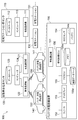
- FIG. 1 is a configuration diagram of a power supply system according to the present embodiment.
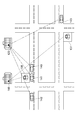
- FIG. 2 is an example of the arrangement of charging stations.
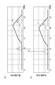
- FIG. 3 is a diagram illustrating the relationship between the amount of power consumed at the charging station and the traffic volume around the charging station.
- FIG. 3 shows temporal changes in the power consumption at the charging stations S1 and S2 and the traffic volume (the number of vehicles) around the charging stations S1 and S2. Note that, in the example shown in FIG. 3, for the sake of easy understanding, the tendency of changes in the electric energy and the traffic volume is the same.
- the amount of power consumed at the charging station depends on the traffic volume around it (especially the traffic volume of vehicles that can be charged from the outside), and changes slightly after the change in traffic volume. To do.
- the traffic volume around the charging station varies even at the same location due to various factors such as day of the week, weather, traffic restrictions, traffic jams, and the like. Therefore, by collecting the traffic volume around the charging station in real time (especially the traffic volume on the road in contact with the charging station), the amount of power consumed in the charging station (operation rate) can be calculated in real time using that traffic volume. Can be estimated.
- the power supply system 1 includes an automobile company center 10 for exchanging information, a power company center 20, a charging station center 30, vehicles 40, 41,... On-vehicle devices 42, charging stations 60, 61,. .. And power company 50 for exchanging power, and charging stations 60, 61,...
- the charging station system center 30 is based on the traffic flow (traffic information) of the surrounding road for each charging station so that the amount of electric power stored in the charging stations 60, 61,. The amount of power supplied to the charging station is controlled in real time.
- FIG. 1 Although only one automobile company center, electric power company center, and charging station center are depicted in FIG. 1, there may be a plurality of centers.
- a car company system center is provided for each car company
- a power company system center is provided for each power company
- a charging station system center is provided for each management company of the charging station.
- the automobile company center 10 is a center operated by an automobile company.
- the automobile company center 10 collects information from each of the vehicles 40, 41,..., And provides traffic information obtained by processing the collected information to the charging station system center 30. In the provision of this traffic information, an information provision fee may be charged from the charging station system center 30.
- This traffic information is information for each charging station 60, 61,... Managed by the charging station system center 30, the number of vehicles within a predetermined range from the charging station on the road in contact with the charging station, and the drive type of each vehicle. (Engine vehicle, plug-in hybrid vehicle, electric vehicle, etc.) and vehicle type (general vehicle, truck, bus, etc.).
- the information collected from the vehicle includes a drive type, a vehicle type, a current position, a destination, road information on traveling, a battery SOC [State Of Charge], and the like.
- the automobile company system center 10 includes a wired communication device 11, a wireless communication device 12, a database 13, and a computer 14.
- the wired communication device 11 is a device for performing wired communication with the charging station system center 30 and the like via a network.
- the wireless communication device 12 is a device for performing wireless communication with each of the vehicles 40, 41,.
- the database 13 is a database for storing information collected from each vehicle, road traffic information around each charging station, and the like.
- the computer 14 processes information transmitted from each of the vehicles 40, 41,... And generates traffic information of surrounding roads for each charging station. As the information processing, for each charging station 60, 61,..., A predetermined range from the charging station that is traveling on the road in contact with the charging station based on information collected from each vehicle 40, 41,.
- the vehicle information is extracted, and traffic information including information such as the number of the extracted vehicles, the drive type of each vehicle, the vehicle type, and the SOC is generated.
- traffic information including information such as the number of the extracted vehicles, the drive type of each vehicle, the vehicle type, and the SOC is generated.
- the collected vehicle information is transmitted as it is to the charging station center 30, and such information processing is performed at the charging station center 30. May be.
- Each vehicle 40, 41, ... is equipped with an in-vehicle device 42 for providing information.
- the in-vehicle device 42 includes a wireless communication device 43, a memory 44, an information processing ECU [Electronic Control Unit] 45, and the like.
- the wireless communication device 43 is a device for performing wireless communication with the automobile company system center 10.
- the memory 44 is a memory for storing information collected from each in-vehicle system, various types of vehicle information, and the like.
- the information processing ECU 45 collects information such as the current position and destination information from the navigation system (not shown) and SOC information from the SOC sensor (not shown), and collects the collected information and various vehicle information (drive). The information to be provided to the automobile company system center 10 is generated.
- the electric power company center 20 is a center operated by an electric power company 50 that supplies electric power.
- the power company center 20 receives an instruction for the amount of power supplied to the charging stations 60, 61,... From the charging station system center 30, the power company 50 immediately transmits a power transmission facility (not shown) according to the instruction. ) To send power.
- the electric power company center 20 includes a wired communication device 21, a database 22, and a computer 23.
- the wired communication device 21 is a device for performing wired communication with the charging station system center 30 and the like via a network.
- the database 22 stores power transmission history (number of times of power transmission, amount of transmitted power, etc.) and various information (location, allowable amount of electricity stored in the station, current amount of electricity stored, etc.) for each charging station 60, 61. Database.
- the computer 23 performs power supply control for a power transmission facility, management of power transmission information, and the like according to a power supply instruction transmitted from the charging station system center 30 or the like.
- the charging station system center 30 is a center operated by a company that manages the charging stations 60, 61.
- the charging station center 30 manages the charging station spec information, operation status information, and the like for each charging station 60, 61,. Further, in the charging station system center 30, for each charging station 60, 61,..., Electric power supplied to the charging station based on the operation status information of each charging device in the charging station and road traffic information around the charging station. Control the amount.
- the charging station system center 30 includes a wired communication device 31, a database 32, and a computer 33.
- the wired communication device 31 (which actually acquires traffic information is the automobile company system center 10) corresponds to the traffic information acquisition means described in the claims, and the computer 33 claims It corresponds to the control means described in the range.
- the wired communication device 31 is a device for performing wired communication with the automobile company system center 10, the power company system center 20, and the charging stations 60, 61,... Via the network.
- the database 32 includes various information for each charging station 60, 61,... (Location, spec information, operation status information, etc.), traffic information for each charging station 60, 61,. It is a database for storing.
- the specification information includes the allowable storage amount in the station, the current storage amount, the current of each charging device, the connector shape, the rated capacity, the number of phases, the voltage, the rated frequency, the rated power factor, and the like.
- the operation status information includes the number of times of charging for each charging device of the charging station, the charging time and the charging amount (power consumption) in each charging, and the like.
- the computer 33 When the computer 33 acquires the charging history for each charging device transmitted from the charging station for each of the charging stations 60, 61,..., The computer 33 generates operation status information from the charging history. Further, in the computer 33, the charging station 60, 61,... Is charged based on the traffic information around the charging station for each charging station 60, 61,. Estimate uptime. Then, the computer 33 controls the amount of power supplied to the charging station for each charging station 60, 61,... Based on the estimated operating rate.
- the number of vehicles that may use the charging station is predicted from the number of vehicles around the charging station, the drive type of each vehicle, the vehicle type, and the like. In this prediction, it is not a vehicle that is a motor-driven vehicle equipped with a battery that can be charged from the outside such as a plug-in hybrid vehicle or an electric vehicle, and a regular operation such as a bus (since regular operation uses its own infrastructure) Count vehicles that may charge on the go. At this time, by considering the SOC of the counted vehicle battery, the destination, and the like, vehicles that are unlikely to be charged at the destination are excluded from the counted number.
- the operating rate of the charging station is estimated based on the final vehicle count and the actual operating status information of the charging station. Basically, the greater the vehicle count, the higher the availability factor.
- the current operation rate may be estimated, or the operation rate after a predetermined time such as 30 minutes or 1 hour may be estimated.
- the operating rate may be an operating rate based on the charging time in the charging station or the number of vehicles to be used, but may be an operating rate based on the amount of power consumed by charging. Even if the charging time and the number of vehicles to be used are the same, the amount of power consumed by charging differs depending on the charging method, etc., so the operation rate based on the amount of power is more useful for controlling the amount of power supplied to the charging station. It is.
- the operating rate is estimated in consideration of the weather. For example, in the case of rain or snow, it is predicted that the number of vehicles to be charged will increase, so the operation rate is set higher than usual. In addition, when accident information and traffic regulation information can be obtained when estimating the operation rate, the operation rate is estimated in consideration of such information. When traffic jams occur due to accidents or traffic restrictions, it is predicted that more vehicles will be charged when it takes time to pass through the traffic jams, so the operating rate is set higher than usual.
- the power supply amount is set higher as the operation rate becomes higher, the power supply amount is set lower as the operation rate becomes lower, and the operation rate is lower (including the case of 0).
- the power supply is stopped.
- the power supply instruction indicating the set power supply amount or the power supply stop is normally issued to the power company center 20 and the power company 50 supplies power.
- the power charge from the power company 50 is high, the operating rate is low at other charging stations, and the amount of stored electricity in the station is excessive, power is supplied from the other charging stations.
- Each charging station 60, 61,... Has a wired communication device (not shown), and the specification information (especially the current storage amount in the station etc.) is sent to the charging station system center 30 at regular intervals.
- the charging history of each charging device is transmitted.
- FIG. 4 is a flowchart showing the flow of processing in the charging station system center of FIG.
- each charging station 60, 61,... Specification information (especially, the value such as the current amount of electricity stored in the station changes) and the charging history of each charging device are sent to the charging station system center 30 at regular intervals. Send.
- the wired communication device 31 receives information from each charging station 60, 61,..., And the computer 33 operates from the information for each charging station 60, 61,. Information is generated (S1).
- the wireless communication device 43 transmits information such as the current position, destination, battery SOC, drive type, vehicle type, etc. to the car company center 10. This transmission may be performed at regular intervals or in response to a request from the automobile company system center 10.
- the wireless communication device 12 receives information from each vehicle 40, 41,...,
- the computer 14 processes information from each vehicle 40, 41,. , 61,..., Generate traffic information (traffic flow) in the vicinity, and the wired communication device 11 transmits the traffic information for each charging station to the charging station system center 30.
- This transmission may be performed at regular intervals or in response to a request from the charging station system center 30.
- the wired communication device 31 receives the traffic information for each charging station from the automobile company system center 10 (S2).
- the computer 33 of the charging station system center 30 the actual operation status and surrounding traffic information of each charging station 60, 61,... At each fixed time (especially traffic flow that may use the charging station). Based on (number of vehicles)), the real-time operating rate of the charging station is estimated (S3). Then, the computer 33 of the charging station system center 30 controls the amount of power supplied to the charging station based on the operating rate of each charging station 60, 61,... At regular intervals (S4).
- the computer 33 determines the power supply amount based on the operation rate and generates a power supply instruction indicating the power supply amount and the charging station
- the wired communication device 31 generates the power supply.
- a supply instruction is transmitted to the power company center 20.
- the computer 23 performs power supply control on the power transmission facility according to the power supply instruction. As a result, power is supplied from the power transmission facility to the charging station by the amount of power supply indicated in the power supply instruction.
- the power supply amount to the charging station is controlled based on the traffic information of the roads around the charging station, so that an appropriate power is supplied to the charging station in real time. Supply can be made. As a result, the amount of power stored in the charging station is always an appropriate amount, and it is possible to prevent the amount of power from being excessive and insufficient.
- the computer 33 of the charging station system center 30 estimates the operating rate of the charging station in consideration of traffic information on the road around the charging station (particularly, traffic flow (number of vehicles) that may use the charging station).
- traffic information on the road around the charging station particularly, traffic flow (number of vehicles) that may use the charging station.
- the real-time operation rate at the charging station can be estimated with high accuracy, and the amount of power required at the charging station can be determined from the operation rate in real time.
- the power supply system is composed of three centers, that is, a charging station system center, an automobile company system center, and an electric power company system center, but the center may be integrated into one or two, or the weather
- the system may also include other centers such as a center that manages traffic accidents, a center that manages traffic accidents and traffic regulations, and the like.
- the charging station system center is configured to control the amount of power of each charging station in real time based on traffic information.
- the charging station system center is configured to control the amount of power of each charging station in real time based on traffic information.
- other centers such as an automobile company center and an electric power company center, May be controlled.
- the traffic information is generated based on the information collected from each vehicle at the automobile company center.
- traffic information such as VICS [Vehicle Information and Communication System] information may be used.
- VICS Vehicle Information and Communication System
- the charging station system center is provided with a VICS receiver.
- the power supply system may be a system in which a power sorting company is interposed in the power network.
- the power sorting business is a business that performs power sorting in the power supply from the power company to each charging station, the power supply between the charging stations, and other power exchanges.
- the power sorting business is provided for each region, for example, and is operated by a charging station management company, a power company, or a completely different company.
- a communication line for transmitting and receiving information may be provided on a power line for charging the vehicle from the charging device of the charging station, and wired communication may be possible between the vehicle and the charging device.
- information from the vehicle can also be collected at the charging station (and eventually the charging station system center).
- the computer of the charging station system center determines the amount of power supplied to the charging station, and power corresponding to the amount of power supplied is supplied from the power transmission facility of the power company to the charging station.
- at least a part of the power supply amount determined by the computer of the charging station system center may be covered by private power generation (for example, power generation using a fuel cell) at the charging station.
- the computer of the charging station system center controls the power supply amount to the charging station by changing at least one of the power generation amount of the private power generation at the charging station and the storage amount of the storage battery of the charging station. Can do.
- the information providing device is applied to a battery charge induction device mounted on a vehicle in a battery charge induction system.
- the battery charging induction system according to the present embodiment is capable of wired communication between the charging station system center and the automobile company system center. Further, in the battery charging induction system according to the present embodiment, the charging station system center can communicate with each charging station in a wired manner, and the automobile company system center can communicate with each vehicle wirelessly.
- FIG. 5 is a configuration diagram of the battery charging induction system according to the present embodiment.
- FIG. 6 is an example of the arrangement of charging stations.
- the battery charging induction system 100 includes a charging station system center 110, an automobile company center 120, charging stations 130, 131,..., Vehicles 140, 141,. Is done.
- in-vehicle battery charging induction device 150 when the host vehicle needs to be charged, it conforms to the specifications relating to the charging of the host vehicle from among the charging stations in the travelable range of the host vehicle and the waiting time is as short as possible. Select a charging station and direct to that charging station.
- charging station system center and automobile company system center are shown in FIG. 5, but there may be a plurality of centers.
- a charging station system center is provided for each management company of the charging station, and an automobile company system center is provided for each automobile company.
- the charging station system center 110 is a center operated by a company that manages the charging stations 130, 131.
- the charging station system center 110 collects information from the charging stations 130, 131,... And provides the car company system center 120 with spec information and operation status information obtained by processing the collected information.
- the charging station system center 110 includes a wired communication device 111, a database 112, and a computer 113.
- the wired communication device 111 is a device for performing wired communication with the automobile company system center 120 and the charging stations 130, 131,... Via the network.
- the database 112 is a database for storing various information (position information, spec information, operation status information, etc.) for each charging station 130, 131.
- the specification information includes the allowable storage amount in the station, the current storage amount, the connector shape of each charging device, the output current, the output voltage, the number of phases, the rated capacity, the rated frequency, the rated power factor, and the like.
- the operating status information includes the number of charging devices being charged in the charging station, the estimated charging completion time for each charging device being charged), and the like.
- the computer 113 acquires information transmitted from the charging station for each of the charging stations 130, 131,...
- Operation status information is generated from this information.
- specification information including the specification is generated.
- specifications known in advance such as the allowable charge amount in the station and the connector shape of each charging device are stored in the database 112.
- Each charging station 130, 131,... Has a wired communication device (not shown), and information regarding specifications such as the current amount of electricity stored in the station and whether charging is being performed for each charging device at regular time intervals. If not, or if charging is in progress, information on the operating status such as the estimated charging completion time is transmitted to the charging station system center 110.
- the automobile company center 120 is a center operated by an automobile company.
- the automobile company system center 120 collects information from each vehicle, and provides traffic information obtained by processing the collected information in response to a request from the vehicles 140, 141,.
- This traffic information is information for each charging station 130, 131,..., And the number of vehicles within a predetermined range from the charging station on the road in contact with the charging station, the drive type of each vehicle (engine vehicle, plug-in hybrid vehicle) , Electric vehicle, etc.), vehicle type (general vehicle, truck, bus, etc.), destination, battery SOC [State Of Charge], etc.
- Information collected from the vehicle includes a drive type, a vehicle type, a current position, a destination, road information on traveling, a battery SOC, and the like.
- the automobile company system center 120 collects spec information and operation status information for each of the charging stations 130, 131,... From the charging station system center 110, and uses the information as a vehicle 140, on which the battery charging induction device 150 is mounted. 141, etc. are provided upon request.
- the automobile company system center 120 includes a wired communication device 121, a wireless communication device 122, a database 123, and a computer 124.
- the wired communication device 121 is a device for performing wired communication with the charging station system center 110 and the like via a network.
- the wireless communication device 122 is a device for performing wireless communication with each vehicle.
- the database 123 is a database for storing information collected from each vehicle, road traffic information around each charging station, specification information and operation status information of each charging station, and the like.
- the computer 124 processes information transmitted from each vehicle to generate road traffic information around the charging station.
- This information processing for each charging station 130, 131,..., A vehicle within a predetermined range is extracted from a charging station traveling on a road in contact with the charging station based on information collected from each vehicle, Traffic information including information such as the number of extracted vehicles, the drive type of each vehicle, the vehicle type, the destination, and the SOC is generated.
- Traffic information including information such as the number of extracted vehicles, the drive type of each vehicle, the vehicle type, the destination, and the SOC is generated.
- the computer 124 receives a request for providing information about a charging station from a vehicle on which the battery charging induction device 150 is mounted, the specification information, operating status information, and traffic around the charging station are stored in the database 123. Each piece of information is extracted, and information about each extracted charging station is transmitted to the vehicle using the wireless communication device 122.
- Each vehicle 140, 141,... Is a vehicle that uses external electric energy that can be charged from the outside to a battery such as a plug-in hybrid or an electric vehicle, and is equipped with a battery charge induction device 150.
- the battery charge induction device 150 determines whether or not the battery needs to be charged in order for the vehicle to travel to the destination. Provide information to guide the charging station (and low latency).
- the battery charge induction device 150 includes a wireless communication device 151, a speaker 152, a display 153, an SOC sensor 154, a navigation ECU [Electronic Control Unit] 155, an information processing ECU 156, and the like.
- the map database 155a (when charging station location information and the like are stored) and the wireless communication device 151 (the charging station system center 110 actually acquires the information) are claimed.
- the wireless communication device 151 corresponds to the traffic flow acquisition means described in the claims, and corresponds to the information processing ECU 156. Corresponds to the charging station determination means described in the claims.
- the wireless communication device 151 is a device for performing wireless communication with the automobile company system center 120.
- the speaker 152 is an in-vehicle speaker used in a navigation device or the like. For example, when the speaker 152 receives a sound signal for outputting a sound from the navigation ECU 155, the speaker 152 outputs a sound according to the sound signal.
- the display 153 is an in-vehicle display used in a navigation device or the like. For example, when receiving a display signal for displaying an image from the navigation ECU 155, the display 153 displays an image in accordance with the display signal.
- the SOC sensor 154 is a sensor that detects the SOC (remaining charge amount) of the in-vehicle battery 154a.
- the battery 154a is a battery that can be charged from the outside, and is used to drive a motor.
- the navigation ECU 155 includes a CPU [Central Processing Unit], various memories, and the like, and is an electronic control unit of a navigation device (not shown).
- the navigation ECU 155 has a current position calculation function, a map display function, a destination setting function, a route search function, a route guidance function, and the like.
- the current position calculation function uses the map matching map data stored in the map database 155a to detect the detection values of various sensors such as a vehicle speed sensor and a gyro sensor and the GPS information received by the GPS [global positioning system] receiver. Based on this, the current position and traveling direction of the host vehicle are calculated.
- the destination setting function uses the destination setting data stored in the map database 155a to generate a destination setting image in accordance with operation information from an input device such as a touch display, and displays the display signal. Send to display 153.
- the route search function when the destination is set, the route from the current position to the destination is searched using the route search data stored in the map database 155a.
- the route guidance function every time the current position is updated, the current position is compared with the guidance point on the route, and when the current position approaches the guidance point, the voice guidance for the guidance point stored in the map database 155a is output.
- the guidance voice is generated using the data and the voice signal is transmitted to the speaker 152, and the guidance image is generated using the display data of the guidance point stored in the map database 155a and the display signal is displayed.
- the route guidance function calculates the remaining distance to the destination and the arrival time each time the current position is updated.
- the information processing ECU 156 is composed of a CPU, various memories, and the like, and is an integrated electronic control unit of an information processing system.
- the information processing ECU 156 has a battery charge induction function for performing main processing of the battery charge induction device 150.
- this battery charge induction function will be described below.
- the information processing ECU 156 temporarily stores the detected value in the memory 156a every time the SOC sensor 154 detects the SOC of the battery 154a. Further, each time the navigation ECU 155 updates the route information, the information processing ECU 156 temporarily stores the route information (particularly, the remaining distance to the destination) in the memory 156a.
- the route information can be obtained from the in-vehicle navigation device in this way when the navigation device is installed, but when the navigation device is not installed, the center outside the vehicle (for example, the car company center 120). ). If the user of the host vehicle has not set a destination, the destination is estimated and route information for the estimated destination is used.
- the information processing ECU 156 calculates the charge amount of the battery 154a (necessary estimated battery charge amount) required when the vehicle travels the remaining distance to the destination based on the SOC of the battery 154a and the route information.
- the required estimated battery charge amount is the effective use range of the battery 154a after subtracting the amount of power consumed when the remaining distance from the current SOC of the battery 154a to the destination is driven by the motor alone. It is the amount corresponding to the amount below the lower limit. In other words, if the SOC after subtraction is below the lower limit of the effective use range of the battery 154a, the current SOC of the battery 154a is insufficient to run to the destination with only the motor, so at least the necessary estimated battery charge amount is required.
- the SOC When the battery 154a is charged, the SOC is within the effective use range of the battery 154a when the destination is reached. On the other hand, if the SOC after the subtraction is higher than the lower limit of the effective use range of the battery 154a, the SOC is not charged when the current SOC of the battery 154a travels with the motor alone to reach the destination. Since it is within the effective use range of 154a, there is no need to charge the battery 154a. In this case, the required estimated battery charge amount is set to zero.
- the information processing ECU 156 determines whether or not it is necessary to charge the battery 154a to the destination based on the required estimated battery charge amount.
- the required estimated battery charge amount is 0, it is determined that charging is not necessary, and when the required estimated battery charge amount is greater than 0, it is determined that charging is necessary.
- the determination may be performed with a certain margin.
- the reason for providing a margin is safety considerations such as sudden use of the power of the battery 154a for emergency avoidance or the like.
- the information processing ECU 156 determines that the battery 154a needs to be charged, the information processing ECU 156 is included in the travelable range of the host vehicle based on a database (map database 155a) that stores information about the charging station (particularly position information). Search for charging stations.
- the travelable range may be within a range along a route from the current position of the host vehicle to the destination, or may be within a predetermined range centered on the route. Further, the travelable range may be a range including all the routes to the destination, or may be a route within a certain distance from the current position among the routes to the destination.
- the travelable range of the host vehicle is transmitted to the automobile company center 120, and the travelable range of the vehicle company center 120 or the charging station system center 110 is transmitted. Have a search for a charging station inside.
- the information processing ECU 156 uses the wireless communication device 151 to transmit an information provision request for each charging station within the travelable range to the automobile company center 120. Then, the information processing ECU 156 acquires the specification information and the operation status information for each charging station from the automobile company center 120 received by the wireless communication device 151, and temporarily stores the acquired information in the memory 156a. In addition, the information processing ECU 156 acquires traffic information around each charging station from the automobile company center 120 received by the wireless communication device 151, and temporarily stores the acquired information in the memory 156a.
- the information processing ECU 156 selects an optimum charging station for the host vehicle from the charging stations within the travelable range, based on the specification information, operation status information, and surrounding traffic information of each charging station.
- a charging station having specifications that match specifications related to charging of the host vehicle (this specification information is stored in advance in the memory 156a) is selected.
- this specification information is stored in advance in the memory 156a
- the connector shape for charging the host vehicle and the connector shape of the charging device at the charging station match, the number of alternating current phases on the host vehicle side and the charging station side match, and the input current range when charging the host vehicle and A charging station having specifications that allow charging from the charging device of the charging station in the input voltage range is selected.
- the congestion level of the charging station is estimated from the operating status information of the charging station and the surrounding traffic information, and the congestion level is the lowest among the charging stations that meet the specifications (the waiting time until charging is the least (waiting time) Including the case of 0)))
- Select a charging station is a motor-driven vehicle equipped with a battery that can be charged from the outside such as plug-in hybrid vehicles and electric vehicles from the surrounding traffic information, and regular operations such as buses (since regular operations use their own infrastructure) Count vehicles that are likely to be charged when they are not vehicles.
- the degree of mixture (operation rate) after a predetermined time of the charging station (for example, the time required for the host vehicle to reach the charging station) is estimated. Basically, the greater the number of vehicles that can be charged, the higher the degree of congestion.
- the information processing ECU 156 indicates that the remaining charge amount of the battery is insufficient before reaching the destination and information on the charging station selected as the optimal charging station for charging (for example, position information, distance to the station, arrival time, In order to generate a sound for notifying a charge amount and a charge time (normal charge, quick charge) for charging a required estimated battery charge amount, and transmitting the sound signal to the speaker 152 or displaying them And the display signal is transmitted to the display 153.
- the information processing ECU 156 not only displays and displays information on the selected charging station, but also passes the charging station to the navigation ECU 155 (navigation device) as a transit point, and the route search function of the navigation ECU 155 leads to the charging station. The route may be searched and the route to the charging station may be displayed on the map, or the route guidance function of the navigation ECU 155 may be used to guide the route to the charging station.
- an in-vehicle device for providing information to the automobile company center 120 is mounted.
- This in-vehicle device includes a wireless communication device, a memory, an information processing ECU, and the like, and information such as a drive type, a vehicle type, a current position, a destination, road information on traveling, a battery SOC, etc. Send to.
- FIG. 7 is a flowchart showing a flow of processing in the in-vehicle battery charging induction device of FIG.
- each charging station 130, 131,... Information about specifications (especially, a value such as a current power storage amount in the station changes), whether charging is being performed for each charging device, and charging is being performed.
- information such as the estimated charging completion time is transmitted to the charging station system center 110.
- the charging station system center 110 information from each charging station 130, 131,... Is received by the wired communication device 111 at regular intervals, and the computer 113 currently receives the information for each charging station 130, 131,.
- Spec information and operation status information including information for changing the value such as the amount of stored electricity is generated.
- the wired communication device 111 transmits the specification information and operation status information for each of the charging stations 130, 131,.
- the wired communication device 111 receives the specification information and operation status information for each of the charging stations 130, 131,... From the charging station system center 110, and the received information is used as the charging stations 130, 131. ,... Are stored in the database 123 for each.
- Information such as driving type, vehicle type, current position, destination, road information on the road, SOC of the battery 154a, etc. is obtained from the automobile company system at a certain time interval. Transmit to the center 120.
- the wireless communication device 122 receives these pieces of information from the respective vehicles 140, 141,..., And generates surrounding traffic information for each charging station 130, 131,. The generated information is stored in the database 123 for each charging station 130, 131,.
- the following processing is repeatedly executed at regular time intervals.
- the SOC sensor 154 detects the SOC (remaining charge amount) of the battery 154a (S11).
- the information processing ECU 156 the SOC of the battery 154a is taken into the ECU.
- the navigation ECU 155 searches for a route to the destination when the destination is set, and calculates a remaining distance from the current position along the route to the destination every time the current position is updated (S12). ).
- the information processing ECU 156 takes route information such as the remaining distance to the destination into the ECU.
- the information processing ECU 156 calculates the required estimated battery charge amount based on the SOC of the battery 154a and the route information (particularly, the remaining distance to the destination) (S13). Then, the information processing ECU 156 determines whether or not charging is necessary to reach the destination based on the necessary estimated battery charge amount (S14). If it is determined in S14 that charging is unnecessary, the current process is terminated.
- the information processing ECU 156 searches for a charging station within the travelable range of the host vehicle, and issues a request to provide information about the charging station within the travelable range with the wireless communication device 151. Transmit to the system center 120.
- the information communication request is received by the wireless communication device 122, and the spec information, the operation status information, and the charging station surroundings for each charging station indicated in the information providing request from the database 123 by the computer 124.
- the information on each charging station extracted by the wireless communication device 122 is transmitted to the vehicle (battery charging induction device 150).
- the wireless communication device 151 receives the information, acquires spec information and operating status information about each charging station within the travelable range of the host vehicle (S15), and Traffic information is acquired (S16).
- the information processing ECU 156 From among the charging stations within the travelable range of the host vehicle, the spec information, the operation status information, and the surrounding traffic information (especially, the traffic flow of the vehicle using external electric energy) about each charging station. Based on this, the optimum charging station for the host vehicle is selected (S17). Then, the information processing ECU 156 outputs an audio signal for notifying information related to the selected charging station (for example, position information, distance and arrival time to the station, route information to the station, guidance information to the station). Or a display signal for displaying them is transmitted to the display 153 (S18). When the speaker 152 receives the sound signal, the speaker 152 outputs information on the optimum charging station as a sound (S18). When the display signal is received, the display 153 displays information on the optimum charging station (S18).
- the display 153 displays information on the optimum charging station (S18).
- this battery charge induction system 100 (particularly, battery charge induction device 150), it is based on traffic information around the charging station (particularly, the number of vehicles that use external electrical energy (vehicles that may be battery charged)).
- traffic information around the charging station particularly, the number of vehicles that use external electrical energy (vehicles that may be battery charged)
- By selecting the charging station it is possible to select a charging station suitable for the host vehicle that needs charging, and to guide to the charging station.
- charging can be started with little or no waiting time, and a sufficient charging time can be secured.
- normal charging is possible if the user of the host vehicle desires.
- the battery can be fully charged and deterioration of the battery can be suppressed.
- the charging station is selected based on the specification information (particularly, the specification information of the charging device) at the charging station, so that the specification relating to charging in the host vehicle that needs to be charged is met.
- a charging station equipped with a charging device can be selected. By the way, even a charging station with a low waiting time cannot be charged without a charging device that meets the specifications.
- the battery charging induction system is composed of two centers, a charging station system center and an automobile company system center, but the center may be integrated into one, or may be a system including other centers. Good.
- the battery charge induction device for guiding the optimal charging station is used.
- the present invention may be applied to a device that only provides information on the optimal charging station.
- the traffic information is generated based on the information collected from each vehicle at the automobile company center, but may be other traffic information such as VICS [Vehicle Information and Communication System] information.
- VICS Vehicle Information and Communication System
- the vehicle company center or each vehicle is provided with a VICS receiver.
- the information processing ECU performs the main processing of the battery charging induction device, but it may be performed by another ECU such as a navigation ECU or a dedicated ECU.
- the battery charge induction device (information providing device) is a device mounted on a vehicle.
- the battery charge induction device (information providing device) is configured outside a vehicle such as an automobile company center, and is optimally charged by wireless communication or the like from the device outside the vehicle. You may make it transmit the information of a station to a vehicle.
- whether or not charging is necessary is determined by calculating a necessary estimated battery charge amount and determining based on the required estimated battery charge amount.
- the charging station selection method based on the charging station specification information, the operation status information, and the traffic information around the charging station is shown, but the charging station may be selected by other methods.
- the number of vehicles that may be charged is obtained from traffic information around the charging station as the traffic flow of vehicles using external electrical energy around the charging station.
- the traffic flow of the vehicle using external electric energy may be other parameters such as the degree of traffic jam of the vehicle using external electric energy and the travel time between points.
- the specifications for charging vehicles that can be charged from the outside are standardized and the charging station side also supports the specifications, there is no need to determine the specification information on the vehicle side and the charging station side. What is necessary is just to select a charging station based only on traffic information (and the operation status information of a charging station if necessary).
- a communication line for transmitting and receiving information may be provided on a power line for charging the vehicle from the charging device of the charging station, and wired communication may be possible between the vehicle and the charging device.
- information from the vehicle can also be collected at the charging station (and eventually the charging station system center).
- SYMBOLS 1 Electric power supply system, 10 ... Automobile company center, 11, 21, 31 ... Wired communication machine, 12, 43 ... Wireless communication machine, 13, 22, 32 ... Database, 14, 23, 33 ... Computer, 20 ... Electric power Company system center, 30 ... charging station system center, 40, 41 ... vehicle, 42 ... vehicle equipment, 44 ... memory, 45 ... information processing ECU, 50 ... electric power company, 60,61 ... charge station, 100 ... battery charge induction system 110, charging station system center, 111, 121 ... wired communication device, 112, 123 ... database, 113, 124 ... computer, 120 ... automobile company system center, 122, 151 ... wireless communication device, 130, 131 ...
- charging station 140, 141, 142, 143 ... vehicle, 150 ... battery charge induction device, 152 ... speed , 153 ... display, 154 ... SOC sensor, 154a ... battery, 155 ... navigation ECU, 155a ... map database 156 ... information processing ECU, 156a ... memory.
Landscapes
- Engineering & Computer Science (AREA)
- Power Engineering (AREA)
- Transportation (AREA)
- Mechanical Engineering (AREA)
- Sustainable Energy (AREA)
- Sustainable Development (AREA)
- Life Sciences & Earth Sciences (AREA)
- Charge And Discharge Circuits For Batteries Or The Like (AREA)
- Electric Propulsion And Braking For Vehicles (AREA)
- Traffic Control Systems (AREA)
- Management, Administration, Business Operations System, And Electronic Commerce (AREA)
- Navigation (AREA)
- Remote Monitoring And Control Of Power-Distribution Networks (AREA)
Abstract
Description
Claims (11)
- 充電ステーションへの電力供給を制御する電力供給制御装置であって、
充電ステーション周辺の道路の交通情報を取得する交通情報取得手段と、
前記交通情報取得手段で取得した充電ステーション周辺の道路の交通情報に基づいて充電ステーションへの電力供給量を制御する制御手段と、
を備えることを特徴とする電力供給制御装置。 - 前記制御手段は、前記交通情報に基づいて充電ステーションの稼働率を推定すると共に、推定した前記稼動率に基づいて充電ステーションへの電力供給量を制御する、ことを特徴とする請求項1に記載の電力供給制御装置。
- 前記制御手段は、外部から充電可能なバッテリを備えるモータ駆動車であって充電する可能性のある車両を前記交通情報に基づいてカウントし、そのカウント数と充電ステーションの実際の稼動状況とに基づいて前記稼働率を推定する、ことを特徴とする請求項2に記載の電力供給制御装置。
- 前記制御手段は、前記稼動率の推定に際して、天候情報、事故情報、及び交通規制情報の少なくとも1つを考慮する、ことを特徴とする請求項2又は3に記載の電力供給制御装置。
- 前記制御手段は、充電ステーションにおける自家発電の発電量、及び充電ステーションの蓄電池の蓄電量の少なくとも一方を変更することにより、充電ステーションへの電力供給量を制御する、ことを特徴とする請求項1~4のいずれか一項に記載の電力供給制御装置。
- 充電を必要とする車両に充電ステーションに関する情報を提供する情報提供装置であって、
充電ステーションの情報を取得する充電ステーション情報取得手段と、
前記充電ステーション情報取得手段で情報を取得した充電ステーション毎に、充電ステーション周辺における外部電気エネルギを使用する車両の交通流を取得する交通流取得手段と、
前記交通流取得手段で取得した各充電ステーション周辺における外部電気エネルギを使用する車両の交通流に基づいて、前記充電ステーション情報取得手段で情報を取得した充電ステーションの中から情報提供する充電ステーションを決定する充電ステーション決定手段と、
を備えることを特徴とする情報提供装置。 - 前記充電ステーション情報取得手段は、充電ステーションに装備される充電装置のスペック情報を取得し、
前記充電ステーション決定手段は、前記充電ステーション情報取得手段で取得した充電装置のスペック情報に基づいて、前記充電を必要とする車両の充電に関するスペックに適合したスペックを有する充電装置が装備される充電ステーションの中から情報提供する充電ステーションを決定する、ことを特徴とする請求項6に記載の情報提供装置。 - 前記充電ステーション情報取得手段は、充電ステーションの稼動状況情報を取得し、
前記充電ステーション決定手段は、前記充電ステーション情報取得手段で取得した前記稼動状況情報と前記交通流取得手段で取得した前記交通流とに基づいて充電ステーションの混雑度合いを推定すると共に、推定した前記混雑度合いに基づいて情報提供する充電ステーションを決定する、ことを特徴とする請求項6又は7に記載の情報提供装置。 - 前記充電ステーション決定手段は、情報提供する充電ステーションの決定に際し、充電用の電力量が不足する可能性のある充電ステーションを除外する、ことを特徴とする請求項6~8のいずれか一項に記載の情報提供装置。
- 前記交通流は、充電ステーション周辺における外部電気エネルギを使用する車両の台数である、ことを特徴とする請求項6~9のいずれか一項に記載の情報提供装置。
- 前記充電を必要とする車両に搭載されている、ことを特徴とする請求項6~10のいずれか一項に記載の情報提供装置。
Priority Applications (4)
| Application Number | Priority Date | Filing Date | Title |
|---|---|---|---|
| DE112011100624.1T DE112011100624B4 (de) | 2010-02-22 | 2011-02-21 | Energieversorgungssteuervorrichtung und Informationsbereitstellungsvorrichtung |
| CN201180010379.9A CN102770304B (zh) | 2010-02-22 | 2011-02-21 | 电力供给控制装置以及信息提供装置 |
| US13/519,533 US9126493B2 (en) | 2010-02-22 | 2011-02-21 | Power supply control device and information provision device |
| JP2012500685A JP5553106B2 (ja) | 2010-02-22 | 2011-02-21 | 電力供給制御装置 |
Applications Claiming Priority (4)
| Application Number | Priority Date | Filing Date | Title |
|---|---|---|---|
| JP2010036094 | 2010-02-22 | ||
| JP2010-036094 | 2010-02-22 | ||
| JP2010-044094 | 2010-03-01 | ||
| JP2010044094 | 2010-03-01 |
Publications (1)
| Publication Number | Publication Date |
|---|---|
| WO2011102515A1 true WO2011102515A1 (ja) | 2011-08-25 |
Family
ID=44483098
Family Applications (1)
| Application Number | Title | Priority Date | Filing Date |
|---|---|---|---|
| PCT/JP2011/053746 Ceased WO2011102515A1 (ja) | 2010-02-22 | 2011-02-21 | 電力供給制御装置、及び情報提供装置 |
Country Status (5)
| Country | Link |
|---|---|
| US (1) | US9126493B2 (ja) |
| JP (2) | JP5553106B2 (ja) |
| CN (2) | CN104182492B (ja) |
| DE (1) | DE112011100624B4 (ja) |
| WO (1) | WO2011102515A1 (ja) |
Cited By (14)
| Publication number | Priority date | Publication date | Assignee | Title |
|---|---|---|---|---|
| JP2011238182A (ja) * | 2010-05-13 | 2011-11-24 | Central Res Inst Of Electric Power Ind | 交通シミュレーションプログラム、交通シミュレーション装置及び交通シミュレーション方法 |
| WO2013038858A1 (ja) * | 2011-09-16 | 2013-03-21 | 三菱重工業株式会社 | 充電スタンド管理システム、制御方法、及びプログラム |
| WO2013073625A1 (ja) * | 2011-11-15 | 2013-05-23 | 株式会社 東芝 | 課金システム及びev充電システム |
| EP2717016A1 (en) * | 2012-10-05 | 2014-04-09 | Hitachi, Ltd. | Method and system for providing route assistance for electric vehicles |
| JPWO2012086167A1 (ja) * | 2010-12-21 | 2014-05-22 | 日本電気株式会社 | 急速充電システム、制御装置、蓄電量の制御方法、及びプログラム |
| WO2014084305A1 (ja) * | 2012-11-30 | 2014-06-05 | 株式会社 東芝 | 充電管理装置 |
| WO2014162609A1 (ja) * | 2013-04-05 | 2014-10-09 | パイオニア株式会社 | 情報収集装置、情報送信装置、情報受信装置、情報収集方法および情報収集プログラム |
| JP2014532390A (ja) * | 2011-09-29 | 2014-12-04 | エヌイーシー ヨーロッパ リミテッドNec Europe Ltd. | 電気自動車を充電する方法およびシステム |
| US20150081149A1 (en) * | 2012-03-13 | 2015-03-19 | Hitachi Automotive Systems, Ltd. | Communications Device for Vehicle and Communications System for Vehicle |
| CN105608543A (zh) * | 2016-03-16 | 2016-05-25 | 福建工程学院 | 充电站配电量配置方法 |
| JP2018018454A (ja) * | 2016-07-29 | 2018-02-01 | 本田技研工業株式会社 | 情報処理システム、情報処理方法及びプログラム |
| WO2020189076A1 (ja) * | 2019-03-19 | 2020-09-24 | 本田技研工業株式会社 | 特定装置、特定方法およびプログラム |
| JP2022083304A (ja) * | 2020-11-24 | 2022-06-03 | トヨタ自動車株式会社 | 充電制御システム、充電制御装置および充電制御プログラム |
| US20230137396A1 (en) * | 2021-10-28 | 2023-05-04 | Atieva, Inc. | Cord set for v2v, v2l, or g2v charging or power supply |
Families Citing this family (65)
| Publication number | Priority date | Publication date | Assignee | Title |
|---|---|---|---|---|
| JP5493510B2 (ja) * | 2009-07-01 | 2014-05-14 | 日産自動車株式会社 | 情報提供システム、情報センタ、車載装置及び情報提供方法 |
| JP5786357B2 (ja) * | 2010-04-14 | 2015-09-30 | 日産自動車株式会社 | 充電施設情報管理装置および充電実績情報管理方法 |
| JP5494270B2 (ja) * | 2010-06-17 | 2014-05-14 | 日産自動車株式会社 | 情報提供装置および情報提供方法 |
| EP2769870A4 (en) * | 2011-10-20 | 2016-01-27 | Lsis Co Ltd | ELECTRIC VEHICLE AND OPERATING METHOD THEREFOR |
| US20130175985A1 (en) * | 2012-01-10 | 2013-07-11 | Thomas Percich | Rapid charge, on-the-go transportation system |
| US8849742B2 (en) | 2012-01-24 | 2014-09-30 | Ford Global Technologies, Llc | Method and apparatus for providing charging state alerts |
| US9971353B2 (en) * | 2012-07-03 | 2018-05-15 | Qualcomm Incorporated | Systems, methods, and apparatus related to electric vehicle parking and wireless charging |
| JP2015011576A (ja) * | 2013-06-28 | 2015-01-19 | 株式会社東芝 | 蓄電池駆動車両の運行システム |
| US9199548B2 (en) | 2013-09-30 | 2015-12-01 | Elwha Llc | Communication and control regarding electricity provider for wireless electric vehicle electrical energy transfer |
| US10093194B2 (en) * | 2013-09-30 | 2018-10-09 | Elwha Llc | Communication and control system and method regarding electric vehicle for wireless electric vehicle electrical energy transfer |
| US20150091503A1 (en) * | 2013-09-30 | 2015-04-02 | Elwha Llc | Communication and Control System and Method Regarding Electric Vehicle Charging Equipment for Wireless Electric Vehicle Electrical Energy Transfer |
| US20150091507A1 (en) * | 2013-09-30 | 2015-04-02 | Elwha Llc | Dwelling related information center associated with communication and control system and method for wireless electric vehicle electrical energy transfer |
| KR101459968B1 (ko) * | 2013-11-19 | 2014-11-10 | 현대자동차주식회사 | 전기자동차 충전 요구량 검증 방법 및 이에 사용되는 시스템 |
| US20150165915A1 (en) * | 2013-12-16 | 2015-06-18 | Honda Motor Co., Ltd. | Vehicle charging system |
| US20150226566A1 (en) * | 2014-02-07 | 2015-08-13 | Recargo, Inc. | Determining a route of travel for an electric vehicle |
| WO2015121852A1 (en) * | 2014-02-13 | 2015-08-20 | Reinhold Cohn And Partners | Control system for electric vehicle service network |
| WO2015140954A1 (ja) * | 2014-03-19 | 2015-09-24 | 日産自動車株式会社 | 作業員管理装置、作業員管理システム及び作業員管理方法 |
| CN103935259B (zh) * | 2014-03-31 | 2016-04-06 | 同济大学 | 基于耗电量的电动汽车最优路径查找方法 |
| JP5868454B2 (ja) * | 2014-06-09 | 2016-02-24 | 三菱電機株式会社 | 充電設備情報提供システムおよび電動車両 |
| JP6481344B2 (ja) * | 2014-11-27 | 2019-03-13 | 株式会社Ihi | 情報提供システム、受電装置、情報提供方法、および情報提供プログラム |
| JP6531827B2 (ja) * | 2015-07-31 | 2019-06-19 | 日産自動車株式会社 | 電動車両の充電支援方法及び充電支援装置 |
| KR20170069092A (ko) * | 2015-12-10 | 2017-06-20 | 현대자동차주식회사 | Avn 장치 및 이를 이용한 충전소 정보 제공 방법 |
| US10800284B2 (en) * | 2016-01-20 | 2020-10-13 | Ford Global Technologies, Llc | Charging strategies to mitigate lithium plating in electrified vehicle battery |
| CN105634068B (zh) * | 2016-02-04 | 2017-04-05 | 广州市一电设备安装有限公司 | 一种基于交通信息的电动汽车充电站 |
| CN105957252B (zh) * | 2016-02-04 | 2018-08-03 | 中惠创智无线供电技术有限公司 | 基于射频识别的多功能充电桩 |
| US10180333B2 (en) * | 2016-08-12 | 2019-01-15 | Ford Global Technologies, Llc | Crowd-sourced electric vehicle charging station identification |
| US10723230B2 (en) * | 2016-09-07 | 2020-07-28 | Thunder Power New Energy Vehicle Development Company Limited | Intelligent vehicle charging |
| JP6909971B2 (ja) * | 2017-03-29 | 2021-07-28 | パナソニックIpマネジメント株式会社 | 売電情報通知装置、売電情報通知方法および充電システム |
| CN107525515B (zh) * | 2017-09-15 | 2018-03-30 | 爱驰汽车有限公司 | 应用于新能源汽车的充电设备搜索方法、系统及电子设备 |
| JP6904217B2 (ja) * | 2017-11-01 | 2021-07-14 | トヨタ自動車株式会社 | 情報提供システム、サーバおよび情報提供方法 |
| EP3498520B1 (en) * | 2017-12-18 | 2023-05-03 | Volvo Car Corporation | Method and system for providing an advice to an occupant of an electrical vehicle |
| JP7003639B2 (ja) * | 2017-12-26 | 2022-01-20 | トヨタ自動車株式会社 | 電気自動車 |
| JP2019118219A (ja) * | 2017-12-27 | 2019-07-18 | トヨタ自動車株式会社 | 走行エネルギー分配システム、走行エネルギー分配方法および走行エネルギー分配プログラム |
| CA3088914C (en) | 2017-12-28 | 2023-10-03 | Tao Wei | Navigation method and system for electric vehicles based on electricity quantity guidance of energy-storage charging piles |
| CN107953798B (zh) * | 2017-12-28 | 2020-07-24 | 北京万开天盛科技有限公司 | 基于蓄能充电桩电量引导的电动运载工具导航方法及系统 |
| US10596920B2 (en) * | 2018-01-15 | 2020-03-24 | Ford Global Technologies, Llc | Vehicle charging system |
| WO2019159475A1 (ja) * | 2018-02-13 | 2019-08-22 | 本田技研工業株式会社 | 制御装置、制御方法、及びプログラム |
| US20190275893A1 (en) * | 2018-03-06 | 2019-09-12 | Wellen Sham | Intelligent charging network |
| US10852737B2 (en) * | 2018-03-22 | 2020-12-01 | Micron Technology, Inc. | Power management, dynamic routing and memory management for autonomous driving vehicles |
| CN108280776A (zh) * | 2018-03-27 | 2018-07-13 | 国网江西省电力有限公司信息通信分公司 | 一种移动电能互联网构建及数据检验方法 |
| JP6564502B1 (ja) * | 2018-06-29 | 2019-08-21 | レスク株式会社 | バッテリ管理システム |
| JP6984555B2 (ja) * | 2018-07-10 | 2021-12-22 | トヨタ自動車株式会社 | サーバ、車両および充電情報提供方法 |
| KR102637546B1 (ko) * | 2018-10-24 | 2024-02-16 | 현대자동차주식회사 | 전기 차량의 충전 제어시스템 및 제어방법 |
| JP2019054726A (ja) * | 2018-11-10 | 2019-04-04 | 渡邉 雅弘 | 電気自動車 |
| JP2020119080A (ja) * | 2019-01-21 | 2020-08-06 | 本田技研工業株式会社 | 管理装置、管理方法、及びプログラム |
| US11273727B2 (en) * | 2019-03-08 | 2022-03-15 | Cisco Technology, Inc. | In-motion electric vehicle-to-vehicle recharging |
| DE102019205713A1 (de) * | 2019-04-18 | 2020-10-22 | Volkswagen Aktiengesellschaft | Verfahren zur Prognose einer Verfügbarkeit wenigstens einer Ladestation für ein Elektrofahrzeug |
| DE102019213772A1 (de) * | 2019-09-10 | 2021-03-11 | Robert Bosch Gmbh | Verfahren zur Führung von Elektrofahrzeugen |
| US11515587B2 (en) * | 2019-10-10 | 2022-11-29 | Robert Bosch Gmbh | Physics-based control of battery temperature |
| US12145469B1 (en) | 2019-10-21 | 2024-11-19 | State Farm Mutual Automobile Insurance Company | Electric vehicle charging management system and method |
| US11850967B1 (en) | 2019-10-21 | 2023-12-26 | State Farm Mutual Automobile Insurance Company | Electric vehicle charging management system and method |
| CN111160840B (zh) * | 2019-11-27 | 2023-07-25 | 北京中交兴路信息科技有限公司 | 一种车辆服务站的流量估计方法和系统 |
| KR20210080936A (ko) * | 2019-12-23 | 2021-07-01 | 엘지전자 주식회사 | Xr 컨텐트 제공 방법 및 xr 디바이스 |
| JP7062022B2 (ja) * | 2020-02-18 | 2022-05-02 | 本田技研工業株式会社 | 経路案内装置及びプログラム |
| CN111284358B (zh) * | 2020-02-20 | 2021-11-09 | 深圳供电局有限公司 | 智能充电需求调度系统 |
| JP7407661B2 (ja) * | 2020-06-18 | 2024-01-04 | 本田技研工業株式会社 | 情報処理装置及びプログラム |
| US20220063440A1 (en) * | 2020-08-27 | 2022-03-03 | GM Global Technology Operations LLC | Charging systems and methods for electric vehicles |
| DE102021109305A1 (de) | 2021-04-14 | 2022-10-20 | Bayerische Motoren Werke Aktiengesellschaft | Anlage und Verfahren zum Laden von elektrischen Energiespeichern von Kraftfahrzeugen |
| US12580392B2 (en) * | 2021-11-15 | 2026-03-17 | Caterpillar Paving Products Inc. | System, apparatus, and method for machine-to-machine charging at a worksite |
| US12351065B2 (en) * | 2021-12-09 | 2025-07-08 | Samsung Electronics Co., Ltd. | Method for providing information related to charging of vehicle battery and electronic device supporting same |
| JP2023094921A (ja) | 2021-12-24 | 2023-07-06 | プライムプラネットエナジー&ソリューションズ株式会社 | 電動モビリティの案内システム |
| JP7567774B2 (ja) * | 2021-12-28 | 2024-10-16 | トヨタ自動車株式会社 | 蓄電量制御装置及び蓄電量制御方法 |
| US12545135B2 (en) * | 2022-03-23 | 2026-02-10 | International Business Machines Corporation | Efficient power transfer to electric vehicles |
| CN115146951A (zh) * | 2022-06-29 | 2022-10-04 | 浙江数智交院科技股份有限公司 | 电力调控方法、装置、电子设备及计算机可读取存储介质 |
| DE102024200413A1 (de) * | 2024-01-17 | 2025-07-17 | Robert Bosch Gesellschaft mit beschränkter Haftung | Verfahren zur Durchführung eines automatisierten Ladevorgangs für eine Batterie eines Kraftfahrzeugs |
Citations (6)
| Publication number | Priority date | Publication date | Assignee | Title |
|---|---|---|---|---|
| JP2003262525A (ja) * | 2002-03-08 | 2003-09-19 | Nissan Motor Co Ltd | 充電スタンド情報提供装置 |
| JP2004020195A (ja) * | 2002-06-12 | 2004-01-22 | Denso Corp | 車両用案内装置 |
| JP2005143218A (ja) * | 2003-11-06 | 2005-06-02 | Nippon Telegr & Teleph Corp <Ntt> | エネルギーシステムの制御装置および制御方法 |
| JP2007116799A (ja) * | 2005-10-19 | 2007-05-10 | Leben Hanbai:Kk | バッテリー管理システム |
| JP2007274827A (ja) * | 2006-03-31 | 2007-10-18 | Chugoku Electric Power Co Inc:The | 蓄電池需給管理システム |
| JP2010022099A (ja) * | 2008-07-09 | 2010-01-28 | Toyota Motor Corp | 駐車システム |
Family Cites Families (37)
| Publication number | Priority date | Publication date | Assignee | Title |
|---|---|---|---|---|
| JPH09119839A (ja) | 1995-10-24 | 1997-05-06 | Suzuki Motor Corp | 電気自動車用ナビシステム |
| JPH09210702A (ja) | 1996-02-05 | 1997-08-15 | Fuji Heavy Ind Ltd | 電気自動車のナビゲーションシステム |
| JP3661070B2 (ja) | 1996-03-26 | 2005-06-15 | 本田技研工業株式会社 | 電気自動車用充電装置の制御装置 |
| JPH10170293A (ja) | 1996-12-05 | 1998-06-26 | Nissan Motor Co Ltd | 電気自動車の経路探索装置 |
| JP3586061B2 (ja) | 1997-03-19 | 2004-11-10 | ジヤトコ株式会社 | 情報報知装置 |
| JP2001215124A (ja) | 2000-02-03 | 2001-08-10 | Fujitsu Ten Ltd | ナビゲーション装置、施設データ記憶媒体、及び施設データ提供装置 |
| JP2002216296A (ja) * | 2001-01-19 | 2002-08-02 | Osaka Gas Co Ltd | 自動車への燃料供給方法 |
| US20030236601A1 (en) * | 2002-03-18 | 2003-12-25 | Club Car, Inc. | Control and diagnostic system for vehicles |
| JP2005017194A (ja) | 2003-06-27 | 2005-01-20 | Matsushita Electric Ind Co Ltd | ナビゲーション装置およびナビゲーションシステム |
| JP2006112932A (ja) * | 2004-10-15 | 2006-04-27 | Fuji Heavy Ind Ltd | 電気自動車のナビゲーションシステム |
| JP2006113890A (ja) * | 2004-10-15 | 2006-04-27 | Fuji Heavy Ind Ltd | 電気自動車管理システム |
| JP4247192B2 (ja) | 2004-10-22 | 2009-04-02 | 本田技研工業株式会社 | 燃料供給所割当てシステムおよび移動体側表示装置 |
| JP2006235846A (ja) * | 2005-02-23 | 2006-09-07 | Honda Motor Co Ltd | 水素供給システム、水素供給管理サーバおよび水素供給装置 |
| JP2007206889A (ja) * | 2006-01-31 | 2007-08-16 | Chugoku Electric Power Co Inc:The | 電力スタンド電力供給管理システム、方法およびプログラム |
| JP4731607B2 (ja) | 2007-02-19 | 2011-07-27 | 株式会社エネルギー応用技術研究所 | 急速充電用電力供給装置および急速充電用電力供給方法 |
| JP4861227B2 (ja) * | 2007-03-30 | 2012-01-25 | アイシン・エィ・ダブリュ株式会社 | 電動車両駆動制御システム及び電動車両駆動制御方法 |
| US20090021213A1 (en) * | 2007-07-20 | 2009-01-22 | Oriz Wickline Johnson | Method for pay-per-use, self-service charging of electric automobiles |
| JP4365429B2 (ja) | 2007-07-24 | 2009-11-18 | トヨタ自動車株式会社 | 充電情報を表示するナビゲーション装置およびその装置を備えた車両 |
| EP2195184A4 (en) * | 2007-09-20 | 2011-03-09 | Better Place GmbH | NETWORK FOR ELECTRIC VEHICLES |
| JP5020105B2 (ja) | 2008-01-10 | 2012-09-05 | 中国電力株式会社 | 電気自動車の節電運転支援装置及びそれを備える電気自動車 |
| JP5194964B2 (ja) * | 2008-04-07 | 2013-05-08 | 日本電気株式会社 | 電気自動車バッテリ充電システム |
| US8531162B2 (en) * | 2008-06-16 | 2013-09-10 | International Business Machines Corporation | Network based energy preference service for managing electric vehicle charging preferences |
| JP3148265U (ja) * | 2008-10-30 | 2009-02-12 | 株式会社ソキエ | 狭域通信(dsrc)アンテナを有した電気自動車等に電力を供給する充電スタンド |
| JP5344895B2 (ja) * | 2008-12-10 | 2013-11-20 | 矢崎総業株式会社 | 充電監視装置 |
| US8054038B2 (en) * | 2009-01-29 | 2011-11-08 | Tesla Motors, Inc. | System for optimizing battery pack cut-off voltage |
| US8781809B2 (en) * | 2009-03-31 | 2014-07-15 | Gridpoint, Inc. | Software modeling systems for metering and translating measurements |
| JP5493510B2 (ja) * | 2009-07-01 | 2014-05-14 | 日産自動車株式会社 | 情報提供システム、情報センタ、車載装置及び情報提供方法 |
| US8890473B2 (en) * | 2009-07-28 | 2014-11-18 | Bosch Automotive Service Solutions Llc | Sequential charging of multiple electric vehicles |
| US8710796B2 (en) * | 2009-07-28 | 2014-04-29 | Bosch Automotive Service Solutions Llc | Electric vehicle supply equipment having a socket and a method of charging an electric vehicle |
| WO2011014773A2 (en) * | 2009-07-31 | 2011-02-03 | Deka Products Limited Partnership | Systems, methods and apparatus for vehicle battery charging |
| US8294420B2 (en) * | 2009-09-29 | 2012-10-23 | Schneider Electric USA, Inc. | Kiosk vehicle charging and selecting systems |
| JP2011164771A (ja) * | 2010-02-05 | 2011-08-25 | Motion:Kk | 充電スタンドの運用管理サーバおよび充電スタンドの運用管理システム |
| JP5646877B2 (ja) * | 2010-05-13 | 2014-12-24 | 一般財団法人電力中央研究所 | 交通シミュレーションプログラム、交通シミュレーション装置及び交通シミュレーション方法 |
| US20120019203A1 (en) * | 2010-07-22 | 2012-01-26 | Consolidated Edison Company Of New York, Inc. | Energy storage and vehicle charging system and method of operation |
| US20110225105A1 (en) * | 2010-10-21 | 2011-09-15 | Ford Global Technologies, Llc | Method and system for monitoring an energy storage system for a vehicle for trip planning |
| US8577528B2 (en) * | 2010-11-16 | 2013-11-05 | Honda Motor Co., Ltd. | System and method for updating charge station information |
| JP5656624B2 (ja) * | 2010-12-28 | 2015-01-21 | 三菱重工業株式会社 | 道路交通流シミュレーション装置、道路交通流シミュレーションプログラム、及び道路交通流シミュレーション方法 |
-
2011
- 2011-02-21 JP JP2012500685A patent/JP5553106B2/ja active Active
- 2011-02-21 CN CN201410393837.7A patent/CN104182492B/zh active Active
- 2011-02-21 US US13/519,533 patent/US9126493B2/en active Active
- 2011-02-21 CN CN201180010379.9A patent/CN102770304B/zh active Active
- 2011-02-21 WO PCT/JP2011/053746 patent/WO2011102515A1/ja not_active Ceased
- 2011-02-21 DE DE112011100624.1T patent/DE112011100624B4/de active Active
-
2013
- 2013-11-11 JP JP2013233245A patent/JP5621898B2/ja active Active
Patent Citations (6)
| Publication number | Priority date | Publication date | Assignee | Title |
|---|---|---|---|---|
| JP2003262525A (ja) * | 2002-03-08 | 2003-09-19 | Nissan Motor Co Ltd | 充電スタンド情報提供装置 |
| JP2004020195A (ja) * | 2002-06-12 | 2004-01-22 | Denso Corp | 車両用案内装置 |
| JP2005143218A (ja) * | 2003-11-06 | 2005-06-02 | Nippon Telegr & Teleph Corp <Ntt> | エネルギーシステムの制御装置および制御方法 |
| JP2007116799A (ja) * | 2005-10-19 | 2007-05-10 | Leben Hanbai:Kk | バッテリー管理システム |
| JP2007274827A (ja) * | 2006-03-31 | 2007-10-18 | Chugoku Electric Power Co Inc:The | 蓄電池需給管理システム |
| JP2010022099A (ja) * | 2008-07-09 | 2010-01-28 | Toyota Motor Corp | 駐車システム |
Cited By (26)
| Publication number | Priority date | Publication date | Assignee | Title |
|---|---|---|---|---|
| JP2011238182A (ja) * | 2010-05-13 | 2011-11-24 | Central Res Inst Of Electric Power Ind | 交通シミュレーションプログラム、交通シミュレーション装置及び交通シミュレーション方法 |
| JPWO2012086167A1 (ja) * | 2010-12-21 | 2014-05-22 | 日本電気株式会社 | 急速充電システム、制御装置、蓄電量の制御方法、及びプログラム |
| WO2013038858A1 (ja) * | 2011-09-16 | 2013-03-21 | 三菱重工業株式会社 | 充電スタンド管理システム、制御方法、及びプログラム |
| JP2013065170A (ja) * | 2011-09-16 | 2013-04-11 | Mitsubishi Heavy Ind Ltd | 充電スタンド管理システム、制御方法、及びプログラム |
| JP2014532390A (ja) * | 2011-09-29 | 2014-12-04 | エヌイーシー ヨーロッパ リミテッドNec Europe Ltd. | 電気自動車を充電する方法およびシステム |
| WO2013073625A1 (ja) * | 2011-11-15 | 2013-05-23 | 株式会社 東芝 | 課金システム及びev充電システム |
| EP2782063A4 (en) * | 2011-11-15 | 2015-07-15 | Toshiba Kk | CHARGING SYSTEM AND ELECTRIC VEHICLE CHARGE SYSTEM |
| US20150081149A1 (en) * | 2012-03-13 | 2015-03-19 | Hitachi Automotive Systems, Ltd. | Communications Device for Vehicle and Communications System for Vehicle |
| EP2717016A1 (en) * | 2012-10-05 | 2014-04-09 | Hitachi, Ltd. | Method and system for providing route assistance for electric vehicles |
| US9656566B2 (en) | 2012-11-30 | 2017-05-23 | Kabushiki Kaisha Toshiba | Charge management apparatus |
| WO2014084305A1 (ja) * | 2012-11-30 | 2014-06-05 | 株式会社 東芝 | 充電管理装置 |
| CN105051800A (zh) * | 2012-11-30 | 2015-11-11 | 株式会社东芝 | 充电管理装置 |
| CN105051800B (zh) * | 2012-11-30 | 2016-12-21 | 株式会社东芝 | 充电管理装置 |
| WO2014162609A1 (ja) * | 2013-04-05 | 2014-10-09 | パイオニア株式会社 | 情報収集装置、情報送信装置、情報受信装置、情報収集方法および情報収集プログラム |
| CN105608543A (zh) * | 2016-03-16 | 2016-05-25 | 福建工程学院 | 充电站配电量配置方法 |
| CN105608543B (zh) * | 2016-03-16 | 2019-03-26 | 福建工程学院 | 充电站配电量配置方法 |
| JP2018018454A (ja) * | 2016-07-29 | 2018-02-01 | 本田技研工業株式会社 | 情報処理システム、情報処理方法及びプログラム |
| US10518661B2 (en) | 2016-07-29 | 2019-12-31 | Honda Motor Co., Ltd. | Information processing system, information processing method, and non-transitory computer readable medium storing program |
| WO2020189076A1 (ja) * | 2019-03-19 | 2020-09-24 | 本田技研工業株式会社 | 特定装置、特定方法およびプログラム |
| JPWO2020189076A1 (ja) * | 2019-03-19 | 2021-10-21 | 本田技研工業株式会社 | 特定装置、特定方法およびプログラム |
| JP7320596B2 (ja) | 2019-03-19 | 2023-08-03 | 本田技研工業株式会社 | 特定装置、特定方法およびプログラム |
| JP2022083304A (ja) * | 2020-11-24 | 2022-06-03 | トヨタ自動車株式会社 | 充電制御システム、充電制御装置および充電制御プログラム |
| JP7347401B2 (ja) | 2020-11-24 | 2023-09-20 | トヨタ自動車株式会社 | 充電制御システム、充電制御装置および充電制御プログラム |
| US12415432B2 (en) | 2020-11-24 | 2025-09-16 | Toyota Jidosha Kabushiki Kaisha | Charging control system, charging control apparatus, and computer readable recording medium |
| US20230137396A1 (en) * | 2021-10-28 | 2023-05-04 | Atieva, Inc. | Cord set for v2v, v2l, or g2v charging or power supply |
| US12391135B2 (en) * | 2021-10-28 | 2025-08-19 | Atieva, Inc. | Cord set for V2V, V2L, or G2V charging or power supply |
Also Published As
| Publication number | Publication date |
|---|---|
| JP5621898B2 (ja) | 2014-11-12 |
| JP5553106B2 (ja) | 2014-07-16 |
| CN104182492B (zh) | 2017-09-22 |
| US20120306446A1 (en) | 2012-12-06 |
| US9126493B2 (en) | 2015-09-08 |
| DE112011100624T5 (de) | 2013-01-17 |
| JPWO2011102515A1 (ja) | 2013-06-17 |
| CN104182492A (zh) | 2014-12-03 |
| CN102770304B (zh) | 2015-12-09 |
| JP2014066713A (ja) | 2014-04-17 |
| CN102770304A (zh) | 2012-11-07 |
| DE112011100624B4 (de) | 2017-12-28 |
Similar Documents
| Publication | Publication Date | Title |
|---|---|---|
| JP5621898B2 (ja) | 情報提供装置 | |
| JP5370585B2 (ja) | 情報提供装置および情報提供方法 | |
| JP5238792B2 (ja) | 車載ナビゲーション装置及びサーバ装置 | |
| US8825248B2 (en) | Information terminal and cruise controller for electric-powered vehicle | |
| JP5683722B2 (ja) | センター側システム及び車両側システム | |
| JP2014500697A (ja) | 充電ステーションまでのルート指定をするシステムおよび方法 | |
| JP2011038845A (ja) | 蓄電情報出力装置および蓄電情報出力システム | |
| JP5783130B2 (ja) | 車両用情報処理装置および情報処理システム | |
| JP7609002B2 (ja) | ナビゲーション装置及び走行制御装置 | |
| CN111912421B (zh) | 信息提供装置和计算机可读记录介质 | |
| JP2013046494A (ja) | 電動車両の充電制御システム | |
| JP2015094695A (ja) | 電気自動車の走行支援システム | |
| JP2013213799A (ja) | 情報提供システム、端末装置、および、サーバー | |
| JP5697761B2 (ja) | センター側システム及び車両側システム | |
| JP7371603B2 (ja) | ナビゲーションサーバー、ナビゲーションプログラム、及び、ナビゲーションシステム | |
| JP2013156050A (ja) | 充電管理装置、コンピュータプログラム及び充電管理方法 | |
| JP5488419B2 (ja) | 車両管理システム、車両管理センター | |
| KR20150052965A (ko) | 전기자동차의 배터리 충전량 결정 방법 | |
| JP2012210046A (ja) | 電気自動車用急速充電システムおよびその制御方法 | |
| JP2020129910A (ja) | 電動車両の警報装置 | |
| WO2025052639A1 (ja) | 情報管理装置、情報管理方法、およびプログラム |
Legal Events
| Date | Code | Title | Description |
|---|---|---|---|
| WWE | Wipo information: entry into national phase |
Ref document number: 201180010379.9 Country of ref document: CN |
|
| 121 | Ep: the epo has been informed by wipo that ep was designated in this application |
Ref document number: 11744801 Country of ref document: EP Kind code of ref document: A1 |
|
| DPE1 | Request for preliminary examination filed after expiration of 19th month from priority date (pct application filed from 20040101) | ||
| WWE | Wipo information: entry into national phase |
Ref document number: 2012500685 Country of ref document: JP |
|
| WWE | Wipo information: entry into national phase |
Ref document number: 13519533 Country of ref document: US |
|
| WWE | Wipo information: entry into national phase |
Ref document number: 1120111006241 Country of ref document: DE Ref document number: 112011100624 Country of ref document: DE |
|
| 122 | Ep: pct application non-entry in european phase |
Ref document number: 11744801 Country of ref document: EP Kind code of ref document: A1 |