WO2011037257A1 - 電池システム - Google Patents
電池システム Download PDFInfo
- Publication number
- WO2011037257A1 WO2011037257A1 PCT/JP2010/066826 JP2010066826W WO2011037257A1 WO 2011037257 A1 WO2011037257 A1 WO 2011037257A1 JP 2010066826 W JP2010066826 W JP 2010066826W WO 2011037257 A1 WO2011037257 A1 WO 2011037257A1
- Authority
- WO
- WIPO (PCT)
- Prior art keywords
- data
- battery
- nonvolatile memory
- storage block
- battery cell
- Prior art date
Links
Images


Classifications
-
- B—PERFORMING OPERATIONS; TRANSPORTING
- B60—VEHICLES IN GENERAL
- B60L—PROPULSION OF ELECTRICALLY-PROPELLED VEHICLES; SUPPLYING ELECTRIC POWER FOR AUXILIARY EQUIPMENT OF ELECTRICALLY-PROPELLED VEHICLES; ELECTRODYNAMIC BRAKE SYSTEMS FOR VEHICLES IN GENERAL; MAGNETIC SUSPENSION OR LEVITATION FOR VEHICLES; MONITORING OPERATING VARIABLES OF ELECTRICALLY-PROPELLED VEHICLES; ELECTRIC SAFETY DEVICES FOR ELECTRICALLY-PROPELLED VEHICLES
- B60L3/00—Electric devices on electrically-propelled vehicles for safety purposes; Monitoring operating variables, e.g. speed, deceleration or energy consumption
- B60L3/0023—Detecting, eliminating, remedying or compensating for drive train abnormalities, e.g. failures within the drive train
- B60L3/0046—Detecting, eliminating, remedying or compensating for drive train abnormalities, e.g. failures within the drive train relating to electric energy storage systems, e.g. batteries or capacitors
-
- B—PERFORMING OPERATIONS; TRANSPORTING
- B60—VEHICLES IN GENERAL
- B60L—PROPULSION OF ELECTRICALLY-PROPELLED VEHICLES; SUPPLYING ELECTRIC POWER FOR AUXILIARY EQUIPMENT OF ELECTRICALLY-PROPELLED VEHICLES; ELECTRODYNAMIC BRAKE SYSTEMS FOR VEHICLES IN GENERAL; MAGNETIC SUSPENSION OR LEVITATION FOR VEHICLES; MONITORING OPERATING VARIABLES OF ELECTRICALLY-PROPELLED VEHICLES; ELECTRIC SAFETY DEVICES FOR ELECTRICALLY-PROPELLED VEHICLES
- B60L58/00—Methods or circuit arrangements for monitoring or controlling batteries or fuel cells, specially adapted for electric vehicles
- B60L58/10—Methods or circuit arrangements for monitoring or controlling batteries or fuel cells, specially adapted for electric vehicles for monitoring or controlling batteries
- B60L58/12—Methods or circuit arrangements for monitoring or controlling batteries or fuel cells, specially adapted for electric vehicles for monitoring or controlling batteries responding to state of charge [SoC]
- B60L58/13—Maintaining the SoC within a determined range
-
- B—PERFORMING OPERATIONS; TRANSPORTING
- B60—VEHICLES IN GENERAL
- B60L—PROPULSION OF ELECTRICALLY-PROPELLED VEHICLES; SUPPLYING ELECTRIC POWER FOR AUXILIARY EQUIPMENT OF ELECTRICALLY-PROPELLED VEHICLES; ELECTRODYNAMIC BRAKE SYSTEMS FOR VEHICLES IN GENERAL; MAGNETIC SUSPENSION OR LEVITATION FOR VEHICLES; MONITORING OPERATING VARIABLES OF ELECTRICALLY-PROPELLED VEHICLES; ELECTRIC SAFETY DEVICES FOR ELECTRICALLY-PROPELLED VEHICLES
- B60L58/00—Methods or circuit arrangements for monitoring or controlling batteries or fuel cells, specially adapted for electric vehicles
- B60L58/10—Methods or circuit arrangements for monitoring or controlling batteries or fuel cells, specially adapted for electric vehicles for monitoring or controlling batteries
- B60L58/12—Methods or circuit arrangements for monitoring or controlling batteries or fuel cells, specially adapted for electric vehicles for monitoring or controlling batteries responding to state of charge [SoC]
- B60L58/14—Preventing excessive discharging
-
- B—PERFORMING OPERATIONS; TRANSPORTING
- B60—VEHICLES IN GENERAL
- B60L—PROPULSION OF ELECTRICALLY-PROPELLED VEHICLES; SUPPLYING ELECTRIC POWER FOR AUXILIARY EQUIPMENT OF ELECTRICALLY-PROPELLED VEHICLES; ELECTRODYNAMIC BRAKE SYSTEMS FOR VEHICLES IN GENERAL; MAGNETIC SUSPENSION OR LEVITATION FOR VEHICLES; MONITORING OPERATING VARIABLES OF ELECTRICALLY-PROPELLED VEHICLES; ELECTRIC SAFETY DEVICES FOR ELECTRICALLY-PROPELLED VEHICLES
- B60L58/00—Methods or circuit arrangements for monitoring or controlling batteries or fuel cells, specially adapted for electric vehicles
- B60L58/10—Methods or circuit arrangements for monitoring or controlling batteries or fuel cells, specially adapted for electric vehicles for monitoring or controlling batteries
- B60L58/12—Methods or circuit arrangements for monitoring or controlling batteries or fuel cells, specially adapted for electric vehicles for monitoring or controlling batteries responding to state of charge [SoC]
- B60L58/15—Preventing overcharging
-
- B—PERFORMING OPERATIONS; TRANSPORTING
- B60—VEHICLES IN GENERAL
- B60L—PROPULSION OF ELECTRICALLY-PROPELLED VEHICLES; SUPPLYING ELECTRIC POWER FOR AUXILIARY EQUIPMENT OF ELECTRICALLY-PROPELLED VEHICLES; ELECTRODYNAMIC BRAKE SYSTEMS FOR VEHICLES IN GENERAL; MAGNETIC SUSPENSION OR LEVITATION FOR VEHICLES; MONITORING OPERATING VARIABLES OF ELECTRICALLY-PROPELLED VEHICLES; ELECTRIC SAFETY DEVICES FOR ELECTRICALLY-PROPELLED VEHICLES
- B60L58/00—Methods or circuit arrangements for monitoring or controlling batteries or fuel cells, specially adapted for electric vehicles
- B60L58/10—Methods or circuit arrangements for monitoring or controlling batteries or fuel cells, specially adapted for electric vehicles for monitoring or controlling batteries
- B60L58/16—Methods or circuit arrangements for monitoring or controlling batteries or fuel cells, specially adapted for electric vehicles for monitoring or controlling batteries responding to battery ageing, e.g. to the number of charging cycles or the state of health [SoH]
-
- B—PERFORMING OPERATIONS; TRANSPORTING
- B60—VEHICLES IN GENERAL
- B60L—PROPULSION OF ELECTRICALLY-PROPELLED VEHICLES; SUPPLYING ELECTRIC POWER FOR AUXILIARY EQUIPMENT OF ELECTRICALLY-PROPELLED VEHICLES; ELECTRODYNAMIC BRAKE SYSTEMS FOR VEHICLES IN GENERAL; MAGNETIC SUSPENSION OR LEVITATION FOR VEHICLES; MONITORING OPERATING VARIABLES OF ELECTRICALLY-PROPELLED VEHICLES; ELECTRIC SAFETY DEVICES FOR ELECTRICALLY-PROPELLED VEHICLES
- B60L58/00—Methods or circuit arrangements for monitoring or controlling batteries or fuel cells, specially adapted for electric vehicles
- B60L58/10—Methods or circuit arrangements for monitoring or controlling batteries or fuel cells, specially adapted for electric vehicles for monitoring or controlling batteries
- B60L58/18—Methods or circuit arrangements for monitoring or controlling batteries or fuel cells, specially adapted for electric vehicles for monitoring or controlling batteries of two or more battery modules
- B60L58/22—Balancing the charge of battery modules
-
- G—PHYSICS
- G01—MEASURING; TESTING
- G01R—MEASURING ELECTRIC VARIABLES; MEASURING MAGNETIC VARIABLES
- G01R31/00—Arrangements for testing electric properties; Arrangements for locating electric faults; Arrangements for electrical testing characterised by what is being tested not provided for elsewhere
- G01R31/36—Arrangements for testing, measuring or monitoring the electrical condition of accumulators or electric batteries, e.g. capacity or state of charge [SoC]
- G01R31/396—Acquisition or processing of data for testing or for monitoring individual cells or groups of cells within a battery
-
- H—ELECTRICITY
- H01—ELECTRIC ELEMENTS
- H01M—PROCESSES OR MEANS, e.g. BATTERIES, FOR THE DIRECT CONVERSION OF CHEMICAL ENERGY INTO ELECTRICAL ENERGY
- H01M10/00—Secondary cells; Manufacture thereof
- H01M10/42—Methods or arrangements for servicing or maintenance of secondary cells or secondary half-cells
- H01M10/44—Methods for charging or discharging
- H01M10/441—Methods for charging or discharging for several batteries or cells simultaneously or sequentially
-
- H—ELECTRICITY
- H01—ELECTRIC ELEMENTS
- H01M—PROCESSES OR MEANS, e.g. BATTERIES, FOR THE DIRECT CONVERSION OF CHEMICAL ENERGY INTO ELECTRICAL ENERGY
- H01M10/00—Secondary cells; Manufacture thereof
- H01M10/42—Methods or arrangements for servicing or maintenance of secondary cells or secondary half-cells
- H01M10/48—Accumulators combined with arrangements for measuring, testing or indicating the condition of cells, e.g. the level or density of the electrolyte
- H01M10/482—Accumulators combined with arrangements for measuring, testing or indicating the condition of cells, e.g. the level or density of the electrolyte for several batteries or cells simultaneously or sequentially
-
- H—ELECTRICITY
- H02—GENERATION; CONVERSION OR DISTRIBUTION OF ELECTRIC POWER
- H02J—CIRCUIT ARRANGEMENTS OR SYSTEMS FOR SUPPLYING OR DISTRIBUTING ELECTRIC POWER; SYSTEMS FOR STORING ELECTRIC ENERGY
- H02J7/00—Circuit arrangements for charging or depolarising batteries or for supplying loads from batteries
- H02J7/0013—Circuit arrangements for charging or depolarising batteries or for supplying loads from batteries acting upon several batteries simultaneously or sequentially
- H02J7/0014—Circuits for equalisation of charge between batteries
- H02J7/0016—Circuits for equalisation of charge between batteries using shunting, discharge or bypass circuits
-
- H—ELECTRICITY
- H02—GENERATION; CONVERSION OR DISTRIBUTION OF ELECTRIC POWER
- H02J—CIRCUIT ARRANGEMENTS OR SYSTEMS FOR SUPPLYING OR DISTRIBUTING ELECTRIC POWER; SYSTEMS FOR STORING ELECTRIC ENERGY
- H02J7/00—Circuit arrangements for charging or depolarising batteries or for supplying loads from batteries
- H02J7/0029—Circuit arrangements for charging or depolarising batteries or for supplying loads from batteries with safety or protection devices or circuits
- H02J7/00302—Overcharge protection
-
- H—ELECTRICITY
- H02—GENERATION; CONVERSION OR DISTRIBUTION OF ELECTRIC POWER
- H02J—CIRCUIT ARRANGEMENTS OR SYSTEMS FOR SUPPLYING OR DISTRIBUTING ELECTRIC POWER; SYSTEMS FOR STORING ELECTRIC ENERGY
- H02J7/00—Circuit arrangements for charging or depolarising batteries or for supplying loads from batteries
- H02J7/0029—Circuit arrangements for charging or depolarising batteries or for supplying loads from batteries with safety or protection devices or circuits
- H02J7/00306—Overdischarge protection
-
- H—ELECTRICITY
- H02—GENERATION; CONVERSION OR DISTRIBUTION OF ELECTRIC POWER
- H02J—CIRCUIT ARRANGEMENTS OR SYSTEMS FOR SUPPLYING OR DISTRIBUTING ELECTRIC POWER; SYSTEMS FOR STORING ELECTRIC ENERGY
- H02J7/00—Circuit arrangements for charging or depolarising batteries or for supplying loads from batteries
- H02J7/0047—Circuit arrangements for charging or depolarising batteries or for supplying loads from batteries with monitoring or indicating devices or circuits
- H02J7/005—Detection of state of health [SOH]
-
- B—PERFORMING OPERATIONS; TRANSPORTING
- B60—VEHICLES IN GENERAL
- B60L—PROPULSION OF ELECTRICALLY-PROPELLED VEHICLES; SUPPLYING ELECTRIC POWER FOR AUXILIARY EQUIPMENT OF ELECTRICALLY-PROPELLED VEHICLES; ELECTRODYNAMIC BRAKE SYSTEMS FOR VEHICLES IN GENERAL; MAGNETIC SUSPENSION OR LEVITATION FOR VEHICLES; MONITORING OPERATING VARIABLES OF ELECTRICALLY-PROPELLED VEHICLES; ELECTRIC SAFETY DEVICES FOR ELECTRICALLY-PROPELLED VEHICLES
- B60L2200/00—Type of vehicles
- B60L2200/26—Rail vehicles
-
- B—PERFORMING OPERATIONS; TRANSPORTING
- B60—VEHICLES IN GENERAL
- B60L—PROPULSION OF ELECTRICALLY-PROPELLED VEHICLES; SUPPLYING ELECTRIC POWER FOR AUXILIARY EQUIPMENT OF ELECTRICALLY-PROPELLED VEHICLES; ELECTRODYNAMIC BRAKE SYSTEMS FOR VEHICLES IN GENERAL; MAGNETIC SUSPENSION OR LEVITATION FOR VEHICLES; MONITORING OPERATING VARIABLES OF ELECTRICALLY-PROPELLED VEHICLES; ELECTRIC SAFETY DEVICES FOR ELECTRICALLY-PROPELLED VEHICLES
- B60L2240/00—Control parameters of input or output; Target parameters
- B60L2240/40—Drive Train control parameters
- B60L2240/54—Drive Train control parameters related to batteries
- B60L2240/545—Temperature
-
- B—PERFORMING OPERATIONS; TRANSPORTING
- B60—VEHICLES IN GENERAL
- B60L—PROPULSION OF ELECTRICALLY-PROPELLED VEHICLES; SUPPLYING ELECTRIC POWER FOR AUXILIARY EQUIPMENT OF ELECTRICALLY-PROPELLED VEHICLES; ELECTRODYNAMIC BRAKE SYSTEMS FOR VEHICLES IN GENERAL; MAGNETIC SUSPENSION OR LEVITATION FOR VEHICLES; MONITORING OPERATING VARIABLES OF ELECTRICALLY-PROPELLED VEHICLES; ELECTRIC SAFETY DEVICES FOR ELECTRICALLY-PROPELLED VEHICLES
- B60L2240/00—Control parameters of input or output; Target parameters
- B60L2240/40—Drive Train control parameters
- B60L2240/54—Drive Train control parameters related to batteries
- B60L2240/547—Voltage
-
- B—PERFORMING OPERATIONS; TRANSPORTING
- B60—VEHICLES IN GENERAL
- B60L—PROPULSION OF ELECTRICALLY-PROPELLED VEHICLES; SUPPLYING ELECTRIC POWER FOR AUXILIARY EQUIPMENT OF ELECTRICALLY-PROPELLED VEHICLES; ELECTRODYNAMIC BRAKE SYSTEMS FOR VEHICLES IN GENERAL; MAGNETIC SUSPENSION OR LEVITATION FOR VEHICLES; MONITORING OPERATING VARIABLES OF ELECTRICALLY-PROPELLED VEHICLES; ELECTRIC SAFETY DEVICES FOR ELECTRICALLY-PROPELLED VEHICLES
- B60L2240/00—Control parameters of input or output; Target parameters
- B60L2240/40—Drive Train control parameters
- B60L2240/54—Drive Train control parameters related to batteries
- B60L2240/549—Current
-
- B—PERFORMING OPERATIONS; TRANSPORTING
- B60—VEHICLES IN GENERAL
- B60L—PROPULSION OF ELECTRICALLY-PROPELLED VEHICLES; SUPPLYING ELECTRIC POWER FOR AUXILIARY EQUIPMENT OF ELECTRICALLY-PROPELLED VEHICLES; ELECTRODYNAMIC BRAKE SYSTEMS FOR VEHICLES IN GENERAL; MAGNETIC SUSPENSION OR LEVITATION FOR VEHICLES; MONITORING OPERATING VARIABLES OF ELECTRICALLY-PROPELLED VEHICLES; ELECTRIC SAFETY DEVICES FOR ELECTRICALLY-PROPELLED VEHICLES
- B60L2260/00—Operating Modes
- B60L2260/40—Control modes
- B60L2260/44—Control modes by parameter estimation
-
- G—PHYSICS
- G11—INFORMATION STORAGE
- G11C—STATIC STORES
- G11C16/00—Erasable programmable read-only memories
- G11C16/02—Erasable programmable read-only memories electrically programmable
- G11C16/06—Auxiliary circuits, e.g. for writing into memory
- G11C16/22—Safety or protection circuits preventing unauthorised or accidental access to memory cells
- G11C16/225—Preventing erasure, programming or reading when power supply voltages are outside the required ranges
-
- G—PHYSICS
- G11—INFORMATION STORAGE
- G11C—STATIC STORES
- G11C29/00—Checking stores for correct operation ; Subsequent repair; Testing stores during standby or offline operation
- G11C29/70—Masking faults in memories by using spares or by reconfiguring
- G11C29/78—Masking faults in memories by using spares or by reconfiguring using programmable devices
- G11C29/80—Masking faults in memories by using spares or by reconfiguring using programmable devices with improved layout
- G11C29/816—Masking faults in memories by using spares or by reconfiguring using programmable devices with improved layout for an application-specific layout
- G11C29/82—Masking faults in memories by using spares or by reconfiguring using programmable devices with improved layout for an application-specific layout for EEPROMs
-
- H—ELECTRICITY
- H01—ELECTRIC ELEMENTS
- H01M—PROCESSES OR MEANS, e.g. BATTERIES, FOR THE DIRECT CONVERSION OF CHEMICAL ENERGY INTO ELECTRICAL ENERGY
- H01M10/00—Secondary cells; Manufacture thereof
- H01M10/05—Accumulators with non-aqueous electrolyte
- H01M10/052—Li-accumulators
- H01M10/0525—Rocking-chair batteries, i.e. batteries with lithium insertion or intercalation in both electrodes; Lithium-ion batteries
-
- Y—GENERAL TAGGING OF NEW TECHNOLOGICAL DEVELOPMENTS; GENERAL TAGGING OF CROSS-SECTIONAL TECHNOLOGIES SPANNING OVER SEVERAL SECTIONS OF THE IPC; TECHNICAL SUBJECTS COVERED BY FORMER USPC CROSS-REFERENCE ART COLLECTIONS [XRACs] AND DIGESTS
- Y02—TECHNOLOGIES OR APPLICATIONS FOR MITIGATION OR ADAPTATION AGAINST CLIMATE CHANGE
- Y02E—REDUCTION OF GREENHOUSE GAS [GHG] EMISSIONS, RELATED TO ENERGY GENERATION, TRANSMISSION OR DISTRIBUTION
- Y02E60/00—Enabling technologies; Technologies with a potential or indirect contribution to GHG emissions mitigation
- Y02E60/10—Energy storage using batteries
-
- Y—GENERAL TAGGING OF NEW TECHNOLOGICAL DEVELOPMENTS; GENERAL TAGGING OF CROSS-SECTIONAL TECHNOLOGIES SPANNING OVER SEVERAL SECTIONS OF THE IPC; TECHNICAL SUBJECTS COVERED BY FORMER USPC CROSS-REFERENCE ART COLLECTIONS [XRACs] AND DIGESTS
- Y02—TECHNOLOGIES OR APPLICATIONS FOR MITIGATION OR ADAPTATION AGAINST CLIMATE CHANGE
- Y02T—CLIMATE CHANGE MITIGATION TECHNOLOGIES RELATED TO TRANSPORTATION
- Y02T10/00—Road transport of goods or passengers
- Y02T10/60—Other road transportation technologies with climate change mitigation effect
- Y02T10/70—Energy storage systems for electromobility, e.g. batteries
Definitions
- the present invention relates to a battery system that holds information about a battery in a rewritable nonvolatile memory.
- Patent Document 1 discloses an in-vehicle battery system including a diagnostic circuit that diagnoses whether or not an abnormal state occurs in the battery system in order to improve reliability.
- Patent Document 1 discloses a technique for diagnosing the occurrence of an abnormal state in a battery system using a diagnostic circuit, and these diagnostic techniques contribute to the improvement of the reliability of the battery system.
- the said patent document does not mention about monitoring the change of the state of a battery based on progress of the usage time of a battery system, and aiming at the improvement of reliability based on this monitoring.
- An object of the present invention is to further improve the reliability of a battery system.
- One method for improving the reliability of the battery system is to store information representing the history based on the usage history of the battery system.
- One of the items of usage progress is, for example, the integrated value of the current of the battery system.
- the deterioration of battery cells provided in the battery system largely depends on the supply current. Accordingly, data representing the state of the battery cell or the like when the integrated value of the current reaches a predetermined value is held as history data, and an abnormality can be detected or predicted by monitoring changes in the history data.
- Another one of the usage history items is the battery system operating time or battery usage time.
- Data indicating the state of the battery cell or the like when the operating time of the battery system or the usage time of the battery reaches a predetermined value is retained as history data, and an abnormality is detected or monitored by monitoring changes in the history data. Predictable.
- the storage area of the rewritable nonvolatile memory is divided into a plurality of areas and stored alternately.
- the memory divided into a plurality of areas as described above, if an abnormality occurs in the data stored last time, it is possible to use the data stored before the previous time, which is data stored before that. Or, if an abnormality occurs in the previously stored data, the new data is stored in the area where the abnormality has occurred, or the new data is stored in the area where the abnormality has occurred and other areas. Even if the data stored in the area becomes abnormal again, the data in the other area can be used.
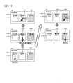
- a first aspect of the present invention is a battery system, which is configured by further connecting a plurality of battery cell groups each having a plurality of battery cells connected in series.
- a plurality of integrated circuits that are provided corresponding to each battery cell group of the battery module and detect and diagnose terminal voltages of each battery cell included in the corresponding battery cell group, and issue commands to the plurality of integrated circuits
- a battery controller that receives detection results and diagnosis results of a plurality of integrated circuits, and the battery system includes a writable nonvolatile memory, and the writable nonvolatile memory includes a maximum of a battery module. Data indicating the usage environment of the battery module including voltage or maximum current and history data based on the usage history of the battery module are maintained. To.
- the history data data representing the state of the battery cell in a state where the cumulative value representing the usage progress of the battery module satisfies the predetermined condition. Is stored data that is not erased and is stored in a storage block that is set in the nonvolatile memory as saved data that is not erased when held in the nonvolatile memory.
- history data data representing the state of the battery cell every time the integrated value of the current of the battery module reaches a predetermined value, It is preferable that the data is not erased and is stored in the nonvolatile memory in addition to the stored data not yet erased.
- the stored data is not erased, and is preferably stored in the nonvolatile memory in addition to the stored data not erased already stored.
- the history data data representing the state of the battery cell every time the integrated value related to the number of operation of the battery module reaches a predetermined value. It is preferable that the data is not erased, and is added to the stored data not erased and stored in the nonvolatile memory.
- the battery system includes a circuit for equalizing the state of charge (SOC) of each battery cell, and as history data It is preferable that the data representing the operation time for making the state of charge (SOC) of the battery cells uniform is stored data that is not erased, and is stored in the nonvolatile memory in the stored data that has not been erased.
- the battery system has a volatile memory, and the nonvolatile memory is stored in the nonvolatile memory at the start of operation.
- Data representing the usage environment and history data that were held are read from the non-volatile memory and written to the volatile memory, the data written to the volatile memory is updated during operation, and is retained in the volatile memory when the operation ends. It is preferable to write and hold the updated data being stored in the nonvolatile memory again.
- data representing the use environment and history data are stored in the storage area of the nonvolatile memory.
- the storage block written later is the second storage block among the first or second storage blocks of the nonvolatile memory.
- the data held in the second block is read, whether the read data is normal, and if the read data is determined normal, It is preferable that the next writing is performed on the first storage block which is different from the storage block from which the data is read out of the first or second storage block. That's right.
- the nonvolatile memory when it is determined that the data read from the second storage block of the nonvolatile memory is abnormal, the nonvolatile memory It is preferable that the next data write is performed on the same second storage block as the block from which the data determined to be abnormal is read. (10) According to the tenth aspect of the present invention, in the battery system according to the eighth aspect, when it is determined that the data read from the second storage block of the nonvolatile memory is abnormal, the nonvolatile memory It is preferable that the new data is written to both the first storage block and the second storage block.
- the third storage block is further set in the nonvolatile memory, and the data is read from the second storage block of the nonvolatile memory.
- the next data is written to the third storage block when the next data is written to the nonvolatile memory, and the next data is read from the nonvolatile memory. It is preferable to read data stored from the third storage block.
- the third storage block is further set in the nonvolatile memory, and the data is read from the second storage block of the nonvolatile memory.
- the terminal voltage of the battery cell is detected when the operation is disclosed, and the variation or deviation of the SOC is obtained from the detected terminal voltage when the operation is disclosed. It is preferable to compare the SOC variation or deviation obtained with the SOC variation or deviation held in the non-volatile memory and determine that the SOC is abnormal when the SOC variation or deviation increases.
- the terminal voltage of the battery cell is detected when the operation is disclosed, and the discharge time for SOC equalization is detected from the detected terminal voltage when the operation is disclosed.
- the obtained discharge time is compared with the discharge time held in the non-volatile memory, and when the discharge time is increased, it is preferable to determine that there is an abnormality.
- the terminal voltage of the battery cell is detected when the operation is disclosed, and the detected battery cell terminal voltage and the battery cell held in the nonvolatile memory It is preferable to determine that the terminal voltage is abnormal when the terminal voltage increases.
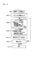
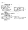
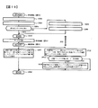
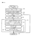
- FIG. 6 is a flowchart for explaining a write operation of a nonvolatile memory.
- 9 is a flowchart for explaining a write operation according to another embodiment.
- 10 is a flowchart for explaining a write operation according to another embodiment.
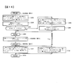
- 1 is a block diagram of a spare storage block according to an embodiment of the present invention.
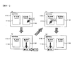
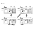
- FIG. 14 is a state transition diagram of the nonvolatile memory for explaining the operation shown in FIG. 13.
- FIG. 14 is a state transition diagram of the nonvolatile memory in the case of data abnormality shown in FIG. 13.
- movement shown in FIG. FIG. 17 is a state transition diagram of the nonvolatile memory for explaining the operation shown in FIG. 16.
- movement shown in FIG. The state transition diagram of the non-volatile memory for demonstrating the operation
- movement shown in FIG. FIG. 20 is a state transition diagram of the nonvolatile memory for explaining the operation shown in FIG. 19.
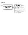
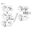
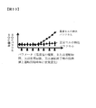
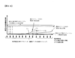
- the block diagram which shows the structure of the battery system provided with two battery modules. When an abnormal battery cell exists in a battery module, the change by the usage progress of a battery module of the operation time for the uniformization of SOC of a battery cell is shown.
- the embodiment described below is not limited to the contents described in the column of the problem to be solved by the above-described invention, the column of means for solving the problem, the column of the effect of the invention, and various other problems. Has been solved and has various effects. Although there are portions that overlap the contents described in the column of the problem to be solved by the above-described invention, the column of means for solving the problem, and the column of the effect of the invention, they are solved by the embodiments described below. Some of the issues and effects are listed below. In the following description of the embodiments, the problems and effects to be solved listed below will be described, and other problems and effects to be solved will be specifically described.
- the lithium battery system mounted in a vehicle as a representative example, it is not restricted to the lithium battery system mounted in a vehicle.
- the above-described invention and the invention having the effects described below can be implemented in a wide field such as a field other than a vehicle, such as an industrial field or a household field.
- the integrated value of the current value of the lithium battery system that is, the integrated value of the output current, the integrated value of the charging current, or the integrated value of both the output current and the charging current is used as a parameter indicating the usage progress.
- the change of the state of each lithium battery cell is detected based on the above parameters, and the phenomenon that leads to the detection or abnormality of the lithium battery cell is obtained from the change of the state. Since the integrated value of the current is used as a parameter, it is possible to improve the detection accuracy of abnormality or deterioration of the lithium battery cell.
- the above current value is always accumulated, and every time the accumulated current value reaches a predetermined value, data relating to the state of the entire lithium battery system or the state of each lithium battery cell is stored. To do. Using the stored data or using newly detected information based on the stored data, an abnormal state relating to the entire lithium battery system or an abnormal state of each lithium battery cell is obtained. Alternatively, the stored data is used, or the information newly detected based on the stored data is used to predict the deterioration state or the life of the lithium battery cell.
- the integrated value of the current value is optimal, but the integrated value of usage time and the number of times of use can be used in addition thereto.
- a use state of a lithium battery system for example, a state where it is mounted on a car
- the lithium battery system is often used repeatedly under substantially the same conditions, and the current value during operation of the lithium battery system often becomes substantially the same value. Therefore, the integrated value of the current of the lithium battery system and the integrated value of the usage time of the lithium battery system often show a correlation. For this reason, the integrated value of usage time can be used as a parameter.
- the integrated value of the number of operations of the lithium battery system can be used as a parameter.
- One of the history data stored based on the above parameters is a variation state of a numerical value (SOC) representing a charging state of each lithium battery cell included in the lithium battery system.
- This history data shows how the numerical value (SOC) variation state has changed based on the usage process indicated by the above parameters, and it is possible to improve the detection accuracy of deterioration and detection of deterioration of lithium battery cells. It becomes.
- the numerical value (SOC) indicating the charge state of each lithium battery cell is close to each other.
- the state of charge (SOC) of each lithium battery cell shows a value different from the value (SOC) representing the state of charge of other lithium battery cells.
- Deteriorated lithium battery cells show a phenomenon in which leakage current increases compared to normal lithium battery cells, and this increase in leakage current is very small, which has been difficult to detect in the past. .
- SOC state of charge
- the deterioration of the lithium battery cell can be detected at an early stage by grasping the phenomenon in which the variation in the state of charge (SOC) with respect to the above parameters or the difference from the average value increases rapidly.
- SOC state of charge
- the variation of the state of charge (SOC) or the future change of the difference from the average value can be estimated, and the life of the battery cell can be predicted.
- control is performed to suppress variation in the state of charge (SOC) of each lithium battery cell and to achieve uniformity.
- SOC state of charge
- SOC state of charge
- Control is performed so as to approach (SOC).
- SOC degree of variation in the state of charge
- the operation time of charge state equalization control can be held as history data, and this value can be used for abnormality detection and deterioration detection of lithium battery cells. Moreover, the lifetime of a lithium battery cell is predictable by estimating the future change with respect to the parameter of the said value.
- the terminal voltage of each lithium battery cell at the end of operation of the battery system is detected to determine the state of charge (SOC) of each lithium battery cell, and the state of charge of each lithium battery cell (SOC) is held in a rewritable nonvolatile memory.
- SOC state of charge
- the terminal voltage of each lithium battery cell is detected to determine the state of charge (SOC) of each lithium battery cell.
- the deviation of each lithium battery with respect to the state of charge (SOC) of the entire lithium battery is stored, it is detected whether the deviation of each lithium battery has changed, and this deviation is based on the change. Detects a lithium battery cell with a unique variation in deviation. By this method, it is possible to detect an abnormal lithium battery cell with higher accuracy.
- the terminal voltage of the lithium battery cell is detected to obtain the state of charge (SOC) of each lithium battery cell, and the state of charge of each lithium battery cell The deviation of (SOC) is obtained.
- SOC state of charge
- the deviation of the state of charge (SOC) of each lithium battery cell from the average state of charge (SOC) of the lithium battery system is used.
- the deviation of the state of charge (SOC) of each lithium battery cell is obtained by calculation and compared with the stored deviation of the state of charge (SOC) of the lithium battery cell.
- the state of change in deviation with respect to the state of charge (SOC) of each lithium battery cell is calculated, and a lithium battery cell having a large change in deviation exceeding the reference value is selected. It can be determined that an abnormal state such as a minute leak has occurred in a lithium battery cell in which the change in deviation exceeds the reference.
- An example of the deviation of each lithium battery to be compared is the deviation at the end of the previous operation and the deviation at the next operation restart.
- the deviation of the state of charge (SOC) of each lithium battery cell at the end of driving of the car is obtained by calculation and held in a writable nonvolatile memory.
- SOC state of charge
- the state of charge (SOC) of each lithium battery cell gradually decreases. Since the leakage current of normal lithium battery cells is very small and the operation stop time is the same for each lithium battery cell, the state of charge (SOC) of each lithium battery cell changes in substantially the same state. The deviation of the state of charge (SOC) of the battery cell hardly changes.
- the leakage current of a lithium battery cell in which an abnormality such as a micro short circuit has occurred is larger than the leakage current of a normal lithium battery cell, and the rate of change of the state of charge (SOC) is large. Therefore, the deviation of the abnormal lithium battery cell becomes larger with the passage of time than the normal lithium battery cell.
- SOC state of charge
- SOC state of charge
- the number of lithium battery cells in which an abnormality has occurred is extremely small among the lithium battery cells included in the battery system. Since most lithium battery cells are normal, the change in the state of charge (SOC) of a normal lithium battery cell and the change in the average state of charge (SOC) of a lithium battery system exhibit very similar characteristics. There is a tendency for the deviation between the abnormal lithium battery cell and the average state of charge (SOC) of the lithium battery system to change markedly. For this reason, the deviation of the state of charge (SOC) of each lithium battery cell is stored in a rewritable nonvolatile memory at the end of the operation of the lithium battery system, and the deviation of the state of charge (SOC) of each lithium battery cell when the operation is resumed. By comparing, it becomes possible to detect a lithium battery cell in an abnormal state such as a micro short circuit that is difficult to find with high accuracy.
- the detection of the state of charge (SOC) of the lithium battery cell described above is optimal at the start of operation or at the time of operation stop for the following reasons from the viewpoint of improving detection accuracy. Therefore, it is desirable to calculate the variation in the state of charge (SOC) of each lithium battery cell by using the state of charge (SOC) detected at the time of starting or stopping the operation. Since the state of charge (SOC) of the lithium battery cell has a correlation with the terminal voltage of the lithium battery cell, the terminal voltage of the lithium battery cell is detected, and the state of charge (SOC) of the lithium battery cell is determined based on the detected terminal voltage. Calculate. However, when the load current is flowing, the correlation between the terminal voltage and the state of charge (SOC) changes due to the influence of an equivalent internal resistance.
- the terminal voltage of each lithium battery cell is measured before the load current supply from the lithium battery system is started in the operation start state. It is desirable to calculate the state of charge (SOC) of each lithium battery cell using the terminal voltage of each lithium battery cell before supplying current to the load, which is the measurement result. Further, it is desirable to measure the terminal voltage of each lithium battery cell and calculate the state of charge (SOC) of each lithium battery cell after the supply of load current from the lithium battery system is stopped in the operation stop state. Of course, even when the operation of the lithium battery system is not started or stopped, the supply of load current is stopped, and the above-described control for equalizing the state of charge of each lithium battery cell is not performed. If so, it is possible to measure the terminal voltage of each lithium battery cell and calculate the state of charge (SOC) of each lithium battery cell.
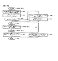
- First and second storage areas (hereinafter referred to as storage blocks) which are at least two storage areas are set in a rewritable nonvolatile memory, and a storage block written after the first or second storage block is provided. If it is the second storage block, the storage data of the second storage block is read, it is determined whether the read storage data is normal, and if the storage data is determined normal, it is updated The next writing of the storage data is performed on the first storage block different from the storage block from which the data is read out of the first or second storage block. Whether the read stored data is normal is determined by a method such as a parity check.
- the storage data is updated based on the storage data of the first storage block, which is another storage block, and at the time of next writing, The updated storage data is written in the second storage block in which the read data is determined to be abnormal.
- the next update storage operation is written last by writing the updated storage data to the second storage block while maintaining the normal data of the first storage block. This can be performed based on the data stored in the second storage block, and the update storage operation can be returned to the normal repetitive operation. Even if an abnormality due to noise or the like temporarily occurs at the time of writing the stored data, the abnormal update storing operation can be minimized and promptly returned to the normal update storing operation. In addition, it is possible to maintain high reliability of the update storage operation while suppressing an increase in memory capacity to be used.
- the history of the use environment data indicating the use state of the lithium battery system, in particular, the lithium battery cell in the nonvolatile memory, and the state change and characteristic change of the lithium battery cell along the course of use. History data representing is stored. These stored data can be taken out and displayed on a display device. If an abnormality occurs, this function enables analysis of the cause of the abnormality, and these data can be used to improve the system for further improving the reliability. In addition, the cause of the failure can be determined accurately and promptly, repair is facilitated, and reliability is improved. Further, by using these stored data for system diagnosis, highly accurate diagnosis is possible. It may not always be appropriate for an ordinary person to read stored data freely, and a system storing stored data has a security function as described in the following embodiments.
- the battery system described in this embodiment is optimal for use as a power supply system mounted on a vehicle, but can also be used in a power supply system for trains or industrial machines.
- a battery system used for an optimal vehicle power supply system will be described as a representative example.
- the term “calculation” is suitable not only for the calculation operation but also for the operation of holding the pre-calculated content in the memory and reading the data stored in the memory, or for the experiment. The value is obtained and stored in the memory, and is used to include an operation of reading the value obtained by the experiment from the memory.
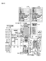
- FIG. 1 is a block diagram showing an example of the configuration of a battery system according to the present invention.
- This battery system includes a battery module 10 in which a plurality of battery cell groups in which a plurality of lithium battery cells (four in this embodiment) are connected in series, and a cell controller (hereinafter abbreviated as C / C). ) 80, battery controller 20, ammeter SA, voltmeter SV.
- C / C cell controller
- the battery controller 20 operates by receiving low voltage power from the low voltage DC power supply 14 mounted on the vehicle, such as a 14 volt power supply.
- the battery controller 20 transmits and receives information to and from the in-vehicle battery system via the transmission path 112 with an external controller 111 including an external host controller.
- the battery module 10 has a plurality of groups GB1,... GBM,... GBN connected in series, and each group has a plurality of lithium battery cells BC1 to BC4 connected in series. .
- each group has four lithium battery cells.
- each terminal voltage of the battery cells BC1 to BC4 constituting each group is detected.
- the number of lithium battery cells included in each group GB1,... GBM,... GBN is determined in consideration of the relationship between the terminal voltage of each lithium battery cell and the withstand voltage of the integrated circuit (hereinafter referred to as IC). Four to six or about ten are desirable.
- the number of lithium battery cells included in the battery module 10 is determined in consideration of the electric power used by the electric load and the voltage supplied to the electric load.
- the number of lithium batteries of the battery modules 10 connected in series is, for example, several tens. From hundreds. By dividing the total number used for the lithium battery module 10 into groups, the number of lithium battery cells constituting each group is determined. An integrated circuit is provided for each group. When the number of lithium battery cells constituting the group increases, the terminal voltage of the group increases, and the voltage applied to the integrated circuit increases.
- the terminal voltage of each lithium battery cell varies depending on the state of charge (SOC) of the lithium battery cell. For example, in the state of charge (SOC) of about 30%, the terminal voltage is about 3.3 volts and the state of charge (SOC) is 70. % Is about 3.8 volts. In the overdischarged state where the battery is discharged beyond the normal operating range, the terminal voltage of the lithium battery cell may be, for example, 2.5 volts or less. In the overcharged state where the battery is charged beyond the normal operating range, the terminal voltage May be 4.2 volts or more.
- the state of charge (SOC) has a correlation with the terminal voltage of the lithium battery cell in the no-load state, and the state of charge (SOC) of each of the lithium battery cells BC1 to BC4 is measured by measuring the terminal voltage. Can be grasped.
- the voltage between the group terminals of the overcharged group is 16.8 volts
- the group is configured by connecting six lithium battery cells in series.
- the voltage between the group terminals of the lithium battery cells is 25.2 volts.
- the number of lithium battery cells constituting the group is increased, it is necessary to increase the withstand voltage of the integrated circuit, and the number of lithium battery cells constituting each group is determined in relation to the withstand voltage of the integrated circuit.
- the number of lithium battery cells constituting each group is four because of the relationship with the withstand voltage of the integrated circuit or for easy measurement of the terminal voltage of each of the battery cells BC1 to BC4. From 6 to 10 at most.
- the group BG1, the group GBL, and the group GBN are respectively configured by battery cells BC1 to BC4, and there are further groups between the group BG1 and the group GBL and between the group GBL and the group GBN. These groups have the same configuration, and are omitted for the sake of simplicity of explanation.
- the cell controller 80 has integrated circuits 3A,... 3L,... 3N corresponding to the groups of lithium battery cells constituting the battery module 10, and each integrated circuit has a terminal voltage of the lithium battery cells constituting the corresponding group. Are respectively provided with voltage detection terminals V1, V2, V3, V4, and GND, and the terminals V1 to V4 to GND of each integrated circuit are connected to each lithium battery cell constituting each group. Each is connected to a positive electrode and a negative electrode.
- the integrated circuits 3A to 3N have transmission / reception terminals (RX, TX, FFI, FFO) for signal transmission.
- the transmission / reception terminals of these integrated circuits are the transmission / reception terminals of the adjacent integrated circuits 3A to 3N, As described below, they are electrically connected in series, and signal transmission between the integrated circuits 3A to 3N and the battery controller 20 is performed via the signal transmission path 112 (see FIG. 1).
- the signal transmission lines By connecting the signal transmission lines in series in this way, the potential of the GND terminal serving as the base of each of the integrated circuits 3A to 3N gradually changes, and the potential difference between the transmission / reception terminals of adjacent integrated circuits is the group of lithium battery cells. Group terminal voltage.
- Each of the integrated circuits 3A to 3N detects the voltage of each of the battery cells BC1 to BC4 constituting the corresponding group GB1 to GBN, and equalizes the state of charge (State of charge) of all the battery cells of all the groups.
- the integrated circuits 3A to 3N have control terminals B1 to B4 for individually adjusting the SOC of the corresponding lithium battery cells BC1 to BC4.
- each of the lithium battery cells BC1 to BC4 is formed in parallel with resistors R1 to R4 for adjusting the state of charge and switch elements 129A to 129B made of semiconductor elements. A series circuit is connected.
- Each of the integrated circuits 3A to 3N conducts the switch elements 129A to 129B of the series circuit connected in parallel with the battery cell having a large charge state, thereby adjusting the holding power of the battery cell having a large charge state for charge state adjustment.
- the state of charge is made uniform by discharging through the resistor.
- the integrated circuits 3A, 3L, and 3N have a function of detecting an abnormal state of each of the lithium battery cells BC1 to BC4 that constitute a corresponding group among the groups GB1 to GBN. These integrated circuits all have the same structure, and each integrated circuit has a terminal voltage measurement circuit, a charge state adjustment circuit, and an abnormal state detection circuit for each battery cell.
- the abnormal state detected by each of the integrated circuits 3A to 3N is an overcharge or overdischarge of a lithium battery cell, an abnormal rise in temperature, or an abnormal internal operation of each integrated circuit. Other abnormalities are detected by the battery controller 20 as will be described later.
- a minute short circuit of the lithium battery cell As typical examples, a minute short circuit of the lithium battery cell, other deterioration inside the lithium battery cell, terminals of each lithium battery, and each of the integrated circuits 3A to 3N Disconnection of the connection circuit and disconnection of the signal transmission path.
- An abnormality determination threshold value of each integrated circuit can be set from the battery controller 20, and an abnormal condition detection condition for each integrated circuit can be determined with an allowable range for an overcharge or overdischarge state of a lithium battery cell. Set. Even if each integrated circuit detects an abnormality of a lithium battery cell, it means that the battery system is in a state that has the above tolerance for the possibility of damage or the like, and has not yet been damaged. Yes.
- the battery controller 20 includes two battery modules 10 and two cell controllers 80. One of them is shown in FIG.
- Signal transmission between the integrated circuits 3A to 3N and the battery controller 20 is performed via an interface including a communication harness 50, an input side interface INT (E), and an outlet side interface INT (O).
- the battery controller 20 Since the battery controller 20 is operated by electric power from the low-voltage DC power supply 14 having the vehicle body of the vehicle as a reference potential, the battery controller 20 operates at a low voltage of 12 V or less, for example, 5 volts, with the vehicle body potential of the vehicle as a reference potential (see FIG. 1).
- each of the integrated circuits 3A to 3N operates with electric power from a corresponding group of lithium battery cells, which is a power supply system different from the above-described vehicle body potential. Are different.
- each of the integrated circuits 3A to 3N detects the terminal voltage of the lithium battery cells constituting the corresponding group in the battery module 10, or discharge control for adjusting the state of charge SOC of the battery cells of the corresponding group, etc. I do. Electric power for performing these operations is supplied from lithium battery cells constituting the corresponding group.
- the reference potential of the integrated circuit is determined based on the potentials of the related groups.
- the GND terminal that is the reference potential of each integrated circuit is connected to the negative terminal of the lithium battery cell that is the lowest potential of each corresponding group, and each integrated circuit is a lithium battery cell that is the lowest potential of the corresponding cell group
- the negative electrode terminal is operated with the reference potential (ground potential) as the reference potential.
- the power supply system of the battery controller 20 and the power supply system of the cell controller 80 are different.
- the communication harness 50 connected to the battery controller 20 needs to be electrically insulated from the serially connected transmission paths 52 and 54 in the integrated circuits 3A to 3N.
- An inlet-side interface INT (E) and an outlet-side interface INT (O) that act as an insulating circuit are provided on the outlet side.
- Each of these interfaces INT (E) and INT (O) uses a photocoupler having a circuit configuration in which an electric signal is once converted into an optical signal and then converted into an electric signal again. Electrical insulation is maintained between the path and the transmission path of the cell controller 80.
- Command information and data information are transmitted from the transmission terminal TX of the battery controller 20, and the transmitted information is received by the reception terminal RX of the integrated circuit 3A via the photocoupler PH1 in the entrance-side interface INT (E).
- Information based on the received information is transmitted from the transmission terminal TX of 3A to the next integrated circuit, and is received by the reception terminal RX of the integrated circuit 3L, and the information transmitted from the transmission terminal TX of the integrated circuit 3L is sequentially transmitted to the integrated circuit. And is received at the reception terminal RX of the integrated circuit 3N, transmitted from the transmission terminal TX of the integrated circuit 3N, and received at the reception terminal RX of the battery controller 20 via the photocoupler PH3 of the exit side interface INT (O). .
- the battery controller 20 receives a measured value and a diagnostic result such as a state of the above or a diagnostic result relating to the connection between each integrated circuit and the battery cell.
- the integrated circuits 3A to 3N have the same structure, and it is necessary to determine the addresses of the integrated circuits 3A to 3N at the first startup of the battery system. If necessary, when the battery controller 20 transmits address assignment command information from the transmission terminal TX, each of the integrated circuits 3A to 3N receives this command information, specifies its own address, and specifies this command information as the adjacent integrated circuit. Send to. By this command information transmission, address assignment is performed in order, instruction information is transmitted to the next integrated circuit, all address assignment is performed, and when the command information returns to the reception terminal RX of the battery controller 20, an address assignment operation is performed. The end of is confirmed. As a result, the circuit structures of the integrated circuits 3A to 3N can be made the same structure, the mass productivity of the correction circuit is improved, and the complexity of wiring is eliminated.
- the integrated circuits 3A to 3N are in a sleep state in order to reduce power consumption.
- the battery controller 20 wakes up each integrated circuit 3A to 3N via this transmission line. Up (Wake Up) command information is sent to automatically transition from the sleep state to the wakeup (Wake Up) state. Accordingly, when the communication command 292 is transmitted from the battery controller 20, each of the integrated circuits 3A to 3N changes from the sleep state to the operation state.
- the transmission path in the battery system forms a loop that is transmitted from the battery controller 20 and returns to the battery controller 20 through the integrated circuits 3A to 3N.
- the information transmitted from the transmission terminal TX of the battery controller 20 returns to the reception terminal RX of the battery controller 20 through the transmission loop again, so that it is possible to confirm whether the command information has been correctly transmitted and the reliability is improved. improves. If an abnormality occurs due to noise or the like during the transmission of command information, the correct command information does not return to the receiving terminal RX of the battery controller 20, so that the occurrence of the abnormality can be easily detected.
- the transmission line may not form a loop shape, and is transmitted from the battery controller 20 to the integrated circuit 3N through the integrated circuit 3A and transmitted by the integrated circuit 3N. The operation may end. Further, although the transmission time becomes longer, the information transmitted to the integrated circuit 3N is not returned from the integrated circuit 3N to the battery controller 20, but is returned to the integrated circuit 3A, and is returned from the integrated circuit 3A to the battery controller 20.
- the transmission time becomes longer, the information transmitted to the integrated circuit 3N is not returned from the integrated circuit 3N to the battery controller 20, but is returned to the integrated circuit 3A, and is returned from the integrated circuit 3A to the battery controller 20.
- Each of the integrated circuits 3A to 3N repeatedly performs diagnosis of the lithium battery cells BC1 to BC4 constituting the corresponding group and diagnosis of its own internal operation at a predetermined cycle, and the diagnosis result is different from the above transmission line, A transmission path for automatically reporting abnormality information at high speed without receiving a command from the battery controller 20 is provided, and 1-bit information indicating the presence or absence of abnormality is transmitted to the battery controller 20 via this transmission path. Is done.
- Switch to This abnormal signal is a 1-bit signal, but the number of bits may be increased.
- the battery controller 20 does not transmit an abnormal signal to each of the integrated circuits 3A to 3N, but it is important to confirm that the abnormal signal transmission path is operating correctly.
- a test signal which is a pseudo-abnormal signal, is transmitted from the terminal FFTEST of the battery controller 20 to check whether the terminal FF pseudo-abnormal signal of the battery controller 20 can be received, thereby diagnosing whether the abnormal signal transmission path is normal. be able to.
- the transmission path of the abnormal signal is connected from the transmission terminal FFTEST of the battery controller 20 to the reception terminal FFI of the integrated circuit 3A via the photocoupler PH2 of the entrance-side interface INT (E), and is not shown from the transmission terminal FFO of the integrated circuit 3A.
- Each integrated circuit is connected to the reception terminal FFI of the integrated circuit 3L. Further, the circuits are sequentially connected in this way, connected to the reception terminal FFI of the integrated circuit 3N, and connected to the reception terminal FF of the battery controller 20 from the transmission terminal FFO via the photocoupler PH4 of the exit side interface INT (O).
- the transmission route of the abnormal signal has a loop shape, the transmission route can be diagnosed by sending and receiving a pseudo abnormal signal from the battery controller 20, and the reliability of the system is improved. Also, as described above, even if there is no transmission command from the battery controller 20, the integrated circuit that has detected the abnormal condition sends an abnormal signal to the next integrated circuit, so that the abnormal condition is promptly transmitted to the battery controller 20. This has the effect of promptly responding to abnormalities.
- the current supplied from the battery module 10 to the load is detected by the ammeter SA, and the battery controller 20 receives the output of the ammeter SA and detects the output current from the battery module 10. Moreover, the terminal voltage of the whole battery module 10 is measured by the voltmeter Vd, and the battery module 10 can detect the total voltage supplied to the load from the output of the voltmeter Vd. It is possible to detect the usage environment of the battery module 10 from these voltmeters and ammeters, and to store the information in a rewritable nonvolatile memory. In particular, by storing the maximum voltage and maximum current in a rewritable nonvolatile memory, the usage environment of the battery module 10 can be verified later.
- the state is Non-volatile storage that is temporarily stored in a volatile memory (hereinafter referred to as RAM) of each integrated circuit built in the battery module 10 or the cell controller 80 described later, and then rewritable based on, for example, a car key switch OFF operation Stored in memory.
- RAM volatile memory
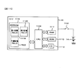
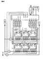
- FIG. 2 is a block diagram of an electronic circuit showing an embodiment of the integrated circuit 3A.
- the integrated circuits 3A to 3N have the same circuit configuration, and the integrated circuit 3A will be described as a representative example.
- the input side terminals V1 to V4 of the integrated circuit 3A are respectively connected to the positive terminals of the lithium battery cells BC1 to BC4 constituting the corresponding group GB1, and the GND terminal is connected to the negative side of the lowest-order lithium battery BC4.
- Terminal voltages of the lithium battery cells BC1 to BC4 are input to the selection circuit 120 via the input terminals V1 to V4 and GND, respectively.
- the selection circuit 120 includes a multiplexer and includes switches 120A to 120E. By switching the connections of the switches 120A to 120E in a predetermined order, the terminal voltages of the lithium battery cells BC1 to BC4 are input to the voltage detection circuit 122 and converted into digital values by the voltage detection circuit 122.
- the terminal voltage of the corresponding group GB1 is input to the input terminal V1 and GND of the integrated circuit 3A, and the terminal voltage of this group GB1 is supplied to the power supply circuit 121.
- the power supply circuit 121 includes a DC / DC converter or the like, converts the supplied voltage into a predetermined constant voltage, and supplies this constant voltage as a power supply voltage to each circuit in the integrated circuit 3A. Further, it is supplied as a comparison reference voltage to an analog comparison circuit for judging the state.
- the power management circuit 124 is configured to manage the state of the power circuit 121.
- Each terminal voltage of the cell group GB1 converted into a digital value by the voltage detection circuit 122 is input to the IC control circuit 123 and held in the internal storage circuit 125.
- the IC control circuit 123 includes an arithmetic circuit, a storage circuit 125, a power management circuit 124, and a timing control circuit 252 for periodically detecting various voltages and performing state diagnosis.
- the storage circuit 125 includes, for example, a volatile memory (RAM) composed of a register circuit and a rewritable nonvolatile memory, and each terminal of each of the lithium battery cells BC1 to BC4 detected by the voltage detector 122. The voltage is stored in association with each of the lithium battery cells BC1 to BC4, and other detection values are held so as to be readable at a predetermined address.
- RAM volatile memory
- the integrated circuit temporarily stores the above measured values and diagnosis results from an abnormality determination circuit 131 (to be described later) in a volatile memory RAM, and further writes the contents in a rewritable nonvolatile memory such as an EEPROM, and holds these data. To do.
- the rewritable nonvolatile memory stores data representing the usage environment of the corresponding group of lithium battery cells BC1 to BC4, and history data based on parameters representing the usage history. These storage methods will be described later.
- the data representing the usage environment includes, for example, the maximum terminal voltage and minimum terminal voltage of each lithium cell, the maximum temperature, the usage time, and the number of uses.
- the history data includes various data at the end of the previous operation, terminal voltage of each lithium cell based on the above parameters, charge state SOC, charge state deviation, and the like.
- the IC control circuit 123, the volatile memory, or the rewritable nonvolatile memory is connected to a communication circuit 127 and transmitted to the battery controller 20 via the communication circuit 127.
- the integrated circuit 3A includes a communication circuit 127 for transmitting and receiving signals such as commands and data and its input / output terminals.
- a communication command is received at the RX terminal from the battery controller 20 via the photocoupler PH1 of the inlet side interface INT (E).
- the communication command is sent from the communication circuit 127 to the IC control circuit 123, where the content of the communication command is decoded and processing according to the content of the communication command is performed.
- the communication command includes a communication command for requesting a measurement value of the terminal voltage of each of the lithium battery cells BC1 to BC4 to the integrated circuit 3A, and a discharge operation for adjusting the charge state of each of the battery cells BC1 to BC4.
- the integrated circuit 3A further includes an instruction for reporting the storage contents of the volatile memory and an instruction for reporting the storage contents of the rewritable nonvolatile memory.
- the positive terminal of the lithium battery cell BC1 is connected to the input terminal B1 through the resistor R1, and this input terminal B1 is connected to one terminal of the operation state detection circuit 128A of the balancing switch 129A, and the operation of the switch 129A.
- the other input terminal of the state detection circuit 128A is connected to the negative terminal of the battery cell BC1 via the terminal V2.
- a series circuit of the resistor R1 and the balancing switch 129A is connected between the terminals of the lithium battery cell BC1.
- the balancing switch 129A is controlled to be opened and closed by the discharge control circuit 132.
- the positive terminal of the lithium battery cell BC2 is connected to the input terminal B2 via the resistor R2, and this input terminal B2 is connected to one terminal of the operation state detection circuit 128B of the balancing switch 129B.
- the other terminal of the operation state detection circuit 128B is connected to the negative terminal of the lithium battery cell BC2 via the terminal V3.
- a series circuit of the resistor R2 and the balancing switch 129B is connected between the terminals of the lithium battery cell B2.
- the balancing switch 129B is controlled to be opened and closed by the discharge control circuit 132.
- the positive terminal of the lithium battery cell BC3 is connected to the input terminal B3 via the resistor R3, and this terminal B3 is connected to one terminal of the operation state detection circuit 128C of the balancing switch 129C.
- the other terminal of the operation state detection circuit 128C is connected to the negative terminal of the lithium battery cell BC3 via the terminal V4.
- a series circuit of the resistor R3 and the balancing switch 129C is connected between the terminals of the lithium battery cell BC3.
- the balancing switch 129C is controlled to open and close by the discharge control circuit 132.
- the positive terminal of the lithium battery cell BC4 is connected to the input terminal B4 via the resistor R4, and this input terminal B4 is connected to one terminal of the operation state detection circuit 128D of the balancing switch 129D, and the operation state of the switch
- the other terminal of the detection circuit 128D is connected to the negative terminal of the lithium battery cell BC4 via the terminal GND.
- a series circuit of the resistor R4 and the balancing switch 129D is connected between the terminals of the battery cell BC4.
- the balancing switch 129D is controlled to be opened and closed by the discharge control circuit 132.
- the operation state detection circuits 128A to 128D of the balancing switches 129A to 129D repeatedly detect voltages at both ends of the balancing switches 129A to 129D at a predetermined period, respectively, and detect whether or not the balancing switches 129A to 129D are normal.
- the balancing switches 129A to 129D are switches for adjusting the charging state of the battery cells BC1 to BC4. If these switches are abnormal, the charging state of each battery cell cannot be controlled, and the battery cell is overcharged or overdischarged. There is a fear.
- each balancing switch 129A to 129D is, for example, a case where the terminal voltage of the corresponding balancing switch indicates the terminal voltage of the battery cell regardless of the state where a certain balancing switch is conductive. In this case, this balancing switch is not in a conductive state based on the control signal. On the other hand, when the control signal of a certain balancing switch is to open the balancing switch, the terminal voltage of the corresponding balancing switch is lower than the terminal voltage of the battery cell. This balancing switch is conducted regardless of this control signal.
- a voltage detection circuit constituted by a differential amplifier or the like is used, and is compared with a predetermined voltage for performing the above determination by an abnormality determination circuit 131 described later.
- Balancing switches 129A to 129D are composed of, for example, MOS FETs, and discharge the electric power stored in the corresponding lithium battery cells BC1 to BC4 by closing the switches.
- An electric load such as an inverter is connected to the battery module 10 in which a large number of battery cells are connected in series, and supply of current to these electric loads is performed by the entire number of battery cells connected in series. Further, in the regenerative state where the battery module 10 is charged, for example, the regenerative current is supplied from the electric load to the whole of a large number of battery cells connected in series. The supply of current from a number of batteries connected in series is limited by the state of the battery cell that is the most discharged among the battery cells, that is, the battery cell having the lowest SOC.
- the balancing switch 129 connected to this battery cell is turned on and connected in series. A discharge current is passed through the resistor. As a result, the state of charge of the battery cells connected in series is controlled to be in the same direction.
- the battery cell in the most discharged state is used as a reference cell, and other battery cells are discharged based on a difference from the reference cell.
- the state of charge of each battery cell can be obtained by calculation based on the terminal voltage of the battery cell. Since the charge state of the battery cell and the terminal voltage of the battery cell have a correlation, the charge state of the battery cell is controlled by controlling the opening / closing of the balancing switch 129 so that the terminal voltage of each battery cell is approximately the same. It can be about the same.
- the abnormality determination circuit 131 is based on the control signal from the IC control circuit 123, and is a terminal of the balancing switch 129 to be diagnosed that is a signal from the potential conversion circuit 130. The voltage is compared with a determination voltage to determine whether each of the balancing switches 129A1 to 129D is abnormal.
- the IC control circuit 123 Based on the command from the battery controller 20 sent to each integrated circuit, the IC control circuit 123 sends a command signal for turning on the balancing switch 129 corresponding to the battery cell to be discharged to the discharge control circuit 132. Based on this command signal, the discharge control circuit 132 adds a gate voltage for conducting the balancing switches 129A to 129D made of MOS FETs, and executes the conducting operation.
- the balancing switch 129A to 129D When abnormality of the balancing switches 129A to 129D is detected in the abnormality determining circuit 131, the balancing switch 129A to 129D is specified by the signal from the discharge control circuit 132, and the information is the IC control circuit. It is output to 123. Further, the detected abnormal signal is held in a volatile memory RAM in the integrated circuit. The IC control circuit 123 outputs the abnormality of the balancing switches 129A to 129D from the 1-bit transmission terminal FFO of the communication circuit 127 and sends it to the communication circuit 127 of the next integrated circuit. It is sent to the controller 20.
- the IC control circuit 123 sends the abnormality of the balancing switches 129A to 129D and information for identifying the abnormal balancing switch to the battery controller via the transmission terminal TX of the communication circuit 127. 20 to send.
- the battery controller 20 temporarily holds the received abnormality signal in the volatile memory RAM inside the battery controller 20.
- Data indicating measurement values and diagnosis results held in the volatile memory RAM of the integrated circuit or the battery controller 20 is held in a rewritable nonvolatile memory (EEPROM). For example, the holding timing is appropriate when the car key switch is OFF.
- FIG. 3 is an explanatory diagram showing a method for transmitting and receiving signals between the integrated circuits 3A to 3N.
- FIG. 3A shows a signal 3A-RX received by the terminal RX of the integrated circuit 3A, a signal 3A-TX transmitted from the terminal TX of the integrated circuit 3A, and a signal 3B received by the terminal RX of the next integrated circuit 3B.
- -RX and the signal 3B-TX transmitted from the terminal TX of the next integrated circuit 3B, and also the signal 3C-RX received by the terminal RX of the next integrated circuit 3C and the signal transmitted from the terminal TX of the integrated circuit 3C 3C-TX is shown.
- the signal 3A-TX is divided by the resistor RA in the integrated circuit 3A and the resistor RB in the integrated circuit 3B to form a signal 3B-RX, and the signal 3B-TX is combined with the resistor RB 'in the integrated circuit 3B.
- the signal 3C-RX is formed by dividing by the resistor RC in 3C. Thereafter, the voltage of the received signal is determined by dividing the voltage by the resistors in the integrated circuit in the communication paths connected in series.
- FIG. 3B shows the potential levels of the signals 3A-RX, 3A-TX, 3B-RX, 3B-TX, 3C-RX, and 3C-TX.
- the threshold voltage is set to an intermediate voltage between the addition voltage for the four battery cells and the addition voltage for the two battery cells toward the downstream group from the highest group GB1 of the voltage level. Like to do. The reason for this is that when the signal from the TX terminal of the integrated circuit 3A is determined with the same threshold as that of the integrated circuit 3A on the basis of each voltage of the battery cell managed by the integrated circuit 3B, the low level of the signal This is to avoid the inconvenience that becomes 1/2 of the total voltage applied to the integrated circuit 3B.
- the signal level has been described on the premise of transmission from the high potential side to the low potential side, but transmission from the low potential side to the high potential side is also possible by performing level shift by resistance division.
- FIG. 4 is a diagram for explaining the timing of the measurement operation.
- Each of the integrated circuits 3A to 3N has a function of performing a diagnostic operation together with the measurement operation.
- the integrated circuit 3A to 3N repeatedly performs measurement at the operation timing shown in FIG. 4, and the diagnosis is executed in synchronization with the measurement.
- FIG. 6 shows a detailed circuit of the selection circuit 120, the voltage detection circuit 122, and the memory circuit 125 for holding the detected voltage shown in FIG. 2, a detailed circuit for performing diagnosis, and further according to the present invention.
- a volatile memory RAM 1107 for temporarily storing important diagnostic results and measurement results and a rewritable nonvolatile memory (EEPROM) 1106 are shown.
- each group constituting the battery module 10 has four lithium battery cells.
- the integrated circuits shown in FIGS. 4 to 6 are circuits that can handle six battery cells. Therefore, in the embodiment of FIGS. 1 and 2, each group constituting the battery module 10 includes four lithium battery cells, but the number of lithium battery cells constituting each group is increased to six. It is possible to increase the number of lithium battery cells in the same way. The number of lithium battery cells that constitute each group is determined by the total number of lithium battery cells, the processing speed of measurement and diagnosis, and the like.
- FIG. 4 is a diagram for explaining the timing of the measurement operation.
- the timing and measurement cycle of the measurement operation or the diagnosis operation are managed by a start circuit 254 and a stage counter including a first stage counter 256 and a second stage counter 258.
- the stage counter may be a normal counter or a shift register. In the case of a shift register, the number of stages is the number of types of stages, which is 10 in this embodiment.
- the startup circuit 254 receives (1) a communication command for requesting Wake Up sent from the transmission line at the terminal RX, or (2) when the supply of the power supply voltage of the integrated circuit reaches a predetermined voltage (3 ) Or a signal indicating that the starter switch (key switch) of the car is turned on, a reset signal is output to the first and second stage counters to initialize the stage counters 256 and 258, and The operation of outputting a clock signal at a predetermined frequency is performed. Accordingly, when one of the above conditions (1) to (3) is satisfied, each integrated circuit executes a measurement operation and a diagnosis operation. On the other hand, when the communication command 292 requesting the sleep is received from the transmission path 112 (see FIG.
- the start circuit 254 returns the timing when the stage counter returns to the reset state, that is, the initial state. Then, stop the clock output. Since the progress of the stage is stopped by stopping the output of the clock, the execution of the measurement operation and the diagnosis operation is stopped.
- the first stage counter 256 receives the clock signal from the activation circuit 254, outputs a count value for controlling the processing timing in each stage, and generates a timing signal STG1 for controlling the processing timing in the stage by the decoder 257.
- the count value of the second stage counter 258 corresponds to the type of stage shown in the row 260Y1 of the operation table 260, and the corresponding stage switches from left to right in the row 260Y1 of the operation table 260 as the count value advances.
- a stage signal STG2 specifying each stage is output from the decoder 259.
- the first stage counter 256 and the second stage counter 258 are in the reset state, that is, the second stage counter 258 has a count value that identifies the stage STGCal, and the stage signal STG2 that is the output of the decoder 259 is the stage. This signal is used to select STGCal.
- the processing in the stage is performed, and when the counting of the second stage counter 258 advances by one, the count content of the second stage counter 258 is the row 260Y1 of the operation table 260.
- a value indicating STGCV1, which is the stage in the second column from the left, and a stage signal STG2, which is an output of the decoder 259, is a signal indicating STGCV1.
- stage STGCV1 measurement and diagnosis of the battery cell BC1 are performed.
- the stage described in the column of the row 260Y1 of the operation table 260 switches from left to right.
- Measurement and diagnosis of the battery cell BC1 are performed at the stage STGCV1
- measurement and diagnosis of the battery cell B2 are performed at the next stage STGCV2
- measurement and diagnosis of the battery cell B3 are performed at the next stage STGCV3, and the next stage STGCV4
- measurement and diagnosis of the battery cell BC4 are performed.
- the stage STGCV5 and the stage STGCV6 are not used or skipped so that the stage STGCV5 and the stage STGCV6 are not exist. Details of this operation will be described later. Therefore, the next stage STGCV4 is followed by a stage STGVDD for measuring and diagnosing the output of the power supply circuit 121 in the integrated circuit, and the next stage is a stage STGTEM for measuring and diagnosing the output of the temperature sensor. Next is a stage STG reference power supply that measures and diagnoses the reference voltage used in the integrated circuit.
- the count value of the second stage counter 258 After the stage STG reference power supply, the count value of the second stage counter 258 returns to the initial state and again becomes a value corresponding to the stage STGCal, so that the output signal STG2 of the decoder 259 becomes a signal specifying the stage STGCal again.
- each stage in the row 260Y1 of the operation table 260 is executed from left to right, and this is repeated. If the content of the second stage counter 258 is forcibly set to a specific value, the stage process corresponding to that value is executed. The processing contents in each stage will be described in detail later.
- the execution contents of the diagnosis operation and the measurement operation are selected depending on whether the number of lithium battery cells constituting each group to which the integrated circuit corresponds is four or six.
- a specific circuit is shown in FIG.
- the first stage counter 256 repeats the counting operation based on the clock signal from the starting circuit 254, and when the first stage counter 256 reaches a predetermined count value, the count value of the second stage counter 258 advances by one.
- FIG. 5 shows a configuration example of the second stage counter 258.
- the second stage counter 258 is composed of ten registers.
- the initial state only the shift circuit 1 is in the state 1, the other shift circuits 2 to 10 are in the state zero, and the output STG2 of the decoder 259 outputs the stage signal STGCal.
- the count value of the first stage counter 256 reaches a predetermined value, the state 1 is shifted to the next shift circuit 1, and the shift circuit 1 and the shift circuits 3 to 10 become the state zero.
- the decoder 259 outputs the stage signal STGCV4.
- stage signal STGCV5 and stage signal STGCV6 corresponding to shift circuit 6 and shift circuit 7 are not output from decoder 259, and stage signal STGVDD is output from decoder 259 after stage signal STGCV4.
- Measurement and diagnosis are roughly divided into two types. One of them is measurement as a sensor and diagnosis of whether or not the measurement target is in an abnormal state, and the measurement schedule is described in line 260Y2.
- the other one of the two types is a control device including an integrated circuit, that is, the measurement system shown in FIG. 2 or a diagnosis of the diagnosis circuit itself along with this measurement system. included.
- the measurement operation is divided into two parts according to the passage of time.
- the diagnosis of the measurement object is the first half part, the part described as RES, and the self-diagnosis is the part described as the first half RES, and the part described as the measurement of the second half part.
- the diagnosis of each battery cell accompanying a measurement and a measurement result is performed.
- the first half RES of each stage not only performs self-diagnosis, but also initializes the analog-digital converter 122A used for measurement.
- the integration type analog-digital converter 122A using a capacitor is used in order to reduce the influence of noise.
- the discharge of the charge stored in the capacitor during the previous operation is also performed at the timing of the first half RES. carry out.
- the measurement using the analog-digital converter 122A is executed and the measurement target is diagnosed based on the measured value.
- the stage STGCal mainly performs self-diagnosis shown in rows 260Y3 to 260Y9.
- the diagnosis of the selection circuit 120 itself which is a multiplexer described in the row 260Y6, and the selection circuit 120 described in row 260Y7 are switched.
- Diagnosis of the switching circuit that performs the operation, and diagnosis of the selection signal of the part that performs the digital comparison operation inside the integrated circuit which is an item described in the row 260Y9 (selection of the current value storage circuit 274 and the reference value storage circuit 278 in FIG. 6) Signal).
- Stages STGCV1 to STGCV6 are stages for measuring terminal voltages of battery cells in order and diagnosing whether each battery cell is in an overcharge or overdischarge state from the measured values. Since an overcharge or overdischarge state actually causes a failure of the battery system, the diagnosis of overcharge or overdischarge is set with a safety margin.
- the stage STGCV5 and the stage STGCV6 are skipped as described in FIG.
- stage STGVDD the output voltage of the power supply circuit 121 is measured
- stage STGTEM the output voltage of the thermometer is measured.
- stage STGTEM it is diagnosed whether the analog circuit, analog-digital converter, and reference voltage generation circuit inside the integrated circuit, which are diagnostic items described in the row 260Y4, are normalized.
- the voltage output from the reference voltage generation circuit is a known voltage value. If the measurement result of the voltage value is not within the predetermined range, it can be determined that one of the circuits is abnormal, and the control is executed correctly. You can diagnose whether you can.
- FIG. 6 shows a measurement circuit, a diagnostic circuit, and a memory circuit in each of the integrated circuits 3A to 3N.
- a measurement operation of the terminal voltage of each battery cell of the group GB1 of the battery module 10 by the integrated circuit 3A will be described.
- the selection circuit 120 selects the terminal V1 and the terminal V2, and by this selection, the terminal voltage of the battery cell BC1 shown in FIGS. 1 and 2 is output from the selection circuit 120 to the voltage detection circuit 122. Is done.
- the voltage detection circuit 122 includes a differential amplifier 262 and an analog-digital converter 122A.
- the differential amplifier 262 includes an operational amplifier 122OP and resistors 122R1 to 122R4.
- the differential amplifier 262 has a function of adjusting different potentials, that is, a function of level shift, and generates an analog output based on a voltage difference between two selected input terminals regardless of the base potential of each input terminal. As a result, the influence of the potential difference on the difference in the reference potential between the lithium battery cells connected in series is removed, and an analog output based on the terminal voltage of the lithium battery cell BC1 is obtained.
- the output of the differential amplifier 262 is digitally converted by the analog-digital converter 122A and output to the averaging circuit 264.
- An average value of the measurement results of a predetermined number of times is obtained by the averaging circuit, and when the average value is the lithium battery cell BC1, it is held in BC1 of the current value storage circuit 274.
- the average value circuit 264 calculates the average value of the number of measurements held in the averaging control circuit and holds the output in the above-described current value storage circuit 274. If 1 is commanded to the averaging control circuit, the output of the analog-digital converter 122A is not averaged and is held in BC1 of the current value storage circuit 274 as it is.
- the four measurement results of the terminal voltage of the battery cell BC1 are averaged and held in BC1 of the current value storage circuit 274.
- the averaging operation of the averaging circuit 264 can be performed for each measurement.
- the adverse effects of noise can be eliminated by averaging the measurement results by a predetermined number of times.
- the DC power of the battery module 9 shown in FIG. 1 is supplied to the inverter device and converted into AC power.
- the inverter device converts DC power to AC power, current conduction and interruption are performed at high speed. A large noise is generated by the current conduction or interruption operation.
- the averaging circuit has the effect of reducing the adverse effects of such noise.
- the digital value of the terminal voltage of the battery cell BC1 after digital conversion is held in the register BC1 of the current value storage circuit 274.
- the measurement operation is performed within the time shown as the measurement of the stage STGCV1 in FIG.
- the diagnostic operation is continuously performed within the time indicated as the measurement of the stage STGCV1.
- the diagnostic operation includes overcharge diagnosis and overdischarge diagnosis.
- the digital value of the terminal voltage of the battery cell BC1 is held in the register BC1 of the current value storage circuit 274, and then the digital multiplexer 272 is transferred from the register BC1 of the current value storage circuit 274 based on the stage signal stages STGCV1 and STG1.
- the terminal voltage of BC1 is read and sent to the digital comparator 270.
- the digital multiplexer 276 reads the overcharge determination reference value OC from the reference value storage circuit 278 and sends it to the digital comparator 270.
- the digital comparator 270 compares the terminal voltage of the battery cell BC1 from the register BC1 with the determination reference value OC of the overcharge, and if the terminal voltage of the battery cell BC1 is greater than the determination reference value OC of the overcharge. Then, a flag diagnosis flag indicating abnormality is set in the flag storage circuit 284. Also set OCflag. In practice, control is performed so that an overcharge state does not occur, and such a state hardly occurs. However, if it occurs, it is very dangerous and the diagnosis is performed repeatedly.
- the abnormality flag set in the flag storage circuit 284 is then sent to the volatile memory RAM and the number of abnormalities is added.
- the value of the flag storage circuit 284 is held in the diagnosis result item as a past history, and in particular, regarding the abnormality in the battery cell, it is held in the battery information column.
- the digital multiplexer 272 reads the terminal voltage of the battery cell BC 1 from the register BC 1 of the current value storage circuit 274 and sends it to the digital comparator 270.
- the digital multiplexer 276 reads the overdischarge determination reference value OD from the reference value storage circuit 278 and sends it to the digital comparator 270.
- the digital comparator 270 compares the terminal voltage of the battery cell BC1 from the register BC1 with the overdischarge determination reference value OD, and if the terminal voltage of the battery cell BC1 is smaller than the overdischarge determination reference value OD. Then, a flag [diagnosis flag] indicating an abnormality is set in the flag storage circuit 284.
- [ODflag] is also set. As in the case of the overdischarge described above, control is actually performed so that an overdischarge state does not occur, and such an overdischarge state hardly occurs. However, if it occurs, it will cause a failure of the battery system, so the diagnosis is repeated.
- the diagnosis result is not only held in the flag storage circuit 284 but also held as history data in the diagnosis result item of the history data item in the volatile memory 1107.
- the history data of the volatile memory 1107 holds various conditions of the lithium battery cell when an abnormality occurs. Further, the current number of times 1 is added to the past value of the number of occurrences of abnormality and the numerical value is held.
- the selection circuit 120 in FIG. 6 selects the terminal voltage of the battery cell BC2 and outputs it to the voltage detection circuit 122.
- the voltage detection circuit 122 performs digital conversion, calculates an average value in the averaging circuit 264, and holds it in the register BC2 of the current value storage circuit 274.
- the terminal voltage of the battery cell BC2 read from the register BC2 by the digital multiplexer 272 is compared with the overcharge determination reference value OC, and then the terminal voltage of the battery cell BC2 is compared with the overdischarge determination reference value OD. .
- the abnormal state is determined by comparison with the overcharge determination reference value OC or the overdischarge determination reference value OD. If it is abnormal, a flag [diagnostic flag] indicating abnormality is set in the flag storage circuit 284, and [OCflag] or [ODflag] that is the cause of the abnormality is set.
- the terminal voltage of the battery cell BC3 is measured at the stage STGCV3 in FIG. 4, and overcharge and overdischarge are diagnosed.
- the terminal voltage of battery cell BC4 is measured and overcharge or overdischarge is diagnosed.
- the diagnosis history and the diagnosis result are further held in the volatile memory 1107.
- the averaging circuit 264 averages the measurement values. Is calculated.
- the calculation result is first held in the current value storage circuit 274.
- Each integrated circuit independently performs measurement measurement and calculation of the average value of the measurement results for all the battery cells of the group to which the integrated circuit is related, and registers BC1 of the current value storage circuit 274 of each integrated circuit. Hold in register BC6.
- the volatile memory 1107 stores the following information (1) to information (5).
- Information (1) is a gain of the voltmeter SV and a voltage offset that is an error of the voltmeter SV, a gain of the ammeter SA and a current offset that is an error of the ammeter SA, or correction data of the analog-digital converter.
- Information (1) is correction data used to improve the measurement accuracy of each of the integrated circuits 3A to 3N.
- Information (2) is the diagnosis result of the lithium battery cell and the integrated circuit itself, and the information is information such as the number of diagnosis for each item and the number of abnormal cases for each item, or variation in the charging rate of lithium battery cells BC1 to BC4 described later. That is, the history data of the lithium battery module or lithium battery cell.
- Information (3) is information regarding the usage environment of the lithium battery.
- Information (4) is information on the target product, for example, information on a vehicle to be mounted.
- Information (5) is security information that protects stored data from a third party.
- the above information (1) to (5) is information that may be retained by the battery controller 20 even if it is not retained in each integrated circuit. However, if the battery controller 20 is removed for some reason, or the battery controller 20 In the present embodiment, not only the battery controller 20 but also each integrated circuit holds it.
- Each of the integrated circuits 3A to 3N has a rewritable nonvolatile memory 1106, and by holding information (1) relating to correction specific to each integrated circuit, for example, by holding a correction value related to the voltage detection circuit 122, Detection accuracy and diagnostic accuracy can be improved.
- information (1) relating to correction specific to each integrated circuit, for example, by holding a correction value related to the voltage detection circuit 122.
- Detection accuracy and diagnostic accuracy can be improved.
- various electrical characteristics change due to the influence of temperature, which is an obstacle to improving diagnostic accuracy. If not only the correction of the voltage detection circuit 122 but also the characteristic change of the detection and diagnosis target can be corrected, the detection accuracy and diagnosis accuracy can be improved.
- Information (2) will be described later.
- Information (3) is information for knowing the usage environment of the lithium battery cell, and how much the battery is used in a state exceeding a certain standard, and the maximum terminal voltage and the minimum terminal voltage are also held. In addition, the maximum load current and the maximum charging current are also maintained. The maximum load current and the maximum charging current are values that cannot be detected by the integrated circuit, and these values are sent from the battery controller 20. On the other hand, the maximum terminal voltage and the minimum terminal voltage for each battery cell are detected by the integrated circuit, and the result is held by the integrated circuit, sent to the battery controller 20, and also held by the battery controller 20. Further, the temperature of the battery module 10 is also stored as a history.
- the information on the target product in information (4) is, for example, the type and version information of the vehicle to be mounted, and further information on the destination to be used. Reading this information reveals the vehicle on which this battery system is mounted. Therefore, mounting errors during maintenance can be prevented.
- This information is commonly used for the battery controller 20 and is not so important information in each integrated circuit, but is stored as a backup of the battery controller 20.
- the security information of information (5) is used when reading and writing stored information. By providing security information during maintenance, it is possible to prevent other information from being written by mistake.
- substantially the same information is held in the battery controller 20, but different information may be held.
- the integrated circuit that controls the battery cell may not have the information holding function, and only the battery controller 20 may hold the data.
- the integrated contents for controlling the battery cells and the battery controller 20 may store the stored contents separately in relation to the respective information.
- an integrated circuit that controls battery cells may be specialized in measurement results and diagnosis results for each corresponding group. If it does in this way, about each battery cell which constitutes battery module 10, the past use state can be held as a history, and the above-mentioned history can be used for analysis etc.
- FIG. 7 is a circuit diagram of a power supply system 1 for a rotating electrical machine for a vehicle using the battery system shown in FIG. 1 as a direct current power source for rotating electric power for a hybrid vehicle or an electric vehicle. It is a rotating electrical machine used for In the power supply system 1 shown in FIG. 7, the battery module 10 described in FIG. 1 uses two sets of a high-potential side battery module 10A and a low-potential side battery module 10B, each composed of lithium battery cells connected in series. Has been.
- the high potential side battery module 10 ⁇ / b> A and the low potential side battery module 10 ⁇ / b> B are connected in series via the cutoff switch 6.
- the disconnect switch 6 is a service disconnect switch (hereinafter referred to as an SD switch) provided for safety during maintenance and inspection.
- the SD switch 6 is opened before the metal case covering the outside of the power supply system 1 is opened. This metal case can be opened by opening 6.
- the positive terminal of the high potential side battery module 10A is connected to the positive terminal of the inverter device 220 via the positive high voltage cable 81 and the relay RLP. Further, the negative electrode terminal of the low potential side battery module 10B is connected to the negative electrode terminal of the inverter device 220 via the negative high voltage cable 82 and the relay RLN.
- the high-potential side battery module 10A and the low-potential side battery module 10B are connected in series via an SD switch 6.
- a high-voltage battery having a nominal voltage of 340V and a capacity of 5.5Ah (a power source in which two battery modules 10 are connected in series) The battery of the system 1).
- the SD switch 6 is provided with a fuse as well as a mechanical disconnecting machine, and has a rated current of about 125 A, for example. As described above, since the SD switch 6 is always opened at the time of maintenance and inspection work, an electric shock can be prevented because a closed circuit is not formed even if the operator's body touches only one of the positive high voltage cable 81 and the negative high voltage cable 82. For this reason, high safety can be maintained.
- the relay RLN is provided between the negative electrode terminal of the low-potential side battery module 10B and the inverter device 220, and the current flows between the positive electrode terminal of the high-potential side battery module 10A and the positive electrode terminal of the inverter device 220.
- Two ammeters SA1 and SA2 and a relay RLP which act as a total SA are provided.
- a series circuit of a resistor RPRE and a precharge relay RLPRE is connected in parallel with the relay RLP.
- the ammeter SA1 is provided between the positive terminal of the high potential battery module 10A and the positive main relay RLP
- the ammeter SA2 is provided between the positive main relay RLP and the inverter device 220.
- the output lines of the ammeters SA1 and SA2 are led to the battery controller 20, and the amount of current supplied from the lithium battery system can be monitored by the ammeters SA1 and SA2.
- the values of the ammeter SA1 and the ammeter SA2 should be the same value. However, when an abnormality such as electric leakage occurs, the values of the ammeter SA1 and the ammeter SA2 are different. Therefore, this configuration can detect the occurrence of abnormality such as electric leakage. Further, if the relay RLP and the relay RLN are operating normally, the outputs of the ammeters SA1 and SA2 should change according to the conduction and interruption of the relay RLP and the relay RLN. By monitoring the operation and the measured values of the ammeters SA1 and SA2, the operation of the relay and the measurement function of the ammeter can be diagnosed.
- the errors of the ammeters SA1 and SA2 are measured in advance before shipment, and the error correction value is stored before shipment.
- Data shown in FIG. 8 is stored in the rewritable nonvolatile memory 1116 included in the battery controller 20, and the data D5 of the KD1 file of the stored data is gain information and offset information of the ammeters SA1 and SA2. 8 is read as it is into the volatile memory 1117 when the operation of the power supply system 1 is started, and similar data is held in the volatile memory 1117.
- the outputs of the ammeters SA1 and SA2 are taken into the battery controller 20, corrected based on the ammeter gain information and offset information stored in the volatile memory RAM of the battery controller 20, and improved in the accuracy of the measured current value.
- the power output from the high potential battery module 10A or the low potential battery module 10B or the power to be charged is calculated.
- These calculation results are written as battery information in a volatile memory (ROM) 1117 of the battery controller 20 and then stored in a rewritable nonvolatile memory (EEPROM) 1116.
- ROM volatile memory
- EEPROM rewritable nonvolatile memory
- the value exceeding the predetermined standard and the highest price are stored separately for each item.
- the currents measured by the ammeters SA1 and SA2 are integrated and held in the storage area of the data D11 of the file KD2 and the data D35 of the file KD3 in FIG.
- the output power or charging power of each battery cell constituting the high potential battery module 10A and the low potential battery module 10B is calculated from the terminal voltage of each lithium battery cell.
- the calculated result is obtained by changing the volatile memory 1107 of each integrated circuit corresponding to the battery cell, the rewritable nonvolatile memory 1107 (see FIG. 6), the volatile memory 1117 of the battery controller 20 or the rewritable memory. It is held in the nonvolatile memory 1116 (see FIG. 7).
- the inverter control circuit 222 receives a motor control command from the external controller 111, and in order to start driving the motor 230, the negative-side relay RLN is changed from the open state to the closed state, and then the precharge relay RLPRE is opened. Then, the smoothing capacitor 228 is charged, and then the positive-side relay RLP is changed from the open state to the closed state, and the supply of power from the lithium battery system of the power supply system 1 to the inverter device 220 is started.
- Inverter device 220 controls motor 230 as a motor that generates rotational torque by controlling the phase of AC power generated by power module 226 to a leading phase or a lagging phase with respect to the magnetic pole position of the rotor of motor 230. Or, it is operated as a generator that generates AC power.
- a regenerative braking operation is performed in which the motor 230 is operated as a generator, and the kinetic energy of the vehicle is converted into electric power.
- driving the motor 230 as a generator generates sexual power in the vehicle, and the electric power generated by the motor 230 is returned to the battery modules 10A and 10B of the lithium battery system.
- the modules 10A and 10B are charged.
- the value of the state of charge SOC is sent to the external controller 111, and an operation command is sent from the external controller 111 to the inverter control circuit 222.
- the motor 230 converts kinetic energy generated in the engine into AC power, and the AC power is converted into DC power by the power module 226 to charge the battery modules 10A and 10B.
- FIG. 9 is a diagram showing an operation flow of the lithium battery system. Hereinafter, it demonstrates according to a procedure. Note that the passage of time is shown from left to right in the figure. 9 shows the operation of the battery controller 20, and the lower side shows the operation of the integrated circuits 3A to 3N.
- step 802 when the key switch of the vehicle in the operation stop state is operated, the vehicle is started, the process proceeds to step 806, and the battery controller (denoted as BC in the drawing) 20 is activated.
- step 806 a transmission path for performing necessary operations such as initialization, transmitting command information from the terminal TX of the battery controller 20 shown in FIG. 1, and receiving it at the terminal RX through the transmission path 52 (see FIG. 1).
- CAN communication is started via
- Each of the integrated circuits 3A to 3N includes a transmission path 54 for transmitting the abnormality diagnosis result (see FIG. 1).
- the battery controller 20 transmits a pseudo-abnormal signal from the terminal FFTEST shown in FIG. 1 and starts communication on the transmission path of the abnormal signal received at the terminal FF of the battery controller 20 through the transmission path 54 again. Check if 54 is normal.
- the battery controller 20 transmits Wake Up command information to each of the integrated circuits 3A to 3N, and based on this CAN communication, the operation mode of each of the integrated circuits 3A to 3N transitions from the Sleep state to the Wake Up state (Step 882 in FIG. 9). Show).
- the data shown in FIG. 8 held in the rewritable nonvolatile memory 1116 is read and transferred to the volatile memory RAM 1117.
- the rewritable nonvolatile memory 1116 rewrites the retained data shown in FIG. 8 because the data reading and writing speed is slow and the reliability tends to decrease as the number of writing increases. It moves from the non-volatile memory 1116 possible to the volatile memory 1117 and holds it.
- the transferred data is used for processing such as computation and is updated during operation of the power supply system. This operation is the same for the rewritable nonvolatile memory 1106 and volatile memory RAM 1107 provided in each of the integrated circuits 3A to 3N.
- step 884 the rewritable nonvolatile memory 1106 of each of the integrated circuits 3A to 3N is changed. Stored information is transferred to volatile memory 1107.
- step 814 the voltage value measured by the voltmeter SV shown in FIG. 1 and the current value measured by the ammeters SA1 and SA2 shown in FIG. 1 or FIG. 7 are corrected by the battery controller 20 and supplied from the power supply system. Accurate values of power voltage and current are required.
- FIG. 7 not only the high potential battery module 10A but also the terminal voltage of the low potential battery module 10B is detected.
- a voltmeter for detecting the terminal voltage of the low potential battery module 10B is basically shown in FIG. This is the same as the voltmeter SV shown and is not shown.
- the voltage and current detected in step 814 are the gain and offset of the voltmeter of the file KD1 shown in FIG. 8 in the retained data transferred from the rewritable nonvolatile memory to the volatile memory RAM in the next step 810. Based on the information of the data D3 indicating the data D5 indicating the gain or offset of the ammeter or the ammeter, the correction is made, and the accuracy of the measurement value is improved.
- the outputs of the ammeters SA1 and SA2 and the voltmeter VD have a slight nonlinearity depending on the temperature. Furthermore, the offset characteristics vary due to variations in circuit characteristics.
- correction data based on the characteristics peculiar to the sensor used for the voltmeter or ammeter is stored in the rewritable nonvolatile memory 1116 of the battery controller 20, and this data is transferred to the volatile memory 1117 for measurement. Used for correction to improve accuracy.
- the stored data shown in FIG. 8 is held in the rewritable nonvolatile memory 1106 of each of the integrated circuits 3A to 3N shown in FIG. 6 or the rewritable nonvolatile memory 1116 of the battery controller 20. Data is shown.
- the data held in the rewritable nonvolatile memory 1106 of each integrated circuit 3A to 3N is basically the same as the data held in the rewritable nonvolatile memory 1116 of the battery controller 20, but the voltmeter Instead of the gain and the offset, it is possible to correct the variation of the amplifier indicated by the operational amplifier 262 incorporated in each integrated circuit or the offset value of the analog-digital converter 122A.
- the data used for measurement and diagnosis of each integrated circuit is held in the rewritable nonvolatile memory of each integrated circuit, so that the measurement accuracy and diagnosis accuracy can be further improved.
- the lithium battery cell that is the object of measurement and diagnosis has various characteristics that change more greatly than other batteries depending on the temperature and current value. Therefore, information used for correction for improving the accuracy of measurement and diagnosis based on the characteristics of the lithium battery cell that is the object of measurement and diagnosis is held in a rewritable nonvolatile memory 1116 and used during operation. Thus, the accuracy of measurement and diagnosis can be further improved.
- step 884 the data in the rewritable nonvolatile memory 1106 shown in FIG. Further, in step 884, each of the integrated circuits 3A to 3N measures the battery cells of the corresponding group and diagnoses overcharge, overdischarge, and other predetermined items. If there is an abnormality, the integrated circuits 3A to 3N start the battery controller 20 Is reported via the transmission line 54. At this time, each of the integrated circuits 3A to 3N performs not only diagnosis of the target battery cell but also self-diagnosis of main circuits inside each of the integrated circuits 3A to 3N, and transmits a signal indicating the occurrence of the abnormality when an abnormality is detected. Report via path 54.
- step 818 reports of diagnosis results from the integrated circuits 3A to 3N are received via the transmission line 54, and it is confirmed that there is no abnormality.
- step 822 the relay RLPRE and the relays RLP and RLN in FIG. The system is in a power supply state.
- the battery controller 20 calculates the state of charge SOC of all the battery cells constituting each of the integrated circuits 3A to 3N based on the measurement result of the terminal voltage of the battery cell, and uniformizes the state of charge SOC of each battery cell. 2 are calculated to calculate the discharge time and the variation state of the state of charge SOC and the deviation of the state of charge SOC of each battery cell. Further, the deterioration degree of each battery cell is determined based on the history data D15, D17, D19 or the history data D16, D18, D20 of the file KD2 shown in FIG.
- each of the integrated circuits 3A to 3N measures and diagnoses the terminal voltage of the battery cell and diagnoses the internal circuit of the integrated circuit itself at a predetermined cycle, and transmits / receives data via the communication line. Is called.
- step 832 and step 886 which are shown as normal processes executed at predetermined intervals during operation.
- step 846 the battery controller 20 finishes processing in the integrated circuits 3A to 3N and writes the data in the volatile memory 1107 into the writable nonvolatile memory 1106. Give instructions.
- step 848 relays RLP and RLN shown in FIG.
- step 852 the output of the voltmeter AV in a state where the electric load of the battery module 10 is eliminated, that is, in a state where the supply current and the charging current are zero, is captured. When there is no leakage, it is possible to detect the non-added terminal voltage. This value is first held in the volatile memory 1117 of the battery controller 20.
- each of the integrated circuits 3A to 3N enters the end mode operation, and each of the integrated circuits 3A to 3N detects the terminal voltage of the corresponding lithium battery cells BC1 to BC4 in the no-load state in step 892.
- the terminal voltage in the no-load state which is the detected value, is held in the volatile memory 1106 included in each integrated circuit 3A to 3N.
- the data update in step 886 performed under normal control and the measurement result in step 892 are held in the volatile memory 1107 of each integrated circuit 3A to 3N, and the data held in the volatile memory 1107 in step 894 is stored in the battery.
- the battery controller 20 first stores them in the volatile memory 1117 at step 856. These data are written in the rewritable nonvolatile memory 1116 in step 860.
- each of the integrated circuits 3A to 3N writes the data in the volatile memory 1107 to the rewritable nonvolatile memory 1106 and holds the data.
- Battery controller 20 issues an instruction to set each integrated circuit 3A to 3N to a sleep state in step 864 after step 860, and then shuts off its power supply.
- Each integrated circuit 3A to 3N enters a sleep state in step 896 based on the sleep command from the battery controller 20.
- lithium battery cells are connected to the integrated circuits 3A to 3N, and a voltage is constantly applied. However, it is desirable to consume as little power as possible. For this reason, each of the integrated circuits 3A to 3N enters a sleep state to reduce power consumption.
- the rewritable nonvolatile memory 1106 or the rewritable nonvolatile memory 1116 is, for example, an EEPROM.
- the data held in the rewritable nonvolatile memory 1106 or the rewritable nonvolatile memory 1116 at the start of operation of the power supply system 1 using the lithium secondary battery is written in the volatile memories 1107 and 1117, The data held in the volatile memory 1107 and 1117 is updated, and the data held in the volatile memory 1107 and 1117 updated at the end of the operation of the power supply system 1 is stored again in the rewritable nonvolatile memory 1106 or the rewritable nonvolatile memory 1116. To do.
- the power supply system 1 detects the terminal voltage of each lithium battery cell in a no-load state where power is not supplied, and calculates the state of charge SOC based on the terminal voltage of each lithium battery cell in the no-load state. A highly accurate state of charge SOC can be obtained.
- FIG. 10 is a system block diagram showing a monitor system in which the monitor device 904 for reading the file KD3 of FIG. 8 representing the use environment of the lithium battery system and the file KD2 as history data is connected to the power supply system as an external device.
- FIG. 11 is a flowchart for reading data held in the nonvolatile memory 1116 and 1106 that can be rewritten in the monitor device 904 shown in FIG.
- the power supply system 1 is the same as the power supply system 1 shown in FIG. However, if only the battery controller 20 is operable even when the battery module 10 or the cell controller 80 is not in an operating state, the stored data from the battery controller 20 can be obtained by connecting the battery controller 20 and the monitor device 904 via a communication line. Can be read out.
- the monitor system includes the power supply system 1 and the monitor device 904.
- the monitor device 904 includes a display unit 906 and an operation unit 908, and has a processing circuit including a computer therein.
- the processing circuit of the monitor device 904 operates as shown in FIG.
- step 1002 shown in FIG. 11 when reading of stored data is selected from the display menu of the display unit 906 by the operation unit 908, the process proceeds to step 1004, and a security data input request is displayed on the display unit 906.
- the security data operates as a password.
- the input data is the security data held in the rewritable nonvolatile memory 1116 shown in FIG. If collation is performed and a certain predetermined relationship exists, the process proceeds to the next step 1006.
- step 1006 a menu for the content of the read data is displayed on the display unit 906.
- the information to be read is the product information D21 (FIG. 8) regarding the target product in which the power supply system 1 is used, the environmental information KD3 in which the battery is used, or the history data KD2 including various diagnostic information. Select read information from the menu.
- step 1008 When reading held data from data held in the rewritable nonvolatile memory 1106 incorporated in each of the integrated circuits 3A to 3N other than the rewritable nonvolatile memory 1116 of the battery controller 20, in step 1008, the data to be read is read. Select the data storage location. If data is held only in the battery controller 20, or if the integrated circuits 3A to 3N are not connected, this step 1008 is not necessary. When the integrated circuits 3A to 3N are products that do not include the rewritable nonvolatile memory 1116, or when the integrated circuits 3A to 3N are not connected, or the integrated circuits 3A to 3N and the battery controller in FIG.
- step 1010 the selected data is displayed on the display unit 906.
- the electronic data is output to the external memory means (not shown in FIG. 10).
- step 1012 whether or not there is further data to be output, that is, whether or not to end the reading operation is displayed on the display unit 906. If there is information to be read, the processing returns to step 1006 again.
- step 1014 When an input operation for completion is performed in step 1012 from the operation unit 908 of the monitor device 904, the process proceeds to step 1014, and a series of operations is completed.
- a data storage method of the rewritable nonvolatile memory 1116 built in the battery controller 20 using the EEPROM will be described.
- This method can be similarly used when data shown in FIG. 8 is held in the rewritable nonvolatile memory 1106 incorporated in each of the integrated circuits 3A to 3N.
- This method can also be used to store data related to power supply equipment for general industrial machines having lithium battery cells.
- the reliability of data writing and storage is improved. improves.
- the following data storage method can be used for both the rewritable nonvolatile memories 1106 and 1116, but the rewritable nonvolatile memory 1116 built in the battery controller 20 will be described as a representative.
- FIG. 12 is a block diagram of the battery controller 20 including a rewritable nonvolatile memory 1116, a CPU 1104, a RAM 1117, a ROM 1110, and an input / output interface 1112.
- This configuration can also be used for a general lithium power supply system, can store information necessary for battery control with high reliability, and can provide a great effect.
- 14-volt low-voltage power is supplied from the power supply 14 to the battery controller 20 provided in the power supply system 1 shown in FIG.
- the contents of writing and reading described here are as described above with reference to FIG. 8, and the timing of writing and reading is as described above with reference to FIG. Regardless of the contents of writing and reading or the writing and reading timing, the writing and reading methods described are very effective in improving the reliability.
- FIG. 13 shows a part of FIG. 9 in more detail.
- the START to END on the upper side of FIG. 13 is a flow of the corresponding operation in the case of confirming the read / write operation of the non-volatile memory and in the read / write operation in step 810 or step 884 in the start control of FIG.
- the lower START to END correspond to step 860 or step 886 in the end control of FIG. Steps sandwiched between these two START to END flows correspond to step 832 or 836 during normal control in FIG. Steps other than these are the same as in FIG.
- step 1202 of the flow from START to END on the upper side of FIG. 13 the stored data held in the rewritable nonvolatile memory 1116 is read out as described in step 810 of FIG. To the volatile memory RAM 1117.
- step 1204 it is checked whether the read stored data information is correct. This check is performed using, for example, a parity check method.
- the main information to be stored is the information shown in FIG.
- the rewritable nonvolatile memory 1116 has at least two storage blocks, a first storage block 1118 and a second storage block 1120, in its storage area.
- FIG. 21 corresponds to FIG. That is, the last step 884 of the start control in FIG. 9 corresponds to FIG.
- the nonvolatile memory (step 810) from which data is first read by the start control in FIG. 9 is the first storage block 1118 in FIG. 21.
- FIG. 21 to FIG. 27 referred to in the following description are all flowcharts for checking the read / write operation of the nonvolatile memory in step 810 or 884 of the start control of FIG. 9 and the corresponding operation when a defect is found in the read / write operation. Other operations are omitted.
- the block of the nonvolatile memory from which data is first read by the start control may be 1120 or another block instead of 1118 depending on the end state of the battery system.
- the rewritable nonvolatile memory 1116 is finally stored.
- the storage area in which the storage data is written becomes the second storage block 1120.
- saved data is read from the second storage block 1120, which is the last written storage block, and written in the volatile memory 1117 in step 1203.
- step 1204 it is diagnosed whether there is an error in the information read from the rewritable nonvolatile memory 1116, which is the stored data written in the volatile memory 1117.
- the parity check method is used as described above. If it is determined in step 1204 that there is no error, the read operation (steps 810 and 884) ends (END, 1212), and when the start control ends, the normal control is started as shown in FIG.
- step 832 or 886 the same processing as that in step 832 or 886 is performed, and the data read into the volatile memory is updated during the operation of the power supply system 1.
- the method using the parity check is a method for diagnosing whether data writing or reading has been normally performed, and a method for checking the presence or absence of errors for each number of bits of the basic unit constituting the data. It is. It is assumed that each data is configured with 8 bits as a basic unit, and is configured by combining a plurality of these basic units. In order to check whether there is an error for each basic unit, one parity bit is added to each basic unit. In each basic unit, the value of each bit is either binary “1” or “0”, and the parity bit indicates whether the number of bits indicating the value of “1” is odd or even, for example. Next, the value of the parity bit is determined. If the odd-numbered or even-numbered content indicated by the number of actual basic units “1” for each basic unit matches the value of the parity bit, the data is diagnosed as correct. Conversely, if they do not match, the data is diagnosed as an error.
- step 1207 FIG.
- step 1207 in FIG. 13 corresponds to step 860 and step 894 in FIG. 9.
- step 1214 of FIG. 13 the write operation is terminated.
- step 1202 of FIG. 13 As shown in FIG. Data stored in 1118 is read out.
- step 1204 the stored data stored in the first block, which is another storage block, is read out.
- the stored data to be read is the information shown in FIG. 8 as described above.
- the stored data read operation ends in step 1212.
- steps 860 and 894 in FIG. 9 the process proceeds to steps 832 and 886 in FIG.
- the operation of the power supply system 1 is finished, and the updated storage data held in the volatile memory 1117, which is the operation of Steps 860 and 894 in FIG. Move.
- the volatile memory since the last storage block read in step 1205 is the first storage block 1118, the volatile memory is transferred to the second storage block 1120 that has read the data in which the abnormality is detected in step 1208 in FIG.
- the updated data held in 1117 is written (FIG. 22D). This is because there is an error in the read information from the second storage block 1120, and the past information that is an error may be erased. Writing new information replaces past erroneous information with new information. Note that the information in the first storage block 1118 is saved data that is several times before the number of times of writing, but is usable data, and is information that can be used if writing has failed this time.
- the error in the read information in the diagnosis in step 1204 is very unlikely to be caused by an abnormality in the hardware configuration of the rewritable nonvolatile memory, and is mostly due to factors such as noise. Therefore, writing the updated storage data in the second storage block 1120 in step 1208 returns to the normal state where the update data is alternately written in the first storage block 1118 and the second storage block 1120 thereafter.
- FIG. 23 illustrates the operation described in FIG. 23 (a), (b), and (c) are the same as FIGS. 22 (a), (b), and (c) in FIG. 22 illustrating the operation of FIG.
- FIG. 14 is different from FIG. 13 (step 1208) and FIG. 14 (step 1310) in the method of writing the stored data when the data read in step 1204 of FIG. 14 is diagnosed as abnormal.
- the data is updated to the second storage block 1120 from which the abnormal data is read.
- data to be held is written in both the first storage block 1118 and the second storage block 1120 (FIG. 23 (d)). In this case, when the vehicle is restarted next time, for example, as shown in FIG.
- the stored data is read from the non-volatile memory instead of the second storage block (1120) when it is determined to be abnormal.
- the normal operation is performed, and data held in the first storage block is read.
- step 1310 and step 1410 The updated volatile memory 1117 is written in the two blocks (1118, 1120) of the nonvolatile memory as saved data, but the read data is abnormal as illustrated in FIG. Write to the other storage block first.
- the previously updated data is written in the second storage block 1120, which is the storage block in error, and then the remaining blocks A write operation is performed on the first storage block 1118.
- the first and second usage frequencies are also equalized, and the reliability in using the rewritable nonvolatile memory 1116 can be improved.
- the reason why such an operation is possible is that when there is an error in the read data of the memory, there is very little abnormality in the memory itself, and it is mostly due to the influence of noise at the time of writing. This is because the possibility of occurrence is very low.
- FIG. 16 is another example of the configuration of the nonvolatile memory of the battery controller 20, and is a modification of the configuration of the nonvolatile memory shown in FIG.
- the same reference numerals as in FIG. 12 perform the same operation with the same configuration.
- the rewritable nonvolatile memory 1116 in FIG. 16 includes a spare storage block 1522 in addition to the first storage block 1118 and the second storage block 1120.
- a data read / write operation using the nonvolatile memory having the configuration shown in FIG. 16 will be described with reference to FIGS.
- FIG. 17 is a flowchart of data read / write operations.
- the same reference numerals as in FIGS. 13 to 15 denote the same operations in FIG.
- the overall configuration and operation of the flowchart of FIG. 17 are substantially the same as those of the flowchart of FIG. 13 described above. Therefore, only differences from the flowchart of FIG. 13 will be described.
- FIG. 24 (when the read data is normal) and FIG. 25 (when the read data is abnormal) show the operations of writing to the memory block and reading from the memory block corresponding to the flow of FIG.
- the second storage block 1120 has the latest storage block in which the updated data is written as shown in FIG.
- the retained data is read from the second storage block 1120 and stored in the volatile memory 1117.
- it is diagnosed whether there is any abnormality in the read data (FIG. 24B). As described above, this diagnosis is performed by a method using a parity check.
- step 1207 When the read data is normal, as shown in FIG. 24, at the next write operation (step 1207), the data updated in step 832 or step 894 in FIG. Writing to the first storage block 1118, which is another different block (FIG. 24C), is completed. Therefore, when the vehicle is restarted, for example, when reading the retained data from the writable nonvolatile memory 1116 in step 1202, the data is read from the first storage block 1118 as shown in FIG.
- step 1204 if there is an error in the read data in the diagnosis of step 1204 (FIG. 25B), the stored data in the first storage block 1118 is read as shown in step 1205 (FIG. 25 (c)), and writes into the volatile memory 1117 (step 1206). Next, the data is updated based on the data written in the volatile memory 1117.
- step 1610 is executed when the update data is stored in the writable nonvolatile memory 1116 next time.
- the new write destination of the updated data is not the second storage block 1120 but the spare storage block 1522 and is written in the spare storage block 1522 in step 1610 (FIG. 25 (d) ), And it ends.
- the spare block By writing in the spare block in this way, for example, when step 1202 is executed when the vehicle is restarted, the saved data stored in the last-written spare storage block 1522 is read (FIG. 25 (e)). ) And stored in the volatile memory 1117.
- FIG. 18 [Modification 1 of Example 1 of Data Writing and Data Reading to Nonvolatile Memory of Second Embodiment]
- the operation flow in FIG. 18 is a modification of the operation flow in FIG. 17, and the same reference numerals as those in FIG. 17 indicate the same functions.
- FIG. 24 when the read data is normal
- FIG. 26 when the read data is abnormal
- FIG. 24 for writing to the memory block and reading from the memory block corresponding to the flow of FIG.
- steps 1202, 1203 and 1207 in FIG. 18 have the same functions and operations as those in FIG. Therefore, the operation in this case is as shown in FIG. Similarly to FIG. 17, the data written in the volatile memory 1117 in step 1203 is updated in step 832 or step 886, and the updated data is stored in the next writable nonvolatile memory 1116. Writing is performed to a storage block that is different from the storage block that has been written, that is, a storage block that is different from the storage block read at this time in step 1202.
- step 1204 when an error is detected in the read data in step 1204 (FIG. 26 (b)), in the same way as the operation flow in FIG. 17, in steps 1205 and 1206, the memory having the data error in the two storage blocks is stored.
- Data in a storage block different from the block is read (FIG. 26C) and held in the volatile memory 1118.
- the storage data is updated in Step 832 or Step 886, the updated storage data is written in the writable nonvolatile memory 1116 again in Step 1712.
- the storage block from which erroneous data is read and the spare storage block 1522 are exchanged to form two sets of storage blocks for alternately storing the stored data.
- the write destination of step 1207 in FIG. 18 is the spare storage block 1522. Further, as shown in FIG. 26 (e), erroneous data is read out.
- the second storage block 1120 and the spare storage block 1522 are exchanged, and the two storage blocks are configured as a first storage block 1118 and a spare storage block 1522.
- the operation is performed assuming that the two storage blocks are composed of the first storage block 1118 and the spare storage block 1522. That is, as shown in FIG. 26E, the second storage block becomes the spare storage block 1522, and the spare storage block operates as the second storage block 1120 thereafter.
- the spare storage block and the second storage block in which the error of the read data is found are switched.
- FIG. 19 [Modification 2 of Example 1 of Data Writing to and Reading from Data from Nonvolatile Memory in Second Embodiment]
- the operation flow shown in FIG. 19 is still another modification of the operation flow shown in FIGS.
- Steps 1202 and 1203, 1203, 1204, 1205, 1206, and 1212 shown in FIG. 19 have the same operations and functions as the steps with the same reference numerals already described.
- Steps 832, 8861207, and 1712 have the same operations and functions as the steps with the same reference numerals already described.
- FIG. 24 when the read data is normal
- FIG. 27 (when the read data is abnormal) show operations of writing to the memory block and reading from the memory block corresponding to the flow of FIG.
- the operation flow shown in FIG. 19 has a function of excluding a storage block that uses two abnormal storage blocks. That is, the operation flow of FIG. 19 includes new steps 1814 and 1816, together with the replacement operation of step 1712 of FIG. 18 and FIG.
- the number of exchanges of storage blocks is counted, and it is determined that an abnormality has occurred in the two storage blocks when the counted value has reached or exceeded a predetermined number.
- step 1816 it is removed from the object of use. In this case, the remaining normal storage blocks are repeatedly used.
- FIG. 27 shows an illustration of the operation shown in FIG.
- the presence or absence of an abnormality in the read data in step 1404 in FIG. 19 is diagnosed.
- the number of abnormality diagnoses is measured in step 1814, and when the number of abnormality detections exceeds a predetermined value, step 1816 causes two abnormal memories to be stored as shown in FIG. The block is removed from use.
- two abnormal storage blocks are the second storage block and the spare storage block, and the first storage block is a normal storage block. In this state, the first storage block continues to be used as a storage block for stored data.
- FIG. 20 is a flowchart showing one of the modifications, which can be applied when there are two or more storage blocks used for data storage.
- the same step numbers as in FIGS. 17 to 19 indicate the same functions and the same operations.
- step 1202 the stored data is read from a predetermined block of the rewritable nonvolatile memory 1116 and written to the volatile memory 1118.
- step 1204 it is diagnosed whether the read data is normal. When it is determined that the data is normal, as described above, when the updated data is written next, as described above, the data is written in a storage block different from the storage block read in step 1202 as already described. Steps 1202, 1203, 832, 886, and 1207 are the same as described above.
- step 1205 the storage block is changed to the next different storage block according to a predetermined order, and the stored data held is read and stored in the volatile memory 1118.
- step 2014 the read data is diagnosed as normal. If normal, the data held in the volatile memory 1118 is updated in steps 832 and 886.
- step 1916 the data is stored in the nonvolatile memory 1117 which can be written by the method already described, that is, the method described in steps 1208, 1310, 1410, 1610, and 1712.
- step 2020 If it is determined that there is an error in the data read in step 2014 in FIG. 20, the process proceeds to step 2020, and further, data reading settings for other storage blocks are set in a predetermined order.
- the stored data of the set storage block is read and written in the volatile memory 1117 in step 1206.
- Step 2020 Even if the loop of Step 1205, Step 1206, Step 2014, and Step 2020 is repeated, if it is diagnosed that the read data is not normal data and there is no memory block to be newly read, the flow goes from Step 2020 to Step 2022.
- the data is, for example, a memory that holds a processing program for the battery controller 20.
- the data is updated based on step 832 and step 886 described in the normal control mode of FIG.
- the updated data is written into the rewritable nonvolatile memory 1106 based on step 1916.
- step 2020 Even if it is found in step 2020 that all read data is not normal, this abnormality is rarely caused by the rewritable nonvolatile memory circuit itself, and the possibility of normal operation at the next writing is very high. Therefore, when the data is written in the rewritable nonvolatile memory in step 1916, it is highly likely that it will operate normally from the next time.
- FIGS. 12 to 20 relate to the usage of the rewritable nonvolatile memory 1106.
- FIG. This method has a great effect when used in a lithium battery system, but is also applicable to general control.
- the characteristics when the usage of the rewritable nonvolatile memory 1106 described with reference to FIGS. 12 to 20 is applied to general control will be described below.
- the electronic control device shown in FIGS. 12 to 20 corresponds to the battery controller 20 or the integrated circuits 3A to 3N.
- the electronic control device includes a rewritable nonvolatile memory and the rewritable during operation of the electronic control device. And a volatile memory used to read and temporarily store the stored data stored in the nonvolatile memory and to update the stored data.
- the rewritable nonvolatile memory further has a plurality of storage blocks for recording the saved data in a storage area of the rewritable nonvolatile memory in order to hold the saved data.
- the electronic control device includes a diagnosis unit that diagnoses a normal or abnormal state of the stored data read from the storage block, and when the diagnosis unit determines that the storage data is normal, the storage block in which the update data is written last time Write mode at the time of normality, and when abnormalities are diagnosed by the diagnostic means, write to the storage block same as the previously written storage block It has one feature that it has a mode.
- An electronic control device having a rewritable nonvolatile memory and a plurality of storage blocks for recording data in the nonvolatile memory, and writing updated storage data to the storage block before the power is shut off after the operation is stopped
- the diagnostic means for diagnosing normality or abnormal state of the stored data read from the storage block, and if the diagnostic means determines that the storage data is normal, the storage of the updated data is different from the storage block that was previously written.
- the normal writing mode is to write the updated storage data to a predetermined one storage block. It is characterized by performing.
- the write mode to the two or more storage blocks is characterized in that the updated data is written to the storage block in which the data diagnosed as abnormal is present.
- an electronic control unit having a rewritable nonvolatile memory, a plurality of storage blocks that record data in the nonvolatile memory, and a spare storage block that does not record data in a normal state
- the previous read from the storage block A diagnosis unit for diagnosing the normal or abnormal state of the data, and when the diagnosis unit determines that the data is normal, the current storage data is written to a storage block different from the previously written storage block It has a write mode and a backup write mode in which the current data is written to the spare storage block when an abnormality is diagnosed by the diagnostic means.
- the backup write mode is characterized by comprising a storage block changing means for treating a storage block in which data diagnosed as abnormal is present as a spare storage block and treating the spare storage block as a storage block.
- the storage block changed as a target of the block changing means is removed from the subsequent writing target, and the storage block that is not the target is set as the writing target storage block And a storage block rejecting means.
- the diagnosis means determines that there is an abnormality
- the data read from the other storage block is used instead of the read data.
- initial value data stored in advance in a non-rewritable nonvolatile memory is used.
- the reading of the data is performed in the startup process of the electronic control unit, and the read data is updated during operation.
- the writing of the data is performed during a termination process of the electronic control unit.
- an electronic control device using a rewritable nonvolatile memory has the following features.
- An electronic control device comprising: a writing mode at the time of abnormality in which the data writing is performed on the same storage block as the storage block that was previously written.
- a rewritable nonvolatile memory a plurality of storage blocks for recording data in the nonvolatile memory, a diagnostic means for diagnosing the normal or abnormal state of the previous data read from the storage block, and the diagnosis If it is determined that the data is normal, the current data write mode is performed for a storage block different from the previously written storage block, and if the diagnosis means diagnoses an abnormality, the current data And an overlapping write mode in which writing is performed on at least two storage blocks.
- the duplicate write mode performs writing of updated data to a storage block in which the data determined to be abnormal exists. Control device.
- a rewritable nonvolatile memory, a plurality of storage blocks that record data in the nonvolatile memory, and a spare storage block that does not normally record data, and the previous data read from the storage block A diagnostic means for diagnosing a normal or abnormal state; and when the diagnostic means determines that the data is normal, a normal writing mode for performing the current data writing to a storage block different from the previously written storage block;
- An electronic control device comprising: a backup write mode in which the current data is written to the spare storage block when the diagnostic means determines that there is an abnormality.
- the backup write mode includes a storage block change in which the storage block in which the data diagnosed as abnormal exists is a spare storage block, and the spare storage block is treated as a storage block thereafter.
- An electronic control device comprising means.
- An electronic control apparatus comprising: means for rejecting a failure storage block that uses a storage block that is not the target as a write target storage block.
- initial value data is used when any of the data read from the plurality of storage blocks is diagnosed as abnormal by the diagnostic means.
- FIGS. 1 to 20 The electronic control device having the characteristics described in the first to eleventh aspects, wherein the data writing is performed during termination processing of the electronic control device.
- the embodiment shown in FIGS. 1 to 20 is effective when applied to a general control apparatus, but is very effective when applied to a battery system. In particular, lithium in which the use environment greatly affects reliability. When used in a battery system, a great effect can be obtained.
- the file KD1 holds correction values for correcting the offset voltage of the analog-digital converter 122A and the correction values of various other measuring instruments. These are information stored when the product is shipped.
- the file KD2 holds history data described below.
- the history data of the file KD2 will be described using the power supply system shown in FIG. 1 or the power supply system shown in FIG. 28 having a more complicated configuration than FIG.
- FIG. 28 has two sets of the battery module 10 of FIG. 1 already described.
- the battery module 11 and the battery module 12 have the same configuration as the battery module 10 of FIG. 1 and operate in the same manner.
- integrated circuits 31A to 31N that operate in the same manner as the previously described integrated circuits 3A to 3N for monitoring and controlling the battery module 10 of FIG.
- integrated circuits 32A to 32N are provided for the battery module 12.
- the integrated circuits 31A to 31N and the integrated circuits 32A to 32N operate in the same manner as described for the integrated circuits 3A to 3N, and are connected to the battery controller 20 through transmission lines 52 and 54, respectively. ing.
- the battery assembly 16 includes a battery module 11 and integrated circuits 31A to 31N for measuring and diagnosing the terminal voltage of each lithium battery cell constituting the battery module 11 and making the SOC of each lithium battery cell uniform.
- the battery assembly 17 includes a battery module 12 and integrated circuits 32A to 32N for measuring and diagnosing the terminal voltage of each lithium battery cell constituting the battery module 12 and making the SOC of each lithium battery cell uniform.
- the ammeter SA1 and the ammeter SA2 measure the output current or charging current of the battery module 11 and the battery module 12, respectively, and output them to the battery controller 20. Further, the terminal voltages of the entire battery modules 11 and 12 are measured by the voltmeter SV and output to the battery controller 20.
- FIG. 29 is a graph showing how the operation time for uniformizing the SOC of each lithium battery cell changes according to the usage history of the battery module, that is, the usage history of the battery system.
- the balancing switch 129 shown in FIG. 2 (129A to D in FIG. 2) is operated to discharge the amount of electricity stored in the lithium battery cell having a large SOC, and the lithium battery cell's SOC is discharged to the SOC of the lithium battery cell having a small SOC. Align SOC.
- the battery module deteriorates or an abnormality such as a slight leak occurs in some lithium battery cells, the variation in SOC in the battery module increases, and the operation time of the balancing switch 129 increases.
- the horizontal axis in FIG. 29 is a parameter that represents the usage progress of the battery module.
- the integrated value of the output current of the battery module, the integrated value of the charging current, or the integrated value of the current such as the total integrated value of the charging and output current.
- the operation time of the balancing switch 129 is stored as saved data in FIG. 8 representing a history.
- the lower triangular mark along the horizontal axis in FIG. 29 shows the storage timing when the integrated value of the current reaches a predetermined value, which is the storage timing of the saved data D16 in FIG.
- the operating time of the balancing switch 129 is updated as saved data D15 in FIG. 8, and the value of D15 at the above-described triangular display timing is additionally stored as saved data D16. 8 is stored in the rewritable nonvolatile memory 1116 when the operation of the power system is important.
- the curve drawn by the graph of FIG. 29 shows the value of the update state of D15 of FIG.
- the circles displayed along the graph are the storage timings in the rewritable non-volatile memory 1116 upon completion of driving of the car, and represent the execution timings of steps 860 and 894 in FIG. Note that the actual execution timing of steps 860 and 894 frequently occurs, and writing it faithfully in FIG. 29 is very complicated, so only a part is described.
- the vertical axis represents the total conduction time of the balancing switch 129 with respect to lithium battery cells in battery module units.
- the conduction time of the balancing switch 129 of the battery module 11 increases rapidly after the usage time T1.
- This state indicates that the deterioration of the battery module 11 is progressing rapidly, or that some of the lithium battery cells have an abnormality such as a minute current leak.
- the battery assembly 16 having the battery module 11 is replaced in the state of use progress T2
- FIG. 29 shows a state where the battery assembly 16 is newly replaced at the time of use progress T2.
- This graph shows the total operation time of the balancing switch 129 in units of battery modules.
- the balancing switch showing the longest or relatively long value of the conduction time of the balancing switch 129 in the battery module.
- the conduction time may be used. It can be determined that the lithium battery cell having the longest conduction time or the relatively long conduction time of the balancing switch forming the discharge circuit is a normal lithium battery cell. A longer discharge time of a normal battery cell indicates that there is an abnormal lithium battery cell in the battery module, on the contrary, the leakage current is increasing. By simply diagnosing the change in terminal voltage of the lithium battery cells BC1 to BC4 constituting the battery module 11 or 12, an abnormal state such as a large leakage current proceeds and the problem becomes large. The presence of the battery cell cannot be found. However, as shown in FIG.
- the abnormal state at an early stage when a minute leak current is generated The presence of the lithium battery cell can be detected.
- the method of FIG. 29 cannot identify an abnormal lithium battery cell itself, but can detect the presence of an abnormal lithium battery cell, thereby enabling various countermeasures and improving safety and reliability.
- an operating time that is, an integrated value of the operating time of the battery module, or an integrated value of the number of operations
- the deterioration of the lithium battery cell is largely related to the integrated value of the current, and the integrated value of the current is particularly preferable as a parameter indicating the use process.
- the accumulated value of the driving time and the number of times of driving and the accumulated value of the current tend to be similar in many cases. Even if the integrated value of time and the number of times of operation is used, the above-mentioned effect can be obtained.
- the graph shown in FIG. 30 is a graph for explaining an alternative method described in FIG.
- the terminal voltage of each lithium battery cell in the no-load state captured in step 884 in FIG. 9 is stored in the register 275 in FIG. That is, when each of the integrated circuits 3A to 3N rises from the sleep state in step 882 of FIG. 9, the stage signals shown in FIGS. 4 and 5 are output from the stage counters 256 and 258 via the decoders 257 and 259, respectively.
- the lithium battery cell BC1, lithium battery cell BC3, lithium battery cell BC4 and their terminal voltages are input to the analog-digital converter 122A in FIG. 6 in order from the lithium battery cell BC1 along the stage shown in FIG.
- the terminal voltage of the BC4 cell is measured in order.
- the measurement result is stored in BBC1 to BBC6 of the register 275, and the value is held until the operation of the power supply system 1 is stopped.
- BBC1 to BBC6 of the register 275 are provided so as to be capable of supporting up to six battery cells.
- BBC1 to BBC4 are used corresponding to the lithium battery cells BC1 to BC4.
- the subsequent measurement results of the terminal voltages of the lithium battery cells BC1 to BC4 are held in the register 274.
- the stage counters 256 and 258 the terminal voltages of the lithium battery cells BC1 to BC4 are repeatedly measured according to the stage of FIG. 4, and the value held in the register 274 is repeatedly updated. .
- the data stored in the registers 275 and 274 are compared with the stored value of the reference value storage circuit 278 by the diagnosis circuit 270 to diagnose the occurrence of overcharge, overdischarge, and other abnormalities.
- the occurrence of the abnormality is held in the flag storage circuit 284.
- the flag indicating abnormality is transmitted as an abnormality signal from the OR logic circuit 288 to the battery controller 20 via the output terminal FFO.
- FIG. 30 shows a change in the variation state of the SOC with respect to the parameter indicating the usage history, or a change in the deviation of the SOC with respect to the parameter indicating the usage history.
- the inventors have clarified that the percentage of lithium battery cells that cause an abnormality in the battery module is very small, and most lithium battery cells in the battery module are normal. For this reason, the SOC of most lithium battery cells shows similar changes because the environment in which they are placed is substantially the same. Therefore, it can be considered that the lithium battery cell showing the change in the SOC that is good at the change is caused by factors other than the environment where the battery is placed. There is a very high probability that the cause is a slight leak. Therefore, abnormal lithium battery cells can be detected with high accuracy by inspecting the relative change in SOC.
- each of the integrated circuits 3A to 3N measures the terminal voltage of the unloaded lithium battery cells BC1 to BC4, and the measured terminal voltage in the register 275 (FIG. 6) of each of the integrated circuits 3A to 3N. Hold.
- the battery controller 20 repeatedly executes step 832 of FIG. 9, but in the first execution of step 832, the value of the terminal voltage of each of the lithium battery cells BC1 to BC4 in the no-load state is determined from each of the lithium battery cells BC1 to BC4.
- the SOC is calculated, and the conduction time of the balancing switch 129 that forms the discharge circuit of each of the lithium battery cells BC1 to BC4 is calculated.
- a process based on the measured value of the terminal voltage of each of the lithium battery cells BC1 to BC4 in the no-load state will be described with reference to FIG.
- step 832 in which processing based on the measured value of the terminal voltage of each of the lithium battery cells BC1 to BC4 in the no-load state is performed, the execution of the battery controller 20 moves from step 1351 to step 1353. .
- step 832 after performing the process in the no-load state, the execution of the battery controller 20 moves from step 1351 to step 1352. The description of the operation in step 1352 is omitted.
- the battery controller 20 captures the terminal voltages of the lithium battery cells BC1 to BC4 of the entire unloaded power supply system measured by the integrated circuits 3A to 3N from the register 275 of the integrated circuits 3A to 3N in step 1353,
- the file is held in D13 of the file KD2 in FIG. Specifically, the data D13 has terminal voltages of all lithium battery cells.
- the SOC of each lithium battery cell is calculated from the terminal voltage of each lithium battery cell in the no-load state, and is written in the volatile memory 1117 of the battery controller 20 as D15 data shown in FIG.
- step 1354 comparison is made with the past terminal voltage of each of the lithium battery cells BC1 to BC4 already stored, and it is diagnosed whether the terminal voltage itself has changed significantly. For example, when a car is left in a parked state for several days, the terminal voltage of an abnormal battery cell in which a minute leak occurs is greatly reduced in voltage compared to other normal lithium battery cells. The change is calculated in step 1354 with respect to the terminal voltage of each lithium battery cell stored at the end of the previous operation. First, the battery cell having a large terminal voltage drop is inspected. If there is a battery cell with a large drop in terminal voltage (step 1356), it is determined as abnormal.
- the variation of the terminal voltage of the battery cell is compared with the previous value stored. If each battery cell is normal, the terminal voltage decreases in the same manner, so that the variation is small.
- the variation is a variation in terminal voltages of a plurality of lithium battery cells included in each battery module. If this variation is enlarged, there is a high possibility that there is an abnormal battery cell in which a slight leak occurs. If such variation is greater than or equal to the reference value, execution proceeds to step 1355 and it is determined that there is an abnormality. Further, in order to notify the driver of the above, a warning display is performed and a related control device is informed. You may test
- the deviation is a difference in the measured value of each battery cell with respect to the average value. Since each battery cell is left under the same condition for the same time during parking, normal battery cells should change in the same way. A battery cell with an increased deviation can be determined to be abnormal.
- step 1354 the SOC is calculated from the terminal voltage of each battery cell in the no-load state.
- the variation or deviation of the SOC is small if it is a normal battery cell. It is considered that there is an abnormal battery cell in a battery cell or battery module in which this change is large.
- step 1356 if a battery module with a large variation is detected, execution proceeds to step 1355 and it is determined that there is an abnormality. Further, in order to notify the driver of the above, a warning display is performed and a related control device is informed.
- the variation is a difference between a large SOC value and a small SOC value.
- the SOC deviation is a difference between the average SOC of each lithium battery cell and the battery module. As shown in FIG.
- an abnormal battery cell has an increased SOC variation and deviation.
- the abnormality of the battery module unit can be diagnosed with high accuracy, and the lithium battery cell in which the fine abnormality has occurred can be detected at an early stage. If it is normal after the inspection of the increase in the variation of SOC or the increase in the deviation of the SOC in step 1356, the execution moves to step 1357.
- the switch 129 of FIG. 2 for the battery cell having a large SOC is turned on to form a discharge circuit.
- the switch conduction time is calculated.
- the conduction time of the switch 129 is integrated, and it is checked in step 1358 whether it has increased with respect to the previous value. If so, step 1355 is executed. In this way, abnormality or deterioration of the battery cell that leads to abnormality is detected.
- the data in the rewritable nonvolatile memory shown in FIG. 8 is written into the volatile memory at Step 884 or Step 810 in FIG. 9 at the start of operation. Since the SOC can be accurately detected based on the terminal voltage of the unloaded lithium battery cell at the start and end of operation, the data D13, D15, and D17 in the data in FIG. Each value of the load state is held in volatile memory.
- the circles shown in FIGS. 29 and 30 indicate the write timing and write data value from the volatile memory to the rewritable nonvolatile memory at the end of the operation, and the data transferred from the rewritable nonvolatile memory to the volatile memory. Show. Actually, since the lithium battery is discharged while the car is parked, the measured value at the start of driving slightly changes with respect to the stored value at the end of driving, but this is omitted because the graph becomes complicated.
- the triangles shown in FIG. 29 and FIG. 30 indicate the holding timing stored as the history data in the B column of FIG.
- the timing indicated by the triangle is generated every time the parameter indicating the progress of use reaches a predetermined value.
- the data is repeatedly stored at the timing indicated by the triangle, and the history data is stored.
- a history data holding operation performed at the timing of the triangle mark of the parameter indicating the usage progress will be described using the operation flow shown in FIG.
- step 1362 the data in column A in FIG. 8 is updated to data representing the current state based on various measurement data and calculation data. For example, the data D11, D13, D15, D17, D19, D21, and D23 in FIG. 8 are updated.
- step 1364 calculation of the integration of parameters indicating the usage progress is performed.
- the parameter the current value of the above-described lithium battery module, the operation time of the battery system, the number of operation times of the battery system, or the like can be used.
- it is determined whether or not the value of the parameter indicating the usage history accumulated in step 1366 is the timing of the triangle mark shown in FIGS.
- step 1370 the presence or absence of deterioration or abnormality is diagnosed. Specifically, based on the past history data additionally stored at the timing of the triangle, between the above new history data and the history data based on the retention condition of the usage progress parameter indicated by the preceding triangle Each change rate is calculated. Further, the rate of change between the preceding triangular timings is calculated sequentially. In the next step 1374, it is determined whether or not the change at the new timing has increased abruptly compared to the past change, and if the rate of change of the change has increased beyond a constant that is a reference value, In step 1376, it is determined that the deterioration or abnormality has occurred. If the rate of change is small in step 1374, it is determined that there are no abnormal lithium battery cells, the process moves to step 1378, and the operation flow in FIG. 32 ends.
- FIG. 33 is a graph for explaining an alternative method of detecting an abnormality of the lithium battery cell shown in FIG. 29 or FIG. 30 and shows the number of alarms generated when a diagnostic program executed at a predetermined cycle is executed. It is illustrated. Issued by the diagnostic operation of the integrated circuits 3A to 3N for diagnosing the battery module 10 of FIG. 1, the integrated circuits 31A to 31N for diagnosing the battery module 11 of FIG. 28, or the integrated circuits 32A to 32N for diagnosing the battery module 12. The number of alarms is shown along with a parameter indicating the usage history. As in FIGS. 29 and 30, the horizontal axis represents the usage progress, the vertical axis represents the number of times the alarm has been generated, and the circles and triangles in FIG. 33 have the same meanings as in FIGS. 29 and 30. .
- the number of alarm occurrences of the battery module 11 is rapidly increasing after the usage progress T1 as in the case of the content shown in FIG.
- This state indicates that the deterioration of the battery module 11 is progressing rapidly, or that some of the lithium battery cells have an abnormality such as a minute current leak. For this reason, the battery assembly 16 having the battery module 11 is replaced with a new battery module in the state of use process T2.
- FIG. 34 shows an operation flow for executing the diagnosis operation described in FIG. 33, which is executed every predetermined time.
- the digital comparator 270 in FIG. 6 detects a cell abnormality and is sent from the output terminal FFO of the integrated circuit to the battery controller 20 via the transmission line 54 and the photocoupler PH4 which is an insulating circuit.
- An operation for detecting deterioration or abnormality of the lithium battery cell is executed based on the signal including the diagnostic result.
- step 1402 a signal including a diagnosis result sent to the terminals (FIG. 28) of the FF1 and FF2 of the battery controller 20 via the transmission path 54 and the photocoupler PH4 which is an insulating circuit is received.
- step 1404 it is determined whether or not an abnormal signal is included in the signals of FF1 and FF2. If an abnormal signal is included, an abnormal flag is set in step 1406. On the other hand, when the signal is not a signal indicating an abnormality, such as an inspection signal for inspecting whether the transmission path is normal, the process proceeds to step 1421 and the execution of the diagnostic program is terminated.
- step 1408 the battery controller 20 checks the cause of the abnormality in each integrated circuit in the registers 275 and 274 and RAM 1107 in FIG. 6 and the information stored in the flag storage circuit 284 in each integrated circuit shown in FIG. Is transmitted via the transmission path 52.
- step 1412 the cause of occurrence of the abnormal signal is examined based on the measurement value and flag information which are the data sent from each integrated circuit.
- step 1413 based on the cause of occurrence of the abnormal signal, it is determined whether the normal operation is continued, the operation is stopped, or the degenerate operation is performed.
- step 1416 In the case of the operation stop or the degenerate operation, the execution moves to step 1416, and a request for the operation stop or the degenerate operation of the power supply system is notified to the related control device. In this case, in the next step 1420, this state is stored in FIG.
- the related control device that communicates the request for the operation stop or the degeneration operation is, for example, the control circuit 222 of the inverter device 220 in FIG. 7 that controls the motor or the external controller 111 that controls the operation of the entire vehicle.
- the vehicle brake device since it affects the regenerative brake control, the vehicle brake device is also contacted to shift to the degenerate operation mode.
- step 1414 If the operation is continued despite the occurrence of an abnormal signal, the number of warnings is integrated in step 1414 to obtain the integrated value, and the number of warnings is stored as data D19 in column A of FIG. Further, using the history data D20 in the column B in FIG. 8, the rate of increase in the number of warnings is calculated in step 1414. In step 1415, it is determined whether or not the calculated increase rate is larger than the reference value. If the increase rate is large, execution proceeds to step 1416, and a request for operation stop or a request for degenerate operation is transmitted to the related control device. At the same time, a warning is displayed to the driver. Further, in step 1420, the contents are stored in the storage data of FIG.
- step 1421 If the rate of increase in the number of warnings does not exceed the reference value, execution proceeds to step 1421 and the execution is terminated. Note that the data D19 in the A column in FIG. 8 is saved as the history data D20 in the B column in FIG. 8 by executing step 1368 shown in FIG.
- FIG. 33 shows the frequency of occurrence of abnormal signals.
- the deterioration of the lithium battery cells BC1 to BC4 is shown.
- the occurrence of an abnormal state, the deterioration of the battery module, or the occurrence of an abnormal state can be detected with high accuracy.
Abstract
Description
本発明の目的は、電池システムの信頼性をより向上させることである。
(2)本発明の第2の態様によると、第1の態様の電池システムにおいて、履歴データとして、電池モジュールの使用経過を表す累積値が所定条件を満たす状態での電池セルの状態を表すデータを、消去しない保存データとし、不揮発性メモリに保持する際に消去しない保存データとして、前記不揮発性メモリに設定されている記憶ブロックに保存することが好ましい。
(3)本発明の第3の態様によると、第1の態様の電池システムにおいて、履歴データとして、電池モジュールの電流の積算値が所定の値に達する毎に電池セルの状態を表すデータを、消去しないデータとし、既に記憶されている消去しない保存データに追加して不揮発性メモリに保持することが好ましい。
(4)本発明の第4の態様によると、第1の態様の電池システムにおいて、履歴データとして、電池モジュールの運転時間に関する積算値が所定の値に達する毎に電池セルの状態を表すデータを、消去しない保存データとし、既に記憶されている消去しない保存データに追加して不揮発性メモリに保持することが好ましい。
(5)本発明の第5の態様によると、第1の態様の電池システムにおいて、履歴データとして、電池モジュールの運転回数に関する積算値が所定の値に達する毎に電池セルの状態を表すデータを、消去しないデータとし、既に記憶されている消去しない保存データに追加して不揮発性メモリに保持することが好ましい。
(6)本発明の第6の態様によると、第1の態様の電池システムにおいて、電池システムは各電池セルの充電状態(SOC)の均一化を図るための回路を備えており、履歴データとして、電池セルの充電状態(SOC)の均一化を計るための動作時間を表すデータを、消去しない保存データとし、既に記憶されている消去しない保存データに不揮発性メモリに保持することが好ましい。
(7)本発明の第7の態様によると、第1の態様乃至第6の態様のいずれか一つの電池システムにおいて、電池システムは揮発性メモリを有しており、動作開始時に不揮発性メモリに保持されていた使用環境を表すデータおよび履歴データを不揮発性メモリから読み出して揮発性メモリに書込み、動作中に揮発性メモリに書込まれたデータを更新し、動作終了時に揮発性メモリに保持されている更新されたデータを再び不揮発性メモリに書込み、保持することが好ましい。
(8)本発明の第8の態様によると、第1の態様乃至第6の態様のいずれか一つの電池システムにおいて、不揮発性メモリの記憶領域に、上記使用環境を表すデータおよび履歴データを記憶するための少なくとも第1記憶ブロックと第2記憶ブロックが設定されており、 不揮発性メモリの第1あるいは第2記憶ブロックの内、後に書き込まれた記憶ブロックが第2記憶ブロックである場合に、不揮発性メモリからのデータの読み出しに際し、第2ブロックに保持されたデータを読み出し、読み出されたデータが正常かどうかを判断し、読み出されたデータが正常と判断された場合には、データの次の書き込みは、第1あるいは第2記憶ブロックの内、データを読み出した記憶ブロックとは異なる第1記憶ブロックに対して行われることが好ましい。
(9)本発明の第9の態様によると、第8の態様の電池システムにおいて、不揮発性メモリの第2記憶ブロックから読み出されたデータが異常と判断された場合には、不揮発性メモリへの次のデータの書き込みが、異常と判断されたデータを読み出したブロックと同じ第2記憶ブロックに対して行われることが好ましい。
(10)本発明の第10の態様によると、第8の態様の電池システムにおいて、不揮発性メモリの第2記憶ブロックから読み出されたデータが異常と判断された場合には、不揮発性メモリへの新たなデータの書き込みが、第1記憶ブロックと第2記憶ブロックの両方に対して行われることが好ましい。
(11)本発明の第11の態様によると、第8の態様の電池システムにおいて、不揮発性メモリに更に第3記憶ブロックが設定されており、不揮発性メモリの第2記憶ブロックから読み出されたデータが異常と判断された場合には、不揮発性メモリへの次のデータの書き込みに際し、第3記憶ブロックに、次のデータを書き込み、不揮発性メモリからの次のデータの読み出しに際し、不揮発性メモリの第3記憶ブロックから記憶されているデータを読み出すことが好ましい。
(12)本発明の第12の態様によると、第8の態様の電池システムにおいて、不揮発性メモリに更に第3記憶ブロックが設定されており、不揮発性メモリの第2記憶ブロックから読み出されたデータが異常と判断された場合には、不揮発性メモリへの次のデータの書き込みに際し、第2記憶ブロックと第3記憶ブロックの両方に、次のデータを書き込むことが好ましい。
(13)
本発明の第13の態様によると、第7の態様の電池システムにおいて、電池セルの端子電圧を運転開示時に検知し、検知された運転開示時の端子電圧からSOCのバラツキあるいは偏差を求め、求められたSOCのバラツキあるいは偏差と不揮発性メモリに保持されていたSOCのバラツキあるいは偏差とを比較し、SOCのバラツキあるいは偏差が増大している場合に、異常と判断することが好ましい。
(14)
本発明の第14の態様によると、第7の態様の電池システムにおいて、電池セルの端子電圧を運転開示時に検知し、検知された運転開示時の端子電圧からSOC均一化のための放電時間を求め、求められた放電時間と不揮発性メモリに保持されていた放電時間とを比較し、放電時間が増大している場合に、異常と判断することが好ましい。
(15)
本発明の第15の態様によると、第7の態様の電池システムにおいて、電池セルの端子電圧を運転開示時に検知し、検知された電池セルの端子電圧と不揮発性メモリに保持されていた電池セルの端子電圧とを比較し、端子電圧が増大している場合に、異常と判断することが好ましい。
なお、以下の実施の形態は、車両に搭載されるリチウム電池システムを代表例として説明しているが、車両に搭載されるリチウム電池システムに限られるものではない。上述の発明および以下に述べる効果を奏する発明は、車両以外の分野、例えば産業の分野や家庭の分野など、広い分野で実施可能である。
以下の実施の形態ではリチウム電池システムの電流値の積算値、すなわち出力した電流の積算値、あるいは充電電流の積算値、あるいは出力電流と充電電流の両方の積算値を、使用経過を表すパラメータとして使用し、上記パラメータに基づく各リチウム電池セルの状態の変化を検出し、この状態の変化からリチウム電池セルの異常の検知あるいは異常につながる現象を求める。電流の積算値をパラメータとしているので、リチウム電池セルの異常あるいは劣化の検出精度を向上することができる。
他の課題として、多くの電池セルの中から異常状態のリチウム電池セルを異常状態の早期の段階で検地することが電池システムの信頼性向上の観点で重要である。以下の実施の形態で説明するように、電池システムの運転終了時の各リチウム電池セルの端子電圧を検出して各リチウム電池セルの充電状態(SOC)を求め、前記各リチウム電池セルの充電状態(SOC)を書き換え可能な不揮発性メモリに保持する。次に上記電池システムが運転を開始した状態で、各リチウム電池セルの端子電圧を検出して各リチウム電池セルの充電状態(SOC)を求める。運転開始時の各リチウム電池セルの充電状態(SOC)と以前に記憶しておいた各リチウム電池セルの充電状態(SOC)とを比較することで、各リチウム電池セルについて運転終了時と運転開始時の充電状態(SOC)の差を比較する。上記充電状態(SOC)の差が大きい場合は、其のリチウム電池セルは、微少短絡などの異常が生じていると判断することができる。
以下に説明の実施の形態では、リチウム電池全体の充電状態(SOC)に対する各リチウム電池の偏差を保存し、上記各リチウム電池の偏差が変化したかどうかを検知し、この偏差が変化に基づいて偏差の変化が特異なリチウム電池セルを検知する。この方法により、異常状態のリチウム電池セルをさらに高精度に検知することができる。高精度にリチウム電池セルの異常状態を検知する具体的な方法としては、リチウム電池セルの端子電圧を検出して各リチウム電池セルの充電状態(SOC)を求め、さらに各リチウム電池セルの充電状態(SOC)の偏差を求める。偏差としては例えばリチウム電池システムの平均充電状態(SOC)からの各リチウム電池セルの充電状態(SOC)のずれを使用する。
解決しようとする他の課題として、履歴データあるいはリチウム電池モジュールの使用環境をあらわすデータ保存動作の信頼性の向上があり、以下の実施の形態では、データの保存に関する信頼性の向上が図られている。書込み可能な不揮発性メモリに保存されている履歴データあるいは使用環境をあらわすデータ(以下不揮発性メモリに保存されているデータを総称して保存データと記す)を読み出し、これら保存データを更新し、更新された保存データを再び書き込む動作(以下更新保存動作と記す)が繰り返し行われる。この更新保存動作において書き込み動作の不具合などで保存データが失われると電池システムの信頼性確保が困難となる。以下の実施の形態では次に説明の方法により、限られた記憶容量を有効に利用して更新保存動作の信頼性を向上している。書き換え可能な不揮発性メモリに少なくとも2つの記憶領域である第1と第2の記憶領域(以下記憶ブロックと記す)を設定し、前記第1あるいは第2記憶ブロックの内後に書き込まれた記憶ブロックが第2記憶ブロックである場合に、第2記憶ブロックの保存データを読み出し、前記読み出された保存データが正常かどうかを判断し、前記保存データが正常と判断された場合には、更新された保存データの次の書き込みは、前記第1あるいは第2記憶ブロックの内、データを読み出した記憶ブロックとは異なる第1記憶ブロックに対して行われるようにしている。上記読み出された保存データが正常かどうかの判断は例えばパリティチェックなどの手法で行われる。
以下に記載の実施の形態では、不揮発性メモリにリチウム電池システム、特にリチウム電池セルの使用状態を示す使用環境データや、使用経過に沿ったリチウム電池セルの状態変化や特性の変化、などの履歴を表す履歴データが保存されている。これらの保存データは外部に取り出すことができる、また表示装置に表示させることができる。仮に異常が発生した場合に、この機能により、異常原因の解析が可能となり、更に信頼性を向上させるためのシステムの改善にこれらのデータを利用することができる。また故障の原因を正確に、迅速に究明でき、修理が容易となり、信頼性が向上する効果がある。またこれらの記憶されているデータをシステムの診断に利用することで、精度の高い診断が可能となる。記憶データを一般の人が自由に読み出すことは必ずしも適切でない場合があり、以下の実施の形態で説明のように、保存データを記憶しているシステムはセキュリティの機能を有している。
なお、上述したいろいろな方法において、保持されていた保存データの不揮発性メモリからの読み出しおよび次の更新されたデータの書き込みタイミングは、電池システムの運転開始時および運転終了時が望ましいことは、先に述べた通りである。また上述の方法および以下の実施の形態で説明する方法は、リチウム電池以外の電池を使用した電池システムにも使用できるが、高い信頼性が望まれているリチウム電池を使用したシステムに使用するとより大きな効果が得られる。
以下の実施の形態では、更に他の課題を解決する実施例や、更新保存動作の信頼性を改善する実施例を説明する。また、以下の実施の形態には、電池システムに保持されている保存データを含む保持データを電池システムから外に取り出す構成および動作を記載している。これにより電池システムの点検や修理のため、あるいは異常に関する発生原因の究明や劣化原因の究明、電池モジュールの再利用のために電池システムに保持されているデータを使用することができる。以下の実施の形態では、データの信頼性を高めるため、第三者がこれら保存データに対して操作することを困難とする機能を備えており、これらについては以下の実施の形態の中で説明する。
本実施の形態に記載の電池システムは、車両に搭載する電源システムとして使用するのに最適であるが、電車あるいは産業機械用の電源システムにも利用できる。これらの電源システムの内、最適である車両用電源システムに使用される電池システムを代表例として説明する。なお、上記説明あるいは以下に記載の説明で、用語「演算」は、計算する動作だけでなく、予め計算した内容をメモリに保持し、メモリに保持されたデータを読み出す動作や、実験により適した値を求めてメモリに保持し、実験により求めた値をメモリから読み出す動作も含める意味として使用する。
図1は本発明による電池システムの構成の一例をブロック図で示す。この電池システムは、複数のリチウム電池セル(本実施例では4個)を直列接続した電池セルグループを複数個直列接続した電池モジュール10と、セルコントローラ(以下、C/Cと略称する場合がある)80、バッテリコントローラ20、電流計SA、電圧計SVを有している。実際の電池システムでは、このような電池モジュールが複数個直並列に接続されて構成されている。また、電池モジュール10およびセルコントローラ80の詳細については後述する。
半導体で作られている集積回路3A~3Nとバッテリコントローラ20との接続および動作の関係は、図7に示すように、バッテリコントローラ20に対して2組の電池モジュール10と2組のセルコントローラ80が設けられており、図1にその内の一方を記載する。集積回路3A~3Nとバッテリコントローラ20との間の信号伝送は、通信ハーネス50と入力側インタフェースINT(E)および出口側インタフェースINT(O)を備えるインタフェースを介して行われる。
前記バッテリコントローラ20は車両の車体を基準電位とする低電圧直流電源14からの電力によって動作するので、車両の車体の電位を基準電位とする12V以下の低電圧、例えば5ボルトで動作する(図1参照)。一方各集積回路3A~3Nは、上述の車体の電位とは異なる電源系である、リチウム電池セルの対応するグループからの電力で動作し、各グループの電位が異なるためそれぞれ基準電位(グランド電位)が異なっている。さらに各リチウム電池セルの端子電圧は充電状態SOCに基づき変化するので、電池モジュール10の各グループの電位は充電状態SOCに基づいて変化し、その結果各集積回路3A~3Nの電位の関係は常に変化する。各集積回路3A~3Nは電池モジュール10の中の対応するグループを構成しているリチウム電池セルの端子電圧を検出し、あるいは対応するグループの電池セルの充電状態SOCの調整のための放電制御などを行う。これらの動作を行う電力は対応するグループを構成するリチウム電池セルから供給される。本実施例では関係するグループの電位に基づいて集積回路の基準電位が定まる。各集積回路の基準電位となるGND端子は対応する各グループの最低位電位となるリチウム電池セルの負極端子に接続されており、各集積回路は対応するセルグループの最低位電位となるリチウム電池セルの負極端子の電位を基準電位(グランド電位)として動作する。
各集積回路3A~3Nは対応するグループを構成するリチウム電池セルBC1~BC4の診断および自分自身の内部動作の診断を所定周期で繰り返し行い、その診断結果を、上記の伝送路とは別の、バッテリコントローラ20からの指令を受けなくても自動的に異常情報を高速に報告するための伝送路を備えており、この伝送路を介して異常の有無を表す1ビット情報がバッテリコントローラ20に伝送される。この伝送路では、各集積回路3A~3Nが対応するグループのリチウム電池セルBC1~BC4の異常を検知した場合、および自分自身の回路の異常を検知した場合、さらに伝送路の前に位置する集積回路から異常を表す信号送られてきて受信端子FFIで異常信号を受信した場合に、送信端子FFOから異常信号を次の集積回路に送信する。一方既に受信端子FFIで受信していた異常を表す信号が消え場合、あるいは自分自身の異常判断の内容が変わり、異常状態ではなくなった場合に、送信端子FFOから伝送する信号は異常信号から正常信号に切り替わる。この異常信号は1ビット信号であるが、ビット数を増やしても良い。原則的にはバッテリコントローラ20から各集積回路3A~3Nに異常信号を送信しないが、異常信号の伝送路が正しく動作していることを確認することが重要であり、伝送路の診断のために擬似異常信号であるテスト信号をバッテリコントローラ20の端子FFTESTから送信し、バッテリコントローラ20の端子FF擬似異常信号を受信できるかを確認することで、上記異常信号の伝送路が正常かどうかを診断することができる。
図2は集積回路3Aの一実施例を示す電子回路のブロック図である。各集積回路3A~3Nはそれぞれ同一の回路構成であり、代表例として集積回路3Aについて説明する。集積回路3Aの入力側端子V1~V4は、対応するグループGB1を構成する各リチウム電池セルBC1~BC4の正極端子にそれぞれ接続されており、GND端子は最下位のリチウム電池BC4の負極側に接続されている。各リチウム電池セルBC1~BC4の端子電圧は、各入力端子V1~V4とGNDを介して選択回路120にそれぞれ入力される。選択回路120はマルチプレクサによって構成され、スイッチ120A~120Eを有している。このスイッチ120A~120Eの接続を所定の順番で切り換えることにより、各リチウム電池セルBC1~BC4の端子電圧が電圧検出回路122に入力され、電圧検出回路122によってデジタル値に変換される。
前記リチウム電池セルBC1の正極端子は、抵抗R1を介して入力端子B1に接続され、この入力端子B1はバランシングスイッチ129Aの動作状態検出回路128Aの一方の端子に接続され、またこのスイッチ129Aの動作状態検出回路128Aの他方の入力端子は端子V2を介して電池セルBC1の負極端子に接続されている。さらに、抵抗R1とバランシングスイッチ129Aとの直列回路がリチウム電池セルBC1の端子間に接続されている。このバランシングスイッチ129Aは放電制御回路132によって開閉が制御される。同様に、リチウム電池セルBC2の正極端子は、抵抗R2を介して入力端子B2に接続され、この入力端子B2はバランシングスイッチ129Bの動作状態検出回路128Bの一方の端子に接続されており、このスイッチの動作状態検出回路128Bの他方の端子は端子V3を介してリチウム電池セルBC2の負極端子に接続されている。さらに、抵抗R2とバランシングスイッチ129Bとの直列回路がリチウム電池セルB2の端子間に接続されている。このバランシングスイッチ129Bは放電制御回路132によって開閉が制御される。同様にリチウム電池セルBC3の正極端子は、抵抗R3を介して入力端子B3に接続され、この端子B3はバランシングスイッチ129Cの動作状態検出回路128Cの一方の端子に接続されており、このスイッチ129Cの動作状態検出回路128Cの他方の端子は端子V4を介してリチウム電池セルBC3の負極端子に接続されている。抵抗R3とバランシングスイッチ129Cとの直列回路がリチウム電池セルBC3の端子間に接続されている。このバランシングスイッチ129Cは放電制御回路132によって開閉制御される。リチウム電池セルBC4の正極端子は、抵抗R4を介して入力端子B4に接続され、この入力端子B4はバランシングスイッチ129Dの動作状態検出回路128Dの一方の端子が接続されており、該スイッチの動作状態検出回路128Dの他方の端子は端子GNDを介してリチウム電池セルBC4の負極端子に接続されている。前記抵抗R4とバランシングスイッチ129Dとの直列回路が電池セルBC4の端子間に接続されている。このバランシングスイッチ129Dは前記放電制御回路132によって開閉が制御される。
図3は、前記各集積回路3A~3N間の信号の送受信方法を示した説明図である。図3(a)は、集積回路3Aの端子RXが受信する信号3A-RXおよび集積回路3Aの端子TXから送信される信号3A-TX、さらに次の集積回路3Bの端子RXが受信する信号3B-RXおよび次の集積回路3Bの端子TXから送信される信号3B-TX、さらにまた次の集積回路3Cの端子RXが受信する信号3C-RXおよびその集積回路3Cの端子TXから送信される信号3C-TXを示している。信号3A-TXは集積回路3A内の抵抗RAと集積回路3B内の抵抗RBとで分圧されて信号3B-RXが形成され、信号3B-TXは集積回路3B内の抵抗RB′と集積回路3C内の抵抗RCで分圧されて信号3C-RXが形成される。以下直列接続された通信路において集積回路の内部の各抵抗により分圧されて受信信号の電位が定まる。
図1に示す各集積回路3A~3Nによるリチウム電池セル電圧の計測回路および動作について図4乃至図6を用いて説明する。図4は計測動作のタイミングを説明する図である。各集積回路3A~3Nは計測動作と共に診断動作を行う機能を有しており、図4に記載の動作タイミングで繰り返し計測を行い、この計測に同期して診断が実行される。図6は、図2に示す、各集積回路3A~3Nの選択回路120や電圧検出回路122および検出された電圧を保持する記憶回路125の詳細回路、さらに診断を行う詳細回路、さらに本発明による、重要な診断結果や計測結果を一次保管する揮発性メモリRAM1107や書き換え可能な不揮発性メモリ(EEPROM)1106を示す。
上述のとおり、集積回路が対応する各グループを構成するリチウム電池セル数が4個であるか6個であるかに応じ、診断動作および計測動作の実行内容が選択される。具体的な回路を図5に示す。起動回路254からのクロック信号に基づき第1ステージカウンタ256は計数動作を繰り返し、第1ステージカウンタ256が規定の計数値に達すると第2ステージカウンタ258の計数値が1つ進む。
図4で動作表260の行260Y1に記載の各ステージでの計測および診断の内容を次に説明する。計測および診断は大きく2種類に分けられ、その内の一つはセンサとしての計測と計測対象が異常状態になっていないかどうかの診断であり、行260Y2にその計測スケジュールを記載する。前記2種類の内の他の一つは集積回路を含む制御装置、すなわち図2に記載の計測系あるいはこの計測系に伴い診断回路自身の診断であり、電池セルの放電制御系の自己診断も含まれる。
図6は各集積回路3A~3Nの内部の計測回路および診断回路、記憶回路を示す。集積回路3Aによる電池モジュール10のグループGB1の各電池セルの端子電圧の計測動作を説明する。図4に記載のステージ信号STGCV1で選択回路120は端子V1と端子V2を選択し、この選択により図1と図2に記載の電池セルBC1の端子電圧が選択回路120から電圧検出回路122に出力される。電圧検出回路122は差動増幅器262とアナログデジタル変換器122Aとを有している。差動増幅器262は演算増幅器122OPと抵抗122R1~抵抗122R4で構成されている。差動増幅器262はそれぞれ異なる電位を調整する機能、すなわちレベルシフトの機能を有し、各入力端子のベース電位関わりなく、選択された2つの入力端子間の電圧差に基づくアナログ出力を発生する。その結果、直列接続されたリチウム電池セル間の基準電位の違いに対する電位差の影響が取り除かれ、リチウム電池セルBC1の端子電圧に基づくアナログ出力が得られる。
図1に示す電池システムでは、車両が運転停止しており、運転者が運転を開始する前は、電池モジュール10からインバータ装置への電流供給が行われていない。各リチウム電池セルの充放電電流が流れていない状態で計測された各電池セルの端子電圧を使用すると、各電池セルの充電状態(SOC)が正確に求められるので、前記実施例では、車両のキースイッチの操作やバッテリコントローラ20からのWake Upなどの通信コマンド292に基づき、集積回路は自動的に計測動作を開始する。
図7は、図1に記載の電池システムをハイブリッド自動車や電気自動車などの走行用回転電気の直流電源として使用した、車両用回転電機の電源システム1の回路図であり、モータ230は車両の走行に使用する回転電機である。図1で説明した電池モジュール10を、図7に示す電源システム1では、高電位側電池モジュール10Aと低電位側電池モジュール10Bの2組使用しており、それぞれ直列接続されたリチウム電池セルで構成されている。高電位側電池モジュール10Aと低電位側電池モジュール10Bとは遮断スイッチ6を介して直列接続されている。遮断スイッチ6は保守や点検時に安全のために設けられたサービスディスコネクトスイッチ(以下SDスイッチと記す)で、電源システム1の外側を覆う金属ケースを開く前にSDスイッチ6が開放され、SDスイッチ6が開放されることでこの金属ケースを開くことができる構造となっている。
図9は、リチウム電池システムの動作フローを示す図である。以下、手順に従って説明する。なお、図の左から右に時間の経過を示している。また図9の上側がバッテリコントローラ20の動作,下側が集積回路3A~3Nの動作を示す。
電流計SA1およびSA2や電圧計VDの出力は、温度に依存する僅かな非線形を持つ。さらに回路特性のばらつきなどによりオフセット特性が異なる。このように電圧計または電流計に使用するセンサ特有の特性に基づく補正データを、バッテリコントローラ20の書き換え可能な不揮発性メモリ1116に記憶しており、このデータが揮発性メモリ1117に移され、計測の精度を向上するための補正に使用される。
〔不揮発性メモリへのデータ書き込みおよびデータ読み出しの実施例1〕
図13は図9の一部を更に詳細に示したものである。図13の上側のSTARTからENDは図9の始動制御でのステップ810またはステップ884における、不揮発性メモリの読み書き動作の確認および読み書き動作に不具合が見つかった場合の対応動作のフローである。下側のSTARTからENDは、図9の終了制御時のステップ860またはステップ886に対応している。これら2つのSTARTからENDのフローに挟まれたステップは図9の通常制御時のステップ832または836に対応している。これら以外のステップについては図9と同様であるので省略している。
なおここでは、図21は図13に対応している。すなわち図9の始動制御の最後のステップ884が図21(a)に対応している。また説明を簡単にするため、図21では、図9の始動制御で最初にデータを読み出す不揮発性メモリ(ステップ810)は図21の第1記憶ブロック1118であるとしている。
以下の説明で参照している図21から図27はすべて図9の始動制御のステップ810または884における不揮発性メモリの読み書き動作の確認および読み書き動作に不具合が見つかった場合の対応動作のフローであり、これ以外の動作については省略してある。また後述するように、始動制御で最初にデータを読み出す不揮発性メモリのブロックは、電池システムの終了状態により1118でなく1120あるいは他のブロックでもよい。
もう1つの、不揮発性メモリへのデータ書込方法およびデータ更新の実施例について図14と図23を参照して説明する。なお、図13と同じ符号は同じ構成および機能または、同じ動作を行うことを示す。
なお、書き換え可能な不揮発性メモリ1116の保存データを読み出し、読み出されたデータに異常が見られない場合は、図13のフローおよび図21と同様に、ステップ1207によって更新されたデータが再び保存データとして、書き換え可能な不揮発性メモリ1116に書き込まれる。
図14に記載の方法と基本的には同じであるが、より効果的な不揮発性メモリへのデータ書き込み方法を図15と図23(d)を用いて説明する。
図16の構成はバッテリコントローラ20の不揮発性メモリの構成のもう1つの実施例であり、図12に示す不揮発性メモリの構成の変形例である。図12と同じ符号は同じ構成で同じ動作を為す。図12と比較し、図16では書き換え可能な不揮発性メモリ1116が、第1記憶ブロック1118と第2記憶ブロック1120に加え、予備記憶ブロック1522を有することである。図16に示す構成の不揮発性メモリを用いたデータの読み出し/書き込み動作を図17、図24、図25を参照して説明する。
図17はデータの読み出し/書き込み動作のフロー図で、図13~図15に対して同じ符号は、図17においても同じ動作を示す。特に図17のフロー図の全体の構成および動作は、先に説明した図13のフロー図と基本的な部分はほぼ同じである。従って、図13のフロー図との異なる点のみを説明する。また図17のフローに対応したメモリブロックへの書き込みおよびメモリブロックからの読み出しの動作を図24(読み出したデータが正常な場合)と図25(読み出したデータが異常な場合)に示す。
図18の動作フローは、図17の動作フローの変形例であり、図17と同じ符号は同じ機能を示す。また図18のフローに対応したメモリブロックへの書き込みおよびメモリブロックからの読み出しの動作を図24(読み出したデータが正常な場合)と図26(読み出したデータが異常な場合)に示す。
図19に示す動作フローは、図17や図18示す動作フローの更に他の変形例である。図19に示すステップ1202および1203、1204、1205、1206、1212は既に説明の同一符号のステップと動作や機能が同じである。またステップ832、8861207、1712も既に説明の同一符号のステップと動作や機能が同一である。また図19のフローに対応したメモリブロックへの書き込みおよびメモリブロックからの読み出しの動作を図24(読み出したデータが正常な場合)と図27(読み出したデータが異常な場合)に示す。
このような動作フローにより、単にノイズによる誤りかそれとも前記ブロックの回路に関係する修復不可能な原因に基づく誤動作かを確認できる。誤り回数が規定値を超えた場合に修復不可能な原因に基づく誤動作と判断し、そのブックを使用対象から外すことが可能となる。
図20は変形例の一つを示すフロー図で、データ保存に使用する記憶ブロックが2以上ある場合に適用できる。図17~図19と同じステップ番号は同じ機能および同じ動作を示す。ステップ1202で書き換え可能な不揮発性メモリ1116の所定のブロックから保存データを読出し、揮発性メモリ1118に書き込む。ステップ1204で、上記読み出したデータが正常かどうかを診断する。データが正常と判断された場合には、上述のとおり、更新されたデータを次に書き込む場合には、ステップ1207で、既に説明したとおり、ステップ1202で読み出した記憶ブロックと異なる記憶ブロックに書き込む。ステップ1202、1203、832、886、1207は上述の説明と同じである。
〔第1の特徴を有する電子制御装置〕:
書き換え可能な不揮発性メモリと、該不揮発性メモリ内にデータを記録する複数の記憶ブロックを有し、前記記憶ブロックから読み出した前回の保存データの正常あるいは異常状態の診断を行う診断手段と、該診断手段で正常と判定された場合は、今回のデータの書き込みを前回書き込んだ記憶ブロックと異なる記憶ブロックに対して行う正常時の書き込みモードと、該診断手段で異常と診断された場合は、今回のデータ書き込みを前回書き込んだ記憶ブロックと同一の記憶ブロックに対して行う異常時の書き込みモードと、を有することを特徴とする電子制御装置。
書き換え可能な不揮発性メモリと、該不揮発性メモリ内にデータを記録する複数の記憶ブロックを有し、前記記憶ブロックから読み出した前回のデータの正常あるいは異常状態の診断を行う診断手段と、該診断手段で正常と判定された場合は、今回のデータ書き込みを前回書き込んだ記憶ブロックと異なる記憶ブロックに対して行う正常時の書き込みモードと、該診断手段で異常と診断された場合は、今回のデータ書き込みを少なくとも2つ以上の記憶ブロックに対して行う重複書き込みモードと、を有することを特徴とする電子制御装置。
前記第1あるいは第2の特徴を有する電子制御装置において、前回のデータ書き込みが前記重複書き込みモードだった場合は、次の書き込み時の正常時の書き込みモードは、データを書き込みを所定の一つの記憶ブロックに対して行うことを特徴とする電子制御装置。
前記第1乃至第3の特徴を有する電子制御装置において、前記重複書き込みモードは、前記異常と判定されたデータが存在する記憶ブロックに先に更新されたデータの書き込みを行うことを特徴とする電子制御装置。
書き換え可能な不揮発性メモリと、該不揮発性メモリ内にデータを記録する複数の記憶ブロックと、通常時はデータの記録を行わない予備記憶ブロックを有し、前記記憶ブロックから読み出した前回のデータの正常あるいは異常状態の診断を行う診断手段と、該診断手段で正常と判定された場合は、今回のデータ書き込みを前回書き込んだ記憶ブロックと異なる記憶ブロックに対して行う正常時の書き込みモードと、該診断手段で異常と判定された場合は、今回のデータの書き込みを前記予備記憶ブロックに対して行うバックアップ書き込みモードと、を有することを特徴とする電子制御装置。
前記第5の特徴を有する電子制御装置において、前記バックアップ書き込みモードは、前記異常と診断されたデータが存在する記憶ブロックを予備記憶ブロックとし、前記予備記憶ブロックを記憶ブロックとして以後扱う、記憶ブロック変更手段を有することを特徴とする電子制御装置。
前記第6の特徴を有する電子制御装置において、前記記憶ブロック変更手段が所定回数以上記憶ブロックの変更を実施された場合、以降の書き込み対象の記憶ブロックから前記変更対象となった記憶ブロックを外し、前記対象とならなかった記憶ブロックを書き込み対象の記憶ブロックとする故障記憶ブロックを排斥する手段を有することを特徴とする電子制御装置。
前記第1乃至第7に記載の特徴を有する電子制御装置において、前記診断手段で異常と判定された場合は、該読み出したデータに替えて他方の前記記憶ブロックから読み出したデータを使用することを特徴とする電子制御装置。
前記第1乃至第7に記載の特徴を有する電子制御装置において、前記複数の記憶ブロックから読み出したデータがいずれも前記診断手段で異常と診断された場合は、初期値データを使用することを特徴とする電子制御装置。
前記第1乃至第9に記載の特徴を有する電子制御装置において、前記データ読み出しは前記電子制御装置の起動処理の中で行うことを特徴とする電子制御装置。
前記第1乃至第11に記載の特徴を有する電子制御装置において、前記データ書き込みは前記電子制御装置の終了処理の中で行うことを特徴とする電子制御装置。
上記図1から図20に記載の実施の形態は、一般制御装置に適用した場合に有効であるが、さらに電池システムに適用すると大変効果的であり、特に使用環境が信頼性に大きく影響するリチウム電池システムに使用すると大きな効果が得られる。
次に図6に示す書き換え可能な不揮発性メモリ1106あるいは図7に示す書き換え可能な不揮発性メモリ1116に記憶されて保存される保存データの内の履歴データについて説明する。
単に電池モジュール11や12を構成するリチウム電池セルBC1~BC4の端子電圧の変化状態を診断するだけでは、リーク電流が大きいなど異常状態が進行し、不具合が大きくなってからでないと、異常なリチウム電池セルの存在を見つけることができない。しかし図29に記載のように、正常なリチウム電池セルのバランシングスイッチ129の動作時間の変化率、あるいは変化幅の変化率を調べることで、微少なリーク電流が生じた段階の早期の異常状態のリチウム電池セルの存在を検知できる。図29の方法は、異常なリチウム電池セルそのものを特定できないが、異常状態のリチウム電池セルの存在を検知できることで、種々の対応策が可能となり、安全性、信頼性を向上できる。
例えば車が駐車状態で数日間放置された場合に、微少なリークが生じている異常な電池セルの端子電圧は、他の正常なリチウム電池セルに比べて電圧の低下が大きくなる。前回の運転終了時に記憶した各リチウム電池セルの端子電圧に対して、その変化をそれぞれステップ1354で演算し、先ず端子電圧の低下の大きい電池セルを検査する。もし端子電圧の低下の大きい電池セルがあれば(ステップ1356)異常と判断する。
上記ばらつきの代わりに偏差の拡大を検査しても良い。ここで偏差とは平均値に対する各電池セルの測定値の差である。各電池セルは、駐車中は、同じ時間、比較的同じ条件で放置されるので、正常な電池セルは同じように変化するはずである。偏差が拡大する電池セルは異常と判断することができる。
図1の電池モジュール10を診断する集積回路3A~3N、あるいは図28の電池モジュール11を診断する集積回路31A~31N、あるいは電池モジュール12を診断する集積回路32A~32Nの診断動作により発せされる警報回数を、使用経過を表すパラメータに沿って示している。図29や図30と同様、横軸は使用経過であり、縦軸は上述の警報発生回数であり、図33中に記載の丸印や三角印は図29や図30と同様の意味である。
日本国特許出願2009年第221825号(2009年9月28日出願)。
Claims (15)
- 直列に接続された複数の電池セルを有する電池セルグループを、さらに複数個直列に接続して構成した電池モジュールと、
前記電池モジュールの各電池セルグループに対応して設けられ、対応する電池セルグループが有する各電池セルの端子電圧の検出および診断を行う複数の集積回路と、
前記複数の集積回路に指令を出すとともに、前記複数の集積回路の検出結果および診断結果を受信するバッテリコントローラと、を有する電池システムにおいて、
前記電池システムは、書き込み可能な不揮発性メモリを有し、
前記書き込み可能な不揮発性メモリには、前記電池モジュールの最大電圧あるいは最大電流を含む電池モジュールの使用環境を表すデータと、前記電池モジュールの使用経過に基づいた履歴データとを保持する電池システム。 - 請求項1に記載の電池システムにおいて、
前記履歴データとして、電池モジュールの使用経過を表す累積値が所定条件を満たす状態での前記電池セルの状態を表すデータを、消去しない保存データとし、前記不揮発性メモリに保持する際に、前記消去しない保存データとして、前記不揮発性メモリに設定されている記憶ブロックに保存する電池システム。 - 請求項1に記載の電池システムにおいて、
前記履歴データとして、電池モジュールの電流の積算値が所定の値に達する毎に前記電池セルの状態を表すデータを、消去しない保存データとし、既に記憶されている消去しない保存データに追加して、前記不揮発性メモリに保持する電池システム。 - 請求項1に記載の電池システムにおいて、
前記履歴データとして、電池モジュールの運転時間に関する積算値が所定の値に達する毎に前記電池セルの状態を表すデータを、消去しない保存データとし、既に記憶されている消去しない保存データに追加して、前記不揮発性メモリに保持する電池システム。 - 請求項1に記載の電池システムにおいて、
前記履歴データとして、電池モジュールの運転回数に関する積算値が所定の値に達する毎に前記電池セルの状態を表すデータを、消去しない保存データとし、既に記憶されている消去しない保存データに追加して、前記不揮発性メモリに保持する電池システム。 - 請求項1に記載の電池システムにおいて、
電池システムは各電池セルの充電状態(SOC)の均一化を図るための回路を備えており、
前記履歴データとして、電池セルの充電状態(SOC)の均一化を計るための動作時間を表すデータを、消去しない保存データとし、既に記憶されている消去しない保存データに追加して、前記不揮発性メモリに保持する電池システム。 - 請求項1乃至請求項6のいずれか1項に記載の電池システムにおいて、前記電池システムは揮発性メモリを有しており、
動作開始時に前記不揮発性メモリに保持されていた使用環境を表すデータおよび履歴データを前記不揮発性メモリから読み出して前記揮発性メモリに書込み、動作中に前記揮発性メモリに書込まれたデータを更新し、動作終了時に前記揮発性メモリに保持されている更新されたデータを再び前記不揮発性メモリに書込み、保持する電池システム。 - 請求項1乃至請求項6のいずれか1項に記載の電池システムにおいて、
前記不揮発性メモリの記憶領域に、上記使用環境を表すデータおよび履歴データを記憶するための少なくとも第1記憶ブロックと第2記憶ブロックが設定されており、
前記不揮発性メモリの第1あるいは第2記憶ブロックの内、後に書き込まれた記憶ブロックが第2記憶ブロックである場合に、前記不揮発性メモリからのデータの読み出しに際し、第2ブロックに保持されたデータを読み出し、
前記読み出されたデータが正常かどうかを判断し、前記読み出されたデータが正常と判断された場合には、データの次の書き込みは、前記第1あるいは第2記憶ブロックの内、データを読み出した記憶ブロックとは異なる第1記憶ブロックに対して行われる電池システム。 - 請求項8に記載の電池システムにおいて、
前記不揮発性メモリの第2記憶ブロックから読み出されたデータが異常と判断された場合には、前記不揮発性メモリへの次のデータの書き込みが、前記異常と判断されたデータを読み出したブロックと同じ第2記憶ブロックに対して行われる電池システム。 - 請求項8に記載の電池システムにおいて、
前記不揮発性メモリの第2記憶ブロックから読み出されたデータが異常と判断された場合には、前記不揮発性メモリへの新たなデータの書き込みが、第1記憶ブロックと第2記憶ブロックの両方に対して行われる電池システム。 - 請求項8に記載の電池システムにおいて、
前記不揮発性メモリに更に第3記憶ブロックが設定されており、
前記不揮発性メモリの第2記憶ブロックから読み出されたデータが異常と判断された場合には、前記不揮発性メモリへの次のデータの書き込みに際し、第3記憶ブロックに、前記次のデータを書き込み、前記不揮発性メモリからの次のデータの読み出しに際し、前記不揮発性メモリの第3記憶ブロックから記憶されているデータを読み出す電池システム。 - 請求項8に記載の電池システムにおいて、
前記不揮発性メモリに更に第3記憶ブロックが設定されており、
前記不揮発性メモリの第2記憶ブロックから読み出されたデータが異常と判断された場合には、前記不揮発性メモリへの次のデータの書き込みに際し、第2記憶ブロックと第3記憶ブロックの両方に、前記次のデータを書き込む電池システム。 - 請求項7に記載の電池システムにおいて、
電池セルの端子電圧を運転開示時に検知し、検知された運転開示時の端子電圧からSOCのバラツキあるいは偏差を求め、求められたSOCのバラツキあるいは偏差と前記不揮発性メモリに保持されていたSOCのバラツキあるいは偏差とを比較し、SOCのバラツキあるいは偏差が増大している場合に、異常と判断する電池システム。 - 請求項7に記載の電池システムにおいて、
電池セルの端子電圧を運転開示時に検知し、検知された運転開示時の端子電圧からSOC均一化のための放電時間を求め、求められた放電時間と前記不揮発性メモリに保持されていた放電時間とを比較し、放電時間が増大している場合に、異常と判断する電池システム。 - 請求項7に記載の電池システムにおいて、
電池セルの端子電圧を運転開示時に検知し、検知された電池セルの端子電圧と前記不揮発性メモリに保持されていた電池セルの端子電圧とを比較し、端子電圧が増大している場合に、異常と判断する電池システム。
Priority Applications (4)
| Application Number | Priority Date | Filing Date | Title |
|---|---|---|---|
| CN201080035479.2A CN102473878B (zh) | 2009-09-28 | 2010-09-28 | 电池系统 |
| EP10818927.5A EP2485293A4 (en) | 2009-09-28 | 2010-09-28 | BATTERY SYSTEM |
| JP2011533078A JP5529877B2 (ja) | 2009-09-28 | 2010-09-28 | 電池システム |
| US13/387,396 US9203248B2 (en) | 2009-09-28 | 2010-09-28 | Battery management system using non-volatile memory |
Applications Claiming Priority (2)
| Application Number | Priority Date | Filing Date | Title |
|---|---|---|---|
| JP2009-221825 | 2009-09-28 | ||
| JP2009221825 | 2009-09-28 |
Publications (1)
| Publication Number | Publication Date |
|---|---|
| WO2011037257A1 true WO2011037257A1 (ja) | 2011-03-31 |
Family
ID=43795996
Family Applications (1)
| Application Number | Title | Priority Date | Filing Date |
|---|---|---|---|
| PCT/JP2010/066826 WO2011037257A1 (ja) | 2009-09-28 | 2010-09-28 | 電池システム |
Country Status (5)
| Country | Link |
|---|---|
| US (1) | US9203248B2 (ja) |
| EP (2) | EP2806482B1 (ja) |
| JP (2) | JP5529877B2 (ja) |
| CN (1) | CN102473878B (ja) |
| WO (1) | WO2011037257A1 (ja) |
Cited By (17)
| Publication number | Priority date | Publication date | Assignee | Title |
|---|---|---|---|---|
| JP2012190610A (ja) * | 2011-03-09 | 2012-10-04 | Toyota Motor Corp | 電池管理装置および電池管理システム |
| US20130057075A1 (en) * | 2011-09-02 | 2013-03-07 | Samsung Sdi Co., Ltd. | Apparatus and method for charging battery of electric device having motor |
| JP2013051764A (ja) * | 2011-08-30 | 2013-03-14 | Hitachi Vehicle Energy Ltd | 蓄電池監視装置 |
| WO2013084353A1 (ja) * | 2011-12-09 | 2013-06-13 | 日立ビークルエナジー株式会社 | 電池制御装置 |
| JP2013257211A (ja) * | 2012-06-12 | 2013-12-26 | Shin Meiwa Ind Co Ltd | 作業車両およびその漏電検知方法 |
| WO2015022731A1 (ja) * | 2013-08-13 | 2015-02-19 | 日立オートモティブシステムズ株式会社 | 電池監視装置、電池システムおよび車両制御システム |
| JP2015112007A (ja) * | 2011-05-31 | 2015-06-18 | 日立オートモティブシステムズ株式会社 | 電池システム監視装置 |
| JP5850197B1 (ja) * | 2015-06-17 | 2016-02-03 | ミツミ電機株式会社 | 電池保護集積回路及び回路特性設定方法 |
| KR20160138562A (ko) * | 2014-03-31 | 2016-12-05 | 로베르트 보쉬 게엠베하 | 충전 상태 밸런싱 시스템을 포함하는 배터리의 배터리 관리 방법, 그리고 배터리 관리 시스템 |
| WO2017002529A1 (ja) * | 2015-07-01 | 2017-01-05 | 日立オートモティブシステムズ株式会社 | 電力変換制御装置、バッテリ制御装置、駆動制御サブシステム |
| JP2017011982A (ja) * | 2015-11-16 | 2017-01-12 | ミツミ電機株式会社 | 電池保護集積回路及び回路特性設定方法 |
| JP2017208344A (ja) * | 2016-05-20 | 2017-11-24 | ドクター エンジニール ハー ツェー エフ ポルシェ アクチエンゲゼルシャフトDr. Ing. h.c. F. Porsche Aktiengesellschaft | 自動車用のエネルギー貯蔵ユニット、およびエネルギー貯蔵ユニットを取り付けるための方法 |
| WO2018043222A1 (ja) * | 2016-08-30 | 2018-03-08 | パナソニックIpマネジメント株式会社 | 管理装置、及び蓄電システム |
| JP2018060657A (ja) * | 2016-10-04 | 2018-04-12 | 本田技研工業株式会社 | リチウムイオン電池の管理方法及び車両の充電制御方法 |
| TWI636461B (zh) * | 2016-09-28 | 2018-09-21 | 三美電機股份有限公司 | 半導體積體電路 |
| WO2019012780A1 (ja) * | 2017-07-13 | 2019-01-17 | 株式会社豊田自動織機 | 電池パック |
| WO2020179192A1 (ja) * | 2019-03-06 | 2020-09-10 | 三洋電機株式会社 | 異常診断システム、及び車両用電源システム |
Families Citing this family (89)
| Publication number | Priority date | Publication date | Assignee | Title |
|---|---|---|---|---|
| JPWO2012050163A1 (ja) * | 2010-10-15 | 2014-02-24 | 三洋電機株式会社 | 蓄電システム用の自己診断装置 |
| EP2669987A4 (en) * | 2011-01-24 | 2014-09-03 | Toyota Motor Co Ltd | ENERGY STORAGE SYSTEM |
| EP2490315A1 (en) * | 2011-02-15 | 2012-08-22 | austriamicrosystems AG | Cell balancing module, voltage balancer device, and method for voltage balancing, particularly for voltage balancing of a stack of batteries |
| EP2693597B1 (en) | 2011-03-31 | 2023-10-25 | Renesas Electronics Corporation | Voltage monitoring module and voltage monitoring system using same |
| WO2012144674A1 (ko) * | 2011-04-22 | 2012-10-26 | Sk 이노베이션 주식회사 | 착탈 가능한 배터리 모듈, 이를 이용한 배터리 스트링을 위한 전하 균일 방법 및 장치 |
| WO2012169062A1 (ja) * | 2011-06-10 | 2012-12-13 | 日立ビークルエナジー株式会社 | 電池制御装置、電池システム |
| JP5819443B2 (ja) * | 2011-12-22 | 2015-11-24 | 日立オートモティブシステムズ株式会社 | 電池制御装置、電池システム |
| DE102012217369A1 (de) * | 2012-09-26 | 2014-03-27 | Robert Bosch Gmbh | Verfahren zur Datenübermittlung an Batteriesystemen mit mehreren Zellen |
| US9318901B2 (en) * | 2012-11-30 | 2016-04-19 | Tesla Motors, Inc. | Response to detection of an overdischarge event in a series connected battery element |
| DE102012222343A1 (de) * | 2012-12-05 | 2014-06-05 | Robert Bosch Gmbh | Verfahren zum Bereitstellen einer Versorgungsspannung und elektrisches Antriebssystem |
| US9577446B2 (en) * | 2012-12-13 | 2017-02-21 | Semiconductor Energy Laboratory Co., Ltd. | Power storage system and power storage device storing data for the identifying power storage device |
| JP6268712B2 (ja) * | 2013-01-31 | 2018-01-31 | ミツミ電機株式会社 | 保護ic及び保護回路及び電池電圧監視方法 |
| US20140253040A1 (en) * | 2013-03-07 | 2014-09-11 | Apple Inc. | Preventive balancing technique for battery packs in portable electronic devices |
| CN105122071B (zh) * | 2013-04-15 | 2018-06-01 | 日立汽车系统株式会社 | 电池系统 |
| US9194904B2 (en) * | 2013-06-20 | 2015-11-24 | GM Global Technology Operations LLC | Systems and methods for detecting leakage paths in a battery sensing circuit |
| JP5858094B2 (ja) * | 2013-08-22 | 2016-02-10 | 株式会社デンソー | 経路切替回路および電圧検出装置 |
| DE102013219301A1 (de) * | 2013-09-25 | 2015-03-26 | Robert Bosch Gmbh | Verfahren zum Bewirken eines Schlafmodus eines Zellenüberwachungsschaltkreises eines Lithium-Ionen-Akkumulators und Lithium-Ionen-Akkumulator |
| DE102013219282A1 (de) * | 2013-09-25 | 2015-03-26 | Robert Bosch Gmbh | Verfahren zur Überprüfung eines Schlafmodus eines Zellenüberwachungsschaltkreises und Lithium-Ionen-Akkumulator |
| DE102013221364A1 (de) * | 2013-10-22 | 2015-04-23 | Robert Bosch Gmbh | Batteriesystem mit Messvorrichtung und Verfahren zum Instandsetzen eines Batteriesystems |
| DE102014200684A1 (de) | 2014-01-16 | 2015-07-16 | Robert Bosch Gmbh | Verfahren zum Überwachen einer Batterie |
| DE102014200673A1 (de) | 2014-01-16 | 2015-07-16 | Robert Bosch Gmbh | Verfahren zum Überwachen einer Batterie |
| KR101551062B1 (ko) * | 2014-02-18 | 2015-09-07 | 현대자동차주식회사 | 배터리 셀 불량 진단 장치 및 방법 |
| JP2015191878A (ja) * | 2014-03-31 | 2015-11-02 | 株式会社日立製作所 | リチウムイオン二次電池システムおよびリチウムイオン二次電池の状態診断方法 |
| KR20150129460A (ko) * | 2014-05-12 | 2015-11-20 | 현대모비스 주식회사 | 차량용 지능형 배터리 센서 및 이를 이용한 데이터 저장 방법 |
| US9411004B2 (en) * | 2014-05-28 | 2016-08-09 | Ford Global Technologies, Llc | Continuous leakage detection circuit with integrated robustness check and balanced fault detection |
| US10937286B2 (en) | 2014-06-10 | 2021-03-02 | Pb Inc. | Radiobeacon data sharing by forwarding low energy transmissions to a cloud host |
| CN104348219B (zh) * | 2014-07-15 | 2017-02-08 | 常州格力博有限公司 | 一种可更换电池的电气系统 |
| US20160023566A1 (en) * | 2014-07-28 | 2016-01-28 | Ford Global Technologies, Llc | Reduced order electrochemical battery model for vehicle control |
| US20160023567A1 (en) * | 2014-07-28 | 2016-01-28 | Ford Global Technologies, Llc | Temperature dependent electrochemical battery model for vehicle control |
| US9381824B2 (en) * | 2014-09-30 | 2016-07-05 | Ford Global Technologies, Llc | Circuit and method for detection of battery cell drain |
| JP6471463B2 (ja) * | 2014-11-06 | 2019-02-20 | 日立化成株式会社 | 蓄電池状態監視システム、蓄電池状態監視方法、および蓄電池状態監視プログラム |
| CN105717827A (zh) * | 2014-12-04 | 2016-06-29 | 财团法人资讯工业策进会 | 车辆引擎状态侦测装置及方法与车载电子装置 |
| US9680471B2 (en) | 2014-12-23 | 2017-06-13 | Apple Inc. | Apparatus for a reduced current wake-up circuit for a battery management system |
| JP6550201B2 (ja) * | 2015-02-20 | 2019-07-24 | 文化シヤッター株式会社 | 開閉体装置及び感知装置 |
| US11277726B2 (en) | 2015-03-20 | 2022-03-15 | Pb Inc. | Battery beacon systems and methods of use |
| US20180262894A1 (en) * | 2015-03-20 | 2018-09-13 | Pb Inc | Battery beacon systems and methods of use |
| JP6678393B2 (ja) * | 2015-04-14 | 2020-04-08 | 古河電気工業株式会社 | 蓄電システム及びその制御方法 |
| JP5831658B1 (ja) * | 2015-06-04 | 2015-12-09 | ミツミ電機株式会社 | 電池保護集積回路、電池保護装置及び電池パック |
| KR102350085B1 (ko) * | 2015-06-29 | 2022-01-10 | 삼성에스디아이 주식회사 | 배터리 관리 시스템 |
| US10749362B2 (en) | 2015-08-28 | 2020-08-18 | Panasonic Intellectual Property Management Co., Ltd. | Method for server apparatus to detect abnormality in electrical-power storage device |
| US10023068B2 (en) | 2015-10-13 | 2018-07-17 | Cummins, Inc. | Systems and methods for battery usage regulation for battery life protection |
| KR102559199B1 (ko) | 2015-11-02 | 2023-07-25 | 삼성전자주식회사 | 배터리 관리 방법 및 배터리 관리 장치 |
| KR102515830B1 (ko) * | 2015-11-20 | 2023-03-29 | 삼성전자주식회사 | 데이터 송신 장치 및 방법과, 데이터 수신 장치 및 방법 |
| US10224579B2 (en) | 2015-12-31 | 2019-03-05 | Robert Bosch Gmbh | Evaluating capacity fade in dual insertion batteries using potential and temperature measurements |
| US10243385B2 (en) | 2016-01-29 | 2019-03-26 | Robert Bosch Gmbh | Secondary battery management system |
| US10263447B2 (en) | 2016-01-29 | 2019-04-16 | Robert Bosch Gmbh | Secondary battery management system |
| US10686321B2 (en) | 2016-01-29 | 2020-06-16 | Robert Bosch Gmbh | Secondary battery management |
| US10643728B2 (en) | 2016-04-25 | 2020-05-05 | Hefei Boe Optoelectronics Technology Co., Ltd. | Display driving circuit, driving method thereof, and display device |
| CN105679230B (zh) * | 2016-04-25 | 2019-08-16 | 京东方科技集团股份有限公司 | 一种显示驱动电路、其驱动方法及显示装置 |
| JP6755136B2 (ja) * | 2016-07-13 | 2020-09-16 | 株式会社デンソーテン | 電圧検出装置および電圧検出方法 |
| JP6741945B2 (ja) * | 2016-09-13 | 2020-08-19 | ミツミ電機株式会社 | 電池制御回路 |
| US10447046B2 (en) | 2016-09-22 | 2019-10-15 | Robert Bosch Gmbh | Secondary battery management system with remote parameter estimation |
| JP6798224B2 (ja) | 2016-09-30 | 2020-12-09 | 株式会社Gsユアサ | 蓄電装置、蓄電システム、蓄電装置の状態判定方法 |
| JP6382274B2 (ja) * | 2016-10-04 | 2018-08-29 | 本田技研工業株式会社 | ミクロショートを解消する方法 |
| FR3057674B1 (fr) * | 2016-10-17 | 2021-02-12 | Faiveley Transp Tours | Dispositif d'interface entre un systeme de gestion de batteries et des groupes de cellules |
| JP6720049B2 (ja) * | 2016-10-26 | 2020-07-08 | 株式会社マキタ | バッテリパック及び充電システム |
| WO2018096969A1 (ja) * | 2016-11-24 | 2018-05-31 | 日本電気株式会社 | 監視システム、サーバ、端末装置、監視方法、及び、記憶媒体 |
| CN109964138B (zh) * | 2016-11-25 | 2022-06-21 | 沃尔沃卡车集团 | 对电气存储系统中的电压故障状况进行分类的方法及装置 |
| CN106681873B (zh) * | 2016-12-23 | 2023-05-02 | 鸿秦(北京)科技有限公司 | 一种识别纯电动汽车数据存储装置异常开启的系统及方法 |
| KR20180074301A (ko) | 2016-12-23 | 2018-07-03 | 삼성전자주식회사 | 배터리 이상 상태 확인 방법 및 장치 |
| CN106501735B (zh) * | 2016-12-29 | 2019-07-12 | 北京金风科创风电设备有限公司 | 对不间断电源中的电池进行监测的方法和装置 |
| DE102017106058A1 (de) * | 2017-03-21 | 2018-09-27 | Dr. Ing. H.C. F. Porsche Aktiengesellschaft | Batteriesystem und Verfahren zu dessen Betrieb |
| US10063068B1 (en) * | 2017-04-11 | 2018-08-28 | Lg Chem, Ltd. | Battery system |
| WO2018199311A1 (ja) * | 2017-04-28 | 2018-11-01 | 株式会社Gsユアサ | 管理装置、蓄電装置および蓄電システム |
| JP6848075B2 (ja) * | 2017-09-12 | 2021-03-24 | 株式会社東芝 | 蓄電池装置 |
| JP6872474B2 (ja) * | 2017-12-15 | 2021-05-19 | 日立建機株式会社 | 建設機械 |
| KR102446380B1 (ko) * | 2018-02-27 | 2022-09-21 | 삼성에스디아이 주식회사 | 배터리 관리 시스템 |
| JP6963358B2 (ja) * | 2018-03-26 | 2021-11-10 | 株式会社エンビジョンAescジャパン | 電源装置 |
| JP2020009646A (ja) * | 2018-07-09 | 2020-01-16 | 住友電気工業株式会社 | 電池情報処理システム、電池情報処理方法及びコンピュータプログラム |
| KR102217590B1 (ko) * | 2018-07-16 | 2021-02-18 | 주식회사 엘지화학 | 배터리 밸런싱 장치 및 방법 |
| JP7077836B2 (ja) * | 2018-07-17 | 2022-05-31 | 株式会社デンソー | モータ駆動装置、操舵システム |
| JP2020027071A (ja) | 2018-08-16 | 2020-02-20 | 株式会社ケーヒン | 電圧検出装置及び電圧検出システム |
| KR102570266B1 (ko) * | 2018-08-28 | 2023-08-24 | 삼성에스디아이 주식회사 | 배터리 팩의 내부 단락을 진단하는 방법, 장치 및 컴퓨터 프로그램 |
| JP7310137B2 (ja) * | 2018-12-28 | 2023-07-19 | 株式会社Gsユアサ | データ処理装置、データ処理方法、及びコンピュータプログラム |
| EP3715889B1 (de) | 2019-03-19 | 2023-07-26 | RP-Technik GmbH | Verfahren zur bestimmung der komponenten und ihre zuordnung in einem array sowie messanordnung, in der das verfahren durchführbar ist |
| US11567549B2 (en) * | 2019-05-31 | 2023-01-31 | Texas Instruments Incorporated | Reset circuit for battery management system |
| CN112824127B (zh) * | 2019-11-15 | 2022-09-23 | 株洲中车时代电气股份有限公司 | 用于列车蓄电池箱的多路采集温度极限保护装置及方法 |
| JP7327147B2 (ja) * | 2019-12-19 | 2023-08-16 | トヨタ自動車株式会社 | 車両 |
| CN111208439B (zh) * | 2020-01-19 | 2021-10-22 | 中国科学技术大学 | 一种串联锂离子电池组微短路故障定量检测方法 |
| DE102020201028A1 (de) | 2020-01-29 | 2021-07-29 | Robert Bosch Gesellschaft mit beschränkter Haftung | Verfahren zum Betreiben eines Batteriepacks und Batteriepack |
| DE102020102175A1 (de) | 2020-01-29 | 2021-07-29 | Audi Aktiengesellschaft | Verfahren zur dynamischen Netzwerkadresskonfiguration von Kommunikationsschaltungen mehrerer Batteriezellen eines Batteriesystems eines Kraftfahrzeugs sowie Batteriesystem und Kraftfahrzeug |
| WO2021226505A1 (en) * | 2020-05-07 | 2021-11-11 | Zitara Technologies, Inc. | Battery analysis system and method |
| KR102556993B1 (ko) * | 2020-09-23 | 2023-07-17 | 삼성에스디아이 주식회사 | 배터리 셀의 내부 단락 진단 방법, 내부 단락 진단 장치 및 배터리 시스템 |
| DE102021106060A1 (de) | 2021-03-12 | 2022-09-15 | Webasto SE | Batterieüberwachungseinheit |
| CN113125966A (zh) * | 2021-03-29 | 2021-07-16 | 深圳市优必选科技股份有限公司 | 电池监测数据存储方法、电池管理系统及电池监测装置 |
| US11422199B1 (en) * | 2021-06-17 | 2022-08-23 | Hong Kong Applied Science and Technology Research Institute Company Limited | State of health evaluation of retired lithium-ion batteries and battery modules |
| US11774504B2 (en) | 2021-10-04 | 2023-10-03 | Zitara Technologies, Inc. | System and method for battery management |
| WO2023187892A1 (ja) * | 2022-03-28 | 2023-10-05 | 日産自動車株式会社 | バッテリ制御方法及びバッテリ制御装置 |
| JP2024010409A (ja) * | 2022-07-12 | 2024-01-24 | 株式会社Gsユアサ | 情報処理装置、蓄電デバイス、情報処理方法及びプログラム |
Citations (5)
| Publication number | Priority date | Publication date | Assignee | Title |
|---|---|---|---|---|
| JPH0221825A (ja) | 1989-05-24 | 1990-01-24 | Iseki Foods Eng Co Ltd | 連続蒸煮炊飯装置 |
| JP2004014205A (ja) * | 2002-06-05 | 2004-01-15 | Nissan Motor Co Ltd | 電池異常劣化検出装置 |
| JP2008289234A (ja) * | 2007-05-16 | 2008-11-27 | Hitachi Vehicle Energy Ltd | セルコントローラ、電池モジュールおよび電源システム |
| JP2008312391A (ja) * | 2007-06-15 | 2008-12-25 | Hitachi Vehicle Energy Ltd | 電池制御装置 |
| JP2009183025A (ja) | 2008-01-29 | 2009-08-13 | Hitachi Ltd | 車両用電池システム、車載用電池モジュールおよびセルコントローラ |
Family Cites Families (19)
| Publication number | Priority date | Publication date | Assignee | Title |
|---|---|---|---|---|
| DE3315047A1 (de) | 1983-04-26 | 1984-10-31 | Siemens AG, 1000 Berlin und 8000 München | Integrierte schaltung mit einem als nichtfluechtiger schreib-lese-speicher ausgestalteten anwendungsspeicher |
| US4931997A (en) | 1987-03-16 | 1990-06-05 | Hitachi Ltd. | Semiconductor memory having storage buffer to save control data during bulk erase |
| JP2666411B2 (ja) * | 1988-10-04 | 1997-10-22 | 三菱電機株式会社 | 二次元離散データ直交変換用集積回路装置 |
| US5438575A (en) * | 1992-11-16 | 1995-08-01 | Ampex Corporation | Data storage system with stale data detector and method of operation |
| TW269727B (en) | 1995-04-03 | 1996-02-01 | Electrosource Inc | Battery management system |
| US6184656B1 (en) * | 1995-06-28 | 2001-02-06 | Aevt, Inc. | Radio frequency energy management system |
| JPH10171607A (ja) * | 1996-12-09 | 1998-06-26 | Matsushita Electric Ind Co Ltd | データ転送システム |
| JP2000357216A (ja) * | 1999-06-15 | 2000-12-26 | Dainippon Printing Co Ltd | Icカード |
| JP2005521363A (ja) * | 2001-05-25 | 2005-07-14 | ディヴィソン ゲイリー エイチ | 複数のエネルギー貯蔵装置におけるエネルギーを管理する方法及び装置 |
| US6549014B1 (en) | 2002-02-15 | 2003-04-15 | Power Designers, Llc | Battery monitoring method and apparatus |
| JP2006260981A (ja) * | 2005-03-17 | 2006-09-28 | Shin Kobe Electric Mach Co Ltd | バッテリコントローラ |
| JP4207984B2 (ja) | 2006-06-19 | 2009-01-14 | 東京電力株式会社 | 充電システム及びその制御方法 |
| KR100771883B1 (ko) * | 2006-09-06 | 2007-11-01 | 삼성전자주식회사 | 멀티-레벨 불휘발성 메모리 장치 및 프로그램 방법 |
| US7635983B2 (en) | 2007-01-09 | 2009-12-22 | Myers Power Products, Inc. | Battery testing apparatus that controls a switch to allow current to flow from the battery to a utility power source |
| JP5459946B2 (ja) * | 2007-09-28 | 2014-04-02 | 株式会社日立製作所 | 車両用直流電源装置 |
| JP5250230B2 (ja) * | 2007-09-28 | 2013-07-31 | 株式会社日立製作所 | 車両用電源システムおよび電池セル制御用集積回路 |
| NZ562200A (en) * | 2007-10-04 | 2008-11-28 | Arc Innovations Ltd | Method and system for updating a stored data value in a non-volatile memory |
| US20090187359A1 (en) | 2008-01-18 | 2009-07-23 | General Electric Company | System and method for estimating battery state of charge |
| CN101318489B (zh) * | 2008-05-07 | 2011-09-21 | 中国科学院电工研究所 | 车载电池管理系统控制方法 |
-
2010
- 2010-09-28 JP JP2011533078A patent/JP5529877B2/ja active Active
- 2010-09-28 EP EP14172960.8A patent/EP2806482B1/en active Active
- 2010-09-28 EP EP10818927.5A patent/EP2485293A4/en not_active Withdrawn
- 2010-09-28 WO PCT/JP2010/066826 patent/WO2011037257A1/ja active Application Filing
- 2010-09-28 US US13/387,396 patent/US9203248B2/en active Active
- 2010-09-28 CN CN201080035479.2A patent/CN102473878B/zh active Active
-
2014
- 2014-04-17 JP JP2014085348A patent/JP2014197542A/ja active Pending
Patent Citations (5)
| Publication number | Priority date | Publication date | Assignee | Title |
|---|---|---|---|---|
| JPH0221825A (ja) | 1989-05-24 | 1990-01-24 | Iseki Foods Eng Co Ltd | 連続蒸煮炊飯装置 |
| JP2004014205A (ja) * | 2002-06-05 | 2004-01-15 | Nissan Motor Co Ltd | 電池異常劣化検出装置 |
| JP2008289234A (ja) * | 2007-05-16 | 2008-11-27 | Hitachi Vehicle Energy Ltd | セルコントローラ、電池モジュールおよび電源システム |
| JP2008312391A (ja) * | 2007-06-15 | 2008-12-25 | Hitachi Vehicle Energy Ltd | 電池制御装置 |
| JP2009183025A (ja) | 2008-01-29 | 2009-08-13 | Hitachi Ltd | 車両用電池システム、車載用電池モジュールおよびセルコントローラ |
Non-Patent Citations (1)
| Title |
|---|
| See also references of EP2485293A4 |
Cited By (30)
| Publication number | Priority date | Publication date | Assignee | Title |
|---|---|---|---|---|
| JP2012190610A (ja) * | 2011-03-09 | 2012-10-04 | Toyota Motor Corp | 電池管理装置および電池管理システム |
| JP2015112007A (ja) * | 2011-05-31 | 2015-06-18 | 日立オートモティブシステムズ株式会社 | 電池システム監視装置 |
| JP2013051764A (ja) * | 2011-08-30 | 2013-03-14 | Hitachi Vehicle Energy Ltd | 蓄電池監視装置 |
| US20130057075A1 (en) * | 2011-09-02 | 2013-03-07 | Samsung Sdi Co., Ltd. | Apparatus and method for charging battery of electric device having motor |
| US9276426B2 (en) * | 2011-09-02 | 2016-03-01 | Samsung Sdi Co., Ltd. | Apparatus and method for charging battery of electric device having motor |
| WO2013084353A1 (ja) * | 2011-12-09 | 2013-06-13 | 日立ビークルエナジー株式会社 | 電池制御装置 |
| JPWO2013084353A1 (ja) * | 2011-12-09 | 2015-04-27 | 日立オートモティブシステムズ株式会社 | 電池制御装置 |
| US9423464B2 (en) | 2011-12-09 | 2016-08-23 | Hitachi Automotive Systems, Ltd. | Battery control device |
| JP2013257211A (ja) * | 2012-06-12 | 2013-12-26 | Shin Meiwa Ind Co Ltd | 作業車両およびその漏電検知方法 |
| JPWO2015022731A1 (ja) * | 2013-08-13 | 2017-03-02 | 日立オートモティブシステムズ株式会社 | 電池監視装置、電池システムおよび車両制御システム |
| WO2015022731A1 (ja) * | 2013-08-13 | 2015-02-19 | 日立オートモティブシステムズ株式会社 | 電池監視装置、電池システムおよび車両制御システム |
| KR101885279B1 (ko) * | 2014-03-31 | 2018-08-03 | 로베르트 보쉬 게엠베하 | 충전 상태 밸런싱 시스템을 포함하는 배터리의 배터리 관리 방법, 그리고 배터리 관리 시스템 |
| KR20160138562A (ko) * | 2014-03-31 | 2016-12-05 | 로베르트 보쉬 게엠베하 | 충전 상태 밸런싱 시스템을 포함하는 배터리의 배터리 관리 방법, 그리고 배터리 관리 시스템 |
| US10532665B2 (en) | 2014-03-31 | 2020-01-14 | Robert Bosch Gmbh | Method for battery management of a battery with a charge state compensation system and battery management system |
| KR101657977B1 (ko) * | 2015-06-17 | 2016-09-20 | 미쓰미덴기가부시기가이샤 | 전지 보호 집적 회로 및 회로 특성 설정 방법 |
| US9755442B2 (en) | 2015-06-17 | 2017-09-05 | Mitsumi Electric Co., Ltd. | Battery protection integrated circuit and circuit characteristic setting method |
| JP5850197B1 (ja) * | 2015-06-17 | 2016-02-03 | ミツミ電機株式会社 | 電池保護集積回路及び回路特性設定方法 |
| WO2017002529A1 (ja) * | 2015-07-01 | 2017-01-05 | 日立オートモティブシステムズ株式会社 | 電力変換制御装置、バッテリ制御装置、駆動制御サブシステム |
| JPWO2017002529A1 (ja) * | 2015-07-01 | 2017-12-14 | 日立オートモティブシステムズ株式会社 | 電力変換制御装置、バッテリ制御装置、駆動制御サブシステム |
| JP2017011982A (ja) * | 2015-11-16 | 2017-01-12 | ミツミ電機株式会社 | 電池保護集積回路及び回路特性設定方法 |
| JP2017208344A (ja) * | 2016-05-20 | 2017-11-24 | ドクター エンジニール ハー ツェー エフ ポルシェ アクチエンゲゼルシャフトDr. Ing. h.c. F. Porsche Aktiengesellschaft | 自動車用のエネルギー貯蔵ユニット、およびエネルギー貯蔵ユニットを取り付けるための方法 |
| US11217834B2 (en) | 2016-05-20 | 2022-01-04 | Dr. Ing. H.C. F. Porsche Aktiengesellschaft | Energy storage unit for a motor vehicle battery, and method for fitting an energy storage unit |
| JPWO2018043222A1 (ja) * | 2016-08-30 | 2019-06-24 | パナソニックIpマネジメント株式会社 | 管理装置、及び蓄電システム |
| US10811889B2 (en) | 2016-08-30 | 2020-10-20 | Panasonic Intellectual Property Management Co., Ltd. | Management device and power storage system |
| WO2018043222A1 (ja) * | 2016-08-30 | 2018-03-08 | パナソニックIpマネジメント株式会社 | 管理装置、及び蓄電システム |
| TWI636461B (zh) * | 2016-09-28 | 2018-09-21 | 三美電機股份有限公司 | 半導體積體電路 |
| JP2018060657A (ja) * | 2016-10-04 | 2018-04-12 | 本田技研工業株式会社 | リチウムイオン電池の管理方法及び車両の充電制御方法 |
| WO2019012780A1 (ja) * | 2017-07-13 | 2019-01-17 | 株式会社豊田自動織機 | 電池パック |
| WO2020179192A1 (ja) * | 2019-03-06 | 2020-09-10 | 三洋電機株式会社 | 異常診断システム、及び車両用電源システム |
| JP7301121B2 (ja) | 2019-03-06 | 2023-06-30 | 三洋電機株式会社 | 異常診断システム、及び車両用電源システム |
Also Published As
| Publication number | Publication date |
|---|---|
| EP2806482B1 (en) | 2017-06-28 |
| US9203248B2 (en) | 2015-12-01 |
| EP2806482A1 (en) | 2014-11-26 |
| US20120175953A1 (en) | 2012-07-12 |
| CN102473878B (zh) | 2014-10-15 |
| JPWO2011037257A1 (ja) | 2013-02-21 |
| EP2485293A4 (en) | 2014-01-08 |
| JP5529877B2 (ja) | 2014-06-25 |
| CN102473878A (zh) | 2012-05-23 |
| JP2014197542A (ja) | 2014-10-16 |
| EP2485293A1 (en) | 2012-08-08 |
Similar Documents
| Publication | Publication Date | Title |
|---|---|---|
| JP5529877B2 (ja) | 電池システム | |
| JP5647210B2 (ja) | 電池セル用集積回路 | |
| JP5580414B2 (ja) | 電池と車両の車載電力系統との切断および接続を行なうための装置の動作を診断する方法 | |
| US8587257B2 (en) | Secondary battery device and vehicle | |
| CN102854473B (zh) | 电动汽车动力电池自动测试诊断系统和方法 | |
| JP5469909B2 (ja) | 車両用電池制御システム | |
| JP4797487B2 (ja) | 車両用電源装置 | |
| EP3002597A1 (en) | Battery control device | |
| JP2008256673A (ja) | 電池制御方法及びそのシステム | |
| US8836341B2 (en) | Semiconductor circuit, semiconductor device, method of diagnosing abnormality of wire, and computer readable storage medium | |
| JP2007078672A (ja) | 劣化判定装置、劣化判定方法、コンピュータプログラム | |
| CN202770974U (zh) | 电动汽车动力电池自动测试诊断系统 | |
| CN109311396B (zh) | 用于控制车辆中的能量存储系统的操作的方法和设备 | |
| JP5538333B2 (ja) | 蓄電池監視装置 | |
| KR101570475B1 (ko) | 기능안전을 고려한 차량용 배터리 관리시스템 및 그 제어 방법, 그리고 이를 위한 컴퓨터로 판독가능한 기록매체 | |
| WO2015022731A1 (ja) | 電池監視装置、電池システムおよび車両制御システム | |
| EP4083642A1 (en) | Fault cell diagnosis method and battery system using same | |
| JP2010188851A (ja) | 車両用電源装置 | |
| US20220299558A1 (en) | Apparatus and Method for Diagnosing Insulation Resistance Measurement Circuit | |
| CN114791563A (zh) | 用于诊断电池故障的装置和方法 | |
| CN113945835A (zh) | 继电器健康状态在线预测方法、装置及电子设备 | |
| CN113748353A (zh) | 诊断电池电芯的装置和方法 | |
| US20240110982A1 (en) | Relay diagnosis device and relay diagnosis method | |
| JP2014134488A (ja) | 電池監視装置 | |
| KR20150046755A (ko) | 측정 장치를 구비하는 배터리 시스템 및 배터리 시스템을 수리하기 위한 방법 |
Legal Events
| Date | Code | Title | Description |
|---|---|---|---|
| WWE | Wipo information: entry into national phase |
Ref document number: 201080035479.2 Country of ref document: CN |
|
| 121 | Ep: the epo has been informed by wipo that ep was designated in this application |
Ref document number: 10818927 Country of ref document: EP Kind code of ref document: A1 |
|
| WWE | Wipo information: entry into national phase |
Ref document number: 2011533078 Country of ref document: JP |
|
| WWE | Wipo information: entry into national phase |
Ref document number: 2010818927 Country of ref document: EP |
|
| WWE | Wipo information: entry into national phase |
Ref document number: 13387396 Country of ref document: US |
|
| NENP | Non-entry into the national phase |
Ref country code: DE |