WO2010109949A1 - 車両用制御装置及び車両駆動システム - Google Patents
車両用制御装置及び車両駆動システム Download PDFInfo
- Publication number
- WO2010109949A1 WO2010109949A1 PCT/JP2010/051396 JP2010051396W WO2010109949A1 WO 2010109949 A1 WO2010109949 A1 WO 2010109949A1 JP 2010051396 W JP2010051396 W JP 2010051396W WO 2010109949 A1 WO2010109949 A1 WO 2010109949A1
- Authority
- WO
- WIPO (PCT)
- Prior art keywords
- engine
- stage
- speed
- transmission
- engagement
- Prior art date
- Legal status (The legal status is an assumption and is not a legal conclusion. Google has not performed a legal analysis and makes no representation as to the accuracy of the status listed.)
- Ceased
Links
Images








Classifications
-
- B—PERFORMING OPERATIONS; TRANSPORTING
- B60—VEHICLES IN GENERAL
- B60W—CONJOINT CONTROL OF VEHICLE SUB-UNITS OF DIFFERENT TYPE OR DIFFERENT FUNCTION; CONTROL SYSTEMS SPECIALLY ADAPTED FOR HYBRID VEHICLES; ROAD VEHICLE DRIVE CONTROL SYSTEMS FOR PURPOSES NOT RELATED TO THE CONTROL OF A PARTICULAR SUB-UNIT
- B60W30/00—Purposes of road vehicle drive control systems not related to the control of a particular sub-unit, e.g. of systems using conjoint control of vehicle sub-units
- B60W30/18—Propelling the vehicle
- B60W30/192—Mitigating problems related to power-up or power-down of the driveline, e.g. start-up of a cold engine
-
- B—PERFORMING OPERATIONS; TRANSPORTING
- B60—VEHICLES IN GENERAL
- B60W—CONJOINT CONTROL OF VEHICLE SUB-UNITS OF DIFFERENT TYPE OR DIFFERENT FUNCTION; CONTROL SYSTEMS SPECIALLY ADAPTED FOR HYBRID VEHICLES; ROAD VEHICLE DRIVE CONTROL SYSTEMS FOR PURPOSES NOT RELATED TO THE CONTROL OF A PARTICULAR SUB-UNIT
- B60W10/00—Conjoint control of vehicle sub-units of different type or different function
- B60W10/04—Conjoint control of vehicle sub-units of different type or different function including control of propulsion units
- B60W10/06—Conjoint control of vehicle sub-units of different type or different function including control of propulsion units including control of combustion engines
-
- B—PERFORMING OPERATIONS; TRANSPORTING
- B60—VEHICLES IN GENERAL
- B60W—CONJOINT CONTROL OF VEHICLE SUB-UNITS OF DIFFERENT TYPE OR DIFFERENT FUNCTION; CONTROL SYSTEMS SPECIALLY ADAPTED FOR HYBRID VEHICLES; ROAD VEHICLE DRIVE CONTROL SYSTEMS FOR PURPOSES NOT RELATED TO THE CONTROL OF A PARTICULAR SUB-UNIT
- B60W10/00—Conjoint control of vehicle sub-units of different type or different function
- B60W10/10—Conjoint control of vehicle sub-units of different type or different function including control of change-speed gearings
- B60W10/11—Stepped gearings
- B60W10/115—Stepped gearings with planetary gears
-
- B—PERFORMING OPERATIONS; TRANSPORTING
- B60—VEHICLES IN GENERAL
- B60W—CONJOINT CONTROL OF VEHICLE SUB-UNITS OF DIFFERENT TYPE OR DIFFERENT FUNCTION; CONTROL SYSTEMS SPECIALLY ADAPTED FOR HYBRID VEHICLES; ROAD VEHICLE DRIVE CONTROL SYSTEMS FOR PURPOSES NOT RELATED TO THE CONTROL OF A PARTICULAR SUB-UNIT
- B60W30/00—Purposes of road vehicle drive control systems not related to the control of a particular sub-unit, e.g. of systems using conjoint control of vehicle sub-units
- B60W30/18—Propelling the vehicle
- B60W30/18009—Propelling the vehicle related to particular drive situations
- B60W30/18072—Coasting
-
- B—PERFORMING OPERATIONS; TRANSPORTING
- B60—VEHICLES IN GENERAL
- B60K—ARRANGEMENT OR MOUNTING OF PROPULSION UNITS OR OF TRANSMISSIONS IN VEHICLES; ARRANGEMENT OR MOUNTING OF PLURAL DIVERSE PRIME-MOVERS IN VEHICLES; AUXILIARY DRIVES FOR VEHICLES; INSTRUMENTATION OR DASHBOARDS FOR VEHICLES; ARRANGEMENTS IN CONNECTION WITH COOLING, AIR INTAKE, GAS EXHAUST OR FUEL SUPPLY OF PROPULSION UNITS IN VEHICLES
- B60K6/00—Arrangement or mounting of plural diverse prime-movers for mutual or common propulsion, e.g. hybrid propulsion systems comprising electric motors and internal combustion engines
- B60K6/20—Arrangement or mounting of plural diverse prime-movers for mutual or common propulsion, e.g. hybrid propulsion systems comprising electric motors and internal combustion engines the prime-movers consisting of electric motors and internal combustion engines, e.g. HEVs
- B60K6/22—Arrangement or mounting of plural diverse prime-movers for mutual or common propulsion, e.g. hybrid propulsion systems comprising electric motors and internal combustion engines the prime-movers consisting of electric motors and internal combustion engines, e.g. HEVs characterised by apparatus, components or means specially adapted for HEVs
- B60K6/26—Arrangement or mounting of plural diverse prime-movers for mutual or common propulsion, e.g. hybrid propulsion systems comprising electric motors and internal combustion engines the prime-movers consisting of electric motors and internal combustion engines, e.g. HEVs characterised by apparatus, components or means specially adapted for HEVs characterised by the motors or the generators
- B60K2006/268—Electric drive motor starts the engine, i.e. used as starter motor
-
- B—PERFORMING OPERATIONS; TRANSPORTING
- B60—VEHICLES IN GENERAL
- B60W—CONJOINT CONTROL OF VEHICLE SUB-UNITS OF DIFFERENT TYPE OR DIFFERENT FUNCTION; CONTROL SYSTEMS SPECIALLY ADAPTED FOR HYBRID VEHICLES; ROAD VEHICLE DRIVE CONTROL SYSTEMS FOR PURPOSES NOT RELATED TO THE CONTROL OF A PARTICULAR SUB-UNIT
- B60W30/00—Purposes of road vehicle drive control systems not related to the control of a particular sub-unit, e.g. of systems using conjoint control of vehicle sub-units
- B60W30/18—Propelling the vehicle
- B60W30/18009—Propelling the vehicle related to particular drive situations
- B60W30/18072—Coasting
- B60W2030/1809—Without torque flow between driveshaft and engine, e.g. with clutch disengaged or transmission in neutral
-
- F—MECHANICAL ENGINEERING; LIGHTING; HEATING; WEAPONS; BLASTING
- F16—ENGINEERING ELEMENTS AND UNITS; GENERAL MEASURES FOR PRODUCING AND MAINTAINING EFFECTIVE FUNCTIONING OF MACHINES OR INSTALLATIONS; THERMAL INSULATION IN GENERAL
- F16H—GEARING
- F16H59/00—Control inputs to control units of change-speed- or reversing-gearings for conveying rotary motion
- F16H59/14—Inputs being a function of torque or torque demand
- F16H59/18—Inputs being a function of torque or torque demand dependent on the position of the accelerator pedal
- F16H2059/186—Coasting
-
- F—MECHANICAL ENGINEERING; LIGHTING; HEATING; WEAPONS; BLASTING
- F16—ENGINEERING ELEMENTS AND UNITS; GENERAL MEASURES FOR PRODUCING AND MAINTAINING EFFECTIVE FUNCTIONING OF MACHINES OR INSTALLATIONS; THERMAL INSULATION IN GENERAL
- F16H—GEARING
- F16H61/00—Control functions within control units of change-speed- or reversing-gearings for conveying rotary motion ; Control of exclusively fluid gearing, friction gearing, gearings with endless flexible members or other particular types of gearing
- F16H61/04—Smoothing ratio shift
- F16H2061/0496—Smoothing ratio shift for low engine torque, e.g. during coasting, sailing or engine braking
-
- F—MECHANICAL ENGINEERING; LIGHTING; HEATING; WEAPONS; BLASTING
- F16—ENGINEERING ELEMENTS AND UNITS; GENERAL MEASURES FOR PRODUCING AND MAINTAINING EFFECTIVE FUNCTIONING OF MACHINES OR INSTALLATIONS; THERMAL INSULATION IN GENERAL
- F16H—GEARING
- F16H61/00—Control functions within control units of change-speed- or reversing-gearings for conveying rotary motion ; Control of exclusively fluid gearing, friction gearing, gearings with endless flexible members or other particular types of gearing
- F16H61/21—Providing engine brake control
Definitions
- the present invention relates to a control device for controlling a vehicle drive device for a vehicle having an idle stop function, and a vehicle drive system including a vehicle drive device controlled by such a control device.
- the vehicle drive device described in Patent Document 1 includes, as a transmission, a drive pulley having a V-shaped groove with a variable groove width, a driven pulley having a V-shaped groove with a variable groove width, And a continuously variable transmission (CVT) composed of a transmission belt wound between V-shaped grooves. Further, a start clutch is provided between the continuously variable transmission and the output member for connecting and disconnecting transmission of rotational driving force from the input member to the output member.
- CVT continuously variable transmission
- the transmission used in the vehicle drive device has a plurality of engagement elements, and controls engagement and release of the plurality of engagement elements, and a predetermined one of them is controlled.
- a plurality of shift speeds are switched by engaging the two engagement elements, and the rotational driving force of the input member is shifted at the gear ratio of each shift speed and transmitted to the output member.
- Patent Document 2 describes a configuration of a vehicle drive device including such a transmission.
- the fuel injection is resumed and the engine is controlled to automatically start by being ignited. Further, after the engine is restarted, the starting clutch is controlled to be engaged when the engine speed becomes a predetermined value or more.
- Patent Document 2 only describes the control of the vehicle drive device on the premise that the engine brake is applied during idling stop (engine drag occurs). Even a vehicle equipped with such a transmission has the same problems as described above. That is, if an attempt is made to avoid dragging the engine during idling, at least one of the two engagement elements for realizing the predetermined gear stage is controlled to be in the released state during idling (in other words, paraphrase) For example, during idle stop, it is conceivable that control is performed so that the gear position in the transmission becomes a neutral gear). However, in this case, in order to actually drive the vehicle after the engine is restarted, it is necessary to first engage one or both engaging elements in the released state. On the other hand, transmission of actual driving force is slightly delayed.
- the present invention has been made in view of the above problems, and in a vehicle having an idle stop function, the responsiveness of driving force transmission at the time of engine restart is avoided while avoiding dragging of the engine during idle stop.
- the purpose is to improve.
- the present invention has an input member drivingly connected to an engine according to the present invention, an output member drivingly connected to a wheel, and a plurality of engagement elements, and the engagement of the plurality of engagement elements.
- a shift device that switches a plurality of shift speeds by controlling release and shifts the rotational driving force of the input member at a gear ratio of each shift speed and transmits it to the output member.
- a characteristic configuration of the vehicle control device for controlling the device is that the transmission device transmits the rotational driving force from the input member to the output member as one of the plurality of shift speeds, and from the output member.
- the transmission includes a one-way transmission stage that is a transmission stage that does not transmit rotational driving force to the input member, and the transmission is in an idle stop state in which the vehicle is running and the engine is stopped.
- Realized one-way transmission stage It lies in having a control unit for controlling the so that.
- the term “drive connection” refers to a state where two rotating elements are connected so as to be able to transmit a driving force, and the two rotating elements are connected so as to rotate integrally, or the two This is used as a concept including a state in which two rotating elements are connected so as to be able to transmit a driving force via one or more transmission members.
- a transmission member include various members that transmit rotation at the same speed or a variable speed, and include, for example, a shaft, a gear mechanism, a belt, a chain, and the like.
- the term “drive connection” for each rotating element of each planetary gear device refers to a state in which the plurality of rotating elements included in the planetary gear device are connected to each other without intervening other rotating elements. To do.
- a one-way transmission stage is realized while the vehicle is idling. Since this one-way transmission stage does not transmit the rotational driving force from the output member to the input member, the transmission of the driving force between the transmission and the engine is cut off, and the engine is dragged during idle stop (engine Around) is avoided. Thereby, the energy loss accompanying the drag of the engine can be suppressed, and for example, the rotational driving force from the output member can be effectively used for other purposes.
- the one-way transmission stage since the one-way transmission stage transmits the rotational driving force from the input member to the output member, when the engine restarts from the idle stop state and drives the vehicle, the rotational driving force of the engine is quickly input. It can be transmitted to the output member via the member. Therefore, according to the above-described characteristic configuration, it is possible to improve the response of driving force transmission when the engine is restarted while avoiding dragging of the engine during idling stop.
- the transmission includes a first engagement element that transmits a rotational driving force of the input member to one of a plurality of rotation elements included in the transmission, and the first engagement.
- a one-way clutch in which a rotational driving force is transmitted from the input member to the output member and a rotational driving force is not transmitted from the output member to the input member, with the elements engaged;
- the one-way transmission stage is configured such that the engagement of the first engagement element and the one-way clutch are realized in cooperation.
- the one-way transmission stage can be realized easily and appropriately with a simple configuration by combining the first engagement element, which is one of the engagement elements, and one one-way clutch.
- the control means when the shift stage in the transmission when the engine is stopped is a shift stage realized by at least the engagement of the first engagement element, the control means is in the idle stop state.
- the first engagement element is engaged to realize the one-way transmission stage, and the shift stage in the transmission when the engine is stopped is realized by at least the engagement of the first engagement element.
- the control means is configured to release all the engaging elements of the transmission in the idle stop state.
- the state of the shift stage in the transmission in the idle stop state can be appropriately set according to the shift stage in the transmission when the engine is stopped. That is, when the gear stage in the transmission when the engine is stopped is realized by engaging at least the first engagement element, it is only necessary to release the engagement elements other than the first engagement element.
- a one-way transmission stage can be realized easily and quickly. Further, when the gear stage in the transmission when the engine is stopped is realized by releasing the first engagement element and engaging the other two engagement elements, all the engagements are performed. By releasing the elements, it is possible to increase the degree of freedom in setting the gear position of the transmission at the time of restarting the engine, and to make it possible to appropriately respond to the situation.
- the control means engages the first engagement element in the idle stop state to perform the one-way operation.
- the control means releases all the engagement elements of the transmission in the idle stop state. It is preferable to adopt a configuration that allows them to be used.
- the state of the shift stage in the transmission in the idle stop state can be appropriately set according to the traveling speed of the vehicle when the engine is stopped. That is, when the vehicle is traveling at a relatively low speed that is equal to or lower than a predetermined release threshold when the engine is stopped, a driving force for driving the vehicle is required relatively quickly when the engine is restarted. There are many. Therefore, under such conditions, the responsiveness of the driving force transmission when the engine is restarted can be improved by engaging the first engagement element to realize the one-way transmission stage. Further, when the vehicle is traveling at a relatively high speed when the engine is stopped, which is greater than a predetermined release threshold, a driving force for driving the vehicle is often not necessary when the engine is restarted. Therefore, by releasing all the engaging elements under such conditions, the degree of freedom in setting the gear position of the transmission device when the engine is restarted is increased, and an appropriate response according to the situation becomes possible. be able to.
- a hydraulic pump that is driven by the rotational driving force of the engine and discharges oil and an electric pump that discharges oil while the operation of the mechanical pump is stopped can supply hydraulic pressure to the plurality of engagement elements.
- the control means is configured to put the electric pump in a non-driven state.
- the one-way transmission stage is a shift stage in which the reduction ratio between the input member and the output member is the largest among the forward shift stages.
- a one-way clutch is used to realize a gear stage having the largest reduction ratio.
- the one-way clutch provided for such a purpose and the one-way clutch for realizing the one-way transmission stage in the present invention can be shared.
- a direction transmission stage can be realized.
- control means when the engine restarts from the idle stop state while the vehicle is traveling, the control means is configured so that the rotational speed of the input member is equal to the vehicle traveling speed and the transmission when the engine is restarted. It is preferable that the engine rotational speed control is performed so that the target rotational speed is determined based on the target shift speed, and then a predetermined engagement element in the transmission is engaged.
- a change pattern of the target shift speed is determined in advance. If the permissible shift pattern is not satisfied, the control means performs the engine rotational speed control to realize the target shift speed before the change, realizes the target shift speed after the change, When the change pattern of the target shift stage corresponds to the allowable shift pattern, the control unit stops the engine rotational speed control and stops realizing the target shift stage before the change, It is preferable that the target shift speed be realized.
- the target shift stage when a predetermined allowable shift pattern is satisfied, the target shift stage can be realized at an early stage by directly shifting to the changed target shift stage.
- the permissible shift pattern has the engagement elements that are engaged first and are engaged later. It is preferable that the engagement element has a change pattern corresponding to a change from a gear stage with a small reduction ratio to a gear stage with a large reduction ratio, which is a change between different gear stages.
- the engagement element to be engaged first is common among the two engagement elements to be engaged, the engagement element to be engaged later is changed between the engagement elements corresponding to the target shift stage before and after the change.
- the target shift speed before and after the change can be easily switched by simply switching at.
- the target shift speed is changed (downshift) from a shift speed with a small reduction ratio to a shift speed with a large reduction ratio, a larger driving force is required. It is preferable to realize it early. Therefore, according to the above configuration, the allowable shift pattern can be set appropriately, and the target shift speed can be realized early if necessary.
- the one-way transmission stage is realized by cooperation of the engagement of the first engagement element and the one-way clutch, and the transmission includes a plurality of engagement elements including the first engagement element. By selectively engaging any two of them, a plurality of shift stages can be switched, and at least a second engagement element different from the first engagement element is engaged. And when the shift stage in the transmission when the engine is stopped is a shift stage realized by engaging the second engagement element, the control Preferably, the means is configured to first engage the second engagement element of the two engagement elements when restarting the engine.
- the engagement element that is engaged first by engaging the second engagement element first can be integrated into one of the first engagement element and the second engagement element. Therefore, the number of allowable shift patterns can be increased, and the target shift speed can be realized early in more situations.
- the transmission device specifically includes a first planetary gear device having three rotation elements that are a first rotation element, a second rotation element, and a third rotation element in order of rotation speed. And a second planetary gear device having four rotation elements that become the first rotation element, the second rotation element, the third rotation element, and the fourth rotation element in the order of the rotation speed,
- the rotating element is fixed to the non-rotating member
- the second rotating element is selectively drivingly connected to the fourth rotating element of the second planetary gear device via the first engaging element
- the third rotating element is the input member
- the second rotating element of the second planetary gear device is non-rotated via a one-way clutch that is engaged and is prevented from rotating when it rotates negatively with respect to the non-rotating member.
- the third rotating element It is preferable that a structure that is drivingly connected to the member.
- the transmission can be provided with a one-way transmission stage realized by cooperation of at least the engagement of the first engagement element and the one-way clutch. Therefore, in the vehicle drive device provided with such a transmission, the vehicle drive device is appropriately controlled to avoid the drag of the engine during idling stop and to transmit the driving force when the engine is restarted. Responsiveness can be improved.
- the second rotating element of the first planetary gear device is further selectively connected to the first rotating element of the second planetary gear device, and the second planetary gear device includes: It is preferable that the second rotating element is selectively driven and connected to the input member via a second engaging element.
- the vehicle drive device provided with the transmission that can switch at least four shift speeds
- the vehicle drive device is appropriately controlled to avoid dragging the engine during idling stop.
- it is possible to improve the response of driving force transmission when the engine is restarted.
- the transmission is configured such that the first rotating element of the second planetary gear device is further selectively fixed to a non-rotating member.
- the vehicle drive device provided with the transmission device that can switch among the six gear speeds, to which two gear speeds are further added, the vehicle drive device is appropriately controlled so that the vehicle is idled. This makes it possible to improve the response of driving force transmission when the engine is restarted while avoiding the drag of the engine.
- the vehicle drive system is characterized in that the output member included in the vehicle drive device controlled by the vehicle control device described above is drivingly connected to one of the front wheel and the rear wheel of the vehicle.
- the output shaft of the rotating electrical machine that can output the driving force is drivingly connected to either the front wheel or the rear wheel of the vehicle.
- the “rotary electric machine” is used as a concept including any of a motor (electric motor), a generator (generator), and a motor / generator that functions as both a motor and a generator as necessary.
- the vehicle control device of the present invention dragging of the engine during idling stop (engine rotation) is avoided, so that energy loss caused by dragging of the engine is suppressed. Can do.
- regenerative braking is applied to the rotating electrical machine in a state where energy loss is suppressed. Since it can be made to perform, the regeneration efficiency by a rotary electric machine can be improved. Therefore, according to the above characteristic configuration, it is possible to provide a vehicle drive system in which the regenerative efficiency of the rotating electrical machine during idling stop is good and the driving force transmission response is good when the engine is restarted.
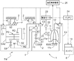
- FIG. 1 is a diagram illustrating an overall configuration of a vehicle on which a vehicle drive device according to a first embodiment is mounted. It is a schematic diagram which shows the structure of the vehicle drive device which concerns on 1st embodiment. It is an operation
- surface which shows the operation state of the some engagement element in each gear stage which concerns on 1st embodiment. It is a speed diagram of the transmission according to the first embodiment. It is a block diagram which shows the structure of the control unit which concerns on 1st embodiment. It is a figure which shows an example of the shift map which concerns on 1st embodiment. It is a flowchart which shows the whole process sequence of the switching control process which concerns on 1st embodiment.
- FIG. 1 is a diagram showing an overall configuration of a vehicle 5 equipped with a vehicle drive device 1 according to the present embodiment.
- the vehicle drive device 1 according to the present embodiment is disposed adjacent to the engine E placed horizontally on the vehicle 5 in the width direction of the vehicle 5.
- the output gear O with which the vehicle drive device 1 is equipped is drive-coupled to the front wheel of the vehicle 5 via the counter gear mechanism, the differential apparatus, etc. which are not shown in figure.
- the vehicle 5 is equipped with a rotating electrical machine MG capable of outputting a driving force.
- the output shaft of the rotating electrical machine MG is drivingly connected to the rear wheel of the vehicle 5.
- the vehicle 5 having such a configuration basically travels by a front wheel drive (FF, Front Engine Front Drive) system using the rotational driving force of the engine E, and if necessary, the engine is driven by the rotational driving force of the rotating electrical machine MG.
- FF Front Engine Front Drive
- the vehicle driving system is capable of traveling in a four-wheel drive (4WD, 4-wheel drive) system.
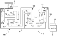
- FIG. 2 is a schematic diagram showing a configuration of a drive transmission system and a hydraulic control system of the vehicle drive device 1 according to the present embodiment.
- a part of the axially symmetric configuration is omitted.
- the solid line indicates the driving force transmission path
- the broken line indicates the hydraulic oil supply path
- the alternate long and short dash line indicates the power supply path.
- the vehicle drive device 1 is drivingly connected to an engine E as a drive force source for driving the vehicle, and the rotational drive force of the engine E input from the input shaft I via the torque converter 11 is obtained.
- the speed is changed by the transmission device TM and transmitted to the output gear O.
- the input shaft I corresponds to the “input member” in the present invention
- the output gear O corresponds to the “output member” in the present invention.
- Engine E is an internal combustion engine that is driven by the combustion of fuel.
- various known engines such as a gasoline engine and a diesel engine can be used.
- an engine output shaft Eo such as a crankshaft of the engine E is drivingly connected to the input shaft I via the torque converter 11.
- the torque converter 11 is a device that transmits the rotational driving force of the engine output shaft Eo of the engine E as a driving force source to the transmission device TM via the input shaft I.
- the torque converter 11 is provided between a pump impeller 11a as an input side rotating member drivingly connected to the engine output shaft Eo, and a turbine runner 11b as an output side rotating member drivingly connected to the input shaft I.
- a stator 11c having a one-way clutch.
- the torque converter 11 transmits the driving force between the driving-side pump impeller 11a and the driven-side turbine runner 11b via hydraulic oil filled therein. Thereby, the rotational driving force of the engine E is transmitted to the input shaft I.
- An engine output shaft Eo of the engine E is preferably connected to the input shaft I in a driving manner, or is connected to the input shaft I through another member such as a damper or a clutch.
- a starter 13 is provided adjacent to the engine E.
- the starter 13 is composed of a direct current motor or the like and is electrically connected to the battery 24.
- the starter 13 is configured to be driven by electric power supplied from the battery 24 in a state where the engine E is stopped, to rotate the engine output shaft Eo, and to start the engine E.
- the torque converter 11 includes a lockup clutch 12 as a friction engagement element for lockup.
- the lock-up clutch 12 is a clutch that connects the pump impeller 11a and the turbine runner 11b so as to rotate integrally to eliminate a rotational difference (slip) between the pump impeller 11a and the turbine runner 11b and increase transmission efficiency. It is. Therefore, the torque converter 11 transmits the driving force of the engine E directly to the input shaft I without passing through the hydraulic oil when the lockup clutch 12 is engaged.
- the torque converter 11 including the lock-up clutch 12 is supplied with hydraulic oil regulated by the hydraulic control device 25.
- a transmission device TM is drivably coupled to an input shaft I that is drivably coupled to a turbine runner 11b as an output side rotating member of the torque converter 11.
- the transmission TM is a device that has a plurality of engagement elements and transmits the rotational driving force of the engine E transmitted from the input shaft I to the output gear O after changing the speed at the gear ratio of each gear.
- the transmission TM is a stepped automatic transmission (stepped transmission) having a plurality of shift stages.
- the transmission TM advances six shift stages (first stage, second stage, third stage, fourth stage, fifth stage, and sixth stage) having different speed ratios (reduction ratios). It is provided as a stage.
- the transmission apparatus TM includes a gear mechanism including a first planetary gear apparatus P1 and a second planetary gear apparatus P2, and a plurality of engagement elements.
- a gear mechanism including a first planetary gear apparatus P1 and a second planetary gear apparatus P2, and a plurality of engagement elements.
- the rotation state of each rotation element of the first planetary gear device P1 and the second planetary gear device P2 is switched, and any two of the plurality of engagement elements are switched.
- the transmission apparatus TM includes a reverse gear in addition to the above six gears.
- the first planetary gear device P1 is a single-pinion type planetary gear mechanism arranged coaxially with the input shaft I. That is, the first planetary gear device P1 is configured to include three rotating elements, that is, a carrier CA1 that supports a plurality of pinion gears, and a sun gear S1 and a ring gear R1 that respectively mesh with the pinion gears.
- the second planetary gear unit P2 is a Ravigneaux type planetary gear mechanism arranged coaxially with the input shaft I.
- the second planetary gear unit P2 includes the first sun gear S2 and the second sun gear S3, the ring gear R2, the long pinion gear that meshes with both the first sun gear S2 and the ring gear R2, and the long pinion gear and the second sun gear. It has four rotating elements, a common carrier CA2 that supports a short pinion gear that meshes with S3.
- the sun gear S1 of the first planetary gear device P1 is fixed to the case 2 as a non-rotating member.
- the carrier CA1 is drivingly connected so as to selectively rotate integrally with the second sun gear S3 of the second planetary gear device P2 via the first intermediate shaft M1, and the second planetary gear via the second intermediate shaft M2. It is drive-coupled so as to selectively rotate integrally with the first sun gear S2 of the device P2.
- the ring gear R1 is drivingly connected so as to rotate integrally with the input shaft I.
- the sun gear S1, the carrier CA1, and the ring gear R1 are the “first rotating element”, “second rotating element”, and “third rotating element” in the present invention, respectively. Is equivalent to.
- These three rotating elements are a sun gear S1 (first rotating element), a carrier CA1 (second rotating element), and a ring gear R1 (third rotating element) in the order of rotation speed.
- the first sun gear S2 of the second planetary gear device P2 is drivingly connected to the carrier CA1 of the first planetary gear device P1 through the second intermediate shaft M2 so as to selectively rotate integrally.
- the carrier CA2 is drivingly connected so as to selectively rotate integrally with the input shaft I, and is selectively fixed to the case 2 as a non-rotating member.
- the ring gear R2 is drivingly connected so as to rotate integrally with the output gear O.
- the second sun gear S3 is drivingly connected to the carrier CA1 of the first planetary gear device P1 through the first intermediate shaft M1 so as to selectively rotate integrally.
- the first sun gear S2, the carrier CA2, the ring gear R2, and the second sun gear S3 are respectively referred to as “first rotating element” and “second rotating element” in the present invention. , “Third rotation element”, and “fourth rotation element”. These four rotating elements are, in order of rotational speed, the first sun gear S2 (first rotating element), the carrier CA2 (second rotating element), the ring gear R2 (third rotating element), and the second sun gear S3 (fourth rotating element). Rotating element).
- the carrier CA1 of the first planetary gear set P1 is selectively connected to the first intermediate shaft M1 by the first clutch C1 and is selectively connected to the second intermediate shaft M2 by the third clutch C3.
- the carrier CA1 of the first planetary gear device P1 is selectively driven and connected to the second sun gear S3 of the second planetary gear device P2 via the first clutch C1 and the first intermediate shaft M1. It is selectively drive-coupled to the first sun gear S2 of the second planetary gear set P2 via the clutch C3 and the second intermediate shaft M2.
- the second intermediate shaft M2 is selectively fixed to the case 2 by the first brake B1.
- the first sun gear S2 of the second planetary gear device P2 is selectively connected to the carrier CA1 of the first planetary gear device P1 via the second intermediate shaft M2 and the third clutch C3. It is selectively fixed to the case 2 by the brake B1.
- the carrier CA2 of the second planetary gear unit P2 is selectively fixed to the case 2 by the one-way clutch F and is selectively driven and connected to the input shaft I by the second clutch C2.
- the one-way clutch F selectively fixes the carrier CA2 to the case 2 by preventing rotation in only one direction.
- the carrier CA2 of the second planetary gear device P2 can be selectively fixed to the case 2 also by the second brake B2.
- the first clutch C1, the second clutch C2, the third clutch C3, the first brake B1, and the second brake B2 are all friction engagement elements. Specifically, these are constituted by a multi-plate clutch or a multi-plate brake operated by hydraulic pressure.
- the friction engagement elements C1, C2, C3, B1, and B2 are controlled to be engaged and released by the hydraulic pressure supplied from the hydraulic control device 25, respectively.
- the one-way clutch F includes an inner race and an outer race, and the inner race is allowed to rotate positively relative to the outer race, but the inner race does not rotate negatively relative to the outer race. It is configured to be blocked.
- the inner race is drivingly connected so as to rotate integrally with the carrier CA2 of the second planetary gear device P2, and the outer race is fixed to the case 2.
- the one-way clutch F functions as a one-way engagement element that is engaged and prevented from rotating when the carrier CA2 of the second planetary gear unit P2 is negatively rotated, and selectively selects the carrier CA2 as the case 2. Fix and stop.
- the first clutch C1, the second clutch C2, the third clutch C3, the first brake B1, the second brake B2, and the one-way clutch F constitute “a plurality of engagement elements” in the present invention. Is done.
- the hydraulic control system draws hydraulic oil stored in an oil pan (not shown) and supplies hydraulic oil to each part of the vehicle drive device 1 as shown in FIG.
- Two types of electric pumps 22 are provided.
- the mechanical pump 21 is an oil pump that is driven by the rotational driving force of the engine E as a driving force source and discharges hydraulic oil.
- a gear pump, a vane pump, etc. are used suitably, for example.
- the mechanical pump 21 is disposed on the opposite side of the engine E with respect to the torque converter 11 in the axial direction of the input shaft I.
- the mechanical pump 21 is drivingly connected to the engine output shaft Eo via the pump impeller 11a of the torque converter 11 and is driven by the rotational driving force of the engine E.
- the mechanical pump 21 basically has a discharge capacity that sufficiently exceeds the amount of hydraulic oil required for the vehicle drive device 1. However, the mechanical pump 21 does not discharge hydraulic oil while the engine output shaft Eo is stopped (that is, when the engine E is stopped). Therefore, the vehicle drive device 1 includes an electric pump 22 as a pump for assisting the mechanical pump 21.
- the electric pump 22 is an oil pump that is driven by the rotational driving force of the electric motor 23 and discharges hydraulic oil irrespective of the rotational driving force of the engine E as a driving force source.
- a gear pump or a vane pump is preferably used as the electric pump 22.
- the electric motor 23 that drives the electric pump 22 is electrically connected to the battery 24 and receives a supply of electric power from the battery 24 to generate a driving force.
- the electric pump 22 is a pump for assisting the mechanical pump 21 and operates in a state where a necessary amount of oil is not supplied from the mechanical pump 21 while the engine E is stopped.
- the hydraulic control system includes a hydraulic control device 25 for adjusting the hydraulic pressure of the hydraulic oil supplied from the mechanical pump 21 and the electric pump 22 to a predetermined pressure.
- the hydraulic control device 25 drains from the regulating valve by adjusting the opening of one or more regulating valves based on the signal pressure from the linear solenoid valve for hydraulic regulation.
- the hydraulic oil pressure is adjusted to one or more predetermined pressures by adjusting the amount of hydraulic oil.
- the hydraulic oil adjusted to a predetermined pressure is supplied to the lock-up clutch 12, the torque converter 11, and the plurality of engagement elements C1, C2, C3, B1, and B2 of the transmission TM at a required level of hydraulic pressure. Is done.
- hydraulic oil is each bearing (not shown) which supports each gear of 1st planetary gear apparatus P1 and 2nd planetary gear apparatus P2, and input shaft I, 1st intermediate shaft M1, and 2nd intermediate shaft M2 rotatably. These parts are also supplied for lubrication and cooling.
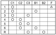
- FIG. 3 is an operation table showing the operation states of the plurality of engagement elements at each gear position.
- “ ⁇ ” indicates that each engaging element is in an engaged state
- “No mark” indicates that each engaging element is in a released (disengaged) state.
- “ ⁇ ” indicates a released state when rotating in one direction (the carrier CA2 rotates in the positive direction), and an engaged state when rotating in the other direction (the carrier CA2 rotates in the negative direction). It shows that it becomes.
- FIG. 4 is a speed diagram of the transmission TM.
- the vertical axis corresponds to the rotational speed of each rotating element. That is, “0” described corresponding to the vertical axis indicates that the rotation speed is zero, the upper side is positive rotation (rotation speed is positive), and the lower side is negative rotation (rotation speed is negative). is there.
- Each of the plurality of vertical lines arranged in parallel corresponds to each rotation element of the first planetary gear device P1 and each rotation element of the second planetary gear device P2. That is, “S1”, “CA1”, and “R1” described on the upper side of each vertical line correspond to the sun gear S1, the carrier CA1, and the ring gear R1 of the first planetary gear device P1, respectively.
- each vertical line are the first sun gear S2, the carrier CA2, the ring gear R2, and the second sun gear of the second planetary gear unit P2, respectively. This corresponds to S3.
- “ ⁇ ” indicates a state in which the rotating element is coupled to the input shaft I that is drivingly coupled to the engine E.
- X indicates a state in which each rotating element is fixed to the case 2 by the first brake B 1, the second brake B 2, or the one-way clutch F.
- “ ⁇ ” indicates a state in which the rotating element is connected to an output gear O that is drivingly connected to a wheel. Note that “1st”, “2nd”, “3rd”, “4th”, “5th”, “6th”, and “Rev” described adjacent to each “ ⁇ ” are realized in the transmission apparatus TM, respectively. Corresponding to the first, second, third, fourth, fifth, sixth and reverse stages.
- the first stage is realized by the engagement of the first clutch C1 and the one-way clutch F in cooperation. That is, in the state where the first clutch C1 is engaged, the rotational driving force of the input shaft I (engine E) input to the ring gear R1 of the first planetary gear device P1 is decelerated based on the gear ratio ⁇ 1, and the second planetary gear device P1 is engaged. It is transmitted to the second sun gear S3 of the gear device P2.
- the first clutch C1 corresponds to the “first engagement element” in the present invention.
- the clutch F is engaged and fixed to the case 2, and the rotational driving force of the second sun gear S3 is decelerated based on the gear ratio ⁇ 3 and transmitted to the output gear O.
- the one-way clutch F corresponds to the “one-way clutch” in the present invention.
- the first stage thus realized, the rotational driving force from the input shaft I (engine E) to the output gear O is transmitted, and the rotational driving force from the output gear O to the input shaft I (engine E) is transmitted.
- the first stage corresponds to the “one-way transmission stage” in the present invention.
- the second stage is realized by cooperation between the engagement of the first clutch C1 and the engagement of the first brake B1. That is, with the first clutch C1 engaged, the rotational driving force of the input shaft I (engine E) is decelerated based on the gear ratio ⁇ 1 and transmitted to the second sun gear S3 of the second planetary gear unit P2. Further, the first sun gear S2 of the second planetary gear device P2 is fixed to the case 2 with the first brake B1 engaged. Then, the rotational driving force of the second sun gear S3 is further decelerated based on the gear ratios ⁇ 2 and ⁇ 3 and transmitted to the output gear O.
- the third stage is realized by cooperation of the engagement of the first clutch C1 and the engagement of the third clutch C3. That is, with the first clutch C1 engaged, the rotational driving force of the input shaft I (engine E) is decelerated based on the gear ratio ⁇ 1 and transmitted to the second sun gear S3 of the second planetary gear unit P2. Further, with the third clutch C3 engaged, the rotational driving force of the input shaft I (engine E) is decelerated based on the gear ratio ⁇ 1 and transmitted to the first sun gear S2 of the second planetary gear unit P2. Then, when the first sun gear S2 and the second sun gear S3 rotate at the same speed, the rotational driving force of the input shaft I (engine E) decelerated based on the gear ratio ⁇ 1 is transmitted to the output gear O as it is. .
- the fourth stage is realized by the cooperation of the first clutch C1 and the engagement of the second clutch C2. That is, with the first clutch C1 engaged, the rotational driving force of the input shaft I (engine E) is decelerated based on the gear ratio ⁇ 1 and transmitted to the second sun gear S3 of the second planetary gear unit P2. Further, with the second clutch C2 engaged, the rotational driving force of the input shaft I (engine E) is transmitted as it is to the carrier CA2 of the second planetary gear device P2. Then, the rotational driving force of the input shaft I (engine E) determined based on the rotational speed of the carrier CA2 and the second sun gear S3 and the gear ratio ⁇ 3 is transmitted to the output gear O.
- the fifth stage is realized by the cooperation of the second clutch C2 and the engagement of the third clutch C3. That is, with the second clutch C2 engaged, the rotational driving force of the input shaft I (engine E) is transmitted as it is to the carrier CA2 of the second planetary gear device P2. Further, with the third clutch C3 engaged, the rotational driving force of the input shaft I (engine E) is decelerated based on the gear ratio ⁇ 1 and transmitted to the first sun gear S2 of the second planetary gear unit P2. Then, the rotational driving force of the input shaft I (engine E) determined based on the rotational speed of the first sun gear S2 and the carrier CA2 and the gear ratio ⁇ 2 is transmitted to the output gear O.
- the sixth stage is realized by cooperation of the engagement of the second clutch C2 and the engagement of the first brake B1. That is, with the second clutch C2 engaged, the rotational driving force of the input shaft I (engine E) is transmitted as it is to the carrier CA2 of the second planetary gear device P2. Further, the first sun gear S2 of the second planetary gear device P2 is fixed to the case 2 with the first brake B1 engaged. Then, the rotational driving force of the carrier CA2 is increased based on the gear ratio ⁇ 2 and transmitted to the output gear O.
- the reverse speed is realized by cooperation of the engagement of the third clutch C3 and the engagement of the second brake B2. That is, with the third clutch C3 engaged, the rotational driving force of the input shaft I (engine E) is decelerated based on the gear ratio ⁇ 1 and transmitted to the first sun gear S2 of the second planetary gear unit P2. Further, the carrier CA2 of the second planetary gear device P2 is fixed to the case 2 with the second brake B2 engaged. Then, the rotational driving force of the first sun gear S2 is decelerated based on the gear ratio ⁇ 2, and the rotational direction is reversed and transmitted to the output gear O.
- the speed change device TM includes at least the first speed, the second speed, the third speed, and the speed changes realized by the engagement of the first clutch C1 as the first engagement element. And a fourth stage. Further, the transmission apparatus TM has fourth, fifth, and sixth stages as shift stages that are realized by engagement of the second clutch C2, which is at least one of the engagement elements different from the first clutch C1. It has.
- the second clutch C2 corresponds to the “second engagement element” in the present invention.
- the first speed, the second speed, the third speed, the fourth speed, and the fifth speed are set in descending order of the speed ratio (reduction ratio) between the input shaft I (engine E) and the output gear O. It has a stage and a sixth stage. Therefore, the first gear as the one-way transmission gear is the gear having the largest gear ratio (reduction ratio) among the forward gears.
- control unit 31 included in the vehicle drive device 1 functions as a core member that controls the operation of each part of the vehicle drive device 1.
- the control unit 31 includes an arithmetic processing unit such as a CPU as a core member, and is configured to be able to read and write data from the arithmetic processing unit, or a data from the arithmetic processing unit. Is configured to have a storage device such as a ROM (Read Only Memory) configured to be able to read (not shown).
- ROM Read Only Memory
- the functional units 32 to 37 of the control unit 31 are configured by software (program) stored in a ROM or the like, hardware such as a separately provided arithmetic circuit, or both. Each of these functional units 32 to 37 is configured to be able to exchange information with each other.
- the memory 41 includes a recording medium capable of storing and rewriting information as a hardware configuration, such as a flash memory, and is configured to exchange information with the control unit 31. ing. Note that the memory 41 may be provided in a storage device included in the control unit 31.
- the vehicle drive device 1 includes a plurality of sensors provided in each part of the vehicle 5, specifically, an input shaft rotation speed sensor Se1, a vehicle speed sensor Se2, and an accelerator opening degree detection sensor Se3.
- the input shaft rotational speed sensor Se1 is a sensor that detects the rotational speed of the input shaft I.
- the vehicle speed sensor Se2 is a sensor that detects the rotational speed of the wheels 6, that is, the vehicle speed.
- the accelerator opening detection sensor Se3 is a sensor that detects an accelerator opening by detecting an operation amount of an accelerator pedal (not shown). Information indicating detection results by these sensors Se1 to Se3 is output to the control unit 31.
- the control unit 31 includes an engine control unit 32, a rotating electrical machine control unit 33, a target gear position determination unit 34, a switching control unit 35, a target rotation speed determination unit 36, and an electric motor drive control unit 37.
- a shift map 42 and an allowable shift table 43 are stored in the memory 41 referred to by the functional units 32 to 37 of the control unit 31.
- the functional units 32 to 37 of the control unit 31 will be described in detail.
- the control unit 31 corresponds to the “vehicle control device” in the present invention. Further, the functional units 32 to 37 included in the control unit 31 cooperate to constitute the “control means” in the present invention.
- the engine control unit 32 is a functional unit that controls the operation of the engine E.
- the engine control unit 32 performs a process of determining an engine operating point and controlling the engine E to operate at the engine operating point.
- the engine operating point is a control command value representing a control target point of the engine E, and is determined by the rotational speed and torque. More specifically, the engine operating point is a command value representing a control target point of the engine E determined in consideration of the vehicle required output (determined based on the vehicle required torque and the engine speed) and the optimum fuel consumption. It is determined by the rotational speed command value and the torque command value. Then, the engine control unit 32 controls the engine E so as to operate at a torque and a rotational speed indicated by the engine operating point.
- the engine control unit 32 is configured to perform idle stop control for stopping the engine E by shutting off the fuel supply to the engine E when a predetermined idle stop condition is satisfied.
- the engine 5 is maintained in a stopped state while the main power supply of the vehicle 5 is able to run while being turned on. That is, the engine E is maintained in a stopped state while the vehicle 5 is traveling, or the engine E is maintained in a stopped state while the vehicle 5 is stopped.
- the idle stop condition is determined in advance in this example based on the rotational speed of the engine E, the accelerator opening, the vehicle speed, and the like.
- the vehicle 5 is stopped (the vehicle speed is zero), or the output of the engine E is decreased when the vehicle 5 is in the coast state (the rotational speed of the engine E when the accelerator opening is equal to or less than a predetermined value).
- the engine control unit 32 also performs control to restart the engine E by restarting the fuel supply to the engine E when the idle stop condition is no longer satisfied. Such control is also included in the above-described idle stop control.
- the rotating electrical machine control unit 33 is a functional unit that controls the operation of the rotating electrical machine MG.
- the rotating electrical machine control unit 33 performs a process of determining a rotating electrical machine operating point and controlling the rotating electrical machine MG to operate at the rotating electrical machine operating point.
- the rotating electrical machine operating point is a control command value representing a control target point of the rotating electrical machine MG, and is determined by the rotational speed and torque. More specifically, the rotating electrical machine operating point is a command value representing a control target point of the rotating electrical machine MG determined in consideration of the vehicle required output and the engine operating point, and is based on the rotational speed command value and the torque command value. Determined.
- the rotating electrical machine control unit 33 controls the rotating electrical machine MG to operate at the torque and the rotational speed indicated by the rotating electrical machine operating point.
- the rotating electrical machine control unit 33 also performs control to switch between a state in which the rotating electrical machine MG generates a driving force with the electric power supplied from the battery 24 and a state in which the rotating electrical machine MG generates power with the rotational driving force of the engine E. Further, the rotating electrical machine control unit 33 also performs regenerative control while the vehicle 5 is traveling.
- the target gear stage determination unit 34 is a functional unit that determines a target gear stage in the transmission apparatus TM based on the accelerator opening and the vehicle speed of the vehicle 5. In order to determine such a target shift speed, the target shift speed determination unit 34 refers to the shift map 42 stored in the memory 41.
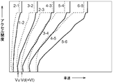
- FIG. 6 is a diagram illustrating an example of the shift map 42 according to the present embodiment.
- the shift map 42 is a map in which a shift stage shift schedule in the transmission apparatus TM is set based on the accelerator opening and the vehicle speed. As shown in this figure, the shift map 42 is set with a plurality of upshift lines and a plurality of downshift lines that are represented by a straight line that rises substantially to the right (the accelerator opening increases as the vehicle speed increases). Has been.
- the upshift line is a line that defines a transition schedule from a gear stage having a large gear ratio (reduction ratio) to a gear stage having a small gear ratio (reduction ratio).
- the downshift line is a line that defines a transition schedule from a gear position having a small gear ratio (reduction ratio) to a gear stage having a large gear ratio (reduction ratio).
- the target shift speed determination unit 34 determines the target shift speed based on the vehicle speed information acquired by the vehicle speed sensor Se2, the accelerator opening information acquired by the accelerator opening detection sensor Se3, and the shift map 42. . Information on the determined target shift speed is output to the switching control unit 35.
- the switching control unit 35 controls the operation of each engagement element C1, C2, C3, B1, B2 based on the target shift stage determined by the target shift stage determination unit 34, thereby changing the shift stage of the transmission apparatus TM. It is a functional unit that performs switching control. That is, as the normal switching control, the switching control unit 35 supplies hydraulic oil to the two engaging elements corresponding to the determined target shift speed via the hydraulic control device 25 to bring the engaging elements into the engaged state. Then, control for realizing the target shift speed is performed. Note that when the vehicle speed and the accelerator opening change and the upshift line or the downshift line is crossed on the shift map 42 in FIG. 6, the target shift stage determination unit 34 is based on the changed accelerator opening and vehicle speed of the vehicle.
- a new target gear position in the transmission apparatus TM is determined. Then, the switching control unit 35 supplies hydraulic oil to the two engagement elements corresponding to the newly determined target shift speed to bring the engagement elements into an engaged state, thereby realizing a new target shift speed.
- the switching control unit 35 is configured to perform each control of engine stop time control, engine restart time control, and shift transition control under predetermined conditions in addition to the above-described normal switching control. ing.
- the engine stop control is a control process executed when the engine control unit 32 stops the engine E by idle stop control.
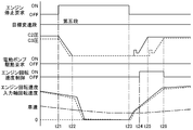
- the switching control unit 35 is in an idle stop state (a state in which the vehicle 5 is stopped or running and the engine E is stopped) under a predetermined condition, and the transmission TM Is controlled to realize the first stage. That is, the switching control unit 35 controls the hydraulic clutch 25 to supply the hydraulic oil to the first clutch C1 through the hydraulic control device 25 so that the first clutch C1 is engaged.
- the switching control unit 35 stops the supply of hydraulic oil to the engagement elements other than the first clutch C1 and puts the engagement elements other than the first clutch C1 into a released state. Thereby, the engagement of the first clutch C1 and the one-way clutch F cooperate to realize the first stage.
- both the following first condition and second condition are satisfied as conditions for controlling the transmission apparatus TM to realize the first stage when the switching control unit 35 is in the idling stop state.
- a first condition it is set that the gear position in the transmission apparatus TM when the engine E is idled is at least a gear position realized by engagement of the first clutch C1.
- the first condition is satisfied when the gear stage when the engine E is idling stopped is one of the first to fourth stages.
- the second condition it is set that the vehicle speed acquired by the vehicle speed sensor Se2 when the engine E is idled is equal to or less than a predetermined release threshold value Vt. In this example, as shown in FIG.
- the predetermined release threshold value Vt is set to a value equal to the vehicle speed Vd that is downshifted from the fourth stage to the third stage with the accelerator opening being zero.
- the electric motor drive control unit 37 consumes the electric power of the battery 24 and drives the electric motor 23 to drive the electric pump 22 and discharge hydraulic oil having a predetermined hydraulic pressure.
- the hydraulic oil of a predetermined hydraulic pressure discharged by driving the electric pump 22 is supplied to the first clutch C1 of the transmission TM via the hydraulic control device 25, and the first clutch C1 is brought into an engaged state.
- the first stage transmits the rotational driving force from the input shaft I (engine E) to the output gear O, and the rotational driving force from the output gear O to the input shaft I (engine E).
- the rotating electrical machine MG can be made to perform regenerative braking using the rotational driving force transmitted from the wheels 6 in a state where energy loss due to dragging of the engine E is suppressed.
- the regeneration efficiency by the electric machine MG can be improved.
- the one-way transmission stage transmits the rotational driving force from the input shaft I to the output gear O, when the engine E is restarted from the idling stop state and the vehicle 5 is driven, the engine E quickly rotates.
- the driving force can be transmitted to the output gear O (wheel 6) via the input shaft I. Therefore, according to the vehicle drive system including the vehicle control device according to the present embodiment, the responsiveness of the driving force transmission when the engine is restarted is improved while improving the regeneration efficiency of the rotating electrical machine MG during idling stop. Can be made.
- the engine E is idled and stopped because the vehicle 5 is decelerating or waiting for a signal.
- the vehicle 5 is driven by restarting the engine E, it is necessary to drive the vehicle 5 from a low (especially zero) state, and thus a large driving force is often required.
- the first speed which is the speed stage with the largest speed ratio (reduction ratio)
- the vehicle 5 is driven from a state where the vehicle speed is low (particularly zero).
- the rotational driving force of the input shaft I (engine E) can be decelerated and a large driving force can be transmitted to the output gear O (wheel 6) with high responsiveness.
- a one-way clutch may be used to realize the gear.
- the one-way clutch provided for such a purpose and the one-way clutch F for realizing the one-way transmission stage in the present invention can be shared, one-way without adding any special parts.
- a transmission stage can be made feasible.
- the switching control unit 35 controls to release all the engaging elements of the transmission apparatus TM in the idle stop state. That is, when the gear stage in the transmission apparatus TM when the engine E is idling stopped is at least a gear stage other than the gear stage realized by the engagement of the first engagement element, or the engine E is idling stopped. When the vehicle speed acquired by the vehicle speed sensor Se2 is greater than the predetermined release threshold Vt, the switching control unit 35 releases all the engagement elements including the first clutch C1 of the transmission TM. Control to achieve a neutral stage.
- the switching control unit 35 performs control so that the transmission apparatus TM realizes the neutral stage when the gear stage when the engine E is idling stopped is any of the fourth to sixth stages. To do. As described above, when one or both of the first condition and the second condition are not satisfied, the neutral stage is realized in the transmission apparatus TM, thereby setting the transmission stage of the transmission apparatus TM when the engine E is restarted. The degree of freedom can be increased, and appropriate response according to the situation can be made possible.
- the electric motor drive control unit 37 controls the electric pump 22 to be in a non-driven state. That is, in such a case, the electric motor drive control unit 37 cuts off the supply of the electric power of the battery 24 to the electric motor 23 to stop the electric motor 23 and put the electric pump 22 in a non-driven state. Thereby, the drive time of the electric motor 23 for driving the electric pump 22 can be shortened, and the life of the electric motor 23 can be extended. In addition, the power of the battery 24 for driving the electric motor 23 can be saved.
- the engine restart control is a control process executed when the engine control unit 32 restarts the engine E by idle stop control.
- the switching control unit 35 sequentially engages two engagement elements corresponding to the respective target shift speeds in order to realize the target shift speeds in the transmission apparatus TM. Combine.
- the shift stage in the transmission apparatus TM is either the first stage as the one-way transmission stage as described above, or the neutral stage in which all the engagement elements are released. Is realized.
- the switching control unit 35 performs control so that the engagement elements other than the first clutch C1 corresponding to the target shift speed are engaged.
- the target shift speed is realized.
- the switching control unit 35 Is controlled so as to engage the engagement element other than the second clutch C2 corresponding to the target shift speed after first engaging the second clutch C2 as the second engagement element. Realize the stage.
- the second clutch C2 to be engaged first has a predetermined engagement in which the rotation speed of the input shaft I is set in advance. It is engaged when the starting rotational speed Ng or more is reached.
- the engaging elements other than the first clutch C1 or the second clutch C2 that are to be engaged later are the engine rotational speeds.
- Engaged after control is a control process for controlling the engine E so that the rotation speed of the input shaft I becomes a predetermined target rotation speed.
- the target rotational speed is determined based on the traveling speed of the vehicle 5 and the target shift speed in the transmission apparatus TM when the engine E is restarted. That is, based on the traveling speed of the vehicle 5 and the gear ratio of the target gear, two members (for example, the third clutch C3) that are engaged and connected to each other in an engagement element that is engaged later.
- the target rotational speed of the input shaft I is determined so as to be a value very close to zero.
- such a target rotational speed is determined by the target rotational speed determination unit 36 performing a calculation based on the vehicle speed acquired by the vehicle speed sensor Se2 and the gear ratio of the target shift stage.
- the engine control unit 32 outputs a rotational speed command value corresponding to the determined target rotational speed, whereby the engine E is controlled so that the rotational speed of the input shaft I becomes the target rotational speed, and then the first clutch Engagement elements other than C1 or the second clutch C2 are engaged.
- the target gear stage is realized by controlling the two engaging elements to synchronize with each other (after the rotating speeds are substantially equal) after the engine rotating speed control is engaged. It is possible to suppress the occurrence of a shift shock during running.
- the switching control is performed when the target shift stage when the engine E is restarted is any of the fourth to sixth stages.
- the part 35 engages the third clutch C3 with the first clutch C1 already engaged, and first realizes the third stage. Thereafter, the target shift speed is realized through the third speed by controlling the two engagement elements corresponding to the target shift speed to be in the engaged state.
- the switching control unit 35 engages the first clutch C1 after engaging the second clutch C2, and first realizes the fourth stage. After that, by controlling the engagement elements other than the first clutch C1 among the two engagement elements corresponding to the target shift speed, the target shift speed is realized through the fourth speed. .
- the switching control unit 35 basically controls the engine speed. After performing the speed control, the engagement elements to be engaged later are engaged to realize the target shift speed before the change, and then the new target shift speed after the change is realized. The engagement state of the combination element is switched. However, this is a case where the target shift speed is changed to a new shift speed after the first clutch C1 or the second clutch C2 is engaged first, and the target shift speed change pattern corresponds to a predetermined allowable shift pattern. In this case, in order to realize the new target shift speed after the change at an early stage, the shift transition control described below is exceptionally performed.
- the engine control unit 32 stops outputting the rotation speed command value corresponding to the target rotation speed, so that the engine rotation speed control is stopped, and the switching control unit 35 is configured to change the target shift speed after the change.
- the engagement element corresponding to the changed target shift speed in the transmission apparatus TM is engaged to realize the shift speed.
- the permissible shift pattern is a change between gears having common engagement elements that are engaged first and different engagement elements that are engaged later, and from a gear having a small reduction ratio.
- the change pattern corresponds to a change to a gear stage with a large reduction ratio (downshift).
- the engagement element to be engaged first is the first clutch C1 as the first engagement element or the second clutch C2 as the second engagement element.
- the first speed stage, the second speed stage, and the third speed stage are provided as shift speeds realized by the engagement of the first clutch C1.
- the fourth speed, the fifth speed, and the sixth speed are provided as the shift speeds realized by the engagement of the second clutch C2. Therefore, in this example, a change pattern is permitted in which a downshift from the first stage to the third stage and a downshift from the fourth stage to the sixth stage are allowed. 2nd to 1st, 3rd to 2nd, 3rd to 1st, 5th to 4th, 6th to 5th, 6th to 4th Are included in the allowable shift pattern.
- the shift to the target shift stage is performed through the fourth stage as described above.
- the shift to the target shift stage is performed through the fourth stage as described above.
- 6 patterns are further included in the allowable shift pattern. Therefore, in this example, a total of 12 change patterns are set as the allowable shift patterns.
- These allowable shift patterns are stored in the memory 41 as an allowable shift table 43.
- the initial target shift speed when restarting the engine E is realized (specifically, the engagement engaged after and after the engagement of the first clutch C1 or the second clutch C2). If the target shift speed is changed to a new shift speed before the combined element is completely engaged), it is determined whether or not to perform shift transition control with reference to the permissible shift table 43. It is configured to be able to.
- the switching control unit 35 maintains the first clutch C1 or the second clutch C2 previously engaged in the engaged state, and the engagement element to be engaged later corresponds to the target gear stage before the change.
- the changed target shift speed is realized by switching from the engaging element to the engagement element corresponding to the changed target shift speed.
- the engine rotational speed control described above is not executed.
- hydraulic oil is supplied in accordance with a predetermined command signal via the hydraulic control device 25, and a predetermined engagement element corresponding to the changed target gear stage is engaged.
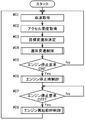
- FIG. 7 is a flowchart showing an overall processing procedure of the switching control processing of the vehicle drive device 1 according to the present embodiment.
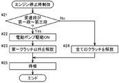
- FIG. 8 is a flowchart showing a processing procedure for engine stop time control according to Step # 06 of FIG.
- FIG. 9 is a flowchart showing a processing procedure for engine restart control according to step # 08 of FIG.
- the procedure of the control process of the vehicle drive device 1 described below is executed by the functional units 32 to 37 of the control unit 31.
- the arithmetic processing device provided in the control unit 31 operates as a computer that executes the program configuring the function units 32 to 37 described above.
- the traveling speed (vehicle speed) of the vehicle 5 is acquired by receiving an output signal from the vehicle speed sensor Se2 (step # 01), and the accelerator The accelerator opening is acquired in response to the output signal from the opening detection sensor Se3 (step # 02).
- the target shift speed determination unit 34 determines the target shift speed based on the acquired information on the vehicle speed and accelerator opening and the shift map 42 stored in the memory 41 (step # 03).
- the switching control unit 35 controls the operation of each engagement element to switch the shift speed of the transmission apparatus TM and performs normal shift control (step # 04).
- step # 05 it is determined whether a predetermined idle stop condition is satisfied and an engine stop request is turned on (step # 05). If it is determined that the engine stop request is not on, that is, it is off (step # 05: No), the process returns to step # 01 again to repeat steps # 01 to # 05.
- step # 06 the engine stop control is executed (step # 06).
- step # 07 it is determined whether the engine stop request is turned off because the idle stop condition is not satisfied and the engine stop request is turned off while the engine E is in the idle stop state due to the engine stop request. If it is determined that the engine stop request is turned off (step # 07: Yes), engine restart control is executed (step # 08). Thereafter, the process returns to step # 01 again, and the processes from step # 01 to step # 08 are sequentially repeated while the vehicle 5 is traveling.
- Step # 06 Processing Procedure for Engine Stop Control
- the engine stop control first, it is determined whether or not both the first condition and the second condition are satisfied. In the present embodiment, specifically, it is determined whether or not the gear position when the engine E is idle-stopped is any one of the first speed to the third speed (step # 21). If it is determined that the engine is in any one of the first stage to the third stage (step # 21: Yes), the mechanical pump 21 may discharge a sufficient amount of hydraulic oil by the engine E being idle stopped. When it becomes impossible, the electric motor drive control part 37 drives the electric pump 22 by driving the electric motor 23 to discharge the hydraulic oil having a predetermined hydraulic pressure (step # 22).
- step # 23 the switching control unit 35 releases engagement elements other than the first clutch C1 (for example, the first brake B1 in the second stage and the third clutch C3 in the third stage) (step #). 23).
- the first clutch C1 is maintained in the engaged state by the hydraulic pressure of the hydraulic oil discharged from the electric pump 22.
- the engagement of the first clutch C1 and the one-way clutch F cooperate to realize a first stage as a one-way transmission stage.
- the processing order of step # 22 and step # 23 may be reversed.
- step # 21: No when it is determined that the current position is not any of the first to third stages, that is, any of the fourth to sixth stages (step # 21: No), the switching control unit 35 is Then, all the engagement elements including the first clutch C1 are released (step # 24). In this state, a neutral stage is realized. In the state where the neutral stage is realized, the electric pump 22 is not driven, unlike the case where it is determined that the neutral stage is one of the first stage to the third stage and the first stage is realized. As described above, when the engine E is in the idling stop, the gear stage of the transmission apparatus TM is maintained in a state in which the first stage or the neutral stage is realized in accordance with the gear stage at the time of idling stop (step # 25). ). The engine stop control is thus completed.
- Step # 08 Processing Procedure for Engine Restart Control
- step # 41 it is determined whether or not the gear position of the transmission apparatus TM in the state where the engine E is idling stopped (step # 41). If it is determined that the engine is in the first stage (step # 41: Yes), when the rotational speed of the engine E increases and the mechanical pump 21 can discharge a sufficient amount of hydraulic fluid, The motor drive control unit 37 stops the electric motor 23 so that the electric pump 22 is not driven (step # 42). Note that the processing order of step # 42 and step # 43 may be reversed depending on the timing at which the mechanical pump 21 can discharge a sufficient amount of hydraulic fluid.
- step # 43 it is determined whether or not the target shift speed when the engine E is restarted from the idle stop state is the first speed (step # 43). If it is determined that the target shift speed is the first speed (step # 43: Yes), the first speed has already been realized, and therefore the engine restart control is terminated. On the other hand, if it is determined that the target shift speed is not the first speed (step # 43: No), the process proceeds to step # 47, which will be described later, in order to engage the engagement elements other than the first clutch C1. .
- step # 41 when it is determined that the gear position of the transmission apparatus TM in the state where the engine E is idling stopped is not the first stage, that is, the neutral stage (step # 41: No), the input shaft rotational speed is determined.
- the rotational speed of the input shaft I is acquired by the sensor Se1 (step # 44). Further, it is determined whether or not the acquired rotation speed of the input shaft I is equal to or higher than a predetermined engagement start rotation speed Ng (step # 45). And when it becomes more than the engagement start rotation speed Ng (step # 45: Yes), the 2nd clutch C2 as a 2nd engagement element is first engaged first (step # 46). Thereafter, in order to engage engagement elements other than the second clutch C2, the process proceeds to step # 47 described below.
- the target rotation speed of the input shaft I is determined by the target rotation speed determination unit 36 (step #). 47). Since the method for determining the target rotational speed of the input shaft I by the target rotational speed determining unit 36 has already been described, detailed description thereof is omitted here. Further, the rotational speed of the input shaft I is acquired by the input shaft rotational speed sensor Se1 (step # 48). Then, it is determined whether or not the acquired rotation speed of the input shaft I is substantially equal to the target rotation speed determined by the target rotation speed determination unit 36, that is, whether or not the rotation is synchronized (step # 49). When it is determined that they are synchronized (step # 49: Yes), the switching control unit 35 engages a predetermined engagement element corresponding to the target gear position (step # 50) and performs engine restart control. finish.
- step # 49: No it is determined whether or not the target shift speed determined by the target shift speed determination unit 34 based on the vehicle speed and the accelerator opening is changed. Determination is made (step # 51). When it is determined that the target gear position has not been changed (step # 51: No), the process returns to step # 49 again, and the processes from step # 49 to step # 51 are repeatedly performed. On the other hand, when it is determined that the target shift speed has been changed (step # 51: Yes), it is determined whether or not the target shift speed change pattern corresponds to a predetermined allowable shift pattern (step # 52). ).
- step # 52 it is determined with reference to the allowable shift table 43 stored in the memory 41 whether the allowable shift pattern is applicable.
- the switching control unit 35 engages a predetermined engagement element corresponding to the target shift speed before the change.
- step # 50 the engine restart control is terminated.
- a predetermined engagement element corresponding to the changed target shift speed is engaged to realize the changed target shift speed.
- step # 51 if it is determined that the target shift speed has been changed (step # 51: Yes), and if it is further determined that the target shift speed change pattern corresponds to the allowable shift pattern (step # 52: Yes), shift transition control is executed (step # 53). Since the processing content of this shift transition control has already been described, detailed description thereof is omitted here. This completes the engine restart control.
- FIG. 10 shows an example in which the gear position when the engine E is idled is the third speed and the target gear position when the engine E is restarted is the first speed.
- FIG. 11 shows an example in which the gear position when the engine E is idled and the target gear position when the engine E is restarted are both the third speed.
- FIG. 12 shows an example in which the shift speed when the engine E is idled and the target shift speed when the engine E is restarted are both the fifth speed.
- FIG. 10 shows an example in which the gear position when the engine E is idled is the third speed and the target gear position when the engine E is restarted is the first speed.
- FIG. 11 shows an example in which the gear position when the engine E is idled and the target gear position when the engine E is restarted are both the third speed.
- FIG. 12 shows an example in which the shift speed when the engine E is idled and the target shift speed when the engine E is restarted are both the fifth speed.
- the gear position when the engine E is idling stopped is the third speed and the target gear position when the engine E is restarted is the first speed.
- the switching control unit 35 keeps the first clutch C1 in the engaged state.
- the hydraulic pressure supplied to the third clutch C3 is controlled to gradually decrease.
- the third clutch C3 is completely released, so that the vehicle 5 is running and the engine E is stopped.
- One stage is realized.
- the electric pump drive request is turned on. Then, the discharge of hydraulic oil by the drive of the electric pump 22 is started. During idle stop, the first clutch C1 is maintained in the engaged state by the hydraulic pressure of the hydraulic oil discharged by the electric pump 22.
- the vehicle 5 is stopped after that, but the first stage as the one-way transmission stage is maintained even when the vehicle is stopped. Then, it is assumed that the target shift speed becomes the first speed while the vehicle is stopped and the engine stop request is turned off at t04 in that state.
- the rotational driving force of the input shaft I engine E
- the state transmitted to the wheel 6 side is realized early. That is, the response of driving force transmission when the engine E is restarted from the idle stop state is greatly improved.
- the electric pump drive request is turned off, and the electric pump 22 is brought into a non-driven state.
- the gear position when the engine E is idled and the target gear position when the engine E is restarted are both the third speed.
- the flow of the switching process up to t13 is the same as the flow of the switching process up to t03 in FIG.
- the vehicle 5 continues to run at a constant vehicle speed or higher even when the engine E is idle stopped, and the target shift speed is maintained at the third speed, which is different from the example of FIG. 10 described above. Yes.
- the engine stop request is turned off at t14 while the target shift speed is maintained at the third speed.
- the first stage as the one-way transmission stage is realized in the transmission TM, and the first clutch C1 is maintained in the engaged state.
- the control unit 35 controls to engage the third clutch C3, a state in which the rotational driving force of the input shaft I (engine E) is transmitted to the wheel 6 side when the engine E is restarted is realized. The That is, since the target shift speed is realized by engaging only the third clutch C3, the responsiveness of the driving force transmission when the engine E is restarted from the idle stop state is improved also in this case. .
- the engine speed control described above is executed from t15 to t17.
- the third clutch C3 is completely engaged and the engine rotational speed control ends.
- the electric pump drive request is turned off, and the electric pump 22 is brought into a non-driven state.
- the engine stop request is turned off at t23 while the target shift speed is maintained at the fifth speed.
- the neutral stage is realized in the transmission TM, and all the engagement elements are in the released state.
- the third clutch C3 is controlled to be sequentially engaged.
- the second clutch C2 is engaged first, and the third clutch C3 is engaged later.
- the second clutch C2 is engaged when the rotational speed of the input shaft I becomes equal to or higher than a predetermined engagement start rotational speed Ng at t25.
- the third clutch C3 is engaged, the engine speed control described above is executed from t24 to t26. When the rotational speed of the input shaft I becomes substantially equal to the target rotational speed at t26, the third clutch C3 is completely engaged and the engine rotational speed control ends.
- the target shift speed is changed from the fifth speed to the fourth speed. Since the change pattern from the fifth stage to the fourth stage corresponds to the above-described allowable shift pattern, the engine speed control is stopped and the above-described shift transition control is executed after t36. That is, from t36 to t37, the third clutch C3 is released while the second clutch C2 is maintained in the engaged state so as to shift to the fourth stage before the fifth stage is realized, and the first clutch Control to engage C1.
- the hydraulic pressure of the hydraulic oil supplied to the third clutch C3 is changed from a constant maintenance pressure to t37 so that a shift shock does not occur when the third clutch C3 and the first clutch C1 are replaced. Is gradually raised to zero and then zeroed. Then, the first clutch C1 and the second clutch C2 are completely engaged at t37, and the third clutch C3 is completely released at t38, thereby realizing the fourth stage that is the changed target shift stage. To do.
- FIG. 14 is a schematic diagram illustrating a configuration of a drive transmission system of the vehicle drive device 1 according to the present embodiment. Note that, in FIG. 14, as in FIG. 2, an axisymmetric configuration is partially omitted. Further, since the configuration of the hydraulic control system is the same as that in the first embodiment, the hydraulic control system is omitted here.
- the configuration of the vehicle drive device 1 is equal to the configuration in which the first brake B1 is removed from the vehicle drive device 1 in the first embodiment. And since this vehicle drive device 1 is not provided with 1st brake B1, the number of the gear stages with which transmission TM is provided is fewer than said 1st embodiment.
- the contents of the control processing executed by the functional units 32 to 37 of the control unit 31 when the engine E is idled are partially different from those of the first embodiment.
- Other configurations are basically the same as those in the first embodiment.
- the vehicle drive device 1 according to the present embodiment and the control unit 31 for controlling the vehicle drive device 1 will be described focusing on differences from the first embodiment.
- FIG. 15 is an operation table showing operation states of a plurality of engagement elements at each gear position according to the present embodiment.
- FIG. 16 is a speed diagram of the transmission apparatus TM.
- the transmission apparatus TM switches the operating states of the plurality of engagement elements to change the forward stage as the first stage, the second stage, the third stage, and the first stage. It has four shift stages.
- the second stage and the sixth stage in the first embodiment are not provided in correspondence with the configuration equivalent to the configuration in which the first brake B1 is removed from the vehicle drive device 1 in the first embodiment.
- the first stage, the second stage, the third stage, and the fourth stage in the present embodiment correspond to the first stage, the third stage, the fourth stage, and the fifth stage in the first embodiment, respectively. It has become.
- the shift map 42 stored in the memory 41 is also different from that shown in FIG. 6 (not shown).
- the transmission TM includes at least a first speed, a second speed, and a third speed as shift speeds realized by engagement of the first clutch C1 as the first engagement element.
- the transmission apparatus TM includes a third stage and a fourth stage as shift stages realized by engagement of at least the second clutch C2 as the second engagement element.
- the first stage is a one-way transmission stage that is realized by cooperation of the engagement of the first clutch C1 and the one-way clutch F.
- first condition it is set that the gear position in the transmission apparatus TM when the engine E is idled is at least a gear position realized by engagement of the first clutch C1.
- first condition is satisfied when the gear stage when the engine E is idling stopped is one of the first to third stages.
- second condition it is set that the vehicle speed acquired by the vehicle speed sensor Se2 when the engine E is idled is equal to or less than a predetermined release threshold value Vt.
- the predetermined release threshold value Vt is set to a value equal to the vehicle speed Vd ′ (not shown) that is downshifted from the third stage to the second stage with the accelerator opening being zero.
- this one-way transmission stage does not transmit the rotational driving force from the output gear O to the input shaft I, and therefore drags the engine E during idling stop (the engine E accompanying the input shaft I). Is avoided.
- the rotating electrical machine MG can be made to perform regenerative braking using the rotational driving force transmitted from the wheels 6 in a state where energy loss due to dragging of the engine E is suppressed. The regeneration efficiency by the electric machine MG can be improved.
- the one-way transmission stage transmits the rotational driving force from the input shaft I to the output gear O, when the engine E is restarted from the idling stop state and the vehicle 5 is driven, the engine E quickly rotates.
- the driving force can be transmitted to the output gear O (wheel 6) via the input shaft I. Therefore, even in the vehicle drive system including the vehicle control device according to the present embodiment, the responsiveness of the driving force transmission when the engine is restarted is improved while improving the regeneration efficiency of the rotating electrical machine MG during idling stop. Can do.
- the switching control unit 35 releases all the engagement elements of the transmission apparatus TM in the idle stop state. Specifically, when the speed change stage when the engine E is idled is the third speed or the fourth speed, the switching control unit 35 includes all the engagement elements including the first clutch C1 of the transmission apparatus TM. Is controlled so as to realize a neutral stage. As described above, when one or both of the first condition and the second condition are not satisfied, the neutral stage is realized in the transmission apparatus TM, thereby setting the transmission stage of the transmission apparatus TM when the engine E is restarted. The degree of freedom can be increased, and appropriate response according to the situation can be made possible.
- the first clutch C1 as the first engagement element or the second clutch C2 as the second engagement element is engaged first.
- the first speed, the second speed, and the third speed are provided as the shift speeds realized by the engagement of the first clutch C1.
- a third speed stage and a fourth speed stage are provided as shift speeds realized by the engagement of the second clutch C2. Therefore, in this example, a change pattern is permitted in which a downshift between the first stage and the second stage and a downshift between the third stage and the fourth stage are allowed. That is, two patterns of the second stage to the first stage and the fourth stage to the third stage are included in the allowable shift pattern.
- the allowable shift pattern when downshifting from the fourth stage to the first stage or the second stage, control is performed so that the third stage is first realized and then the target shift stage is shifted. Therefore, the allowable shift pattern further includes two patterns from the fourth stage to the first stage and from the fourth stage to the second stage. Therefore, in this example, a total of four change patterns are set as the allowable shift patterns.
- the first condition and the second condition are set.
- the switching control unit 35 is in the idle stop state and the transmission device TM is in the one-way shift stage.
- the case where control is performed to realize one stage has been described as an example.
- the embodiment of the present invention is not limited to this. That is, for example, without setting such a condition, the switching control unit 35 is configured to control the transmission apparatus TM to unconditionally realize the first speed as the one-way speed in the idle stop state. Is also one preferred embodiment of the present invention.
- the switching control unit 35 performs control so that the transmission apparatus TM realizes the first stage as the one-way shift stage in the idle stop state.
- the configuration is also one of the preferred embodiments of the present invention.
- the switching control unit 35 is unidirectional when the speed stage in the transmission apparatus TM when the engine E is idlingly stopped is any one of the first speed to the fourth speed. Control is performed so as to realize the first gear as the gear.
- the switching control unit 35 performs the one-way shift when the shift stage in the transmission apparatus TM when the engine E is idled is any one of the first to third stages. Control is performed to realize the first stage as the stage.
- the predetermined release threshold value Vt can be set as appropriate.
- the predetermined release threshold Vt is set to a vehicle speed Vu or higher that is upshifted from the second stage to the third stage when the accelerator opening is zero, and the predetermined opening threshold Vt is zero when the accelerator opening is zero.
- One of the preferred embodiments of the present invention is to set an arbitrary value below the vehicle speed Vd that is downshifted from the fourth stage to the third stage. The same applies to the second embodiment.
- the electric motor drive control unit 37 is electrically operated.
- the case where the pump 22 is controlled to be in the non-driven state has been described as an example.
- the embodiment of the present invention is not limited to this. That is, even when the neutral stage is realized during idling stop of the engine E, the electric motor drive control unit 37 may be configured to control the electric pump 22 to be driven.
- the output of the hydraulic oil discharged by the electric pump 22 is such that the discharge amount is such that the first planetary gear device P1, the second planetary gear device P2, and the bearings can be properly lubricated. It is preferable that the electric pump 22 is driven.
- the case where the first gear, which is the gear having the largest gear ratio (reduction ratio), is set as the one-way transmission gear has been described as an example.
- the embodiment of the present invention is not limited to this. That is, for example, it is also a preferred embodiment of the present invention to set the second speed, which is the speed stage having the second largest speed ratio (reduction ratio), as the one-way transmission speed.
- the one-way clutch F as a one-way clutch is engaged only when the second intermediate shaft M2 rotates negatively, and the second intermediate shaft M2 and the second planetary planet are engaged.
- the first sun gear S2 of the gear device P2 can be selectively fixed to the case 2 and stopped.
- the first stage is realized by the cooperation of the engagement of the first clutch C1 and the engagement of the second brake B2 and the second stage is realized by the cooperation of the engagement of the first clutch C1 and the one-way clutch F. It can be set as the structure implement
- the first clutch C1 or the second clutch to be engaged later out of the two engagement elements that are engaged in the transmission device TM when the engine E is restarted.
- the case where the engaging elements other than the clutch C2 are engaged after performing the engine speed control has been described as an example.
- the embodiment of the present invention is not limited to this. That is, it is also a preferred embodiment of the present invention that the engaging element to be engaged later is engaged without executing such engine rotation speed control.
- hydraulic oil in accordance with a predetermined command signal is supplied to the engagement element to be engaged later through the hydraulic control device 25, and the target shift stage is realized through the preliminary filling phase, the torque phase, and the inertia phase. It can be set as the structure made to do.
- the target shift speed is changed to a new shift speed before the initial target shift speed when the engine E is restarted, and the target shift speed is
- the change pattern corresponds to a predetermined allowable shift pattern
- the switching control unit 35 executes the shift transition control has been described as an example.
- the embodiment of the present invention is not limited to this. That is, it is one of the preferred embodiments of the present invention that such an allowable shift pattern is not set and the shift transition control is not executed.
- the switching control unit 35 engages an engagement element to be engaged later to realize the target shift speed before the change, and after passing through the target shift speed before the change, The engagement state of each engagement element can be switched so as to realize the target shift speed.
- the switching control unit 35 is An example has been described in which the second clutch C2 as the engagement element is first engaged, and then control is performed so that engagement elements other than the second clutch C2 corresponding to the target shift speed are engaged.
- the embodiment of the present invention is not limited to this. That is, it is also possible to control so that the engagement element other than the second clutch C2 corresponding to the target shift stage is engaged first, and then the second clutch C2 as the second engagement element is engaged. This is one of the preferred embodiments of the present invention.
- the first clutch C1 and the second clutch C2 are engaged in this order
- the third clutch C3 and the second clutch C2 may be engaged in this order
- the first brake B1 and the second clutch C2 may be engaged in this order.
- the second intermediate shaft M2 is in an idle state in a state where all the engagement elements are in the released state and the neutral stage is realized. Therefore, if any one of the first clutch C1, the third clutch C3, and the first brake B1 is engaged first, the number of allowable shift patterns is reduced, but the engagement is performed when these are engaged. There is an advantage that the occurrence of shock can be prevented.
- the transmission TM is a single pinion type first planetary gear device P1 configured with three rotating elements, and a Ravigneaux configured with four rotating elements.
- mold 2nd planetary gear apparatus P2 was demonstrated as an example.
- the embodiment of the present invention is not limited to this. That is, the specific configuration inside the transmission apparatus TM can be changed as appropriate.
- the transmission TM may be configured by including only the second planetary gear unit P2, or the transmission TM may be configured by combining a double pinion type planetary gear unit and a Ravigneaux type planetary gear unit P2, or
- One of the preferred embodiments of the present invention is to configure the transmission TM by combining three or more single-pinion type or double-pinion type planetary gear units.
- the vehicle is configured to control a four-wheel drive (4WD, 4-wheel drive) type vehicle drive system configured to be connected to the rear wheels of the vehicle 5.
- the embodiment of the present invention is not limited to this. That is, a vehicle having a configuration in which the output gear O included in the vehicle drive device 1 is drivingly connected to the rear wheel of the vehicle 5 and the output shaft of the rotating electrical machine MG capable of outputting driving force is drivingly connected to the front wheel of the vehicle 5.
- the output shaft of the rotating electrical machine MG may be drivingly connected to the output gear O included in the vehicle drive device 1. Even in these cases, as in the case of each of the above-described embodiments, the responsiveness of the driving force transmission at the time of restarting the engine is improved while improving the regeneration efficiency of the rotating electrical machine MG during idling stop. Can do.
- control unit 31 is configured to control the vehicle 5 that includes only the vehicle drive device 1 and does not include the rotating electrical machine MG.
- the control unit 31 is configured to control the vehicle 5 that includes only the vehicle drive device 1 and does not include the rotating electrical machine MG.
- the present invention is suitably used for a control device for controlling a vehicle drive device for a vehicle having an idle stop function, and a vehicle drive system provided with a vehicle drive device controlled by such a control device. Can do.
Landscapes
- Engineering & Computer Science (AREA)
- Transportation (AREA)
- Mechanical Engineering (AREA)
- Chemical & Material Sciences (AREA)
- Combustion & Propulsion (AREA)
- Automation & Control Theory (AREA)
- Control Of Transmission Device (AREA)
- Control Of Driving Devices And Active Controlling Of Vehicle (AREA)
- Hybrid Electric Vehicles (AREA)
- Output Control And Ontrol Of Special Type Engine (AREA)
- Structure Of Transmissions (AREA)
- Electric Propulsion And Braking For Vehicles (AREA)
Abstract
Description
一方、一方向伝達段は、入力部材から出力部材への回転駆動力は伝達するため、アイドル停止状態からエンジンが再始動して車両を駆動させる際に、速やかにエンジンの回転駆動力を、入力部材を介して出力部材に伝達することができる。
したがって、上記の特徴構成によれば、アイドル停止中のエンジンの引きずりを回避しつつ、エンジンの再始動時における駆動力伝達の応答性を向上させることができる。
すなわち、エンジンが停止される際の変速装置における変速段が、少なくとも第一係合要素が係合されて実現されている場合には、第一係合要素以外の係合要素を解放させるだけで、容易かつ速やかに一方向伝達段を実現させることができる。
また、エンジンが停止される際の変速装置における変速段が、第一係合要素が解放されるとともに他の二つの係合要素が係合されて実現されている場合には、全ての係合要素を解放させることで、エンジンの再始動時における変速装置の変速段の設定の自由度を高め、状況に応じた適切な対応を可能とすることができる。
すなわち、エンジンが停止される際の車両の走行速度が所定の解放閾値以下の比較的低速での走行時には、エンジンの再始動時に車両を駆動するための駆動力が比較的速やかに必要となる場合が多い。よって、そのような条件の下では第一係合要素を係合させて一方向伝達段を実現させておくことで、エンジンの再始動時における駆動力伝達の応答性を向上させることができる。
また、エンジンが停止される際の車両の走行速度が所定の解放閾値より大きい比較的高速での走行時には、エンジンの再始動時に車両を駆動するための駆動力はあまり必要でない場合が多い。よって、そのような条件の下では全ての係合要素を解放させることで、エンジンの再始動時における変速装置の変速段の設定の自由度を高め、状況に応じた適切な対応を可能とすることができる。
また、前進用変速段の中で減速比が最も大きい変速段では、一般にアクセルオフした際にエンジンブレーキが効き過ぎてしまうことが多いことから、そのようなエンジンブレーキによるショックを低減するために当該減速比が最も大きい変速段を実現するのに一方向クラッチを利用する場合がある。上記の構成では、そのような目的で設けられる一方向クラッチと、本発明における一方向伝達段を実現するための一方向クラッチとを共用させることができるので、特別な部品を追加することなく一方向伝達段を実現可能とすることができる。
また、目標変速段が減速比の小さい変速段から減速比の大きい変速段へ変更(ダウンシフト)される場合には、より大きな駆動力が必要とされることから、変更後の目標変速段を早期に実現させることが好ましい。
したがって、上記の構成によれば、許容シフトパターンを適切に設定することができ、必要な場合には目標変速段を早期に実現させることができる。
したがって、上記の特徴構成によれば、アイドル停止中の回転電機の回生効率が良好であるとともに、エンジンの再始動時における駆動力伝達の応答性が良好な車両駆動システムとすることができる。
本発明に係る車両用制御装置の第一の実施形態について、図面を参照して説明する。本実施形態においては、本発明に係る車両用制御装置を、ハイブリッド車両用の駆動装置に適用した場合を例として説明する。図1は、本実施形態に係る車両用駆動装置1を搭載した車両5の全体構成を示す図である。この図に示すように、本実施形態に係る車両用駆動装置1は、車両5に横置きされるエンジンEに対して車両5の幅方向に隣接して配置されている。そして、車両用駆動装置1が備える出力ギヤOが、図示しないカウンタギヤ機構及びディファレンシャル装置等を介して車両5の前輪に駆動連結されている。また、本実施形態においては、車両5には駆動力を出力可能な回転電機MGが搭載されている。回転電機MGの出力軸は、車両5の後輪に駆動連結されている。このような構成を備えた車両5は、基本的にはエンジンEの回転駆動力により前輪駆動(FF、Front Engine Front Drive)方式で走行し、必要に応じて回転電機MGの回転駆動力でエンジンEの回転駆動力をアシストすることにより四輪駆動(4WD、4-wheel drive)方式で走行することが可能な車両駆動システムとなっている。
まず、本実施形態に係る車両用駆動装置1の構成について説明する。図2は、本実施形態に係る車両用駆動装置1の駆動伝達系及び油圧制御系の構成を示す模式図である。なお、この図2は、軸対称の構成を一部省略して示している。この図において、実線は駆動力の伝達経路を示し、破線は作動油の供給経路を示し、一点鎖線は電力の供給経路を示している。この図に示すように、車両用駆動装置1は、車両駆動用の駆動力源としてのエンジンEに駆動連結され、トルクコンバータ11を介して入力軸Iから入力されるエンジンEの回転駆動力を、変速装置TMで変速して出力ギヤOに伝達する構成となっている。本実施形態においては、入力軸Iが本発明における「入力部材」に相当し、出力ギヤOが本発明における「出力部材」に相当する。
次に、上述した車両用駆動装置1の油圧制御系について説明する。油圧制御系は、図示しないオイルパンに蓄えられた作動油を吸引し、車両用駆動装置1の各部に作動油を供給するための油圧源として、図2に示すように、機械式ポンプ21及び電動ポンプ22の二種類のポンプを備えている。ここで、機械式ポンプ21は、駆動力源としてのエンジンEの回転駆動力により駆動されて作動油を吐出するオイルポンプである。このような機械式ポンプ21としては、例えば、歯車ポンプやベーンポンプ等が好適に用いられる。本例では、機械式ポンプ21は、入力軸Iの軸方向でトルクコンバータ11に対してエンジンEとは反対側に配置されている。機械式ポンプ21は、トルクコンバータ11のポンプインペラ11aを介してエンジン出力軸Eoに駆動連結され、エンジンEの回転駆動力により駆動される。そして、この機械式ポンプ21は、基本的には車両用駆動装置1に必要な作動油の油量を十分に上回る吐出能力を備えている。しかし、機械式ポンプ21は、エンジン出力軸Eoの停止中(すなわちエンジンEの停止中)には作動油を吐出しない。そこで、この車両用駆動装置1は、機械式ポンプ21を補助するためのポンプとして、電動ポンプ22を備えている。
次に、本実施形態に係る車両用駆動装置1の動作について説明する。ここでは、変速装置TMにより実現される六つの変速段について詳細に説明する。図3は、各変速段での複数の係合要素の作動状態を示す作動表である。この図において、「○」は各係合要素が係合状態にあることを示しており、「無印」は、各係合要素が解放(係合解除)状態にあることを示している。また、「△」は、一方向に回転する(キャリアCA2が正方向に回転する)場合には解放状態となり、他方向に回転する(キャリアCA2が負方向に回転する)場合には係合状態となることを示している。
次に、本実施形態に係る制御ユニット31の構成について説明する。車両用駆動装置1が備える制御ユニット31は、図5に示すように、車両用駆動装置1の各部の動作制御を行う中核部材としての機能を果たしている。この制御ユニット31は、CPU等の演算処理装置を中核部材として備えるとともに、当該演算処理装置からデータを読み出し及び書き込みが可能に構成されたRAM(ランダム・アクセス・メモリ)や、演算処理装置からデータを読み出し可能に構成されたROM(リード・オンリ・メモリ)等の記憶装置等を有して構成されている(不図示)。そして、ROM等に記憶されたソフトウェア(プログラム)又は別途設けられた演算回路等のハードウェア、或いはそれらの両方により、制御ユニット31の各機能部32~37が構成される。これらの各機能部32~37は、互いに情報の受け渡しを行うことができるように構成されている。また、メモリ41は、例えばフラッシュメモリ等のように、情報を記憶及び書き換え可能な記録媒体をハードウェア構成として備え、制御ユニット31との間で互いに情報の受け渡しを行うことができるように構成されている。なお、メモリ41は、制御ユニット31が有する記憶装置内に設けられても良い。
一方、一方向伝達段は、入力軸Iから出力ギヤOへの回転駆動力は伝達するため、アイドル停止状態からエンジンEが再始動して車両5を駆動させる際に、速やかにエンジンEの回転駆動力を、入力軸Iを介して出力ギヤO(車輪6)に伝達することができる。したがって、本実施形態に係る車両用制御装置を備えた車両駆動システムによれば、アイドル停止中の回転電機MGの回生効率を向上させつつ、エンジンの再始動時における駆動力伝達の応答性を向上させることができる。
また、第一段は変速比(減速比)が大きいので、一般にアクセルオフした際にエンジンブレーキが効き過ぎてしまうことが多いことから、そのようなエンジンブレーキによるショックを低減するために当該第一段を実現するのにワンウェイクラッチを利用する場合がある。本実施形態では、そのような目的で設けられるワンウェイクラッチと、本発明における一方向伝達段を実現するためのワンウェイクラッチFとを共用させることができるので、特別な部品を追加することなく一方向伝達段を実現可能とすることができる。
一方、変速装置TMにおいて中立段が実現されていた場合、すなわちエンジンEがアイドル停止される際の変速段が第四段から第六段までのいずれかであった場合には、切替制御部35は、第二係合要素としての第二クラッチC2を先に係合させた後、目標変速段に対応する第二クラッチC2以外の係合要素を係合させるように制御することで、目標変速段を実現させる。
また、エンジンEのアイドル停止中に中立段が実現されていた場合において、エンジンEを再始動させる際の目標変速段が第一段から第三段のいずれかである場合には、切替制御部35は、第二クラッチC2を係合させた後第一クラッチC1を係合させて、まず第四段を実現させる。その後、当該目標変速段に対応する二つの係合要素のうち、第一クラッチC1以外の係合要素が係合状態となるように制御することで、第四段を経て目標変速段を実現させる。
次に、本実施形態に係る車両用駆動装置1の制御の内容について説明する。図7は、本実施形態に係る車両用駆動装置1の切替制御処理の全体の処理手順を示すフローチャートである。また、図8は、図7のステップ#06に係るエンジン停止時制御の処理手順を示すフローチャートである。図9は、図7のステップ#08に係るエンジン再始動時制御の処理手順を示すフローチャートである。以下に説明する車両用駆動装置1の制御処理の手順は、制御ユニット31の各機能部32~37により実行される。制御ユニット31の各機能部32~37がプログラムにより構成される場合には、制御ユニット31が備える演算処理装置は、上記の各機能部32~37を構成するプログラムを実行するコンピュータとして動作する。
本実施形態に係る変速制御処理においては、まず、車速センサSe2からの出力信号を受けて車両5の走行速度(車速)が取得されるとともに(ステップ#01)、アクセル開度検出センサSe3からの出力信号を受けてアクセル開度が取得される(ステップ#02)。なお、これらの情報を取得する順序は問わない。次に、目標変速段決定部34は、取得された車速及びアクセル開度の情報と、メモリ41に格納された変速マップ42とに基づいて目標変速段を決定する(ステップ#03)。切替制御部35は、決定された目標変速段に基づき、各係合要素の動作を制御することにより変速装置TMの変速段を切り替え、通常変速制御を行う(ステップ#04)。また、所定のアイドル停止条件が成立してエンジン停止要求がオンとなったか否かが判定される(ステップ#05)。エンジン停止要求がオンではない、すなわちオフであると判定された場合には(ステップ#05:No)、再度ステップ#01に戻ってステップ#01からステップ#05までを繰り返す。
次に、ステップ#06に係るエンジン停止時制御の詳細な処理手順について説明する。エンジン停止時制御では、まず、第一条件及び第二条件の双方を満たすか否かが判定される。本実施形態においては、具体的には、エンジンEがアイドル停止される際の変速段が第一段から第三段までのいずれかであったか否かが判定される(ステップ#21)。第一段から第三段までのいずれかであったと判定された場合には(ステップ#21:Yes)、エンジンEのアイドル停止により機械式ポンプ21が十分な量の作動油を吐出することができなくなった時点で、電動モータ駆動制御部37は、電動モータ23を駆動することにより電動ポンプ22を駆動して所定油圧の作動油を吐出させる(ステップ#22)。そして、切替制御部35は、第一クラッチC1以外の係合要素(例えば、第二段にあっては第一ブレーキB1、第三段にあっては第三クラッチC3)を解放させる(ステップ#23)。この状態で、電動ポンプ22が吐出する作動油の油圧により第一クラッチC1が係合状態に維持される。そして、第一クラッチC1の係合とワンウェイクラッチFとが協働して、一方向伝達段としての第一段が実現される。なお、機械式ポンプ21が十分な量の作動油を吐出することができなくなるタイミング次第では、ステップ#22とステップ#23との処理順序が逆転しても良い。
次に、ステップ#08に係るエンジン再始動時制御の詳細な処理手順について説明する。エンジン再始動時制御では、まず、エンジンEがアイドル停止した状態における変速装置TMの変速段が第一段であるか否かが判定される(ステップ#41)。第一段であると判定された場合には(ステップ#41:Yes)、エンジンEの回転数が上昇して機械式ポンプ21が十分な量の作動油を吐出可能となった時点で、電動モータ駆動制御部37は電動モータ23を停止させることにより電動ポンプ22を非駆動状態とする(ステップ#42)。なお、機械式ポンプ21が十分な量の作動油を吐出可能となるタイミング次第では、ステップ#42とステップ#43との処理順序が逆転しても良い。また、エンジンEがアイドル停止状態から再始動する際の目標変速段が第一段であるか否かが判定される(ステップ#43)。目標変速段が第一段であると判定された場合には(ステップ#43:Yes)、既に第一段が実現されているので、エンジン再始動時制御は終了する。一方、目標変速段が第一段ではないと判定された場合には(ステップ#43:No)、第一クラッチC1以外の係合要素を係合させるため、後述するステップ#47の処理に進む。
次に、本実施形態に係る車両用駆動装置1による切替制御処理の具体例について説明する。図10~図13は、本実施形態に係る切替制御処理の一例を説明するためのタイミングチャートである。図10は、エンジンEがアイドル停止される際の変速段が第三速であって、再始動される際の目標変速段が第一段である場合の例を示している。図11は、エンジンEがアイドル停止される際の変速段、及び再始動される際の目標変速段が、ともに第三段である場合の例を示している。図12は、エンジンEがアイドル停止される際の変速段、及び再始動される際の目標変速段が、ともに第五段である場合の例を示している。図13は、エンジンEがアイドル停止される際の変速段、及び再始動される際の目標変速段がともに第五段である場合において、第二クラッチC2が係合した後、入力軸Iの回転速度が目標回転速度に達する前に目標変速段が第五段から第四段に変更された場合の例を示している。なお、以下では、重複する記載を一部省略して説明している。
第三クラッチC3を係合させる際には、t15からt17までの間、上述したエンジン回転速度制御が実行される。そして、t17において入力軸Iの回転速度が目標回転速度に略等しくなると、第三クラッチC3が完全に係合状態とされるとともに、エンジン回転速度制御は終了する。なお、エンジンEが再始動し、t16において入力軸Iの回転速度が所定値以上にまで上昇すると、電動ポンプ駆動要求がオフとなり、電動ポンプ22は非駆動状態とされる。
第二クラッチC2は、t25において入力軸Iの回転速度が予め設定された所定の係合開始回転数Ng以上となったときに係合される。一方、第三クラッチC3を係合させる際には、t24からt26までの間、上述したエンジン回転速度制御が実行される。そして、t26において入力軸Iの回転速度が目標回転速度に略等しくなると、第三クラッチC3が完全に係合状態とされるとともに、エンジン回転速度制御は終了する。
本発明の第二の実施形態について、図面を参照して説明する。図14は、本実施形態に係る車両用駆動装置1の駆動伝達系の構成を示す模式図である。なお、この図14は、図2と同様に、軸対称の構成を一部省略して示している。また、油圧制御系の構成は第一の実施形態におけるものと同様であるので、ここでは油圧制御系は省略して示されている。この車両用駆動装置1の構成は、上記第一の実施形態における車両用駆動装置1から第一ブレーキB1を取り除いた構成に等しい。そして、この車両用駆動装置1は、第一ブレーキB1を備えていないことに起因して、変速装置TMが備える変速段の数が、上記第一の実施形態よりも少なくなっている。また、それに伴い、エンジンEがアイドル停止される際に制御ユニット31の各機能部32~37により実行される制御処理の内容が、上記第一の実施形態とは一部相違している。それ以外の構成に関しては、基本的には上記第一の実施形態と同様である。以下では、本実施形態に係る車両用駆動装置1及びこれを制御するための制御ユニット31について、上記第一の実施形態との相違点を中心に説明する。
一方、一方向伝達段は、入力軸Iから出力ギヤOへの回転駆動力は伝達するため、アイドル停止状態からエンジンEが再始動して車両5を駆動させる際に、速やかにエンジンEの回転駆動力を、入力軸Iを介して出力ギヤO(車輪6)に伝達することができる。したがって、本実施形態に係る車両用制御装置を備えた車両駆動システムでも、アイドル停止中の回転電機MGの回生効率を向上させつつ、エンジンの再始動時における駆動力伝達の応答性を向上させることができる。
(1)上記の各実施形態においては、第一条件及び第二条件を設定し、これら双方の条件を満たす場合に切替制御部35がアイドル停止状態で変速装置TMが一方向変速段としての第一段を実現するように制御する場合を例として説明した。しかし、本発明の実施形態はこれに限定されない。すなわち、例えばそのような条件を設定することなく、切替制御部35が、アイドル停止状態では変速装置TMが無条件に一方向変速段としての第一段を実現するように制御する構成とすることも、本発明の好適な実施形態の一つである。
具体的には、例えば上記第一の実施形態において、エンジンEの再始動時における目標変速段が第四段である場合には第一クラッチC1、第二クラッチC2の順に係合させ、第五段である場合には第三クラッチC3、第二クラッチC2の順に係合させ、第六段である場合には第一ブレーキB1、第二クラッチC2の順に係合させても良い。第一クラッチC1、第三クラッチC3、及び第一ブレーキB1の係合により、ケース2に固定され、或いは互いに一体回転することになる第一遊星歯車装置P1のキャリアCA1、第一中間軸M1、及び第二中間軸M2は、全ての係合要素が解放状態とされて中立段が実現された状態では、いずれも空転した状態となっている。よって、第一クラッチC1、第三クラッチC3、及び第一ブレーキB1のいずれかを先に係合させる構成とすれば、許容シフトパターンの数は減少するものの、これらを係合させる際の係合ショックの発生を防止することができるという利点がある。
6 車輪
21 機械式ポンプ
22 電動ポンプ
31 制御ユニット(車両用制御装置)
32 エンジン制御部(制御手段)
33 回転電機制御部(制御手段)
34 目標変速段決定部(制御手段)
35 切替制御部(制御手段)
36 目標回転速度決定部(制御手段)
37 電動モータ駆動制御部(制御手段)
E エンジン
MG 回転電機
I 入力軸(入力部材)
O 出力ギヤ(出力部材)
TM 変速装置
P1 第一遊星歯車装置
S1 サンギヤ(第一回転要素)
CA1 キャリア(第二回転要素)
R1 リングギヤ(第三回転要素)
P2 第二遊星歯車装置
S2 第一サンギヤ(第一回転要素)
CA2 キャリア(第二回転要素)
R2 リングギヤ(第三回転要素)
S3 第二サンギヤ(第四回転要素)
B1 第一ブレーキ(係合要素)
B2 第二ブレーキ(係合要素)
C1 第一クラッチ(係合要素、第一係合要素)
C2 第二クラッチ(係合要素、第二係合要素)
C3 第三クラッチ(係合要素)
F ワンウェイクラッチ(係合要素、一方向クラッチ)
Claims (14)
- エンジンに駆動連結される入力部材と、車輪に駆動連結される出力部材と、
複数の係合要素を有し、前記複数の係合要素の係合及び解放が制御されることにより複数の変速段が切り替えられ、前記入力部材の回転駆動力を各変速段の変速比で変速して前記出力部材に伝達する変速装置と、を備えた車両用駆動装置を制御するための車両用制御装置であって、
前記変速装置は、前記複数の変速段の一つとして、前記入力部材から前記出力部材への回転駆動力は伝達し、前記出力部材から前記入力部材への回転駆動力は伝達しない変速段である一方向伝達段を備え、
車両が走行している状態であってかつ前記エンジンが停止されているアイドル停止状態で、前記変速装置が前記一方向伝達段を実現するように制御する制御手段を備えた車両用制御装置。 - 前記変速装置は、
係合した状態で前記入力部材の回転駆動力を当該変速装置が有する複数の回転要素のうちの一つに伝達する第一係合要素と、
前記第一係合要素が係合した状態で、前記入力部材から前記出力部材への回転駆動力が伝達される状態となり、前記出力部材から前記入力部材への回転駆動力が伝達されない状態となる一方向クラッチと、を備え、
前記一方向伝達段は、前記第一係合要素の係合と前記一方向クラッチとが協働して実現される請求項1に記載の車両用制御装置。 - 前記エンジンが停止される際の前記変速装置における変速段が、少なくとも前記第一係合要素の係合により実現される変速段である場合には、前記制御手段は、前記アイドル停止状態で前記第一係合要素を係合させて前記一方向伝達段を実現させ、
前記エンジンが停止される際の前記変速装置における変速段が、少なくとも前記第一係合要素の係合により実現される変速段以外の変速段である場合には、前記制御手段は、前記アイドル停止状態で前記変速装置の全ての係合要素を解放させる請求項2に記載の車両用制御装置。 - 前記エンジンが停止される際の車両の走行速度が所定の解放閾値以下である場合には、前記制御手段は、前記アイドル停止状態で前記第一係合要素を係合させて前記一方向伝達段を実現させ、
前記エンジンが停止される際の車両の走行速度が所定の解放閾値より大きい場合には、前記制御手段は、前記アイドル停止状態で前記変速装置の全ての係合要素を解放させる請求項2又は3に記載の車両用制御装置。 - 前記エンジンの回転駆動力により駆動されて油を吐出する機械式ポンプと、前記機械式ポンプの動作停止中に油を吐出する電動ポンプとを、前記複数の係合要素に油圧を供給可能に備え、
前記アイドル停止状態で前記変速装置の全ての係合要素が解放される場合には、前記制御手段は前記電動ポンプを非駆動状態とする請求項3又は4に記載の車両用制御装置。 - 前記一方向伝達段は、前進用変速段の中で前記入力部材と前記出力部材との間の減速比が最も大きい変速段である請求項1から5のいずれか一項に記載の車両用制御装置。
- 車両の走行中に前記エンジンが前記アイドル停止状態から再始動するとき、
前記制御手段は、前記入力部材の回転速度が、車両の走行速度と前記エンジンが再始動する際の前記変速装置における目標変速段とに基づいて定まる目標回転速度となるように制御するエンジン回転速度制御を行なってから、前記変速装置における所定の係合要素を係合させる請求項1から6のいずれか一項に記載の車両用制御装置。 - 前記エンジン回転速度制御中に、前記入力部材の回転速度が前記目標回転速度となる前に、前記変速装置における目標変速段が変更された場合において、
前記目標変速段の変更パターンが予め定められた許容シフトパターンに該当しない場合には、前記制御手段は、前記エンジン回転速度制御を行なって変更前の前記目標変速段を実現させた後に、変更後の前記目標変速段を実現させ、
前記目標変速段の変更パターンが前記許容シフトパターンに該当する場合には、前記制御手段は、前記エンジン回転速度制御を中止するとともに変更前の前記目標変速段の実現を中止して、変更後の前記目標変速段を実現させる請求項7に記載の車両用制御装置。 - 前記変速装置における各変速段が二つの前記係合要素の係合により実現される場合において、
前記許容シフトパターンは、先に係合される前記係合要素が共通でかつ後に係合される前記係合要素が異なる変速段間での変更であって、かつ、減速比の小さい変速段から減速比の大きい変速段への変更に該当する変更パターンである請求項8に記載の車両用制御装置。 - 前記一方向伝達段は、前記第一係合要素の係合と前記一方向クラッチとが協働して実現され、
前記変速装置は、前記第一係合要素を含む複数の係合要素の中のいずれか二つを選択的に係合することにより複数の変速段を切り替え可能に備えるとともに、少なくとも前記第一係合要素とは異なる第二係合要素が係合されることにより実現される変速段を有し、
前記エンジンが停止される際の前記変速装置における変速段が、前記第二係合要素が係合されることにより実現される変速段である場合には、前記制御手段は、前記エンジンを再始動する際に、二つの係合要素のうち前記第二係合要素を先に係合させる請求項7から9のいずれか一項に記載の車両用制御装置。 - 前記変速装置は、回転速度の順に第一回転要素、第二回転要素、及び第三回転要素となる三つの回転要素を有する第一遊星歯車装置と、回転速度の順に第一回転要素、第二回転要素、第三回転要素及び第四回転要素となる四つの回転要素を有する第二遊星歯車装置を備え、
前記第一遊星歯車装置の第一回転要素は非回転部材に固定され、第二回転要素は第一係合要素を介して前記第二遊星歯車装置の第四回転要素に選択的に駆動連結され、第三回転要素は前記入力部材に駆動連結され、
前記第二遊星歯車装置の第二回転要素は、非回転部材に対して負回転となるときに係合状態となって回転が阻止される一方向クラッチを介して当該非回転部材に選択的に固定され、第三回転要素は前記出力部材に駆動連結されている請求項1から10のいずれか一項に記載の車両用制御装置。 - 前記第一遊星歯車装置の第二回転要素が、更に前記第二遊星歯車装置の第一回転要素に選択的に駆動連結されるとともに、
前記第二遊星歯車装置の第二回転要素が、更に第二係合要素を介して前記入力部材に選択的に駆動連結される請求項11に記載の車両用制御装置。 - 前記第二遊星歯車装置の第一回転要素が、更に非回転部材に選択的に固定される請求項12に記載の車両用制御装置。
- 請求項1から13のいずれか一項に記載の車両用制御装置により制御される車両用駆動装置が備える前記出力部材が、車両の前輪及び後輪のいずれか一方に駆動連結されるとともに、
駆動力を出力可能な回転電機の出力軸が、車両の前輪及び後輪のいずれか他方に駆動連結された車両駆動システム。
Priority Applications (2)
| Application Number | Priority Date | Filing Date | Title |
|---|---|---|---|
| CN201080005064.0A CN102292573B (zh) | 2009-03-25 | 2010-02-02 | 车辆用控制装置及车辆驱动系统 |
| DE112010000436.6T DE112010000436B4 (de) | 2009-03-25 | 2010-02-02 | Fahrzeugsteuervorrichtung und Fahrzeugantriebssystem |
Applications Claiming Priority (2)
| Application Number | Priority Date | Filing Date | Title |
|---|---|---|---|
| JP2009073795A JP5229572B2 (ja) | 2009-03-25 | 2009-03-25 | 車両用制御装置及び車両駆動システム |
| JP2009-073795 | 2009-03-25 |
Publications (1)
| Publication Number | Publication Date |
|---|---|
| WO2010109949A1 true WO2010109949A1 (ja) | 2010-09-30 |
Family
ID=42780645
Family Applications (1)
| Application Number | Title | Priority Date | Filing Date |
|---|---|---|---|
| PCT/JP2010/051396 Ceased WO2010109949A1 (ja) | 2009-03-25 | 2010-02-02 | 車両用制御装置及び車両駆動システム |
Country Status (5)
| Country | Link |
|---|---|
| US (1) | US8280599B2 (ja) |
| JP (1) | JP5229572B2 (ja) |
| CN (1) | CN102292573B (ja) |
| DE (1) | DE112010000436B4 (ja) |
| WO (1) | WO2010109949A1 (ja) |
Families Citing this family (37)
| Publication number | Priority date | Publication date | Assignee | Title |
|---|---|---|---|---|
| US8473172B2 (en) * | 2009-01-02 | 2013-06-25 | Ford Global Technologies, Llc | System and methods for assisted direct start control |
| US20110077830A1 (en) * | 2009-09-28 | 2011-03-31 | Gm Global Technology Operations, Inc. | Method and apparatus for neutral idle clutch control in a vehicle having an engine start-stop powertrain |
| JP5331734B2 (ja) * | 2010-03-09 | 2013-10-30 | ジヤトコ株式会社 | 変速機構の制御装置およびその制御方法 |
| US8522644B2 (en) * | 2010-03-09 | 2013-09-03 | Toyota Jidosha Kabushiki Kaisha | Driving force control apparatus |
| JP5429563B2 (ja) * | 2010-03-25 | 2014-02-26 | アイシン・エィ・ダブリュ株式会社 | 車両用制御装置及び車両駆動システム |
| JP5526006B2 (ja) * | 2010-11-25 | 2014-06-18 | ジヤトコ株式会社 | コーストストップ車両及びコーストストップ車両の制御方法 |
| KR101284330B1 (ko) * | 2010-12-03 | 2013-07-17 | 기아자동차주식회사 | 하이브리드 차량의 변속 제어방법 |
| JP5541132B2 (ja) * | 2010-12-10 | 2014-07-09 | 株式会社デンソー | 車両用制御装置 |
| EP2660444B1 (en) * | 2010-12-28 | 2018-08-08 | Nissan Motor Co., Ltd | Vehicle regeneration control device |
| KR101447404B1 (ko) | 2011-03-31 | 2014-10-06 | 아이신에이더블류 가부시키가이샤 | 변속기의 제어 장치 및 변속기의 제어 방법 |
| SE537681C2 (sv) * | 2011-06-10 | 2015-09-29 | Scania Cv Ab | Förfarande och system för framförande av ett fordon |
| JP5767958B2 (ja) * | 2011-12-12 | 2015-08-26 | ジヤトコ株式会社 | コーストストップ車両およびコーストストップ車両の制御方法 |
| WO2013108812A1 (ja) * | 2012-01-19 | 2013-07-25 | 日産自動車株式会社 | ハイブリッド駆動車両のエンジン制御装置及び制御方法 |
| JP5807590B2 (ja) * | 2012-02-29 | 2015-11-10 | アイシン・エィ・ダブリュ株式会社 | ハイブリッド車両用自動変速機の制御装置 |
| DE112012005294B4 (de) | 2012-03-23 | 2022-01-27 | Aisin Aw Co., Ltd. | Steuervorrichtung für ein Automatikgetriebe eines Hybridfahrzeugs |
| JP5652420B2 (ja) | 2012-03-28 | 2015-01-14 | アイシン・エィ・ダブリュ株式会社 | 自動変速機の制御装置および制御方法 |
| JP5799873B2 (ja) * | 2012-03-29 | 2015-10-28 | アイシン・エィ・ダブリュ株式会社 | ハイブリッド車両の制御装置 |
| JP2013212728A (ja) * | 2012-03-30 | 2013-10-17 | Aisin Aw Co Ltd | ハイブリッド車用自動変速装置の制御装置 |
| US8652002B2 (en) * | 2012-04-09 | 2014-02-18 | GM Global Technology Operations LLC | Method of operating a torque converter clutch |
| JP5958094B2 (ja) | 2012-05-31 | 2016-07-27 | アイシン・エィ・ダブリュ株式会社 | 車両用駆動装置の制御装置 |
| CN104769336B (zh) * | 2012-12-25 | 2016-08-03 | 爱信艾达株式会社 | 变速器的控制装置以及控制方法 |
| JP2014151688A (ja) * | 2013-02-06 | 2014-08-25 | Jatco Ltd | ハイブリッド車両の潤滑装置 |
| US9046047B2 (en) * | 2013-03-11 | 2015-06-02 | Ford Global Technologies, Llc | Control for stop/start vehicle when approaching controlled intersections |
| US9592832B2 (en) | 2014-03-18 | 2017-03-14 | Ford Global Technologie,S Llc | Extending hybrid electric vehicle regenerative braking |
| JP6220295B2 (ja) * | 2014-03-18 | 2017-10-25 | 本田技研工業株式会社 | 自動変速機の制御装置 |
| FR3021592B1 (fr) * | 2014-05-27 | 2016-06-10 | Punch Powerglide Strasbourg | Transmission automatique pour vehicule hybride |
| US9732846B2 (en) | 2014-10-07 | 2017-08-15 | GM Global Technology Operations LLC | Hydraulic pump failure detection for transmission with normally engaged clutch |
| JP6225884B2 (ja) * | 2014-11-06 | 2017-11-08 | トヨタ自動車株式会社 | 車両の制御装置 |
| WO2016159124A1 (ja) | 2015-03-30 | 2016-10-06 | アイシン・エィ・ダブリュ株式会社 | 車両用駆動装置の制御装置 |
| JP6459720B2 (ja) * | 2015-03-31 | 2019-01-30 | アイシン・エィ・ダブリュ株式会社 | 車両用駆動装置 |
| US10113639B2 (en) * | 2015-12-04 | 2018-10-30 | GM Global Technology Operations LLC | Transmission with L1-L2 shift method while engine braking |
| DE102016208757B4 (de) * | 2016-05-20 | 2024-12-24 | Zf Friedrichshafen Ag | Verfahren zum Betreiben eines Fahrzeugantriebsstrangs |
| US11007996B2 (en) | 2016-09-15 | 2021-05-18 | Nissan Motor Co., Ltd. | Vehicle control method and vehicle control device |
| JP6981643B2 (ja) * | 2017-08-08 | 2021-12-15 | 株式会社 神崎高級工機製作所 | 車軸駆動装置およびハイブリッド車両 |
| JP6863312B2 (ja) * | 2018-02-21 | 2021-04-21 | トヨタ自動車株式会社 | ハイブリッド車両の制御装置 |
| JP2020175850A (ja) * | 2019-04-22 | 2020-10-29 | マツダ株式会社 | 車両のパワートレイン装置 |
| US12516730B1 (en) * | 2024-09-12 | 2026-01-06 | Allison Transmission, Inc. | Electro-hydraulic circuits incorporating dual pumps for improved clutch fill times, transmissions and vehicles incorporating the same, and methods associated therewith |
Citations (5)
| Publication number | Priority date | Publication date | Assignee | Title |
|---|---|---|---|---|
| JP2003130199A (ja) * | 2001-10-24 | 2003-05-08 | Nissan Motor Co Ltd | 有段変速機を備えたハイブリッド車両 |
| JP2006132448A (ja) * | 2004-11-05 | 2006-05-25 | Aisin Aw Co Ltd | ハイブリッド車用駆動装置、制御装置及びエンジン始動方法 |
| JP2006161684A (ja) * | 2004-12-07 | 2006-06-22 | Mazda Motor Corp | 車両のエンジン始動装置 |
| JP2006170290A (ja) * | 2004-12-14 | 2006-06-29 | Mazda Motor Corp | 車両のエンジン始動装置 |
| JP2007100762A (ja) * | 2005-09-30 | 2007-04-19 | Mazda Motor Corp | パワートレインのエンジン始動装置 |
Family Cites Families (32)
| Publication number | Priority date | Publication date | Assignee | Title |
|---|---|---|---|---|
| JPS59106747A (ja) * | 1982-12-07 | 1984-06-20 | Honda Motor Co Ltd | 自動変速機用変速制御装置 |
| US5176213A (en) * | 1987-12-09 | 1993-01-05 | Aisin Aw Co., Ltd. | Driving force distribution system for hybrid vehicles |
| JP3196490B2 (ja) | 1994-03-31 | 2001-08-06 | スズキ株式会社 | エンジンの自動始動停止装置 |
| US5795262A (en) * | 1996-04-15 | 1998-08-18 | General Motors Corporation | Automatic neutral to drive shift control |
| DE19911736B4 (de) * | 1998-03-17 | 2005-12-15 | Honda Giken Kogyo K.K. | Maschinenstopp-Steuersystem für ein Fahrzeug |
| JP2000337190A (ja) * | 1999-03-25 | 2000-12-05 | Toyota Motor Corp | 車両用エンジン自動停止制御装置 |
| JP3652561B2 (ja) * | 1999-09-21 | 2005-05-25 | ジヤトコ株式会社 | 自動変速機の制御装置 |
| JP2002021598A (ja) * | 2000-07-07 | 2002-01-23 | Suzuki Motor Corp | エンジン停止制御装置 |
| JP3898879B2 (ja) * | 2000-08-25 | 2007-03-28 | ジヤトコ株式会社 | 自動変速機の制御装置 |
| JP3788736B2 (ja) * | 2000-12-18 | 2006-06-21 | スズキ株式会社 | エンジンの自動停止始動制御装置 |
| US6634984B1 (en) * | 2001-02-08 | 2003-10-21 | Ford Global Technologies, Llc | Method of controlling engine idle speed during launch from neutral idle operation |
| JP2002364403A (ja) * | 2001-06-04 | 2002-12-18 | Denso Corp | エンジン自動停止始動制御装置 |
| JP4514368B2 (ja) * | 2001-07-18 | 2010-07-28 | 本田技研工業株式会社 | 動力伝達装置におけるエンジン再始動発進制御装置 |
| JP2003041967A (ja) * | 2001-07-26 | 2003-02-13 | Toyota Motor Corp | 内燃機関の自動停止制御装置 |
| US6556910B2 (en) * | 2001-08-31 | 2003-04-29 | Aisin Aw Co., Ltd. | Control apparatus and method for vehicle having an idle stop function |
| KR100394681B1 (ko) * | 2001-11-28 | 2003-08-14 | 현대자동차주식회사 | 자동 변속기의 변속 제어방법 |
| JP3499852B2 (ja) * | 2001-12-03 | 2004-02-23 | 本田技研工業株式会社 | 動力伝達機構 |
| JP4200679B2 (ja) * | 2002-02-18 | 2008-12-24 | アイシン・エィ・ダブリュ株式会社 | 車輌の制御装置 |
| JP2003269605A (ja) * | 2002-03-11 | 2003-09-25 | Honda Motor Co Ltd | 車両制御装置 |
| JP3743421B2 (ja) * | 2002-04-23 | 2006-02-08 | 日産自動車株式会社 | 車両の制御装置 |
| JP3685149B2 (ja) * | 2002-04-25 | 2005-08-17 | トヨタ自動車株式会社 | 車両用駆動制御装置 |
| JP4128051B2 (ja) * | 2002-08-22 | 2008-07-30 | ダイハツ工業株式会社 | 自動車の走行駆動制御装置 |
| US6730000B1 (en) * | 2002-12-09 | 2004-05-04 | Daimlerchrysler Corporation | Interactive process during engine idle stop mode |
| US6926639B2 (en) * | 2003-07-02 | 2005-08-09 | Visteon Global Technologies, Inc. | Vehicle control method |
| JP4055746B2 (ja) * | 2004-06-18 | 2008-03-05 | アイシン・エィ・ダブリュ株式会社 | 電動車両駆動制御装置及び電動車両駆動制御方法 |
| JP4192124B2 (ja) * | 2004-07-09 | 2008-12-03 | ジヤトコ株式会社 | アイドルストップ車両の制御装置及びその制御方法 |
| DE102005013137A1 (de) * | 2005-03-22 | 2006-09-28 | Zf Friedrichshafen Ag | Verfahren und Vorrichtung zur Steuerung einer Ölversorgung für ein Automatgetriebe und ein Anfahrelement |
| US7524266B2 (en) * | 2005-09-30 | 2009-04-28 | Mazda Motor Corporation | Engine starting system for power train |
| JP2007296869A (ja) | 2006-04-27 | 2007-11-15 | Honda Motor Co Ltd | ハイブリッド車両用駆動装置 |
| DE102006030040A1 (de) * | 2006-06-29 | 2008-05-15 | Zf Friedrichshafen Ag | Antriebsstrangvorrichtung und Verfahren zum Betreiben einer Antriebsstrangvorrichtung |
| JP2008169874A (ja) | 2007-01-09 | 2008-07-24 | Toyota Motor Corp | 車両用駆動装置の制御装置 |
| JP4661823B2 (ja) * | 2007-04-16 | 2011-03-30 | 日産自動車株式会社 | エンジン制御装置 |
-
2009
- 2009-03-25 JP JP2009073795A patent/JP5229572B2/ja not_active Expired - Fee Related
-
2010
- 2010-01-28 US US12/656,417 patent/US8280599B2/en not_active Expired - Fee Related
- 2010-02-02 WO PCT/JP2010/051396 patent/WO2010109949A1/ja not_active Ceased
- 2010-02-02 CN CN201080005064.0A patent/CN102292573B/zh not_active Expired - Fee Related
- 2010-02-02 DE DE112010000436.6T patent/DE112010000436B4/de not_active Expired - Fee Related
Patent Citations (5)
| Publication number | Priority date | Publication date | Assignee | Title |
|---|---|---|---|---|
| JP2003130199A (ja) * | 2001-10-24 | 2003-05-08 | Nissan Motor Co Ltd | 有段変速機を備えたハイブリッド車両 |
| JP2006132448A (ja) * | 2004-11-05 | 2006-05-25 | Aisin Aw Co Ltd | ハイブリッド車用駆動装置、制御装置及びエンジン始動方法 |
| JP2006161684A (ja) * | 2004-12-07 | 2006-06-22 | Mazda Motor Corp | 車両のエンジン始動装置 |
| JP2006170290A (ja) * | 2004-12-14 | 2006-06-29 | Mazda Motor Corp | 車両のエンジン始動装置 |
| JP2007100762A (ja) * | 2005-09-30 | 2007-04-19 | Mazda Motor Corp | パワートレインのエンジン始動装置 |
Also Published As
| Publication number | Publication date |
|---|---|
| JP5229572B2 (ja) | 2013-07-03 |
| DE112010000436T5 (de) | 2012-08-30 |
| CN102292573A (zh) | 2011-12-21 |
| US8280599B2 (en) | 2012-10-02 |
| JP2010223399A (ja) | 2010-10-07 |
| DE112010000436B4 (de) | 2017-08-10 |
| US20100250075A1 (en) | 2010-09-30 |
| CN102292573B (zh) | 2014-04-02 |
Similar Documents
| Publication | Publication Date | Title |
|---|---|---|
| JP5229572B2 (ja) | 車両用制御装置及び車両駆動システム | |
| JP5429563B2 (ja) | 車両用制御装置及び車両駆動システム | |
| JP5610193B2 (ja) | 車両用変速装置 | |
| US7771310B2 (en) | Drive state shift control apparatus for hybrid vehicle | |
| US8932182B2 (en) | Coast stop vehicle and control method for coast stop vehicle | |
| JP3861340B2 (ja) | 車両用動力伝達装置の電動オイルポンプ制御装置 | |
| JP5799873B2 (ja) | ハイブリッド車両の制御装置 | |
| JP6045409B2 (ja) | オイル供給装置 | |
| JP5344081B2 (ja) | 車両用無段変速機の制御装置 | |
| JP2007131071A (ja) | ハイブリッド車両のエンジン再始動制御装置 | |
| CN111132881B (zh) | 带多级自动变速器的车辆的控制装置 | |
| JP4349416B2 (ja) | パワートレーンの制御装置、制御方法、その方法を実現させるプログラムおよびそのプログラムを記録した記録媒体 | |
| JP4675370B2 (ja) | 自動車の制御方法 | |
| JPWO2016159120A1 (ja) | 制御装置 | |
| JP4208545B2 (ja) | 自動車の制御方法 | |
| JP6465204B2 (ja) | 車両用駆動装置の制御装置 | |
| JP3837946B2 (ja) | 車両のエンジン再始動時の制御装置 | |
| JP6115587B2 (ja) | 多段自動変速機付車両の制御装置 | |
| JPH11198671A (ja) | 自動車用駆動システム | |
| JP4174964B2 (ja) | 車両用油圧ポンプの駆動制御装置 | |
| CN104508281B (zh) | 车辆用自动变速器 | |
| JP2010006152A (ja) | ハイブリッド車の駆動装置 | |
| JP3916547B2 (ja) | ハイブリッド車の制御装置 | |
| JP2008280968A (ja) | 車両の制御装置、制御方法、その方法を実現させるプログラムおよびそのプログラムを記録した記録媒体 | |
| JP2004306707A (ja) | 車両の変速制御装置 |
Legal Events
| Date | Code | Title | Description |
|---|---|---|---|
| WWE | Wipo information: entry into national phase |
Ref document number: 201080005064.0 Country of ref document: CN |
|
| 121 | Ep: the epo has been informed by wipo that ep was designated in this application |
Ref document number: 10755750 Country of ref document: EP Kind code of ref document: A1 |
|
| WWE | Wipo information: entry into national phase |
Ref document number: 112010000436 Country of ref document: DE Ref document number: 1120100004366 Country of ref document: DE |
|
| 122 | Ep: pct application non-entry in european phase |
Ref document number: 10755750 Country of ref document: EP Kind code of ref document: A1 |