WO2004068242A1 - レジスト組成物 - Google Patents
レジスト組成物 Download PDFInfo
- Publication number
- WO2004068242A1 WO2004068242A1 PCT/JP2004/000704 JP2004000704W WO2004068242A1 WO 2004068242 A1 WO2004068242 A1 WO 2004068242A1 JP 2004000704 W JP2004000704 W JP 2004000704W WO 2004068242 A1 WO2004068242 A1 WO 2004068242A1
- Authority
- WO
- WIPO (PCT)
- Prior art keywords
- resist
- resist composition
- exposure
- component
- resist pattern
- Prior art date
Links
Classifications
-
- G—PHYSICS
- G03—PHOTOGRAPHY; CINEMATOGRAPHY; ANALOGOUS TECHNIQUES USING WAVES OTHER THAN OPTICAL WAVES; ELECTROGRAPHY; HOLOGRAPHY
- G03F—PHOTOMECHANICAL PRODUCTION OF TEXTURED OR PATTERNED SURFACES, e.g. FOR PRINTING, FOR PROCESSING OF SEMICONDUCTOR DEVICES; MATERIALS THEREFOR; ORIGINALS THEREFOR; APPARATUS SPECIALLY ADAPTED THEREFOR
- G03F7/00—Photomechanical, e.g. photolithographic, production of textured or patterned surfaces, e.g. printing surfaces; Materials therefor, e.g. comprising photoresists; Apparatus specially adapted therefor
- G03F7/70—Microphotolithographic exposure; Apparatus therefor
- G03F7/70483—Information management; Active and passive control; Testing; Wafer monitoring, e.g. pattern monitoring
- G03F7/70605—Workpiece metrology
- G03F7/70616—Monitoring the printed patterns
-
- G—PHYSICS
- G03—PHOTOGRAPHY; CINEMATOGRAPHY; ANALOGOUS TECHNIQUES USING WAVES OTHER THAN OPTICAL WAVES; ELECTROGRAPHY; HOLOGRAPHY
- G03F—PHOTOMECHANICAL PRODUCTION OF TEXTURED OR PATTERNED SURFACES, e.g. FOR PRINTING, FOR PROCESSING OF SEMICONDUCTOR DEVICES; MATERIALS THEREFOR; ORIGINALS THEREFOR; APPARATUS SPECIALLY ADAPTED THEREFOR
- G03F7/00—Photomechanical, e.g. photolithographic, production of textured or patterned surfaces, e.g. printing surfaces; Materials therefor, e.g. comprising photoresists; Apparatus specially adapted therefor
- G03F7/26—Processing photosensitive materials; Apparatus therefor
-
- G—PHYSICS
- G03—PHOTOGRAPHY; CINEMATOGRAPHY; ANALOGOUS TECHNIQUES USING WAVES OTHER THAN OPTICAL WAVES; ELECTROGRAPHY; HOLOGRAPHY
- G03F—PHOTOMECHANICAL PRODUCTION OF TEXTURED OR PATTERNED SURFACES, e.g. FOR PRINTING, FOR PROCESSING OF SEMICONDUCTOR DEVICES; MATERIALS THEREFOR; ORIGINALS THEREFOR; APPARATUS SPECIALLY ADAPTED THEREFOR
- G03F7/00—Photomechanical, e.g. photolithographic, production of textured or patterned surfaces, e.g. printing surfaces; Materials therefor, e.g. comprising photoresists; Apparatus specially adapted therefor
- G03F7/004—Photosensitive materials
- G03F7/038—Macromolecular compounds which are rendered insoluble or differentially wettable
- G03F7/0382—Macromolecular compounds which are rendered insoluble or differentially wettable the macromolecular compound being present in a chemically amplified negative photoresist composition
-
- G—PHYSICS
- G03—PHOTOGRAPHY; CINEMATOGRAPHY; ANALOGOUS TECHNIQUES USING WAVES OTHER THAN OPTICAL WAVES; ELECTROGRAPHY; HOLOGRAPHY
- G03F—PHOTOMECHANICAL PRODUCTION OF TEXTURED OR PATTERNED SURFACES, e.g. FOR PRINTING, FOR PROCESSING OF SEMICONDUCTOR DEVICES; MATERIALS THEREFOR; ORIGINALS THEREFOR; APPARATUS SPECIALLY ADAPTED THEREFOR
- G03F7/00—Photomechanical, e.g. photolithographic, production of textured or patterned surfaces, e.g. printing surfaces; Materials therefor, e.g. comprising photoresists; Apparatus specially adapted therefor
- G03F7/004—Photosensitive materials
- G03F7/039—Macromolecular compounds which are photodegradable, e.g. positive electron resists
- G03F7/0392—Macromolecular compounds which are photodegradable, e.g. positive electron resists the macromolecular compound being present in a chemically amplified positive photoresist composition
- G03F7/0397—Macromolecular compounds which are photodegradable, e.g. positive electron resists the macromolecular compound being present in a chemically amplified positive photoresist composition the macromolecular compound having an alicyclic moiety in a side chain
-
- G—PHYSICS
- G03—PHOTOGRAPHY; CINEMATOGRAPHY; ANALOGOUS TECHNIQUES USING WAVES OTHER THAN OPTICAL WAVES; ELECTROGRAPHY; HOLOGRAPHY
- G03F—PHOTOMECHANICAL PRODUCTION OF TEXTURED OR PATTERNED SURFACES, e.g. FOR PRINTING, FOR PROCESSING OF SEMICONDUCTOR DEVICES; MATERIALS THEREFOR; ORIGINALS THEREFOR; APPARATUS SPECIALLY ADAPTED THEREFOR
- G03F7/00—Photomechanical, e.g. photolithographic, production of textured or patterned surfaces, e.g. printing surfaces; Materials therefor, e.g. comprising photoresists; Apparatus specially adapted therefor
- G03F7/70—Microphotolithographic exposure; Apparatus therefor
- G03F7/70216—Mask projection systems
- G03F7/70341—Details of immersion lithography aspects, e.g. exposure media or control of immersion liquid supply
-
- Y—GENERAL TAGGING OF NEW TECHNOLOGICAL DEVELOPMENTS; GENERAL TAGGING OF CROSS-SECTIONAL TECHNOLOGIES SPANNING OVER SEVERAL SECTIONS OF THE IPC; TECHNICAL SUBJECTS COVERED BY FORMER USPC CROSS-REFERENCE ART COLLECTIONS [XRACs] AND DIGESTS
- Y10—TECHNICAL SUBJECTS COVERED BY FORMER USPC
- Y10S—TECHNICAL SUBJECTS COVERED BY FORMER USPC CROSS-REFERENCE ART COLLECTIONS [XRACs] AND DIGESTS
- Y10S430/00—Radiation imagery chemistry: process, composition, or product thereof
- Y10S430/1053—Imaging affecting physical property or radiation sensitive material, or producing nonplanar or printing surface - process, composition, or product: radiation sensitive composition or product or process of making binder containing
- Y10S430/1055—Radiation sensitive composition or product or process of making
- Y10S430/106—Binder containing
- Y10S430/111—Polymer of unsaturated acid or ester
Definitions
- the present invention relates to a positive or negative resist composition used in a resist pattern forming method including an immersion lithography (immersion exposure) step, and formation of a resist pattern using these resist compositions. About the method. Background art
- the lithography method is often used to manufacture fine structures in various electronic devices such as semiconductor devices and liquid crystal devices, but with the miniaturization of device structures, finer resist patterns are required in the lithography process. .
- fine resist patterns are required in the lithography process.
- the first step is to develop an exposure tool and a corresponding resist.
- a light source such as an F 2 laser, EUV (extreme ultraviolet light), electron beam, X-ray, or to increase the aperture (NA) of a lens.
- Non-Patent Document 1 a method called immersion lithography has been reported (for example, see Non-Patent Document 1, Non-Patent Document 2, and Non-Patent Document 3).
- a portion having a refractive index larger than the refractive index of air for example, a solvent having a refractive index larger than that of air, such as a pure gas, is formed between the lens and the resist layer on the wafer, which has been an inert gas such as air or nitrogen.
- Fill with a solvent such as water or a fluorine-based inert liquid.
- Non-patent Document 1 Journal of Vacuum Science Technology & Technology (Techno 1 ogy B) (USA), 1999, Vol. 17, No. 6, No. 3, 3306—3309 Page.
- Non-Patent Document 2 Journal of Vacuum Science Technology (USA), 2001, Vol. 19, No. 6, No. 2, pp. 2353-2356.
- Non-Patent Document 3 Proceding SoP SII (United States) 2002, Vol. 4691, pp. 459-465.
- the advantage of immersion lithography is that in the production of semiconductor devices that require large capital investment, it is expected that the lithography characteristics such as cost and resolution will have a great effect on the semiconductor industry. Is done.
- the resist layer comes into contact with the solvent at the time of exposure, so that the resist layer is degraded, and the refractive index of the solvent is changed by exuding components that adversely affect the solvent from the resist.
- problems such as loss of the original merits of immersion lithography, and there are still many unknown points in which a resist pattern as good as that of the conventional normal exposure process can be formed.
- the present invention has been made in view of the problems of the related art, and hasappel ⁇ , M
- An object of the present invention is to provide a positive or negative resist composition used in a method for forming a resist pattern including a step, and a method for forming a resist pattern using these resist compositions.
- the present inventors have conducted intensive studies to solve the above-mentioned problems, and as a result, have found that the following problems can be solved by the following means, and have completed the present invention.
- a first aspect (aspect) of the present invention is a resist composition used for a resist pattern forming method including a step of immersion exposure, wherein a coating film formed using the resist composition is exposed to light.
- a coating film formed using the resist composition is exposed to light.
- the film is immersed in water without being exposed, and then the change in the film thickness of the film is measured by the quartz crystal vibrator method in the immersed state, the film is exposed in both the exposed film and the unexposed film.
- a resist yarn composition characterized in that the maximum increase in film thickness within 10 seconds from the start of film measurement is 1.0 nm or less.
- a second aspect (aspect) of the present invention is a resist composition used for a resist pattern forming method including a step of immersion exposure, wherein the resist composition is formed by a lithography step of a normal exposure using a light source having a wavelength of 193 nm.
- the sensitivity at the time of forming a resist pattern in which the 130 nm line and space is one-to-one is defined as X1, and on the other hand, in the lithography process of normal exposure using the same 193 nm light source, A resist with a line-and-space of 1 to 1 nm of 1 to 1 nm by a simulated immersion lithography process that includes a process of contacting the solvent for immersion exposure with the resist film during post-exposure baking (PEB)
- PEB post-exposure baking
- a third aspect of the present invention is a resist composition used in a resist pattern forming method including a step of immersion exposure, wherein the resist composition is a lithography step of a normal exposure using a light source having a wavelength of 193 nm.
- the sensitivity when forming a resist pattern in which the line and space of 160 nm is 1 to 1 is defined as X 1 ′ .
- selective Exposure and 4 Simulated immersion lithography process in which the solvent for immersion exposure described above is brought into contact with the resist film during post-exposure bake (PEB), the resist with which the line and space of 16 O nm becomes 1: 1
- PEB post-exposure bake
- a negative type characterized in that the absolute value of [(X2 '/ X1') 1-1] X100 is 8.0 or less, where X2 'is the sensitivity when a pattern is formed. It is a resist composition.
- a fourth aspect of the present invention is an positive resist composition used in a method for forming a resist pattern including a step of immersion exposure, wherein the positive resist composition has an acid dissociable, dissolution inhibiting group, and is acted upon by the action of an acid.
- the component (A) comprises (a 1) a structural unit derived from a (meth) acrylate ester having an acid dissociable, dissolution inhibiting group, and (a 0) (a 0-1)
- a fifth aspect (aspect) of the present invention is a method for forming a resist pattern using the resist composition according to the first to fourth aspects (aspect), which includes a step of immersion exposure. This is a method for forming a resist pattern.
- the present inventors analyzed a method for evaluating the suitability of a resist film used for a resist pattern forming method including an immersion exposure step as follows, and based on the analysis results, The resist composition and a method for forming a resist pattern using the composition were evaluated.
- the effect of the resist film on the immersion solvent in (ii) is that the components of the resist film-dissolve into the liquid and change the refractive index of the immersion solvent. If the refractive index of the immersion solvent changes, the optical resolution of the pattern exposure will change, without experimentation, from theory. In this regard, simply immersing the resist film in the immersion solvent is sufficient if it is possible to confirm that a certain component has dissolved and the composition of the immersion solvent has changed, or that the refractive index has changed. It is not necessary to actually irradiate pattern light and develop it to check the resolution.
- the resist film in the immersion solvent is irradiated with pattern light and developed to confirm the resolution
- the quality of the resolution can be confirmed, but the resolution due to the deterioration of the immersion solvent It cannot be distinguished whether it is the effect on the resolution, the effect of the resolution of the resist film on the resolution, or both.
- the immersion solvent is used between the selective exposure and the post-exposure bake (PEB).
- PEB post-exposure bake
- An evaluation test of "performing a process of contacting with a film, then developing, and inspecting the resolution of the obtained resist pattern” is sufficient.
- the immersion solvent is directly sprinkled on the resist film, and the immersion conditions are more severe.
- the change in resolution is due to the change in the immersion solvent, the force due to the change in the resist composition due to the immersion solvent, or both effects It is not clear whether the resolution has changed due to.
- the above-mentioned phenomena (ii) and (iii) are two-sided phenomena, and can be grasped by confirming the degree of deterioration such as deterioration of the pattern shape and sensitivity deterioration due to the immersion solvent for the resist film. Therefore, if only the point (iii) is verified, the verification related to the point (ii) is also included.
- the suitability of a resist film formed from a new resist composition suitable for the immersion lithography process to immersion lithography can be determined by immersing the immersion solvent between selective exposure and post-exposure baking (PEB).
- An evaluation test (“Evaluation test 1"), in which the resist film is contacted with a resist film like a shower and then developed and the resolution of the obtained resist pattern is detected. Confirmed by
- evaluation test 2 Another evaluation method that further advanced evaluation test 1 was to simulate the actual manufacturing process by exposing the sample to the actual immersion state by substituting the exposure pattern light with interference light from a prism.
- Configuration test method two-beam interference exposure method
- evaluation test 2 An evaluation test (hereinafter referred to as “evaluation test 2”), which is J, was also confirmed and confirmed.
- the “normal exposure” refers to a conventional method of performing exposure between a lens of an exposure apparatus and a resist layer on a wafer in a state of an inert gas such as air or nitrogen. is there.
- (Meth) acrylic acid refers to one or both of methacrylic acid and atarilic acid.
- Structuretural unit refers to a monomer unit constituting the polymer.
- a “rataton unit” is a group in which one hydrogen atom has been removed from a monocyclic or polycyclic rataton.
- the "lithography step” usually includes a step of sequentially applying resist application, a pre-bator, selective exposure, post-exposure heating, and alkali development, and in some cases, the post-alkali development post-beta step.
- a resist pattern having a T-top shape in an immersion lithography process is free from surface roughness of the resist pattern, has small sensitivity deterioration, and is excellent in a resist pattern profile shape with small swelling. You can get a pattern. Therefore, the use of the resist composition of the present invention can effectively form a resist pattern including an immersion lithography step.
- FIG. 1 is a graph showing the results of Example 14.
- FIG. 2 is a graph showing the results of Example 15.
- FIG. 3 is a graph showing the results of Example 16.
- FIG. 4 is a graph showing the results of Example 17.
- FIG. 5 is a graph showing the results of Example 18.
- FIG. 6 is a graph showing the results of Comparative Example 7.
- FIG. 7 is a graph showing the results of Comparative Example 8.
- FIG. 8 is a graph showing the results of Comparative Example 9.
- FIG. 9 is a graph showing the results of Reference Example 1.
- FIG. 10 is a graph showing the results of Reference Example 2. BEST MODE FOR CARRYING OUT THE INVENTION
- a first aspect (aspect) of the present invention is a resist composition used in a resist pattern forming method including a step of immersion exposure, wherein a coating film formed using the resist composition is formed. The film is exposed or unexposed and immersed in water.Then, when the change in the film thickness of the coating film is measured by the quartz oscillator method in the immersion state, the film thickness of both the exposed film and the unexposed film is measured.
- the resist composition is characterized in that the maximum increase in film thickness within 10 seconds from the start of measurement of those coating films is 1.0 nm or less.
- the above-described resist composition having a maximum film thickness increase of 1.0 nm or less is extremely suitable as a resist composition for an immersion exposure process. It is hardly affected by the solvent used in the immersion lithography process, and has an effect of being excellent in sensitivity and resist pattern profile shape.
- the maximum film thickness addition amount is preferably 0.8 nm or less, more preferably 0.5 nm or less, and the closer to 0, the more suitable and suitable for immersion lithography.
- the procedure for measuring the film thickness value is described. Will be explained.
- the “coating formed using the resist composition” refers to a coating formed by applying a resist composition to a predetermined thickness on a substrate such as silicon wafer by a spin coating method or the like and then drying.
- drying means that the solvent in the resist composition is heated and volatilized, and is the same as a pre-beta in a lithography process.
- Tokoro TeimakuAtsu is not particularly limited, in the present embodiment was evaluated as 1 5 0 nm.
- the coating is then immersed in water, either exposed or unexposed. This is to observe a change in the film thickness due to the influence of water in the exposed portion or the unexposed portion.
- a light source a light source suitable for each resist is used.
- a KrF excimer laser (248 nm) is used for a KrF resist
- an ArF excimer laser is used for a ArF resist.
- the resist (193 nm) is used for F 2 resist
- an F 2 excimer laser (157 nm) or the like is used.
- the amount of exposure when exposing is not particularly limited, but as one index, in the lithography method, a large area that can be visually confirmed is exposed and developed, and the large-area resist film is developed. Use the lowest exposure amount that can be discarded and the substrate can be confirmed.
- the crystal oscillator method is a film thickness measurement method using a known quartz balance (Qua.rts Crystal Microbalance). By this method, a slight change in the thickness of the resist film with respect to water in the exposed portion and the unexposed portion can be measured on the order of nm.
- quartz balance Qua.rts Crystal Microbalance
- the exposed coating film and the unexposed coating film are unresolved.
- the maximum thickness increase within 10 seconds from the start of measurement exceeds 1.0 nm.
- the largest film within 10 seconds from the start of measurement In the resist of the first aspect (aspect) in which the thickness increase amount is 1.0 nm or less, it has been confirmed that a pattern of 45 nm is formed with the finest resist pattern.
- the time was set to 10 seconds from the start of the measurement, because the time required for the actual immersion exposure process is very short, and it is sufficient to judge the behavior within 10 seconds. Conversely, if the time is longer than this, it will be far from the immersion process, and the value will be meaningless.
- the maximum increase in film thickness of 1.0 nm or less means that the immersion time is plotted on the horizontal axis and the change in film thickness is plotted on the vertical axis for each of the exposed and unexposed coatings. You can draw graphs and understand them easily. Explaining based on the graph, in each of the coating film graphs, the maximum film thickness increase in both of the coating films is obtained, and the meaning is that the thickness increase is less than 1.0 nm.
- the film thickness addition amount can be understood from the fact that the above graph is located above this with reference to 0, and conversely, the film thickness reduction amount can be understood from being located below 0 with reference to 0. From such a graph, it is possible to obtain a graph in which the amount of increase or decrease in the film thickness of the exposed film and the unexposed film is small and as horizontal as possible to the time axis, that is, after 20 seconds, preferably 6 Even after 0 seconds, it is more preferable that the increase or decrease in the thickness of the exposed film and the unexposed film is 2 nm or less.
- the second aspect (aspect) of the present invention relates to a method for forming a resist pattern including a step of immersion exposure.
- This resist composition is used to determine the sensitivity when a resist pattern with a line-and-space of 130 nm is formed in a 1: 1 ratio by a lithography process of normal exposure using a light source with a wavelength of 193 ⁇ m.
- a third aspect (aspect) of the present invention is a resist composition used for a resist pattern forming method including a step of immersion exposure, wherein the resist composition is formed by a normal exposure lithography step using a light source having a wavelength of 193 nm.
- the sensitivity when forming a resist pattern with 1: 1 line-and-space of 160 nm is defined as X 1 ′ .
- selective exposure is performed in the lithography process of normal exposure using the same light source of 193 nm.
- a simulated immersion lithography process in which the solvent for immersion exposure described above is brought into contact with the resist film during heating and post-exposure bake (PEB).
- a negative type characterized in that the absolute value of [(X2 '/ X1') 1-1] X100 is 8.0 or less, where X2 'is the sensitivity when a pattern is formed. It is a resist composition.
- the absolute value defined above is 8.0 or less, preferably 5 or less, most preferably 3 or less, and is close to 0 for both positive and negative resist compositions.
- the resist composition having an absolute value in the second or third aspect is extremely suitable as a resist composition for an immersion exposure process, and is not easily affected by a solvent used in an immersion lithography step. , Sensitivity and resist pattern profile.
- the lithography process of normal exposure using a light source of 193 nm refers to an F excimer laser having a wavelength of 193 11 111 as a light source.
- the conventional exposure which is performed in the state of an inert gas such as air or nitrogen between the lens of the exposure apparatus and the resist layer on the wafer, is performed on a substrate such as a silicon wafer, as in a normal lithographic process.
- Resist coating, pre-beta, selective exposure, post-exposure heating, and alkali development may be included, and an organic or inorganic antireflection may be provided between the substrate and the coating layer of the resist composition.
- a stop film may be provided.
- the sensitivity X1 when a 130 nm line-and-space resist pattern (hereinafter referred to as “13 OnmL & S” ') is formed by such a normal exposure lithography process is 130 nm L & S. Exposure, which is frequently used by those skilled in the art and is self-evident.
- the horizontal axis is the exposure amount
- the vertical axis is the resist line width formed by the exposure amount
- the conditions at that time may be the conditions conventionally used so far, as long as 130 nm L & S can be formed. It is obvious. Specifically, the number of rotations is about 2000 rpm, more specifically, about 1000 to 4000 rpm, and the pre-bake temperature is in the range of 70 to 140 ° C. Form ⁇ 250 nm.
- a phase shift mask may be used.
- Post-exposure heating temperature is in the range of 90 to 140 ° C, Al force re development conditions, the 2-38 weight 0/0 TM AH (tetramethyl ⁇ emissions monitor ⁇ Muhi Dorokishido) developer at 23 ° C Develop for 15-90 seconds, then rinse with water.
- the simulated immersion lithography step in the second aspect includes the selective exposure and the post-exposure heating in the above-described ordinary exposure lithography step using the 19311111 F excimer laser as a light source.
- PEB means a step of adding a step of bringing the solvent for immersion exposure into contact with the resist film.
- the solvent for resist coating, pre-beta, selective exposure, and immersion exposure This is a step of sequentially contacting with a strike film, heating after exposure, and alkali development. In some cases, a post-baking bake step after the alkali development may be included.
- the contact may be such that the resist film after the selective exposure provided on the substrate is immersed in the solvent for immersion exposure or sprayed like a shower.
- the sensitivity X 2 when a resist pattern of 130 nm L & S is formed by such a simulated immersion lithography process is the exposure amount at which 130 ⁇ niL & S is formed in the same manner as X 1 above, Is usually used.
- the conditions at that time are the same as those in X1.
- the absolute value of [(X2ZX1) _1] X100 needs to be 8.0 or less, and this absolute value means that X2 and XI It is obvious if you ask for it.
- XI ′ and ⁇ 2 ′ in the third aspect (aspect) are exactly the same as XI and X2, except that the resist line width is 160 nm. Naturally, the same is true for [(X2, / XI ')-1] X100.
- the resist composition is unsuitable as a resist composition for the immersion exposure process, and the resist pattern will have a T-top shape or the resist pattern will fall down.
- Sensitivity when forming a resist pattern with a line-and-space of 1 to 1 nm is defined as X1, while selective exposure and post-exposure heating in the normal exposure lithography process using a 248 nm light source.
- PEB contact solvent of immersion exposure above with resist film
- the resist film thickness when forming this line-and-space pattern is set to 300 to 400 nm. This is the same as the second aspect except that the exposure light is KrF.
- the first resist composition of the present invention, the second positive resist composition of the present invention, and the third negative resist composition of the present invention are not particularly limited, and are resins whose alkali solubility changes by the action of an acid.
- a chemically amplified type containing an acid generator component that generates an acid upon exposure to light is preferred.
- the chemically amplified resist has hitherto for K r F, for A r F, for F 2, electron beam, but those like various X-ray has been proposed, with a specific range above Symbol absolute value There is no limit.
- the resin component it is possible to use one or more kinds of soluble resins or resins which can be made soluble, which are usually used as base resins for chemically amplified resists. it can.
- the former is a so-called negative resist composition
- the latter is a so-called positive resist composition.
- a cross-linking agent is added to the resist composition together with the acid generator component. Then, when an acid is generated from the acid generator component by exposure to light during the formation of the resist pattern, the acid acts to cause cross-linking between the resin component which is soluble in alkali and the cross-linking agent, and changes to T-lucari insoluble.
- the alkali-soluble resin a resin having a unit derived from at least one selected from lower alkyl esters of a- (hydroxyalkyl) acrylic acid or ⁇ - (hydroxyalkyl) acrylic acid is immersed. In the exposure, a good resist pattern with little swelling can be formed, which is preferable.
- the crosslinking agent for example, usually, an amino-based crosslinking agent that is hardly soluble in a solvent for immersion exposure, such as a glycol puryl having a methylol group or an alkoxymethyl group, particularly, a glycol peril having a butoxymethyl group, is used. When used, a good resist pattern with little swelling can be formed in immersion exposure, which is preferable.
- the amount of the crosslinking agent The amount is preferably in the range of 1 to 50 parts by weight based on 100 parts by weight of the resoluble resin.
- the resin component is a so-called acid dissociable, dissolution inhibiting group having an acid dissociable, dissolution inhibiting group.
- the acid is dissociated by the acid dissociable, dissolution inhibiting group.
- the resin component becomes soluble.
- the resin component may be any one of a positive type and a negative type, and will be described in detail in the positive resist composition of the fourth aspect (aspect) described later. It is referred to as an anhydride-containing structural unit of boric acid and a (a0-2) phenolic hydroxyl group-containing structural unit (hereinafter referred to as "0") or (a0) unit. ).
- anhydride-containing structural unit of boric acid and a (a0-2) phenolic hydroxyl group-containing structural unit hereinafter referred to as "0" or (a0) unit.
- the maximum thickness increase in the first invention of the present invention can be made 1.0 nm or less, and the absolute value in the second invention and the third invention of the present invention can be adjusted to 8.0 or less. preferable.
- the positive resist composition according to the fourth aspect is a positive resist composition used for a resist pattern forming method including a step of immersion exposure, wherein the positive resist composition has an acid dissociable, dissolution inhibiting group, A resin component (A) whose solubility is increased by the action of acid, an acid generator component (B) that generates an acid upon exposure, and an organic solvent (C) that dissolves the components (A) and (B).
- the component (A) comprises (a 1) a structural unit derived from a (meth) acrylate ester having an acid dissociable, dissolution inhibiting group, and (a 0) (a 0-1) dicarboxylic acid A positive resist composition characterized by having no acid anhydride-containing structural unit (a 0 _ 2) phenolic hydroxyl group-containing structural unit.
- the alkali solubility of the exposed portion increases, and the development of the resist can do.
- the component (A) comprises (a 0) (a 0-1) a dicarboxylic acid anhydride-containing structural unit and (a ⁇ -2) phenol It is necessary not to have a structural unit having a hydroxyl group (hereinafter, referred to as (a 0) or (a 0) unit).
- the (aO-l) acid anhydride-containing constituent unit of dicarboxylic acid refers to a constituent unit having one c (o) -o-c (o) one structure.
- a compound includes, for example, a structural unit containing a monocyclic or polycyclic cyclic acid anhydride, and more specifically, a monocyclic or polycyclic cyclic anhydride represented by the following [Chemical Formula 1].
- the (aO-2) phenolic hydroxyl group-containing structural unit refers to a structural unit containing a group in which at least one hydroxyl group is bonded to an aromatic hydrocarbon ring such as a benzene ring and a naphthalene ring.
- aromatic hydrocarbon ring such as a benzene ring and a naphthalene ring.
- examples of such a unit include a hydroxystyrene unit and an ( ⁇ -methyl) hydroxystyrene unit.
- the positive resist composition according to the fourth aspect (aspect) is characterized in that the component (A) does not contain (a 0), that is, (a 0-1) and (a 0-2), so that the immersion exposure Even in the light (immersion lithography) process, a resist pattern with excellent sensitivity and profile can be formed.
- Such a resist composition having (a 0) causes inconveniences such as deterioration of the resist layer in the immersion exposure process, thereby deteriorating the sensitivity and profile shape.
- the component (A) has no (aO) unit and has a (meth) acryl having an acid dissociable, dissolution inhibiting group as described above. It is not particularly limited as long as it has a structural unit derived from an acid ester (hereinafter, referred to as ( a1 ) or ( a1 ) unit).
- the constituent units derived from a (meth) acrylate ester should be at least 80 mol%, preferably 90 mol%. more preferably comprises (and most preferably 100 mole 0/0).
- the component (A) is a monomer unit having a plurality of different functions other than the (a 1) unit. It is configured by a combination of
- a structural unit derived from a (meth) acrylate ester having a rataton unit hereinafter, referred to as (a2) or (a2) unit);
- Structural units derived from a (meth) acrylate ester having an alcoholic hydroxyl group-containing polycyclic group hereinafter, referred to as (a3) or (a3) units
- the solubility in a solvent used in one step of immersion lithography is increased, and the resolution and The resist pattern shape becomes good.
- these two types of structural units may account for at least 40 mol%, more preferably at least 60 mol%, of the component (A). Occupancy is preferred.
- a plurality of different units may be used in combination.
- the structural unit derived from the (meth) acrylic ester such as the (al) to (a4) units contained in the component (A) includes a structural unit derived from a methacrylic ester, It is preferable that both structural units derived from an acrylate ester be present, since a positive resist composition having a small surface roughness during etching and a low line edge roughness, excellent resolution, and a wide depth of focus can be obtained. .
- the surface roughness at the time of etching referred to here is different from the surface roughness of the resist pattern (deterioration of the profile shape) due to the influence of the above-mentioned solvent and the conventional dry etching resistance.
- a contact hole pattern appears as a distortion around the hole pattern, and a line and space pattern appears as a line edge roughness.
- Line edge roughness occurs in a resist pattern after development.
- the line edge roughness appears as a distortion around a hole in a hole resist pattern, and uneven irregularities on a side surface in a line and space pattern.
- the structural unit derived from a methacrylic acid ester and the structural unit derived from an ester derived from an acrylate ester are present together to improve these properties. Can be.
- the term “diffetato” refers to scum and general defects in the resist pattern that are detected when, for example, the surface defect observation device (trade name “KLA”) manufactured by KLA Tencor is observed from directly above the developed resist pattern. That is.
- the form is not particularly limited as long as the component (A) contains a structural unit derived from a methacrylate ester and a structural unit derived from an acrylate ester.
- the component may be a copolymer (A1): a copolymer containing a constitutional unit derived from a methacrylate and a constitutional unit derived from an acrylate.
- Mixed resin (A2) a mixed resin of at least a polymer containing a structural unit derived from a methacrylate ester and at least a polymer containing a structural unit derived from an acrylate ester Good.
- One or both of these polymers constituting the mixed resin (A2) may correspond to the copolymer (A1).
- resin components can be blended with the component (A), but those composed of one or both of the copolymer (A1) and the mixed resin (A2) are preferable.
- copolymer (A1) and the mixed resin (A2) two or more different types can be used in combination.
- the structural unit derived from the methacrylate and the structural unit derived from the acrylate are the structural unit derived from the methacrylate and the structural unit derived from the acrylate. for the total number of moles, from 10 to 85 mol structural units derived from methacrylic acid ester 0/0, preferably 20 to 80 mole 0/0, 1 a structural unit derived from an acrylate ester 5 90 mole 0/0, preferably preferably used so as to be 20 to 80 mol%. If the amount of the structural unit derived from the methacrylic acid ester is too large, the effect of improving the surface roughness is reduced, and if the amount of the structural unit derived from the acrylate is too large, the resolution may be reduced.
- the unit is a structural unit derived from a (meth) acrylate ester having an acid dissociable, dissolution inhibiting group.
- the acid dissociable, dissolution inhibiting group in (a 1) applies the entire component (A) before exposure.
- a carboxyl group of (meth) acrylic acid and a group forming a cyclic or chain tertiary alkyl ester, a tertiary alkoxycarbonyl group, or a chain alkoxyalkyl group are widely known. Have been.
- an acid dissociation-suppressing group in (a 1) for example, an acid dissociable, dissolution-suppressing group containing an aliphatic polycyclic group can be suitably used.
- the polycyclic group may be substituted with a fluorine atom or a fluorinated alkyl group, or may be unsubstituted bicycloalkane, tricycloalkane, teracycloalkane, etc., except for one hydrogen atom. And the like. Specific examples include groups obtained by removing one hydrogen atom from polycycloalkanes such as adamantane, norbornane, isobornane, tricyclodecane, and tetracyclododecane. Many such polycyclic groups have been proposed for use in ArF resists, and they can be appropriately selected from those used. Among them, an adamantyl group, a norpoluel group and a tetracyclododecanyl group are industrially preferable.
- R is a hydrogen atom or a methyl group, and R 1 is a lower alkyl group.
- R is a hydrogen atom or a methyl group, and R 2 and R 3 are each independently a lower alkyl group.
- R is a hydrogen atom or a methyl group, and R 4 is a tertiary alkyl group.
- R is a hydrogen atom or a methyl group.
- R is a hydrogen atom or a methyl group, and R 5 is a methyl group.
- R is a hydrogen atom or a methyl group, and R 6 is a lower alkyl group.
- R is a hydrogen atom or a methyl group.
- R is a hydrogen atom or a methyl group, and R 7 is a lower alkyl group.
- Each of R 1 to R 3 and R 6 to R 7 is preferably a lower linear or branched alkyl group having 1 to 5 carbon atoms, and is preferably a methyl group, an ethyl group, a propyl group, an isopropyl group, an n-butyl group, Examples include an isobutyl group, a tert-butyl group, a pentyl group, an isopentyl group, and a neopentyl group.
- a methyl group or an ethyl group is preferred from the viewpoint of easy availability.
- R 4 is a tertiary alkyl group such as a tert-butyl group or a tert-amyl group, and the case of a tert-butyl group is industrially preferable because of its easy availability.
- the structural units represented by the general formulas (I), (II), and (III) among the above-mentioned units are particularly resistant to the solvent used in the immersion lithography process. It is more preferable because a pattern having excellent resolution and high resolution can be formed.
- the (a 2) unit has rataton units, which is effective for enhancing the adhesion between the resist film and the substrate, increasing the hydrophilicity with the developing solution, and the solvent used in the immersion lithography process. Also has excellent resistance to dissolution.
- the (a 2) unit in the present invention may have a rataton unit and may be any copolymer as long as it can be copolymerized with other constituent units of the component (A).
- examples of the monocyclic lactone unit include a group obtained by removing one hydrogen atom from y-butyrolactone.
- the polycyclic rataton unit is And a group in which one hydrogen atom has been removed from a polycycloalkane containing hydrogen.
- the ring containing one O—C (0) —structure is counted as the first ring. Therefore, when the ring structure is a ring containing only one o-c (O) structure, it is called a monocyclic group, and when it has another ring structure, it is called a polycyclic group regardless of its structure.
- Suitable monomer units for (a 2) are shown in the following general formulas [Ichi 12] to [Iji14].
- R is a hydrogen atom or a methyl group
- R is a hydrogen atom or a methyl group
- ⁇ -butyrolactone ester of (meth) acrylic acid having an ester bond at a carbon as shown in [Chemical 14], or norbornane such as [Chemical 12] or [Dani 13] Lactone esters are particularly preferred because they are readily available industrially.
- the (a3) unit is a structural unit derived from a (meth) acrylic ester having an alcoholic hydroxyl group-containing polycyclic group. Since the hydroxyl group in the alcoholic hydroxyl group-containing polycyclic group is a polar group, its use increases the hydrophilicity of the entire component (A) with the developer, improves the alkali solubility in the exposed area, and improves the solubility. It has excellent resistance to dissolution in the solvent used in the single lithography process. Therefore, it is preferable that the component (A) has (a 3) because the resolution is improved.
- the polycyclic group in (a3) can be appropriately selected from the same aliphatic polycyclic groups as those exemplified in the description of (a1).
- the alcoholic hydroxyl group-containing polycyclic group in (a3) is not particularly limited, but, for example, a hydroxyl group-containing adamantyl group is preferably used.
- the hydroxyl group-containing adamantyl group be represented by the following general formula (IV), since it has an effect of increasing dry etching resistance and increasing perpendicularity of a pattern cross-sectional shape. (Chem. 15)
- ⁇ is an integer of 1 to 3.
- the unit (a3) may be any unit as long as it has the alcoholic hydroxyl group-containing polycyclic group as described above and is copolymerizable with other constituent units of the component (A).
- R is a hydrogen atom or a methyl group.
- the polycyclic group ⁇ different from the acid dissociable, dissolution inhibiting group, the rataton unit, and the alcoholic hydroxyl group-containing polycyclic group '' is the component (A) ,
- the (a 4) unit polycyclic group is the (a 1) unit acid dissociable, dissolution inhibiting group,
- the force (A) component It has all of the constituent (a 1) unit acid dissociable, dissolution inhibiting group, (a 2) unit ratatone unit, and (a 3) unit alcoholic hydroxyl group-containing polycyclic group.
- the polycyclic group in the unit ( a4 ) may be selected so as not to overlap with the structural units used as the units ( a1 ) to ( a3 ) in one component (A).
- the polycyclic group in the unit (a4) the same aliphatic polycyclic group as that exemplified as the unit (al) can be used, which has been conventionally known as an ArF positive resist material. Many are available.
- At least one selected from the group consisting of a tricyclodecanyl group, an adamantyl group and a tetracyclododecanyl group is preferred from the viewpoint of industrial availability.
- the unit may be any unit having a polycyclic group as described above and copolymerizable with other constituent units of the component (A).
- R is a hydrogen atom or a methyl group
- R is a hydrogen atom or a methyl group
- R is a hydrogen atom or a methyl group
- the composition of the component (A) is such that (a 1) units are 20 to 6 with respect to the total of the constituent units constituting the component (A). 0 molar 0/0, and preferably is 3 0-5 0 mole 0/0, excellent resolution, preferred.
- the content of the (a 2) unit is from 20 to 60 mol%, preferably from 30 to 50 mol%, based on the total of the constituent units constituting the component (A), the resolution and the adhesion are excellent. , Preferred. - Also, (a 3) When using the unit, with the total of the structural units constituting the component (A), 5 to 5 0 mole 0/0, and preferably is 1 0-4 0 mole 0/0 Excellent in resist pattern shape and preferred.
- the content of each of the structural units (a1) to (a4) in the component (A) is (a1) 20 to 60 mol%, (a2) 20 to 60 mol%, and ( a 3) 5 to 50 mole 0/0, which is ternary, or (a 1) 25 to 50 mole%, (a 2) 25 ⁇ 50 mole 0/0, (a 3). 10 to 30 mole 0/0 and (a 4). 3 to even 25 mole 0/0, which is a quaternary copolymer positive resist composition is immersed exposure using (one more Jonrisogura Fi I) processes, excellent sensitivity, the profile shape resist A pattern can be formed, which is preferable.
- the resin component of the F 2 excimer laser resist can be suitably used as long as it contains the (a1) unit and does not have the (a0) unit.
- a resin component for a resist for F 2 a copolymer containing e.g. a (meth) unit having a group having a fluorine atom or Furuoroarukiru group in the side chain of the acrylic Sane ester units.
- the resin component (A) in the aspect corresponds to (al) and, if necessary, (a2), (a3) and (a) or (a4), respectively.
- a monomer can be easily produced by copolymerizing such a monomer by known radical polymerization using a radical polymerization initiator such as azobisisobutyronitrile (AIBN).
- a chain transfer agent such as HS—CH 2 —CH 2 —CH 2 —C (CF 3 ) 2 —OH together, one C (CF 3 ) 2 —OH
- a copolymer into which a group has been introduced can also be used.
- the mass average molecular weight (in terms of polystyrene, hereinafter the same) of the resin component (A) in the first to fourth aspects (aspect) is not particularly limited. 2000 to 20000, preferably 4000 to 15000, and in the case of a positive type, 5000 to 30000, and more preferably 800 to 20000. If it is larger than this range, the solubility in the resist solvent will be poor, and if it is smaller, the dry etching resistance and the cross-sectional shape of the resist pattern may be deteriorated.
- the resin component (A) component can be any one of the first and second aspects (aspect). It can also be suitably used for the positive resist composition.
- the acid generator component (B) to be used is appropriately selected from those conventionally known as acid generators in chemically amplified resists. Can be used.
- acid generators preferred are those salts of fluorinated alkylsulfonates containing anion as anion.
- preferred acid generators include diphenyl dimethyl trifluoromethanesulfonate, (4-methoxyphenoleno) phenol trifluoromethyl phenol sulfonate, and bis (p-tert-butylinolephene-norre) phenol.
- sulfonium salts are preferred, and onium salts having a fluorinated alkylsulfonic acid ion having 3 or more carbon atoms as anion are particularly preferred.
- one type of acid generator may be used alone, or two or more types may be used in combination.
- the amount of the component (B) used is 0.5 to 30 parts by mass, preferably 1 to 10 parts by mass, per 100 parts by mass of the resin component or the component (A). If less than 0.5 parts by weight, In other words, when the amount is more than 30 parts by mass, it is difficult to obtain a uniform solution, which may cause a decrease in storage stability.
- the resist composition according to the first to fourth aspects comprises the resin component or
- the organic solvent (C) may be any as long as it can dissolve the resin component or the component (A) and the component (B) to form a uniform solution. Any one of known compounds may be appropriately selected and used.
- organic solvent (C) examples include ketones such as acetone, methyl ethyl ketone, cyclohexanone, methyl isoamyl ketone, and 2-heptanone; ethylene glycolone, ethylene glycolone monoacetate, diethylene glycolone, and ethylene.
- cyclic ethers such as dioxane, methyl lactate, ethyl lactate, methyl acetate, ethyl acetate, butyl acetate, methyl pyruvate, and methyl pyruvate.
- Esters such as ethyl rurubate, methyl methoxypropionate and ethyl ethoxypropionate can be mentioned.
- These organic solvents may be used alone or as a mixed solvent of two or more.
- propylene glycol alcohol monomethyl ether acetate PGME A
- propylene glycol monomethyl ether PGME
- ethyl lactate EL
- hydroxyl groups such as ⁇ -petit mouth ratatones and ratatones
- PGME A propylene glycol alcohol monomethyl ether acetate
- PGME propylene glycol monomethyl ether
- EL ethyl lactate
- hydroxyl groups such as ⁇ -petit mouth ratatones and ratatones
- the mass ratio of P GME A: P GME is 8: 2 to 2: 8, Preferably, the ratio is 8: 2 to 5: 5.
- an organic solvent in the resist composition according to the first to fourth aspects, an organic solvent
- the content of (C) is appropriately set according to the resist film thickness in such a range that the solid content concentration of the resist composition is 3 to 30% by mass.
- the resist composition according to the first to fourth aspects includes a resist pattern II, a post exposure stability of the latent image formed by the pattern wise exposure of the resist layer.
- a nitrogen-containing organic compound can be further added as an optional component (D). Since a wide variety of nitrogen-containing organic compounds have already been proposed, any known ones may be used arbitrarily, but secondary lower aliphatic amines ⁇ tertiary lower aliphatic amines are preferred. .
- the lower aliphatic amine refers to an alkyl or alkyl alcohol having 5 or less carbon atoms.
- the secondary and tertiary amines include trimethylamine, getylamine, triethylamine, and ze- n—.
- Propylamine, tree n-propylamine, tripentylamine, tridodecylamine, trioctylamine, diethanolamine, triethanolamine, triisopropanol, etc., and alkanolamines such as triethanolamine are particularly preferred.
- a nitrogen-containing organic compound represented by the following general formula (VI) can be preferably used.
- I 11 and R 12 each independently represent a lower alkylene group, and R 13 represents a lower alkyl group.
- R 11 , R 12 and R 13 may be linear, branched or cyclic, but are preferably linear or branched.
- the carbon number of R 11 , R 12 , and R 13 is preferably 1 to 5 from the viewpoint of molecular weight adjustment. Preferred is 1-3. R ", R 12 and R 13 may have the same or different carbon numbers. The structures of I 11 and R 12 may be the same or different.
- Compounds represented by the general formula (VI) include, for example, tris- (2-methoxymethoxethyl) amine, tris-1- (2-methoxy (ethoxy)) ethylamine, and tris- (2- (2-methine). Ethoxyethoxy) methoxyl) amine and the like. Among them, tris-1- (2-methoxy (ethoxy)) ethylamine is preferred. Among these nitrogen-containing organic compounds, a compound represented by the above general formula (VI) is particularly preferable, and in particular, tris (2-) (2-methoxy (ethoxy)) ethylamine is used in the immersion lithography process. It is preferable because of its low solubility in solvents. These may be used alone or in combination of two or more.
- amines are usually used in the range of 0.01 to 2.0% by mass based on the resin component or the component (A).
- organic carboxylic acid or oxo acid of phosphorus is used as an optional component (E).
- organic carboxylic acid or oxo acid of phosphorus is used as an optional component (E).
- a derivative thereof can be contained.
- the component (D) and the component (E) can be used in combination, or one of them can be used.
- organic carboxylic acid for example, malonic acid, citric acid, malic acid, succinic acid, benzoic acid, salicylic acid and the like are suitable.
- Phosphorus oxo acids or derivatives thereof include phosphoric acid such as phosphoric acid, di-n-butyl phosphate, diphenyl phosphate, or derivatives thereof such as phosphonic acid, phosphonic acid dimethyl phosphonate, and phosphonic acid Phosphonic acids such as phosphinic acid, phenylphosphinic acid, etc .; Derivatives such as esters of the above are preferred, and among these, phosphonic acid is particularly preferred.
- Component (E) is 0.01 to 5.0 mass per 100 parts by mass of resin component or component (A). Used in parts by weight.
- the resist compositions according to the first to fourth aspects further include a miscible additive, for example, an additional resin for improving the performance of the resist film, and a coating property, if desired.
- a miscible additive for example, an additional resin for improving the performance of the resist film, and a coating property, if desired.
- a surfactant, a dissolution inhibitor, a plasticizer, a stabilizer, a coloring agent, an antihalation agent, and the like can be appropriately added and contained.
- the production of the resist composition according to the first to second aspects may be performed, for example, only by mixing and stirring the components described below by a usual method, and if necessary, a dissolver, a homogenizer, and three components. Dispersion and mixing may be performed using a disperser such as a roll mill. After mixing, the mixture may be further filtered using a mesh or a membrane filter.
- a resist composition according to the present invention is applied on a substrate such as silicon wafer by a spinner or the like, and then prebaked (PAB treatment) is performed.
- a two-layer laminate in which an organic antireflection film is provided on the coating layer of the resist composition can be used, and a three-layer laminate in which a lower antireflection film is further provided can be used.
- the resist layer which is a coating film of the resist composition obtained above, is selectively subjected to immersion exposure (Liquid Immersion Lithography) via a desired mask pattern.
- immersion exposure Liquid Immersion Lithography
- the space between the resist layer and the lens at the lowermost position of the exposure apparatus is filled with a solvent having a refractive index larger than the refractive index of air in advance.
- Exposure is preferably performed in a state of being filled with a solvent having a refractive index smaller than the refractive index.
- Wavelength used for the exposure is not particularly limited, A r F excimer laser one, K r F excimer laser one, F 2 laser, EUV (extreme ultraviolet), V UV (VUV), electron beams, X-rays, soft X Use radiation such as radiation Can be done.
- the resist composition according to the present invention is effective for a KrF or ArF excimer laser, particularly an ArF excimer laser.
- the refractive index of the resist material used is larger than the refractive index of air and between the resist layer and the lowermost lens of the exposure device. It is preferable to fill with a solvent having a refractive index smaller than the refractive index.
- a solvent having a refractive index larger than the refractive index of air and smaller than the refractive index of the resist composition to be used include water and a fluorine-based inert liquid.
- fluorine-based inert liquid C 3 HC 1 2 F 5 , C 4 F g O CH 3, C 4 F 9 OC 2 H 5, C 5 H 3 F 7 or the like mainly fluorine-based compound of A liquid having a boiling point of 70 to 180 ° C, such as a liquid or a perfluoroalkyl compound, more preferably has a boiling point of 80 to 160 ° C.
- perfluoroalkyl compound include a perfluoroalkyl ether compound and a perfluoroalkylamine compound.
- perfluoroalkyl ether compound there can be mentioned perfluoro (2-butyl-tetrahydrofuran) (boiling point: 102 ° C.), and as the perfluoroalkylamine compound, And perfluorinated tritylamine (boiling point: 174 ° C).
- perfluoroalkyl ether compound there can be mentioned perfluoro (2-butyl-tetrahydrofuran) (boiling point: 102 ° C.), and as the perfluoroalkylamine compound, And perfluorinated tritylamine (boiling point: 174 ° C).
- fluorine-based inert liquids those having a boiling point in the above range are preferable because the immersion liquid can be removed after the exposure by a simple method.
- the resist composition of the present invention is particularly resistant to adverse effects on water, and is excellent in sensitivity and resist pattern profile shape. Water is also preferred in terms of cost, safety, environmental issues
- the refractive index of the solvent having a refractive index larger than that of air and smaller than that of the resist composition used is not particularly limited as long as it is within such a range.
- PEB post-exposure baking
- development processing is performed using an alkaline developing solution composed of an alkaline aqueous solution.
- water rinsing is preferably performed using pure water. The water rinsing, for example, drops or sprays water on the surface of the substrate while rotating the substrate to wash away the developing solution on the substrate and the resist composition dissolved by the developing solution. Then, by drying, the resist composition A resist pattern is obtained in which the coating film is patterned into a shape corresponding to the mask pattern.
- a resist pattern having a fine line width particularly a line-and-space (L & S) pattern having a small pitch can be manufactured with good resolution.
- the pitch in the line-and-space pattern refers to the total distance of the resist pattern width and the space width in the line width direction of the pattern.
- Positive or negative resist compositions can be prepared by setting the absolute value of [(X2ZX1) -1] X100 or [(X2 '/ XI')-1] X100 to 8.0 or less, or Since the positive resist composition according to the fourth aspect (aspect) contains the resin component (A) having the structural unit (al) and not having (aO), the resist composition Even when the object comes into contact with a solvent having a refractive index larger than the refractive index of the air and smaller than the refractive index of the resist composition used, the surface of the resist pattern becomes rough, such as a T-top shape. With low sensitivity deterioration and small swelling, and excellent accuracy in resist pattern profile shape It is possible to obtain gastric resist pattern.
- the component (A) 100 parts by mass of a copolymer of methacrylic acid ester and acrylic acid ester composed of three kinds of structural units shown in [Chemical Formula 21] was used.
- Q 30 mol 0/0
- r 20 mol 0 /.
- the copolymer does not have a dicarboxylic acid-containing structural unit and a hydroxyl group-containing structural unit.
- the prepared component (A) had a mass average molecular weight of 1,000.
- component (B) 3.5 parts by mass of triphenylsulfonimnonafluorobutanesulfonate and 1.0 part by mass of (4-methylphenyl) diphenylsulfoniumtrifluoromethanesulfonate were used. . PT / JP2004 / 000704
- component (C) 1900 parts by mass of a mixed solvent of propylene glycol monomethyl ether acetate and ethyl lactate (mass ratio 6: 4) was used.
- component (D) 0.3 parts by mass of triethanolamine was used.
- an organic anti-reflective coating composition “AR-19” (trade name, manufactured by Ship 1ey) was applied on a silicon wafer using a spinner, and then placed on a hot plate at 215 ° C for 60 seconds. By firing and drying, an organic antireflection film having a thickness of 82 nm was formed. Then, the positive resist composition 1 obtained above is applied on an anti-reflection film using a spinner, prebaked on a hot plate at 115 ° C for 90 seconds, and dried to obtain a reflection. A resist layer with a thickness of 15 nm was formed on the protective film.
- the substrate was subjected to PEB treatment at 115 ° C. for 90 seconds, and further developed at 23 ° C. with an alkaline developing solution for 60 seconds.
- an aqueous solution of 2.38% by mass of tetramethylammonium hydroxide was used as the developer.
- the 130 nm line-and-space resist pattern thus obtained was observed with a scanning electron microscope (SEM), and the sensitivity (E0p) at that time was determined.
- E op is 12. 7 ⁇ ] ⁇ 1! 1 2 Dea ivy. Let this be X2.
- the resist pattern was not T-top-shaped, and no surface roughness was observed.
- the simulated immersion exposure was not performed, except that the simulated immersion exposure was not performed in the conventional lithography process of normal exposure. Will form a resist pattern in a similar process
- the E op was 12.4m jZcm 2 . Let this be X1.
- the absolute value was calculated from the equation of [(X2 / X1) -1] X100, which was 2.4.
- the ratio of the sensitivity of the simulated immersion exposure treatment to the sensitivity of the normal exposure was determined (12.7 / 72.4), which was 1.02.
- the resist pattern was not T-top shape, and the surface was not rough. '
- the component (A) 100 parts by mass of a methacrylate ester copolymer composed of the three kinds of structural units shown in [Dani 22] was used.
- the copolymer does not have a dicarboxylic acid anhydride-containing structural unit and a phenolic hydroxyl group-containing structural unit.
- the weight average molecular weight of the prepared component (A) was 10,000.
- component (B) 2.0 parts by mass of (4-methylphenyl) diphenylsulfonium nononafluorobutanesulfonate and tri (p-tert-butylphenyl) sulfonium trifluoromethanesulfonate 0. 8 parts by weight were used.
- component (D) 0.3 parts by mass of triethanolamine was used.
- component (B) 25 parts by mass of ⁇ -petit mouth ratatone was used.
- a pattern including a simulated immersion exposure treatment was formed in the same manner as in Example 1.
- the resist pattern with a 1: 1 line and space of 130 nm was observed with a scanning electron microscope (SEM), and the sensitivity (E op) at that time was determined.
- SEM scanning electron microscope
- E op the sensitivity
- the resist pattern was not a T-top shape, and no surface roughness was observed.
- the simulated immersion exposure process was not performed using the resist composition 2 of the present example, except that the simulated immersion exposure process was performed in the conventional normal exposure lithography process, that is, the simulated immersion exposure process was not performed.
- the E op was 20.lm jZcm 2 . Let this be X1.
- the absolute value was calculated from the equation of [(X 2 / X 1) 1] ⁇ 100, and was found to be 1.0.
- the ratio of the sensitivity of the simulated immersion exposure treatment to the sensitivity of the normal exposure was determined (20.3 / 20.1), it was 1.01.
- the resist pattern was not ⁇ -top shape, the surface was not rough, and the resist pattern was good.
- component (A) 100 parts by mass of a polymer composed of the structural units shown in [Chemical Formula 23] was used.
- the mass average molecular weight of the prepared component (A) was 10,000.
- the component (B) includes 3.5 parts by mass of triphenylsulfonium nonafluorobutane sulphonate and 1.0 part by mass of (4-monomethylphenyl) diphenylsulfonium trifluorophenol sulfonate Parts were used.
- component (C) a mixed solvent of propylene glycol monomethyl ether acetate and 1,900 parts by mass of a mixed solvent of ethyl lactate (mass ratio 6: 4) was used.
- component (D) 0.3 parts by mass of triethanolamine was used.
- Example 2 Using the positive resist composition 10 produced as described above, a pattern formation including a simulated immersion exposure treatment was performed in the same manner as in Example 1. At that time, the resist pattern in which the 130 nm line and space became 1: 1 was observed by a scanning electron microscope (SEM), and the sensitivity (E op) at that time was obtained. The calculated E op was 9.1 mj / cm 2 . Let this be X2. The resist pattern was not a T-top shape, but surface roughness was observed and it was unsatisfactory.
- SEM scanning electron microscope
- Example 2 From the results of Example 1 and Example 2, the sensitivity (Eth) between the case where the simulated immersion exposure treatment was performed and the case where the normal exposure treatment was performed using the resist composition of the present invention were compared. Absolute values in (aspect) were all 2 or less. That is, the resist composition of the present invention has a small sensitivity deterioration even when it is brought into contact with water, and has excellent resolution, no T-top shape, no surface roughness, excellent resist pattern shape, and excellent immersion. The resist composition was found to be suitable for forming a resist pattern employing lithography.
- component (C) was uniformly dissolved in component (C) to prepare a positive resist yarn composition 11.
- hydroxycarboxylic styrene unit 63 mole 0/0 with co-polymer 100 parts by weight of styrene units 24 mole 0/0 ⁇ Pi tert- Buchiruakuri rate unit 1 3 mol% of the structural unit .
- the prepared component (A) had a weight average molecular weight of 12,000.
- component (B) 2.8 parts by mass of bis (tert-butylphenyltrifluoromethanesulfonate) and 1.0 part by mass of dimethylmonophenylsulfoniumtrifluoromethanesulfonate were used.
- component (C) 600 parts by mass of ethyl lactate was used.
- component (D) 0.26 parts by mass of triethanolamine was used, and as the component (E), 0.28 parts by mass of phenylphosphonic acid was used.
- an organic anti-reflective coating composition “AR-3” (trade name, manufactured by Sip 1ey) was applied on a silicon wafer using a spinner, and placed on a hot plate at 220 ° C. for 60 seconds. By firing and drying, an organic antireflection film having a thickness of 62 nm was formed. Then, the positive resist composition 11 obtained above is applied on an anti-reflection film using a spinner, pre-betaed on a hot plate at 110 ° C. for 90 seconds, and dried to obtain an anti-reflection coating. A 280 nm-thick resist layer was formed on the film.
- the substrate was subjected to PEB treatment at 110 ° C for 90 seconds, and further developed at 23 ° C with an alkaline developing solution for 60 seconds.
- an aqueous solution of 2.38% by mass of tetramethylammonium hydroxide was used as the developer.
- the resulting resist pattern with a 140 nm line-and-space of 1: 1 was observed with a scanning electron microscope (SEM), and the sensitivity (Eop) at that time was determined.
- SEM scanning electron microscope
- E op was 22.
- OmjZcm 2 . Let this be X2.
- the resist pattern had a T-top shape, and surface roughness was observed.
- the above-described simulated immersion exposure treatment was not performed, except that the simulated immersion exposure treatment was not performed in the conventional lithography process of normal exposure.
- Eop was 20. OmjZcm 2 . Let this be X1.
- the absolute value was calculated from the formula [(X2 / X1) -1] X100, and was found to be 10.
- the ratio of the sensitivity of the simulated immersion exposure treatment to the sensitivity of the normal exposure was determined (22.0 / 20.0), it was 1.1.
- the resist pattern was not T-top-shaped, and no surface roughness was observed.
- the mass average molecular weight of the component (A) was 8,000.
- component (B) 4 parts by mass of bis (cyclohexylsulfonyl) diazomethane and 1 part by mass of tert-butylphenol-trifluoromethanesulfonate were used.
- a mixed solvent (mass ratio 6: 4) of a mixed solvent of propylene glycol monomethyl ether acetate and ethyl lactate (600 parts by mass) was used.
- a resist pattern was formed using the positive resist yarn composition 12 produced as described above.
- an organic anti-reflective coating composition “DUV-44” (trade name, manufactured by Blue Science Co., Ltd.) is applied on a silicon wafer using a spinner, and baked at 225 ° C for 90 seconds on a hot plate. Then, by drying, an organic antireflection film having a thickness of 65 nm was formed. Then, the positive resist composition obtained above is applied on an anti-reflection film using a spinner, pre-pressed on a hot plate at 90 ° C for 90 seconds, and dried to obtain an anti-reflection film. A resist layer having a thickness of 280 nm was formed thereon.
- the substrate was subjected to PEB treatment at 90 ° C for 90 seconds, and then developed at 23 ° C with an alkaline developing solution for 60 seconds.
- the Al force Li developer 2. Using 38 mass 0/0 tetramethyl Anmoniumuhi Dorokishido solution.
- E op was 26.3 mJ / cm 2 . Let this be X2. Although the resist pattern did not have a T-top shape, surface roughness was observed.
- the simulated immersion exposure process was not performed using the resist composition 12 of the present comparative example, and the immersion exposure process was performed in the conventional normal exposure, that is, except that the simulated immersion exposure process was not performed.
- E op was 16.8 mjZcm 2 . Let this be X1.
- the absolute value was calculated from the formula [(X 2 / X 1) ⁇ 1] ⁇ 100, and was found to be 56.5.
- the sensitivity ratio of the simulated immersion exposure treatment to the sensitivity of normal exposure was determined (26.3 / 16.8), and was 1.57.
- the resist pattern was not T-top-shaped, and no surface roughness was observed.
- UV II-HS which has been experimented in Non-patent Document 1 cited in the prior art, has a phenolic hydroxyl group like the positive resist compositions 11 and 12 used in Comparative Examples 2 and 3 above. Is common in resins.
- evaluation test 1 was performed, and actual immersion lithography (image lithography) was performed using a simulated immersion exposure process in which only water was dropped.
- Example 2 The same procedure as in Example 1 was carried out except that the resist film thickness was changed to 140 ⁇ m using the resist composition 1 having the same composition as in Example 1, and the above-mentioned “AR-19” was formed on a substrate (silicon wafer). Was formed at 82 nm, and a resist layer was formed thereon.
- Non-Patent Document 2 A similar method is also disclosed in Non-Patent Document 2, and is known as a method for easily obtaining an L & S pattern at a laboratory level.
- a water solvent layer was formed as an immersion solvent between the resist layer and the lower surface of the prism.
- the exposure amount was selected such that the L & S pattern was stably obtained.
- exposure treatment PCD: postcoaing delay
- PED post-exposure heating
- Comparative Example 4 an experiment was conducted in the same manner as in Example 3 except that the prism layer and the resist layer were brought into direct contact with each other without using an aqueous solvent as an immersion solvent.
- the evaluation test 2 examines the effect of the aqueous solvent layer on the resist layer, the resolution of the resist pattern, and the pattern profile. Therefore, if a result equivalent to that of Comparative Example 4 using air was obtained, the resist layer could be resolved without being affected by the solvent layer.
- Image quality Table 1 shows the results of achieving a wider depth of focus and a finer pattern.
- Example 3 the same resist composition 1 as in Example 1 was used, and such a resist composition had a line width of 90 nm and a pitch of 18
- the same results as in Comparative Example 4 using air were obtained for the line width and pitch.
- LER line edge roughness
- Comparative Example 6 a substrate (silicon wafer) was prepared in the same manner as in Comparative Example 1 except that the resist B was changed to 140 nm using a resist composition 10 having the same composition as Comparative Example 1. ) was provided with the above-mentioned “AR-19” at a thickness of 82 nm, and a resist layer was formed thereon.
- Example 3 As in the case of Example 3, as an evaluation test 2, an immersion exposure was performed by using an experimental device manufactured by Nikocon Co., Ltd., using a prism, water, and interference of two light beams of 193 nm.
- the amount of exposure was selected such that an L & S pattern was obtained stably.
- Comparative Example 6 an experiment was performed in the same manner as in Comparative Example 5, except that the prism layer and the resist layer were brought into direct contact with each other without using an aqueous solvent as an immersion solvent.
- an organic anti-reflective coating composition “AR-19” (trade name, manufactured by Shipley) was applied on a silicon wafer using a spinner, and then placed on a hot plate at 215 ° C. for 60 seconds. By firing and drying, an organic antireflection film having a thickness of 82 nm was formed. On the antireflection film, the negative resist composition was applied using a spinner, pre-bent at 110 ° C. for 60 seconds, and dried to form a film having a thickness of 2 on the antireflection film. A 50 nm resist film was formed.
- a two-beam interference exposure device that simulates pattern exposure light (Nikon Corporation) An immersion exposure (evaluation test 2) was performed using pure water as the immersion solvent and an F excimer laser with a wavelength of 193 11 111 as the light source.
- the lower surface of the prism used in the apparatus was in contact with the resist film via pure water.
- the substrate was subjected to PEB treatment at 110 ° C. for 60 seconds, and further developed at 23 ° C. for 40 seconds with a developer.
- a 2.38 wt% aqueous solution of tetramethylammonium hydroxide was used as the developer.
- Example 4 instead of the immersion exposure (evaluation test 2), a pattern including a simulated immersion exposure treatment similar to that in Example 1 was performed.
- an organic anti-reflective coating material “AR-19” (trade name, manufactured by Sip 1ey Co.) was applied on a silicon wafer using a spinner, and then applied on a hot plate. By baking at 60 ° C for 60 seconds and drying, an organic antireflection film with a thickness of 82 nm was formed. Then, the negative resist composition used in Example 4 was applied on an anti-reflection film using a spinner, pre-betaed on a hot plate at 110 ° C for 60 seconds, and dried to obtain an anti-reflection film. A resist layer having a thickness of 300 nm was formed thereon.
- PEB treatment was performed at 110 ° C for 60 seconds, and development was further performed at 23 ° C for 30 seconds with an image developer.
- an aqueous solution of 2.38% by mass of tetramethylammonium hydroxide was used as the developer.
- the resulting resist pattern with a 160 nm line and space of 1: 1 was observed with a scanning electron microscope (SEM), and the sensitivity (E op) at that time was determined.
- E op was 30.7 mJ / cm 2 . Let this be X2 '.
- the resist pattern was excellent without any surface roughness and B-Peng Jun.
- the above-described simulated immersion exposure treatment was not performed, and the conventional lithography process of normal exposure was performed, that is, except that the simulated immersion exposure treatment was not performed.
- the E op was 30. lm J / cm 2 . Let this be X 1 '.
- the absolute value of the negative resist composition is 2 as well. If such a value of 8.0 or less is taken, the result of the evaluation test 2 of Example 4 indicates that It was confirmed that a good resist pattern could be formed by exposure.
- the above-mentioned “AR-19” was provided on the substrate (silicon wafer) at 82 nm, and A resist layer was formed thereon.
- Example 3 the same evaluation test 2 as in Example 3 was performed (experimental immersion exposure using prism, water, and interference of two light beams of 193 nm using an experimental device manufactured by Nikon Corporation).
- an aqueous solvent layer was formed between the resist layer and the lower surface of the prism as an immersion solvent.
- Example 7 (Target resolution 50 nm and 45 nm)]
- Example 6 "AR-19" having a film thickness of 82 nm was provided in the same manner as in Example 6, except that the prebake temperature was changed to 125 ° C and the thickness of resist B was changed to 110 nm. A resist layer was formed on the substrate (Silico-Eno). After performing the same evaluation test 2 as in Example 6, a resist pattern was formed in the same manner as in Example 6. Table 3 shows the results.
- the component (B) was obtained from a mixture of triphenylsulfonium mnonafnorolobutanesulfonate and (4-methynolepheninole) diphen-norresnorenium trifluoromethanesulfonate, and triphenylsnolehonium was used.
- Perfluorooctane sulfonate was prepared in the same manner as in Example 6 except that the resist composition was changed to 5.0 parts by mass, and the same resist composition was used (2), and the resist film thickness was further changed to 140 nm.
- a resist layer was formed on a substrate (silicon wafer) provided with “AR-19” having a thickness of 82 nm. After performing the same evaluation test 2 as in Example 6, a resist pattern was formed in the same manner as in Example 6. Table 3 shows the results.
- Example 3 shows the results. (Table 3)
- the resist yarn composition of the present invention can be sufficiently resolved to a target line width of 45 nm and a pitch of 90 nm by applying it to an immersion lithography. Became clear.
- component (A) 100 parts by mass of a methacrylic acid ester copolymer composed of the four types of structural units shown in [I-Dani 25] was used.
- Q 4 0 mol%
- r 1 5 mole 0/0, was Seni mol ⁇ .
- the copolymer does not have a dicarboxylic acid-containing structural unit and a funolic hydroxyl group-containing structural unit.
- the prepared component (A) had a weight average molecular weight of 1,000.
- component (B) 5.0 parts by mass of triphenylsulfonimnononafluorobutanesulfonate was used.
- component (D) 0.3 parts by mass of triethanolamine was used.
- an organic anti-reflection coating having a thickness of 82 nm was prepared in the same manner as in Example 1 using an organic anti-reflection coating composition “AR-19” (trade name, manufactured by Ship 1ey). Was formed. Then, using the positive resist composition 3 obtained above, a resist layer having a thickness of 150 nm was formed on the antireflection film by the same pre-beta as in Example 1.
- the resulting 130 nm line-and-space resist pattern was observed with a scanning electron microscope (SEM), and the sensitivity (E op) at that time was determined.
- SEM scanning electron microscope
- E op was 14.32 mjZcm 2 . Let this be X2.
- the resist pattern was not a T-top shape, and no surface roughness was observed.
- the simulated immersion exposure was not performed, except that the simulated immersion exposure was performed in the conventional lithography process of normal exposure.
- the E op was 14.37 mj / cm 2 . Let this be X1.
- the absolute value was calculated from the equation of [(X2 / X1) -1] X100 and found to be 0.3.
- the ratio of the sensitivity of the simulated immersion exposure treatment to the sensitivity of the normal exposure was determined (14. 32/14. 37), and was 0.997.
- the resist pattern was not T-top shape, and the surface was not rough, so it was good.
- Positive resist composition 3— (1) was prepared in the same manner as in positive resist composition 3 of Example 10, except that component (D) was changed from triethanolamine to 0.46 parts by mass of tripentylamine. ) was prepared.
- Example 10 Using the positive resist composition 3_ (1) produced as described above, a pattern formation including a simulated immersion exposure treatment was performed in the same manner as in Example 10. At that time, the resist pattern in which the 130 nm line and space was 1: 1 was observed with a scanning electron microscope (SEM), and the sensitivity (E op) at that time was determined. When its E op was determined, it was 12.79 mJ / cm 2 . Let this be X2. In addition, the resist pattern was not T-top shaped, and no surface roughness was observed.
- SEM scanning electron microscope
- the simulated immersion exposure process was not performed, and the simulated immersion process was performed in the conventional normal exposure, that is, the simulated immersion process was performed.
- E 0p was 12.9 lm J / cm 2 . Let this be X1.
- the absolute value was determined from the formula force of [(X2ZX1) -11X100 and found to be 0.9.
- the ratio of the sensitivity of the simulated immersion exposure treatment to the sensitivity of the normal exposure was determined (1 2.79 / 12.91), it was 0.991.
- the resist pattern was not T-top shape, and no surface roughness was observed, and the resist pattern was excellent.
- Positive resist composition 3 of Example 10 was repeated except that component (D) was changed from triethanolamine to 1.005 parts by mass of tridecylamine.
- Di-type resist composition 3— (2) was prepared.
- Example 10 Using the positive resist composition 3- (2) produced as described above, a pattern formation including a simulated immersion exposure treatment was performed in the same manner as in Example 10. At that time, the resist pattern with a 130 nm line and space of 1: 1 was observed with a scanning electron microscope (SEM), and the sensitivity (E op) at that time was determined. When its E op was determined, it was 13.8 lm J / cm 2 . Let this be X 2. In addition, the resist pattern was not T-top shaped, and no surface roughness was observed.
- SEM scanning electron microscope
- the simulated immersion exposure process was not performed, and the simulated immersion process was performed in the conventional normal exposure, that is, the simulated immersion process was performed.
- the E op was 13.93 mJ / cm 2 . Let this be X1.
- the absolute value was calculated from the formula of [(X 2 / X 1) 1] ⁇ 100 and found to be 0.86.
- the ratio of the sensitivity of the simulated immersion exposure treatment to the sensitivity of the normal exposure was determined (13.8 1 / 13.93), it was 0.991.
- the resist pattern was not T-top shape, no surface roughness was observed, and was excellent.
- the component (B) was converted from a mixture of triphenylsulfonium nononaphnoolobutanesnorefonate and (4-methinolepheninole) dipheninole sulfonium trifonoleolomethanesulfonate.
- Positive resist yarn 11- (3) was prepared in the same manner except that the amount was changed to 6.5 parts by mass. .
- a pattern including simulated immersion exposure treatment was formed in the same manner as in Example 10.
- the resist pattern in which the 130 nm line and space was 1: 1 was observed with a scanning electron microscope (SEM), and the sensitivity (E op) at that time was determined.
- SEM scanning electron microscope
- E op the sensitivity
- the resist pattern was not T-top shaped, and no surface roughness was observed.
- the simulated immersion exposure process was not performed, but the lithography process of the conventional exposure, that is, the simulated process was performed.
- the E op was 22.56 mJZ cm 2 . This is called XI.
- the absolute value of the absolute value was determined from the formula [(X 2 / X 1) ⁇ 1] ⁇ 100, and was 1.68.
- the ratio of the sensitivity of the simulated immersion exposure treatment to the sensitivity of the normal exposure was determined (22.18 / 22.56), which was 0.983.
- the resist pattern was not T-shaped and did not show any surface roughness, and was excellent. From the results of Examples 10 to 12 above, it was found that even when a quaternary copolymer was used, it was also suitable for an immersion lithography process. Further, from Examples 1 and 13, it was found that a different acid generator was similarly suitable for the immersion lithography process.
- a large area (approximately lOmrn 2 ) that can be visually confirmed was exposed.
- the exposure amount was 6 mJ / cm 2 .
- PEB treatment was performed at 115 ° C for 90 seconds. This is called an exposed coating film.
- the unexposed coating film and the exposed coating film are immersed in ion-exchanged pure water.
- the maximum measurement time was set to 300 seconds using “RDA-QZ3” to measure the change in film thickness of both coating films. .
- the frequency fluctuation of the quartz substrate was measured, and the obtained data was processed by the attached analysis software to make a graph of the film thickness value with respect to the immersion time.
- This graph in the present embodiment is referred to as graph_1 (see FIG. 1).
- each graph is based on 0 seconds of immersion time, expressed as the difference from the film thickness value at that time, and Is plotted.
- a value smaller than the initial film thickness indicates a negative value
- a value larger than the initial film thickness indicates a positive value.
- the maximum value of the film thickness variation in the positive direction and the maximum value in the negative direction were determined for each sample. If there was no positive or negative motion, the value was set to Onm.
- the maximum increase in film thickness within 10 seconds from the start of measurement is 0 nm for both unexposed and exposed films, and the maximum decrease in film thickness within 10 seconds is 1.16 for unexposed films. nm and 0.66 nm for the exposed coating film.
- positive resist composition 11 (4) was prepared as in positive resist composition 11 (2) except that triethanolamine was changed to 0.46 parts by mass of tripentylamine.
- the maximum increase in film thickness within 10 seconds from the start of measurement was determined in the same manner as in Example 14.
- the uncoated film and the exposed film were Onm, and the maximum film thickness decrease within 10 seconds.
- the amounts were 1.00 nm for the unexposed coating and 0.52 nm for the exposed coating.
- positive resist composition 11 (5) was prepared as in positive resist composition 1- (2) except that triethanolamine was changed to 0.71 part by mass of trioctylamine.
- the maximum increase in film thickness within 10 seconds from the start of measurement was determined in the same manner as in Example 14, and it was 0 nm for both the unexposed film and the exposed film, indicating the maximum film thickness within 10 seconds.
- the amount of reduction was 0.81 nm for the unexposed film and 1.75 nm for the exposed film.
- Positive resist composition 4 was prepared.
- the weight average molecular weight of the co-polymer is p at 1 0000, q, r 30 mol%, 50 mol%, a 2 0 mole 0/0.
- the maximum film thickness increase within 10 'seconds from the start of measurement was determined in the same manner as in Example 14, and the unexposed film was 0.02 nm, the exposed film was 0.13 nm, and was 10 seconds. The maximum thickness reduction within the range was 0.26 nm for the unexposed film and 0.15 ⁇ m for the exposed film.
- Positive resist composition 3- (3) was prepared in the same manner as in positive resist composition 3 except that triethanolamine was changed to 0.71 parts by mass of trioctylamine. .
- the maximum increase in film thickness within 10 seconds from the start of measurement was determined in the same manner as in Example 14, and the unexposed coating film was 0.50 nm and the exposed coating film was 0.44 nm.
- the maximum film thickness reduction within the range was 0.04 nm for the unexposed film and O nm for the exposed film.
- a copolymer composed of / 0 constituent units was used.
- the mass average molecular weight of the prepared component (A) was 8,000.
- component (B) 5 parts by mass of triphenylsulfo-dumnonafluorobutanesulfonate was used.
- component (C) 1900 parts by mass of a mixed solvent of propylene dalicol monomethyl ether acetate and ethyl lactate (mass ratio 6: 4) was used.
- the positive resist composition 13 was spin-coated on a silicon wafer and heated at 90 ° C. for 90 seconds to form a 150 nm-thick resist coating. This is called an unexposed coating film.
- a large area that can be visually confirmed using the KrF excimer laser (248 nm) with the exposure apparatus NSR-S203B (Nikon Corporation, NA (numerical aperture) 0.60) on the above resist coating film. A region (about 10 mm 2 ) was exposed. The exposure amount was 12 mJ / cm 2 .
- PEB treatment was performed at 110 ° C for 90 seconds.
- the maximum film thickness increase within 10 seconds from the start of measurement was determined in the same manner as in Example 14.
- the unexposed film was 0.nm
- the exposed film was 1.55 nm
- the The maximum thickness reduction was 0.27 nm for the unexposed film and 0 nm for the exposed film.
- hydroxycarboxylic styrene unit 60 mole 0/0 As the component (A), hydroxycarboxylic styrene unit 60 mole 0/0, with co-polymer of styrene units 15 mole% and tert one Puchiruakuri rate units 25 mole 0/0 configuration units.
- the weight average molecular weight of the prepared component (A) was 12,000.
- component (B) 5 parts by mass of triphenylsulfonium nononafluorbutanesulfone was used.
- component (C) 1900 parts by mass of a mixed solvent of propylene glycol monomethyl ether acetate and ethyl lactate (mass ratio 6: 4) was used.
- the positive resist composition 14 is spin-coated on the silicon wafer and 1 1
- the film was heated at 5 ° C for 90 seconds to form a resist film having a thickness of 150 nm. This is called an unexposed coating film.
- PEB treatment was performed at 115 ° C for 90 seconds.
- the maximum film thickness increase within 10 seconds from the start of the measurement was determined in the same manner as in Example 14.
- the unexposed film was 1.13 nm
- the exposed film was 0.22 nm
- the The maximum thickness reduction was 0 nm for both the unexposed film and the exposed film.
- the triethanolamine was changed to 0.71 part by mass of trioctylamine, and the component (B) was further used alone with triphenylsulfonodimnonafluorobutanesulfonate.
- a similar positive resist composition 10- (1) was prepared except that the amount was changed to 5 parts by mass.
- Example 14 the change in the film thickness of the unexposed film and the exposed film was measured by QCM in the same manner as in Example 14, and a similar graph of the film thickness value with respect to the immersion time was obtained.
- This graph in this comparative example is referred to as Graph 1-8 (FIG. 8).
- the maximum amount of increase in film thickness within 10 seconds from the start of measurement was determined in the same manner as in Example 14.
- the unexposed film was 0.61 nm and the exposed film was 1.49 nm, which was within 10 seconds.
- the maximum amount of decrease in film thickness was 0 nm for both the unexposed coating film and the exposed coating film.
- the component (B) was changed to 5.0 parts by weight of triphenylsulfonium nononafluorobutanesulfonate from the mixture of omnidium salts, and ⁇ —Positive resist composition 2— (1) was prepared in the same manner except that the mixed solvent of propylene glycol monomethyl ether acetate and ethyl lactate (mass ratio 6: 4) was changed to 1900® parts by weight, except for ratatotone at the petit mouth. Prepared. Next, a resist pattern was formed using the positive resist composition 2- (1) obtained above.
- an organic anti-reflective coating composition “AR-19” (trade name, manufactured by Ship 1ey) was applied on a silicon wafer using a spinner, and placed on a hot plate at 215 ° C. for 60 seconds. By firing and drying, an organic antireflection film having a thickness of 82 nm was formed. Then, the positive resist composition 2- (1) obtained above is applied on an anti-reflection film using a spinner, pre-betaed on a hot plate at 115 ° C for 90 seconds, and dried. As a result, a resist layer having a thickness of 200 nm was formed on the antireflection film.
- the substrate was subjected to PEB treatment at 115 ° C for 90 seconds, and further developed at 23 ° C with an alkaline developing solution for 60 seconds.
- an aqueous solution of 2.38% by mass of tetramethinole-ammonium-hydroxide was used.
- the 130 nm line-and-space resist pattern thus obtained was observed with a scanning electron microscope (SEM), and the sensitivity (Eop) at that time was determined.
- E op was 18.77 mJ / cm 2 . Let this be X2.
- the resist pattern was not T-top-shaped, and no surface roughness was observed.
- the simulated immersion exposure process was not performed, and the simulated immersion exposure process was performed in the conventional normal exposure.
- a resist pattern was formed in a similar step except that the resist pattern was not formed, and the E op was found to be 9.03 mJ / cm 2 . Let this be X 1.
- Example 19 the sensitivity X2 obtained by performing the simulated immersion exposure processing and the simulated immersion exposure processing were the same, except that the pre-beta and the ⁇ ⁇ ⁇ temperature were changed as shown in Table 4.
- the sensitivity X1 obtained without performing was determined. From these forces, the absolute value was obtained from the equation [( ⁇ 2 / X I) ⁇ 1] ⁇ 100. These are shown in Table 4. Also, even if the simulated immersion exposure treatment was performed on the resist pattern, although there was a slight difference in all the examples, the resist pattern shape was not a top shape, and no surface roughness was observed. Was something.
- component (C) was uniformly dissolved in component (C) to prepare a positive resist composition.
- the component (A) is a copolymer of methacrylic acid ester composed of the three types of structural units shown in [I-Dani 33], and in the polymerization, as a chain transfer agent, HS_CH 2 -CH 2 _CH 2 —C ( By using CF 3 ) 2 _OH, 100 parts by mass of a copolymer having a C (CF 3 ) 2 —OH group introduced at the terminal of the copolymer was used.
- the copolymer has no dicarboxylic acid anhydride-containing structural unit or phenolic hydroxyl group-containing structural unit.
- the mass average molecular weight of the prepared component (A) was 6,400.
- the component (B) includes triphenylsulfonium nononafluorobutane sulfonate 3.7 parts by mass, and triphenylsulfonium trifluoromethanesulfonate. G 1.0 parts by mass was used.
- component (C) a mixed solvent of propylene glycol monomethyl ether acetate and ethyl lactate (mass ratio 6: 4), 900 parts by mass was used.
- component (D) 0.8 parts by mass of tris-2- (2-methoxy (ethoxy)) ethylamine was used.
- an organic anti-reflective coating composition “DUV_42” (trade name, manufactured by Blue Science) is applied to a silicon wafer using a spinner, and baked at 185 ° C for 60 seconds on a hot plate.
- the organic antireflection film having a thickness of 65 nm was formed by drying.
- the positive resist composition obtained above is applied on an anti-reflection film using a spinner, pre-betaed on a hot plate at 125 ° C for 90 seconds, and dried to obtain an anti-reflection film.
- a resist layer with a thickness of 350 nm was formed thereon.
- pure water was continuously dropped at 23 ° C. for 2 minutes while rotating the silicon wafer provided with the resist layer after the exposure.
- the substrate was subjected to PEB treatment at 110 ° C. for 90 seconds, and further developed at 23 ° C. with an alkaline developing solution for 60 seconds.
- an alkaline developer an aqueous solution of 2.38% by mass of tetramethylammonium hydroxide was used.
- the resulting resist pattern with a 150 nm line and space of 1: 1 was observed with a scanning electron microscope (SEM), and the sensitivity (Eop) at that time was determined.
- SEM scanning electron microscope
- E op was 33.2 mj / cm 2 . Let this be X2.
- the resist pattern was not T-top-shaped, and no surface roughness was observed.
- the simulated immersion exposure treatment was performed.
- E 0 p was 32. It was 1 mJ / cm 2 . Let this be X1.
- the absolute value was calculated from the formula of [(X 2 / X 1) ⁇ 1] ⁇ 100, and it was 3.4.
- the ratio of the sensitivity of the simulated immersion exposure processing to the sensitivity of the normal exposure was determined (33.2 / 32.1), which was 1.03.
- the resist pattern was not T-top-shaped, and the surface was not rough, so it was good.
- Example 27 to 31 the same procedure as in Example 4 was performed except that the positive resist composition in each example was prepared with the composition shown in Table 5 and the mounting conditions were changed as shown in Table 6.
- a two-beam interference exposure device an experimental device manufactured by Nicon Corporation
- the pure water was subjected to immersion exposure (evaluation test 2) using an ArF excimer laser having a wavelength of 193 nm as a light source.
- Table 7 shows the results.
- Substrate Organic antireflection film Resist film thickness PAB PEB development
- Example 1 Using the resist composition of Example 1, a resist film having a thickness of 150 nm was formed in the same manner as in Example 1 except that the organic antireflection film was not used. With the resist film completely immersed in water, an ArF excimer laser (193 nm) was used using a simple type exposure apparatus VU VES 450 (manufactured by Lithotech Japan Co., Ltd.). ) was used for open frame exposure. Next, PEB was applied on a hot plate at 115 ° C for 90 seconds, and further developed at 23 ° C with an alkaline developer for 60 seconds. The Al force Li developer 2. Using 3 8 mass 0/0 tetramethylammonium Niu Muhi Dorokishido solution. At that time, the sensitivity was 4.5 mJ / cm 2 , and the part irradiated with light was completely melted.
- VU VES 450 manufactured by Lithotech Japan Co., Ltd.
- Example 32 a resist film was formed using the same method except that the resist film was not immersed in water, exposed, subjected to PEB treatment, and developed. At that time, the sensitivity was 4.5 mJ / cm 2 , and the portion that was exposed to light was completely melted.
- Example 32 and Comparative Example 10 From the results of Example 32 and Comparative Example 10, no significant difference was observed between the case of immersion in water and exposure and the case of normal exposure. Therefore, even when an actual immersion exposure apparatus is used, it is expected that the immersion medium has no effect.
- Example 33 The following components (A), (B), (D) and other components were uniformly dissolved in component (C) to prepare a positive resist composition.
- component (A) 100 parts by mass of a methacrylic acid ester copolymer composed of the three types of structural units shown in the following [I-34] was used.
- the copolymer does not have a dicarboxylic acid-containing structural unit and a fusol hydroxyl group-containing structural unit.
- the prepared component ( ⁇ ) had a weight average molecular weight of 8900.
- component (D) 0.3 parts by mass of triethanolamine was used.
- component (C) a mixed solvent of ethyl ethyl lactate and propylene glycol monomethyl ether acetate (mass ratio 4: 6) was used to adjust the resist solids concentration to 4.3% by mass.
- the pre-beta (PA ⁇ ) was changed to 100 ° C for 90 seconds and the PEB was changed to 110 ° C for 90 seconds.
- a pattern including simulated immersion exposure treatment was formed.
- the resist pattern in which the 130 nm line and space was 1: 1 was observed with a scanning electron microscope (SEM).
- SEM scanning electron microscope
- the sensitivity (E op) at that time was also obtained.
- E op was determined, it was 15.3 mJ / cm 2 . Let this be X2.
- the resist pattern was good with no surface roughness.
- the above simulated immersion exposure process was not performed using the resist composition of this example, and the lithography process of the conventional normal exposure, that is, the above simulated immersion exposure process was not performed.
- the E op was 14.7 mJ / cm 2 . Let this be X 1.
- the absolute value was determined from the equation [(X 2 / X 1) ⁇ 1] X 100 to be 4.0.
- the ratio of the sensitivity of the simulated immersion exposure treatment to the sensitivity of the normal exposure was determined (15.3 / 14.7), it was 1.04.
- the resist pattern was not T-top shape, and the surface was not rough, so it was good.
- the present invention provides a resist composition which is stable with respect to a solvent used in an immersion lithography process, is excellent in sensitivity and a resist pattern profile shape, and a method for forming a resist pattern using these resist compositions. Very useful in industry.
Abstract
Description


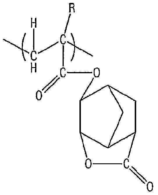
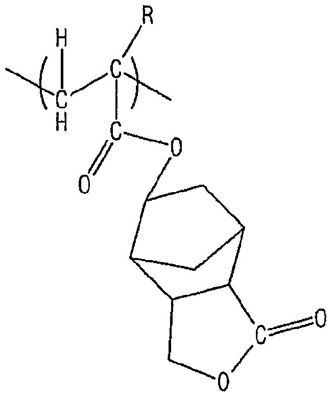


Claims
Priority Applications (10)
| Application Number | Priority Date | Filing Date | Title |
|---|---|---|---|
| KR1020057023108A KR100660792B1 (ko) | 2003-01-31 | 2004-01-27 | 침지 용매를 사용한 레지스트 조성물의 평가방법 |
| KR1020057023107A KR100660791B1 (ko) | 2003-01-31 | 2004-01-27 | 감도를 기초로 한 레지스트 조성물의 평가방법 |
| AT04705532T ATE529780T1 (de) | 2003-01-31 | 2004-01-27 | Resistzusammensetzung |
| CNB2004800029555A CN100565341C (zh) | 2003-01-31 | 2004-01-27 | 抗蚀剂组合物 |
| KR1020057013810A KR100743416B1 (ko) | 2003-01-31 | 2004-01-27 | 레지스트 조성물 |
| EP04705532A EP1589375B1 (en) | 2003-01-31 | 2004-01-27 | Resist composition |
| US10/845,620 US7501220B2 (en) | 2003-01-31 | 2004-05-13 | Resist composition |
| US11/621,896 US7527909B2 (en) | 2003-01-31 | 2007-01-10 | Resist composition |
| US11/621,895 US7541138B2 (en) | 2003-01-31 | 2007-01-10 | Resist composition |
| US12/252,319 US8198004B2 (en) | 2003-01-31 | 2008-10-15 | Resist composition |
Applications Claiming Priority (16)
| Application Number | Priority Date | Filing Date | Title |
|---|---|---|---|
| JP2003/25152 | 2003-01-31 | ||
| JP2003025152 | 2003-01-31 | ||
| JP2003045000 | 2003-02-21 | ||
| JP2003/45000 | 2003-02-21 | ||
| JP2003062531 | 2003-03-07 | ||
| JP2003/62531 | 2003-03-07 | ||
| JP2003125244 | 2003-04-30 | ||
| JP2003/125244 | 2003-04-30 | ||
| JP2003157257 | 2003-06-02 | ||
| JP2003/157257 | 2003-06-02 | ||
| JP2003/195403 | 2003-07-10 | ||
| JP2003195403 | 2003-07-10 | ||
| JP2003426939 | 2003-12-24 | ||
| JP2003/426939 | 2003-12-24 | ||
| JP2004017355A JP4434762B2 (ja) | 2003-01-31 | 2004-01-26 | レジスト組成物 |
| JP2004/17355 | 2004-01-26 |
Related Child Applications (1)
| Application Number | Title | Priority Date | Filing Date |
|---|---|---|---|
| US10/845,620 Continuation-In-Part US7501220B2 (en) | 2003-01-31 | 2004-05-13 | Resist composition |
Publications (1)
| Publication Number | Publication Date |
|---|---|
| WO2004068242A1 true WO2004068242A1 (ja) | 2004-08-12 |
Family
ID=32831263
Family Applications (1)
| Application Number | Title | Priority Date | Filing Date |
|---|---|---|---|
| PCT/JP2004/000704 WO2004068242A1 (ja) | 2003-01-31 | 2004-01-27 | レジスト組成物 |
Country Status (9)
| Country | Link |
|---|---|
| US (4) | US7501220B2 (ja) |
| EP (3) | EP1653285B1 (ja) |
| JP (1) | JP4434762B2 (ja) |
| KR (3) | KR100743416B1 (ja) |
| CN (3) | CN100523804C (ja) |
| AT (2) | ATE532103T1 (ja) |
| SG (1) | SG133444A1 (ja) |
| TW (3) | TWI338192B (ja) |
| WO (1) | WO2004068242A1 (ja) |
Cited By (73)
| Publication number | Priority date | Publication date | Assignee | Title |
|---|---|---|---|---|
| WO2005019937A1 (ja) * | 2003-08-25 | 2005-03-03 | Tokyo Ohka Kogyo Co., Ltd. | 液浸露光プロセス用レジスト保護膜形成用材料、該保護膜形成材料からなるレジスト保護膜、および該レジスト保護膜を用いたレジストパターン形成方法 |
| WO2005103098A1 (ja) * | 2004-04-27 | 2005-11-03 | Tokyo Ohka Kogyo Co., Ltd. | 液浸露光プロセス用レジスト保護膜形成用材料、および該保護膜を用いたレジストパターン形成方法 |
| WO2006027942A1 (ja) * | 2004-09-06 | 2006-03-16 | Tokyo Ohka Kogyo Co., Ltd. | 液浸露光プロセス用浸漬液および該浸漬液を用いたレジストパターン形成方法 |
| WO2006040949A1 (ja) * | 2004-10-12 | 2006-04-20 | Tokyo Ohka Kogyo Co., Ltd. | 液浸露光用ポジ型レジスト組成物およびレジストパターン形成方法 |
| WO2006067944A1 (ja) * | 2004-12-20 | 2006-06-29 | Tokyo Ohka Kogyo Co., Ltd. | 液浸露光用レジスト組成物およびレジストパターン形成方法 |
| EP1684119A2 (en) | 2005-01-24 | 2006-07-26 | Fuji Photo Film Co., Ltd. | Positive resist composition for immersion exposure and pattern-forming method using the same |
| EP1698937A2 (en) | 2005-03-04 | 2006-09-06 | Fuji Photo Film Co., Ltd. | Positive resist composition and pattern-forming method using the same |
| EP1757980A1 (en) | 2005-08-17 | 2007-02-28 | JSR Corporation | Radiation sensitive resin composition |
| EP1764649A2 (en) | 2005-09-20 | 2007-03-21 | FUJIFILM Corporation | Positive resist composition and pattern forming method using the same |
| EP1764647A2 (en) | 2005-08-19 | 2007-03-21 | FUJIFILM Corporation | Positive resist composition for immersion exposure and pattern-forming method using the same |
| WO2007058345A1 (ja) | 2005-11-21 | 2007-05-24 | Jsr Corporation | 感放射線性樹脂組成物 |
| WO2007116664A1 (ja) | 2006-03-31 | 2007-10-18 | Jsr Corporation | フッ素含有重合体及び精製方法並びに感放射線性樹脂組成物 |
| US7368220B2 (en) | 2005-12-09 | 2008-05-06 | Fujifilm Corporation | Positive resist composition and pattern forming method using the same |
| EP1975716A2 (en) | 2007-03-28 | 2008-10-01 | Fujifilm Corporation | Positive resist composition and pattern forming method |
| EP1975705A2 (en) | 2007-03-28 | 2008-10-01 | FUJIFILM Corporation | Positive resist composition and pattern-forming method |
| EP1975714A1 (en) | 2007-03-28 | 2008-10-01 | FUJIFILM Corporation | Positive resist composition and pattern forming method |
| EP2003504A2 (en) | 2007-06-12 | 2008-12-17 | FUJIFILM Corporation | Method of forming patterns |
| US7482112B2 (en) | 2006-01-23 | 2009-01-27 | Fujifilm Corporation | Pattern forming method |
| EP2019334A2 (en) | 2005-07-26 | 2009-01-28 | Fujifilm Corporation | Positive resist composition and method of pattern formation with the same |
| US7504194B2 (en) | 2005-12-09 | 2009-03-17 | Fujifilm Corporation | Positive resist composition and pattern making method using the same |
| EP2040122A2 (en) | 2005-09-13 | 2009-03-25 | Fujifilm Corporation | Positive resist composition and pattern-forming method using the same |
| US7524609B2 (en) | 2006-03-09 | 2009-04-28 | Fujifilm Corporation | Photo sensitive composition, pattern-forming method using the photosensitive composition and compound for use in the photosensitive composition |
| US7527911B2 (en) | 2006-02-20 | 2009-05-05 | Fujifilm Corporation | Photosensitive composition, pattern-forming method using the photosensitive composition and compounds used in the photosensitive composition |
| US7550250B2 (en) | 2005-12-27 | 2009-06-23 | Fujifilm Corporation | Positive resist composition and pattern forming method using the same |
| US7700260B2 (en) | 2006-01-23 | 2010-04-20 | Fujifilm Corporation | Pattern forming method |
| US7749679B2 (en) | 2005-12-28 | 2010-07-06 | Fujifilm Corporation | Photosensitive composition, pattern-forming method using the photosensitive composition and compounds used in the photosensitive composition |
| US7771912B2 (en) | 2005-12-09 | 2010-08-10 | Fujifilm Corporation | Positive resist composition and pattern forming method using the same |
| WO2010140637A1 (ja) | 2009-06-04 | 2010-12-09 | Jsr株式会社 | 感放射線性樹脂組成物、重合体及びレジストパターン形成方法 |
| KR20110008088A (ko) | 2008-05-19 | 2011-01-25 | 제이에스알 가부시끼가이샤 | 신규 화합물 및 중합체 및 감방사선성 조성물 |
| KR20110023837A (ko) | 2009-08-31 | 2011-03-08 | 후지필름 가부시키가이샤 | 감활성광선성 또는 감방사선성 수지 조성물 및 이것을 사용한 패턴형성방법 |
| US7951523B2 (en) | 2004-07-30 | 2011-05-31 | Tokyo Ohka Kogyo Co., Ltd. | Material for forming resist protective film and method for forming resist pattern using same |
| US7985534B2 (en) | 2007-05-15 | 2011-07-26 | Fujifilm Corporation | Pattern forming method |
| US7998655B2 (en) | 2007-06-12 | 2011-08-16 | Fujifilm Corporation | Method of forming patterns |
| US8017304B2 (en) | 2007-04-13 | 2011-09-13 | Fujifilm Corporation | Pattern forming method, and resist composition, developer and rinsing solution used in the pattern forming method |
| US8034547B2 (en) | 2007-04-13 | 2011-10-11 | Fujifilm Corporation | Pattern forming method, resist composition to be used in the pattern forming method, negative developing solution to be used in the pattern forming method and rinsing solution for negative development to be used in the pattern forming method |
| US8034537B2 (en) | 2007-03-28 | 2011-10-11 | Fujifilm Corporation | Positive resist composition and pattern forming method |
| US8053161B2 (en) | 2006-09-25 | 2011-11-08 | Fujifilm Corporation | Resist composition, resin for use in the resist composition, compound for use in the synthesis of the resin, and pattern-forming method using the resist composition |
| US8062826B2 (en) | 2007-03-28 | 2011-11-22 | Fujifilm Corporation | Positive resist composition and pattern-forming method |
| US8080363B2 (en) | 2007-03-20 | 2011-12-20 | Fujifilm Corporation | Resin for hydrophobitizing resist surface, method for manufacturing the resin, and positive resist composition containing the resin |
| US8097397B2 (en) | 2006-09-20 | 2012-01-17 | Tokyo Ohka Kogyo Co., Ltd. | Material for formation of protective film, method for formation of photoresist pattern, and solution for washing/removal of protective film |
| CN102344437A (zh) * | 2007-11-19 | 2012-02-08 | 东京应化工业株式会社 | 抗蚀剂组合物、抗蚀剂图案的形成方法、新型化合物以及产酸剂 |
| US8227183B2 (en) | 2006-12-25 | 2012-07-24 | Fujifilm Corporation | Pattern forming method, resist composition for multiple development used in the pattern forming method, developer for negative development used in the pattern forming method, and rinsing solution for negative development used in the pattern forming method |
| EP2485090A1 (en) | 2011-02-04 | 2012-08-08 | JSR Corporation | Radiation-sensitive resin composition for forming resist pattern |
| US8404427B2 (en) | 2005-12-28 | 2013-03-26 | Fujifilm Corporation | Photosensitive composition, and pattern-forming method and resist film using the photosensitive composition |
| US8409781B2 (en) | 2006-09-20 | 2013-04-02 | Tokyo Ohka Kogyo Co., Ltd. | Composition for formation of resist protection film, and method for formation of resist pattern using the same |
| US8426101B2 (en) | 2005-12-21 | 2013-04-23 | Fujifilm Corporation | Photosensitive composition, pattern-forming method using the photosensitve composition and compound in the photosensitive composition |
| US8450041B2 (en) | 2009-01-16 | 2013-05-28 | Fujifilm Corporation | Actinic ray-sensitive or radiation-sensitive resin composition and pattern forming method using the same |
| US8476001B2 (en) | 2007-05-15 | 2013-07-02 | Fujifilm Corporation | Pattern forming method |
| US8507172B2 (en) | 2007-01-31 | 2013-08-13 | Fujifilm Corporation | Positive resist composition and pattern forming method using the positive resist composition |
| US8507174B2 (en) | 2007-08-10 | 2013-08-13 | Fujifilm Corporation | Positive resist composition, pattern forming method using the composition, and compound for use in the composition |
| US8530148B2 (en) | 2006-12-25 | 2013-09-10 | Fujifilm Corporation | Pattern forming method, resist composition for multiple development used in the pattern forming method, developer for negative development used in the pattern forming method, and rinsing solution for negative development used in the pattern forming method |
| US8530692B2 (en) | 2009-02-23 | 2013-09-10 | Jsr Corporation | Compound, fluorine-containing polymer, radiation-sensitive resin composition and method for producing compound |
| US8557499B2 (en) | 2009-07-10 | 2013-10-15 | Fujifilm Corporation | Actinic-ray- or radiation-sensitive resin composition, compound and method of forming pattern using the composition |
| US8603733B2 (en) | 2007-04-13 | 2013-12-10 | Fujifilm Corporation | Pattern forming method, and resist composition, developer and rinsing solution used in the pattern forming method |
| US8617785B2 (en) | 2009-01-16 | 2013-12-31 | Fujifilm Corporation | Actinic ray-sensitive or radiation-sensitive resin composition and pattern forming method using the same |
| US8617794B2 (en) | 2007-06-12 | 2013-12-31 | Fujifilm Corporation | Method of forming patterns |
| US8632938B2 (en) | 2009-03-31 | 2014-01-21 | Fujifilm Corporation | Actinic-ray- or radiation-sensitive resin composition and method of forming pattern using the composition |
| US8632942B2 (en) | 2007-06-12 | 2014-01-21 | Fujifilm Corporation | Method of forming patterns |
| US8637229B2 (en) | 2006-12-25 | 2014-01-28 | Fujifilm Corporation | Pattern forming method, resist composition for multiple development used in the pattern forming method, developer for negative development used in the pattern forming method, and rinsing solution for negative development used in the pattern forming method |
| US8679724B2 (en) | 2005-12-09 | 2014-03-25 | Fujifilm Corporation | Positive resist composition, resin used for the positive resist composition, compound used for synthesis of the resin and pattern forming method using the positive resist composition |
| US8795954B2 (en) | 2010-10-15 | 2014-08-05 | Jsr Corporation | Resist pattern-forming method, and radiation-sensitive resin composition |
| US8815493B2 (en) | 2010-10-19 | 2014-08-26 | Jsr Corporation | Resist pattern-forming method, and radiation-sensitive resin composition |
| US8877421B2 (en) | 2007-03-28 | 2014-11-04 | Fujifilm Corporation | Positive resist composition and pattern-forming method |
| US8900789B2 (en) | 2008-07-14 | 2014-12-02 | Fujifilm Corporation | Actinic-ray- or radiation-sensitive resin composition and method of forming pattern using the composition |
| US9023579B2 (en) | 2009-07-10 | 2015-05-05 | Fujifilm Corporation | Actinic-ray- or radiation-sensitive resin composition, compound and method of forming pattern using the composition |
| US9034559B2 (en) | 2010-10-22 | 2015-05-19 | Jsr Corporation | Pattern-forming method, and radiation-sensitive composition |
| US9046782B2 (en) | 2007-06-12 | 2015-06-02 | Fujifilm Corporation | Resist composition for negative tone development and pattern forming method using the same |
| US9051403B2 (en) | 2007-09-21 | 2015-06-09 | Fujifilm Corporation | Photosensitive composition, pattern forming method using the photosensitive composition and compound for use in the photosensitive composition |
| US9164387B2 (en) | 2010-10-04 | 2015-10-20 | Jsr Corporation | Pattern-forming method, and radiation-sensitive resin composition |
| KR20170093927A (ko) | 2014-12-17 | 2017-08-16 | 후지필름 가부시키가이샤 | 패턴 형성 방법, 보호막 형성용 조성물 및 전자 디바이스의 제조 방법 |
| KR20180086494A (ko) | 2015-12-02 | 2018-07-31 | 후지필름 가부시키가이샤 | 패턴 형성 방법, 전자 디바이스의 제조 방법, 적층막 및 상층막 형성용 조성물 |
| US10175578B2 (en) | 2014-09-30 | 2019-01-08 | Fujifilm Corporation | Pattern forming method, composition for forming protective film, method for manufacturing electronic device, and electronic device |
| US10678132B2 (en) | 2007-03-14 | 2020-06-09 | Fujifilm Corporation | Resin for hydrophobilizing resist surface, method for production thereof, and positive resist composition containing the resin |
Families Citing this family (39)
| Publication number | Priority date | Publication date | Assignee | Title |
|---|---|---|---|---|
| JPWO2004077158A1 (ja) * | 2003-02-25 | 2006-06-08 | 東京応化工業株式会社 | ホトレジスト組成物およびレジストパターンの形成方法 |
| JP4772288B2 (ja) * | 2003-06-05 | 2011-09-14 | 東京応化工業株式会社 | ホトレジスト組成物用樹脂、ホトレジスト組成物、およびレジストパターン形成方法 |
| JP4188265B2 (ja) | 2003-10-23 | 2008-11-26 | 東京応化工業株式会社 | レジスト組成物およびレジストパターン形成方法 |
| JP4300131B2 (ja) * | 2004-02-16 | 2009-07-22 | 富士フイルム株式会社 | 液浸プロセス用化学増幅型レジスト組成物及びそれを用いたパターン形成方法 |
| JP4365236B2 (ja) | 2004-02-20 | 2009-11-18 | 富士フイルム株式会社 | 液浸露光用レジスト組成物及びそれを用いたパターン形成方法 |
| JP4264038B2 (ja) * | 2004-07-13 | 2009-05-13 | パナソニック株式会社 | 液浸露光用の液体及びパターン形成方法 |
| US7459261B2 (en) * | 2005-01-06 | 2008-12-02 | Shin-Etsu Chemical Co., Ltd. | Resist composition and patterning process using the same |
| JP5203575B2 (ja) * | 2005-05-04 | 2013-06-05 | ローム・アンド・ハース・エレクトロニック・マテリアルズ,エル.エル.シー. | コーティング組成物 |
| EP1898448A4 (en) * | 2005-06-29 | 2011-06-29 | Nikon Corp | EXPOSURE APPARATUS, METHOD FOR PROCESSING SUBSTRATE, AND METHOD FOR MANUFACTURING DEVICE |
| US7927779B2 (en) * | 2005-06-30 | 2011-04-19 | Taiwan Semiconductor Manufacturing Companym, Ltd. | Water mark defect prevention for immersion lithography |
| JP2007072155A (ja) * | 2005-09-07 | 2007-03-22 | Tokyo Ohka Kogyo Co Ltd | レジスト組成物およびレジストパターン形成方法 |
| JP4568668B2 (ja) * | 2005-09-22 | 2010-10-27 | 富士フイルム株式会社 | 液浸露光用ポジ型レジスト組成物及びそれを用いたパターン形成方法 |
| EP1783553A1 (en) * | 2005-11-07 | 2007-05-09 | Interuniversitair Microelektronica Centrum | Method of studying interaction between immersion fluid and substrate |
| JP2007133208A (ja) * | 2005-11-11 | 2007-05-31 | Tokyo Ohka Kogyo Co Ltd | ポジ型レジスト組成物およびレジストパターン形成方法 |
| US7629106B2 (en) * | 2005-11-16 | 2009-12-08 | Shin-Etsu Chemical Co., Ltd. | Resist composition and patterning process using the same |
| JP4717640B2 (ja) * | 2005-12-12 | 2011-07-06 | 東京応化工業株式会社 | 液浸露光用レジスト組成物およびレジストパターン形成方法 |
| US7538858B2 (en) * | 2006-01-11 | 2009-05-26 | Micron Technology, Inc. | Photolithographic systems and methods for producing sub-diffraction-limited features |
| TWI477909B (zh) | 2006-01-24 | 2015-03-21 | Fujifilm Corp | 正型感光性組成物及使用它之圖案形成方法 |
| US8034532B2 (en) | 2006-04-28 | 2011-10-11 | International Business Machines Corporation | High contact angle topcoat material and use thereof in lithography process |
| US7951524B2 (en) * | 2006-04-28 | 2011-05-31 | International Business Machines Corporation | Self-topcoating photoresist for photolithography |
| US8945808B2 (en) * | 2006-04-28 | 2015-02-03 | International Business Machines Corporation | Self-topcoating resist for photolithography |
| JP5189260B2 (ja) * | 2006-08-25 | 2013-04-24 | 三菱レイヨン株式会社 | 重合体の製造方法 |
| US8029972B2 (en) * | 2007-10-11 | 2011-10-04 | Tokyo Ohka Kogyo Co., Ltd. | Resist composition and method of forming resist pattern |
| JP5555914B2 (ja) * | 2007-10-29 | 2014-07-23 | Jsr株式会社 | 感放射線性樹脂組成物 |
| JP5398248B2 (ja) | 2008-02-06 | 2014-01-29 | 東京応化工業株式会社 | 液浸露光用レジスト組成物およびそれを用いたレジストパターン形成方法 |
| JP5150296B2 (ja) * | 2008-02-13 | 2013-02-20 | 富士フイルム株式会社 | 電子線、x線またはeuv用ポジ型レジスト組成物及びこれを用いたパターン形成方法 |
| JP2009224374A (ja) * | 2008-03-13 | 2009-10-01 | Oki Semiconductor Co Ltd | Peb装置及びその制御方法 |
| JP5427447B2 (ja) * | 2008-03-28 | 2014-02-26 | 富士フイルム株式会社 | ポジ型感光性組成物及びそれを用いたパターン形成方法 |
| JP5172494B2 (ja) * | 2008-06-23 | 2013-03-27 | 東京応化工業株式会社 | 液浸露光用レジスト組成物、レジストパターン形成方法、含フッ素高分子化合物 |
| JP2010085605A (ja) * | 2008-09-30 | 2010-04-15 | Hitachi Chem Co Ltd | 感光性樹脂組成物、これを用いた感光性エレメント、レジストパターンの形成方法及びプリント配線板の製造方法 |
| JP5386236B2 (ja) | 2009-06-01 | 2014-01-15 | 東京応化工業株式会社 | ポジ型レジスト組成物及びレジストパターン形成方法 |
| JP5568258B2 (ja) | 2009-07-03 | 2014-08-06 | 東京応化工業株式会社 | ポジ型レジスト組成物およびそれを用いたレジストパターン形成方法、並びに含フッ素高分子化合物 |
| JP5645510B2 (ja) * | 2009-07-10 | 2014-12-24 | 富士フイルム株式会社 | 感活性光線性または感放射線性樹脂組成物およびこれを用いたパターン形成方法 |
| JP5505371B2 (ja) * | 2010-06-01 | 2014-05-28 | 信越化学工業株式会社 | 高分子化合物、化学増幅ポジ型レジスト材料、及びパターン形成方法 |
| JP6864994B2 (ja) | 2015-06-26 | 2021-04-28 | 住友化学株式会社 | レジスト組成物 |
| JP6883954B2 (ja) | 2015-06-26 | 2021-06-09 | 住友化学株式会社 | レジスト組成物 |
| JP6782102B2 (ja) | 2015-06-26 | 2020-11-11 | 住友化学株式会社 | レジスト組成物 |
| JP6796534B2 (ja) * | 2017-03-31 | 2020-12-09 | 東京応化工業株式会社 | レジスト組成物及びレジストパターン形成方法 |
| CN111205385A (zh) * | 2020-02-28 | 2020-05-29 | 宁波南大光电材料有限公司 | 含酸抑制剂的改性成膜树脂及其制备方法与光刻胶组合物 |
Citations (7)
| Publication number | Priority date | Publication date | Assignee | Title |
|---|---|---|---|---|
| JPH06265326A (ja) * | 1993-03-16 | 1994-09-20 | Kawasaki Steel Corp | 2次元距離計を用いた板幅・蛇行測定装置の校正装置 |
| JPH11176727A (ja) * | 1997-12-11 | 1999-07-02 | Nikon Corp | 投影露光装置 |
| WO1999049504A1 (fr) * | 1998-03-26 | 1999-09-30 | Nikon Corporation | Procede et systeme d'exposition par projection |
| US6444397B2 (en) * | 1998-11-10 | 2002-09-03 | Tokyo Ohka Kogyo Co., Ltd. | Negative-working photoresist composition |
| JP2002303980A (ja) * | 2001-04-06 | 2002-10-18 | Fuji Photo Film Co Ltd | ポジ型フォトレジスト組成物 |
| US6479211B1 (en) * | 1999-05-26 | 2002-11-12 | Fuji Photo Film Co., Ltd. | Positive photoresist composition for far ultraviolet exposure |
| US6495306B2 (en) * | 1999-12-22 | 2002-12-17 | Sumitomo Chemical Company, Limited | Chemically amplified positive resist composition |
Family Cites Families (50)
| Publication number | Priority date | Publication date | Assignee | Title |
|---|---|---|---|---|
| JPS5353314A (en) | 1976-10-26 | 1978-05-15 | Agency Of Ind Science & Technol | Sensitive high polymer composition and picture imae forming method usingsaid composition |
| US4276365A (en) * | 1979-07-02 | 1981-06-30 | Fujitsu Limited | Positive resist terpolymer composition and method of forming resist pattern |
| JPS6265326A (ja) | 1985-09-18 | 1987-03-24 | Hitachi Ltd | 露光装置 |
| JPS6265352A (ja) | 1985-09-18 | 1987-03-24 | Hitachi Ltd | 電子装置 |
| JPS62134644A (ja) | 1985-12-06 | 1987-06-17 | Fujitsu Ltd | ポジ型レジスト組成物 |
| US4792353A (en) | 1986-10-10 | 1988-12-20 | Massachusetts Institute Of Technology | Aluminum oxide-metal compositions |
| JP2653148B2 (ja) * | 1989-01-20 | 1997-09-10 | 富士通株式会社 | レジスト組成物 |
| JP2753930B2 (ja) * | 1992-11-27 | 1998-05-20 | キヤノン株式会社 | 液浸式投影露光装置 |
| KR960015081A (ko) * | 1993-07-15 | 1996-05-22 | 마쯔모또 에이이찌 | 화학증폭형 레지스트 조성물 |
| JP3438287B2 (ja) | 1994-01-20 | 2003-08-18 | 富士通株式会社 | レジストの品質管理方法 |
| KR100255706B1 (ko) * | 1995-10-27 | 2000-05-01 | 나까니시 히로유끼 | 반방향족 폴리아미드 제조방법 |
| KR100253575B1 (ko) * | 1996-06-24 | 2000-04-15 | 김영환 | 포토레지스트 |
| KR0183901B1 (ko) * | 1996-07-03 | 1999-04-01 | 삼성전자 주식회사 | 레지스트 조성물 |
| US5929271A (en) * | 1996-08-20 | 1999-07-27 | Tokyo Ohka Kogyo Co., Ltd. | Compounds for use in a positive-working resist composition |
| TW490593B (en) | 1996-10-16 | 2002-06-11 | Sumitomo Chemical Co | Positive resist composition |
| TW495535B (en) * | 1997-01-28 | 2002-07-21 | Hitachi Chemical Co Ltd | Epoxy resin composition for semiconductor sealing |
| TW383414B (en) * | 1997-03-05 | 2000-03-01 | Tokyo Electron Ltd | Photoresist agent processing method and photoresist agent processing system and evaluation method and processing apparatus for photoresist agent film |
| JP3307853B2 (ja) | 1997-05-30 | 2002-07-24 | 東京エレクトロン株式会社 | 膜厚評価方法および処理装置 |
| US6077643A (en) | 1997-08-28 | 2000-06-20 | Shipley Company, L.L.C. | Polymers and photoresist compositions |
| US6057083A (en) * | 1997-11-04 | 2000-05-02 | Shipley Company, L.L.C. | Polymers and photoresist compositions |
| KR19990045397A (ko) | 1997-11-17 | 1999-06-25 | 고오사이 아끼오 | 레지스트 패턴 형성법 및 이 방법에 사용되는포지티브 레지스트 조성물 |
| JP3859353B2 (ja) | 1998-04-28 | 2006-12-20 | 富士通株式会社 | ネガ型レジスト組成物およびレジストパターンの形成方法 |
| WO2000001684A1 (fr) | 1998-07-03 | 2000-01-13 | Nec Corporation | Derives de (meth)acrylate porteurs d'une structure lactone, compositions polymeres et photoresists et procede de formation de modeles a l'aide de ceux-ci |
| JP3042618B2 (ja) | 1998-07-03 | 2000-05-15 | 日本電気株式会社 | ラクトン構造を有する(メタ)アクリレート誘導体、重合体、フォトレジスト組成物、及びパターン形成方法 |
| JP2000058436A (ja) * | 1998-08-11 | 2000-02-25 | Nikon Corp | 投影露光装置及び露光方法 |
| JP3876571B2 (ja) * | 1998-08-26 | 2007-01-31 | 住友化学株式会社 | 化学増幅型ポジ型レジスト組成物 |
| CN1190706C (zh) * | 1998-08-26 | 2005-02-23 | 住友化学工业株式会社 | 一种化学增强型正光刻胶组合物 |
| US6303266B1 (en) * | 1998-09-24 | 2001-10-16 | Kabushiki Kaisha Toshiba | Resin useful for resist, resist composition and pattern forming process using the same |
| JP2000121498A (ja) | 1998-10-15 | 2000-04-28 | Nikon Corp | 結像性能の評価方法及び装置 |
| TWI263866B (en) * | 1999-01-18 | 2006-10-11 | Sumitomo Chemical Co | Chemical amplification type positive resist composition |
| EP1083445A4 (en) | 1999-03-31 | 2006-03-29 | Daicel Chem | ILLUMINATING FILM, ILLUMINATING COMPOSITE FILM AND LIQUID CRYSTAL DISPLAY |
| JP3547047B2 (ja) | 1999-05-26 | 2004-07-28 | 富士写真フイルム株式会社 | 遠紫外線露光用ポジ型フォトレジスト組成物 |
| US6461789B1 (en) * | 1999-08-25 | 2002-10-08 | Shin-Etsu Chemical Co., Ltd. | Polymers, chemical amplification resist compositions and patterning process |
| JP4061801B2 (ja) * | 2000-01-24 | 2008-03-19 | 住友化学株式会社 | 化学増幅型ポジ型レジスト組成物 |
| JP3416618B2 (ja) * | 2000-06-07 | 2003-06-16 | 株式会社半導体先端テクノロジーズ | 薄膜評価方法および薄膜評価装置 |
| JP2002043215A (ja) | 2000-07-28 | 2002-02-08 | Sharp Corp | レジストパターン形成方法および半導体製造装置および半導体装置および携帯情報端末 |
| JP2002057093A (ja) | 2000-08-11 | 2002-02-22 | Tokyo Electron Ltd | 現像処理の評価方法、レジストパタ−ン形成方法及びレジストパタ−ン形成システム |
| JP4441104B2 (ja) * | 2000-11-27 | 2010-03-31 | 東京応化工業株式会社 | ポジ型レジスト組成物 |
| JP3945741B2 (ja) * | 2000-12-04 | 2007-07-18 | 東京応化工業株式会社 | ポジ型レジスト組成物 |
| JP3991191B2 (ja) * | 2001-06-14 | 2007-10-17 | 信越化学工業株式会社 | ラクトン構造を有する新規(メタ)アクリレート化合物、重合体、フォトレジスト材料、及びパターン形成法 |
| JP3803286B2 (ja) | 2001-12-03 | 2006-08-02 | 東京応化工業株式会社 | ポジ型レジスト組成物及びレジストパターンの形成方法 |
| JP3841399B2 (ja) * | 2002-02-21 | 2006-11-01 | 富士写真フイルム株式会社 | ポジ型レジスト組成物 |
| US6781670B2 (en) | 2002-12-30 | 2004-08-24 | Intel Corporation | Immersion lithography |
| JP4121388B2 (ja) | 2003-01-30 | 2008-07-23 | 富士フイルム株式会社 | ポジ型レジスト組成物、及び、活性光線の照射により酸を発生する化合物 |
| JP4146755B2 (ja) * | 2003-05-09 | 2008-09-10 | 松下電器産業株式会社 | パターン形成方法 |
| JP4084712B2 (ja) * | 2003-06-23 | 2008-04-30 | 松下電器産業株式会社 | パターン形成方法 |
| US6809794B1 (en) * | 2003-06-27 | 2004-10-26 | Asml Holding N.V. | Immersion photolithography system and method using inverted wafer-projection optics interface |
| US6844206B1 (en) * | 2003-08-21 | 2005-01-18 | Advanced Micro Devices, Llp | Refractive index system monitor and control for immersion lithography |
| JP4235810B2 (ja) * | 2003-10-23 | 2009-03-11 | 信越化学工業株式会社 | 高分子化合物、レジスト材料及びパターン形成方法 |
| KR100557222B1 (ko) | 2004-04-28 | 2006-03-07 | 동부아남반도체 주식회사 | 이머전 리소그라피 공정의 액체 제거 장치 및 방법 |
-
2004
- 2004-01-26 JP JP2004017355A patent/JP4434762B2/ja not_active Expired - Lifetime
- 2004-01-27 EP EP05111463.5A patent/EP1653285B1/en not_active Expired - Lifetime
- 2004-01-27 AT AT05111460T patent/ATE532103T1/de active
- 2004-01-27 KR KR1020057013810A patent/KR100743416B1/ko active IP Right Grant
- 2004-01-27 KR KR1020057023108A patent/KR100660792B1/ko active IP Right Grant
- 2004-01-27 KR KR1020057023107A patent/KR100660791B1/ko active IP Right Grant
- 2004-01-27 AT AT04705532T patent/ATE529780T1/de not_active IP Right Cessation
- 2004-01-27 EP EP05111460A patent/EP1653284B1/en not_active Expired - Lifetime
- 2004-01-27 CN CNB2005101375937A patent/CN100523804C/zh not_active Expired - Fee Related
- 2004-01-27 CN CNB2005101375922A patent/CN100533143C/zh not_active Expired - Fee Related
- 2004-01-27 CN CNB2004800029555A patent/CN100565341C/zh not_active Expired - Fee Related
- 2004-01-27 WO PCT/JP2004/000704 patent/WO2004068242A1/ja active Application Filing
- 2004-01-27 EP EP04705532A patent/EP1589375B1/en not_active Expired - Lifetime
- 2004-01-27 SG SG200508430-6A patent/SG133444A1/en unknown
- 2004-01-29 TW TW094123917A patent/TWI338192B/zh not_active IP Right Cessation
- 2004-01-29 TW TW093102028A patent/TWI304518B/zh not_active IP Right Cessation
- 2004-01-29 TW TW094123914A patent/TWI317461B/zh not_active IP Right Cessation
- 2004-05-13 US US10/845,620 patent/US7501220B2/en not_active Expired - Lifetime
-
2007
- 2007-01-10 US US11/621,895 patent/US7541138B2/en not_active Expired - Lifetime
- 2007-01-10 US US11/621,896 patent/US7527909B2/en active Active
-
2008
- 2008-10-15 US US12/252,319 patent/US8198004B2/en not_active Expired - Lifetime
Patent Citations (7)
| Publication number | Priority date | Publication date | Assignee | Title |
|---|---|---|---|---|
| JPH06265326A (ja) * | 1993-03-16 | 1994-09-20 | Kawasaki Steel Corp | 2次元距離計を用いた板幅・蛇行測定装置の校正装置 |
| JPH11176727A (ja) * | 1997-12-11 | 1999-07-02 | Nikon Corp | 投影露光装置 |
| WO1999049504A1 (fr) * | 1998-03-26 | 1999-09-30 | Nikon Corporation | Procede et systeme d'exposition par projection |
| US6444397B2 (en) * | 1998-11-10 | 2002-09-03 | Tokyo Ohka Kogyo Co., Ltd. | Negative-working photoresist composition |
| US6479211B1 (en) * | 1999-05-26 | 2002-11-12 | Fuji Photo Film Co., Ltd. | Positive photoresist composition for far ultraviolet exposure |
| US6495306B2 (en) * | 1999-12-22 | 2002-12-17 | Sumitomo Chemical Company, Limited | Chemically amplified positive resist composition |
| JP2002303980A (ja) * | 2001-04-06 | 2002-10-18 | Fuji Photo Film Co Ltd | ポジ型フォトレジスト組成物 |
Cited By (125)
| Publication number | Priority date | Publication date | Assignee | Title |
|---|---|---|---|---|
| WO2005019937A1 (ja) * | 2003-08-25 | 2005-03-03 | Tokyo Ohka Kogyo Co., Ltd. | 液浸露光プロセス用レジスト保護膜形成用材料、該保護膜形成材料からなるレジスト保護膜、および該レジスト保護膜を用いたレジストパターン形成方法 |
| WO2005103098A1 (ja) * | 2004-04-27 | 2005-11-03 | Tokyo Ohka Kogyo Co., Ltd. | 液浸露光プロセス用レジスト保護膜形成用材料、および該保護膜を用いたレジストパターン形成方法 |
| US7846637B2 (en) | 2004-04-27 | 2010-12-07 | Tokyo Ohka Kogyo Co., Ltd. | Material for forming resist protective film for use in liquid immersion lithography process and method for forming resist pattern using the protective film |
| US7951523B2 (en) | 2004-07-30 | 2011-05-31 | Tokyo Ohka Kogyo Co., Ltd. | Material for forming resist protective film and method for forming resist pattern using same |
| WO2006027942A1 (ja) * | 2004-09-06 | 2006-03-16 | Tokyo Ohka Kogyo Co., Ltd. | 液浸露光プロセス用浸漬液および該浸漬液を用いたレジストパターン形成方法 |
| WO2006040949A1 (ja) * | 2004-10-12 | 2006-04-20 | Tokyo Ohka Kogyo Co., Ltd. | 液浸露光用ポジ型レジスト組成物およびレジストパターン形成方法 |
| WO2006067944A1 (ja) * | 2004-12-20 | 2006-06-29 | Tokyo Ohka Kogyo Co., Ltd. | 液浸露光用レジスト組成物およびレジストパターン形成方法 |
| JP2006171656A (ja) * | 2004-12-20 | 2006-06-29 | Tokyo Ohka Kogyo Co Ltd | 液浸露光用レジスト組成物およびレジストパターン形成方法 |
| JP4597655B2 (ja) * | 2004-12-20 | 2010-12-15 | 東京応化工業株式会社 | レジストパターン形成方法 |
| US7947421B2 (en) | 2005-01-24 | 2011-05-24 | Fujifilm Corporation | Positive resist composition for immersion exposure and pattern-forming method using the same |
| EP1684119A2 (en) | 2005-01-24 | 2006-07-26 | Fuji Photo Film Co., Ltd. | Positive resist composition for immersion exposure and pattern-forming method using the same |
| EP1698937A2 (en) | 2005-03-04 | 2006-09-06 | Fuji Photo Film Co., Ltd. | Positive resist composition and pattern-forming method using the same |
| US8741537B2 (en) | 2005-03-04 | 2014-06-03 | Fujifilm Corporation | Positive resist composition and pattern-forming method using the same |
| EP2020618A2 (en) | 2005-07-26 | 2009-02-04 | Fujifilm Corporation | Positive resist composition and method of pattern formation with the same |
| US9835945B2 (en) | 2005-07-26 | 2017-12-05 | Fujifilm Corporation | Positive resist composition and method of pattern formation with the same |
| US9541831B2 (en) | 2005-07-26 | 2017-01-10 | Fujifilm Corporation | Positive resist composition and method of pattern formation with the same |
| US8871421B2 (en) | 2005-07-26 | 2014-10-28 | Fujifilm Corporation | Positive resist composition and method of pattern formation with the same |
| US9057952B2 (en) | 2005-07-26 | 2015-06-16 | Fujifilm Corporation | Positive resist composition and method of pattern formation with the same |
| EP2019334A2 (en) | 2005-07-26 | 2009-01-28 | Fujifilm Corporation | Positive resist composition and method of pattern formation with the same |
| EP1757980A1 (en) | 2005-08-17 | 2007-02-28 | JSR Corporation | Radiation sensitive resin composition |
| EP1764647A2 (en) | 2005-08-19 | 2007-03-21 | FUJIFILM Corporation | Positive resist composition for immersion exposure and pattern-forming method using the same |
| US7803511B2 (en) | 2005-08-19 | 2010-09-28 | Fujifilm Corporation | Positive resist composition for immersion exposure and pattern-forming method using the same |
| US8808975B2 (en) | 2005-08-19 | 2014-08-19 | Fujifilm Corporation | Positive resist composition for immersion exposure and pattern-forming method using the same |
| US7611820B2 (en) | 2005-09-13 | 2009-11-03 | Fujifilm Corporation | Positive resist composition and pattern-forming method using the same |
| EP2040122A2 (en) | 2005-09-13 | 2009-03-25 | Fujifilm Corporation | Positive resist composition and pattern-forming method using the same |
| US7674567B2 (en) | 2005-09-20 | 2010-03-09 | Fujifilm Corporation | Positive resist composition and pattern forming method using the same |
| EP1764649A2 (en) | 2005-09-20 | 2007-03-21 | FUJIFILM Corporation | Positive resist composition and pattern forming method using the same |
| WO2007058345A1 (ja) | 2005-11-21 | 2007-05-24 | Jsr Corporation | 感放射線性樹脂組成物 |
| US9709891B2 (en) | 2005-12-09 | 2017-07-18 | Fujifilm Corporation | Positive resist composition, resin used for the positive resist composition, compound used for synthesis of the resin and pattern forming method using the positive resist composition |
| US8697329B2 (en) | 2005-12-09 | 2014-04-15 | Fujifilm Corporation | Positive resist composition and pattern forming method using the same |
| US7368220B2 (en) | 2005-12-09 | 2008-05-06 | Fujifilm Corporation | Positive resist composition and pattern forming method using the same |
| US8679724B2 (en) | 2005-12-09 | 2014-03-25 | Fujifilm Corporation | Positive resist composition, resin used for the positive resist composition, compound used for synthesis of the resin and pattern forming method using the positive resist composition |
| US7771912B2 (en) | 2005-12-09 | 2010-08-10 | Fujifilm Corporation | Positive resist composition and pattern forming method using the same |
| EP3537217A2 (en) | 2005-12-09 | 2019-09-11 | FUJIFILM Corporation | Positive resist composition, resin used for the positive resist composition, compound used for synthesis of the resin and pattern forming method using the positive resist composition |
| US7790351B2 (en) | 2005-12-09 | 2010-09-07 | Fujifilm Corporation | Positive resist composition and pattern making method using the same |
| US9081279B2 (en) | 2005-12-09 | 2015-07-14 | Fujifilm Corporation | Positive resist composition, resin used for the positive resist composition, compound used for synthesis of the resin and pattern forming method using the positive resist composition |
| US7504194B2 (en) | 2005-12-09 | 2009-03-17 | Fujifilm Corporation | Positive resist composition and pattern making method using the same |
| US8426101B2 (en) | 2005-12-21 | 2013-04-23 | Fujifilm Corporation | Photosensitive composition, pattern-forming method using the photosensitve composition and compound in the photosensitive composition |
| US7785767B2 (en) | 2005-12-27 | 2010-08-31 | Fujifilm Corporation | Positive resist composition and pattern forming method using the same |
| US7550250B2 (en) | 2005-12-27 | 2009-06-23 | Fujifilm Corporation | Positive resist composition and pattern forming method using the same |
| US8404427B2 (en) | 2005-12-28 | 2013-03-26 | Fujifilm Corporation | Photosensitive composition, and pattern-forming method and resist film using the photosensitive composition |
| US7749679B2 (en) | 2005-12-28 | 2010-07-06 | Fujifilm Corporation | Photosensitive composition, pattern-forming method using the photosensitive composition and compounds used in the photosensitive composition |
| US8389200B2 (en) | 2006-01-23 | 2013-03-05 | Fujifilm Corporation | Pattern forming method |
| US7842452B2 (en) | 2006-01-23 | 2010-11-30 | Fujifilm Corporation | Pattern forming method |
| US7700260B2 (en) | 2006-01-23 | 2010-04-20 | Fujifilm Corporation | Pattern forming method |
| US7482112B2 (en) | 2006-01-23 | 2009-01-27 | Fujifilm Corporation | Pattern forming method |
| US7527911B2 (en) | 2006-02-20 | 2009-05-05 | Fujifilm Corporation | Photosensitive composition, pattern-forming method using the photosensitive composition and compounds used in the photosensitive composition |
| US7524609B2 (en) | 2006-03-09 | 2009-04-28 | Fujifilm Corporation | Photo sensitive composition, pattern-forming method using the photosensitive composition and compound for use in the photosensitive composition |
| US11036133B2 (en) | 2006-03-31 | 2021-06-15 | Jsr Corporation | Fluorine-containing polymer, purification method, and radiation-sensitive resin composition |
| US11681222B2 (en) | 2006-03-31 | 2023-06-20 | Jsr Corporation | Fluorine-containing polymer, purification method, and radiation-sensitive resin composition |
| US9213236B2 (en) | 2006-03-31 | 2015-12-15 | Jsr Corporation | Fluorine-containing polymer, purification method, and radiation-sensitive resin composition |
| US9500950B2 (en) | 2006-03-31 | 2016-11-22 | Jsr Corporation | Fluorine-containing polymer, purification method, and radiation-sensitive resin composition |
| WO2007116664A1 (ja) | 2006-03-31 | 2007-10-18 | Jsr Corporation | フッ素含有重合体及び精製方法並びに感放射線性樹脂組成物 |
| US8697343B2 (en) | 2006-03-31 | 2014-04-15 | Jsr Corporation | Fluorine-containing polymer, purification method, and radiation-sensitive resin composition |
| US10620534B2 (en) | 2006-03-31 | 2020-04-14 | Jsr Corporation | Fluorine-containing polymer, purification method, and radiation-sensitive resin composition |
| US10082733B2 (en) | 2006-03-31 | 2018-09-25 | Jsr Corporation | Fluorine-containing polymer, purification method, and radiation-sensitive resin composition |
| US8409781B2 (en) | 2006-09-20 | 2013-04-02 | Tokyo Ohka Kogyo Co., Ltd. | Composition for formation of resist protection film, and method for formation of resist pattern using the same |
| US8097397B2 (en) | 2006-09-20 | 2012-01-17 | Tokyo Ohka Kogyo Co., Ltd. | Material for formation of protective film, method for formation of photoresist pattern, and solution for washing/removal of protective film |
| US8053161B2 (en) | 2006-09-25 | 2011-11-08 | Fujifilm Corporation | Resist composition, resin for use in the resist composition, compound for use in the synthesis of the resin, and pattern-forming method using the resist composition |
| US8951718B2 (en) | 2006-12-25 | 2015-02-10 | Fujifilm Corporation | Pattern forming method, resist composition for multiple development used in the pattern forming method, developer for negative development used in the pattern forming method, and rinsing solution for negative development used in the pattern forming method |
| US9465298B2 (en) | 2006-12-25 | 2016-10-11 | Fujifilm Corporation | Pattern forming method, resist composition for multiple development used in the pattern forming method, developer for negative development used in the pattern forming method, and rinsing solution for negative development used in the pattern forming method |
| US9291904B2 (en) | 2006-12-25 | 2016-03-22 | Fujifilm Corporation | Pattern forming method, resist composition for multiple development used in the pattern forming method, developer for negative development used in the pattern forming method, and rinsing solution for negative development used in the pattern forming method |
| US8637229B2 (en) | 2006-12-25 | 2014-01-28 | Fujifilm Corporation | Pattern forming method, resist composition for multiple development used in the pattern forming method, developer for negative development used in the pattern forming method, and rinsing solution for negative development used in the pattern forming method |
| US8227183B2 (en) | 2006-12-25 | 2012-07-24 | Fujifilm Corporation | Pattern forming method, resist composition for multiple development used in the pattern forming method, developer for negative development used in the pattern forming method, and rinsing solution for negative development used in the pattern forming method |
| US8530148B2 (en) | 2006-12-25 | 2013-09-10 | Fujifilm Corporation | Pattern forming method, resist composition for multiple development used in the pattern forming method, developer for negative development used in the pattern forming method, and rinsing solution for negative development used in the pattern forming method |
| US8507172B2 (en) | 2007-01-31 | 2013-08-13 | Fujifilm Corporation | Positive resist composition and pattern forming method using the positive resist composition |
| US10678132B2 (en) | 2007-03-14 | 2020-06-09 | Fujifilm Corporation | Resin for hydrophobilizing resist surface, method for production thereof, and positive resist composition containing the resin |
| US8080363B2 (en) | 2007-03-20 | 2011-12-20 | Fujifilm Corporation | Resin for hydrophobitizing resist surface, method for manufacturing the resin, and positive resist composition containing the resin |
| US8034537B2 (en) | 2007-03-28 | 2011-10-11 | Fujifilm Corporation | Positive resist composition and pattern forming method |
| US8062826B2 (en) | 2007-03-28 | 2011-11-22 | Fujifilm Corporation | Positive resist composition and pattern-forming method |
| EP1975716A2 (en) | 2007-03-28 | 2008-10-01 | Fujifilm Corporation | Positive resist composition and pattern forming method |
| US7666574B2 (en) | 2007-03-28 | 2010-02-23 | Fujifilm Corporation | Positive resist composition and pattern forming method |
| EP1975714A1 (en) | 2007-03-28 | 2008-10-01 | FUJIFILM Corporation | Positive resist composition and pattern forming method |
| US8343708B2 (en) | 2007-03-28 | 2013-01-01 | Fujifilm Corporation | Positive resist composition and pattern forming method |
| US7635554B2 (en) | 2007-03-28 | 2009-12-22 | Fujifilm Corporation | Positive resist composition and pattern forming method |
| US8877421B2 (en) | 2007-03-28 | 2014-11-04 | Fujifilm Corporation | Positive resist composition and pattern-forming method |
| EP1975705A2 (en) | 2007-03-28 | 2008-10-01 | FUJIFILM Corporation | Positive resist composition and pattern-forming method |
| US8241840B2 (en) | 2007-04-13 | 2012-08-14 | Fujifilm Corporation | Pattern forming method, resist composition to be used in the pattern forming method, negative developing solution to be used in the pattern forming method and rinsing solution for negative development to be used in the pattern forming method |
| US8017304B2 (en) | 2007-04-13 | 2011-09-13 | Fujifilm Corporation | Pattern forming method, and resist composition, developer and rinsing solution used in the pattern forming method |
| US8034547B2 (en) | 2007-04-13 | 2011-10-11 | Fujifilm Corporation | Pattern forming method, resist composition to be used in the pattern forming method, negative developing solution to be used in the pattern forming method and rinsing solution for negative development to be used in the pattern forming method |
| US8603733B2 (en) | 2007-04-13 | 2013-12-10 | Fujifilm Corporation | Pattern forming method, and resist composition, developer and rinsing solution used in the pattern forming method |
| US8476001B2 (en) | 2007-05-15 | 2013-07-02 | Fujifilm Corporation | Pattern forming method |
| US7985534B2 (en) | 2007-05-15 | 2011-07-26 | Fujifilm Corporation | Pattern forming method |
| EP2579098A1 (en) | 2007-06-12 | 2013-04-10 | Fujifilm Corporation | Method of forming patterns |
| US8617794B2 (en) | 2007-06-12 | 2013-12-31 | Fujifilm Corporation | Method of forming patterns |
| US7998655B2 (en) | 2007-06-12 | 2011-08-16 | Fujifilm Corporation | Method of forming patterns |
| US8632942B2 (en) | 2007-06-12 | 2014-01-21 | Fujifilm Corporation | Method of forming patterns |
| US8017298B2 (en) | 2007-06-12 | 2011-09-13 | Fujifilm Corporation | Method of forming patterns |
| US8071272B2 (en) | 2007-06-12 | 2011-12-06 | Fujifilm Corporation | Method of forming patterns |
| US8088557B2 (en) | 2007-06-12 | 2012-01-03 | Fujifilm Corporation | Method of forming patterns |
| US8852847B2 (en) | 2007-06-12 | 2014-10-07 | Fujifilm Corporation | Method of forming patterns |
| US9176386B2 (en) | 2007-06-12 | 2015-11-03 | Fujifilm Corporation | Method of forming patterns |
| EP2003504A2 (en) | 2007-06-12 | 2008-12-17 | FUJIFILM Corporation | Method of forming patterns |
| US8895225B2 (en) | 2007-06-12 | 2014-11-25 | Fujifilm Corporation | Method of forming patterns |
| US9046782B2 (en) | 2007-06-12 | 2015-06-02 | Fujifilm Corporation | Resist composition for negative tone development and pattern forming method using the same |
| US9458343B2 (en) | 2007-06-12 | 2016-10-04 | Fujifilm Corporation | Method of forming patterns |
| US8507174B2 (en) | 2007-08-10 | 2013-08-13 | Fujifilm Corporation | Positive resist composition, pattern forming method using the composition, and compound for use in the composition |
| US9051403B2 (en) | 2007-09-21 | 2015-06-09 | Fujifilm Corporation | Photosensitive composition, pattern forming method using the photosensitive composition and compound for use in the photosensitive composition |
| CN102344437A (zh) * | 2007-11-19 | 2012-02-08 | 东京应化工业株式会社 | 抗蚀剂组合物、抗蚀剂图案的形成方法、新型化合物以及产酸剂 |
| KR20110008088A (ko) | 2008-05-19 | 2011-01-25 | 제이에스알 가부시끼가이샤 | 신규 화합물 및 중합체 및 감방사선성 조성물 |
| US8697331B2 (en) | 2008-05-19 | 2014-04-15 | Jsr Corporation | Compound, polymer, and radiation-sensitive composition |
| US8900789B2 (en) | 2008-07-14 | 2014-12-02 | Fujifilm Corporation | Actinic-ray- or radiation-sensitive resin composition and method of forming pattern using the composition |
| KR20160141379A (ko) | 2008-07-14 | 2016-12-08 | 후지필름 가부시키가이샤 | 감활성 광선성 또는 감방사선성 수지 조성물, 및 상기 조성물을 이용한 패턴 형성 방법 |
| US8450041B2 (en) | 2009-01-16 | 2013-05-28 | Fujifilm Corporation | Actinic ray-sensitive or radiation-sensitive resin composition and pattern forming method using the same |
| US8617785B2 (en) | 2009-01-16 | 2013-12-31 | Fujifilm Corporation | Actinic ray-sensitive or radiation-sensitive resin composition and pattern forming method using the same |
| US8530692B2 (en) | 2009-02-23 | 2013-09-10 | Jsr Corporation | Compound, fluorine-containing polymer, radiation-sensitive resin composition and method for producing compound |
| US8632938B2 (en) | 2009-03-31 | 2014-01-21 | Fujifilm Corporation | Actinic-ray- or radiation-sensitive resin composition and method of forming pattern using the composition |
| WO2010140637A1 (ja) | 2009-06-04 | 2010-12-09 | Jsr株式会社 | 感放射線性樹脂組成物、重合体及びレジストパターン形成方法 |
| US8815490B2 (en) | 2009-06-04 | 2014-08-26 | Jsr Corporation | Radiation-sensitive resin composition, polymer, and method for forming resist pattern |
| US9023579B2 (en) | 2009-07-10 | 2015-05-05 | Fujifilm Corporation | Actinic-ray- or radiation-sensitive resin composition, compound and method of forming pattern using the composition |
| US8557499B2 (en) | 2009-07-10 | 2013-10-15 | Fujifilm Corporation | Actinic-ray- or radiation-sensitive resin composition, compound and method of forming pattern using the composition |
| KR20110023837A (ko) | 2009-08-31 | 2011-03-08 | 후지필름 가부시키가이샤 | 감활성광선성 또는 감방사선성 수지 조성물 및 이것을 사용한 패턴형성방법 |
| US9164387B2 (en) | 2010-10-04 | 2015-10-20 | Jsr Corporation | Pattern-forming method, and radiation-sensitive resin composition |
| US8795954B2 (en) | 2010-10-15 | 2014-08-05 | Jsr Corporation | Resist pattern-forming method, and radiation-sensitive resin composition |
| US9170488B2 (en) | 2010-10-15 | 2015-10-27 | Jsr Corporation | Resist pattern-forming method, and radiation-sensitive resin composition |
| US8815493B2 (en) | 2010-10-19 | 2014-08-26 | Jsr Corporation | Resist pattern-forming method, and radiation-sensitive resin composition |
| US9335630B2 (en) | 2010-10-22 | 2016-05-10 | Jsr Corporation | Pattern-forming method, and radiation-sensitive composition |
| US9034559B2 (en) | 2010-10-22 | 2015-05-19 | Jsr Corporation | Pattern-forming method, and radiation-sensitive composition |
| EP2485090A1 (en) | 2011-02-04 | 2012-08-08 | JSR Corporation | Radiation-sensitive resin composition for forming resist pattern |
| US8822140B2 (en) | 2011-02-04 | 2014-09-02 | Jsr Corporation | Resist pattern-forming method |
| US8530146B2 (en) | 2011-02-04 | 2013-09-10 | Jsr Corporation | Method for forming resist pattern |
| US10175578B2 (en) | 2014-09-30 | 2019-01-08 | Fujifilm Corporation | Pattern forming method, composition for forming protective film, method for manufacturing electronic device, and electronic device |
| KR20170093927A (ko) | 2014-12-17 | 2017-08-16 | 후지필름 가부시키가이샤 | 패턴 형성 방법, 보호막 형성용 조성물 및 전자 디바이스의 제조 방법 |
| KR20180086494A (ko) | 2015-12-02 | 2018-07-31 | 후지필름 가부시키가이샤 | 패턴 형성 방법, 전자 디바이스의 제조 방법, 적층막 및 상층막 형성용 조성물 |
| US11249395B2 (en) | 2015-12-02 | 2022-02-15 | Fujifilm Corporation | Pattern forming method, method for manufacturing electronic device, laminate film, and composition for forming upper layer film |
Also Published As
Similar Documents
| Publication | Publication Date | Title |
|---|---|---|
| WO2004068242A1 (ja) | レジスト組成物 | |
| JP4502715B2 (ja) | 液浸露光用ポジ型レジスト組成物およびレジストパターンの形成方法 | |
| JP2006227632A (ja) | 液浸露光プロセス用レジスト保護膜形成用材料、複合膜、およびレジストパターン形成方法 | |
| JPWO2004077158A1 (ja) | ホトレジスト組成物およびレジストパターンの形成方法 | |
| JP2005099646A (ja) | 液浸露光プロセス用レジスト組成物および該レジスト組成物を用いたレジストパターン形成方法 | |
| JPWO2004074937A1 (ja) | 液浸露光プロセス用レジスト保護膜形成用材料、複合膜、およびレジストパターン形成方法 | |
| JP2005250511A (ja) | 液浸露光プロセス用レジスト保護膜形成用材料、該保護膜形成材料による保護膜を有するレジスト膜、および該保護膜を用いたレジストパターン形成方法 | |
| JP4319171B2 (ja) | レジスト組成物の評価方法 | |
| WO2005073811A1 (ja) | ポジ型レジスト組成物及びレジストパターン形成方法 | |
| JP2006048075A (ja) | 液浸露光プロセス用レジスト保護膜除去用溶剤およびこれを用いたレジストパターン形成方法 | |
| JP2006309257A (ja) | 液浸露光プロセス用レジスト保護膜除去用溶剤およびこれを用いたレジストパターン形成方法 |
Legal Events
| Date | Code | Title | Description |
|---|---|---|---|
| WWE | Wipo information: entry into national phase |
Ref document number: 10845620 Country of ref document: US |
|
| AK | Designated states |
Kind code of ref document: A1 Designated state(s): AE AG AL AM AT AU AZ BA BB BG BR BW BY BZ CA CH CN CO CR CU CZ DE DK DM DZ EC EE EG ES FI GB GD GE GH GM HR HU ID IL IN IS KE KG KP KR KZ LC LK LR LS LT LU LV MA MD MG MK MN MW MX MZ NA NI NO NZ OM PG PH PL PT RO RU SC SD SE SG SK SL SY TJ TM TN TR TT TZ UA UG US UZ VC VN YU ZA ZM ZW |
|
| AL | Designated countries for regional patents |
Kind code of ref document: A1 Designated state(s): BW GH GM KE LS MW MZ SD SL SZ TZ UG ZM ZW AM AZ BY KG KZ MD RU TJ TM AT BE BG CH CY CZ DE DK EE ES FI FR GB GR HU IE IT LU MC NL PT RO SE SI SK TR BF BJ CF CG CI CM GA GN GQ GW ML MR NE SN TD TG |
|
| 121 | Ep: the epo has been informed by wipo that ep was designated in this application | ||
| DPEN | Request for preliminary examination filed prior to expiration of 19th month from priority date (pct application filed from 20040101) | ||
| WWE | Wipo information: entry into national phase |
Ref document number: 2004705532 Country of ref document: EP |
|
| WWE | Wipo information: entry into national phase |
Ref document number: 1020057013810 Country of ref document: KR Ref document number: 20048029555 Country of ref document: CN |
|
| WWP | Wipo information: published in national office |
Ref document number: 1020057013810 Country of ref document: KR |
|
| WWP | Wipo information: published in national office |
Ref document number: 2004705532 Country of ref document: EP |