WO2004045871A1 - 空気入りタイヤ - Google Patents
空気入りタイヤ Download PDFInfo
- Publication number
- WO2004045871A1 WO2004045871A1 PCT/JP2003/014291 JP0314291W WO2004045871A1 WO 2004045871 A1 WO2004045871 A1 WO 2004045871A1 JP 0314291 W JP0314291 W JP 0314291W WO 2004045871 A1 WO2004045871 A1 WO 2004045871A1
- Authority
- WO
- WIPO (PCT)
- Prior art keywords
- groove
- arc
- main groove
- pneumatic tire
- grooves
- Prior art date
Links
Classifications
-
- B—PERFORMING OPERATIONS; TRANSPORTING
- B60—VEHICLES IN GENERAL
- B60C—VEHICLE TYRES; TYRE INFLATION; TYRE CHANGING; CONNECTING VALVES TO INFLATABLE ELASTIC BODIES IN GENERAL; DEVICES OR ARRANGEMENTS RELATED TO TYRES
- B60C11/00—Tyre tread bands; Tread patterns; Anti-skid inserts
- B60C11/03—Tread patterns
- B60C11/0306—Patterns comprising block rows or discontinuous ribs
-
- B—PERFORMING OPERATIONS; TRANSPORTING
- B60—VEHICLES IN GENERAL
- B60C—VEHICLE TYRES; TYRE INFLATION; TYRE CHANGING; CONNECTING VALVES TO INFLATABLE ELASTIC BODIES IN GENERAL; DEVICES OR ARRANGEMENTS RELATED TO TYRES
- B60C11/00—Tyre tread bands; Tread patterns; Anti-skid inserts
- B60C11/01—Shape of the shoulders between tread and sidewall, e.g. rounded, stepped or cantilevered
-
- B—PERFORMING OPERATIONS; TRANSPORTING
- B60—VEHICLES IN GENERAL
- B60C—VEHICLE TYRES; TYRE INFLATION; TYRE CHANGING; CONNECTING VALVES TO INFLATABLE ELASTIC BODIES IN GENERAL; DEVICES OR ARRANGEMENTS RELATED TO TYRES
- B60C11/00—Tyre tread bands; Tread patterns; Anti-skid inserts
- B60C11/03—Tread patterns
- B60C11/0302—Tread patterns directional pattern, i.e. with main rolling direction
Definitions
- the present invention relates to a pneumatic tire, and more particularly, to a pneumatic tire having improved noise performance and steering stability performance while ensuring drainage performance.
- a pneumatic tire having a tread pattern in which a plurality of straight main grooves are provided on a tread surface in a circumferential direction is known, for example, from Japanese Patent Application Laid-Open No. Hei 7-164829.
- a pneumatic tire having such a tread pattern is excellent in drainage performance, but has a disadvantage in that air column resonance noise is large.
- the main groove In order to improve the drawback of air column resonance noise caused by such a straight main groove provided in the circumferential direction while maintaining the advantage of the excellent drainage performance provided by the straight main groove as much as possible, the main groove must be V-shaped. A number of tread patterns arranged in the shape of a letter have been proposed.
- the drainage performance during straight running is not always sufficient for the groove width, so if the width of the groove is widened, it is necessary to secure drainage performance. This time, the contact length in the horizontal direction is reduced, the cornering force is reduced, and the steering stability is reduced.
- An object of the present invention is to provide a novel pneumatic tire that solves the above-mentioned problems of the conventional technology and improves noise performance and steering stability performance while ensuring good drainage performance. Is to do.
- the pneumatic tire of the present invention that achieves the above-mentioned object is provided in the center of the tread center.
- a circumferential straight main groove is arranged at the center, and a plurality of arcuate curved main grooves are formed on both sides of the straight main groove so as to be continuously repeated in the circumferential direction.
- a circumferential auxiliary groove having a groove width narrower than any of the straight main groove and the arc-shaped curved main groove is arranged in both tread shoulder areas.
- the straight main groove and the pair of left and right arc-shaped curved main grooves in the tread center area as described above, it is possible to efficiently drain the water using the three main grooves.
- two of the three main grooves are arc-shaped curved main grooves, and a plurality of arc-shaped grooves are formed so as to be continuously repeated in the circumferential direction, so that air column resonance occurs.
- air column resonance noise near 1 kHz can be significantly reduced.
- the arc-shaped curved main groove has a larger edge amount than the straight main groove, it is possible to improve the pet skid property on a road surface having a low friction coefficient.
- the three circumferential main grooves are located in the tread center area, away from the tread cylinder area where a large load is applied during cornering, so that the ground pressure on the main groove wall (rebedge / block edge) rises and shears. It is possible to improve the contact property by suppressing the change in stress. As a result, the cornering force is increased and the steering stability is improved.
- an auxiliary groove is provided in the tread shoulder area where a large load is applied during cornering, improving heat dissipation and reducing heat sag during continuous running on a circuit board.
- the width of the auxiliary groove is narrower than any of the three main circumferential grooves, the rigidity of the block in the tread shoulder region is increased, and the steering stability can be improved in this respect as well.
- thermal sag refers to a phenomenon in which rubber is softened due to heat generated by running, and running performance is reduced.
- noise performance and steering stability performance can be improved while ensuring good drainage performance.
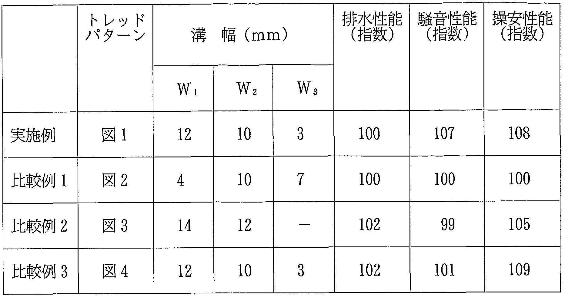
- FIG. 1 is a developed view showing a main part of a tread surface according to an embodiment of the pneumatic tire of the present invention.
- FIG. 1 is a developed view showing a main part of a tread surface of the pneumatic tire of Comparative Example 1.
- FIG. 3 is a developed view showing a main part of a tread surface of the pneumatic tire of Comparative Example 2.
- FIG. 4 is a developed view showing a main part of a tread surface of the pneumatic tire of Comparative Example 3.
- FIG. 1 illustrates an example of a main part of a tread surface of a pneumatic tire according to the present invention.
- the tire has a designated direction of rotation and rotates in the direction of arrow R.
- the center area of the width Tc is the tread center area
- the width of the tread development width TW is 50% of the width of the tread
- both side areas of the width Ts are each the tread shoulder area
- the tread development width is each. It has a width of 25% of TW.
- a straight main groove 1 extending linearly in the circumferential direction is provided in the center of the width Tc tread center area in the width direction, and the right and left sides of the straight main groove 1 are provided on the right and left sides of the tire via ribs 2 and 2, respectively.
- the arc-shaped curved main grooves 3, 3 extending in the direction are provided.
- the arcuate bay curved main groove 3 is formed such that a plurality of arcuate grooves 3a are repeated continuously in the circumferential direction.
- the direction of the convex portion of the arc-shaped groove 3a is on the center side (inside) in FIG. 1, but may be on the opposite side.
- the number of the plurality of arcuate grooves 3a which are continuously present in the circumferential direction is preferably in the range of 20 to 32, more preferably 23 to 29. is there.
- the shape of the “arc-shaped curve” is not so strict, and it is sufficient that the shape of the “arc-shaped curve” is substantially a substantially arc-shaped curve in consideration of the gist of the present invention.
- the arc-shaped curved main groove 3 is see-through in the tire circumferential direction.
- the case 1 means that when the arcuate curved main groove 3 is viewed in the tire circumferential direction, it can be seen through without being obstructed by the left and right groove walls. in this way When the arc-shaped curved raw groove 3 is formed in a single sheath structure, drainage resistance is reduced, which can be advantageous for securing good drainage performance.
- Auxiliary grooves 4, 4 extending linearly in the tire circumferential direction are provided in the tread shoulder region having a width Ts.
- the groove width of the auxiliary groove 4 is formed smaller than the groove width of the straight main groove 1 and the arc-shaped curved main groove 3.
- the left and right auxiliary grooves 4 and 4 are provided with a plurality of inclined grooves 5a and 5b so as to cross diagonally, and the inclined grooves 5a and 5b are alternately arranged at predetermined positions in the tire circumferential direction. They are arranged at intervals.
- the inclined grooves 5a and 5b are gradually inclined in the anti-tire rotation direction from the tread center area toward the tread shoulder.
- One of the inclined grooves 5a passes from the midpoint between the arc-shaped curved main groove 3 and the auxiliary groove 4 to the shoulder end, while the other inclined groove 5b has the trough starting from the arc-shaped curved main groove 3. It extends halfway through the Doshoulder area.
- These inclined grooves 5a and 5b serve to discharge water stepped into the tread center area to the side of the tire through the tread shoulder area, thereby improving drainage performance. Since the pneumatic tire of the present invention is provided with the straight main groove 1 and the pair of left and right arc-shaped curved main grooves 3 and 3 in the region of the tread center as described above, the drainage can be performed efficiently.
- two of the three main grooves are arcuate curved main grooves 3, 3, and these arcuate curved main grooves 3 are formed by connecting a plurality of arcuate grooves 3a in a repeating manner.
- the generation of column resonance can be suppressed, and the air column resonance near 1 kHz is greatly reduced.
- the arc-shaped curved main groove 3 has a larger edge amount than the straight main groove 1, the pet skid property on a road surface having a low friction coefficient is improved.
- the three circumferential main grooves 1, 3, 3 are not provided in the tread shoulder area where a large load is applied during cornering, but are provided in the tread center area, so they are formed in the tread center area. It suppresses the rise in the contact pressure and the change in shear stress of the rebedge and block wedges, thereby improving the tread's contact performance, improving the cornering force, and improving the steering stability.
- the auxiliary groove 4 provided in the tread shoulder region facilitates heat dissipation in the tread shoulder region, and thus alleviates heat sag during continuous running in a circuit, for example.
- the width of the auxiliary groove 4 is smaller than that of the circumferential main grooves 1, 3, and 3, the rigidity of the block formed in the shoulder region is increased, and the cornering force is reduced. Because of the large size, the steering stability can be improved from this point as well.
- the widths of the straight main groove and the arc-shaped curved main groove may be the same or different from each other.
- the width of each groove is preferably in the range of 5 to 15 mm.
- the groove width of the auxiliary groove is smaller than that of the straight main groove or the curved main groove, preferably within 50% of the groove width of the straight main groove or the curved main groove, and 1 to 5 mm. It is preferable to set it in the range.
- the groove width of the inclined groove is preferably in the range of 1 to 7 mm.
- the basic structure of the tread pad in FIG. 2 is similar to that of the tire described in Japanese Patent Application Laid-Open No. 7-164829.
- the vehicle traveled straight on a road surface with a water depth of about 10 mm and the speed at which hydroplaning occurred was measured.
- the evaluation was indicated by an index with the measured value of the tire of Comparative Example 1 being 100. The larger the index value, the better the drainage performance.
- the present invention can be used in the tire manufacturing industry, and eventually in the automobile industry.
Landscapes
- Engineering & Computer Science (AREA)
- Mechanical Engineering (AREA)
- Tires In General (AREA)
Abstract
Description
Claims
Priority Applications (4)
| Application Number | Priority Date | Filing Date | Title |
|---|---|---|---|
| EP03811508A EP1571010B1 (en) | 2002-11-19 | 2003-11-11 | Pneumatic tire |
| US10/531,725 US7614435B2 (en) | 2002-11-19 | 2003-11-11 | Pneumatic tire having circumferential straight main groove, arcuate curved main grooves and circumferential auxiliary grooves |
| CA2501157A CA2501157C (en) | 2002-11-19 | 2003-11-11 | Pneumatic tire |
| DE60335909T DE60335909D1 (de) | 2002-11-19 | 2003-11-11 | Pneumatischer reifen |
Applications Claiming Priority (2)
| Application Number | Priority Date | Filing Date | Title |
|---|---|---|---|
| JP2002335046A JP4017503B2 (ja) | 2002-11-19 | 2002-11-19 | 空気入りタイヤ |
| JP2002-335046 | 2002-11-19 |
Publications (1)
| Publication Number | Publication Date |
|---|---|
| WO2004045871A1 true WO2004045871A1 (ja) | 2004-06-03 |
Family
ID=32321750
Family Applications (1)
| Application Number | Title | Priority Date | Filing Date |
|---|---|---|---|
| PCT/JP2003/014291 WO2004045871A1 (ja) | 2002-11-19 | 2003-11-11 | 空気入りタイヤ |
Country Status (8)
| Country | Link |
|---|---|
| US (1) | US7614435B2 (ja) |
| EP (1) | EP1571010B1 (ja) |
| JP (1) | JP4017503B2 (ja) |
| KR (1) | KR100985007B1 (ja) |
| CN (1) | CN100398344C (ja) |
| CA (1) | CA2501157C (ja) |
| DE (1) | DE60335909D1 (ja) |
| WO (1) | WO2004045871A1 (ja) |
Families Citing this family (17)
| Publication number | Priority date | Publication date | Assignee | Title |
|---|---|---|---|---|
| JP4309119B2 (ja) * | 2002-12-03 | 2009-08-05 | 横浜ゴム株式会社 | 空気入りタイヤ |
| JP4583841B2 (ja) * | 2004-08-31 | 2010-11-17 | 株式会社ブリヂストン | 空気入りタイヤ |
| KR101096990B1 (ko) * | 2006-12-20 | 2011-12-20 | 가부시키가이샤 브리지스톤 | 공기입 타이어 |
| JP4869089B2 (ja) * | 2007-01-22 | 2012-02-01 | 株式会社ブリヂストン | 空気入りタイヤ |
| JP5023845B2 (ja) * | 2007-07-02 | 2012-09-12 | 横浜ゴム株式会社 | 空気入りタイヤ |
| JP4262286B1 (ja) * | 2007-10-23 | 2009-05-13 | 住友ゴム工業株式会社 | 空気入りタイヤ |
| JP4145346B1 (ja) | 2007-11-07 | 2008-09-03 | 横浜ゴム株式会社 | 空気入りタイヤ |
| JP4156018B1 (ja) * | 2007-12-12 | 2008-09-24 | 横浜ゴム株式会社 | 空気入りタイヤ |
| JP4653831B2 (ja) * | 2008-10-28 | 2011-03-16 | 住友ゴム工業株式会社 | 空気入りタイヤ |
| EP2436536B1 (en) * | 2009-05-25 | 2014-09-10 | Bridgestone Corporation | Pneumatic tire |
| WO2011027889A1 (ja) * | 2009-09-07 | 2011-03-10 | 株式会社ブリヂストン | 空気入りタイヤ |
| DE102010061068A1 (de) * | 2010-12-07 | 2012-06-14 | Continental Reifen Deutschland Gmbh | Fahrzeugluftreifen |
| JP5912945B2 (ja) * | 2012-07-10 | 2016-04-27 | 住友ゴム工業株式会社 | 空気入りタイヤ |
| CA155611S (en) * | 2013-09-26 | 2014-11-25 | Continental Reifen Deutschland | Tire |
| DE102015222072B4 (de) * | 2015-11-10 | 2019-03-28 | Robert Bosch Gmbh | Heizvorrichtung für MEMS-Sensor |
| USD848941S1 (en) | 2016-01-28 | 2019-05-21 | Bridgestone Americas Tire Operations, Llc | Tire sidewall |
| USD931790S1 (en) * | 2019-10-30 | 2021-09-28 | Prinx Chengshan (Qingdao) Industrial Research And Design Co., Ltd. | Tire |
Citations (9)
| Publication number | Priority date | Publication date | Assignee | Title |
|---|---|---|---|---|
| JPH06106915A (ja) * | 1992-09-30 | 1994-04-19 | Bridgestone Corp | 空気入りタイヤ |
| JPH0740712A (ja) * | 1993-06-29 | 1995-02-10 | Bridgestone Corp | 空気入りタイヤ |
| EP0648622A1 (en) | 1993-10-19 | 1995-04-19 | Sumitomo Rubber Industries Limited | Pneumatic tyre |
| EP0671287A1 (en) * | 1994-03-08 | 1995-09-13 | Sumitomo Rubber Industries Limited | Pneumatic tyre |
| EP0676305A1 (en) * | 1994-04-11 | 1995-10-11 | Sumitomo Rubber Industries Limited | Pneumatic tyre |
| JP2644499B2 (ja) * | 1987-07-31 | 1997-08-25 | 株式会社ブリヂストン | 高速用空気入りラジアルタイヤ |
| JP2000177325A (ja) | 1998-12-21 | 2000-06-27 | Ohtsu Tire & Rubber Co Ltd :The | 空気入りタイヤ |
| JP3162866B2 (ja) * | 1993-03-16 | 2001-05-08 | 株式会社ブリヂストン | 空気入りタイヤ |
| JP2001206017A (ja) * | 2000-01-26 | 2001-07-31 | Ohtsu Tire & Rubber Co Ltd :The | 空気入りタイヤ |
Family Cites Families (24)
| Publication number | Priority date | Publication date | Assignee | Title |
|---|---|---|---|---|
| US2878852A (en) * | 1955-11-15 | 1959-03-24 | Us Rubber Co | Pneumatic tire having noiseless tread |
| GB1438288A (ja) * | 1972-09-01 | 1976-06-03 | ||
| US4424844A (en) * | 1982-03-17 | 1984-01-10 | The Goodyear Tire & Rubber Company | Tire tread |
| JPS6226104A (ja) * | 1985-07-26 | 1987-02-04 | Yokohama Rubber Co Ltd:The | 乗用車用空気入りラジアルタイヤ |
| JPH0536963Y2 (ja) * | 1987-08-27 | 1993-09-20 | ||
| JPH02204105A (ja) * | 1989-01-31 | 1990-08-14 | Sumitomo Rubber Ind Ltd | 空気入りタイヤ |
| JPH0374208A (ja) * | 1989-08-16 | 1991-03-28 | Yokohama Rubber Co Ltd:The | 乗用車用空気入りタイヤ |
| JP3104029B2 (ja) | 1991-05-22 | 2000-10-30 | 横浜ゴム株式会社 | 空気入りタイヤ |
| DE4239475A1 (de) * | 1992-11-25 | 1994-05-26 | Continental Ag | Fahrzeugreifen mit Laufflächenprofil |
| EP0602989A1 (en) | 1992-12-16 | 1994-06-22 | Sumitomo Rubber Industries, Co. Ltd | Pneumatic tyre |
| DE4302365A1 (de) * | 1993-01-28 | 1994-08-04 | Continental Ag | Fahrzeugreifen mit einer Profilrillen aufweisenden Lauffläche |
| JP3471396B2 (ja) | 1993-12-17 | 2003-12-02 | 横浜ゴム株式会社 | 乗用車用空気入りラジアルタイヤ |
| JP3516742B2 (ja) * | 1994-11-22 | 2004-04-05 | 株式会社ブリヂストン | 空気入りラジアルタイヤ |
| IT1275552B (it) * | 1995-07-14 | 1997-08-07 | Pirelli | Pneumatico polivalente per autoveicoli |
| JP3688791B2 (ja) | 1996-02-19 | 2005-08-31 | 株式会社ブリヂストン | 空気入りラジアルタイヤ |
| JP3636401B2 (ja) | 1996-07-04 | 2005-04-06 | 株式会社ブリヂストン | 空気入りタイヤ |
| DE19708612A1 (de) * | 1997-03-03 | 1998-09-10 | Sp Reifenwerke Gmbh | Fahrzeugreifen |
| JP3771353B2 (ja) | 1997-05-02 | 2006-04-26 | 株式会社ブリヂストン | 空気入りタイヤ |
| JP3774551B2 (ja) | 1997-09-25 | 2006-05-17 | 横浜ゴム株式会社 | 空気入りラジアルタイヤ |
| JP4184469B2 (ja) | 1998-02-18 | 2008-11-19 | 株式会社ブリヂストン | 乗用車用空気入りラジアル・タイヤ |
| DE69930481T2 (de) * | 1998-10-30 | 2006-10-19 | Sumitomo Rubber Industries Ltd., Kobe | Fahrzeugreifen |
| ITMI991447A1 (it) * | 1999-06-30 | 2000-12-30 | Pirelli | Pneumatico ad alte prestazioni per un autoveicolo |
| US6640858B2 (en) | 1999-12-07 | 2003-11-04 | Sumitomo Rubber Industries, Ltd. | Tire having tread grooves having right-hand groove wall and left-hand groove wall |
| JP3441705B2 (ja) * | 2000-08-22 | 2003-09-02 | 住友ゴム工業株式会社 | 空気入りタイヤ |
-
2002
- 2002-11-19 JP JP2002335046A patent/JP4017503B2/ja not_active Expired - Fee Related
-
2003
- 2003-11-11 CA CA2501157A patent/CA2501157C/en not_active Expired - Fee Related
- 2003-11-11 KR KR1020057005904A patent/KR100985007B1/ko active IP Right Grant
- 2003-11-11 CN CNB200380103497XA patent/CN100398344C/zh not_active Expired - Fee Related
- 2003-11-11 EP EP03811508A patent/EP1571010B1/en not_active Expired - Lifetime
- 2003-11-11 US US10/531,725 patent/US7614435B2/en not_active Expired - Lifetime
- 2003-11-11 DE DE60335909T patent/DE60335909D1/de not_active Expired - Lifetime
- 2003-11-11 WO PCT/JP2003/014291 patent/WO2004045871A1/ja active Application Filing
Patent Citations (9)
| Publication number | Priority date | Publication date | Assignee | Title |
|---|---|---|---|---|
| JP2644499B2 (ja) * | 1987-07-31 | 1997-08-25 | 株式会社ブリヂストン | 高速用空気入りラジアルタイヤ |
| JPH06106915A (ja) * | 1992-09-30 | 1994-04-19 | Bridgestone Corp | 空気入りタイヤ |
| JP3162866B2 (ja) * | 1993-03-16 | 2001-05-08 | 株式会社ブリヂストン | 空気入りタイヤ |
| JPH0740712A (ja) * | 1993-06-29 | 1995-02-10 | Bridgestone Corp | 空気入りタイヤ |
| EP0648622A1 (en) | 1993-10-19 | 1995-04-19 | Sumitomo Rubber Industries Limited | Pneumatic tyre |
| EP0671287A1 (en) * | 1994-03-08 | 1995-09-13 | Sumitomo Rubber Industries Limited | Pneumatic tyre |
| EP0676305A1 (en) * | 1994-04-11 | 1995-10-11 | Sumitomo Rubber Industries Limited | Pneumatic tyre |
| JP2000177325A (ja) | 1998-12-21 | 2000-06-27 | Ohtsu Tire & Rubber Co Ltd :The | 空気入りタイヤ |
| JP2001206017A (ja) * | 2000-01-26 | 2001-07-31 | Ohtsu Tire & Rubber Co Ltd :The | 空気入りタイヤ |
Non-Patent Citations (1)
| Title |
|---|
| See also references of EP1571010A4 |
Also Published As
| Publication number | Publication date |
|---|---|
| KR20050070035A (ko) | 2005-07-05 |
| EP1571010A1 (en) | 2005-09-07 |
| CN1711177A (zh) | 2005-12-21 |
| CA2501157C (en) | 2011-03-15 |
| EP1571010A4 (en) | 2010-03-03 |
| KR100985007B1 (ko) | 2010-10-04 |
| US20060162831A1 (en) | 2006-07-27 |
| JP2004168142A (ja) | 2004-06-17 |
| CA2501157A1 (en) | 2004-06-03 |
| US7614435B2 (en) | 2009-11-10 |
| DE60335909D1 (de) | 2011-03-10 |
| CN100398344C (zh) | 2008-07-02 |
| EP1571010B1 (en) | 2011-01-26 |
| JP4017503B2 (ja) | 2007-12-05 |
Similar Documents
| Publication | Publication Date | Title |
|---|---|---|
| WO2004045871A1 (ja) | 空気入りタイヤ | |
| JP5181927B2 (ja) | 空気入りタイヤ | |
| EP1498288A1 (en) | Pneumatic tire | |
| JP3519473B2 (ja) | 氷雪上走行用空気入りタイヤ | |
| WO2006001202A1 (ja) | 空気入りタイヤ | |
| JP2010285035A (ja) | 空気入りタイヤ | |
| WO2008075630A1 (ja) | 空気入りタイヤ | |
| JP3383405B2 (ja) | ストレート溝を有する空気入りタイヤ | |
| JP2001187520A (ja) | 空気入りタイヤ | |
| JP4184469B2 (ja) | 乗用車用空気入りラジアル・タイヤ | |
| JP4441009B2 (ja) | 空気入りタイヤ | |
| JP2002283812A (ja) | スタッドレスタイヤ | |
| JP2000255217A (ja) | 空気入りタイヤ | |
| JP4145397B2 (ja) | 二輪自動車用空気入りタイヤ | |
| JP2749879B2 (ja) | 非対称トレッドを備えた空気入りタイヤ | |
| JP4281863B2 (ja) | 空気入りタイヤ | |
| JP2009001156A (ja) | 空気入りタイヤ | |
| JP3860308B2 (ja) | オール・シーズン乗用車用空気入りラジアル・タイヤ | |
| JP4758059B2 (ja) | 空気入りタイヤ | |
| JPH0825917A (ja) | 方向性傾斜溝を有する氷雪上走行用空気入りタイヤ | |
| JP2010221967A (ja) | タイヤ | |
| JP4345886B2 (ja) | 回転方向を指定されたブロックパターンを有する空気入りタイヤ | |
| JPH08164714A (ja) | 空気入りラジアルタイヤ | |
| JP4359037B2 (ja) | 空気入りタイヤ | |
| JP2000238511A (ja) | 排水性能に優れた乗用車用空気入りタイヤ |
Legal Events
| Date | Code | Title | Description |
|---|---|---|---|
| AK | Designated states |
Kind code of ref document: A1 Designated state(s): CA CN KR US |
|
| AL | Designated countries for regional patents |
Kind code of ref document: A1 Designated state(s): DE FR GB IT |
|
| 121 | Ep: the epo has been informed by wipo that ep was designated in this application | ||
| WWE | Wipo information: entry into national phase |
Ref document number: 2501157 Country of ref document: CA |
|
| WWE | Wipo information: entry into national phase |
Ref document number: 1020057005904 Country of ref document: KR |
|
| ENP | Entry into the national phase |
Ref document number: 2006162831 Country of ref document: US Kind code of ref document: A1 |
|
| WWE | Wipo information: entry into national phase |
Ref document number: 10531725 Country of ref document: US |
|
| WWE | Wipo information: entry into national phase |
Ref document number: 20038A3497X Country of ref document: CN |
|
| WWE | Wipo information: entry into national phase |
Ref document number: 2003811508 Country of ref document: EP |
|
| WWP | Wipo information: published in national office |
Ref document number: 1020057005904 Country of ref document: KR |
|
| WWP | Wipo information: published in national office |
Ref document number: 2003811508 Country of ref document: EP |
|
| WWP | Wipo information: published in national office |
Ref document number: 10531725 Country of ref document: US |