EP1571010B1 - Pneumatic tire - Google Patents
Pneumatic tire Download PDFInfo
- Publication number
- EP1571010B1 EP1571010B1 EP03811508A EP03811508A EP1571010B1 EP 1571010 B1 EP1571010 B1 EP 1571010B1 EP 03811508 A EP03811508 A EP 03811508A EP 03811508 A EP03811508 A EP 03811508A EP 1571010 B1 EP1571010 B1 EP 1571010B1
- Authority
- EP
- European Patent Office
- Prior art keywords
- grooves
- pneumatic tire
- tread
- groove
- arc
- Prior art date
- Legal status (The legal status is an assumption and is not a legal conclusion. Google has not performed a legal analysis and makes no representation as to the accuracy of the status listed.)
- Expired - Lifetime
Links
Images
Classifications
-
- B—PERFORMING OPERATIONS; TRANSPORTING
- B60—VEHICLES IN GENERAL
- B60C—VEHICLE TYRES; TYRE INFLATION; TYRE CHANGING; CONNECTING VALVES TO INFLATABLE ELASTIC BODIES IN GENERAL; DEVICES OR ARRANGEMENTS RELATED TO TYRES
- B60C11/00—Tyre tread bands; Tread patterns; Anti-skid inserts
- B60C11/03—Tread patterns
- B60C11/0306—Patterns comprising block rows or discontinuous ribs
-
- B—PERFORMING OPERATIONS; TRANSPORTING
- B60—VEHICLES IN GENERAL
- B60C—VEHICLE TYRES; TYRE INFLATION; TYRE CHANGING; CONNECTING VALVES TO INFLATABLE ELASTIC BODIES IN GENERAL; DEVICES OR ARRANGEMENTS RELATED TO TYRES
- B60C11/00—Tyre tread bands; Tread patterns; Anti-skid inserts
- B60C11/01—Shape of the shoulders between tread and sidewall, e.g. rounded, stepped or cantilevered
-
- B—PERFORMING OPERATIONS; TRANSPORTING
- B60—VEHICLES IN GENERAL
- B60C—VEHICLE TYRES; TYRE INFLATION; TYRE CHANGING; CONNECTING VALVES TO INFLATABLE ELASTIC BODIES IN GENERAL; DEVICES OR ARRANGEMENTS RELATED TO TYRES
- B60C11/00—Tyre tread bands; Tread patterns; Anti-skid inserts
- B60C11/03—Tread patterns
- B60C11/0302—Tread patterns directional pattern, i.e. with main rolling direction
Definitions
- the present invention relates to a pneumatic tire.
- Embodiments of the pneumatic tire can improve noise buffering capability and operation stability while maintaining water discharge capability.
- a pneumatic tire having a tread pattern where a plurality of straight main grooves are circumferentially provided on a tread surface is known as disclosed in Japanese Patent Application Kokai publication No. Hei 7 (1995) -164829 and the like, for example.
- the pneumatic tire having a tread pattern as described above is excellent in water discharge capability, on the contrary, the pneumatic tire has suffered from a disadvantage that cavity noise is large.
- the tread pattern where main grooves having a V-shape are provided does not necessarily have sufficient water discharge capability at a time when a vehicle travels in a straight direction for their widths.
- a footprint width will decrease, thereby leading to the reduction of cornering force which causes the operation stability to decrease.
- the capability level of the pneumatic tire in which main grooves having a V-shape are provided as described above does not always exceed the capability level of the pneumatic tire based on circumferential straight main grooves as described in the aforementioned Japanese Patent Application Kokai publication No. Hei 7 (1995) -164829 .
- a pneumatic tire wherein a circumferential straight main groove is provided at the center of a tread center region; arcuate curved main grooves where each of a plurality of arcuate grooves is circumferentially formed so as to be continuous in a repeated manner are arranged on both sides of the straight main groove; and further, each of circumferential auxiliary grooves with a width smaller than that of any of the straight main groove and arcuate curved main grooves is provided in both tread shoulder regions respectively, characterized in that the arcuate curved main grooves are circumferentially formed to be in a see-through state.
- the arc-like curved main grooves have a total length of edges longer than that of the straight main grooves, wet skid performance on a road having a low friction coefficient can be improved.
- auxiliary grooves are provided in the tread shoulder region which is subjected to large load in cornering, heat radiation capability are improved and heat sag which may occur in continuous running in a circuit or the like can be buffered.
- each of the auxiliary grooves has a width smaller than that of any of the three circumferential main grooves, the block rigidity in this tread shoulder region is increased and the operation stability can be improved also in this point.
- heat sag means a phenomenon that rubber is softened due to the heat generation in running and the driving performance reduces.
- Embodiments of the present invention can improve noise buffering capability and operation stability while maintaining excellent water discharge capability.
- embodiments of the present invention can provide a new pneumatic tire in order to solve the aforementioned problems in the prior art, and to improve noise buffering capability and operation stability while maintaining water discharge capability at a high level.
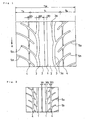
- Fig. 1 illustrates a principal part of a tread surface of a pneumatic tire which is an embodiment of the present invention.
- a tire rotates in a given direction, specifically in a direction indicated by the arrow R.
- a center region with a width Tc is assigned as a tread center region, and the tread center region has a width of 50 % of a tread expanded length TW.
- Respective regions on both sides of the tread center region with a width Ts are assigned as tread shoulder regions, and each of the tread center regions has a width of 25 % of the tread expanded length TW.
- a straight main groove 1 which extends circumferentially on a tread surface and is located at the center of the tread width.
- arc-like curved main grooves 3 and 3 extending in a tire circumferential direction are provided respectively with ribs 2 and 2 interposed therebetween.
- the arc-like curved main grooves 3 are formed so that a plurality of arc-like grooves 3a are circumferentially formed so as to be continuous in a repeatedmanner.
- the orientation of a convex portion of each arc-like groove 3a points to a center side (inside) in Fig. 1 , but the orientation thereof may point to an outside instead of inside.
- the number of the plural arc-like grooves 3a which exist circumferentially so as to be continuous in a repeated manner is preferably set at a range of 20 to 32, more preferably at a range of 23 to 29.
- "Arc-like curve” is not so strictly limited in shape, and may be one which can be considered as "arc-like curve” substantially as a whole in light of the present disclosure.
- the arc-like curved main grooves 3 are preferably configured to be in a see-through state in the tire circumferential direction.
- "See-through” means that when the arc-like curved main grooves 3 are seen in the tire circumferential direction, the arc-like curved main grooves 3 can be seen without obstruction to view caused by left and right groove walls.
- the arc-like curvedmain grooves 3 are configured to be in a see-through state as described above, drainage resistance is reduced and an advantageous situation for maintaining excellent water discharge capability can be increased.
- auxiliary grooves 4 and 4 extending in a line in the tire circumferential direction are provided respectively.
- the width of the auxiliary groove 4 is formed to be smaller than that of straight main groove 1 and arc-like curved main groove 3.
- a plurality of inclined grooves 5a and 5b are provided so as to cross the auxiliary grooves diagonally.
- the inclined grooves 5a and 5b are provided with a given interval therebetween in a tire circumferential direction so as to be alternate with each other.
- the inclined grooves 5a and 5b gradually incline from the tread center region to the tread shoulder region in a direction reverse to a tire rotation direction. Additionally, the inclined groove 5a extends from an intermediate point between the arc-like curved main groove 3 and the auxiliary groove 4 to the edge of the tread shoulder region, and on the other hand, the inclined groove 5b extends from the arc-like curved main groove 3 as a starting point to the middle of the tread shoulder region.
- These inclined grooves 5a and 5b work to discharge water entered into the tread center region to the side of the tire through the tread shoulder, thereby improving water discharge capability.
- the straight main groove 1 and the pair of left and right arc-like curved main grooves 3 and 3 are provided in the tread center region as described above, water discharge can be performed efficiently. Furthermore, two of the three main grooves are arc-like curved main grooves 3 and 3, where the plurality of arc-like grooves 3a are formed so as to be continuous in a repeated manner and connected to each other, and thereby the occurrence of cavity noise can be suppressed and in particular cavity noise around 1 kHz can be reduced to a large extent. Moreover, since the arc-like curved main grooves 3 have a total length of edges longer than that of the straight main grooves 1, wet skid performance on a road having a low friction coefficient can be improved.
- the three circumferential main grooves 1, 3, and 3 are provided in the tread center region instead of the tread shoulder region where large load is applied in cornering, the rise in contact pressure and the change in shear stress, which may occur in the rib edge or block edge formed in the tread center region, can be suppressed, whereby road holding ability of the tread can be improved. As a result, the cornering force is increased and operation stability is improved.
- auxiliary grooves 4 provided in the tread shoulder region promote heat radiation capability in the tread shoulder region, heat sag which may occur, for example, in continuous running in a circuit or the like is buffered. Additionally, since each of the auxiliary grooves 4 has a width smaller than that of any of the circumferential main grooves 1, 3, and 3, the rigidity of the block formed in the tread shoulder region is increased and the cornering force is increased. Also in this point, the operation stability can be improved.
- the widths of the straight main groove and the arc-like curved main groove may be the same or different from each other.
- Each of the widths is preferably set at a range of 5 to 15 mm respectively.
- the width of the auxiliary groove is smaller than that of the straight main groove and the arc-like main groove, and preferably set to 50% or below of the width of the straight main groove and the arc-like curved main groove.
- the width of the auxiliary groove is preferably set at a range of 1 to 5 mm.
- the width of the inclined groove is preferably set at a range of 1 to 7 mm.
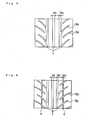
- tread pattern of Fig. 2 is one whose basic configuration is made to be similar to a tire disclosed in Japanese Patent Application Kokai publication No. Hei 7 (1995) -164829 .
- the speed when running straight on a wet road with a water depth of about 10 mm and hydroplaning was occurred was measured. Evaluation is indicated by an index with the measured value of the tire according to Comparative Example 1 being defined as 100. A larger index represents more excellent water discharge capability.
- the present invention can be applied to tire industry, and consequently to automobile industry.
Landscapes
- Engineering & Computer Science (AREA)
- Mechanical Engineering (AREA)
- Tires In General (AREA)
Abstract
Description
- The present invention relates to a pneumatic tire. Embodiments of the pneumatic tire can improve noise buffering capability and operation stability while maintaining water discharge capability.
- A pneumatic tire having a tread pattern where a plurality of straight main grooves are circumferentially provided on a tread surface is known as disclosed in Japanese Patent Application Kokai publication No.
Hei 7 (1995) -164829 - However, although the pneumatic tire having a tread pattern as described above is excellent in water discharge capability, on the contrary, the pneumatic tire has suffered from a disadvantage that cavity noise is large.
- In order to reduce a disadvantage of having cavity noise caused by the straight main grooves provided circumferentially as described above while maintaining an advantage of having excellent water discharge capability caused by the straight main grooves as much as possible, a plurality of tread patterns where main grooves having a V-shape are provided have been proposed.
- However, the tread pattern where main grooves having a V-shape are provided does not necessarily have sufficient water discharge capability at a time when a vehicle travels in a straight direction for their widths. To overcome this problem, however, if the width is broadened in order to improve the water discharge capability, a footprint width will decrease, thereby leading to the reduction of cornering force which causes the operation stability to decrease.
- Therefore, the capability level of the pneumatic tire in which main grooves having a V-shape are provided as described above does not always exceed the capability level of the pneumatic tire based on circumferential straight main grooves as described in the aforementioned Japanese Patent Application Kokai publication No.
Hei 7 (1995) -164829 - Prior art pneumatic tires are also known from
JP 2000 177325 A EP-A-0 648 622 . These documents fail to disclose the characterizing features of the present invention as defined inClaim 1. - According to the present invention, there is provided a pneumatic tire, wherein a circumferential straight main groove is provided at the center of a tread center region; arcuate curved main grooves where each of a plurality of arcuate grooves is circumferentially formed so as to be continuous in a repeated manner are arranged on both sides of the straight main groove; and further, each of circumferential auxiliary grooves with a width smaller than that of any of the straight main groove and arcuate curved main grooves is provided in both tread shoulder regions respectively, characterized in that the arcuate curved main grooves are circumferentially formed to be in a see-through state.
- By providing the straight main groove and the pair of left and right arc-like curved main grooves in a tread center region as described above, efficient water discharge can be performed by use of these three main grooves. Furthermore, since two of the three main grooves are made to be arc-like curved main grooves, where a plurality of arc-like grooves are circumferentially formed so as to be continuous in a repeated manner, cavity noise does not easily occur and cavity noise around 1 kHz can be reduced to a large extent.
- Moreover, since the arc-like curved main grooves have a total length of edges longer than that of the straight main grooves, wet skid performance on a road having a low friction coefficient can be improved.
- In addition, by providing three circumferential main grooves in the tread center region while separating them from the tread shoulder region which is subjected to large load in cornering, the rise in contact pressure and the change in shear stress which may occur in a main groove wall (rib edge/block edge) can be suppressed, and road holding ability can be improved. As a result, the cornering force is increased and operation stability is improved.
- Moreover, since auxiliary grooves are provided in the tread shoulder region which is subjected to large load in cornering, heat radiation capability are improved and heat sag which may occur in continuous running in a circuit or the like can be buffered. Additionally, since each of the auxiliary grooves has a width smaller than that of any of the three circumferential main grooves, the block rigidity in this tread shoulder region is increased and the operation stability can be improved also in this point. Here, the aforementioned "heat sag" means a phenomenon that rubber is softened due to the heat generation in running and the driving performance reduces.
- Embodiments of the present invention, as described above, can improve noise buffering capability and operation stability while maintaining excellent water discharge capability.
- Further, embodiments of the present invention can provide a new pneumatic tire in order to solve the aforementioned problems in the prior art, and to improve noise buffering capability and operation stability while maintaining water discharge capability at a high level.
- To enable a better understanding of the present invention, and to show how the same may be carried into effect, reference will now be made, by way of example only, to the accompanying drawings, in which:-
-
Fig. 1 is an expanded view showing a principal part of a tread surface of a pneumatic tire which is an embodiment of the present invention; -
Fig. 2 is an expanded view showing a principal part of a tread surface of a pneumatic tire according to Comparative Example 1; -
Fig. 3 is an expanded view showing a principal part of a tread surface of a pneumatic tire according to Comparative Example 2; and -
Fig. 4 is an expanded view showing a principal part of a tread surface of a pneumatic tire according to Comparative Example 3. - Hereinafter, an embodiment of the present invention will be described with reference to
Fig. 1 . -
Fig. 1 illustrates a principal part of a tread surface of a pneumatic tire which is an embodiment of the present invention. A tire rotates in a given direction, specifically in a direction indicated by the arrow R. Additionally, a center region with a width Tc is assigned as a tread center region, and the tread center region has a width of 50 % of a tread expanded length TW. Respective regions on both sides of the tread center region with a width Ts are assigned as tread shoulder regions, and each of the tread center regions has a width of 25 % of the tread expanded length TW. - In the tread center region with a width Tc, there is provided a straight
main groove 1 which extends circumferentially on a tread surface and is located at the center of the tread width. On both right and left sides of this straightmain groove 1, arc-like curvedmain grooves ribs main grooves 3 are formed so that a plurality of arc-like grooves 3a are circumferentially formed so as to be continuous in a repeatedmanner. The orientation of a convex portion of each arc-like groove 3a points to a center side (inside) inFig. 1 , but the orientation thereof may point to an outside instead of inside. - The number of the plural arc-
like grooves 3a which exist circumferentially so as to be continuous in a repeated manner is preferably set at a range of 20 to 32, more preferably at a range of 23 to 29. "Arc-like curve" is not so strictly limited in shape, and may be one which can be considered as "arc-like curve" substantially as a whole in light of the present disclosure. - However, the arc-like curved
main grooves 3 are preferably configured to be in a see-through state in the tire circumferential direction. "See-through" means that when the arc-like curvedmain grooves 3 are seen in the tire circumferential direction, the arc-like curvedmain grooves 3 can be seen without obstruction to view caused by left and right groove walls. When the arc-like curvedmain grooves 3 are configured to be in a see-through state as described above, drainage resistance is reduced and an advantageous situation for maintaining excellent water discharge capability can be increased. - In each of the tread shoulder regions with a width Ts,
auxiliary grooves auxiliary groove 4 is formed to be smaller than that of straightmain groove 1 and arc-like curvedmain groove 3. In addition, in the left and rightauxiliary grooves inclined grooves inclined grooves - The
inclined grooves inclined groove 5a extends from an intermediate point between the arc-like curvedmain groove 3 and theauxiliary groove 4 to the edge of the tread shoulder region, and on the other hand, theinclined groove 5b extends from the arc-like curvedmain groove 3 as a starting point to the middle of the tread shoulder region. Theseinclined grooves - In the pneumatic tire described herein, since the straight
main groove 1 and the pair of left and right arc-like curvedmain grooves main grooves like grooves 3a are formed so as to be continuous in a repeated manner and connected to each other, and thereby the occurrence of cavity noise can be suppressed and in particular cavity noise around 1 kHz can be reduced to a large extent. Moreover, since the arc-like curvedmain grooves 3 have a total length of edges longer than that of the straightmain grooves 1, wet skid performance on a road having a low friction coefficient can be improved. - Furthermore, since the three circumferential
main grooves - Moreover, since the
auxiliary grooves 4 provided in the tread shoulder region promote heat radiation capability in the tread shoulder region, heat sag which may occur, for example, in continuous running in a circuit or the like is buffered. Additionally, since each of theauxiliary grooves 4 has a width smaller than that of any of the circumferentialmain grooves - In the pneumatic tire described herein, the widths of the straight main groove and the arc-like curved main groove may be the same or different from each other. Each of the widths is preferably set at a range of 5 to 15 mm respectively. Moreover, the width of the auxiliary groove is smaller than that of the straight main groove and the arc-like main groove, and preferably set to 50% or below of the width of the straight main groove and the arc-like curved main groove. Additionally, the width of the auxiliary groove is preferably set at a range of 1 to 5 mm. The width of the inclined groove is preferably set at a range of 1 to 7 mm. By selecting the size of the widths as described above, the aforementioned effect can be further improved.
- Four kinds of pneumatic radial tires according to the above described embodiment and Comparative Examples 1 to 3 were manufactured. The tire size of respective tires is the same, specifically 235/45R17. The tread patterns thereof are different from each other as shown in
Figs. 1 to 4 . The widths of main grooves and auxiliary groove W1, W2, and W3 are different from each other as shown in table 1. (Additionally, with respect to the total sum of the width of the grooves, all the tires are the same.) - Note that the tread pattern of
Fig. 2 is one whose basic configuration is made to be similar to a tire disclosed in Japanese Patent Application Kokai publication No.Hei 7 (1995) -164829 - These four kind of tires were respectively fitted to rear wheel/front wheel of a domestically produced car of 2000 cc displacement, on which an engine with a turbocharger was mounted, with air pressure set to 220/190 kPa (rear wheel/front wheel). Then water discharge capability, noise buffering capability, and operation stability were measured by use of the measurement method described below. Results are shown in Table 1.
- The speed when running straight on a wet road with a water depth of about 10 mm and hydroplaning was occurred was measured. Evaluation is indicated by an index with the measured value of the tire according to Comparative Example 1 being defined as 100. A larger index represents more excellent water discharge capability.
- In conformity with ISO STANDARD: WD 13325-EU, pass-by noise was measured. Evaluation was performed by use of inverse numbers of the measured values and indicated by an index with inverse numbers of the measured value of the tire according to Comparative Example 1 being defined as 100. A larger index represents more excellent noise buffering capability.
- Sensory road tests by five test drivers in a circuit were preformed, and the average value of evaluation scores by the five test drivers was used for the evaluation. The evaluation is indicated by an index with evaluation value of the tire according to Comparative Example 1 being defined as 100. A larger index represents more excellent operation stability.
Table 1 Tread pattern Width (mm) Water discharge capability (index) Noise buffering capability (index) Operation stability (index) W1 W2 W3 Example Fig. 1 12 10 3 100 107 108 Comparative Example 1 Fig. 2 4 10 7 100 100 100 Comparative Example 2 Fig. 3 14 12 - 102 99 105 Comparative Example 3 Fig. 4 12 10 3 102 101 109 - The present invention can be applied to tire industry, and consequently to automobile industry.
Claims (6)
- A pneumatic tire, wherein
a circumferential straight main groove (1) is provided at the center of a tread center region; arcuate curved main grooves (3) where each of a plurality of arcuate grooves (3a) is circumferentially formed so as to be continuous in a repeated manner are arranged on both sides of the straight main groove (1); and further, each of circumferential auxiliary grooves (4) with a width smaller than that of any of the straight main groove (1) and arcuate curved main grooves (3) is provided in both tread shoulder regions respectively, characterized in that
the arcuate curved main grooves (3) are circumferentially formed to be in a see-through state. - The pneumatic tire according to any of claim 1, wherein, a plurality of inclined grooves (5a, 5b) are provided circumferentially with a given interval therebetween so as to cross the auxiliary grooves (4) diagonally.
- The pneumatic tire according to claim 2, wherein an inner edge portion of the inclined groove (5a, 5b) is connected to the arcuate curved main groove (3).
- The pneumatic tire according to any of claims 1 to 3, wherein each of the widths of the straight main groove (1) and the arcuate curved main groove (3) is 5 to 15 mm.
- The pneumatic tire according to any of claims 1 to 4, wherein the width of the auxiliary groove (4) is 1 to 5 mm.
- The pneumatic tire according to any of claims 2 to 5, wherein the width of the inclined groove (5a, 5b) is 1 to 7 mm.
Applications Claiming Priority (3)
| Application Number | Priority Date | Filing Date | Title |
|---|---|---|---|
| JP2002335046A JP4017503B2 (en) | 2002-11-19 | 2002-11-19 | Pneumatic tire |
| JP2002335046 | 2002-11-19 | ||
| PCT/JP2003/014291 WO2004045871A1 (en) | 2002-11-19 | 2003-11-11 | Pneumatic tire |
Publications (3)
| Publication Number | Publication Date |
|---|---|
| EP1571010A1 EP1571010A1 (en) | 2005-09-07 |
| EP1571010A4 EP1571010A4 (en) | 2010-03-03 |
| EP1571010B1 true EP1571010B1 (en) | 2011-01-26 |
Family
ID=32321750
Family Applications (1)
| Application Number | Title | Priority Date | Filing Date |
|---|---|---|---|
| EP03811508A Expired - Lifetime EP1571010B1 (en) | 2002-11-19 | 2003-11-11 | Pneumatic tire |
Country Status (8)
| Country | Link |
|---|---|
| US (1) | US7614435B2 (en) |
| EP (1) | EP1571010B1 (en) |
| JP (1) | JP4017503B2 (en) |
| KR (1) | KR100985007B1 (en) |
| CN (1) | CN100398344C (en) |
| CA (1) | CA2501157C (en) |
| DE (1) | DE60335909D1 (en) |
| WO (1) | WO2004045871A1 (en) |
Families Citing this family (17)
| Publication number | Priority date | Publication date | Assignee | Title |
|---|---|---|---|---|
| JP4309119B2 (en) * | 2002-12-03 | 2009-08-05 | 横浜ゴム株式会社 | Pneumatic tire |
| JP4583841B2 (en) * | 2004-08-31 | 2010-11-17 | 株式会社ブリヂストン | Pneumatic tire |
| EP2123486B1 (en) * | 2006-12-20 | 2016-07-20 | Bridgestone Corporation | Pneumatic tire |
| JP4869089B2 (en) * | 2007-01-22 | 2012-02-01 | 株式会社ブリヂストン | Pneumatic tire |
| JP5023845B2 (en) * | 2007-07-02 | 2012-09-12 | 横浜ゴム株式会社 | Pneumatic tire |
| JP4262286B1 (en) | 2007-10-23 | 2009-05-13 | 住友ゴム工業株式会社 | Pneumatic tire |
| JP4145346B1 (en) | 2007-11-07 | 2008-09-03 | 横浜ゴム株式会社 | Pneumatic tire |
| JP4156018B1 (en) * | 2007-12-12 | 2008-09-24 | 横浜ゴム株式会社 | Pneumatic tire |
| JP4653831B2 (en) * | 2008-10-28 | 2011-03-16 | 住友ゴム工業株式会社 | Pneumatic tire |
| CN102458884B (en) * | 2009-05-25 | 2014-11-26 | 株式会社普利司通 | Pneumatic tire |
| WO2011027889A1 (en) * | 2009-09-07 | 2011-03-10 | 株式会社ブリヂストン | Pneumatic tire |
| DE102010061068A1 (en) * | 2010-12-07 | 2012-06-14 | Continental Reifen Deutschland Gmbh | Vehicle tires |
| JP5912945B2 (en) * | 2012-07-10 | 2016-04-27 | 住友ゴム工業株式会社 | Pneumatic tire |
| CA155611S (en) * | 2013-09-26 | 2014-11-25 | Continental Reifen Deutschland | Tire |
| DE102015222072B4 (en) * | 2015-11-10 | 2019-03-28 | Robert Bosch Gmbh | Heating device for MEMS sensor |
| USD848941S1 (en) | 2016-01-28 | 2019-05-21 | Bridgestone Americas Tire Operations, Llc | Tire sidewall |
| USD931790S1 (en) * | 2019-10-30 | 2021-09-28 | Prinx Chengshan (Qingdao) Industrial Research And Design Co., Ltd. | Tire |
Family Cites Families (33)
| Publication number | Priority date | Publication date | Assignee | Title |
|---|---|---|---|---|
| US2878852A (en) * | 1955-11-15 | 1959-03-24 | Us Rubber Co | Pneumatic tire having noiseless tread |
| GB1438288A (en) * | 1972-09-01 | 1976-06-03 | ||
| US4424844A (en) | 1982-03-17 | 1984-01-10 | The Goodyear Tire & Rubber Company | Tire tread |
| JPS6226104A (en) * | 1985-07-26 | 1987-02-04 | Yokohama Rubber Co Ltd:The | Pneumatic radial tire for passenger car |
| JP2644499B2 (en) * | 1987-07-31 | 1997-08-25 | 株式会社ブリヂストン | Pneumatic radial tire for high speed |
| JPH0536963Y2 (en) * | 1987-08-27 | 1993-09-20 | ||
| JPH02204105A (en) * | 1989-01-31 | 1990-08-14 | Sumitomo Rubber Ind Ltd | Pneumatic tire |
| JPH0374208A (en) * | 1989-08-16 | 1991-03-28 | Yokohama Rubber Co Ltd:The | Pneumatic tire for automobile |
| JP3104029B2 (en) | 1991-05-22 | 2000-10-30 | 横浜ゴム株式会社 | Pneumatic tire |
| JPH06106915A (en) * | 1992-09-30 | 1994-04-19 | Bridgestone Corp | Pneumatic tire |
| DE4239475A1 (en) * | 1992-11-25 | 1994-05-26 | Continental Ag | Tyre tread with minimal aquaplaning - has sets of longer and shorter arc-shaped grooves running at acute angle from and back to edge, meeting edges at different points |
| EP0602989A1 (en) | 1992-12-16 | 1994-06-22 | Sumitomo Rubber Industries, Co. Ltd | Pneumatic tyre |
| DE4302365A1 (en) * | 1993-01-28 | 1994-08-04 | Continental Ag | Tyre tread with reduced stresses in base of transverse grooves |
| JP3162866B2 (en) * | 1993-03-16 | 2001-05-08 | 株式会社ブリヂストン | Pneumatic tire |
| JPH0740712A (en) * | 1993-06-29 | 1995-02-10 | Bridgestone Corp | Pneumatic tire |
| JP3395986B2 (en) | 1993-10-19 | 2003-04-14 | 住友ゴム工業株式会社 | Pneumatic tire |
| JP3471396B2 (en) | 1993-12-17 | 2003-12-02 | 横浜ゴム株式会社 | Pneumatic radial tires for passenger cars |
| JP2966748B2 (en) | 1994-03-08 | 1999-10-25 | 住友ゴム工業株式会社 | Pneumatic tire |
| DE69503547T2 (en) | 1994-04-11 | 1998-11-19 | Sumitomo Rubber Ind | tire |
| JP3516742B2 (en) * | 1994-11-22 | 2004-04-05 | 株式会社ブリヂストン | Pneumatic radial tire |
| IT1275552B (en) * | 1995-07-14 | 1997-08-07 | Pirelli | MULTI-PURPOSE TIRE FOR MOTOR VEHICLES |
| JP3688791B2 (en) | 1996-02-19 | 2005-08-31 | 株式会社ブリヂストン | Pneumatic radial tire |
| JP3636401B2 (en) | 1996-07-04 | 2005-04-06 | 株式会社ブリヂストン | Pneumatic tire |
| DE19708612A1 (en) * | 1997-03-03 | 1998-09-10 | Sp Reifenwerke Gmbh | Vehicle tires |
| JP3771353B2 (en) | 1997-05-02 | 2006-04-26 | 株式会社ブリヂストン | Pneumatic tire |
| JP3774551B2 (en) | 1997-09-25 | 2006-05-17 | 横浜ゴム株式会社 | Pneumatic radial tire |
| JP4184469B2 (en) | 1998-02-18 | 2008-11-19 | 株式会社ブリヂストン | Pneumatic radial tires for passenger cars |
| DE69930481T2 (en) * | 1998-10-30 | 2006-10-19 | Sumitomo Rubber Industries Ltd., Kobe | vehicle tires |
| JP4302218B2 (en) | 1998-12-21 | 2009-07-22 | 住友ゴム工業株式会社 | Pneumatic tire |
| ITMI991447A1 (en) * | 1999-06-30 | 2000-12-30 | Pirelli | HIGH PERFORMANCE TIRE FOR A VEHICLE |
| US6640858B2 (en) | 1999-12-07 | 2003-11-04 | Sumitomo Rubber Industries, Ltd. | Tire having tread grooves having right-hand groove wall and left-hand groove wall |
| JP4397494B2 (en) * | 2000-01-26 | 2010-01-13 | 住友ゴム工業株式会社 | Pneumatic tire |
| JP3441705B2 (en) * | 2000-08-22 | 2003-09-02 | 住友ゴム工業株式会社 | Pneumatic tire |
-
2002
- 2002-11-19 JP JP2002335046A patent/JP4017503B2/en not_active Expired - Fee Related
-
2003
- 2003-11-11 KR KR1020057005904A patent/KR100985007B1/en not_active Expired - Fee Related
- 2003-11-11 CA CA2501157A patent/CA2501157C/en not_active Expired - Fee Related
- 2003-11-11 US US10/531,725 patent/US7614435B2/en not_active Expired - Lifetime
- 2003-11-11 WO PCT/JP2003/014291 patent/WO2004045871A1/en not_active Ceased
- 2003-11-11 DE DE60335909T patent/DE60335909D1/en not_active Expired - Lifetime
- 2003-11-11 EP EP03811508A patent/EP1571010B1/en not_active Expired - Lifetime
- 2003-11-11 CN CNB200380103497XA patent/CN100398344C/en not_active Expired - Fee Related
Also Published As
| Publication number | Publication date |
|---|---|
| EP1571010A4 (en) | 2010-03-03 |
| CA2501157A1 (en) | 2004-06-03 |
| DE60335909D1 (en) | 2011-03-10 |
| US20060162831A1 (en) | 2006-07-27 |
| US7614435B2 (en) | 2009-11-10 |
| WO2004045871A1 (en) | 2004-06-03 |
| CA2501157C (en) | 2011-03-15 |
| CN1711177A (en) | 2005-12-21 |
| KR20050070035A (en) | 2005-07-05 |
| JP4017503B2 (en) | 2007-12-05 |
| EP1571010A1 (en) | 2005-09-07 |
| JP2004168142A (en) | 2004-06-17 |
| CN100398344C (en) | 2008-07-02 |
| KR100985007B1 (en) | 2010-10-04 |
Similar Documents
| Publication | Publication Date | Title |
|---|---|---|
| EP3178668B1 (en) | Pneumatic tire | |
| EP1571010B1 (en) | Pneumatic tire | |
| EP3213931B1 (en) | Pneumatic tire | |
| CN105882321B (en) | Pneumatic tire | |
| EP2591923B1 (en) | Pneumatic tire | |
| EP3093162B1 (en) | Pneumatic tire | |
| EP1645441B1 (en) | Pneumatic tire | |
| CN1319763C (en) | Pneumatic tire | |
| EP1695843B1 (en) | Pneumatic tire | |
| CN110422015B (en) | Tyre for vehicle wheels | |
| EP2692543B1 (en) | Pneumatic tire | |
| EP3466726B1 (en) | Tire | |
| EP3456552B1 (en) | Tire | |
| EP1676725B1 (en) | Pneumatic tire | |
| EP3822093B1 (en) | Tire | |
| EP3885163B1 (en) | Tire | |
| EP3552847A1 (en) | Tire | |
| JP7275782B2 (en) | tire | |
| JP2022166705A (en) | tire | |
| EP4163128B1 (en) | Tire for rough terrain | |
| EP3838626B1 (en) | Tire | |
| CN110588249A (en) | Tyre for vehicle wheels | |
| EP3718787B1 (en) | Tire | |
| EP3936351B1 (en) | Pneumatic tire | |
| US20250135807A1 (en) | Tire |
Legal Events
| Date | Code | Title | Description |
|---|---|---|---|
| PUAI | Public reference made under article 153(3) epc to a published international application that has entered the european phase |
Free format text: ORIGINAL CODE: 0009012 |
|
| 17P | Request for examination filed |
Effective date: 20050519 |
|
| AK | Designated contracting states |
Kind code of ref document: A1 Designated state(s): DE FR GB IT |
|
| AX | Request for extension of the european patent |
Extension state: AL LT LV MK |
|
| DAX | Request for extension of the european patent (deleted) | ||
| A4 | Supplementary search report drawn up and despatched |
Effective date: 20100201 |
|
| 17Q | First examination report despatched |
Effective date: 20100331 |
|
| GRAP | Despatch of communication of intention to grant a patent |
Free format text: ORIGINAL CODE: EPIDOSNIGR1 |
|
| GRAS | Grant fee paid |
Free format text: ORIGINAL CODE: EPIDOSNIGR3 |
|
| GRAA | (expected) grant |
Free format text: ORIGINAL CODE: 0009210 |
|
| AK | Designated contracting states |
Kind code of ref document: B1 Designated state(s): DE FR GB IT |
|
| REG | Reference to a national code |
Ref country code: GB Ref legal event code: FG4D |
|
| REF | Corresponds to: |
Ref document number: 60335909 Country of ref document: DE Date of ref document: 20110310 Kind code of ref document: P |
|
| REG | Reference to a national code |
Ref country code: DE Ref legal event code: R096 Ref document number: 60335909 Country of ref document: DE Effective date: 20110310 |
|
| PLBE | No opposition filed within time limit |
Free format text: ORIGINAL CODE: 0009261 |
|
| STAA | Information on the status of an ep patent application or granted ep patent |
Free format text: STATUS: NO OPPOSITION FILED WITHIN TIME LIMIT |
|
| 26N | No opposition filed |
Effective date: 20111027 |
|
| REG | Reference to a national code |
Ref country code: DE Ref legal event code: R097 Ref document number: 60335909 Country of ref document: DE Effective date: 20111027 |
|
| PGFP | Annual fee paid to national office [announced via postgrant information from national office to epo] |
Ref country code: FR Payment date: 20131111 Year of fee payment: 11 Ref country code: GB Payment date: 20131106 Year of fee payment: 11 |
|
| GBPC | Gb: european patent ceased through non-payment of renewal fee |
Effective date: 20141111 |
|
| REG | Reference to a national code |
Ref country code: FR Ref legal event code: ST Effective date: 20150731 |
|
| PG25 | Lapsed in a contracting state [announced via postgrant information from national office to epo] |
Ref country code: GB Free format text: LAPSE BECAUSE OF NON-PAYMENT OF DUE FEES Effective date: 20141111 |
|
| PG25 | Lapsed in a contracting state [announced via postgrant information from national office to epo] |
Ref country code: FR Free format text: LAPSE BECAUSE OF NON-PAYMENT OF DUE FEES Effective date: 20141201 |
|
| PGFP | Annual fee paid to national office [announced via postgrant information from national office to epo] |
Ref country code: DE Payment date: 20201028 Year of fee payment: 18 Ref country code: IT Payment date: 20201013 Year of fee payment: 18 |
|
| REG | Reference to a national code |
Ref country code: DE Ref legal event code: R119 Ref document number: 60335909 Country of ref document: DE |
|
| PG25 | Lapsed in a contracting state [announced via postgrant information from national office to epo] |
Ref country code: DE Free format text: LAPSE BECAUSE OF NON-PAYMENT OF DUE FEES Effective date: 20220601 |
|
| PG25 | Lapsed in a contracting state [announced via postgrant information from national office to epo] |
Ref country code: IT Free format text: LAPSE BECAUSE OF NON-PAYMENT OF DUE FEES Effective date: 20211111 |