WO2011027889A1 - Pneumatic tire - Google Patents
Pneumatic tire Download PDFInfo
- Publication number
- WO2011027889A1 WO2011027889A1 PCT/JP2010/065261 JP2010065261W WO2011027889A1 WO 2011027889 A1 WO2011027889 A1 WO 2011027889A1 JP 2010065261 W JP2010065261 W JP 2010065261W WO 2011027889 A1 WO2011027889 A1 WO 2011027889A1
- Authority
- WO
- WIPO (PCT)
- Prior art keywords
- groove
- tread
- tire
- circumferential
- depth
- Prior art date
Links
Images


Classifications
-
- B—PERFORMING OPERATIONS; TRANSPORTING
- B60—VEHICLES IN GENERAL
- B60C—VEHICLE TYRES; TYRE INFLATION; TYRE CHANGING; CONNECTING VALVES TO INFLATABLE ELASTIC BODIES IN GENERAL; DEVICES OR ARRANGEMENTS RELATED TO TYRES
- B60C11/00—Tyre tread bands; Tread patterns; Anti-skid inserts
- B60C11/03—Tread patterns
- B60C11/13—Tread patterns characterised by the groove cross-section, e.g. for buttressing or preventing stone-trapping
- B60C11/1307—Tread patterns characterised by the groove cross-section, e.g. for buttressing or preventing stone-trapping with special features of the groove walls
- B60C11/1315—Tread patterns characterised by the groove cross-section, e.g. for buttressing or preventing stone-trapping with special features of the groove walls having variable inclination angles, e.g. warped groove walls
-
- B—PERFORMING OPERATIONS; TRANSPORTING
- B60—VEHICLES IN GENERAL
- B60C—VEHICLE TYRES; TYRE INFLATION; TYRE CHANGING; CONNECTING VALVES TO INFLATABLE ELASTIC BODIES IN GENERAL; DEVICES OR ARRANGEMENTS RELATED TO TYRES
- B60C11/00—Tyre tread bands; Tread patterns; Anti-skid inserts
- B60C11/03—Tread patterns
- B60C11/04—Tread patterns in which the raised area of the pattern consists only of continuous circumferential ribs, e.g. zig-zag
- B60C11/042—Tread patterns in which the raised area of the pattern consists only of continuous circumferential ribs, e.g. zig-zag further characterised by the groove cross-section
-
- B—PERFORMING OPERATIONS; TRANSPORTING
- B60—VEHICLES IN GENERAL
- B60C—VEHICLE TYRES; TYRE INFLATION; TYRE CHANGING; CONNECTING VALVES TO INFLATABLE ELASTIC BODIES IN GENERAL; DEVICES OR ARRANGEMENTS RELATED TO TYRES
- B60C11/00—Tyre tread bands; Tread patterns; Anti-skid inserts
- B60C11/03—Tread patterns
- B60C2011/0337—Tread patterns characterised by particular design features of the pattern
- B60C2011/0339—Grooves
- B60C2011/0341—Circumferential grooves
- B60C2011/0346—Circumferential grooves with zigzag shape
-
- B—PERFORMING OPERATIONS; TRANSPORTING
- B60—VEHICLES IN GENERAL
- B60C—VEHICLE TYRES; TYRE INFLATION; TYRE CHANGING; CONNECTING VALVES TO INFLATABLE ELASTIC BODIES IN GENERAL; DEVICES OR ARRANGEMENTS RELATED TO TYRES
- B60C11/00—Tyre tread bands; Tread patterns; Anti-skid inserts
- B60C11/03—Tread patterns
- B60C2011/0337—Tread patterns characterised by particular design features of the pattern
- B60C2011/0339—Grooves
- B60C2011/0341—Circumferential grooves
- B60C2011/0355—Circumferential grooves characterised by depth
Definitions
- the present invention relates to a pneumatic tire, and more particularly to a pneumatic tire capable of improving wet braking performance.
- a groove is formed for draining water between the tire and the road surface out of the ground surface when traveling on a wet road surface (for example, Patent Document 1). reference.)
- the present invention has been made to solve the above problems, and an object thereof is to provide a pneumatic tire capable of improving wet braking performance without deteriorating other performance.
- the pneumatic tire according to the first aspect includes a circumferential groove extending along the tire circumferential direction in the tread, and the circumferential groove is on the tread tread side.
- a first groove portion extending along the tire circumferential direction having an amplitude in the tread width direction, and a second groove portion formed on the groove bottom side of the first groove portion and extending linearly along the tire circumferential direction.
- a ⁇ B where A is the depth of the first groove and B is the depth of the second groove.
- the operation of the pneumatic tire according to the first aspect will be described.
- the pneumatic tire according to the first aspect travels on a wet road surface, water between the tread and the road surface is drained out of the tire ground contact surface through a circumferential groove. Since the first groove portion has an amplitude in the tread width direction and extends along the tire circumferential direction, such as a zigzag shape, the first groove portion has an edge component extending in the tire width direction.
- the edge effect edge effect
- the edge component in the tire width direction the edge component in the tire width direction
- the circumferential groove is not zigzag-shaped from the tread surface to the groove bottom and extends in the tire circumferential direction, but has a second groove portion that extends linearly in the tire circumferential direction on the groove bottom side.
- the conventional zigzag circumferential groove with a zigzag shape from the tread to the groove bottom there is less resistance to water flowing in the groove, it can drain efficiently, and it has excellent hydroplaning performance It will be.
- the drainage effect of the second groove portion extending along the tire circumferential direction in the circumferential groove is obtained. It can fully demonstrate and can improve the drainage performance when the water depth is deep.
- the pneumatic tire according to the second aspect is the pneumatic tire according to the first aspect, wherein three tread grooves are formed in the tread, and the groove width of the center groove in the center is the circumference of the circumference. It is set to be equal to or greater than the groove width of the direction groove.
- the center side in the tire width direction of the contact surface is more difficult to drain than the shoulder side, three circumferential grooves are formed in the tread, and the groove widths of the circumferential grooves arranged on the tread width direction center side are both sides. It is preferable to set it equal to or greater than the groove width of the circumferential groove. Thereby, the drainage performance in the tire width direction center side of a contact surface can be improved.
- the pneumatic tire according to the third aspect is the pneumatic tire according to the second aspect, wherein the groove width of the first groove portion is Z, and the groove width of the second groove portion is S.
- the groove width ratio S / Z in the circumferential groove ⁇ the groove width ratio S / Z in the circumferential grooves on both sides is set.
- the volume of the second groove portion of the central circumferential groove is relatively Further, the drainage performance at the center side in the tire width direction can be improved because it is more than the volume of the second groove portion of the circumferential grooves on both sides, and the water does not easily drain when contacting the ground.
- the pneumatic tire according to the first aspect since the pneumatic tire according to the first aspect has the above-described configuration, it has an excellent effect that high wet braking performance can be obtained without deteriorating other performance.
- conventional methods such as increasing the groove depth, increasing the negative rate, and changing the groove arrangement have caused problems such as wear and passing noise, which may affect other performance.
- the groove shape is changed between the tread surface side and the groove bottom side, the influence on the other performance is suppressed despite the improvement of the wet braking performance.
- the water depth A of the first groove and the groove depth B of the second groove is set to A ⁇ B, the water depth is deep. Drainage performance can be improved, and wet braking performance when the water depth is deep can be improved.
- the wet braking performance can be improved by improving the drainage performance at the center in the tire width direction.
- the wet braking performance can be improved by improving the drainage performance on the center side in the tire width direction.
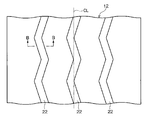
- FIG. 1B is a cross-sectional view of the tread shown in FIG. 1A along the line AA. It is a top view of the tread which has the circumferential groove
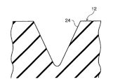
- FIG. 2B is a cross-sectional view of the tread shown in FIG. 2A along the line BB. It is a top view of the tread which has the conventional linear circumferential groove
- FIG. 3B is a cross-sectional view taken along the line CC of the tread shown in FIG. 3A.
- a pneumatic tire 10 according to an embodiment of the present invention will be described with reference to FIG.
- three circumferential grooves 14 extending continuously in the tire circumferential direction are formed in the tread 12 of the pneumatic tire 10 of the present embodiment.
- One of the three circumferential grooves 14 is disposed on the tire equator plane CL, and the other is disposed on both sides of the tire equator plane CL.
- the circumferential groove 14 of the present embodiment is formed on the tread 12 side of the tread 12 and extends in a zigzag shape along the tire circumferential direction, and is formed on the groove bottom side and linearly along the tire circumferential direction.
- the second groove portion 18 extends.
- a step portion 20 is formed at a boundary portion between the second groove portion 18 and the first groove portion 16 in the intermediate portion in the groove depth direction.
- a ⁇ B where A is the groove depth of the first groove portion 16 and B is the groove depth of the second groove portion 18.
- A is the groove depth of the first groove portion 16
- B is the groove depth of the second groove portion 18.
- the groove width Z of the circumferential groove 14 on the center side is a tire. It is preferable to set the measurement in the width direction to be equal to or greater than the groove width Z of the circumferential grooves 14 on both sides.
- the groove width of the first groove portion 16 is Z (the opening is measured in the tire width direction), and the groove width of the second groove portion 18 is S (the opening is measured in the tire width direction).
- the groove width ratio S / Z in the central circumferential groove 14 is preferably set equal to or greater than the groove width ratio S / Z in the circumferential grooves 14 on both sides.
- the groove width ratio S / Z in the central circumferential groove 14 is equal to or greater than the circumferential grooves 14 on both sides. It is preferable to satisfy the relationship of the groove width ratio S / Z.
- action of the pneumatic tire 10 of this embodiment is demonstrated. Since the circumferential groove 14 of the pneumatic tire 10 of the present embodiment is provided with the first groove portion 16 on the tread surface side and the second groove portion 18 on the groove bottom side, the wet road surface has a relatively shallow water depth. When traveling on the road, the edge (edge component in the tire width direction) of the first groove portion 16 effectively exerts a catching effect (edge effect) with the road surface, and high wet braking performance is obtained.
- the linear second groove portion 18 preferably has a large groove volume and a passage for the groove for draining. Further, the center side in the tire width direction of the contact surface is a portion that is more difficult to drain than the shoulder side.
- three circumferential grooves 14 are formed in the tread 12 to form a tread.
- the groove width of the circumferential groove 14 arranged on the center side in the width direction is equal to or greater than the groove width of the circumferential grooves 14 on both sides, the drainage performance on the center side in the tire width direction of the ground contact surface can be improved.
- the groove width ratio S / Z in the circumferential groove 14 on the central side is equal to or greater than the groove width ratio S / Z in the circumferential grooves 14 on both sides.
- the volume of the groove portion 18 is relatively greater than or equal to the volume of the second groove portion 18 of the circumferential grooves 14 on both sides, and the drainage performance on the center side in the tire width direction where water is difficult to drain at the time of ground contact can be improved.
- the zigzag amplitude of the circumferential groove 14 on the center side is larger than the amplitude of the circumferential grooves 14 on both sides.
- a larger edge effect is obtained than when the zigzag amplitude of the circumferential grooves 14 on both sides is made larger than the amplitude of the circumferential grooves 14 on the center side.
- wet braking performance is improved by changing the groove shape of the circumferential groove 14 between the tread surface side and the groove bottom side, the groove depth is increased, and the negative rate is increased. Since conventional methods such as changing the groove arrangement are not used, the influence on other performance such as wear and passing noise can be suppressed.
- the tread rubber type is reduced in rolling resistance, the braking performance on the wet road surface may be deteriorated.
- the circumferential groove 14 of the form it is possible to suppress a decrease in wet braking performance.
- three circumferential grooves 14 are formed in the tread 12.
- the present invention is not limited to this, and two or four or more grooves may be formed.
- the circumferential groove 14 closest to the tire equatorial plane CL it is preferable to set the circumferential groove 14 closest to the tire equatorial plane CL to be equal to or greater than the groove width of the outermost circumferential groove 14 in the tire width direction.
- the groove width ratio S / Z in the circumferential groove 14 closest to the tire equatorial plane CL is preferably equal to or greater than the groove width ratio S / Z in the circumferential groove 14 on the outermost side in the tire width direction.
- the first groove portion 16 extends in a zigzag shape along the tire circumferential direction.
- the first groove portion 16 only needs to have a groove shape having an amplitude in at least the tire width direction. Other shapes such as a shape may be used.
- Test Example 1 In order to confirm the effect of the present invention, as shown in FIG. 2, one type of tire of Conventional Example 1 in which only the zigzag circumferential groove 22 is provided in the tread 12, as shown in FIG. 3, the linear circumferential direction Comparison of braking performance and drainage performance on a wet road surface by preparing one type of tire of the conventional example 2 having only the groove 24 in the tread 12 and three types of tires of the example to which the present invention is applied. Went.
- the tires of the examples are provided with a circumferential groove including the first groove portion and the second groove portion described in the above embodiment in the tread.
- the dimensions and the like of each part of the tire are as described in Table 1 below.
- W Groove width of circumferential groove (see FIG. 1A, measured in a direction perpendicular to the groove wall)
- ⁇ Swing angle of the groove with respect to the tire circumferential direction (unit: °)
- TW Tread width (see FIG. 1A. Measured in the tire width direction.
- Unit: mm) D Spacing between circumferential grooves (see FIG. 1A. Measured in the tire width direction.
- Braking performance The approach speed to the wet road surface was 100 km / h.
- the braking distance (ABS operation) was measured on the wet road surface, and the evaluation was performed with an index display in which the reciprocal of the braking distance in Conventional Example 1 was set to 100. The larger the value, the better the braking performance.
- Drainage performance (accelerated hydroplaning performance): The vehicle was run on a road with a depth of 6 mm at a speed of 70 km / h and gradually accelerated. The speed at which the tire started to idle was defined as the hydroplaning generation speed. Evaluation was performed with an index display in which the hydroplaning generation speed of Conventional Example 1 was 100. The larger the value, the higher the hydroplaning rate and the better the drainage.
- the tire size is 195 / 80R15, the rim size is 15 ⁇ 6.0 J, the internal pressure is 450 kPa, and the load is equivalent to two passengers.
- the tire of the example to which the present invention is applied has high braking performance regardless of whether the water depth is shallow or deep. Moreover, it turns out that the drainage performance of the tire of the Example to which the present invention is applied is sufficiently secured.
- Test Example 2 In order to confirm the effect of the present invention, groove depths A and B were set as shown in Table 2 below, and a test similar to Test Example 1 was performed.
- Example 1 in which A ⁇ B and Example 2 in which A B are superior in braking performance and drainage performance than the comparative example deviating from the definition of the present invention in which A> B.
- Test Example 3 In order to confirm the effect of the present invention, the ratio of S and Z was set as shown in Table 3 below, and the same test as in Test Example 1 was performed.
Abstract
Description
請求項1の空気入りタイヤでウエット路面を走行すると、トレッドと路面との間の水は周方向溝を介してタイヤ接地面外へと排水される。
第1の溝部は、例えばジグザグ状等、トレッド幅方向の振幅を有してタイヤ周方向に沿って延びているので、タイヤ幅方向に延びるエッジ成分を有している。
ここで、水深が比較的浅いウエット路面を走行すると、第1の溝部のエッジ(タイヤ幅方向のエッジ成分)によって、路面との引っ掛かり効果(エッジ効果)が有効に発揮され、これにより、高いウエット制動性能が得られる。 Next, the operation of the pneumatic tire according to the first aspect will be described.
When the pneumatic tire according to the first aspect travels on a wet road surface, water between the tread and the road surface is drained out of the tire ground contact surface through a circumferential groove.
Since the first groove portion has an amplitude in the tread width direction and extends along the tire circumferential direction, such as a zigzag shape, the first groove portion has an edge component extending in the tire width direction.
Here, when traveling on a wet road surface where the water depth is relatively shallow, the edge effect (edge effect) with the road surface is effectively exhibited by the edge of the first groove (the edge component in the tire width direction). Brake performance is obtained.
接地面のタイヤ幅方向中央側はショルダー側よりも排水し難い部分であるため、トレッドに周方向溝を3本形成して、トレッド幅方向中央側に配置される周方向溝の溝幅を両側の周方向溝の溝幅以上に設定することが好ましい。これにより、接地面のタイヤ幅方向中央側における排水性能を向上することができる。 Next, the operation of the pneumatic tire according to the second aspect will be described.
Since the center side in the tire width direction of the contact surface is more difficult to drain than the shoulder side, three circumferential grooves are formed in the tread, and the groove widths of the circumferential grooves arranged on the tread width direction center side are both sides. It is preferable to set it equal to or greater than the groove width of the circumferential groove. Thereby, the drainage performance in the tire width direction center side of a contact surface can be improved.
中央の周方向溝における溝幅比S/Zを、両側の周方向溝における溝幅比S/Zと同等以上とすることで、中央の周方向溝の第2の溝部のボリュームが、相対的に両側の周方向溝の第2の溝部のボリューム以上となり、接地時に水が抜け難いタイヤ幅方向中央側における排水性能を向上することが出来る。 Next, the operation of the pneumatic tire according to the third aspect will be described.
By making the groove width ratio S / Z in the central circumferential groove equal to or greater than the groove width ratio S / Z in the circumferential grooves on both sides, the volume of the second groove portion of the central circumferential groove is relatively Further, the drainage performance at the center side in the tire width direction can be improved because it is more than the volume of the second groove portion of the circumferential grooves on both sides, and the water does not easily drain when contacting the ground.
また、溝深さを深くする、ネガティブ率を大きくする、溝配置を変更する等の従来の手法では、摩耗や通過騒音が悪化するなど他性能への影響が起こることが問題となっていたが、本発明では踏面側と溝底側とで溝形状を変える構成としているので、ウエット制動性能を向上しているにも関わらず、他性能への影響が抑えられている。また、転がり抵抗の低減化を実現するために、トレッドのゴム種を転がり抵抗の少ないものにした場合、ウエット路面での制動性能が悪化してしまう場合があるが、本発明を適用することで、トレッドに転がり抵抗の少ないゴムを用いた際のウエット制動性能の低下を抑えることが可能となる。 As described above, since the pneumatic tire according to the first aspect has the above-described configuration, it has an excellent effect that high wet braking performance can be obtained without deteriorating other performance.
In addition, conventional methods such as increasing the groove depth, increasing the negative rate, and changing the groove arrangement have caused problems such as wear and passing noise, which may affect other performance. In the present invention, since the groove shape is changed between the tread surface side and the groove bottom side, the influence on the other performance is suppressed despite the improvement of the wet braking performance. In addition, in order to realize a reduction in rolling resistance, when the tread rubber type is made to have a low rolling resistance, the braking performance on the wet road surface may be deteriorated, but by applying the present invention, In addition, it is possible to suppress a decrease in wet braking performance when rubber having a low rolling resistance is used for the tread.
図1A,Bに示すように、本実施形態の空気入りタイヤ10のトレッド12には、タイヤ周方向に連続して延びる周方向溝14が3本形成されている。
3本の周方向溝14の内の1本はタイヤ赤道面CL上に配置され、その他はタイヤ赤道面CLの両側に配置されている。 A
As shown in FIGS. 1A and 1B, three
One of the three
なお、周方向溝14には、溝深さ方向中間部に、第2の溝部18と第1の溝部16との境界部分に段部20が形成されている。 The
In the
図1Aに示すように、本実施形態の様にトレッド12に周方向溝14を3本形成(または3本以上形成)した場合、中央側の周方向溝14の溝幅Z(開口部をタイヤ幅方向に計測)を、両側の周方向溝14の溝幅Z以上に設定することが好ましい。 As shown in FIG. 1B, it is preferable to set A ≦ B, where A is the groove depth of the
As shown in FIG. 1A, when three
次に、本実施形態の空気入りタイヤ10の作用を説明する。
本実施形態の空気入りタイヤ10の周方向溝14は、踏面側に第1の溝部16が設けられ、溝底側に第2の溝部18が設けられているため、水深が比較的浅いウエット路面を走行する際には、第1の溝部16のエッジ(タイヤ幅方向のエッジ成分)によって、路面との引っ掛かり効果(エッジ効果)が有効に発揮され、高いウエット制動性能が得られる。 (Function)
Next, the effect | action of the
Since the
なお、第1の溝部16は、タイヤ踏面のジグザグ状のエッジが制動性を高める効果があるため、溝ボリュームはそれほど多くは必要とはしないが、エッジ圧を高めるためには、Aは低い方が好ましい。一方、直線状の第2の溝部18は、ハイドロプレーニング性能を確保するためには、溝ボリュームを多くとり、排水するための溝の通り道を確保することが好ましい。
また、接地面のタイヤ幅方向中央側はショルダー側よりも排水し難い部分であるが、本実施形態の空気入りタイヤ10の様に、トレッド12に周方向溝14を3本形成して、トレッド幅方向中央側に配置される周方向溝14の溝幅を両側の周方向溝14の溝幅以上に設定することで、接地面のタイヤ幅方向中央側における排水性能を向上することができる。 Here, by setting the groove depth B of the
In addition, since the zigzag edge of the tire tread surface has an effect of improving the braking performance, the
Further, the center side in the tire width direction of the contact surface is a portion that is more difficult to drain than the shoulder side. However, like the
周方向溝14が4本以上形成されている場合には、タイヤ赤道面CLに最も近い周方向溝14を、タイヤ幅方向最外側の周方向溝14の溝幅以上に設定することが好ましく、タイヤ赤道面CLに最も近い周方向溝14における溝幅比S/Zを、タイヤ幅方向最外側の周方向溝14における溝幅比S/Zと同等以上とすることが好ましい。
上記実施形態では、第1の溝部16がタイヤ周方向に沿ってジグザグ状に延びていたが、第1の溝部16は少なくともタイヤ幅方向に振幅を有する溝形状であれば良く、例えば、サイン波形状等の他の形状であっても良い。 In the above embodiment, three
When four or more
In the above embodiment, the
本発明の効果を確かめるために、図2に示すように、ジグザグ状の周方向溝22のみをトレッド12に備えた従来例1のタイヤ1種、図3に示すように、直線状の周方向溝24のみをトレッド12に備えた従来例2のタイヤ1種、及び本発明の適用された実施例のタイヤ3種を用意し、実車に装着してウエット路面における制動性能、及び排水性能の比較を行った。 (Test Example 1)
In order to confirm the effect of the present invention, as shown in FIG. 2, one type of tire of Conventional Example 1 in which only the zigzag
タイヤ各部の寸法等は、以下の表1内に記載した通りである。
A:周方向溝の第1の溝部の溝深さ(図1B参照。単位:mm。)
B:周方向溝の第2の溝部の溝深さ(図1B参照。単位:mm。)
W:周方向溝の溝幅(図1A参照。溝壁に対して垂直方向に計測。)
θ:タイヤ周方向に対する溝の振り角(単位:°)
S:第2の溝部の溝幅(図1B参照。タイヤ幅方向に計測。単位:mm)
Z:第1の溝部の溝幅(図1B参照。タイヤ幅方向に計測。単位:mm)
TW:トレッドの幅(図1A参照。タイヤ幅方向に計測。単位:mm)
D:周方向溝の間隔(図1A参照。タイヤ幅方向に計測。単位:mm) The tires of the examples are provided with a circumferential groove including the first groove portion and the second groove portion described in the above embodiment in the tread.
The dimensions and the like of each part of the tire are as described in Table 1 below.
A: Groove depth of the first groove portion of the circumferential groove (see FIG. 1B, unit: mm)
B: Groove depth of the second groove portion of the circumferential groove (see FIG. 1B, unit: mm)
W: Groove width of circumferential groove (see FIG. 1A, measured in a direction perpendicular to the groove wall)
θ: Swing angle of the groove with respect to the tire circumferential direction (unit: °)
S: Groove width of the second groove portion (see FIG. 1B. Measured in the tire width direction. Unit: mm)
Z: groove width of the first groove portion (see FIG. 1B, measured in the tire width direction, unit: mm)
TW: Tread width (see FIG. 1A. Measured in the tire width direction. Unit: mm)
D: Spacing between circumferential grooves (see FIG. 1A. Measured in the tire width direction. Unit: mm)
排水性能(加速ハイドロプレーニング性能):水深6mmの路上を70km/hで走行させて徐々に加速させ、タイヤが空転を始めた時の速度をハイドロプレーニング発生速度とした。従来例1のハイドロプレーニング発生速度を100とする指数表示で評価を行った。数値の大きい方がハイドロプレーニング発生速度が高く、排水性に優れていることを表している。
なお、タイヤサイズは195/80R15であり、リムサイズは15×6.0J、内圧は450kPa、荷重は2名乗車相当である。 Braking performance: The approach speed to the wet road surface was 100 km / h. The braking distance (ABS operation) was measured on the wet road surface, and the evaluation was performed with an index display in which the reciprocal of the braking distance in Conventional Example 1 was set to 100. The larger the value, the better the braking performance.
Drainage performance (accelerated hydroplaning performance): The vehicle was run on a road with a depth of 6 mm at a speed of 70 km / h and gradually accelerated. The speed at which the tire started to idle was defined as the hydroplaning generation speed. Evaluation was performed with an index display in which the hydroplaning generation speed of Conventional Example 1 was 100. The larger the value, the higher the hydroplaning rate and the better the drainage.
The tire size is 195 / 80R15, the rim size is 15 × 6.0 J, the internal pressure is 450 kPa, and the load is equivalent to two passengers.

本発明の効果を確かめるために、溝深さA,Bを下記の表2のように設定し、試験例1と同様の試験を行った。 (Test Example 2)
In order to confirm the effect of the present invention, groove depths A and B were set as shown in Table 2 below, and a test similar to Test Example 1 was performed.

本発明の効果を確かめるために、S,Zの比率を下記の表3のように設定し、試験例1と同様の試験を行った。

In order to confirm the effect of the present invention, the ratio of S and Z was set as shown in Table 3 below, and the same test as in Test Example 1 was performed.
10 空気入りタイヤ
12 トレッド
14 周方向溝
16 第1の溝部
18 第2の溝部 DESCRIPTION OF
Claims (3)
- タイヤ周方向に沿って延びる周方向溝をトレッドに備え、
前記周方向溝は、トレッド踏面側に形成されトレッド幅方向の振幅を有するタイヤ周方向に沿って延びる第1の溝部と、前記第1の溝部の溝底側に形成されタイヤ周方向に沿って直線状に延びる第2の溝部とを含んで構成され、
前記第1の溝部の溝深さをA、前記第2の溝部の溝深さをBとしたときに、A≦Bに設定されている、空気入りタイヤ。 The tread has a circumferential groove extending along the tire circumferential direction,
The circumferential groove is formed on the tread tread surface side and extends along the tire circumferential direction having an amplitude in the tread width direction, and is formed on the groove bottom side of the first groove part along the tire circumferential direction. A second groove portion extending linearly, and
A pneumatic tire, wherein A ≦ B, where A is a groove depth of the first groove portion and B is a groove depth of the second groove portion. - 前記トレッドに前記周方向溝が3本形成され、
中央の前記周方向溝の溝幅が、両側の前記周方向溝の溝幅以上に設定されている、請求項1に記載の空気入りタイヤ。 Three circumferential grooves are formed in the tread,
The pneumatic tire according to claim 1, wherein a groove width of the central circumferential groove is set to be equal to or greater than a groove width of the circumferential grooves on both sides. - 前記第1の溝部の溝幅をZ、前記第2の溝部の溝幅をSとしたときに、中央の前記周方向溝における溝幅比S/Z≧両側の前記周方向溝における溝幅比S/Zに設定されている、請求項2に記載の空気入りタイヤ。
When the groove width of the first groove portion is Z and the groove width of the second groove portion is S, the groove width ratio S / Z in the central circumferential groove is equal to or greater than the groove width ratio in the circumferential grooves on both sides. The pneumatic tire according to claim 2, which is set to S / Z.
Priority Applications (4)
| Application Number | Priority Date | Filing Date | Title |
|---|---|---|---|
| US13/394,500 US9561693B2 (en) | 2009-09-07 | 2010-09-06 | Pneumatic tire with tread having circumferential grooves |
| CN201080039631.4A CN102481809B (en) | 2009-09-07 | 2010-09-06 | Pneumatic tire |
| JP2011529972A JP5878372B2 (en) | 2009-09-07 | 2010-09-06 | Pneumatic tire |
| EP10813835.5A EP2465705B1 (en) | 2009-09-07 | 2010-09-06 | Pneumatic tire |
Applications Claiming Priority (2)
| Application Number | Priority Date | Filing Date | Title |
|---|---|---|---|
| JP2009206059 | 2009-09-07 | ||
| JP2009-206059 | 2009-09-07 |
Publications (1)
| Publication Number | Publication Date |
|---|---|
| WO2011027889A1 true WO2011027889A1 (en) | 2011-03-10 |
Family
ID=43649422
Family Applications (1)
| Application Number | Title | Priority Date | Filing Date |
|---|---|---|---|
| PCT/JP2010/065261 WO2011027889A1 (en) | 2009-09-07 | 2010-09-06 | Pneumatic tire |
Country Status (5)
| Country | Link |
|---|---|
| US (1) | US9561693B2 (en) |
| EP (1) | EP2465705B1 (en) |
| JP (1) | JP5878372B2 (en) |
| CN (1) | CN102481809B (en) |
| WO (1) | WO2011027889A1 (en) |
Cited By (4)
| Publication number | Priority date | Publication date | Assignee | Title |
|---|---|---|---|---|
| JP2012218555A (en) * | 2011-04-07 | 2012-11-12 | Bridgestone Corp | Pneumatic tire |
| CN103702843A (en) * | 2011-07-27 | 2014-04-02 | 株式会社普利司通 | Tyre |
| WO2016157903A1 (en) * | 2015-04-01 | 2016-10-06 | 株式会社ブリヂストン | Tire |
| JP2022106273A (en) * | 2021-01-06 | 2022-07-19 | 錦湖タイヤ株式会社 | Pneumatic tire |
Families Citing this family (14)
| Publication number | Priority date | Publication date | Assignee | Title |
|---|---|---|---|---|
| TWI488758B (en) * | 2012-09-17 | 2015-06-21 | Cheng Shin Rubber Ind Co Ltd | Tire tread structure with multiple asymmetric surface trenches |
| USD759579S1 (en) * | 2013-11-14 | 2016-06-21 | Continental Reifen Deutschland Gmbh | Tire |
| USD762159S1 (en) * | 2013-11-14 | 2016-07-26 | Continental Reifen Deutschland Gmbh | Tire |
| USD762160S1 (en) * | 2013-11-15 | 2016-07-26 | Continental Reifen Deutschland Gmbh | Tire |
| USD761723S1 (en) * | 2013-11-15 | 2016-07-19 | Continental Reifen Deutschland Gmbh | Tire |
| USD767476S1 (en) * | 2013-11-18 | 2016-09-27 | Continental Reifen Deutschland Gmbh | Tire |
| JP2017024687A (en) * | 2015-07-28 | 2017-02-02 | 住友ゴム工業株式会社 | Pneumatic tire for heavy load |
| CN105291712A (en) * | 2015-10-19 | 2016-02-03 | 正新橡胶(中国)有限公司 | Pneumatic tyre |
| EP3176006B1 (en) * | 2015-11-24 | 2018-06-20 | Sumitomo Rubber Industries Limited | Tire |
| JP6907758B2 (en) * | 2017-06-28 | 2021-07-21 | 住友ゴム工業株式会社 | tire |
| DE102018211946A1 (en) * | 2018-07-18 | 2020-01-23 | Continental Reifen Deutschland Gmbh | Vehicle tires |
| JP2022097867A (en) * | 2020-12-21 | 2022-07-01 | Toyo Tire株式会社 | Pneumatic tire |
| JP2022126526A (en) * | 2021-02-18 | 2022-08-30 | 横浜ゴム株式会社 | tire |
| CN113799549B (en) * | 2021-10-20 | 2023-05-30 | 青岛双星轮胎工业有限公司 | Wear-resistant tire pattern |
Citations (7)
| Publication number | Priority date | Publication date | Assignee | Title |
|---|---|---|---|---|
| JPS5977907A (en) * | 1982-10-26 | 1984-05-04 | Bridgestone Corp | Pneumatic radial tire for heavy duty vehicle |
| JPS6076404A (en) * | 1983-10-03 | 1985-04-30 | Sumitomo Rubber Ind Ltd | Tread pattern for pneumatic tyre for heavy load |
| JPH05606A (en) * | 1991-06-25 | 1993-01-08 | Bridgestone Corp | Pneumatic tire for heavy load |
| JPH08276708A (en) | 1995-04-07 | 1996-10-22 | Yokohama Rubber Co Ltd:The | Pneumatic tire for heavy duty |
| US20030047262A1 (en) * | 2000-05-11 | 2003-03-13 | Michelin Recherche Et Technique S.A. | Asymmetrical vehicle tire with balanced wet and dry performance |
| JP2006051936A (en) * | 2004-08-11 | 2006-02-23 | Hankook Tire Co Ltd | Tread pattern having straight groove with three-dimensional waveform surface |
| JP2007314029A (en) * | 2006-05-25 | 2007-12-06 | Yokohama Rubber Co Ltd:The | Pneumatic tire |
Family Cites Families (13)
| Publication number | Priority date | Publication date | Assignee | Title |
|---|---|---|---|---|
| US2843172A (en) * | 1955-08-15 | 1958-07-15 | Us Rubber Co | Stone rejecting tire tread |
| US4456046A (en) * | 1981-05-11 | 1984-06-26 | Miller Timothy I | High-speed tires |
| JPS6015204A (en) * | 1983-07-08 | 1985-01-25 | Yokohama Rubber Co Ltd:The | Flat tire for travelling at high speed |
| JPS61175104A (en) * | 1985-01-29 | 1986-08-06 | Bridgestone Corp | Radial-ply tire for heavy duty |
| JPH01215604A (en) | 1988-02-23 | 1989-08-29 | Toyo Tire & Rubber Co Ltd | Pneumatic radial tire with cipher on its groove bottom for heavy load |
| JP3098578B2 (en) * | 1991-07-12 | 2000-10-16 | 株式会社ブリヂストン | Pneumatic radial tire for heavy loads |
| JPH06320914A (en) * | 1993-05-18 | 1994-11-22 | Yokohama Rubber Co Ltd:The | Pneumatic radial tire for heavy load |
| JPH0834208A (en) * | 1994-03-14 | 1996-02-06 | Kumho & Co Inc | Pneumatic tire with tread pattern improved in water discharge on rain-wet road surface |
| JP3035172B2 (en) * | 1994-09-26 | 2000-04-17 | 住友ゴム工業株式会社 | Radial tire |
| JP4017503B2 (en) * | 2002-11-19 | 2007-12-05 | 横浜ゴム株式会社 | Pneumatic tire |
| JP3678727B2 (en) * | 2003-01-07 | 2005-08-03 | 住友ゴム工業株式会社 | Pneumatic tire |
| JP2006111088A (en) * | 2004-10-13 | 2006-04-27 | Bridgestone Corp | Pneumatic tire |
| JP4276614B2 (en) * | 2004-11-25 | 2009-06-10 | 住友ゴム工業株式会社 | Pneumatic tire |
-
2010
- 2010-09-06 EP EP10813835.5A patent/EP2465705B1/en not_active Not-in-force
- 2010-09-06 US US13/394,500 patent/US9561693B2/en not_active Expired - Fee Related
- 2010-09-06 CN CN201080039631.4A patent/CN102481809B/en not_active Expired - Fee Related
- 2010-09-06 JP JP2011529972A patent/JP5878372B2/en not_active Expired - Fee Related
- 2010-09-06 WO PCT/JP2010/065261 patent/WO2011027889A1/en active Application Filing
Patent Citations (7)
| Publication number | Priority date | Publication date | Assignee | Title |
|---|---|---|---|---|
| JPS5977907A (en) * | 1982-10-26 | 1984-05-04 | Bridgestone Corp | Pneumatic radial tire for heavy duty vehicle |
| JPS6076404A (en) * | 1983-10-03 | 1985-04-30 | Sumitomo Rubber Ind Ltd | Tread pattern for pneumatic tyre for heavy load |
| JPH05606A (en) * | 1991-06-25 | 1993-01-08 | Bridgestone Corp | Pneumatic tire for heavy load |
| JPH08276708A (en) | 1995-04-07 | 1996-10-22 | Yokohama Rubber Co Ltd:The | Pneumatic tire for heavy duty |
| US20030047262A1 (en) * | 2000-05-11 | 2003-03-13 | Michelin Recherche Et Technique S.A. | Asymmetrical vehicle tire with balanced wet and dry performance |
| JP2006051936A (en) * | 2004-08-11 | 2006-02-23 | Hankook Tire Co Ltd | Tread pattern having straight groove with three-dimensional waveform surface |
| JP2007314029A (en) * | 2006-05-25 | 2007-12-06 | Yokohama Rubber Co Ltd:The | Pneumatic tire |
Non-Patent Citations (1)
| Title |
|---|
| See also references of EP2465705A4 * |
Cited By (10)
| Publication number | Priority date | Publication date | Assignee | Title |
|---|---|---|---|---|
| JP2012218555A (en) * | 2011-04-07 | 2012-11-12 | Bridgestone Corp | Pneumatic tire |
| CN103702843A (en) * | 2011-07-27 | 2014-04-02 | 株式会社普利司通 | Tyre |
| EP2738018A4 (en) * | 2011-07-27 | 2015-07-29 | Bridgestone Corp | Tyre |
| CN103702843B (en) * | 2011-07-27 | 2016-08-31 | 株式会社普利司通 | Tire |
| US9649888B2 (en) | 2011-07-27 | 2017-05-16 | Bridgestone Corporation | Tire |
| WO2016157903A1 (en) * | 2015-04-01 | 2016-10-06 | 株式会社ブリヂストン | Tire |
| JP2016193688A (en) * | 2015-04-01 | 2016-11-17 | 株式会社ブリヂストン | tire |
| US11207925B2 (en) | 2015-04-01 | 2021-12-28 | Bridgestone Corporation | Tire |
| JP2022106273A (en) * | 2021-01-06 | 2022-07-19 | 錦湖タイヤ株式会社 | Pneumatic tire |
| JP7230321B2 (en) | 2021-01-06 | 2023-03-01 | 錦湖タイヤ株式会社 | pneumatic tire |
Also Published As
| Publication number | Publication date |
|---|---|
| JP5878372B2 (en) | 2016-03-08 |
| CN102481809B (en) | 2015-03-11 |
| JPWO2011027889A1 (en) | 2013-02-04 |
| EP2465705A4 (en) | 2013-09-18 |
| EP2465705B1 (en) | 2016-07-27 |
| US9561693B2 (en) | 2017-02-07 |
| US20120160384A1 (en) | 2012-06-28 |
| EP2465705A1 (en) | 2012-06-20 |
| CN102481809A (en) | 2012-05-30 |
Similar Documents
| Publication | Publication Date | Title |
|---|---|---|
| JP5878372B2 (en) | Pneumatic tire | |
| JP5391262B2 (en) | Pneumatic tire | |
| JP5658728B2 (en) | Pneumatic tire | |
| JP6378799B2 (en) | Heavy duty pneumatic tire | |
| JP5291739B2 (en) | Pneumatic tire | |
| JP6438768B2 (en) | Pneumatic tire | |
| JP5181927B2 (en) | Pneumatic tire | |
| JP5314343B2 (en) | Pneumatic tire | |
| JP5496562B2 (en) | Pneumatic tire | |
| JP2009096220A (en) | Pneumatic tire | |
| JP6558297B2 (en) | Pneumatic tire | |
| JP2010023595A (en) | Pneumatic tire | |
| JP5993403B2 (en) | Pneumatic tire | |
| WO2011138939A1 (en) | Tire | |
| JP2010030583A (en) | Pneumatic tire | |
| JP2007161114A (en) | Pneumatic tire | |
| JP2008037139A (en) | Pneumatic tire | |
| JP4402393B2 (en) | Pneumatic tire | |
| JP2004090763A (en) | Tire having asymmetric tread pattern and its installation method | |
| JP6421652B2 (en) | Pneumatic tire | |
| JP5743328B2 (en) | tire | |
| JPWO2015033839A1 (en) | All season tire | |
| JP4755163B2 (en) | Pneumatic tire | |
| JP2012046018A (en) | Pneumatic tire | |
| JP2016074275A (en) | Pneumatic tire |
Legal Events
| Date | Code | Title | Description |
|---|---|---|---|
| WWE | Wipo information: entry into national phase |
Ref document number: 201080039631.4 Country of ref document: CN |
|
| 121 | Ep: the epo has been informed by wipo that ep was designated in this application |
Ref document number: 10813835 Country of ref document: EP Kind code of ref document: A1 |
|
| WWE | Wipo information: entry into national phase |
Ref document number: 2011529972 Country of ref document: JP |
|
| WWE | Wipo information: entry into national phase |
Ref document number: 13394500 Country of ref document: US |
|
| NENP | Non-entry into the national phase |
Ref country code: DE |
|
| REEP | Request for entry into the european phase |
Ref document number: 2010813835 Country of ref document: EP |
|
| WWE | Wipo information: entry into national phase |
Ref document number: 2010813835 Country of ref document: EP |