US9608485B2 - Rotor for rotating electrical machine, rotating electric machine, and method for producing rotor for rotating electrical machine with magnet having surfaces tilted with respect to magnet insertion hole - Google Patents
Rotor for rotating electrical machine, rotating electric machine, and method for producing rotor for rotating electrical machine with magnet having surfaces tilted with respect to magnet insertion hole Download PDFInfo
- Publication number
- US9608485B2 US9608485B2 US14/114,791 US201114114791A US9608485B2 US 9608485 B2 US9608485 B2 US 9608485B2 US 201114114791 A US201114114791 A US 201114114791A US 9608485 B2 US9608485 B2 US 9608485B2
- Authority
- US
- United States
- Prior art keywords
- magnet
- insertion hole
- rotor
- rotor core
- electric machine
- Prior art date
- Legal status (The legal status is an assumption and is not a legal conclusion. Google has not performed a legal analysis and makes no representation as to the accuracy of the status listed.)
- Active, expires
Links
Images


Classifications
-
- H—ELECTRICITY
- H02—GENERATION; CONVERSION OR DISTRIBUTION OF ELECTRIC POWER
- H02K—DYNAMO-ELECTRIC MACHINES
- H02K1/00—Details of the magnetic circuit
- H02K1/06—Details of the magnetic circuit characterised by the shape, form or construction
- H02K1/22—Rotating parts of the magnetic circuit
- H02K1/28—Means for mounting or fastening rotating magnetic parts on to, or to, the rotor structures
-
- H—ELECTRICITY
- H02—GENERATION; CONVERSION OR DISTRIBUTION OF ELECTRIC POWER
- H02K—DYNAMO-ELECTRIC MACHINES
- H02K1/00—Details of the magnetic circuit
- H02K1/06—Details of the magnetic circuit characterised by the shape, form or construction
- H02K1/22—Rotating parts of the magnetic circuit
- H02K1/27—Rotor cores with permanent magnets
- H02K1/2706—Inner rotors
- H02K1/272—Inner rotors the magnetisation axis of the magnets being perpendicular to the rotor axis
- H02K1/274—Inner rotors the magnetisation axis of the magnets being perpendicular to the rotor axis the rotor consisting of two or more circumferentially positioned magnets
- H02K1/2753—Inner rotors the magnetisation axis of the magnets being perpendicular to the rotor axis the rotor consisting of two or more circumferentially positioned magnets the rotor consisting of magnets or groups of magnets arranged with alternating polarity
- H02K1/276—Magnets embedded in the magnetic core, e.g. interior permanent magnets [IPM]
- H02K1/2766—Magnets embedded in the magnetic core, e.g. interior permanent magnets [IPM] having a flux concentration effect
-
- H—ELECTRICITY
- H02—GENERATION; CONVERSION OR DISTRIBUTION OF ELECTRIC POWER
- H02K—DYNAMO-ELECTRIC MACHINES
- H02K1/00—Details of the magnetic circuit
- H02K1/06—Details of the magnetic circuit characterised by the shape, form or construction
- H02K1/22—Rotating parts of the magnetic circuit
- H02K1/27—Rotor cores with permanent magnets
-
- H—ELECTRICITY
- H02—GENERATION; CONVERSION OR DISTRIBUTION OF ELECTRIC POWER
- H02K—DYNAMO-ELECTRIC MACHINES
- H02K15/00—Methods or apparatus specially adapted for manufacturing, assembling, maintaining or repairing of dynamo-electric machines
- H02K15/02—Methods or apparatus specially adapted for manufacturing, assembling, maintaining or repairing of dynamo-electric machines of stator or rotor bodies
- H02K15/03—Methods or apparatus specially adapted for manufacturing, assembling, maintaining or repairing of dynamo-electric machines of stator or rotor bodies having permanent magnets
Definitions
- the present invention relates to rotary electric machine rotors, rotary electric machines themselves, and methods for manufacturing rotary electric machine rotors, and in particular, to a rotary electric machine rotor or the like with a built-in permanent magnet.
- rotors including a built-in permanent magnet are known for rotary electric machines such as motors and power generators.
- This type of rotor is also called an “Interior Permanent Magnet (IPM) type rotor”.
- IPM Interior Permanent Magnet
- a rotor core formed from a cylindrical magnet body includes a magnet insertion hole which extends in an axial direction near an inner side of an outer circumferential surface of the rotor core.
- a permanent magnet is inserted inside the magnet insertion hole and adhesively fixed with a resin material.
- JP 2011-4529 A discloses an IPM type rotor.
- a cylindrical rotor core in which electromagnetic steel plates 1 are laminated internally includes an embedded permanent magnet forming magnetic poles.
- Two end plates are provided at respective ends of the rotor core.
- the rotor core and the magnet are fixed by the end plates.
- Each of the end plates is provided with pawl portions which bend at the outer rim.
- the pawl portions press a part of a side surface of the rotor core. It is described that this rotor can achieve a high-strength structure and effectively suppress leakage flux from the permanent magnet.
- Patent Document 2 JP 2010-183692 A discloses a motor magnet which is inserted in a slot provided in a direction along the axial direction of a rotor. This motor magnet is formed by two or more segment magnets which are stacked in the axial direction of the rotor. An oxide film is formed around each of the segment magnets by the oxidation of the segment magnets.
- JP 2005-94845 A discloses a rotor of a permanent magnet type rotary electric machine in which a permanent magnet is inserted and fixed in a magnet insertion hole of a rotor iron core formed by laminating many annular iron core plate members. It is described that the permanent magnet is formed by two or more unit magnets which are aligned in a line in the axial direction and coated with resin to form a bar shape.
- Patent Document 1 JP 2011-4529 A
- Patent Document 2 JP 2010-183692 A
- Patent Document 3 JP 2005-94845 A
- an insulation film processing may be performed with an oxide film, resin coating, or the like as described in the above Patent Documents 2 and 3. This is because such an insulation film processing is effective in order to improve motor output by suppressing a magnet eddy-current loss, which increases as eddy-current flowing in the axial direction of the rotor via surface and inside of the permanent magnet increases even if the steel plates are insulated from each other, when a conductive permanent magnet directly contacts a rotor core made from, for example, a steel plate laminate.
- the permanent magnet in order to grow or form the oxide film on a surface of a permanent magnet to have a desired thickness, the permanent magnet should be left for two days, for example, in a particular atmosphere (refer to Patent Document 2). Therefore, a cost increase cannot be avoided because of the longer manufacturing period of the permanent magnet.
- An object of the present invention is to provide a rotary electric machine rotor, rotary electric machine itself, and a method for manufacturing a rotary electric machine rotor which can suppress an increase of eddy-current loss through a magnet while eliminating the need for insulation film processing on a magnet surface.
- a rotary electric machine rotor is a rotary electric machine rotor with a built-in magnet.
- the rotary electric machine rotor includes a rotor core with a magnet insertion hole extending inside; a magnet inserted in the magnet insertion hole; and an insulating filler filled between an inner wall of the magnet insertion hole and the magnet to fix the magnet; wherein the magnet is fixed with the filler such that a surface of the magnet inside the magnet insertion hole is tilted with respect to an extending direction of the inner wall of the magnet insertion hole.
- the magnet insertion hole may be formed along an axial direction of the rotor core; the magnet may have an axial cross section of an elongated quadrilateral shape; and the magnet may contact the inner wall of the magnet insertion hole at a corner on one axial end side and at another corner on the other axial end side which is diagonally opposite to the corner on the one axial end side.
- the magnet may also have an axial cross section of a parallelogram shape and axial end surfaces which are flush with axial end surfaces of the rotor core.
- the magnet may have an axial cross section of a rectangular shape.
- the magnet may be segmented into a plurality of magnetic pieces; and the filler may be filled between each of the magnet pieces in an integrated fashion in addition to between the inner wall of the magnet insertion hole and the magnet.
- a rotary electric machine is provided with the rotor having any one of the above structures, and a stator disposed around the rotor.
- a method for manufacturing a rotary electric machine rotor is a manufacturing method of a rotary electric machine rotor with a built-in magnet, including preparing a magnet and a rotor core with a magnet insertion hole extending inside; inserting the magnet into the magnet insertion hole; positioning, in a mold die, the rotor core with the magnet inserted inside; holding the magnet with a portion of the mold die such that a surface of the magnet inside the magnet insertion hole is tilted with respect to an extending direction of an inner wall of the magnet insertion hole; filling an insulating filler between the inner wall of the magnet insertion hole and the magnet through an inlet provided with the mold die to fix the magnet to the rotor core; and assembling, to the shaft, the rotor core in which the magnet is fixed with the filler.
- the magnet may have an axial cross section of a parallelogram shape and axial end surfaces which may be flush with axial end surfaces of the rotor core; and in the holding, flat inner side surfaces of the mold die may abut against axial end surfaces of the rotor core and axial end surfaces of the magnet such that the magnet may be held in a tilted position inside the magnet insertion hole.
- the magnet may have an axial cross section of a rectangular shape; and in the holding, inclined surfaces of protruding portions which protrude on inner side surfaces of the mold die may abut against axial end surfaces of the magnet and press the magnet in an axial direction such that the magnet may be held in a tilted position inside the magnet insertion hole.
- the magnet may have an axial cross section of a rectangular shape; in the holding, inclined surfaces of protruding portions which are elastically provided with the mold die and capable of moving forward and backward may abut corner portions of axial end portions of the magnet and press the axial end portion of the magnet in a direction substantially perpendicular to the axial direction such that the magnet may be held in a tilted position inside the magnet insertion hole.
- a contact area between a magnet and a rotor core is minimized by placing the magnet such that a magnet surface is tilted with respect to the extending direction of an inner wall of a magnet insertion hole.
- FIG. 1 shows a cross-sectional view along an axial direction of a rotary electric machine rotor according to one embodiment of the present invention.
- FIG. 2 shows an axial end surface of the rotor core shown in FIG. 1 .
- FIG. 3 shows an enlarged view of one magnetic pole of the rotor core shown in FIG. 2 .
- FIG. 4 shows a cross sectional view taken along a line A-A in FIG. 3 .
- FIG. 5 shows a cross sectional view similar to FIG. 4 , with an example with a permanent magnet having an axial cross section of a rectangular shape.
- FIG. 6 shows a schematic diagram describing how eddy-current flows into magnetic steel plates forming a rotary core via a surface of a permanent magnet on which no insulation film processing is performed.
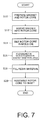
- FIG. 7 shows a flow chart describing a manufacturing method of a rotary electric machine rotor according to the present embodiment.
- FIG. 8 shows a view in which a permanent magnet having an axial cross section of a parallelogram shape is held in a tilted position inside a magnet insertion hole of a rotor core by a mold die.
- FIG. 9 shows a view in which a permanent magnet having an axial cross section of a rectangular shape is held in a tilted position inside a magnet insertion hole of a rotor core by a mold die.
- FIG. 10 shows another example in which a permanent magnet having an axial cross section of a rectangular shape is held in a tilted position inside a magnet insertion hole of a rotor core by a mold die.
- FIG. 11 shows a view similar to FIG. 3 , with a variation of rotary electric machine rotor according to the present invention.
- FIG. 12 shows a view similar to FIG. 3 , with another variation of rotary electric machine rotor according to the present invention.
- FIG. 13 shows a view similar to FIG. 9 , with the rotor core of the variation shown in FIG. 12 set in a mold die.
- Embodiments according to the present invention are described below by referring to the attached drawings.
- specific shapes, materials, numerals, directions, or the like are provided merely as examples in order to facilitate the understanding of the present invention, and can be appropriately changed in accordance with usages, purposes, and specifications. It is assumed from the beginning that when two or more embodiments and variations are included in the description below, the described features of those embodiments will be appropriately combined to be used.
- FIG. 1 is a cross sectional view along the axial direction of a rotary electric machine rotor 10 according to an embodiment of the present invention (hereinafter simply referred to as “rotor”).
- a cylindrical stator 11 is disposed around the rotor 10 with a predetermined gap therebetween to construct a rotary electric machine.
- Two or more teeth are provided at the inner circumference of the stator 11 with an equal space between them such that the teeth protrude towards the inside in a radial direction. Between adjacent teeth, opened slots of the same number as the teeth are provided at the inner circumferential side and at both axial ends.
- Stator coils (not shown) wound around the teeth are inserted in the slots. In this way, when electrical power is applied to the stator coils, a rotating magnetic field which rotates the rotor 10 is formed on the inner side of the stator 11 .
- the rotor 10 is provided with a cylindrical rotor core 12 having a shaft hole 23 at the radial center; a shaft 14 which is fixed so as to penetrate through the shaft hole 23 of the rotor core 12 ; endplates 16 placed to contact both sides of the rotor core 12 in the axial direction (shown with arrow X) of the shaft 14 (and rotor core 12 ); and a fixing member 18 which fixes the rotor core 12 and the endplates 16 to the shaft 14 .
- the rotor core 12 is formed from many electromagnetic steel plates laminated in the axial direction. Each of the electromagnetic steel plates is processed by cutting out an annular plate from silicon steel plates or the like having a thickness of, for example, 0.3 mm.
- the electromagnetic steel plates forming the rotor core 12 are integrally coupled by a method such as crimping, adhering, and welding in blocks in which the rotor core 12 is segmented into two or more blocks in an axial direction, or the electromagnetic steel plates forming the rotor core 12 are integrally coupled the as a whole.
- Each of the electromagnetic steel plates forming the rotor core 12 is electrically insulated from the others by insulation film formed on the surface of the steel plate.
- two or more magnetic poles 24 are equally spaced from each other in a circumferential direction of the rotor core 12 .
- Each of the magnetic poles 24 includes a pair of permanent magnets described in detail below.
- the rotor core 12 is located at a predetermined circumferential position on the shaft 14 by interference fit or key fit.
- the rotor core 12 may be formed from a pressed powder magnetic core made from magnetic powder such as soft magnetic metal powder or soft magnetic metal oxide powder, both of which are coated by resin binder such as silicon resin.
- the soft magnetic metal powder may include iron, iron-silicon based alloy, iron-nitrogen based alloy, iron-nickel based alloy, iron-carbon based alloy, iron-boron based alloy, iron-cobalt based alloy, iron-phosphorus based alloy, iron-nickel-cobalt based alloy, and iron-aluminum-silicon based alloy.
- the shaft 14 is formed from, for example, a round steel bar.
- a flange portion 15 which protrudes outward in the radial direction is formed along the outer circumference. When the rotor 10 is assembled, this flange portion 15 abuts one of the end plates 16 and functions as an abutting portion which determines a position of the rotor core 12 on the shaft 14 in the axial direction.
- Each of the end plates 16 is formed from a circular plate having an outer shape almost identical to the axial end surface of the rotor core 12 . It is preferable that the end plates 16 are formed from a nonmagnetic metal material such as aluminum and copper. The reason for using a nonmagnetic metal material is to suppress a short circuit of magnetic flux at the axial end portions of the permanent magnet forming a magnetic pole. However, as the material is not limited to a metal material as long as the material is nonmagnetic, the endplates 16 may be made from resin. Further, cost may be reduced by making the end plates 16 smaller than the rotor core 12 , or eliminating the end plates 16 .
- the fixing member 18 includes a cylindrical fixing portion 20 which is fixed to the shaft 14 ; and an annular pressing portion 22 which protrudes outwards in a radial direction from one end portion of the fixing portion 20 .
- the fixing member 18 is fixed on the shaft 14 such that with the rotor core 12 and the two end plates 16 being pressed towards the flange portion 15 by the pressing portion 22 , the fixing portion 20 is fixed to the shaft 14 by a fixing method such as crimping, welding, or screwing. In this way, the rotor core 12 is fixed to the shaft 14 together with the end plates 16 .
- FIGS. 2, 3, and 4 show an axial end surface of the rotor core 12
- a cross section of the rotor core 12 vertical to the axial direction has the same structure.
- FIG. 3 shows an enlarged view of one of the magnet poles 24 in FIG. 2 .
- FIG. 4 is a cross sectional view taken along the line A-A in FIG. 3 .
- a shaft hole 23 penetrating through the rotor core 12 is provided, through which the shaft 14 is inserted and fixed.
- the shaft hole 23 has a circular shape and no keys are provided at the edge portion as shown in FIG. 2 .
- keys or key grooves are provided to protrude (or to be recessed) at the edge portion of the shaft hole 23 .
- Two or more magnetic poles 24 are provided equally spaced apart along an outer circumference of the rotor core 12 .
- the present embodiment shows, as an example, eight magnetic poles 24 which are disposed at intervals of 45 degrees in the circumferential direction.
- each magnetic pole 24 has an identical structure except the magnetized direction of the permanent magnet 26 , one magnetic pole 24 is described below.
- Each magnetic pole 24 includes a pair of the permanent magnets 26 .
- Each pair of the permanent magnets 26 is embedded inside the rotor core 12 at a position near to the outer circumferential surface 13 .
- two permanent magnets 26 included in each magnetic pole 24 have an identical shape and size.
- each permanent magnet 26 has an axial end surface (and cross section) of an elongated rectangular shape with two short side surfaces and two long side surfaces.
- the permanent magnet 26 is formed to have substantially the same length as the rotor core 12 in the axial direction.
- the shape and the size of the permanent magnet 26 are not limited to the arrangements described above, and each permanent magnet 26 may have different shapes and sizes.
- Each of the pair of the permanent magnets 26 in each of the magnetic poles 24 is inserted and fixed in a magnet insertion hole 32 .
- the two permanent magnets 26 are arranged in a substantially V-shape opening towards the outer circumferential surface 13 of the rotor core 12 .
- Each of the pair of the permanent magnets 26 is arranged to be symmetrical about the magnetic pole center line C which is a line drawn in a radial direction passing through the circumferential center of the magnetic pole.
- the pair of the permanent magnets 26 are not limited to this arrangement and each of the pair of the permanent magnets 26 may be arranged asymmetrically about the magnetic pole center line C.
- a first polarity is magnetized on one of the two long side surfaces which is on the outer side in the radial direction, while a second polarity which is different from the first polarity is magnetized on the other long side surface which is on the inner side in the radial direction.
- an N-pole is magnetized on one side surface on the outer side in the radial direction
- an S-pole is magnetized on the other side surface.
- magnetization direction is through the thickness in the direction perpendicular to the two long side surfaces, while the two short side surfaces are arranged along the magnetization direction.
- the magnet insertion hole 32 in which the permanent magnet 26 is inserted includes a magnet enclosure portion 33 c for enclosing the permanent magnet 26 .
- the magnet enclosure portion 33 c is structured to have a rectangular shape substantially identical to but slightly larger than the cross section of the permanent magnet 26 .
- pocket portions 33 a , 33 b are formed at the two circumferential ends of the magnet insertion hole 32 such that the pocket portions 33 a , 33 b extends outwardly from the short side surfaces of the permanent magnet 26 to communicate with the magnet enclosure portion 33 c .
- the pocket portions 33 a , 33 b are formed narrower than the permanent magnet 26 so as to prevent the permanent magnet 26 from entering into the pocket portions 33 a , 33 b.
- the permanent magnet 26 has an axial cross section of an elongated quadrilateral shape. More specifically, the permanent magnet 26 has an axial cross section of an elongated parallelogram shape.
- the magnet insertion hole 32 is formed along the axial direction of the rotor core 12 so as to internally include a rectangular space extending in the axial direction.
- the permanent magnet 26 is arranged in a position in which the long side surfaces 26 a , 26 b (magnet surfaces) inside the magnet insertion hole 32 is tilted with respect to the inner wall of the magnet insertion hole 32 which is arranged parallel to the axial direction.
- the permanent magnet 26 is formed to have an axial length substantially equal to that of the rotor core 12 , axial end surfaces 26 c , 26 d are substantially flush with both of the axial end surfaces of the rotor core 12 . Further, a corner portion 27 a on one axial end side (top in FIG. 4 ) of the permanent magnet 26 and another corner portion 27 b on the other axial end side (bottom in FIG. 4 ) which is diagonally opposite to the corner portion 27 a contact the inner wall of the magnet insertion hole 32 , that is the rotor core 12 .
- the corner portion 27 a is an edge portion defined by the long side surface 26 b and the axial end surface 26 c
- the corner portion 27 b is an edge portion defined by the long side surface 26 a and the axial end surface 26 d.
- spaces having a taper shape extending in the axial direction are respectively formed between the long side surfaces 26 a , 26 b of the permanent magnet 26 which is placed in a tilted position inside the magnet insertion hole 32 and the inner wall of the magnet insertion hole 32 .
- An insulating filler 34 is filled in the space, thereby fixing the permanent magnet 26 inside the magnet insertion hole 32 .
- a resin material having a thermosetting property such as epoxy resin and silicon resin is preferably used.
- a thermoplastic resin material may be used as the filler 34 .
- filler having a high thermal conductivity such as silica filler
- Filler having a high permeability may be mixed with the filler 34 in order to suppress a decline in the amount of magnetic flux from the permanent magnet 26 by enhancing permeability of the filler 34 .
- the filler 34 is filled between the long side surfaces 26 a , 26 b of the permanent magnet 26 and the inner wall of the magnet insertion hole 32 without any gaps, a gap may be left in the filling as long as sufficient adhesive strength of the permanent magnet 26 to the rotor core 12 is achieved.
- the insulating filler 34 is also filled inside the pocket portions 33 a , 33 b of the magnet insertion hole 32 .
- pocket portions 33 a , 33 b of the magnet insertion hole 32 can be assumed to be an area having a relatively low permeability.
- the shape of the permanent magnet 26 is not limited to this shape. As shown in FIG. 5 , the permanent magnet 26 having an axial cross section of a rectangular shape may be used. By applying such a shape to the permanent magnet 26 , it becomes possible to improve yields when manufacturing by cutting out the permanent magnets from magnetic material blocks, achieving lower manufacturing cost.
- FIG. 6 shows a view in which the permanent magnet 26 with conductivity to which insulation film processing is not applied is fixed so as to contact the inner wall of the magnet insertion hole 32 on one side.
- the contact surface 26 b between the permanent magnet 26 and the rotor core 12 becomes conductive with many laminated electromagnet steel plates, being insulated from each other, resulting in a large loop path of eddy-current which flows via the magnet surface 26 a .
- This increases the eddy-current loss of the rotor which rotates in a variable magnetic field, lowering torque rate efficiency in the rotating electric machine.
- the contact portion between the permanent magnet 26 and the rotor core 12 can be limited to a small area, which is the corner portion 27 a on the one axial end side and the corner portion 27 b on the other axial end side.
- the contact portion between the permanent magnet 26 and the rotor core 12 can be limited to, for example, about two or several plates at the two axial ends among the electromagnetic steel plates forming the rotor core 12 . In this way, it becomes possible to avoid forming a large eddy-current loop path in which eddy-current flows to the rotor core 12 via the permanent magnet 26 even when insulation film is not formed on the surface of the permanent magnet 26 .
- the permanent magnet 26 because it becomes possible to use the permanent magnet 26 without the insulation film processing such as oxide coating and resin coating, cost reduction can be achieved because of the reduced period and processes required for manufacturing the permanent magnet 26 .
- FIG. 7 is a flow chart showing a manufacturing process of the rotor 10 .
- step S 10 the permanent magnets 26 and a rotor core 12 in which the magnet insertion holes 32 are formed are prepared.
- step S 12 the permanent magnets 26 are inserted into the magnet insertion holes 32 of the rotor core 12 from the axial direction.
- step S 14 as shown in FIG. 8 , the rotor core 12 with the permanent magnets 26 inserted is set inside a mold die 40 .
- Each of a top die 42 and a bottom die 44 forming the mold die 40 includes a flat inner side surface so as to form a wide surface contacting the axial end surfaces of the rotor core 12 . Because the axial end surfaces 26 c , 26 d of the permanent magnet 26 being flush with the end surfaces of the rotor contact the inner side surfaces of the top die 42 and the bottom die 44 , the permanent magnet 26 is held in a tilted position inside the magnet insertion hole 32 of the rotor core 12 in the subsequent step S 16 .
- step S 18 a resin material is injected into the die from an inlet 43 formed with the top die 42 of the mold die 40 to be filled in the pocket portions 33 a , 33 b of the magnet insertion hole 32 and in a gap between the long side surfaces 26 a , 26 b of the permanent magnet 26 and the inner wall of the magnet insertion hole 32 .
- the permanent magnet 26 is fixed inside the magnet insertion hole 32 of the rotor core 12 .
- the rotor core 12 in which the permanent magnet 26 is fixed as described above is retrieved from the mold die 40 .
- the rotor core 12 is assembled with the shaft 14 , the end plates 16 , and the fixing member 18 . In this way, the manufacture of the rotor 10 is completed.
- FIG. 9 shows a view in which a permanent magnet 26 having an axial cross section of a rectangular shape is held in a tilted position inside the magnet insertion hole 32 of the rotor core 12 by the mold die 40 .
- a protruding portion 46 which corresponds to the magnet insertion hole 32 and has a tilting end surface is provided on each of the inner side surfaces of the top die 42 and the bottom die 44 of the mold die 40 .
- the permanent magnet 26 inserted in the magnet insertion hole 32 is held in a tilted position inside the magnet insertion hole 32 by the tilting end surfaces of the protruding portions 46 which abut and press the axial end surfaces 26 c , 26 d in the axial direction.
- FIG. 10 shows another example in which a permanent magnet 26 having an axial cross section of a rectangular shape is held in a tilted position inside a magnet insertion hole 32 of a rotor core 12 by a mold die 40 .
- pins 48 which are protruding members are respectively provided with the top die 42 and the bottom die 44 of the mold die such that the pins 48 can be moved forward and backward.
- a tapered surface is formed at the tip portion of the pins 48 .
- the pins 48 are pressed towards the inside of the mold die 40 by an elastic member 50 such as a spring or rubber.
- the taper surfaces of the elastically provided pins 48 abut and press the corner portions of the axial end portions of the permanent magnet 26 in a direction substantially perpendicular to the axial direction such that the permanent magnet 26 is held in a tilted position inside the magnet insertion hole 32 . Because the pins 48 are elastically provided so that the pins 48 can be moved forward and backward, excessive contact pressure applied to the permanent magnet 26 by the pins 48 can be avoided, preventing the permanent magnet 26 from being damaged.
- a rotor according to the present invention is not limited to the above embodiments and their variations. Various changes and improvements are possible as long as they do not depart from essentials within the scope of the claims.
- each magnetic pole 24 of the rotor 10 may also be one or more than three.
- one permanent magnet 26 and the other permanent magnet 26 may have different tilted directions inside the magnet insertion hole 32 .
- one permanent magnet 26 may contact the rotor core 12 at the corner on the outer circumferential side, and the other permanent magnet 26 may contact at the corner on the inner circumferential side. In this way, it becomes possible to achieve an advantage that the amount of magnetic flux of one magnetic pole 24 in the axial direction can be leveled.
- each permanent magnet 26 included in the magnetic pole 24 may be segmented into, for example, two or more in the long side surface direction.
- the filler 34 is integrally filled between each of the segmented pieces of the magnet in addition to between the permanent magnet 26 and the magnet insertion hole 32 .
- This can be achieved by providing, between the two magnet pieces placed in the magnet insertion hole 32 a , thin-plate shaped spacers 52 which respectively protrude from the top die 42 and the bottom die 44 as shown in FIG. 13 , and fill the filler 34 in such a condition.
Landscapes
- Engineering & Computer Science (AREA)
- Power Engineering (AREA)
- Manufacturing & Machinery (AREA)
- Permanent Field Magnets Of Synchronous Machinery (AREA)
- Iron Core Of Rotating Electric Machines (AREA)
- Manufacture Of Motors, Generators (AREA)
- Permanent Magnet Type Synchronous Machine (AREA)
Applications Claiming Priority (2)
| Application Number | Priority Date | Filing Date | Title |
|---|---|---|---|
| PLP.394995 | 2011-05-23 | ||
| PCT/JP2011/063245 WO2012169043A1 (ja) | 2011-06-09 | 2011-06-09 | 回転電機用ロータ、回転電機、および、回転電機用ロータの製造方法 |
Publications (2)
| Publication Number | Publication Date |
|---|---|
| US20140077652A1 US20140077652A1 (en) | 2014-03-20 |
| US9608485B2 true US9608485B2 (en) | 2017-03-28 |
Family
ID=47295645
Family Applications (1)
| Application Number | Title | Priority Date | Filing Date |
|---|---|---|---|
| US14/114,791 Active 2032-09-10 US9608485B2 (en) | 2011-06-09 | 2011-06-09 | Rotor for rotating electrical machine, rotating electric machine, and method for producing rotor for rotating electrical machine with magnet having surfaces tilted with respect to magnet insertion hole |
Country Status (8)
| Country | Link |
|---|---|
| US (1) | US9608485B2 (ru) |
| EP (1) | EP2722968B1 (ru) |
| JP (1) | JP5614501B2 (ru) |
| CN (1) | CN103597714B (ru) |
| AU (1) | AU2011370188B2 (ru) |
| BR (1) | BR112013031443B1 (ru) |
| RU (1) | RU2554119C1 (ru) |
| WO (1) | WO2012169043A1 (ru) |
Cited By (5)
| Publication number | Priority date | Publication date | Assignee | Title |
|---|---|---|---|---|
| US20160056677A1 (en) * | 2014-08-20 | 2016-02-25 | Denso Corporation | Rotor of rotating electrical machine |
| US20160329785A1 (en) * | 2013-02-05 | 2016-11-10 | Hyundai Motor Company | Molding apparatus and method for fixing permanent magnets of rotor |
| US20210265880A1 (en) * | 2020-02-25 | 2021-08-26 | Tdk Corporation | Rotating electrical machine |
| US20220029485A1 (en) * | 2020-07-21 | 2022-01-27 | Hyundai Mobis Co., Ltd. | Rotor for motor |
| US11271459B2 (en) * | 2016-03-28 | 2022-03-08 | Aisin Corporation | Rotor manufacturing method |
Families Citing this family (44)
| Publication number | Priority date | Publication date | Assignee | Title |
|---|---|---|---|---|
| JP5611405B1 (ja) * | 2013-04-17 | 2014-10-22 | 三菱電機株式会社 | 回転電機 |
| DE112013007067T5 (de) * | 2013-05-13 | 2016-01-28 | Mitsubishi Electric Corporation | Rotor mit eingebetteten Magneten für eine drehende elektrische Maschine |
| JP6115448B2 (ja) * | 2013-11-06 | 2017-04-19 | トヨタ自動車株式会社 | 回転電機用ロータの製造方法及び回転電機用ロータ |
| JP5999079B2 (ja) * | 2013-12-13 | 2016-09-28 | トヨタ自動車株式会社 | 回転電機ロータ |
| JP6403982B2 (ja) | 2014-04-30 | 2018-10-10 | マブチモーター株式会社 | ブラシレスモータ |
| JP5818949B2 (ja) * | 2014-07-03 | 2015-11-18 | 三菱電機株式会社 | 回転電機 |
| JP2016073056A (ja) * | 2014-09-29 | 2016-05-09 | トヨタ自動車株式会社 | ロータの製造方法 |
| WO2016147211A1 (ja) * | 2015-03-13 | 2016-09-22 | 黒田精工株式会社 | 磁石埋め込み型コアの樹脂充填方法および樹脂充填装置 |
| KR102401352B1 (ko) * | 2015-03-31 | 2022-05-24 | 엘지이노텍 주식회사 | 로터 및 그 제조방법, 상기 로터를 포함하는 모터 |
| JP6480789B2 (ja) * | 2015-04-13 | 2019-03-13 | 本田技研工業株式会社 | 回転電機のロータ |
| JP6233355B2 (ja) * | 2015-06-23 | 2017-11-22 | トヨタ自動車株式会社 | ロータ |
| JPWO2017038326A1 (ja) * | 2015-09-02 | 2018-02-22 | 日立オートモティブシステムズ株式会社 | 回転子、これを備えた回転電機、及び回転子の製造方法 |
| JP6459869B2 (ja) * | 2015-09-08 | 2019-01-30 | トヨタ自動車株式会社 | 樹脂注入方法 |
| DE102016201281B3 (de) * | 2016-01-28 | 2017-05-24 | Continental Automotive Gmbh | Befestigung eines Permanentmagnets innerhalb eines Rotorblechpakets |
| DE102016201970A1 (de) * | 2016-02-10 | 2017-08-10 | Robert Bosch Gmbh | Elektrische Maschine |
| JP6383746B2 (ja) * | 2016-03-10 | 2018-08-29 | 本田技研工業株式会社 | 回転電機のロータ及びその製造方法 |
| DE112016003500T5 (de) * | 2016-03-16 | 2018-06-28 | Fuji Electric Co., Ltd. | Elektrische drehstrommaschine mit permanentmagnet und herstellungsverfahren derselben |
| RU2610305C1 (ru) * | 2016-03-25 | 2017-02-09 | Федеральное Государственное Автономное Образовательное Учреждение Высшего Профессионального Образования "Дальневосточный Федеральный Университет" (Двфу) | Ротор электромашины |
| JP6095827B1 (ja) * | 2016-04-14 | 2017-03-15 | 三菱電機株式会社 | 回転電機用回転子の製造方法 |
| CN106026558A (zh) * | 2016-06-29 | 2016-10-12 | 无锡新大力电机有限公司 | 一种永磁电机的制造工艺 |
| US11050310B2 (en) * | 2016-07-11 | 2021-06-29 | Mitsubishi Electric Corporation | Rotor, motor, fan, compressor, and air conditioning apparatus |
| JP6597594B2 (ja) * | 2016-12-27 | 2019-10-30 | トヨタ自動車株式会社 | 回転子製造装置 |
| JP6627784B2 (ja) | 2017-01-11 | 2020-01-08 | トヨタ自動車株式会社 | 回転電機ロータ |
| JP6740940B2 (ja) * | 2017-03-16 | 2020-08-19 | トヨタ自動車株式会社 | 回転電機のロータ |
| WO2018189822A1 (ja) * | 2017-04-12 | 2018-10-18 | 三菱電機株式会社 | Ipmロータ |
| JP6787257B2 (ja) * | 2017-06-06 | 2020-11-18 | 株式会社デンソー | 回転電機 |
| CN110870168B (zh) * | 2017-06-29 | 2021-10-26 | 日立安斯泰莫株式会社 | 旋转电机 |
| CN107370266B (zh) * | 2017-08-01 | 2023-10-13 | 珠海格力节能环保制冷技术研究中心有限公司 | 电机转子、电机及电机转子的制作方法 |
| DE102017214309A1 (de) * | 2017-08-17 | 2019-02-21 | Continental Automotive Gmbh | Rotor für eine elektrische Maschine, insbesondere eines Kraftfahrzeugs, sowie Verfahren zum Herstellen eines solchen Rotors |
| JP2019068523A (ja) * | 2017-09-28 | 2019-04-25 | 日本電産株式会社 | モータ |
| JP6901371B2 (ja) * | 2017-10-03 | 2021-07-14 | トヨタ自動車株式会社 | 回転電機のロータ |
| JP6874630B2 (ja) * | 2017-10-05 | 2021-05-19 | トヨタ自動車株式会社 | 回転電機ロータ及びその製造方法 |
| US11435092B2 (en) | 2017-12-07 | 2022-09-06 | Mitsubishi Electric Corporation | Rotor, electric motor, compressor, air conditioner, and manufacturing method of rotor |
| US11336159B2 (en) * | 2018-01-11 | 2022-05-17 | Aisin Corporation | Manufacturing method of rotor |
| JP2019134565A (ja) * | 2018-01-30 | 2019-08-08 | 本田技研工業株式会社 | 回転電機のロータ |
| US20190326790A1 (en) * | 2018-04-24 | 2019-10-24 | GM Global Technology Operations LLC | Brushless starter rotor assembly |
| JP2020014300A (ja) * | 2018-07-17 | 2020-01-23 | 本田技研工業株式会社 | ロータユニット |
| CN109450135B (zh) * | 2018-11-15 | 2023-12-08 | 珠海格力节能环保制冷技术研究中心有限公司 | 一种转子铁芯、转子及电机 |
| JP7132857B2 (ja) * | 2019-01-09 | 2022-09-07 | 本田技研工業株式会社 | 永久磁石埋設型ロータ及び永久磁石埋設型ロータの製造方法 |
| JP7132143B2 (ja) * | 2019-02-05 | 2022-09-06 | ファナック株式会社 | ロータコアの製造装置及びロータコアの製造方法 |
| JP7395869B2 (ja) | 2019-08-08 | 2023-12-12 | トヨタ自動車株式会社 | 埋込磁石型のロータの製造方法 |
| JPWO2021200708A1 (ru) * | 2020-03-31 | 2021-10-07 | ||
| JP7283447B2 (ja) * | 2020-06-11 | 2023-05-30 | トヨタ自動車株式会社 | ロータの製造方法およびロータ製造装置 |
| JP2022139323A (ja) * | 2021-03-11 | 2022-09-26 | 本田技研工業株式会社 | ロータ、回転電機、ロータの製造方法および磁石 |
Citations (9)
| Publication number | Priority date | Publication date | Assignee | Title |
|---|---|---|---|---|
| DE19737391A1 (de) | 1997-08-27 | 1999-03-04 | Magnet Motor Gmbh | Elektrische Maschine, deren Rotor aus Dauermagneten und Magnetfluß-Leitstücken aufgebaut ist |
| JP2002238190A (ja) | 2001-02-06 | 2002-08-23 | Mitsubishi Electric Corp | 永久磁石形電動機の回転子及び永久磁石形電動機の回転子の製造方法及び永久磁石形電動機及び圧縮機及び冷凍サイクル |
| JP2005094845A (ja) | 2003-09-12 | 2005-04-07 | Toshiba Industrial Products Manufacturing Corp | 永久磁石式回転電機の回転子 |
| JP2008109777A (ja) | 2006-10-25 | 2008-05-08 | Toyota Motor Corp | ロータ、回転電動機およびロータの製造方法 |
| WO2008154358A1 (en) | 2007-06-07 | 2008-12-18 | Novatorque, Inc. | Conical magnets and rotor-stator structures for electrodynamic machines |
| US20090045689A1 (en) | 2006-03-13 | 2009-02-19 | Toyota Jidosha Kabushiki Kaisha | Rotor and method of manufacturing the same and electric vehicle |
| JP2010183692A (ja) | 2009-02-04 | 2010-08-19 | Toyota Motor Corp | モータ用磁石とipmモータ用ロータ、およびipmモータ |
| JP2010206882A (ja) | 2009-03-02 | 2010-09-16 | Mitsubishi Electric Corp | 電動機及び圧縮機及び空気調和機及び電気掃除機 |
| JP2011004529A (ja) | 2009-06-18 | 2011-01-06 | Toyota Motor Corp | Ipmモータ用ロータとipmモータ |
Family Cites Families (6)
| Publication number | Priority date | Publication date | Assignee | Title |
|---|---|---|---|---|
| JPH11252838A (ja) * | 1998-03-02 | 1999-09-17 | Nissan Motor Co Ltd | ロータの磁石位置決め方法 |
| JP2005269804A (ja) * | 2004-03-19 | 2005-09-29 | Toyota Motor Corp | 回転電機 |
| RU2386200C2 (ru) * | 2007-08-29 | 2010-04-10 | Государственное образовательное учреждение высшего профессионального образования Дальневосточный государственный технический университет (ДВПИ им. В.В. Куйбышева) | Ротор электрогенератора |
| RU2369953C1 (ru) * | 2007-12-26 | 2009-10-10 | Общество с ограниченной ответственностью "ЭНЕРГИЯ" | Многополюсный ротор вентильной электрической машины с постоянными магнитами (варианты) |
| RU91483U1 (ru) * | 2008-09-10 | 2010-02-10 | Виктор Семенович Ломоносов | Многополюсный магнитный мотор |
| RU2382472C1 (ru) * | 2008-12-01 | 2010-02-20 | Александр Владимирович Левин | Ротор высокооборотной электрической машины |
-
2011
- 2011-06-09 WO PCT/JP2011/063245 patent/WO2012169043A1/ja active Application Filing
- 2011-06-09 CN CN201180071513.6A patent/CN103597714B/zh active Active
- 2011-06-09 JP JP2013519308A patent/JP5614501B2/ja active Active
- 2011-06-09 EP EP11867295.5A patent/EP2722968B1/en active Active
- 2011-06-09 AU AU2011370188A patent/AU2011370188B2/en active Active
- 2011-06-09 US US14/114,791 patent/US9608485B2/en active Active
- 2011-06-09 RU RU2013158180/07A patent/RU2554119C1/ru active
- 2011-06-09 BR BR112013031443-5A patent/BR112013031443B1/pt active IP Right Grant
Patent Citations (10)
| Publication number | Priority date | Publication date | Assignee | Title |
|---|---|---|---|---|
| DE19737391A1 (de) | 1997-08-27 | 1999-03-04 | Magnet Motor Gmbh | Elektrische Maschine, deren Rotor aus Dauermagneten und Magnetfluß-Leitstücken aufgebaut ist |
| US6384504B1 (en) | 1997-08-27 | 2002-05-07 | Magnet-Motor Gesellschaft Für Magnetmotorische Technik Mbh | Electric machine with a rotor constructed of permanent magnets and magnetic flux guides |
| JP2002238190A (ja) | 2001-02-06 | 2002-08-23 | Mitsubishi Electric Corp | 永久磁石形電動機の回転子及び永久磁石形電動機の回転子の製造方法及び永久磁石形電動機及び圧縮機及び冷凍サイクル |
| JP2005094845A (ja) | 2003-09-12 | 2005-04-07 | Toshiba Industrial Products Manufacturing Corp | 永久磁石式回転電機の回転子 |
| US20090045689A1 (en) | 2006-03-13 | 2009-02-19 | Toyota Jidosha Kabushiki Kaisha | Rotor and method of manufacturing the same and electric vehicle |
| JP2008109777A (ja) | 2006-10-25 | 2008-05-08 | Toyota Motor Corp | ロータ、回転電動機およびロータの製造方法 |
| WO2008154358A1 (en) | 2007-06-07 | 2008-12-18 | Novatorque, Inc. | Conical magnets and rotor-stator structures for electrodynamic machines |
| JP2010183692A (ja) | 2009-02-04 | 2010-08-19 | Toyota Motor Corp | モータ用磁石とipmモータ用ロータ、およびipmモータ |
| JP2010206882A (ja) | 2009-03-02 | 2010-09-16 | Mitsubishi Electric Corp | 電動機及び圧縮機及び空気調和機及び電気掃除機 |
| JP2011004529A (ja) | 2009-06-18 | 2011-01-06 | Toyota Motor Corp | Ipmモータ用ロータとipmモータ |
Non-Patent Citations (1)
| Title |
|---|
| Machine translation of JP 2002238190 A (Aug. 2002). * |
Cited By (9)
| Publication number | Priority date | Publication date | Assignee | Title |
|---|---|---|---|---|
| US20160329785A1 (en) * | 2013-02-05 | 2016-11-10 | Hyundai Motor Company | Molding apparatus and method for fixing permanent magnets of rotor |
| US9917493B2 (en) * | 2013-02-05 | 2018-03-13 | Hyundai Motor Company | Method for fixing permanent magnets of rotor |
| US20160056677A1 (en) * | 2014-08-20 | 2016-02-25 | Denso Corporation | Rotor of rotating electrical machine |
| US9876404B2 (en) * | 2014-08-20 | 2018-01-23 | Denso Corporation | Rotor of rotating electrical machine |
| US11271459B2 (en) * | 2016-03-28 | 2022-03-08 | Aisin Corporation | Rotor manufacturing method |
| US20210265880A1 (en) * | 2020-02-25 | 2021-08-26 | Tdk Corporation | Rotating electrical machine |
| US11710994B2 (en) * | 2020-02-25 | 2023-07-25 | Tdk Corporation | Rotating electrical machine |
| US20220029485A1 (en) * | 2020-07-21 | 2022-01-27 | Hyundai Mobis Co., Ltd. | Rotor for motor |
| US11876410B2 (en) * | 2020-07-21 | 2024-01-16 | Hyundai Mobis Co., Ltd. | Rotor for motor |
Also Published As
| Publication number | Publication date |
|---|---|
| BR112013031443B1 (pt) | 2020-02-11 |
| JP5614501B2 (ja) | 2014-10-29 |
| US20140077652A1 (en) | 2014-03-20 |
| CN103597714A (zh) | 2014-02-19 |
| WO2012169043A1 (ja) | 2012-12-13 |
| EP2722968A4 (en) | 2016-02-10 |
| EP2722968A1 (en) | 2014-04-23 |
| AU2011370188B2 (en) | 2015-02-12 |
| RU2554119C1 (ru) | 2015-06-27 |
| AU2011370188A1 (en) | 2013-12-05 |
| EP2722968B1 (en) | 2019-04-10 |
| JPWO2012169043A1 (ja) | 2015-02-23 |
| CN103597714B (zh) | 2015-12-09 |
| BR112013031443A2 (pt) | 2016-12-13 |
Similar Documents
| Publication | Publication Date | Title |
|---|---|---|
| US9608485B2 (en) | Rotor for rotating electrical machine, rotating electric machine, and method for producing rotor for rotating electrical machine with magnet having surfaces tilted with respect to magnet insertion hole | |
| US7294948B2 (en) | Rotor-stator structure for electrodynamic machines | |
| US10050481B2 (en) | Permanent magnet type motor and method for manufacturing permanent magnet type motor | |
| CN103907267B (zh) | 永久磁铁嵌入型电动机的转子、电动机、压缩机和空调机 | |
| JP2015510388A (ja) | 電気機械 | |
| TW201338354A (zh) | 永久磁體機 | |
| JP2013198254A (ja) | 回転子および回転電機 | |
| KR102110788B1 (ko) | 자기 기어 장치 | |
| JP2015133839A (ja) | 磁石埋込型ロータ | |
| JP2012244838A (ja) | 回転電機用ロータ、回転電機、および、回転電機用ロータの製造方法 | |
| JP2014155415A (ja) | 磁石埋込型ロータ及び磁石埋込型ロータの製造方法 | |
| JP5761068B2 (ja) | Ipmモータ用ロータの製造方法 | |
| JP2014017956A (ja) | 割断形成永久磁石及びその製造方法 | |
| JP2014233100A (ja) | 永久磁石式回転電機 | |
| JP6115448B2 (ja) | 回転電機用ロータの製造方法及び回転電機用ロータ | |
| JP4898692B2 (ja) | 電気機械のための回転子−固定子構造 | |
| JP5692105B2 (ja) | Ipmモータ用ロータの製造方法 | |
| US10056792B2 (en) | Interior permanent magnet electric machine | |
| JP2011229329A (ja) | 永久磁石式モータ | |
| JP2014045602A (ja) | Ipmモータ用ロータ | |
| JP2018098936A (ja) | 磁石ユニット | |
| JP2015106946A (ja) | 回転電機ロータ | |
| JP5750995B2 (ja) | 同期電動機 | |
| JP2014090575A (ja) | Ipmモータ用ロータ | |
| US20240039349A1 (en) | Rotary electric machine and manufacturing method therefor |
Legal Events
| Date | Code | Title | Description |
|---|---|---|---|
| AS | Assignment |
Owner name: TOYOTA JIDOSHA KABUSHIKI KAISHA, JAPAN Free format text: ASSIGNMENT OF ASSIGNORS INTEREST;ASSIGNORS:YAMAGISHI, YOSHITADA;WATANABE, YUTA;REEL/FRAME:031512/0496 Effective date: 20131001 |
|
| STCF | Information on status: patent grant |
Free format text: PATENTED CASE |
|
| MAFP | Maintenance fee payment |
Free format text: PAYMENT OF MAINTENANCE FEE, 4TH YEAR, LARGE ENTITY (ORIGINAL EVENT CODE: M1551); ENTITY STATUS OF PATENT OWNER: LARGE ENTITY Year of fee payment: 4 |