US8600657B2 - Vehicle control apparatus - Google Patents
Vehicle control apparatus Download PDFInfo
- Publication number
- US8600657B2 US8600657B2 US12/920,396 US92039609A US8600657B2 US 8600657 B2 US8600657 B2 US 8600657B2 US 92039609 A US92039609 A US 92039609A US 8600657 B2 US8600657 B2 US 8600657B2
- Authority
- US
- United States
- Prior art keywords
- vehicle
- control
- control threshold
- risk level
- threshold value
- Prior art date
- Legal status (The legal status is an assumption and is not a legal conclusion. Google has not performed a legal analysis and makes no representation as to the accuracy of the status listed.)
- Active, expires
Links
- 230000001133 acceleration Effects 0.000 description 13
- 238000010586 diagram Methods 0.000 description 11
- 238000001514 detection method Methods 0.000 description 9
- 238000013459 approach Methods 0.000 description 5
- 230000005484 gravity Effects 0.000 description 4
- 238000000034 method Methods 0.000 description 4
- 208000019901 Anxiety disease Diseases 0.000 description 2
- 230000036506 anxiety Effects 0.000 description 2
- 230000036461 convulsion Effects 0.000 description 2
- 230000007423 decrease Effects 0.000 description 2
- 241000282326 Felis catus Species 0.000 description 1
- 230000003247 decreasing effect Effects 0.000 description 1
- 230000003111 delayed effect Effects 0.000 description 1
- 238000011156 evaluation Methods 0.000 description 1
- 230000012447 hatching Effects 0.000 description 1
- 239000003550 marker Substances 0.000 description 1
- 230000002195 synergetic effect Effects 0.000 description 1
Images


Classifications
-
- B—PERFORMING OPERATIONS; TRANSPORTING
- B60—VEHICLES IN GENERAL
- B60T—VEHICLE BRAKE CONTROL SYSTEMS OR PARTS THEREOF; BRAKE CONTROL SYSTEMS OR PARTS THEREOF, IN GENERAL; ARRANGEMENT OF BRAKING ELEMENTS ON VEHICLES IN GENERAL; PORTABLE DEVICES FOR PREVENTING UNWANTED MOVEMENT OF VEHICLES; VEHICLE MODIFICATIONS TO FACILITATE COOLING OF BRAKES
- B60T7/00—Brake-action initiating means
- B60T7/12—Brake-action initiating means for automatic initiation; for initiation not subject to will of driver or passenger
- B60T7/22—Brake-action initiating means for automatic initiation; for initiation not subject to will of driver or passenger initiated by contact of vehicle, e.g. bumper, with an external object, e.g. another vehicle, or by means of contactless obstacle detectors mounted on the vehicle
-
- B—PERFORMING OPERATIONS; TRANSPORTING
- B60—VEHICLES IN GENERAL
- B60W—CONJOINT CONTROL OF VEHICLE SUB-UNITS OF DIFFERENT TYPE OR DIFFERENT FUNCTION; CONTROL SYSTEMS SPECIALLY ADAPTED FOR HYBRID VEHICLES; ROAD VEHICLE DRIVE CONTROL SYSTEMS FOR PURPOSES NOT RELATED TO THE CONTROL OF A PARTICULAR SUB-UNIT
- B60W30/00—Purposes of road vehicle drive control systems not related to the control of a particular sub-unit, e.g. of systems using conjoint control of vehicle sub-units
- B60W30/08—Active safety systems predicting or avoiding probable or impending collision or attempting to minimise its consequences
- B60W30/09—Taking automatic action to avoid collision, e.g. braking and steering
-
- B—PERFORMING OPERATIONS; TRANSPORTING
- B60—VEHICLES IN GENERAL
- B60W—CONJOINT CONTROL OF VEHICLE SUB-UNITS OF DIFFERENT TYPE OR DIFFERENT FUNCTION; CONTROL SYSTEMS SPECIALLY ADAPTED FOR HYBRID VEHICLES; ROAD VEHICLE DRIVE CONTROL SYSTEMS FOR PURPOSES NOT RELATED TO THE CONTROL OF A PARTICULAR SUB-UNIT
- B60W30/00—Purposes of road vehicle drive control systems not related to the control of a particular sub-unit, e.g. of systems using conjoint control of vehicle sub-units
- B60W30/08—Active safety systems predicting or avoiding probable or impending collision or attempting to minimise its consequences
- B60W30/095—Predicting travel path or likelihood of collision
- B60W30/0956—Predicting travel path or likelihood of collision the prediction being responsive to traffic or environmental parameters
-
- B—PERFORMING OPERATIONS; TRANSPORTING
- B60—VEHICLES IN GENERAL
- B60W—CONJOINT CONTROL OF VEHICLE SUB-UNITS OF DIFFERENT TYPE OR DIFFERENT FUNCTION; CONTROL SYSTEMS SPECIALLY ADAPTED FOR HYBRID VEHICLES; ROAD VEHICLE DRIVE CONTROL SYSTEMS FOR PURPOSES NOT RELATED TO THE CONTROL OF A PARTICULAR SUB-UNIT
- B60W30/00—Purposes of road vehicle drive control systems not related to the control of a particular sub-unit, e.g. of systems using conjoint control of vehicle sub-units
- B60W30/10—Path keeping
- B60W30/12—Lane keeping
-
- B—PERFORMING OPERATIONS; TRANSPORTING
- B62—LAND VEHICLES FOR TRAVELLING OTHERWISE THAN ON RAILS
- B62D—MOTOR VEHICLES; TRAILERS
- B62D15/00—Steering not otherwise provided for
- B62D15/02—Steering position indicators ; Steering position determination; Steering aids
- B62D15/025—Active steering aids, e.g. helping the driver by actively influencing the steering system after environment evaluation
- B62D15/0265—Automatic obstacle avoidance by steering
-
- B—PERFORMING OPERATIONS; TRANSPORTING
- B60—VEHICLES IN GENERAL
- B60T—VEHICLE BRAKE CONTROL SYSTEMS OR PARTS THEREOF; BRAKE CONTROL SYSTEMS OR PARTS THEREOF, IN GENERAL; ARRANGEMENT OF BRAKING ELEMENTS ON VEHICLES IN GENERAL; PORTABLE DEVICES FOR PREVENTING UNWANTED MOVEMENT OF VEHICLES; VEHICLE MODIFICATIONS TO FACILITATE COOLING OF BRAKES
- B60T2201/00—Particular use of vehicle brake systems; Special systems using also the brakes; Special software modules within the brake system controller
- B60T2201/08—Lane monitoring; Lane Keeping Systems
-
- B—PERFORMING OPERATIONS; TRANSPORTING
- B60—VEHICLES IN GENERAL
- B60W—CONJOINT CONTROL OF VEHICLE SUB-UNITS OF DIFFERENT TYPE OR DIFFERENT FUNCTION; CONTROL SYSTEMS SPECIALLY ADAPTED FOR HYBRID VEHICLES; ROAD VEHICLE DRIVE CONTROL SYSTEMS FOR PURPOSES NOT RELATED TO THE CONTROL OF A PARTICULAR SUB-UNIT
- B60W2540/00—Input parameters relating to occupants
- B60W2540/18—Steering angle
-
- B—PERFORMING OPERATIONS; TRANSPORTING
- B60—VEHICLES IN GENERAL
- B60W—CONJOINT CONTROL OF VEHICLE SUB-UNITS OF DIFFERENT TYPE OR DIFFERENT FUNCTION; CONTROL SYSTEMS SPECIALLY ADAPTED FOR HYBRID VEHICLES; ROAD VEHICLE DRIVE CONTROL SYSTEMS FOR PURPOSES NOT RELATED TO THE CONTROL OF A PARTICULAR SUB-UNIT
- B60W2552/00—Input parameters relating to infrastructure
- B60W2552/30—Road curve radius
-
- B—PERFORMING OPERATIONS; TRANSPORTING
- B60—VEHICLES IN GENERAL
- B60W—CONJOINT CONTROL OF VEHICLE SUB-UNITS OF DIFFERENT TYPE OR DIFFERENT FUNCTION; CONTROL SYSTEMS SPECIALLY ADAPTED FOR HYBRID VEHICLES; ROAD VEHICLE DRIVE CONTROL SYSTEMS FOR PURPOSES NOT RELATED TO THE CONTROL OF A PARTICULAR SUB-UNIT
- B60W2556/00—Input parameters relating to data
- B60W2556/45—External transmission of data to or from the vehicle
- B60W2556/50—External transmission of data to or from the vehicle of positioning data, e.g. GPS [Global Positioning System] data
-
- B—PERFORMING OPERATIONS; TRANSPORTING
- B60—VEHICLES IN GENERAL
- B60W—CONJOINT CONTROL OF VEHICLE SUB-UNITS OF DIFFERENT TYPE OR DIFFERENT FUNCTION; CONTROL SYSTEMS SPECIALLY ADAPTED FOR HYBRID VEHICLES; ROAD VEHICLE DRIVE CONTROL SYSTEMS FOR PURPOSES NOT RELATED TO THE CONTROL OF A PARTICULAR SUB-UNIT
- B60W2720/00—Output or target parameters relating to overall vehicle dynamics
- B60W2720/40—Torque distribution
- B60W2720/406—Torque distribution between left and right wheel
Definitions
- the present invention relates to a vehicle control apparatus configured to support driving in which a driver is prevented from having a sense of discomfort.
- a conventional vehicle control apparatus applies a yaw moment to the vehicle to prevent the vehicle from deviating from the driving lane or warns the driver that the vehicle is likely to deviate from the driving lane (see Patent Document 1).
- the vehicle control apparatus can perform lane deviation avoidance control by changing the control quantity of lane deviation avoidance control, for example, a threshold for deviation avoidance control, depending on an obstacle (a parked vehicle or the like) on the road shoulder.
- Patent Document 1 if there is a parked vehicle ahead of the vehicle on the left, the control threshold is set so as to avoid the parked vehicle.
- the vehicle is controlled such that if the control threshold is exceeded, the vehicle is returned to a position where the control threshold is prevented from being exceeded, in accordance with the deviation amount.
- a risky obstacle an oncoming vehicle or the like
- the vehicle is controllably moved toward the oncoming vehicle, disadvantageously providing the driver with a sense of fear or discomfort.
- an object of the present invention is to provide a vehicle control apparatus configured to safely and controllably prevent the driver from having a sense of discomfort during driving even if there are risks ahead of the vehicle on both sides.
- the present invention provides a desirable aspect as follows.
- a vehicle control apparatus includes a calculation section configured to calculate a first risk level present on a left of a vehicle and a second risk level present on a right of the vehicle, a setting section configured to set a first control threshold for the left of the vehicle based on the first risk level and to set a second control threshold for the right of the vehicle based on the second risk level, a change section configured to change at least one of the first and second control thresholds based on the first and second risk levels, and a control section configured to control the vehicle based on the changed control threshold.
- the present invention can provide a vehicle control apparatus configured to controllably allow the vehicle to travel safely while preventing the driver from having a sense of discomfort even if there are risks ahead of the vehicle on both sides.
- FIG. 1 A diagram showing the configuration of a vehicle in which a vehicle control apparatus is mounted.
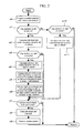
- FIG. 2 A flowchart of the vehicle control apparatus.
- FIG. 3 A diagram showing a control method to which the present embodiment has not been applied yet.
- FIG. 4 A diagram showing a control method to which the present embodiment has been applied.
- FIG. 5 A diagram showing the control quantity of the vehicle control apparatus.
- FIG. 6 A diagram showing vehicle control at a curve.
- FIG. 7 A diagram showing the difference between the present embodiment and the conventional art.
- FIG. 1 is a diagram showing the configuration of a vehicle in which a vehicle control apparatus is mounted.
- the vehicle includes a controller 1 configured to control the vehicle, an operation quantity detection section (steering angle sensor 2 , direction indicator lever 3 , accelerator pedal operation quantity sensor 4 , and brake pedal operation quantity sensor 5 ) configured to detect various operation quantities provided by a driver, a navigation apparatus (hereinafter simply referred to as the navigation) 6 , a motion state detection section (wheel speed sensor 7 and wheel behavior sensor 8 ) configured to detect the motion state of the vehicle, an environment recognition section (camera 10 (front camera 10 f , rear camera 10 r , left front camera 10 f L, right front camera 10 f R, rear left camera 10 r L, and rear right camera 10 r R)) configured to recognize an external environment around the vehicle, a radar 11 (front radar 11 f and rear radar 11 r ), an actuator (engine 21 , electronic control brake 22 , electronic control differential mechanism 23 , and electronic control steering mechanism 24 ), and an information provision section 25 configured to provide the driver with information.
- an operation quantity detection section steering angle sensor 2 , direction indicator lever 3
- the controller 1 is connected to the navigation 6 to acquire a set route, map information, the position and direction of the vehicle on the map, and surrounding lane information (the number of lanes, a speed limit, the difference between a freeway and a general road, the presence or absence of a fork road, the shape of a curve, weather, time, and the like).
- the route may be set by the driver or set (changed) by the navigation 6 based on past driving routes and traffic information.
- the operation quantity detection section transmits a signal corresponding to the operation quantity provided by the driver, to the controller 1 .
- the driver's intension to change the route can be detected in the operation of the direction indicator lever 3 .
- the operation quantities provided by the driver refer to signals corresponding to the steering angle, the state of the direction indicator, the operation quantity of the accelerator pedal, the operation quantity of the brake pedal, and the set route.
- the motion state detection section transmits the motion state amount of the vehicle to the controller 1 .
- the motion state amount refers to a vehicle speed, a yaw rate, a lateral acceleration, a front-rear acceleration, a lateral jerk, and a front-back jerk.
- the environment recognition section transmits information on lane markers and obstacles around the vehicle to the controller 1 .
- the lane markers include lanes (solid line, dashed line, dotted line, and hatching), botts dots, and cats eyes.
- the camera 10 includes an image acquisition section configured to acquire images of surroundings of the vehicle, and a lane recognition section configured to recognize the images acquired.
- the camera 10 outputs state quantities such as the type, acceleration, luminance, color, width, and height of an obstacle or the relative distance and speed between the vehicle and the obstacle.
- the radar 11 also outputs state quantities such as the relative position and speed between the vehicle and the object.
- examples of the obstacle include stationary obstacles such as a road shoulder, a guard rail, a fallen object, a riverbank, a roadside ditch, a median strip, a road sign, a tree, a telephone pole, a house, a wall, curbstone, and a parked vehicle, and mobile obstacles such as another vehicle (a bus, a truck, a traction vehicle, or a crane vehicle), a pedestrian, a bicycle, and a motorbike.
- stationary obstacles such as a road shoulder, a guard rail, a fallen object, a riverbank, a roadside ditch, a median strip, a road sign, a tree, a telephone pole, a house, a wall, curbstone, and a parked vehicle
- mobile obstacles such as another vehicle (a bus, a truck, a traction vehicle, or a crane vehicle), a pedestrian, a bicycle, and a motorbike.
- the rear radar 11 r is characterized by being capable of recognizing a farther obstacle than the rear camera 10 r .
- the rear camera 10 r is characterized by having a wider detection angle and being capable of identifying the obstacle over a wider angle than the rear radar 11 r.
- the controller 1 makes a driving request to the actuator based on the driver's operation quantity and external environment. Furthermore, the controller 1 makes an acceleration request to the engine 21 if the vehicle needs to be accelerated, and makes a deceleration request to the electronic control brake 22 when the vehicle needs to be decelerated. Moreover, if the vehicle needs to be turned, the controller 1 outputs a turning request to at least one of the electronic control brake 22 , the electronic control differential mechanism 23 , and the electronic control steering mechanism 24 .
- the electronic control brake 22 is, for example, a hydraulic brake apparatus capable of independently controlling a braking force applied to each wheel. Upon receiving a turning request, the electronic control brake 22 puts a brake on one of the right and left wheels to apply a yaw moment to the wheels.
- the electronic control differential mechanism 23 is, for example, a mechanism capable of driving an electric motor or a clutch to cause a torque difference between the right and left axles. Upon receiving a turning request, the electronic control differential mechanism 23 causes a torque difference between the right and left axles to apply a yaw moment to the vehicle.
- the electronic control steering mechanism 24 is, for example, a steer-by-wire mechanism. Upon receiving a turning request, the electronic control steering mechanism 24 corrects the actual rudder angle of the wheel independently of the steering wheel to apply a yaw moment to the vehicle.
- the information provision section 25 (a monitor apparatus with a built-in speaker or the like) provides support information by image display or sound or with a warning lamp depending on the type of driving support.
- the information provision section 25 may be installed at a plurality of positions instead of only one position.
- FIG. 2 is a flowchart of the controller 1 , configured to perform driving support control.
- FIG. 3 is a diagram showing that the present embodiment is applied to the case in which there is a parked vehicle ahead of the traveling vehicle on the left.
- FIG. 4 shows that that the present embodiment is applied to the case in which there is an oncoming vehicle approaching the vehicle from ahead on the right.
- the lateral road ends are sensed, and a coordinate system is set such that the center between the ends is defined as an X axis and such that the position of center of gravity of the vehicle is defined as O (0, VOy).
- O the position of center of gravity of the vehicle
- f( ⁇ ) is a function that allows ⁇ and (r) to be determined and can be derived using a vehicle motion model.
- ay may be determined based on an accurate analysis formula instead of using the above-described techniques.
- the controller 1 acquires the operation quantity provided by the driver from the operation quantity detection section and acquires the motion state quantity of the vehicle from the motion state detection section (s 0 ).
- the controller 1 determines whether or not there is any obstacle on the left of the vehicle (s 1 ). Upon determining that there is an obstacle, the controller calculates the left risk level (S 2 ).
- segments C 1 (Cx 1 , 0 ) to C 6 (Cx 6 , 0 ) are set on the X axis.
- the segments are internal information on the camera 10 .
- the intervals between the segments are normally set to several mm.
- Point L 1 (X 1 , Ly 1 ) to point L 6 (X 6 , Ly 6 ) are each a reference point positioned on the left of the vehicle with respect to a straight line passing through points C 1 to C 6 and which is parallel to the (y) axis and an object extracted by the camera.
- the risk level Risk* is an evaluation function that numerically indicates the state of the object *.
- RiskA denotes the state value of the road boundary on the left of the vehicle.
- RiskA denotes the state value of a road boundary on the left of the vehicle.
- RiskB denotes the state value of the road boundary on the right of the vehicle.
- RiskC denotes the state value of the obstacle (parked vehicle) on the left of the vehicle.
- RiskD denotes the state value of the obstacle (oncoming vehicle) on the right of the vehicle.
- control intervention threshold values (TL* for the left and TR* for the right) are set at positions located at predetermined distances (ML* for the left and MR* for the right) from a lane marker or the obstacle.
- ML* varies depending on the corresponding Risk*.
- the reference point L 6 is calculated based on the road width over which the vehicle has traveled.
- the Risk fails to be specified (the camera fails to recognize the object).
- a value may be pre-stored which is to be used when the Risk fails to be specified.
- the controller 1 can determine that the vehicle is completely stopped.
- the RiskC can be calculated using:
- RiskC K_lamp (the lighting state (luminance) of the brake lamp)+K_winker (the lighting state of the direction indicator)+K_tire (the direction of the front wheels of the parked vehicle)
- the obstacle may be classified based on the state quantities (luminance, color, width, height, and the like) and shape of the obstacle.
- a predetermined Risk and a predetermined distance may be set for each type of obstacle so as to be changed based on the shape of the road on which the vehicle is traveling, the weather, and the like. This classification is set with the driver's psychological sense of fear taken into account.
- the distribution of probabilities at which the obstacle collides against the vehicle may be calculated so as to allow the risk level to be calculated based on the probability. For example, if the oncoming vehicle D is detected on the right of the vehicle, the relative speed, the relative acceleration, and the relative position are detected using the front camera 10 f , the front radar 11 f , and the like. The steering angle, yaw rate, speed, acceleration, and the like of the vehicle are then calculated. Then, based on these values, the yaw rate and steering angle of the oncoming vehicle D are calculated.
- a front curve may be detected using the navigation 6 and the turning radius of the curve may be calculated so as to allow the steering angle, yaw rate, lateral acceleration, and the like of the oncoming vehicle D to be calculated.
- the width or height of the oncoming vehicle D may be added to the above-described pieces of information to allow the Risk and predetermined distance to be calculated.
- shaking of the mobile obstacle may be taken into account.
- the driver tends to feel like avoiding approaching too close to the mobile object, so that the predetermined distance may be set to a large value.
- information on the weather and time may be acquired from the navigation 6 so that the predetermined distance may be set to a large value when a driving situation such as snow, rain, or nighttime is sensed.
- the control may be intended for the road shape (curve, straight line, intersection, fork road, ramp, junction, or the like) as described below, instead of the object.
- the apparatus sets the BLy to be a threshold value at which left control intervenes in the vehicle, and proceeds to s 3 .
- the controller determines whether or not there is any obstacle on the right of the vehicle (s 3 ). Upon determining that there is an obstacle, the apparatus calculates the right risk level (s 4 ). If there is no obstacle, the apparatus proceeds to s 7 .
- Point R 1 to R 6 are reference points for the object extracted by the camera; the points R 1 to R 6 are positioned on straight lines passing through points C 1 to C 6 , respectively, and which are parallel to the (y) axis and on the right of the vehicle. Based on these points, the control intervention value for each segment is then calculated. For example, for C 1 , the point corresponding to Ry 1 +MR 1 is calculated, and for C 2 , the point corresponding to Ry 2 +MR 2 is calculated. These points are interpolated to obtain a curve BR.
- the apparatus sets the BRy to be a threshold value at which right control intervenes in the vehicle, and proceeds to s 5 .
- the interpolated curves BL and BR are, for example, straight lines, spline curves, linear variations delayed by a primary filter, or the like.
- a left virtual lane is modified in accordance with the right risk level.
- the control intervention threshold value TL* calculated in s 2 is changed based on the risk level RiskD calculated in s 4 .
- the RiskD is calculated as follows.
- RiskD K_VVd (the speed of the oncoming vehicle D)+K_dY (the relative lateral position (VOy ⁇ VDy) with respect to the vehicle)+K_W (the width (Bd ⁇ And) of the oncoming vehicle D)
- These control intervention threshold values are interpolated to calculate an interpolated curve BL′ corrected in accordance with the RiskD.
- the control intervention threshold value on the BL′ with the X coordinate Px′ is BLy′.
- control intervention threshold value corresponding to the RiskD is calculated in the same manner as that described above.
- the control intervention threshold value for the right of the vehicle is BRy′.
- the control intervention threshold value for the left of the vehicle is changed to be closer to the RiskC to make the control intervention more difficult than before the change.
- the ML* and MR* set in accordance with each obstacle are determined with the avoidance capability of the vehicle taken into account.
- My> ⁇ Ymax is set.
- My ⁇ Ymax is set.
- the apparatus determines whether or not vehicle control needs to be performed (s 7 ). If the front point of interest P is positioned between the left control intervention threshold value BLy′ (if not changed, BLy) and the right control intervention threshold value BRy′ (if not changed, BRy), the apparatus finishes a series of processes. If the front point of interest P is not positioned between the left control intervention threshold value BLy′ and the right control intervention threshold value BRy′, the apparatus proceeds to s 8 .
- a target yaw moment is calculated so as to return the vehicle to between the left control threshold value BLy′ (if not changed, BLy) and the right control intervention threshold value BRy′ (if not changed, BRy).
- the control section controls the vehicle based on the changed control threshold values.
- means for realizing the target yaw moment is selected depending on the situation. For example, to alleviate the driver's sense of discomfort, it is possible to generate a yaw moment using the electronic control differential mechanism 23 and the electronic control steering mechanism 24 instead of using the electronic control brake 22 to decelerate the vehicle.
- the electronic control steering mechanism is used to operate the steering to generate a yaw moment, and the threshold value is changed from BL to BL′ in accordance with the RiskC. Thereafter, if the BL′ is exceeded, not only the electronic control steering mechanism performs a yaw moment operation but a brake is applied only to the right wheel of the vehicle for deceleration to exert a synergetic effect on safety.
- FIG. 5 is a diagram showing the control quantity provided by the vehicle control apparatus.
- FIG. 5(A) shows the positional relationship between the front point of interest P and the left road end PL and the right road end PR, the left control threshold value PBL, and the right control threshold value PBR, as well as the absolute value of the target yaw moment.
- FIG. 5(A) corresponds to the conventional art, which fails to take the right and left risk levels into account.
- FIG. 5(B) shows the positional relationship between the front point of interest P and the left road end PL′ and the right road end PR′, the left control threshold value PBL′, and the right control threshold value PBR′, as well as the absolute value of the target yaw moment.
- FIG. 5(B) corresponds to the present embodiment, which takes the right and left risk levels into account.
- the increase gradients GIl and GIr of the yaw moment are gradually varied to smoothly generate yaw motion, thus enabling implementation of vehicle control hindering the driver from having a sense of discomfort.
- the increase gradient is increased (from GIl to GIl′) with decreasing distance to the road end, thus increasing an area in which the limit capability (Mmax) of the vehicle is generated.
- Mmax limit capability
- the ranges from the PL and PR can be increased (PL′ and PR′). That is, the predetermined distance ML* from the left road end is changed to ML*′ in accordance with the risk level RiskD of the oncoming vehicle D (ML*>ML*′).
- the predetermined distance MR* from the right road end is changed to MR*′ in accordance with the risk level RiskC of the parked vehicle Vehicle C (MR*>MR*′).
- the distance between the PL′ and the PR′ is thus increased. This makes the control intervention difficult to reduce the driver's burden.
- the control intervention threshold value since the increase gradient GIl′ is larger than the increase gradient GIl, the control quantity is increased even though the quantity of deviation from the control intervention threshold value unchanged.
- the vehicle control is performed (s 9 ).
- the vehicle is controlled using at least one of the electronic control differential mechanism 23 , the electronic control steering mechanism 24 , and the electronic control brake 22 .
- a warning sound, a warning, a monitor display, or the like in the information provision section 25 may be used to urge the driver to change the operation.
- FIG. 6 is a diagram showing vehicle control for a curve.
- FIG. 6(A) shows the conventional art
- FIG. 6(B) shows the present embodiment.
- the curve BL of the control intervention threshold value is set in accordance with the risk level RiskA for the left of the vehicle. Furthermore, if the oncoming vehicle D approaches the vehicle from ahead on the right, the curve of the control intervention threshold value is set as shown by BR in accordance with the RiskD of the oncoming vehicle. A yaw moment is applied to the vehicle so as to position the vehicle between the BL and the BR. The vehicle is thus controlled so as to move away from the risk.
- a turning vehicle In general, a turning vehicle is likely to shift outward in the turning direction. A strong tire force needs to be generated in order to conversely shift the vehicle inward in the turning direction.
- the driver when the driver further turns the steering wheel or exerts a force on the vehicle in a direction opposite to that in which the vehicle is turned (a moment M in FIG. 6 ), the vehicle itself may become unstable or the driver may have a sense of anxiety.
- the threshold BL for the turning outward direction is exceeded and the vehicle is controlled so as to travel inward in the turning direction, then in connection with the characteristics of the vehicle observed during turning, the driver is prevented from having a sense of discomfort or fear.
- the present embodiment takes the following into account: the RiskA and the RiskD have been sensed on the respective opposite sides of the vehicle, and the vehicle is traveling around a curve. That is, the BR is set to BR′ that is positioned more inward in the turning direction, and the BL is set to BL′ that is a position almost the same as that of the BL, because the vehicle is traveling around a curve. Thus, the BR is unlikely to be crossed over, thus reducing the frequency of control interventions that apply a moment in the direction opposite to the turning direction. On the other hand, even if the vehicle deviates from the lane toward the BL, a moment is applied in the direction in which the vehicle can be more easily turned, preventing the driver from having a sense of discomfort.
- the straight road and the curve as road shapes have been described.
- the present invention is also applicable to various driving scenes such as a road shape involving a certain risk level, a junction, and an intersection.
- a higher risk level may be set for obstacles that are infrequently seen on highways, for example, a dump truck, a trailer, a crane vehicle, a snow plow, and a special vehicle, which are elements providing the driver with a sense of anxiety. Then, even in the case of an emergency vehicle to which any other vehicles need to give way under the provision of the law, the vehicle can prevent the driver from having a sense of discomfort during driving.
- a higher risk level may be set for an obstacle positioned lower than the vehicle on the front passenger seat side because it is difficult for the driver in the driver's seat to perceive the obstacle. Expansion of assumed driving situations allows provision of a vehicle control apparatus configured to enable safer driving and to hinder the driver from having a sense of discomfort.
- the apparatus may determine that the vehicle cannot travel safely and calculate a deceleration instruction in accordance with the range of the lateral control threshold value. At this time, the apparatus urges, through the information provision section 25 , the driver to decelerate the vehicle or the controller 1 controllably decelerates the vehicle. Moreover, if the speed of the vehicle is lower than an allowable speed set in accordance with the range of the control threshold value, the lateral control threshold value may be permitted to be changed. This enables the driver's sense of operation to be safely made compatible with the risk level.
- FIG. 7 is a diagram showing the difference between the present embodiment and the conventional art.
- FIG. 7(A) shows the present embodiment
- FIG. 7(B) shows the conventional art.
- a vehicle A with the vehicle control apparatus is allowed to move toward an obstacle with a left obstacle risk level RiskL to the degree that the vehicle is controlled.
- FIG. 8(B) at a point X 1 where there is an obstacle with the RiskL on the left of the vehicle and at a point X 2 where there are an obstacle with the RiskL and an obstacle with RiskR on the respective opposite sides of the vehicle, the driving trajectories of the vehicle are as shown by J 1 ′ and J 2 ′, respectively. There appears to be almost no difference between the J 1 ′ and the J 2 ′; in both cases, the vehicle is controllably moved to a similar position.
- FIG. 8(A) under similar driving conditions, the driving trajectories at points X 1 and X 2 are as shown by J 1 and J 2 , respectively.
- a vehicle control apparatus including a calculation section configured to calculate a first risk level (RiskL in FIG. 8 ) present on the left of the vehicle and a second risk level (RiskR in FIG. 8 ) present on the right of the vehicle, a setting section configured to set a first control threshold value (PL in FIG. 8 ) for the left of the vehicle based on the first risk level and to set a second control threshold value for the right of the vehicle based on the second risk level, and a change section configured to change at least one of the first and second control threshold values based on the first and second risk levels (the change results in the ⁇ J).
- PL first control threshold value
- an increase in right RiskR allows the vehicle to pass closer to the obstacle with the RiskL at the point X 2 (the J 2 decreases). Then, an increase in ⁇ J can be confirmed.
Landscapes
- Engineering & Computer Science (AREA)
- Transportation (AREA)
- Mechanical Engineering (AREA)
- Automation & Control Theory (AREA)
- Chemical & Material Sciences (AREA)
- Combustion & Propulsion (AREA)
- Control Of Driving Devices And Active Controlling Of Vehicle (AREA)
- Traffic Control Systems (AREA)
- Steering Control In Accordance With Driving Conditions (AREA)
- Regulating Braking Force (AREA)
- Retarders (AREA)
Applications Claiming Priority (3)
| Application Number | Priority Date | Filing Date | Title |
|---|---|---|---|
| JP2008-240160 | 2008-09-19 | ||
| JP2008240160A JP5070171B2 (ja) | 2008-09-19 | 2008-09-19 | 車両制御装置 |
| PCT/JP2009/063384 WO2010032556A1 (ja) | 2008-09-19 | 2009-07-28 | 車両制御装置 |
Publications (2)
| Publication Number | Publication Date |
|---|---|
| US20110187515A1 US20110187515A1 (en) | 2011-08-04 |
| US8600657B2 true US8600657B2 (en) | 2013-12-03 |
Family
ID=42039398
Family Applications (1)
| Application Number | Title | Priority Date | Filing Date |
|---|---|---|---|
| US12/920,396 Active 2030-02-18 US8600657B2 (en) | 2008-09-19 | 2009-07-28 | Vehicle control apparatus |
Country Status (5)
| Country | Link |
|---|---|
| US (1) | US8600657B2 (de) |
| EP (1) | EP2330009B1 (de) |
| JP (1) | JP5070171B2 (de) |
| CN (1) | CN101959738B (de) |
| WO (1) | WO2010032556A1 (de) |
Cited By (8)
| Publication number | Priority date | Publication date | Assignee | Title |
|---|---|---|---|---|
| US20130013151A1 (en) * | 2009-12-15 | 2013-01-10 | Dr. Ing. h.c. F Porsche AG | Method and braking system for influencing driving dynamics by means of braking and driving operations |
| US20130211687A1 (en) * | 2010-10-23 | 2013-08-15 | Daimier Ag | Method for Operating a Brake Assist Device and Brake Assist Device for a Vehicle |
| US20140188360A1 (en) * | 2012-12-28 | 2014-07-03 | Hyundai Mobis Co., Ltd. | Lateral control apparatus of vehicle and control method of the same |
| US8874367B2 (en) | 2011-10-14 | 2014-10-28 | Equilateral Technologies, Inc. | Method for estimating and displaying range of a vehicle |
| US20150345961A1 (en) * | 2014-05-30 | 2015-12-03 | Denso Corporation | Evacuation travelling assistance apparatus |
| US9393998B2 (en) * | 2013-12-04 | 2016-07-19 | Mobileye Vision Technologies Ltd. | Systems and methods for vehicle offset navigation |
| US9415774B2 (en) | 2011-09-22 | 2016-08-16 | Nissan Motor Co., Ltd. | Vehicle control apparatus including an obstacle detection device |
| US10571923B2 (en) * | 2017-09-20 | 2020-02-25 | Tata Consultancy Services Limited | System and method for steering control during autonomous vehicle driving |
Families Citing this family (69)
| Publication number | Priority date | Publication date | Assignee | Title |
|---|---|---|---|---|
| JP5286214B2 (ja) * | 2009-09-30 | 2013-09-11 | 日立オートモティブシステムズ株式会社 | 車両制御装置 |
| JP5414454B2 (ja) * | 2009-10-23 | 2014-02-12 | 日立オートモティブシステムズ株式会社 | 車両運動制御装置 |
| US8311722B2 (en) * | 2009-12-18 | 2012-11-13 | Chrysler Group Llc | Driver-based control system and method to improve fuel economy |
| JP5338654B2 (ja) * | 2009-12-24 | 2013-11-13 | 株式会社デンソー | 仮想白線設定方法、仮想白線設定装置及びそれを用いた針路変更支援装置 |
| JP5540888B2 (ja) * | 2010-05-27 | 2014-07-02 | 日産自動車株式会社 | 狭路走行支援装置、狭路走行支援方法 |
| SE535336C2 (sv) * | 2010-09-03 | 2012-07-03 | Scania Cv Ab | Styrsystem och styrmetod för fordon |
| JP2012079118A (ja) * | 2010-10-01 | 2012-04-19 | Toyota Motor Corp | 走行支援装置及び方法 |
| JP5764656B2 (ja) * | 2011-05-11 | 2015-08-19 | 日立オートモティブシステムズ株式会社 | 車両運動制御装置 |
| KR20120127830A (ko) * | 2011-05-16 | 2012-11-26 | 삼성전자주식회사 | 차량용 단말을 위한 사용자 인터페이스 방법 및 장치 |
| JP5786941B2 (ja) * | 2011-08-25 | 2015-09-30 | 日産自動車株式会社 | 車両用自律走行制御システム |
| DE102011118147A1 (de) * | 2011-11-10 | 2013-05-16 | Gm Global Technology Operations, Llc | Verfahren zum Ermitteln einer Geschwindigkeit eines Fahrzeugs und Fahrzeug |
| WO2013098995A1 (ja) * | 2011-12-28 | 2013-07-04 | トヨタ自動車株式会社 | 障害物判定装置 |
| JP5543501B2 (ja) * | 2012-01-27 | 2014-07-09 | 株式会社日本自動車部品総合研究所 | 車両制御装置 |
| JP5573877B2 (ja) | 2012-03-30 | 2014-08-20 | 株式会社デンソー | 車両制御装置 |
| CN102923108A (zh) * | 2012-05-25 | 2013-02-13 | 郭志强 | 车载雷达辅助系统 |
| JP6142979B2 (ja) * | 2012-08-01 | 2017-06-07 | マツダ株式会社 | 車線維持制御方法及び車線維持制御装置 |
| WO2014167680A1 (ja) * | 2013-04-10 | 2014-10-16 | トヨタ自動車株式会社 | 車両運転支援装置 |
| JP2014211756A (ja) * | 2013-04-18 | 2014-11-13 | トヨタ自動車株式会社 | 運転支援装置 |
| JP5920294B2 (ja) * | 2013-08-29 | 2016-05-18 | 株式会社デンソー | 車両制御装置および車両 |
| KR101480647B1 (ko) * | 2013-11-15 | 2015-01-09 | 현대자동차주식회사 | 협로 주행을 위한 조향 위험도 판단 시스템 및 그 판단 방법 |
| SE540271C2 (sv) * | 2014-04-01 | 2018-05-22 | Scania Cv Ab | Förfarande för att riskbedöma körfältsbyte vid framförande av ett ledande fordon på en vägbana med åtminstone två angränsande körfält |
| JP6126043B2 (ja) * | 2014-04-25 | 2017-05-10 | 本田技研工業株式会社 | 路外逸脱抑制支援装置および路外逸脱抑制支援方法 |
| EP2942251B1 (de) * | 2014-05-08 | 2017-04-05 | Volvo Car Corporation | Verfahren zur Bereitstellung einer Objektvorhersagedarstellung |
| EP2942250B1 (de) | 2014-05-08 | 2017-02-01 | Volvo Car Corporation | Verfahren zur Bestimmung eines Ausweichpfades für ein Hostfahrzeug |
| JP6297956B2 (ja) * | 2014-05-13 | 2018-03-20 | 株式会社Soken | 経路生成装置 |
| EP2960129A1 (de) * | 2014-06-26 | 2015-12-30 | Volvo Car Corporation | Konfidenzniveaubestimmung für geschätzte Straßengeometrien |
| JP6348785B2 (ja) * | 2014-06-27 | 2018-06-27 | 株式会社Subaru | 車両の運転支援装置 |
| JP6375770B2 (ja) * | 2014-08-11 | 2018-08-22 | 日産自動車株式会社 | 走行制御装置および走行制御方法 |
| BR112017002421B1 (pt) * | 2014-08-11 | 2022-01-25 | Nissan Motor Co., Ltd | Dispositivo de controle de percurso e método de controle de percurso |
| JP6323246B2 (ja) * | 2014-08-11 | 2018-05-16 | 日産自動車株式会社 | 車両の走行制御装置及び方法 |
| WO2016031036A1 (ja) | 2014-08-29 | 2016-03-03 | 日産自動車株式会社 | 走行制御装置および走行制御方法 |
| JP6358017B2 (ja) | 2014-09-30 | 2018-07-18 | 株式会社デンソー | 運転支援装置 |
| JP6462328B2 (ja) | 2014-11-18 | 2019-01-30 | 日立オートモティブシステムズ株式会社 | 走行制御システム |
| JP6126573B2 (ja) * | 2014-12-25 | 2017-05-10 | 本田技研工業株式会社 | 衝突回避支援装置 |
| KR102366402B1 (ko) * | 2015-05-21 | 2022-02-22 | 엘지전자 주식회사 | 운전자 보조 장치 및 그 제어방법 |
| JP2017030472A (ja) * | 2015-07-31 | 2017-02-09 | トヨタ自動車株式会社 | 運転支援装置 |
| CN105741542B (zh) * | 2016-01-29 | 2018-05-04 | 深圳市美好幸福生活安全系统有限公司 | 行车安全预警的方法及装置 |
| JP6383376B2 (ja) * | 2016-03-31 | 2018-08-29 | 株式会社Subaru | 周辺リスク表示装置 |
| CN107341668B (zh) * | 2016-04-29 | 2021-03-16 | 北京嘀嘀无限科技发展有限公司 | 一种判断真实数据的方法以及装置 |
| DE102016007567A1 (de) * | 2016-06-21 | 2017-12-21 | Audi Ag | Verfahren zum Betreiben eines zum Ermitteln einer zu befahrenden Trajektorie und/oder zum Durchführen von Fahreingriffen ausgebildeten Fahrzeugsystems, Verfahren zum Betreiben eines Steuerungssystems und Kraftfahrzeug |
| WO2018072648A1 (zh) * | 2016-10-19 | 2018-04-26 | 中车株洲电力机车研究所有限公司 | 一种胶轮列车高速稳定性控制方法 |
| JP6757273B2 (ja) * | 2017-02-16 | 2020-09-16 | 日立オートモティブシステムズ株式会社 | 車載制御装置 |
| WO2018158875A1 (ja) * | 2017-03-01 | 2018-09-07 | 本田技研工業株式会社 | 車両制御システム、車両制御方法、および車両制御プログラム |
| JP6580087B2 (ja) * | 2017-06-02 | 2019-09-25 | 本田技研工業株式会社 | 走行軌道決定装置及び自動運転装置 |
| JP6766783B2 (ja) * | 2017-08-31 | 2020-10-14 | トヨタ自動車株式会社 | 車両制御装置 |
| JP6852632B2 (ja) * | 2017-09-19 | 2021-03-31 | トヨタ自動車株式会社 | 車両制御装置 |
| JP6970008B2 (ja) * | 2017-12-25 | 2021-11-24 | トヨタ自動車株式会社 | 車両制御システム |
| JP7132713B2 (ja) | 2017-12-28 | 2022-09-07 | 株式会社Soken | 車両走行制御装置、車両走行制御システムおよび車両走行制御方法 |
| US10859389B2 (en) | 2018-01-03 | 2020-12-08 | Wipro Limited | Method for generation of a safe navigation path for a vehicle and system thereof |
| JP7098996B2 (ja) * | 2018-03-26 | 2022-07-12 | 株式会社デンソー | 走行位置決定装置 |
| DE112018007261B4 (de) | 2018-04-20 | 2021-11-04 | Mitsubishi Electric Corporation | Fahrüberwachungsvorrichtung |
| JP7077819B2 (ja) * | 2018-06-29 | 2022-05-31 | マツダ株式会社 | 車両制御装置 |
| DE102018007022A1 (de) * | 2018-09-05 | 2020-03-05 | Daimler Ag | Verfahren und Vorrichtung zum Betrieb eines Assistenzsystems eines Fahrzeuges und Fahrzeug |
| DE102018215509A1 (de) * | 2018-09-12 | 2020-03-12 | Robert Bosch Gmbh | Verfahren und Vorrichtung zum Betrieb eines zumindest teilweise automatisiert betriebenen ersten Fahrzeugs |
| JP7107800B2 (ja) * | 2018-09-26 | 2022-07-27 | 日産自動車株式会社 | 運転制御方法及び運転制御装置 |
| JP7271950B2 (ja) | 2019-01-04 | 2023-05-12 | トヨタ自動車株式会社 | 車両の制御装置 |
| DE102019218504A1 (de) * | 2019-01-30 | 2020-07-30 | Mando Corporation | Fahrerassistenzsystem und steuerverfahren dafür |
| CN110109145B (zh) * | 2019-04-30 | 2020-11-10 | 北京云迹科技有限公司 | 基于多线激光雷达的行驶区域检测方法及装置 |
| JP7180536B2 (ja) * | 2019-05-24 | 2022-11-30 | トヨタ自動車株式会社 | 車両 |
| EP3996975A1 (de) * | 2019-07-08 | 2022-05-18 | Volvo Truck Corporation | Fahrerassistenzsystem |
| JP7188325B2 (ja) * | 2019-08-27 | 2022-12-13 | トヨタ自動車株式会社 | 運転支援装置 |
| FR3106922B1 (fr) * | 2020-02-05 | 2022-03-18 | Renault Sas | Procédé d’élaboration d’instructions de guidage routier |
| WO2021171049A1 (ja) * | 2020-02-24 | 2021-09-02 | 日産自動車株式会社 | 車両制御方法及び車両制御装置 |
| US11858509B2 (en) * | 2020-03-02 | 2024-01-02 | GM Global Technology Operations LLC | Driver offset request for automated lane following |
| JP7268629B2 (ja) * | 2020-03-23 | 2023-05-08 | トヨタ自動車株式会社 | 運転支援システム |
| US11738748B2 (en) * | 2020-10-16 | 2023-08-29 | GM Global Technology Operations LLC | Method and apparatus for adaptive lane keep assist for assisted driving |
| JP7351286B2 (ja) | 2020-11-24 | 2023-09-27 | トヨタ自動車株式会社 | 運転支援システム |
| JP7472807B2 (ja) | 2021-01-26 | 2024-04-23 | トヨタ自動車株式会社 | 車両制御システム及び衝突回避支援装置 |
| CN113815608B (zh) * | 2021-09-24 | 2023-08-29 | 上汽通用五菱汽车股份有限公司 | 车道保持方法、装置和计算机可读存储介质 |
Citations (22)
| Publication number | Priority date | Publication date | Assignee | Title |
|---|---|---|---|---|
| JPH1166494A (ja) | 1997-08-11 | 1999-03-09 | Fuji Heavy Ind Ltd | 車両用運転支援装置 |
| JPH11142181A (ja) | 1997-11-04 | 1999-05-28 | Mikiji Ibusuki | セーフティ・ドライブレコーダー〈sdrシステム〉 |
| US6138062A (en) * | 1996-07-15 | 2000-10-24 | Toyota Jidoshia Kabushiki Kaisha | Automatic travel controlling device |
| US6185492B1 (en) * | 1997-07-09 | 2001-02-06 | Toyota Jidosha Kabushiki Kaisha | Vehicle steering control apparatus for assisting a steering effort to move a vehicle along a line desired by a driver |
| WO2003091813A1 (de) | 2002-04-23 | 2003-11-06 | Robert Bosch Gmbh | Querführungsunterstützung bei kraftfahrzeugen |
| US20040030497A1 (en) * | 2001-07-11 | 2004-02-12 | Michael Knoop | Method and device for automatically triggering a vehicle deceleration |
| JP2004199286A (ja) | 2002-12-17 | 2004-07-15 | Fuji Heavy Ind Ltd | 車両の走行制御装置 |
| US20050134440A1 (en) * | 1997-10-22 | 2005-06-23 | Intelligent Technolgies Int'l, Inc. | Method and system for detecting objects external to a vehicle |
| JP2005324782A (ja) | 2004-04-13 | 2005-11-24 | Nissan Motor Co Ltd | 車線逸脱防止装置 |
| US20060106496A1 (en) * | 2004-11-18 | 2006-05-18 | Tamao Okamoto | Method of controlling movement of mobile robot |
| US7107137B2 (en) * | 2003-03-20 | 2006-09-12 | Nissan Motor Co., Ltd. | Automotive lane deviation prevention apparatus |
| US20060235598A1 (en) * | 2005-04-15 | 2006-10-19 | Fuji Jukogyo Kabushiki Kaisha | Vehicle drive assist device |
| JP2006315491A (ja) | 2005-05-11 | 2006-11-24 | Toyota Motor Corp | 車両用走行制御装置 |
| JP2006321299A (ja) | 2005-05-17 | 2006-11-30 | Nissan Motor Co Ltd | 車両の車線追従制御装置 |
| US20070109111A1 (en) * | 1997-10-22 | 2007-05-17 | Intelligent Technologies International, Inc. | Accident Avoidance Systems and Methods |
| US7243026B2 (en) * | 2003-12-05 | 2007-07-10 | Fuji Jukogyo Kabushiki Kaisha | Vehicle traveling control device |
| US20070208485A1 (en) | 2006-03-02 | 2007-09-06 | Nissan Motor Co., Ltd. | Vehicle travel controlling apparatus and method |
| US20080172153A1 (en) * | 2003-07-07 | 2008-07-17 | Nissan Motor Co., Ltd. | Lane departure prevention apparatus |
| US20090088966A1 (en) * | 2007-09-27 | 2009-04-02 | Hitachi, Ltd. | Driving support system |
| US20090143986A1 (en) * | 2004-04-08 | 2009-06-04 | Mobileye Technologies Ltd | Collision Warning System |
| US20100030430A1 (en) * | 2008-07-29 | 2010-02-04 | Nissan Motor Co., Ltd. | Vehicle driving control apparatus and vehicle driving control method |
| US8494675B2 (en) * | 2008-03-17 | 2013-07-23 | Hitachi, Ltd. | Autonomous mobile robot device and an avoidance method for that autonomous mobile robot device |
Family Cites Families (3)
| Publication number | Priority date | Publication date | Assignee | Title |
|---|---|---|---|---|
| US6553130B1 (en) * | 1993-08-11 | 2003-04-22 | Jerome H. Lemelson | Motor vehicle warning and control system and method |
| DE10337991A1 (de) * | 2003-08-19 | 2005-03-17 | Volkswagen Ag | Fahrassistenzsystem für ein Kraftfahrzeug |
| US20060228688A1 (en) * | 2005-04-07 | 2006-10-12 | Top Rise Co. Ltd. | Electronic education system |
-
2008
- 2008-09-19 JP JP2008240160A patent/JP5070171B2/ja active Active
-
2009
- 2009-07-28 EP EP09814401.7A patent/EP2330009B1/de active Active
- 2009-07-28 WO PCT/JP2009/063384 patent/WO2010032556A1/ja active Application Filing
- 2009-07-28 US US12/920,396 patent/US8600657B2/en active Active
- 2009-07-28 CN CN200980106426.2A patent/CN101959738B/zh active Active
Patent Citations (28)
| Publication number | Priority date | Publication date | Assignee | Title |
|---|---|---|---|---|
| US6138062A (en) * | 1996-07-15 | 2000-10-24 | Toyota Jidoshia Kabushiki Kaisha | Automatic travel controlling device |
| US6185492B1 (en) * | 1997-07-09 | 2001-02-06 | Toyota Jidosha Kabushiki Kaisha | Vehicle steering control apparatus for assisting a steering effort to move a vehicle along a line desired by a driver |
| US6057754A (en) | 1997-08-11 | 2000-05-02 | Fuji Jukogyo Kabushiki Kaisha | Drive assist system for motor vehicle |
| JPH1166494A (ja) | 1997-08-11 | 1999-03-09 | Fuji Heavy Ind Ltd | 車両用運転支援装置 |
| US20050134440A1 (en) * | 1997-10-22 | 2005-06-23 | Intelligent Technolgies Int'l, Inc. | Method and system for detecting objects external to a vehicle |
| US20070109111A1 (en) * | 1997-10-22 | 2007-05-17 | Intelligent Technologies International, Inc. | Accident Avoidance Systems and Methods |
| JPH11142181A (ja) | 1997-11-04 | 1999-05-28 | Mikiji Ibusuki | セーフティ・ドライブレコーダー〈sdrシステム〉 |
| US20040030497A1 (en) * | 2001-07-11 | 2004-02-12 | Michael Knoop | Method and device for automatically triggering a vehicle deceleration |
| JP2005524135A (ja) | 2002-04-23 | 2005-08-11 | ローベルト ボッシュ ゲゼルシャフト ミット ベシュレンクテル ハフツング | 車両における横ガイド支援方法及びその装置 |
| US20050228588A1 (en) | 2002-04-23 | 2005-10-13 | Goetz Braeuchle | Lateral guidance assistance for motor vehicles |
| US7765066B2 (en) | 2002-04-23 | 2010-07-27 | Robert Bosch Gmbh | Method and device for lane keeping support in motor vehicles |
| WO2003091813A1 (de) | 2002-04-23 | 2003-11-06 | Robert Bosch Gmbh | Querführungsunterstützung bei kraftfahrzeugen |
| JP2004199286A (ja) | 2002-12-17 | 2004-07-15 | Fuji Heavy Ind Ltd | 車両の走行制御装置 |
| US7107137B2 (en) * | 2003-03-20 | 2006-09-12 | Nissan Motor Co., Ltd. | Automotive lane deviation prevention apparatus |
| US20080172153A1 (en) * | 2003-07-07 | 2008-07-17 | Nissan Motor Co., Ltd. | Lane departure prevention apparatus |
| US7243026B2 (en) * | 2003-12-05 | 2007-07-10 | Fuji Jukogyo Kabushiki Kaisha | Vehicle traveling control device |
| US20090143986A1 (en) * | 2004-04-08 | 2009-06-04 | Mobileye Technologies Ltd | Collision Warning System |
| JP2005324782A (ja) | 2004-04-13 | 2005-11-24 | Nissan Motor Co Ltd | 車線逸脱防止装置 |
| US20060106496A1 (en) * | 2004-11-18 | 2006-05-18 | Tamao Okamoto | Method of controlling movement of mobile robot |
| US20060235598A1 (en) * | 2005-04-15 | 2006-10-19 | Fuji Jukogyo Kabushiki Kaisha | Vehicle drive assist device |
| JP2006315491A (ja) | 2005-05-11 | 2006-11-24 | Toyota Motor Corp | 車両用走行制御装置 |
| JP2006321299A (ja) | 2005-05-17 | 2006-11-30 | Nissan Motor Co Ltd | 車両の車線追従制御装置 |
| US20070208485A1 (en) | 2006-03-02 | 2007-09-06 | Nissan Motor Co., Ltd. | Vehicle travel controlling apparatus and method |
| JP2007230440A (ja) | 2006-03-02 | 2007-09-13 | Nissan Motor Co Ltd | 車両用走行制御装置 |
| US20090088966A1 (en) * | 2007-09-27 | 2009-04-02 | Hitachi, Ltd. | Driving support system |
| JP2009078733A (ja) | 2007-09-27 | 2009-04-16 | Hitachi Ltd | 走行支援装置 |
| US8494675B2 (en) * | 2008-03-17 | 2013-07-23 | Hitachi, Ltd. | Autonomous mobile robot device and an avoidance method for that autonomous mobile robot device |
| US20100030430A1 (en) * | 2008-07-29 | 2010-02-04 | Nissan Motor Co., Ltd. | Vehicle driving control apparatus and vehicle driving control method |
Non-Patent Citations (2)
| Title |
|---|
| International Search Report dated Nov. 17, 2009 (three (3) pages). |
| JP Office Action dated Jan. 17, 2012 with English translation. |
Cited By (20)
| Publication number | Priority date | Publication date | Assignee | Title |
|---|---|---|---|---|
| US20130013151A1 (en) * | 2009-12-15 | 2013-01-10 | Dr. Ing. h.c. F Porsche AG | Method and braking system for influencing driving dynamics by means of braking and driving operations |
| US9020699B2 (en) * | 2009-12-15 | 2015-04-28 | Continental Teves Ag & Co. Ohg | Method and braking system for influencing driving dynamics by means of braking and driving operations |
| US9079571B2 (en) * | 2010-10-23 | 2015-07-14 | Daimler Ag | Method for operating a brake assist device and brake assist device for a vehicle |
| US20130211687A1 (en) * | 2010-10-23 | 2013-08-15 | Daimier Ag | Method for Operating a Brake Assist Device and Brake Assist Device for a Vehicle |
| US9415774B2 (en) | 2011-09-22 | 2016-08-16 | Nissan Motor Co., Ltd. | Vehicle control apparatus including an obstacle detection device |
| US8874367B2 (en) | 2011-10-14 | 2014-10-28 | Equilateral Technologies, Inc. | Method for estimating and displaying range of a vehicle |
| US9595197B2 (en) | 2012-12-28 | 2017-03-14 | Hyundai Mobis Co., Ltd. | Lateral control apparatus of vehicle and control method of the same |
| US9037373B2 (en) * | 2012-12-28 | 2015-05-19 | Hyundai Mobis Co., Ltd. | Lateral control apparatus of vehicle and control method of the same |
| US20140188360A1 (en) * | 2012-12-28 | 2014-07-03 | Hyundai Mobis Co., Ltd. | Lateral control apparatus of vehicle and control method of the same |
| CN111027420A (zh) * | 2013-12-04 | 2020-04-17 | 移动眼视力科技有限公司 | 用于模仿前车的系统和方法 |
| US9393998B2 (en) * | 2013-12-04 | 2016-07-19 | Mobileye Vision Technologies Ltd. | Systems and methods for vehicle offset navigation |
| US11529957B2 (en) * | 2013-12-04 | 2022-12-20 | Mobileye Vision Technologies Ltd. | Systems and methods for vehicle offset navigation |
| US11667292B2 (en) | 2013-12-04 | 2023-06-06 | Mobileye Vision Technologies Ltd. | Systems and methods for vehicle braking |
| US11697417B2 (en) | 2013-12-04 | 2023-07-11 | Mobileye Vision Technologies Ltd. | Systems and methods for navigating a vehicle among encroaching vehicles |
| US11708077B2 (en) | 2013-12-04 | 2023-07-25 | Mobileye Vision Technologies Ltd. | Systems and methods for navigating a vehicle among encroaching vehicles |
| US11713042B2 (en) | 2013-12-04 | 2023-08-01 | Mobileye Vision Technologies Ltd. | Systems and methods for navigating a vehicle among encroaching vehicles |
| CN111027420B (zh) * | 2013-12-04 | 2023-10-24 | 移动眼视力科技有限公司 | 用于模仿前车的系统和方法 |
| US9722902B2 (en) * | 2014-05-30 | 2017-08-01 | Denso Corporation | Evacuation travelling assistance apparatus |
| US20150345961A1 (en) * | 2014-05-30 | 2015-12-03 | Denso Corporation | Evacuation travelling assistance apparatus |
| US10571923B2 (en) * | 2017-09-20 | 2020-02-25 | Tata Consultancy Services Limited | System and method for steering control during autonomous vehicle driving |
Also Published As
| Publication number | Publication date |
|---|---|
| EP2330009A4 (de) | 2014-05-07 |
| JP5070171B2 (ja) | 2012-11-07 |
| EP2330009B1 (de) | 2018-11-14 |
| JP2010070069A (ja) | 2010-04-02 |
| CN101959738A (zh) | 2011-01-26 |
| US20110187515A1 (en) | 2011-08-04 |
| WO2010032556A1 (ja) | 2010-03-25 |
| CN101959738B (zh) | 2014-01-15 |
| EP2330009A1 (de) | 2011-06-08 |
Similar Documents
| Publication | Publication Date | Title |
|---|---|---|
| US8600657B2 (en) | Vehicle control apparatus | |
| CN110053619B (zh) | 车辆控制装置 | |
| EP3181419B1 (de) | Bewegungssteuerungsvorrichtung und bewegungssteuerungsverfahren | |
| CN107077792B (zh) | 行驶控制系统 | |
| US8346436B2 (en) | Driving support system | |
| US9862382B2 (en) | Travel control device and method for vehicle | |
| EP3187389B1 (de) | Bewegungssteuerungsvorrichtung und bewegungssteuerungsverfahren | |
| JP4169065B2 (ja) | 車両制御装置 | |
| US20190308625A1 (en) | Vehicle control device | |
| US8583341B2 (en) | Method for the open-loop and closed-loop control of traffic flow | |
| US9505401B2 (en) | Driving support apparatus and driving support method | |
| US20190126916A1 (en) | System and method for performing autonomous emergency braking | |
| EP3202631B1 (de) | Vorrichtung zur fortbewegungssteuerung und verfahren zur fortbewegungssteuerung | |
| CN104417561A (zh) | 情境感知威胁响应判定 | |
| US20130274959A1 (en) | Driving support apparatus, driving support method, and vehicle | |
| EP3600999B1 (de) | Abstandsregelung für ein fahrzeug mit anhänger | |
| US20200062244A1 (en) | Vehicle control device | |
| JP6229798B2 (ja) | 走行制御装置および走行制御方法 | |
| US11054832B2 (en) | Vehicle control device for setting vehicle offset spacing | |
| JP2016037267A (ja) | 走行制御装置および走行制御方法 | |
| WO2016027347A1 (ja) | 車両の走行制御装置及び方法 | |
| CN115867475A (zh) | 用于车辆自动驾驶操作的方法和装置以及车辆 | |
| JP6375770B2 (ja) | 走行制御装置および走行制御方法 | |
| WO2016024313A1 (ja) | 走行制御装置および走行制御方法 |
Legal Events
| Date | Code | Title | Description |
|---|---|---|---|
| AS | Assignment |
Owner name: HITACHI AUTOMOTIVE SYSTEMS, LTD., JAPAN Free format text: ASSIGNMENT OF ASSIGNORS INTEREST;ASSIGNORS:SAITO, SHINJIRO;YOKOYAMA, ATSUSHI;SUGAWARA, TOSHIHARU;AND OTHERS;SIGNING DATES FROM 20100824 TO 20100928;REEL/FRAME:026174/0594 |
|
| STCF | Information on status: patent grant |
Free format text: PATENTED CASE |
|
| FEPP | Fee payment procedure |
Free format text: PAYOR NUMBER ASSIGNED (ORIGINAL EVENT CODE: ASPN); ENTITY STATUS OF PATENT OWNER: LARGE ENTITY |
|
| FPAY | Fee payment |
Year of fee payment: 4 |
|
| AS | Assignment |
Owner name: HITACHI ASTEMO, LTD., JAPAN Free format text: CHANGE OF NAME;ASSIGNOR:HITACHI AUTOMOTIVE SYSTEMS, LTD.;REEL/FRAME:056299/0447 Effective date: 20210101 |
|
| MAFP | Maintenance fee payment |
Free format text: PAYMENT OF MAINTENANCE FEE, 8TH YEAR, LARGE ENTITY (ORIGINAL EVENT CODE: M1552); ENTITY STATUS OF PATENT OWNER: LARGE ENTITY Year of fee payment: 8 |