US9595197B2 - Lateral control apparatus of vehicle and control method of the same - Google Patents
Lateral control apparatus of vehicle and control method of the same Download PDFInfo
- Publication number
- US9595197B2 US9595197B2 US14/677,377 US201514677377A US9595197B2 US 9595197 B2 US9595197 B2 US 9595197B2 US 201514677377 A US201514677377 A US 201514677377A US 9595197 B2 US9595197 B2 US 9595197B2
- Authority
- US
- United States
- Prior art keywords
- vehicle
- offset
- objects
- time
- lateral
- Prior art date
- Legal status (The legal status is an assumption and is not a legal conclusion. Google has not performed a legal analysis and makes no representation as to the accuracy of the status listed.)
- Active, expires
Links
- 238000000034 method Methods 0.000 title claims description 22
- 238000005259 measurement Methods 0.000 claims 4
- 238000000926 separation method Methods 0.000 description 20
- 238000012986 modification Methods 0.000 description 4
- 230000004048 modification Effects 0.000 description 4
- 208000019901 Anxiety disease Diseases 0.000 description 2
- 230000036506 anxiety Effects 0.000 description 2
- 238000013459 approach Methods 0.000 description 2
- 238000004590 computer program Methods 0.000 description 1
- 238000010276 construction Methods 0.000 description 1
- 230000003247 decreasing effect Effects 0.000 description 1
- 238000013461 design Methods 0.000 description 1
- 238000012545 processing Methods 0.000 description 1
Images


Classifications
-
- B—PERFORMING OPERATIONS; TRANSPORTING
- B60—VEHICLES IN GENERAL
- B60W—CONJOINT CONTROL OF VEHICLE SUB-UNITS OF DIFFERENT TYPE OR DIFFERENT FUNCTION; CONTROL SYSTEMS SPECIALLY ADAPTED FOR HYBRID VEHICLES; ROAD VEHICLE DRIVE CONTROL SYSTEMS FOR PURPOSES NOT RELATED TO THE CONTROL OF A PARTICULAR SUB-UNIT
- B60W30/00—Purposes of road vehicle drive control systems not related to the control of a particular sub-unit, e.g. of systems using conjoint control of vehicle sub-units
- B60W30/10—Path keeping
- B60W30/12—Lane keeping
-
- G—PHYSICS
- G08—SIGNALLING
- G08G—TRAFFIC CONTROL SYSTEMS
- G08G1/00—Traffic control systems for road vehicles
- G08G1/16—Anti-collision systems
- G08G1/167—Driving aids for lane monitoring, lane changing, e.g. blind spot detection
-
- B—PERFORMING OPERATIONS; TRANSPORTING
- B60—VEHICLES IN GENERAL
- B60W—CONJOINT CONTROL OF VEHICLE SUB-UNITS OF DIFFERENT TYPE OR DIFFERENT FUNCTION; CONTROL SYSTEMS SPECIALLY ADAPTED FOR HYBRID VEHICLES; ROAD VEHICLE DRIVE CONTROL SYSTEMS FOR PURPOSES NOT RELATED TO THE CONTROL OF A PARTICULAR SUB-UNIT
- B60W40/00—Estimation or calculation of non-directly measurable driving parameters for road vehicle drive control systems not related to the control of a particular sub unit, e.g. by using mathematical models
- B60W40/10—Estimation or calculation of non-directly measurable driving parameters for road vehicle drive control systems not related to the control of a particular sub unit, e.g. by using mathematical models related to vehicle motion
- B60W40/109—Lateral acceleration
-
- G—PHYSICS
- G01—MEASURING; TESTING
- G01B—MEASURING LENGTH, THICKNESS OR SIMILAR LINEAR DIMENSIONS; MEASURING ANGLES; MEASURING AREAS; MEASURING IRREGULARITIES OF SURFACES OR CONTOURS
- G01B21/00—Measuring arrangements or details thereof, where the measuring technique is not covered by the other groups of this subclass, unspecified or not relevant
- G01B21/16—Measuring arrangements or details thereof, where the measuring technique is not covered by the other groups of this subclass, unspecified or not relevant for measuring distance of clearance between spaced objects
-
- G—PHYSICS
- G01—MEASURING; TESTING
- G01C—MEASURING DISTANCES, LEVELS OR BEARINGS; SURVEYING; NAVIGATION; GYROSCOPIC INSTRUMENTS; PHOTOGRAMMETRY OR VIDEOGRAMMETRY
- G01C21/00—Navigation; Navigational instruments not provided for in groups G01C1/00 - G01C19/00
- G01C21/26—Navigation; Navigational instruments not provided for in groups G01C1/00 - G01C19/00 specially adapted for navigation in a road network
- G01C21/34—Route searching; Route guidance
-
- B—PERFORMING OPERATIONS; TRANSPORTING
- B60—VEHICLES IN GENERAL
- B60W—CONJOINT CONTROL OF VEHICLE SUB-UNITS OF DIFFERENT TYPE OR DIFFERENT FUNCTION; CONTROL SYSTEMS SPECIALLY ADAPTED FOR HYBRID VEHICLES; ROAD VEHICLE DRIVE CONTROL SYSTEMS FOR PURPOSES NOT RELATED TO THE CONTROL OF A PARTICULAR SUB-UNIT
- B60W50/00—Details of control systems for road vehicle drive control not related to the control of a particular sub-unit, e.g. process diagnostic or vehicle driver interfaces
- B60W2050/0062—Adapting control system settings
- B60W2050/0075—Automatic parameter input, automatic initialising or calibrating means
- B60W2050/009—Priority selection
-
- B—PERFORMING OPERATIONS; TRANSPORTING
- B60—VEHICLES IN GENERAL
- B60W—CONJOINT CONTROL OF VEHICLE SUB-UNITS OF DIFFERENT TYPE OR DIFFERENT FUNCTION; CONTROL SYSTEMS SPECIALLY ADAPTED FOR HYBRID VEHICLES; ROAD VEHICLE DRIVE CONTROL SYSTEMS FOR PURPOSES NOT RELATED TO THE CONTROL OF A PARTICULAR SUB-UNIT
- B60W2420/00—Indexing codes relating to the type of sensors based on the principle of their operation
- B60W2420/40—Photo, light or radio wave sensitive means, e.g. infrared sensors
- B60W2420/403—Image sensing, e.g. optical camera
-
- B—PERFORMING OPERATIONS; TRANSPORTING
- B60—VEHICLES IN GENERAL
- B60W—CONJOINT CONTROL OF VEHICLE SUB-UNITS OF DIFFERENT TYPE OR DIFFERENT FUNCTION; CONTROL SYSTEMS SPECIALLY ADAPTED FOR HYBRID VEHICLES; ROAD VEHICLE DRIVE CONTROL SYSTEMS FOR PURPOSES NOT RELATED TO THE CONTROL OF A PARTICULAR SUB-UNIT
- B60W2520/00—Input parameters relating to overall vehicle dynamics
- B60W2520/10—Longitudinal speed
-
- B—PERFORMING OPERATIONS; TRANSPORTING
- B60—VEHICLES IN GENERAL
- B60W—CONJOINT CONTROL OF VEHICLE SUB-UNITS OF DIFFERENT TYPE OR DIFFERENT FUNCTION; CONTROL SYSTEMS SPECIALLY ADAPTED FOR HYBRID VEHICLES; ROAD VEHICLE DRIVE CONTROL SYSTEMS FOR PURPOSES NOT RELATED TO THE CONTROL OF A PARTICULAR SUB-UNIT
- B60W2520/00—Input parameters relating to overall vehicle dynamics
- B60W2520/12—Lateral speed
-
- B—PERFORMING OPERATIONS; TRANSPORTING
- B60—VEHICLES IN GENERAL
- B60W—CONJOINT CONTROL OF VEHICLE SUB-UNITS OF DIFFERENT TYPE OR DIFFERENT FUNCTION; CONTROL SYSTEMS SPECIALLY ADAPTED FOR HYBRID VEHICLES; ROAD VEHICLE DRIVE CONTROL SYSTEMS FOR PURPOSES NOT RELATED TO THE CONTROL OF A PARTICULAR SUB-UNIT
- B60W2554/00—Input parameters relating to objects
- B60W2554/40—Dynamic objects, e.g. animals, windblown objects
- B60W2554/404—Characteristics
- B60W2554/4041—Position
-
- B—PERFORMING OPERATIONS; TRANSPORTING
- B60—VEHICLES IN GENERAL
- B60W—CONJOINT CONTROL OF VEHICLE SUB-UNITS OF DIFFERENT TYPE OR DIFFERENT FUNCTION; CONTROL SYSTEMS SPECIALLY ADAPTED FOR HYBRID VEHICLES; ROAD VEHICLE DRIVE CONTROL SYSTEMS FOR PURPOSES NOT RELATED TO THE CONTROL OF A PARTICULAR SUB-UNIT
- B60W2554/00—Input parameters relating to objects
- B60W2554/40—Dynamic objects, e.g. animals, windblown objects
- B60W2554/404—Characteristics
- B60W2554/4043—Lateral speed
-
- B—PERFORMING OPERATIONS; TRANSPORTING
- B60—VEHICLES IN GENERAL
- B60W—CONJOINT CONTROL OF VEHICLE SUB-UNITS OF DIFFERENT TYPE OR DIFFERENT FUNCTION; CONTROL SYSTEMS SPECIALLY ADAPTED FOR HYBRID VEHICLES; ROAD VEHICLE DRIVE CONTROL SYSTEMS FOR PURPOSES NOT RELATED TO THE CONTROL OF A PARTICULAR SUB-UNIT
- B60W2554/00—Input parameters relating to objects
- B60W2554/80—Spatial relation or speed relative to objects
- B60W2554/801—Lateral distance
-
- B—PERFORMING OPERATIONS; TRANSPORTING
- B60—VEHICLES IN GENERAL
- B60W—CONJOINT CONTROL OF VEHICLE SUB-UNITS OF DIFFERENT TYPE OR DIFFERENT FUNCTION; CONTROL SYSTEMS SPECIALLY ADAPTED FOR HYBRID VEHICLES; ROAD VEHICLE DRIVE CONTROL SYSTEMS FOR PURPOSES NOT RELATED TO THE CONTROL OF A PARTICULAR SUB-UNIT
- B60W2554/00—Input parameters relating to objects
- B60W2554/80—Spatial relation or speed relative to objects
- B60W2554/802—Longitudinal distance
-
- B—PERFORMING OPERATIONS; TRANSPORTING
- B60—VEHICLES IN GENERAL
- B60Y—INDEXING SCHEME RELATING TO ASPECTS CROSS-CUTTING VEHICLE TECHNOLOGY
- B60Y2300/00—Purposes or special features of road vehicle drive control systems
- B60Y2300/10—Path keeping
- B60Y2300/12—Lane keeping
Definitions
- the present invention relates to a lateral control apparatus of a vehicle and a lateral control method, and particularly, to a lateral control apparatus of a vehicle and a lateral control method that reflects information on other vehicle which drives in an adjacent lane to perform lane keeping control.
- a lane keeping assist system (hereinafter, referred to as “LKAS”) is a necessary system for safety of a driver.
- This system is generally configured to detect a lane and senses a driving state of a vehicle to perform lane keeping control without departing from the detected lane or issues a warning of the departure of the lane.
- a driving lane or adjacent lanes are detected by obtaining an image of a load ahead the vehicle through a camera sensor which is mounted between a windshield and a room mirror of the vehicle and processing the acquired image of the road by a LKAS camera system.
- the LKAS performs the lane keeping control based on the detected lane.
- the lane keeping control is performed only based on the detected lane, an accident may be caused by an adjacent vehicle or an obstacle. In order to avoid a crash with the adjacent vehicle or the obstacle, there is a problem in that the lane keeping control may be not performed.
- a steering torque is determined in accordance with a location of its own vehicle so that the driving may be unstable due to a sense of difference in steering and the leaning of the vehicle.
- Korean Patent Application Publication No. 10-2011-0054144 suggests a method that sets a driving trace of its own vehicle to be toward an opposite direction of an adjacent vehicle from a center of the lane and generates a steering torque map to be deflected along the deflected driving trace.
- the method has a problem in that if a plurality of vehicles is present ahead in both lanes, the driving trace of its own vehicle cannot be set to be deflected toward the right or left side. Since the method considers a preceding vehicle which is driving in the adjacent lane, the method cannot cope with a vehicle which approaches at a relatively high speed from the rear side.
- the present invention has been made in an effort to provide a lateral control apparatus of a vehicle and a lateral control method which are capable of controlling a lane of a vehicle in consideration of not only a preceding vehicle of an adjacent lane but also a following vehicle.
- the present invention has also been made in an effort to provide a lateral control apparatus of a vehicle and a lateral control method which are capable of minimizing a sense of difference of steering or anxiety which a driver may feel.
- An exemplary embodiment of the present invention provides a lateral control apparatus of a vehicle, including: an offset measuring unit that measures current lateral offsets of at least two other vehicles at a current time based on a center of a driving lane; a preview offset calculating unit that predicts a lateral offset of other vehicle based on the center of the driving lane based on a location and a speed of the other vehicle at a time when a predetermined time has elapsed to calculate a preview offset; a priority determining unit that determines a priority of the other vehicle based on a difference between the lateral offset and the preview offset; and a controller that generates a route for lane keeping control of its own vehicle based on the lateral offset of the other vehicle to which a top priority determined by the priority determining unit is assigned.
- the offset measuring unit may include a first offset measuring unit that measures an lateral offset of at least one of preceding vehicles which is located in a predetermined distance at a front side based on the center of the driving lane, a second offset measuring unit that measures a lateral offset of at least one following vehicle located in a predetermined distance at a rear side.
- the preview offset calculating unit may include a measuring unit that measures a longitudinal separation distance and a lateral separation distance between its own vehicle and the other vehicle and measures a longitudinal speed and a lateral speed of the other vehicle, and a calculating unit that calculates a preview offset of the other vehicle after a predetermined time based on the longitudinal separation distance, the lateral separation distance, the longitudinal speed, and the lateral speed measured by the measuring unit.
- the measuring unit may include a front camera sensor that obtains an image of a front side of its own vehicle and a rear camera sensor that obtains an image of a rear side of its own vehicle.
- the priority determining unit may assign a priority to one of the other vehicles that has a largest difference between the lateral offset and the preview offset.
- the controller may change a speed of its own vehicle to regenerate a route.
- Another exemplary embodiment of the present invention provides a lateral control method including: a) a step of measuring lateral offsets of at least two other vehicles at a current time based on a center of a driving lane; b) a step of predicting a lateral offset of other vehicle based on the center of the driving lane based on a location and a speed of the other vehicle at a time when a predetermined time has elapsed to calculate a preview offset; c) a step of determining a priority of the other vehicles based on a difference between the lateral offset and the preview offset; and d) a step of generating a route to perform lane keeping control of its own vehicle based on the lateral offset of the other vehicle to which a top priority is assigned.
- a lateral offset of at least one preceding vehicle which is located in a predetermined distance at a front side based on a center of the driving lane may be measured and a lateral offset of at least one following vehicle located in a predetermined distance at a rear side based on the center of the driving lane may be measured.
- a longitudinal separation distance and a lateral separation distance between its own vehicle and the other vehicle may be measured and a longitudinal speed and a lateral speed of the other vehicle may be measured.
- a preview offset of the other vehicle after a predetermined time has elapsed may be calculated based on the measured longitudinal separation distance, lateral separation distance, longitudinal speed, and lateral speed.
- the longitudinal separation distance, the lateral separation distance, the longitudinal speed, and the lateral speed may be measured through images of the front side and the rear side of its own vehicle.
- a top priority may be assigned to one of the other vehicles that has a largest difference between the lateral offset and the preview offset.
- a control torque value corresponding to the generated route exceeds a predetermined threshold, a speed of its own vehicle may be changed to regenerate a route.
- a current lateral offset of the other vehicle is compared with a preview lateral offset to perform lane keeping control based on the other vehicle to which a top priority is assigned so that a control range of the LKAS extends to remove a sense of difference in steering and anxiety about driving which a driver may feel.
- a route is generated to perform lane keeping control by considering not only a preceding vehicle in an adjacent lane but also a following vehicle so as to stably perform lane keeping control.
- a route is reset. Therefore, it is further advantageous to prevent a sense of difference in steering due to a large steering torque from being avoided.
- FIG. 1 is a view illustrating a lateral offset of the other vehicle based on a center of a driving lane.
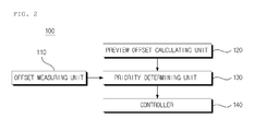
- FIG. 2 is a view illustrating a lateral control apparatus according to an exemplary embodiment of the present invention.
- FIG. 3 is a view illustrating an offset measuring unit illustrated in FIG. 2 .
- FIG. 4 is a view illustrating a preview offset calculating unit illustrated in FIG. 2 .
- FIG. 5 is a view illustrating a preview offset of the other vehicle based on a center of a driving lane.
- FIG. 6 is a flowchart illustrating a lateral control method according to an exemplary embodiment of the present invention.
- FIG. 1 is a view illustrating a lateral offset of the other vehicle based on a center of a driving lane.
- LKAS based on a center C of a driving lane L of an own vehicle 1 , lateral offsets ⁇ 1 , ⁇ 2 , ⁇ 3 , and ⁇ 4 of other vehicles 2 and 3 which drive in adjacent lanes are used to perform lane keeping control of its own vehicle 1 .
- the lateral offsets ⁇ 1 , ⁇ 2 , ⁇ 3 , and ⁇ 4 indicate a lateral departure distance of the other vehicles 2 and 3 from the center C of the driving lane L.
- Such a lateral departure distance of the other vehicles 2 and 3 may be measured by a camera sensor which is built in its own vehicle 1 .
- reference numeral 2 of FIG. 1 denotes other vehicle which precedes its own vehicle 1
- reference numeral 3 of FIG. 1 denotes other vehicle which follows its own vehicle 1 .
- FIG. 2 is a view illustrating a lateral control apparatus according to an exemplary embodiment of the present invention.
- the lateral control apparatus 100 includes an offset measuring unit 110 , a preview offset calculating unit 120 , a priority determining unit 130 , and a controller 140 .
- the lateral control apparatus 100 may be embodied by one or more processors including or corresponding to the offset measuring unit 110 , the preview offset calculating unit 120 , the priority determining unit 130 and the controller 140 , and operable to execute a computer program to perform the operations described herein.
- the offset measuring unit 110 measures lateral offsets ⁇ 1 , ⁇ 2 , ⁇ 3 , and ⁇ 4 of other vehicles 2 and 3 which drive in adjacent lanes based on the center C of the driving lane L of its own vehicle 1 at a current point of time.
- FIG. 3 is a view illustrating an offset measuring unit illustrated in FIG. 2
- FIG. 4 is a view illustrating a preview offset calculating unit illustrated in FIG. 2
- FIG. 5 is a view illustrating a preview offset of the other vehicle based on a center of a driving lane.
- the offset measuring unit 110 includes a first offset measuring unit 111 that measures the lateral offsets ⁇ 1 , ⁇ 2 , and ⁇ 3 of at least one of preceding vehicles 2 which is located in a predetermined distance at a front side of its own vehicle 1 .
- the offset measuring 110 includes a second offset measuring unit 112 that measures a lateral offset ⁇ 4 of at least one following other vehicle 2 located in a predetermined distance at a rear side of its own vehicle 1 .
- the first offset measuring unit 111 may be a front camera sensor 1 a which is built at a front side of its own vehicle 1 and the second offset measuring unit 112 may be a rear camera sensor 1 b which is built at a rear side of its own vehicle 1 .
- the preview offset calculating unit 120 calculates preview offsets ( ⁇ 1 ′ and ⁇ 4 ′ of FIG. 5 ) of the other vehicles 2 and 3 which drive in the adjacent lanes based on the center C of the driving lane L of its own vehicle 1 at a current point of time.
- the preview offsets ( ⁇ 1 ′ and ⁇ 4 ′ of FIG. 5 ) indicates lateral offsets of the other vehicles 2 and 3 which are predicted at a time which a predetermined time has elapsed from the current time.
- the preview offset calculating unit 120 includes a measuring unit 121 and a calculating unit 122 .
- the measuring unit 121 measures longitudinal separation distances x 1 and x 4 and lateral separation distances y 1 and y 4 between its own vehicle 1 and the other vehicles 2 and 3 and measures longitudinal speeds Vx 1 and Vx 4 and lateral speeds Vy 1 and Vy 2 of the other vehicles 2 and 3 .
- the measuring unit 121 may be a front camera sensor 1 a which is built at a front side of its own vehicle 1 and a rear camera sensor 1 b which is built at a rear side of its own vehicle 1 .
- the measuring unit 121 measures a longitudinal separation distance x 1 , a lateral separation distance y 1 , a longitudinal speed Vx 1 , and a lateral speed Vy 1 of the other preceding vehicle 2 from an image of the front side of its own vehicle 1 .
- the measuring unit 121 measures a longitudinal separation distance x 4 , a lateral separation distance y 4 , a longitudinal speed Vx 4 , and a lateral speeds Vy 4 of the other following vehicle 4 from an image of the rear side of its own vehicle 1 .
- the calculating unit 122 predicts and calculates lateral offsets (preview offsets ⁇ 1 ′ and ⁇ 4 ′) of the other vehicles 2 and 3 at a time when a predetermined time has elapsed from the current time based on the longitudinal separation distances x 1 and x 4 , the lateral separation distances y 1 and y 4 , the longitudinal speeds Vx 1 and Vx 4 , and the lateral speeds Vy 1 and Vy measured by the measuring unit 121 .
- the priority determining unit 130 determines a priority from a view point of the lane keeping control based on a difference ⁇ n - ⁇ n ′ between the lateral offset at the current time measured by the offset measuring unit 110 and a preview offset at a future time calculated by the preview offset calculating unit 120 .
- the priority determining unit 130 may assign a top priority to the other vehicle which has the largest difference ⁇ n - ⁇ n ′ between the lateral offset at the current time and a preview offset at a future time among a plurality of other vehicles.
- the lane keeping control is performed based on the lateral offset ⁇ 1 of the other vehicle 2 which precedes its own vehicle 1 .
- the other vehicle to which the top priority is assigned means a vehicle which closely approaches its own vehicle 1 at the highest speed for a predetermined time. Therefore, the other vehicle has the highest risk of crashing with its own vehicle 1 so that the lane keeping control needs to be performed to prevent the crash.
- the corresponding other vehicle is predicted as a vehicle which moves far from its own vehicle 1 so that the vehicle may be removed from a target of the lane keeping control.
- the priority determining 130 determines other vehicle which has a largest difference ⁇ n - ⁇ n ′ between the lateral offset at the current time and the preview offset at a future time as a vehicle having a top priority.
- the present invention is not limited thereto, but a priority of the other vehicles which becomes a target of the lane keeping control may be determined by various methods.
- the controller 140 generates a route for lane keeping control of its own vehicle 1 based on the lateral offset of the other vehicle determined to have a top priority in the priority determining unit 130 . In this case, if a control torque value for steering calculated so as to correspond to the generated route exceeds a predetermined threshold value, a route is regenerated by increasing or decreasing a speed of its own vehicle 1 , in order to prevent a sense of difference in steering caused by the large control torque value.
- FIG. 6 is a flowchart illustrating a lateral control method according to an exemplary embodiment of the present invention.
- the lateral control apparatus 100 measures lateral offsets of at least two other vehicles 2 and 3 at a current time based on the center C of the driving lane (S 100 ).
- a lateral offset of at least one preceding vehicle 2 which is located in a predetermined distance at a front side from the center C of the driving lane
- a lateral offset of at least one following vehicle 3 which is located in a predetermined distance at a rear side from the center C of the driving lane.
- the lateral control apparatus 100 predicts a lateral offset of the other vehicle based on the center C of the driving lane at a time when a predetermined time has elapsed based on the location and a speed of the other vehicles 2 and 3 to calculate a preview offset.
- the lateral control apparatus 100 measures longitudinal separation distances X 1 and X 4 and lateral separation distances y 1 and y 4 between its own vehicle 1 and other vehicles 2 and 3 and also measures longitudinal speeds Vx 1 and Vx 4 and lateral speeds Vy 1 and Vy 4 of the other vehicles 2 and 3 .
- the lateral control apparatus 100 determines a priority of the other vehicles 2 and 3 based on a difference ⁇ n - ⁇ n ′ between the lateral offset and the preview offset (S 300 ).
- a top priority is assigned to a largest difference of the differences ⁇ n - ⁇ n ′ between the lateral offset and the preview offset.
- the lateral control apparatus 100 generates a route for the lane keeping control of its own vehicle 1 based on lateral offsets ⁇ 1 , ⁇ 2 , ⁇ 3 , and ⁇ 4 of the other vehicles 2 and 3 to which the top priority is assigned (S 400 ). In this case, it is determined whether a control torque value corresponding to the generated route exceeds a threshold value (S 410 ). If the control torque value exceeds the threshold value, the lateral control apparatus changes the speed of its own vehicle 1 to regenerate a route (S 420 ).
Landscapes
- Engineering & Computer Science (AREA)
- Physics & Mathematics (AREA)
- Automation & Control Theory (AREA)
- General Physics & Mathematics (AREA)
- Transportation (AREA)
- Mechanical Engineering (AREA)
- Radar, Positioning & Navigation (AREA)
- Remote Sensing (AREA)
- Mathematical Physics (AREA)
- Traffic Control Systems (AREA)
- Steering Control In Accordance With Driving Conditions (AREA)
- Control Of Driving Devices And Active Controlling Of Vehicle (AREA)
Abstract
The present invention provides a lateral control apparatus including: an offset measuring unit that measures current lateral offsets of at least two other vehicles at a current time based on a center of a driving lane; a preview offset calculating unit that predicts a lateral offset of the other vehicle based on the center of the driving lane based on a location and a speed of the other vehicle at a time when a predetermined time has elapsed to calculate a preview offset; a priority determining unit that determines a priority of the other vehicles based on a difference between the lateral offset and the preview offset; and a controller that generates a route for lane keeping control of own vehicle based on the lateral offset of the other vehicle to which a top priority is assigned by the priority determining unit.
Description
This application is a continuation of application Ser. No. 13/847,008 filed on Mar. 19, 2013, which claims the benefit of Korean Application No. 10-2012-0155703 filed on Dec. 28, 2012 in the Korean Intellectual Property Office, the entire disclosures of which are incorporated herein by reference for all purposes.
The present invention relates to a lateral control apparatus of a vehicle and a lateral control method, and particularly, to a lateral control apparatus of a vehicle and a lateral control method that reflects information on other vehicle which drives in an adjacent lane to perform lane keeping control.
In an intelligent vehicle control system, a lane keeping assist system (hereinafter, referred to as “LKAS”) is a necessary system for safety of a driver. This system is generally configured to detect a lane and senses a driving state of a vehicle to perform lane keeping control without departing from the detected lane or issues a warning of the departure of the lane.
A driving lane or adjacent lanes are detected by obtaining an image of a load ahead the vehicle through a camera sensor which is mounted between a windshield and a room mirror of the vehicle and processing the acquired image of the road by a LKAS camera system.
Generally, the LKAS performs the lane keeping control based on the detected lane. However, if the lane keeping control is performed only based on the detected lane, an accident may be caused by an adjacent vehicle or an obstacle. In order to avoid a crash with the adjacent vehicle or the obstacle, there is a problem in that the lane keeping control may be not performed.
If the lane keeping control is performed only based on the lane, a steering torque is determined in accordance with a location of its own vehicle so that the driving may be unstable due to a sense of difference in steering and the leaning of the vehicle.
Therefore, Korean Patent Application Publication No. 10-2011-0054144 suggests a method that sets a driving trace of its own vehicle to be toward an opposite direction of an adjacent vehicle from a center of the lane and generates a steering torque map to be deflected along the deflected driving trace. However, the method has a problem in that if a plurality of vehicles is present ahead in both lanes, the driving trace of its own vehicle cannot be set to be deflected toward the right or left side. Since the method considers a preceding vehicle which is driving in the adjacent lane, the method cannot cope with a vehicle which approaches at a relatively high speed from the rear side.
Since a lateral offset of the adjacent vehicle which is simply and currently measured is used without predicting a proceeding trace of the adjacent vehicle, if a behavior of the vehicle is changed, it is difficult to precisely perform the lane keeping control.
The present invention has been made in an effort to provide a lateral control apparatus of a vehicle and a lateral control method which are capable of controlling a lane of a vehicle in consideration of not only a preceding vehicle of an adjacent lane but also a following vehicle.
The present invention has also been made in an effort to provide a lateral control apparatus of a vehicle and a lateral control method which are capable of minimizing a sense of difference of steering or anxiety which a driver may feel.
An exemplary embodiment of the present invention provides a lateral control apparatus of a vehicle, including: an offset measuring unit that measures current lateral offsets of at least two other vehicles at a current time based on a center of a driving lane; a preview offset calculating unit that predicts a lateral offset of other vehicle based on the center of the driving lane based on a location and a speed of the other vehicle at a time when a predetermined time has elapsed to calculate a preview offset; a priority determining unit that determines a priority of the other vehicle based on a difference between the lateral offset and the preview offset; and a controller that generates a route for lane keeping control of its own vehicle based on the lateral offset of the other vehicle to which a top priority determined by the priority determining unit is assigned.
The offset measuring unit may include a first offset measuring unit that measures an lateral offset of at least one of preceding vehicles which is located in a predetermined distance at a front side based on the center of the driving lane, a second offset measuring unit that measures a lateral offset of at least one following vehicle located in a predetermined distance at a rear side.
The preview offset calculating unit may include a measuring unit that measures a longitudinal separation distance and a lateral separation distance between its own vehicle and the other vehicle and measures a longitudinal speed and a lateral speed of the other vehicle, and a calculating unit that calculates a preview offset of the other vehicle after a predetermined time based on the longitudinal separation distance, the lateral separation distance, the longitudinal speed, and the lateral speed measured by the measuring unit.
The measuring unit may include a front camera sensor that obtains an image of a front side of its own vehicle and a rear camera sensor that obtains an image of a rear side of its own vehicle.
The priority determining unit may assign a priority to one of the other vehicles that has a largest difference between the lateral offset and the preview offset.
If a control torque value corresponding to the generated route exceeds a predetermined threshold, the controller may change a speed of its own vehicle to regenerate a route.
Another exemplary embodiment of the present invention provides a lateral control method including: a) a step of measuring lateral offsets of at least two other vehicles at a current time based on a center of a driving lane; b) a step of predicting a lateral offset of other vehicle based on the center of the driving lane based on a location and a speed of the other vehicle at a time when a predetermined time has elapsed to calculate a preview offset; c) a step of determining a priority of the other vehicles based on a difference between the lateral offset and the preview offset; and d) a step of generating a route to perform lane keeping control of its own vehicle based on the lateral offset of the other vehicle to which a top priority is assigned.
In a) step, a lateral offset of at least one preceding vehicle which is located in a predetermined distance at a front side based on a center of the driving lane may be measured and a lateral offset of at least one following vehicle located in a predetermined distance at a rear side based on the center of the driving lane may be measured.
In b) step, a longitudinal separation distance and a lateral separation distance between its own vehicle and the other vehicle may be measured and a longitudinal speed and a lateral speed of the other vehicle may be measured. A preview offset of the other vehicle after a predetermined time has elapsed may be calculated based on the measured longitudinal separation distance, lateral separation distance, longitudinal speed, and lateral speed.
The longitudinal separation distance, the lateral separation distance, the longitudinal speed, and the lateral speed may be measured through images of the front side and the rear side of its own vehicle.
In c) step, a top priority may be assigned to one of the other vehicles that has a largest difference between the lateral offset and the preview offset.
If a control torque value corresponding to the generated route exceeds a predetermined threshold, a speed of its own vehicle may be changed to regenerate a route.
According to a lateral control apparatus and a control lateral control method of the present invention, a current lateral offset of the other vehicle is compared with a preview lateral offset to perform lane keeping control based on the other vehicle to which a top priority is assigned so that a control range of the LKAS extends to remove a sense of difference in steering and anxiety about driving which a driver may feel.
According to a lateral control apparatus and a lateral control method of the present invention, it is advantageous in that a route is generated to perform lane keeping control by considering not only a preceding vehicle in an adjacent lane but also a following vehicle so as to stably perform lane keeping control.
According to a lateral control apparatus and a lateral control method of the present invention, if a control torque value corresponding to the route generated by comparing the current lateral offset of the other vehicle with the preview lateral offset exceeds a predetermined threshold value, a route is reset. Therefore, it is further advantageous to prevent a sense of difference in steering due to a large steering torque from being avoided.
The foregoing summary is illustrative only and is not intended to be in any way limiting. In addition to the illustrative aspects, embodiments, and features described above, further aspects, embodiments, and features will become apparent by reference to the drawings and the following detailed description.
It should be understood that the appended drawings are not necessarily to scale, presenting a somewhat simplified representation of various features illustrative of the basic principles of the invention. The specific design features of the present invention as disclosed herein, including, for example, specific dimensions, orientations, locations, and shapes will be determined in part by the particular intended application and use environment.
In the figures, reference numbers refer to the same or equivalent parts of the present invention throughout the several figures of the drawing.
Hereinafter, exemplary embodiments of the present invention will be described in detail with reference to the accompanying drawings. In the figures, even though the parts are illustrated in different drawings, it should be understood that like reference numbers refer to the same or equivalent parts of the present invention throughout the several figures of the drawing. Hereinafter, exemplary embodiment of the present invention will be described. However, it should be understood that a technical spirit of the invention is not limited to the specific embodiments, but may be changed or modified by those skilled in the art.
In the meantime, when a direction indicated by an arrow of FIG. 1 is a driving direction, reference numeral 2 of FIG. 1 denotes other vehicle which precedes its own vehicle 1 and reference numeral 3 of FIG. 1 denotes other vehicle which follows its own vehicle 1.
Referring to FIG. 2 , the lateral control apparatus 100 according to an exemplary embodiment of the present invention includes an offset measuring unit 110, a preview offset calculating unit 120, a priority determining unit 130, and a controller 140. The lateral control apparatus 100 may be embodied by one or more processors including or corresponding to the offset measuring unit 110, the preview offset calculating unit 120, the priority determining unit 130 and the controller 140, and operable to execute a computer program to perform the operations described herein.
First, the offset measuring unit 110, as illustrated in FIG. 1 , measures lateral offsets ε1, ε2, ε3, and ε4 of other vehicles 2 and 3 which drive in adjacent lanes based on the center C of the driving lane L of its own vehicle 1 at a current point of time.
In an exemplary embodiment, referring to FIGS. 1 and 3 , the offset measuring unit 110 includes a first offset measuring unit 111 that measures the lateral offsets ε1, ε2, and ε3 of at least one of preceding vehicles 2 which is located in a predetermined distance at a front side of its own vehicle 1. The offset measuring 110 includes a second offset measuring unit 112 that measures a lateral offset ε4 of at least one following other vehicle 2 located in a predetermined distance at a rear side of its own vehicle 1.
Referring to FIG. 5 , the first offset measuring unit 111 may be a front camera sensor 1 a which is built at a front side of its own vehicle 1 and the second offset measuring unit 112 may be a rear camera sensor 1 b which is built at a rear side of its own vehicle 1.
Next, the preview offset calculating unit 120 calculates preview offsets (ε1′ and ε4′ of FIG. 5 ) of the other vehicles 2 and 3 which drive in the adjacent lanes based on the center C of the driving lane L of its own vehicle 1 at a current point of time. Here, the preview offsets (ε1′ and ε4′ of FIG. 5 ) indicates lateral offsets of the other vehicles 2 and 3 which are predicted at a time which a predetermined time has elapsed from the current time. In the exemplary embodiment, the preview offset calculating unit 120 includes a measuring unit 121 and a calculating unit 122.
Referring to FIGS. 4 and 5 , the measuring unit 121 measures longitudinal separation distances x1 and x4 and lateral separation distances y1 and y4 between its own vehicle 1 and the other vehicles 2 and 3 and measures longitudinal speeds Vx1 and Vx4 and lateral speeds Vy1 and Vy2 of the other vehicles 2 and 3. In the exemplary embodiment, when a direction indicated by an arrow of FIG. 5 is a driving direction, the measuring unit 121 may be a front camera sensor 1 a which is built at a front side of its own vehicle 1 and a rear camera sensor 1 b which is built at a rear side of its own vehicle 1. The measuring unit 121 measures a longitudinal separation distance x1, a lateral separation distance y1, a longitudinal speed Vx1, and a lateral speed Vy1 of the other preceding vehicle 2 from an image of the front side of its own vehicle 1. The measuring unit 121 measures a longitudinal separation distance x4, a lateral separation distance y4, a longitudinal speed Vx4, and a lateral speeds Vy4 of the other following vehicle 4 from an image of the rear side of its own vehicle 1.
The calculating unit 122 predicts and calculates lateral offsets (preview offsets ε1′ and ε4′) of the other vehicles 2 and 3 at a time when a predetermined time has elapsed from the current time based on the longitudinal separation distances x1 and x4, the lateral separation distances y1 and y4, the longitudinal speeds Vx1 and Vx4, and the lateral speeds Vy1 and Vy measured by the measuring unit 121.
Next, the priority determining unit 130 determines a priority from a view point of the lane keeping control based on a difference εn-εn′ between the lateral offset at the current time measured by the offset measuring unit 110 and a preview offset at a future time calculated by the preview offset calculating unit 120. In an exemplary embodiment, the priority determining unit 130 may assign a top priority to the other vehicle which has the largest difference εn-εn′ between the lateral offset at the current time and a preview offset at a future time among a plurality of other vehicles. For example, if ε1-ε1′ has the largest value among ε1-ε1′, ε2-ε2′, ε3-ε3′ and ε4-ε4′, as illustrated in FIG. 5 , the lane keeping control is performed based on the lateral offset ε1 of the other vehicle 2 which precedes its own vehicle 1. This is because the other vehicle to which the top priority is assigned means a vehicle which closely approaches its own vehicle 1 at the highest speed for a predetermined time. Therefore, the other vehicle has the highest risk of crashing with its own vehicle 1 so that the lane keeping control needs to be performed to prevent the crash. If the difference εn-εn′ between the lateral offset and the preview offset is a negative value, the corresponding other vehicle is predicted as a vehicle which moves far from its own vehicle 1 so that the vehicle may be removed from a target of the lane keeping control.
In the meantime, in the description of the lateral control apparatus 100 of the exemplary embodiment of the present invention, it is described that the priority determining 130 determines other vehicle which has a largest difference εn-εn′ between the lateral offset at the current time and the preview offset at a future time as a vehicle having a top priority. However, the present invention is not limited thereto, but a priority of the other vehicles which becomes a target of the lane keeping control may be determined by various methods.
The controller 140 generates a route for lane keeping control of its own vehicle 1 based on the lateral offset of the other vehicle determined to have a top priority in the priority determining unit 130. In this case, if a control torque value for steering calculated so as to correspond to the generated route exceeds a predetermined threshold value, a route is regenerated by increasing or decreasing a speed of its own vehicle 1, in order to prevent a sense of difference in steering caused by the large control torque value.
Referring to FIGS. 1 to 6 , the lateral control apparatus 100 according to an exemplary embodiment measures lateral offsets of at least two other vehicles 2 and 3 at a current time based on the center C of the driving lane (S100). In this case, a lateral offset of at least one preceding vehicle 2 which is located in a predetermined distance at a front side from the center C of the driving lane and a lateral offset of at least one following vehicle 3 which is located in a predetermined distance at a rear side from the center C of the driving lane.
Next, the lateral control apparatus 100 predicts a lateral offset of the other vehicle based on the center C of the driving lane at a time when a predetermined time has elapsed based on the location and a speed of the other vehicles 2 and 3 to calculate a preview offset. In this case, the lateral control apparatus 100 measures longitudinal separation distances X1 and X4 and lateral separation distances y1 and y4 between its own vehicle 1 and other vehicles 2 and 3 and also measures longitudinal speeds Vx1 and Vx4 and lateral speeds Vy1 and Vy4 of the other vehicles 2 and 3.
Next, the lateral control apparatus 100 determines a priority of the other vehicles 2 and 3 based on a difference εn-εn′ between the lateral offset and the preview offset (S300). In this case, a top priority is assigned to a largest difference of the differences εn-εn′ between the lateral offset and the preview offset.
Next, the lateral control apparatus 100 generates a route for the lane keeping control of its own vehicle 1 based on lateral offsets ε1, ε2, ε3, and ε4 of the other vehicles 2 and 3 to which the top priority is assigned (S400). In this case, it is determined whether a control torque value corresponding to the generated route exceeds a threshold value (S410). If the control torque value exceeds the threshold value, the lateral control apparatus changes the speed of its own vehicle 1 to regenerate a route (S420).
As described above, the exemplary embodiments have been described and illustrated in the drawings and the specification. The exemplary embodiments were chosen and described in order to explain certain principles of the invention and their practical application, to thereby enable others skilled in the art to make and utilize various exemplary embodiments of the present invention, as well as various alternatives and modifications thereof. As is evident from the foregoing description, certain aspects of the present invention are not limited by the particular details of the examples illustrated herein, and it is therefore contemplated that other modifications and applications, or equivalents thereof, will occur to those skilled in the art. Many changes, modifications, variations and other uses and applications of the present construction will, however, become apparent to those skilled in the art after considering the specification and the accompanying drawings. All such changes, modifications, variations and other uses and applications which do not depart from the spirit and scope of the invention are deemed to be covered by the invention which is limited only by the claims which follow.
Claims (15)
1. A vehicle control system, comprising:
a camera mountable in a second object; and
at least one processor operatively connected to the camera, the at least one processor being configured to
capture from the camera, in real time, image frames from respective images of a first object within a field of view of the camera,
measure a lateral offset and a longitudinal offset of the first object, wherein the first object is disposed in a lane adjacent to a driving lane of the second object at a first time, and wherein the measured lateral offset indicates a distance from the first object to the driving lane at the first time and the measured longitudinal offset indicates a distance from the second object to the first object at the first time,
predict a preview lateral offset and a preview longitudinal offset of the first object based on either one or both of a location and a speed of the first object, wherein the preview lateral offset indicates a predicted distance from the first object to the driving lane at a second time when a predetermined time has elapsed from the first time and the preview longitudinal offset indicates a predicted distance from the second object to the first object at the second time,
determine a priority of the first object with respect to other objects as a function of the measurement and the prediction, wherein the priority is based on a risk of the first object colliding with the second object by entering the driving lane, and
control the second object based on the priority.
2. The vehicle control system of claim 1 , wherein the at least one processor is further configured to determine priorities of additional objects based on:
measurement of a lateral offset and longitudinal offset of the additional objects; and
prediction of either one or both of a preview lateral offset and preview longitudinal offset of the additional objects.
3. The vehicle control system of claim 2 , wherein the control of the second object comprises control of either one or both of a speed and a steering of the second object.
4. A vehicle control system, comprising:
a camera mountable in a vehicle; and
at least one processor operatively connected to the camera, the at least one processor being configured to
capture from the camera, in real time, image frames from respective images of objects within a field of view of the camera,
measure a first position of the objects on a road at a first time, wherein the objects are disposed in a lane of the road adjacent to a driving lane of the vehicle at the first time, and wherein the first position is determined by a longitudinal offset and a lateral offset of the objects obtained by the camera,
predict a second position of the objects on the road at a second time when a predetermined time has elapsed from the first time, wherein the second position is determined by a predicted longitudinal offset and a predicted lateral offset of the objects,
determine priorities of the objects as a function of the measurement and the prediction, wherein the priorities are based on risks of the objects colliding with the vehicle by entering the driving lane, and
control the vehicle based on the priorities.
5. The vehicle control system of claim 4 , wherein the at least one processor is further configured to determine the priorities based on a difference between the lateral offset obtained by the camera and the preview lateral offset.
6. The vehicle control system of claim 5 , wherein the at least one processor is further configured to assign a top priority, among the priorities, to an object, among the objects that has a largest difference between the lateral offset obtained by the camera and the preview lateral offset.
7. The vehicle control system of claim 4 , wherein the control of the vehicle comprises generation of a route within a driving lane and control of a speed of the vehicle based on the priorities.
8. The vehicle control system of claim 7 , wherein the control of the vehicle comprises calculation of a control torque value corresponding to the route.
9. The vehicle control system of claim 4 , wherein:
the control of the vehicle comprises
generation of a first route within a driving lane based on the determination of the priorities, and
in response to a control torque value corresponding to the first route exceeding a predetermined threshold, generation of a second route within the driving lane; and
a control torque value corresponding to the second route is smaller than the predetermined threshold.
10. The vehicle control system of claim 9 , wherein the at least one processor is further configured to generate the second route by changing a speed of the vehicle.
11. A method of controlling a vehicle, the method comprising:
capturing, in real time, from a camera included in a vehicle control system and operatively connected to at least one processor, image frames from respective images of objects within a field of view of the camera;
measuring, using the at least one processor, a first position of the objects on a road at a first time, wherein the objects are disposed in a lane of the road adjacent to a driving lane of the vehicle at the first time, and wherein the first position is determined by a longitudinal offset and a lateral offset of the objects obtained by the camera;
predicting, using the at least one processor, a second position of the objects on the road at a second time when a predetermined time has elapsed from the first time, wherein the second position is determined by a predicted longitudinal offset and a predicted lateral offset of the objects;
determining, using the at least one processor, priorities of the objects as a function of the measurement and the prediction, wherein the priorities are based on risks of the objects colliding with the vehicle by entering the driving lane; and
controlling, using the at least one processor, the vehicle based on the priorities.
12. The method of claim 11 , wherein the controlling of the vehicle comprises generating a route within a driving lane and controlling a speed of the vehicle based on the priorities.
13. The method of claim 12 , wherein the controlling of the vehicle further comprises calculating a control torque value corresponding to the route.
14. The method of claim 11 , wherein the controlling of the vehicle comprises:
generating a first route within a driving lane based on the determining of the priorities; and
in response to a control torque value corresponding to the first route exceeding a predetermined threshold, generating a second route within the driving lane, wherein a control torque value corresponding to the second route is smaller than the predetermined threshold.
15. The method of claim 14 , further comprising generating the second route by changing a speed of the vehicle.
Priority Applications (1)
| Application Number | Priority Date | Filing Date | Title |
|---|---|---|---|
| US14/677,377 US9595197B2 (en) | 2012-12-28 | 2015-04-02 | Lateral control apparatus of vehicle and control method of the same |
Applications Claiming Priority (4)
| Application Number | Priority Date | Filing Date | Title |
|---|---|---|---|
| KR1020120155703A KR101409747B1 (en) | 2012-12-28 | 2012-12-28 | Lateral control apparatus of vehicle and Control method of the same |
| KR10-2012-0155703 | 2012-12-28 | ||
| US13/847,008 US9037373B2 (en) | 2012-12-28 | 2013-03-19 | Lateral control apparatus of vehicle and control method of the same |
| US14/677,377 US9595197B2 (en) | 2012-12-28 | 2015-04-02 | Lateral control apparatus of vehicle and control method of the same |
Related Parent Applications (1)
| Application Number | Title | Priority Date | Filing Date |
|---|---|---|---|
| US13/847,008 Continuation US9037373B2 (en) | 2012-12-28 | 2013-03-19 | Lateral control apparatus of vehicle and control method of the same |
Publications (2)
| Publication Number | Publication Date |
|---|---|
| US20150213719A1 US20150213719A1 (en) | 2015-07-30 |
| US9595197B2 true US9595197B2 (en) | 2017-03-14 |
Family
ID=51018135
Family Applications (2)
| Application Number | Title | Priority Date | Filing Date |
|---|---|---|---|
| US13/847,008 Active US9037373B2 (en) | 2012-12-28 | 2013-03-19 | Lateral control apparatus of vehicle and control method of the same |
| US14/677,377 Active 2033-03-24 US9595197B2 (en) | 2012-12-28 | 2015-04-02 | Lateral control apparatus of vehicle and control method of the same |
Family Applications Before (1)
| Application Number | Title | Priority Date | Filing Date |
|---|---|---|---|
| US13/847,008 Active US9037373B2 (en) | 2012-12-28 | 2013-03-19 | Lateral control apparatus of vehicle and control method of the same |
Country Status (3)
| Country | Link |
|---|---|
| US (2) | US9037373B2 (en) |
| KR (1) | KR101409747B1 (en) |
| CN (1) | CN103909927B (en) |
Cited By (6)
| Publication number | Priority date | Publication date | Assignee | Title |
|---|---|---|---|---|
| US20230015357A1 (en) * | 2021-07-13 | 2023-01-19 | Canoo Technologies Inc. | System and method in the prediction of target vehicle behavior based on image frame and normalization |
| US11840147B2 (en) | 2021-07-13 | 2023-12-12 | Canoo Technologies Inc. | System and method in data-driven vehicle dynamic modeling for path-planning and control |
| US11845428B2 (en) | 2021-07-13 | 2023-12-19 | Canoo Technologies Inc. | System and method for lane departure warning with ego motion and vision |
| US11891060B2 (en) | 2021-07-13 | 2024-02-06 | Canoo Technologies Inc. | System and method in lane departure warning with full nonlinear kinematics and curvature |
| US11891059B2 (en) | 2021-07-13 | 2024-02-06 | Canoo Technologies Inc. | System and methods of integrating vehicle kinematics and dynamics for lateral control feature at autonomous driving |
| US12017661B2 (en) | 2021-07-13 | 2024-06-25 | Canoo Technologies Inc. | System and method in vehicle path prediction based on full nonlinear kinematics |
Families Citing this family (20)
| Publication number | Priority date | Publication date | Assignee | Title |
|---|---|---|---|---|
| DE102013201796A1 (en) * | 2013-02-05 | 2014-08-07 | Robert Bosch Gmbh | Method for providing a driving corridor for a vehicle and driver assistance system |
| JP2016018295A (en) * | 2014-07-07 | 2016-02-01 | 日立オートモティブシステムズ株式会社 | Information processing system |
| CN104260723B (en) * | 2014-09-29 | 2018-03-06 | 长安大学 | A kind of front vehicle motion state tracking prediction meanss and Forecasting Methodology |
| KR20160066297A (en) * | 2014-12-02 | 2016-06-10 | 현대모비스 주식회사 | Apparatus and method for controlling start-up for lane keeping assist system |
| WO2016127307A1 (en) * | 2015-02-10 | 2016-08-18 | Harman International Industries, Incorporated | Vehicular communication |
| KR101980547B1 (en) * | 2015-08-19 | 2019-05-21 | 엘지전자 주식회사 | Driver assistance apparatus for vehicle and Vehicle |
| KR20170071120A (en) * | 2015-12-15 | 2017-06-23 | 현대자동차주식회사 | Lkas system, vehicle including the same, and controlling method for lkas |
| JP2017114155A (en) * | 2015-12-21 | 2017-06-29 | 三菱自動車工業株式会社 | Drive support device |
| KR101860626B1 (en) * | 2016-01-07 | 2018-07-02 | 엘지전자 주식회사 | Driver Assistance Apparatus and Vehicle Having The Same |
| JP6575479B2 (en) * | 2016-10-13 | 2019-09-18 | トヨタ自動車株式会社 | Lane maintenance support device |
| JP6592423B2 (en) * | 2016-11-25 | 2019-10-16 | 株式会社デンソー | Vehicle control device |
| CN106627582B (en) * | 2016-12-09 | 2019-01-22 | 重庆长安汽车股份有限公司 | Bicycle road automatic Pilot surmounts the path planning system and method for fellow road-users |
| US10353393B2 (en) * | 2016-12-29 | 2019-07-16 | Baidu Usa Llc | Method and system for improving stability of autonomous driving vehicles |
| US10403145B2 (en) * | 2017-01-19 | 2019-09-03 | Ford Global Technologies, Llc | Collison mitigation and avoidance |
| JP7238670B2 (en) * | 2019-07-23 | 2023-03-14 | トヨタ自動車株式会社 | image display device |
| CN111806437B (en) * | 2020-09-10 | 2021-01-15 | 中汽研(天津)汽车工程研究院有限公司 | Method, device, equipment and storage medium for determining aiming point of automatic driving automobile |
| CN112590802B (en) * | 2020-12-04 | 2022-12-20 | 英博超算(南京)科技有限公司 | Vehicle driving control method, device, vehicle and computer readable storage medium |
| CN112622899B (en) * | 2021-01-18 | 2022-04-01 | 中国重汽集团济南动力有限公司 | Vehicle lane keeping method and system based on preview area control |
| JP7191179B1 (en) * | 2021-10-27 | 2022-12-16 | 三菱電機株式会社 | VEHICLE CONTROL DEVICE, VEHICLE CONTROL SYSTEM, VEHICLE CONTROL METHOD AND VEHICLE CONTROL PROGRAM |
| CN115083190B (en) * | 2022-06-17 | 2023-04-25 | 东风汽车集团股份有限公司 | Automatic driving system and method for multi-lane traffic intersection |
Citations (23)
| Publication number | Priority date | Publication date | Assignee | Title |
|---|---|---|---|---|
| US5642093A (en) | 1995-01-27 | 1997-06-24 | Fuji Jukogyo Kabushiki Kaisha | Warning system for vehicle |
| JP2000025631A (en) | 1998-07-10 | 2000-01-25 | Nissan Motor Co Ltd | Lane keep system |
| US6230093B1 (en) | 1997-05-31 | 2001-05-08 | Robert Bosch Gmbh | Method and device for determining the probable path to be covered by a vehicle |
| US20030062769A1 (en) | 2001-09-28 | 2003-04-03 | Nissan Motor Co., Ltd. | Lane-keep control system for vehicle |
| US6571176B1 (en) * | 1999-06-16 | 2003-05-27 | Honda Giken Kogyo Kabushiki Kaisha | Vehicle travel safety device |
| US6653935B1 (en) | 1999-11-12 | 2003-11-25 | Robert Bosch Gmbh | Method for evaluating objects in the path of a vehicle |
| JP2005056025A (en) | 2003-07-31 | 2005-03-03 | Nissan Motor Co Ltd | Lane deviation prevention system |
| US20050228588A1 (en) * | 2002-04-23 | 2005-10-13 | Goetz Braeuchle | Lateral guidance assistance for motor vehicles |
| US20060047388A1 (en) | 2004-09-01 | 2006-03-02 | Mazda Motor Corporation | Lane deviation warning device of vehicle |
| US20060095193A1 (en) * | 2004-10-29 | 2006-05-04 | Nissan Motor Co., Ltd. | Vehicle operation support apparatus |
| US7046171B2 (en) | 2003-05-12 | 2006-05-16 | Nissan Motor Co., Ltd. | Vehicle surrounding area image system |
| JP2008070998A (en) | 2006-09-13 | 2008-03-27 | Hitachi Ltd | Vehicle surroundings information display unit |
| JP2009234560A (en) | 2008-03-04 | 2009-10-15 | Nissan Motor Co Ltd | Lane keeping support device and lane keeping support method |
| US7640108B2 (en) | 1999-06-25 | 2009-12-29 | Fujitsu Ten Limited | Vehicle drive assist system |
| KR20100058066A (en) | 2008-11-24 | 2010-06-03 | 현대자동차주식회사 | A lane maintenance control system using a variable determination reference |
| US20100228420A1 (en) | 2009-03-06 | 2010-09-09 | Gm Global Technology Operations, Inc. | Model based predictive control for automated lane centering/changing control systems |
| JP2010271750A (en) | 2009-05-19 | 2010-12-02 | Suzuki Motor Corp | Vehicle traveling control device |
| US20110093177A1 (en) * | 2009-10-21 | 2011-04-21 | Horn Berthold K P | Method and Apparatus for Reducing Motor Vehicle Traffic Flow Instabilities and Increasing Vehicle Throughput |
| KR20110054144A (en) | 2009-11-17 | 2011-05-25 | 주식회사 만도 | Method and system for controlling lane keeping |
| JP2011242887A (en) | 2010-05-14 | 2011-12-01 | Toyota Motor Corp | Collision prediction apparatus |
| US8473144B1 (en) | 2012-10-30 | 2013-06-25 | Google Inc. | Controlling vehicle lateral lane positioning |
| US8494716B1 (en) | 2012-06-04 | 2013-07-23 | GM Global Technology Operations LLC | Lane keeping system using rear camera |
| US8600657B2 (en) | 2008-09-19 | 2013-12-03 | Hitachi Automotive Systems, Ltd. | Vehicle control apparatus |
Family Cites Families (6)
| Publication number | Priority date | Publication date | Assignee | Title |
|---|---|---|---|---|
| JP3982503B2 (en) * | 2004-01-21 | 2007-09-26 | 日産自動車株式会社 | Vehicle travel control device |
| DE102006047634A1 (en) * | 2006-10-09 | 2008-04-10 | Robert Bosch Gmbh | Method for detecting an environment of a vehicle |
| CN101135558B (en) * | 2007-09-28 | 2010-09-01 | 上海中科深江电动车辆有限公司 | Vehicle anti-collision early warning method and apparatus based on machine vision |
| US9090263B2 (en) * | 2010-07-20 | 2015-07-28 | GM Global Technology Operations LLC | Lane fusion system using forward-view and rear-view cameras |
| US20120022739A1 (en) * | 2010-07-20 | 2012-01-26 | Gm Global Technology Operations, Inc. | Robust vehicular lateral control with front and rear cameras |
| JP2012073925A (en) * | 2010-09-29 | 2012-04-12 | Fuji Heavy Ind Ltd | Driving support device for vehicle |
-
2012
- 2012-12-28 KR KR1020120155703A patent/KR101409747B1/en active IP Right Grant
-
2013
- 2013-01-29 CN CN201310033303.9A patent/CN103909927B/en active Active
- 2013-03-19 US US13/847,008 patent/US9037373B2/en active Active
-
2015
- 2015-04-02 US US14/677,377 patent/US9595197B2/en active Active
Patent Citations (23)
| Publication number | Priority date | Publication date | Assignee | Title |
|---|---|---|---|---|
| US5642093A (en) | 1995-01-27 | 1997-06-24 | Fuji Jukogyo Kabushiki Kaisha | Warning system for vehicle |
| US6230093B1 (en) | 1997-05-31 | 2001-05-08 | Robert Bosch Gmbh | Method and device for determining the probable path to be covered by a vehicle |
| JP2000025631A (en) | 1998-07-10 | 2000-01-25 | Nissan Motor Co Ltd | Lane keep system |
| US6571176B1 (en) * | 1999-06-16 | 2003-05-27 | Honda Giken Kogyo Kabushiki Kaisha | Vehicle travel safety device |
| US7640108B2 (en) | 1999-06-25 | 2009-12-29 | Fujitsu Ten Limited | Vehicle drive assist system |
| US6653935B1 (en) | 1999-11-12 | 2003-11-25 | Robert Bosch Gmbh | Method for evaluating objects in the path of a vehicle |
| US20030062769A1 (en) | 2001-09-28 | 2003-04-03 | Nissan Motor Co., Ltd. | Lane-keep control system for vehicle |
| US20050228588A1 (en) * | 2002-04-23 | 2005-10-13 | Goetz Braeuchle | Lateral guidance assistance for motor vehicles |
| US7046171B2 (en) | 2003-05-12 | 2006-05-16 | Nissan Motor Co., Ltd. | Vehicle surrounding area image system |
| JP2005056025A (en) | 2003-07-31 | 2005-03-03 | Nissan Motor Co Ltd | Lane deviation prevention system |
| US20060047388A1 (en) | 2004-09-01 | 2006-03-02 | Mazda Motor Corporation | Lane deviation warning device of vehicle |
| US20060095193A1 (en) * | 2004-10-29 | 2006-05-04 | Nissan Motor Co., Ltd. | Vehicle operation support apparatus |
| JP2008070998A (en) | 2006-09-13 | 2008-03-27 | Hitachi Ltd | Vehicle surroundings information display unit |
| JP2009234560A (en) | 2008-03-04 | 2009-10-15 | Nissan Motor Co Ltd | Lane keeping support device and lane keeping support method |
| US8600657B2 (en) | 2008-09-19 | 2013-12-03 | Hitachi Automotive Systems, Ltd. | Vehicle control apparatus |
| KR20100058066A (en) | 2008-11-24 | 2010-06-03 | 현대자동차주식회사 | A lane maintenance control system using a variable determination reference |
| US20100228420A1 (en) | 2009-03-06 | 2010-09-09 | Gm Global Technology Operations, Inc. | Model based predictive control for automated lane centering/changing control systems |
| JP2010271750A (en) | 2009-05-19 | 2010-12-02 | Suzuki Motor Corp | Vehicle traveling control device |
| US20110093177A1 (en) * | 2009-10-21 | 2011-04-21 | Horn Berthold K P | Method and Apparatus for Reducing Motor Vehicle Traffic Flow Instabilities and Increasing Vehicle Throughput |
| KR20110054144A (en) | 2009-11-17 | 2011-05-25 | 주식회사 만도 | Method and system for controlling lane keeping |
| JP2011242887A (en) | 2010-05-14 | 2011-12-01 | Toyota Motor Corp | Collision prediction apparatus |
| US8494716B1 (en) | 2012-06-04 | 2013-07-23 | GM Global Technology Operations LLC | Lane keeping system using rear camera |
| US8473144B1 (en) | 2012-10-30 | 2013-06-25 | Google Inc. | Controlling vehicle lateral lane positioning |
Non-Patent Citations (1)
| Title |
|---|
| Korean Office Action Issued on Mar. 19, 2014, in counterpart Korean Application No. 10-2012-0155703 (5 pages, in Korean). |
Cited By (7)
| Publication number | Priority date | Publication date | Assignee | Title |
|---|---|---|---|---|
| US20230015357A1 (en) * | 2021-07-13 | 2023-01-19 | Canoo Technologies Inc. | System and method in the prediction of target vehicle behavior based on image frame and normalization |
| US11840147B2 (en) | 2021-07-13 | 2023-12-12 | Canoo Technologies Inc. | System and method in data-driven vehicle dynamic modeling for path-planning and control |
| US11845428B2 (en) | 2021-07-13 | 2023-12-19 | Canoo Technologies Inc. | System and method for lane departure warning with ego motion and vision |
| US11891060B2 (en) | 2021-07-13 | 2024-02-06 | Canoo Technologies Inc. | System and method in lane departure warning with full nonlinear kinematics and curvature |
| US11891059B2 (en) | 2021-07-13 | 2024-02-06 | Canoo Technologies Inc. | System and methods of integrating vehicle kinematics and dynamics for lateral control feature at autonomous driving |
| US11908200B2 (en) * | 2021-07-13 | 2024-02-20 | Canoo Technologies Inc. | System and method in the prediction of target vehicle behavior based on image frame and normalization |
| US12017661B2 (en) | 2021-07-13 | 2024-06-25 | Canoo Technologies Inc. | System and method in vehicle path prediction based on full nonlinear kinematics |
Also Published As
| Publication number | Publication date |
|---|---|
| CN103909927B (en) | 2017-10-24 |
| US20140188360A1 (en) | 2014-07-03 |
| US20150213719A1 (en) | 2015-07-30 |
| CN103909927A (en) | 2014-07-09 |
| KR101409747B1 (en) | 2014-07-02 |
| US9037373B2 (en) | 2015-05-19 |
Similar Documents
| Publication | Publication Date | Title |
|---|---|---|
| US9595197B2 (en) | Lateral control apparatus of vehicle and control method of the same | |
| US11738744B2 (en) | Driving support apparatus | |
| CN110352450B (en) | Driving assistance method and driving assistance device | |
| JP6005055B2 (en) | Method for continuously calculating, inspecting and / or adapting a parking trajectory in a vehicle parking assist system, a computer program and a parking assist system | |
| JP5167051B2 (en) | Vehicle driving support device | |
| JP6397934B2 (en) | Travel control device | |
| US8669854B2 (en) | Determination and signalling to a driver of a motor vehicle of a potential collision of the motor vehicle with an obstacle | |
| US9196163B2 (en) | Driving support apparatus and driving support method | |
| JP5938569B2 (en) | Advanced driver support system considering azimuth information and operation method thereof | |
| KR100854766B1 (en) | Method for detecting of parking area by using range sensor | |
| US20140129084A1 (en) | Control apparatus of vehicle for changing lane and control method of the same | |
| JP2013225295A5 (en) | ||
| US11180081B2 (en) | Rear-side alarm device and rear-side alarm method thereof | |
| JP2005209019A (en) | Apparatus, method and program for obstacle detection | |
| JP4896482B2 (en) | Collision determination device | |
| CN106608259B (en) | Automatic emergency braking device and method | |
| JP2013224094A (en) | Vehicle traveling control device | |
| JP5482323B2 (en) | Driving support device and program | |
| JP4850963B1 (en) | Vehicle driving support device | |
| KR102545582B1 (en) | System for avoiding collision in crossroad and method for control thereof | |
| CN113424242B (en) | Information processing apparatus, computer-readable recording medium, and information processing method | |
| KR20200140979A (en) | Method, Apparatus for controlling vehicle, and system including it | |
| JP6330868B2 (en) | Vehicle control device | |
| JP2009181310A (en) | Road parameter estimation device | |
| JP6295868B2 (en) | Vehicle display device |
Legal Events
| Date | Code | Title | Description |
|---|---|---|---|
| FEPP | Fee payment procedure |
Free format text: PAYOR NUMBER ASSIGNED (ORIGINAL EVENT CODE: ASPN); ENTITY STATUS OF PATENT OWNER: LARGE ENTITY |
|
| STCF | Information on status: patent grant |
Free format text: PATENTED CASE |
|
| MAFP | Maintenance fee payment |
Free format text: PAYMENT OF MAINTENANCE FEE, 4TH YEAR, LARGE ENTITY (ORIGINAL EVENT CODE: M1551); ENTITY STATUS OF PATENT OWNER: LARGE ENTITY Year of fee payment: 4 |
|
| MAFP | Maintenance fee payment |
Free format text: PAYMENT OF MAINTENANCE FEE, 8TH YEAR, LARGE ENTITY (ORIGINAL EVENT CODE: M1552); ENTITY STATUS OF PATENT OWNER: LARGE ENTITY Year of fee payment: 8 |