JP2017114155A - Drive support device - Google Patents
Drive support device Download PDFInfo
- Publication number
- JP2017114155A JP2017114155A JP2015248542A JP2015248542A JP2017114155A JP 2017114155 A JP2017114155 A JP 2017114155A JP 2015248542 A JP2015248542 A JP 2015248542A JP 2015248542 A JP2015248542 A JP 2015248542A JP 2017114155 A JP2017114155 A JP 2017114155A
- Authority
- JP
- Japan
- Prior art keywords
- vehicle
- lane
- approach
- detection
- size
- Prior art date
- Legal status (The legal status is an assumption and is not a legal conclusion. Google has not performed a legal analysis and makes no representation as to the accuracy of the status listed.)
- Pending
Links
- 238000001514 detection method Methods 0.000 claims abstract description 144
- 238000013459 approach Methods 0.000 claims abstract description 94
- 230000001629 suppression Effects 0.000 claims abstract description 44
- 238000004891 communication Methods 0.000 claims description 22
- 230000007423 decrease Effects 0.000 claims description 2
- 238000010586 diagram Methods 0.000 description 5
- 238000000034 method Methods 0.000 description 5
- 230000002265 prevention Effects 0.000 description 3
- 230000003247 decreasing effect Effects 0.000 description 2
- 238000010191 image analysis Methods 0.000 description 2
- 238000003384 imaging method Methods 0.000 description 2
- 230000000452 restraining effect Effects 0.000 description 2
- 240000001973 Ficus microcarpa Species 0.000 description 1
- 238000005259 measurement Methods 0.000 description 1
- 230000003340 mental effect Effects 0.000 description 1
- 238000012545 processing Methods 0.000 description 1
Images


Classifications
-
- G—PHYSICS
- G08—SIGNALLING
- G08G—TRAFFIC CONTROL SYSTEMS
- G08G1/00—Traffic control systems for road vehicles
- G08G1/16—Anti-collision systems
- G08G1/167—Driving aids for lane monitoring, lane changing, e.g. blind spot detection
-
- B—PERFORMING OPERATIONS; TRANSPORTING
- B62—LAND VEHICLES FOR TRAVELLING OTHERWISE THAN ON RAILS
- B62D—MOTOR VEHICLES; TRAILERS
- B62D15/00—Steering not otherwise provided for
- B62D15/02—Steering position indicators ; Steering position determination; Steering aids
- B62D15/025—Active steering aids, e.g. helping the driver by actively influencing the steering system after environment evaluation
- B62D15/0265—Automatic obstacle avoidance by steering
-
- B—PERFORMING OPERATIONS; TRANSPORTING
- B60—VEHICLES IN GENERAL
- B60Q—ARRANGEMENT OF SIGNALLING OR LIGHTING DEVICES, THE MOUNTING OR SUPPORTING THEREOF OR CIRCUITS THEREFOR, FOR VEHICLES IN GENERAL
- B60Q3/00—Arrangement of lighting devices for vehicle interiors; Lighting devices specially adapted for vehicle interiors
-
- B—PERFORMING OPERATIONS; TRANSPORTING
- B60—VEHICLES IN GENERAL
- B60Q—ARRANGEMENT OF SIGNALLING OR LIGHTING DEVICES, THE MOUNTING OR SUPPORTING THEREOF OR CIRCUITS THEREFOR, FOR VEHICLES IN GENERAL
- B60Q5/00—Arrangement or adaptation of acoustic signal devices
- B60Q5/005—Arrangement or adaptation of acoustic signal devices automatically actuated
- B60Q5/006—Arrangement or adaptation of acoustic signal devices automatically actuated indicating risk of collision between vehicles or with pedestrians
-
- B—PERFORMING OPERATIONS; TRANSPORTING
- B60—VEHICLES IN GENERAL
- B60Q—ARRANGEMENT OF SIGNALLING OR LIGHTING DEVICES, THE MOUNTING OR SUPPORTING THEREOF OR CIRCUITS THEREFOR, FOR VEHICLES IN GENERAL
- B60Q9/00—Arrangement or adaptation of signal devices not provided for in one of main groups B60Q1/00 - B60Q7/00, e.g. haptic signalling
- B60Q9/008—Arrangement or adaptation of signal devices not provided for in one of main groups B60Q1/00 - B60Q7/00, e.g. haptic signalling for anti-collision purposes
-
- B—PERFORMING OPERATIONS; TRANSPORTING
- B60—VEHICLES IN GENERAL
- B60R—VEHICLES, VEHICLE FITTINGS, OR VEHICLE PARTS, NOT OTHERWISE PROVIDED FOR
- B60R11/00—Arrangements for holding or mounting articles, not otherwise provided for
- B60R11/04—Mounting of cameras operative during drive; Arrangement of controls thereof relative to the vehicle
-
- B—PERFORMING OPERATIONS; TRANSPORTING
- B60—VEHICLES IN GENERAL
- B60W—CONJOINT CONTROL OF VEHICLE SUB-UNITS OF DIFFERENT TYPE OR DIFFERENT FUNCTION; CONTROL SYSTEMS SPECIALLY ADAPTED FOR HYBRID VEHICLES; ROAD VEHICLE DRIVE CONTROL SYSTEMS FOR PURPOSES NOT RELATED TO THE CONTROL OF A PARTICULAR SUB-UNIT
- B60W30/00—Purposes of road vehicle drive control systems not related to the control of a particular sub-unit, e.g. of systems using conjoint control of vehicle sub-units
- B60W30/10—Path keeping
- B60W30/12—Lane keeping
-
- B—PERFORMING OPERATIONS; TRANSPORTING
- B60—VEHICLES IN GENERAL
- B60W—CONJOINT CONTROL OF VEHICLE SUB-UNITS OF DIFFERENT TYPE OR DIFFERENT FUNCTION; CONTROL SYSTEMS SPECIALLY ADAPTED FOR HYBRID VEHICLES; ROAD VEHICLE DRIVE CONTROL SYSTEMS FOR PURPOSES NOT RELATED TO THE CONTROL OF A PARTICULAR SUB-UNIT
- B60W30/00—Purposes of road vehicle drive control systems not related to the control of a particular sub-unit, e.g. of systems using conjoint control of vehicle sub-units
- B60W30/18—Propelling the vehicle
- B60W30/18009—Propelling the vehicle related to particular drive situations
- B60W30/18163—Lane change; Overtaking manoeuvres
-
- B—PERFORMING OPERATIONS; TRANSPORTING
- B60—VEHICLES IN GENERAL
- B60W—CONJOINT CONTROL OF VEHICLE SUB-UNITS OF DIFFERENT TYPE OR DIFFERENT FUNCTION; CONTROL SYSTEMS SPECIALLY ADAPTED FOR HYBRID VEHICLES; ROAD VEHICLE DRIVE CONTROL SYSTEMS FOR PURPOSES NOT RELATED TO THE CONTROL OF A PARTICULAR SUB-UNIT
- B60W50/00—Details of control systems for road vehicle drive control not related to the control of a particular sub-unit, e.g. process diagnostic or vehicle driver interfaces
- B60W50/08—Interaction between the driver and the control system
- B60W50/14—Means for informing the driver, warning the driver or prompting a driver intervention
-
- G—PHYSICS
- G01—MEASURING; TESTING
- G01S—RADIO DIRECTION-FINDING; RADIO NAVIGATION; DETERMINING DISTANCE OR VELOCITY BY USE OF RADIO WAVES; LOCATING OR PRESENCE-DETECTING BY USE OF THE REFLECTION OR RERADIATION OF RADIO WAVES; ANALOGOUS ARRANGEMENTS USING OTHER WAVES
- G01S19/00—Satellite radio beacon positioning systems; Determining position, velocity or attitude using signals transmitted by such systems
- G01S19/01—Satellite radio beacon positioning systems transmitting time-stamped messages, e.g. GPS [Global Positioning System], GLONASS [Global Orbiting Navigation Satellite System] or GALILEO
- G01S19/13—Receivers
- G01S19/14—Receivers specially adapted for specific applications
-
- B—PERFORMING OPERATIONS; TRANSPORTING
- B60—VEHICLES IN GENERAL
- B60W—CONJOINT CONTROL OF VEHICLE SUB-UNITS OF DIFFERENT TYPE OR DIFFERENT FUNCTION; CONTROL SYSTEMS SPECIALLY ADAPTED FOR HYBRID VEHICLES; ROAD VEHICLE DRIVE CONTROL SYSTEMS FOR PURPOSES NOT RELATED TO THE CONTROL OF A PARTICULAR SUB-UNIT
- B60W2420/00—Indexing codes relating to the type of sensors based on the principle of their operation
- B60W2420/40—Photo, light or radio wave sensitive means, e.g. infrared sensors
- B60W2420/403—Image sensing, e.g. optical camera
-
- B—PERFORMING OPERATIONS; TRANSPORTING
- B60—VEHICLES IN GENERAL
- B60W—CONJOINT CONTROL OF VEHICLE SUB-UNITS OF DIFFERENT TYPE OR DIFFERENT FUNCTION; CONTROL SYSTEMS SPECIALLY ADAPTED FOR HYBRID VEHICLES; ROAD VEHICLE DRIVE CONTROL SYSTEMS FOR PURPOSES NOT RELATED TO THE CONTROL OF A PARTICULAR SUB-UNIT
- B60W2540/00—Input parameters relating to occupants
- B60W2540/20—Direction indicator values
-
- B—PERFORMING OPERATIONS; TRANSPORTING
- B60—VEHICLES IN GENERAL
- B60W—CONJOINT CONTROL OF VEHICLE SUB-UNITS OF DIFFERENT TYPE OR DIFFERENT FUNCTION; CONTROL SYSTEMS SPECIALLY ADAPTED FOR HYBRID VEHICLES; ROAD VEHICLE DRIVE CONTROL SYSTEMS FOR PURPOSES NOT RELATED TO THE CONTROL OF A PARTICULAR SUB-UNIT
- B60W2555/00—Input parameters relating to exterior conditions, not covered by groups B60W2552/00, B60W2554/00
- B60W2555/20—Ambient conditions, e.g. wind or rain
-
- B—PERFORMING OPERATIONS; TRANSPORTING
- B60—VEHICLES IN GENERAL
- B60W—CONJOINT CONTROL OF VEHICLE SUB-UNITS OF DIFFERENT TYPE OR DIFFERENT FUNCTION; CONTROL SYSTEMS SPECIALLY ADAPTED FOR HYBRID VEHICLES; ROAD VEHICLE DRIVE CONTROL SYSTEMS FOR PURPOSES NOT RELATED TO THE CONTROL OF A PARTICULAR SUB-UNIT
- B60W2556/00—Input parameters relating to data
- B60W2556/45—External transmission of data to or from the vehicle
- B60W2556/50—External transmission of data to or from the vehicle of positioning data, e.g. GPS [Global Positioning System] data
-
- B—PERFORMING OPERATIONS; TRANSPORTING
- B60—VEHICLES IN GENERAL
- B60W—CONJOINT CONTROL OF VEHICLE SUB-UNITS OF DIFFERENT TYPE OR DIFFERENT FUNCTION; CONTROL SYSTEMS SPECIALLY ADAPTED FOR HYBRID VEHICLES; ROAD VEHICLE DRIVE CONTROL SYSTEMS FOR PURPOSES NOT RELATED TO THE CONTROL OF A PARTICULAR SUB-UNIT
- B60W2556/00—Input parameters relating to data
- B60W2556/45—External transmission of data to or from the vehicle
- B60W2556/65—Data transmitted between vehicles
-
- B—PERFORMING OPERATIONS; TRANSPORTING
- B60—VEHICLES IN GENERAL
- B60W—CONJOINT CONTROL OF VEHICLE SUB-UNITS OF DIFFERENT TYPE OR DIFFERENT FUNCTION; CONTROL SYSTEMS SPECIALLY ADAPTED FOR HYBRID VEHICLES; ROAD VEHICLE DRIVE CONTROL SYSTEMS FOR PURPOSES NOT RELATED TO THE CONTROL OF A PARTICULAR SUB-UNIT
- B60W2710/00—Output or target parameters relating to a particular sub-units
- B60W2710/20—Steering systems
- B60W2710/207—Steering angle of wheels
Landscapes
- Engineering & Computer Science (AREA)
- Mechanical Engineering (AREA)
- Automation & Control Theory (AREA)
- Transportation (AREA)
- Physics & Mathematics (AREA)
- Human Computer Interaction (AREA)
- General Physics & Mathematics (AREA)
- Remote Sensing (AREA)
- Radar, Positioning & Navigation (AREA)
- Acoustics & Sound (AREA)
- Computer Networks & Wireless Communication (AREA)
- Chemical & Material Sciences (AREA)
- Combustion & Propulsion (AREA)
- Traffic Control Systems (AREA)
- Control Of Driving Devices And Active Controlling Of Vehicle (AREA)
Abstract
Description
本発明は、自車の後側方を走行する他車の前方に車線を変更する場合に運転者へ警報などを報知する運転支援装置に関する。 The present invention relates to a driving support device that notifies a driver of an alarm or the like when a lane is changed in front of another vehicle traveling behind the host vehicle.
片側2車線の車両通行帯の第1の車線を自車が走行し、自車よりも後方の第2の車線を他車が走行している状況において車線変更を行う場合、他車を検出して警報等を報知する運転支援装置がある。この運転支援装置として、後側方を並走する他車が死角となる位置にある場合にこれを検出する後側方死角警報(Blind Spot Warning:BSW)と、追越車接近警報(Lane Change Assist:LCA)とが知られている。 When the vehicle is traveling in the first lane of the two-lane vehicle lane and the other vehicle is traveling in the second lane behind the vehicle, the other vehicle is detected. There is a driving support device that notifies a warning or the like. As this driving support device, a rear side blind spot warning (BSW) that detects when another vehicle running parallel to the rear side is in a blind spot position, and a passing vehicle approach warning (Lane Change) Assist: LCA) is known.
特許文献1に記載された車両運転支援装置は、自車の後側方に存在する他車に対する自車の接近防止を支援する接近防止制御を行う。このとき自車の運転者が他車を認識している状態であっても接近防止制御が開始される条件を満たすことで他車に対する接近を防止するように自車が制御されると、運転者に煩わしさを感じさせてしまう。そこで、特許文献1の車両運転支援装置では、自車と並走する他車を追い抜いている状態もしくは追い抜いた状態になると予測される状態の少なくとも一方の状態である追い抜き状態を検出し、この追い抜き状態であると判定すると、接近防止制御を抑制している。
The vehicle driving support device described in
ところで、自車よりも大きな車両が接近してくると、運転者によっては威圧感を覚えるため、なるべく車間を空けて走行したい。後側方から接近してくる他車を検出する検出範囲が所定の大きさに設定されていると、大きな車両の前にも他の車両の場合と同じように車線変更できてしまう。意図せずに車線変更してしまうことも生じるため、運転者にとって精神的なストレスになる。また、車体の大きな車両の重量は大きく、制動距離も長い。したがって、大きな車両に対して安全な車間距離を取るためには、自車と同じ程度の大きさの車両に比べて車間距離を大きく設定する必要があるが、特許文献1にはその点について示唆する記載が無い。
By the way, when a vehicle larger than the host vehicle approaches, some drivers feel intimidating, so they want to travel with as much space as possible. If the detection range for detecting other vehicles approaching from the rear side is set to a predetermined size, the lane can be changed in front of a large vehicle as in the case of other vehicles. It may cause mental stress for the driver because the lane may be changed unintentionally. In addition, a vehicle with a large vehicle body is heavy and has a long braking distance. Therefore, in order to obtain a safe inter-vehicle distance for a large vehicle, it is necessary to set the inter-vehicle distance larger than that of a vehicle having the same size as the own vehicle. However,
そこで、本発明は、他車を検出するために自車の後側方に設定される検出範囲を他車の大きさを基に適正に変更する運転支援装置を提供する。 Therefore, the present invention provides a driving support device that appropriately changes the detection range set on the rear side of the host vehicle in order to detect the other vehicle based on the size of the other vehicle.
本発明に係る一実施形態の運転支援装置は、他車両検出部と他車情報取得部と接近検出部と接近抑制部と設定部とを備える。他車両検出部は、自車が走行する第1の車線に隣接する第2の車線を走行する他車を検出する。他車情報取得部は、他車両検出部によって検出された他車の大きさを少なくとも含む情報を取得する。接近検出部は、自車から所定の検出距離の第2の車線に設定された検出範囲に他車が在ることを検出している場合に接近信号を出力する。接近抑制部は、接近信号が出力されている間に他車が検出された側と同じ側に自車を移動させる向きに方向指示器が作動していることを検出して接近抑制手段を作動させる。設定部は、自車の大きさと他車の大きさとを比較して自車の大きさよりも他車の大きさの方が大きい場合に検出距離を大きくする。 The driving support device according to an embodiment of the present invention includes an other vehicle detection unit, an other vehicle information acquisition unit, an approach detection unit, an approach suppression unit, and a setting unit. The other vehicle detection unit detects another vehicle traveling in the second lane adjacent to the first lane in which the host vehicle is traveling. The other vehicle information acquisition unit acquires information including at least the size of the other vehicle detected by the other vehicle detection unit. The approach detection unit outputs an approach signal when it is detected that there is another vehicle in the detection range set in the second lane at a predetermined detection distance from the own vehicle. The approach suppression unit activates the approach suppression means by detecting that the direction indicator is operating in the direction to move the host vehicle to the same side as the other vehicle is detected while the approach signal is output. Let The setting unit compares the size of the own vehicle with the size of the other vehicle, and increases the detection distance when the size of the other vehicle is larger than the size of the own vehicle.
このとき、接近抑制手段には、自車の運転者に見える位置に点灯される警告灯と、自車の車内に出力される警告音と、自車のステアリングに出力される振動と、の少なくとも1つを含む。 At this time, the approach suppression means includes at least a warning light that is lit at a position that is visible to the driver of the host vehicle, a warning sound that is output inside the host vehicle, and a vibration that is output to the steering of the host vehicle. Contains one.
上述の運転支援装置において、自車がステアリングの舵角を変更するアシスト装置を備える場合、接近抑制手段は、第2の車線へ接近することを抑制する方向へアシスト装置で発生させる操舵反力を含むことも好ましい。また、自車のヘッドランプが点灯されている場合、自車のワイパーが作動されている場合、自車の外気温度が所定の温度以下である場合の少なくとも1つの場合に、設定部は、他車の大きさに応じてそれぞれの場合に対し設定された長さずつ、検出距離を後方へ延長することも好ましい。 In the above-described driving support device, when the host vehicle includes an assist device that changes the steering angle of the steering, the approach suppression unit generates a steering reaction force that is generated by the assist device in a direction that suppresses the approach to the second lane. It is also preferable to include. In addition, in the case where at least one of the case where the headlamp of the own vehicle is lit, the wiper of the own vehicle is operated, or the outside air temperature of the own vehicle is equal to or lower than a predetermined temperature, the setting unit It is also preferable to extend the detection distance backward by a length set for each case according to the size of the vehicle.
他車の情報に他車の速度が含まれる場合、設定部は、自車の速度と他車の速度とを比較し、自車が他車よりも速い場合は検出距離を小さくし、自車が他車よりも遅い場合は検出距離を大きくする。 When the speed of the other vehicle is included in the information of the other vehicle, the setting unit compares the speed of the own vehicle with the speed of the other vehicle. If the own vehicle is faster than the other vehicle, the setting unit decreases the detection distance. If is slower than other cars, increase the detection distance.
また、上述の運転支援装置において、自車の前方の第2の車線を画角に含む第1のカメラと、自車の後側方の第2の車線を画角に含む第2のカメラと、を自車が備える場合、他車両検出部は、第1のカメラ及び第2のカメラの少なくとも一方によって取得された映像を基に他車を検出し、他車情報取得部は、第1のカメラ及び第2のカメラの少なくとも一方によって取得された映像を基に他車の少なくとも大きさの情報を取得する。 In the above-described driving support device, a first camera including a second lane ahead of the host vehicle in an angle of view, and a second camera including a second lane behind the host vehicle in an angle of view; , The other vehicle detection unit detects the other vehicle based on the video acquired by at least one of the first camera and the second camera, and the other vehicle information acquisition unit Information on at least the size of the other vehicle is acquired based on an image acquired by at least one of the camera and the second camera.
または、上述の運転支援装置において、全地球測位システムの衛星から出力される電波を受信するアンテナと、このアンテナで受信した電波から自車の三次元位置を算出する測位装置と、三次元位置を基に自車の近くの情報を取得する通信機と、を自車が備える場合、他車両検出部は、三次元位置を基に通信機を介して他車を検出し、他車情報取得部は、三次元位置を基に通信機を介して他車の少なくとも大きさを含む情報を取得する。 Alternatively, in the above-described driving support device, an antenna that receives radio waves output from a satellite of the global positioning system, a positioning device that calculates a three-dimensional position of the vehicle from the radio waves received by the antenna, and a three-dimensional position When the vehicle includes a communication device that acquires information near the vehicle based on the vehicle, the other vehicle detection unit detects the other vehicle via the communication device based on the three-dimensional position, and the other vehicle information acquisition unit Acquires information including at least the size of the other vehicle via the communication device based on the three-dimensional position.
本発明に係る一実施形態の運転支援装置によれば、接近検出部によって第2の車線に設定される検出範囲の検出距離が、他車の大きさに応じて大きく設定されるので、自車の前方にいる車両を追い越すために第2の車線の後方を走行する大きい他車の前方へ車線変更する場合に、他車に対して十分な車間距離が確保される。また、他車の前方へ車線変更した後で急に減速しなければならなくなったとしても、検出距離が大きく設定されているので、他車の制動距離が十分に確保される。したがって、大きい他車に対して威圧感を感じることなく安心して運転することができる。また、自車の大きさよりも他車の大きさの方が大きい場合に検出距離を大きくすることとした上述の発明の運転支援装置によれば、自車よりも大きい他車に対して威圧感を感じる運転者にとってより安心して運転できる。 According to the driving support device of the embodiment of the present invention, the detection distance of the detection range set in the second lane by the approach detection unit is set to be large according to the size of the other vehicle. When the lane is changed to the front of a large other vehicle traveling behind the second lane in order to pass the vehicle ahead of the vehicle, a sufficient inter-vehicle distance is ensured with respect to the other vehicle. Even if the vehicle must suddenly decelerate after changing lanes ahead of another vehicle, the braking distance of the other vehicle is sufficiently secured because the detection distance is set large. Therefore, it is possible to drive with confidence without feeling intimidating with respect to a large other vehicle. In addition, according to the driving support device of the above invention in which the detection distance is increased when the size of the other vehicle is larger than the size of the own vehicle, a sense of intimidation with respect to the other vehicle that is larger than the own vehicle. A driver who feels more comfortable driving.
自車の運転者に見える位置に点灯される警告灯と、自車の車内に出力される警告音と、自車のステアリングに出力される振動と、の少なくとも1つを接近抑制手段に含まれることとした上述の発明に係る運転支援装置によれば、運転者に対して後方の他車を的確に報知することができる。 The access suppression means includes at least one of a warning light that is lit at a position that is visible to the driver of the host vehicle, a warning sound that is output inside the host vehicle, and a vibration that is output to the steering of the host vehicle. According to the driving support apparatus according to the above-described invention, it is possible to accurately notify the driver of the other vehicle behind.
自車がステアリングの舵角を変更するアシスト装置を備える場合、第2の車線へ接近することを抑制する方向へアシスト装置で発生させる操舵反力を、接近抑制手段に含むこととした上述の発明に係る運転支援装置によれば、大きい車両の周囲の気流の乱れによって吸い寄せられるような場合など第2の車線へ近づくことを抑制し安全を確保することができる。 When the own vehicle includes an assist device that changes the steering angle of the steering, the approach suppression means includes the steering reaction force generated by the assist device in a direction that suppresses the approach to the second lane. According to the driving support apparatus according to the present invention, it is possible to suppress safety from approaching the second lane, such as when the air is sucked by disturbance of the airflow around a large vehicle, and to ensure safety.
また、自車のヘッドランプが点灯されている場合、自車のワイパーが作動されている場合、自車の外気温度が所定の温度以下である場合の少なくとも1つの場合に、他車の大きさに応じて設定されたそれぞれの長さずつ、設定部が検出距離を後方へ延長することとした上述の発明に係る運転支援装置によれば、運転環境を加味した安全性を確保することができる。 In addition, the size of the other vehicle in the case where the headlamp of the own vehicle is turned on, the wiper of the own vehicle is operated, or the outside air temperature of the own vehicle is equal to or lower than a predetermined temperature. According to the driving support apparatus according to the above-described invention in which the setting unit extends the detection distance backward by the length set in accordance with the length, it is possible to ensure safety in consideration of the driving environment. .
他車の情報に他車の速度が含まれる場合、設定部が自車の速度と他車の速度とを比較し、自車が他車よりも速い場合は検出距離を小さくし、自車が他車よりも遅い場合は検出距離を大きくすることとした上述の発明の運転支援装置によれば、自車と他車の大きさの差が小さい場合でも制動距離を加味した安全な車間距離を確保できる。 When the speed of other vehicles is included in the information of other vehicles, the setting unit compares the speed of the own vehicle with the speed of other vehicles. According to the driving support device of the above-described invention in which the detection distance is increased when the vehicle is slower than the other vehicle, even when the difference between the size of the own vehicle and the other vehicle is small, a safe inter-vehicle distance including the braking distance is obtained. It can be secured.
また、自車の前方の第2の車線を画角に含む第1のカメラと、自車の後側方の第2の車線を画角に含む第2のカメラと、を自車が備える場合、他車両検出部は、第1のカメラ及び第2のカメラの少なくとも一方によって取得された映像を基に他車を検出し、他車情報取得部は、第1のカメラ及び第2のカメラの少なくとも一方によって取得された映像を基に他車の少なくとも大きさの情報を取得することとした上述の発明に係る運転支援装置によれば、簡単な構成であるので、低価格で実装することができる。 When the vehicle has a first camera that includes the second lane ahead of the host vehicle in the angle of view and a second camera that includes the second lane behind the host vehicle in the angle of view. The other vehicle detection unit detects the other vehicle based on the video acquired by at least one of the first camera and the second camera, and the other vehicle information acquisition unit includes the first camera and the second camera. According to the driving support device according to the above-described invention that acquires at least the size information of the other vehicle based on the video acquired by at least one of them, since it has a simple configuration, it can be implemented at a low price. it can.
または、全地球測位システムの衛星から出力される電波を受信するアンテナと、このアンテナで受信した電波から自車の三次元位置を算出する測位装置と、三次元位置を基に自車の近くの情報を取得する通信機と、を自車が備える場合、他車両検出部は、三次元位置を基に通信機を介して他車を検出し、他車情報取得部は、三次元位置を基に通信機を介して他車の少なくとも大きさを含む情報を取得することとした上述の発明に係る運転支援装置によれば、カーブや坂道の始終端など視界の悪い状況や大型車両によって師派が遮られている場合など他車を早期に確認しづらい状況において、または、周囲に複数台の他車が走行している場合など、周囲の他車を確実に把握することができる。 Or, an antenna that receives radio waves output from satellites of the global positioning system, a positioning device that calculates the 3D position of the vehicle from the radio waves received by this antenna, and a location near the vehicle based on the 3D position. When the vehicle has a communication device that acquires information, the other vehicle detection unit detects the other vehicle via the communication device based on the three-dimensional position, and the other vehicle information acquisition unit uses the three-dimensional position. According to the driving support apparatus according to the above-mentioned invention, which acquires information including at least the size of the other vehicle via a communication device, the sect is determined by a situation with poor visibility such as a curve or a start and end of a slope or a large vehicle. In a situation where it is difficult to check other vehicles at an early stage, such as when the vehicle is blocked, or when a plurality of other vehicles are traveling around, it is possible to reliably grasp other vehicles around.
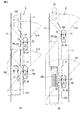
本発明に係る第1の実施形態の運転支援装置1について、当該装置を搭載した車両(自車100)を例に図1から図4を参照して説明する。本明細書では、自車100の進行方向を基準に運転者から見て「右」と「左」を定義する。また、車両通行帯Lが日本の道路交通法に基づく左側通行である場合を前提に説明する。このとき、図3に示すように車両通行帯Lは、少なくとも片側2車線である場合を想定する。自車100が走行する車線を第1の車線L1とし、この第1の車線L1に平行して設けられて自車100と同方向に他車200が走行する車線を第2の車線L2とする。図3及び図4の(A)及び(B)に示すように自車100が左側の車線を走行している場合、左側の車線を第1の車線L1と呼び、右側の車線を第2の車線L2と呼ぶ。これに対して図5の(A),(B)に示すように自車100が右側の車線を走行している場合、左側の車線を第2の車線L2と呼び、右側の車線を第1の車線L1と呼ぶ。
A
運転支援装置1は、自車100の運転者にとって死角となる後側方の第2の車線L2を走行する他車200を検出し、運転者がその他車200に気付かずに車線変更を行なおうとした場合に、自車100が他車200と衝突することを防止するために運転者に接近警報を報知するなど、接近抑制手段を作動させる。そして、本実施形態では、自車100が他車200の前方へ車線変更しようとする場合に、後方の他車200を検出するために自車100の後側方に設定される検出範囲14R,14Lを、他車200の大きさに応じて検出範囲14R,14Lの検出距離Dを後方へ大きくしている。これにより、大型の他車200の前方へ車線変更する際に自車100の後方に十分な車間距離を確保することができるので他車200による威圧感を覚えることなく、車線変更を行うタイミングを計ることができる。
The driving
第1の実施形態の運転支援装置1は、図1のブロック図に示すように、他車両検出部12と他車情報取得部13と接近検出部14と接近抑制部15と設定部16とを備える。この運転支援装置1は、従来の追越車接近警報(車線変更アシスト(Lane-change-Assist:LCA))又は後側方死角警報(Blind-Spot-Warning:BSW)を構成する部分から得られる情報を一部利用している。追越車線接近警報LCA又は後方死角警報BSWは、運転支援装置1の一部として自車100の電子制御ユニットECUに接続されて統合制御されている。
As shown in the block diagram of FIG. 1, the driving
図1に示すブロック図は、自車100に搭載されて第1の実施形態の運転支援装置1に連携する他の構成を運転支援装置1とともに示す。図1によれば、自車100には、第1のカメラ(前方カメラ)21と、第2のカメラ(右後側方カメラ及び左後側方カメラ)22,23と、レーダ(右後方ミリ波レーダ及び左後方ミリ波レーダ)24,25と接近信号を基に点灯される表示灯であるLCAインジケータ31と、接近抑制手段として接近警報を視覚的に出力する警告灯41と、接近抑制手段として接近警報を聴覚的に警告音として出力するスピーカ(ブザー)42と、接近抑制手段として接近警報を触覚的に振動にして出力する振動発生機43と、自車100の速度を検出する速度センサ51と、方向指示器を作動させるための方向指示レバー52と、車外に対して自車100の移動方向を示す方向指示灯53と、ステアリングの回動角度を検知する舵角検知センサ54と、を少なくとも備えている。図3は、自車100が片側2車線の車両通行帯Lの左側車線を走行している状態を模式的に示す平面図であって、第1のカメラ21の撮影範囲21Aと、第2尾カメラ22,23の撮影範囲22A,23Aと、レーダ24,25の観測範囲24A,25Aと、接近検出部14によって設定される検出範囲14R,14Lと、設定部16によって設定され検出範囲14R,14Lの最後端である検出距離Dとを模式的に示す。
The block diagram shown in FIG. 1 shows the other structure which is mounted in the
他車両検出部12は、第1の車線L1に隣接する第2の車線L2を走行する他車200を検出する。本実施形態では、図1及び図3に示すように、自車100の前方を走行する他車200を検出する手段として第1のカメラ(前方カメラ)21を、自車100の側方よりも後方(後側方)の他車200を検出する手段として第2のカメラ(右後側方カメラ及び左後側方カメラ)22,23を、それぞれ自車100が備えている。
The other
第1のカメラ21は、自車100の前方に向けて車体に設置されており、少なくとも第2の車線L2を画角に含む撮影範囲21Aが設定されている。図3では、自車100の前方に扇形に撮影範囲21Aを示しているが、実際の撮影範囲21Aは、第1のカメラ21で撮影できる範囲に及ぶ。本実施形態において第1のカメラ21は、バックミラーとフロントガラスとの間に設置されており、自車100が右側の車線及び左側の車線のどちらを走行していてもよいように左右均等に撮影する。
The
また、第2のカメラ22,23は、自車100の後方に向けて車体に設置されており、本実施形態では、図3に示すように右側及び左側のドアミラー101,102にそれぞれ内蔵されている。第2のカメラ22,23の撮影範囲22A,23Aは、図3に示されるように、右後方の死角及び左後方の死角となる範囲からそれぞれ第2の車線L2が画角に入るように設定されている。
The
撮影条件の良い場合には、第1のカメラ21及び第2のカメラ22,23はいずれも数百メートル先までの範囲を撮影できる。他車両検出部12は、第1のカメラ21及び第2のカメラ22,23で取得された映像の中から画像解析によって、第2の車線L2を走行する他車200を検出する。
When the photographing conditions are good, both the
さらに、本実施形態では、図1及び図3に示すように、他車200を検出する手段としてレーダ24,25を自車100が備えている。本実施形態ではレーダ24,25としてミリ波レーダを採用しており、車体のリアバンパ103の右端部に右後方ミリ波レーダ(24)、左端部に左後方ミリ波レーダ(25)をそれぞれ内蔵している。これらのレーダ24,25は、自車100の側方よりも後方の第2の車線L2を観測範囲24A,25Aに設定されている。レーダ24,25を採用することで、自車100と他車200の相対速度及び車間距離、自車100に対して他車200が位置する範囲を正確に検出できる。ミリ波レーダの代わりに赤外線レーダや超音波レーダ、レーザーレーダでもよい。ミリ波レーダを採用することで、雨や霧などの気象条件や日照条件にあまり作用されることなく他車200を検出できる。
Furthermore, in this embodiment, as shown in FIGS. 1 and 3, the
他車情報取得部13は、他車両検出部12が他車200を検出するとその他車200の少なくとも大きさを含む情報を取得する。本実施形態の場合、自車100の大きさは、ECUに接続された記憶部などに予め登録されている情報から得られる。また、自車100の前方に位置する他車200は第1のカメラ(前方カメラ)21で取得された映像を画像解析することによって、自車100の後方に位置する他車200は第2のカメラ(右後側方カメラ又は左後側方カメラ)22,23で取得された映像を画像解析することによって、他車200の大きさが判別する、あるいは背景や周辺の他車200との比較から他車200の大きさ及び自車100との相対的な大きさの差を計算することができる。さらに、他車200の大きさを求めた映像から画像解析を行って他車200の占有容積を算出し、他車の重量を推測することも可能である。他車200の重量の情報は他車200の制動距離を推定するのに有効である。
The other vehicle
また、他車200の情報として大きさ以外に速度を含むことも可能である。自車100の速度は速度センサ51で取得し、他車200の速度は第1のカメラ21及び第2のカメラ22,23で取得される映像を基に算出できる。他車200の速度についていえば、本実施形態ではさらにレーダ(右後方ミリ波レーダ及び左後方ミリ波レーダ)24,25を備えているので、レーダ24,25の観測範囲24A,25Aに他車200が入れば、これらの計測データを基により正確な他車200の位置及び速度を取得できる。
Moreover, it is also possible to include speed in addition to the size as information of the
接近検出部14は、自車100から後方へ検出距離Dに設定される図3に示す検出範囲14R,14L内に他車200があることを検出している場合に接近信号を出力する。本実施形態の場合、接近検出部14は、接近信号を自車100の運転者に報知する表示器を含む。表示器は、右のサイドミラー101及び左のサイドミラー102のそれぞれに設けられるLCAインジケータ31である。右後側方カメラ(22)及び右後方ミリ波レーダ(24)で他車200を検出している場合、右のサイドミラー101に設けられたLCAインジケータ31を点灯させ、左後側方カメラ(23)及び左後方ミリ波レーダ(25)で他車200を検出している場合、左のサイドミラー102に設けられたLCAインジケータ31を点灯させる。
The
また、接近抑制部15は、接近検出部14から接近信号が出力されている間に他車200が検出された側と同じ側に自車100を移動させる向きに方向指示器が操作されて作動していることを検出して接近抑制手段を作動させる。本実施形態の場合、方向指示器は、方向指示レバー52及び方向指示灯53を含み、方向指示レバー52が操作されて方向指示灯53が点灯する場合、すなわち方向指示器が作動された場合に、作動信号を出力する。したがって、接近抑制部15は、接近検出部14から出力される接近信号と方向指示器から出力される作動信号とを検出すると接近抑制手段を作動させる。
Further, the
接近抑制部15は、接近抑制手段として、自車100の運転者に見える位置に点灯される警告灯41、自車100の車室内に設置されるスピーカ(ブザー)42、及びステアリングに伝達される振動を発生させる振動発生機43を含んでいる。接近抑制手段を作動させるとは、警告灯41を点灯させることによって、スピーカ(ブザー)42で警告音を発生させることによって、振動発生機43でステアリングに振動を加えることによって、それぞれ自車100が第1の車線L1から第2の車線L2へ車線変更しようとする際に検出範囲14R,14L内に他車200が居ることを自車100の運転者に報知することをいう。なお、スピーカ42は、警告音を発生させる代わりに、第2の車線L2の検出範囲14R,14Lに他車200が居ることや、そのまま車線変更をすると危険であることを報知する等、運転者に対してアナウンスする音声であってもよい。
The
設定部16は、第1のカメラ21や第2のカメラ22,23によって撮影された映像から他車200の大きさを判別し、普通自動車の大きさよりも大きい場合に、または自車100よりも大きい場合に、あるいは予め設定された大きさの車両よりも大きい場合に、自車100の後方の第2の車線L2に設定される検出範囲14R,14Lの検出距離を大きくする、すなわち自車100の後方へ検出範囲14R,14Lを拡張(延長)する。このとき設定部16は、自車100の大きさと他車200の大きさの差が大きいほど検出範囲14R,14Lの検出距離Dを大きくする。自車100の後方の第2の車線L2を走行する他車200が大型トラックやトレーラ等、サイズの大きい車両である場合に検出距離Dを大きくすることで、他車200を早めに検出し、運転者に報知する時間を十分に確保する。また、運転者は検出距離D内に車体の大きな他車200が入っていないことをLCAインジケータ31で確認することで、他車200との間に十分な車間距離が確保されていることを知ることができ、安心して車線変更を行なえる。
The setting
また、本実施形態において、図1に示すように、自車100がステアリングの舵角を変更するアシスト装置18を備える場合、接近抑制手段には、アシスト装置18で発生させる操舵反力を含む。操舵反力は、第2の車線L2へ接近することを抑制する方向へ作用する。アシスト装置18でステアリングを回動させるべき回転角度は、舵角検知センサ54でフィードバック制御される。
In the present embodiment, as shown in FIG. 1, when the
以上のように構成された運転支援装置1は、図2に示すフローチャートにしたがって制御処理される。以下に、自車100及び他車200が片側2車線の車両通行帯Lを走行している場合の運転支援装置1の動作について、後方から接近する他車200の前方へ自車100が車線変更する場合(図2及び図4)、及び追い越した他車200の前方へ自車100が車線変更する場合の2つの状況について、それぞれ説明する。また、いずれも他車200の前方へ自車100が車線変更を行う場合であるが、図4は自車100の速度の方が他車200の速度よりも遅い場合、図5は自車の速度の方が他車200の速度よりも速い場合を示している。
The driving
(後方から接近する他車の前方へ車線変更する場合)
まず、自車100の前方を走行する車両(他車201)を追い越すために自車100が第2の車線L2へ車線変更を行なう場合に後方から他車200が接近してくる状況について説明する。図4において、自車100が走行している左側の車線が第1の車線L1であり、その右側を同方向に他車200が走行する車線が第2の車線L2となる。さらに図4では、自車100が走行する第1の車線L1の前方に自車100よりも速度の遅い他車201が走行しており、この他車201を自車100が追い越そうとしている状態である。
(When changing lanes ahead of other vehicles approaching from behind)
First, a description will be given of a situation in which the
図4の(A)は自車100の車体の大きさに対して他車200の車体の大きさがほぼ同じである場合、図4の(B)は自車100の車体の大きさに対して他車200の車体の大きさの方が大きい場合を示しており、検出範囲14R,14Lの検出距離Dは、(A)の場合よりも(B)の場合の方が後方へ大きく設定されている。図4の(A)及び(B)中において、下側に図示された他車200は、自車100の検出範囲14Rの検出距離Dから外れており、自車100は、第2の車線L2に破線で図示された位置に車線変更を行なえる状態である。
4A shows a case where the size of the vehicle body of the
後方から接近してくる他車200の前方へ車線変更する場合の運転支援装置1の制御フローは図2によって説明される。自車100の運転支援装置1において、自車100の速度が所定の速度以上で安定走行していることをECUが速度センサ51で検出すると、図2のフローチャートのように、ECUによってLCA(BSW)が作動(S1)され、自車100の運転支援装置1が機能し始める。運転支援装置1が起動すると、図2に示すように検出範囲14R,14Lの検出距離Dを初期化(S2)する。次に、第1のカメラ21及び第2のカメラ22,23で取得された映像を基に他車両検出部12で自車100の前後の他車200を検出(S3)する。他車が検出された場合、さらに、他車情報取得部13で他車200の大きさを少なくとも含む情報を取得(S4)する。本実施形態では、大きさとともに速度も含む情報を取得する。
The control flow of the driving
設定部16は、予め設定されている自車100(または普通車)の大きさと他車200の大きさを比較(S5)し、他車200の方が大きい場合すなわち図4(B)の場合は、検出範囲14R,14Lの検出距離Dを後方へ大きく設定(S6)する。他車200と自車100の大きさがほぼ変わらない場合すなわち図4(A)の場合は、そのままS6を飛ばして次の工程に進む。次に、設定部16は、他車情報取得部13が取得した他車200の速度と速度センサ51で得られた自車100の速度とを比較(S7)し、他車200の速度の方が速い場合はさらに検出距離Dを後方へ大きくする(S8)。自車200の速度の方が速い場合は検出距離Dを小さくする(S9)。
The setting
ここで図4では、自車100の前方の他車201を追い越すために第2の車線L2へ車線変更するので、方向指示器が作動しているか確認(S10)する。方向指示器が作動している場合、上述のごとく設定された検出範囲14R,14Lに他車200が入っているか接近検出部14で確認(S11)する。方向指示器が作動していない場合は、運転者がこの段階で検出されている他車200の前方へ車線変更を行わないことを意味するので、S2の前へ戻る。
Here, in FIG. 4, since the lane is changed to the second lane L2 in order to pass the other vehicle 201 in front of the
S11において検出範囲14R,14Lに他車200を検出した場合、他車200を検出した側の表示器であるLCAインジケータ31を点灯(S12)させる。図4では、自車100が左側の車線を走行しているので、右側の車線の他車200を検出することで右側のLCAインジケータ31が点灯される。LCAインジケータ31が点灯している状態は、他車200が検出範囲14Rに居ることを意味するので、舵角検知センサ54の検出信号を基に自車100が右側の第2の車線L2へ接近していないか確認(S13)する。接近していない場合は、運転者がLCAインジケータ31に気付いており第2の車線L2の他車200の様子をうかがっている状態であるから、S10の前に戻って方向指示器が引き続き作動しているか確認(S10)する。方向指示器を作動させたまま、後方から接近してきた他車200が自車100の横を通り過ぎるのを待っている間は、S10からS13の制御フローを繰り返すこととなる。運転者が車線変更をあきらめて方向指示器を停止させると制御フローはS10からS2へ戻る。
When the
S13において運転者がLCAインジケータ31に気付かずに第2の車線L2に接近した場合、舵角検知センサ54から検出信号が出力されるので、これを基に接近抑制部14は、接近抑制手段を作動(S14)させる。運転支援装置1は、接近抑制手段として警告灯41を点灯させるとともに、接近抑制手段としてスピーカ(ブザー)42で警告音を出力する。また、接近抑制手段として振動発生機43でステアリングに振動を発生させてもよい。本実施形態の場合、さらにアシスト装置18を自車が装備しているので、接近抑制手段としてアシスト装置18で第2の車線L2から離れる方向(第1の車線L1の中央に向かう方向)へ自車100を誘導するように操舵反力を発生させてもよい。接近抑制手段が作動することで自車100が第1の車線L1に維持されるので、第2の車線L2を後方から接近してくる他車200との衝突は免れる。
When the driver approaches the second lane L2 without noticing the
接近抑制手段が作動(S14)した後は、制御フローはS10の前に戻る。自車100の運転者が方向指示器を作動させたまま他車200が通り過ぎるのを待つ場合は、S10からS13の制御フローを繰り返す。なお、S10からS13の制御フローを繰り返す間に、S10で方向指示器が停止されたことが確認されるか、S13において第2の車線L2へ接近しなくなったことが舵角検知センサ54で確認されると、接近抑制手段は解除される。
After the approach suppression means is activated (S14), the control flow returns to before S10. When the driver of the
S10で方向指示器が作動されていることが確認され、S11で検出範囲14Rに他車200が検出されなかった場合、すなわち、図4(A),(B)に示すように他車200が検出範囲14Rから外れていることを意味する。検出範囲14Rに他車200が居ないので、表示器であるLCAインジケータ31は消灯(S15)され、接近抑制手段が作動していた場合もここで停止(S16)され、車線変更が可能(S17)な状態となる。これにより自車100が第2の車線L2へ車線変更すると制御フローはS2に戻り、検出距離Dが初期化される。
In S10, it is confirmed that the direction indicator is operated, and in S11, when the
以上のように、後方から接近してくる他車200の前方へ車線変更する場合、運転支援装置1によって、接近してくる他車200の大きさを基に接近検出部14の検出範囲14R,14Lの検出距離Dが設定される、すなわち他車200が自車100よりも大きい場合には検出距離Dが大きく設定されるので、運転者は、方向指示器を作動させた時にLCAインジケータ31が点灯されるか否かを確認することで、後方から接近してくる他車200の前方へ安全に車線変更できるか容易に判断できる。
As described above, when the lane is changed to the front of the
(追い越した他車の前方へ車線変更する場合)
次に、自車100の前方を走行していた他車200を追い越すために右側の車線に既に車線変更を行っており、他車200を追い越した後で、他車200の前方へ再び車線変更を行おうとする状況について説明する。つまり、図4において左側の車線から右側の車線へ車線変更した後、再び左側の車線へ戻る場合である。図5では、自車100が走行している右側の車線が第1の車線L1であり、その左側を同方向に他車200が走行する車線が第2の車線L2となる。
(When changing lanes ahead of other overtaking vehicles)
Next, in order to overtake the
図5の(A)は自車100の車体の大きさに対して他車200の車体の大きさがほぼ同じである場合を示している。図5の(B)は自車100の車体の大きさに対して他車200の車体の大きさの方が大きい場合を示している。検出範囲14R,14Lの検出距離Dは、(A)の場合よりも(B)の方が後方へ大きく設定されている。また、図4の場合に比べて図5の場合の方が、自車100の速度が他車200の速度よりも速いので、検出範囲14R,14Lの検出距離Dは、図5の方が図4よりも少し小さく設定されている。
FIG. 5A shows a case where the size of the vehicle body of the
図5の(A)及び(B)中において、下側に図示された自車100は他車200を追い越すために並走している状態であり検出範囲14Lに他車200が入る直前、上側に図示された自車100は他車を追い越して検出範囲14Lから他車200が外れ、第2の車線L2の上部に破線で図示された位置に車線変更ができるようになった状態を示す。
5 (A) and 5 (B), the
追い越した他車200の前方へ車線変更をする場合も図2のフローチャートに示した制御フローによって説明される。追い越す対象となる他車200は、第1のカメラ21によって取得された映像を基に、S3において既に検出されており、他車200の大きさや速度を含む情報も他車情報取得部13によって取得(S4)されている。そして、自車100の大きさと他車200の大きさを比較(S5)し、他車200が大きい場合すなわち図5(B)の場合には検出範囲14Lの検出距離Dを後方へ大きく設定(S6)する。他車200の大きさが自車100とほぼ変わらない場合すなわち図5(A)の場合にはS6の工程を飛ばし次に進む。
The case of changing lanes ahead of the overtaken
次に、他車200の速度と自車100の速度を比較(S7)する。図5では追い越した他車200の前方へ車線変更をする、すなわち自車100の方が他車200よりも速度が速いので、設定された検出距離Dを小さくしてもよい(S9)。ただし、他車200の大きさが自車100よりも大きい場合に検出範囲を大きく設定したことはそのまま維持されることが好ましい。したがって、他車200と自車100の大きさを比較したS5において他車200が大きかった場合、検出距離Dを大きく設定(S6)したあと、S10に進んでもよい。つまり、自車100と他車200の大きさがほぼ同じである場合に限り、自車100と他車200の速度を比較(S7)し、他車200が速い場合には検出距離Dを大きくし(S8)、他車200が遅い場合には検出距離Dを小さくする(S9)。
Next, the speed of the
検出された他車200の情報に基づいて検出範囲14Lの検出距離Dが設定されると方向指示器が作動されているかすなわち車線変更する意思があるか確認(S10)され、方向指示器が作動している場合は、検出範囲14Lに他車200が検出されるか確認(S11)される。検出範囲14Lに他車200が居る場合は、LCAインジケータ31を点灯させて、他車200との十分な車間距離が確保できていないことを運転者に報知する。第2の車線L2となる左側の車線に接近していないか確認(S12)され、舵角検知センサ54で第2の車線L2へ接近していることが検出されると接近抑制手段が作動(S14)される。接近抑制手段については、接近してくる他車200の前方へ車線変更することについて説明した上述のとおりである。また、方向指示器を作動させたまま、他車200との車間距離が確保されるまで待つ場合についても同様で、S10からS13の制御フローを繰り返す。
When the detection distance D of the
追い越した他車200に対して十分な車間距離が確保されるとS11で検出範囲14Lに他車200が検出されなくなるので、LCAインジケータ31が消灯(S15)されるとともに、接近抑制手段が作動していた場合には接近抑制手段が停止され(S16)、車線変更が可能(S17)となる。つまり、図5(A)及び(B)に破線で示された自車100の位置へ車線変更することができる。
If a sufficient inter-vehicle distance is secured for the overtaking
運転支援装置1は、図5(A)及び(B)からわかるように、他車200が自車100よりも大きい場合に検出距離Dを後方へ大きくして検出範囲14L(14R)を後方へ拡張(延長)する。したがって、自車100よりも大きい他車200(例えばトラックやバスなどの大型車)の前方へ車線変更する際に、運転者が威圧感を覚えることなく、また、大きい他車200の制動距離を配慮した充分な車間距離が確保される。
As can be seen from FIGS. 5A and 5B, the driving
本発明に係る第2の実施形態の運転支援装置1について、図6及び図7を参照して説明する。第2の実施形態の運転支援装置1において、第1の実施形態の運転支援装置1と同じ機能を有する構成には同じ符号を付し、その詳細な説明は、第1の実施形態の記載を参酌することとする。また、第2の実施形態では、自車100が有している機能を他車200も有していることを前提とする。
A driving
第2の実施形態では図6に示すように、全地球測位システム(GPS)の衛星Sから送信される電波情報を受信するアンテナ61と、GPSから得た電波情報から自車100の走行位置を算出する測位装置62と、車外から提供される運転情報を取得する通信機63とを自車100が備えている。アンテナ61は、測位装置62に接続されており、測位装置62は、他車両検出部12、他車情報取得部13に対して自車100の走行位置に関する情報を提供する。通信機63は、少なくとも他車両検出部12及び他車情報取得部13に対して接続されている。通信機63が取得する運転情報には、自車100の位置情報に基づく現在走行中の車両通行帯Lの地図情報、自車100の前方及び後方を走行する他車200の位置情報、その他車200から提供される少なくとも大きさに関する情報が少なくとも含まれる。他車200に関する情報として大きさの情報に加えて第1の実施形態のように速度の情報を含んでもよい。
In the second embodiment, as shown in FIG. 6, an
また、他車両検出部12は、測位装置62から得られた自車100の走行位置に基づいて、車両通行帯Lの前後の他車200を、通信機63を介して検出する。他車情報取得部13は、他車200の走行位置とともに少なくとも大きさを含む情報を、通信機63を介して取得する。大きさの情報に加えて重量の情報があればそれも取得することが好ましい。このとき通信機63は、自車100が走行している車両通行帯Lを通信範囲に含む基地局Kと通信して他車200の情報を取得してもよいし、自車100と同じ機能を有する他車200の通信機63と直接的に車車間通信を行って他車200の情報を取得してもよい。
Further, the other
第2の実施形態の運転支援装置1では、第1のカメラ21及び第2のカメラ22,23の代わりにGPSを利用するのであって、その他の構成及びその機能は第1の実施形態の運転支援装置1と同じである。なお、第1のカメラ21及び第2のカメラ22,23をGPSと併用してもよい。したがって、他車200を検出したり、他車200の情報に基づいて接近検出部14の検出範囲14R,14Lの検出距離Dを変更したりするための制御処理は、第1の実施形態の図2に示すフローチャートによって制御処理される場合と同じである。
In the driving
以上のように第2の実施形態の運転支援装置1は、GPS及び通信機63を利用することで、自車100の位置と他車200の位置を正確に把握し、自車100と他車200の大きさや重量などの情報を得ることで、自車100の後方の他車200との間に安全な車間距離を確保することができる。また、本実施形態の運転支援装置1は、GPSを利用するので、カーブや坂道の始終端、夜間、霧や雪のような悪天候など、視界の悪い状況であっても他車200を検出することに対して影響が少ない。さらに、前方及び後方の他車200が複数台ある場合、自車100に最も近い他車200に隠れているような他車200も検出できるので、これらの他車200に対しても安全距離を確保できる。
As described above, the driving
また、第2の実施形態の運転支援装置1は、GPSを利用するので、他車200が自車100と同方向に走行する場合に限らず、他車200が対向車である場合にも適用することができる。他車200が対向車である場合、他車両検出部12が前方から接近する他車200の情報を通信機63で取得すると、これに基づいて接近検出部14は自車100の前方に検出範囲14R,14Lを設定する。そして、第1の実施形態の図5に示したように自車100の前方を走行する他車201を追い越すような場合、あるいは、第1の車線L1上にある障害物を避ける場合など、対向車線である第2の車線L2へ車線変更する際に前方から接近する他車200に対して安全な距離を確保することができる。
In addition, since the driving
以上、本発明に係る運転支援装置1について第1及び第2の実施形態を用いて説明した。これらの実施形態は、本発明を実施するにあたって理解しやすくするための一例に過ぎず、これらの実施形態のみに限定されることを意図していない。したがって、本発明を実施するにあたってその趣旨を逸脱しない範囲で、各構成を同等の機能を有するものに置き換えて実施することも可能であり、それらもまた本発明に含まれる。また、各実施形態で説明した構成のいくつかを互いに組み合わせて、あるいは置き換えて実施されることも本発明に含まれる。
Heretofore, the driving
例えば、第1の実施形態と第2の実施形態を組み合わせ、他車両検出部12と他車情報取得部13と接近検出部14が、第1のカメラ21及び第2のカメラ22,23、レーダ24,25、GPSによる位置情報のそれぞれを適宜に利用して他車200の位置や大きさなどの情報を取得するとよい。
For example, the first embodiment and the second embodiment are combined, and the other
また、上述の第1の実施形態及び第2の実施形態のいずれの運転支援装置1において、自車100が走行している周辺の視界が悪い場合や路面状況が悪い場合などすなわち制動距離が延びるような場合、言い換えると、自車100のヘッドランプが点灯されている場合、自車100のワイパーが作動されている場合、自車100の外気温度が所定の温度以下である場合の少なくとも1つの場合に、設定部16は、他車200の大きさに応じてそれぞれの場合に対して設定された長さずつ、検出距離Dを後方へ延長することも好ましい。つまり、視界が悪い場合や路面状況が悪い場合の個々の条件によって検出距離Dを延長するべきそれぞれの値を足し合わせた長さをさらに検出距離Dとして加算する。自車100が追越運転において車線変更を行っている間に、自車100が減速しなければならない状況が生じても、他車200の制動距離を十分に確保することができる。
In any of the above-described
第1の実施形態において車両通行帯Lは、自車100が走行する第1の車線L1と他車200が走行する第2の車線L2との片側2車線である場合を例に説明したが、片側3車線以上の場合にもこの運転支援装置1を採用することができる。3車線のうちの中央の車線を自車100が走行する場合は、中央の車線が第1の車線L1となりその左右両側の車線が第2の車線L2となる。
In the first embodiment, the vehicle lane L has been described as an example in which the vehicle lane L is a two-lane lane on one side of the first lane L1 on which the
また、第1及び第2の実施形態のいずれの場合でも、自車100が走行する車両通行帯Lの三次元情報を取得する地形情報取得部をさらに備え、この地形情報取得部によって取得された車両通行帯Lの三次元情報と他車情報取得部13によって取得された他車200の情報とを基に、設定部16が接近検出部14の検出範囲14R,14Lの検出距離Dを設定してもよい。第1の実施形態において地形情報取得部は、第1のカメラ21や第2のカメラ22,23によって得られる映像情報から車両通行帯Lの地形(例えば勾配やカーブの半径)を算出することで車両通行帯Lの三次元情報を取得してもよい。また、第1の実施形態の場合、自車100がGPSの電波情報を受信するアンテナ61、測位装置62、及び通信機63を装備しているので、地形情報取得部はGPSから得られる自車100の位置情報を基に通信機63で地図情報を取得することによって車両通行帯Lの三次元情報を取得してもよい。
Further, in both cases of the first and second embodiments, the vehicle is further provided with a terrain information acquisition unit that acquires three-dimensional information of the vehicle traffic zone L in which the
地形情報取得部によって取得された三次元情報を基に、例えば、車両通行帯Lが直線状である場合に比べてカーブの半径が小さければ小さいほど、設定部16は、検出範囲14R,14Lの検出距離Dを大きく設定する。また、地形情報取得部によって取得された三次元情報のうち、車両通行帯Lの勾配に応じて接近検出部14の検出範囲14R,14Lの検出距離Dを設定することも好ましい。他車情報取得部13によって取得される他車200の情報と地形情報取得部によって取得される車両通行帯Lの三次元情報の両方を用いることで、自車100と他車200との車間距離を安全に確保することができる。
Based on the three-dimensional information acquired by the terrain information acquisition unit, for example, the smaller the radius of the curve as compared to the case where the vehicle lane L is linear, the setting
上述の各実施形態では、日本の道路交通法に基づくいわゆる左側通行であることを前提に説明したが、他国の道路交通法がいわゆる右側通行である場合には、適宜に左右を入れ替えて参酌されることとする。 In each of the above-described embodiments, description has been made on the assumption that the road traffic law is so-called left-hand traffic based on the Japanese road traffic law. However, when the road traffic law of other countries is so-called right-hand traffic, the right and left are interchanged appropriately. I will do it.
1…運転支援装置、12…他車両検出部、13…他車情報取得部、14…接近検出部、14R,14L…検出範囲、15…接近抑制部、16…設定部、18…アシスト装置(接近抑制手段)、21…第1のカメラ(前方カメラ)、21A…撮影範囲、22…第2のカメラ(右後側方カメラ)、22A…撮影範囲(画角)、23…第2のカメラ(左後側方カメラ)、23A…撮影範囲(画角)、24…レーダ(右後方ミリ波レーダ)、24A…観測範囲、25…レーダ(左後方ミリ波レーダ)、25A…観測範囲、31…LCAインジケータ(表示器)、41…警告灯(接近抑制手段)、42…スピーカ(ブザー)(接近抑制手段)、43…振動発生機(接近抑制手段)、52…方向指示レバー(方向指示器)、61…アンテナ、62…測位装置、63…通信機、100…自車、200…他車、L1…第1の車線、L2…第2の車線、D検出距離。
DESCRIPTION OF
Claims (7)
前記他車両検出部によって検出された前記他車の大きさを少なくとも含む情報を取得する他車情報取得部と、
前記自車から所定の検出距離の前記第2の車線に設定された検出範囲に前記他車が在ることを検出している場合に接近信号を出力する接近検出部と、
前記接近信号が出力されている間に前記他車が検出された側と同じ側に前記自車を移動させる向きに方向指示器が作動していることを検出して接近抑制手段を作動させる接近抑制部と、
前記他車の大きさと前記他車の大きさとを比較して、前記他車の大きさが前記自車の大きさよりも大きいほど前記検出距離を大きくする設定部と、を備える
ことを特徴とする運転支援装置。 An other vehicle detection unit for detecting another vehicle traveling in the second lane adjacent to the first lane in which the host vehicle is traveling;
Another vehicle information acquisition unit for acquiring information including at least the size of the other vehicle detected by the other vehicle detection unit;
An approach detection unit that outputs an approach signal when it is detected that the other vehicle is in a detection range set in the second lane of a predetermined detection distance from the own vehicle;
While the approach signal is being output, the approach that activates the approach suppression means by detecting that the direction indicator is operating in the direction to move the host vehicle to the same side as the side where the other vehicle is detected. A suppression unit;
A setting unit that compares the size of the other vehicle with the size of the other vehicle and increases the detection distance as the size of the other vehicle is larger than the size of the host vehicle. Driving assistance device.
ことを特徴とする請求項1に記載された運転支援装置。 The approach suppression means includes a warning light that is lit at a position that is visible to the driver of the host vehicle, a warning sound that is output inside the host vehicle, and a vibration that is output to the steering of the host vehicle. The driving support apparatus according to claim 1, comprising at least one.
前記接近抑制手段は、前記第2の車線へ接近することを抑制する方向へ前記アシスト装置で発生させる操舵反力を含む
ことを特徴とする請求項1又は請求項2に記載された運転支援装置。 When the host vehicle includes an assist device that changes the steering angle of the steering wheel,
The driving assistance device according to claim 1, wherein the approach suppression unit includes a steering reaction force generated by the assist device in a direction to suppress the approach to the second lane. .
ことを特徴とする請求項1から請求項3のいずれか1項に記載された運転支援装置。 The setting unit includes at least one of a case where a headlamp of the own vehicle is turned on, a wiper of the own vehicle is operated, and an outside temperature of the own vehicle is equal to or lower than a predetermined temperature. The driving according to any one of claims 1 to 3, wherein the detection distance is extended backward by a length set in each case according to the size of the other vehicle. Support device.
前記設定部は、前記自車の速度と前記他車の速度とを比較し、前記自車が前記他車よりも速い場合は前記検出距離を小さくし、前記自車が前記他車よりも遅い場合は前記検出距離を大きくする
ことを特徴とする請求項1から請求項4のいずれか1項に記載された運転支援装置。 The information of the other vehicle includes a speed of the other vehicle,
The setting unit compares the speed of the host vehicle with the speed of the other vehicle. If the host vehicle is faster than the other vehicle, the setting unit decreases the detection distance, and the host vehicle is slower than the other vehicle. 5. The driving support apparatus according to claim 1, wherein the detection distance is increased in some cases.
前記自車の後側方の前記第2の車線を画角に含む第2のカメラと、を前記自車が備える場合、
前記他車両検出部は、前記第1のカメラ及び前記第2のカメラの少なくとも一方によって取得された映像を基に前記他車を検出し、
前記他車情報取得部は、前記第1のカメラ及び前記第2のカメラの少なくとも一方によって取得された映像を基に前記他車の少なくとも大きさの情報を取得する
ことを特徴とする請求項1から請求項5のいずれか1項に記載された運転支援装置。 A first camera including, in an angle of view, the second lane ahead of the host vehicle;
When the host vehicle includes the second camera including the second lane on the rear side of the host vehicle in an angle of view,
The other vehicle detection unit detects the other vehicle based on an image acquired by at least one of the first camera and the second camera,
The said other vehicle information acquisition part acquires the information of the at least magnitude | size of the said other vehicle based on the image | video acquired by at least one of the said 1st camera and the said 2nd camera. The driving support device according to claim 5.
前記アンテナで受信した電波から前記自車の三次元位置を算出する測位装置と、
前記三次元位置を基に前記自車の近くの情報を取得する通信機と、を前記自車が備える場合、
前記他車両検出部は、前記三次元位置を基に前記通信機を介して前記他車を検出し、
前記他車情報取得部は、前記三次元位置を基に前記通信機を介して前記他車の少なくとも大きさを含む情報を取得する
ことを特徴とする請求項1から請求項5のいずれか1項に記載された運転支援装置。 An antenna for receiving radio waves output from satellites of the global positioning system;
A positioning device that calculates a three-dimensional position of the host vehicle from radio waves received by the antenna;
When the vehicle includes a communication device that acquires information near the vehicle based on the three-dimensional position,
The other vehicle detection unit detects the other vehicle via the communication device based on the three-dimensional position,
The said other vehicle information acquisition part acquires the information containing the at least magnitude | size of the said other vehicle via the said communication apparatus based on the said three-dimensional position, The any one of Claims 1-5 characterized by the above-mentioned. The driving assistance apparatus described in the item.
Priority Applications (4)
| Application Number | Priority Date | Filing Date | Title |
|---|---|---|---|
| JP2015248542A JP2017114155A (en) | 2015-12-21 | 2015-12-21 | Drive support device |
| CN201611177162.8A CN106898158B (en) | 2015-12-21 | 2016-12-19 | Drive supporting device |
| US15/385,303 US10486741B2 (en) | 2015-12-21 | 2016-12-20 | Driving support apparatus |
| EP16205731.9A EP3184394B1 (en) | 2015-12-21 | 2016-12-21 | Driving support apparatus |
Applications Claiming Priority (1)
| Application Number | Priority Date | Filing Date | Title |
|---|---|---|---|
| JP2015248542A JP2017114155A (en) | 2015-12-21 | 2015-12-21 | Drive support device |
Publications (1)
| Publication Number | Publication Date |
|---|---|
| JP2017114155A true JP2017114155A (en) | 2017-06-29 |
Family
ID=57680089
Family Applications (1)
| Application Number | Title | Priority Date | Filing Date |
|---|---|---|---|
| JP2015248542A Pending JP2017114155A (en) | 2015-12-21 | 2015-12-21 | Drive support device |
Country Status (4)
| Country | Link |
|---|---|
| US (1) | US10486741B2 (en) |
| EP (1) | EP3184394B1 (en) |
| JP (1) | JP2017114155A (en) |
| CN (1) | CN106898158B (en) |
Cited By (2)
| Publication number | Priority date | Publication date | Assignee | Title |
|---|---|---|---|---|
| US20220259824A1 (en) * | 2019-03-11 | 2022-08-18 | Caterpillar Inc. | Control Syste for a Work Machine |
| JP7414410B2 (en) | 2018-06-28 | 2024-01-16 | コンチネンタル オートモーティヴ ゲゼルシャフト ミット ベシュレンクテル ハフツング | Visibility distance determination based on vehicle dynamic field of view |
Families Citing this family (30)
| Publication number | Priority date | Publication date | Assignee | Title |
|---|---|---|---|---|
| CN107848465B (en) * | 2015-05-06 | 2021-06-01 | 麦格纳镜片美国有限公司 | Vehicle vision system with blind zone display and warning system |
| KR101946220B1 (en) * | 2015-07-28 | 2019-02-08 | 닛산 지도우샤 가부시키가이샤 | Driving control method and driving control device |
| JP2017114155A (en) * | 2015-12-21 | 2017-06-29 | 三菱自動車工業株式会社 | Drive support device |
| JP6602683B2 (en) * | 2016-02-05 | 2019-11-06 | 株式会社東芝 | Charging device and positional deviation detection method |
| DE102016202829A1 (en) * | 2016-02-24 | 2017-08-24 | Bayerische Motoren Werke Aktiengesellschaft | Device for transverse guidance support for a road-bound vehicle |
| KR101838968B1 (en) * | 2016-04-21 | 2018-04-26 | 엘지전자 주식회사 | Driving assistance Apparatus for Vehicle |
| US10453344B2 (en) * | 2017-02-16 | 2019-10-22 | Panasonic Intellectual Corporation Of America | Information processing apparatus and non-transitory recording medium |
| US10282998B2 (en) * | 2017-03-17 | 2019-05-07 | Denso International America, Inc. | Vehicle system and vehicle controller for controlling vehicle |
| US10902728B2 (en) * | 2017-04-26 | 2021-01-26 | Ford Global Technologies, Llc | Blind spot object detection |
| US10319228B2 (en) | 2017-06-27 | 2019-06-11 | Waymo Llc | Detecting and responding to sirens |
| JP6744269B2 (en) * | 2017-09-06 | 2020-08-19 | 本田技研工業株式会社 | Driving support device and driving support method |
| CN108010383A (en) * | 2017-09-29 | 2018-05-08 | 北京车和家信息技术有限公司 | Blind zone detection method, device, terminal and vehicle based on driving vehicle |
| DE102017223431B4 (en) * | 2017-12-20 | 2022-12-29 | Audi Ag | Method for assisting a driver of a motor vehicle when overtaking; motor vehicle; as well as system |
| JP6592074B2 (en) * | 2017-12-28 | 2019-10-16 | 本田技研工業株式会社 | Vehicle control device, vehicle control method, program, and information acquisition device |
| JP7043965B2 (en) * | 2018-05-09 | 2022-03-30 | スズキ株式会社 | Vehicle information display device |
| JP7001541B2 (en) * | 2018-06-04 | 2022-01-19 | 本田技研工業株式会社 | Vehicle control devices, vehicle control methods and programs |
| KR102106347B1 (en) * | 2018-07-25 | 2020-05-04 | 주식회사 만도 | Rear side alarm device and rear side alarm method thereof |
| RU2762150C1 (en) * | 2018-09-17 | 2021-12-16 | Ниссан Мотор Ко., Лтд. | Method for forecasting vehicle behavior and device for forecasting vehicle behavior |
| EP3865904A4 (en) * | 2018-10-12 | 2022-06-22 | Kyocera Corporation | Electronic device, electronic device control method, and electronic device control program |
| US20200132803A1 (en) * | 2018-10-26 | 2020-04-30 | Fleetmind Seon Solutions Inc. | Radar module for use with traffic monitoring and predictive analysis systems |
| CN109515448B (en) * | 2018-12-12 | 2021-06-01 | 安徽江淮汽车集团股份有限公司 | Automatic driving sensor arrangement method and structure |
| US11046321B2 (en) * | 2019-03-13 | 2021-06-29 | GM Global Technology Operations LLC | Adaptive control of automated lane change in vehicle |
| CN110077350A (en) * | 2019-03-22 | 2019-08-02 | 上海思致汽车工程技术有限公司 | His a kind of vehicle blind zone alert system |
| CN110239532B (en) * | 2019-05-20 | 2020-12-01 | 浙江吉利控股集团有限公司 | Vehicle lane change assisting method, device, terminal and storage medium |
| CN112083419B (en) * | 2019-05-27 | 2023-12-26 | 鼎天国际股份有限公司 | Radar system with vehicle assistance function having a field of view greater than 160 degrees |
| US11410545B2 (en) * | 2019-07-19 | 2022-08-09 | Ford Global Technologies, Llc | Dynamic vehicle perimeter definition and reporting |
| KR20210017315A (en) * | 2019-08-07 | 2021-02-17 | 엘지전자 주식회사 | Obstacle warning method of vehicle |
| KR20220029843A (en) * | 2020-08-31 | 2022-03-10 | 현대모비스 주식회사 | Rear side warning system and method for vehicle |
| CN112633258B (en) * | 2021-03-05 | 2021-05-25 | 天津所托瑞安汽车科技有限公司 | Target determination method and device, electronic equipment and computer readable storage medium |
| CN115547102A (en) * | 2022-08-15 | 2022-12-30 | 北京罗克维尔斯科技有限公司 | Vehicle avoiding method, device, equipment, medium and vehicle |
Citations (5)
| Publication number | Priority date | Publication date | Assignee | Title |
|---|---|---|---|---|
| JP2000207697A (en) * | 1999-01-19 | 2000-07-28 | Toyota Motor Corp | Device for monitoring periphery of vehicle |
| US20070078601A1 (en) * | 2005-10-05 | 2007-04-05 | Shinichi Nakano | Information provision apparatus and driving assistance system using the same |
| JP2014205457A (en) * | 2013-04-15 | 2014-10-30 | 株式会社デンソー | Vehicle contact prevention system |
| JP2015110403A (en) * | 2013-10-30 | 2015-06-18 | 株式会社デンソー | Travel control device, server, and on-vehicle device |
| JP2015189404A (en) * | 2014-03-28 | 2015-11-02 | マツダ株式会社 | Lane keeping controller |
Family Cites Families (44)
| Publication number | Priority date | Publication date | Assignee | Title |
|---|---|---|---|---|
| ES2391556T3 (en) | 2002-05-03 | 2012-11-27 | Donnelly Corporation | Object detection system for vehicles |
| DE102004019651A1 (en) * | 2004-04-22 | 2005-11-17 | Siemens Ag | Blind spot sensor system |
| US7720580B2 (en) * | 2004-12-23 | 2010-05-18 | Donnelly Corporation | Object detection system for vehicle |
| DE102005013669A1 (en) | 2005-03-14 | 2006-09-21 | Walter Ostertag | Method for operating motor vehicle involves transfer of information to driver of motor vehicle during forward drive is based on signal supplied by detection device |
| US20070018801A1 (en) * | 2005-07-25 | 2007-01-25 | Novotny Steven J | Digital voice/visual warning, alert, and status system for vehicles utilizing laser sensors |
| US7602276B2 (en) * | 2007-01-17 | 2009-10-13 | Visteon Global Technologies, Inc. | Variable blind spot warning system |
| US7612658B2 (en) * | 2007-04-11 | 2009-11-03 | Ford Global Technologies, Inc. | System and method of modifying programmable blind spot detection sensor ranges with vision sensor input |
| JP5061776B2 (en) * | 2007-08-03 | 2012-10-31 | 日産自動車株式会社 | Vehicle travel control device and vehicle travel control method |
| JP5347257B2 (en) * | 2007-09-26 | 2013-11-20 | 日産自動車株式会社 | Vehicle periphery monitoring device and video display method |
| US8310353B2 (en) * | 2008-03-31 | 2012-11-13 | Honda Motor Co., Ltd. | Vehicle blind spot detection and indicator system |
| JP2010073134A (en) * | 2008-09-22 | 2010-04-02 | Aisin Seiki Co Ltd | Vehicle surrounding recognition support system |
| JP4883248B2 (en) * | 2009-06-02 | 2012-02-22 | トヨタ自動車株式会社 | Vehicle periphery monitoring device |
| JP5375752B2 (en) | 2009-07-15 | 2013-12-25 | 日産自動車株式会社 | Vehicle driving support device |
| EP2473871B1 (en) * | 2009-09-01 | 2015-03-11 | Magna Mirrors Of America, Inc. | Imaging and display system for vehicle |
| US9292471B2 (en) * | 2011-02-18 | 2016-03-22 | Honda Motor Co., Ltd. | Coordinated vehicle response system and method for driver behavior |
| US8681016B2 (en) * | 2011-02-25 | 2014-03-25 | Volkswagen Ag | Driver assistance system |
| US8589014B2 (en) * | 2011-06-01 | 2013-11-19 | Google Inc. | Sensor field selection |
| JP5713106B2 (en) * | 2011-07-26 | 2015-05-07 | トヨタ自動車株式会社 | Vehicle identification system and vehicle identification device |
| US20130181860A1 (en) * | 2012-01-16 | 2013-07-18 | Ford Global Technologies, Llc | Radar based multifunctional safety system |
| CN104115186B (en) * | 2012-02-23 | 2018-08-28 | 日产自动车株式会社 | Stereoscopic article detection device |
| US9180882B1 (en) * | 2012-06-20 | 2015-11-10 | Google Inc. | Avoiding blind spots of other vehicles |
| KR101409747B1 (en) * | 2012-12-28 | 2014-07-02 | 현대모비스 주식회사 | Lateral control apparatus of vehicle and Control method of the same |
| US9523984B1 (en) * | 2013-07-12 | 2016-12-20 | Google Inc. | Methods and systems for determining instructions for pulling over an autonomous vehicle |
| US9323993B2 (en) * | 2013-09-05 | 2016-04-26 | Xerox Corporation | On-street parking management methods and systems for identifying a vehicle via a camera and mobile communications devices |
| CN103909926B (en) * | 2014-03-31 | 2016-08-10 | 长城汽车股份有限公司 | The lateral collision-proof method of vehicle, equipment and system |
| KR101596751B1 (en) * | 2014-09-26 | 2016-02-23 | 현대자동차주식회사 | Method and apparatus for displaying blind spot customized by driver |
| US9493117B2 (en) * | 2014-10-08 | 2016-11-15 | Ford Global Technologies, Llc | Vehicle blind spot system operation with trailer tow |
| US10032369B2 (en) * | 2015-01-15 | 2018-07-24 | Magna Electronics Inc. | Vehicle vision system with traffic monitoring and alert |
| US20160231746A1 (en) * | 2015-02-06 | 2016-08-11 | Delphi Technologies, Inc. | System And Method To Operate An Automated Vehicle |
| US10678261B2 (en) * | 2015-02-06 | 2020-06-09 | Aptiv Technologies Limited | Method and apparatus for controlling an autonomous vehicle |
| EP3257034B1 (en) * | 2015-02-10 | 2020-04-08 | Ridar Systems LLC | Proximity awareness system for motor vehicles |
| US20160252610A1 (en) * | 2015-02-26 | 2016-09-01 | Delphi Technologies, Inc. | Blind-spot radar system with improved semi-trailer tracking |
| US9725091B2 (en) * | 2015-07-02 | 2017-08-08 | Cummins, Inc. | Vehicle speed management integrated with vehicle monitoring system |
| KR101868318B1 (en) * | 2015-07-28 | 2018-06-15 | 닛산 지도우샤 가부시키가이샤 | Driving control method and driving control device of traveling device |
| EP3330942B1 (en) * | 2015-07-28 | 2019-12-11 | Nissan Motor Co., Ltd. | Method for controlling travel control device, and travel control device |
| JP6451855B2 (en) * | 2015-07-28 | 2019-01-23 | 日産自動車株式会社 | Travel control method and travel control apparatus |
| KR101946220B1 (en) * | 2015-07-28 | 2019-02-08 | 닛산 지도우샤 가부시키가이샤 | Driving control method and driving control device |
| JP6639194B2 (en) * | 2015-11-06 | 2020-02-05 | トヨタ自動車株式会社 | Information display device |
| DE102015223176A1 (en) * | 2015-11-24 | 2017-05-24 | Conti Temic Microelectronic Gmbh | Method and device for determining occlusion areas in the vehicle environment of a vehicle |
| JP2017114155A (en) * | 2015-12-21 | 2017-06-29 | 三菱自動車工業株式会社 | Drive support device |
| US9994151B2 (en) * | 2016-04-12 | 2018-06-12 | Denso International America, Inc. | Methods and systems for blind spot monitoring with adaptive alert zone |
| US10178531B2 (en) * | 2016-09-15 | 2019-01-08 | Qualcomm Incorporated | Methods and apparatus for efficient sensor data sharing in a vehicle-to-vehicle (V2V) network |
| US10262539B2 (en) * | 2016-12-15 | 2019-04-16 | Ford Global Technologies, Llc | Inter-vehicle warnings |
| KR102033883B1 (en) * | 2016-12-30 | 2019-11-08 | 현대자동차주식회사 | An apparatus and method for implementing LCDAS |
-
2015
- 2015-12-21 JP JP2015248542A patent/JP2017114155A/en active Pending
-
2016
- 2016-12-19 CN CN201611177162.8A patent/CN106898158B/en not_active Expired - Fee Related
- 2016-12-20 US US15/385,303 patent/US10486741B2/en not_active Expired - Fee Related
- 2016-12-21 EP EP16205731.9A patent/EP3184394B1/en not_active Not-in-force
Patent Citations (6)
| Publication number | Priority date | Publication date | Assignee | Title |
|---|---|---|---|---|
| JP2000207697A (en) * | 1999-01-19 | 2000-07-28 | Toyota Motor Corp | Device for monitoring periphery of vehicle |
| US20070078601A1 (en) * | 2005-10-05 | 2007-04-05 | Shinichi Nakano | Information provision apparatus and driving assistance system using the same |
| JP2007102577A (en) * | 2005-10-05 | 2007-04-19 | Kawasaki Heavy Ind Ltd | Information providing device and traveling support system using the same |
| JP2014205457A (en) * | 2013-04-15 | 2014-10-30 | 株式会社デンソー | Vehicle contact prevention system |
| JP2015110403A (en) * | 2013-10-30 | 2015-06-18 | 株式会社デンソー | Travel control device, server, and on-vehicle device |
| JP2015189404A (en) * | 2014-03-28 | 2015-11-02 | マツダ株式会社 | Lane keeping controller |
Cited By (3)
| Publication number | Priority date | Publication date | Assignee | Title |
|---|---|---|---|---|
| JP7414410B2 (en) | 2018-06-28 | 2024-01-16 | コンチネンタル オートモーティヴ ゲゼルシャフト ミット ベシュレンクテル ハフツング | Visibility distance determination based on vehicle dynamic field of view |
| US20220259824A1 (en) * | 2019-03-11 | 2022-08-18 | Caterpillar Inc. | Control Syste for a Work Machine |
| US12098521B2 (en) * | 2019-03-11 | 2024-09-24 | Caterpillar Inc. | Control system for a work machine |
Also Published As
| Publication number | Publication date |
|---|---|
| CN106898158B (en) | 2019-08-16 |
| EP3184394B1 (en) | 2018-09-26 |
| US20170174262A1 (en) | 2017-06-22 |
| CN106898158A (en) | 2017-06-27 |
| US10486741B2 (en) | 2019-11-26 |
| EP3184394A1 (en) | 2017-06-28 |
Similar Documents
| Publication | Publication Date | Title |
|---|---|---|
| JP2017114155A (en) | Drive support device | |
| US10449971B2 (en) | Travel control device | |
| CN108528460B (en) | Vehicle and vehicle control method | |
| US20170349212A1 (en) | Driving assistance device | |
| JP4517393B2 (en) | Driving assistance device | |
| JP6639194B2 (en) | Information display device | |
| KR102663017B1 (en) | Vehicle and method for controlling thereof | |
| JP2017116992A (en) | Drive support device | |
| JP2009271766A (en) | Obstacle detection device for automobile | |
| US10421397B2 (en) | Forward maneuvering assistance using head-up display | |
| KR20200017971A (en) | Vehicle and method for controlling thereof | |
| JP6063319B2 (en) | Lane change support device | |
| JP5838547B2 (en) | Driving assistance device | |
| JP6426232B1 (en) | Automatic run control device | |
| US20180236939A1 (en) | Method, System, and Device for a Forward Vehicular Vision System | |
| JP2017111732A (en) | Vehicle control apparatus | |
| JP2017189989A (en) | Lane keep apparatus | |
| US11545035B2 (en) | Driver notification system | |
| JPWO2018047232A1 (en) | Vehicle control device | |
| WO2019138769A1 (en) | Driving assistance control device for vehicle, driving assistance system for vehicle, and driving assistance control method for vehicle | |
| JP2019048631A (en) | Automatic travel control device | |
| JP6331233B2 (en) | Vehicle control device | |
| JP2010018080A (en) | Vehicular driving support device | |
| JP5166975B2 (en) | Vehicle periphery monitoring device and vehicle periphery monitoring method | |
| JP2018165096A (en) | Approach avoidance support device |
Legal Events
| Date | Code | Title | Description |
|---|---|---|---|
| A621 | Written request for application examination |
Free format text: JAPANESE INTERMEDIATE CODE: A621 Effective date: 20181130 |
|
| A977 | Report on retrieval |
Free format text: JAPANESE INTERMEDIATE CODE: A971007 Effective date: 20190823 |
|
| A131 | Notification of reasons for refusal |
Free format text: JAPANESE INTERMEDIATE CODE: A131 Effective date: 20190903 |
|
| A02 | Decision of refusal |
Free format text: JAPANESE INTERMEDIATE CODE: A02 Effective date: 20200303 |