US8072619B2 - Printing apparatus and method for controlling the same - Google Patents
Printing apparatus and method for controlling the same Download PDFInfo
- Publication number
- US8072619B2 US8072619B2 US12/082,314 US8231408A US8072619B2 US 8072619 B2 US8072619 B2 US 8072619B2 US 8231408 A US8231408 A US 8231408A US 8072619 B2 US8072619 B2 US 8072619B2
- Authority
- US
- United States
- Prior art keywords
- recording paper
- printing
- size
- print job
- printing apparatus
- Prior art date
- Legal status (The legal status is an assumption and is not a legal conclusion. Google has not performed a legal analysis and makes no representation as to the accuracy of the status listed.)
- Expired - Fee Related, expires
Links
- 238000000034 method Methods 0.000 title claims abstract description 63
- 230000008569 process Effects 0.000 claims abstract description 51
- 238000001514 detection method Methods 0.000 claims abstract description 45
- 238000012545 processing Methods 0.000 claims description 53
- 230000004044 response Effects 0.000 claims description 8
- 230000001934 delay Effects 0.000 claims description 2
- 210000000078 claw Anatomy 0.000 description 41
- 238000012546 transfer Methods 0.000 description 19
- 238000004891 communication Methods 0.000 description 13
- 230000003111 delayed effect Effects 0.000 description 6
- 230000001105 regulatory effect Effects 0.000 description 6
- 230000001276 controlling effect Effects 0.000 description 5
- 238000011161 development Methods 0.000 description 5
- 230000003287 optical effect Effects 0.000 description 5
- 238000003384 imaging method Methods 0.000 description 4
- 238000004140 cleaning Methods 0.000 description 3
- 230000000994 depressogenic effect Effects 0.000 description 3
- 230000005684 electric field Effects 0.000 description 3
- 230000015572 biosynthetic process Effects 0.000 description 2
- 238000012937 correction Methods 0.000 description 2
- 238000013523 data management Methods 0.000 description 2
- 230000002950 deficient Effects 0.000 description 2
- 238000010586 diagram Methods 0.000 description 2
- 238000007599 discharging Methods 0.000 description 2
- 239000011521 glass Substances 0.000 description 2
- 230000010365 information processing Effects 0.000 description 2
- 239000004973 liquid crystal related substance Substances 0.000 description 2
- 238000007726 management method Methods 0.000 description 2
- 238000007796 conventional method Methods 0.000 description 1
- 230000000694 effects Effects 0.000 description 1
- 230000006870 function Effects 0.000 description 1
- 239000000463 material Substances 0.000 description 1
- 230000007246 mechanism Effects 0.000 description 1
- 238000012986 modification Methods 0.000 description 1
- 230000004048 modification Effects 0.000 description 1
- 230000002093 peripheral effect Effects 0.000 description 1
- 108091008695 photoreceptors Proteins 0.000 description 1
- 238000012805 post-processing Methods 0.000 description 1
- 238000004080 punching Methods 0.000 description 1
- 238000004904 shortening Methods 0.000 description 1
- 239000002344 surface layer Substances 0.000 description 1
- 230000007306 turnover Effects 0.000 description 1
Images


Classifications
-
- B—PERFORMING OPERATIONS; TRANSPORTING
- B41—PRINTING; LINING MACHINES; TYPEWRITERS; STAMPS
- B41J—TYPEWRITERS; SELECTIVE PRINTING MECHANISMS, i.e. MECHANISMS PRINTING OTHERWISE THAN FROM A FORME; CORRECTION OF TYPOGRAPHICAL ERRORS
- B41J11/00—Devices or arrangements of selective printing mechanisms, e.g. ink-jet printers or thermal printers, for supporting or handling copy material in sheet or web form
- B41J11/0025—Handling copy materials differing in width
- B41J11/003—Paper-size detection, i.e. automatic detection of the length and/or width of copy material
-
- B—PERFORMING OPERATIONS; TRANSPORTING
- B41—PRINTING; LINING MACHINES; TYPEWRITERS; STAMPS
- B41J—TYPEWRITERS; SELECTIVE PRINTING MECHANISMS, i.e. MECHANISMS PRINTING OTHERWISE THAN FROM A FORME; CORRECTION OF TYPOGRAPHICAL ERRORS
- B41J13/00—Devices or arrangements of selective printing mechanisms, e.g. ink-jet printers or thermal printers, specially adapted for supporting or handling copy material in short lengths, e.g. sheets
- B41J13/0009—Devices or arrangements of selective printing mechanisms, e.g. ink-jet printers or thermal printers, specially adapted for supporting or handling copy material in short lengths, e.g. sheets control of the transport of the copy material
- B41J13/0027—Devices or arrangements of selective printing mechanisms, e.g. ink-jet printers or thermal printers, specially adapted for supporting or handling copy material in short lengths, e.g. sheets control of the transport of the copy material in the printing section of automatic paper handling systems
-
- G—PHYSICS
- G03—PHOTOGRAPHY; CINEMATOGRAPHY; ANALOGOUS TECHNIQUES USING WAVES OTHER THAN OPTICAL WAVES; ELECTROGRAPHY; HOLOGRAPHY
- G03G—ELECTROGRAPHY; ELECTROPHOTOGRAPHY; MAGNETOGRAPHY
- G03G15/00—Apparatus for electrographic processes using a charge pattern
- G03G15/50—Machine control of apparatus for electrographic processes using a charge pattern, e.g. regulating differents parts of the machine, multimode copiers, microprocessor control
-
- G—PHYSICS
- G03—PHOTOGRAPHY; CINEMATOGRAPHY; ANALOGOUS TECHNIQUES USING WAVES OTHER THAN OPTICAL WAVES; ELECTROGRAPHY; HOLOGRAPHY
- G03G—ELECTROGRAPHY; ELECTROPHOTOGRAPHY; MAGNETOGRAPHY
- G03G15/00—Apparatus for electrographic processes using a charge pattern
- G03G15/65—Apparatus which relate to the handling of copy material
- G03G15/6588—Apparatus which relate to the handling of copy material characterised by the copy material, e.g. postcards, large copies, multi-layered materials, coloured sheet material
- G03G15/6594—Apparatus which relate to the handling of copy material characterised by the copy material, e.g. postcards, large copies, multi-layered materials, coloured sheet material characterised by the format or the thickness, e.g. endless forms
-
- B—PERFORMING OPERATIONS; TRANSPORTING
- B41—PRINTING; LINING MACHINES; TYPEWRITERS; STAMPS
- B41J—TYPEWRITERS; SELECTIVE PRINTING MECHANISMS, i.e. MECHANISMS PRINTING OTHERWISE THAN FROM A FORME; CORRECTION OF TYPOGRAPHICAL ERRORS
- B41J11/00—Devices or arrangements of selective printing mechanisms, e.g. ink-jet printers or thermal printers, for supporting or handling copy material in sheet or web form
- B41J11/006—Means for preventing paper jams or for facilitating their removal
-
- G—PHYSICS
- G03—PHOTOGRAPHY; CINEMATOGRAPHY; ANALOGOUS TECHNIQUES USING WAVES OTHER THAN OPTICAL WAVES; ELECTROGRAPHY; HOLOGRAPHY
- G03G—ELECTROGRAPHY; ELECTROPHOTOGRAPHY; MAGNETOGRAPHY
- G03G2215/00—Apparatus for electrophotographic processes
- G03G2215/00362—Apparatus for electrophotographic processes relating to the copy medium handling
- G03G2215/00443—Copy medium
- G03G2215/00451—Paper
- G03G2215/00464—Non-standard format
-
- G—PHYSICS
- G03—PHOTOGRAPHY; CINEMATOGRAPHY; ANALOGOUS TECHNIQUES USING WAVES OTHER THAN OPTICAL WAVES; ELECTROGRAPHY; HOLOGRAPHY
- G03G—ELECTROGRAPHY; ELECTROPHOTOGRAPHY; MAGNETOGRAPHY
- G03G2215/00—Apparatus for electrophotographic processes
- G03G2215/00362—Apparatus for electrophotographic processes relating to the copy medium handling
- G03G2215/00535—Stable handling of copy medium
- G03G2215/00603—Control of other part of the apparatus according to the state of copy medium feeding
-
- G—PHYSICS
- G03—PHOTOGRAPHY; CINEMATOGRAPHY; ANALOGOUS TECHNIQUES USING WAVES OTHER THAN OPTICAL WAVES; ELECTROGRAPHY; HOLOGRAPHY
- G03G—ELECTROGRAPHY; ELECTROPHOTOGRAPHY; MAGNETOGRAPHY
- G03G2215/00—Apparatus for electrophotographic processes
- G03G2215/00362—Apparatus for electrophotographic processes relating to the copy medium handling
- G03G2215/00535—Stable handling of copy medium
- G03G2215/00717—Detection of physical properties
- G03G2215/00734—Detection of physical properties of sheet size
Definitions
- the present invention relates to a printing apparatus that prints recording paper by an electrophotographic image forming method or the like, and a method for controlling the printing apparatus.
- Some of this type of printing apparatus have sped up the printing process, so a plurality of print jobs can be executed one after another.
- JP 2000-330741A increases the duration for which a printing operation can be carried out continuously by omitting the initialization operation of the apparatus that is performed after each job, and performing print data management on a per job basis with a configuration in which jobs and print data are managed separately by a job management unit and a print data management unit, respectively, and a printing operation is continued if both a job to be printed and the print data are present during the printing operation, and an instruction to stop the printing operation is outputted only if it is necessary to perform an initialization operation after a stop request is made or a printer parameter is changed.
- a printing apparatus usually has a plurality of paper feed cassettes, so recording papers of given sizes can be placed and loaded in the paper feed cassettes.
- recording paper is placed and loaded in a paper feed cassette, the size of the recording paper loaded in the paper feed cassette is inputted/instructed.
- the paper feed cassette that contains the recording paper of the size set by this print job is selected, and the recording paper is drawn from this paper feed cassette to feed the paper.
- the paper feed cassette feeds recording paper having a size different from that set by the print job, resulting in defective printouts.
- the timing of conveying the recording paper is shifted for example, and a conveyance failure or jam of recording paper is likely to occur. If such an event occurs, the print job stops immediately, and the print job cannot be restored for a long time until that event is resolved. Particularly when a plurality of print jobs are queued, the printing of all the print jobs is delayed, and it is therefore impossible to achieve a high speed printing process.
- JP 2000-330741A can omit the initialization operation that is performed before each job, it cannot solve the stopping of print jobs caused by such a mismatch in the recording paper size.
- the present invention has been conceived to solve the problems encountered with conventional techniques described above, and it is an object of the present invention to provide a printing apparatus in which print jobs are continued without interruption even if recording paper having a size different from that set by the print job is fed, and a method for controlling the printing apparatus.
- a printing apparatus of the present invention includes a printing means for executing a print job and performing a printing process on recording paper, and a control means for controlling the printing means, the printing apparatus causing the printing means to execute a plurality of print jobs sequentially, wherein the printing apparatus further comprises a recording paper detection means for detecting a size of recording paper fed to the printing means, and when a size of recording paper detected by the recording paper detection means is different from a size of recording paper set by a print job that is being executed by the printing means, the control means performs control such that a period of time until the recording paper is discharged is shortened to the minimum.
- the printing means outputs a signal that indicates completion of the print job after the recording paper is discharged, and in response thereto receives and executes a next print job.
- the control means delays a timing of feeding the next recording paper to the printing means.
- the control means starts feeding the next recording paper to the printing means after a trailing edge of recording paper is detected by the recording paper detection means.
- the control means prohibits a double-sided printing process on the recording paper and causes the printing means to perform a single-sided printing process.
- the control means prohibits an operation of turning over the recording paper performed by the printing means.
- Recording paper that is being conveyed along a conveyance path from a position of feeding recording paper to the recording paper detection means is discharged in the shortest time.
- Recording paper that is being conveyed along a conveyance path from a position of feeding recording paper to the recording paper detection means is discharged in the shortest time, and is not subjected to print processing.
- the number of sheets of recording paper that are discharged in the shortest time is set according to a conveying distance from a position where recording paper is fed to the recording paper detection means.
- the control means issues a message that the period of time until the recording paper is discharged is shortened to the minimum.
- a method for controlling a printing apparatus that includes a printing means for executing a print job and performing a printing process on recording paper, and that causes the printing means to execute a plurality of print jobs sequentially, the method including the steps of: detecting a size of recording paper fed to the printing means; and when the detected size of recording paper is different from a size of recording paper set by a print job that is being executed by the printing means, performing control such that a period of time until the recording paper is discharged is shortened to the minimum.
- the printing means outputs a signal that indicates completion of the print job after the recording paper is discharged, and in response thereto receives and executes a next print job.
- a configuration is adopted in which when the size of recording paper detected by the recording paper detection means is different from the size of recording paper set by a print job that is being executed by the printing means, control is performed such that a period of time until the recording paper is discharged is shortened to the minimum. For example, if a wrong size is inputted/instructed for the recording paper loaded in a paper feed cassette, an event occurs that the size of the recording paper fed from the paper feed cassette differs from the size of recording paper set by a print job. When such an event occurs, the period of time until the recording paper is discharged is shortened to the minimum. For example, the conveyance path of the recording paper is shortened to the minimum. This makes it unlikely for a conveyance failure or jam of recording paper to occur, preventing the stopping of print jobs resulting from these causes, and allowing a plurality of print jobs to be processed continuously. Accordingly, a continuous high speed printing process can be maintained.
- a configuration is adopted in which a signal that indicates completion of the print job is outputted from the printing means after the recording paper is discharged, and in response thereto, the printing means receives and executes the next print job.
- the printing process of the next recording paper is started after the preceding recording paper has finished passing, which makes sure that the preceding and subsequent recording papers are spaced apart, and do not overlap each other, even when the length of recording paper is longer than the size of recording paper set by a print job.
- the trailing edge of the actual recording paper has not been discharged from the printing means. If the printing process of the next recording paper is started at this time, the trailing edge of the preceding recording paper and the leading edge of the subsequent recording paper contact or overlap, which causes a conveyance failure or jam of recording paper. To address this, a configuration is adopted in which the printing process of the subsequent recording paper is started after the preceding recording paper has finished passing.
- a configuration is adopted in which when the length of recording paper detected by the recording detection means is longer than the size of recording paper set by a print job that is being executed by the printing means, the timing of feeding the next recording paper to the printing means is delayed, or feeding of the next recording paper to the printing means is started after the trailing edge of the preceding recording paper is detected.
- This configuration also makes sure that the preceding and subsequent recording papers are spaced apart, and do not overlap each other.
- a configuration is adopted in which when the size of recording paper detected by the recording detection means is different from the size of recording paper set by a print job that is being executed by the printing means, a double-sided printing process on the recording paper is prohibited, and a single-sided printing process is performed by the printing means, or the operation of reversing the surface of the recording paper performed by the printing means is prohibited.
- the period of time until the recording paper is discharged, and the conveyance path of the recording paper are shortened to the minimum, which makes it unlikely for a conveyance failure or jam of recording paper to occur.
- the number of recording paper that is being conveyed increases as the conveying distance from a position of feeding recording paper to the recording paper detection means increases, and thus the number is set according to the conveying distance.
- control has been made such that the period of time until the recording paper is discharged is shortened to the minimum is notified.
- the user can perform an appropriate process based on this notification such as discarding of the recording paper discharged in the shortest time.
- FIG. 1 is a cross-sectional view that shows a printing apparatus according to one embodiment of the present invention.
- FIG. 2 is a block diagram that schematically shows the configuration of the printing apparatus of FIG. 1 .
- FIG. 3 is a perspective view of a paper feed cassette of the printing apparatus of FIG. 1 .
- FIG. 4 is an enlarged view of a recording paper conveyance path, reverse conveyance paths and the like that are located downstream of the fixing apparatus of the printing apparatus of FIG. 1 .
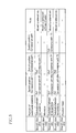
- FIG. 5 is a table to illustrate differences in the discharge operation of recording paper by switching of branch claws of FIG. 4 in an organized manner.
- FIG. 6 is a flowchart that shows the control of discharging recording paper performed by the printing apparatus of FIG. 1 .
- FIG. 7 is a flowchart that shows a process performed after the process of FIG. 6 .
- FIG. 1 is a cross-sectional view that shows a printing apparatus according to one embodiment of the present invention.
- the printing apparatus 100 is a digital multifunctional peripheral (MFP) that selectively executes a copy mode, a print mode, a scan mode and a fax mode, and acquires image data read out from an original document or image data received from an external device, and forms the monochrome image represented by the image data on recording paper.
- This printing apparatus 100 is configured mainly of a document conveying unit (ADF) 101 , an image reading unit 102 , a print processing unit 103 , a recording paper conveying unit 104 , and a feeding unit 105 .
- ADF document conveying unit
- a CIS (contact image sensor) 13 is provided on the document reading window 102 a .
- the CIS 13 repeatedly reads the image on the back of an original document in the main scanning direction while the original document passes through the document reading window 102 a , and outputs image data representing the image on the back of the original document.
- the image reading unit 102 exposes the surface of the original document with a lamp of a first scanning unit 15 , light reflected at the surface of the original document is guided to an imaging lens 17 by mirrors of first and second scanning units 15 and 16 , and the image on the surface of the original document is imaged on a CCD (charge coupled device) 18 by the imaging lens 17 .
- the CCD 18 repeatedly reads the image on the surface of the original document in the main scanning direction, and outputs image data representing the image on the surface of the original document.
- the first and second scanning units 15 and 16 are moved while maintaining a predetermined speed relationship between them, the surface of the original document on the glass platen is exposed by the first scanning unit 15 , light reflected at the surface of the original document is guided to the imaging lens 17 by the first and second scanning units 15 and 16 , and the image on the original document surface is imaged on the CCD 18 by the imaging lens 17 .
- the image data outputted from the CIS 13 or the CCD 18 is subjected to various kinds of image processing by a control circuit such as a microcomputer, and then is outputted to the print processing unit 103 .
- the print processing unit 103 is a unit that records the original represented by the image data on recording paper, and includes a photosensitive drum 21 , a charging unit 22 , an optical write unit 23 , a developing unit 24 , a transfer unit 25 , a cleaning unit 26 , a fixing apparatus 27 , and the like.
- the photosensitive drum 21 is an organic photoreceptor having a surface layer made of an organic photoconductive material. As is rotated in one direction, the surface is cleaned by the cleaning unit 26 , after which the surface is uniformly charged by the charging unit 22 .
- the charging unit 22 may be a charger type, or a roller type or brush type that contacts the photosensitive drum 21 .
- the optical write unit 23 is a two-beam writing unit that includes two laser irradiation units 28 a and 28 b so as to cope with a high speed printing process, and reduces the burden caused by increasing the speed of the irradiation timing.
- optical write unit 23 it is also possible to use, instead of the laser scanning unit, an EL writing head or LED writing head in which light-emitting elements are arranged in an array.
- the developing unit 24 supplies toner to the surface of the photosensitive drum 21 , develops the electrostatic latent image, and forms a toner image (also called a visible image) on the surface of the photosensitive drum 21 .
- the transfer unit 25 transfers the toner image on the surface of the photosensitive drum 21 to the recording paper conveyed by the recording paper conveying unit 104 .
- the fixing apparatus 27 heats and applies pressure to the recording paper to fix the toner image on the recording paper. After that, the recording paper is further conveyed by the recording paper conveying unit 104 to the discharge tray 47 where the recording paper is discharged.
- the cleaning unit 26 removes and collects the residual toner from the surface of the photosensitive drum 21 after the development and transfer.
- the transfer unit 25 includes a transfer belt 31 , a drive roller 32 , an idler roller 33 , an electrically conductive elastic roller 34 , and the like.
- the transfer belt 31 is tensioned by the rollers 32 to 34 and other rollers so that the belt can be moved in a rotating manner.
- the transfer belt 31 has a predetermined resistance value (e.g., 1 ⁇ 10 9 to 1 ⁇ 10 13 ⁇ /cm), and conveys the recording paper placed on its surface.
- the electrically conductive elastic roller 34 is pressed against the surface of the photosensitive drum 21 with the transfer belt 31 therebetween, and pushes the recording paper on the transfer belt 31 against the surface of the photosensitive drum 21 .
- a transfer electric field having the polarity opposite to that of the electric charge of the toner image on the surface of the photosensitive drum 21 is applied to the electrically conductive elastic roller 34 , and the toner image on the surface of the photosensitive drum 21 is transferred to the recording paper on the transfer belt 31 by this transfer electric field of opposite polarity.
- the toner image has a charge of negative ( ⁇ ) polarity
- the polarity of the transfer electric field applied to the electrically conductive elastic roller 34 is positive (+).
- the fixing apparatus 27 includes a heat roller 35 and a pressure roller 36 .
- the contact area also called a “nip area”
- the unfixed toner image on the recording paper is heated, fused and pressed to fix the toner image on the recording paper while the recording paper is conveyed by the rollers 35 and 36 .
- the recording paper conveying unit 104 includes a plurality of pairs of conveying rollers 41 , a pair of registration rollers 42 a , a pair of pre-registration rollers 42 b , a recording paper conveyance path 43 , reverse conveyance paths 44 a and 44 b , a plurality of branch claws 45 , a pair of discharge rollers 46 , and the like that convey the recording paper.
- the stopping and rotation of the registration rollers 42 a is performed by switching on/off the clutch between the registration rollers 42 a and a drive shaft, or by switching on/off a motor which is the driving source of the registration rollers 42 a.
- the branch claws 45 are selectively switched to guide the recording paper from the recording paper conveyance path 43 to the reverse conveyance path 44 b .
- the conveyance of the recording paper is stopped temporarily, and the branch claws 45 are again selectively switched to guide the recording paper from the reverse conveyance path 44 b to the reverse conveyance path 44 a to turn over the recording paper, and then the recording paper is returned to the registration rollers 42 a of the recording paper conveyance path 43 through the reverse conveyance path 44 a.
- the conveyance of recording paper as described above is called switchback conveyance, with which the recording paper is turned over, and at the same time, the leading edge and the trailing edge of the recording paper are also changed. Accordingly, when the recording paper is turned over and returned, the trailing edge of the recording paper abuts against the registration rollers 42 a , and is brought parallel to the registration rollers 42 a .
- the recording paper is conveyed, with its trailing edge forward, to the transfer unit 25 of the print processing unit 103 by the registration rollers 42 a , and printing is carried out on the other side of the recording paper, the toner image on the other side of the recording paper is fixed by the fixing apparatus 27 , and then the recording paper is conveyed to the discharge tray 47 .
- the feeding unit 105 includes a plurality of paper feed cassettes 48 .
- the paper feed cassettes 48 are trays for storing recording papers of various sizes, and are provided in the lower portion of the printing apparatus 100 .
- Each paper feed cassette 48 has a pickup roller 65 or the like that draws out the recording paper sheet by sheet, and sends the drawn sheets of recording paper to the recording paper conveyance path 43 of the recording paper conveying unit 104 .
- each paper feed cassette 48 is configured to have a capacity for holding 500 to 1500 sheets of recording paper of a standard size.
- the discharge tray 47 is disposed on the side of the apparatus located on the left in FIG. 1 .
- an apparatus for post-processing stapleling, punching, etc.
- the discharged recording paper or a plurality of discharge trays can be disposed optionally.
- the printing speed is increased, improving the ease of use.
- the conveying speed of the recording paper is set to 100 sheets/min (processing speed: 450 to 600 mm/sec).
- FIG. 2 is a block diagram that schematically shows a configuration of the printing apparatus 100 of FIG. 1 .
- This printing apparatus 100 includes, as shown in FIG. 1 , the document conveying unit 101 , the image reading unit 102 , the print processing unit 103 , the recording paper conveying unit 104 , and the feeding unit 105 , and further includes an information processing unit 1 , an image processing unit (ICU) 2 that edits, stores and outputs inputted image data, a network communication unit 4 that performs data communication via a network, a management unit 5 that stores and manages the control information, settings information and the like of the entire apparatus, and a control unit 6 that controls the entire apparatus.
- ICU image processing unit
- the image processing unit 2 has a hard disk drive and a memory that store image data.
- the image processing unit 2 acquires image data from the image reading unit 102 , or acquires image data received by the network communication unit 4 from an external source via a network, and stores the image data in the memory after performing an image process, or outputs image data read out from the memory to the print processing unit 103 , or sends image data read out from the memory via the network communication unit 4 .
- the information processing unit 1 includes an operation unit 51 for input operation, a display unit 52 that displays operation screens, an interface unit 53 that performs communication with a portable terminal device such as a USB device or IC card, an authentication unit 54 that authenticates inputted authentication information, a memory 55 that stores information such as authentication information, and a control unit 56 that processes the inputted operation information and authentication information.
- the communication performed by the interface unit 53 is not limited to wired communication, and may be wireless communication.
- the original document is conveyed by the document conveying unit 101 , and the original image of the original document is read out by the image reading unit 102 , the image data is transmitted from the image reading unit 102 to the image processing unit 2 where an image process, such as color correction and density correction, is performed on the image data by the image processing unit 2 , and the image data is rasterized.
- the rasterized image data is provided to the print processing unit 103 where the original image represented by the image data is recorded on recording paper by the print processing unit 103 .
- an instruction to select the scan mode is entered by an input operation through an operation key of the operation unit 51 or a display button on the screen, and then the start button (operation key) is depressed.
- the start button operation key
- the original document is conveyed by the document conveying unit 101 , and the image of the original document is read out by the image reading unit 102 , the image data is transmitted from the image reading unit 102 to the image processing unit 2 where image processing is performed on the image data by the image processing unit 2 , and the image data is stored in the memory.
- an instruction to select the fax mode is entered by an input operation through an operation key of the operation unit 51 or a display button on the screen, and then the start button (operation key) is depressed.
- the start button operation key
- the original document is conveyed by the document conveying unit 101
- the image of the original document is read out by the image reading unit 102
- the image data is transmitted from the image reading unit 102 to the image processing unit 2 where image processing is performed on the image data by the image processing unit 2
- the image is transmitted from the image processing unit 2 to the network communication unit 4 where the image data is encoded and then sent by the network communication unit 4 .
- the printing apparatus 100 has a plurality of paper feed cassettes 48 , and recording paper of a desired size can be stocked in each paper feed cassette 48 .
- this paper feed cassette 48 a plurality of sheets of recording paper are placed on the recording paper placement plate 64 , in the inner space surrounded by the trailing edge holding plate 61 , the leading edge alignment members 62 and the side regulating plates 63 .
- a configuration is formed in which the leading edge alignment members 62 are moved in lateral direction in a symmetrical manner, and at the same time, the side regulating plates 63 also are moved side to side in a symmetrical manner, so as to prevent the center position of the recording paper from deviating from the center position of the paper feed cassette 48 .
- the pickup roller 65 (shown in FIG. 1 ) of the printing apparatus 100 is pressed against the surface of the uppermost sheet of the recording paper in the paper feed cassette 48 , and is rotatively driven. This recording paper sheet is drawn in the rotating direction of the pickup roller 65 and conveyed to the recording paper conveyance path 43 .
- each paper feed cassette 48 Because recording paper of different sizes can be stocked in each paper feed cassette 48 , it is necessary to identify which paper feed cassette 48 contains which size. To this end, the size of recording paper contained in each paper feed cassette 48 is inputted/instructed by an input operation through an operation key of the operation unit 51 or a display button on the screen and the sizes of the recording papers contained in the paper feed cassettes are stored 48 in the memory of the control unit 6 .
- the control unit 6 determines the size of recording paper according to the printing conditions of a print job, and selects the paper feed cassette 48 containing the recording paper of the determined size. Then, the control unit 6 controls the driving of the pick up roller 65 of the selected paper feed cassette 48 or the like, draws the recording paper from the paper feed cassette 48 , and conveys and feeds the recording paper to the recording paper conveyance path 43 . Further, the control unit 6 controls the driving of the conveying rollers 41 , the registration rollers 42 a and the pre-registration rollers 42 b of the recording paper conveyance path 43 and the like to convey the recording paper.
- double-sided printing on recording paper is performed by switching between the face-up discharge and the face-down discharge, or turning over the recording paper.
- the face-up discharge, the face-down discharge, and the double-sided printing on recording paper are performed, after recording paper has passed through the fixing apparatus 27 , by selectively switching the branch claws 45 to deliver or retrieve recording paper to and from the recording paper conveyance path 43 and the reverse conveyance paths 44 a and 44 b.
- FIG. 4 is an enlarged view of the recording paper conveyance path 43 , the reverse conveyance paths 44 a and 44 b , and the like that are located downstream of the fixing apparatus 27 . Note that, in FIG. 4 , reference numerals 45 A to 45 E are assigned to the branch claws 45 to distinguish each branch claw.
- the branch claw 45 A pivotally supported by its pivot 45 a is rotated about the pivot 45 a , and is positioned in either of two positions Pa 1 and Pa 2 shown by a solid line and a long-short-short dashed line, respectively.
- the branch claw 45 A is positioned in the position Pa 1 shown by the solid line, the recording paper from the fixing apparatus 27 passes through the recording paper conveyance path 43 and through the discharge rollers 46 , and is discharged to the discharge tray 47 .
- the branch claw 45 A is positioned in the position Pa 2 shown by the long-short-short dashed line, the recording paper is guided from the recording paper conveyance path 43 to the intermediate conveyance path 71 .
- the branch claw 45 B is pivotally supported by its pivot 45 b , and is elastically supported by a spring (not shown in the drawings).
- a spring not shown in the drawings.
- the branch claw 45 C which is pivotally supported by its pivot 45 c , is rotated about the pivot 45 c , and is positioned in any one of three positions Pc 1 , Pc 2 , Pc 3 shown by a solid line, a long-short-short dashed line and a dotted line, respectively.
- the branch claw 45 C is positioned in the position Pc 1 shown by the solid line, the recording paper from the intermediate conveyance path 71 is guided to the reverse conveyance path 44 a .
- the branch claw 45 C is positioned in the position Pc 2 shown by the long-short-short dashed line, the recording paper from the intermediate conveyance path 71 is guided to the intermediate conveyance path 72 .
- the branch claw 45 C is positioned in the position Pc 3 shown by the dotted line, the recording paper conveyed in the opposite direction from the reverse conveyance path 44 a is guided to the intermediate conveyance path 73 .
- the branch claw 45 D which is pivotally supported by its pivot 45 d , is rotated about the pivot 45 d , and is positioned in either of two positions Pd 1 , Pd 2 shown by a long-short-short dashed line and a solid line, respectively.
- the branch claw 45 D is positioned in the position Pd 2 shown by the solid line, the recording paper conveyed from the intermediate conveyance path 72 is guided to the reverse conveyance path 44 b .
- the branch claw 45 D is positioned in the position Pd 1 shown by the long-short-short dashed line, the recording paper conveyed in the opposite direction from the reverse conveyance path 44 b is guided to the reverse conveyance path 44 a.
- the branch claw 45 E is fixed.
- the switching operation of the branch claws 45 A to 45 D is performed by configuring the branch claws to be rotatable by a driving source such as a motor or solenoid, and letting the control unit 6 control the driving of the driving sources of the branch claws 45 A to 45 D.
- the face-up discharge, the face-down discharge and the operation of turning over the recording paper can be performed selectively.
- the branch claw 45 A is positioned in the position Pa 1 shown by the solid line by the control unit 6 .
- the recording paper from the fixing apparatus 27 passes through the recording paper conveyance path 43 and through the discharge rollers 46 , and is discharged to the discharge tray 47 .
- the recording paper is discharged to the discharge tray 47 with the printed surface facing upward.
- the branch claw 45 A is positioned in the position Pa 2 shown by the long-short-short dashed line, and the branch claw 45 C is positioned in the position Pc 1 shown by the solid line by the control unit 6 .
- the recording paper is guided from the recording paper conveyance path 43 through the intermediate conveyance path 71 to the reverse conveyance path 44 a , and the recording paper is conveyed by the conveying rollers 41 a .
- the printed surface of the recording paper is faced downward.
- the conveying rollers 41 a are stopped and reversely driven by the control unit 6 , and the branch claw 45 C is positioned in the position Pc 3 shown by the dotted line. Consequently, the recording paper is conveyed in the opposite direction from the reverse conveyance path 44 a , guided to the intermediate conveyance path 73 and through the discharge rollers 46 , and discharged to the discharge tray 47 . Through this, the printed surface of the recording paper is faced downward, and the leading edge and the trailing edge of the recording paper are reversed, and after that, the recording paper is discharged to the discharge tray 47 .
- the branch claw 45 A is positioned in the position Pa 2 shown by the long-short-short dashed line, and the branch claw 45 C is positioned in the position Pc 3 shown by the dotted line, and the branch claw 45 D is position in the position Pd 2 shown by the solid line by the control unit 6 .
- the recording paper is guided from the recording paper conveyance path 43 through the intermediate conveyance path 71 to the reverse conveyance path 44 b , and the recording paper is conveyed by the conveying rollers 41 b .
- the printed surface of the recording paper faces downward.
- the conveying rollers 41 b are stopped and reversely driven by the control unit 6 , and the branch claw 45 D is positioned in the position Pd 1 shown by the long-short-short dashed line. Consequently, the recording paper is conveyed in the opposite direction from the reverse conveyance path 44 b to the reverse conveyance path 44 a .
- the recording paper is returned through the reverse conveyance path 44 a to the registration rollers 42 a , after which the recording paper is conveyed, with its trailing edge forward, to the transfer unit 25 of the print processing unit 103 where printing is carried out on the back of the recording paper, and the toner image on the back of the recording paper is fixed by the fixing apparatus 27 , and then the recording paper is returned to the branch claw 45 A.
- the back side of the recording paper is faced upward, and discharged to the discharge tray 47 by the operation of face-up discharge described above, or the front side of the recording paper is faced upward, and discharged by the operation of face-down discharge described above.
- FIG. 5 shows a table to illustrate differences in the discharge operation of recording paper by switching of the branch claws in an organized manner.
- recording paper is drawn and conveyed from a paper feed cassette 48 by the control unit 6 , and the face-up discharge, the face-down discharge, or the double-sided printing on the recording paper is selectively performed.
- a mistake may be made in inputting/instructing the paper size.
- recording paper of a standard size of A4 is loaded in a paper feed cassette 48
- a standard size of A3 may be mistakenly inputted/instructed.
- the A4 size used in Japan is different from the letter size or legal size used in the United States, but the difference is very slight. For this reason, the size may be misjudged, and the misjudged size may be inputted/instructed.
- A4 size is 210 mm ⁇ 297 mm
- letter size is 215.9 mm ⁇ 279.4 mm
- legal size is 215.9 mm ⁇ 355.6 mm.
- the paper feed cassette 48 feeds recording paper having a size different from the size of the printing conditions, resulting in defective printouts.
- the operation is performed based on the size of printing conditions. If the recording paper is shorter than the size of printing conditions, the trailing edge of the recording paper passes through the branch claw 45 E, and when the conveying rollers 41 a are stopped and reversely driven, the recording paper is guided to the reverse conveyance path 44 b rather than the intermediate conveyance path 73 , which causes a conveyance failure or jam of recording paper. Conversely, if the recording paper is longer than the size of printing conditions, the trailing edge of the recording paper cannot pass through the branch claw 45 B, and when the conveying rollers 41 are stopped and reversely driven, the recording paper is returned to the initial position, which causes a conveyance failure or jam of recording paper.
- sensors that detect the position of recording paper or the like are disposed at various locations in the recording paper conveyance path 43 and the reverse conveyance paths 44 a and 44 b , and a conveyance error or the like is detected by detecting the position of recording paper by the sensors, but if the size of recording paper is different from that of printing conditions, the timing when each sensor detects the leading edge or trailing edge of the recording paper deviates from the detection timing specified based on the size of printing conditions, this deviation is mistakenly determined as a conveyance error of recording paper, and the printing apparatus 100 stops.
- the size of the recording paper supplied is detected, and the detected size of the recording paper is compared with the size of recording paper set by the print conditions of the print job, and when the two sizes are different, the period of time until the recording paper is discharged to the discharge tray 47 is shortened to the minimum.
- the conveyance path of the recording paper is shortened to the minimum. More specifically, the face-down discharge or the turning over of the recording paper is stopped, and only the face-up discharge and single-sided printing are performed.
- the size of recording paper is detected based on the detection output of a recording paper detection sensor 74 located near the pre-registration rollers 42 b .
- the detection output of the recording paper detection sensor 74 changes when the leading edge and trailing edge of the recording paper pass therethrough.
- the control unit 6 controls the conveying speed of the recording paper conveyed by the recording paper conveying unit 104 in accordance with the printing conditions of the print job, the conveying speed is already known.
- the control unit 6 measures the time from the timing when the leading edge of recording paper is detected to the timing when the trailing edge is detected based on the detection output of the recording paper detection sensor 74 , and determines the length of the recording paper based on the measured time and the conveying speed.
- the control unit 6 determines the standard size that corresponds to the length of the recording paper. For example, the lengths of various standard sizes are stored, the standard size having the length closest to the length of the recording paper determined by detection is selected, and the standard size for the recording paper is identified.
- the control unit 6 compares the size of the first sheet of recording paper with the size of recording paper set by the print conditions of the print job.
- a single-sided printing process is performed on the first sheet of recording paper, and the face-up discharge is set to discharge the sheet in the shortest time.
- the reason why the printing process is performed is that, at the time when it is determined that the sizes are different, in other words, at the time immediately after the trailing edge of recording paper is detected by the recording paper detection sensor 74 , the development of the latent image on the surface of the photosensitive drum 21 or the like has already been performed, so the transfer of the toner image on the surface of the photosensitive drum 21 and the fixing of the toner image on the surface of the recording paper are necessary.
- preliminary paper feeding has already been performed from the paper feed cassette 48 , and the second and subsequent sheets of recording paper have already been drawn or are being drawn from the paper feed cassette 48 . Because the preliminarily fed sheets of recording paper have the same size as that of the first sheet, the face-up discharge is set also for the preliminarily fed sheets of recording paper to discharge the sheets in the shortest time.
- the development of the latent image on the surface of the photosensitive drum 21 or the like may have already been started or may not have started yet, so whether or not to perform the transfer of the toner image on the surface of the photosensitive drum 21 or the fixing of the toner image on the surface of the recording paper is determined.
- the size of the first sheet of recording paper is different from the size of recording paper set by the print conditions of a print job
- a single-sided printing process is performed, and the face-up discharge is performed to discharge the sheet in the shortest time.
- the preliminarily fed recording paper whether or not a single-sided printing process has already been started is checked, and only the single-sided printing process that has already been started is performed, and the face-up discharge is performed to discharge the paper in the shortest time.
- the recording paper having a size different from that set by the print conditions of a print job is discharged, and the print job is terminated forcibly in the shortest time so as to execute the next print job. Consequently, the next print job can be executed with little delay, so a plurality of print jobs that follow can be executed.
- a single-sided printing process and face-up discharge are performed for the first sheet of recording paper.
- the recording paper preliminary fed from the paper feed cassette 48 only the single-sided printing process that has already been started is performed, and this print job is terminated forcibly in the shortest time. Then, the next print job is started.
- control unit 6 displays that fact on the display unit 52 . Consequently, the user can perform an appropriate process based on this indication such as discarding of the recording paper of this print job having been discharged, or a retry of this print job at a later time.
- the number of sheets of recording paper that are preliminary fed from a paper feed cassette 48 is determined according to the conveying distance from the paper feed cassette 48 to the pre-registration rollers 42 b . As the conveying distance increases, the number increases. Accordingly, as the conveying distance increases, the number of sheets of recording paper on which the face-up discharge is performed is increased.
- step S 201 when a print job is generated while in the copy mode, print mode or the like, image data is rasterized by the image processing unit 2 (step S 201 ), this image data is transmitted from the image processing unit 2 to the print processing unit 103 together with the print conditions (step S 202 ), and a printing process, that is, the formation of an electrostatic latent image on the surface of the photosensitive drum 21 and the development of the electrostatic latent image, are started by the print processing unit 103 (step S 203 ).
- the paper feed cassette 48 containing the recording paper of the size set by the print conditions is selected from the paper feed cassettes 48 of the feeding unit 105 , and the first sheet of the recording paper is fed from the selected paper feed cassette 48 (step S 204 ).
- the control unit 6 monitors the detection output of the recording paper detection sensor 74 , and determines the timing when the leading edge of the recording paper is detected (step S 205 ). After the leading edge of the recording paper abuts against the registration rollers 42 a and is brought parallel to the registration rollers 42 a , the registration rollers 42 a are started to rotate, and the recording paper is conveyed to the print processing unit 103 (step S 206 ).
- the control unit 6 monitors the detection output of the recording paper detection sensor 74 , waits for the timing when the trailing edge of the first sheet of the recording paper is detected (step S 207 ), determines the timing when the trailing edge of the recording paper is detected (Yes in step S 207 ), determines the time length from the timing when the leading edge of the first sheet of the recording paper is detected to the timing when the trailing edge thereof is detected, and the length of the recording paper based on the conveying speed, and determines the size that corresponds to the length of the recording paper (step S 208 ). Further, the control unit 6 determines whether or not the determined size of the first sheet of the recording paper matches the size of recording paper set by the print conditions (step S 209 ).
- step S 209 If the size of the first sheet of the recording paper matches the size of the print conditions (Yes in step S 209 ), the control unit 6 performs a regular printing process according to the print conditions such as single-sided printing/double-sided printing, the number of print copies, print density (step S 210 ). After the print job is completed (Yes in step S 211 ), the control unit 6 returns to the state of waiting for the next print job.
- the print conditions such as single-sided printing/double-sided printing, the number of print copies, print density
- step S 209 If the size of the first sheet of the recording paper does not match the size of the print conditions (No in step S 209 ), the control unit 6 performs, without terminating the print job (step S 212 ), a single-sided printing process on the first sheet of the recording paper, and sets the face-up discharge to discharge the sheet in the shortest time (steps S 213 and S 214 ).
- control unit 6 determines whether or not there is subsequent printing on the second and subsequent sheets of the recording paper based on the print conditions (the number of print sheets or the number of print copies) (step S 215 ). If there is no subsequent printing on the second and subsequent sheets of the recording paper (No in step S 215 ), the control unit 6 terminates the print job immediately, outputs a signal that indicates the completion of printing to the image processing unit 2 (step S 216 ), and returns to the state of waiting for the next print job.
- step S 215 the control unit 6 determines whether or not there are second and subsequent sheets of the recording paper that have already been drawn or are being drawn from the paper feed cassette 48 , in other words, whether or not there is paper preliminary fed from the paper feed cassette 48 (step S 217 ). If there is no second and subsequent sheets of the recording paper that are preliminary fed (No in step S 217 ), the control unit 6 terminates the print job immediately, outputs a signal that indicates the completion of printing to the image processing unit 2 (step S 218 ), and returns to the state of waiting for the next print job.
- the print job is terminated forcibly, but because the signal indicating the completion of printing is outputted to the image processing unit 2 , the next print job is executed immediately.
- steps S 219 and S 220 are performed for these sheets, and the feeding of additional sheets of the recording paper from the paper feed cassette 48 is stopped.
- control unit 6 determines whether or not the printing process of the print processing unit 103 , such as the formation of an electrostatic latent image on the surface of the photosensitive drum 21 and the development of the electrostatic latent image, has been started for each of the second and subsequent sheets of recording paper (step S 219 ). If the printing process has been started (No in step S 219 ), the process returns to steps S 213 and S 214 where a single-sided printing process is performed, and the face-up discharge is set to discharge the sheet in the shortest time. Because the recording paper is discharged after the toner image on the surface of the photosensitive drum 21 is transferred to the recording paper. A large amount of unnecessary toner does not remain on the surface of the photosensitive drum 21 .
- step S 219 If the printing process of the print processing unit 103 has not been started (Yes in step S 219 ), without performing the printing process on the recording paper (step S 220 ), the process returns to step S 214 , and the face-up discharge is set to discharge the recording paper in the shortest time.
- the second and subsequent sheets of recording paper that are preliminary fed from the paper feed cassette 48 are discharged face-up after a single-sided printing process is performed, or are discharged face-up without a printing process. After that, a signal that indicates the completion of printing is outputted to the image processing unit 2 , and the next print job is executed immediately.
- the recording paper when the size of recording paper does not match the size of print conditions, the recording paper is discharged in the shortest time, making it unlikely for a conveyance failure or jam of recording paper to occur, and preventing the stopping of print jobs resulting from these causes. Further, because a signal that indicates the completion of printing is outputted from the control unit 6 to the image processing unit 2 after the recording paper is discharged in the shortest time, it is possible to immediately transmit the next print job from the image processing unit 2 to the print processing unit 103 , which allows a plurality of print jobs to be processed continuously without interruption. Accordingly, a continuous high speed printing process can be maintained.
- the present invention is not limited to the embodiment given above, and can be modified in various ways.
- the second and subsequent sheets of recording paper and the recording paper that are preliminary fed are discharged in the shortest time, and a signal that indicates the completion of printing is outputted from the control unit 6 to the image processing unit 2 .
- the print job when the size of recording paper does not match the size of the print conditions, not only the recording paper that are preliminary fed, but also all the sheets of recording paper whose number has been set by the print conditions of the print job may be discharged in the shortest time. In this case also, it is possible to execute the next print job without being held for a long time, achieving a high speed printing process.
- the timing of feeding the next sheet of the recording paper from the paper feed cassette 48 may be delayed, or the feeding of the next sheet of the recording paper from the paper feed cassette 48 may be started after the detection of the trailing edge of the recording paper by the recording paper detection sensor 74 has been confirmed. Because the conveyance interval of recording paper is set and controlled based on the size of recording paper set by a print job, if the length of recording paper is longer than that of recording paper set by the print job, the actual conveyance interval of recording paper is shortened.
- the timing of feeding the next sheet of recording paper may be delayed, or the feeding of the next sheet of recording paper from the paper feed cassette 48 may be started after the detection of the trailing edge of recording paper has been confirmed, so as to prevent the actual conveyance interval of recording paper from shortening. This prevents the sheets of recording paper from overlapping, or eliminates a jam of recording paper.
Landscapes
- Physics & Mathematics (AREA)
- General Physics & Mathematics (AREA)
- Engineering & Computer Science (AREA)
- Microelectronics & Electronic Packaging (AREA)
- Accessory Devices And Overall Control Thereof (AREA)
- Control Or Security For Electrophotography (AREA)
- Facsimiles In General (AREA)
Applications Claiming Priority (2)
| Application Number | Priority Date | Filing Date | Title |
|---|---|---|---|
| JP2007101832A JP4443584B2 (ja) | 2007-04-09 | 2007-04-09 | 印刷装置 |
| JP2007-101832 | 2007-04-09 |
Publications (2)
| Publication Number | Publication Date |
|---|---|
| US20080246977A1 US20080246977A1 (en) | 2008-10-09 |
| US8072619B2 true US8072619B2 (en) | 2011-12-06 |
Family
ID=39826615
Family Applications (1)
| Application Number | Title | Priority Date | Filing Date |
|---|---|---|---|
| US12/082,314 Expired - Fee Related US8072619B2 (en) | 2007-04-09 | 2008-04-09 | Printing apparatus and method for controlling the same |
Country Status (3)
| Country | Link |
|---|---|
| US (1) | US8072619B2 (zh) |
| JP (1) | JP4443584B2 (zh) |
| CN (1) | CN101286023B (zh) |
Cited By (2)
| Publication number | Priority date | Publication date | Assignee | Title |
|---|---|---|---|---|
| US20100239344A1 (en) * | 2009-03-17 | 2010-09-23 | Yasumasa Mihara | Image forming apparatus, image forming system, and computer program product |
| US20190023028A1 (en) * | 2017-07-24 | 2019-01-24 | Toshiba Tec Kabushiki Kaisha | Label printer |
Families Citing this family (11)
| Publication number | Priority date | Publication date | Assignee | Title |
|---|---|---|---|---|
| JP2010111062A (ja) * | 2008-11-07 | 2010-05-20 | Fuji Xerox Co Ltd | 画像形成システムおよびプログラム |
| JP2010184785A (ja) * | 2009-02-12 | 2010-08-26 | Fuji Xerox Co Ltd | 搬送装置、画像読取装置、及びプログラム |
| JP5243462B2 (ja) * | 2010-01-18 | 2013-07-24 | 京セラドキュメントソリューションズ株式会社 | 画像形成装置 |
| CN102207699B (zh) * | 2010-03-29 | 2015-05-20 | 株式会社东芝 | 图像形成装置、图像形成装置的薄片输送方法 |
| JP5789117B2 (ja) * | 2011-04-12 | 2015-10-07 | 理想科学工業株式会社 | 画像形成装置 |
| JP6124510B2 (ja) * | 2012-05-07 | 2017-05-10 | キヤノン株式会社 | 画像形成装置 |
| US9342018B2 (en) * | 2013-05-17 | 2016-05-17 | Oki Data Corporation | Image forming apparatus with automatic size determination |
| US9964907B2 (en) * | 2013-11-29 | 2018-05-08 | Canon Kabushiki Kaisha | Image forming apparatus and image forming system |
| JP6349728B2 (ja) * | 2013-12-27 | 2018-07-04 | ブラザー工業株式会社 | 印刷装置 |
| US10324410B2 (en) * | 2016-04-27 | 2019-06-18 | Kyocera Document Solutions Inc. | Image forming apparatus |
| CN114987070B (zh) * | 2022-06-27 | 2023-08-22 | 武汉中谷联创光电科技股份有限公司 | 一种打印尺寸校准方法、装置、打印设备及存储介质 |
Citations (11)
| Publication number | Priority date | Publication date | Assignee | Title |
|---|---|---|---|---|
| JPH06156804A (ja) | 1992-11-16 | 1994-06-03 | Ricoh Co Ltd | 画像形成装置 |
| JPH08282030A (ja) | 1995-04-11 | 1996-10-29 | Canon Inc | 画像形成装置 |
| JPH1031394A (ja) | 1996-07-16 | 1998-02-03 | Canon Inc | 画像形成装置 |
| JPH11301079A (ja) | 1998-04-27 | 1999-11-02 | Canon Inc | 印刷方法、印刷システムおよび記録媒体 |
| JP2000330741A (ja) | 1999-05-20 | 2000-11-30 | Fuji Xerox Co Ltd | 画像形成装置の制御方法および装置 |
| JP2001213031A (ja) | 2000-02-02 | 2001-08-07 | Casio Electronics Co Ltd | 印刷装置 |
| JP2001315997A (ja) | 2000-05-01 | 2001-11-13 | Ricoh Co Ltd | 画像形成装置 |
| US20020131787A1 (en) * | 2001-03-15 | 2002-09-19 | Canon Kabushiki Kaisha | Image forming apparatus, control method thereof and control program therefor |
| US20030025937A1 (en) * | 2001-07-31 | 2003-02-06 | Hewlett Packard Company | Media loading in printing systems |
| JP2004338834A (ja) | 2003-05-13 | 2004-12-02 | Sharp Corp | シート搬送装置 |
| US20080180711A1 (en) * | 2007-01-29 | 2008-07-31 | Canon Kabushiki Kaisha | Information processing apparatus and information processing method |
-
2007
- 2007-04-09 JP JP2007101832A patent/JP4443584B2/ja active Active
-
2008
- 2008-04-09 CN CN2008100916205A patent/CN101286023B/zh not_active Expired - Fee Related
- 2008-04-09 US US12/082,314 patent/US8072619B2/en not_active Expired - Fee Related
Patent Citations (11)
| Publication number | Priority date | Publication date | Assignee | Title |
|---|---|---|---|---|
| JPH06156804A (ja) | 1992-11-16 | 1994-06-03 | Ricoh Co Ltd | 画像形成装置 |
| JPH08282030A (ja) | 1995-04-11 | 1996-10-29 | Canon Inc | 画像形成装置 |
| JPH1031394A (ja) | 1996-07-16 | 1998-02-03 | Canon Inc | 画像形成装置 |
| JPH11301079A (ja) | 1998-04-27 | 1999-11-02 | Canon Inc | 印刷方法、印刷システムおよび記録媒体 |
| JP2000330741A (ja) | 1999-05-20 | 2000-11-30 | Fuji Xerox Co Ltd | 画像形成装置の制御方法および装置 |
| JP2001213031A (ja) | 2000-02-02 | 2001-08-07 | Casio Electronics Co Ltd | 印刷装置 |
| JP2001315997A (ja) | 2000-05-01 | 2001-11-13 | Ricoh Co Ltd | 画像形成装置 |
| US20020131787A1 (en) * | 2001-03-15 | 2002-09-19 | Canon Kabushiki Kaisha | Image forming apparatus, control method thereof and control program therefor |
| US20030025937A1 (en) * | 2001-07-31 | 2003-02-06 | Hewlett Packard Company | Media loading in printing systems |
| JP2004338834A (ja) | 2003-05-13 | 2004-12-02 | Sharp Corp | シート搬送装置 |
| US20080180711A1 (en) * | 2007-01-29 | 2008-07-31 | Canon Kabushiki Kaisha | Information processing apparatus and information processing method |
Cited By (3)
| Publication number | Priority date | Publication date | Assignee | Title |
|---|---|---|---|---|
| US20100239344A1 (en) * | 2009-03-17 | 2010-09-23 | Yasumasa Mihara | Image forming apparatus, image forming system, and computer program product |
| US8670703B2 (en) * | 2009-03-17 | 2014-03-11 | Ricoh Company, Limited | Image forming apparatus, image forming system, and computer program product |
| US20190023028A1 (en) * | 2017-07-24 | 2019-01-24 | Toshiba Tec Kabushiki Kaisha | Label printer |
Also Published As
| Publication number | Publication date |
|---|---|
| US20080246977A1 (en) | 2008-10-09 |
| JP4443584B2 (ja) | 2010-03-31 |
| JP2008254399A (ja) | 2008-10-23 |
| CN101286023A (zh) | 2008-10-15 |
| CN101286023B (zh) | 2010-12-01 |
Similar Documents
| Publication | Publication Date | Title |
|---|---|---|
| US8072619B2 (en) | Printing apparatus and method for controlling the same | |
| JP4669025B2 (ja) | 画像処理装置及び画像処理方法 | |
| JP2007163755A (ja) | 画像形成装置、原稿読取装置及び該装置を備える複写機 | |
| JP2010191659A (ja) | 画像処理装置 | |
| JP3810779B2 (ja) | 画像形成装置と画像形成方法 | |
| JP2023134845A (ja) | シート給送装置、画像読取装置および画像形成装置 | |
| JP2007221246A (ja) | 原稿読取り装置、及びそれを用いた画像形成装置 | |
| US20160292552A1 (en) | Image forming apparatus | |
| JP2004005559A (ja) | 画像処理システム、および画像記録方法 | |
| US20150029521A1 (en) | Printing apparatus, control method of printing apparatus, and storage medium | |
| JP2006347645A (ja) | 画像形成装置 | |
| JP3842038B2 (ja) | 画像形成装置 | |
| JP2006030407A (ja) | 画像形成装置 | |
| JP5290889B2 (ja) | 自動原稿搬送装置、画像読取装置、及び、画像形成装置 | |
| JP6384450B2 (ja) | シート積載装置及びそれを備えたシート後処理装置並びに画像形成装置 | |
| JP5663391B2 (ja) | 画像データ記憶装置、原稿読取装置及び画像形成装置 | |
| JP4310129B2 (ja) | 原稿給送装置、画像形成装置、原稿給送装置の制御方法及び画像形成装置の制御方法 | |
| JP2006085066A (ja) | 画像形成装置 | |
| JPH11327858A (ja) | 画像形成装置 | |
| US20240174472A1 (en) | Paper feeder and image forming apparatus | |
| JP2010126329A (ja) | シート排出装置及びそれを備えた画像形成装置 | |
| JP4602837B2 (ja) | 画像形成装置、プレビュー表示制御方法 | |
| JP2016159997A (ja) | 画像形成装置 | |
| JP6358147B2 (ja) | 画像形成装置 | |
| JP5767894B2 (ja) | 給送装置及び画像形成装置 |
Legal Events
| Date | Code | Title | Description |
|---|---|---|---|
| AS | Assignment |
Owner name: SHARP KABUSHIKI KAISHA, JAPAN Free format text: ASSIGNMENT OF ASSIGNORS INTEREST;ASSIGNORS:FUJII, SHUHJI;UEDA, NOBUYUKI;MURAKAMI, ASTUHIKO;REEL/FRAME:020822/0387 Effective date: 20080324 |
|
| ZAAA | Notice of allowance and fees due |
Free format text: ORIGINAL CODE: NOA |
|
| ZAAB | Notice of allowance mailed |
Free format text: ORIGINAL CODE: MN/=. |
|
| STCF | Information on status: patent grant |
Free format text: PATENTED CASE |
|
| FEPP | Fee payment procedure |
Free format text: PAYOR NUMBER ASSIGNED (ORIGINAL EVENT CODE: ASPN); ENTITY STATUS OF PATENT OWNER: LARGE ENTITY |
|
| FEPP | Fee payment procedure |
Free format text: PAYER NUMBER DE-ASSIGNED (ORIGINAL EVENT CODE: RMPN); ENTITY STATUS OF PATENT OWNER: LARGE ENTITY Free format text: PAYOR NUMBER ASSIGNED (ORIGINAL EVENT CODE: ASPN); ENTITY STATUS OF PATENT OWNER: LARGE ENTITY |
|
| FPAY | Fee payment |
Year of fee payment: 4 |
|
| MAFP | Maintenance fee payment |
Free format text: PAYMENT OF MAINTENANCE FEE, 8TH YEAR, LARGE ENTITY (ORIGINAL EVENT CODE: M1552); ENTITY STATUS OF PATENT OWNER: LARGE ENTITY Year of fee payment: 8 |
|
| FEPP | Fee payment procedure |
Free format text: MAINTENANCE FEE REMINDER MAILED (ORIGINAL EVENT CODE: REM.); ENTITY STATUS OF PATENT OWNER: LARGE ENTITY |
|
| LAPS | Lapse for failure to pay maintenance fees |
Free format text: PATENT EXPIRED FOR FAILURE TO PAY MAINTENANCE FEES (ORIGINAL EVENT CODE: EXP.); ENTITY STATUS OF PATENT OWNER: LARGE ENTITY |
|
| STCH | Information on status: patent discontinuation |
Free format text: PATENT EXPIRED DUE TO NONPAYMENT OF MAINTENANCE FEES UNDER 37 CFR 1.362 |
|
| FP | Lapsed due to failure to pay maintenance fee |
Effective date: 20231206 |