US7426883B2 - Substrate-cutting system, substrate-producing apparatus, substrate-scribing method, and substrate-cutting method - Google Patents
Substrate-cutting system, substrate-producing apparatus, substrate-scribing method, and substrate-cutting method Download PDFInfo
- Publication number
- US7426883B2 US7426883B2 US10/535,871 US53587105A US7426883B2 US 7426883 B2 US7426883 B2 US 7426883B2 US 53587105 A US53587105 A US 53587105A US 7426883 B2 US7426883 B2 US 7426883B2
- Authority
- US
- United States
- Prior art keywords
- substrate
- supporting
- scribing
- bonded mother
- substrate supporting
- Prior art date
- Legal status (The legal status is an assumption and is not a legal conclusion. Google has not performed a legal analysis and makes no representation as to the accuracy of the status listed.)
- Active, expires
Links
Images


Classifications
-
- B—PERFORMING OPERATIONS; TRANSPORTING
- B65—CONVEYING; PACKING; STORING; HANDLING THIN OR FILAMENTARY MATERIAL
- B65G—TRANSPORT OR STORAGE DEVICES, e.g. CONVEYORS FOR LOADING OR TIPPING, SHOP CONVEYOR SYSTEMS OR PNEUMATIC TUBE CONVEYORS
- B65G49/00—Conveying systems characterised by their application for specified purposes not otherwise provided for
- B65G49/05—Conveying systems characterised by their application for specified purposes not otherwise provided for for fragile or damageable materials or articles
- B65G49/06—Conveying systems characterised by their application for specified purposes not otherwise provided for for fragile or damageable materials or articles for fragile sheets, e.g. glass
- B65G49/063—Transporting devices for sheet glass
- B65G49/064—Transporting devices for sheet glass in a horizontal position
-
- B—PERFORMING OPERATIONS; TRANSPORTING
- B28—WORKING CEMENT, CLAY, OR STONE
- B28D—WORKING STONE OR STONE-LIKE MATERIALS
- B28D1/00—Working stone or stone-like materials, e.g. brick, concrete or glass, not provided for elsewhere; Machines, devices, tools therefor
- B28D1/22—Working stone or stone-like materials, e.g. brick, concrete or glass, not provided for elsewhere; Machines, devices, tools therefor by cutting, e.g. incising
- B28D1/225—Working stone or stone-like materials, e.g. brick, concrete or glass, not provided for elsewhere; Machines, devices, tools therefor by cutting, e.g. incising for scoring or breaking, e.g. tiles
- B28D1/226—Working stone or stone-like materials, e.g. brick, concrete or glass, not provided for elsewhere; Machines, devices, tools therefor by cutting, e.g. incising for scoring or breaking, e.g. tiles with plural scoring tools
-
- B—PERFORMING OPERATIONS; TRANSPORTING
- B28—WORKING CEMENT, CLAY, OR STONE
- B28D—WORKING STONE OR STONE-LIKE MATERIALS
- B28D5/00—Fine working of gems, jewels, crystals, e.g. of semiconductor material; apparatus or devices therefor
- B28D5/0005—Fine working of gems, jewels, crystals, e.g. of semiconductor material; apparatus or devices therefor by breaking, e.g. dicing
- B28D5/0011—Fine working of gems, jewels, crystals, e.g. of semiconductor material; apparatus or devices therefor by breaking, e.g. dicing with preliminary treatment, e.g. weakening by scoring
-
- B—PERFORMING OPERATIONS; TRANSPORTING
- B28—WORKING CEMENT, CLAY, OR STONE
- B28D—WORKING STONE OR STONE-LIKE MATERIALS
- B28D5/00—Fine working of gems, jewels, crystals, e.g. of semiconductor material; apparatus or devices therefor
- B28D5/0058—Accessories specially adapted for use with machines for fine working of gems, jewels, crystals, e.g. of semiconductor material
- B28D5/0082—Accessories specially adapted for use with machines for fine working of gems, jewels, crystals, e.g. of semiconductor material for supporting, holding, feeding, conveying or discharging work
-
- B—PERFORMING OPERATIONS; TRANSPORTING
- B65—CONVEYING; PACKING; STORING; HANDLING THIN OR FILAMENTARY MATERIAL
- B65G—TRANSPORT OR STORAGE DEVICES, e.g. CONVEYORS FOR LOADING OR TIPPING, SHOP CONVEYOR SYSTEMS OR PNEUMATIC TUBE CONVEYORS
- B65G49/00—Conveying systems characterised by their application for specified purposes not otherwise provided for
- B65G49/05—Conveying systems characterised by their application for specified purposes not otherwise provided for for fragile or damageable materials or articles
- B65G49/06—Conveying systems characterised by their application for specified purposes not otherwise provided for for fragile or damageable materials or articles for fragile sheets, e.g. glass
- B65G49/061—Lifting, gripping, or carrying means, for one or more sheets forming independent means of transport, e.g. suction cups, transport frames
-
- B—PERFORMING OPERATIONS; TRANSPORTING
- B65—CONVEYING; PACKING; STORING; HANDLING THIN OR FILAMENTARY MATERIAL
- B65G—TRANSPORT OR STORAGE DEVICES, e.g. CONVEYORS FOR LOADING OR TIPPING, SHOP CONVEYOR SYSTEMS OR PNEUMATIC TUBE CONVEYORS
- B65G49/00—Conveying systems characterised by their application for specified purposes not otherwise provided for
- B65G49/05—Conveying systems characterised by their application for specified purposes not otherwise provided for for fragile or damageable materials or articles
- B65G49/06—Conveying systems characterised by their application for specified purposes not otherwise provided for for fragile or damageable materials or articles for fragile sheets, e.g. glass
- B65G49/067—Sheet handling, means, e.g. manipulators, devices for turning or tilting sheet glass
-
- C—CHEMISTRY; METALLURGY
- C03—GLASS; MINERAL OR SLAG WOOL
- C03B—MANUFACTURE, SHAPING, OR SUPPLEMENTARY PROCESSES
- C03B33/00—Severing cooled glass
- C03B33/02—Cutting or splitting sheet glass or ribbons; Apparatus or machines therefor
- C03B33/023—Cutting or splitting sheet glass or ribbons; Apparatus or machines therefor the sheet or ribbon being in a horizontal position
- C03B33/027—Scoring tool holders; Driving mechanisms therefor
-
- C—CHEMISTRY; METALLURGY
- C03—GLASS; MINERAL OR SLAG WOOL
- C03B—MANUFACTURE, SHAPING, OR SUPPLEMENTARY PROCESSES
- C03B33/00—Severing cooled glass
- C03B33/02—Cutting or splitting sheet glass or ribbons; Apparatus or machines therefor
- C03B33/023—Cutting or splitting sheet glass or ribbons; Apparatus or machines therefor the sheet or ribbon being in a horizontal position
- C03B33/03—Glass cutting tables; Apparatus for transporting or handling sheet glass during the cutting or breaking operations
-
- C—CHEMISTRY; METALLURGY
- C03—GLASS; MINERAL OR SLAG WOOL
- C03B—MANUFACTURE, SHAPING, OR SUPPLEMENTARY PROCESSES
- C03B33/00—Severing cooled glass
- C03B33/09—Severing cooled glass by thermal shock
-
- B—PERFORMING OPERATIONS; TRANSPORTING
- B65—CONVEYING; PACKING; STORING; HANDLING THIN OR FILAMENTARY MATERIAL
- B65G—TRANSPORT OR STORAGE DEVICES, e.g. CONVEYORS FOR LOADING OR TIPPING, SHOP CONVEYOR SYSTEMS OR PNEUMATIC TUBE CONVEYORS
- B65G2249/00—Aspects relating to conveying systems for the manufacture of fragile sheets
- B65G2249/04—Arrangements of vacuum systems or suction cups
-
- Y—GENERAL TAGGING OF NEW TECHNOLOGICAL DEVELOPMENTS; GENERAL TAGGING OF CROSS-SECTIONAL TECHNOLOGIES SPANNING OVER SEVERAL SECTIONS OF THE IPC; TECHNICAL SUBJECTS COVERED BY FORMER USPC CROSS-REFERENCE ART COLLECTIONS [XRACs] AND DIGESTS
- Y10—TECHNICAL SUBJECTS COVERED BY FORMER USPC
- Y10T—TECHNICAL SUBJECTS COVERED BY FORMER US CLASSIFICATION
- Y10T225/00—Severing by tearing or breaking
- Y10T225/30—Breaking or tearing apparatus
- Y10T225/307—Combined with preliminary weakener or with nonbreaking cutter
- Y10T225/321—Preliminary weakener
-
- Y—GENERAL TAGGING OF NEW TECHNOLOGICAL DEVELOPMENTS; GENERAL TAGGING OF CROSS-SECTIONAL TECHNOLOGIES SPANNING OVER SEVERAL SECTIONS OF THE IPC; TECHNICAL SUBJECTS COVERED BY FORMER USPC CROSS-REFERENCE ART COLLECTIONS [XRACs] AND DIGESTS
- Y10—TECHNICAL SUBJECTS COVERED BY FORMER USPC
- Y10T—TECHNICAL SUBJECTS COVERED BY FORMER US CLASSIFICATION
- Y10T83/00—Cutting
- Y10T83/02—Other than completely through work thickness
- Y10T83/0304—Grooving
-
- Y—GENERAL TAGGING OF NEW TECHNOLOGICAL DEVELOPMENTS; GENERAL TAGGING OF CROSS-SECTIONAL TECHNOLOGIES SPANNING OVER SEVERAL SECTIONS OF THE IPC; TECHNICAL SUBJECTS COVERED BY FORMER USPC CROSS-REFERENCE ART COLLECTIONS [XRACs] AND DIGESTS
- Y10—TECHNICAL SUBJECTS COVERED BY FORMER USPC
- Y10T—TECHNICAL SUBJECTS COVERED BY FORMER US CLASSIFICATION
- Y10T83/00—Cutting
- Y10T83/02—Other than completely through work thickness
- Y10T83/0333—Scoring
- Y10T83/0341—Processes
-
- Y—GENERAL TAGGING OF NEW TECHNOLOGICAL DEVELOPMENTS; GENERAL TAGGING OF CROSS-SECTIONAL TECHNOLOGIES SPANNING OVER SEVERAL SECTIONS OF THE IPC; TECHNICAL SUBJECTS COVERED BY FORMER USPC CROSS-REFERENCE ART COLLECTIONS [XRACs] AND DIGESTS
- Y10—TECHNICAL SUBJECTS COVERED BY FORMER USPC
- Y10T—TECHNICAL SUBJECTS COVERED BY FORMER US CLASSIFICATION
- Y10T83/00—Cutting
- Y10T83/02—Other than completely through work thickness
- Y10T83/0333—Scoring
- Y10T83/0363—Plural independent scoring blades
- Y10T83/037—Rotary scoring blades
- Y10T83/0378—On opposite sides of work
-
- Y—GENERAL TAGGING OF NEW TECHNOLOGICAL DEVELOPMENTS; GENERAL TAGGING OF CROSS-SECTIONAL TECHNOLOGIES SPANNING OVER SEVERAL SECTIONS OF THE IPC; TECHNICAL SUBJECTS COVERED BY FORMER USPC CROSS-REFERENCE ART COLLECTIONS [XRACs] AND DIGESTS
- Y10—TECHNICAL SUBJECTS COVERED BY FORMER USPC
- Y10T—TECHNICAL SUBJECTS COVERED BY FORMER US CLASSIFICATION
- Y10T83/00—Cutting
- Y10T83/444—Tool engages work during dwell of intermittent workfeed
- Y10T83/4617—Work feed means modified to maintain clearance from tool
-
- Y—GENERAL TAGGING OF NEW TECHNOLOGICAL DEVELOPMENTS; GENERAL TAGGING OF CROSS-SECTIONAL TECHNOLOGIES SPANNING OVER SEVERAL SECTIONS OF THE IPC; TECHNICAL SUBJECTS COVERED BY FORMER USPC CROSS-REFERENCE ART COLLECTIONS [XRACs] AND DIGESTS
- Y10—TECHNICAL SUBJECTS COVERED BY FORMER USPC
- Y10T—TECHNICAL SUBJECTS COVERED BY FORMER US CLASSIFICATION
- Y10T83/00—Cutting
- Y10T83/647—With means to convey work relative to tool station
- Y10T83/6584—Cut made parallel to direction of and during work movement
- Y10T83/6606—Tool between laterally spaced work-conveying means
Definitions
- the present invention relates to a substrate cutting system and a substrate cutting line system used for cutting mother substrates of various materials, including mother substrates such as glass substrates used for display panels of liquid crystal display apparatuses and the like, and more particularly, a substrate cutting system, a substrate manufacturing apparatus, a substrate scribing method, and a substrate cutting method which can be preferably used for cutting bonded mother substrates formed by bonding a pair of brittle material substrates to each other.
- Display panels of the liquid crystal display apparatuses and the like are usually made of glass substrates which are brittle material substrates.
- the liquid crystal display apparatuses includes display panels formed by bonding a pair of glass substrates with an appropriate space therebetween and enclosing liquid crystal into the space.
- a process to cut out a plurality of display panels of a bonded mother substrate by cutting the bonded mother substrate which is obtained by bonding mother glass substrates is performed.
- a scribing apparatus used for cutting bonded mother substrates is disclosed in Publication for Utility Model Opposition No. 59-22101.
- FIG. 93 to a schematic view showing a structure of the scribing apparatus.
- a scribing apparatus 950 includes tables 951 for respectively putting a side edge portion of a bonded mother substrate 908 thereon. On the tables 951 , clamp members 952 for clamping the side edge portions of the bonded mother substrate 908 are attached.
- the scribing apparatus 950 includes a pair of cutter heads 953 and 954 respectively provided above and below the bonded mother substrate 908 . The cutter heads 953 and 954 oppose each other with the bonded mother substrate 908 interposed therebetween.
- a front surface and a back surface of the bonded mother substrate 908 are scribed at the same time by the pair of cutter heads 953 and 954 to form scribe lines.
- a breaking apparatus for cutting the bonded mother substrate 908 on which the scribe lines are formed is separately required. Further, for cutting the bonded mother substrate 908 by a breaking apparatus, it is necessary to reverse the bonded mother substrate 908 (to turn the substrate upside down) after cutting one of the mother substrates of the bonded mother substrate 908 for cutting another substrate. For cutting display panels out of the bonded mother substrate 908 , a complicated line system has to be established.
- the bonded mother substrate 908 is scribed from both front surface and back surface at the same time.
- the process direction is limited to one direction, and cross scribing (scribing along directions such that the scribe lines are orthogonal to each other) is impossible.
- the present invention is to solve such problems and the object thereof is to provide a substrate cutting system and a substrate cutting system which has a small foot print and a compact structure, and which can efficiently cut various types of mother substrates.
- a substrate cutting system is characterized by comprising: a hollow parallelepiped mounting structure; a clamp device attached to the mounting structure so as to clamp at least one portion of a side edge of a substrate carried into the mounting structure; a pair of substrate cutting devices for cutting the substrate from an upper surface side and a lower surface side of the substrate clamped by the clamping device; and a scribing device guide body which is movable back and forth along one side of the hollow parallelepiped mounting structure and to which the pair of substrate cutting devices are attached so as to be movable along a direction orthogonal to the moving direction.
- the present invention is further characterized by comprising a substrate supporting device for supporting the substrate clamped by the clamping device.
- the present invention is further characterized by comprising a first substrate supporting portion provided on one side in the moving direction of the scribing device guide body.
- the present invention is further characterized in that the first substrate supporting portion includes a plurality of first substrate supporting units which can move parallel along the moving direction of the scribing device guide body, the first substrate supporting units being moved so as to apart from each other as the scribing device guide body moves in one direction and being moved so as to approach each other as the scribing device guide body moves in other direction.
- the present invention is further characterized in that, in the first substrate supporting units, a plurality of first supporting belts respectively arranged along the moving direction of the scribing device guide body are supported, and the substrate is supported in a horizontal fashion by the first supporting belts by moving the first substrate supporting units so as to apart from each other.
- the present invention is further characterized by comprising first winding means for winding the first supporting belts by moving the first substrate supporting units so as to approach each other.
- the present invention is further characterized in that, in the first substrate supporting units, a substrate upward/downward moving device for lifting the substrate above the first supporting belts so that the substrate is clamped by the clamp device is provided.
- the present invention is further characterized in that the first substrate supporting portion includes a plurality of first substrate supporting units which move parallel along the moving direction of the scribing device guide body, the first substrate supporting units being moved with the scribing device guide body as the scribing device guide body moves in one direction.
- the present invention is further characterized in that the first substrate supporting units comprises a plurality of belts for supporting the substrate.
- the present invention is further characterized by comprising at least one clutch unit for selectively rotating the plurality of belts in accordance with the movement of the scribing device guide body.
- the present invention is further characterized in that the substrate supporting device further comprises second substrate supporting portion provided on the other side in the moving direction of the scribing device guide body.
- the present invention is further characterized in that the second substrate supporting portion includes a plurality of second substrate supporting units which move parallel along the moving direction of the scribing device guide body, the second substrate supporting units being moved so as to approach each other in the movement in one direction and being moved so as to apart from each other in the movement in other direction.
- the present invention is further characterized in that, in the second substrate supporting units, a plurality of second supporting belts respectively arranged along the moving direction of the scribing device guide body are supported, and the substrate is supported in a horizontal fashion by the second supporting belts by moving the second substrate supporting units so as to apart from each other.
- the present invention is further characterized by comprising second winding means for winding the second supporting belts by moving the second substrate supporting units so as to approach each other.
- the present invention is further characterized in that the second substrate supporting portion includes a plurality of second substrate supporting units which move parallel along the moving direction of the scribing device guide body, the second substrate supporting units being moved with the scribing device guide body as the scribing device guide body moves in one direction.
- the present invention is further characterized in that the second substrate supporting units comprises a plurality of belts for supporting the substrate.
- the present invention is further characterized by comprising at least one clutch unit for selectively rotating the plurality of belts in accordance with the movement of the scribing device guide body.
- the present invention is further characterized in that a or the substrate cutting devices comprises a cutter head for transmitting pressure to the substrate using a servo motor for a cutter wheel.
- the present invention is further characterized by comprising a steam unit portion for spraying steam on front and back surfaces of the substrate having scribe lines carved thereon at a or the substrate cutting devices.
- the present invention is further characterized in that the steam unit portion includes substrate drying means for drying front and back surfaces of the substrate.
- a substrate cutting system characterized by comprising a substrate carry-out device for taking out the substrate which has been cut at the steam unit portion.
- the substrate carrying device includes a carrying robot comprising: substrate holding means for holding the substrate; substrate rotation means for rotating the substrate holding means holding the substrate around a first axis vertical to the substrate; and means for rotating the substrate rotation means around a second axle which is different from the first axis vertical to the substrate held by the substrate holding means.
- the present invention is further characterized by comprising substrate inversion means for inverting the substrate carried by the substrate carrying device upside down.
- the present invention is further characterized by comprising a positioning unit portion for positioning the substrate.
- the present invention is further characterized by comprising a carrying unit for carrying the substrate scribed by the scribing device guide body to a steam unit portion.
- the present invention is further characterized by comprising removal means for removing unnecessary portion of the cut substrate.
- the present invention is further characterized in that the plurality of belts are strained between a frame on a substrate carry-in side and a frame on a substrate carry-out side, the plurality of belts sinking below the scribing device guide body or coming up from below the scribing device guide body during the first substrate supporting portion is moving.
- the present invention is further characterized in that the plurality of belts are strained between a frame on a substrate carry-in side and a frame on a substrate carry-out side, the plurality of belts sinking below the scribing device guide body or coming up from below the scribing device guide body during the second substrate supporting portion is moving.
- the present invention is further characterized in that the substrate is a bonded mother substrate formed by bonding a pair of mother substrates.
- a substrate manufacturing apparatus is characterized in that a chamfering system for chamfering end surfaces of the cut substrate is connected to the above substrate cutting system.
- the present invention is further characterized in that an inspection system for inspecting functions of the cut substrate is connected.
- a substrate scribing method for forming scribe lines on an upper surface and a lower surf ace of a substrate according to the present invention is characterized in that: scribe line formation means for forming a vertical crack along a thickness direction of the substrate oppose each other, and the scribe lines are continuously formed by the scribe formation means without being apart from the substrate.
- the present invention is further characterized in that three or more linear scribe lines are formed by the scribe line formation means, a closed curve being formed by all the scribe lines which has been formed.
- the present invention to further characterized in that the scribe line formation means form a closed curve having a rectangular shape.
- the present invention is further characterized in that the scribe line formation means is a cutter wheel tip having a disc shape and having a blade edge for rotating on a surface of the substrate in an outer periphery.
- the present invention is further characterized in that the cutter wheel tip has a plurality of protrusions formed in a blade edge in a predetermined pitch.
- the present invention is further characterized in that sub-scribe lines along at least two formed scribe lines are formed by the cutter wheel tip after at least two scribe lines are formed by the cutter wheel tip.
- the present invention is further characterized in that the sub-scribe lines are formed continuously after the at least two scribe lines formed on the substrate without separating the cutter wheel tip from a surface of the substrate.
- the present invention to further characterized in that the cutter wheel tip forms one scribe line, moves on the surface drawing a circular trace, and then, forms the other scribe line.
- the present invention is further characterized in that, when the cutter wheal tip moves on the substrate drawing a circular trace, pressure to the substrate is reduced compared to pressure to the substrate when the scribe lines are being formed.
- a substrate cutting method is characterized in that a scribing method for forming scribe lines on an upper surface and a lower surf ace of the substrate comprises the steps of: forming a main scribe line along a line to be cut on the substrate by opposing scribe line formation means for forming a vertical crack along a thickness direction of the substrate; and forming a supplementary scribe line along the main scribe line with a predetermined space apart from the formed main scribe line.
- the present invention is further characterized in that the supplementary scribe line is formed with a space of 0.5 mm to 1.0 mm apart from the main scribe line.
- the present invention is further characterized in that the main scribe line is formed by a vertical crack which extends to 80% or more of a thickness direction of the substrate from the substrate surface.
- the present invention is further characterized in that the main scribe line is formed by a vertical crack which extends to 90% or more of a thickness direction of the substrate from the substrate surface.
- the present invention is further characterized in that the main scribe line is formed by a cutter wheel having a disc shape which rotates on the substrate surface, the cutter wheel protruding outward so as to have a center portion of an outer periphery in a width direction which has a shape of letter V with an obtuse angle, a plurality of protrusions with a predetermined height being provided across the entire circumferential with a predetermined pitch in a portion having the obtuse angle.
- the present invention is further characterized in that a formation direction of main scribe line and a formation direction of supplementary scribe line by the cutter wheel are opposite to each other, and the cutter wheel continuously form the main scribe line and the supplementary scribe line in contact with the substrate surface.
- the present invention is further characterized in that the main scribe line and the supplementary scribe line are formed with an appropriate space from at least one end portion of the line to be out.
- a substrate cutting method for cutting a substrate having scribe lines formed respectively on an upper surface and a lower surface of the substrates characterized in that: the upper surface and the lower surface of the substrate are heated for cutting the substrate.
- FIG. 1 is a schematic perspective view showing an example of a substrate cutting system according to Embodiment 1 of the present invention.
- FIG. 2 is a schematic perspective view of the substrate cutting system according to Embodiment 1 of the present invention viewed from another direction.
- FIG. 3 is a perspective view of an important part of the substrate cutting system according to Embodiment 1 of the present invention.
- FIG. 4 is a perspective view for illustrating operations of a substrate supporting device of the substrate cutting system according to Embodiment 1 of the present invention.
- FIG. 5 is a cross-sectional view of an important part of the substrate cutting system according to Embodiment 1 of the present invention.
- FIG. 6 to a schematic perspective view of an important part of the substrate cutting system according to Embodiment 1 of the present invention which is enlarged.
- FIG. 7 is a schematic perspective view of another important part of the substrate cutting system according to Embodiment 1 of the present invention which is enlarged.
- FIG. 8 is a perspective view of a first substrate supporting unit provided in the substrate supporting device of the substrate cutting system according to Embodiment 1 of the present invention.
- FIG. 9 is a front view of a substrate upward/downward moving device in the first substrate supporting unit with a part thereof being broken.
- FIG. 10 is a side view showing structures of connection arms attached to at least one end portion of the first substrate supporting units 21 .
- FIG. 11 is a front view of the substrate upward/downward moving device shown in FIG. 9 with a part thereof being broken.
- FIG. 12 is a perspective view of the substrate upward/downward moving device with a part thereof being broken.
- FIG. 13 is a perspective view for showing structures of clamp device provided in the substrate cutting system.
- FIG. 14 is a perspective view for showing an operation of the clamp device.
- FIG. 15 is a side view showing an example of a cutter head provided in the substrate cutting device in the substrate cutting system according to Embodiment 1 of the present invention.
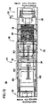
- FIG. 16 is a front view showing an important part of the cutter head.
- FIG. 17 is a front view showing another example of the cutter head provided in the substrate cutting device in the substrate cutting system according to Embodiment 1 of the present invention.
- FIG. 18 is a schematic plan view for illustrating an operation of the substrate cutting system according to Embodiment 1 of the present invention.
- FIG. 19 is a schematic plan view for illustrating an operation of the substrate cutting system according to Embodiment 1 of the present invention.
- FIG. 20 is a schematic plan view for illustrating an operation of the substrate cutting system according to Embodiment 1 of the present invention.
- FIG. 21 is a cross sectional view of a substrate for illustrating the principle of a substrate cutting method according to the present invention.
- FIG. 22 is a plan view of a substrate showing a scribe pattern for the substrate for illustrating an example of the substrate cutting method according to the present invention.
- FIG. 23 is a plan view of a substrate showing a scribe pattern for the substrate for illustrating another example of the substrate cutting method according to the present invention.
- FIG. 24 is a partial plan view showing a scribe pattern for the substrate for illustrating yet another example of the substrate cutting method according to the present invention.
- FIG. 25 is a plan view showing a scribe pattern for the substrate for illustrating yet another example of the substrate cutting method according to the present invention.
- FIG. 26 is a plan view of a substrate showing a scribe pattern for the substrate far illustrating yet another example of the substrate cutting method according to the present invention.
- FIG. 27 is a partial plan view of a substrate showing a scribe pattern for the substrate for illustrating yet another example of the substrate cutting method according to the present invention.
- FIG. 28 is a plan view of a substrate showing a scribe pattern for the substrate for illustrating yet another example of the substrate cutting method according to the present invention.
- FIG. 29 is a plan view for illustrating yet another example of the substrate cutting method according to the present invention.
- FIG. 30 is a plan view of a substrate showing a scribe pattern for the substrate for illustrating yet another example of the substrate cutting method according to the present invention.
- FIG. 31 is a schematic plan view for illustrating an operation of the substrate cutting system according to Embodiment 1 of the present invention.
- FIG. 32 is a schematic plan view for illustrating an operation of the substrate cutting system according to Embodiment 1 of the present invention.
- FIG. 33 is a front view of an important part of a steam unit portion of the substrate cutting system according to Embodiment 1 of the present invention.
- FIG. 34 to a partial cross-sectional side view showing a structure of a steam unit in the steam unit portion.
- FIG. 35 is a diagram for showing a scribe pattern for scribing a substrate in a substrate cutting system according to Embodiment 2 of the present invention.
- FIG. 36 is a diagram for showing another scribe pattern for scribing a substrate in the substrate cutting system according to Embodiment 1 of the present invention.
- FIG. 37 is a diagram for showing yet another scribe pattern for scribing a substrate in the substrate cutting system according to Embodiment 1 of the present invention.
- FIG. 38 is a schematic perspective view for showing an example of the substrate cutting system according to Embodiment 2 of the present invention.
- FIG. 39 is a schematic perspective view of the substrate cutting system viewed from another direction.
- FIG. 40 is a schematic perspective view of an important part of the substrate cutting system which is enlarged.
- FIG. 41 is a schematic perspective view of another important part of the substrate cutting system which is enlarged.
- FIG. 42 includes: portion (a) schematically showing structure of a carrying robot of a substrate carrying apparatus; and portion (b) illustrating an operation of the carrying robot.
- FIG. 43 is a side view of a first substrate supporting unit provided in a substrate supporting device of the substrate cutting system.
- FIG. 44 is a front view of the first substrate supporting unit viewed from a scribing device guide body side of the substrate cutting system.
- FIG. 45 is a schematic diagram showing a structure of a clutch unit provided in a substrate supporting portion of the substrate cutting system.
- FIG. 46 is a side view of the clutch unit.
- FIG. 47 is a front view of an important part of a steam unit portion of the substrate cutting system according to Embodiment 2 of the present invention when viewed from a substrate carry-in side.
- FIG. 48 is a partial cross-sectional side view showing a structure of a steam unit in the steam unit portion.
- FIG. 49 is a perspective view for showing a clamp device provided in the substrate cutting system according to Embodiment 2 of the present invention and illustrating an operation thereof.
- FIG. 50 is a perspective view for showing a clamp device provided in the substrate cutting system according to Embodiment 2 of the present invention and illustrating an operation thereof.
- FIG. 51 is a side view showing an example of a cutter head included in a substrate cutting device of the substrate cutting system according to Embodiment 2 of the present invention.
- FIG. 52 is a front view of a major part of the cutter head.
- FIG. 53 is a front view showing another example of the cutter head included in the substrate cutting device of the substrate cutting system according to Embodiment 2 of the present invention.
- FIG. 54 is a schematic plan view for illustrating an operation of the substrate cutting system according to Embodiment 2 of the present invention.
- FIG. 55 is a schematic plan view for illustrating an operation of the substrate cutting system according to Embodiment 2 of the present invention.
- FIG. 56 is a diagram for showing a scribe pattern for scribing a substrate in the substrate cutting system according to Embodiment 2 of the prevent invention.
- FIG. 57 to a diagram for showing another scribe pattern for scribing a substrate in the substrate cutting system according to Embodiment 2 of the present invention.
- FIG. 58 is a diagram for showing yet another scribe pattern for scribing a substrate in the substrate cutting system according to Embodiment 2 of the present invention.
- FIG. 59 is a schematic plan view for illustrating an operation of the substrate cutting system according to Embodiment 2 of the present invention.
- FIG. 60 is a schematic plan view for illustrating an operation of the substrate cutting system according to Embodiment 2 of the present invention.
- FIG. 61 is a cross-sectional view of a substrate for illustrating a principle of a substrate cutting method according to the present invention.
- FIG. 62 is a plan view of a substrate showing a scribe pattern of the substrate for illustrating an example of the substrate cutting method according to the present invention.
- FIG. 63 to a plan view of a substrate showing a scribe pattern of the substrate for illustrating another example of the substrate cutting method according to the present invention.
- FIG. 64 is a partial plan view of a substrate showing a scribe pattern of the substrate for illustrating yet another example of the substrate cutting method according to the present invention.
- FIG. 65 includes: portions (a) and (b) providing plan view of a substrate showing a scribe pattern of the substrate for illustrating yet another example of the substrate cutting method according to the present invention.
- FIG. 66 is a plan view of a substrate showing a scribe pattern of the substrate for illustrating yet another example of the substrate cutting method according to the present invention.
- FIG. 67 is a partial plan view of a substrate showing a scribe pattern of the substrate for illustrating yet another example of the substrate cutting method according to the present invention.
- FIG. 68 to a plan view of a substrate showing a scribe pattern of the substrate for illustrating yet another example of the substrate cutting method according to the present invention.
- FIG. 69 is a plan view for illustrating yet another example of the substrate cutting method according to the present invention.
- FIG. 70 is a plan view of a substrate showing a scribe pattern of the substrate for illustrating yet another example of the substrate cutting method according to the present invention.
- FIG. 71 to a schematic perspective view showing an example of a substrate cutting system according to Embodiment 3 of the present invention in whole.
- FIG. 72 is a schematic plan view showing the substrate cutting system.
- FIG. 73 is a schematic side view showing the substrate cutting system.
- FIG. 74 is a schematic perspective view showing a positioning unit portion of the substrate cutting system according to Embodiment 3 of the present invention.
- FIG. 75 in a schematic plan view of a lift conveyer portion of the substrate cutting system according to Embodiment 3 of the present invention.
- FIG. 76 is a side view of a third substrate supporting unit of the lift conveyer portion.
- FIG. 77 is a schematic view for illustrating a panel terminal separation portion of the substrate cutting system according to Embodiment 3 of the present invention.
- FIG. 78 is a partial schematic plan view for illustrating an operation of the substrate cutting system according to Embodiment 3 of the present invention.
- FIG. 79 is a partial schematic plan view for illustrating an operation of the substrate cutting system according to Embodiment 3 of the present invention.
- FIG. 80 is a partial schematic plan view for illustrating an operation of the substrate cutting system according to Embodiment 3 of the present invention.
- FIG. 81 is a partial schematic plan view for illustrating an operation of the substrate cutting system according to Embodiment 3 of the present invention.
- FIG. 82 is a partial schematic plan view for illustrating an operation of the substrate cutting system according to Embodiment 3 of the present invention.
- FIG. 83 is a partial schematic plan view for illustrating an operation of the substrate cutting system according to Embodiment 3 of the present invention.
- FIG. 84 is a schematic perspective view showing an example of a substrate cutting system according to Embodiment 4 of the present invention.
- FIG. 85 is a schematic perspective view of a first substrate supporting unit of a substrate supporting device of the substrate cutting system.
- FIG. 86 is a side view for illustrating an operation of the substrate supporting device of the substrate cutting system.
- FIG. 87 is a schematic plan view for illustrating an operation of the substrate cutting system according to Embodiment 4 of the present invention.
- FIG. 88 is a schematic plan view for illustrating an operation of the substrate cutting system according to Embodiment 4 of the present invention.
- FIG. 89 is a schematic plan view for illustrating an operation of the substrate cutting system according to Embodiment 4 of the present invention.
- FIG. 90 is a schematic plan view for illustrating an operation of the substrate cutting system according to Embodiment 4 of the present invention.
- FIG. 91 is a schematic view showing an example of a structure of a substrate manufacturing apparatus according to the present invention using the substrate cutting system according to Embodiments 1 to 4.
- FIG. 92 is a schematic view showing another example of a structure of a substrate manufacturing apparatus according to the present invention using the substrate cutting system according to Embodiments 1 to 4.
- FIG. 93 is a front view showing a structure of a conventional scribing apparatus.
- FIGS. 1 and 2 are perspective views schematically showing an entire structure of an example of a substrate cutting system according to Embodiment 1 of the present invention from different directions.
- FIG. 3 is a perspective view schematically showing a structure of an important part of the system.
- FIG. 4 is a perspective view for illustrating an operation.
- FIG. 5 is a cross-sectional view of the important part.
- “substrates” include mother substrates cut into a plurality of substrates and also include single plates of metal substrates such as steel sheets, wood plates, plastic substrates and ceramic substrate, semiconductor substrates, and brittle material substrates such as glass substrates. Furthermore, the “substrates” are not limited to such single plates, but also includes bonded substrates formed by bonding pairs of substrates and laminated substrates formed by laminating pairs of substrates.
- a substrate cutting system cuts a bonded mother substrate 90 which is formed by bonding a pair of mother glass substrates to each other into a plurality of panel substrates (bonded substrate for display panel substrates).
- the substrate cutting system includes a hollow mounting structure 10 having a parallelepiped shape. On the mounting structure 10 , a pair of main frames 11 are located along a longitudinal direction. In the mounting structure 10 , a substrate supporting device 20 (see FIGS. 3 and 4 ) for supporting the bonded mother substrate 90 to be carried to the substrate cutting system by a carrying robot, carrying belt or the like in a horizontal manner to located.
- a clamp device 50 for holding a substrate held in a horizontal manner by substrate upward/downward moving device 40 (see FIG. 8 ) provided in the substrate supporting device 20 (a first substrate supporting unit 21 A) in a horizontal manner is provided.
- the substrate supporting device 20 is not shown in FIG. 5 .
- scribing device guide body 30 is provided so as to be movable along the longitudinal direction of the main frames 11 .
- the scribing device guide body 30 includes an upper guide rail 31 extending along a direction orthogonal to the main frames 11 above the main frames 11 and a lower guide rail 32 extending along the upper guide rail 31 below the main frames 11 .
- the upper guide rail 31 and the lower guide rail 32 are formed so as to move integrally along the main frames 11 .
- FIG. 6 is a schematic perspective view showing near the upper guide rail 31 in the scribing device guide body 30 .
- upper portion substrate cutting device 60 is attached so as to be movable along the upper guide rail 31 .
- FIG. 7 is a schematic perspective view showing near the lower guide rail 32 in the scribing device guide body 30 .
- lower portion substrate cutting device 70 is attached so au to be movable along the lower guide rail 32 .
- the upper portion substrate cutting device 60 and the lower portion substrate cutting device 70 respectively move back and forth along the upper guide rail 31 and the lower guide rail 32 by linear motors.
- stators of the linear motors are respectively attached.
- movers of the linear motors are respectively attached.
- the upper portion substrate cutting device 60 and the lower portion substrate cutting device 70 cut glass substrates on upper and lower sides of the bonded mother substrate 90 held by the clamp device 50 in a horizontal manner and also supported by the substrate supporting device 20 for assisting holding the substrates.
- a first optical device 38 for taking an image of a first alignment mark of the bonded mother substrate 90 held by the clamp device 50 and supported by the substrate supporting device 20 is provided so as to be movable along the scribing device guide body 30 .
- a second optical device 39 for taking an image of a second alignment mark provided on the bonded mother substrate 90 is provided so as to be movable along the scribing device guide body 30 .
- the substrate supporting device 20 includes a first substrate supporting portion 20 A located on a side, to which substrates are to be carried, of the scribing device guide body 30 for supporting the bonded mother substrate 90 to be carried into the mounting structure 10 (see FIG. 2 ), and a second substrate supporting portion 20 B located on a side, from which substrates are carried out, of the scribing device guide body 30 for supporting the bonded mother substrate 90 after the bonded mother substrate 90 is cut and the panel substrates are sequentially carried out of the mounting structure 10 .
- the first substrate supporting portion 20 A side is a substrate carry-in side
- the second substrate supporting portion 20 B side is a carry-out side.
- stators 12 of linear motors for moving the scribing device guide body 30 are respectively provided on upper surfaces of the main frames 11 along the longitudinal direction of the main frames 11 .
- the stators 12 are respectively formed to have a flat hollow parallelepiped shape with external side surfaces opened. Thus, cross-sections thereof have squared “C” shape.
- movers (not shown) of the linear motors attached to the scribing device guide body 30 are inserted so as to be movable along the main frames 11 .
- a plurality of permanent magnets are respectively located along the longitudinal directions with the magnetic poles of the permanent magnets adjacent to each other are reversed.
- the movers are respectively formed of electromagnets. By sequentially switching magnetic poles of the electromagnets forming the movers, the movers slide respectively along the stators 12 .
- the movers of the linear motors are attached to inner side surfaces of coupling plates 33 for coupling end surfaces of the upper guide rail 31 and the lower guide rail 32 to each other.
- the movers are driven in synchronization and slid with respect to the stators 12 .
- a substrate carry-out device 80 (see FIG. 3 ) for carrying out panel substrates cut out of the bonded mother substrate 90 bridges.
- the substrate carry-out device 80 is located on the substrate carry-out side with respect to the scribing device guide body 30 , and end portions thereof slide along guide rails 19 (see FIG. 5 ) respectively provided on the main frames 11 by the linear motors.
- the linear motors are formed by inserting movers (not shown) of the linear motors respectively attached to the end portions of the substrate carry-out device 80 into the linear motor stators 12 respectively provided on the main frames 11 .
- the substrate carry-out device 80 includes an adsorption portion (not shown) for suction-adsorbing panel substrates cut out of the bonded mother substrate 90 .
- the entire substrate carry-out device 80 is slid to the substrate carry-out side with the panel substrate adsorbed by the adsorption portion, and the panel substrates are carried out from the mounting structure 10 .
- a first carry-in pulley 14 a and a first carry-out pulley 25 a are respectively provided in an end portion on the substrate carry-in side and an end portion on the substrate carry-out side of one main frame 11 .
- a second carry-in pulley 14 b and a second carry-out pulley 15 b are respectively provided in an end portion on the substrate carry-in side and an end portion on the substrate carry-out side of the other main frame 11 .
- a first transmission belt 16 a loops around the first carry-in pulley 14 a and the first carry-out pulley 15 a located along one main frame 11 .
- a second transmission belt 16 b loops around the second carry-in pulley 14 b and the second carry-out pulley 15 b located along the other main frame 11 .
- a carry-in side winding drum 17 a is provided in a concentric fashion with the first carry-in pulley 14 a and the second carry-in pulley 14 b .
- the carry-in side winding drum 17 a in coupled to the first carry-in pulley 14 a around which the first transmission belt 16 a loops.
- the carry-in side winding drum 17 a integrally rotates in the same direction.
- the second carry-in pulley 14 b provided in the other end portion of the carry-in side winding drum 17 a can rotate freely with respect to the carry-in side winding drum 17 a.
- a carry-out side winding drum 17 b is provided in a concentric fashion with the first carry-out pulley 15 a and the second carry-out pulley 15 b .
- the carry-out side winding drum 17 b is coupled to the second carry-out pulley 15 b around which the second transmission belt 16 b loops.
- the carry-out side winding drum 17 b integrally rotates in the same direction.
- the first carry-out pulley 15 a provided in the other end portion of the carry-out side winding drum 17 b can rotate freely with respect to the carry-out side winding drum 17 b.
- the first transmission belt 16 a located along one of the main frames 11 of the mounting structure 10 is coupled to an end portion of the respective scribing device guide body 30 .
- the first transmission belt 16 a moves and the first carry-in pulley 14 a and the first carry-out pulley 15 a around which the first transmission belt 16 a loops rotate in the same direction.
- the rotation of the first carry-in pulley 14 a causes the carry-in side winding drum 17 a to rotate integrally with the first carry-in pulley 14 a in the same direction.
- the carry-out side winding drum 17 b located in the concentric fashion with the second carry-out pulley 15 b is not rotated and only the first carry-out pulley 15 a is rotated since the first carry-out pulley 15 a and the carry-out side winding drum 17 b are not coupled to each other.
- the carry-in side winding drum 17 a rotates in the same direction as the first carry-in pulley 14 a .
- the carry-out side winding drum 17 b located on the substrate carry-out side does not rotate.
- the first substrate supporting portion 20 A and the second substrate supporting portion 20 B of the substrate supporting device 20 respectively have five first substrate supporting units 21 A and second substrate supporting units 21 B.
- the first substrate supporting units 21 A and the second substrate supporting units 21 B are respectively formed to have a linear shape along the direction orthogonal to the main frames 11 .
- FIG. 8 is a perspective view of one of the first substrate supporting units 21 A provided in the first substrate supporting portion 20 A.
- the first substrate supporting unit 21 A has a support main body 21 a elongated linearly along the direction orthogonal to the main frames 11 .
- connection plates 21 b extended upward in a direction vertical to the support main body 21 a are attached.
- sliders 21 c which slidably engage substrate supporting unit guide rails 13 (see FIG. 5 ) provided on outer side surfaces of the main frames 11 , are provided.
- the sliders 21 c slide along the substrate supporting unit guide rails 13 .
- the first substrate supporting units 21 A move along the main frames 11 .
- each of the first substrate supporting units 21 A for example, six pairs of guide rollers 21 d are provided with a predetermined space therebetween in the direction orthogonal to the main frames 11 , and the substrate upward/downward moving device 40 is provided between a pair of guide rollers 21 d.
- FIG. 9 is a front view of a pair of the guide rollers 21 d provided in the first substrate supporting units 21 A of the first substrate supporting portion 20 A and the substrate upward/downward moving device 40 provided between the guide rollers 21 d with a part of the substrate upward/downward moving device 40 being broken.
- the guide rollers 21 d are supported so as to be rotatable at upper edge portions of roller supporting members 21 e vertically supported by the support main bodies 21 a with the roller axes thereof are in a horizontal manner along the direction orthogonal to the main frames 11 .
- the guide rollers 21 d provided on the first substrate supporting units 21 A are provided at the same position of the support main body 21 a .
- the guide rollers 21 d provided on one of the first substrate supporting units 21 A and the guide rollers 21 d provided on the adjacent first substrate supporting unit 21 A are arranged in a line along the main frames 11 .
- the guide rollers 21 d of all the first substrate supporting units 21 A which are lined along the main frames 11 together support one first supporting belt 23 a.
- each of the first supporting belts 23 a has one end portion fixed in place on the substrate carry-in side of the mounting structure 10 .
- Each of the first supporting belts 23 a is supported by the guide rollers 21 d of all the first substrate supporting units 21 A which are lined along the main frames 11 in the first substrate supporting portion 20 A.
- the first supporting belts 23 a respectively loop around the guide rollers 21 d provided on the first substrate supporting units 21 A nearest to the scribing device guide body 30 .
- the first supporting belts 23 a pass below the guide rollers 21 d of all the first substrate supporting units 21 A lined along the main frames 11 in the first substrate supporting portion 20 A and are pulled toward the substrate carry-in side.
- the first supporting belts 23 a are respectively wound to the carry-in side winding drum 17 a between the first carry-in pulley 14 a and the second carry-in pulley 14 b located in the and portion on the substrate carry-in side.
- connection arms 28 a respectively attached to end portions of the first substrate supporting units 21 A.
- FIG. 10 is a side view showing the structure of the connection arms 28 a attached to at least one end portion of the first substrate supporting units 21 A. It is preferable that the connection arms 28 a are attached to both end portions of the first substrate supporting units 21 A.
- the connection arms 28 a have center portions rotatably attached to the connection plates 21 b attached to end portions of the support main bodies 21 a in the first substrate supporting units 21 A by attachment pins 28 b . End portions of the connection arms 28 a attached to the first substrate supporting units 21 A adjacent to each other are rotatably attached to each other by a connection pin 28 c.
- connection arm 28 a attached to the first substrate supporting unit 21 A located nearest to the end portion on the substrate carry-out side has its end portion which is different from the end portion coupled to the adjacent first substrate supporting unit 21 A rotatably attached to one end portion of a rotation arm 28 d by a connection pin 28 c .
- the rotation arm 28 d has the other end portion rotatably attached to the main frames 11 by a fixing pin 28 e.
- connection arm 28 a attached to the first substrate supporting unit 21 A located to be nearest to the scribing device guide body 30 has its end portion which is different from the end portion coupled to the adjacent first substrate supporting unit 21 A rotatably attached to one end portion of a rotation arm 28 g by a connection pin 28 c .
- the rotation arm 28 g has the other end portion rotatably attached to the scribing device guide body 30 by a fixing pin 28 f.
- the first substrate supporting unit 21 A provided near the scribing device guide body 30 integrally slides in the same direction. Then, each of the first substrate supporting units 21 A slides toward the end portion on the substrate carry-out side with a space apart from the adjacent first substrate supporting unit 21 A in the sliding direction in turn. Thus, all the first substrate supporting units 21 A are arranged across the longitudinal direction of the mounting structure 10 with predetermined spaces therebetween.
- the scribing device guide body 30 slides toward the substrate carry-out side, and thus, the first transmission belt 16 a moves, the first carry-in pulley 14 a rotates, and the carry-in side winding drum 17 a rotates.
- the first substrate supporting units 21 A move integrally with the scribing device guide body 30 , and the all the first supporting belts 23 a wound to the carry-in side winding drum 17 a are drawn out.
- the bonded mother substrate 90 is placed on abut members 48 (see FIG. 9 ) of the substrate upward/downward moving device 40 provided on the first substrate supporting units 21 A.
- the first substrate supporting unit 21 A provided near the scribing device guide body 30 integrally slides in the same direction. Then, each of the first substrate supporting units 21 A slides toward the end portion on the substrate carry-in side becoming closer to the adjacent first substrate supporting unit 21 A in the sliding direction. Thus, all the first substrate supporting units 21 A become close to each other in the end portion on the substrate carry-in side.
- the scribing device guide body 30 slides toward the substrate carry-in side, and thus, the first transmission belt 16 a moves, the first carry-in pulley 14 a rotates, and the carry-in side winding drum 17 a rotates integrally with the first carry-in pulley 14 a .
- the first supporting belts 23 a supported by the guide rollers 21 d of the first substrate supporting units 21 A are wound to the carry-in side winding drum 17 a.
- the first supporting belts 23 a are wound by the carry-in side winding drum 17 a as the first substrate supporting units 21 A slide.
- the first supporting belts 23 a are in sliding contact with a bottom surface of the bonded mother substrate 90 .
- the second substrate supporting portion 20 B located on the substrate carry-out side with respect to the scribing device guide body 30 also has, for example, five second substrate supporting units 21 B.
- the second substrate supporting units 21 B provided in the second substrate supporting portion 20 B have similar structures as the first substrate supporting units 21 A of the first substrate supporting portion 20 A except for that the substrate upward/downward moving device 40 is not provided.
- each of second supporting belts 23 b is respectively supported by the guide rollers 21 d in all the second substrate supporting units 21 B which are lined along the main frames 11 .
- Each of the second supporting belts 23 b has an end portion located in the end portion on the substrate carry-out side fixed in place on the mounting structure 10 .
- the second supporting belts 23 b loop around the guide rollers 214 provided in the second substrate supporting unit 215 which is closest to the scribing device guide body 30 , pace below the guide rollers 21 d of all the second substrate supporting units 21 B lined along the main frames 11 in the second substrate supporting portion 20 B, and wound to the carry-out side winding drum 17 b provided between the first carry-out pulley 15 a and the second carry-out pulley 15 b on the substrate carry-out side.
- movers (not shown) which form linear motors with the stators 12 provided on the main frames 11 are respectively provided in end portions in the longitudinal direction of the second substrate supporting unit 21 B located closest to the scribing device guide body 30 .
- the movers are respectively inserted into the stators 12 .
- the movers slide inside the stators 12 to cause the second substrate supporting unit 21 B close to the scribing device guide body 30 independently slides along the main frames 11 separately from the scribing device guide body 30 .
- the second substrate supporting unit 218 close to the scribing device guide body 30 is coupled to the second transmission belt 16 b .
- the second transmission belt 16 b is moved.
- the second carry-out pulley 15 b around which the second transmission belt 16 b loops is coupled to the carry-out side winding drum 17 b .
- the second transmission belt 16 b moves in the same direction and the second carry-out pulley 15 b rotates, the carry-out wide winding drum 17 b rotates and the all the second supporting belts 23 b attached to the carry-out side winding drum 17 b are wound to the carry-out side winding drum 17 b.
- second substrate supporting units 21 B adjacent to each other are coupled to each other by connection arms 28 a respectively attached to the end portions of the second substrate supporting units 21 B. Center portions of the connection arms 28 a are rotatably attached to the second substrate supporting units 21 B. The and portions of the connection arms 28 a attached to the second substrate supporting units 21 B adjacent to each other are rotatably attached to each other.
- the connection arm 28 a attached to the second substrate supporting unit 21 B provided to be closest to the substrate carry-out side has its end portion opposite to the end portion attached to the adjacent second substrate supporting unit 21 B rotatably attached to the main frames 11 .
- connection arm 28 a attached to the second substrate supporting unit 21 B close to the scribing device guide body 30 has one end portion rotatably attached to the second substrate supporting unit 21 B and the other end portion attached to an end portion of a connection arm 28 a attached to the adjacent second substrate supporting unit 21 B.
- each of the second substrate supporting units 21 B slide toward the end portion on the substrate carry-in side while being separated from the adjacent second substrate supporting unit 21 B in the sliding direction.
- all the second substrate supporting units 21 B are arranged across the approximately entire region in the longitudinal direction of the mounting structure 10 with predetermined spaces therebetween.
- the second substrate supporting unit 21 B close to the scribing device guide body 30 slides toward the substrate carry-in side, and thus, the second transmission belt 16 b moves, the second carry-out pulley 15 b rotates and the carry-out side winding drum 17 b rotates.
- the second substrate supporting units 21 B around which the second supporting belts 23 b loop move and the all the second supporting belts 23 b wound to the carry-out side winding drum 17 b are drawn out.
- the bonded mother substrate 90 is placed on the abut members 48 (see FIG. 9 ) of the substrate upward/downward moving device 40 provided on the first substrate supporting units 21 A.
- the positioned bonded mother substrate 90 is held by the clamp device 50 and also supported by first supporting belts 23 a of the first substrate supporting portion 20 A.
- all the second substrate supporting units 21 B of the second substrate supporting portion 20 B are arranged across approximately entire region of the longitudinal direction of the mounting structure 10 with predetermined spaces therebetween, and the bonded mother substrate 90 is supported by the second supporting belts 23 b.
- the cut bonded mother substrate 90 ′ is released from being held by the clamp device 50 and the second substrate supporting unit 21 B close to the scribing device guide body 30 slides toward the end portion on the substrate carry-out side.
- each of the second substrate supporting units 21 B slides toward the end portion on the substrate carry-out side while becoming closer to the adjacent second substrate supporting unit 21 B in the sliding direction, and all the second substrate supporting units 21 B become close to each other in the end portion on the substrate carry-out side.
- the second substrate supporting unit 21 B close to the scribing device guide body 30 slides toward the substrate carry-out side and the second transmission belt 16 b moves. Then, the second carry-out pulley 15 b rotates and the carry-out side winding drum 17 b rotates integrally with the second carry-out pulley 15 b .
- the second supporting belts 23 b supported by the guide rollers 21 d of the second substrate supporting units 21 B are wound to the carry-out side winding drum 17 b .
- the means for winding the first supporting belts 23 a and the second supporting belts 23 b is not limited to those rotating the carry-in side winding drum 17 a and the carry-out side winding drum 17 b by moving the scribing device guide body 30 and the second substrate supporting units 21 B as described above.
- a turning force may be applied in a direction to wind supporting belts to the winding drum all the time, and the scribing device guide body 30 and the second substrate supporting units 21 B may be moved by a force stronger than the turning force.
- a mechanism for winding the first supporting belts 23 a of the first substrate supporting portion 20 A and the second supporting belts 23 b of the second substrate supporting portion 20 B described above may include a device for applying tension to the first supporting belts 23 a and the second supporting belts 23 b appropriately in accordance with the size of the device.
- the carry-in pulleys 14 a and 14 b and the carry-out pulleys 15 a and 15 b may include a clutch for coupling and decoupling the winding drums 17 a and 17 b as necessary.
- the second supporting belts 23 b are sequentially brought into a non-contact state without being in sliding contact with the bottom surface of the cut bonded mother substrate 90 ′.
- the supports of the cut bonded mother substrate 90 ′ by the second supporting belts 23 b are sequentially released.
- the cut bonded mother substrate 90 ′ (mill end) is not supported by the first supporting belts 23 a any more and drops downward.
- the cut bonded mother substrate 90 ′ dropped downward is guided by a guiding plate arranged in a slanted state and is accommodated within a cullet accommodation box.
- FIG. 11 is a front view of the substrate upward/downward moving device 40 provided in the first substrate supporting units 21 A of the first substrate supporting portion 20 A with a part of the substrate upward/downward moving device 40 being broken.
- FIG. 12 is a perspective view thereof.
- the substrate upward/downward moving device 40 is provided between a pair of guide rollers 21 d .
- the substrate upward/downward moving device 40 includes a moving cylinder 41 attached to the support main body 21 a of the first substrate supporting units 21 A in a vertical fashion and positioning cylinders 42 located on both sides of the moving cylinder 41 in a vertical fashion.
- the second substrate supporting units 21 B provided in the second substrate supporting portion 20 B do not include such a substrate upward/downward moving device.
- a piston rod 41 a of the moving cylinder 41 is made to move upward, and a sliding member 43 is attached to a tip portion of the piston rod 41 a .
- the sliding member 43 includes sliding portions 43 a having a pipe shape which are provided on side so as to locate on both sides of the moving cylinder 41 , and a connection portion 43 b having a plate shape which couples the sliding portions 43 a .
- the center portions of the sliding portions 43 a are attached to the tip portion of the piston rod 41 a of the moving cylinder 41 .
- the positioning cylinders 42 provided on both sides of the moving cylinder 41 have similar structures. Respective piston rods 42 a are made to move upward. To the tip portions of the piston rods 42 a , guide rods 44 are coupled co-axially. The guide rods 44 are inserted through the sliding portions 43 a of the sliding member 43 with appropriate spaces therebetween. In lower parts of the sliding portions 43 a , slide bushings 47 which are in smooth sliding contact with the guide rods 44 inserted through the sliding portions 43 a are provided.
- set collars 45 having a disc shape are attached in a fitted state.
- buffer members 46 having a disc shape which are formed of polyurethane rubber are attached in a fitted state.
- the set collars 45 are at predetermined positions respectively close to the positioning cylinders 42 when the piston rods 42 a of the positioning cylinders 42 are retracted into the positioning cylinders 42 to the innermost position.
- a fixing table 43 c On the connection portion 43 b of the sliding member 43 , a fixing table 43 c is provided.
- the abut member 48 which abuts the bottom surface of the bonded mother substrate when the bonded mother substrate 90 is carried to the substrate cutting system by carrying means such as a carrying robot, carrying belt, or the like.
- the abut member 48 includes an abut main body 48 a having a disc shape, and an axis portion 48 b vertically extended from the center portion of the abut main body 48 a . A lower and portion of the axis portion 48 b is inserted through an upper surface portion of the fixing table 43 c .
- a coil spring 48 c is fitted so as to position between the abut main body 48 a of the abut member 48 and an upper surface of the fixing table 43 c . Furthermore, a plurality of coil springs 48 c are provided around the axis portion 48 b between the abut main body 48 a of the abut member 48 and the upper surface of the fixing table 43 c . The coil springs 48 c apply forces to the abut main body 48 a in upward direction. The abut main body 48 a is supported in a horizontal fashion by the coil springs 48 c.
- the abut main bodies 48 a of the abut members 48 are at retraction positions which are below the upper end portion of the guide rollers 21 d .
- the abut main bodies 48 a of the abut members 48 are positioned below the bonded mother substrate 90 supported by the first supporting belts 23 a in the first substrate supporting portion 20 A.
- the abut main bodies 48 a of the abut members 48 are at support positions above the upper and portions of the guide rollers 21 d , protruded upward by a predetermined height from the first supporting belts 23 a .
- the positioning cylinders 42 are not driven. Therefore, when the piston rods 41 a of the moving cylinders 41 move out, the sliding members 43 attached to the piston rods 41 a slide along the guide rods 44 .
- the abut main bodies 48 a of the abut members 48 are at positions above the first supporting belts 23 a .
- the bonded mother substrate 90 is placed on and supported by the abut main bodies 48 a of the abut members 48 .
- the moving cylinder 41 is formed to have the piston rod 41 a moved out by a predetermined amount such that the abut main body 48 a of the abut member 48 is at a predetermined intermediate position protruded upward by a predetermined height from the first supporting belts 23 a with the bonded mother substrate 90 being held.
- the moving cylinder 41 is driven such that the piston rod 41 a of the moving cylinder 41 which has been moved out to the uppermost position is retracted after the piston rods 42 a of the positioning cylinders 42 are made to move out by predetermined amounts.
- the set collars 45 attached to the guide rods 44 coupled to the piston rods 42 a are at the predetermined positions and the sliding portions 43 a of the sliding member 43 abut the set collars 45 via the buffer members 46 by the moving cylinder 41 so that the sliding member 43 is at a predetermined height position.
- a through hole 48 d is formed in the axis portion 48 b of the abut member 48 .
- gas for example, compressed air, nitrogen, He or the like is to be blown out.
- the second substrate supporting units 21 B provided in the second substrate supporting portion 20 B does not have a substrate upward/downward moving device 40 having such a structure.
- the structure of the substrate upward/downward moving device 40 as described above is merely an example used in the substrate cutting system of the present invention, and the structure is not limited to such a structure. As long as the substrate upward/downward moving device 40 can receive and support the bonded mother substrate 90 carried to the substrate cutting system of the present invention by a carrying robot, carrying belt or the like inside the substrate cutting system, it may have any structure.
- the mounting structure 10 includes a positioning device (not shown) for positioning the bonded mother substrate 90 supported at a intermediate portion by all the substrate upward/downward moving devices 40 provided in the first substrate supporting portion 20 A.
- the positioning device includes, for example, a plurality of positioning pins (not shown) along one of the main frames 11 and along a direction orthogonal to the main frame 11 with predetermined spaces therebetween.
- a plurality of positioning pins (not shown) along one of the main frames 11 and along a direction orthogonal to the main frame 11 with predetermined spaces therebetween.
- pushers (not shown) for pushing a side edge of the bonded mother substrate 90 which opposes the positioning pins supported at the intermediate position.
- pushers for pushing an opposing side edge of the bonded mother substrate 90 are provided.
- a positioning device within the substrate cutting system may be omitted.
- the positioning device within the substrate cutting system to not limited to the positioning pins and pushers as described above. It may be any kind of devices as long as it can provide a constant position of the bonded mother substrate 90 in the substrate cutting system.
- the mounting structure 10 includes the clamp device 50 for clamping the bonded mother substrate 90 which is supported at the intermediate position by all the substrate upward/downward moving devices 40 provided in the first substrate supporting portion 20 A and pushed against the positioning pine so as to be positioned.
- the clamp device 50 includes a plurality of clamp members 51 attached to one of the main frames 11 with predetermined spaces therebetween in a longitudinal direction so as to clamp a side edge of the positioned bonded mother substrate 90 along the main frame 11 , and a plurality of clamp members 51 arranged along the direction orthogonal to the main frames 11 with a predetermined spaces therebetween for clamping a side edge of the positioned bonded mother substrate 90 on the substrate carry-in side.
- FIG. 13 is a perspective view for showing a plurality of clamp members 51 provided on one of the main frames 11 .
- FIG. 14 is a perspective view for showing an operation thereof.
- the clamp members 51 have similar structures to each other.
- Each of the clamp members 51 includes a casing 51 a attached to the main frame 11 and a pair of upper and lower rotation arms 51 b attached to the casing 51 a so as to be rotatable from a vertical position to a horizontal position.
- Each of the rotation arms 51 b can rotate having one end portion as a center. The end portions to be the center of rotation are located close to each other.
- a tip portion of the upper rotation arm 51 b locates above the rotation center in the vertical position.
- a tip portion of the lower rotation arm 51 b locates below the rotation center in the vertical position.
- the rotation arms 51 b respectively rotate by 90 degrees toward the bonded mother substrate 90 , and thus, the rotation arms 51 b are in horizontal positions opposing each other.
- clamp portions 51 c which respectively abut the upper surface or the lower surface of the bonded mother substrate 90 are attached.
- the clamp portions 51 c are formed of elastic body.
- the rotation arms 51 b are integrally rotated from the vertical position to the horizontal position and from the horizontal position to the vertical position. When the rotation arms 51 b are rotated to the horizontal position, the clamp portions 51 c attached to the tip portions of the rotation arms 51 b clamp the bonded mother substrate 90 .
- the clamp members 51 arranged along a direction orthogonal to the main frames 11 have similar structures. These clamp members 51 are also driven integrally. After the side edges orthogonal to each other of the bonded mother substrate 90 are clamped by the plurality of clamp members 51 , all the clamp members 51 sink below, and the bonded mother substrate 90 is supported by the first supporting belts 23 a of the first substrate supporting portion 20 A.
- the structures of the clamp device 50 and the clamp members 51 as described above are merely examples used in the substrate cutting system of the present invention, and the structures are not limited to such structures.
- the clamp device 50 and the clamp members 51 may have any kind of structures as long as they can grip or hold the side edges of the bonded mother substrate 90 . When the substrate size is small, the substrate can be held by clamping one position of the side edge of the substrate, and the substrate can be cut without causing a defect in the substrate.
- the upper portion substrate cutting device 60 is attached to the upper guide rail 31 in the scribing device guide body 30 .
- the lower portion substrate cutting device 70 having the similar structure as the upper portion substrate cutting device 60 but inverted upside down is attached to the lower guide rail 32 .
- the upper portion substrate cutting device 60 and the lower portion substrate cutting device 70 respectively slide along the upper guide rail 31 and the lower guide rail 32 by the linear motors.
- a cutter wheel 62 a for scribing the upper glass substrate of the bonded mother substrate 90 is rotatably attached to a tip holder 62 b
- the tip holder 62 b is rotatably attached to a cutter head 62 c having an axis in a direction vertical to the surface of the bonded mother substrate 90 held by the clamp device 50 .
- the cutter head 62 c is movable along a direction vertical to the surface of the bonded mother substrate by driving means which it not shown.
- the cutter wheel 62 a is appropriately loaded by energizing means which is not shown.
- the cutter wheel 62 a held by the tip holder 62 b may have a blade edge protruded so as to have a center portion in a width direction of a shape of letter V with an obtuse angle and may have protrusions of a predetermined height formed on the blade edge with predetermined pitches in a circumferential direction as disclosed in Japanese Laid-Open Publication No. 9-188534.
- the lower portion substrate cutting device 70 provided on the lower guide rail 32 has a structure similar to the upper portion substrate cutting device 60 but inverted upside down.
- a cutter wheel 62 a of the lower portion substrate cutting device 70 (see FIG. 7 ) is arranged so as to oppose the cutter wheel 62 a of the upper portion substrate cutting device 60 .
- the cutter wheel 62 a of the upper portion substrate cutting device 60 are pressed onto a surface of the bonded mother substrate 90 and rotated by the above-described energizing means and moving means of the cutter head 62 a .
- the cutter wheel 62 a of the lower portion substrate cutting device 70 is pressed onto a back surface of the bonded mother substrate 90 and rotated by the above-described energizing means and moving means of the cutter head 62 c .
- the cutter wheel 62 a is rotatably supported by a cutter head 65 using a servo motor disclosed in WO 03/011777.
- FIG. 15 shows a side view of an exemplary cutter head 65 using a servo motor.
- FIG. 16 is a front view of the main part of the cutter head 65 .
- a servo motor 65 b is held between a pair of side walls 65 a in an inverted state.
- a holder maintaining assembly 65 c having a shape of letter L when viewed from side is rotatably provided via a spindle 65 d .
- the tip holder 62 b for rotatably supporting the cutter wheel 62 a via an axis 65 e .
- Flat bevel gears 65 f are respectively attached to the rotation axis of the servo motor 65 b and the spindle 65 d so as to engage each other.
- the holder maintaining assembly 65 c performs an elevating operation having the spindle 65 d as a fulcrum and the cutter wheel 62 a moves up and down.
- the cutter head 65 itself is included in the upper portion substrate cutting device 60 and/or lower portion substrate cutting device 70 .
- FIG. 17 is a front view showing another example of a cutter head using a servo motor.
- the rotation axis of the servo motor 65 b is directly connected to the holder maintaining assembly 65 c.
- the cutter heads of FIGS. 15 and 17 moves the cutter wheel 62 a for positioning by rotating the servo motor by position control.
- a cutter head controls a rotation torque which acts to bring back the position of the cutter wheel 62 a to the position which has been previously set to the servo motor 65 b when the position is moved from the set position, and transmits a scribing pressure to a brittle material substrate during scribing operation in which the cutter head is moved in the horizontal direction to form scribe lines on the bonded mother substrate 90 .
- the servo motor 65 b controls the position of the cutter wheel 62 a in a vertical direction and also serves as energizing means for the cutter wheel 62 a.
- the rotation torque of the servo motor can be corrected while the bonded mother substrate 90 is being scribed instantly in accordance with the change in a scribing pressure due to a variance in resistance applied to the cutter wheel 62 a .
- stable scribing is performed and scribe lines with high quality can be formed.
- a cutter head including a mechanism to periodically change the pressure to the bonded mother substrate 90 by a scribing cutter by vibrating the scribing cutter such as a diamond point cutter and/or cutter wheel for scribing the bonded mother substrate 90 may also effectively applied to the cutting of the mother substrate by the substrate cutting system of the present invention.
- the structures of the upper portion substrate cutting device 60 and the lower portion substrate cutting device 70 are not limited to the above-described structures.
- the devices may have any kind of structures as long as they process the front and back surfaces of the substrate to cut the substrate.
- the upper portion substrate cutting device 60 and the lower portion substrate cutting device 70 may be a device for cutting the mother substrate by using laser light, a dicing saw, a cutting blade, a diamond cutter, or the like.
- the mother substrate is a metal substrate such as steel sheet, wood plate, a plastic substrate, and a brittle material substrate such as ceramics substrate, glass substrate, semiconductor substrate or the like
- a scribing device for cutting the mother substrate by using, for example, laser light, a dicing saw, a cutting blade, a diamond cutter, or the like may be used.
- the upper portion substrate cutting device 60 and the lower portion substrate cutting device 70 may further include cutting assistance means for assisting in the cutting of the substrate.
- the cutting assistance means may be, for example, means for pressing a roller or the like to the substrate, or means for warming (heating) the substrate by spraying compressed air to the substrate or blowing hot air to the substrate.
- the upper portion substrate cutting device 60 and the lower portion substrate cutting device 70 have the same structure. However, they may have different structures depending upon the cutting pattern of the substrate and cutting conditions for the substrate.
- the operation of the substrate cutting system having such a structure will be explained with reference mainly to an example in which a bonded substrate formed by bonding large-scale glass plates is cut.
- the bonded mother substrate 90 is carried to the substrate cutting system from the end portion on the substrate carry-in side by a carrying conveyer, a carrying robot or the like.
- the bonded mother substrate 90 is supported by the abut main bodies 48 a of the abut members 48 in all of the substrate upward/downward moving devices 40 in the first substrate supporting device 20 A.
- the abut main bodies 48 a of the abut members 48 provided in the substrate upward/downward moving devices 40 are at the intermediate positions above the first supporting belts 23 a by a predetermined height, and the bonded mother substrate 90 supported by the abut main bodies 48 a in a horizontal fashion is positioned at the intermediate position above the first supporting belts 23 a.
- the bonded mother substrate 90 supported by the abut main bodies 48 a in a horizontal fashion has its side edge along the one of the main frames 11 clamped by the clamp members 51 of the clamp device 50 .
- the side edge of the bonded mother substrate 90 on the substrate carry-in side edge is clamped by the clamp members 51 arranged on the substrate carry-in side so as to be orthogonal to the main frames 11 .
- the moving cylinder 41 and a pair of the positioning cylinders 42 of each of the substrate upward/downward moving devices 40 provided in the first substrate supporting units 21 A are driven to retract the piston rods 41 a and 42 a .
- the abut main bodies 48 a of the abut members 48 are at retracted position below the first supporting belts 23 a . Accordingly, the clamp members clamping the side edges of the bonded mother substrate 90 sink approximately at the same time due to the weight of the bonded mother substrate itself.
- the bonded mother substrate 90 is supported supplementarily by the first supporting belts 23 a.
- the scribing device guide body 30 slide toward the substrate carry-in side so as to be a predetermined position on a side edge near the bonded mother substrate 90 clamped by the clamp device 50 in a horizontal fashion.
- the first optical device 38 and the second optical device 39 provided on the scribing device guide body 30 move along the guide body 30 from waiting positions.
- the images of the first alignment mark and the second alignment mark provided on the bonded mother substrate 90 are taken.
- the first substrate supporting unit 21 A in the substrate supporting device 20 which is close to the scribing device guide body 30 slides toward the end portion on the substrate carry-in side
- the second substrate supporting units 21 B in the second substrate supporting portion 20 B which is close to the scribing device guide body 30 slides toward the end portion on the substrate carry-it side.
- angle of the bonded mother substrate 90 supported by the clamp device 50 in a horizontal fashion in a direction along the scribing device guide body 30 cutting start position and cutting end position by a calculation using an operation process device which is not shown.
- the scribing device guide body 30 is moved with the upper portion substrate cutting device 60 and the lower portion substrate cutting device 70 to out the bonded mother substrate 90 .
- the cutter wheels 62 a respectively opposing the front surface and the back surface of the bonded mother substrate 90 are pressed onto the front back surfaces and rotated.
- scribe lines are formed on the front surface and the back surface of the bonded mother substrate 90 .
- the cutter wheels 62 a are pressed and rotated on an upper mother substrate 91 and a lower mother substrate 92 of the bonded mother substrate 90 along lines to be cut on the mother substrates 91 and 92 for scribing the mother substrates 91 and 92 .
- vertical cracks Vm along thickness directions of the mother substrates 91 and 92 are sequentially formed along the lines to be cut, and main scribe lines MS are formed.
- the vertical cracks Vm are formed such that they extend by 80% or more of the thickness of the mother substrates 91 and 92 , and more preferably, 90% or more from surfaces of the mother substrates 91 and 92 .
- the mother substrates 91 and 92 are scribed by pressing and rotating the cutter wheels 62 a along the main scribe lines MS on the mother substrates 91 and 92 with spaces of about 0.5 to 1.0 mm apart from the main scribe lines MS. In this way, vertical cracks Vs along the thickness directions of the mother substrates 91 and 92 are sequentially formed along the main scribe lines MS to form supplementary scribe lines SS.
- the cutter wheels 62 a presses and rotates on the surfaces of the mother substrates 91 and 92 , and the blades thereof cut into the surfaces of the mother substrates 91 and 92 .
- a compressed force is applied to the surfaces of the mother substrates 91 and 92 and the compressed force has influence on the surface portions of the vertical cracks Vm in the main scribe lines MS which have been already formed.
- the vertical cracks Vm forming the main scribe lines MS are formed to extend by 80% or more of the thickness of the mother substrates 91 and 92 .
- the vertical cracks Vm of the main scribe lines MS have gaps on the surface portions of the mother substrates 91 and 92 compressed and gaps on bottom portions are widened. Therefore, the vertical cracks Vm are elongated toward the bonded surface of the mother substrates 91 and 92 .
- the bonded mother substrate 90 is out along the main scribe lines MS.
- the supplementary scribe lines SS are formed with spaces of about 0.5 to 1.0 mm apart from the main scribe lines MS.
- the spaces between the supplementary scribe lines SS and the main scribe lines MS are smaller than 0.5 mm, a large compression force is applied to the surface portion of the vertical cracks Vm forming the main scribe lines MS, and damage such as chip may occur in the surface side end portions of the vertical cracks Vm.
- the space is larger than 1.0 mm, the compression force applied to the vertical cracks Vm on the main scribe lines MS is not enough, and the vertical cracks Vm may not reach the bonded surface of the mother substrates 91 and 92 .
- a plurality of panel substrates 90 a are cut out of the bonded mother substrate 90 .
- FIG. 22 is a diagram for illustrating a scribe pattern for cutting panel substrates 90 a out of the bonded mother substrate 90 by using such double scribe lines of the main scribe lines MS and the supplementary scribe lines SS.
- the cutter wheels 62 a of the upper portion substrate cutting device 60 and the lower portion substrate cutting device 70 run along side edges of the substrate carry-out side of two panel substrates 90 a on the substrate carry-out side of the bonded mother substrate 90 , and a double scribe line (main scribe line MS 1 and supplementary scribe line SS 1 ) is formed on the side edges of the substrate carry-out side of the two panel substrates 90 a.
- main scribe line MS 2 and supplementary scribe line SS 2 are formed along the side edges of the substrate carry-in side of the two panel substrates 90 a on the substrate carry-out side of the bonded mother substrate 90 .
- the scribing device guide body 30 slides toward the substrate carry-out side so that the cutter wheels 62 a locate on the side edge portion located on the substrate carry-out side of the bonded mother substrate 90 .
- the upper portion substrate cutting device 60 and the lower portion substrate cutting device 70 slide along the upper guide rail 31 and the lower guide rail 32 so that the cutter wheels 62 a of the upper portion substrate cutting device 60 and the lower portion substrate cutting device 70 are on an extension of the side edge of the panel substrate 90 a on the substrate carry-out side and close to a frame 11 A of the main frames 11 , which is close to the main frame 11 .
- a double scribe line main scribe line MS 3 and supplementary scribe line SS 3
- double scribe lines (main scribe lines MS 4 to MS 6 and supplementary scribe lines SS 4 to SS 6 ) are formed in parallel with the frame 11 A in a similar manner.
- side edges of the panel substrates 90 a located on the substrate carry-out side in a direction along the frame 11 A are respectively cut.
- side edges of the panel substrates 90 a are cut by forming double scribe lines (main scribe lines MS 7 to MS 12 and supplementary scribe lines SS 7 to SS 12 ) along side edges of the panel substrates 90 a.
- double scribe lines are individually formed.
- the present invention is not limited to such a method.
- double scribe lines may be formed on the side edges of the panel substrates 90 a by using one scribe line.
- FIG. 23 is a plan view for illustrating a scribe pattern for cutting panel substrates 90 a out of the bonded mother substrate 90 by using double scribe lines of the main scribe lines MS and the supplementary scribe lines SS.
- the mother substrates 91 and 92 of the bonded mother substrate 90 are out along first to eighth lines to be cut D 1 through D 8 in this order to become four panel substrates 90 a arranged in two rows and two columns.
- the first line to be cut D 1 corresponds to side edges of two panel substrates 90 a in a first row along a row direction (horizontal direction), and is spaced apart from a side edge of the banded mother substrate 90 along the row direction by a predetermined space.
- the second line to be cut D 2 corresponds to side edges of the two panel substrates 90 a in the first low, which are close to the panel substrate 90 a in a second row.
- the third line to be cut D 3 corresponds to side edges of two panel substrates 90 a in the second row which are close to the panel substrates 90 a in the first row, and is spaced apart from the second line to be cut D 2 by 2 to 4 mm.
- the fourth line to be cut D 4 corresponds to side edges of the two panel substrates 90 a in the second row in a row direction (horizontal direction), and is spaced apart from the other side edges of the bonded mother substrate 90 along the row direction by a predetermined space.
- the fifth line to be cut D 5 corresponds to side edges of two panel substrates 90 a in a first column along the column direction (vertical direction), and is spaced apart from one side edge of the bonded mother substrate 90 along the column direction.
- the sixth line to be cut D 6 corresponds to the side edges of the two panel substrates 90 a in the first column, which are close to panel substrates 90 a in a second column.
- the line to be cut D 7 corresponds to side edges of the two panel substrates 90 a in the second column, which are close to the panel substrates 90 a in the first column, and is spaced apart from the sixth line to be cut D 6 by 2 to 4 mm.
- the line to be cut D 8 corresponds to the side edges of the two panel substrates 90 a in the second column along the column direction (vertical direction), and is spaced apart from the other side edges of the bonded mother substrate 90 along the column direction by a predetermined space.
- first to fourth main scribe lines MS 13 to MS 16 are formed by vertical cracks having depths of 90% or more of the thicknesses of the mother substrates 91 and 92 from the surface of the upper and lower mother substrates 91 and 92 of the bonded mother substrate 90 .
- sixth to eighth main scribe lines MS 18 to MS 20 are formed along the sixth through eighth lines to be cut D 6 to D 8 in this order by pressing and rotating the cutter wheels 62 a along the sixth through eighth lines to be cut D 6 to D 8 in turn in a similar manner.
- first supplementary scribe line SS 13 is formed along the first main scribe line MS 13 by pressing and rotating the cutter wheels 62 a in a side edge portion of the bonded mother substrate 90 , which is on opposite side of the panel substrates 90 a with respect to the first main scribe line MS 13 , with a space of about 0.5 to 1.0 mm from the first main scribe line MS 13 .
- vertical cracks on the first main scribe line MS 13 extend toward the bonded surface of the mother substrates 91 and 92 of the bonded mother substrate 90 and reach the bonded surface of the mother substrates 91 and 92 .
- Such a phenomena occurs across entirety of the first main scribe line MS 13 , and the bonded mother substrate 90 to cut along the first main scribe line MS 13 .
- a second supplementary scribe line SS 14 is formed along the second main scribe line MS 14 by the cutter wheels 62 a in an area opposite to the panel substrates 90 a with respect to the second main scribe line MS 14 , with a space of about 0.5 to 1.0 mm from the second main scribe line MS 14 .
- vertical cracks on the second main scribe line MS 14 extend toward the bonded surface of the mother substrates 91 and 92 of the bonded mother substrate 90 from the surfaces of the mother substrates 91 and 92 of the bonded mother substrate 90 , and the vertical cracks reach the bonded surface of the mother substrates 91 and 92 across the entirety of the second main scribe line MS 14 . In this way, the bonded mother substrate 90 is cut along the second main scribe line MS 14 .
- third main scribe line MS 15 and the fourth main scribe line MS 16 are respectively formed on the side opposite to the panel substrates 90 .
- the bonded mother substrate 90 is sequentially cut along the third main scribe line MS 15 and the fourth main scribe line MS 16 .
- fifth to eighth main scribe lines MS 17 to MS 20 fifth to eighth supplementary scribe lines SS 17 to SS 20 are formed on the side opposite to the panel substrates 90 a respectively between the first main scribe line 13 and the second main scribe line MS 14 , and between the third main scribe line MS 35 and the fourth main scribe line MS 16 .
- the bonded mother substrate 90 are cut along the fifth to eighth main scribe lines MS 17 to MS 20 and unnecessary portions are removed. As a result, four panel displays 90 a can be obtained.
- the first to eighth main scribe lines MS 13 to MS 20 are formed between end surfaces of the bonded mother substrate 90 , more specifically, formed across the entirety of the lines to be cut D 1 to D 8 formed across one end surface of the bonded mother substrate 90 b to the opposing other and surface. Further, the first to eighth supplementary scribe lines SS 13 to SS 20 are respectively formed across the end surface or one cut surface which has been cut to the opposing other end surface or the other cut surface.
- the present invention is not limited to the method in which the first to eighth main scribe lines MS 13 to MS 20 are formed across the entirety of the lines to be cut D 1 to D 8 formed between the end surfaces of the bonded mother substrate 90 , the first to fourth supplementary scribe lines SS 13 to SS 16 across the one end surface of the bonded mother substrate 90 and the opposing other end surface, and the fifth to the eighth supplementary scribe lines SS 17 to the SS 20 are formed across one cut surface of the bonded mother substrate 90 to the opposing other cut surface. As shown in FIG.
- positions spaced apart from the one end surface of the mother glass substrate 10 by about 0.2 to 0.5 mm may be the start positions of the first to eighth main scribe lines MS 13 to MS 20 , and similarly, positions in front of the other end surfaces by about 0.2 to 0.5 mm may be end portions of the first to eighth main scribe lines MS 13 to MS 20 .
- the cutter wheels 62 a are pressed and rotated on the mother substrates 91 and 92 of the bonded mother substrate 90 to perform scribing for forming the first to eighth main scribe lines MS 13 to MS 20 , vertical cracks extend in back and front directions of the scribing direction with respect to the scribing start positions.
- the first to eighth main scribe lines MS 13 to MS 20 to be formed reach one end surface of the mother substrates 91 and 92 of the bonded mother substrate 90 .
- the first to eighth main scribe lines MS 13 to MS 20 reach the other end surface of the mother substrates 91 and 92 .
- first to eighth supplementary scribe lines SS 13 to SS 20 across one end surface or one cut surface which has been cut of the mother substrates 90 and 91 to the opposing other end surface or the opposing other cut surface.
- positions appropriately spaced apart from one end surface or the one cut surface which has been cut of the mother substrates 91 and 92 of the bonded mother substrate 90 by 0.2 to 0.5 mm may be start positions of the first to eighth supplementary scribe lines SS 13 to SS 20 .
- positions in front of the other end surface or cut surface by about 0.2 to 0.5 mm may be end positions of the first to eighth supplementary scribe lines SS 13 to SS 20 .
- one of the first to eighth main scribe lines MS 13 to MS 20 and the first to eighth supplementary scribe lines SS 13 to SS 20 may be formed across the one end surface or one cut surface which has been cut of the mother substrates 91 and 92 of the bonded mother substrate to the other end surface or the other cut surface of the mother substrates 91 and 92
- the other of the first to eighth main scribe lines MS 13 to MS 20 and the first to eighth supplementary scribe lines SS 13 to SS 20 may be formed across the position appropriately space apart from the one end surface or one cut surface which has been cut of the mother substrates 91 and 92 of the bonded mother substrate 90 to positions in front of the other end surface or the other cut surface of the mother substrates 91 and 92 .
- FIG. 25 is a plan view for illustrating another scribe patter for cutting the panel substrates 90 a out of the bonded mother substrate 90 .
- first and second main scribe lines MS 13 and MS 14 are formed by the cutter wheels 162 a , along first and second lines to be cut D 1 and D 2 on the bonded mother substrate 90 along the horizontal direction are respectively formed by vertical cracks which extend to 90% or more of the thicknesses of the mother substrates 91 and 92 from the surfaces of the mother substrates 91 and 92 of the bonded mother substrate 90 .
- fifth main scribe line MS 17 along the fifth line to be cut D 5 along the vertical direction is formed by the cutter wheels 62 a , and fifth supplementary scribe lines SS 17 is formed on the side opposite to the panel substrates 90 a being spaced apart from the fifth main scribe line MS 17 by about 0.5 to 1.0 mm.
- the fifth main scribe line MS 17 and the fifth supplementary scribe line SS 117 respectively cross the first and second main scribe lines MS 13 and MS 14 .
- the fifth main scribe line MS 17 runs over the second main scribe line MS 14 and then is inverted by 180 degrees to form the fifth supplementary scribe line SS 17 so that the fifth main scribe line MS 17 and the fifth supplementary scribe line SS 17 are formed continuously with one scribing.
- sixth scribe line MS 18 is formed by the cutter wheels 62 a along sixth line to be cut D 8 , and then is inverted to form sixth supplementary scribe line SS 18 on the side opposite to the panel substrates 90 a . Further, seventh main scribe line MS 19 and seventh supplementary scribe lines SS 19 , and eight main scribe line MS 20 and eighth supplementary scribe lines SS 20 are formed similarly in turn.
- an area of the bonded mother substrate 90 which has not been cut is referred to a second substrate portion 90 c.
- the cutter wheels 62 a are pressed and rotated along the lines to be cut D 3 and D 4 on the bonded mother substrate 90 along the vertical direction, and third and fourth main scribe lines MS 15 and MS 16 are formed by vertical cracks extended to 90% or more of the thicknesses of the mother substrates 91 and 92 from the surfaces of the mother substrates 91 and 92 of the bonded mother substrate 90 .
- the second substrate portion 90 c is cut, and a pair of panel substrates 90 c are out.
- the fifth to twelfth supplementary scribe lines SS 21 to SS 24 cross the first and third main scribe lines MS 13 and MS 15 .
- positions in front of the first and third main scribe lines MS 13 and MS 15 by about 0.2 to 0.5 mm may be end portions of the fifth to twelfth supplementary scribe lines SS 17 to SS 24 .
- vertical cracks forming the fifth to twelfth supplementary scribe lines SS 17 to S 824 also extend in the scribing direction.
- the fifth to twelfth main scribe lines MS 17 to MS 24 are cut across the entirety of the main scribe lines MS 17 to MS 24 .
- the main scribe lines MS 13 to MS 16 are formed along the first to fourth lines to be cut D 1 to D 4 , and then, the fifth main scribe line MS 17 and the fifth supplementary scribe line SS 17 , the sixth main scribe line MS 18 and the sixth supplementary scribe line SS 18 , the seventh main scribe line MS 19 and the seventh supplementary scribe line SS 19 , and the eighth main scribe line MS 20 and the eighth supplementary scribe line SS 20 are formed to respectively cross the first main scribe line MS 13 and fourth main scribe line MS 16 such that the main scribe lines and the supplementary scribe lines are formed continuously with one scribing by inverting the line by 180 degrees after they cross over the fourth main scribe line MS 16 .
- FIG. 28 is a schematic plan view for illustrating, a scribing pattern for cutting the panel substrates 90 a out of the bonded mother substrate 90 by using double scribe lines of main scribe lines MS and supplementary scribe lines SS.
- main scribe line DS 1 four linear scribe lines along lines to be scribed S 1 to S 4 with respect to the panel substrates 90 a (hereinafter, four linear scribe lines across the entire circumferences of the panel substrates 90 a will be referred to as main scribe line DS 1 ) are formed.
- the sub-scribe line DS 2 when the sub-scribe line DS 2 is formed with a space of about 0.5 to 1 mm apart from the main scribe line DS 1 , a stress is applied to a horizontal direction which is orthogonal to the formation direction of the scribe lines on a surface of the bonded mother substrate 90 when the sub-scribe line S 2 is formed.
- a compression force is applied to surface portions of the vertical cracks which form the main scribe line DS 1 which has been already formed.
- a reaction force is applied in a direction to widen the width of the vertical cracks forming the main scribe line DS 1 .
- the vertical cracks extend in the thickness direction of the bonded mother substrate 90 and the vertical cracks reach the bonded surface of the mother substrates 91 and 92 of the bonded mother substrate.
- sub-scribe line DS 2 may be formed continuously after the main scribe line DS 1 without separating the cutter wheels 624 from the front and back surfaces of the bonded mother substrate 90 after the main scribe line DS 1 is formed.
- the sub-scribe line DS 2 may be formed after the main scribe line DS 1 is formed.
- each of the first substrate supporting units 21 A of the first substrate supporting portion 20 A slides toward the substrate carry-in side such that the space with the adjacent first substrate supporting unit 21 A becomes smaller.
- double scribe lines are individually formed.
- the present invention is not limited to such an example.
- double scribe lines are formed along the side edges of the display bonded substrates 90 a .
- any method may be used.
- double scribe lines are formed on one scribe line panel substrates 90 a.
- the mother substrate is a metal substrate such as steel sheet, wood plate, a plastic substrate, and a brittle material substrate such as ceramics substrate, glass substrate, semiconductor substrate or the like
- a method for cutting the mother substrate by using, for example, laser light, a dicing saw, a cutting blade, a diamond cutter, or the like may be used.
- the substrates include, besides mother substrate, a bonded substrate formed by bonding the same type of mother substrates, a bonded mother substrate formed by bonding different types of mother substrates, and a substrate formed by laminating mother substrates.
- substrate carry-out device 80 slides and the panel substrates 90 a are sequentially adsorbed by the substrate carry-out device 80 and carried out of the mounting structure 10 .
- the scribing device guide body 30 slides to the position closest to the end portion on the substrate carry-in aide.
- all the first substrate supporting units 21 A in the first substrate supporting portion 20 A are arranged to be close to each other in the end portion on the substrate carry-in side of the mounting structure 10 .
- the second substrate supporting unit 21 B located to be the closest to the scribing device guide body 30 in the second substrate supporting portion 20 B moves in accordance with movement of the scribing device guide body 30 .
- all the second substrate supporting units 21 B in the second substrate supporting portion 20 B are arranged to have a predetermined space across the entirety below the cut bonded mother substrate 90 ′.
- the cut bonded mother substrate 90 ′ which has become a frame since all the panel substrates 90 a are carried out is released from clamping by the clamp members 51 .
- the second substrate supporting unit 21 B closest to the scribing device guide body 30 slides toward the end portion on the substrate carry-out aide.
- the second supporting belts 23 b supporting the cut bonded mother substrate 90 ′ sequentially release the support of the cut bonded mother substrate 90 ′. Clamping by the clamp members 51 is released, and the cut bonded mother substrate 90 ′ drops downward, is guided by the guide plate to be accommodated in the cullet accommodation box.
- a device for warming (heating) the bonded substrate 90 by spraying compressed air to the front and back surfaces of the bonded mother substrate 90 or blowing hot air to the front and back surfaces of the bonded mother substrate 90 may be provided on the substrate carry-out side of the scribing device guide body 30 as a device for cutting the bonded mother substrate 90 after the scribing process.
- FIG. 33 is a front view of important parts of a steam unit portion 75 as viewed from the substrate carry-in side.
- Six steam units 76 are attached to an upper steam unit attachment bar 77 and six steam units 76 are attached to a lower steam unit attachment bar 78 with a gap GA spaced apart from the upper six steam units 76 .
- the gap GA is adjusted so as to allow the bonded mother substrate 90 to pass through the gap when the steam units 76 move toward the substrate carry-in side.
- the bonded mother substrate 90 which has been already scribed and is clamped (held) by the clamp device 50 and supported by the second substrate supporting portion 20 B slides (moves) toward the substrate carry-in side so as to pass through the gap between a plurality of upper and lower steam units 76 of the steam unit portion.
- FIG. 34 is a partial cross-sectional side view showing the structures of the steam units 76 .
- Each of the steam units 76 is mostly made of an aluminum material, and a plurality of heaters 76 a are embedded in a vertical direction.
- an opening/closing valve (not shown) which can be opened or closed automatically is opened, water flows into the steam unit 76 from a water supply port 76 b and heated by the heaters 76 a .
- the supplied water is vaporized and becomes steam.
- the steam is blown to the surface of the mother substrate through a conducting hole 76 c and from a spray nozzle 76 d.
- an air knife 71 for removing water which remains on the surface of the bonded mother substrate 90 after the steam is blown to the upper surface of the bonded mother substrate 90 is attached.
- the lower steam unit attachment bar 78 also includes the steam units 76 and the air knife 71 similar to those attached to the upper steam unit attachment bar 77 .
- the cutter wheel 62 a of the upper portion substrate cutting device 60 and the cutter wheels 62 a of the lower portion substrate cutting device 70 generate vertical cracks in the portions of the glass substrates where the cutter wheels 62 a rotated, and a scribe line 95 is formed. Since protrusions are formed in a predetermined pitch in peripheral edges of the blade edges of the cutter wheels 62 a , vertical cracks having the length of about 90% of the thickness of the glass substrate in the thickness direction are formed in the glass substrates.
- a scribing method using a cutter head including a mechanism for periodically changing (vibrating) a pressure to the bonded mother substrate 90 by a scribe cutter such as a diamond point cutter, cutter wheel or the like for scribing the bonded mother substrate 90 may be effectively applied to the cutting of the bonded mother substrate 90 by the substrate cutting system of the present invention.
- a conventional method as shown in FIG. 35 in which scribe lines are formed in turn along lines to be scribed S 1 to S 4 along a vertical direction, which is a narrow side direction of the bonded mother substrate 90 , and then scribe lines are formed in turn along lines to be scribed S 5 to S 8 along the horizontal direction, which is wide side direction, may be used in general.
- a scribing method as shown in FIG. 36 may be preferably used for the substrate cutting system of the present invention.
- four panel substrates 90 a are formed from one bonded mother substrate 90 .
- the bonded mother substrate 90 has a rectangular shape.
- Four panel substrates 90 a are obtained by forming two panel substrates 90 a along the longitudinal direction of the bonded mother substrate 90 and forming two panel substrates 90 a along the width direction which is orthogonal to the longitudinal direction.
- Each of the panel substrates 90 a is formed with an appropriate apace apart from the adjacent panel substrate 90 a and from side edges along the longitudinal direction and side edges of the width direction of the bonded mother substrate 90 .
- scribe line is formed along one linear line to be scribed S 1 along the side edges parallel to the longitudinal direction of the bonded mother substrate 90 for the panel substrate 90 a to be scribed. More specifically, the cutter wheels 62 a of the cutter heads 62 c are pressed and rotated on the bonded mother substrate 90 along the line to be scribed S 1 .
- the scribe start point by the cutter wheels 62 a is a position on the bonded mother substrate 90 (a position for internal cut). However, it may be a position near the outside of the end surface of the bonded mother substrate 90 along the line to be scribed S 1 (a position for external cut).
- the scribing device guide body 30 is moved to Y direction and the upper portion substrate cutting device 60 and the lower portion substrate cutting device 70 are moved in X direction at the same time such that the cutter wheels 62 a revolves around the vertical axis by 270 degrees to form a circular trace having a radius of about 1 mm (a corner portion A in FIG. 37 ).
- the pressure of the cutter wheels 62 a to the bonded mother substrate 90 is reduced so that there is no deep vertical crack formed on the bonded mother substrate 90 .
- the thickness of the bonded substrate 90 is 0.7 mm, the depth of the vertical crack formed in the bonded mother substrate 90 when the cutter wheels 61 a is revolving to about 100 to 200 ⁇ m.
- the mother glass substrate 90 sinks in front of the first scribe line when the cutter wheels 62 a reach near the scribe line in the first direction while scribing in the second direction and such a chip may be generated when the cutter wheels 62 a run on the glass substrates along the scribe line in the first direction at a crossing portion of the scribe line in the first direction and a scribe line in the second direction.
- the cutter wheels 62 a revolve and cross the scribe line which has been already formed along the line to be scribed S 1 with the pressure to the bonded mother substrate 90 being reduced.
- a part of the bonded mother substrate 90 does not sink before the scribing lines cross each other, and thus, it is possible to prevent a chip from occurring in the bonded mother substrate 90 when the scribing lines cross each other.
- the cutter wheels 62 a When travel direction of the cutter wheels 62 a revolve by 270 degrees and the cutter wheels 62 a are along the linear line to be scribed S 2 along the width direction of the panel substrates 90 a which are orthogonal to the line to be scribed S 1 , the cutter wheels 62 a are pressed and rotated along the line to be scribed S 2 .
- the scribe line is formed by a vertical crack which extends across the entirety of the thickness direction along the line to be scribed S 2 .
- the cutter wheels 62 a revolve by 270 degrees to a direction orthogonal to the line to be scribed S 2 while forming a circular trace having a radius of about 1 mm in corner portion B without separating the cutter wheels 62 a from the front and back surfaces of the bonded mother substrate 90 .
- the cutter wheels 62 a are along the line to be scribed S 3 and form the scribe line by a vertical crack which extends across the entirety of the thickness direction along the line to be scribed S 3 .
- the cutter wheels 62 a revolve by 270 degrees to a direction orthogonal to the line to be scribed S 3 while forming a circular trace having a radius of about 1 mm in corner portion C without separating the cutter wheels 62 a from the front and back surfaces of the bonded mother substrate 90 .
- the cutter wheels 62 a are along the line to be scribed 64 and form the scribe line by a vertical crack which extends across the entirety of the thickness direction along the line to be scribed S 4 .
- a closed curve including four linear scribe lines is formed around a panel substrate 90 a .
- a closed curve including four linear scribe lines is formed across the entire circumference of the panel substrate 90 a similarly.
- closed curves including four linear scribe lines are formed across the entire circumferences for each of the remaining pair of the panel substrates 90 a in turn.
- a scribing method as shown in FIG. 37 can be preferably used in the substrate cutting system of the present invention.
- four panel substrates 90 a are formed from one bonded mother substrate 90 .
- scribe lines along lines to be scribed S 1 and S 2 which are orthogonal to each other on the panel substrates 90 a are formed in the method as described above.
- the cutter wheels 62 a is positioned outside the end surface of the bonded mother substrate 90 and the scribe line along the line to be scribed S 1 is continuously formed therefrom.
- a chip which may be generated when the cutter wheels 62 a run on the front and back surfaces of the bonded mother substrate 90 at the start of scribing does not affect the panel substrates 90 a to become products.
- the cutter wheels 62 a revolve by 270 degrees to a direction orthogonal to the line to be scribed S 1 while forming a circular trace in the corner portion A.
- the cutter wheals 62 a are along the line to be scribed S 2 and form the scribe line by a vertical crack which extends across most of the entirety of the thickness direction along the line to be scribed S 2 .
- the cutter wheels 62 a are temporarily separated from the surface of the bonded mother substrate 90 , and the scribe lines along the lines to be scribed S 3 and S 4 in a direction orthogonal to the line to be scribed S 1 are formed in this order.
- a chip which may be generated when the cutter wheels 62 a run on the front and back surfaces of the bonded mother substrate 90 at the start of scribing does not affect the panel substrates 90 a to become products.
- linear scribe lines are formed around the panel substrate 90 a .
- four linear scribe lines are formed across the entire circumference of the panel substrate 90 a similarly.
- closed curves including four linear scribe lines are formed across the entire circumferences for each of the remaining pair of the panel substrates 90 a in turn.
- the steam unit portion 75 moves toward the substrate carry-in side and blows the steam entirely on the front and back surfaces of the bonded mother substrate 90 on which the scribe lines are carved to completely cut the bonded mother substrate 90 .
- the water remaining on the front and back surfaces of the bonded mother substrate 90 after the steam is blown thereto is removed by the air knife 71 .
- the scribe lines formed by the cutter wheel tips 62 a experience volume expansion since the front and back surface portions of the bonded mother substrate 90 are heated. In this way, vertical cracks extend from the surface of the upper and lower mother substrates of the bonded mother substrate 90 toward the bonded surface, and the bonded mother substrate 90 is completely cut.
- FIGS. 38 and 39 are schematic perspective view showing another example of the embodiment of the substrate cutting system according to the present invention in whole as viewed from different directions.
- “substrates” include mother substrates cut into a plurality of substrates and also include single plates of metal substrates such as steel sheets, wood plates, plastic substrates and ceramic substrate, semiconductor substrates, and brittle material substrates such as glass substrates. Furthermore, the “substrates” are not limited to such single plates, but also includes bonded substrates formed by bonding pairs of substrates and laminated substrates formed by laminating pairs of substrates.
- the substrate cutting system according to the present invention cut the bonded mother substrate 90 formed by boding a pair of mother glass substrates to each other into a plurality of panel substrates (display panel bonded substrates) for producing, for example, panel substrates (display panel bonded substrates) of the liquid crystal display apparatus which are bonded to each other.
- a side on which a first substrate supporting portion 120 A is located is referred to as a substrate carry-in side and a side on which a substrate carry-out device 180 is located is referred to as a substrate carry-out side in the following description.
- a direction in which the substrates are carried is +Y direction from the substrate carry-in side to the substrate carry-out side.
- the direction in which the substrates are carried is a direction orthogonal to a scribing device guide body 130 in a horizontal fashion and the scribing device guide body 130 is provided along X direction.
- the substrate cutting system 100 includes a hollow mounting structure 110 having a parallelepiped shape. On an upper surface of the mounting structure 110 , four pillars 114 are provided, and a main frame 111 of a frame is located on the pillars 114 . On the upper surface of the mounting structure 110 , a substrate supporting device 120 for supporting the bonded mother substrate 90 to be carried to the substrate cutting system 100 by a carrying robot in a horizontal manner is located.
- the substrate supporting device 120 includes a first substrate supporting portion 120 A located on the substrate carry-in side of the substrate cutting system 100 for supporting the bonded mother substrate 90 to be carried into the main frame 111 , and a second substrate supporting portion 120 B located on the substrate carry-out side of the substrate cutting system 100 for supporting the bonded mother substrate 90 after the bonded mother substrate 90 is cut and the display panels are sequentially carried out of the substrate cutting system.
- the first substrate supporting portion 120 A side is a substrate carry-in side
- the second substrate supporting portion 120 B side is a carry-out side.
- a clamp device 150 for holding a substrate held in a horizontal manner by the substrate supporting device 120 (a first substrate supporting unit 121 A) in a horizontal manner is provided on the mounting structure 110 .
- scribing device guide body 130 is provided so as to be movable along frames 111 A and 111 B in the longitudinal direction of the main frame 111 .
- the scribing device guide body 130 includes an upper guide rail 131 extending along X direction orthogonal to frames 111 A and 111 B in the longitudinal direction of the main frame 111 above the main frame 111 and a lower guide rail 132 extending along the upper guide rail 131 below the main frame 111 .
- the upper guide rail 131 and the lower guide rail 132 are formed so as to move integrally along the frames 111 A and 111 B in the longitudinal direction (Y direction) of the main frame 111 .
- FIG. 40 is a schematic perspective view showing near the upper guide rail 131 in the scribing device guide body 130 .
- upper portion substrate cutting device 160 is attached so as to be movable along the upper guide rail 131 .
- FIG. 41 is a schematic perspective view showing near the lower guide rail 132 in the scribing device guide body 130 .
- lower portion substrate cutting device 170 is attached so as to be movable along the lower guide rail 132 .
- the upper portion substrate cutting device 160 and the lower portion substrate cutting device 170 respectively move back and forth along the upper guide rail 131 and the lower guide rail 132 by linear motors.
- stators of the linear motors are respectively attached, and to the upper portion substrate cutting device 160 and the lower portion substrate cutting device 170 , movers of the linear motors are respectively attached.
- the upper portion substrate cutting device 160 and the lower portion substrate cutting device 170 cut glass substrates on upper and lower sides of the bonded mother substrate 90 held by the clamp device 150 in a horizontal manner and also supported by the substrate supporting device 120 for assisting holding the mother substrates.
- a first optical device 138 for taking an image of a first alignment mark of the bonded mother substrate 90 held by the clamp device 150 and supported by the substrate supporting device 120 is provided so as to be movable along the scribing device guide body 130 .
- a second optical device 139 for taking an image of a second alignment mark provided on the bonded mother substrate 90 is provided so as to be movable along the scribing device guide body 130 .
- Stators 112 of linear motors for moving the scribing device guide body 130 are respectively provided on the upper surface of the mounting structure 110 along the frames 111 A and 111 B in the longitudinal direction of the main frame 111 .
- the stators 112 are respectively formed to have a flat hollow parallelepiped shape with external side surfaces opened. Thus, cross-sections thereof have squared “C” shape.
- movers (not shown) of the linear motors are inserted into guide bases 115 for holding pillars 128 for supporting both ends of the scribing device guide body 130 so as to be movable along the frames 111 A and 111 B in the longitudinal direction of the main frame 111 .
- a plurality of permanent magnets are respectively located along the longitudinal directions with the magnetic poles of the permanent magnets adjacent to each other are reversed.
- the movers are respectively formed of electromagnets. By sequentially switching magnetic poles of the electromagnets forming the movers, the movers slide respectively along the stators 112 .
- both ends of the scribing device guide body 130 having the end surfaces of the upper guide rail 131 and the lower guide rail 132 coupled to each other by a connection plate 133 are supported by the pillars 128 .
- the pillars 128 are supported on upper surfaces of the guide bases 115 .
- the movers are respectively attached to the guide bases 115 .
- the movers are driven in synchronization and slid along the stators 112 .
- a carrying robot 240 for carrying out display panels cut out of the bonded mother substrate 90 , and the substrate carry-out device 180 provided for allowing the carrying robot 240 to move in X direction which is orthogonal to the frames 111 A and 111 B in the longitudinal direction of the main frame 111 are located on the substrate carry-out side with respect to the scribing device guide body 130 .
- End portions of substrate carry-out device guides 181 slide by linear motors via supporting members 182 along the guide rails 113 provided on the upper surface of the mounting structure 110 .
- the linear motors in this example are formed by inserting movers (not shown) attached to the portions of the substrate carry-out device 180 into the stators 112 respectively provided on the upper surface of the mounting structure 110 .
- the carrying robot 240 of the substrate carry-out device 180 includes an adsorption portion (not shown) for suction-adsorbing panel substrates cut out of the bonded mother substrate 90 .
- the entire substrate carry-out device 180 is slid to the substrate carry-out side with the panel substrate adsorbed by the adsorption portion, and cut display panels are carried out from the mounting structure 110 .
- the portion (a) of FIG. 42 is a schematic view showing the structure of the carrying robot 240 in the substrate carry-out device 180 .
- the carrying robot 240 is attached to the substrate carry-out device guides 181 and is movable in a direction along the substrate carry-out device guides 181 (X direction) by a moving mechanism formed by combining driving means of the linear motors or servo motors and linear guides.
- the carrying robot 240 includes two servo motors 240 a and 240 m .
- the servo motor 240 a is coupled to a driving shaft 240 b .
- a first pulley 240 c and a second pulley 240 e are integrally attached, and are respectively attached to the driving shaft 240 b via bearings and cut from the rotation of the driving shaft 240 b .
- An end portion of an arm 240 f is integrally attached to the driving shaft 240 b , and the arm 240 f is rotated by the driving shaft 240 b having the driving shaft 240 b as the center.
- a rotation shaft 240 g is rotatably supported.
- the rotation shaft 240 g penetrates through the arm 240 f , and a third pulley 240 h is integrally attached to one end portion thereof.
- a belt 240 i such as, for example, a timing belt in hung between the second pulley 240 e and the third pulley 240 h.
- fourth pulley 240 n is attached to a rotation axis of the servo motor 240 m .
- a belt 240 p such as, for example, a timing belt is hung between the fourth pulley 240 n and the first pulley 240 c .
- rotation of the servo motor 240 m is transmitted to the first pulley 240 c via the belt 240 , further transmitted to the third pulley 240 h via the belt 240 i , and the rotation shaft 240 g rotates.
- a center portion of an adsorption pad attachment plate 240 j is integrally attached.
- the carrying robot 240 having such a structure can carry substrates to a device in next step with the directions of the substrates in a horizontal manner but varying in angle directions with the minimum movement of the arm 240 f . This is achieved by setting rotation directions and rotation angles of the servo motor 240 a and the servo motor 240 m.
- the out substrates are held by adsorption pads by sucking, and the entire carrying robot 240 is temporarily lifted by a moving mechanism (not shown). Then, the substrates are carried to a device in next step, and the entire carrying robot 240 is moved down again by the moving mechanism (not shown) and placed in a previously decided state in a predetermined position in the next step.
- the entire carrying robot 240 is lifted by the moving mechanism.
- the servo motor 240 a is driven, and the driving shaft 240 b is rotated by 90 degrees in counterclockwise direction as viewed from the substrate side.
- the driving shaft 240 b is rotated by 90 degrees
- the arm 240 f is rotated by 90 degrees in the counterclockwise direction as viewed from the substrate side having the driving shaft 240 b as a center.
- the adsorption pad attachment plate 240 j rotatably supported by the tip portion of the arm 240 f via the rotation shaft 240 g is rotated in counterclockwise direction as viewed from the substrate side having the driving shaft 240 b as the center together with the arm 240 f .
- the rotation shaft 240 g attached to the adsorption pad attachment plate 240 j is also rotated having the driving shaft 240 b as the center.
- the rotation of the servo motor 240 m is transmitted to the first pulley 240 c via the belt 240 p , and further transmitted to the third pulley 240 h via the belt 240 i .
- the rotation shaft 240 g is rotated by 180° in clockwise direction.
- the adsorption pad attachment plate 240 j attached to the rotation shaft 240 g also rotates by 180° in clockwise direction having the rotation shaft 240 g as the center.
- the adsorption pad attachment plate 240 j rotates by 180 degrees in clockwise direction as viewed from the substrate side having the rotation shaft 240 g as the center while it is rotated by 90 degrees in counterclockwise direction as viewed from the substrate side having the driving shaft 240 b as the center.
- the cut substrate 93 adsorbed by the adsorption pads 240 k are rotated by 90 degrees in clockwise direction when viewed from the substrate side with a relatively small space having the rotation center position being moved.
- the first substrate supporting portion 120 A and the second substrate supporting portion 120 B of the substrate supporting device 120 respectively includes, for example, five first substrate supporting units 121 A and second substrate supporting units 121 B which are movable in a direction same as the moving direction of the scribing device guide body 130 .
- the first substrate supporting units 121 A and the second substrate supporting units 121 B are arranged linearly along the direction parallel to the frames 111 A and 111 B in the longitudinal direction of the main frame 111 (Y direction) respectively on the substrate carry-in side and the substrate carry-out side of the scribing device guide body 130 .
- FIG. 43 is a side view of one of the first substrate supporting units 121 A provided in the first substrate supporting portion 120 A.
- the first substrate supporting unit 121 A has a pillar 145 provided on the surface of the guide base 115 held by a moving unit of the pair of guide rails 113 provided on the upper surface of the mounting structure 110 , and has a supporting member 143 parallel to Y direction along the frames 111 A and 111 B in the longitudinal direction of the main frame 111 above the pillar 145 .
- Two unit attachment members 141 and 142 extending in X direction orthogonal to the frames 111 A and 111 B of the main frame 111 on the supporting member 143 are attached to junction members 146 and 147 .
- a plurality of first substrate supporting units 121 A are arranged with a predetermined spaces therebetween, and move in Y direction along the frames 111 A and 111 B of the main frame 111 together with the scribing device guide body 130 .
- Each of the first substrate supporting units 121 A has a support main body 121 a elongated linearly along a direction parallel to the main frame 111 (Y direction), and timing pulleys 121 c and 121 d for guiding a timing belt 121 e are respectively attached to end portions of the support main body 121 a .
- the timing belt 121 e is rotated when clutches described below rotate a driving timing pulley 121 b in connection with a driving axis.
- FIG. 44 to a front view of the plurality of (five) first substrate supporting units 121 A provided in the first substrate supporting portion 120 A as viewed from the wide of the scribing device guide body 130 .
- FIG. 45 is a schematic view showing a structure of a clutch unit 210 .
- FIG. 46 is a side view of the clutch unit 210 .
- the driving timing pulleys 121 b included in the support main bodies 121 a of the first substrate supporting units 121 A are coupled to a rotation driving shaft 149 provided in parallel to X direction which is orthogonal to the frames 111 A and 111 B in the longitudinal direction of the main frame 111 . Both ends of the rotation driving shaft 149 are connected to the clutch units 210 . Whether the rotation driving shaft 149 rotate or not rotate depends upon a connection state of a clutch in the clutch unit 210 with a driving axis. More specifically, when the clutch in the clutch unit is coupled with a driving axle 222 , the rotation driving shaft 149 rotates. When the clutch is decoupled from the driving axle 222 , the rotation driving shaft 149 is not rotated.
- a rack 111 a for rotating a pinion 211 of the clutch unit 110 is attached along the longitudinal direction of the frames 111 A and 111 B.
- the pinion 211 of the clutch unit 210 is coupled to one end of an axis 223 .
- a timing pulley 212 for a timing belt 219 is coupled.
- a timing pulley 215 is coupled to one end of the driving axis 222 .
- the timing belt 219 is hung between the timing pulley 212 and the timing pulley 215 via the two idlers 213 and 214 , and rotation of the axis 223 is transmitted to the driving axis 222 .
- clutch 216 such as an air clutch is attached to the other end of the driving axis 222 .
- clutch 216 such as an air clutch is attached to the other end of the driving axis 222 .
- the driving axis 222 and a driven axis 224 are coupled.
- the air pressure inside the clutch 216 becomes atmospheric pressure, the coupling between the driving axis 222 and the driven axis 224 is blocked.
- a timing pulley 217 is coupled to the end portion of the driven axis 224 which is not jointed to the clutch 216 .
- a timing belt 221 is hung between the timing pulley 217 and a timing pulley 218 on one end of the rotation driving shaft 149 to which the driving timing pulley 121 b included in the support main body 121 a of the first substrate supporting units 121 A is coupled.
- a mechanism for moving the timing belts 121 e by rotating the driving timing pulleys 121 b of the five first substrate supporting units 121 A provided in the first substrate supporting portion 120 A is also provided on the frame 111 B side in the longitudinal direction of the main frame 111 .
- the pillar 145 on the frame 111 A side which supports five first substrate supporting units 121 A and the pillar 145 on the frame 111 B side are held by the guide bases 115 , and are coupled such that they move integrally with the guide bases 115 for holding the pillars 128 for supporting both ends of the scribing device guide body 130 .
- movers (not shown) of the linear motors are attached to the guide bases 115 which support the pillars 128 .
- the scribing device guide body 130 is moved toward the substrate carry-in side, and five first substrate supporting units 121 A of the first substrate supporting portion 120 A are moved toward the substrate carry-in side.
- clutches on both sides of the frames 111 A and 111 B may be coupled to the respective driving axes 222 , or the clutch on one of the frames 111 A and 111 B may be coupled to the driving axes 222 .
- the second substrate supporting portion 120 B of the substrate supporting device 120 includes, for example, five second substrate supporting units 121 B which are movable in the same direction as the moving direction of the scribing device guide body 130 .
- the second substrate supporting units 121 B have similar structures as those of the first substrate supporting units 121 A, and supported by the pillar 145 on the frame 111 A side and the pillar 145 on the frame 111 B side so as to be attached in an inverted direction with respect to Y direction to provide an arrangement symmetrical with respect to the scribing device guide body 130 .
- the respective pillars are supported by the guide bases 115 .
- the pillar 145 on the frame 111 A side and the pillar 145 on the frame 111 B side which support five first substrate supporting units 121 A are held by the guide bases 115 .
- the pillar 145 on the frame 111 A side and the pillar 145 on the frame 111 B side which supports five second substrate supporting units 121 B are held by the guide bases 115 . Further, they are coupled such that they integrally move with the guide bases 115 for supporting pillars which support both ends of the scribing device guide body 130 .
- the scribing device guide body 130 Since the movers (not shown) of the linear motors are attached to the guide bases 115 for holding the pillars 128 which support both ends of the scribing device guide body 130 , the scribing device guide body 130 is moved toward the substrate carry-in side by driving the linear motor, and the five first substrate supporting units 121 A of the first substrate supporting portion 120 A and the five second substrate supporting units 121 B of the second substrate supporting portion 120 B also move toward the substrate carry-in side.
- clutch units 210 similar to those in the first substrate supporting portion 120 A are provided.
- the pinion 211 of the clutch unit 210 on the frame 111 A side and the pinion 211 of the clutch unit 210 on the frame 111 B side which are engaged with the racks 111 attached along the frames 111 A and 111 B, are rotated.
- clutches on both sides of the frames 111 A and 111 B may be coupled to the respective driving axes 222 , or the clutch on one of the frames 111 A and 111 B may be coupled to the driving axes 222 .
- a steam unit portion 260 for completely cutting the bonded mother substrate 90 which is not completely cut after the scribing process is located on the substrate carry-out side with respect to the second substrate supporting portion 120 B and the substrate carry-in side with respect to the substrate carry-out device 180 .
- the steam unit portion 260 includes an upper steam unit attachment bar 262 for attaching a plurality of steam units 261 for spraying steam to the upper mother substrate of the bonded mother substrate 90 and a lower steam unit attachment bar 263 for attaching a plurality of steam units 261 for spraying steam on the lower mother substrate of the bonded mother substrate 90 attached to a pillar 264 on the frame 111 A side and a pillar 264 on the frame 111 B side along X direction which is orthogonal to the frames 111 A and 111 B.
- the linear motors are formed by inserting movers (not shown) of the linear motors respectively attached to the steam unit portion 260 into the linear motor stators 112 respectively provided on the upper surface of the mounting structure 110 .
- FIG. 47 is a front view of important parts of a steam unit portion 260 as viewed from the substrate carry-in side.
- Six steam units 261 are attached to the upper steam unit attachment bar 262 and six steam units 261 are attached to the lower steam unit attachment bar 263 with a gap GA spaced apart from the upper six steam units 261 .
- the gap GA is adjusted so as to allow the bonded mother substrate 90 to pass through the gap GA when the steam unit portion 260 moves toward the substrate carry-in side.
- FIG. 48 is a partial cross-sectional side view showing the structures of the steam units 261 .
- Each of the steam units 261 is mostly made of an aluminum material, and a plurality of heaters 261 a are embedded in a vertical direction.
- an opening/closing valve (not shown) which can be opened or closed automatically is opened, water flows into the steam unit 261 from a water supply port 261 b and heated by the heaters 261 a .
- the supplied water is vaporized and becomes steam.
- the steam is blown to the surface of the mother substrate through a conducting hole 261 c and from a spray nozzle 261 d.
- an air knife 265 for removing water which remains on the surface of the bonded mother substrate 90 after the steam is blown to the upper surface of the bonded mother substrate 90 is attached.
- the lower steam unit attachment bar 263 also includes the steam units 261 and the air knife 265 similar to those attached to the upper steam unit attachment bar 262 .
- the bonded mother substrate 90 When the bonded mother substrate 90 is placed on the first substrate supporting portion 120 A, and the bonded mother substrate 90 is positioned, the positioned bonded mother substrate 90 is held by the clamp device 150 and also supported by the timing belts 221 e of the first substrate supporting units 121 A.
- cutting of the bonded mother substrate 90 is started by the upper portion substrate cutting device 160 and the lower portion substrate cutting device 170 provided on the scribing device guide body 130 after the clutches of four clutch units 210 of the first substrate supporting portion 120 A and the second substrate supporting portion 120 B are coupled to the driving axes 222 .
- the first substrate supporting portion 120 A slides toward the substrate carry-in side.
- second substrate supporting portion 120 B slides toward the substrate carry-in side.
- the timing belts 121 e of the first substrate supporting units 121 A of the first substrate supporting portion 120 A and the timing belts 121 e of the second substrate supporting units 121 B of the second substrate supporting portion 120 B rotate at the same rate as the moving speed of the scribing device guide body 130 and moves the bonded mother substrate 90 in the substrate carry-out direction.
- the bonded mother substrate 90 being cut is supported by the timing belts 121 e of the first substrate supporting units 121 A of the first substrate supporting portion 120 A and the timing belts 121 e of the second substrate supporting units 121 B of the second substrate supporting portion 120 B.
- the timing belts 121 a of the first substrate supporting units 121 A of the first substrate supporting portion 120 A and the timing belts 121 e of the second substrate supporting units 121 B of the second substrate supporting portion 120 B try to move the bonded mother substrate 90 in a direction opposite to the moving direction of the scribing device guide body 130 at a rate same as the moving speed of the scribing device guide body 130 .
- the bonded mother substrate 90 does not actually move, and the bonded mother substrate 90 is supported while being hold by the clamp device 150 without the timing belts 121 e of the first substrate supporting units 121 A of the first substrate supporting portion 120 A and the timing belts 121 e of the second substrate supporting units 121 B of the second substrate supporting portion 120 B being in sliding contact with the bonded mother substrate 90 .
- the bonded mother substrate 90 is supported by the timing belts 121 e of all the second substrate supporting units 121 B of the second substrate supporting portion 120 B.
- the steam unit portion 260 moves toward the substrate carry-in side, and sprays steam on the entire front and back surfaces of the bonded mother substrate 90 having the scribe lines carved.
- the vertical cracks are extended by thermal stress, and the bonded mother substrate 90 is completely cut.
- water remaining on the front and back surfaces of the bonded mother substrate 90 after spraying steam is removed by the air knives 265 .
- the substrate carry-out device 180 and the steam unit portion 260 moves toward the end portion on the substrate carry-out side.
- timing belts 121 e of the first substrate supporting units 121 A of the first substrate supporting portion 120 A and the timing belts 121 e of the second substrate supporting units 121 B of the second substrate supporting portion 120 B rotates as if they move the bonded mother substrate 90 in the substrate carry-in direction at the same rate as the moving speed of the scribing device guide body 130 .
- the timing belts 121 e of the first substrate supporting units 121 A and the timing belts 121 e of the second substrate supporting units 121 B are sequentially brought into a non-contact state without being in sliding contact from the lower surf ace of the cut bonded mother substrate 90 ′.
- the supports of the cut bonded mother substrate 90 ′ by the timing belts 121 e are sequentially released.
- support of the cut bonded mother substrate 90 ′ (mill end) by the clamp device 150 is released and the cut bonded mother substrate 90 ′ (mill end) drops downward.
- the cut bonded mother substrate 90 ′ dropped downward is guided by a guiding plate arranged in a slanted state and is accommodated within a cullet accommodation box.
- the mounting structure 110 includes a positioning device (not shown) for positioning the bonded mother substrate 90 supported by the first substrate supporting portion 120 A.
- the positioning device includes, for example, a plurality of positioning pins (not shown) the frame 111 B of the main frame 111 and along a direction orthogonal to the frame 111 B with predetermined spaces therebetween.
- pushers for pushing a side edge of the bonded mother substrate 90 which opposes the positioning pins.
- pushers for pushing an opposing side edge of the bonded mother substrate 90 are provided.
- a positioning device within the substrate cutting system may be omitted.
- the positioning device within the substrate cutting system is not limited to the positioning pins and pushers as described above. It may be any kind of devices as long as it can provide a constant position of the bonded mother substrate 90 in the substrate cutting system.
- the clamp device 150 for clamping the bonded mother substrate 90 , which is supported by the first substrate supporting portion 120 A and pushed against the positioning pins so as to be positioned, is provided.
- the clamp device 150 includes a plurality of clamp members 151 attached to the frame 111 B of the main frame 111 with predetermined spaces therebetween in a longitudinal direction so as to clamp a side edge of the positioned bonded mother substrate 90 along the frame 111 B, and a plurality of clamp members 151 arranged along the direction orthogonal to the main frame 111 with a predetermined spaces therebetween for clamping a side edge of the positioned bonded mother substrate 90 on the substrate carry-in side.
- FIGS. 49 and 50 are perspective views for showing a plurality of clamp members 151 provided on the frame 111 B of the main frames 11 , and for illustrating an operation thereof.
- the clamp members 151 have similar structures to each other.
- Each of the clamp members 151 includes a casing 151 a attached to the frame 111 B of the main frame 111 and a pair of upper and lower rotation arms 151 b attached to the casing 151 a so as to be rotatable from a vertical position to a horizontal position.
- Each of the rotation arms 151 b can rotate having one end portion as a center. The end portions to be the center of rotation are located close to each other. As shown in FIG.
- a tip portion of the upper rotation arm 151 b locates above the rotation center in the vertical position.
- a tip portion of the lower rotation arm 151 b locates below the rotation center in the vertical position.
- the rotation arms 151 b respectively rotate by 90 degrees toward the bonded mother substrate 90 , and thus, the rotation arms 51 b are in horizontal positions opposing each other.
- clamp portions 151 c which respectively abut the upper surface and the lower surface of the bonded mother substrate 90 are attached.
- the clamp portion 151 c are formed of elastic body.
- the rotation arms 151 b are integrally rotated from the vertical position to the horizontal position and from the horizontal position to the vertical position. When the rotation arms 151 b are rotated to the horizontal position, as shown in FIG. 50 , the clamp portions 151 c attached to the tip portions of the rotation arms 151 b clamp the bonded mother substrate 90 .
- the clamp members 151 arranged along a direction orthogonal to the frame 111 B of the main frame 111 have similar structures. These clamp members 151 are also driven integrally. After the side edges orthogonal to each other of the bonded mother substrate 90 are clamped by the plurality of clamp members 151 , all the clamp members 151 sink below, and the bonded mother substrate 90 is supported by the timing belts 121 e of the first substrate supporting portion 120 A.
- the clamp device 150 for holding the bonded mother substrate 90 is provided on the substrate carry-in side in a direction orthogonal to the frame 111 A and the frame 111 B of the main frame 111 .
- the clamp device 150 can be held without causing damage in the substrates.
- the structures of the clamp device 150 and the clamp members 151 as described above are merely examples used in the substrate cutting system of the present invention, and the structures are not limited to such structures.
- the clamp device 150 and the clamp members 151 may have any kind of structures as long as they can grip or hold the side edges of the bonded mother substrate 90 . When the substrate size is small, the substrate can be held by clamping one position of the side edge of the substrate, and the substrate can be cut without causing a defect in the substrate.
- the upper portion substrate cutting device 160 is attached to the upper guide rail 131 in the scribing device guide body 130 .
- the lower portion substrate cutting device 170 having the similar structure as the upper portion substrate cutting device 160 but inverted upside down is attached to the lower guide rail 132 .
- the upper portion substrate cutting device 160 and the lower portion substrate cutting device 170 respectively slide along the upper guide rail 131 and the lower guide rail 132 by the linear motors.
- a cutter wheel 162 a for scribing the upper glass substrate of the bonded mother substrate 90 is rotatably attached to a tip holder 162 b
- the tip holder 162 b is rotatably attached to a cutter head 162 c having an axis in a direction vertical to the surface of the bonded mother substrate 90 held by the clamp device 150 .
- the cutter head 162 c is movable along a direction vertical to the surface of the bonded mother substrate by driving means which is not shown.
- the cutter wheel 162 a is appropriately loaded by energizing means which is not shown.
- the cutter wheel 162 a held by the tip holder 162 b may have a blade edge protruded so as to have a center portion in a width direction of a shape of letter V with an obtuse angle and may have protrusions of a predetermined height formed on the blade edge with predetermined pitches in a circumferential direction as disclosed in Japanese Laid-Open Publication No. 9-188534.
- the lower portion substrate cutting device 170 provided on the lower guide rail 132 has a similar structure as the upper portion substrate cutting device 160 but inversed upside down.
- a cutter wheel 162 a of the lower portion substrate cutting device 170 (see FIG. 41 ) is arranged so as to oppose the cutter wheel 162 a of the upper portion substrate cutting device 160 .
- the cutter wheel 162 a of the upper portion substrate cutting device 160 are pressed onto a surface of the bonded mother substrate 90 and rotated by the above-described energizing means and moving means of the cutter head 162 c .
- the cutter wheel 162 a of the lower portion substrate cutting device 170 is pressed onto a back surface of the bonded mother substrate 90 by the above-described energizing means and moving means of the cutter head 162 c .
- the cutter wheel 162 a to rotatably supported by a cutter head 165 using a servo motor disclosed in WO 03/011777.
- FIG. 51 shows a side view of an exemplary cutter head 165 using a servo motor.
- FIG. 52 is a front view of the main part of the cutter head 165 .
- a servo motor 165 b is held between a pair of side walls 165 a in an inverted state.
- a holder maintaining assembly 165 c having a shape of letter L when viewed from side is rotatably provided via a spindle 165 d .
- the tip holder 162 b On the front portion of the holder maintaining assembly 165 c (the right hand part in FIG. 52 ), the tip holder 162 b for rotatably supporting the cutter wheel 162 a via an axis 165 e .
- Flat bevel gears 165 f are respectively attached to the rotation axis of the servo motor 165 b and the spindle 165 d so as to engage each other.
- the holder maintaining assembly 165 c performs an elevating operation having the spindle 165 d as a fulcrum and the cutter wheel 162 a moves up and down.
- the cutter head 165 itself is included in the upper portion substrate cutting device 160 and/or lower portion substrate cutting device 170 .
- FIG. 53 is a front view showing another example of a cutter head using a servo motor.
- the rotation axis of the servo motor 165 b is directly connected to the holder maintaining assembly 165 c.
- the cutter heads of FIGS. 51 and 53 moves the cutter wheel 162 a for positioning by rotating the servo motor by position control.
- a cutter head controls a rotation torque which acts to bring back the position of the cutter wheel 162 a to the position which has been previously set to the servo motor 165 b when the position is moved from the set position, and transmits a scribing pressure to a brittle material substrate during scribing operation in which the cutter head is moved in the horizontal direction to form scribe lines on the bonded mother substrate 90 .
- the servo motor 165 b controls the position of the cutter wheel 162 a in a vertical direction and also serves as energizing means for the cutter wheel 162 a.
- the rotation torque of the servo motor can be corrected while the bonded mother substrate 90 is being scribed instantly in accordance with the change in a scribing pressure due to a variance in resistance applied to the cutter wheel 162 a .
- stable scribing is performed and scribe lines with high quality can be formed.
- a cutter head including a mechanism to periodically change the pressure to the bonded mother substrate 90 by a scribing cutter by vibrating the scribing cutter such as a diamond point cutter and/or cutter wheel for scribing the bonded mother substrate 90 may also effectively applied to the cutting of the mother substrate by the substrate cutting system of the present invention.
- the structures of the upper portion substrate cutting device 160 and the lower portion substrate cutting device 170 are not limited to the above-described structures.
- the devices may have any kind of structures as long as they process the front and back surfaces of the substrate to cut the substrate.
- the upper portion substrate cutting device 160 and the lower portion substrate cutting device 170 may be a device for cutting the mother substrate by using laser light, a dicing saw, a cutting blade, a diamond cutter, or the like.
- the mother substrate is a metal substrate such as steel sheet, wood plate, a plastic substrate, and a brittle material substrate such as ceramics substrate, glass substrate, semiconductor substrate or the like
- a scribing device for cutting the mother substrate by using, for example, laser light, a dicing saw, a cutting blade, a diamond cutter, or the like may be used.
- the upper portion substrate cutting device 160 and the lower portion substrate cutting device 170 may further include cutting assistance means for assisting in the cutting of the substrate.
- the cutting assistance means may be, for example, means for pressing a roller or the like to the substrate, or means for warming (heating) the substrate by spraying compressed air to the substrate, irradiating the substrate with laser, or blowing hot air to the substrate.
- the upper portion substrate cutting device 160 and the lower portion substrate cutting device 170 have the same structure. However, they may have different structures depending upon the cutting pattern of the substrate and cutting conditions for the substrate.
- the substrate cutting system having such a structure will be explained with reference mainly to an example in which a bonded substrate formed by bonding large-scale glass plates is cut.
- the bonded mother substrate 90 For cutting the bonded mother substrate 90 formed by bonding large-scale glass substrates to each other into a plurality of panel substrates 90 a (see FIG. 55 ), first, as shown in FIG. 54 , the bonded mother substrate 90 is carried into the substrate cutting system by the carrying robot or the like from the end portion on the substrate carry-in side, and is placed on the timing belts 121 e of all the second substrate supporting units 121 A of the first substrate supporting portion 120 A in a horizontal fashion.
- the bonded mother substrate 90 is pressed with a pressure which is not shown so as to abut positioning pins (not shown) arranged along the frame 111 B of the main frame 111 .
- the bonded mother substrate 90 is also pressed with a pressure which is not shown so as to abut positioning pins (not shown) arranged along a direction orthogonal to the frame 111 B. In this way, the bonded mother substrate 90 is positioned at a predetermined position in the housing 110 in the substrate cutting system.
- the bonded mother substrate 90 has its side edge along the frame 111 B of the main frames 111 clamped by the clamp members 151 of the clamp device 150 .
- the side edge of the bonded mother substrate 90 on the substrate carry-in side is clamped by the clamp members 151 arranged on the substrate carry-in side so as to be orthogonal to the frame 111 B.
- the clamp members 151 clamping the side edges of the bonded mother substrate 90 sink approximately at the same time due to the weight of the bonded mother substrate 90 itself.
- the bonded mother substrate 90 is supported supplementarily by the timing belts 121 e of all the first substrate supporting units 121 A.
- the scribing device guide body 130 slide toward the substrate carry-in side so as to be at a predetermined position on a side edge near the bonded mother substrate 90 clamped by the clamp device 50 in a horizontal fashion after the clutches 216 of the four clutch units 210 of the first substrate supporting portion 120 A and the second substrate supporting portion 120 B are coupled to the driving axes.
- the first optical device 138 and the second optical device 139 provided on the scribing device guide body 130 move along the guide body 130 from waiting positions.
- the images of the first alignment mark and the second alignment mark provided on the bonded mother substrate 90 are taken.
- the first substrate supporting portion 120 A elides toward the substrate carry-in side, and second substrate supporting portion 120 B slides toward the substrate carry-in side.
- the timing belts 121 e of the first substrate supporting units 121 A of the first substrate supporting portion 120 A and the timing belts 121 e of the second substrate supporting units 121 B of the second substrate supporting portion 120 B moves the bonded mother substrate 90 in a direction opposite to the moving direction of the scribing device guide body 130 at the rate same as the moving speed of the scribing device guide body 130 .
- the bonded mother substrate 90 is supported while being hold by the clump device 150 without the timing belts 121 e of the first substrate supporting units 121 A of the first substrate supporting portion 120 A and the timing belts 121 e of the second substrate supporting units 121 B of the second substrate supporting portion 120 B being in sliding contact with the bonded mother substrate 90 .
- angle of the bonded mother substrate 90 supported by the clamp device 150 in a horizontal fashion in a direction along the scribing device guide body 130 cutting start position and cutting end position by a calculation using an operation process device which is not shown.
- the scribing device guide body 130 is moved with the upper portion substrate cutting device 160 and the lower portion substrate cutting device 170 to cut the bonded mother substrate 90 (Such an operation may be referred to as scribing or cutting by linear interpolation).
- the cutter wheels 162 a respectively opposing the front surface and the back surface of the bonded mother substrate 90 are pressed onto the front back surfaces and rotated.
- scribe lines are formed on the front surface and the back surface of the bonded mother substrate 90 .
- the bonded mother substrate 90 From the bonded mother substrate 90 , for example, two panel substrates 90 a in a column direction along the upper guide rail 132 and the lower guide rail 132 are cut out for two columns.
- the cutter wheel 162 a of the upper portion substrate cutting device 160 and the cutter wheel 162 a of the lower portion substrate cutting device 170 are respectively pressed and rotated along the side edges of the panel substrates.
- the cutter wheel 162 a of the upper portion substrate cutting device 160 and the cutter wheels 162 a of the lower portion substrate cutting device 170 generate vertical cracks in the portions of the glass substrates where the cutter wheels 162 a rotated, and a scribe line 95 is formed. Since protrusions are formed in a predetermined pitch in peripheral edges of the blade edges of the cutter wheels 162 a , vertical cracks having the length of about 90% of the thickness of the glass substrate in the thickness direction are formed in the glass substrates.
- a scribing method using a cutter head including a mechanism for periodically changing (vibrating) a pressure to the bonded mother substrate 90 by a scribe cutter such as a diamond point cutter, cutter wheel or the like for scribing the bonded mother substrate 90 may be effectively applied to the cutting of the bonded mother substrate 90 by the substrate cutting system of the present invention.
- a conventional method as shown in FIG. 56 in which scribe lines are formed in turn along lines to be scribed S 1 to S 4 along a vertical direction, which is a narrow side direction of the bonded mother substrate 90 , and then scribe lines are formed in turn along lines to be scribed S 5 to S 8 along the horizontal direction, which is wide side direction, may be used in general.
- a scribing method as shown in FIG. 57 may be preferably used for the substrate cutting system of the present invention.
- four panel substrates 90 a are formed from one bonded mother substrate 90 .
- the bonded mother substrate 90 has a rectangular shape.
- Four panel substrates 90 a are obtained by forming two panel substrates 90 a along the longitudinal direction of the bonded mother substrate 90 and forming two panel substrates 90 a along the width direction which is orthogonal to the longitudinal direction.
- Each of the panel substrates 90 a is formed with an appropriate space apart from the adjacent panel substrate 90 a and from side edges along the longitudinal direction and side edges of the width direction of the bonded mother substrate 90 .
- scribe line is formed along one linear line to be scribed S 1 along the side edges parallel to the longitudinal direction of the bonded mother substrate 90 for the panel substrate 90 a to be scribed. More specifically, the cutter wheels 162 a of the cutter heads 62 c are pressed and rotated on the bonded mother substrate 90 along the line to be scribed S 1 .
- the scribe start point by the cutter wheels 162 a is a position on the bonded mother substrate 90 (a position for internal cut). However, it may be a position near the outside of the end surface of the bonded mother substrate 90 along the line to be scribed S 1 (a position for external cut).
- the scribing device guide body 30 is moved to Y direction and the upper portion substrate cutting device 160 and the lower portion substrate cutting device 170 are moved in X direction at the same time such that the cutter wheels 162 a revolves around the vertical axis by 270 degrees to form a circular trace having a radius of about 1 nm (a corner portion A in FIG. 58 ).
- the pressure of the cutter wheels 162 a to the bonded mother substrate 90 is reduced so that there is no deep vertical crack formed on the bonded mother substrate 90 .
- the depth of the vertical crack formed in the bonded mother substrate 90 when the cutter wheels 162 a is revolving is about 100 to 200 ⁇ m.
- a chip tends to be generated in the bonded mother substrate 90 at cross points of the scribe lines formed when scribing to performed in first direction and scribing is performed in second direction.
- the mother glass substrate 90 sinks in front of the first scribe line when the cutter wheels 162 a reach near the scribe line in the first direction while scribing in the second direction and such a chip may be generated when the cutter wheels 162 a run on the glass substrates along the scribe line in the first direction at a crossing portion of the scribe line in the first direction and a scribe line in the second direction.
- the cutter wheels 162 a revolve and arose the scribe line which has been already formed along the line to be scribed S 1 with the pressure to the bonded mother substrate 90 being reduced.
- a part of the bonded mother substrate 90 does not sink before the scribing lines cross each other, and thus, it is possible to prevent a chip from occurring in the bonded mother substrate 90 when the scribing lines cross each other.
- the cutter wheels 162 a When travel direction of the cutter wheels 162 a revolve by 270 degrees and the cutter wheels 162 a are along the linear line to be scribed S 2 along the width direction of the panel substrates 90 a which are orthogonal to the line to be scribed S 1 , the cutter wheels 162 a are pressed and rotated along the line to be scribed S 2 .
- the scribe line is formed by a vertical crack which extends across the entirety of the thickness direction along the line to be scribed S 2 .
- the cutter wheels 162 a revolve by 270 degrees to a direction orthogonal to the line to be scribed S 2 while forming a circular trace having a radius of about 1 mm in corner portion B without separating the cutter wheels 162 a from the front and back surfaces of the bonded mother substrate 90 .
- the cutter wheels 62 a are along the line to be scribed S 3 and form the scribe line by a vertical crack which extends across the entirety of the thickness direction along the line to be scribed S 3 .
- the cutter wheels 162 a revolve by 270 degrees to a direction orthogonal to the line to be scribed S 3 while forming a circular trace having a radius of about 1 mm in corner portion C without separating the cutter wheels 162 a from the front and back surfaces of the bonded mother substrate 90 .
- the cutter wheels 162 a are along the line to be scribed S 4 and form the scribe line by a vertical crack which extends across the entirety of the thickness direction along the line to be scribed S 4 .
- a closed curve including four linear scribe lines is formed around a panel substrate 90 a .
- a closed curve including four linear scribe lines is formed across the entire circumference of the panel substrate 90 a similarly.
- closed curves including four linear scribe lines are formed across the entire circumferences for each of the remaining pair of the panel substrates 90 a in turn.
- a scribing method as shown in FIG. 58 can be preferably used in the substrate cutting system of the present invention.
- four panel substrates 90 a are formed from one bonded mother substrate 90 .
- scribe lines along lines to be scribed S 1 and S 2 which are orthogonal to each other on the panel substrates 90 a are formed in the method as described above.
- the cutter wheels 362 a is positioned outside the end surface of the bonded mother substrate 90 and the scribe line along the line to be scribed S 1 is continuously formed therefrom.
- a chip which may be generated when the cutter wheels 162 a run on the front and back surfaces of the bonded mother substrate 90 at the start of scribing does not affect the panel substrates 90 a to become products.
- the cutter wheels 162 a revolve by 270 degrees to a direction orthogonal to the line to be scribed S 1 while forming a circular trace in the corner portion A.
- the cutter wheels 162 a are along the line to be scribed S 2 and form the scribe line by a vertical crack which extends across most of the entirety of the thickness direction along the line to be scribed S 2 .
- the cutter wheels 162 a are temporarily separated from the surface of the bonded mother substrate 90 , and the scribe lines along the lines to be scribed S 3 and S 4 in a direction orthogonal to the line to be scribed S 1 are formed in this order.
- a chip which may be generated when the cutter wheels 162 a run on the front and back surfaces of the bonded mother substrate 90 at the start of scribing does not affect the panel substrates 90 a to become products.
- linear scribe lines are formed around the panel substrate 90 a .
- four linear scribe lines are formed across the entire circumference of the panel substrate 90 a similarly.
- closed curves including four linear scribe lines are formed across the entire circumferences for each of the remaining pair of the panel substrates 90 a in turn.
- the steam unit portion 260 moves toward the substrate carry-in side and blows the steam entirely on the front and back surfaces of the bonded mother substrate 90 on which the scribe lines are carved to completely cut the bonded mother substrate 90 .
- the water remaining on the front and back surfaces of the bonded mother substrate 90 after the steam is blown thereto is removed by the air knife 71 .
- the scribe lines formed by the cutter wheels 162 a experience volume expansion since the front and back surface portions of the bonded mother substrate 90 are heated. In this way, vertical cracks extend from the surface of the upper and lower mother substrates of the bonded mother substrate 90 toward the bonded surface, and the bonded mother substrate 90 is completely cut.
- all the panel substrates 90 a cut from the bonded mother substrate 90 on the timing belts 121 e of all the second substrate supporting units 121 B of the second substrate supporting portion 120 B are carried out by the carrying robot 240 of the substrate carry-out device 180 , and thus, a cut bonded mother substrate 90 ′ (mill end) is supported.
- the substrate carry-out device 180 and the steam unit portion 260 moves toward the end portion on the substrate carry-out side.
- the scribing device guide body 130 , the second substrate supporting portion 120 B, and the first substrate supporting portion 120 A are slid toward the substrate carry-out side.
- timing belts 121 e of the first substrate supporting units 121 A of the first substrate supporting portion 120 A and the timing belts 121 e of the second substrate supporting units 121 B of the second substrate supporting portion 120 B rotates as if they move the bonded mother substrate 90 in the substrate carry-in direction at the same rate as the moving speed of the scribing device guide body 130 .
- the timing belts 121 e of the first substrate supporting units 121 A and the timing belts 121 e of the second substrate supporting units 121 B are sequentially brought into a non-contact state without being in sliding contact from the lower surface of the cut bonded mother substrate 90 ′.
- the supports of the cut bonded mother substrate 90 ′ by the timing belts 221 e are sequentially released.
- support of the cut bonded mother substrate 90 ′ (mill end) by the clamp device 150 is released and the cut bonded mother substrate 90 ′ (mill end) drops downward.
- the cut bonded mother substrate 90 ′ dropped downward is guided by a guiding plate arranged in a slanted state and is accommodated within a cullet accommodation box.
- a cutting process of the bonded substrate by the steam unit portion 260 may be omitted.
- the cutter wheels 162 a are pressed and rotated on an upper mother substrate 91 and a lower mother substrate 92 of the bonded mother substrate 90 along lines to be cut on the mother substrates 91 and 92 for scribing the mother substrates 91 and 92 .
- vertical cracks Vm along thickness directions of the mother substrates 91 and 92 are sequentially formed along the lines to be cut, and main scribe lines MS are formed.
- the vertical cracks Vm are formed such that they extend by 80% or more of the thickness of the mother substrates 91 and 92 , and more preferably, 90% or more from surfaces of the mother substrates 91 and 92 .
- the mother substrates 91 and 92 are scribed by pressing and rotating the cutter wheels 162 a along the main scribe lines MS on the mother substrates 91 and 92 with spaces of about 0.5 to 1.0 mm apart from the main scribe lines MS. In this way, vertical cracks Vs along the thickness directions of the mother substrates 91 and 92 are sequentially formed along the main scribe lines MS to form supplementary scribe lines SS.
- the cutter wheels 162 a presses and rotates on the surfaces of the mother substrates 91 and 92 , and the blades thereof cut into the surfaces of the mother substrates 91 and 92 .
- a compressed force is applied to the surfaces of the mother substrates 91 and 92 and the compressed force has influence on the surface portions of the vertical cracks Vm in the main scribe lines MS which have been already formed.
- the vertical cracks Vm forming the main scribe lines MS are formed to extend by 80% or more of the thickness of the mother substrates 91 and 92 .
- the vertical cracks Vm of the main scribe lines MS have gaps on the surface port ions of the mother substrates 91 and 92 compressed and gaps on bottom portions are widened. Therefore, the vertical cracks Vm are elongated toward the bonded surface of the mother substrates 91 and 92 .
- the bonded mother substrate 90 is cut along the main scribe lines MS.
- the supplementary scribe lines SS are formed with spaces of about 0.5 to 1.0 mm apart from the main scribe lines MS.
- the spaces between the supplementary scribe lines SS and the main scribe lines MS are smaller than 0.5 mm, a large compression force is applied to the surface portion of the vertical cracks Vm forming the main scribe lines MS, and damage such as chip may occur in the surface side end portions of the vertical cracks Vm.
- the space to larger than 1.0 mm the compression force applied to the vertical cracks Vm on the main scribe lines MS is not enough, and the vertical cracks Vm may not reach the bonded surface of the mother substrates 91 and 92 .
- a plurality of panel substrates 90 a are cut out of the bonded mother substrate 90 .
- FIG. 62 is a diagram for illustrating a scribe pattern for cutting panel substrates 90 a out of the bonded mother substrate 90 by using such double scribe lines of the main scribe lines MS and the supplementary scribe lines SS.
- the cutter wheels 162 a of the upper portion substrate cutting device 160 and the lower portion substrate cutting device 170 run along side edges of the substrate carry-out side of two panel substrates 90 a on the substrate carry-out side of the bonded mother substrate 90 , and a double scribe line (main scribe line MS 1 and supplementary scribe line SS 1 ) is formed on the side edges of the substrate carry-out side of the two panel substrates 90 a.
- main scribe line MS 2 and supplementary scribe line SS 2 are formed along the side edges of the substrate carry-in side of the two panel substrates 90 a on the substrate carry-out side of the bonded mother substrate 90 .
- the scribing device guide body 130 slides toward the substrate carry-out side so that the cutter wheels 62 a locate on the side edge portion located on the substrate carry-out side of the bonded mother substrate 90 .
- the upper portion substrate cutting device 160 and the lower portion substrate cutting device 170 slide along the upper guide rail 131 and the lower guide rail 132 so that the cutter wheels 162 a of the upper portion substrate cutting device 160 and the lower portion substrate cutting device 170 are on an extension of the side edge of the panel substrate 90 a on the substrate carry-out side and close to the frame 111 A of the main frame 111 , which is close to the main frame 111 .
- a double scribe line main scribe line MS 3 and supplementary scribe line SS 3
- the side edge close to the frame 111 A of the panel substrate 90 a on the substrate carry-out side and close to the frame 111 A of the main frame 111 is cut.
- double scribe lines (main scribe lines MS 4 to MS 6 and supplementary scribe lines SS 4 to SS 6 ) are formed in parallel with the frame 111 A in a similar manner.
- side edges of the panel substrates 90 a located on the substrate carry-out side in a direction along the frame 111 A are respectively out.
- side edges of the panel substrates 90 a are cut by forming double scribe lines (main scribe lines MS 7 to MS 12 and supplementary scribe lines SS 7 to SS 12 ) along side edges of the panel substrates 90 a.
- double scribe lines are individually formed.
- the present invention is not limited to such a method.
- double scribe lines may be formed on the side edges of the panel substrates 90 a by using one scribe line.
- FIG. 63 is a plan view for illustrating a scribe pattern for cutting panel substrates 90 a out of the bonded mother substrate 90 by using double scribe lines of the main scribe lines MS and the supplementary scribe lines SS.
- the mother substrates 91 and 92 of the bonded mother substrate 90 are out along first to eighth lines to be cut D 1 through D 8 in this order to become four panel substrates 908 arranged in two rows and two columns.
- the first line to be cut D 1 corresponds to side edges of two panel substrates 90 a in a first row along a row direction (horizontal direction), and is spaced apart from a side edge of the bonded mother substrate 90 along the row direction by a predetermined space.
- the second line to be cut D 2 corresponds to side edges of the two panel substrates 90 a in the first low, which are close to the panel substrate 90 a in a second row.
- the third line to be cut D 3 corresponds to side edges of two panel substrates 90 a in the second row which are close to the panel substrates 90 a in the first row, and is spaced apart from the second line to be cut D 2 by 2 to 4 mm.
- the fourth line to be cut D 4 corresponds to side edges of the two panel substrates 90 a in the second row in a row direction (horizontal direction), and is spaced apart from the other side edges of the bonded mother substrate 90 along the row direction by a predetermined space.
- the fifth line to be cut D 5 corresponds to side edges of two panel substrates 90 a in a first column along the column direction (vertical direction), and is spaced apart from one side edge of the bonded mother substrate 90 along the column direction.
- the sixth line to be cut D 6 corresponds to the side edges of the two panel substrates 90 a in the first column, which are close to panel substrates 90 a in a second column.
- the line to be cut D 7 corresponds to side edges of the two panel substrates 90 a in the second column, which are close to the panel substrates 90 a in the first column, and is spaced apart from the sixth line to be cut D 6 by 2 to 4 mm.
- the line to be cut D 8 corresponds to the side edges of the two panel substrates 90 a in the second column along the column direction (vertical direction), and is spaced apart from the other side edges of the bonded mother substrate 90 along the column direction by a predetermined space.
- first to fourth main scribe lines MS 13 to MS 16 are formed by vertical cracks having depths of 90% or more of the thicknesses of the mother substrates 91 and 92 from the surface of the upper and lower mother substrates 91 and 92 of the bonded mother substrate 90 .
- sixth to eighth main scribe lines MS 18 to MS 20 are formed along the sixth through eighth lines to be cut D 6 to D 8 in this order by pressing and rotating the cutter wheels 162 a along the sixth through eighth lines to be cut D 6 to D 8 in turn in a similar manner.
- first supplementary scribe line SS 13 to formed along the first main scribe line MS 13 by pressing and rotating the cutter wheels 162 a in a side edge portion of the bonded mother substrate 90 , which is on opposite side of the panel substrates 90 a with respect to the first main scribe line MS 13 , with a space of about 0.5 to 1.0 mm from the first main scribe line MS 13 .
- vertical cracks on the first main scribe line MS 13 extend toward the bonded surface of the mother substrates 91 and 92 of the bonded mother substrate 90 and reach the bonded surface of the mother substrates 91 and 92 .
- Such a phenomena occurs across entirety of the first main scribe line MS 13 , and the bonded mother substrate 90 is cut along the first main scribe line MS 13 .
- a second supplementary scribe line SS 14 is formed along the second main scribe line MS 14 by the cutter wheels 162 a in an area opposite to the panel substrates 90 with respect to the second main scribe line MS 14 , with a space of about 0.5 to 1.0 mm from the second main scribe line MS 14 .
- vertical cracks on the second main scribe line MS 14 extend toward the bonded surface of the mother substrates 91 and 92 of the bonded mother substrate 90 from the surfaces of the mother substrates 91 and 92 of the bonded mother substrate 90 , and the vertical cracks reach the bonded surface of the mother substrates 91 and 92 across the entirety of the second main scribe line MS 14 . In this way, the bonded mother substrate 90 is cut along the second main scribe line MS 14 .
- third main scribe line MS 15 and the fourth main scribe line MS 16 are respectively formed on the side opposite to the panel substrates 90 a .
- the bonded mother substrate 90 is sequentially cut along the third main scribe line MS 15 and the fourth main scribe line MS 16 .
- fifth to eighth main scribe lines MS 17 to MS 20 fifth to eighth supplementary scribe lines SS 17 to SS 20 are formed on the side opposite to the panel substrates 90 a respectively between the first main scribe line 13 and the second main scribe line MS 14 , and between the third main scribe line MS 15 and the fourth main scribe line MS 16 .
- the bonded mother substrate 90 are cut along the fifth to eighth main scribe lines MS 17 to MS 20 and unnecessary portions are removed. As a result, four panel displays 90 a can be obtained.
- the first to eighth main scribe lines MS 13 to MS 20 are formed between end surfaces of the bonded mother substrate 90 , more specifically, formed across the entirety of the lines to be cut D 1 to D 5 formed across one and surface of the bonded mother substrate 90 b to the opposing other end surface. Further, the first to eighth supplementary scribe lines SS 13 to SS 20 are respectively formed across the and surface or one cut surface which has been cut to the opposing other end surface or the other cut surface.
- the present invention is not limited to the method in which the first to eighth main scribe lines MS 13 to MS 20 are formed across the entirety of the lines to be cut D 1 to D 8 formed between the end surfaces of the bonded mother substrate 90 , the first to fourth supplementary scribe lines SS 13 to SS 16 across the one end surface of the bonded mother substrate 90 and the opposing other end surface, and the fifth to the eighth supplementary scribe lines SS 17 to the SS 20 are formed across one cut surface of the bonded mother substrate 90 to the opposing other cut surface. As shown in FIG.
- positions spaced apart from the one end surface of the mother glass substrate 10 by about 0.2 to 0.5 mm may be the start positions of the first to eighth main scribe lines MS 13 to MS 20 , and similarly, positions in front of is the other end surfaces by about 0.2 to 0.5 mm may be end portions of the first to eighth main scribe lines MS 13 to MS 20 .
- the cutter wheels 162 a are pressed and rotated on the mother substrates 91 and 92 of the bonded mother substrate 90 to perform scribing for forming the first to eighth main scribe lines MS 13 to MS 20 .
- vertical cracks extend in back and front directions of the scribing direction with respect to the scribing start positions.
- the first to eighth main scribe lines MS 13 to MS 20 to be formed reach one end surface of the mother substrates 91 and 92 of the bonded mother substrate 90 .
- the first to eighth main scribe lines MS 13 to MS 20 reach the other end surface of the mother substrates 91 and 92 .
- first to eighth supplementary scribe lines SS 13 to SS 20 across one end surface or one cut surface which has been cut of the mother substrates 90 and 91 to the opposing other end surface or the opposing other cut surface.
- positions appropriately spaced apart from one end surface or the one cut surface which has been cut of the mother substrates 91 and 92 of the bonded mother substrate 90 by 0.2 to 0.5 mm may be start positions of the first to eighth supplementary scribe lines SS 13 to SS 20 .
- positions in front of the other end surface or cut surface by about 0.2 to 0.5 mm may be end positions of the first to eighth supplementary scribe lines SS 13 to SS 20 .
- one of the first to eighth main scribe lines MS 13 to MS 20 and the first to eighth supplementary scribe lines SS 13 to SS 20 may be formed across the one end surface or one cut surface which has been cut of the mother substrates 91 and 92 of the bonded mother substrate to the other end surface or the other cut surface of the mother substrates 91 and 92
- the other of the first to eighth main scribe lines MS 13 to MS 20 and the first to eighth supplementary scribe lines SS 13 to SS 20 may be formed across the position appropriately space apart from the one end surface or one cut surface which has been cut of the mother substrates 91 and 92 of the bonded mother substrate 90 to positions in front of the other end surface or the other cut surface of the mother substrates 91 and 92 .
- FIG. 65 is a plan view for illustrating another scribe patter for cutting the panel substrates 90 a out of the bonded mother substrate 90 .
- first and second main scribe lines MS 13 and MS 14 are formed by the cutter wheels 162 a , along first and second lines to be cut D 1 and D 2 on the bonded mother substrate 90 along the horizontal direction are respectively formed by vertical cracks which extend to 90% or more of the thicknesses of the mother substrates 91 and 92 from the surfaces of the mother substrates 91 and 92 of the bonded mother substrate 90 .
- fifth main scribe line MS 17 along the fifth line to be cut D 5 along the vertical direction is formed by the cutter wheels 162 a
- fifth supplementary scribe lines SS 17 is formed on the side opposite to the panel substrates 90 a being spaced apart from the fifth main scribe line MS 17 by about 0.5 to 1.0 mm.
- the fifth main scribe line MS 17 and the fifth supplementary scribe line SS 117 respectively arose the first and second main scribe lines MS 13 and MS 14 .
- the fifth main scribe line MS 17 runs over the second main scribe line MS 14 and then is inverted by 180 degrees to form the fifth supplementary scribe line SS 17 so that the fifth main scribe line MS 17 and the fifth supplementary scribe line SS 17 are formed continuously with one scribing.
- sixth scribe line MS 18 is formed by the cutter wheals 162 a along sixth line to be cut D 8 , and then is inverted to form sixth supplementary scribe line SS 18 on the side opposite to the panel substrates 90 a . Further, seventh main scribe line MS 19 and seventh supplementary scribe lines SS 19 , and eight main scribe line MS 20 and eighth supplementary scribe lines SS 20 are formed similarly in turn.
- an area of the bonded mother substrate 90 which has not been cut is referred to a second substrate portion 90 c.
- the cutter wheels 162 a are pressed and rotated along the lines to be cut D 3 and D 4 on the bonded mother substrate 90 along the vertical direction, and third and fourth main scribe lines MS 15 and MS 16 are formed by vertical cracks extended to 90% or more of the thicknesses of the mother substrates 91 and 92 from the surfaces of the mother substrates 91 and 92 of the bonded mother substrate 90 .
- the second substrate portion 90 c is cut, and a pair of panel substrates 90 a are cut.
- the fifth to twelfth supplementary scribe lines SS 21 to SS 24 cross the first and third main scribe lines MS 13 and MS 15 .
- positions in front of the first and third main scribe lines MS 13 and MS 15 by about 0.2 to 0.5 mm may be end portions of the fifth to twelfth supplementary scribe lines SS 17 to SS 24 .
- vertical cracks forming the fifth to twelfth supplementary scribe lines SS 17 to SS 24 also extend in the scribing direction.
- the fifth to twelfth main scribe lines MS 17 to MS 24 are cut across the entirety of the main scribe lines MS 17 to MS 24 .
- the main scribe lines MS 13 to MS 16 are formed along the first to fourth lines to be cut D 1 to D 4 , and then, the fifth main scribe line MS 17 and the fifth supplementary scribe line SS 17 , the sixth main scribe line MS 18 and the sixth supplementary scribe line SS 18 , the seventh main scribe line MS 19 and the seventh supplementary scribe line SS 19 , and the eighth main scribe line MS 20 and the eighth supplementary scribe line SS 20 are formed to respectively cross the first main scribe line MS 13 and fourth main scribe line MS 16 such that the main scribe lines and the supplementary scribe lines are formed continuously with one scribing by inverting the line by 180 degrees after they cross over the fourth main scribe line MS 16 .
- FIG. 68 is a schematic plan view for illustrating a scribing pattern for cutting the display panels 90 a out of the bonded mother substrate 90 by using double scribe lines of main scribe lines MS and supplementary scribe lines SS.
- main scribe line DS 1 four linear scribe lines along lines to be scribed S 1 to S 4 with respect to the panel substrates 90 a (hereinafter, four linear scribe lines across the entire circumferences of the panel substrates 90 a will be referred to as main scribe line DS 1 ) are formed.
- sub-scribe line DS 2 may be formed continuously after the main scribe line DS 1 without separating the cutter wheels 162 a from the front and back surfaces of the bonded mother substrate 90 after the main scribe line DS 1 is formed.
- the sub-scribe line DS 2 may be formed after the main scribe line DS 1 is formed.
- the substrate is a metal substrate such as steel sheet, wood plate, a plastic substrate, and a brittle material substrate such as ceramics substrate, glass substrate, semiconductor substrate or the like
- a method for cutting the substrate by using, for example, laser light, a dicing saw, a cutting blade, a diamond cutter, or the like may be used.
- the substrates include, besides mother substrate, a bonded substrate formed by bonding the same type of mother substrates, a bonded mother substrate formed by bonding different types of mother substrates, and a substrate formed by laminating mother substrates.
- FIG. 71 is a schematic perspective view showing an example of another embodiment of the substrate cutting system according to the present invention in whole.
- FIG. 73 is a side view of the substrate cutting system.
- “substrates” include mother substrates cut into a plurality of substrates and also include single plates of metal substrates such as steel sheets, wood plates, plastic substrates and ceramic substrate, semiconductor substrates, and brittle material substrates such as glass substrates.
- the “substrates” are not limited to such single plates, but also includes bonded substrates formed by bonding pairs of substrates and laminated substrates formed by laminating pairs of substrates.
- the substrate cutting system according to the present invention cut the bonded mother substrate 90 formed by boding a pair of mother glass substrates to each other into a plurality of panel substrates (display panel bonded substrates) for producing, for example, panel substrates (display panel bonded substrates) of the liquid crystal display apparatus which are bonded to each other.
- a substrate cutting system 300 according to Embodiment 3 includes a positioning unit portion 320 , a scribe unit portion 340 , a lift conveyer portion 360 , a steam break unit portion 380 , a substrate carrying unit portion 400 , a panel inversion unit portion 420 , and a panel terminal separation portion 440 .
- a side on which positioning unit portion 320 is located is referred to as a substrate carry-in side and a side on which the panel terminal separation portion 440 to located is referred to as a substrate carry-out side in the following description.
- a direction in which the substrates are carried is +Y direction from the substrate carry-in side to the substrate carry-out side.
- the direction in which the substrates are carried is a direction orthogonal to a scribing device guide body 342 of the scribe unit portion 340 in a horizontal fashion and the scribing device guide body 342 is provided along X direction.
- the bonded mother substrate 90 is cut as a substrate.
- the bonded mother substrate 90 is carried into the positioning unit portion 320 by a carrying device (not shown) of the former step. Then, the positioning unit portion 320 places the bonded mother substrate 90 on a first substrate supporting portion 341 A of the scribe unit portion 340 and positions the bonded mother substrate 90 on the first substrate supporting portion 341 A.
- the positioning unit portion 320 includes: a guide bar 326 elongated along one side edge of a mounting structure 330 , which is provided along Y direction on the mounting structure 330 via pillars 328 ; and a guide bar 327 elongated along the other side edge of the mounting structure 330 in parallel with the guide bar 326 .
- the positioning unit portion 320 further includes a guide bar 323 elongated along X direction provided on the mounting structure 330 via pillars 328 on the substrate carry-in side of the mounting structure 330 between the guide bar 326 and the guide bar 327 .
- the guide bar 325 and the guide bar 326 respectively include a plurality of reference rollers 323 which will be criteria for positioning the bonded mother substrate 90 .
- the guide bar 327 includes a plurality of pushers 324 for pushing the bonded mother substrate 90 toward the reference rollers provided on the guide bar 326 for positioning the bonded mother substrate 90 .
- a plurality of suction pad bases 321 are provided between the guide bar 326 and the guide bar 327 with predetermined spaces therebetween.
- the suction pad bases 321 are hold by a moving device 322 provided on an upper surface of the mounting structure 330 on the guide bar 326 side and a moving device 322 provided on an upper surface of the mounting structure 330 on the guide bar 327 side.
- the suction pad bases 321 include suction bases 321 a .
- Plurality of the suction bases 321 a receive the bonded mother substrate 90 from the carrying device (not shown) of the former step, and suck the bonded mother substrate 90 by sucking devices which are not shown for adsorption.
- the first substrate supporting portion 341 A of the scribe unit portion 340 moves toward the substrate carry-in side and waits at the position of the positioning unit portion 320 .
- the plurality of suction pad bases 321 holding the bonded mother substrate 90 sink into the waiting first substrate supporting portion 341 A by moving devices 322 .
- the bonded mother substrate 90 is placed on the first substrate supporting portion 341 A.
- the scribe unit portion 340 has a structure similar to that in the substrate cutting system 100 according to Embodiment 2 except for it does not include the substrate carry-out device 180 and the steam unit portion 260 .
- Other mechanical structure is similar to that of Embodiment 1.
- the scribing device guide body 342 of the scribe unit portion 340 is coupled with the first substrate supporting portion 341 A and a second substrate supporting portion 341 B, and, as the scribing device guide body 342 moves in Y-direction, the first substrate supporting portion 341 A and the second substrate supporting portion 341 B move in the same direction as the scribing device guide body 342 at the same time.
- the first substrate supporting portion 341 A and the second substrate supporting portion 341 B respectively include a plurality of first substrate supporting units 344 A and a plurality of second substrate supporting units 344 B which are movable in the same direction as the moving direction of the scribing device guide body 342 .
- the first substrate supporting units 344 A and the second substrate supporting units 344 B are respectively formed linearly along a direction parallel to a frame 343 A and a frame 343 B (Y direction).
- One of the first substrate supporting units 344 A provided in the first substrate supporting portion 341 A is similar to the first substrate supporting units 121 A shown in FIG. 43 in Embodiment 2. Timing belts provided in the first substrate supporting units 344 A are rotated when clutch provided in the first substrate supporting portion 341 A is coupled with a driving axis.
- a plurality of the first substrate supporting units 344 A are arranged with predetermined spaces therebetween, and move in Y direction along the frames 343 A and 343 B with the scribing device guide body 342 .
- a mechanism for rotating the timing belts of the first substrate supporting units 344 A having such structures is similar to that shown in FIGS. 44 to 46 in Embodiment 2.
- the frames 111 A and 111 B in FIG. 44 correspond to the frames 343 A and 343 B in Embodiment 3.
- clamp units including clutches for rotating timing belts by rotating driving timing pulleys of the plurality of first substrate supporting units 344 A provided in the first substrate supporting portion 341 A are provided on the sides of frames 343 A and 343 B.
- a pillar 345 on the frame 343 A side which supports the first substrate supporting units 344 A and a pillars 345 on the frame 343 B side are held by the guide bases 347 , and to the pillars 345 for supporting both ends of the scribing device guide body 342 , movers (not shown) of the linear motors are attached.
- the scribing device guide body 342 is moved toward the substrate carry-in side, and a plurality of first substrate supporting units 344 A of the first substrate supporting portion 341 A are moved toward the substrate carry-in side.
- clutches on both sides of the frames 343 A and 343 B may be coupled to the respective driving axes to which the rotation of the pinions is transmitted, or the clutch on one of the frames 343 A and 343 B may be coupled to the driving axes to which rotation of the pinions is transmitted.
- the second substrate supporting portion 341 B includes a plurality of second substrate supporting units 344 B which are movable in the same direction as the moving direction of the scribing device guide body 342 .
- the second substrate supporting units 344 B have similar structures as those of the first substrate supporting units 344 A, and supported by the pillar 345 on the frame 343 A side and the pillar 345 on the frame 343 B side so as to be attached in an inverted direction with respect to Y direction to provide an arrangement symmetrical with respect to the scribing device guide body 342 .
- the respective pillars are supported by the guide bases 347 .
- the scribing device guide body 342 Since the movers (not shown) of the linear motors are attached to the guide bases 347 for holding the pillars 346 which support both ends of the scribing device guide body 342 , the scribing device guide body 342 is moved toward the substrate carry-in side by driving the linear motor, and a plurality of the second substrate supporting units 344 B of the second substrate supporting portion 341 B also move toward the substrate carry-in side.
- clutch units similar to those in the first substrate supporting portion 341 A are provided on the frame 343 A side and the frame 343 B side of the second substrate supporting portion 341 B.
- the pinion of the clutch unit on the frame 343 A side and the pinion of the clutch unit on the frame 343 B side which are engaged with the racks attached along the frames 343 A and 343 B, are rotated.
- clutches on both sides of the frames 343 A and 343 B may be coupled to the respective driving axes to which rotation of the pinions is transmitted, or the clutch on one of the frames 343 A and 343 B way be coupled to the driving axes to which rotation of the pinions is transmitted.
- the clamp device 351 for clamping the bonded mother substrate 90 , which is supported by the first substrate supporting portion 341 A and pushed against the positioning pins so as to be positioned, is provided.
- the clamp device 351 includes a plurality of clamp devices 351 attached to the frame 343 B with predetermined spaces therebetween in a longitudinal direction so as to clamp a side edge of the bonded mother substrate 90 along the frame 343 B, and a plurality of clamp devices 351 arranged along the direction orthogonal to the frame 343 B with a predetermined spaces therebetween for clamping a side edge of the bonded mother substrate 90 on the substrate carry-in side.
- each of the clamp devices 351 is as described with reference to FIGS. 49 and 50 , and thus, the description thereof is omitted.
- the clamp device 351 for holding the bonded mother substrate 90 is provided on the substrate carry-in side in a direction orthogonal to the frame 343 A and the frame 343 B.
- the clamp device 351 is provided only on the frame 343 B, the bonded mother substrate 90 can be held without receiving damage.
- the structure of the clamp devices 351 as described above is merely an example used in the substrate cutting system of the present invention, and the structures are not limited to such structures.
- the clamp device 150 and the clamp members 151 may have any kind of structures as long as they can grip or hold the side edges of the bonded mother substrate 90 . When the substrate size is small, the substrate can be held by clamping one position of the side edge of the substrate, and the substrate can be cut without causing a defect in the substrate.
- the upper portion substrate cutting device 160 is attached to the upper guide rail 352 in the scribing device guide body 342 .
- the lower portion substrate cutting device 170 having the similar structure as the upper portion substrate cutting device 160 but inverted upside down as shown in FIG. 41 of Embodiment 2 is attached to the lower guide rail 354 .
- the upper portion substrate cutting device 160 and the lower portion substrate cutting device 170 respectively slide along the upper guide rail 352 and the lower guide rail 353 by the linear motors.
- a cutter wheel 162 a for scribing the upper glass substrate of the banded mother substrate 90 similar to that shown in FIGS. 40 and 41 in Embodiment 2 is rotatably attached to a tip holder 162 b
- the tip holder 162 b is rotatably attached to a cutter head 162 c having an axis in a direction vertical to the front and back surfaces of the bonded mother substrate 90 held by the clamp devices 351 .
- the cutter head 162 a is movable along a direction vertical to the front and back surfaces of the bonded mother substrate by driving means which is not shown.
- the cutter wheel 162 a is appropriately loaded by energizing means which is not shown.
- the cutter wheel 162 a held by the tip holder 162 b may have a blade edge protruded so as to have a center portion in a width direction of a shape of letter V with an obtuse angle and may have protrusions of a predetermined height formed on the blade edge with predetermined pitches in a circumferential direction as disclosed in Japanese Laid-Open Publication No. 9-188534.
- the lower portion substrate cutting device 170 provided on the lower guide rail 353 has a similar structure as the upper portion substrate cutting device 160 but inversed upside down.
- a cutter wheel 162 a of the lower portion substrate cutting device 170 (see FIG. 41 ) is arranged so as to oppose the cutter wheel 162 a of the upper portion substrate cutting device 160 .
- the cutter wheel 162 a of the upper portion substrate cutting device 160 are pressed onto a surface of the bonded mother substrate 90 and rotated by the above-described energizing means and moving means of the cutter head 162 c .
- the cutter wheal 162 a of the lower portion substrate cutting device 170 is pressed onto a back surface of the bonded mother substrate 90 by the above-described energizing means and moving means of the cutter head 162 c .
- the cutter wheel 162 a is rotatably supported by a cutter head 165 using a servo motor disclosed in WO 03/011777.
- FIG. 51 shows a side view of an exemplary cutter head 165 using a servo motor.
- FIG. 52 is a front view of the main part of the cutter head 165 .
- a servo motor 165 b is held between a pair of side walls 165 a in an inverted state.
- a holder maintaining assembly 165 c having a shape of letter L when viewed from side is rotatably provided via a spindle 165 d .
- the tip holder 162 b On the front portion of the holder maintaining assembly 165 c (the right hand part in FIG. 52 ), the tip holder 162 b for rotatably supporting the cutter wheel 162 a via an axis 16 e .
- Flat bevel gears 165 f are respectively attached to the rotation axis of the servo motor 165 b and the spindle 165 d so as to engage each other.
- the holder maintaining assembly 165 c performs an elevating operation having the spindle 165 d as a fulcrum and the cutter wheel 162 a moves up and down.
- the cutter head 165 itself is included in the upper portion substrate cutting device 160 and/or lower portion substrate cutting device 170 .
- FIG. 53 is a front view showing another example of a cutter head using a servo motor.
- the rotation axis of the servo motor 165 b is directly connected to the holder maintaining assembly 165 c.
- the cutter heads of FIGS. 51 and 53 moves the cutter wheel 162 a for positioning by rotating the servo motor by position control.
- a cutter head controls a rotation torque which acts to bring back the position of the cutter wheel 162 a to the position which has been previously set to the servo motor 165 b when the position is moved from the set position, and transmits a scribing pressure to a brittle material substrate during scribing operation in which the cutter head is moved in the horizontal direction to form scribe lines on the bonded mother substrate 90 .
- the servo motor 165 b controls the position of the cutter wheel 162 a in a vertical direction and also serves as energizing means for the cutter wheel 162 a.
- the rotation torque of the servo motor can be corrected while the bonded mother substrate 90 is being scribed instantly in accordance with the change in a scribing pressure due to a variance in resistance applied to the cutter wheel.
- stable scribing is performed and scribe lines with high quality can be formed.
- a cutter head including a mechanism to periodically change the pressure to the bonded mother substrate 90 by a scribing cutter by vibrating the scribing cutter such as a diamond point cutter and/or cutter wheel for scribing the bonded mother substrate 90 may also effectively applied to the cutting of the mother substrate by the substrate cutting system of the present invention.
- the structures of the upper portion substrate cutting device 160 and the lower portion substrate cutting device 170 are not limited to the above-described structures.
- the devices may have any kind of structures as long as they process the front and back surfaces of the substrate to cut the substrate.
- the upper portion substrate cutting device 160 and the lower portion substrate cutting device 170 may be a device for cutting the mother substrate by using laser light, a dicing saw, a cutting blade, a diamond cutter, or the like.
- the mother substrate is a metal substrate such as steel sheet, wood plate, a plastic substrate, and a brittle material substrate ouch as ceramics substrate, glass substrate, semiconductor substrate or the like
- a scribing device for cutting the mother substrate by using, for example, laser light, a dicing saw, a cutting blade, a diamond cutter, or the like may be used.
- the upper portion substrate cutting device 160 and the lower portion substrate cutting device 170 may further include cutting assistance means for assisting in the cutting of the substrate.
- the cutting assistance means may be, for example, means for pressing a roller or the like to the substrate, or means for warming (heating) the substrate by spraying compressed air to the substrate, irradiating the substrate with laser, or blowing hot air to the substrate.
- the upper portion substrate cutting device 160 and the lower portion substrate cutting device 170 have the same structure. However, they may have different structures depending upon the cutting pattern of the substrate and cutting conditions for the substrate.
- the lift conveyer portion 360 is a device for carrying the scribed bonded mother substrate 90 which is placed on the plurality of second substrate supporting units 344 B of the second substrate supporting portion 241 B to the steam break unit portion 380 after the bonded mother substrate 90 is scribed by the upper portion substrate cutting device 160 and the lower portion substrate cutting device 170 of the scribing device guide body 342 of the scribe unit portion 340 , and then, clamping of the bonded mother substrate 90 by the clamp devices 351 is released.
- FIG. 75 is a plan view of the lift conveyer portion 360 .
- FIG. 76 is a side view of third substrate supporting units 361 which form the lift conveyer portion 360 .
- Each of the third substrate supporting units 361 has a support main body 361 a elongated linearly along a direction parallel to the frames 343 A and 343 B (Y direction), and timing pulleys 361 c and 361 d for guiding a timing belt 361 e are respectively attached to end portions of the support main body 361 a .
- a driving timing pulley 361 b is coupled to a rotation axis to which rotation of a rotation motor 367 is transmitted by a belt 368 , and rotates the timing belt 361 e.
- a plurality of the third substrate supporting units 361 are arranged in the lift conveyer portion 360 with predetermined spaces therebetween.
- the plurality of the third substrate supporting units 361 are held to a holding frame 362 via pillars 365 such that a plurality of the second substrate supporting units 344 B of the second substrate supporting portion 341 B of the scribe unit portion 340 are inserted between the spaces.
- a center portion of each of the frames 362 a of the holding frames 362 on the frame 343 A side and the frame 343 B side includes a cylinder 366 .
- the main body of the cylinder 366 is jointed to an upper surface of mounting structure 370
- a rod of the cylinder 366 is jointed to each of the frames 362 a of the holding frames 362 .
- guide shafts 364 are provided, and respectively inserted into linear guides 363 provided on the upper surface of the mounting structure 370 .
- the scribed bonded mother substrate 90 which is placed on the plurality of second substrate supporting units 344 B of the second substrate supporting portion 241 B after the bonded mother substrate 90 is scribed by the upper portion substrate cutting device 160 and the lower portion substrate cutting device 170 of the scribing device guide body 342 of the scribe unit portion 340 , and then, clamping (holding) of the bonded mother substrate 90 by the clamp devices 351 is released, is placed on the plurality of the third substrate supporting units 361 and is moved to a predetermined position in upstream (+Z direction) along a vertical direction by driving the cylinders 366 . Then, by rotating the rotation motor 367 and moving the timing belt 361 e , the bonded mother substrate 90 is moved to the steam break unit portion 380 .
- the steam break unit portion 380 has similar structure as the steam unit portion 260 shown in FIG. 47 in Embodiment 2 except that it is fixed instead of moving along Y direction.
- the steam break unit portion 380 includes an upper steam unit attachment bar 381 for attaching a plurality of steam units 384 for spraying steam to the upper mother substrate 91 of the bonded mother substrate 90 and a lower steam unit attachment bar 382 for attaching a plurality of steam units 384 for spraying steam on the lower mother substrate 92 of the bonded mother substrate 90 attached to pillars 383 along X direction parallel to the scribing device guide body 342 .
- the pillars 383 of the scribe unit portion 340 on the frame 343 A side and the frame 343 B side are respectively jointed to the upper surface of the mounting structure 370 .
- a belt conveyer 385 for supporting and carrying the completely cut bonded mother substrate 90 after steam is sprayed on the front and back surfaces of the bonded mother substrate 90 from the steam units 384 which is, for example, a rotating belt having a sheet shape, is provided.
- the rotation moving speed of the belt conveyer 385 provided on the substrate carry-out side of the steam break unit portion 380 is set to be substantially the same as the rotation moving speed of the timing belt 361 e of the plurality of the third substrate supporting units 361 of the lift conveyer portion 360 , and they move in synchronization.
- the steam break unit portion 380 has similar structure as the steam unit portion 260 shown in FIG. 47 in Embodiment 2.
- a plurality of steam units 384 are attached to the upper steam unit attachment bar 381 and a plurality of steam units 384 are attached to the lower steam unit attachment bar 382 with a gap GA spaced apart from the upper plurality of steam units 384 .
- the gap GA is adjusted so an to allow the bonded mother substrate 90 to pass through the gap GA.
- the structures of the steam units 384 are similar as those of the steam units 261 shown in FIG. 48 in Embodiment 2.
- Each of the steam units 384 is mostly made of an aluminum material, and a plurality of heaters 261 a are embedded in a vertical direction.
- an opening/closing valve (not shown) which can be opened or closed automatically is opened, water flows into the steam unit 261 from a water supply port 261 b and heated by the heaters 261 a .
- the supplied water is vaporized and becomes steam.
- the steam is blown to the surface of the mother substrate through a conducting hole 261 c and from a spray nozzle 261 d.
- an air knife 386 for removing water which remains on the surface of the mother substrate 90 after the steam is blown to the upper surface of the mother substrate 90 is attached.
- the lower steam unit attachment bar 382 also includes the steam units 384 and the air knife 386 similar to those attached to the upper steam unit attachment bar 382 .
- the scribed bonded mother substrate 90 which is placed on the plurality of second substrate supporting units is placed on the third substrate supporting units 361 and is moved to a predetermined position above along the vertical direction (Y direction). Then, the belt conveyer 385 provided on the steam break unit portion 380 on the substrate carry-out side is moved at the substantially same rotation moving speed as that of the timing belts 361 e of the plurality of the third substrate supporting units 361 . Thus, the scribed bonded mother substrate 90 passes through the steam break unit portion 380 , is out into panel substrates 90 a , and is to be supported by the belt conveyer 385 .
- the substrate carrying unit portion 400 is a device for taking up a moving or stopped panel substrate 90 a which has passed through the steam break unit portion 380 , has been cut into panel substrates 90 a , and is to be supported by the belt conveyer 385 , and placing on a panel holding portion 422 of an inverted carrying robot 421 of panel inversion unit portion 420 .
- a substrate carry-out device guide 401 for allowing the carrying robot 410 for carrying out the panel substrates cut out of the bonded mother substrate 90 to move in X direction parallel to the steam break unit portion 380 and the scribing device guide body 342 , which is a direction orthogonal to Y direction, that is a substrate flowing direction.
- the substrate carrying unit portion 400 has both end portions of the substrate carry-out device guide 401 slide via supporting members 404 by linear motors along guides 403 respectively provided on the upper surfaces of the mounting structure 370 and 430 via pillars 402 on the frame 343 A side and the frame 343 B side.
- the linear motors are formed by inserting movers (not shown) of the linear motors respectively attached to the supporting members 404 into the stators respectively provided on the guides 403 .
- the carrying robot 410 includes an adsorption portion (not shown) for auction-adsorbing panel substrates 90 a cut out of the bonded mother substrate 90 .
- the carrying robot 410 is slid to the substrate carry-out side with the panel substrate 90 a adsorbed by the adsorption portion.
- the panel substrate 90 a is placed on the panel holding portion 422 of the inverted carrying robot 421 of the panel inversion unit portion 420 .
- the carrying robot 410 is attached to the substrate carry-out device guide 401 , and is made movable in a direction along the substrate carry-out device guide 401 (X direction) by a moving mechanism formed by combining driving means of a linear motor or servo motor and a linear guide.
- the cut panel substrates 90 a are hold by adsorption pads of the carrying robot 410 by sucking with a sucking mechanism which is not shown, and the entire carrying robot 410 is temporarily lifted by a moving mechanism (not shown). Then, the substrates are carried to the inverted carrying robot 421 of the panel inversion unit portion 420 in next step, and the entire carrying robot 410 is moved down again by the moving mechanism (not shown) and placed in a previously decided state in a predetermined position of the panel holding portion 422 of the inverted carrying robot 421 of the panel inversion unit portion 420 in the next step.
- the panel inversion unit portion 420 includes the inverted carrying robot 421 .
- the panel inversion unit portion 420 receives the panel substrates 90 a from the carrying robot 410 of the substrate carrying unit portion 400 and inverts the panel substrates 90 a upside down to place on a separation table 441 on the panel terminal separation portion 440 .
- the panel holding portion 422 of the inverted carrying robot 421 includes, for example, a plurality of adsorption pads, and is held so as to be rotatable with respect to a robot main body 423 of the inverted carrying robot 421 .
- unnecessary portions 99 of the panel substrates 90 a are separated from the panel substrates 90 a by an unnecessary portion removal mechanism 442 provided near the side edge portions of the separation table 441 as shown in FIG. 77 , for example, by an insertion robot (not shown).
- the unnecessary portion removal mechanism 442 is formed by arranging a plurality of removal roller portions 442 a respectively having a pair of the rollers 442 b opposing each other along a side edge of the separation table 441 with a predetermined pitch.
- the opposing rollers 442 b provided in the provided in the removal roller portions 442 a are energized in directions to approach each other.
- the unnecessary portion 99 of the upper substrate of the panel substrate 90 a and a lower side edge of the panel substrate 90 a are inserted between the rollers 442 b by the insertion robot (not shown).
- the rollers 442 b rotate only in one direction of the insertion direction into the rollers 442 b of the panel substrate 90 a .
- a pair of opposing rollers 442 b are respectively set to rotate in the reversed direction.
- the substrate cutting system of Embodiment 3 having such a structure will be explained with reference mainly to an example in which a bonded substrate formed by bonding large-scale glass plates is cut.
- the bonded mother substrate 90 is received and adsorbed by a plurality of suction bases 321 a provided on a plurality of suction pad bases 321 of the positioning unit portion 320 of Embodiment 3 from the carrying device (not shown) of the former step.
- the four clutches of the first substrate supporting portion 341 A and the second substrate supporting portion 341 B of the scribe unit portion 340 release connection with driving axes such that timing pulleys for rotating the timing belts of the first substrate supporting units 344 A and the second substrate supporting units 344 B (such an operation is referred to as switching off a clutch in the following description).
- the first substrate supporting portion 341 A moves toward the substrate carry-in side with the scribing device guide body 342 and the second substrate supporting portion 341 B with the clutches switched off, and waits at the positioning unit portion 320 .
- a plurality of the suction pad bases 321 holding the bonded mother substrate 90 sinks into the first substrate supporting portion 341 A in a waiting state by a moving device 322 . Then, adsorption state of the bonded mother substrate by the plurality of adsorption pads is released to place the bonded mother substrate 90 on the first substrate supporting portion 341 A.
- the first substrate supporting portion 341 A slightly moves toward the substrate carry-in side together with the scribing device guide body 342 and the second substrate supporting portion 341 B, and abut the side edge of the bonded mother substrate 90 on the substrate carry-in side against a plurality of the reference rollers 323 provided in the guide bar 325 of the positioning unit portion 320 .
- the pushers 324 of the guide bar 327 of the positioning unit portion 320 pushes the bonded mother substrate 90 toward the reference rollers 323 of the guide bar 326 .
- the side edge of the bonded mother substrate 90 on the guide bar 326 side abuts the reference rollers 323 provided in the guide bar 326 .
- the bonded mother substrate 90 is positioned in the first substrate supporting portion 341 A of the scribe unit portion 340 .
- the first substrate supporting portion 341 A moves together with the scribing device guide body 342 and the second substrate supporting portion 341 B.
- the clamp members 151 clamping the side edges of the bonded mother substrate 90 sink approximately at the same time due to the weight of the bonded mother substrate itself.
- the bonded mother substrate 90 is supported supplementarily by the timing belts of all the first substrate supporting units 344 A.
- the four clutches of the first substrate supporting portion 341 A and the second substrate supporting portion 341 B of the scribe unit portion 340 are coupled to the driving axes such that timing pulleys for rotating the timing belts of the first substrate supporting units 344 A and the second substrate supporting units 344 B rotate (such an operation will be referred to switching on a clutch in the following description).
- the scribing device guide body 342 slides toward the substrate carry-in side so as to be at a predetermined position on a side edge of the bonded mother substrate 90 clamped by the clamp devices 351 in a horizontal fashion on the substrate carry-out side.
- the first optical device and the second optical device provided on the scribing device guide body 342 move along the guide body 342 from waiting positions.
- the images of the first alignment mark and the second alignment mark provided on the bonded mother substrate 90 are taken.
- the first substrate supporting portion 341 A slides toward the substrate carry-in side
- second substrate supporting portion 341 B slides toward the substrate carry-in side.
- the timing belts of the first substrate supporting units 344 A of the first substrate supporting portion 341 A and the timing belts of the second substrate supporting units 344 B of the second substrate supporting portion 341 B moves the bonded mother substrate 90 in a direction opposite to the moving direction of the scribing device guide body 342 at the rate same as the moving speed of the scribing device guide body 342 .
- the bonded mother substrate 90 does not move, and while being held by the clamp devices 351 , the bonded mother substrate 90 is supported without being in sliding contact with the timing belts of the first substrate supporting units 344 A of the first substrate supporting portion 341 A and the timing belts of the second substrate supporting units 344 B of the second substrate supporting portion 341 B.
- angle of the bonded mother substrate 90 supported by the clamp devices 351 in a horizontal fashion in a direction along the scribing device guide body 342 cutting start position and cutting end position by a calculation using an operation process device which is not shown.
- the scribing device guide body 342 is moved with the upper portion substrate cutting device 160 and the lower portion substrate cutting device 170 to cut the bonded mother substrate 90 (Such an operation may be referred to as scribing or cutting by linear interpolation).
- the cutter wheels 162 a respectively opposing the front surface and the back surface of the bonded mother substrate 90 are pressed onto the front back surfaces and rotated.
- scribe lines 95 are formed on the front surface and the back surface of the bonded mother substrate 90 .
- FIG. 81 is a diagram showing the second substrate supporting portion 341 B supporting the bonded mother substrate when the scribe lines 95 are formed in the side edge portions of four panel substrates 90 a for cutting four panel substrates out of the bonded mother substrate 90 by pressing and rotating the cutter wheel 162 a of the upper portion substrate cutting device 160 and the cutter wheel 162 a of the lower portion substrate cutting device 170 .
- the cutter wheel 162 a of the upper portion substrate cutting device 160 and the cutter wheel 162 a of the lower portion substrate cutting device 170 are respectively pressed and rotated along the side edges of the display panels 90 a.
- the cutter wheel 162 a of the upper portion substrate cutting device 160 and the cutter wheel 162 a of the lower portion substrate cutting device 170 generate vertical cracks in the portions of the glass substrates where the cutter wheels 162 a rotated, and a scribe line 95 is formed. Since protrusions are formed in a predetermined pitch in circumferential direction of the blade edges of the cutter wheels 162 a , vertical cracks having the length of about 90% of the thickness of the glass substrate in the thickness direction are formed in the glass substrates.
- a scribing method using a cutter head including a mechanism for periodically changing a pressure to the bonded mother substrate 90 by a scribe cutter by vibrating the scribe cutter such as a diamond point cutter, cutter wheel or the like for scribing the bonded mother substrate 90 may be effectively applied to the cutting of the bonded mother substrate 90 by the substrate cutting system of the present invention.
- the second substrate supporting portion 341 B carrying the scribed bonded mother substrate 90 moves toward the substrate carry-out side with the first substrate supporting portion 341 A and the scribing device guide body 342 , and moves to the position to be inserted into the spaces between a plurality of third substrate supporting units 361 arranged in the lift conveyer portion 360 with a predetermined spaces.
- a scribing method shown in FIGS. 56 to 58 in Embodiment 2 may be effectively applied to the substrate cutting system according to Embodiment 3 instead of the scribing method shown in FIG. 81 .
- a plurality of third substrate supporting units 361 are arranged in the lift conveyer portion 360 with predetermined spaces therebetween. As shown in FIG. 76 , the plurality of third substrate supporting units 361 are held by the holding frame 362 via the pillars 365 such that the plurality of the second substrate supporting units 344 B of the second substrate supporting portion 341 B of the scribe unit portion 340 are inserted into the spaces. As shown in FIG. 83 , the plurality of the third substrate supporting units 361 are arranged such that a surface of the timing belts 361 e receiving the scribed bonded mother substrate 90 is lower than a surface of the second substrate supporting units 344 B on which the scribed bonded mother substrate 90 is to be placed.
- the bonded mother substrate 90 is scribed by the upper portion substrate cutting device 160 and the lower portion substrate cutting device 170 of the scribing device guide body 342 of the scribe unit portion 340 , clamping (holding) of the bonded mother substrate 90 by the clamp devices 351 is released.
- the scribed bonded mother substrate 90 placed on the plurality of the second substrate supporting units 344 B of the second substrate supporting portion 241 B is placed on the plurality of the third substrate supporting units 361 and moved to a predetermined position in upper direction (+Z direction) along vertical direction. Then, by rotating the rotation motor 367 and moving the timing belts 361 e , the bonded mother substrate 90 is carried to the break unit portion 380 .
- the break unit portion 380 includes an upper steam unit attachment bar 381 for attaching a plurality of steam units 384 for spraying steam to the upper mother substrate 91 of the bonded mother substrate 90 and a lower steam unit attachment bar 382 for attaching a plurality of steam units 384 for spraying steam on the lower mother substrate 92 of the bonded mother substrate 90 attached to pillars 383 along X direction parallel to the scribing device guide body 342 .
- the scribed bonded mother substrate 90 passes through the break unit portion 380 .
- the air knife 386 is attached, and in the lower steam unit attachment bar 382 , the steam units 384 and the air knife 386 similar to those attached to the upper steam unit attachment bar 382 are also provided. After the steam is blown to the front and back surfaces of the mother substrate 90 , the water remaining on the front and back surfaces of the mother substrate 90 is completely removed.
- the bonded mother substrate 90 is moved by the belt conveyer 385 provided in the steam break unit portion on the substrate carry-out side at the rotation moving speed substantially same as that of the timing belts 361 e of the plurality of the third substrate supporting units 361 . Then, the scribed bonded mother substrate 90 passes through the break unit portion 380 . Thus, the bonded mother substrate 90 is cut and in a state to be supported by the belt conveyer 385 .
- a moving or stopped panel substrate 90 a which has passed through the steam break unit portion 380 , has been cut into panel substrates 90 a , and is to be supported by the belt conveyer 385 is taken up by the carrying robot 410 . Then, the panel substrate 90 a is placed an a panel holding portion 422 of an inverted carrying robot 421 of panel inversion unit portion 420 .
- the inverted carrying robot 421 of panel inversion unit portion 420 receives the panel substrate 90 a from the carrying robot 410 and inverts the panel substrate 90 a upside down to place on a separation table 441 on the panel terminal separation portion 440 .
- unnecessary portions 99 of the panel substrates 90 a are separated from the panel substrates 90 a by an unnecessary portion removal mechanism 442 provided near the side edge portions of the separation table 441 as shown in FIG. 77 , for example, by an insertion robot (not shown).
- the substrate As a method for cutting, the substrate, a method in which double scribe lines are formed on the bonded mother substrates where the glass substrates, which is a type of brittle material substrate, are bonded as mother substrates has been described.
- the mother substrate is a metal substrate such as steel sheet, wood plate, a plastic substrate, and a brittle material substrate such as ceramics substrate, glass substrate, semiconductor substrate or the like
- a method for cutting the substrate by using, for example, laser light, a dicing saw, a cutting blade, a diamond cutter, or the like may be used.
- the substrates include, besides mother substrate, a bonded substrate formed by bonding the same type of mother substrates, a bonded mother substrate formed by bonding different types of mother substrates, and a substrate formed by laminating mother substrates.
- FIG. 84 is a schematic perspective view showing an example of another embodiment of the substrate cutting system according to the present invention in whole.
- “substrates” include mother substrates cut into a plurality of substrates and also include single plates of metal substrates such as steel sheets, wood plates, plastic substrates and ceramic substrate, semiconductor substrates, and brittle material substrates such as glass substrates. Furthermore, the “substrates” are not limited to such single plates, but also includes bonded substrates formed by bonding pairs of substrates and laminated substrates formed by laminating pairs of substrates.
- the substrate cutting system according to the present invention out the bonded mother substrate 90 formed by boding a pair of mother glass substrates to each other into a plurality of panel substrates (display panel bonded substrates) for producing, for example, panel substrates (display panel bonded substrates) of the liquid crystal display apparatus which are bonded to each other.
- a substrate cutting system 500 according to Embodiment 4 has a similar structure as Embodiment 2 except for that the substrate supporting device 120 in the substrate cutting system 100 in Embodiment 2 is replaced with the substrate supporting device 520 of Embodiment 4, and a plurality of supporting belts 550 are hung within the substrate cutting system according to Embodiment 4.
- the like parts in Embodiment 2 shown in FIG. 84 are denoted by like reference numerals. Detailed description will be omitted.
- a side on which the first substrate supporting device 520 is located is referred to as a substrate carry-in side and a side on which the substrate carrying device 180 is located is referred to as a substrate carry-out side in the following description.
- a direction in which the substrates are carried is +Y direction from the substrate carry-in side to the substrate carry-out side.
- the direction in which the substrates are carried is a direction orthogonal to a scribing device guide body 130 in a horizontal fashion and the scribing device guide body 130 is provided along X direction.
- the first substrate supporting portion 520 A and second substrate supporting portion 520 B of the substrate supporting device 520 respectively includes, for example, five first substrate supporting units 521 A and second substrate supporting units 521 B which are movable in a direction same as the moving direction of the scribing device guide body 130 .
- the first substrate supporting units 521 A and the second substrate supporting units 521 B are formed to have linear shape along the direction parallel to the frames 111 A and 111 B in the longitudinal direction of the main frame 111 (Y direction).
- FIG. 86 is a side view of one of the first substrate supporting units 521 A provided in the first substrate supporting portion 520 A.
- the first substrate supporting unit 521 A has a support main body 521 a elongated linearly along the direction parallel to the main frame 111 (Y direction).
- a belt receiver 522 b for guiding the supporting belt 550 is provided on an upper portion of the support main body 521 a .
- pulleys 521 c and 521 d are attached on the end portion of the support main body 521 a on the substrate carry-out side.
- a cylinder 521 h is provided on a lower central portion of the support main body 521 a .
- a cylinder rod of the cylinder 521 h is jointed to a suction plate 522 e .
- linear guides 521 f are provided on both lower end portions of the support main body 521 a .
- One end of each of the shafts 521 g which are inserted into the linear guides 521 f is jointed to the suction plate 521 e.
- the suction plate 521 e moves to a position higher than the supporting belt 550 by driving the cylinder 521 h , and receives the bonded mother substrate 90 carried by the carrying device which is not shown from the former step to the first substrate supporting portion 420 , and sucks and adsorbs the bonded mother substrate 90 by a suction mechanism which is not shown to place on the supporting belt 550 of the first substrate supporting unit 521 A.
- the cylinder 521 h has a structure of a two-stage cylinder.
- the suction plate 521 e is selectively placed at the lowest position lower than the supporting belt 550 as shown in FIG. 85 , the highest position for receiving the bonded mother substrate 90 , and the intermediate position for placing the bonded mother substrate 90 on the supporting belt 550 supporting belt 550 .
- the pillars 145 are provided on the upper surface of the guide bases 115 held in the moving units of the pair of the guide rails 113 provided on the upper surface of the mounting structure 110 .
- the supporting members 143 are provided parallel to Y direction along the frames 111 A and 111 B of the main frame 111 .
- the support main bodies 521 a are respectively attached to two unit attachment members 141 and 142 bridging to the supporting members 143 in X direction orthogonal to the frames 111 A and 111 B of the main frame 111 via the junction members 146 and 147 .
- FIG. 85 shows the first substrate supporting unit 521 A as moved toward the substrate carry-in side with the scribing device guide body 130 and the second substrate supporting unit 521 B.
- the supporting belt 550 is connected to the main frame 111 on the substrate carry-in side is supported by the belt receiver 521 b of the first substrate supporting unit 521 A, hung over the pulleys 521 c and 521 d of the first substrate supporting unit 521 A, and hung over a lower pulley 551 of the first substrate supporting unit 521 A and a lower pulley 552 of the second substrate supporting unit 521 B.
- the supporting belt 550 is hung over the pulleys 521 d and 521 c of the second substrate supporting unit 521 B, supported by the belt receiver of the second substrate supporting unit 521 B, and then connected to the main frame 111 on the substrate carry out side to have a tension.
- the pillar 145 on the frame 111 A side and the pillar 145 on the frame 111 B side which support first substrate supporting units 521 A are held by the guide base 115 . Since the movers (not shown) of the linear motors are attached to the guide bases 115 for holding the pillars 128 which support both ends of the scribing device guide body 130 , the scribing device guide body 130 is moved toward the substrate carry-in side by driving the linear motor, and the five first substrate supporting units 521 A of the first substrate supporting portion 520 A also move toward the substrate carry-in side.
- a plurality of first substrate supporting units 521 A are arranged with a predetermined spaces therebetween, and move in Y direction along the frames 111 A and 111 B of the main frame 111 together with the scribing device guide body 130 .
- the second substrate supporting portion 520 B of the substrate supporting device 520 respectively includes, for example, the second substrate supporting units 521 B which are movable in a direction same as the moving direction of the scribing device guide body 130 .
- the second substrate supporting units 521 B have similar structures as those of the first substrate supporting units 521 A except for that they do not include the suction plate 521 e , cylinder 521 h for moving the suction plate 521 e , linear guides 521 f , and shafts 521 g , and supported by the pillar 145 on the frame 111 A side and the pillar 145 on the frame 111 B side so as to be attached in an inverted direction with respect to Y direction to provide an arrangement symmetrical with respect to the scribing device guide body 130 .
- the respective pillars are supported by the guide bases 115 .
- the scribing device guide body 130 Since the movers (not shown) of the linear motors are attached to the guide bases 115 for holding the pillars 128 which support both ends of the scribing device guide body 130 , the scribing device guide body 130 is moved toward the substrate carry-in side by driving the linear motor, and the five second substrate supporting units 521 B of the second substrate supporting portion 520 B also move toward the substrate carry-in side.
- the supporting belt 550 of the first substrate supporting unit 521 A sinks below the scribing device guide body 130
- the supporting belt 550 of the second substrate supporting unit 521 B appears on the belt receiver 521 b of the second substrate supporting unit 521 B from below the scribing device guide body 130 .
- the supporting belt 550 of the second substrate supporting unit 521 B sinks below the scribing device guide body 130
- the supporting belt 550 of the first substrate supporting unit 521 A appears on the belt receiver 521 b of the first substrate supporting unit 521 A from below the scribing device guide body 130 .
- the bonded mother substrate 90 formed by bonding large-scale glass substrates to each other into a plurality of panel substrates 90 a (see FIG. 88 ), first, as shown in FIG. 87 , the bonded mother substrate 90 is carried into the substrate cutting system by the carrying robot or the like from the end portion on the substrate carry-in side, and is placed on the supporting belts 550 of all the second substrate supporting units 521 A of the first substrate supporting portion 520 A in a horizontal fashion.
- the bonded mother substrate 90 is pressed with a pressure which is not shown so as to abut positioning pins (not shown) arranged along the frame 111 B of the main frame 111 .
- the bonded mother substrate 90 is also pressed with a pressure which is not shown so as to abut positioning pins (not shown) arranged along a direction orthogonal to the frame 111 B. In this way, the bonded mother substrate 90 is positioned at a predetermined position in the housing 110 in the substrate cutting system.
- the bonded mother substrate 90 has its side edge along the frame 111 B of the main frames 111 clamped by the clamp members 151 of the clamp device 150 .
- the side edge of the bonded mother substrate 90 on the substrate carry-in side in clamped by the clamp members 151 arranged on the substrate carry-in side so as to be orthogonal to the frame 111 B.
- the clamp members 151 clamping the side edges of the bonded mother substrate 90 sink approximately at the same time due to the weight of the bonded mother substrate itself.
- the bonded mother substrate 90 is supported supplementarily by the supporting belt 550 of all the first substrate supporting units 521 A.
- the scribing device guide body 130 slide toward the substrate carry-in side so as to be at a predetermined position on a side edge of the bonded mother substrate 90 on the substrate carry-out side clamped by the clamp device 50 in a horizontal fashion.
- the first optical device 138 and the second optical device 139 provided on the scribing device guide body 130 move along the guide body 130 from waiting positions.
- the images of the first alignment mark and the second alignment mark provided on the bonded mother substrate 90 are taken.
- the supporting belt 550 of the first substrate supporting unit 521 A on the scribing device guide body 130 side sinks below the scribing device guide body 130
- the supporting belt 550 of the second substrate supporting unit 521 B appears on the belt receiver 521 of the second substrate supporting unit 521 B.
- the supporting belts 550 are not in sliding contact with the lower surface of the bonded mother substrate 90 .
- angle of the bonded mother substrate 90 supported by the clamp device 150 in a horizontal fashion in a direction along the scribing device guide body 130 cutting start position and cutting end position by a calculation using an operation process device which is not shown.
- the scribing device guide body 130 is moved with the upper portion substrate cutting device 160 and the lower portion substrate cutting device 170 to cut the bonded mother substrate 90 (Such an operation may be referred to as scribing or cutting by linear interpolation).
- the cutter wheels 162 a respectively opposing the front surface and the back surface of the bonded mother substrate 90 are pressed onto the front back surfaces and rotated.
- scribe lines 95 are formed on the front surface and the back surface of the bonded mother substrate 90 .
- the bonded mother substrate 90 From the bonded mother substrate 90 , for example, two panel substrates 90 a in a column direction along the upper guide rail 132 and the lower guide rail 132 are cut out for two columns.
- the cutter wheel 162 a of the upper portion substrate cutting device 160 and the cutter wheel 162 a of the lower portion substrate cutting device 170 are respectively pressed and rotated along the side edges of the panel substrates.
- the cutter wheel 162 a of the upper portion substrate cutting device 160 and the cutter wheels 162 a of the lower portion substrate cutting device 170 generate vertical cracks in the portions of the glass substrates where the cutter wheels 162 a rotated, and a scribe line 95 is formed. Since protrusions are formed in a predetermined pitch in peripheral edges of the blade edges of the cutter wheels 162 a , vertical cracks having the length of about 90% of the thickness of the glass substrate in the thickness direction are formed in the glass substrates.
- a scribing method using a cutter head including a mechanism for periodically changing a pressure to the bonded mother substrate 90 by a scribe cutter by vibrating the scribe cutter such as a diamond point cutter, cutter wheel or the like for scribing the bonded mother substrate 90 may be effectively applied to the cutting of the bonded mother substrate 90 by the substrate cutting system of the present invention.
- a scribing method shown in FIGS. 56 to 58 in Embodiment 3 may be effectively applied to the substrate cutting system according to Embodiment 3 beside the scribing method shown in FIG. 81 .
- all the first substrate supporting units 521 A of the first substrate supporting portion 520 A and all the second substrate supporting units 521 B of the second substrate supporting portion 520 B move to the substrate carry-in side and the substrate carry-out side.
- the supporting belt 550 of the first substrate supporting unit 521 A on the scribing device guide body 130 side sinks below the scribing device guide body 130
- the supporting belt 550 of the second substrate supporting unit 521 B appears on the belt receiver 521 of the second substrate supporting unit 521 B.
- the supporting belt 550 of the second substrate supporting unit 521 B sinks below the scribing device guide body 130 , and the supporting belt 550 of the first substrate supporting unit 521 A appears on the belt receiver 521 b of the first substrate supporting unit 521 A from below the scribing device guide body 130 .
- the supporting belts 550 are in sliding contact with the lower surface of the bonded mother substrate 90 .
- the steam unit portion 260 moves toward the substrate carry-in side and blows the steam entirely on the front and back surfaces of the bonded mother substrate 90 on which the scribe lines are carved to completely cut the bonded mother substrate 90 .
- the water remaining on the front and back surfaces of the bonded mother substrate 90 after the steam is blown thereto is removed by the air knife 71 .
- the scribe lines formed by the cutter wheels 162 a experience volume expansion since the surface portions of the mother substrate 1 are heated. In this way, vertical cracks extend in the thickness direction of the mother substrate, and the bonded mother substrate 90 is completely cut.
- all the panel substrates 90 a cut from the bonded mother substrate 90 on the supporting belts 550 of all the second substrate supporting units 521 B of the second substrate supporting portion 520 B are carried out by the carrying robot 240 of the substrate carry-out device 180 , and thus, a cut bonded mother substrate 90 ′ (mill end) is supported.
- the substrate carry-out device 180 and the steam unit portion 260 moves toward the end portion on the substrate carry-out side.
- the scribing device guide body 130 , the second substrate supporting portion 520 B and the first substrate supporting portion 520 A are slid toward the substrate carry-out side.
- the supporting belt 550 of the second substrate supporting unit 521 B on the scribing device guide body 130 side sinks below the scribing device guide body 130
- the supporting belt 550 of the first substrate supporting unit 521 A appears on the belt receiver 521 b of the first substrate supporting unit 521 A from below the scribing device guide body 130 .
- the supporting belts 550 are not in sliding contact with the lower surface of the cut bonded mother substrate 90 ′ (mill end).
- the supporting belts 550 of the first substrate supporting units 521 A and the supporting belts of the second substrate supporting units 521 B of the second substrate supporting portion 520 are sequentially brought into a non-contact state without being in sliding contact from the lower surface of the cut bonded mother substrate 90 ′.
- the supports of the cut bonded mother substrate 90 ′ by the supporting belts 550 are sequentially released.
- support of the cut bonded mother substrate 90 ′ (mill end) by the clamp device 150 is released and the cut bonded mother substrate 90 ′ (mill end) drops downward.
- the cut bonded mother substrate 90 ′ dropped downward is guided by a guiding plate arranged in a slanted state and is accommodated within a cullet accommodation box.
- the mother substrate is a metal substrate such as steel sheet, wood plate, a plastic substrate, and a brittle material substrate such as ceramics substrate, glass substrate, semiconductor substrate or the like
- a method for cutting the substrate by using, for example, laser light, a dicing saw, a cutting blade, a diamond cutter, or the like may be used.
- the substrates include, besides mother substrate, a bonded substrate formed by bonding the same type of mother substrates, a bonded mother substrate formed by bonding different types of mother substrates, and a substrate formed by laminating mother substrates.
- a substrate manufacturing apparatus 901 shown in FIG. 91 is obtained by connecting a substrate chamfering device 700 for chamfering end surfaces of the cut substrate is connected to one of the substrate cutting systems 1 , 100 , 300 and 500 according to the present invention.
- Substrate manufacturing apparatuses 902 and 903 shown in FIG. 92 is obtained by further incorporating an inspection system for inspecting the size, conditions of the front and back surfaces and end surfaces and the like of the cut substrates and for inspecting the functions of the substrates into the above-described substrate manufacturing apparatus 901 .
- Embodiments 1 to 4 the substrate cutting systems for cutting the bonded mother substrate formed by bonding glass substrates to each other into a plurality of display panels have been described.
- the substrate which can be applied to the present invention to not limited to this.
- the substrates which can be applied to the present invention include metal substrates having the mother substrates such as steel sheets, wood plates, plastic substrates and ceramic substrate, semiconductor substrates, and brittle material substrates such as glass substrates. Furthermore, the substrates include bonded substrates formed by bonding the same type of mother substrates, bonded mother substrates formed by bonding different types of mother substrates, and substrates formed by laminating mother substrates.
- the substrate cutting system according to the present invention holds a substrate with clamp devices and supports with substrate supporting devices which slide as a out guide body moves.
- a cutting process in two directions orthogonal to each other at the same time from front and back surfaces of the substrate by setting the substrate once. This causes the entire system to be compact. Also, various substrates can be cut efficiently.
Landscapes
- Engineering & Computer Science (AREA)
- Chemical & Material Sciences (AREA)
- Materials Engineering (AREA)
- Organic Chemistry (AREA)
- Mechanical Engineering (AREA)
- Mining & Mineral Resources (AREA)
- Physics & Mathematics (AREA)
- Thermal Sciences (AREA)
- Processing Of Stones Or Stones Resemblance Materials (AREA)
- Re-Forming, After-Treatment, Cutting And Transporting Of Glass Products (AREA)
Applications Claiming Priority (3)
| Application Number | Priority Date | Filing Date | Title |
|---|---|---|---|
| JP2002340054 | 2002-11-22 | ||
| JP2002-340054 | 2002-11-22 | ||
| PCT/JP2003/012182 WO2004048057A1 (ja) | 2002-11-22 | 2003-09-24 | 基板分断システム、基板製造装置、基板スクライブ方法および基板分断方法 |
Publications (2)
| Publication Number | Publication Date |
|---|---|
| US20060137504A1 US20060137504A1 (en) | 2006-06-29 |
| US7426883B2 true US7426883B2 (en) | 2008-09-23 |
Family
ID=32375804
Family Applications (1)
| Application Number | Title | Priority Date | Filing Date |
|---|---|---|---|
| US10/535,871 Active 2024-09-05 US7426883B2 (en) | 2002-11-22 | 2003-09-24 | Substrate-cutting system, substrate-producing apparatus, substrate-scribing method, and substrate-cutting method |
Country Status (8)
| Country | Link |
|---|---|
| US (1) | US7426883B2 (zh) |
| EP (1) | EP1604794A4 (zh) |
| JP (1) | JP4464829B2 (zh) |
| KR (1) | KR100752551B1 (zh) |
| CN (6) | CN101596722B (zh) |
| AU (1) | AU2003268668A1 (zh) |
| TW (6) | TWI435412B (zh) |
| WO (1) | WO2004048057A1 (zh) |
Cited By (9)
| Publication number | Priority date | Publication date | Assignee | Title |
|---|---|---|---|---|
| US20050252943A1 (en) * | 2004-05-11 | 2005-11-17 | Lg Philips Lcd Co., Ltd. | Apparatus and method for scribing substrate |
| US20070132935A1 (en) * | 2005-12-08 | 2007-06-14 | Nec Lcd Technologies, Ltd. | Method of manufacturing liquid crystal display panel and apparatus for cutting liquid crystal display panel |
| US20070153221A1 (en) * | 2005-12-29 | 2007-07-05 | Lg.Philips Lcd Co., Ltd. | Method for cutting liquid crystal display panel and method for fabricating liquid crystal display panel using the same |
| US20080238346A1 (en) * | 2007-03-30 | 2008-10-02 | Au Optronics Corporation | Substrate Splitting Apparatus and a Method for Splitting a Substrate |
| US20110045656A1 (en) * | 2008-04-14 | 2011-02-24 | Rokko Ventures Pte, Ltd. | System and process for dicing integrated circuits |
| US20130068261A1 (en) * | 2009-05-13 | 2013-03-21 | Arnold Kholodenko | Multi-stage substrate cleaning method and apparatus |
| US20170008794A1 (en) * | 2014-03-27 | 2017-01-12 | Shenzhen China Star Optoelectronics Technology | Glass Substrate Cutting Apparatus and Cutting Method Thereof |
| CN106626106A (zh) * | 2011-01-07 | 2017-05-10 | 坂东机工株式会社 | 用于刻划碳化硅板的方法和设备 |
| US20210070556A1 (en) * | 2019-09-06 | 2021-03-11 | Billco Manufacturing Incorporated | Glass Cutting Line with Automatic Remnant Storage and Retrieval including Cutting Table with Integrated Squaring Stop and Y-Break Breaking Bar Facilitating Sub-Plate Cutting |
Families Citing this family (53)
| Publication number | Priority date | Publication date | Assignee | Title |
|---|---|---|---|---|
| SG111091A1 (en) * | 2002-10-29 | 2005-05-30 | Advanced Systems Automation | Handler for semiconductor singulation and method therefor |
| CN101585655B (zh) * | 2003-01-29 | 2013-04-24 | 三星宝石工业株式会社 | 基板切割设备和基板切割方法 |
| US20070214925A1 (en) * | 2003-09-24 | 2007-09-20 | Mitsubishi Diamond Industrial Co., Ltd | Substrate dicing system, substrate manufacturing apparatus, and substrate dicing method |
| US7770500B2 (en) * | 2004-03-15 | 2010-08-10 | Mitsuboshi Diamond Industrial Co., Ltd. | Substrate dividing system, substrate manufacturing equipment, substrate scribing method and substrate dividing method |
| JP4904036B2 (ja) * | 2005-09-15 | 2012-03-28 | 三星ダイヤモンド工業株式会社 | 基板分断システム |
| KR101362035B1 (ko) * | 2007-05-09 | 2014-02-11 | 엘지디스플레이 주식회사 | 플렉서블 표시 기판의 제조 방법 |
| KR101303542B1 (ko) * | 2008-02-11 | 2013-09-03 | 엘지디스플레이 주식회사 | 평판표시패널 절단장치 |
| JP5450964B2 (ja) * | 2008-02-29 | 2014-03-26 | 三星ダイヤモンド工業株式会社 | スクライブ装置及びスクライブ方法 |
| CN101959813B (zh) * | 2008-02-29 | 2013-11-20 | 三星钻石工业株式会社 | 平面显示面板用母基板的分离装置和分离方法 |
| KR101010310B1 (ko) * | 2008-05-06 | 2011-01-25 | 세메스 주식회사 | 스크라이빙 장치, 그리고 이를 이용한 기판 절단 장치 및방법 |
| KR101134655B1 (ko) * | 2009-03-25 | 2012-04-10 | 세메스 주식회사 | 기판 커팅 장치 |
| ES2882850T3 (es) * | 2009-04-10 | 2021-12-02 | Bando Kiko Co | Método de trazado de placas de vidrio y dispositivo de trazado |
| JP5777849B2 (ja) * | 2009-05-29 | 2015-09-09 | 三星ダイヤモンド工業株式会社 | ブレイク装置及びブレイク方法 |
| IT1396389B1 (it) * | 2009-10-28 | 2012-11-19 | Sgarabottolo | Macchina per il taglio di lastre di vetro piano perfezionata. |
| KR101247571B1 (ko) * | 2010-06-14 | 2013-03-26 | 미쓰보시 다이야몬도 고교 가부시키가이샤 | 취성 재료 기판의 스크라이브 방법 |
| JP5118736B2 (ja) * | 2010-09-28 | 2013-01-16 | 三星ダイヤモンド工業株式会社 | スクライブ方法及びスクライビングホイール |
| KR20120034295A (ko) * | 2010-10-01 | 2012-04-12 | 주식회사 탑 엔지니어링 | 글래스 패널의 스크라이빙 방법 |
| JP5731786B2 (ja) * | 2010-10-08 | 2015-06-10 | 川崎重工業株式会社 | 板ガラスの切込分断装置 |
| JP5232215B2 (ja) * | 2010-12-17 | 2013-07-10 | 平田機工株式会社 | 切断装置 |
| JP2012171057A (ja) * | 2011-02-22 | 2012-09-10 | Hirata Corp | 切断装置 |
| KR101236805B1 (ko) * | 2011-11-16 | 2013-02-25 | 세메스 주식회사 | 기판 커팅 장치 및 기판 커팅 방법 |
| JP2012045947A (ja) * | 2011-11-25 | 2012-03-08 | Mitsuboshi Diamond Industrial Co Ltd | セラミックス基板スクライブライン形成用スクライビングホイール、スクライブ装置及びスクライブ方法 |
| CN103538374A (zh) * | 2012-07-13 | 2014-01-29 | 星云电脑股份有限公司 | 印刷电路板自动打标机 |
| JP5702765B2 (ja) * | 2012-12-06 | 2015-04-15 | 三星ダイヤモンド工業株式会社 | スクライブ装置及びスクライブ方法 |
| CN103737661B (zh) * | 2013-05-23 | 2016-06-15 | 安吉上墅奥科印花设备制造厂 | 一种席子加工设备 |
| CN103399585B (zh) * | 2013-08-14 | 2016-01-06 | 中国科学院长春光学精密机械与物理研究所 | 光栅刻划刀调整装置及其方法 |
| JP6119550B2 (ja) * | 2013-10-16 | 2017-04-26 | 三星ダイヤモンド工業株式会社 | エキスパンダ、破断装置及び分断方法 |
| JP6243788B2 (ja) * | 2014-04-16 | 2017-12-06 | 三星ダイヤモンド工業株式会社 | スクライブヘッドおよびスクライブ装置 |
| JP6287547B2 (ja) * | 2014-04-28 | 2018-03-07 | 三星ダイヤモンド工業株式会社 | 脆性材料基板の反転装置 |
| CN103979786B (zh) * | 2014-05-16 | 2015-12-09 | 深圳市华星光电技术有限公司 | 单板玻璃基板的切割方法 |
| WO2016033040A1 (en) * | 2014-08-28 | 2016-03-03 | Corning Incorporated | Apparatus and method for cutting a glass sheet |
| JP6439378B2 (ja) * | 2014-10-24 | 2018-12-19 | 三星ダイヤモンド工業株式会社 | 基板加工装置 |
| JP6439379B2 (ja) * | 2014-10-24 | 2018-12-19 | 三星ダイヤモンド工業株式会社 | 基板加工装置 |
| CN104445905B (zh) * | 2014-11-14 | 2017-04-12 | 湖北新华光信息材料有限公司 | 一种光学玻璃条料划线下料装置 |
| JP6515585B2 (ja) * | 2015-02-26 | 2019-05-22 | 富士ゼロックス株式会社 | 切断装置、切断システム、無端ベルトの製造方法 |
| JP2016199376A (ja) * | 2015-04-13 | 2016-12-01 | 三星ダイヤモンド工業株式会社 | 基板搬送装置 |
| CN105523380B (zh) * | 2015-12-29 | 2018-05-08 | 芜湖东旭光电科技有限公司 | 玻璃基板自动推板装置 |
| CN205874212U (zh) * | 2016-07-21 | 2017-01-11 | 京东方科技集团股份有限公司 | 切割刀头以及切割装置 |
| CN106671613B (zh) * | 2017-02-22 | 2018-08-24 | 禹涛林 | 全自动在线式pcb喷印系统及方法 |
| JP6949371B2 (ja) * | 2017-12-15 | 2021-10-13 | 三星ダイヤモンド工業株式会社 | 基板分断装置 |
| CN108214177A (zh) * | 2017-12-29 | 2018-06-29 | 四川省金陶名石科技有限责任公司 | 多轴联动式陶瓷薄板开边设备及其开边工艺 |
| TWI694512B (zh) * | 2018-05-08 | 2020-05-21 | 藍德工業股份有限公司 | 熱裁切裝置 |
| CN108545920A (zh) * | 2018-06-29 | 2018-09-18 | 安徽锐利玻璃机械有限公司 | 一种能够对玻璃板材进行定位的玻璃切割机 |
| CN109356739B (zh) * | 2018-12-10 | 2021-05-28 | 重庆红江机械有限责任公司 | 发动机智能模块化电子控制器 |
| CN109553290B (zh) * | 2019-01-22 | 2024-04-26 | 安徽瑞龙玻璃机械股份有限公司 | 一种能够对切的玻璃切割机 |
| CN110203747A (zh) * | 2019-05-10 | 2019-09-06 | 海盐三湾塑业有限公司 | 一种转印膜裁切装置 |
| CN111072271A (zh) * | 2019-12-10 | 2020-04-28 | 深圳市华星光电半导体显示技术有限公司 | 一种给材设备及基板切割机 |
| US11615979B2 (en) * | 2019-12-18 | 2023-03-28 | Disco Corporation | Method of processing wafer |
| CN111546521B (zh) * | 2020-04-10 | 2022-02-01 | 江苏京创先进电子科技有限公司 | 一种划片机的高效率切割控制方法 |
| CN112851106B (zh) * | 2021-01-07 | 2022-12-13 | 深圳惠显视讯科技有限公司 | 一种液晶面板的切割装置及方法 |
| CN113277722B (zh) * | 2021-06-15 | 2023-03-28 | 湖南群展电子有限公司 | 一种用于电脑触摸板加工的切割机 |
| KR20230056841A (ko) * | 2021-10-20 | 2023-04-28 | 삼성디스플레이 주식회사 | 커팅 장치 및 이를 이용한 기판 커팅 방법 |
| CN114473995B (zh) * | 2022-03-09 | 2022-06-17 | 徐州中嘉木业有限公司 | 一种木质板材自动化划线装置 |
Citations (10)
| Publication number | Priority date | Publication date | Assignee | Title |
|---|---|---|---|---|
| US4736661A (en) * | 1986-09-22 | 1988-04-12 | Takaaki Shirai | Cutting apparatus |
| JPH09188534A (ja) | 1995-11-06 | 1997-07-22 | Mitsuboshi Daiyamondo Kogyo Kk | ガラスカッターホイール |
| JP2000247669A (ja) | 1999-02-26 | 2000-09-12 | Asahi Glass Co Ltd | 板状体の切断方法及びその装置 |
| JP2001176820A (ja) | 1999-12-15 | 2001-06-29 | Hitachi Cable Ltd | 基板の加工方法及びその加工装置 |
| JP2001206727A (ja) | 2000-01-20 | 2001-07-31 | Asahi Glass Co Ltd | ガラス板の加工方法及びその装置 |
| JP2001240421A (ja) | 2001-01-22 | 2001-09-04 | Bando Kiko Kk | カッタ装置 |
| JP2002047024A (ja) | 2000-05-23 | 2002-02-12 | Hitachi Ltd | 液晶表示装置及びその製造方法 |
| WO2002057192A1 (fr) | 2001-01-17 | 2002-07-25 | Mitsuboshi Diamond Industrial Co., Ltd. | Separateur et systeme de separation |
| JP2002224872A (ja) | 2001-01-31 | 2002-08-13 | Seiko Epson Corp | レーザ切断方法、電気光学装置の製造方法、電気光学装置、電子機器およびレーザ切断装置 |
| US6774978B2 (en) * | 2002-02-09 | 2004-08-10 | Lg.Philips Lcd Co., Ltd. | Device for cutting liquid crystal display panel and method for cutting using the same |
Family Cites Families (9)
| Publication number | Priority date | Publication date | Assignee | Title |
|---|---|---|---|---|
| JP3164174B2 (ja) * | 1992-05-11 | 2001-05-08 | 旭硝子株式会社 | 硝子板の切断方法及びその装置 |
| CN2230208Y (zh) * | 1995-09-07 | 1996-07-03 | 张日红 | 热熔切割笔 |
| TW308581B (zh) * | 1995-11-06 | 1997-06-21 | Mitsuboshi Diamond Kogyo Kk | |
| US6202524B1 (en) * | 1996-09-24 | 2001-03-20 | Billco Manufacturing, Inc. | Glass workpiece locating system |
| CN2337145Y (zh) * | 1998-03-05 | 1999-09-08 | 爱玻丽工业有限公司 | 玻璃切割机的刀头座 |
| US6402004B1 (en) * | 1998-09-16 | 2002-06-11 | Hoya Corporation | Cutting method for plate glass mother material |
| US6276355B1 (en) * | 1999-05-03 | 2001-08-21 | Macro Energy-Tech, Inc. | Cutting method and apparatus for sectioning multilayer electronic devices |
| JP3787489B2 (ja) * | 2000-10-02 | 2006-06-21 | 三星ダイヤモンド工業株式会社 | 脆性基板のブレイク方法及び装置 |
| CN2513993Y (zh) * | 2001-12-05 | 2002-10-02 | 财团法人工业技术研究院 | 玻璃基板的切割刀座装置 |
-
2003
- 2003-09-24 CN CN200910145990.7A patent/CN101596722B/zh not_active Expired - Fee Related
- 2003-09-24 CN CN2009101459894A patent/CN101596721B/zh not_active Expired - Fee Related
- 2003-09-24 CN CNB038258439A patent/CN100519121C/zh not_active Expired - Fee Related
- 2003-09-24 CN CN200910145988.XA patent/CN101596720B/zh not_active Expired - Fee Related
- 2003-09-24 JP JP2004554962A patent/JP4464829B2/ja not_active Expired - Fee Related
- 2003-09-24 WO PCT/JP2003/012182 patent/WO2004048057A1/ja active Application Filing
- 2003-09-24 EP EP03748575A patent/EP1604794A4/en not_active Withdrawn
- 2003-09-24 CN CN2009101459911A patent/CN101596723B/zh not_active Expired - Fee Related
- 2003-09-24 AU AU2003268668A patent/AU2003268668A1/en not_active Abandoned
- 2003-09-24 US US10/535,871 patent/US7426883B2/en active Active
- 2003-09-24 KR KR1020057009287A patent/KR100752551B1/ko active IP Right Grant
- 2003-09-24 CN CN2009101459875A patent/CN101596719B/zh not_active Expired - Fee Related
- 2003-10-15 TW TW98125824A patent/TWI435412B/zh not_active IP Right Cessation
- 2003-10-15 TW TW98125820A patent/TWI442514B/zh not_active IP Right Cessation
- 2003-10-15 TW TW98125826A patent/TWI411061B/zh not_active IP Right Cessation
- 2003-10-15 TW TW92128537A patent/TW200421550A/zh not_active IP Right Cessation
- 2003-10-15 TW TW98125830A patent/TWI436453B/zh not_active IP Right Cessation
- 2003-10-15 TW TW98125832A patent/TWI435413B/zh not_active IP Right Cessation
Patent Citations (10)
| Publication number | Priority date | Publication date | Assignee | Title |
|---|---|---|---|---|
| US4736661A (en) * | 1986-09-22 | 1988-04-12 | Takaaki Shirai | Cutting apparatus |
| JPH09188534A (ja) | 1995-11-06 | 1997-07-22 | Mitsuboshi Daiyamondo Kogyo Kk | ガラスカッターホイール |
| JP2000247669A (ja) | 1999-02-26 | 2000-09-12 | Asahi Glass Co Ltd | 板状体の切断方法及びその装置 |
| JP2001176820A (ja) | 1999-12-15 | 2001-06-29 | Hitachi Cable Ltd | 基板の加工方法及びその加工装置 |
| JP2001206727A (ja) | 2000-01-20 | 2001-07-31 | Asahi Glass Co Ltd | ガラス板の加工方法及びその装置 |
| JP2002047024A (ja) | 2000-05-23 | 2002-02-12 | Hitachi Ltd | 液晶表示装置及びその製造方法 |
| WO2002057192A1 (fr) | 2001-01-17 | 2002-07-25 | Mitsuboshi Diamond Industrial Co., Ltd. | Separateur et systeme de separation |
| JP2001240421A (ja) | 2001-01-22 | 2001-09-04 | Bando Kiko Kk | カッタ装置 |
| JP2002224872A (ja) | 2001-01-31 | 2002-08-13 | Seiko Epson Corp | レーザ切断方法、電気光学装置の製造方法、電気光学装置、電子機器およびレーザ切断装置 |
| US6774978B2 (en) * | 2002-02-09 | 2004-08-10 | Lg.Philips Lcd Co., Ltd. | Device for cutting liquid crystal display panel and method for cutting using the same |
Non-Patent Citations (1)
| Title |
|---|
| International Search Report for corresponding Application No. PCT/JP2003/012182, mailed Jan. 20, 2004. |
Cited By (17)
| Publication number | Priority date | Publication date | Assignee | Title |
|---|---|---|---|---|
| US20050252943A1 (en) * | 2004-05-11 | 2005-11-17 | Lg Philips Lcd Co., Ltd. | Apparatus and method for scribing substrate |
| US7934976B2 (en) * | 2004-05-11 | 2011-05-03 | Lg Display Co., Ltd. | Apparatus and method for scribing substrate |
| US20070132935A1 (en) * | 2005-12-08 | 2007-06-14 | Nec Lcd Technologies, Ltd. | Method of manufacturing liquid crystal display panel and apparatus for cutting liquid crystal display panel |
| US7710533B2 (en) * | 2005-12-08 | 2010-05-04 | Nec Lcd Technologies, Ltd. | Method of manufacturing liquid crystal display panel and apparatus for cutting liquid crystal display panel |
| US8248572B2 (en) * | 2005-12-29 | 2012-08-21 | Lg Display Co., Ltd. | Apparatus for transferring a liquid crystal display panel |
| US20070153221A1 (en) * | 2005-12-29 | 2007-07-05 | Lg.Philips Lcd Co., Ltd. | Method for cutting liquid crystal display panel and method for fabricating liquid crystal display panel using the same |
| US7583351B2 (en) * | 2005-12-29 | 2009-09-01 | Lg Display Co., Ltd. | Method for cutting liquid crystal display panel and method for fabricating liquid crystal display panel using the same |
| US20090291613A1 (en) * | 2005-12-29 | 2009-11-26 | Jung-Deog Yoo | Apparatus for transferring a liquid crystal display panel |
| US20080238346A1 (en) * | 2007-03-30 | 2008-10-02 | Au Optronics Corporation | Substrate Splitting Apparatus and a Method for Splitting a Substrate |
| US7888899B2 (en) * | 2007-03-30 | 2011-02-15 | Au Optronics Corporation | Substrate splitting apparatus and a method for splitting a substrate |
| US20110045656A1 (en) * | 2008-04-14 | 2011-02-24 | Rokko Ventures Pte, Ltd. | System and process for dicing integrated circuits |
| US20130068261A1 (en) * | 2009-05-13 | 2013-03-21 | Arnold Kholodenko | Multi-stage substrate cleaning method and apparatus |
| US8757177B2 (en) * | 2009-05-13 | 2014-06-24 | Lam Research Corporation | Multi-stage substrate cleaning method and apparatus |
| CN106626106A (zh) * | 2011-01-07 | 2017-05-10 | 坂东机工株式会社 | 用于刻划碳化硅板的方法和设备 |
| US20170008794A1 (en) * | 2014-03-27 | 2017-01-12 | Shenzhen China Star Optoelectronics Technology | Glass Substrate Cutting Apparatus and Cutting Method Thereof |
| US20210070556A1 (en) * | 2019-09-06 | 2021-03-11 | Billco Manufacturing Incorporated | Glass Cutting Line with Automatic Remnant Storage and Retrieval including Cutting Table with Integrated Squaring Stop and Y-Break Breaking Bar Facilitating Sub-Plate Cutting |
| US11673749B2 (en) * | 2019-09-06 | 2023-06-13 | Billco Manufacturing Incorporated | Glass cutting line with automatic remnant storage and retrieval including cutting table with integrated squaring stop and Y-break breaking bar facilitating sub-plate cutting |
Also Published As
| Publication number | Publication date |
|---|---|
| CN1735489A (zh) | 2006-02-15 |
| CN101596719B (zh) | 2011-12-14 |
| JP4464829B2 (ja) | 2010-05-19 |
| CN101596722B (zh) | 2015-03-25 |
| TWI435413B (zh) | 2014-04-21 |
| JPWO2004048057A1 (ja) | 2006-03-23 |
| TWI411061B (zh) | 2013-10-01 |
| TW200947618A (en) | 2009-11-16 |
| AU2003268668A1 (en) | 2004-06-18 |
| CN100519121C (zh) | 2009-07-29 |
| TW200947619A (en) | 2009-11-16 |
| CN101596720A (zh) | 2009-12-09 |
| TW200947620A (en) | 2009-11-16 |
| WO2004048057A1 (ja) | 2004-06-10 |
| CN101596719A (zh) | 2009-12-09 |
| TWI442514B (zh) | 2014-06-21 |
| TW200949997A (en) | 2009-12-01 |
| CN101596720B (zh) | 2014-04-02 |
| EP1604794A4 (en) | 2011-03-23 |
| EP1604794A1 (en) | 2005-12-14 |
| TWI436453B (zh) | 2014-05-01 |
| TWI320220B (zh) | 2010-02-01 |
| KR20050085135A (ko) | 2005-08-29 |
| CN101596721B (zh) | 2012-10-10 |
| CN101596723A (zh) | 2009-12-09 |
| CN101596722A (zh) | 2009-12-09 |
| CN101596721A (zh) | 2009-12-09 |
| TW200421550A (en) | 2004-10-16 |
| TW200949996A (en) | 2009-12-01 |
| CN101596723B (zh) | 2012-05-30 |
| TWI435412B (zh) | 2014-04-21 |
| KR100752551B1 (ko) | 2007-08-29 |
| US20060137504A1 (en) | 2006-06-29 |
Similar Documents
| Publication | Publication Date | Title |
|---|---|---|
| US7426883B2 (en) | Substrate-cutting system, substrate-producing apparatus, substrate-scribing method, and substrate-cutting method | |
| US7770500B2 (en) | Substrate dividing system, substrate manufacturing equipment, substrate scribing method and substrate dividing method | |
| JP4105160B2 (ja) | 貼り合わせ基板の基板分断システムおよび基板分断方法 | |
| EP1800820B1 (en) | Method and apparatus for scribing brittle material board and system for breaking brittle material board | |
| TWI391341B (zh) | A rupture unit of the sheet, a rupture device having the rupture unit, and a rupture device having the rupture device | |
| JP5349881B2 (ja) | スクライブ装置および基板分断システム | |
| JP2008087975A (ja) | ガラス板加工装置およびガラス板加工方法 | |
| WO2017179239A1 (ja) | 吸着部材、液晶セル吸着移動装置、および光学フィルム貼合せライン | |
| KR102593614B1 (ko) | 기판 절단 장치 | |
| JP4904036B2 (ja) | 基板分断システム | |
| JP4149750B2 (ja) | ガラス板の加工装置 | |
| KR102593615B1 (ko) | 기판 절단 장치 | |
| JP4854337B2 (ja) | 板材の加工装置とそれを備えた加工設備 | |
| KR20050019815A (ko) | 접합기판의 기판절단 시스템 및 기판절단방법 | |
| KR102353203B1 (ko) | 단재 제거 장치 | |
| JPWO2017179239A1 (ja) | 吸着部材、液晶セル吸着移動装置、および光学フィルム貼合せライン | |
| KR20230122051A (ko) | 판유리의 제조 방법 및 할단 장치 | |
| KR20060003160A (ko) | 롤러를 이용한 절단장치 |
Legal Events
| Date | Code | Title | Description |
|---|---|---|---|
| AS | Assignment |
Owner name: MITSUBOSHI DIAMOND INDUSTRIAL CO., LTD., JAPAN Free format text: ASSIGNMENT OF ASSIGNORS INTEREST;ASSIGNORS:NISHIO, YOSHITAKA;OKAJIMA, YASUTOMO;OSHIMA, YUKIO;AND OTHERS;REEL/FRAME:016689/0126;SIGNING DATES FROM 20050527 TO 20050531 |
|
| STCF | Information on status: patent grant |
Free format text: PATENTED CASE |
|
| CC | Certificate of correction | ||
| FPAY | Fee payment |
Year of fee payment: 4 |
|
| FPAY | Fee payment |
Year of fee payment: 8 |
|
| FEPP | Fee payment procedure |
Free format text: ENTITY STATUS SET TO UNDISCOUNTED (ORIGINAL EVENT CODE: BIG.); ENTITY STATUS OF PATENT OWNER: LARGE ENTITY |
|
| MAFP | Maintenance fee payment |
Free format text: PAYMENT OF MAINTENANCE FEE, 12TH YEAR, LARGE ENTITY (ORIGINAL EVENT CODE: M1553); ENTITY STATUS OF PATENT OWNER: LARGE ENTITY Year of fee payment: 12 |