JP7414529B2 - Intravascular fluid transfer devices, systems, and methods of use - Google Patents
Intravascular fluid transfer devices, systems, and methods of use Download PDFInfo
- Publication number
- JP7414529B2 JP7414529B2 JP2019567531A JP2019567531A JP7414529B2 JP 7414529 B2 JP7414529 B2 JP 7414529B2 JP 2019567531 A JP2019567531 A JP 2019567531A JP 2019567531 A JP2019567531 A JP 2019567531A JP 7414529 B2 JP7414529 B2 JP 7414529B2
- Authority
- JP
- Japan
- Prior art keywords
- expandable member
- distal
- proximal
- impeller
- conduit
- Prior art date
- Legal status (The legal status is an assumption and is not a legal conclusion. Google has not performed a legal analysis and makes no representation as to the accuracy of the status listed.)
- Active
Links
- 239000012530 fluid Substances 0.000 title description 53
- 238000000034 method Methods 0.000 title description 46
- 238000012546 transfer Methods 0.000 title description 5
- 210000004369 blood Anatomy 0.000 claims description 83
- 239000008280 blood Substances 0.000 claims description 83
- 239000000463 material Substances 0.000 claims description 30
- 230000017531 blood circulation Effects 0.000 claims description 26
- 230000007246 mechanism Effects 0.000 claims description 20
- 230000004044 response Effects 0.000 claims description 2
- 210000001765 aortic valve Anatomy 0.000 description 37
- 238000010586 diagram Methods 0.000 description 32
- 210000000709 aorta Anatomy 0.000 description 24
- 210000005240 left ventricle Anatomy 0.000 description 22
- 238000013461 design Methods 0.000 description 18
- 230000006378 damage Effects 0.000 description 13
- 238000005086 pumping Methods 0.000 description 12
- 230000002861 ventricular Effects 0.000 description 11
- 230000000747 cardiac effect Effects 0.000 description 10
- 230000006870 function Effects 0.000 description 10
- 230000008878 coupling Effects 0.000 description 9
- 238000010168 coupling process Methods 0.000 description 9
- 238000005859 coupling reaction Methods 0.000 description 9
- 210000002216 heart Anatomy 0.000 description 9
- 230000008569 process Effects 0.000 description 8
- 230000002829 reductive effect Effects 0.000 description 8
- 239000013078 crystal Substances 0.000 description 6
- 229920000642 polymer Polymers 0.000 description 6
- 230000005855 radiation Effects 0.000 description 6
- 210000001519 tissue Anatomy 0.000 description 6
- 210000003484 anatomy Anatomy 0.000 description 5
- 210000004027 cell Anatomy 0.000 description 5
- 230000009977 dual effect Effects 0.000 description 5
- 239000011295 pitch Substances 0.000 description 5
- 230000008901 benefit Effects 0.000 description 4
- 238000010276 construction Methods 0.000 description 4
- 238000001816 cooling Methods 0.000 description 4
- 239000012528 membrane Substances 0.000 description 4
- -1 polyethylene Polymers 0.000 description 4
- 230000007704 transition Effects 0.000 description 4
- 206010019280 Heart failures Diseases 0.000 description 3
- 206010020772 Hypertension Diseases 0.000 description 3
- 230000004888 barrier function Effects 0.000 description 3
- 230000007423 decrease Effects 0.000 description 3
- 230000002949 hemolytic effect Effects 0.000 description 3
- HLXZNVUGXRDIFK-UHFFFAOYSA-N nickel titanium Chemical compound [Ti].[Ti].[Ti].[Ti].[Ti].[Ti].[Ti].[Ti].[Ti].[Ti].[Ti].[Ni].[Ni].[Ni].[Ni].[Ni].[Ni].[Ni].[Ni].[Ni].[Ni].[Ni].[Ni].[Ni].[Ni] HLXZNVUGXRDIFK-UHFFFAOYSA-N 0.000 description 3
- 229910001000 nickel titanium Inorganic materials 0.000 description 3
- 238000004659 sterilization and disinfection Methods 0.000 description 3
- 230000002792 vascular Effects 0.000 description 3
- 206010018852 Haematoma Diseases 0.000 description 2
- 206010018910 Haemolysis Diseases 0.000 description 2
- 102000001554 Hemoglobins Human genes 0.000 description 2
- 108010054147 Hemoglobins Proteins 0.000 description 2
- 208000032843 Hemorrhage Diseases 0.000 description 2
- 239000004698 Polyethylene Substances 0.000 description 2
- FAPWRFPIFSIZLT-UHFFFAOYSA-M Sodium chloride Chemical compound [Na+].[Cl-] FAPWRFPIFSIZLT-UHFFFAOYSA-M 0.000 description 2
- 208000007536 Thrombosis Diseases 0.000 description 2
- 206010000891 acute myocardial infarction Diseases 0.000 description 2
- 210000002376 aorta thoracic Anatomy 0.000 description 2
- 238000013459 approach Methods 0.000 description 2
- 210000001367 artery Anatomy 0.000 description 2
- 230000000712 assembly Effects 0.000 description 2
- 238000000429 assembly Methods 0.000 description 2
- 208000034158 bleeding Diseases 0.000 description 2
- 230000000740 bleeding effect Effects 0.000 description 2
- 210000004204 blood vessel Anatomy 0.000 description 2
- 238000009954 braiding Methods 0.000 description 2
- 238000006243 chemical reaction Methods 0.000 description 2
- VYFYYTLLBUKUHU-UHFFFAOYSA-N dopamine Chemical compound NCCC1=CC=C(O)C(O)=C1 VYFYYTLLBUKUHU-UHFFFAOYSA-N 0.000 description 2
- 230000002526 effect on cardiovascular system Effects 0.000 description 2
- 238000005516 engineering process Methods 0.000 description 2
- 210000001105 femoral artery Anatomy 0.000 description 2
- 239000011554 ferrofluid Substances 0.000 description 2
- 230000004907 flux Effects 0.000 description 2
- 230000008588 hemolysis Effects 0.000 description 2
- 230000006872 improvement Effects 0.000 description 2
- 238000003780 insertion Methods 0.000 description 2
- 230000037431 insertion Effects 0.000 description 2
- 238000003698 laser cutting Methods 0.000 description 2
- 238000003754 machining Methods 0.000 description 2
- 238000004806 packaging method and process Methods 0.000 description 2
- 229920000573 polyethylene Polymers 0.000 description 2
- 238000003825 pressing Methods 0.000 description 2
- 239000010453 quartz Substances 0.000 description 2
- 230000002787 reinforcement Effects 0.000 description 2
- VYPSYNLAJGMNEJ-UHFFFAOYSA-N silicon dioxide Inorganic materials O=[Si]=O VYPSYNLAJGMNEJ-UHFFFAOYSA-N 0.000 description 2
- 239000011780 sodium chloride Substances 0.000 description 2
- 230000001954 sterilising effect Effects 0.000 description 2
- 238000010967 transthoracic echocardiography Methods 0.000 description 2
- 210000005166 vasculature Anatomy 0.000 description 2
- 238000003466 welding Methods 0.000 description 2
- SFLSHLFXELFNJZ-QMMMGPOBSA-N (-)-norepinephrine Chemical compound NC[C@H](O)C1=CC=C(O)C(O)=C1 SFLSHLFXELFNJZ-QMMMGPOBSA-N 0.000 description 1
- PGOHTUIFYSHAQG-LJSDBVFPSA-N (2S)-6-amino-2-[[(2S)-5-amino-2-[[(2S)-2-[[(2S)-2-[[(2S)-2-[[(2S)-4-amino-2-[[(2S)-2-[[(2S)-2-[[(2S)-2-[[(2S)-2-[[(2S)-5-amino-2-[[(2S)-5-amino-2-[[(2S)-2-[[(2S)-2-[[(2S)-2-[[(2S,3R)-2-[[(2S)-5-amino-2-[[(2S)-2-[[(2S)-2-[[(2S,3R)-2-[[(2S)-2-[[(2S)-2-[[(2S)-2-[[(2S)-2-[[(2S)-5-amino-2-[[(2S)-1-[(2S,3R)-2-[[(2S)-2-[[(2S)-2-[[(2R)-2-[[(2S)-2-[[(2S)-2-[[2-[[(2S)-2-[[(2S)-2-[[(2S)-2-[[(2S)-1-[(2S)-2-[[(2S)-2-[[(2S)-2-[[(2S)-2-amino-4-methylsulfanylbutanoyl]amino]-3-(1H-indol-3-yl)propanoyl]amino]-5-carbamimidamidopentanoyl]amino]propanoyl]pyrrolidine-2-carbonyl]amino]-3-methylbutanoyl]amino]-4-methylpentanoyl]amino]-4-methylpentanoyl]amino]acetyl]amino]-3-hydroxypropanoyl]amino]-4-methylpentanoyl]amino]-3-sulfanylpropanoyl]amino]-4-methylsulfanylbutanoyl]amino]-5-carbamimidamidopentanoyl]amino]-3-hydroxybutanoyl]pyrrolidine-2-carbonyl]amino]-5-oxopentanoyl]amino]-3-hydroxypropanoyl]amino]-3-hydroxypropanoyl]amino]-3-(1H-imidazol-5-yl)propanoyl]amino]-4-methylpentanoyl]amino]-3-hydroxybutanoyl]amino]-3-(1H-indol-3-yl)propanoyl]amino]-5-carbamimidamidopentanoyl]amino]-5-oxopentanoyl]amino]-3-hydroxybutanoyl]amino]-3-hydroxypropanoyl]amino]-3-carboxypropanoyl]amino]-3-hydroxypropanoyl]amino]-5-oxopentanoyl]amino]-5-oxopentanoyl]amino]-3-phenylpropanoyl]amino]-5-carbamimidamidopentanoyl]amino]-3-methylbutanoyl]amino]-4-methylpentanoyl]amino]-4-oxobutanoyl]amino]-5-carbamimidamidopentanoyl]amino]-3-(1H-indol-3-yl)propanoyl]amino]-4-carboxybutanoyl]amino]-5-oxopentanoyl]amino]hexanoic acid Chemical compound CSCC[C@H](N)C(=O)N[C@@H](Cc1c[nH]c2ccccc12)C(=O)N[C@@H](CCCNC(N)=N)C(=O)N[C@@H](C)C(=O)N1CCC[C@H]1C(=O)N[C@@H](C(C)C)C(=O)N[C@@H](CC(C)C)C(=O)N[C@@H](CC(C)C)C(=O)NCC(=O)N[C@@H](CO)C(=O)N[C@@H](CC(C)C)C(=O)N[C@@H](CS)C(=O)N[C@@H](CCSC)C(=O)N[C@@H](CCCNC(N)=N)C(=O)N[C@@H]([C@@H](C)O)C(=O)N1CCC[C@H]1C(=O)N[C@@H](CCC(N)=O)C(=O)N[C@@H](CO)C(=O)N[C@@H](CO)C(=O)N[C@@H](Cc1cnc[nH]1)C(=O)N[C@@H](CC(C)C)C(=O)N[C@@H]([C@@H](C)O)C(=O)N[C@@H](Cc1c[nH]c2ccccc12)C(=O)N[C@@H](CCCNC(N)=N)C(=O)N[C@@H](CCC(N)=O)C(=O)N[C@@H]([C@@H](C)O)C(=O)N[C@@H](CO)C(=O)N[C@@H](CC(O)=O)C(=O)N[C@@H](CO)C(=O)N[C@@H](CCC(N)=O)C(=O)N[C@@H](CCC(N)=O)C(=O)N[C@@H](Cc1ccccc1)C(=O)N[C@@H](CCCNC(N)=N)C(=O)N[C@@H](C(C)C)C(=O)N[C@@H](CC(C)C)C(=O)N[C@@H](CC(N)=O)C(=O)N[C@@H](CCCNC(N)=N)C(=O)N[C@@H](Cc1c[nH]c2ccccc12)C(=O)N[C@@H](CCC(O)=O)C(=O)N[C@@H](CCC(N)=O)C(=O)N[C@@H](CCCCN)C(O)=O PGOHTUIFYSHAQG-LJSDBVFPSA-N 0.000 description 1
- 206010053567 Coagulopathies Diseases 0.000 description 1
- JRWZLRBJNMZMFE-UHFFFAOYSA-N Dobutamine Chemical compound C=1C=C(O)C(O)=CC=1CCNC(C)CCC1=CC=C(O)C=C1 JRWZLRBJNMZMFE-UHFFFAOYSA-N 0.000 description 1
- WQZGKKKJIJFFOK-GASJEMHNSA-N Glucose Chemical compound OC[C@H]1OC(O)[C@H](O)[C@@H](O)[C@@H]1O WQZGKKKJIJFFOK-GASJEMHNSA-N 0.000 description 1
- 102000014702 Haptoglobin Human genes 0.000 description 1
- 108050005077 Haptoglobin Proteins 0.000 description 1
- 208000001953 Hypotension Diseases 0.000 description 1
- 239000004677 Nylon Substances 0.000 description 1
- 239000004734 Polyphenylene sulfide Substances 0.000 description 1
- 239000004743 Polypropylene Substances 0.000 description 1
- 206010057765 Procedural complication Diseases 0.000 description 1
- 102000002262 Thromboplastin Human genes 0.000 description 1
- 108010000499 Thromboplastin Proteins 0.000 description 1
- 208000025865 Ulcer Diseases 0.000 description 1
- DHKHKXVYLBGOIT-UHFFFAOYSA-N acetaldehyde Diethyl Acetal Natural products CCOC(C)OCC DHKHKXVYLBGOIT-UHFFFAOYSA-N 0.000 description 1
- 125000002777 acetyl group Chemical class [H]C([H])([H])C(*)=O 0.000 description 1
- 229920000800 acrylic rubber Polymers 0.000 description 1
- 229920000122 acrylonitrile butadiene styrene Polymers 0.000 description 1
- 230000001154 acute effect Effects 0.000 description 1
- 239000000853 adhesive Substances 0.000 description 1
- 230000001070 adhesive effect Effects 0.000 description 1
- 230000002411 adverse Effects 0.000 description 1
- 238000002399 angioplasty Methods 0.000 description 1
- 230000010100 anticoagulation Effects 0.000 description 1
- 230000006793 arrhythmia Effects 0.000 description 1
- 206010003119 arrhythmia Diseases 0.000 description 1
- 230000004323 axial length Effects 0.000 description 1
- 230000009286 beneficial effect Effects 0.000 description 1
- 210000000601 blood cell Anatomy 0.000 description 1
- 230000036772 blood pressure Effects 0.000 description 1
- 238000009530 blood pressure measurement Methods 0.000 description 1
- 210000004903 cardiac system Anatomy 0.000 description 1
- 206010007625 cardiogenic shock Diseases 0.000 description 1
- 235000013351 cheese Nutrition 0.000 description 1
- 230000004087 circulation Effects 0.000 description 1
- 238000004140 cleaning Methods 0.000 description 1
- 230000035602 clotting Effects 0.000 description 1
- 150000001875 compounds Chemical class 0.000 description 1
- 238000012790 confirmation Methods 0.000 description 1
- 230000008602 contraction Effects 0.000 description 1
- 238000007796 conventional method Methods 0.000 description 1
- 210000004351 coronary vessel Anatomy 0.000 description 1
- 238000005520 cutting process Methods 0.000 description 1
- 230000003247 decreasing effect Effects 0.000 description 1
- 229960001089 dobutamine Drugs 0.000 description 1
- 229960003638 dopamine Drugs 0.000 description 1
- 238000005553 drilling Methods 0.000 description 1
- 230000000694 effects Effects 0.000 description 1
- 238000011156 evaluation Methods 0.000 description 1
- 229920000295 expanded polytetrafluoroethylene Polymers 0.000 description 1
- 230000012953 feeding on blood of other organism Effects 0.000 description 1
- 238000002594 fluoroscopy Methods 0.000 description 1
- 239000006260 foam Substances 0.000 description 1
- 230000010247 heart contraction Effects 0.000 description 1
- 208000019622 heart disease Diseases 0.000 description 1
- 230000004217 heart function Effects 0.000 description 1
- 210000005003 heart tissue Anatomy 0.000 description 1
- 210000003709 heart valve Anatomy 0.000 description 1
- 238000009998 heat setting Methods 0.000 description 1
- 238000005534 hematocrit Methods 0.000 description 1
- 208000011316 hemodynamic instability Diseases 0.000 description 1
- 230000036543 hypotension Effects 0.000 description 1
- 239000007943 implant Substances 0.000 description 1
- 230000008595 infiltration Effects 0.000 description 1
- 238000001764 infiltration Methods 0.000 description 1
- 238000002329 infrared spectrum Methods 0.000 description 1
- 208000014674 injury Diseases 0.000 description 1
- 239000004041 inotropic agent Substances 0.000 description 1
- 230000003993 interaction Effects 0.000 description 1
- 230000002452 interceptive effect Effects 0.000 description 1
- 238000005304 joining Methods 0.000 description 1
- 201000002818 limb ischemia Diseases 0.000 description 1
- 230000007774 longterm Effects 0.000 description 1
- 239000011553 magnetic fluid Substances 0.000 description 1
- 238000004519 manufacturing process Methods 0.000 description 1
- 239000011159 matrix material Substances 0.000 description 1
- PZRHRDRVRGEVNW-UHFFFAOYSA-N milrinone Chemical compound N1C(=O)C(C#N)=CC(C=2C=CN=CC=2)=C1C PZRHRDRVRGEVNW-UHFFFAOYSA-N 0.000 description 1
- 229960003574 milrinone Drugs 0.000 description 1
- 210000004115 mitral valve Anatomy 0.000 description 1
- 238000012544 monitoring process Methods 0.000 description 1
- 210000003205 muscle Anatomy 0.000 description 1
- 230000002107 myocardial effect Effects 0.000 description 1
- 210000004165 myocardium Anatomy 0.000 description 1
- 229960002748 norepinephrine Drugs 0.000 description 1
- SFLSHLFXELFNJZ-UHFFFAOYSA-N norepinephrine Natural products NCC(O)C1=CC=C(O)C(O)=C1 SFLSHLFXELFNJZ-UHFFFAOYSA-N 0.000 description 1
- 229920001778 nylon Polymers 0.000 description 1
- 230000003287 optical effect Effects 0.000 description 1
- 230000036961 partial effect Effects 0.000 description 1
- 238000005192 partition Methods 0.000 description 1
- 238000013146 percutaneous coronary intervention Methods 0.000 description 1
- 230000000737 periodic effect Effects 0.000 description 1
- 238000011458 pharmacological treatment Methods 0.000 description 1
- 230000000704 physical effect Effects 0.000 description 1
- 239000004033 plastic Substances 0.000 description 1
- 229920003023 plastic Polymers 0.000 description 1
- 229920000058 polyacrylate Polymers 0.000 description 1
- 229920000728 polyester Polymers 0.000 description 1
- 229920000139 polyethylene terephthalate Polymers 0.000 description 1
- 239000005020 polyethylene terephthalate Substances 0.000 description 1
- 229920000069 polyphenylene sulfide Polymers 0.000 description 1
- 229920001155 polypropylene Polymers 0.000 description 1
- 229920001296 polysiloxane Polymers 0.000 description 1
- 229920003225 polyurethane elastomer Polymers 0.000 description 1
- 230000002265 prevention Effects 0.000 description 1
- 230000001737 promoting effect Effects 0.000 description 1
- 210000001147 pulmonary artery Anatomy 0.000 description 1
- 210000003102 pulmonary valve Anatomy 0.000 description 1
- 230000000541 pulsatile effect Effects 0.000 description 1
- 238000010926 purge Methods 0.000 description 1
- 230000003014 reinforcing effect Effects 0.000 description 1
- 238000012958 reprocessing Methods 0.000 description 1
- 230000000250 revascularization Effects 0.000 description 1
- 210000005241 right ventricle Anatomy 0.000 description 1
- 238000005096 rolling process Methods 0.000 description 1
- 238000013341 scale-up Methods 0.000 description 1
- 230000001568 sexual effect Effects 0.000 description 1
- 230000035939 shock Effects 0.000 description 1
- 229920002379 silicone rubber Polymers 0.000 description 1
- 239000004945 silicone rubber Substances 0.000 description 1
- 239000002904 solvent Substances 0.000 description 1
- 230000000087 stabilizing effect Effects 0.000 description 1
- 229910001220 stainless steel Inorganic materials 0.000 description 1
- 239000010935 stainless steel Substances 0.000 description 1
- 238000011477 surgical intervention Methods 0.000 description 1
- 238000012360 testing method Methods 0.000 description 1
- 238000002054 transplantation Methods 0.000 description 1
- 230000008733 trauma Effects 0.000 description 1
- 238000011282 treatment Methods 0.000 description 1
- WFKWXMTUELFFGS-UHFFFAOYSA-N tungsten Chemical compound [W] WFKWXMTUELFFGS-UHFFFAOYSA-N 0.000 description 1
- 229910052721 tungsten Inorganic materials 0.000 description 1
- 239000010937 tungsten Substances 0.000 description 1
- 231100000397 ulcer Toxicity 0.000 description 1
- 238000002604 ultrasonography Methods 0.000 description 1
- 238000009423 ventilation Methods 0.000 description 1
- 238000012800 visualization Methods 0.000 description 1
Images


Classifications
-
- A—HUMAN NECESSITIES
- A61—MEDICAL OR VETERINARY SCIENCE; HYGIENE
- A61M—DEVICES FOR INTRODUCING MEDIA INTO, OR ONTO, THE BODY; DEVICES FOR TRANSDUCING BODY MEDIA OR FOR TAKING MEDIA FROM THE BODY; DEVICES FOR PRODUCING OR ENDING SLEEP OR STUPOR
- A61M60/00—Blood pumps; Devices for mechanical circulatory actuation; Balloon pumps for circulatory assistance
- A61M60/80—Constructional details other than related to driving
- A61M60/802—Constructional details other than related to driving of non-positive displacement blood pumps
- A61M60/818—Bearings
- A61M60/824—Hydrodynamic or fluid film bearings
-
- A—HUMAN NECESSITIES
- A61—MEDICAL OR VETERINARY SCIENCE; HYGIENE
- A61M—DEVICES FOR INTRODUCING MEDIA INTO, OR ONTO, THE BODY; DEVICES FOR TRANSDUCING BODY MEDIA OR FOR TAKING MEDIA FROM THE BODY; DEVICES FOR PRODUCING OR ENDING SLEEP OR STUPOR
- A61M60/00—Blood pumps; Devices for mechanical circulatory actuation; Balloon pumps for circulatory assistance
- A61M60/80—Constructional details other than related to driving
- A61M60/855—Constructional details other than related to driving of implantable pumps or pumping devices
- A61M60/857—Implantable blood tubes
-
- A—HUMAN NECESSITIES
- A61—MEDICAL OR VETERINARY SCIENCE; HYGIENE
- A61M—DEVICES FOR INTRODUCING MEDIA INTO, OR ONTO, THE BODY; DEVICES FOR TRANSDUCING BODY MEDIA OR FOR TAKING MEDIA FROM THE BODY; DEVICES FOR PRODUCING OR ENDING SLEEP OR STUPOR
- A61M60/00—Blood pumps; Devices for mechanical circulatory actuation; Balloon pumps for circulatory assistance
- A61M60/10—Location thereof with respect to the patient's body
- A61M60/122—Implantable pumps or pumping devices, i.e. the blood being pumped inside the patient's body
- A61M60/126—Implantable pumps or pumping devices, i.e. the blood being pumped inside the patient's body implantable via, into, inside, in line, branching on, or around a blood vessel
- A61M60/13—Implantable pumps or pumping devices, i.e. the blood being pumped inside the patient's body implantable via, into, inside, in line, branching on, or around a blood vessel by means of a catheter allowing explantation, e.g. catheter pumps temporarily introduced via the vascular system
-
- A—HUMAN NECESSITIES
- A61—MEDICAL OR VETERINARY SCIENCE; HYGIENE
- A61M—DEVICES FOR INTRODUCING MEDIA INTO, OR ONTO, THE BODY; DEVICES FOR TRANSDUCING BODY MEDIA OR FOR TAKING MEDIA FROM THE BODY; DEVICES FOR PRODUCING OR ENDING SLEEP OR STUPOR
- A61M60/00—Blood pumps; Devices for mechanical circulatory actuation; Balloon pumps for circulatory assistance
- A61M60/10—Location thereof with respect to the patient's body
- A61M60/122—Implantable pumps or pumping devices, i.e. the blood being pumped inside the patient's body
- A61M60/126—Implantable pumps or pumping devices, i.e. the blood being pumped inside the patient's body implantable via, into, inside, in line, branching on, or around a blood vessel
- A61M60/135—Implantable pumps or pumping devices, i.e. the blood being pumped inside the patient's body implantable via, into, inside, in line, branching on, or around a blood vessel inside a blood vessel, e.g. using grafting
- A61M60/139—Implantable pumps or pumping devices, i.e. the blood being pumped inside the patient's body implantable via, into, inside, in line, branching on, or around a blood vessel inside a blood vessel, e.g. using grafting inside the aorta, e.g. intra-aortic balloon pumps
-
- A—HUMAN NECESSITIES
- A61—MEDICAL OR VETERINARY SCIENCE; HYGIENE
- A61M—DEVICES FOR INTRODUCING MEDIA INTO, OR ONTO, THE BODY; DEVICES FOR TRANSDUCING BODY MEDIA OR FOR TAKING MEDIA FROM THE BODY; DEVICES FOR PRODUCING OR ENDING SLEEP OR STUPOR
- A61M60/00—Blood pumps; Devices for mechanical circulatory actuation; Balloon pumps for circulatory assistance
- A61M60/20—Type thereof
- A61M60/205—Non-positive displacement blood pumps
- A61M60/216—Non-positive displacement blood pumps including a rotating member acting on the blood, e.g. impeller
-
- A—HUMAN NECESSITIES
- A61—MEDICAL OR VETERINARY SCIENCE; HYGIENE
- A61M—DEVICES FOR INTRODUCING MEDIA INTO, OR ONTO, THE BODY; DEVICES FOR TRANSDUCING BODY MEDIA OR FOR TAKING MEDIA FROM THE BODY; DEVICES FOR PRODUCING OR ENDING SLEEP OR STUPOR
- A61M60/00—Blood pumps; Devices for mechanical circulatory actuation; Balloon pumps for circulatory assistance
- A61M60/20—Type thereof
- A61M60/295—Balloon pumps for circulatory assistance
-
- A—HUMAN NECESSITIES
- A61—MEDICAL OR VETERINARY SCIENCE; HYGIENE
- A61M—DEVICES FOR INTRODUCING MEDIA INTO, OR ONTO, THE BODY; DEVICES FOR TRANSDUCING BODY MEDIA OR FOR TAKING MEDIA FROM THE BODY; DEVICES FOR PRODUCING OR ENDING SLEEP OR STUPOR
- A61M60/00—Blood pumps; Devices for mechanical circulatory actuation; Balloon pumps for circulatory assistance
- A61M60/40—Details relating to driving
- A61M60/403—Details relating to driving for non-positive displacement blood pumps
- A61M60/408—Details relating to driving for non-positive displacement blood pumps the force acting on the blood contacting member being mechanical, e.g. transmitted by a shaft or cable
- A61M60/411—Details relating to driving for non-positive displacement blood pumps the force acting on the blood contacting member being mechanical, e.g. transmitted by a shaft or cable generated by an electromotor
- A61M60/414—Details relating to driving for non-positive displacement blood pumps the force acting on the blood contacting member being mechanical, e.g. transmitted by a shaft or cable generated by an electromotor transmitted by a rotating cable, e.g. for blood pumps mounted on a catheter
-
- A—HUMAN NECESSITIES
- A61—MEDICAL OR VETERINARY SCIENCE; HYGIENE
- A61M—DEVICES FOR INTRODUCING MEDIA INTO, OR ONTO, THE BODY; DEVICES FOR TRANSDUCING BODY MEDIA OR FOR TAKING MEDIA FROM THE BODY; DEVICES FOR PRODUCING OR ENDING SLEEP OR STUPOR
- A61M60/00—Blood pumps; Devices for mechanical circulatory actuation; Balloon pumps for circulatory assistance
- A61M60/40—Details relating to driving
- A61M60/403—Details relating to driving for non-positive displacement blood pumps
- A61M60/419—Details relating to driving for non-positive displacement blood pumps the force acting on the blood contacting member being permanent magnetic, e.g. from a rotating magnetic coupling between driving and driven magnets
-
- A—HUMAN NECESSITIES
- A61—MEDICAL OR VETERINARY SCIENCE; HYGIENE
- A61M—DEVICES FOR INTRODUCING MEDIA INTO, OR ONTO, THE BODY; DEVICES FOR TRANSDUCING BODY MEDIA OR FOR TAKING MEDIA FROM THE BODY; DEVICES FOR PRODUCING OR ENDING SLEEP OR STUPOR
- A61M60/00—Blood pumps; Devices for mechanical circulatory actuation; Balloon pumps for circulatory assistance
- A61M60/80—Constructional details other than related to driving
- A61M60/802—Constructional details other than related to driving of non-positive displacement blood pumps
- A61M60/804—Impellers
-
- A—HUMAN NECESSITIES
- A61—MEDICAL OR VETERINARY SCIENCE; HYGIENE
- A61M—DEVICES FOR INTRODUCING MEDIA INTO, OR ONTO, THE BODY; DEVICES FOR TRANSDUCING BODY MEDIA OR FOR TAKING MEDIA FROM THE BODY; DEVICES FOR PRODUCING OR ENDING SLEEP OR STUPOR
- A61M60/00—Blood pumps; Devices for mechanical circulatory actuation; Balloon pumps for circulatory assistance
- A61M60/80—Constructional details other than related to driving
- A61M60/802—Constructional details other than related to driving of non-positive displacement blood pumps
- A61M60/818—Bearings
- A61M60/825—Contact bearings, e.g. ball-and-cup or pivot bearings
-
- A—HUMAN NECESSITIES
- A61—MEDICAL OR VETERINARY SCIENCE; HYGIENE
- A61M—DEVICES FOR INTRODUCING MEDIA INTO, OR ONTO, THE BODY; DEVICES FOR TRANSDUCING BODY MEDIA OR FOR TAKING MEDIA FROM THE BODY; DEVICES FOR PRODUCING OR ENDING SLEEP OR STUPOR
- A61M60/00—Blood pumps; Devices for mechanical circulatory actuation; Balloon pumps for circulatory assistance
- A61M60/80—Constructional details other than related to driving
- A61M60/802—Constructional details other than related to driving of non-positive displacement blood pumps
- A61M60/827—Sealings between moving parts
- A61M60/829—Sealings between moving parts having a purge fluid supply
-
- A—HUMAN NECESSITIES
- A61—MEDICAL OR VETERINARY SCIENCE; HYGIENE
- A61M—DEVICES FOR INTRODUCING MEDIA INTO, OR ONTO, THE BODY; DEVICES FOR TRANSDUCING BODY MEDIA OR FOR TAKING MEDIA FROM THE BODY; DEVICES FOR PRODUCING OR ENDING SLEEP OR STUPOR
- A61M60/00—Blood pumps; Devices for mechanical circulatory actuation; Balloon pumps for circulatory assistance
- A61M60/80—Constructional details other than related to driving
- A61M60/841—Constructional details other than related to driving of balloon pumps for circulatory assistance
- A61M60/843—Balloon aspects, e.g. shapes or materials
-
- A—HUMAN NECESSITIES
- A61—MEDICAL OR VETERINARY SCIENCE; HYGIENE
- A61M—DEVICES FOR INTRODUCING MEDIA INTO, OR ONTO, THE BODY; DEVICES FOR TRANSDUCING BODY MEDIA OR FOR TAKING MEDIA FROM THE BODY; DEVICES FOR PRODUCING OR ENDING SLEEP OR STUPOR
- A61M2230/00—Measuring parameters of the user
- A61M2230/30—Blood pressure
-
- A—HUMAN NECESSITIES
- A61—MEDICAL OR VETERINARY SCIENCE; HYGIENE
- A61M—DEVICES FOR INTRODUCING MEDIA INTO, OR ONTO, THE BODY; DEVICES FOR TRANSDUCING BODY MEDIA OR FOR TAKING MEDIA FROM THE BODY; DEVICES FOR PRODUCING OR ENDING SLEEP OR STUPOR
- A61M60/00—Blood pumps; Devices for mechanical circulatory actuation; Balloon pumps for circulatory assistance
- A61M60/10—Location thereof with respect to the patient's body
- A61M60/122—Implantable pumps or pumping devices, i.e. the blood being pumped inside the patient's body
- A61M60/126—Implantable pumps or pumping devices, i.e. the blood being pumped inside the patient's body implantable via, into, inside, in line, branching on, or around a blood vessel
- A61M60/148—Implantable pumps or pumping devices, i.e. the blood being pumped inside the patient's body implantable via, into, inside, in line, branching on, or around a blood vessel in line with a blood vessel using resection or like techniques, e.g. permanent endovascular heart assist devices
Description
関連出願の相互参照
[0001]本出願は、参照により本明細書に組み込まれる以下の米国仮特許出願:2017年6月7日に出願された米国仮特許出願第62/516,296号、および2017年8月8日に出願された米国仮特許出願第62/542,488号、の優先権を主張するものである。
参照による組み込み
[0002]本明細書で言及されるすべての刊行物および特許出願は、各々の個別の刊行物または特許出願が参照により組み込まれることを具体的にかつ個別に示されるような場合と同様の程度で、参照により本明細書に組み込まれる。
Cross-reference of related applications
[0001] This application is filed under the following U.S. provisional patent applications, which are incorporated herein by reference: U.S. Provisional Patent Application No. 62/516,296, filed June 7, 2017, and August 8, 2017. It claims priority to U.S. Provisional Patent Application No. 62/542,488, filed on July 1, 2013.
Inclusion by reference
[0002] All publications and patent applications mentioned herein are incorporated by reference to the same extent as if each individual publication or patent application was specifically and individually indicated to be incorporated by reference. , incorporated herein by reference.
[0003]心臓病を有する患者は心臓および脈管構造を通って流れる血流を運ぶ能力を大幅に低下させている可能性があり、それにより例えば、バルーン血管形成術およびステント送達などの矯正手技中に有意なリスクを呈する可能性がある。特には矯正手技中においてこれらの患者の心臓流出路の容積または安定性を改善するための手法に対する需要が存在する。 [0003] Patients with heart disease may have a significantly reduced ability to carry blood flow through the heart and vasculature, thereby reducing the need for corrective procedures such as, for example, balloon angioplasty and stent delivery. may present a significant risk. There is a need for techniques to improve cardiac outflow tract volume or stability in these patients, particularly during corrective procedures.
[0004]大動脈内バルーンポンプ(IABP:Intra-aortic balloon pump)が、心不全患者を治療するなど、循環機能を支援するのに通常使用される。IABPを使用することは、高リスク経皮的冠動脈インターベンション(HRPCI:high-risk percutaneous coronary intervention)中に患者を支援すること、心臓性ショックの後で患者の血流を安定させること、急性心筋梗塞(AMI:acute myocardial infarction)を患っている患者を治療すること、または非代償性心不全を治療することなどの、心不全患者の治療において一般的なものである。このような循環支援は単独でまたは薬理学的治療と共に利用され得る。 [0004] Intra-aortic balloon pumps (IABPs) are commonly used to support circulatory function, such as treating patients with heart failure. The use of IABP is useful for assisting patients during high-risk percutaneous coronary intervention (HRPCI), stabilizing patient blood flow after cardiogenic shock, and for acute myocardial It is common in the treatment of patients with heart failure, such as treating patients suffering from acute myocardial infarction (AMI) or treating decompensated heart failure. Such circulatory support may be utilized alone or in conjunction with pharmacological treatment.
[0005]IABPは、通常、大動脈内に配置されて心収縮に対して逆拍動のかたちで膨張および収縮させられることにより、機能し、それにより循環系に対して追加の支援を行う。 [0005] IABPs typically function by being placed within the aorta and inflated and deflated in a counterbeating manner to cardiac contractions, thereby providing additional support to the circulatory system.
[0006]より最近では、心臓系に接続されるかたちで身体内に挿入され得る最小侵襲的回転血液ポンプが開発されており、患者の心臓の左側の生来の血液圧送能力を向上させることを目的として左心室から大動脈の中に動脈血を圧送することなどを行う。別の知られている方法として、患者の心臓の右側の生来の血液圧送能力を向上させることを目的として右心室から肺動脈まで静脈血を圧送するということもある。全体的な目的は、心臓に追加的なストレスを与える可能性がある医療手技中などにおいて、患者の心臓筋の仕事量を低減して患者を安定させること、心臓移植の前に患者を安定させること、または患者を継続的に支援すること、である。 [0006] More recently, minimally invasive rotary blood pumps have been developed that can be inserted into the body in a manner connected to the cardiac system and are intended to improve the natural blood pumping capacity of the left side of a patient's heart. This involves pumping arterial blood from the left ventricle into the aorta. Another known method is to pump venous blood from the right ventricle to the pulmonary artery in order to improve the natural pumping capacity of the right side of the patient's heart. The overall goal is to reduce the workload of the patient's heart muscle and stabilize the patient, such as during medical procedures that may place additional stress on the heart, and to stabilize the patient prior to heart transplantation. or providing ongoing support to the patient.
[0007]現在利用可能な最小の回転血液ポンプは、外科的介入を必要としないようにするためにアクセスシースを通して、または血管アクセスグラフトを通して、患者の脈管構造の中に経皮的に挿入され得る。この種類のデバイスの呼称は、経皮的に挿入される心室補助デバイス(pVAD:percutaneously-inserted ventricular assist device)である。 [0007] The smallest rotary blood pumps currently available are inserted percutaneously into a patient's vasculature through an access sheath or through a vascular access graft to avoid the need for surgical intervention. obtain. The designation for this type of device is a percutaneously-inserted ventricular assist device (pVAD).
[0008]pVADおよび低下した心臓血流を治療するための同様の血液ポンプの分野において追加的な改善を実現することが必要とされている。心拍出量を向上させるかまたはそれに取って代わるように設計されている現在のpVADは、患者の血管の中に挿入されるには望ましくないくらいに大きすぎる可能性があるか(例えば、大型の大腿動脈アクセスシースを必要とするか、または手技後に合併症を起こす確率を上げるような静脈切開を必要とする)、不十分な血流しか提供しない可能性があるか、あるいは不利な結果およびいくつかの事例では死につながり得るような有意な程度の溶血現象によるダメージ(hemolysis damage)を血球に与える可能性がある。 [0008] There is a need to realize additional improvements in the field of pVAD and similar blood pumps for treating reduced cardiac blood flow. Current pVADs designed to improve or replace cardiac output may be undesirably too large to be inserted into a patient's blood vessels (e.g., large femoral artery access sheath or phlebotomy (which increases the chance of complications after the procedure), may provide insufficient blood flow, or may result in adverse outcomes and A significant degree of hemolysis damage can be caused to blood cells, which in some cases can lead to death.
[0009]挿入プロフィールを最小にしてそれにより血管アクセスに付随する処置合併症を最小にすることと、デバイスによって作られるかまたは補助される血液の流れを最大にすることと、血液の溶血現象および血栓症を最小にすることと、製品の使用中に医者またはそのスタッフがやり遂げる必要のある手技ステップを容易なものとすることと、を目的として、pVADまたは同様のデバイスを改善する必要がある。 [0009] Minimizing the insertion profile and thereby minimizing procedural complications associated with vascular access; maximizing blood flow created or assisted by the device; There is a need for improvements in pVADs or similar devices to minimize thrombosis and to facilitate the procedural steps that a physician or his or her staff must complete during use of the product.
[0010]1つの態様においては、8FRまたは9FRなど、任意選択で12FR以下であるようなアクセスシースを通して挿入され得、さらに、例えば約8.0kPa(60mmHg)のヘッド圧で4.0L/分から5.0L/分など3.5L/分から6.0L/分の範囲内にある血流を圧送することができるより小型の送達プロフィールのデバイスの必要性が存在する。回転ポンプの羽根車の速度が上がると溶血現象のリスクが上がることが知られていることを理由として、1つの態様としては、一部のpVADポンプ(pVAD pump)が採用する50,000rmpの速度を大きく下回る回転速度で十分な流量を提供することができるポンプの必要性が存在する。このような要求、および既存の手法における他の問題が、本明細書の開示によって対処される。 [0010] In one embodiment, the access sheath may be inserted through an access sheath that is 8 FR or 9 FR, optionally no more than 12 FR, and further, for example, at a head pressure of about 8.0 kPa (60 mm Hg), There is a need for devices with smaller delivery profiles that can pump blood flow in the range of 3.5 L/min to 6.0 L/min, such as .0 L/min. One aspect is the 50,000 rpm speed employed by some pVAD pumps, as it is known that increasing the impeller speed of rotary pumps increases the risk of hemolytic events. There is a need for a pump that can provide sufficient flow rate at rotational speeds well below . Such needs, and other problems with existing approaches, are addressed by the disclosure herein.
[0011]本開示は、使用時に血液などの流体を移動させるように適合される医療デバイスに関連する。
[0012]本開示の一態様は血管内血液ポンプであり、この血管内血液ポンプが、折り畳まれた状態の送達構成および拡大した状態の配備構成を有する拡大可能部材であって、拡大可能部材が近位端および遠位端を有する、拡大可能部材と;拡大可能部材内に径方向にかつ軸方向に配置される羽根車と;拡大可能部材に結合される導管であって、導管が導管の遠位端と導管の近位端との間に血流ルーメンを少なくとも部分的に画定する、導管と、を有し、導管が拡大可能部材の遠位側セクションにおいては拡大可能部材の径方向内側にのみ配置される。
[0011] The present disclosure relates to medical devices that are adapted to move fluids, such as blood, during use.
[0012] One aspect of the present disclosure is an intravascular blood pump comprising an expandable member having a collapsed delivery configuration and an expanded deployment configuration, the expandable member having a collapsed delivery configuration and an expanded deployment configuration. an expandable member having a proximal end and a distal end; an impeller disposed radially and axially within the expandable member; a conduit coupled to the expandable member, the conduit having a a conduit at least partially defining a blood flow lumen between the distal end and the proximal end of the conduit, the conduit being radially inward of the expandable member at the distal section of the expandable member. placed only in
[0013]拡大可能部材の近位側セクションおよび遠位側セクションの各々が、軸方向において近位側セクションと遠位側セクションとの間に配置される拡大可能部材の中央領域の最外寸法より大きい最外寸法を有することができる。 [0013] Each of the proximal and distal sections of the expandable member is greater than the outermost dimension of the central region of the expandable member that is axially disposed between the proximal and distal sections. It can have a large outermost dimension.
[0014]導管の遠位端が外側に張り出す構成を有することができる。導管の近位端が張り出し構成を有さなくてよい。
[0015]血液ポンプが、羽根車に動作可能に接続される駆動ケーブルをさらに備えることができる。
[0014] The distal end of the conduit can have an outwardly flared configuration. The proximal end of the conduit may not have an overhang configuration.
[0015] The blood pump can further include a drive cable operably connected to the impeller.
[0016]血液ポンプが、拡大可能部材に結合されて羽根車の遠位側で駆動ケーブルの周りを延在する複数の遠位側センタリングストラットと、拡大可能部材に結合されて羽根車の近位側で駆動ケーブルの周りを延在する複数の近位側センタリングストラットとをさらに有することができる。 [0016] The blood pump includes a plurality of distal centering struts coupled to the expandable member and extending around a drive cable distal to the impeller; and a plurality of distal centering struts coupled to the expandable member and extending around a drive cable distal to the impeller. and a plurality of proximal centering struts extending laterally around the drive cable.
[0017]いくつかの例では、導管が、不透過性であるか、半透過性であるか、またはさらには多孔性であってよい。
[0018]拡大可能部材が、複数のアパーチャを画定する複数の細長い要素を備えることができる。
[0017] In some examples, the conduit may be impermeable, semi-permeable, or even porous.
[0018] The expandable member can include a plurality of elongated elements defining a plurality of apertures.
[0019]導管が、導管の近位端から導管の遠位端まで拡大可能部材内に径方向に配置され得る。
[0020]導管が拡大可能部材の径方向内側にのみ配置される場合、導管が、導管と拡大可能部材との間に隙間を有して、径方向において拡大可能部材から離隔され得る。
[0019] A conduit may be radially disposed within the expandable member from a proximal end of the conduit to a distal end of the conduit.
[0020] If the conduit is disposed only radially inwardly of the expandable member, the conduit may be radially spaced from the expandable member with a gap between the conduit and the expandable member.
[0021]さらに、導管が拡大可能部材の近位側領域において拡大可能部材の径方向外側に配置され得る。
[0022]本開示の一態様が、配備構成を有する作用部分を備える血管内流体ポンプである。作用部分が、折り畳まれた状態の送達構成および配備構成を有する遠位側拡大可能部材であって、遠位側拡大可能部材が近位端および遠位端を有する、遠位側拡大可能部材と;遠位側拡大可能部材内に径方向に配置される遠位側羽根車と;折り畳まれた状態の送達構成および配備構成を有する近位側拡大可能部材であって、近位側拡大可能部材が近位端および遠位端を有し、近位側拡大可能部材の遠位端が遠位側拡大可能部材の近位端から軸方向において離隔される、近位側拡大可能部材と;近位側拡大可能部材内に径方向に配置される近位側羽根車であって、近位側羽根車が遠位側羽根車から近位側に離隔される、近位側羽根車と;遠位側拡大可能部材の近位端と近位側拡大可能部材の遠位端との間を軸方向に延在する導管であって、導管が導管の遠位端と導管の近位端との間に血流ルーメンを少なくとも部分的に画定し、導管の中央領域が一定の軸方向距離だけ延びており、遠位側拡大可能部材および近位側拡大可能部材が軸方向において中央領域の中まで延在せず、遠位側拡大可能部材の遠位端が導管の遠位端よりも遠位側にさらに延在し、近位側拡大可能部材の近位端が導管の近位端より近位側にさらに延在する、導管と;作用部分から近位側に延在する細長い部分と、を有する。
[0021] Additionally, a conduit may be disposed radially outwardly of the expandable member in a proximal region of the expandable member.
[0022] One aspect of the present disclosure is an intravascular fluid pump that includes an active portion having a deployed configuration. a distal expandable member, the working portion having a collapsed delivery configuration and a deployed configuration, the distal expandable member having a proximal end and a distal end; a distal impeller disposed radially within the distal expandable member; a proximal expandable member having a collapsed delivery configuration and a deployed configuration; has a proximal end and a distal end, the distal end of the proximal expandable member being axially spaced from the proximal end of the distal expandable member; a proximal impeller disposed radially within the distal expandable member, the proximal impeller being spaced proximally from the distal impeller; a conduit extending axially between a proximal end of the proximal expandable member and a distal end of the proximal expandable member; a blood flow lumen at least partially defined therebetween, the central region of the conduit extending an axial distance, and the distal expandable member and the proximal expandable member axially extending into the central region. the distal end of the distal expandable member extends further distally than the distal end of the conduit, and the proximal end of the proximal expandable member extends further distally than the proximal end of the conduit. a conduit extending further proximally; and an elongate portion extending proximally from the working portion.
[0023]導管が遠位側拡大可能部材および近位側拡大可能部材に結合され得る。
[0024]作用部分が拡大可能部材に結合される中央管状要素をさらに有することができ、中央管状要素がルーメン内に配置され、近位側拡大可能部材と遠位側拡大可能部材との間に配置される。近位側拡大可能部材の遠位端が中央管状要素の近位端に結合され得、遠位側拡大可能部材の近位端が中央管状要素の遠位端に結合され得、中央管状要素が近位側拡大可能部材と遠位側拡大可能部材との間を延在してよい。中央管状要素が、折り畳み構成および配備構成の両方において等しい最外寸法を有することができる。
[0023] A conduit may be coupled to the distal expandable member and the proximal expandable member.
[0024] The working portion can further have a central tubular element coupled to the expandable member, the central tubular element disposed within the lumen and between the proximal expandable member and the distal expandable member. Placed. The distal end of the proximal expandable member can be coupled to the proximal end of the central tubular element, the proximal end of the distal expandable member can be coupled to the distal end of the central tubular element, and the central tubular element It may extend between the proximal expandable member and the distal expandable member. The central tubular element can have equal outermost dimensions in both the collapsed and deployed configurations.
[0025]近位側羽根車および遠位側羽根車が、近位側羽根車および遠位側羽根車に結合され得る共通の駆動ケーブルなどの共通の駆動機構により任意選択で駆動され得る。共通の駆動機構が、ガイドワイヤールーメンとして任意選択で使用され得るルーメンを画定することができる。 [0025] The proximal impeller and the distal impeller may optionally be driven by a common drive mechanism, such as a common drive cable that may be coupled to the proximal impeller and the distal impeller. A common drive mechanism can define a lumen that can optionally be used as a guidewire lumen.
[0026]共通の駆動ケーブルが、第2のセクションを第1のセクションに隣接させて第2のセクションに結合される第1のセクションを有することができ、第1のセクションおよび第2のセクションが、共通の長手方向軸と、共通の長手方向軸を基準として直角に測定される共通の外側寸法とを有し、第1のセクションが第2のセクションより高い剛性を有し、遠位側羽根車または近位側羽根車のいずれかが第1のセクションに結合される。第1のセクションが第1の管状部材を有することができ、第2のセクションが巻き部材を有することができる。駆動ケーブルが第2のセクションに隣接する第3のセクションをさらに有することができ、第3のセクションが遠位側羽根車および近位側羽根車のもう一方に結合される。 [0026] The common drive cable can have a first section coupled to the second section with the second section adjacent to the first section, the first section and the second section , a common longitudinal axis and a common outer dimension measured perpendicular to the common longitudinal axis, the first section having a higher stiffness than the second section, and the distal vane Either a wheel or a proximal impeller is coupled to the first section. The first section can have a first tubular member and the second section can have a wrapped member. The drive cable can further have a third section adjacent the second section, the third section coupled to the other of the distal impeller and the proximal impeller.
[0027]近位側羽根車および遠位側羽根車が共通のモータに動作可能に接続され得る。
[0028]遠位側拡大可能部材が遠位側軸受および近位側軸受に結合され得、駆動機構が遠位側軸受および近位側軸受を通って延在する。
[0027] The proximal impeller and the distal impeller may be operably connected to a common motor.
[0028] A distal expandable member may be coupled to the distal bearing and the proximal bearing, and a drive mechanism extends through the distal bearing and the proximal bearing.
[0029]近位側拡大可能部材が遠位側軸受および近位側軸受に結合され得、駆動機構が遠位側軸受および近位側軸受を通って延在する。
[0030]遠位側拡大可能部材が、複数のアパーチャを画定するように互いを基準として配置される複数の細長いセグメントを備えることができ、少なくとも複数のアパーチャのうちの1つのアパーチャの一部分が導管の遠位端の遠位側にあり、それによりルーメンの中に血液が入るのを可能にするための少なくとも1つの血液入口アパーチャを画定する。近位側拡大可能部材が、第2の複数のアパーチャを画定するように互いを基準として配置される複数の細長いセグメントを備えることができ、少なくとも第2の複数のアパーチャのうちの1つのアパーチャの一部分が導管の近位端の近位側にあり、それによりルーメンから血液が出るのを可能にするための少なくとも1つの出口アパーチャを画定する。
[0029] A proximal expandable member may be coupled to the distal bearing and the proximal bearing, and a drive mechanism extends through the distal bearing and the proximal bearing.
[0030] The distal expandable member can comprise a plurality of elongated segments positioned relative to each other to define a plurality of apertures, wherein a portion of at least one of the plurality of apertures is a conduit. distal to the distal end of the lumen, thereby defining at least one blood entry aperture for allowing blood to enter the lumen. The proximal expandable member can include a plurality of elongate segments positioned with respect to each other to define a second plurality of apertures, the proximal expandable member comprising a plurality of elongate segments positioned relative to each other to define a second plurality of apertures; A portion is proximal to the proximal end of the conduit, thereby defining at least one exit aperture for allowing blood to exit the lumen.
[0031]遠位側拡大可能部材および近位側拡大可能部材の少なくとも一方が、網状である複数の細長いセグメントを有する。
[0032]導管が、任意選択で不透過性であってよく、任意選択で半透過性であってよく、任意選択で多孔性であってよい。
[0031] At least one of the distal expandable member and the proximal expandable member has a plurality of elongated segments that are reticulated.
[0032] The conduit may be optionally impermeable, optionally semipermeable, and optionally porous.
[0033]導管が、軸方向において遠位側拡大可能部材と近位側拡大可能部材との間にある中央領域内において、作用部分に加えられる径方向内向きの力に反応して拡大可能部材よりも容易に径方向内側に変形するように材料が適合されるような、材料で作られ得る。 [0033] The conduit expandable member in response to a radially inward force applied to the working portion within a central region axially between the distal expandable member and the proximal expandable member. The material may be made of a material such that the material is adapted to deform radially inwardly more easily than the material.
[0034]導管が、最大径寸法が近位側拡大可能部材の長手方向軸を基準として直角に測定されるようなかたちで近位側拡大可能部材に沿うロケーションにおいて近位側拡大可能部材に結合され、導管が、最大径寸法が遠位側拡大可能部材の長手方向軸を基準として直角に測定されるようなかたちで遠位側拡大可能部材に沿うロケーションにおいて遠位側拡大可能部材に結合され得る。 [0034] The conduit is coupled to the proximal expandable member at a location along the proximal expandable member such that the maximum diameter dimension is measured perpendicularly to the longitudinal axis of the proximal expandable member. and a conduit coupled to the distal expandable member at a location along the distal expandable member such that the maximum diameter dimension is measured perpendicularly to the longitudinal axis of the distal expandable member. obtain.
[0035]導管が、近位側拡大可能部材に結合されるロケーションにおいて、近位側拡大可能部材内に径方向に配置され得、導管が、遠位側拡大可能部材に結合されるロケーションにおいて、遠位側拡大可能部材内に径方向に配置され得る。導管が、近位側拡大可能部材に結合されるロケーションにおいて、近位側拡大可能部材の径方向外側に配置されてもよく、導管が、遠位側拡大可能部材に結合されるロケーションにおいて、遠位側拡大可能部材の径方向外側に配置されてもよい。近位側拡大可能部材が径方向内向きにおよび遠位方向にテーパ状になっている遠位側セクションを有することができ、遠位側拡大可能部材が径方向内向きおよび近位方向にテーパ状になっている近位側セクションを有することができ、導管が、遠位側セクション内の第1のロケーションのところで近位側拡大可能部材の径方向外側にのみ配置され得、第1のロケーションのところでは近位側拡大可能部材に直接には結合されず、導管が、近位側セクション内の第2のロケーションのところで遠位側拡大可能部材の径方向外側にのみ配置され得、第2のロケーションのところでは遠位側拡大可能部材に直接には結合されない。 [0035] A conduit may be radially disposed within the proximal expandable member at a location where the conduit is coupled to the proximal expandable member, and a location where the conduit is coupled to the distal expandable member. The distal expandable member may be disposed radially within the distal expandable member. The conduit may be disposed radially outwardly of the proximal expandable member at the location where the conduit is coupled to the proximal expandable member, and the conduit may be disposed radially outwardly of the proximal expandable member at the location where the conduit is coupled to the distal expandable member. It may be arranged radially outward of the lateral expandable member. The proximal expandable member can have a distal section that tapers radially inwardly and distally, and the distal expandable member tapers radially inwardly and proximally. the proximal section can have a proximal section shaped like a proximal section, and the conduit can be disposed only radially outwardly of the proximal expandable member at a first location within the distal section; the conduit may be disposed only radially outwardly of the distal expandable member at a second location within the proximal section; is not directly coupled to the distal expandable member at the location.
[0036]遠位側羽根車の遠位端が、拡大構成において、導管の遠位端よりさらに遠位側に延在しなくてよい。
[0037]近位側羽根車の近位端が、拡大構成において、導管の近位端よりさらに近位側に延在しなくてよい。
[0036] The distal end of the distal impeller may not extend further distally than the distal end of the conduit in the expanded configuration.
[0037] The proximal end of the proximal impeller may not extend further proximally than the proximal end of the conduit in the expanded configuration.
[0038]導管が可撓性であってよく、任意選択で適合性を有してよい。
[0039]近位側羽根車が、配備構成において、導管の近位端よりさらに近位側に延在してよい。
[0038] The conduit may be flexible and optionally conformable.
[0039] A proximal impeller may extend further proximally than the proximal end of the conduit in the deployed configuration.
[0040]遠位側羽根車が、配備構成において、導管の遠位端よりさらに遠位側に延在してよい。
[0041]導管の第1の部分が近位側拡大可能部材の径方向外側にのみ配置され得、導管の第1の部分の近位側にある導管の第2の部分が近位側拡大可能部材の径方向内側に配置され得る。導管の第1の部分が近位側羽根車の遠位端の遠位側にあってよい。
[0040] A distal impeller may extend further distally than the distal end of the conduit in the deployed configuration.
[0041] A first portion of the conduit may be disposed only radially outwardly of the proximally expandable member, and a second portion of the conduit proximal to the first portion of the conduit is proximally expandable. It may be located radially inwardly of the member. A first portion of the conduit may be distal to the distal end of the proximal impeller.
[0042]導管の第1の部分が遠位側拡大可能部材の径方向外側にのみ配置され得、導管の第1の部分の遠位側にある導管の第2の部分が遠位側拡大可能部材の径方向内側に配置され得る。導管の第1の部分が遠位側羽根車の近位端の近位側にあってよい。 [0042] A first portion of the conduit may be disposed only radially outwardly of the distally expandable member, and a second portion of the conduit distal to the first portion of the conduit is distally expandable. It may be located radially inwardly of the member. A first portion of the conduit may be proximal to the proximal end of the distal impeller.
[0043]本開示の一態様が、大動脈弁などの弁に跨るように血管内血液ポンプを配備する方法に関連する。 [0043] One aspect of the present disclosure relates to a method of deploying an intravascular blood pump to span a valve, such as an aortic valve.
[0086]本開示は、医療デバイスと、システムと、使用および製造の方法とに関連する。本明細書の医療デバイスが生理学的脈管内の配置されるように適合される遠位側作用部分を有することができ、遠位側作用部分が、流体に作用する1つまたは複数の構成要素を有する。例えば、本明細書の遠位側作用部分が、回転時に血液などの流体の移動を促進することができる1つまたは複数の回転部材を有することができる。 [0086] The present disclosure relates to medical devices, systems, and methods of use and manufacture. The medical devices herein can have a distal working portion adapted for placement within a physiological vessel, the distal working portion having one or more fluid acting components. have For example, the distal working portion herein can have one or more rotating members that can facilitate movement of fluid, such as blood, when rotated.
[0087]システム、デバイス、または使用方法の態様に関連する本明細書の開示のうちの任意の開示が、本明細書の任意適切な他の開示に組み込まれ得る。例えば、デバイスまたは方法の1つの態様のみを説明する図は、本開示の1つの部品またはいずれかの部品の記述において具体的に記載されない場合でも、他の実施形態に含まれ得る。したがって、特に明記しない限り、本開示の異なる部分の組み合わせが本明細書に含まれることを理解されたい。 [0087] Any disclosure herein that relates to an aspect of a system, device, or method of use may be incorporated into any suitable other disclosure herein. For example, a figure that illustrates only one aspect of a device or method may be included in other embodiments even if not specifically described in the description of one or any component of the disclosure. It is therefore to be understood that combinations of different portions of the disclosure are included herein, unless stated otherwise.
[0088]図1A~1Eが、大動脈弁などの弁に跨ってつまりそこを横断して延在する医療デバイスの作用部分(後でより詳細に説明される)のための例示の外部プロフィール(つまり、外側構成)を示している。作用部分から近位側に延在する細長い近位側部分の一部分のみが示されている。大動脈弁、上行大動脈、および左心室の相対位置が示されている。図1Aが、医療デバイスが概略円筒形(つまり、真に円筒形ではないが、当業者がそれを円筒形であるとみなす程度に円筒形に非常に類似する)の拡大構成を有している作用部分100を有するような、例示の実施形態を示しており、ここでは、最外寸法(長手方向軸LAを基準として直角に測定されるものであり、簡潔さのために図1Aにのみ示される)を有する中央領域が弁に跨るように延びており、最外寸法が近位方向および遠位方向に向かって小さくなっている。作用部分が、近位端が上行大動脈内に配置される場合に遠位端が左心室内に配置されることになるように、サイズ決定される。
[0088] FIGS. 1A-1E illustrate exemplary external profiles (i.e., , outer configuration). Only a portion of the elongated proximal portion extending proximally from the working portion is shown. The relative positions of the aortic valve, ascending aorta, and left ventricle are shown. FIG. 1A shows that the medical device has an expanded configuration that is generally cylindrical (i.e., not truly cylindrical, but closely resembling a cylinder to the extent that one skilled in the art would consider it to be cylindrical). An exemplary embodiment is shown having a working
[0089]作用部分が弁のロケーションのところで拡大される場合、作用部分が弁小葉に接触する可能性があり(弁小葉が生来の小葉または代替の心臓弁の一部分のいずれであるかに関わらず)、心臓による圧送(heart pumping)中におよび作用部分に対して効果的な弁シールを閉じるのを促進することを目的として作用部分に対して小葉を押圧する場合に弁小葉にダメージを与える可能性がある。したがって、弁小葉に対するダメージを最小にするために、作用部分が弁を横断するかまたは弁に跨って延びているところ(例えば、大動脈)のロケーションにおいて作用部分のプロフィールを最小にするかまたは縮小することが有利である可能性がある。図1B~1Eが、弁にダメージを与える可能性を低減するために縮小したプロフィール寸法を有する中央領域を有し、弁のロケーションのところに配置され得る例示の作用部分構成を示している。 [0089] If the working portion is enlarged at the location of the valve, the working portion may contact the valve leaflet (regardless of whether the valve leaflet is a native leaflet or part of an alternate heart valve). ), which can damage the valve leaflets during heart pumping and when pressing the leaflets against the working part with the aim of promoting closing an effective valve seal against the working part. There is sex. Therefore, to minimize damage to the valve leaflets, the profile of the working portion is minimized or reduced at locations where the working portion extends across or straddles the valve (e.g., the aorta). This may be advantageous. FIGS. 1B-1E illustrate example working portion configurations that can be placed at a valve location with a central region having a reduced profile dimension to reduce the potential for damage to the valve.
[0090]図1Bが、示されるように概略円筒形の拡大構成を有する例示の作用部分を示しており、この例示の作用部分が、近位側領域が上行大動脈内にあるときに遠位側領域が左心室の中に存在することになるように、サイズ決定される。作用部分の中央領域が弁に跨るように延びている。拡大した外側構成が概略円筒形である。 [0090] FIG. 1B depicts an exemplary working portion having a generally cylindrical expanded configuration as shown, with the exemplary working portion distally disposed when the proximal region is within the ascending aorta. The region is sized to reside within the left ventricle. A central region of the active portion extends across the valve. The enlarged outer configuration is generally cylindrical.
[0091]図1Cが、作用部分の遠位側領域が作用部分の近位側領域より大きい外側寸法まで拡大する拡大構成にある状態の例示の作用部分を示している。外側寸法が弁のロケーションのところで有意に小さくなっており(例えば、少なくとも半分の大きさ)、近位側に延在する。 [0091] FIG. 1C depicts an exemplary working portion in an expanded configuration in which the distal region of the working portion expands to a larger outer dimension than the proximal region of the working portion. The outer dimension is significantly smaller (eg, at least half the size) at the location of the valve and extends proximally.
[0092]図1Dが、作用部分の近位側領域(上行大動脈内に配置される)が作用部分の遠位側領域より大きい外側寸法まで拡大する拡大構成にある状態の例示の作用部分を示している。外側寸法が弁のロケーションのところで有意に小さくなっており(例えば、少なくとも半分の大きさ)、遠位側に延在する。 [0092] FIG. 1D depicts an exemplary working portion in an expanded configuration in which the proximal region of the working portion (located within the ascending aorta) expands to a larger lateral dimension than the distal region of the working portion. ing. The outer dimension is significantly smaller (eg, at least half the size) at the location of the valve and extends distally.
[0093]図1Eが、近位側領域および遠位側領域が中央領域より大きい寸法まで拡大するように構成される、拡大構成にある例示の作用部分を示しており、ここでは中央領域が近位側領域と遠位側領域との間に配置される。中央領域が、遠位側領域および遠位側領域のいずれかまたは両方の半分であるかまたはそれらより小さい外側寸法を有してよい。図1Eの作用部分は、拡大時に概略ダンベル構成を有するものとしてみなされてよい。 [0093] FIG. 1E shows an exemplary working portion in an expanded configuration, where the proximal region and the distal region are configured to expand to a larger dimension than the central region, where the central region is proximal. disposed between the proximal region and the distal region. The central region may have an outer dimension that is half or smaller than the distal region and either or both of the distal regions. The working portion of FIG. 1E may be viewed as having a general dumbbell configuration when expanded.
[0094]代替的実施形態では、作用部分が概略一様に折り畳まれる送達プロフィールを有することができ、概略一様に拡大するより大きい拡大プロフィールまで拡大するように構成される。「一様」は本文脈ではばらつきが10%以下である寸法を意味してよい。 [0094] In an alternative embodiment, the working portion can have a delivery profile that is generally uniformly folded and is configured to expand to a larger expanded profile that expands generally uniformly. "Uniform" in this context may mean dimensions with a variation of 10% or less.
[0095]図2Aおよび2Bが、拡大可能部材内に径方向に配置される羽根車26を有する例示の流体ポンプ作用部分を示している。図2Aおよび2Bは、体外で拡大される場合の作用部分の構成を示す。拡大可能部材が、遠位側領域21と、中央領域22と、近位側領域23とを有する。遠位側領域21および近位側領域23が中央領域22より大きい外側寸法を有し、拡大部材がダンベル構成を有するものとしてみなされてよい。使用時、中央領域22、または中央領域22の少なくとも一部分が弁を跨るように配置され得る。近位側領域23および遠位側領域21が、それぞれ、より中央の領域のところのより大きい外側寸法からテーパ状に細くなっているテーパ状の端部領域を有する。羽根車26が近位側領域23内で径方向に配置され、羽根車26の短い一部分が中央領域22内もわずかに延在してよい。駆動シャフトまたは駆動ケーブルであってよい細長いシャフト28が羽根車に結合され、作動時に羽根車26の回転を始動する(例えば、モータにより)。センタリングストラット29(センタリングストラット29のうちの4つのセンタリングストラット29が示される)が羽根車26の端部のところに配置され、シャフト28の周りを延在してシャフト28をセンタリングするように機能する。ストラット29が拡大可能部材に結合され、シャフト28の周りを延在してシャフト28を安定させる。各端部のところの2つのストラット29がアパーチャを画定し、そのアパーチャを通ってシャフト29が延在する。シャフト28をセンタリングすることにより、ストラット29がさらに拡大可能部材内で羽根車26をセンタリングし、回転時に羽根車ブレードを拡大可能部材に係合させるのを防止する。
[0095] FIGS. 2A and 2B illustrate an exemplary fluid pumping portion having an
[0096]作用部分20が、拡大可能部材に結合される導管25をさらに有する。導管25が遠位側領域21内のロケーションから近位側領域23内のロケーションまで延在し、拡大可能部材の遠位端および近位端までは延在しない。導管が作動し、流入領域と流出端部領域との間でその中に流体ルーメンを作るような材料で構成されて作られる。流入領域に入る流れに「I」が付されており、流出領域から出る流れに「O」が付されている。拡大可能部材が、複数のアパーチャを同時に画定する複数の細長い部材を有し、流体が流入領域および流出領域においてこれらの複数のアパーチャを通って流れる。本明細書の導管のうちの任意の導管が透過性であってよい。本明細書の導管のうちの任意の導管が別法として半透過性であってよい。本明細書の導管のうちの任意の導管が多孔性であってもよいが、やはりそこを通る流体ルーメンを画定することになる。いくつかの実施形態では、導管が膜であるか、または比較的薄い他の層状部材である。この実施形態では、導管25が拡大可能部材の外側部分に結合される。作用部分の遠位端が、作用部分の遠位端が例えば心臓の左心室などの中空の解剖学的構造の内側表面に対して押圧される(つまり、接触する)場合でも十分な血液流入量を可能にする大きく開いている表面エリアを有する。導管25の近位側領域が羽根車シュラウドとして開き、それにより効率的な軸方向ポンプ流れ(axial pump flow)を可能にする。
[0096] Working portion 20 further includes a
[0097]他の意味で示されない限り、本明細書の導管のうちの導管が拡大可能部材に固着され得、その結果、導管が固着時に拡大可能部材の内側および/または外側で径方向に存在してあってよい。例えば、導管が拡大可能部材内で径方向に延在してよく、その結果、導管の内側表面が拡大可能部材に固着される場合に拡大可能部材内で径方向に存在する。 [0097] Unless otherwise indicated, a conduit of the conduits herein may be secured to the expandable member such that the conduit resides radially inside and/or outside of the expandable member when secured. It's fine. For example, a conduit may extend radially within the expandable member such that it resides radially within the expandable member when the inner surface of the conduit is secured to the expandable member.
[0098]図2Aが作用部分の実施例であり、ここでは、導管が、拡大可能部材の構成を理由として、さらには拡大可能部材に(軸方向において)沿う導管の延在量に応じて、張り出している遠位側領域および近位側領域を有する。図2Aはまた、中央領域よりも外側寸法が大きい遠位側領域および近位側領域を備える作用部分の実施例である。 [0098] FIG. 2A is an example of an active portion in which the conduit is configured to extend due to the configuration of the expandable member and also depending on the extent to which the conduit extends (in the axial direction) along the expandable member. It has an overhanging distal region and a proximal region. FIG. 2A is also an example of a working portion with distal and proximal regions having larger outer dimensions than the central region.
[0099]代替的実施形態では、導管の遠位側領域がトランペットベルのような張り出し構成を有し、それにより入口領域に流体が入るために必要となるワークエネルギー(work energy)を低減する。 [0099] In an alternative embodiment, the distal region of the conduit has a trumpet bell-like flared configuration, thereby reducing the work energy required for fluid entry into the inlet region.
[0100]拡大可能部材が多様な材料でまた多様な手法で構築され得る。例えば、拡大可能部材が網状構成を有してよいか、または拡大可能部材がレーザ加工によって形成され得る。材料がニチノールなどの変形可能なものであってよい。拡大可能部材が自己拡大式であってよいか、少なくとも部分的に能動的に拡大するように適合され得る。 [0100] The expandable member can be constructed of a variety of materials and in a variety of ways. For example, the expandable member may have a reticulated configuration or the expandable member may be formed by laser machining. The material may be deformable, such as Nitinol. The expandable member may be self-expanding or at least partially adapted to actively expand.
[0101]図2Aの作用部分が、低プロフィールの送達構成となるように折り畳み可能となるように適合され得る。拡大可能部材および羽根車が、送達構成となるように折り畳まれ得るように適合され得る。導管は、拡大可能部材に結合されることを理由として、拡大可能部材と共に折り畳まれる。図2Bが図2Aの図の一部分を示しており、簡潔さのために誇張される構成要素を示している。 [0101] The working portion of FIG. 2A may be adapted to be foldable into a low profile delivery configuration. The expandable member and impeller may be adapted to be collapsible into a delivery configuration. The conduit is collapsible with the expandable member by virtue of being coupled to the expandable member. FIG. 2B shows a portion of the diagram of FIG. 2A, with components exaggerated for clarity.
[0102]羽根車が作動されて回転するとき、この回転により流体が流入端部の中に引き入れられ、導管によって画定されるルーメンを通り、流出端部から出る。
[0103]いくつかの実施形態では、拡大可能部材が、送達カテーテル、ガイドカテーテル、またはアクセスシースなどの収容用の管状部材の中から解放されるときに自己拡大するように適合される。いくつかの代替的実施形態では、拡大可能部材が、拡大可能部材の遠位端および近位端のうちの少なくとも一方を互いの方に移動させるようなプルロッドの作動などの、能動的な拡大により拡大するように適合される。
[0102] When the impeller is actuated to rotate, this rotation draws fluid into the inlet end, through the lumen defined by the conduit, and out the outlet end.
[0103] In some embodiments, the expandable member is adapted to self-expand when released from within a containing tubular member, such as a delivery catheter, guide catheter, or access sheath. In some alternative embodiments, the expandable member is expanded by active expansion, such as actuation of a pull rod that moves at least one of the distal and proximal ends of the expandable member toward each other. Adapted to expand.
[0104]図3Aが、図2Aおよび2Bに示される作用部分に類似の例示の作用部分30を示す。作用部分20内の構成要素と同じである構成要素には簡潔さのために参照符号が付されないが、これらの構成要素もこの図に組み込まれる。作用部分30が、遠位側領域32と、中央領域34と、近位側領域33とを有する導管31を有する。この実施形態は、導管の遠位側領域32が拡大可能部材内で径方向に存在し、遠位側領域32の一部分に直接には取り付けられない、という点で、図2Aの作用部分20とは異なる。例えば、大動脈を跨ぐように位置する作用部分の場合、拡大可能部材の遠位端の近くにこのように配置されることにより、生来の心駆出の血流(cardiac ejection blood flow)が導管のさらに遠位側の端部まで(その径方向外側まで)行き渡ることが可能となり、導管に隣接するように配置される大動脈弁を通ることが可能となる。導管31が拡大可能部材の端部の間において拡大可能部材の外側からその内部へ移行し、この実施形態では導管31が、縮小した外側寸法を有する拡大可能部材の中央領域の中へ移行する。
[0104] FIG. 3A shows an exemplary working
[0105]図3Bが、図2Aおよび3Aに示される作用部分に類似の例示の作用部分を示す。簡潔さのために同様の部分には再び参照符号が付されないが、これらの部分もこの図に組み込まれる。図3Bでは、作用部分40が拡大可能部材内で径方向に延在する導管を有し、この導管が、遠位側領域41と、中央領域42と、近位側領域43とを有する。遠位側領域41内に、示されるように導管が拡大可能部材内で単に径方向に存在して拡大可能部材に取り付けられないような領域が存在する。例えば、大動脈弁を跨ぐように作用部分を配置するような使用方法では、拡大可能部材の近位端の近くにこのように配置されることにより、より多くの生来の心駆出の血流が、導管によって妨害されることなく導管の遠位端まで(その径方向外側まで)行き渡って導管に隣接する大動脈弁を通って左右の主幹冠動脈に入ることが可能となる。
[0105] FIG. 3B depicts an exemplary working portion similar to that shown in FIGS. 2A and 3A. Similar parts are not referenced again for the sake of brevity, but these parts are also incorporated into this figure. In FIG. 3B, working
[0106]本明細書の流体移動デバイス、システム、および方法は、身体内の多様なロケーションで使用され得、身体内の多様なロケーションに配置され得る。本明細書では特定の実施例が提示され得るが、作用部分が本明細書で具体的に説明される身体内の領域とは異なる身体内の領域にも配置され得ることを理解されたい。 [0106] The fluid movement devices, systems, and methods herein can be used and placed at various locations within the body. Although specific examples may be presented herein, it is to be understood that the active portion may be located in different regions within the body than those specifically described herein.
[0107]図4Aおよび4Bが、図3Bの作用部分40の例示の作用部分を示す。作用部分40が配備構成として配備されており、大動脈弁小葉「VL」を有する大動脈を跨るように延在している。拡大可能部材の遠位側領域21が左心室「LV」内に配置され、中央領域22が弁を跨るように延在し、近位側領域23が上行大動脈内に配置される。近位側領域23の遠位端が示されるように小葉にも係合される。近位側領域23が、流出開口部を上行大動脈内に留めるのを保証するために近位側領域23が弁を通過するのを防止するような、弁の開口部を基準とした構成およびサイズを有する。さらに、遠位側領域21が、血液流入ポートを左心室内に留めるのを保証するために遠位側領域21が大動脈を通過するのを防止するような構成およびサイズを有する(図4Bを参照)。見られ得るように、作用部分が、血液流入ポートが左心室内に配置されるときに血液流出ポートを上行大動脈内に位置させるのを保証するような長さを血液流入ポートと血液流出ポートとの間に有する。
[0107] FIGS. 4A and 4B illustrate an exemplary working portion of working
[0108]本開示は、複数の羽根車を有する作用部分をさらに含む。
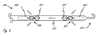
[0109]図5が、第1のモータ202に接続される近位側羽根車(ブレード201を備える)と、第2のモータ202’に接続される遠位側羽根車(ブレード20を備える)とを有する医療デバイスの例示の作用部分200を示す。流体ポンプに2つのモータを組み込むことにより、単一のモータの場合と等しい最大径を維持しながら利用可能なトルクを2倍にすることができる。これがデバイスのプロフィールを縮小するのを補助することができる。図5に示されるプッシュ-プルの形の実施形態では、近位側モータ202が作用部分(限定しないが、例えば、コイル状の強化ポリマーまたは網状の強化ポリマーなどの細長い強化ボディ213を一般に有する)を通して血液を引き込み、対して遠位側モータ202’が作用部分を通して血液を押し込む。左心室の補助のために使用される場合、大動脈弁が血液流入ポート207と血液流出ポート208との間に配置されることになる。細長いボディ213が、ボディ213の径方向外側部分上にある流入アパーチャ207と、ボディ213の径方向外側部分上にある流出アパーチャ208とを有する。矢印がアパーチャを通って流れる血液の方向を示しており、ここではページの右側が「遠位側」である。
[0108] The present disclosure further includes a working portion having a plurality of impellers.
[0109] FIG. 5 shows a proximal impeller (comprising blades 201) connected to a
[0110]図6A~6Cが作動部分30の例示の実施形態を示しており、ここでは、近位側モータ302が作用部分(例えば、コイル状の強化ポリマーまたは網状の強化ポリマーなどの強化ボディ313を有することができる)を通して血液を引き込み、対して遠位側モータ302’が拡大可能な側部ルーメン311を介して作用部分を通るように血液を押し込む。近位側モータ302が近位側羽根車301の回転を制御し、また近位側羽根車301の回転を引き起こし、遠位側モータ302が遠位側羽根車301’の回転を制御し、また遠位側羽根車301’の回転を引き起こす。作用部分内のアパーチャ307および308には参照符号が付される。拡大可能な側部ルーメン311は、限定しないが、例えば、拡大可能な概略網状の構造を配備すること、または遠位側羽根車301’により生じる圧力の増大により側部ルーメンを単純に膨張させること、などの機械的手法を利用して、拡大され得る。作用部分が、遠位側領域のところに入口アパーチャ307をさらに有する。側部ルーメン311が、カテーテルの外側部分において非円筒形のプロフィールを形成するようなかたちで、細長いボディ313の一方側を拡大するように構成され得るか、または代替の図6Cの断面図で示されるように、主要な補強カテーテルのより全体を取り囲むように拡大することもできる。ボディ313の中に流入する血液が近位側モータ302および羽根車301の中への流入を支援するのを可能にするためには、強化ボディの側部に沿うにスペースの少なくとも一部分は露出されたままであるべきである(例えば、入口ポート307のうちの1つの入口ポート)。左心室の補助のために使用される場合、大動脈弁が2つのセットの血液流入ポート307と血液流出ポート308との間に配置され得る。
[0110] FIGS. 6A-6C illustrate an exemplary embodiment of the working
[0111]図7A~7Eが、複数の羽根車を備える作用部分(400)の別の例示の実施形態を示している。このプル-プルの形の実施形態では、2つの羽根車の各々が、流れを示す矢印によって示されるように、作用部分のルーメンを通して血液を引き込み、側方流出式の出口ホースを通して血液を押し込む。アパーチャ407が流入アパーチャであり、流出アパーチャ408が流出アパーチャである。これらの羽根車が血液は運ぶための相対的な真空を引き込むことから、ルーメンは折り畳まれるのを防止するかまたは最小限に抑えるために補強されなければならない。図7B~7Eが図7Aに示される断面図をそれぞれ示しており、その断面の下に図7B~7Eが示される。図7A~7Eの実施形態は、その中でモータおよび羽根車が同軸に位置している主ルーメン413を示す。主ルーメン413はコイル状に強化されるかまたは網状に強化されていてよく、あるいは他の構造で強化されていてよい。図6A~6Cの副ルーメン311と同様に、拡大する、網状、ステント状、またはバスケット状のデザインなどにより、副ルーメン411が主ルーメン413から外側に拡大する。血液流入路が作用部分の遠位端の近くにある。出口孔408の上方にある三日月形状の外側ルーメン411を示す図7Cの断面図B-Bで見ることができるように、遠位側モータ402’および羽根車401’が、羽根車401’に隣接するかまたは羽根車401’の近くにある少なくとも側方孔408から血液を外に出すように運ぶ。遠位側モータ402および羽根車401が、近位側羽根車401に隣接するかまたは近位側羽根車401の近くにある側方孔408から血液を外に出すように運ぶ。
[0111] FIGS. 7A-7E illustrate another exemplary embodiment of a working portion (400) that includes multiple impellers. In this pull-pull embodiment, each of the two impellers draws blood through the lumen of the working part and forces it through the side-flow outlet hose, as indicated by the flow arrows.
[0112]図8A~8Fが複数の羽根車500および501’を有する作用部分(500)の別の例示の実施形態を示しており、矢印が流れ方向を示している。このプッシュ-プッシュの形の実施形態では、作用部分500が、プッシュ-プッシュの形の構成で配置される、二重のモータおよび羽根車を有し、ここでは、各羽根車が作用部分のルーメン(511または513)を通して血液を押し込み、側方流出式のアパーチャまたは近位端流出式のアパーチャ508を通して血液を押し込む。これらの羽根車が血液を運ぶための圧力を生じさせることから、ルーメン511および513は折り畳まれるのを防止するために必ずしも補強される必要はなく、外側ルーメン511が、ポンプによって増大する血圧により流体で膨張され得る。この実施形態は、その中でモータおよび羽根車が同軸に位置している主ルーメン513を示す。主ルーメン513が、例えば、コイル状に強化されるかまたは網状に強化されていてよく、あるいは他の構造で強化されていてよい。副ルーメン511が上記の副ルーメンのうちのいずれかの副ルーメンのように外側に拡大することができるか、またはポンプによって増大する血圧による流体での膨張により外側に拡大することができる。血液流入路が作用部分の遠位端の近くにある。ルーメン511および513の両方が、側方アパーチャ508、開いている網状構造、または同様の出口通路などを通して、作用部分の近位側部分から血液を外に出す。2つの羽根車501および501’が各端部から外に出るスピンドルを備える単一のモータによって駆動され得るか、または図8Fに示されるように、背中合わせとなる方向を向きかつ互いに隣接する2つのモータ502および502’が、血液の圧送を始動するために利用可能であるトルクを効果的に2倍にする。
[0112] Figures 8A-8F illustrate another exemplary embodiment of a working portion (500) having
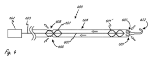
[0113]図9が、作用部分(600)が複数の羽根車を有するような、医療デバイスの例示の実施形態を示している。医療デバイスが、医療デバイスの細長い部分の近位端のところに配置されるリモートモータ602を有する。リモートモータ602が駆動ケーブル603に結合され、駆動ケーブル603が羽根車601および601’に結合される。モータ602が羽根車を駆動する。モータを離れたところに位置させることにより、所望される程度でより小さい挿入可能なカテーテルシャフトの中に嵌め込まれる場合よりも大きいモータが使用され得る。カテーテル内にモータを有する本明細書の実施形態のうちの任意の実施形態が、1つまたは複数のリモートモータを有するように修正され得る。作用部分600が、各々の羽根車のためのまたはいずれかの羽根車のためのカテーテル側方孔608、あるいは径方向ではなく軸方向において流れを最大にするのを可能にする端部アパーチャ607、などの、多様な流入のための構成および配置ならびに流出のための構成および配置を有することができる。羽根車の間を延在する細長いボディ604が、例えば、溶融ポリマー層の間に挟まれるワイヤーコイルにより、または概略網状構造により、構造的に補強され得る。コイル状の補強デザインは、一般に、網状の補強デザインよりも高い柔軟性を有し、高いレベルの柔軟性は、一般に、作用部分を定位置まで誘導することにおいて所望されるものである。この実施形態または本明細書の任意適切な他の実施形態が、カテーテルハンドルまたは結合されるハンドル/ハブの組み合わせを備えるリモートモータを有することもできる。
[0113] FIG. 9 depicts an exemplary embodiment of a medical device in which the working portion (600) has multiple impellers. The medical device has a
[0114]図10が、作用部分(1100)が複数の羽根車を有するような、医療デバイスの例示の実施形態を示している。作用部分1100が、モータ1102’に結合される遠位側羽根車1101’を有する。作用部分1100が近位側羽根車1101をさらに有し、近位側羽根車1101がリモートモータ1102に結合され、リモートモータ1102が駆動ケーブル1103を介して動作可能に接続される。遠位側モータ1102’が作用部分の遠位端の近くに位置し、羽根車1101’を駆動し、羽根車1101’が作用部分のルーメンを通して血液を押し込み、一方で近位側リモートモータ1102が、作用部分の近位端のより近くに配置されるケーブル駆動式の近位側羽根車1101を駆動する。使用時、本明細書の他の作用部分を用いる場合と同様に、作用部分1100が、概して2つの羽根車の間のロケーションのところでボディ1113が弁(例えば、大動脈弁)を横断することになるように、配置され得る。
[0114] FIG. 10 shows an example embodiment of a medical device in which the working portion (1100) has multiple impellers. Working
[0115]図11が、作用部分(1200)が複数の羽根車を有するような、医療デバイスの例示の実施形態を示している。作用部分1200が、近位側羽根車1201に結合される直接駆動式の近位側モータ1202を有する。外部モータ1202’が駆動ケーブル1203を介して遠位側羽根車1201’に動作可能に接続される。駆動ケーブル1203が近位側内部モータ1202に沿ってかつ隣接して延在するルーメン内に構成され得、したがって作用部分ルーメンの中まで延在し、ルーメン内で概してセンタリングされるように方向付けられ、その結果、遠位側羽根車1201’が作用部分のルーメン内でセンタリングされる。任意選択のセンタリング要素は図示されないが、これは、限定しないが、例えば、作用部分ルーメン内で羽根車1201’が安定してセンタリングされるようにするための、作用部分の外壁1213と回転駆動ケーブル1203を支持する回転軸受要素との間に取り付けられる2対のまたは3組のストラットなどである。使用され得る例示のセンタリングストラットとして、図2Aおよび2Bのストラット29がある。
[0115] FIG. 11 illustrates an exemplary embodiment of a medical device in which the working portion (1200) has multiple impellers. The working
[0116]図12が、作用部分(1300)が複数の羽根車を有するような、医療デバイスの例示の実施形態を示している。医療デバイスが、それぞれ駆動ケーブル1303および1303’に動作可能に接続されるリモートモータ1302および1302’を有する。駆動ケーブル1303および1303’がそれぞれ近位側羽根車1301および遠位側羽根車1301’に動作可能に接続され、近位側羽根車1301および遠位側羽根車1301’の両方が作用部分1300内に配置される。駆動ケーブル1303および1303’が近位側領域1310に隣り合うように配置され、駆動ケーブル1303’が一定の距離にわたって作用部分の周縁部に沿って延在し、したがってルーメンの中央に向かって延在する。図11を参照して説明したようなセンタリング要素も含まれ得る。駆動ケーブルは近位側領域1310内の別個のルーメン内にあってよい。駆動ケーブル1303’が外部ルーメン内にあってよいかまたは1つまたは複数の軸受要素の中にあってよく、駆動ケーブル1303’が作用部分の周縁部1316に沿って延在する。
[0116] FIG. 12 depicts an example embodiment of a medical device in which the working portion (1300) has multiple impellers. A medical device has
[0117]医療デバイス(1330)が複数の羽根車を有するような本明細書の実施形態のうちの任意の実施形態で、デバイスが羽根車を多様な速度で回転させるように適合され得る。図13Aが、内側駆動部材1338および外側駆動部材1336の両方に結合されるギアセット1340を有する医療デバイスを示しており、内側駆動部材1338および外側駆動部材1336がそれぞれ遠位側羽根車1334および近位側羽根車1332に動作可能に接続される。デバイスが、内側駆動部材1338の回転を始動するモータ1342をさらに有する。内側駆動部材1338が外側駆動部材1336を通って延在する。モータ1332が作動することにより、減速比(underdrive ratio)および加速比(overdrive ratio)を理由として2つの羽根車が多様な速度で回転するころになる。ギアセット1340が、近位側羽根車または遠位側羽根車のいずれかをもう一方より迅速に駆動するように適合され得る。本明細書のデバイスのうちの任意のデバイスが、羽根車を多様な速度で駆動するための本明細書のギアセットのうちの任意のギアセットを有することができる。
[0117] In any of the embodiments herein where the medical device (1330) has multiple impellers, the device may be adapted to rotate the impellers at various speeds. FIG. 13A shows a medical device having a
[0118]図13Bが、異なる羽根車を異なる速度で回転させるようにやはり適合される二重羽根車デバイス(1350)の代替的実施形態の一部分を示している。ギアセット1356が内側駆動部材1351および外側駆動部材1353の両方に結合され、内側駆動部材1351および外側駆動部材1353がそれぞれ遠位側羽根車1352および近位側羽根車1354に結合される。デバイスが図13Aのようなモータをさらに有する。図13Aおよび13Bは、ギアセットが近位側羽根車を遠位側羽根車より低速でまたは高速で駆動するように如何にして適合され得るかを示す。
[0118] FIG. 13B shows a portion of an alternative embodiment of a dual impeller device (1350) that is also adapted to rotate different impellers at different speeds. A
[0119]代替的実施形態では、共通の駆動ケーブルまたは駆動シャフトが2つの(または、それより多くの)羽根車の回転を始動することができるが、2つの羽根車のブレードピッチ(または、旋回方向の湾曲角度(angle of rotational curvature))は異なっていてよく、遠位側羽根車または近位側羽根車がもう一方の羽根車より急傾斜の角度または緩やかな角度を有する。これにより、ギアセットを有する場合と同様の効果を生み出すことができる。図13Cが、近位側羽根車1364および遠位側羽根車1362に結合されさらに図示されない結合される共通の駆動ケーブル1366を有する医療デバイス(1360)の一部分を示す。本明細書の近位側羽根車が、本明細書の遠位側羽根車より高いピッチまたは低いピッチを有することができる。複数の羽根車を備える本明細書の作用部分のうちの任意の作用部分が、異なるピッチを有する第1および第2の羽根車を有するように修正され得る。
[0119] In alternative embodiments, a common drive cable or drive shaft can initiate the rotation of two (or more) impellers, but The angle of rotational curvature may be different, with the distal or proximal impeller having a steeper or more gradual angle than the other impeller. This can produce the same effect as when a gear set is used. FIG. 13C shows a portion of a medical device (1360) having a
[0120]図14が、第1および第2の羽根車を異なる速度で回転させることができる流体ポンプ1370の例示の代替的実施形態を示す。第1のモータ1382が遠位側羽根車1372に結合されるケーブル1376を駆動し、対して第2のモータ1384が近位側羽根車1374に結合される外側駆動部材1378を駆動する(ギアセット1380を介する)。駆動ケーブル1376が外側駆動部材1378を通って延在する。モータが個別に制御され得、動作させられ得、したがって2つ羽根車の速度が別個に制御され得る。このシステムのセットアップが、複数の羽根車を有する本明細書の任意のシステムと共に使用され得る。
[0120] FIG. 14 illustrates an example alternative embodiment of a
[0121]使用時、本明細書の作用部分が弁(例えば、大動脈弁)などのダメージを受けやすい構造に跨るように配置され得る。弁に対してダメージを与えるのを回避することが有用である可能性があり、作用部分がこれを行うように適合および構築され得る。大動脈(または、例えば他の同様の弁)が中心部の近くで3つの弁が接触するかたちで一般には閉じることから、作用部分が弁を横断するかまたはその弁に跨って延びているところのロケーションで、本明細書の作用部分のうちの任意の作用部分の外側部分が非円形構成を有することが有利である可能性がある。大動脈に理想的に適合するためには、非円形のカテーテルボディを回転可能に位置合わせすることは望ましくない可能性がある。図15A、15B、および15Cが、本明細書の任意の作用部分に組み込まれ得るような、本明細書の作用部分のための例示の外側プロフィール構成を示す。図15Dが、比較のために円形の外側プロフィール構成を示す。 [0121] In use, the active portion herein may be positioned to straddle a susceptible structure, such as a valve (eg, an aortic valve). It may be useful to avoid causing damage to the valve, and the working part may be adapted and constructed to do this. Since the aorta (or, for example, other similar valves) generally closes with three valves touching near the center, it is important to note that where the active portion extends across or astride the valve, In some locations, it may be advantageous for the outer portion of any of the working parts herein to have a non-circular configuration. To ideally fit the aorta, rotatably positioning a non-circular catheter body may not be desirable. 15A, 15B, and 15C illustrate example outer profile configurations for the working portions herein, as may be incorporated into any working portion herein. FIG. 15D shows a circular outer profile configuration for comparison.
[0122]いくつかの実施形態では、作用部分が、弁を横断するところの領域内に適合性のまたは半適合性の外部構造を有することができ、その結果、作用部分を押圧する弁の力が外部構造を少なくとも部分的に変形させることになり、それにより、外部構造により弁に加えられる反力(reactionary force)を少なくとも部分的に低減する。これにより、作用部分が弁を横断するところのロケーションにおいて弁に対してダメージを与えるのを防止するのを補助することができる。 [0122] In some embodiments, the working portion can have a conformable or semi-conformable external structure in the area where it traverses the valve, such that the force of the valve pushing against the working portion will at least partially deform the outer structure, thereby at least partially reducing the reactive force exerted on the valve by the outer structure. This can help prevent damage to the valve at locations where the active part crosses the valve.
[0123]また、弁小葉などの脆弱な構造のいかなる摩擦もその構造に対して最小限にしかダメージを与えないようにするために、作用部分のうちの任意の作用部分の外側部分を滑らかにすることが有利である可能性がある。弁のこの領域のところにステント状の構造または同様の構造があると、弁に対してダメージを与える可能性があるような突出スポット(尖っていないチーズおろし器のような)を生じさせる可能性がある。このような突起部の高さを最小にすることおよび/またはこれらの突起部の間の距離を最小にすることが有益である可能性があり、ダメージを受けやすい解剖学的構造にダメージを与えるのを防止することができる可能性がある。 [0123] Also, the outer portion of any of the working parts should be smoothed to ensure that any friction of a fragile structure such as a valve leaflet will only cause minimal damage to that structure. It may be advantageous to do so. Stent-like structures or similar structures in this area of the valve can create protruding spots (like a blunt cheese grater) that can cause damage to the valve. There is. It may be beneficial to minimize the height of such protrusions and/or minimize the distance between these protrusions and avoid damage to susceptible anatomical structures. It may be possible to prevent this.
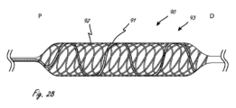
[0124]図16は作用部分1600を有する例示の血管内流体ポンプの遠位側部分を示す側面図であり、ここでは、作用部分1600が近位側羽根車1606および遠位側羽根車1616を有し、近位側羽根車1606および遠位側羽根車1616の両方が駆動ケーブル1612に動作可能に接続される。図16では作用部分1600が拡大構成であるが、低プロフィールで送達され得るようにするために、送達構成となるように折り畳まれるように適合される。羽根車が駆動ケーブル1612に取り付けられ得る。駆動ケーブル1612が図示されない外部モータに動作可能に接続され、細長いシャフト1610を通って延在する。
[0124] FIG. 16 is a side view of a distal portion of an exemplary intravascular fluid pump having a working
[0125]作用部分1600が、近位側羽根車1606の近位端より近位側に延在する近位端1620と、遠位側羽根車1616の遠位端より遠位側に延在する遠位端1608とをこの実施形態では有する拡大可能部材1602をさらに有する。拡大可能部材1602が、羽根車の軸方向長さに沿って、羽根車の径方向外側に配置される。拡大可能部材1602が、折り畳み可能および拡大可能となるように、医療技術分野で知られている多くの種類の拡大可能構造と同様の手法で構築され得、またそれらと同様の材料から作られ得る。これらの手法または方法の実施例が本明細書で提供される。
[0125] The working
[0126]作用部分1600が拡大可能部材1602に結合される導管1604をさらに有し、拡大可能部材1602が長さLを有し、羽根車の間を軸方向に延在する。導管1604が2つの羽根車の間に流体ルーメンを形成して提供する。使用時、流体が、導管1604によって提供されるルーメンを通って移動する。本明細書の導管は不透過性であるか、あるいはルーメンを画定することができる限りにおいては、半透過性であってもよいかまたはさらには多孔性であってもよい。また、特に明記しない限り、本明細書の導管は可撓性である。本明細書の導管が、作用部分の少なくとも一部分の周りを完全に(つまり、360度で)延在する。作用部分1600内で、導管が拡大可能部材1602の周りを完全に延在するが、拡大可能部材1602の近位端1602または遠位端1608までは延在しない。拡大可能部材の構造が、流入「I」を可能にするための少なくとも1つの入口アパーチャと、流出「O」を可能にするための少なくとも1つの流出アパーチャとを作る。導管1604が、導管を有さない場合に作用部分1600が有することになる動力学と比較して、羽根車の圧送の動力学を改善する。
[0126] Working
[0127]拡大可能部材1602が多様な構成を有することができ、医療技術分野の任意の種類の拡大可能ステントまたはステント状デバイスなどの、あるいは本明細書で提供される任意の他の実施例などの、多種多様な材料から作られてよい。限定しないが、例えば、拡大可能部材1602が、24個の端部を有する網(24-end braid)などの開いた網状の構成を有してもよい。しかし、より多くのまたは少ない編み込みのワイヤーが使用されてもよい。拡大可能部材のための例示の材料はニチノールであるが、他の材料が使用されもよい。拡大可能部材1602が示されるような拡大構成を有し、ここでは、羽根車の間を軸方向に延在する拡大可能部材の中央領域1622の最外寸法と比較して、少なくとも、拡大可能部材が羽根車の径方向外側に配置されるところの領域の拡大可能部材の最外寸法(作用部分の長手方向軸を基準として直角に測定される)の方が大きい。駆動ケーブル1612がこの実施形態では長手方向軸と同軸である。使用時、中央領域が大動脈弁などの弁を跨るように配置され得る。いくつかの実施形態では、拡大可能部材1602が、拡大可能部材内で羽根車が軸方向に存在するところでは12~24F(4.0~8.0mm)の最外寸法まで拡大するように、かつ羽根車の間の中央領域1622内で10~20F(3.3~6.7mm)の最外寸法まで拡大するように、適合されて構築される。中央領域の外側寸法が小さいことで、弁に作用する力を低減することができ、それにより弁に対するダメージを低減するかまたは最小にすることができる。羽根車の領域での拡大可能部材の寸法が大きいことで、使用時に作用部分を軸方向において安定させるのを補助することができる。拡大可能部材1602が概略ダンベル構成を有する。拡大可能部材1602が、羽根車領域から中央領域1622へと移行するところでテーパ状となりさらには拡大可能部材1602の遠位端および近位端のところでもやはりテーパ状となる外側構成を有する。
[0127] The
[0128]拡大可能部材1602がシャフト1610に結合される近位端1620と、遠位側先端部1624に結合される遠位端1608とを有する。羽根車および駆動ケーブル1612が、拡大可能部材と導管との組立体の中で回転する。駆動ケーブル1612が遠位側先端部1624を基準として軸方向において安定させられるが、遠位側先端部1624を基準として自由に回転することができる。
[0128]
[0129]いくつかの実施形態では、拡大可能部材1602が、拡大可能部材にかかる端から端までの引張張力(pulling tension)によって折り畳まれ得る。これには、折り畳まれた状態での外側寸法を有するような折り畳み構成となるまで拡大可能部材1602を軸方向に伸ばすような線形の動きが含まれてよい(限定しないが、例えば、5~20mmだけ移動するなど)。また、拡大可能部材1602は、拡大可能部材/導管の組立体の上でシースなどの外側シャフトを押し込んでそれにより折り畳み状態の送達構成となるように拡大可能部材および導管を折り畳むことによっても、折り畳まれ得る。
[0129] In some embodiments, the
[0130]羽根車1606および1616はまた、縮小した最外寸法(作用部分の長手方向軸に対して直角に測定される)となるように1つまたは複数のブレードを伸ばすかまたは径方向に圧縮させるように、適合されて構築される。限定しないが、例えば、本明細書の羽根車のうちの任意の羽根車が、米国特許第7,393,181号で説明される羽根車のうちの任意の羽根車などのように、ばね特性を有するプラスチック配合物から作られる1つまたは複数のブレードを有することができる。米国特許第7,393,181号の開示が参照により本明細書に組み込まれ、また本開示により別の意味で示されない限りにおいて本明細書の実施形態に組み込まれ得る。別法として、例えば、1つまたは複数の折り畳み可能な羽根車が、その開示が参照により本明細書に組み込まれる米国特許第6,533,716号で説明されるようなワイヤーフレームなどの、ワイヤーフレームに交差するウェビングとして機能するポリマーまたは他の材料を有する超弾性ワイヤーフレームを備えることができる。
[0130] The
[0131]作用部分1600の流入構成および/または流出構成は大部分が本質的に軸方向であってよい。
[0132]医療デバイスを折り畳んだり拡大したりするための、例示の、被覆物の中に収容する(sheathing)および被覆物から出す(unsheathing)手法および概念は、例えば、その開示が参照により本明細書に組み込まれる米国特許第7,841,976号または米国特許第8,052,749号で説明されて示される手法および概念などから、知られている。
[0131] The inflow and/or outflow configuration of working
[0132] Exemplary sheathing and unsheathing techniques and concepts for collapsing and expanding medical devices are described, e.g., herein by reference. No. 7,841,976 or US Pat. No. 8,052,749, incorporated herein by reference.
[0133]図17は、流体移動システムの例示の実施形態の遠位側部分の配備構成(体外)を示す側面図である。例示のシステム1100が、作用部分1104と、作用部分1104から延在する細長い部分1106とを有する。細長い部分1106が、簡潔さのための図示されないシステムのさらに近位側の領域まで延在してよく、このさらに近位側の領域が例えばモータを有することができる。作用部分1104が、作用部分1104の長手方向軸LAに沿って軸方向において離隔される、第1の拡大可能部材1108および第2の拡大可能部材1110を有する。本文脈の軸方向において離隔されるとは、第1の拡大可能部材の全体が、作用部分1104の長手方向軸LAに沿って、第2の拡大可能部材の全体から軸方向において離隔される、ことを意味する。第1の拡大可能部材1108の第1の端部1122が第2の拡大可能部材1110の第1の端部1124から軸方向において離隔される。
[0133] FIG. 17 is a side view illustrating a deployed configuration (extracorporeal) of a distal portion of an exemplary embodiment of a fluid transfer system. The
[0134]第1の拡大可能部材1108および第2の拡大可能部材1110の各々が、概して、複数のアパーチャ1130を画定するように互いを基準として配置される複数の細長いセグメントを有する。第2の拡大可能部材1110内の、複数のアパーチャ1130のうちの1つのアパーチャのみに参照符号が付される。拡大可能部材が多種多様な構成を有することができ、多種多様な手法で構築され得、これは、限定しないが、例えば、米国特許第7,841,976号の構成または構築のうちの任意の構成または構築などであるか、または自己拡大する金属の内部人工装具材料として説明される、米国特許第6,533,716号のチューブなどである。限定しないが、例えば、拡大可能部材の一方または両方が網状構成を有することができるか、または管状要素をレーザ切断することにより少なくとも部分的に形成され得る。
[0134] Each of first
[0135]作用部分1104が、第1の拡大可能部材1108および第2の拡大可能部材1110に結合されて配備構成において軸方向において第1の拡大可能部材1108と第2の拡大可能部材との間を延在する導管1112をさらに有する。導管1112の中央領域1113が一定の軸方向距離1132に跨るように延びており、ここでは作用部分が第1の拡大可能部材1108および第2の拡大可能部材1110を有さない。中央領域1113は軸方向において拡大可能部材の間にあるとみなされてよい。導管1112の遠位端1126は第2の拡大可能部材1110の遠位端1125の程度までは遠位側に延在せず、導管の近位端1128は第1の拡大可能部材1108の近位端1121の程度までは近位側に延在しない。
[0135] An
[0136]本明細書の開示が拡大可能部材に結合される導管に言及する場合、本文脈での結合されるという用語は、導管が拡大可能部材に直接に取り付けられてその結果として導管が拡大可能部材に物理的に接触する、ということを必要としない。しかし、直接に取り付けられない場合でも、本文脈での結合されるという用語は、拡大可能部材が拡大するかまたは折り畳まれるときに導管も異なる構成および/またはサイズへと移行し始めることになるように、導管および拡大可能部材が一体に接合される、ことを意味する。したがって、本文脈での結合されるとは、導管を結合している拡大可能部材が拡大構成と折り畳み構成との間で移行する場合に導管が移動することになる、ことを意味する。 [0136] When the disclosure herein refers to a conduit that is coupled to an expandable member, the term coupled in this context means that the conduit is attached directly to the expandable member so that the conduit is expanded. It does not require physical contact with the enabling member. However, even if not directly attached, the term coupled in this context means that when the expandable member expands or collapses, the conduit also begins to transition to a different configuration and/or size. means that the conduit and the expandable member are joined together. Thus, coupled in this context means that the conduit will move when the expandable member joining the conduit transitions between an expanded configuration and a collapsed configuration.
[0137]本明細書の導管のうちの任意の導管がある程度まで変形可能であってよい。例えば、導管1112が、図17に示される構成の方へと作用部分1104が配備されるときの、例えば使用時の弁組織(例えば、小葉)または代替の弁からの力に反応して、導管の中央領域1113を径方向内側(LAに向かう方向)へとある程度で変形させるのを可能にする1つまたは複数の材料で作られてよい細長い部材1120を有する。いくつかの実施形態では、導管が拡大可能部材の間で強固に伸ばされ得る。別法として、導管は、適合性を向上させるような緩みを有するように設計されてもよい。これは、大動脈弁などの脆弱な構造に跨って作用部分が配置される場合に所望される可能性があり、それにより弁内の点応力(point stress)を最小にするようなかたちで弁が導管を圧縮するのを可能にすることができる。いくつかの実施形態では、導管が、近位側拡大可能部材および遠位側拡大可能部材に取り付けられる膜を有することができる。本明細書の任意の導管のために使用され得る例示の材料には、限定しないが、ポリウレタンゴム、シリコーンゴム、アクリルゴム、延伸ポリテトラフルオロエチレン、ポリエチレン、ポリエチレンテレフタレートが含まれ、これには、その任意の組み合わせも含まれる。
[0137] Any of the conduits herein may be deformable to some extent. For example, when the
[0138]本明細書の導管のうちの任意の導管が、例えば、25.4μm(1thou)から381μm(15thou)まで、38.1μm(1.5thou)から381μm(15thou)まで、38.1μm(1.5thou)から254μm(10thou)まで、または50.8μm(2thou)から254μm(10thou)まで、といったように、127~508μm(5~20thousandths of an inch(thou))の厚さを有することができる。 [0138] Any of the conduits herein may be, for example, from 1thou to 15thou, from 15thou to 15t; The thickness may be from 5 to 20 thousandths of an inch (thou), such as from 1.5 to 10 thousand, or from 2 to 10 thousand, and so on. can.
[0139]本明細書の導管のうちの任意の導管、または導管の少なくとも一部分が、血液に対して不透過性であってよい。図17では、作用部分1104が、導管1112の遠位端1126から導管1112の近位端1128まで延在するルーメンを有する。このルーメンは中央領域1113内では導管1112によって画定されるが、軸方向において中央領域1113に隣接する領域では、導管と、拡大可能部材の一部分と、の両方によって画定されるとみなされてよい。しかし、この実施形態では、ルーメンを存在させるものは導管の材料であり、この導管の材料が血液が導管を通過するのも防止する。
[0139] Any of the conduits herein, or at least a portion of the conduit, may be impermeable to blood. In FIG. 17, working
[0140]1つまたは複数の拡大可能部材に固着される本明細書の導管のうちの任意の導管は、別の意味で示されない限りにおいて、1つまたは複数の拡大可能部材の径方向外側にまたは1つまたは複数の拡大可能部材の径方向内側にあるいはその両方に導管が配置されることになるように、固着され得、拡大可能部材が導管材料で充填されてよい。 [0140] Any conduit herein that is secured to one or more expandable members is radially outwardly of the one or more expandable members, unless otherwise indicated. Alternatively, the expandable members may be filled with conduit material such that the conduit is disposed radially inwardly of one or more of the expandable members or both.
[0141]近位側拡大可能部材および遠位側拡大可能部材が、ルーメンを作るために導管を開いた構成で維持するのを補助し、一方で後で説明するように各々が羽根車のための作動環境も作る。配備構成時、拡大可能部材の各々が、それぞれの羽根車を基準として離隔される関係で維持され、それにより羽根車が拡大可能部材に接触することなく拡大可能部材内で回転するのを可能にする。作用部分1104が第1の羽根車1116および第2の羽根車1118を有し、第1の羽根車1116が第1の拡大可能部材1108内で径方向に配置され、第2の羽根車1118が第2の拡大可能部材1110内で径方向に配置される。この実施形態では、2つの羽根車が、別個の分離される羽根車ではあるが、共通の駆動機能(例えば、駆動ケーブル1117)に動作可能に接続され、その結果、駆動機能が作動されるときに2つの羽根車が一体に回転するようになる。この配備構成では、軸方向において拡大可能部材1108および1110が離隔されるのとちょうど同じように、羽根車1116および1118が長手方向軸LAに沿って軸方向において離隔される。
[0141] A proximal expandable member and a distal expandable member assist in maintaining the conduit in an open configuration to create a lumen, while each for an impeller as described below. It also creates an operating environment. In the deployed configuration, each of the expandable members is maintained in a spaced relationship relative to a respective impeller, thereby allowing the impellers to rotate within the expandable member without contacting the expandable member. do. The working
[0142]羽根車1116および1118は、それぞれ、拡大可能部材1108および1110の端部の中で軸方向にも存在する(拡大可能部材1108および1110内で径方向に存在することに加えて)。本明細書の羽根車は、拡大可能部材が拡大可能部材の中央領域から作用部分の長手方向軸に向かって延在するストラット(例えば、側面図においてテーパ状であるストラット)を有する場合であっても、拡大可能部材内で軸方向に存在するとみなされてよい。図17では、第2の拡大可能部材1110が第1の端部1124(近位端)から第2の端部1125(遠位端)まで延在する。
[0142] Impellers 1116 and 1118 are also present axially within the ends of
[0143]図17では、羽根車1118の遠位側部分が導管1112の遠位端1126を越えて遠位側に延在し、羽根車1116の近位側部分が導管1112の近位側部分1128を越えて近位側に延在する。この図では、この配備構成において、各羽根車の一部分がこの導管内で軸方向に存在する。
[0143] In FIG. 17, a distal portion of
[0144]図17に示される例示の実施形態では、羽根車1116および1118が共通の駆動機能1117に動作可能に接続され、この実施形態では、羽根車の各々が駆動機構1117に結合され、駆動機構1117がシャフト1119および作用部分1104を通って延在する。駆動機能1117が、例えば、回転時に羽根車も回転させるような細長い駆動ケーブルであってよい。この実施例では、示されるように、駆動機構1117が遠位側先端部1114まで延在して軸方向において遠位側先端部1114を基準として固定されるが、駆動機構1117は作動時に遠位側先端部1114を基準として回転するようにも適合される。したがって、この実施形態では、駆動機構1117の回転時に、羽根車および駆動機構1117が一体に回転する。駆動機能を回転させるのに、モータ(外部モータ)を用いる機構などの、任意の数の知られている機構が使用されてよい。
[0144] In the exemplary embodiment shown in FIG. 17,
[0145]拡大可能部材および導管は、回転動作を可能とするようには羽根車および駆動機構に接続されない。この実施形態では、近位側拡大可能部材1108の近位端1121がシャフト1119に結合され、シャフト1119が細長い部分1106のシャフト(例えば、外側カテーテルシャフト)であってよい。近位側拡大可能部材1108の遠位端1122が中央管状部材1133に結合され、駆動機構1117が中央管状部材1133を通って延在する。中央管状部材1133が導管1112内の近位側拡大可能部材1108から遠位側に延在し、さらには遠位側拡大可能部材1110の近位端1124に結合される。したがって、駆動機構1117が中央管状部材1133の中で中央管状部材1133を基準として回転する。中央管状部材1133が近位側拡大可能部材1108から遠位側拡大可能部材1110まで軸方向に延在する。遠位側拡大可能部材1110の遠位端1125が示されるように遠位端1114に結合される。駆動機構1117は先端部1114を基準として回転するように適合されるが、軸方向において先端部1114に対して固定される。
[0145] The expandable member and conduit are not connected to the impeller and drive mechanism to enable rotational movement. In this embodiment,
[0146]作用部分1104が、折り畳まれてその配備構成(図17に示される)よりも小さいプロフィールとなるように適合および構成される。これにより、作用部分1104が折り畳み可能ではない場合において必要となるよりも低プロフィールの送達デバイス(より小さいFrenchサイズ)を使用して作用部分1104を送達することが可能となる。本明細書で具体的に記述されない場合であっても、任意の拡大可能部材および羽根車がより小さい送達構成となるようにある程度まで折り畳み可能となるように適合および構成され得る。
[0146] Working
[0147]本明細書の作用部分は、作用部分を基準として移動可能である外側シースを用いる手法などの、従来の手法を使用して折り畳み状態の送達構成となるように折り畳まれ得る(例えば、シースおよび作用部分の一方または両方を軸方向に移動させることによる)。限定しないが、例えば、以下の参考文献で示される任意のシステム、デバイス、または方法が、本明細書の作用部分を折り畳むのを促進するのに使用され得る:その開示が参照により本明細書に組み込まれる米国特許第7841,976号または米国特許第8,052,749号。 [0147] The working portions herein may be folded into a collapsed delivery configuration using conventional techniques, such as with an outer sheath that is movable relative to the working portion (e.g., by axially moving one or both of the sheath and the working part). For example, without limitation, any of the systems, devices, or methods set forth in the following references may be used to facilitate folding of the working portions herein: Incorporated U.S. Patent No. 7841,976 or U.S. Patent No. 8,052,749.
[0148]図18A~18Eが、図17に示される作用部分にいくつかの点で類似する例示の作用部分を示している。作用部分340は、作用部分が拡大されるときに軸方向において互いから離隔される2つの拡大可能部材と、2つの拡大可能部材の間を延在する導管とを有するという点が作用部分1104に類似する。図18Aが斜視図であり、図18Bが側断面図であり、図18Cおよび18Dが図18Bの図の断面の拡大側断面図である。
[0148] FIGS. 18A-18E illustrate an exemplary working portion that is similar in some respects to the working portion shown in FIG. 17. Working
[0149]作用部分340が近位側羽根車341および遠位側羽根車342を有し、近位側羽根車341および遠位側羽根車342が駆動ケーブルに結合されかつ動作可能に接続され、駆動ケーブルがその中にルーメンを画定する。ルーメンが、作用部分を所望のロケーションまで送達するのに使用され得るガイドワイヤーを収容するようにサイズ決定され得る。駆動ケーブルが、この実施形態では、第1のセクション362(例えば、巻かれた状態の材料)と、近位側羽根車341を結合させるところの第2のセクション348(例えば、管状部材)と、第3のセクション360(例えば、巻かれた状態の材料)と、遠位側羽根車342を結合させるところの第4のセクション365(例えば、管状材料)とを有する。これらの駆動ケーブルのセクションのすべてが等しい内径を有し、その結果ルーメンが一定の内径を有することになる。これらの駆動ケーブルのセクションが知られている取り付け手法を使用して互いに固着され得る。第4のセクション365の遠位端が作用部分の遠位側領域まで延在し、それにより、作用部分を位置決めするために作用部分を例えばガイドワイヤー上で前進させるのを可能にする。この実施形態では、第2のセクションおよび第4のセクションが第1のセクションおよび第3のセクションより高い剛性を有してよい。例えば、第2のセクションおよび第4のセクションが管状であってよく、第1のセクションおよび第3のセクションが剛性を低減するために巻かれた状態の材料であってよい。
[0149] The working
[0150]作用部分340が、近位側拡大可能部材343と、遠位側拡大可能部材344とを有し、近位側拡大可能部材343および遠位側拡大可能部材344の各々が羽根車のうちの1つの羽根車の径方向外側を延在する。拡大可能部材が、図18b~18Dで見ることができるように、羽根車の遠位端および近位端を越えて軸方向に延在してもよい遠位端および近位端を有する。2つの拡大可能部材に対して導管356が結合され、導管356が近位端353および遠位端352を有する。2つの拡大可能部材の各々が、複数の近位側ストラットおよび複数の遠位側ストラットを有する。近位側拡大可能部材343の中の近位側ストラットがシャフトセクション345まで延在してシャフトセクション345に固着され、シャフトセクション345が軸受361に結合され、駆動ケーブルが軸受361を通って延在し、回転するように構成およびサイズ決定される。近位側拡大可能部材343の遠位側ストラットが中央管状部材346の近位側領域(この事例では、近位端)まで延在してこの近位側領域に固着され、中央管状部材346が軸方向において拡大可能部材の間に配置される。中央管状部材346の近位端が図18Cに示されるように軸受349に結合され、駆動ケーブルが軸受349を通って延在し、回転する。遠位側拡大可能部材344の近位側ストラットが中央管状部材346の遠位側領域(この事例では、遠位端)まで延在してこの遠位側領域に固着される。さらに、軸受350が図18Dに示されるように中央管状部材346の遠位側領域に結合される。駆動ケーブルが軸受350を通って延在し、軸受350を基準として回転する。遠位側拡大可能部材の遠位側ストラットがシャフトセクション347(図18Aを参照)まで延在してシャフトセクション347に固着され、シャフトセクション347が遠位端の一部分とみなされてよい。シャフトセクション347が軸受351(図18Dを参照)に結合され、駆動ケーブルが軸受351を通って延在し、軸受351を基準として回転する。遠位側先端部が、スラスト軸受であってよい軸受366(図18Dを参照)をさらに有する。本記述に明確に含まれていない場合であっても、作用部分340はいくつかの点において作用部分1104に類似してよいか等しくてよい。この実施形態では、導管356が、作用部分1104の場合とは異なり、少なくとも羽根車の端部と同じ程度のところまで延在する。いずれの実施形態も、他の実施形態に記載される位置まで導管を延在させるように、修正され得る。いくつかの実施形態では、セクション360が、巻かれた状態の代わりに、管状セクションであってもよい。
[0150] The working
[0151]本明細書で特定の例示のロケーションが示され得るが、流体ポンプは身体内の多種多様なロケーションで使用可能となり得る。配置のためのいくつかの例示のロケーションには、弁に跨るように延びていることおよび弁の一方側または両側に配置されることといったような、大動脈弁または肺動脈弁の近傍が含まれ、また大動脈弁の事例では任意選択で、上行大動脈内に位置する一部分が含まれる。いくつかの他の実施形態では、例えば、ポンプが使用時にさらに下流に配置されてもよく、下行大動脈などの中に配置されてもよい。 [0151] Although specific example locations may be shown herein, fluid pumps may be operable at a wide variety of locations within the body. Some example locations for placement include near the aortic or pulmonary valve, such as extending across the valve and being placed on one or both sides of the valve; In the case of an aortic valve, a portion located within the ascending aorta is optionally included. In some other embodiments, for example, the pump may be placed further downstream in use, such as in the descending aorta.
[0152]図19が、図17のシステム100からの作用部分1104の例示の配置を示している。図19に示される1つの相違点は、導管が図18A~18Dの場合のように少なくとも羽根車の端部と同じ程度のところまで延在することである。図19が、大動脈弁を跨るように定位置に配置される配備構成の作用部分1104を示している。作用部分1104が、示されるように、限定しないが、例えば、大腿動脈アクセス(知られているアクセス手技)を介して、送達され得る。簡潔さのために示されないが、システム100が外側シースまたは外側シャフトをさらに有することができ、大動脈弁の近くのロケーションまでの送達中に作用部分1104が外側シースまたは外側シャフトの中に配置される。シースまたはシャフトが近位側に移動させられ得(上行大動脈「AA」の方に向かい、左心室「LV」から離れる)、それにより作用部分1104を配備して拡大するのを可能にする。例えば、シースが第2の拡大可能部材1110を拡大するのを可能にするために後退させられ得、継続して近位側に移動することにより第1の拡大可能部材1108を拡大させるのを可能にする。
[0152] FIG. 19 shows an example arrangement of the working
[0153]この実施形態では、第2の拡大可能部材1110が拡大して配備構成として配置されており、その結果、遠位端1125が左心室「LV」の中にあり、大動脈弁小葉「LV」の遠位側にあり、さらには環状部分の遠位側にある。さらに、近位端1124が小葉「VL」の遠位側に配置されている。しかし、いくつかの実施形態では、近位端1124が小葉VL内で軸方向にわずかに延在してもよい。この実施形態は、その長さに沿って測定する(長手方向軸に沿って測定する)場合に第2の拡大可能部材1110の少なくとも半分を左心室の中の存在させるような方法の実施例である。さらに、示されるように、これは、第2の拡大可能部材1110の全体が左心室の中に存在するような方法の実施例でもある。また、これは、第2の羽根車1118の少なくとも半分が左心室の中に配置されるような方法の実施例でもあり、さらには第2の羽根車1118の全体が左心室の中に配置されるような実施形態でもある。
[0153] In this embodiment, the second
[0154]外側シャフトまたは外側シースを継続して引っ込めることにより(および/または、外側シースまたは外側シャフトを基準として作用端部1104を遠位側に移動させることにより)、中央領域113が解放されて配備されるようになるまで、導管1112を解放することが継続される。拡大可能部材1108および1110が拡大することで、導管1112が図19に示されるようにより開いた構成となる。したがって、この実施形態では導管1112が拡大可能部材と等しい自己拡大特性を有さないが、作用端部の配備時に導管がより開いた配備構成をとるようになる。導管1112の中央領域1113の少なくとも一部分が大動脈弁との接合領域のところに配置される。図18では、小葉VLを越えて遠位側に延在する短い長さの中央領域1113が存在するが、中央領域1113の少なくとも一部分が軸方向において小葉の中に存在する。
[0154] By continuing to retract the outer shaft or outer sheath (and/or by moving the working
[0155]外側シャフトまたは外側シースを継続して引っ込めることにより(および/または、外側シースまたは外側シャフトを基準として作用端部1104を遠位側に移動させることにより)、第1の拡大可能部材1108が配備される。この実施形態では、第1の拡大可能部材1108が拡大されて配備構成として配置され(示されるように)、その結果、近位端1121が上行大動脈AA内に存在することになり、小葉「LV」の近位側にくることになる。さらに、遠位端1122が小葉VLの近位側に配置されているが、いくつかの方法では、遠位端1122が小葉VL内で軸方向にわずかに延在してもよい。この実施形態は、その長さに沿って測定する(長手方向軸に沿って測定する)場合に第1の拡大可能部材1110の少なくとも半分を上行大動脈内に存在させるような方法の実施例である。さらに、示されるように、これは、第1の拡大可能部材1110の全体がAAの中に存在するような方法の実施例でもある。また、これは、第1の羽根車1116の少なくとも半分がAAの中に配置されるような方法の実施例でもあり、さらには第1の羽根車1116の全体がAAの中に配置されるような実施形態でもある。
[0155] By continuing to retract the outer shaft or outer sheath (and/or by moving the working
[0156]作用部分1104を配備する間のまたは作用部分1104を配備した後の任意の時間で、作用部分のこの位置が、X線透視検査下などの任意の手法でアクセスされ得る。作用部分の位置は配備中または配備後の任意の時間で調整され得る。例えば、第2の拡大可能部材1110が解放された後であるが第1の拡大可能部材1108が解放される前において、作用部分1104が軸方向に移動させられ得(遠位側に、または近位側に)、それにより作用部分を再配置する。加えて、例えば、作用部分の全体がシースから解放されて所望の最終位置に達した後で、作用部分が再配置され得る。
[0156] At any time during or after deployment of the working
[0157]最初の配備の後で再配置が行われる場合であっても、図19に示される構成要素の位置(解剖学的構造を基準とする)が作用部分1104の多様な構成要素のための例示の最終位置としてみなされることを理解されたい。 [0157] Even if repositioning occurs after the initial deployment, the location of the components (relative to the anatomy) shown in FIG. It is to be understood that this is considered as the final position of the example.
[0158]本明細書の1つまたは複数の拡大可能部材が、自己拡大すること、機械的作動を介すること(例えば、拡大可能部材にかかる1つまたは複数の軸方向の力を介すること、拡大可能部材内で径方向に配置されて膨張して拡大可能部材を径方向外側に押し込む別個のバルーンを用いて、拡大されること、など)、またはその組み合わせなどの、多様な手法で、拡大されるように構成され得、そのようなかたちで拡大され得る。 [0158] One or more expandable members herein may be capable of self-expanding, via mechanical actuation (e.g., via one or more axial forces applied to the expandable member, expanding The expandable member may be expanded in a variety of ways, such as with a separate balloon disposed radially within the expandable member and inflated to force the expandable member radially outward, or a combination thereof. It can be configured and expanded as such.
[0159]本明細書で使用される拡大とは、一般に、1つまたは複数の構成要素が拡大されるときの具体的な手法に関係なく、より大きい径方向の最外寸法(長手方向軸を基準とする)を有するより大きいプロフィールへの再構成を意味するものである。例えば、自己拡大するおよび/または径方向外向きの力を受けるステントが、本明細書でこの用語が使用される場合と同じ意味として、「拡大」することができる。展開するかまたは広がるデバイスがより大きいプロフィールをとることができ、本明細書でこの用語が使用される場合と同じ意味として、拡大するとみなされ得る。 [0159] Enlargement, as used herein, generally refers to a greater radial outermost dimension (a longitudinal axis (reference) to a larger profile. For example, a stent that is self-expanding and/or subjected to radially outward forces can be "expanded" in the same sense as that term is used herein. A device that unfolds or spreads out can take on a larger profile and may be considered to expand in the same sense as that term is used herein.
[0160]羽根車が、同様に、その構成に応じた多様な手法で拡大されるように適合されて構成され得、そのようなかたちで拡大され得る。例えば、1つまたは複数の羽根車が、シースから解放されるとき、この羽根車のデザインの材料および/または構成を理由として、別のより大きいプロフィールの構成まで、またはそのような構成の方へ、自動で戻る(例えば、その両方が参照により本明細書に組み込まれる、米国特許第6,533,716号または米国特許第7,393,181号を参照されたい)。したがって、いくつかの実施形態では、外側拘束具を引っ込めることで、他の作動を一切用いずに、拡大可能部材および羽根車の両方をより大きいプロフィールの配備構成へと自然に戻すことが可能となる。 [0160] The impeller may similarly be adapted and configured to be expanded in a variety of ways depending on its configuration, and may be expanded as such. For example, when one or more impellers are released from the sheath, due to the materials and/or configuration of this impeller design, it may be possible to move up to or toward another larger profile configuration. , automatically return (see, eg, U.S. Pat. No. 6,533,716 or U.S. Pat. No. 7,393,181, both of which are incorporated herein by reference). Accordingly, in some embodiments, retraction of the outer restraint allows both the expandable member and the impeller to return naturally to the larger profile deployed configuration without any other actuation. Become.
[0161]図19の実施例で示されるように、作用部分が、大動脈弁のいずれかの側において離隔される第1および第2の羽根車を有し、第1および第2の羽根車の各々が別個の拡大可能部材内に配置される。これは、作用部分が単一の細長い拡大可能部材を有するようないくつかのデザインとは対照的である。弁の全体に跨って延在する単一の概略管状の拡大可能部材とは異なり、作用部分1104が、拡大可能部材1108および1110の間を延在する導管1112を有する。導管が拡大可能バスケットよりも高い可撓性および変形可能性を有し、それにより、拡大可能部材が大動脈弁小葉に跨るように延びている場合に起こるような小葉のロケーションのところでの作用部分のより大きい変形を可能にする。これは、被術者の中に作用部分が配備された後で小葉に与えるダメージを低減することができる。
[0161] As shown in the example of FIG. 19, the working portion has first and second impellers spaced apart on either side of the aortic valve; Each is disposed within a separate expandable member. This is in contrast to some designs where the working portion has a single elongated expandable member. Unlike a single generally tubular expandable member extending throughout the valve, working
[0162]加えて、小葉から単一の拡大可能部材の中央領域にかかる力が拡大可能部材の他の領域まで軸方向に平行移動することができ、それにより可能性として1つまたは複数の羽根車のロケーションのところでの拡大可能部材の所望されない変形を引き起こす。これが外側拡大可能部材を羽根車に接触させる可能性があり、それにより羽根車の回転に望まれずに干渉することになる。各々の羽根車の周りの別個の拡大可能部材を有するデザインにより、また具体的には各拡大可能部材および各羽根車が両端部(すなわち、遠位端および近位端)のところで支持されるようなデザインにより、高いレベルの精度で拡大可能部材を基準として羽根車が配置されることになる。2つの別個の拡大可能部材が、単一の拡大可能部材と比較してより高い信頼性でその配備構成を維持することが可能となり得る。 [0162] Additionally, forces exerted on the central region of a single expandable member from a leaflet can translate axially to other regions of the expandable member, potentially causing one or more vanes to causing undesired deformation of the expandable member at the vehicle location. This can cause the outer expandable member to contact the impeller, thereby undesirably interfering with the rotation of the impeller. The design has separate expandable members around each impeller, and specifically so that each expandable member and each impeller are supported at both ends (i.e., distal and proximal ends). The design allows the impeller to be positioned relative to the expandable member with a high level of precision. Two separate expandable members may be able to maintain their deployed configuration more reliably compared to a single expandable member.
[0163]本明細書で上述したように、9Fのシースの中に送達され得るようにするために作用部分を再構成すること、ならびに配備および/または試験中に現在の一部の製品を用いる場合では不可能であるような十分な流量を使用時に達成することが可能であることが所望される可能性がある。例えば、一部の製品は十分に小さい送達プロフィールとなるように再構成されるには大きすぎる可能性があり、一方で一部の小型のデザインでは所望の高流量を達成することができない可能性がある。図16、17、18A~18D、および19の実施例の例示の利点は、例えば、第1および第2の羽根車が所望の流量を達成するために一体に働くことができこと、および、軸方向において離隔される2つの羽根車を有することで、作用部分の全体が、所望の流量を達成するために単一の羽根車を使用するようなデザインよりも小さい送達プロフィールへと再構成され得ること、である。したがって、これらの実施形態は、所望の小さい送達プロフィールさらには所望の高流量の両方を達成するために、軸方向において離隔されるより小さい再構成可能な複数の羽根車を使用するものである。 [0163] As discussed herein above, reconfiguring the working portion so that it can be delivered into a 9F sheath and using some current products during deployment and/or testing It may be desirable to be able to achieve sufficient flow rates in use, which would otherwise not be possible. For example, some products may be too large to be reconfigured for a sufficiently small delivery profile, while some compact designs may not be able to achieve the desired high flow rates. There is. The exemplary advantages of the embodiments of FIGS. 16, 17, 18A-18D, and 19 include, for example, that the first and second impellers can work together to achieve a desired flow rate; By having two impellers spaced apart in direction, the entire working section can be reconfigured into a smaller delivery profile than designs that use a single impeller to achieve the desired flow rate. That is. Accordingly, these embodiments utilize multiple smaller reconfigurable impellers that are axially spaced to achieve both the desired small delivery profile as well as the desired high flow rates.
[0164]したがって、本明細書の実施形態は、十分に高い流量を維持しながら小さい送達プロフィールを達成することができ、他方で作用部分のより高い変形可能性および可撓性を有する中央領域を作るものである。この実施形態の例示の利益が上に記述されている(例えば、ダメージを受けやすい弁小葉と連携するかたちで接触する)。 [0164] Thus, embodiments herein can achieve a small delivery profile while maintaining a sufficiently high flow rate while providing a central region with higher deformability and flexibility of the working portion. It's something you make. Exemplary benefits of this embodiment are described above (eg, cooperatively contacting susceptible valve leaflets).
[0165]図20A、20B、および20Cが、例示の遠位端構成と、作用部分のための構成とを示しており、本明細書の作用部分のうちの任意の作用部分に、または当技術分野で知られている他の作用部分に、組み込まれ得る。図20A~Cが、血流を促進すること、および左心室の尖などの流れを阻害する構造に接触するように先端部が配置される場合に大動脈弁に跨る適切な位置決めを促進すること、を補助することができる例示の遠位端構造部を示す。 [0165] FIGS. 20A, 20B, and 20C illustrate exemplary distal end configurations and configurations for working portions, and may be used in any of the working portions herein or in the art. Other active moieties known in the art may be incorporated. 20A-C promote blood flow and proper positioning across the aortic valve when the tip is placed in contact with flow-obstructing structures such as the left ventricular leaflet; 3 illustrates an example distal end structure that can assist in
[0166]図20Aが、流入アパーチャ1508および流出アパーチャ1510、ならびに遠位端1506を備える遠位端先端部1504を備える、例示の作用部分1502を示す。先端部1504が、左心室の組織などの心臓の組織に対して押圧される場合に折り畳まれるのを防止するのに十分な強度を有するピグテール構成を有することができる。先端部1504が、より高い剛性(遠位側先端部の外側の材料より高い剛性)を有する内部ワイヤーをさらに有してもよい。
[0166] FIG. 20A shows an
[0167]図20Bが、先端部1516と、先端部1516に近位側で隣接する流入部分1514とを有する例示の作用部分1512を示す。流入部分1514が、左心室の組織などの心臓の組織に対して押圧される場合でも十分な血流を可能にする複数のアパーチャを画定する複数の要素1518を有する。流入部分1514が、ワイヤーを編むかまたは網状にすることによりあるいは管状部材をレーザ切断することにより作られるステントまたはステント状のデバイスように構成され得る。流入部分1514は、例えば、ニチノールなどの自己拡大材料から構成され得る。
[0167] FIG. 20B shows an
[0168]図20Cが、第1の概略の構成を有する第1の複数の流入開口部1526と、第1の概略の構成とは異なる第2の概略の構成を有する第2の複数の流入開口部1522とを備える先端部1524を有する例示の作用部分1520を示す。複数の開口部が、心臓の組織に対して先端部が押圧される場合でも十分な血流を可能にするように構成される。
[0168] FIG. 20C shows a first plurality of
[0169]任意の実施形態で、複数の流入開口部またはアパーチャが、接着、溶剤接着、超音波溶接、レーザ溶接により、または同様のプロセスを使用して、作用部分の残りの部分に取り付けられるような先端部片のデザインへと成形され得る。別の孔が、限定しないが、例えば、コアドリリングまたはレーザ加工を使用して、接着先端部の近くに追加され得る。 [0169] In any embodiment, a plurality of inflow openings or apertures are attached to the remainder of the working portion by adhesive, solvent bonding, ultrasonic welding, laser welding, or using a similar process. can be molded into a unique tip piece design. Another hole may be added near the bond tip using, for example, but not limited to, core drilling or laser machining.
[0170]図21Aが、配備された作用部分1520の例示の位置を示しており、ここでは、作用部分の長さが、示されるように左心室(LV)の組織に係合されるようになるまで作用部分を前方に付勢することにより大動脈弁を跨る適切な位置決めを達成するような長さである。この位置では、流入入口1522および1526が左心室内に存在し、流出アパーチャ1528が上行大動脈内に配置され、作用部分の中央領域が大動脈弁小葉VLに沿って延在する。
[0170] FIG. 21A shows an example position of the deployed working
[0171]図21Bおよび21Cが、20A~20Cおよび21Aの場合のようなピグテール構成を有さない作用部分の代替の遠位側領域を示す。これらの先端部領域が、本明細書の任意適切な作用部分に、または当技術分野で知られている任意の他の作用部分に組み込まれ得る。図21Bが、本明細書の任意の拡大可能部材のように形成され得る、自己拡大式のステントのような構造などの、拡大可能部材1612を有する例示の先端部領域を示す。拡大可能部材1612が、複数の流入開口部を画定する複数の細長い要素を有する。これらの開口部が、左心室の壁などの構造に対してまたはさらには左心室の尖に対して部材1612が押圧される場合でも、血流が制限されるのを防止するためのおよび十分な血流を可能にしながら溶血現象を最小にするための十分に開いたスペースを画定する。部材1612が、例えば、液滴形状または円形状などの、多様な構成を有することができる(例えば、直径に等しい長さ、または最大で直径の数倍の長さ)。この実施形態では、部材1612が作用部分の最も遠位側の端部のところにある。
[0171] Figures 21B and 21C illustrate alternative distal regions of the working portion that do not have a pigtail configuration as in 20A-20C and 21A. These tip regions may be incorporated into any suitable working portion herein or into any other working portion known in the art. FIG. 21B shows an example tip region with an
[0172]図21Cが、作用部分の最も遠位側の端部のところにある、入口開口部1604および1つまたは複数の膨張可能部材1619を有する遠位側先端部1602を有する例示の作用部分の一部分を示す。膨張可能部材1619が作用部分の最も遠位側の端部のところにある。図21Cに示されるような、膨張可能先端部が、概略球形であってよいか、または任意選択で液滴形状であってよく、その結果、より近位側の端部が、心臓内の腱索または同様の構造に、あるいは血管分岐部の近くの他の構造部または他の同様に中空である解剖学的構造の構造部に、引っ掛かる可能性がある構造部を最小限にしか有さないかまたは全く有さないようになる。
[0172] FIG. 21C shows an exemplary working portion having a
[0173]本明細書の羽根車は、特に明記しない限り、配備・拡大構成から、より小さい外側寸法の折り畳み構成へと、折り畳まれるように適合される。これが、作用部分の全体のための送達プロフィールを最小にするのを補助し、さらには所望の流量を発生させるのを補助し得るようなより大きい外側寸法サイズまで拡大するのを補助する。 [0173] The impellers herein are adapted to be folded from a deployed and expanded configuration to a collapsed configuration of smaller outer dimensions, unless otherwise specified. This helps minimize the delivery profile for the entire working portion and even helps scale up to larger external dimensional sizes that can help generate the desired flow rate.
[0174]図22Aおよび22Bが、折り畳み構成(図22A)および拡大構成(図22B)にあるブレード1720を備える、例示の羽根車1701の端面図を示す。羽根車が中央部材1721を有し、ブレード1720が中央部材1721から径方向に延在する。図22Bの拡大構成では、ブレードが中央部材1721を基準として径方向外側にさらに延在する。ブレードが、例えば、高分子材料(例えば、ポリエチレン、ポリプロピレン、ポリエステル、ABS、ナイロン、アセタール、ポリフェニレンサルファイド)、シリコーン、または、ポリマーウェビングを用いる超弾性ワイヤーフォーム、などの、より大きい外側寸法まで自己拡大する材料から作られ得る。
[0174] FIGS. 22A and 22B show end views of an
[0175]図23A~Cが、各々がその中に加重要素1822を有するブレード1820を備える、例示の羽根車1801を示す。加重要素1822が、より高い密度を有するおもり要素(例えば、タングステン、ステンレス鋼)であってよいか、またはブレードの残りの部分より大きい厚さを有する領域であってよい。したがって、後者の実施形態では、要素1822がブレードの一部分であってよく、別個の構成要素ではなくてよい。密度が高いことでまたは厚さが大きいことで、図23の配備構成と、図23Cに見られる回転中の動作構成とを比較することにより分かるように、羽根車ブレードが遠心力の作用(centrifugal reaction)により外側に引かれる。
[0175] FIGS. 23A-C illustrate an
[0176]図24Aおよび24Bが、それぞれ折り畳み構成および動作構成にあるブレード1922を備える、羽根車1901を示す。羽根車ブレード1922が、ブレードの面に対して押圧される血液の反力により羽根車ブレードを動かしてあまり拡大していない形状からより拡大した形状へと拡大させるようなかたちで、流体流れを捕らえるように構成される
[0177]本明細書のいくつかの作用部分が複数のルーメンを有することができ、複数のルーメンの各々が流体ルーメンであり、流体(例えば、血液)がこれらの流体ルーメンを通って流れることができる。二重ルーメンの作用部分が、例えば、二重モータのデザインと共に、使用され得る。2つの以上のルーメンが同様に組み込まれてもよく、したがって3つ以上のモータも同様に組み込まれ得る。図25Aおよび25Bが、折り畳み構成、送達構成(図25A)、拡大構成(図25B)にある、例示の、マルチルーメン(ルーメン1922および1924)を有する作用部分を示している。折り畳みプロフィールを小さくすることで送達プロフィールを小さくすることができ、それでも、4~6L/分などといったように所望の高流量を可能にするような大きい寸法まで拡大することができる。ルーメンを拡大することができる例示の手法には、網状のバスケット構造を拡大させること、増大する血圧によりルーメンを膨張させること、またはその両方の組み合わせ、が含まれる。
[0176] FIGS. 24A and 24B illustrate an
[0177] Some working portions herein may have multiple lumens, each of the multiple lumens being a fluid lumen, through which fluid (e.g., blood) may flow. can. A dual lumen working section may be used, for example with a dual motor design. Two or more lumens may be incorporated as well, and thus more than two motors may be incorporated as well. 25A and 25B illustrate an exemplary multi-lumen (
[0178]図26Aおよび26Bが、作用部分のための例示のマルチルーメンのデザインを示しており、それぞれが配備構成および拡大構成を示す。作用部分50が外側ボディ51を有し、外側ボディ51の中に網状構造などのマトリックス構造52が埋設される。隔壁53が作用部分の内部に跨って延在し、外側ボディ51から径方向内側に延在し、それによりルーメン54および55を分割する。隔壁53および外側ボディ51が可撓性であり、折り畳まれた状態のより小さい外形寸法から配備された状態のより大きい外側寸法まで拡大するときに伸びてより薄くなる(示されるように)。選択される材料によりこれらの特性が得られる。この実施形態の外側プロフィールは円形である。
[0178] Figures 26A and 26B illustrate example multi-lumen designs for the working portion, each showing a deployed and expanded configuration. The
[0179]いくつかの関連の実施形態では、例えばモータ結線、圧力測定装置、および/またはガイドワイヤーを収容するための追加のルーメンが含まれてよい。図27A~Cが、このような追加のルーメンを備える例示の実施形態を示す。図27Aが、外壁60と、隔壁61と、チャンネル62と、チャンネル62によって画定されるルーメン63と、第1の流体ルーメン64と、第2の流体ルーメン65とを備える、例示の作用部分を示す。ルーメン63およびチャンネル62が隔壁61内にある。図26Bでは、ルーメン73およびチャンネル72が、ルーメン64および65の間の交差部分のところに配置される。作用部分が、壁70と、隔壁71と、流体ルーメン74と、流体ルーメン75とを有する。図26Cが、壁80の周縁部のところで隔壁81に隣接して配置される、チャンネル82およびルーメン83を示す。
[0179] In some related embodiments, additional lumens may be included, for example, to accommodate motor connections, pressure measurement devices, and/or guidewires. Figures 27A-C illustrate example embodiments with such additional lumens. FIG. 27A shows an exemplary working portion comprising an
[0180]図28が、作用部分90が拡大可能部材93を有する場合の例示の概念を示しており、拡大可能部材93が複数の細長いセグメント92(1つの細長いセグメントのみに参照符号が付される)を有する。作用部分90が、配線部分(wiring)および/またはルーメン91(1つのルーメンのみに参照符号が付されるが、多様な目的のために2つ以上のルーメンが含まれてよい)が拡大可能部材(例えば、網状構造)の中に如何にして組み込まれ得るかをさらに示している。ここでは、ワイヤーおよび/またはルーメン91が、近位側部分から遠位側部分まで、曲線を成すように、拡大可能部材の周縁部の形状に従う。他の作用部分の構成要素(例えば、羽根車、導管)も、もちろん、拡大可能部材93に組み込まれ得る。この実施形態では、拡大可能部材が拡大しても、配線部分および/またはルーメンを伸ばすことがない。
[0180] FIG. 28 illustrates an example concept where the working
[0181]本開示が、次に、本明細書の任意適切な作用部分および医療デバイスに組み込まれ得る、いくつかの例示の磁気結合部のデザインを説明する。磁気結合部は、本明細書の1つまたは複数の羽根車の回転を始動することができるモータの一部分である。図29が、作用部分120と、磁気結合部105と、モータ108と、シャフト113と、1つまたは複数のワイヤー109とを有する、例示の流体移動医療デバイス100を示す。図29の実施形態の例示の利点は、別の手技のためにモータが比較的容易に再使用され得ることである。ハウジング114が、モータ108と、ワイヤー109の遠位側部分と、シャフト113と、磁気部材107とを収容する。作用部分が、流入端部101と、先端部104と、羽根車112と、出口開口部103とを有する。使用後、作用部分102がハウジング114から取り外され得、ハウジング114が任意選択の切断ゾーン111のところで切断され得るかまたは切り離され得る。これによりモータが分離され、それによりモータを再使用することが可能となる。このデザインはまた、血液に触れないモータ(blood free motor)を可能にし、この血液に触れないモータはデバイスの再処理においてこの構成要素を再使用することにおいて特に有用となり得る。切断ゾーン111は、ダメージを与えることなくモータ108および付随の配線部分を取り外すのを容易にするように作られ得る。
[0181] The present disclosure next describes several example magnetic coupling designs that may be incorporated into any suitable working portion and medical device herein. A magnetic coupling is a part of a motor that can initiate rotation of one or more impellers herein. FIG. 29 shows an exemplary fluid transfer
[0182]図30が、モータおよび駆動ケーブルのための例示の磁気結合部を示す。この磁気結合部の構成は、駆動モータと駆動ケーブルとの間に間接的接触のための隙間を提供するために医療デバイスの近位端の近くで使用され得る。この構成は、非無菌のハンドルユニットを包囲する無菌のバリアを得るのを可能にし、この無菌のバリアが、駆動モータを無菌のカテーテルシャフトコネクタに磁気的に結合するのを可能にするようなかたちで駆動モータを有する。これにより、洗浄、殺菌、および無菌化を必要とすることなく、非無菌のハンドル・ケーブル組立体が、複数回使用の組立体として、多くの医療手技で使用および再使用され得るようになるという利点が得られる。各手技において、作用部分を有する1回使用のカテーテル組立体、および1回使用の無菌バリアが使用されてもよい。 [0182] FIG. 30 shows an example magnetic coupling for a motor and drive cable. This magnetic coupling configuration may be used near the proximal end of the medical device to provide a gap for indirect contact between the drive motor and the drive cable. This configuration makes it possible to obtain a sterile barrier surrounding the non-sterile handle unit, which sterile barrier is shaped in such a way that it allows the drive motor to be magnetically coupled to the sterile catheter shaft connector. with a drive motor. This allows non-sterile handle and cable assemblies to be used and reused in many medical procedures as multi-use assemblies without the need for cleaning, disinfection, and sterilization. Benefits can be obtained. In each procedure, a single-use catheter assembly with an active portion and a single-use sterile barrier may be used.
[0183]図30が、モータハウジング128と医療デバイスのカテーテル部分123との間の近位側結合部122を示す。カテーテル部分123が、本明細書の任意適切な作用部分、または当技術分野で知られている他の作用部分を有する。モータハウジング128が、磁気部材125に結合されるモータ126を有する。無菌スリーブ127がモータハウジング128の上で前進させられ得る。カテーテル部分123が磁気部材124および駆動ケーブル121を有する。モータの作動により、磁気結合部122を介して駆動ケーブルを回転させる。
[0183] FIG. 30 shows the
[0184]磁気結合部が本明細書の医療デバイスのうちの任意の医療デバイスと共に使用される場合、大きいトルクレバーが必要となる可能性がある。したがって、低い高さでのパッケージング(ひいては、小さい体積でのパッケージング)を可能にするために、大きいカプラホイールをカテーテルシャフトに対して90度の角度で設置することが有利である可能性がある。図31がこれの実施形態を示しており、ここでは、駆動ケーブルに結合される90度のギアセットを使用する。簡潔さのために、デバイスの一部分のみが図31に示される。モータ133が第1の磁気部材131に結合される。駆動ケーブル135および第2の磁気部材132が90度のギアセット134に結合される。
[0184] If the magnetic coupling is used with any of the medical devices herein, a large torque lever may be required. Therefore, it may be advantageous to place the large coupler wheel at a 90 degree angle to the catheter shaft to allow packaging at low heights (and thus packaging in small volumes). be. Figure 31 shows an embodiment of this, which uses a 90 degree gear set coupled to the drive cable. For simplicity, only a portion of the device is shown in FIG. 31. A
[0185]いくつかの実施形態では、作用部分が、身体内に容易に挿入するのを可能にするための概略直線の先端部を有することができ、したがってここでは、先端部が、誘導を容易にするためにおよび血管内のまたは脈管間の構造の潜在的な外傷を低減するために概略L形またはJ形となるように付勢される。この2次的な遠位側構成が、ガイドワイヤールーメンなどの作用部分ルーメンの中に挿入される高い剛性を有する湾曲部材を使用することにより、完成され得る。別法として、2次的な遠位側構成が、遠位側先端部の近くで作用部分の壁内にある1つまたは複数のプルワイヤーなどの、操縦可能なカテーテル機構により、完成され得る。図32Aが、概略直線構成のルーメン領域141および遠位側先端部142を有する、例示の作用部分140を示す。図32Bが、作用部分140を通して遠位側先端部142の中まで前進させられる、ガイドワイヤーなどの、細長い内部部材143を示す。この実施形態では、最初は直線であった先端部142が、耐久的に「J」構成となる。
[0185] In some embodiments, the working portion can have a generally straight tip to facilitate easy insertion into the body; and biased into a generally L- or J-shape to reduce potential trauma to intravascular or intervascular structures. This secondary distal configuration may be accomplished using a high stiffness curved member inserted into the working portion lumen, such as the guidewire lumen. Alternatively, a secondary distal configuration may be completed with a steerable catheter mechanism, such as one or more pull wires within the wall of the working portion near the distal tip. FIG. 32A shows an exemplary working
[0186]図33A~33Eが作用部分の例示の遠位端を示しており、この例示の遠位端は本明細書の任意適切な作用部分または当技術分野で知られている他の作用部分に組み込まれ得る。図33Aでは、作用部分190が導管191および拡大可能部材192を有する。拡大可能部材192が、要素199から近位側に延在するテーパ状のストラット193を有する複数の細長い要素を有する。ストラット193は要素199と一体であってよいかまたは要素99に結合されていてよい。ストラット193が、作用部分ルーメンの中に血液が流れるための入口アパーチャ195(1つの入口アパーチャのみに参照符号が付される)を画定する。拡大可能部材192の遠位端が、少なくとも1つのアパーチャが第1の面積を有するところの第1の領域198と、少なくとも1つのアパーチャが中間アパーチャを有するところの第2の領域197と、少なくとも1つのアパーチャが第3の面積を有するところの第3の領域196とを有し、ここでは第1の面積が中間面積より大きく、中間面積が第3の面積より大きい。
[0186] FIGS. 33A-33E illustrate an exemplary distal end of a working portion, which may be any suitable working portion herein or other working portion known in the art. can be incorporated into In FIG. 33A, working
[0187]図33Bは図33Aに類似するものであり、図33Aの説明が参照により図33Bの説明にも組み込まれる。しかし、作用部分220が、径方向外側に延在して次いで径方向内側に延在するストラット222を有する。作用部分220が、羽根車に結合され得る細長い部材223と、インターフェース要素224とをさらに有する。
[0187] FIG. 33B is similar to FIG. 33A, and the description of FIG. 33A is incorporated by reference into the description of FIG. 33B. However, the working
[0188]図36Cの作用部分230は図33Aおよび33Bに類似するものであり、図33Aおよび33Bの説明が参照により図33Cの説明にも組み込まれる。しかし、作用部分230が、中に複数のアパーチャ232を有する、曲線構成の遠位端231を有する。先端部231が遠位端233を有する。
[0188] The working
[0189]図33Dの作用部分240は図33A~33Cに類似するものであり、図33A~33Cの説明が参照により図33Dの説明にも組み込まれる。しかし、作用部分240が、テーパ状に細くなっていて作用部分の遠位端のところで互いに接触するストラット243を有する。作用部分240が、図33A~Cの事例のようなストラットの遠位側を延在する別個の先端部分を有さない。作用部分240が、部材242に対して固着されるシャフト241をさらに有する。
[0189] The working
[0190]図33Eの作用部分250は図34A~Dに類似するものであり、図34A~Dの説明が参照により図33Eの説明にも組み込まれる。しかし、作用部分250が、球形、トロイダル形状、卵形状などであってよい、円形構成を有する遠位側延長部分251を有する。遠位側延長部分251が複数の孔253を中に有し、コネクタ部分252を介してストラット254と一体に形成され得る。
[0190] The working
[0191]図34が、図16に示される作用部分に類似する作用部分を示す。作用部分265が、近位側羽根車266と、遠位側羽根車267とを有し、近位側羽根車266および遠位側羽根車267の両方が駆動シャフト278に結合され、駆動シャフト278が遠位側軸受ハウジング272の中まで延在する。作用部分の近位端のところに類似の近位側軸受ハウジングが存在する。作用部分が、概して270として示される拡大可能部材と、拡大可能部材に固着されて拡大可能部材のほぼ全長に沿って延在する導管268とをさらに有する。拡大可能部材270が、遠位側先端部273に固着されるストラット支持体273まで延在してストラット支持体273に固着される遠位側ストラット271を有し、ストラット支持体273が遠位側先端部273に固着される。拡大可能部材270が、近位側ストラット支持体に固着される近位側ストラットをさらに有する。図16の構造部に類似のすべての構造部が、明確には記述されない場合であっても、参照によりこの実施形態に組み込まれる。拡大可能部材265が、拡大可能部材の周縁部に沿って配置される螺旋状テンション部材269をさらに有し、螺旋テンション部材269が示されるような拡大部材の拡大構成時に螺旋構成を有する。螺旋テンション部材269が、折り畳み時に回転式に巻く(rotation wrap)のを誘発するように配置および適合される。作用部分265が、拡大可能部材と相互作用することを理由として羽根車の渦巻き状の折り畳みを促進するために一方または両方の羽根車を比較的低い速度で回転させるのと同時に、示される拡大構成から折り畳まれ得る。螺旋テンション部材269(または、螺旋構成の拡大可能部材セル)が集合体のテンション部材として機能する。また、この螺旋テンション部材269は以下のことを目的として構成される:拡大可能バスケットを折り畳むためにその長手方向に沿って張力により拡大可能バスケットを引っ張るときに(例えば、約2倍の長さにするなどいったように、長い距離にわたって伸ばすことにより)、テンション部材269が直線的なアライメントとなるように引っ張られ、さらにそれにより折り畳み中に拡大可能部材の所望のセグメントが回転させられ/捻じられ、さらにそれにより、拡大可能部材およびブレードが折り畳まれるときに羽根車ブレードが径方向内側に巻かれるようになる。このようなテンション部材の例示の構成が、螺旋形態時に、折り畳み時の拡大可能部材の最大長さとほぼ等しい曲線構成を有することになる。代替的実施形態では、折り畳まれるときに、折り畳み可能な羽根車を包囲する拡大可能部材の一部分のみが回転させられる。
[0191] FIG. 34 depicts an operative portion similar to that shown in FIG. 16. Working
[0192]伸ばすことにより(ひいては、羽根車ブレードを巻いて折り畳むことにより)折り畳まれるときに拡大可能部材を回転させることになるように作用部分を構築するための代替の手法が存在する。二重の羽根車のデザインであっても、任意の拡大可能部材がこのような構造部を有するように構築され得る。例えば、用語の一般に知られている意味と同じ意味として、複数の「セル」(例えば、レーザ切断される細長い部材)を有する拡大可能部材を用いる場合、拡大可能部材が、螺旋構成などの特定の構成を一体に画定する複数の特定のセルを有することができ、ここでは、この構成を画定するセルが、拡大可能部材内の他のセルとは異なる物理特性を有する。いくつかの実施形態では、拡大可能部材が網状構成を有することができ、ねじれ領域がワイヤーのグループの全体を構築することができるか、または網状のワイヤーの有意な部分(例えば、半分以上)を構築することができる。このような捻じれた網状構成は、例えば、網状にするプロセス中に、特には網状構成の最大径の部分の長さにわたる範囲において、ワイヤーをその上で網状にするところのマンドレルをその引っ張り時に捻じることなどにより、完成され得る。この構成は、成形されたマンドレルの上で巻かれた状態のプロフィールをヒートセットする前に網状構成を機械的に捻じることなどの、構成プロセスの第2のオペレーション中に、完成されてもよい。 [0192] Alternative approaches exist for structuring the working portion to rotate the expandable member when folded by stretching (and thus by rolling and folding the impeller blades). Any expandable member can be constructed with such a structure, even a dual impeller design. For example, when using an expandable member having a plurality of "cells" (e.g., an elongated member that is laser cut) as the commonly known meaning of the term, if the expandable member has a particular configuration, such as a helical configuration, It is possible to have a plurality of specific cells that together define the configuration, where the cells that define the configuration have different physical properties than other cells within the expandable member. In some embodiments, the expandable member can have a reticular configuration, and the twisted region can construct an entire group of wires or a significant portion (e.g., more than half) of the reticular wires. Can be built. Such a twisted reticulation may, for example, be used during the reticulation process when the mandrel on which the wire is reticulated is pulled, particularly over the length of the largest diameter part of the reticulation. It can be completed by twisting or the like. This configuration may be completed during a second operation of the construction process, such as mechanically twisting the reticulated configuration before heat setting the rolled profile on a shaped mandrel. .
[0193]図35が、本明細書の複数の羽根車を備えるポンプのデザインのうちの任意のデザインに対しての代替的実施形態を示しており、ここでは、アルキメデスポンプに類似の血液を運ぶためのブレードのピッチと等しい螺旋ピッチを有するように構成される羽根車ブレード285の間に、端にある2つの半剛性羽根車282と、可撓性の螺旋状壁283とが存在する。別の実施形態では、可撓性チューブが捻じられるときにときの通常の傾向として可撓性壁を羽根車駆動シャフト286の上まで折り畳むのを防止するための複数の径方向支持体が可撓性壁の長さに沿って存在する。
[0193] FIG. 35 illustrates an alternative embodiment to any of the multiple impeller pump designs herein, in which a blood conveying pump similar to an Archimedes pump is shown. There are two
[0194]本明細書のピグテール形の先端部のうちの任意の先端部を用いることにより、ピグテール形の先端部が、多様な実在物の特性を促すために多様な壁厚さを有することができる。例示の実施形態では、例えば、ピグテールの最も遠位側の領域内に大きい壁厚さを有し、最も遠位側の領域の近位側に配置される領域内に比較的薄い壁厚さを有する。 [0194] By using any of the pigtail-shaped tips herein, the pigtail-shaped tips can have a variety of wall thicknesses to facilitate a variety of entity properties. can. In exemplary embodiments, for example, the pigtail may have a large wall thickness within the distal-most region and a relatively thin wall thickness within the region located proximally of the distal-most region. have
[0195]図36が、本明細書の流体ポンプのうちの任意の流体ポンプと共に使用され得る、ディスプレイ290を備える例示のポンプコンソールを示す。コンソールが、速度表示要素と、羽根車の回転指示要素と、推定される血液流量ディスプレイ293と、センサディスプレイ294(例えば、血圧の読取値)と、バッテリーアイコンと、流体ポンプ電子機器よび/またはパージ用接続部295と、を有する。
[0195] FIG. 36 shows an example pump console with a
[0196]いくつかの実施形態では、カテーテル電気接続部および流体接続部が、例えば磁気による引力などによりコンソールにインターフェース接続されるように構成される単一のコネクタとなるように一体化される。代替的実施形態では、電気接続部が流体接続とは別個にインターフェース接続される。このような実施形態では、接続部が、一体化される対のコネクタとしてインターフェース接続されるように互いに隣接していてよい。いくつかの実施形態では、コンソールが、いずれかのまたは両方のコネクタが適切にかつ完全に対合しているか否かを感知するように適合される。 [0196] In some embodiments, the catheter electrical connection and fluid connection are integrated into a single connector configured to interface to the console, such as by magnetic attraction, for example. In alternative embodiments, the electrical connections are interfaced separately from the fluid connections. In such embodiments, the connections may be adjacent to each other such that they interface as an integrated pair of connectors. In some embodiments, the console is adapted to sense whether either or both connectors are properly and fully mated.
[0197]いくつかの実施形態では、塩水を注入することなどによる流体の取り込みが、血流を誘導するのに使用される。他の例示の流体としてデキストロース溶液または血液がある。取り込みとは、剪断によって誘発される乱流フラックスにより、2つの塊の流体の間の界面に跨っての流体の移送のことであるが、重要なことは、乱流フラックスによって生じ得る血液の溶血現象を最小にすることである。 [0197] In some embodiments, fluid uptake, such as by injecting saline, is used to induce blood flow. Other exemplary fluids include dextrose solution or blood. Uptake refers to the transfer of fluid across an interface between two bodies of fluid due to shear-induced turbulent flux, but importantly, the hemolysis of blood that can occur due to turbulent flux The goal is to minimize the phenomenon.
[0198]本開示は、本明細書の作用部分の適切な位置決めを確認するためのデバイスおよび方法を含む。いくつかの実施形態では、例えば、1つまたは複数の超音波水晶振動子(ultrasound crystal)(例えば、圧電性結晶)が、本明細書の作用部分のうちの任意の作用部分に含まれる。超音波水晶振動子が血流などの流体の動きを示すのに使用され得、さらには大動脈弁および/または僧帽弁の動きを検出するのに使用され得る。このようなセンサのための例示のロケーションとして、作用部分の血液流出ポートの近く、および作用部分の血液流入ポートの近くがある。1つの使用方法では、血流の方向および乱流の程度がセンサによって測定され得、血液流入ポートと血液流出ポートとの間において作用部分が弁(例えば、大動脈弁)のところに位置しているか否かを判断するために、参照データと比較され得る。感知情報が適切な配置を示さない場合、センサによって適切な配置の指標を感知するようになるまで、作用部分が移動させられ得る。上行大動脈内では、血液が主として大動脈弁から下行大動脈に向かって血液が流れることになる。逆に、心室内では、心室筋の1回の収縮ごとに心室の空洞が充填されさらには部分的に空になることから、流れ方向が頻繁に変化し、つまり周期的なものとなる。大動脈弁小葉の動きにより、超音波水晶振動子がそこを通過するときに認識され得るような、認識可能パターンが提示され得る。これらの方法は、本明細書の方法のうちの任意の方法と共に使用され得る。 [0198] The present disclosure includes devices and methods for verifying proper positioning of the working portions herein. In some embodiments, for example, one or more ultrasonic crystals (eg, piezoelectric crystals) are included in any of the active parts herein. Ultrasonic quartz crystals may be used to indicate movement of fluids such as blood flow, and may also be used to detect movement of the aortic and/or mitral valves. Exemplary locations for such sensors include near the blood outflow port of the working portion and near the blood inflow port of the working portion. In one method of use, the direction of blood flow and the degree of turbulence may be measured by a sensor, where the active part is located at a valve (e.g., an aortic valve) between a blood inflow port and a blood outflow port. may be compared with reference data to determine whether If the sensing information does not indicate proper placement, the working portion may be moved until the sensor senses an indication of proper placement. Within the ascending aorta, blood primarily flows from the aortic valve toward the descending aorta. Conversely, within the ventricle, the flow direction changes frequently, or is periodic, as each contraction of the ventricular muscle fills and then partially empties the ventricular cavity. Movement of the aortic valve leaflets can present a recognizable pattern that can be recognized when an ultrasound crystal is passed therethrough. These methods can be used with any of the methods herein.
[0199]いくつかの実施形態では、医療デバイスが、作動部分の配置中および確認中に、またさらには所望される場合の、移動中に、解剖学的構造を直接に視認するための小型のビデオカメラ(例えば、作用部分に結合されるか作用部分の近くの近位側にある)を有する。例示の実施形態では、1つまたは複数のカメラが作用部分の流出ポートの近位側に配置され、その結果、使用者が、大動脈弁を通るように誘導されているときの作用部分の端部を直接に視認することができる。カテーテルシャフト上に配置される可視マーキングが、大動脈弁などの弁を基準としてカテーテルが適切に配置されていることをさらに示すことができる(例えば、血液流入ポートと血液流出ポートと間に弁がくるようにするために作用部分が配置され得る)。いくつかの実施形態では、ビデオカメラシステムが、血液による合計の光学損失を最小にするような波長の放射線などにより、大動脈などの血液で満たされた血管のいたるところを可視化するように適合される。例示の波長として、赤外線スペクトルの範囲内にある波長がある。いくつかの実施形態では、この波長の放射線が少なくとも部分的に心臓血管またはカテーテル表面によって反射されて後方散乱することから、それにより、反射されて後方散乱した放射線のすべての強度信号を検出し、血液のみによって後方散乱する放射線の強度信号を選択することにより検出信号を処理し、血液のみによって後方散乱する放射線の選択された強度信号を、反射されて後方散乱する放射線の検出されたすべての強度信号から減算し、それにより、減算によって得られた異なる強度信号を使用して心臓血管またはカテーテル表面のイメージを再構築する。 [0199] In some embodiments, the medical device has a compact size for direct visualization of anatomical structures during placement and confirmation of the working portion, and even during movement, if desired. a video camera (eg, coupled to or proximal to the working portion); In an exemplary embodiment, one or more cameras are positioned proximal to the outflow port of the working portion so that the end of the working portion as the user is being guided through the aortic valve. can be seen directly. Visible markings placed on the catheter shaft can further indicate that the catheter is properly positioned relative to a valve, such as the aortic valve (e.g., the valve is located between the blood inflow and blood outflow ports). (the active part may be arranged to do so). In some embodiments, the video camera system is adapted to visualize throughout a blood-filled blood vessel, such as an aorta, such as with radiation at a wavelength that minimizes total optical loss due to blood. . Exemplary wavelengths include those within the infrared spectrum. In some embodiments, radiation at this wavelength is at least partially reflected and backscattered by a cardiovascular or catheter surface, thereby detecting any intensity signal of the reflected backscattered radiation; Process the detected signal by selecting the intensity signal of the radiation that is backscattered only by the blood, and combine the selected intensity signal of the radiation that is backscattered only by the blood with all the detected intensities of the radiation that is reflected and backscattered. subtract from the signal, thereby reconstructing an image of the cardiovascular or catheter surface using the different intensity signals obtained by subtraction.
[0200]本明細書の任意の関連の実施形態では、作用部分の軸受および/またはモータ組立体に血液が入るのを防止するための軸受またはシールとして、磁性流体が使用され得る。いくつかの実施形態では、デバイスのガス滅菌中に、磁性流体が別個のリザーバまたはチャンネル内に収容され、軸受および/またはシールとして機能することを目的として意図されるスペースを充填する場合に、磁界の中へと放出または注入される。いくつかの実施形態では、磁性流体を収容するリザーバが、塩水を用いてデバイスを洗浄することなどによる流体接触により溶解するかまたは血液接触による溶解する膜を備え、その結果、膜が溶解するときに、磁性流体が定位置へと放出される。 [0200] In any related embodiments herein, a magnetic fluid may be used as a bearing or seal to prevent blood from entering the working part bearing and/or motor assembly. In some embodiments, during gas sterilization of the device, the magnetic field is released or injected into the In some embodiments, the reservoir containing the ferrofluid comprises a membrane that dissolves upon fluid contact, such as by rinsing the device with saline, or dissolves upon blood contact, such that when the membrane dissolves; Then, the ferrofluid is released into position.
[0201]いくつかの実施形態では、ハンドル内の駆動モータが、熱電冷却器(TEC:thermoelectric cooler)によって冷却され得、ここでは、TECの高温の端部からの熱が冷却フィンによりまたは流体の循環により放散される。別法として、ハンドル内の駆動モータが、空気に対して露出される複数の冷却フィンによって冷却され得る。冷却フィンが、空気駆動ファンによってその冷却フィンを横断するように通る空気を有することができる。 [0201] In some embodiments, the drive motor in the handle may be cooled by a thermoelectric cooler (TEC), where heat from the hot end of the TEC is transferred by cooling fins or by a fluid. dissipated by circulation. Alternatively, the drive motor within the handle may be cooled by a plurality of cooling fins exposed to the air. A cooling fin can have air passed across the cooling fin by an air-driven fan.
[0202]いくつかの実施形態では、トルクフィードバックが、大動脈弁などの弁の両側に血液入口ポートおよび血液出口ポートが配置されているかどうかを判断するのに使用され得る。トルクフィードバックを測定するための1つの例示の方法は、弁に跨って作用部分が配置されているときの位置および流量の直接に観察により行われるものであるが、これはさらには、左心室/上行大動脈の中に完全に入っている入口/出口も用いるものであり、羽根車の回転速度の関数としてトルクの境界を決定する。これらの境界は、入口および出口が大動脈弁の両側にあるかどうかを確認するのに使用され得る。 [0202] In some embodiments, torque feedback may be used to determine whether blood inlet and blood outlet ports are placed on opposite sides of a valve, such as an aortic valve. One exemplary method for measuring torque feedback is by direct observation of position and flow as the working portion is positioned across the valve, which also An inlet/outlet completely within the ascending aorta is also used to limit the torque as a function of impeller rotational speed. These boundaries can be used to confirm whether the inlet and outlet are on opposite sides of the aortic valve.
[0203]本明細書の関連の実施形態のうちの任意の実施形態では、作用部分が遠位側羽根車と近位側羽根車との間に1つまたは複数の流体出口孔を有することができ、その結果、流体出口孔が、遠位側羽根車セクションを左心室内に存在させてさらには近位側羽根車システムを上行大動脈内に存在させるシステムにおいて、心臓動脈を支援することができるようになる。 [0203] In any of the related embodiments herein, the working portion may have one or more fluid outlet holes between the distal impeller and the proximal impeller. and, as a result, fluid outlet holes can support the cardiac arteries in systems where the distal impeller section resides within the left ventricle and the proximal impeller system resides within the ascending aorta. It becomes like this.
[0204]本明細書の作用部分の血液流出端部が、血栓および/または懐死組織片を捕らえるように適合されるフィルタを有することができる。
[0205]いくつかの実施形態では、第1の羽根車(例えば、遠位側羽根車または近位側羽根車)が駆動ケーブルに固定的に固着され得、第2の羽根車(例えば、遠位側羽根車または近位側羽根車)がシステムの折り畳み時に駆動ケーブルに沿って摺動する(例えば、近位側にまたは遠位側に)ように構成され得る。しかし、この摺動可能な羽根車は、システムの拡大時に、固定される羽根車に機械的に係合されるように構成される。この機械的係合はギア付きのまたは穴付きの端部を備える中間チューブ類によって実現され得、その結果、中間チューブ類が第1の羽根車から第2の羽根車へトルクを伝達する。代替的実施形態では、3つ以上の羽根車が同様に構成され得、ここでは、1つの羽根車が駆動ケーブルに取り付けられ、残りの羽根車が、取り付けられた羽根車に機械的に係合される。
[0204] The blood outflow end of the working portion herein can have a filter adapted to trap thrombi and/or dead tissue debris.
[0205] In some embodiments, a first impeller (e.g., a distal impeller or a proximal impeller) may be fixedly affixed to the drive cable, and a second impeller (e.g., a distal impeller) may be fixedly attached to the drive cable. The distal impeller or proximal impeller) may be configured to slide (eg, proximally or distally) along the drive cable upon folding of the system. However, the slidable impeller is configured to mechanically engage the fixed impeller during expansion of the system. This mechanical engagement may be achieved by intermediate tubes with geared or slotted ends, so that the intermediate tubes transmit torque from the first impeller to the second impeller. In alternative embodiments, three or more impellers may be similarly configured, where one impeller is attached to the drive cable and the remaining impellers are mechanically engaged with the attached impeller. be done.
[0206]任意の送達方法、位置決め方法、および使用方法が使用されるとき、以下の追加のステップのうちの任意のステップも、その任意の組み合わせで、実施され得る。以下の任意選択のステップは、pVAD手技の一部として実施され得る一部の臨床ステップまたは臨床プロセスを示すものである。 [0206] When any delivery, positioning, and use methods are used, any of the following additional steps may also be performed, in any combination thereof. The following optional steps are indicative of some clinical steps or processes that may be performed as part of a pVAD procedure.
[0207]実施され得る例示の1つのプロセスが、抗凝固を評価するために有効な凝固時間(ACT:activated clotting time)または部分的トロンボプラスチン時間(PTT:partial thromboplastin time)を測定するためのプロセスである。本明細書の実施形態のうちの任意の実施形態では、ACTまたはPTTセンサが流体圧送デバイスに組み込まれ得るかまたは取り付けられ得、ここでは流体圧送デバイスの上にある作用部などの上に組み込まれ得るかまたは取り付けられる。ACTおよび/またはPTTが、以下の時間:流体デバイスを挿入する前、流体デバイスの使用中(例えば、4~8時間ごと)、流体ポンプを取り外した後、シースを取り外す前、のうちの任意の時間または全時間にわたって、測定され得る。溶血現象が起こる場合、ヘモグロビンおよびヘマトクリット値が減少し、ハプトグロビンが減少し、血漿遊離ヘモグロビンが増加する。 [0207] One exemplary process that may be performed is a process for measuring activated clotting time (ACT) or partial thromboplastin time (PTT) to assess anticoagulation. be. In any of the embodiments herein, an ACT or PTT sensor may be incorporated or attached to the fluid pumping device, such as on a working portion on the fluid pumping device. obtained or installed. ACT and/or PTT at any of the following times: before inserting the fluidic device, during use of the fluidic device (e.g., every 4 to 8 hours), after removing the fluid pump, and before removing the sheath. It can be measured over time or over time. When a hemolytic phenomenon occurs, hemoglobin and hematocrit values decrease, haptoglobin decreases, and plasma free hemoglobin increases.
[0208]実施され得る1つの別の例示のステップは、障害物を理由としたアクセス部位の肢虚血が起こっていないことを実証するステップである。本明細書の実施形態のうちの任意の実施形態では、血液流量のための1つまたは複数のセンサが、流体圧送カテーテルの上に、あるいは動脈アクセスシースまたは静脈アクセスシースの上に、位置してよい。 [0208] One other exemplary step that may be performed is to demonstrate that limb ischemia at the access site is not occurring due to an obstruction. In any of the embodiments herein, one or more sensors for blood flow are located on the fluid pumping catheter or on the arterial or venous access sheath. good.
[0209]実施され得る1つの別の例示のステップは、出血または血腫に関して動脈アクセス部位を定期的に評価するステップである。本明細書の実施形態のうちの任意の実施形態では、動脈アクセスシースまたは静脈アクセスシースが、血管アクセス部位のところでの出血または血腫を検出するように適合される1つまたは複数のセンサを有することができる。 [0209] One other exemplary step that may be performed is to periodically evaluate the arterial access site for bleeding or hematoma. In any of the embodiments herein, the arterial or venous access sheath has one or more sensors adapted to detect bleeding or hematoma at the vascular access site. Can be done.
[0210]使用されるデバイスおよびデバイスを位置決めする方法に応じて実施され得る1つの別の例示のステップは、作用部分が適切に前進させられて弁に跨るように配置されていることを実証するステップである(例えば、大動脈弁に跨る位置決めを示す図18を参照されたい)。例えば、左心室内での、および大動脈弁に跨る、作用部分の適切な位置を確認するのに蛍光透視法が使用され得る。さらに、感知される圧力が適切な位置決めを実証するのに使用され得る。例えば、心室の波形および大動脈の波形に関する評価が実施され得る。加えて、高流量において、または心室機能が低下する場合において、患者の血流が脈動的ではない可能性がある。さらに、モータの電流信号が適切な位置決めを判断するのに使用され得る。例えば、作用部分の流れ入口および流れ出口が左心室または動脈の中にある場合には、または心室機能が低下する場合には、モータの電流信号が単調になる。例えば、プロセスエンジンが、ポンプの流れ出口から流れ入口までの流体の再循環に相互に関連する非定型パターンに関してモータ電流を監視することができる。加えて、ポンプが、心室内に吸引力が存在しないことを実証するように適合され得る。 [0210] One other exemplary step that may be performed depending on the device used and the method of positioning the device is to demonstrate that the working portion is properly advanced and positioned to straddle the valve. (See, eg, FIG. 18 showing positioning across the aortic valve). For example, fluoroscopy may be used to confirm proper positioning of the working portion within the left ventricle and across the aortic valve. Additionally, sensed pressure can be used to demonstrate proper positioning. For example, evaluations of ventricular and aortic waveforms may be performed. In addition, at high flows or in cases of decreased ventricular function, the patient's blood flow may not be pulsatile. Additionally, the motor current signal may be used to determine proper positioning. For example, if the flow inlet and outlet of the active part are in the left ventricle or artery, or if ventricular function is reduced, the motor current signal becomes monotonic. For example, a process engine may monitor motor current for atypical patterns that correlate to recirculation of fluid from a flow outlet to a flow inlet of a pump. Additionally, the pump may be adapted to demonstrate the absence of suction within the ventricle.
[0211]実施され得る1つの別の例示のステップは、大動脈弁のダメージの指標を評価するステップである。例えば、1つまたは複数のひずみゲージセンサが、大動脈弁などの弁に跨るように作用部分が延びているところの領域において、作用部分上に配置され得る。 [0211] One other example step that may be performed is assessing an indicator of aortic valve damage. For example, one or more strain gauge sensors may be placed on the working portion in the region where the working portion extends to span a valve, such as an aortic valve.
[0212]実施され得る1つの別の例示のステップは、流体ポンプによって運ばれる血液流量を感知するステップである。例えば、1つまたは複数の流量センサが、作用部分に直接に隣接するデバイス上に配置され得る作用部分の一部分であってよい。例えば、超音波水晶振動子センサが、作用部分の上または作用部分の中などといったように、デバイスの上またはデバイスの中に配置され得、作用部分によって推進される血液の流れを測定するように位置合わせされ得る。加えてまたは別法として、作用部分の中を流れるかまたは作用部分から外に出る血液の速度を測定するのにドップラークリスタルが使用され得る。 [0212] One other exemplary step that may be performed is sensing the blood flow rate delivered by the fluid pump. For example, one or more flow sensors may be part of the working portion and may be placed on the device directly adjacent to the working portion. For example, an ultrasonic quartz crystal sensor may be placed on or within the device, such as on or within the working portion, and configured to measure blood flow propelled by the working portion. can be aligned. Additionally or alternatively, a Doppler crystal may be used to measure the velocity of blood flowing into or out of the working section.
[0213]実施され得る1つの別の例示のステップは、1つまたは複数の羽根車の回転速度を感知してその回転速度を血液流量に相互に関連付けるステップである。
[0214]実施され得る1つの別の例示のステップは、任意選択で頻繁に、患者が血行動態不安定を有してないことを実証するステップである。例えば、血液圧送システムが、心臓の鼓動などの心臓機能を示す電気信号の伝導を測定するための複数の心電図リード線を有することができる。
[0213] One other example step that may be performed is sensing the rotational speed of one or more impellers and correlating the rotational speed to blood flow rate.
[0214] One other exemplary step that may be performed is to demonstrate, optionally frequently, that the patient does not have hemodynamic instability. For example, a blood pumping system can have multiple electrocardiogram leads for measuring conduction of electrical signals indicative of cardiac function, such as heartbeat.
[0215]実施され得る1つの別の例示のステップは、心臓性ショックを有する患者にとって有用である可能性がある継続的な心拍出量の監視を実施するステップである。例えば、作用部分などの流体圧送デバイスが、心駆出率および/または心指数を示すための熱希釈法センサなどの1つまたは複数のセンサを有することができる。 [0215] One other exemplary step that may be performed is to perform continuous cardiac output monitoring, which may be useful for patients with cardiac shock. For example, a fluid pumping device, such as a working portion, can have one or more sensors, such as a thermodilution sensor, for indicating cardiac ejection fraction and/or cardiac index.
[0216]一部の使用では、少なくとも2である心指数および12kPa(90mmHg)以上の収縮期血圧を維持することを目的として流体ポンプが配置された後でも、ドブタミンまたはミルリノンなどの変力薬、ならびにドーパミンおよびノルエピネフリンなどの昇圧薬が必要となる可能性がある。 [0216] In some uses, inotropic agents such as dobutamine or milrinone, and vasopressors such as dopamine and norepinephrine may be required.
[0217]患者が長期ペースメーカーまたは植込み型除細動器の信号解読を必要する場合、流体ポンプコンソールが、信号を確立する間において数秒間だけオフに切り換えられ得る。例えば、流体ポンプの中でのおよび患者の中でのすべての可能性のある電気接触が電気的に絶縁され、その結果、流体ポンプシステムとペースメーカーまたは植込み型除細動器などの稼働中の植込み型電子デバイスとの間に電気的干渉が起こる可能性がなくなる。 [0217] If a patient requires long-term pacemaker or implantable cardioverter defibrillator signal decoding, the fluid pump console may be switched off for only a few seconds while the signal is established. For example, all possible electrical contacts within the fluid pump and within the patient are electrically isolated, so that the fluid pump system and the active implant, such as a pacemaker or implantable cardioverter-defibrillator, are electrically isolated. The possibility of electrical interference with type electronic devices is eliminated.
[0218]本明細書の方法のうちの任意の方法の一部分が、血流再開、低血圧、致死性の不整脈などの、合併症がないことを実証することである。
[0219]いくつかの実施形態では、例えば左心室のサイズおよび機能を評価するために、経胸壁超音波心臓図検査(TTE:transthoracic echocardiography)が実施され得る。
[0218] Part of any of the methods herein is to demonstrate that there are no complications, such as revascularization, hypotension, fatal arrhythmia, etc.
[0219] In some embodiments, transthoracic echocardiography (TTE) may be performed, for example, to assess left ventricular size and function.
[0220]いくつかの実施形態では、換気においておよび血栓症/潰瘍の予防において患者整位が考慮される。
[0221]一部の使用では、血液の浸入/炭化(charring)を示すために、モータおよび/またはケーブルの温度が監視され得る。
[0220] In some embodiments, patient positioning is considered in ventilation and in thrombosis/ulcer prevention.
[0221] In some uses, the temperature of the motor and/or cable may be monitored to indicate blood infiltration/charring.
[0222]いくつかの実施形態では、1つまたは複数のひずみセンサが拡大可能部材のうちの任意の拡大可能部材に組み込まれ得、拡大可能部材の配備を評価するのに使用され得る。 [0222] In some embodiments, one or more strain sensors may be incorporated into any of the expandable members and used to assess deployment of the expandable member.
Claims (9)
配備可能な遠位側作用部分であって、前記配備可能な遠位側作用部分が、配備構成において:
折り畳まれた状態の送達構成および配備構成を有する遠位側拡大可能部材であって、前記遠位側拡大可能部材が近位端および遠位端を有する、遠位側拡大可能部材と;
前記遠位側拡大可能部材内に径方向にかつ軸方向に配置される、1つまたは複数のブレードを有する遠位側羽根車と;
折り畳まれた状態の送達構成および配備構成を有する近位側拡大可能部材であって、前記近位側拡大可能部材が近位端および遠位端を有し、前記近位側拡大可能部材の遠位端が前記遠位側拡大可能部材の前記近位端から軸方向において離隔される、近位側拡大可能部材と;
前記近位側拡大可能部材内に径方向にかつ軸方向に配置される近位側羽根車であって、前記近位側羽根車が前記遠位側羽根車から近位側に離隔される、1つまたは複数のブレードを有する近位側羽根車と;
前記遠位側拡大可能部材の前記近位端と前記近位側拡大可能部材の前記遠位端との間を軸方向に延在する、前記遠位側拡大可能部材および前記近位側拡大可能部材に結合される導管であって、前記導管が前記導管の遠位端と前記導管の近位端との間に血流ルーメンを少なくとも部分的に画定する、不透過性の導管と;
を有し、
前記導管の中央領域が一定の軸方向距離だけ延びており、前記遠位側拡大可能部材および前記近位側拡大可能部材が軸方向において前記中央領域の中まで延在せず、
前記遠位側拡大可能部材の前記遠位端が前記導管の前記遠位端よりも遠位側にさらに延在し、前記近位側拡大可能部材の前記近位端が前記導管の前記近位端より近位側にさらに延在し、
前記近位側羽根車の1つまたは複数のブレードの近位部分が、前記配備構成において前記導管の近位端を近位側に超えて延び、
前記遠位側拡大可能部材が、複数のアパーチャを画定するように互いを基準として配置される複数の細長いセグメントを備え、少なくとも前記複数のアパーチャのうちの1つのアパーチャの一部分が前記導管の前記遠位端の遠位側にあり、それにより前記ルーメンの中に血液が入るのを可能にするための少なくとも1つの血液入口アパーチャを画定し、
前記近位側拡大可能部材が、第2の複数のアパーチャを画定するように互いを基準として配置される複数の細長いセグメントを備え、少なくとも前記第2の複数のアパーチャのうちの1つのアパーチャの一部分が前記導管の前記近位端の近位側にあり、それによりルーメンから血液が出るのを可能にするための少なくとも1つの出口アパーチャを画定し、
前記配備可能な遠位側作用部分が更に、
前記配備可能な遠位側作用部分から近位側に延在する細長い部分を備える、
血管内血液ポンプ。 An intravascular blood pump, the intravascular blood pump comprising:
a deployable distal working portion, wherein the deployable distal working portion, in a deployed configuration:
a distal expandable member having a collapsed delivery and deployment configuration, the distal expandable member having a proximal end and a distal end;
a distal impeller having one or more blades disposed radially and axially within the distal expandable member;
a proximal expandable member having a collapsed delivery and deployment configuration, the proximal expandable member having a proximal end and a distal end; a proximal expandable member, the proximal end of which is axially spaced from the proximal end of the distal expandable member;
a proximal impeller disposed radially and axially within the proximal expandable member, the proximal impeller being spaced proximally from the distal impeller; a proximal impeller having one or more blades;
the distal expandable member and the proximal expandable member extending axially between the proximal end of the distal expandable member and the distal end of the proximal expandable member; an impermeable conduit coupled to the member, the conduit at least partially defining a blood flow lumen between a distal end of the conduit and a proximal end of the conduit;
has
a central region of the conduit extends an axial distance, and the distal expandable member and the proximal expandable member do not extend axially into the central region;
The distal end of the distal expandable member extends further distally than the distal end of the conduit, and the proximal end of the proximal expandable member extends further distally than the distal end of the conduit. extending further proximally from the end;
a proximal portion of one or more blades of the proximal impeller extends proximally beyond the proximal end of the conduit in the deployed configuration;
The distal expandable member comprises a plurality of elongated segments positioned relative to each other to define a plurality of apertures, a portion of at least one of the plurality of apertures extending from the distal end of the conduit. defining at least one blood entry aperture distal to the proximal end, thereby allowing blood to enter the lumen;
the proximal expandable member comprising a plurality of elongate segments positioned relative to each other to define a second plurality of apertures, and a portion of at least one aperture of the second plurality of apertures; is proximal to the proximal end of the conduit, thereby defining at least one exit aperture for allowing blood to exit the lumen;
The deployable distal working portion further comprises:
an elongated portion extending proximally from the deployable distal working portion ;
Intravascular blood pump.
Priority Applications (1)
| Application Number | Priority Date | Filing Date | Title |
|---|---|---|---|
| JP2024000202A JP2024029179A (en) | 2017-06-07 | 2024-01-04 | Intravascular fluid transfer devices, systems, and methods of use |
Applications Claiming Priority (5)
| Application Number | Priority Date | Filing Date | Title |
|---|---|---|---|
| US201762516296P | 2017-06-07 | 2017-06-07 | |
| US62/516,296 | 2017-06-07 | ||
| US201762542488P | 2017-08-08 | 2017-08-08 | |
| US62/542,488 | 2017-08-08 | ||
| PCT/US2018/036506 WO2018226991A1 (en) | 2017-06-07 | 2018-06-07 | Intravascular fluid movement devices, systems, and methods of use |
Related Child Applications (1)
| Application Number | Title | Priority Date | Filing Date |
|---|---|---|---|
| JP2024000202A Division JP2024029179A (en) | 2017-06-07 | 2024-01-04 | Intravascular fluid transfer devices, systems, and methods of use |
Publications (3)
| Publication Number | Publication Date |
|---|---|
| JP2020523090A JP2020523090A (en) | 2020-08-06 |
| JP2020523090A5 JP2020523090A5 (en) | 2021-07-26 |
| JP7414529B2 true JP7414529B2 (en) | 2024-01-16 |
Family
ID=64566019
Family Applications (2)
| Application Number | Title | Priority Date | Filing Date |
|---|---|---|---|
| JP2019567531A Active JP7414529B2 (en) | 2017-06-07 | 2018-06-07 | Intravascular fluid transfer devices, systems, and methods of use |
| JP2024000202A Pending JP2024029179A (en) | 2017-06-07 | 2024-01-04 | Intravascular fluid transfer devices, systems, and methods of use |
Family Applications After (1)
| Application Number | Title | Priority Date | Filing Date |
|---|---|---|---|
| JP2024000202A Pending JP2024029179A (en) | 2017-06-07 | 2024-01-04 | Intravascular fluid transfer devices, systems, and methods of use |
Country Status (7)
| Country | Link |
|---|---|
| US (2) | US11185677B2 (en) |
| EP (2) | EP3634528B1 (en) |
| JP (2) | JP7414529B2 (en) |
| CN (1) | CN110944689B (en) |
| AU (1) | AU2018280236A1 (en) |
| CA (1) | CA3066361A1 (en) |
| WO (1) | WO2018226991A1 (en) |
Families Citing this family (40)
| Publication number | Priority date | Publication date | Assignee | Title |
|---|---|---|---|---|
| EP3556409B1 (en) | 2016-10-25 | 2022-01-05 | Magenta Medical Ltd. | Ventricular assist device |
| AU2018280236A1 (en) | 2017-06-07 | 2020-01-16 | Shifamed Holdings, Llc | Intravascular fluid movement devices, systems, and methods of use |
| JP7319266B2 (en) | 2017-11-13 | 2023-08-01 | シファメド・ホールディングス・エルエルシー | Intravascular fluid transfer devices, systems and methods of use |
| CN111556764B (en) | 2018-01-10 | 2023-07-07 | 马真塔医药有限公司 | Ventricular assist device |
| US10905808B2 (en) | 2018-01-10 | 2021-02-02 | Magenta Medical Ltd. | Drive cable for use with a blood pump |
| DE102018201030A1 (en) | 2018-01-24 | 2019-07-25 | Kardion Gmbh | Magnetic coupling element with magnetic bearing function |
| CN112004563A (en) * | 2018-02-01 | 2020-11-27 | 施菲姆德控股有限责任公司 | Intravascular blood pump and methods of use and manufacture |
| WO2019173596A1 (en) * | 2018-03-09 | 2019-09-12 | Boston Scientific Scimed, Inc. | Magnetic coupler for hemostatic rotor sealing |
| JP2021518249A (en) | 2018-03-20 | 2021-08-02 | セカンド・ハート・アシスト・インコーポレイテッド | Circulation auxiliary pump |
| DE102018211327A1 (en) | 2018-07-10 | 2020-01-16 | Kardion Gmbh | Impeller for an implantable vascular support system |
| WO2020028537A1 (en) * | 2018-07-31 | 2020-02-06 | Shifamed Holdings, Llc | Intravascaular blood pumps and methods of use |
| US11484698B2 (en) | 2019-07-09 | 2022-11-01 | Boston Scientific Scimed, Inc. | Circulatory support device |
| WO2020132211A1 (en) * | 2018-12-19 | 2020-06-25 | Boston Scientific Scimed Inc | Circulatory support device |
| US20210170081A1 (en) * | 2019-01-21 | 2021-06-10 | William R. Kanz | Percutaneous Blood Pump Systems and Related Methods |
| CN115137967A (en) | 2019-01-24 | 2022-10-04 | 马真塔医药有限公司 | Ventricular assist device |
| WO2020247612A1 (en) * | 2019-06-05 | 2020-12-10 | Shifamed Holdings, Llc | Catheter blood pumps and methods of use and manufacture |
| EP3996797A4 (en) | 2019-07-12 | 2023-08-02 | Shifamed Holdings, LLC | Intravascular blood pumps and methods of manufacture and use |
| US11654275B2 (en) | 2019-07-22 | 2023-05-23 | Shifamed Holdings, Llc | Intravascular blood pumps with struts and methods of use and manufacture |
| US20210069397A1 (en) * | 2019-09-05 | 2021-03-11 | Boston Scientific Scimed Inc | Circulatory support device with integrated cannula |
| EP4034184A4 (en) * | 2019-09-25 | 2023-10-18 | Shifamed Holdings, LLC | Catheter blood pumps and collapsible blood conduits |
| US11724089B2 (en) | 2019-09-25 | 2023-08-15 | Shifamed Holdings, Llc | Intravascular blood pump systems and methods of use and control thereof |
| CN110960787A (en) * | 2019-12-05 | 2020-04-07 | 吉林大学 | Intracardiac branch of academic or vocational study medicine external application care implement |
| WO2021146227A1 (en) * | 2020-01-14 | 2021-07-22 | Abiomed, Inc. | Intravascular blood pump with outflow hose |
| DE102020102474A1 (en) | 2020-01-31 | 2021-08-05 | Kardion Gmbh | Pump for conveying a fluid and method for manufacturing a pump |
| TW202138016A (en) | 2020-02-04 | 2021-10-16 | 美商阿比奥梅德公司 | Intravascular blood pump with intake filter |
| WO2021198881A1 (en) * | 2020-04-02 | 2021-10-07 | Magenta Medical Ltd | Centrifugal and mixed-flow impellers for use with a blood pump |
| CN111632216A (en) * | 2020-05-15 | 2020-09-08 | 孙英贤 | Apex of heart pierces formula pump blood circulation auxiliary device |
| CN111632217A (en) * | 2020-05-15 | 2020-09-08 | 孙英贤 | Ventricular circulation auxiliary device with middle impeller |
| EP4175707A2 (en) * | 2020-07-02 | 2023-05-10 | Mehmet Hakan Akpinar | A perfusion balloon with an expandable internal lumen |
| JP2023541270A (en) * | 2020-09-14 | 2023-09-29 | カルディオン ゲーエムベーハー | Cardiovascular assist pump with impeller with variable flow area |
| EP4218898A1 (en) * | 2021-03-09 | 2023-08-02 | Magenta Medical Ltd. | Ventricular assist device |
| TW202241538A (en) * | 2021-03-11 | 2022-11-01 | 德商阿比奥梅德歐洲有限公司 | Pump including a compressible rotor having offset rotor blades |
| EP4313256A1 (en) * | 2021-03-24 | 2024-02-07 | Shifamed Holdings, LLC | Catheter blood pumps |
| WO2022216799A1 (en) * | 2021-04-07 | 2022-10-13 | Shifamed Holdings, Llc | Catheter blood pump distal bearing assemblies |
| US20220331577A1 (en) * | 2021-04-14 | 2022-10-20 | Boston Scientific Scimed Inc. | Flexible Tip for Transvalvular Circulatory Support Device |
| WO2023283250A1 (en) * | 2021-07-07 | 2023-01-12 | Fbr Medical, Inc. | Partially-deformable impeller and catheter blood pump incorporating same |
| WO2023091938A1 (en) * | 2021-11-16 | 2023-05-25 | Shifamed Holdings, Llc | Intravascular blood pumps and expandable scaffolds with stiffening members |
| CN114225214A (en) * | 2022-01-11 | 2022-03-25 | 丰凯利医疗器械(上海)有限公司 | Catheter pump housing structure and catheter pump device |
| WO2023164714A2 (en) * | 2022-02-25 | 2023-08-31 | Shifamed Holdings, Llc | Blood pump with cantilevered impeller |
| US20230285738A1 (en) * | 2022-03-08 | 2023-09-14 | Boston Scientific Scimed Inc. | Percutaneous Circulatory Support Device with Expandable Element |
Citations (5)
| Publication number | Priority date | Publication date | Assignee | Title |
|---|---|---|---|---|
| US20030135086A1 (en) | 2001-11-19 | 2003-07-17 | University Of Medicine And Dentistry Of New Jersey | Temporary blood circulation assist device |
| US20110152999A1 (en) | 2009-12-21 | 2011-06-23 | Boston Scientific Scimed, Inc. | Systems and methods for making and using percutaneously-delivered pumping systems for providing hemodynamic support |
| WO2016097976A1 (en) | 2014-12-16 | 2016-06-23 | Tamburino Corrado | Pumping system, endoluminal device and system for creating a two-way blood flow |
| JP2016538981A (en) | 2013-11-01 | 2016-12-15 | エーツェーペー エントヴィッケルングゲゼルシャフト エムベーハー | Pumps, especially blood pumps |
| WO2017060254A1 (en) | 2015-10-09 | 2017-04-13 | Ecp Entwicklungsgesellschaft Mbh | Blood pump |
Family Cites Families (1962)
| Publication number | Priority date | Publication date | Assignee | Title |
|---|---|---|---|---|
| US1061107A (en) | 1911-12-19 | 1913-05-06 | Carl F Nordmark | Pump and prime mover. |
| US1596933A (en) | 1924-06-23 | 1926-08-24 | Kister Jake | Force pump |
| US3152618A (en) | 1959-03-30 | 1964-10-13 | Dayco Corp | Flexible conduit |
| US3175555A (en) | 1960-03-14 | 1965-03-30 | Abbott Lab | Apparatus for treating blood |
| US3233609A (en) | 1961-04-06 | 1966-02-08 | Henry Mailman | Irrigation device used during post-operative procedures |
| US3208448A (en) | 1962-02-02 | 1965-09-28 | Kenneth E Woodward | Artificial heart pump circulation system |
| US3178833A (en) | 1963-03-25 | 1965-04-20 | Abbott Lab | Simulator |
| US3421497A (en) | 1964-02-26 | 1969-01-14 | United Aircraft Corp | Heart pump system |
| US3505987A (en) | 1967-03-17 | 1970-04-14 | Medrad Inc | Intra-aortic heart pump |
| US3504662A (en) | 1967-05-16 | 1970-04-07 | Avco Corp | Intra-arterial blood pump |
| US3502412A (en) | 1967-10-16 | 1970-03-24 | Abbott Lab | Method and apparatus for measuring osmotic fragility of red blood cells by constantly reducing the concentration of the saline solution suspending the cells |
| US4037984A (en) | 1967-10-26 | 1977-07-26 | Bio-Medicus, Inc. | Pumping apparatus and process characterized by gentle operation |
| US3568659A (en) | 1968-09-24 | 1971-03-09 | James N Karnegis | Disposable percutaneous intracardiac pump and method of pumping blood |
| US3837922A (en) | 1969-09-12 | 1974-09-24 | Inst Gas Technology | Implantable fuel cell |
| US3734648A (en) | 1969-09-24 | 1973-05-22 | J Nielson | Mechanical heart system |
| US3860968A (en) | 1969-11-20 | 1975-01-21 | Max Shapiro | Compact, implantable apparatus for pumping blood to sustain blood circulation in a living body |
| US3693612A (en) | 1970-04-21 | 1972-09-26 | Abbott Lab | Manometer with sliding adjustable scale and meniscus indicator |
| US4370983A (en) | 1971-01-20 | 1983-02-01 | Lichtenstein Eric Stefan | Computer-control medical care system |
| US3774243A (en) | 1971-10-20 | 1973-11-27 | D Ng | Implantable power system for an artificial heart |
| US3841837A (en) | 1972-10-05 | 1974-10-15 | Tecna Corp | Oxygenator |
| US3919722A (en) | 1973-03-06 | 1975-11-18 | Us Health | Totally implantable artificial replacement heart |
| US4058857A (en) | 1976-02-12 | 1977-11-22 | Runge Thomas M | Cardiac replacement pumping devices |
| US4142845A (en) | 1976-02-20 | 1979-03-06 | Lepp William A | Dialysis pump system having over-center cam tracks to lock rollers against tubing |
| US4015590A (en) | 1976-04-12 | 1977-04-05 | Baylor College Of Medicine | Balloon activated blood pump |
| US4046137A (en) | 1976-08-11 | 1977-09-06 | Avco Corporation | Solenoid operated blood pump drive system |
| US4289141A (en) | 1976-08-19 | 1981-09-15 | Cormier Cardiac Systems, Inc. | Method and apparatus for extracting systolic valvular events from heart sounds |
| US4135253A (en) | 1976-11-30 | 1979-01-23 | Medtronic, Inc. | Centrifugal blood pump for cardiac assist |
| US4093726A (en) | 1976-12-02 | 1978-06-06 | Abbott Laboratories | N-(2-benzimidazolyl)-piperazines |
| US4190047A (en) | 1977-08-26 | 1980-02-26 | University Of Utah | Method and apparatus for peritoneal dialysis |
| US4173796A (en) | 1977-12-09 | 1979-11-13 | University Of Utah | Total artificial hearts and cardiac assist devices powered and controlled by reversible electrohydraulic energy converters |
| US4255821A (en) | 1979-04-02 | 1981-03-17 | Carol Mark P | Artificial heart pump |
| US4310930A (en) | 1979-11-28 | 1982-01-19 | U.S. Philips Corporation | Rigid-vane artifical heart |
| US4675361A (en) | 1980-02-29 | 1987-06-23 | Thoratec Laboratories Corp. | Polymer systems suitable for blood-contacting surfaces of a biomedical device, and methods for forming |
| US4311133A (en) | 1980-03-10 | 1982-01-19 | Thoratec Laboratories Corporation | Intra-aortic balloon |
| US4329993A (en) | 1980-06-18 | 1982-05-18 | American Hospital Supply Corporation | Catheter with trans-luminal electrical conductor |
| US4328806A (en) | 1980-06-18 | 1982-05-11 | American Hospital Supply Corporation | Catheter with trans-luminal gas pathway |
| US4329994A (en) | 1980-06-18 | 1982-05-18 | American Hospital Supply Corporation | Multilumen catheter |
| US4382199A (en) | 1980-11-06 | 1983-05-03 | Nu-Tech Industries, Inc. | Hydrodynamic bearing system for a brushless DC motor |
| EP0060569B1 (en) | 1981-03-18 | 1990-12-19 | Günther Walter Otto Bramm | Magnetically suspended and rotated impellor pump apparatus |
| US4515589A (en) | 1981-03-23 | 1985-05-07 | Austin Jon W | Peristaltic pumping method and apparatus |
| WO1982003980A1 (en) | 1981-05-19 | 1982-11-25 | Foxcroft Associates | Hydraulically actuated cardiac prosthesis |
| US4522195A (en) | 1981-05-25 | 1985-06-11 | Peter Schiff | Apparatus for left heart assist |
| US4381005A (en) | 1981-06-29 | 1983-04-26 | Abbott Laboratories | Intravenous pump chamber |
| US4389737A (en) | 1981-09-15 | 1983-06-28 | Foxcroft Associates | Hydraulically actuated cardiac prosthesis with three-way ventricular valving |
| US4397049A (en) | 1981-09-15 | 1983-08-09 | Foxcroft Associates | Hydraulically actuated cardiac prosthesis with three-way ventricular valving |
| US4381567A (en) | 1981-09-15 | 1983-05-03 | Foxcroft Associates | Hydraulically actuated total cardiac prosthesis with reversible pump and three-way ventricular valving |
| FR2519544A1 (en) | 1982-01-11 | 1983-07-18 | Casile Jean Pierre | CIRCULATORY ASSISTANCE DEVICE |
| US4944748A (en) | 1986-10-12 | 1990-07-31 | Bramm Gunter W | Magnetically suspended and rotated rotor |
| US4551073A (en) | 1982-05-12 | 1985-11-05 | Walter Schwab | Pump for liquid and gaseous fluids, especially blood |
| JPS58198351A (en) | 1982-05-15 | 1983-11-18 | 株式会社京都第一科学 | Method and apparatus for continuously measuring specific component in diluted liquid |
| US4465063A (en) | 1982-05-25 | 1984-08-14 | University Of Utah | Cardiac flow measurement system and method |
| US4652265A (en) | 1982-09-23 | 1987-03-24 | Mcdougall David A | Implantable blood pump and integral apparatus for the operation thereof |
| US4599081A (en) | 1982-09-30 | 1986-07-08 | Cohen Fred M | Artificial heart valve |
| US4557269A (en) | 1983-06-22 | 1985-12-10 | Abbott Laboratories | Disposable transducer apparatus for an electromanometry system |
| CA1241246A (en) | 1983-07-21 | 1988-08-30 | Salomon Hakim | Surgically-implantable device susceptible of noninvasive magnetic adjustment |
| JPS6027315A (en) | 1983-07-26 | 1985-02-12 | 株式会社デンソー | Reaming height controller of moving agricultural machine having self-diagnostic function |
| US4625712A (en) | 1983-09-28 | 1986-12-02 | Nimbus, Inc. | High-capacity intravascular blood pump utilizing percutaneous access |
| FR2555056B1 (en) | 1983-11-18 | 1986-02-28 | Aerospatiale | TOTAL HEART PROSTHESIS COMPRISING TWO DECOUPLED PUMPS ASSOCIATED IN A FUNCTIONALLY INDEPENDENT UNIT, AND ELECTRICALLY CONTROLLED VALVES FOR SUCH A PROSTHESIS |
| US5047147A (en) | 1983-11-23 | 1991-09-10 | Hospal Industrie | Single-needle artificial kidneys |
| US4524466A (en) | 1983-11-30 | 1985-06-25 | Southwest Research Institute | Continuous rotation reversible pitch axial thrust heart pump |
| US4547911A (en) | 1983-12-02 | 1985-10-22 | Strimling Walter E | Implantable heart pump |
| DD242957A5 (en) | 1983-12-05 | 1987-02-18 | Stauffer Chemical Company,Us | SYNERGISTIC HERBICIDES COMPOSITIONS |
| FR2557462B1 (en) | 1983-12-28 | 1986-05-23 | Clinique Residence Parc | IMPLANTABLE BLOOD PUMP |
| US4662358A (en) | 1984-04-17 | 1987-05-05 | Thoratec Laboratories Corporation | Electronic control system for a cardiac prosthesis |
| US5653696A (en) | 1984-05-14 | 1997-08-05 | Surgical Systems & Instruments, Inc. | Stent unclogging method |
| US4585004A (en) | 1984-06-01 | 1986-04-29 | Cardiac Control Systems, Inc. | Heart pacing and intracardiac electrogram monitoring system and associated method |
| JPS6111307A (en) | 1984-06-20 | 1986-01-18 | 冨士シ−ル工業株式会社 | Method of sealing mouth section of vessel |
| US4620515A (en) | 1984-07-06 | 1986-11-04 | Marin A Alvaro | Rotary fluid-handling mechanism constructed as an internal combustion engine |
| JPS61149962A (en) | 1984-12-25 | 1986-07-08 | Canon Inc | Manufacture of electrophotographic sensitive body |
| EP0191726A3 (en) | 1985-01-17 | 1988-05-11 | Ciba-Geigy Ag | Polypyrrole-polyimide compositions |
| JPS61169301A (en) | 1985-01-24 | 1986-07-31 | Yamaha Motor Co Ltd | Axle support structure |
| JPS61217280A (en) | 1985-02-20 | 1986-09-26 | Canon Inc | Ink jet recording method |
| US4888009A (en) | 1985-04-05 | 1989-12-19 | Abiomed, Inc. | Prosthetic heart valve |
| JPS61251347A (en) | 1985-04-30 | 1986-11-08 | Nippon Telegr & Teleph Corp <Ntt> | Modulator made into monolithic ic |
| US4681092A (en) | 1985-05-21 | 1987-07-21 | Kontron Inc. | Balloon catheter wrapping apparatus |
| US4666598A (en) | 1985-06-25 | 1987-05-19 | Cobe Laboratories, Inc. | Apparatus for use with fluid flow transfer device |
| US4785795A (en) | 1985-07-15 | 1988-11-22 | Abiomed Cardiovascular, Inc. | High-frequency intra-arterial cardiac support system |
| JPH0683929B2 (en) | 1985-08-01 | 1994-10-26 | 博 石塚 | Circular saw for cutting hard materials |
| US4600405A (en) | 1985-10-07 | 1986-07-15 | Zibelin Henry S | Mechanical heart |
| JPH0654106B2 (en) | 1985-10-26 | 1994-07-20 | マツダ株式会社 | Engine fuel injector |
| GB2196854B (en) | 1985-11-12 | 1990-02-14 | Electro Catheter Corp | External pulsatile cardiac assist device |
| US4726379A (en) | 1985-11-14 | 1988-02-23 | Cardiac Control Systems, Inc. | Cardiac pacer with switching circuit for isolation |
| US4665095A (en) | 1985-12-11 | 1987-05-12 | Abbott Laboratories | Use of 2-[(3,5-dihalo-4-aminobenzyl)]imidazolines to stimulate alpha-1 adrenergic receptors and to treat nasal congestion |
| US4685910A (en) | 1986-01-21 | 1987-08-11 | Abbott Laboratories | Apparatus and method for delivering secondary fluids to a patient using an intravenous administration set feeding a primary fluid |
| US4976683A (en) | 1986-06-20 | 1990-12-11 | Abbott Laboratories | Peritoneal dialysis method |
| US4826477A (en) | 1986-09-19 | 1989-05-02 | Abiomed Cardiovascular, Inc. | Connector for blood handling systems |
| US4753221A (en) | 1986-10-22 | 1988-06-28 | Intravascular Surgical Instruments, Inc. | Blood pumping catheter and method of use |
| FR2619753B2 (en) | 1986-12-10 | 1990-08-31 | Imaje Sa | FLUID SUPPLY CIRCUIT OF A PRINTHEAD EQUIPPED WITH A MULTIFUNCTIONAL CELL COMPRISING A VARIABLE VOLUME CHAMBER |
| US4767289A (en) | 1986-12-31 | 1988-08-30 | Minnesota Mining And Manufacturing Company | Peristaltic pump header |
| US4771777A (en) | 1987-01-06 | 1988-09-20 | Advanced Cardiovascular Systems, Inc. | Perfusion type balloon dilatation catheter, apparatus and method |
| US4961738A (en) | 1987-01-28 | 1990-10-09 | Mackin Robert A | Angioplasty catheter with illumination and visualization within angioplasty balloon |
| US4925443A (en) | 1987-02-27 | 1990-05-15 | Heilman Marlin S | Biocompatible ventricular assist and arrhythmia control device |
| US4832599A (en) | 1987-03-12 | 1989-05-23 | Abiomed, Inc. | Periodontal probe |
| US4779614A (en) | 1987-04-09 | 1988-10-25 | Nimbus Medical, Inc. | Magnetically suspended rotor axial flow blood pump |
| US4818186A (en) | 1987-05-01 | 1989-04-04 | Abbott Laboratories | Drive mechanism for disposable fluid infusion pumping cassette |
| DE3876143T2 (en) | 1987-05-01 | 1993-04-22 | Abbott Lab | DISPOSABLE INFUSION CASSETTE WITH PUMP CHAMBER AND ENGINE DAFUER. |
| US4826481A (en) | 1987-05-27 | 1989-05-02 | Abbott Labs. | Enteral feeding device |
| US4782817A (en) | 1987-05-29 | 1988-11-08 | Abiomed Cardiovascular, Inc. | Ventricular support system |
| CA1325937C (en) | 1987-05-29 | 1994-01-11 | Ingemar H. Lundquist | Retroperfusion and retroinfusion control apparatus, system and method |
| US4844707A (en) | 1987-06-12 | 1989-07-04 | Kletschka Harold D | Rotary pump |
| US4902272A (en) | 1987-06-17 | 1990-02-20 | Abiomed Cardiovascular, Inc. | Intra-arterial cardiac support system |
| US4802650A (en) | 1987-06-29 | 1989-02-07 | Abiomed, Inc. | Intravenous drug mixing and flow device |
| JPH0638018B2 (en) | 1987-08-06 | 1994-05-18 | ホシザキ電機株式会社 | Mounting frame structure for refrigeration equipment |
| US4846152A (en) | 1987-11-24 | 1989-07-11 | Nimbus Medical, Inc. | Single-stage axial flow blood pump |
| US4817586A (en) | 1987-11-24 | 1989-04-04 | Nimbus Medical, Inc. | Percutaneous bloom pump with mixed-flow output |
| US4895557A (en) | 1987-12-07 | 1990-01-23 | Nimbus Medical, Inc. | Drive mechanism for powering intravascular blood pumps |
| US4850957A (en) | 1988-01-11 | 1989-07-25 | American Biomed, Inc. | Atherectomy catheter |
| CN1009017B (en) | 1988-02-12 | 1990-08-01 | 中国科学院工程热物理研究所 | Submersible pump |
| US5092879A (en) | 1988-02-17 | 1992-03-03 | Jarvik Robert K | Intraventricular artificial hearts and methods of their surgical implantation and use |
| US5026367A (en) | 1988-03-18 | 1991-06-25 | Cardiovascular Laser Systems, Inc. | Laser angioplasty catheter and a method for use thereof |
| US5802640A (en) | 1992-04-03 | 1998-09-08 | Hill-Rom, Inc. | Patient care system |
| US4846831A (en) | 1988-04-27 | 1989-07-11 | Skillin David E | Manual back-up drive for artificial heart |
| JPH01302325A (en) | 1988-05-31 | 1989-12-06 | Fujitsu Ltd | Optical waveguide device and its forming method |
| US4962767A (en) | 1988-07-05 | 1990-10-16 | Cardiac Control Systems, Inc. | Pacemaker catheter |
| US4888011A (en) | 1988-07-07 | 1989-12-19 | Abiomed, Inc. | Artificial heart |
| US4908012A (en) | 1988-08-08 | 1990-03-13 | Nimbus Medical, Inc. | Chronic ventricular assist system |
| US4964864A (en) | 1988-09-27 | 1990-10-23 | American Biomed, Inc. | Heart assist pump |
| US5090957A (en) | 1988-10-05 | 1992-02-25 | Abiomed, Inc. | Intraaortic balloon insertion |
| US4919647A (en) | 1988-10-13 | 1990-04-24 | Kensey Nash Corporation | Aortically located blood pumping catheter and method of use |
| US5069662A (en) | 1988-10-21 | 1991-12-03 | Delcath Systems, Inc. | Cancer treatment |
| USD318113S (en) | 1988-11-28 | 1991-07-09 | Abiomed, Inc. | Periodontal analyzer |
| US4907592A (en) | 1988-12-12 | 1990-03-13 | Cardiac Control Systems, Inc. | Self-sealing connector for electrical leads for use in wet environments |
| US5382407A (en) | 1988-12-14 | 1995-01-17 | Minnesota Mining And Manufacturing Company | Membrane blood oxygenator |
| US5112292A (en) | 1989-01-09 | 1992-05-12 | American Biomed, Inc. | Helifoil pump |
| US4936759A (en) | 1989-01-23 | 1990-06-26 | Minnesota Mining And Manufacturing Company | Blood reservoir/pump |
| US4944722A (en) | 1989-02-23 | 1990-07-31 | Nimbus Medical, Inc. | Percutaneous axial flow blood pump |
| US4930674A (en) | 1989-02-24 | 1990-06-05 | Abiomed, Inc. | Surgical stapler |
| US5045051A (en) | 1989-03-14 | 1991-09-03 | Abiomed, Inc. | Leak detector |
| US4995857A (en) | 1989-04-07 | 1991-02-26 | Arnold John R | Left ventricular assist device and method for temporary and permanent procedures |
| US5180378A (en) | 1989-04-24 | 1993-01-19 | Abiomed, Inc. | Laser surgery system |
| US5046503A (en) | 1989-04-26 | 1991-09-10 | Advanced Cardiovascular Systems, Inc. | Angioplasty autoperfusion catheter flow measurement method and apparatus |
| US5049134A (en) | 1989-05-08 | 1991-09-17 | The Cleveland Clinic Foundation | Sealless heart pump |
| CA2016699C (en) | 1989-05-15 | 2003-11-18 | Paul N. Marshall | Lytic agents and uses thereof |
| US5089016A (en) | 1989-06-15 | 1992-02-18 | Abiomed Cardiovascular, Inc. | Blood pump |
| US5084064A (en) | 1989-06-15 | 1992-01-28 | Abiomed Cardiovascular, Inc. | Surgical cuff |
| US4927407A (en) | 1989-06-19 | 1990-05-22 | Regents Of The University Of Minnesota | Cardiac assist pump with steady rate supply of fluid lubricant |
| JP2927460B2 (en) | 1989-09-20 | 1999-07-28 | テルモ株式会社 | pump |
| US5139517A (en) | 1989-11-08 | 1992-08-18 | Corral David F | Orthotopic intraventricular heart pump |
| CA2004295C (en) | 1989-11-30 | 1998-02-10 | William F. Hayes | Primary fluid actuated, secondary fluid propelling system |
| JPH0634858B2 (en) | 1989-12-29 | 1994-05-11 | 株式会社エース電研 | Electronic management device for amusement park |
| US5116305A (en) | 1990-02-01 | 1992-05-26 | Abiomed, Inc. | Curved intra aortic balloon with non-folding inflated balloon membrane |
| US5171264A (en) | 1990-02-28 | 1992-12-15 | Massachusetts Institute Of Technology | Immobilized polyethylene oxide star molecules for bioapplications |
| US5145333A (en) | 1990-03-01 | 1992-09-08 | The Cleveland Clinic Foundation | Fluid motor driven blood pump |
| JPH0636821B2 (en) | 1990-03-08 | 1994-05-18 | 健二 山崎 | Implantable auxiliary artificial heart |
| US5092844A (en) | 1990-04-10 | 1992-03-03 | Mayo Foundation For Medical Education And Research | Intracatheter perfusion pump apparatus and method |
| US5147281A (en) | 1990-04-23 | 1992-09-15 | Advanced Medical Systems, Inc. | Biological fluid pumping means and method |
| US5211546A (en) | 1990-05-29 | 1993-05-18 | Nu-Tech Industries, Inc. | Axial flow blood pump with hydrodynamically suspended rotor |
| US5112200A (en) | 1990-05-29 | 1992-05-12 | Nu-Tech Industries, Inc. | Hydrodynamically suspended rotor axial flow blood pump |
| JP2888609B2 (en) | 1990-06-07 | 1999-05-10 | テルモ株式会社 | Blood assist circulator |
| DE4020120A1 (en) | 1990-06-25 | 1991-01-31 | Klaus Prof Dr Ing Affeld | MEDICAL DEVICE FOR GENERATING AN ALTERNATING VOLUME FLOW FOR DRIVING IMPLANTABLE BLOOD PUMPS |
| US5137513A (en) | 1990-07-02 | 1992-08-11 | Advanced Cardiovoascular Systems, Inc. | Perfusion dilatation catheter |
| IT1243345B (en) | 1990-07-16 | 1994-06-10 | Dideco Spa | CENTRIFUGAL PUMP FOR LIQUID, IN PARTICULAR BLOOD IN EXTRA-BODY CIRCULATION |
| AU8515791A (en) | 1990-08-24 | 1992-03-17 | Baylor College Of Medicine | Cardiac assist centrifugal pump |
| US5270005A (en) | 1990-09-07 | 1993-12-14 | Baxter International Inc. | Extracorporeal blood oxygenation system incorporating integrated reservoir-membrane oxygenerator-heat exchanger and pump assembly |
| JP2830440B2 (en) * | 1990-09-21 | 1998-12-02 | 東洋紡績株式会社 | Cannula |
| US5114399A (en) | 1990-10-01 | 1992-05-19 | Intramed Laboratories | Surgical device |
| CN1053108A (en) | 1990-10-12 | 1991-07-17 | 郑维新 | Thermo electric generating technique for general application |
| JPH04176471A (en) | 1990-11-06 | 1992-06-24 | American Biomed Inc | Circulation auxiliary pump |
| JP2874060B2 (en) | 1990-12-26 | 1999-03-24 | 日機装株式会社 | Blood pump |
| US5957882A (en) | 1991-01-11 | 1999-09-28 | Advanced Cardiovascular Systems, Inc. | Ultrasound devices for ablating and removing obstructive matter from anatomical passageways and blood vessels |
| US5205721A (en) | 1991-02-13 | 1993-04-27 | Nu-Tech Industries, Inc. | Split stator for motor/blood pump |
| FR2674130B1 (en) | 1991-03-20 | 1998-04-03 | Clinique Residence Parc | IMPLANTABLE BLOOD PUMP |
| US5277191A (en) | 1991-06-19 | 1994-01-11 | Abbott Laboratories | Heated catheter for monitoring cardiac output |
| US5176641A (en) | 1991-07-08 | 1993-01-05 | Infusaid, Inc. | Implantable drug infusion reservoir having fluid impelling resilient foam member |
| US6866650B2 (en) | 1991-07-16 | 2005-03-15 | Heartport, Inc. | System for cardiac procedures |
| US5263924A (en) | 1991-09-25 | 1993-11-23 | Baxter International Inc. | Integrated low priming volume centrifugal pump and membrane oxygenator |
| US5443504A (en) | 1991-09-30 | 1995-08-22 | Hill; John D. | Basic skeletal muscle energy conversion system |
| US5200050A (en) | 1991-10-25 | 1993-04-06 | Washington State University Research Foundation | Electrophoretic processor and methods |
| IT1251758B (en) | 1991-11-05 | 1995-05-23 | Roberto Parravicini | VENTRICULAR PUMPING ASSISTANCE ELEMENT, WITH EXTERNAL DRIVE |
| US5192314A (en) | 1991-12-12 | 1993-03-09 | Daskalakis Michael K | Synthetic intraventricular implants and method of inserting |
| US5261411A (en) | 1991-12-27 | 1993-11-16 | Abbott Laboratories | Thermal drift correction while continuously monitoring cardiac output |
| US5217019A (en) | 1991-12-27 | 1993-06-08 | Abbott Laboratories | Apparatus and method for continuously monitoring cardiac output |
| US5336164A (en) | 1992-01-06 | 1994-08-09 | The Pennsylvania Research Corporation | Intravascular membrane lung apparatus |
| US5300111A (en) | 1992-02-03 | 1994-04-05 | Pyxis, Inc. | Total artificial heart |
| US5919369A (en) | 1992-02-06 | 1999-07-06 | Hemocleanse, Inc. | Hemofiltration and plasmafiltration devices and methods |
| US5281112A (en) | 1992-02-25 | 1994-01-25 | The Regents Of The University Of Michigan | Self regulating blood pump with controlled suction |
| NZ253214A (en) | 1992-05-29 | 1998-05-27 | Nat Power Plc | Free piston gas compressor/expander and power plant, liquid sprayed into cylinder to cool gas, piston driven into cylinder by gas expansion |
| US6387125B1 (en) | 1992-06-23 | 2002-05-14 | Sun Medical Technology Research Corporation | Auxiliary artificial heart of an embedded type |
| US5300112A (en) | 1992-07-14 | 1994-04-05 | Aai Corporation | Articulated heart pump |
| US5397349A (en) | 1992-07-30 | 1995-03-14 | University Of Utah Research Foundation | Muscle and air powered LVAD |
| US5931850A (en) | 1992-08-03 | 1999-08-03 | Zadini; Filiberto P. | (Percutaneous cardiac pump for cardiopulmonary resuscitation) cardiac resuscitation device for percutaneous direct cardiac massage |
| US5676651A (en) | 1992-08-06 | 1997-10-14 | Electric Boat Corporation | Surgically implantable pump arrangement and method for pumping body fluids |
| JPH0669492B2 (en) | 1992-08-20 | 1994-09-07 | 日機装株式会社 | Blood pump |
| SE501215C2 (en) | 1992-09-02 | 1994-12-12 | Oeyvind Reitan | catheter Pump |
| US5713730A (en) | 1992-09-04 | 1998-02-03 | Kyocera Corporation | Ceramic pivot bearing arrangement for a sealless blood pump |
| US5399074A (en) | 1992-09-04 | 1995-03-21 | Kyocera Corporation | Motor driven sealless blood pump |
| US5702365A (en) | 1992-09-08 | 1997-12-30 | King; Toby St. John | Daul-lumen catheter |
| US5405251A (en) | 1992-09-11 | 1995-04-11 | Sipin; Anatole J. | Oscillating centrifugal pump |
| US5344443A (en) | 1992-09-17 | 1994-09-06 | Rem Technologies, Inc. | Heart pump |
| CA2145857C (en) | 1992-10-19 | 1999-04-27 | Leonard A.R. Golding | Sealless rotodynamic pump |
| US5376114A (en) | 1992-10-30 | 1994-12-27 | Jarvik; Robert | Cannula pumps for temporary cardiac support and methods of their application and use |
| US5403277A (en) | 1993-01-12 | 1995-04-04 | Minnesota Mining And Manufacturing Company | Irrigation system with tubing cassette |
| US5393207A (en) | 1993-01-21 | 1995-02-28 | Nimbus, Inc. | Blood pump with disposable rotor assembly |
| US5910252A (en) | 1993-02-12 | 1999-06-08 | Cobe Laboratories, Inc. | Technique for extracorporeal treatment of blood |
| US5441636A (en) | 1993-02-12 | 1995-08-15 | Cobe Laboratories, Inc. | Integrated blood treatment fluid module |
| JP3085835B2 (en) | 1993-04-28 | 2000-09-11 | 京セラ株式会社 | Blood pump |
| AU692770B2 (en) | 1993-05-14 | 1998-06-18 | Norbert Guldner | Method of training a skeletal muscle for a biomechanical heart and biomechanical heart using said muscle |
| US6572529B2 (en) | 1993-06-17 | 2003-06-03 | Wilk Patent Development Corporation | Intrapericardial assist method |
| US5571840A (en) | 1993-06-22 | 1996-11-05 | The Regents Of The University Of Michigan | Method for treating central nervous system ischemia |
| JP3617999B2 (en) | 1993-08-06 | 2005-02-09 | 日機装株式会社 | Artificial cardiopulmonary apparatus and method for arranging centrifugal pump device in cardiopulmonary apparatus |
| US5363856A (en) | 1993-08-13 | 1994-11-15 | Abbott Laboratories | Correcting thermal drift in cardiac output determination |
| US5514335A (en) | 1993-10-25 | 1996-05-07 | Minnesota Mining And Manufacturing Company | Blood oxygenation system and reservoir and method of manufacture |
| US5947892A (en) | 1993-11-10 | 1999-09-07 | Micromed Technology, Inc. | Rotary blood pump |
| US5403746A (en) | 1993-11-30 | 1995-04-04 | Minnesota Mining And Manufacturing Company | Sensor with improved drift stability |
| US5508509A (en) | 1993-11-30 | 1996-04-16 | Minnesota Mining And Manufacturing Company | Sensing elements and methods for uniformly making individual sensing elements |
| US5396925A (en) | 1993-12-16 | 1995-03-14 | Abbott Laboratories | Anti-free flow valve, enabling fluid flow as a function of pressure and selectively opened to enable free flow |
| ATE235276T1 (en) | 1993-12-17 | 2003-04-15 | Heartport Inc | SYSTEM FOR HEART OPERATIONS |
| US5531789A (en) | 1993-12-24 | 1996-07-02 | Sun Medical Technology Research Corporation | Sealing system of an artificial internal organ |
| AU1675995A (en) | 1994-01-10 | 1995-08-01 | Cardassist Incorporated | Ventricular assist device |
| CN1045058C (en) | 1994-01-14 | 1999-09-15 | 胡佛公司 | Liquid recovery tank for a convertible upright carpet extractor |
| GB9404321D0 (en) | 1994-03-04 | 1994-04-20 | Thoratec Lab Corp | Driver and method for driving pneumatic ventricular assist devices |
| EP0672386A1 (en) | 1994-03-10 | 1995-09-20 | SURGICAL SYSTEMS & INSTRUMENTS Inc. | Lumen tracking atherectomy system |
| EP0756500A4 (en) | 1994-04-04 | 1998-08-12 | Brian W Loggie | Multi-lumen catheter system |
| US6808482B1 (en) | 1994-04-15 | 2004-10-26 | Allegheny-Singer Research Institute | Blood pump device and method of producing |
| US5507795A (en) | 1994-04-29 | 1996-04-16 | Devices For Vascular Intervention, Inc. | Catheter with perfusion system |
| GB2301285B (en) | 1994-05-11 | 1998-03-04 | James A Pantano | Method of treatment for eiph in racing stock |
| US5512042A (en) | 1994-05-20 | 1996-04-30 | Michigan Critical Care Consultants, Inc. | Venous blood reservoir with increased level and volume sensitivity |
| US5486192A (en) | 1994-06-03 | 1996-01-23 | Walinsky; Paul | Cyclic coronary angioplasty system |
| US5507629A (en) | 1994-06-17 | 1996-04-16 | Jarvik; Robert | Artificial hearts with permanent magnet bearings |
| ATE252938T1 (en) | 1994-08-01 | 2003-11-15 | Abbott Lab | METHOD AND DEVICE FOR PREPARING A LIQUID |
| US5749839A (en) | 1994-08-18 | 1998-05-12 | Duke University | Direct mechanical bi-ventricular cardiac assist device |
| DE4430853A1 (en) | 1994-08-31 | 1996-03-07 | Jostra Medizintechnik | Centrifugal blood pump |
| US6071258A (en) | 1994-09-12 | 2000-06-06 | Cobe Cardiovascular, Inc. | Perfusion control assembly with improved component visibility and accessibility |
| US5662643A (en) | 1994-09-28 | 1997-09-02 | Abiomed R & D, Inc. | Laser welding system |
| WO1996016684A1 (en) | 1994-11-28 | 1996-06-06 | Baxter International Inc. | Integrated low priming volume centrifugal pump and membrane oxygenator |
| US5486099A (en) | 1994-12-14 | 1996-01-23 | Michigan Critical Care Consultants, Inc. | Peristaltic pump with occlusive inlet |
| US5613935A (en) | 1994-12-16 | 1997-03-25 | Jarvik; Robert | High reliability cardiac assist system |
| US5532311A (en) | 1995-02-01 | 1996-07-02 | Minnesota Mining And Manufacturing Company | Process for modifying surfaces |
| US5643215A (en) | 1995-02-24 | 1997-07-01 | The Research Foundation Of State University Of New York | Gas exchange apparatus and method |
| US5643172A (en) | 1995-03-06 | 1997-07-01 | Abiomed R & D, Inc. | Tubular circulatory assist device |
| US5676784A (en) | 1995-03-15 | 1997-10-14 | Abbott Laboratories | Method of fabricating a heater coil for a catheter used to monitor cardiac output |
| CN1179708A (en) | 1995-03-29 | 1998-04-22 | Cv动力股份有限公司(医科股份有限公司) | Bileaflet heart valve |
| CN1105581C (en) | 1995-04-05 | 2003-04-16 | 彭罗民 | Automatic hemo-dialyser |
| JP3803417B2 (en) | 1995-04-11 | 2006-08-02 | テルモ カーディオバスキュラー システムズ コーポレイション | Combination of mounting pad and level sensor ultrasonic transducer and mounting mechanism for mounting the sensor on the wall |
| US5716318A (en) | 1995-04-14 | 1998-02-10 | The University Of North Carolina At Chapel Hill | Method of treating cardiac arrest and apparatus for same |
| US5707218A (en) | 1995-04-19 | 1998-01-13 | Nimbus, Inc. | Implantable electric axial-flow blood pump with blood cooled bearing |
| WO1999015212A1 (en) | 1997-09-24 | 1999-04-01 | The Cleveland Clinic Foundation | Flow controlled blood pump system |
| US5800528A (en) | 1995-06-13 | 1998-09-01 | Abiomed R & D, Inc. | Passive girdle for heart ventricle for therapeutic aid to patients having ventricular dilatation |
| US5630835A (en) | 1995-07-24 | 1997-05-20 | Cardiac Control Systems, Inc. | Method and apparatus for the suppression of far-field interference signals for implantable device data transmission systems |
| US5575630A (en) | 1995-08-08 | 1996-11-19 | Kyocera Corporation | Blood pump having magnetic attraction |
| US6129660A (en) | 1995-08-23 | 2000-10-10 | Ntn Corporation | Method of controlling blood pump |
| US5550127A (en) | 1995-09-07 | 1996-08-27 | Pantano; James A. | Method of treatment for eiph in racing stock |
| EP0764448B1 (en) | 1995-09-22 | 2003-07-30 | United States Surgical Corporation | Cardiac support device |
| DE19535781C2 (en) | 1995-09-26 | 1999-11-11 | Fraunhofer Ges Forschung | Device for active flow support of body fluids |
| DE19537321C1 (en) | 1995-10-06 | 1997-01-30 | Intec Ges Fuer Innovative Tech | Mat or strip-shaped vibration damper made of permanently elastic material |
| DE69531399T2 (en) | 1995-10-16 | 2004-06-09 | Sun Medical Technology Research Corp., Suwa | artificial heart |
| US5759148A (en) | 1995-10-18 | 1998-06-02 | Sipin; Anatole J. | Controlled pneumatic driving system |
| US5751125A (en) | 1995-11-08 | 1998-05-12 | The Penn State Research Foundation | Artificial heart with sensorless motor |
| WO1997018843A1 (en) | 1995-11-21 | 1997-05-29 | Nippon Zeon Co., Ltd. | Drive device for medical appliances |
| WO1997022292A1 (en) | 1995-12-18 | 1997-06-26 | Abbott Laboratories | Extraction and monitoring of bodily fluids |
| US5660149A (en) | 1995-12-21 | 1997-08-26 | Siemens Electric Limited | Total cooling assembly for I.C. engine-powered vehicles |
| US5620002A (en) | 1995-12-22 | 1997-04-15 | Abbott Critical Care Systems | Method for correcting thermal drift in cardiac output determination |
| US5637083A (en) | 1996-01-19 | 1997-06-10 | Pudenz-Schulte Medical Research Corporation | Implantable adjustable fluid flow control valve |
| US5658271A (en) | 1996-02-08 | 1997-08-19 | Loubser; Paul G. | Closed circuit autologous sequestration reservoir system |
| US5814076A (en) | 1996-02-09 | 1998-09-29 | Cardiac Control Systems, Inc. | Apparatus for improved cardiac pacing and sensing using extracardiac indifferent electrode configurations |
| US5772693A (en) | 1996-02-09 | 1998-06-30 | Cardiac Control Systems, Inc. | Single preformed catheter configuration for a dual-chamber pacemaker system |
| US5695471A (en) | 1996-02-20 | 1997-12-09 | Kriton Medical, Inc. | Sealless rotary blood pump with passive magnetic radial bearings and blood immersed axial bearings |
| CA2197614C (en) | 1996-02-20 | 2002-07-02 | Charles S. Taylor | Surgical instruments and procedures for stabilizing the beating heart during coronary artery bypass graft surgery |
| FR2744924B1 (en) | 1996-02-21 | 1998-04-24 | Franchi Pierre | PRESSURE GENERATOR / REGULATOR DEVICE FOR AN IMPLANTABLE HEART ASSISTANCE PUMP OF THE COUNTERPRESSURE BALLOON TYPE |
| DE19613564C1 (en) | 1996-04-04 | 1998-01-08 | Guenter Prof Dr Rau | Intravascular blood pump |
| US5932299A (en) | 1996-04-23 | 1999-08-03 | Katoot; Mohammad W. | Method for modifying the surface of an object |
| US5746709A (en) | 1996-04-25 | 1998-05-05 | Medtronic, Inc. | Intravascular pump and bypass assembly and method for using the same |
| US5814011A (en) | 1996-04-25 | 1998-09-29 | Medtronic, Inc. | Active intravascular lung |
| US20010003802A1 (en) | 1996-04-30 | 2001-06-14 | Vitale Nicholas G. | Magnetic spring and ventricle assist device employing same |
| US6254359B1 (en) | 1996-05-10 | 2001-07-03 | The United States Of America As Represented By The Administrator Of The National Aeronautics And Space Administration | Method for providing a jewel bearing for supporting a pump rotor shaft |
| DE19622335C2 (en) | 1996-06-04 | 1999-03-18 | Voelker Wolfram Priv Doz Dr Me | Balloon catheter |
| US5776096A (en) | 1996-06-06 | 1998-07-07 | Hdc Corporation | Dual lumen vascular catheter with expanding side portal |
| US5871693A (en) | 1996-06-07 | 1999-02-16 | Minnesota Mining And Manufacturing Company | Modular blood treatment cartridge |
| US6013058A (en) | 1996-06-12 | 2000-01-11 | Biolink Corporation | Device for subcutaneous accessibility |
| US5800421A (en) | 1996-06-12 | 1998-09-01 | Lemelson; Jerome H. | Medical devices using electrosensitive gels |
| US6015272A (en) | 1996-06-26 | 2000-01-18 | University Of Pittsburgh | Magnetically suspended miniature fluid pump and method of designing the same |
| US6244835B1 (en) | 1996-06-26 | 2001-06-12 | James F. Antaki | Blood pump having a magnetically suspended rotor |
| IL119899A0 (en) | 1996-12-24 | 1997-03-18 | Medicard Ltd | Heart assist valve |
| US6689085B1 (en) | 1996-07-11 | 2004-02-10 | Eunoe, Inc. | Method and apparatus for treating adult-onset dementia of the Alzheimer's type |
| DE19629614A1 (en) | 1996-07-23 | 1998-01-29 | Cardiotools Herzchirurgietechn | Left-heart assist pump for post-operative period |
| US5779721A (en) | 1996-07-26 | 1998-07-14 | Kensey Nash Corporation | System and method of use for revascularizing stenotic bypass grafts and other blood vessels |
| AT404318B (en) | 1996-07-29 | 1998-10-27 | Heinrich Dr Schima | CENTRIFUGAL PUMP CONSTRUCTING A PUMP HEAD AND A DISC DRIVE FOR CONVEYING BLOOD AND OTHER SCISSOR-LIQUID LIQUIDS |
| US5800138A (en) | 1996-07-30 | 1998-09-01 | Merce Vives; Salvador | Extracorporeal blood pump for cardiac surgery |
| EP0823567A1 (en) | 1996-08-08 | 1998-02-11 | INTEC AACHEN INNOVATIVE TECHNOLOGIEN FÜR DIE BAUSANIERUNG, Dr. Honsinger & Dr. Breitbach | Prefabricated elastic bearing for static and dynamic support of construction parts, machines or equipment |
| EP1514526A3 (en) | 1996-08-09 | 2005-11-02 | Edwards Lifesciences Corporation | Mechanical prosthetic valve and methods of its construction |
| US5904147A (en) | 1996-08-16 | 1999-05-18 | University Of Massachusetts | Intravascular catheter and method of controlling hemorrhage during minimally invasive surgery |
| US5894273A (en) | 1996-08-26 | 1999-04-13 | Fairway Medical Technologies, Inc. | Centrifugal blood pump driver apparatus |
| CA2237203C (en) | 1996-09-10 | 2007-09-18 | Sulzer Electronics Ag | Rotary pump and method for operation thereof |
| US5984892A (en) | 1996-09-16 | 1999-11-16 | Minnesota Mining And Manufacturing Company | Blood aspirator |
| US5851174A (en) | 1996-09-17 | 1998-12-22 | Robert Jarvik | Cardiac support device |
| US6164920A (en) | 1996-09-30 | 2000-12-26 | Minnesota Mining And Manufacturing Company | Perfusion system with control network |
| US6783328B2 (en) | 1996-09-30 | 2004-08-31 | Terumo Cardiovascular Systems Corporation | Method and apparatus for controlling fluid pumps |
| JP4016441B2 (en) | 1996-10-02 | 2007-12-05 | 株式会社ジェイ・エム・エス | Turbo blood pump |
| EP2058017A3 (en) | 1996-10-04 | 2011-02-23 | Tyco Healthcare Group LP | Circulatory support system |
| US6071093A (en) | 1996-10-18 | 2000-06-06 | Abiomed, Inc. | Bearingless blood pump and electronic drive system |
| US5888242A (en) | 1996-11-01 | 1999-03-30 | Nimbus, Inc. | Speed control system for implanted blood pumps |
| US6071251A (en) | 1996-12-06 | 2000-06-06 | Abbott Laboratories | Method and apparatus for obtaining blood for diagnostic tests |
| KR100422995B1 (en) | 1996-12-10 | 2004-03-12 | 아보트 러보러터리즈 | 3-Pyridyl enantiomers, preparation method of the same and pharmaceutical compositions containing the same |
| AU6251798A (en) | 1997-01-30 | 1998-08-25 | Boston Scientific Limited | Pneumatically actuated tissue sampling device |
| US6595943B1 (en) | 1997-02-14 | 2003-07-22 | Nxstage Medical, Inc. | Systems and methods for controlling blood flow and waste fluid removal during hemofiltration |
| JP2001513675A (en) | 1997-02-27 | 2001-09-04 | ミネソタ マイニング アンド マニュファクチャリング カンパニー | Cassette for measuring blood parameters |
| US5800457A (en) | 1997-03-05 | 1998-09-01 | Gelbfish; Gary A. | Intravascular filter and associated methodology |
| US6120431A (en) | 1997-03-14 | 2000-09-19 | Allegheny-Singer Research Institute | Method for assisting stystolic and diastolic cardiac function |
| AUPO580397A0 (en) | 1997-03-24 | 1997-04-17 | Baker Medical Research Institute | Positive displacement pump |
| US5984893A (en) | 1997-03-27 | 1999-11-16 | Ward; Roger T. | Blood infusion control system |
| CN1222862A (en) | 1997-04-02 | 1999-07-14 | 激励心脏技术有限公司 | Intracardiac pump device |
| US5964694A (en) * | 1997-04-02 | 1999-10-12 | Guidant Corporation | Method and apparatus for cardiac blood flow assistance |
| US6723284B1 (en) | 1997-04-11 | 2004-04-20 | University Of Pittsburgh | Membrane apparatus with enhanced mass transfer, heat transfer and pumping capabilities via active mixing |
| CN1120729C (en) | 1997-04-24 | 2003-09-10 | 中国医学科学院心血管病研究所 | Power aortic valve |
| US6048363A (en) | 1997-05-13 | 2000-04-11 | Nagyszalanczy; Lorant | Centrifugal blood pump apparatus |
| US6620120B2 (en) | 1997-05-22 | 2003-09-16 | Nephros, Inc. | Method for high efficiency hemofiltration |
| CA2206644A1 (en) | 1997-05-30 | 1998-11-30 | L. Conrad Pelletier | Ventricular assist device comprising enclosed-impeller axial flow blood pump |
| US6129704A (en) | 1997-06-12 | 2000-10-10 | Schneider (Usa) Inc. | Perfusion balloon catheter having a magnetically driven impeller |
| US6197289B1 (en) | 1997-07-01 | 2001-03-06 | Terumo Cardiovascular Systems Corporation | Removal of biologically active agents |
| US6146771A (en) | 1997-07-01 | 2000-11-14 | Terumo Cardiovascular Systems Corporation | Process for modifying surfaces using the reaction product of a water-insoluble polymer and a polyalkylene imine |
| CN1244381C (en) | 1997-07-16 | 2006-03-08 | 梅塔丘尔股份有限公司 | Smooth muscle controller |
| WO1999004834A1 (en) | 1997-07-25 | 1999-02-04 | Sun Medical Technology Research Corporation | Portable drive system for artificial heart |
| US6290685B1 (en) | 1998-06-18 | 2001-09-18 | 3M Innovative Properties Company | Microchanneled active fluid transport devices |
| JPH1162856A (en) | 1997-08-12 | 1999-03-05 | Kimie Nakamura | Scroll fluid machine |
| US6361501B1 (en) | 1997-08-26 | 2002-03-26 | Seiko Epson Corporation | Pulse wave diagnosing device |
| JP3919896B2 (en) | 1997-09-05 | 2007-05-30 | テルモ株式会社 | Centrifugal liquid pump device |
| DE59710092D1 (en) | 1997-09-25 | 2003-06-18 | Levitronix Llc Waltham | Centrifugal pump and centrifugal pump arrangement |
| US6890546B2 (en) | 1998-09-24 | 2005-05-10 | Abbott Laboratories | Medical devices containing rapamycin analogs |
| US6183412B1 (en) | 1997-10-02 | 2001-02-06 | Micromed Technology, Inc. | Implantable pump system |
| UA56262C2 (en) | 1997-10-09 | 2003-05-15 | Орквіс Медікел Корпорейшн | Extracardiac pumping system for supplementing blood circulation |
| US6610004B2 (en) | 1997-10-09 | 2003-08-26 | Orqis Medical Corporation | Implantable heart assist system and method of applying same |
| US6889082B2 (en) | 1997-10-09 | 2005-05-03 | Orqis Medical Corporation | Implantable heart assist system and method of applying same |
| US5958338A (en) | 1997-10-31 | 1999-09-28 | Terumo Cardiovascular Systems Corporation | Mounting apparatus for blood handling systems |
| US6007478A (en) | 1997-11-13 | 1999-12-28 | Impella Cardiotechnik Aktiengesellschaft | Cannula having constant wall thickness with increasing distal flexibility and method of making |
| EP1045708A4 (en) | 1997-11-24 | 2001-09-12 | H D S Systems Ltd | Heart assist system with apex cannula pump |
| US6422990B1 (en) | 1997-11-26 | 2002-07-23 | Vascor, Inc. | Blood pump flow rate control method and apparatus utilizing multiple sensors |
| US6120537A (en) | 1997-12-23 | 2000-09-19 | Kriton Medical, Inc. | Sealless blood pump with means for avoiding thrombus formation |
| US6699231B1 (en) | 1997-12-31 | 2004-03-02 | Heartport, Inc. | Methods and apparatus for perfusion of isolated tissue structure |
| EP1049544A4 (en) | 1998-01-19 | 2004-08-25 | Medquest Products Inc | Method and apparatus for providing a conductive, amorphous non-stick coating |
| US5980448A (en) | 1998-01-28 | 1999-11-09 | Vascor, Inc. | Single chamber blood pump |
| JP3313061B2 (en) | 1998-01-29 | 2002-08-12 | 日機装株式会社 | Centrifugal pump |
| US6875193B1 (en) | 1998-02-06 | 2005-04-05 | Possis Medical, Inc. | Rapid exchange fluid jet thrombectomy device and method |
| US6395019B2 (en) | 1998-02-09 | 2002-05-28 | Trivascular, Inc. | Endovascular graft |
| JPH11244376A (en) | 1998-02-27 | 1999-09-14 | Kyocera Corp | Blood pump |
| US6314322B1 (en) | 1998-03-02 | 2001-11-06 | Abiomed, Inc. | System and method for treating dilated cardiomyopathy using end diastolic volume (EDV) sensing |
| US6096054A (en) | 1998-03-05 | 2000-08-01 | Scimed Life Systems, Inc. | Expandable atherectomy burr and method of ablating an occlusion from a patient's blood vessel |
| DE29804046U1 (en) | 1998-03-07 | 1998-04-30 | Schmitz Rode Thomas Dipl Ing D | Percutaneously implantable, self-expanding axial pump for temporary heart support |
| US6117390A (en) | 1998-03-27 | 2000-09-12 | Medtronic, Inc. | Compact blood oxygenator utilizing longitudinally interspersed transversely extending heat exchanger conduits and oxygenator fibers |
| US5928132A (en) | 1998-03-31 | 1999-07-27 | Datascope Investment Corp. | Closed chest intra-aortic balloon based ventricular assist device |
| JP4051812B2 (en) | 1998-04-13 | 2008-02-27 | 株式会社ジェイ・エム・エス | Extracorporeal circulation device with control function |
| CN2326258Y (en) | 1998-04-16 | 1999-06-30 | 江苏理工大学 | Pump-machine two-in-one impeller-type ventricle-aid apparatus |
| AU741418B2 (en) | 1998-04-22 | 2001-11-29 | Medquest Products, Inc. | Implantable centrifugal blood pump with hybrid magnetic bearings |
| US8688188B2 (en) | 1998-04-30 | 2014-04-01 | Abbott Diabetes Care Inc. | Analyte monitoring device and methods of use |
| US6270831B2 (en) | 1998-04-30 | 2001-08-07 | Medquest Products, Inc. | Method and apparatus for providing a conductive, amorphous non-stick coating |
| DE19821307C1 (en) | 1998-05-13 | 1999-10-21 | Impella Cardiotech Gmbh | Intra-cardiac blood pump |
| US20020057989A1 (en) | 1998-05-15 | 2002-05-16 | Thomas A. Afzal | Integrated blood oxygenator and pump system having active blood oxygenator |
| US5966946A (en) | 1998-06-08 | 1999-10-19 | Praxair Technology, Inc. | Method and apparatus for retention of a refrigerant fluid in a refrigeration enclosure |
| US6389318B1 (en) | 1998-07-06 | 2002-05-14 | Abiomed, Inc. | Magnetic shield for primary coil of transcutaneous energy transfer device |
| US8489200B2 (en) | 1998-07-06 | 2013-07-16 | Abiomed, Inc. | Transcutaneous energy transfer module with integrated conversion circuitry |
| US6042347A (en) | 1998-07-27 | 2000-03-28 | Scholl; Frank G. | Pedia-cadio pump |
| US6113782A (en) | 1998-07-28 | 2000-09-05 | Terumo Cardiovascular Systems Corporation | Potting of tubular bundles in housing |
| US6230557B1 (en) | 1998-08-04 | 2001-05-15 | Schlumberger Technology Corporation | Formation pressure measurement while drilling utilizing a non-rotating sleeve |
| US6135943A (en) | 1998-08-07 | 2000-10-24 | Cardiac Assist Technologies, Inc. | Non-invasive flow indicator for a rotary blood pump |
| CN2386827Y (en) | 1998-09-11 | 2000-07-12 | 彭罗民 | Automatic blood dialyser |
| CN1235849A (en) | 1998-09-17 | 1999-11-24 | 彭罗民 | Automatic hemodialysis filter |
| US6632189B1 (en) | 1998-09-18 | 2003-10-14 | Edwards Lifesciences Corporation | Support device for surgical systems |
| US6117130A (en) | 1998-09-24 | 2000-09-12 | Abiomed, Inc. | Coring device for myocardial revascularization |
| JP2000102604A (en) | 1998-09-29 | 2000-04-11 | Kyocera Corp | Centrifugal blood pump |
| US6210133B1 (en) | 1998-09-30 | 2001-04-03 | A-Med Systems, Inc. | Blood pump with sterile motor housing |
| US6547814B2 (en) | 1998-09-30 | 2003-04-15 | Impra, Inc. | Selective adherence of stent-graft coverings |
| US6113536A (en) | 1998-09-30 | 2000-09-05 | A-Med Systems, Inc. | Device and method of attaching a blood pump and tubes to a surgical retractor |
| US6152704A (en) | 1998-09-30 | 2000-11-28 | A-Med Systems, Inc. | Blood pump with turbine drive |
| WO2000019097A1 (en) | 1998-09-30 | 2000-04-06 | A-Med Systems, Inc. | Blood pump system with magnetic cable drive |
| US6641558B1 (en) | 1998-09-30 | 2003-11-04 | A-Med Systems, Inc. | Method and apparatus for preventing air embolisms |
| US6149683A (en) | 1998-10-05 | 2000-11-21 | Kriton Medical, Inc. | Power system for an implantable heart pump |
| JP2000107281A (en) | 1998-10-05 | 2000-04-18 | Terumo Corp | Roller pump and blood treating circuit |
| US8715156B2 (en) | 1998-10-09 | 2014-05-06 | Swaminathan Jayaraman | Modification of properties and geometry of heart tissue to influence function |
| GB9824436D0 (en) | 1998-11-06 | 1999-01-06 | Habib Nagy A | Methods of treatment |
| DE29821563U1 (en) | 1998-12-02 | 2000-07-13 | Impella Cardiotech Ag | Pressure sensor |
| DE29821564U1 (en) | 1998-12-02 | 2000-07-13 | Impella Cardiotech Ag | Fluid-cooled electric motor with high power density |
| AU2188700A (en) | 1998-12-15 | 2000-07-03 | Corvascular, Inc. | Intravascular cardiac assist device and method |
| CA2256130A1 (en) | 1998-12-16 | 2000-06-16 | Scott L. Pool | Rotatable dynamic seal and guide for a medical obstruction treatment device sub-assembly attached to a drive motor unit |
| CA2256132A1 (en) | 1998-12-16 | 2000-06-16 | Brian M. Strauss | Rotatable attachment mechanism for attaching a medical obstruction treatment device sub-assembly to a drive motor unit |
| CN2361290Y (en) | 1998-12-29 | 2000-02-02 | 广东省心血管病研究所 | Two-way rotating device |
| US6428747B1 (en) | 1998-12-30 | 2002-08-06 | Cardiovention, Inc. | Integrated extracorporeal blood oxygenator, pump and heat exchanger system |
| US6217541B1 (en) | 1999-01-19 | 2001-04-17 | Kriton Medical, Inc. | Blood pump using cross-flow principles |
| US6067463A (en) | 1999-01-05 | 2000-05-23 | Abbott Laboratories | Method and apparatus for non-invasively measuring the amount of glucose in blood |
| US6068588A (en) | 1999-01-07 | 2000-05-30 | International Business Machines Corporation | Counterbalanced pump |
| US7780628B1 (en) | 1999-01-11 | 2010-08-24 | Angiodynamics, Inc. | Apparatus and methods for treating congestive heart disease |
| CA2260171A1 (en) | 1999-01-22 | 2000-07-22 | Kriton Medical, Inc. | Sealless blood pump with means for avoiding thrombus formation |
| US6364833B1 (en) | 1999-01-24 | 2002-04-02 | Genzyme Corpforation | Irrigator for use with surgical retractor and tissue stabilization device and methods related thereto |
| US6123659A (en) | 1999-01-26 | 2000-09-26 | Nimbus Inc. | Blood pump with profiled outflow region |
| US6018208A (en) | 1999-01-26 | 2000-01-25 | Nimbus, Inc. | Articulated motor stator assembly for a pump |
| US6245007B1 (en) | 1999-01-28 | 2001-06-12 | Terumo Cardiovascular Systems Corporation | Blood pump |
| US6236883B1 (en) | 1999-02-03 | 2001-05-22 | The Trustees Of Columbia University In The City Of New York | Methods and systems for localizing reentrant circuits from electrogram features |
| DE19904975A1 (en) * | 1999-02-06 | 2000-09-14 | Impella Cardiotech Ag | Device for intravascular heart valve surgery |
| US6306346B1 (en) | 1999-02-10 | 2001-10-23 | Terumo Cardiovascular Systems Corporation | Self-contained pack assembly for an extracorporeal blood circuit |
| US6319231B1 (en) | 1999-02-12 | 2001-11-20 | Abiomed, Inc. | Medical connector |
| US6228023B1 (en) | 1999-02-17 | 2001-05-08 | Abiomed, Inc. | Tissue pick and method for use in minimally invasive surgical procedures |
| US6210318B1 (en) | 1999-03-09 | 2001-04-03 | Abiomed, Inc. | Stented balloon pump system and method for using same |
| EP1034808A1 (en) | 1999-03-09 | 2000-09-13 | Paul Frederik Gründeman | A device for transventricular mechanical circulatory support |
| JP2000283062A (en) | 1999-03-29 | 2000-10-10 | Mitsubishi Electric Corp | Rotary compressor |
| US6287319B1 (en) | 1999-03-30 | 2001-09-11 | Amed Systems, Inc. | Cannula with balloon tip |
| US6264601B1 (en) | 1999-04-02 | 2001-07-24 | World Heart Corporation | Implantable ventricular assist device |
| US7666204B2 (en) | 1999-04-09 | 2010-02-23 | Evalve, Inc. | Multi-catheter steerable guiding system and methods of use |
| US6331157B2 (en) | 1999-04-15 | 2001-12-18 | Heartport, Inc. | Apparatus and methods for off-pump cardiac surgery |
| AUPP995999A0 (en) | 1999-04-23 | 1999-05-20 | University Of Technology, Sydney | Non-contact estimation and control system |
| US6234772B1 (en) | 1999-04-28 | 2001-05-22 | Kriton Medical, Inc. | Rotary blood pump |
| US6212430B1 (en) | 1999-05-03 | 2001-04-03 | Abiomed, Inc. | Electromagnetic field source with detection of position of secondary coil in relation to multiple primary coils |
| US6709382B1 (en) | 1999-05-04 | 2004-03-23 | Simon Marcus Horner | Cardiac assist method and apparatus |
| US20050119599A1 (en) | 1999-05-18 | 2005-06-02 | A-Med Systems, Inc. | Supplemental port for catheter perfusion of surgical site and methods of use |
| AUPQ090499A0 (en) | 1999-06-10 | 1999-07-01 | Peters, William S | Heart assist device and system |
| AU2008229661B2 (en) | 1999-06-14 | 2011-08-11 | W. L. Gore & Associates, Inc. | Apparatus for removing emboli during an angioplasty or stenting procedure |
| AUPQ100699A0 (en) | 1999-06-17 | 1999-07-08 | Northern Sydney Area Health Service | An assist device for the failing heart |
| EP1063753B1 (en) | 1999-06-22 | 2009-07-22 | Levitronix LLC | Electric rotary drive comprising a magnetically suspended rotor |
| SE514428C2 (en) | 1999-06-23 | 2001-02-19 | Anagram Consultants Ag | Implantable device for harnessing the hydraulic energy of the heart |
| US6197055B1 (en) | 1999-07-06 | 2001-03-06 | Herbert L. Matthews | Single chamber mechanical heart |
| US6342071B1 (en) | 1999-07-08 | 2002-01-29 | Benjamin David Pless | Ambulatory blood pump |
| US6398506B1 (en) | 1999-07-23 | 2002-06-04 | Terumo Kabushiki Kaisha | Centrifugal fluid pump and control device for operating the same |
| US6247892B1 (en) | 1999-07-26 | 2001-06-19 | Impsa International Inc. | Continuous flow rotary pump |
| US6136025A (en) | 1999-07-27 | 2000-10-24 | Barbut; Denise R. | Endoscopic arterial pumps for treatment of cardiac insufficiency and venous pumps for right-sided cardiac support |
| JP4176251B2 (en) | 1999-08-25 | 2008-11-05 | 日機装株式会社 | Blood pump |
| US6495366B1 (en) | 1999-09-03 | 2002-12-17 | Therakos, Inc. | Uninterrupted flow pump apparatus and method |
| US7022100B1 (en) | 1999-09-03 | 2006-04-04 | A-Med Systems, Inc. | Guidable intravascular blood pump and related methods |
| US6190396B1 (en) | 1999-09-14 | 2001-02-20 | Perclose, Inc. | Device and method for deploying and organizing sutures for anastomotic and other attachments |
| US6358258B1 (en) | 1999-09-14 | 2002-03-19 | Abbott Laboratories | Device and method for performing end-to-side anastomosis |
| US7655016B2 (en) * | 1999-09-17 | 2010-02-02 | Covidien | Mechanical pump for removal of fragmented matter and methods of manufacture and use |
| US6312462B1 (en) | 1999-09-22 | 2001-11-06 | Impra, Inc. | Prosthesis for abdominal aortic aneurysm repair |
| JP2001090687A (en) | 1999-09-27 | 2001-04-03 | Nikkiso Co Ltd | Blood pump |
| US6440059B1 (en) | 1999-10-14 | 2002-08-27 | Cimex Biotech Lc | Magnetohydrodynamic cardiac assist device |
| US6445956B1 (en) | 1999-10-18 | 2002-09-03 | Abiomed, Inc. | Implantable medical device |
| US6442434B1 (en) | 1999-10-19 | 2002-08-27 | Abiomed, Inc. | Methods and apparatus for providing a sufficiently stable power to a load in an energy transfer system |
| SE516652C2 (en) | 1999-11-01 | 2002-02-05 | Waterwing Power System Ab | Turbine for streaming media |
| US6676679B1 (en) | 1999-11-05 | 2004-01-13 | Boston Scientific Corporation | Method and apparatus for recurrent demand injury in stimulating angiogenesis |
| US6748258B1 (en) | 1999-11-05 | 2004-06-08 | Scimed Life Systems, Inc. | Method and devices for heart treatment |
| US6908435B1 (en) | 1999-11-05 | 2005-06-21 | Scimed Life Systems, Inc. | Method and monitor for enhancing angiogenesis in the heart by exercise follow-up |
| US6394986B1 (en) | 1999-11-06 | 2002-05-28 | Millar Instruments, Inc. | Pressure sensing module for a catheter pressure transducer |
| US8579966B2 (en) | 1999-11-17 | 2013-11-12 | Medtronic Corevalve Llc | Prosthetic valve for transluminal delivery |
| WO2001037926A1 (en) | 1999-11-22 | 2001-05-31 | Abiomed, Inc. | Apparatus for transferring energy across a boundary |
| WO2001041070A1 (en) | 1999-11-30 | 2001-06-07 | Abiomed, Inc. | Computer-aided apparatus and method for preoperatively assessing anatomical fit of a cardiac assist device within a chest cavity |
| DE29921352U1 (en) | 1999-12-04 | 2001-04-12 | Impella Cardiotech Ag | Intravascular blood pump |
| SE0000285D0 (en) | 1999-12-07 | 2000-01-31 | Mika Lahtinen | Medical implant |
| US6497680B1 (en) | 1999-12-17 | 2002-12-24 | Abbott Laboratories | Method for compensating for pressure differences across valves in cassette type IV pump |
| JP2001173402A (en) | 1999-12-20 | 2001-06-26 | Shiruvan Kk | Cat and mouse type rotary engine using groove and rod for transmitting force, fluid compressor, or air blower |
| CN1254598A (en) | 1999-12-21 | 2000-05-31 | 马惠生 | Transplanted endarterial miniature auxiliary circulating device of ventricle |
| CN1118304C (en) | 1999-12-21 | 2003-08-20 | 马惠生 | Method for making assisted circulation of ventriculus cordis and its device |
| US6283949B1 (en) | 1999-12-27 | 2001-09-04 | Advanced Cardiovascular Systems, Inc. | Refillable implantable drug delivery pump |
| WO2001047572A2 (en) | 1999-12-29 | 2001-07-05 | Advanced Cardiovascular Systems, Inc. | Device and active component for inhibiting formation of thrombus-inflammatory cell matrix |
| US8172783B1 (en) | 1999-12-30 | 2012-05-08 | Advanced Cardiovascular Systems, Inc | Conduit system for isolation of fluids in biological tissues |
| US6764472B1 (en) | 2000-01-11 | 2004-07-20 | Bard Access Systems, Inc. | Implantable refillable infusion device |
| CN2412579Y (en) | 2000-02-15 | 2001-01-03 | 河北奥意玛新技术有限公司 | Centrifugal blood flow pump for left heart auxiliary system |
| AU3843401A (en) | 2000-02-28 | 2001-09-12 | Radiant Medical Inc | Disposable cassette for intravascular heat exchange catheter |
| US6406422B1 (en) | 2000-03-02 | 2002-06-18 | Levram Medical Devices, Ltd. | Ventricular-assist method and apparatus |
| DE20004136U1 (en) | 2000-03-04 | 2000-12-14 | Krankenhausbetr Sgesellschaft | Blood pump |
| WO2001068161A2 (en) | 2000-03-13 | 2001-09-20 | Massachusetts Institute Of Technology | Low disturbance pulsatile flow system for testing vascular implants |
| CZ303883B6 (en) | 2000-03-27 | 2013-06-12 | The Cleveland Clinic Foundation | Cardiac assist device and blood pump |
| DE10016422B4 (en) | 2000-04-01 | 2013-10-31 | Impella Cardiosystems Ag | Paracardiac blood pump |
| CN2417173Y (en) | 2000-04-10 | 2001-01-31 | 陆航程 | Heavy oil molecular oxygen supplying machine for prepn. of high oxygen heavy oil |
| US6361292B1 (en) | 2000-04-12 | 2002-03-26 | Sheldon S. L. Chang | Linear flow blood pump |
| US6596302B2 (en) | 2000-04-13 | 2003-07-22 | Abbott Laboratories | Infant formulas containing long-chain polyunsaturated fatty acids and uses thereof |
| US7011154B2 (en) | 2000-04-24 | 2006-03-14 | Shell Oil Company | In situ recovery from a kerogen and liquid hydrocarbon containing formation |
| US6432136B1 (en) | 2000-04-25 | 2002-08-13 | The Penn State Research Foundation | Apparatus and method for removing a pocket of air from a blood pump |
| JP4436002B2 (en) | 2000-04-28 | 2010-03-24 | 泉工医科工業株式会社 | Artificial pump drive |
| US6616689B1 (en) | 2000-05-03 | 2003-09-09 | Advanced Cardiovascular Systems, Inc. | Intravascular stent |
| US6327504B1 (en) | 2000-05-10 | 2001-12-04 | Thoratec Corporation | Transcutaneous energy transfer with circuitry arranged to avoid overheating |
| WO2001087176A1 (en) | 2000-05-15 | 2001-11-22 | Clinicon Corporation | Optical surgical system and method |
| US6443944B1 (en) | 2000-05-19 | 2002-09-03 | Rajiv Doshi | Surgical devices comprising articulated members and methods for using the same |
| JP2002191123A (en) | 2000-05-19 | 2002-07-05 | Yukio Kinoshita | Motor and power generation system |
| US6890315B1 (en) | 2000-05-23 | 2005-05-10 | Chf Solutions, Inc. | Method and apparatus for vein fluid removal in heart failure |
| US6540658B1 (en) | 2000-05-30 | 2003-04-01 | Abiomed, Inc. | Left-right flow control algorithm in a two chamber cardiac prosthesis |
| US6527699B1 (en) | 2000-06-02 | 2003-03-04 | Michael P. Goldowsky | Magnetic suspension blood pump |
| WO2001095813A1 (en) | 2000-06-09 | 2001-12-20 | Vasca, Inc. | Methods, tools, and kits for subcutaneously implanting articles |
| US6406267B1 (en) | 2000-06-16 | 2002-06-18 | Claude F. Mondiere | Extracorporeal circulation pump |
| US6821295B1 (en) | 2000-06-26 | 2004-11-23 | Thoratec Corporation | Flared coronary artery bypass grafts |
| DE10040403A1 (en) | 2000-08-18 | 2002-02-28 | Impella Cardiotech Ag | Intracardiac blood pump |
| US6419657B1 (en) | 2000-08-22 | 2002-07-16 | Advanced Cardiovascular Systems, Inc. | Flow regulator valve to optimize stent deployment and method of using the same |
| US6808508B1 (en) | 2000-09-13 | 2004-10-26 | Cardiacassist, Inc. | Method and system for closed chest blood flow support |
| US6846296B1 (en) | 2000-09-14 | 2005-01-25 | Abiomed, Inc. | Apparatus and method for detachably securing a device to a natural heart |
| US6572534B1 (en) | 2000-09-14 | 2003-06-03 | Abiomed, Inc. | System and method for implanting a cardiac wrap |
| CN1342497A (en) | 2000-09-14 | 2002-04-03 | 李国荣 | External electromagnetic drive controller of blood pump in artery |
| AUPR031200A0 (en) | 2000-09-22 | 2000-10-12 | Sunshine Heart Company Pty Ltd | Heart assist devices, systems and methods II |
| GB0023412D0 (en) | 2000-09-23 | 2000-11-08 | Khaghani Asghar | Aortic counterpulsator |
| JP4391680B2 (en) | 2000-09-27 | 2009-12-24 | テルモ株式会社 | Continuous flow artificial heart system |
| US6985774B2 (en) | 2000-09-27 | 2006-01-10 | Cvrx, Inc. | Stimulus regimens for cardiovascular reflex control |
| US6808483B1 (en) | 2000-10-03 | 2004-10-26 | Paul A. Spence | Implantable heart assist devices and methods |
| US6537243B1 (en) | 2000-10-12 | 2003-03-25 | Abbott Laboratories | Device and method for obtaining interstitial fluid from a patient for diagnostic tests |
| JP4646393B2 (en) | 2000-12-11 | 2011-03-09 | Ntn株式会社 | Control circuit of magnetic levitation pump |
| US7029481B1 (en) | 2000-11-06 | 2006-04-18 | Abbott Laboratories | Systems, devices and methods for suturing patient tissue |
| US6730102B1 (en) | 2000-11-06 | 2004-05-04 | Abbott Laboratories | Systems, devices and methods for deploying needles |
| DE10058669B4 (en) | 2000-11-25 | 2004-05-06 | Impella Cardiotechnik Ag | micromotor |
| US6540659B1 (en) | 2000-11-28 | 2003-04-01 | Abiomed, Inc. | Cardiac assistance systems having bi-directional pumping elements |
| US6547716B1 (en) | 2000-11-28 | 2003-04-15 | Abiomed, Inc. | Passive cardiac restraint systems having multiple layers of inflatable elements |
| US6616596B1 (en) | 2000-11-28 | 2003-09-09 | Abiomed, Inc. | Cardiac assistance systems having multiple layers of inflatable elements |
| US6602182B1 (en) | 2000-11-28 | 2003-08-05 | Abiomed, Inc. | Cardiac assistance systems having multiple fluid plenums |
| DE10059714C1 (en) | 2000-12-01 | 2002-05-08 | Impella Cardiotech Ag | Intravasal pump has pump stage fitted with flexible expandible sleeve contricted during insertion through blood vessel |
| DE10060275A1 (en) | 2000-12-05 | 2002-06-13 | Impella Cardiotech Ag | Method for calibrating a pressure sensor or a flow sensor on a rotary pump |
| US20020072679A1 (en) | 2000-12-12 | 2002-06-13 | Schock Robert B. | Intra-aortic balloon catheter having a fiberoptic sensor |
| US6508806B1 (en) | 2000-12-13 | 2003-01-21 | Advanced Cardiovascular Systems, Inc. | Catheter with multi-layer wire reinforced wall construction |
| US6562022B2 (en) | 2000-12-13 | 2003-05-13 | Advanced Cardiovascular Systems, Inc. | Catheter with enhanced reinforcement |
| US6626935B1 (en) | 2000-12-21 | 2003-09-30 | Advanced Cardiovascular Systems, Inc. | Intravascular stent |
| US6929660B1 (en) | 2000-12-22 | 2005-08-16 | Advanced Cardiovascular Systems, Inc. | Intravascular stent |
| US6544543B1 (en) | 2000-12-27 | 2003-04-08 | Advanced Cardiovascular Systems, Inc. | Periodic constriction of vessels to treat ischemic tissue |
| US6669662B1 (en) | 2000-12-27 | 2003-12-30 | Advanced Cardiovascular Systems, Inc. | Perfusion catheter |
| US20020087204A1 (en) | 2001-01-04 | 2002-07-04 | Kung Robert T. V. | Flexible transcutaneous energy transfer (TET) primary coil |
| ITPD20010013A1 (en) | 2001-01-18 | 2002-07-18 | Dab Pumps Spa | FACILITATED SELF-PRIMING CENTRIFUGAL PUMP STRUCTURE. |
| JP4674978B2 (en) | 2001-02-01 | 2011-04-20 | Cyberdyne株式会社 | Cardiac function evaluation device |
| US7229402B2 (en) | 2001-02-09 | 2007-06-12 | Cardiac Output Technologies, Inc. | Minimally invasive ventricular assist technology and method |
| US6730267B2 (en) | 2001-02-09 | 2004-05-04 | Cardiovention, Inc. | Integrated blood handling system having active gas removal system and methods of use |
| DE50210591D1 (en) | 2001-02-16 | 2007-09-13 | Abbott Lab Vascular Entpr Ltd | IMPLANTS WITH FK506 FOR RESTENOSIS TREATMENT AND PROPHYLAXIS |
| WO2002070039A2 (en) | 2001-03-01 | 2002-09-12 | Three Arch Partners | Intravascular device for treatment of hypertension |
| US20020128571A1 (en) | 2001-03-07 | 2002-09-12 | Brenneman Rodney A. | Method and apparatus for intercostal cardiac compression device |
| SE0100838D0 (en) | 2001-03-12 | 2001-03-12 | Jan Sternby | Method and apparatus for needle placement |
| AUPR369901A0 (en) | 2001-03-13 | 2001-04-12 | Davey Products Pty Ltd | Improved pump |
| US6632169B2 (en) | 2001-03-13 | 2003-10-14 | Ltk Enterprises, L.L.C. | Optimized pulsatile-flow ventricular-assist device and total artificial heart |
| US6761532B2 (en) | 2001-03-14 | 2004-07-13 | Vascor, Inc. | Touch down of blood pump impellers |
| CA2440387A1 (en) | 2001-03-23 | 2002-10-03 | Durect Corporation | Delivery of drugs from sustained release devices implanted in myocardial tissue or in the pericardial space |
| CN1376523A (en) | 2001-03-26 | 2002-10-30 | 张大幕 | Rotary magnetic field driven auxiliary circulating equipment |
| US20020147495A1 (en) | 2001-04-09 | 2002-10-10 | Christopher Petroff | Reduced-size replacement heart |
| US7126310B1 (en) | 2001-04-20 | 2006-10-24 | Abiomed, Inc. | Apparatus and method for balanced charging of a multiple-cell battery pack |
| US8091556B2 (en) | 2001-04-20 | 2012-01-10 | V-Wave Ltd. | Methods and apparatus for reducing localized circulatory system pressure |
| US7051811B2 (en) | 2001-04-24 | 2006-05-30 | Shell Oil Company | In situ thermal processing through an open wellbore in an oil shale formation |
| US20030079877A1 (en) | 2001-04-24 | 2003-05-01 | Wellington Scott Lee | In situ thermal processing of a relatively impermeable formation in a reducing environment |
| EA009350B1 (en) | 2001-04-24 | 2007-12-28 | Шелл Интернэшнл Рисерч Маатсхаппий Б.В. | Method for in situ recovery from a tar sands formation and a blending agent |
| US6533724B2 (en) | 2001-04-26 | 2003-03-18 | Abiomed, Inc. | Decision analysis system and method for evaluating patient candidacy for a therapeutic procedure |
| US6723039B2 (en) | 2001-04-27 | 2004-04-20 | The Foundry, Inc. | Methods, systems and devices relating to implantable fluid pumps |
| DE10164898B4 (en) | 2001-04-30 | 2010-09-23 | Berlin Heart Gmbh | Method for controlling a support pump for pulsatile pressure fluid delivery systems |
| US6511413B2 (en) | 2001-05-16 | 2003-01-28 | Levram Medical Devices, Ltd. | Single cannula ventricular-assist method and apparatus |
| AUPR514201A0 (en) | 2001-05-21 | 2001-06-14 | Ventrassist Pty Ltd | Staged implantation of ventricular assist devices |
| US6626821B1 (en) | 2001-05-22 | 2003-09-30 | Abiomed, Inc. | Flow-balanced cardiac wrap |
| US20020188167A1 (en) | 2001-06-06 | 2002-12-12 | Anthony Viole | Multilumen catheter for minimizing limb ischemia |
| US6939373B2 (en) | 2003-08-20 | 2005-09-06 | Advanced Cardiovascular Systems, Inc. | Intravascular stent |
| JP3612581B2 (en) | 2001-06-18 | 2005-01-19 | 哲 吉田 | Balloon type drug solution syringe for blood vessels |
| JP2003070906A (en) | 2001-06-21 | 2003-03-11 | Aisin Cosmos R & D Co Ltd | Actuator for artificial pump |
| US20040153135A1 (en) | 2001-06-21 | 2004-08-05 | Karl Haase | Methods and apparatus for crossing a heart valve |
| US6635083B1 (en) | 2001-06-25 | 2003-10-21 | Advanced Cardiovascular Systems, Inc. | Stent with non-linear links and method of use |
| WO2003000141A1 (en) | 2001-06-25 | 2003-01-03 | Abbott Laboratories | Apparatus and methods for performing an anastomosis |
| US6879126B2 (en) | 2001-06-29 | 2005-04-12 | Medquest Products, Inc | Method and system for positioning a movable body in a magnetic bearing system |
| US8292908B2 (en) | 2001-06-29 | 2012-10-23 | World Heart Corporation | Endoscopic cannulation apparatus and method |
| US8623077B2 (en) | 2001-06-29 | 2014-01-07 | Medtronic, Inc. | Apparatus for replacing a cardiac valve |
| EP1441777A4 (en) | 2001-07-17 | 2007-05-30 | Kerberos Proximal Solutions | Fluid exchange system for controlled and localized irrigation and aspiration |
| US6626889B1 (en) | 2001-07-25 | 2003-09-30 | Advanced Cardiovascular Systems, Inc. | Thin-walled guiding catheter with improved radiopacity |
| AU2002322832A1 (en) | 2001-08-01 | 2003-02-17 | Eric C. Burckle | Photolytic cell for providing physiological gas exchange |
| JP5046449B2 (en) | 2001-08-10 | 2012-10-10 | 株式会社サンメディカル技術研究所 | Blood pump |
| JP2003052810A (en) | 2001-08-13 | 2003-02-25 | San Medical Gijutsu Kenkyusho:Kk | Blood pump and auxiliary artificial heart |
| WO2003015609A2 (en) | 2001-08-16 | 2003-02-27 | Apex Medical, Inc. | Physiological heart pump control |
| JP4440499B2 (en) | 2001-08-29 | 2010-03-24 | 泉工医科工業株式会社 | Centrifugal pump drive |
| US6722865B2 (en) | 2001-09-07 | 2004-04-20 | Terumorcardiovascular Systems Corporation | Universal tube clamp assembly |
| CN2504815Y (en) | 2001-09-17 | 2002-08-07 | 史保定 | Saddle-shape outer driver of permanent-magnet rotor turbine in artery |
| US6907297B2 (en) | 2001-09-28 | 2005-06-14 | Ethicon, Inc. | Expandable intracardiac return electrode and method of use |
| US7174240B2 (en) | 2001-10-19 | 2007-02-06 | Cardiovascular Systems, Inc. | Control system for rotational angioplasty device |
| US6942672B2 (en) | 2001-10-23 | 2005-09-13 | Vascor, Inc. | Method and apparatus for attaching a conduit to the heart or a blood vessel |
| US6969123B2 (en) | 2001-10-24 | 2005-11-29 | Shell Oil Company | Upgrading and mining of coal |
| US7104319B2 (en) | 2001-10-24 | 2006-09-12 | Shell Oil Company | In situ thermal processing of a heavy oil diatomite formation |
| US7077199B2 (en) | 2001-10-24 | 2006-07-18 | Shell Oil Company | In situ thermal processing of an oil reservoir formation |
| WO2003036038A2 (en) | 2001-10-24 | 2003-05-01 | Shell Internationale Research Maatschappij B.V. | In situ thermal processing of a hydrocarbon containing formation via backproducing through a heater well |
| IL161733A0 (en) | 2001-11-02 | 2005-11-20 | Insert Therapeutics Inc | Methods and compositions for therapeutic use of rna interference |
| US6575971B2 (en) | 2001-11-15 | 2003-06-10 | Quantum Cor, Inc. | Cardiac valve leaflet stapler device and methods thereof |
| US20040030294A1 (en) | 2001-11-28 | 2004-02-12 | Mahurkar Sakharam D. | Retractable needle single use safety syringe |
| US8608661B1 (en) | 2001-11-30 | 2013-12-17 | Advanced Cardiovascular Systems, Inc. | Method for intravascular delivery of a treatment agent beyond a blood vessel wall |
| US6746416B2 (en) | 2001-12-05 | 2004-06-08 | Spin Corporation | Duplex blood pump for heart surgery |
| US6752826B2 (en) | 2001-12-14 | 2004-06-22 | Thoratec Corporation | Layered stent-graft and methods of making the same |
| US6837890B1 (en) | 2001-12-26 | 2005-01-04 | Advanced Cardiovascular Systems, Inc. | Expanded UHMWPE for guiding catheter liners and other lubricious coatings |
| ITTO20011222A1 (en) | 2001-12-27 | 2003-06-27 | Gambro Lundia Ab | BLOOD FLOW CONTROL EQUIPMENT IN A BLOOD CIRCUIT-EXTRA-BODY. |
| GB2383540B (en) | 2001-12-28 | 2004-12-08 | Michael Henein | Intravascular pump |
| US7163553B2 (en) | 2001-12-28 | 2007-01-16 | Advanced Cardiovascular Systems, Inc. | Intravascular stent and method of use |
| US8116845B2 (en) | 2005-08-04 | 2012-02-14 | Dune Medical Devices Ltd. | Tissue-characterization probe with effective sensor-to-tissue contact |
| US7396327B2 (en) | 2002-01-07 | 2008-07-08 | Micromed Technology, Inc. | Blood pump system and method of operation |
| CN100500230C (en) | 2002-01-07 | 2009-06-17 | 麦克罗美德技术公司 | Method and system for physiologic control of an implantable blood pump |
| JP3996775B2 (en) | 2002-01-09 | 2007-10-24 | テルモ株式会社 | Centrifugal liquid pump device |
| JP2003205030A (en) | 2002-01-15 | 2003-07-22 | Mitsubishi Heavy Ind Ltd | Artificial cardiac pump |
| US20030133835A1 (en) | 2002-01-16 | 2003-07-17 | Hattler Brack G. | Intravenous oxygenator having an impeller |
| JP4004296B2 (en) | 2002-01-28 | 2007-11-07 | テルモ株式会社 | Centrifugal liquid pump device |
| DE60333438D1 (en) | 2002-02-05 | 2010-09-02 | Thoratec Corp | COATED VACCINES, METHOD FOR THE PRODUCTION AND USE THEREOF |
| AU2003214775A1 (en) | 2002-02-11 | 2003-09-04 | National University Of Singapore | Physiologically compatible cardiac assist device and method |
| US7238151B2 (en) | 2002-02-26 | 2007-07-03 | Frazier O Howard | Permanent heart assist system |
| US7479123B2 (en) | 2002-03-04 | 2009-01-20 | Therakos, Inc. | Method for collecting a desired blood component and performing a photopheresis treatment |
| JP4084060B2 (en) | 2002-03-07 | 2008-04-30 | 三菱重工業株式会社 | Artificial heart pump |
| US7344512B2 (en) | 2002-03-15 | 2008-03-18 | Sun Medical Technology Research Corporation | Protector and blood pump system |
| US6669624B2 (en) | 2002-03-26 | 2003-12-30 | O. Howard Frazier | Temporary heart-assist system |
| US8145316B2 (en) | 2002-04-08 | 2012-03-27 | Ardian, Inc. | Methods and apparatus for renal neuromodulation |
| US6991595B2 (en) | 2002-04-19 | 2006-01-31 | Thoratec Corporation | Adaptive speed control for blood pump |
| AU2003231267A1 (en) | 2002-05-03 | 2004-02-16 | Kapp Surgical Instrument, Inc. | Surgical retractors and method of operation |
| US20030212316A1 (en) | 2002-05-10 | 2003-11-13 | Leiden Jeffrey M. | Method and apparatus for determining blood parameters and vital signs of a patient |
| US20030217957A1 (en) | 2002-05-24 | 2003-11-27 | Bowman Joseph H. | Heat seal interface for a disposable medical fluid unit |
| JP4059316B2 (en) | 2002-06-06 | 2008-03-12 | 三菱重工業株式会社 | Blood pump |
| AU2003273612A1 (en) | 2002-06-11 | 2003-12-22 | Walid Aboul-Hosn | Percutaneously introduced blood pump and related methods |
| WO2003103745A2 (en) | 2002-06-11 | 2003-12-18 | Walid Aboul-Hosn | Expandable blood pump and related methods |
| US20030229332A1 (en) | 2002-06-11 | 2003-12-11 | Scimed Life Systems, Inc. | Adjustable double balloon catheter with a through lumen for stone management |
| US6884210B2 (en) | 2002-06-12 | 2005-04-26 | Miwatec Incorporated | Blood pump |
| US7883538B2 (en) | 2002-06-13 | 2011-02-08 | Guided Delivery Systems Inc. | Methods and devices for termination |
| JP2004016426A (en) | 2002-06-14 | 2004-01-22 | Mitsubishi Heavy Ind Ltd | Artificial heart pump |
| US6656220B1 (en) | 2002-06-17 | 2003-12-02 | Advanced Cardiovascular Systems, Inc. | Intravascular stent |
| US7998190B2 (en) | 2002-06-17 | 2011-08-16 | California Institute Of Technology | Intravascular miniature stent pump |
| US7037066B2 (en) | 2002-06-18 | 2006-05-02 | Ti Group Automotive Systems, L.L.C. | Turbine fuel pump impeller |
| CN2558386Y (en) | 2002-06-19 | 2003-07-02 | 中国航天科技集团公司第十一研究所(京) | Spiral mixed-flow impeller for auxiliary ventricle blood pump |
| DE50308717D1 (en) | 2002-06-21 | 2008-01-17 | Helmut Mueckter | Blood pump with an impeller |
| US20040024285A1 (en) | 2002-06-21 | 2004-02-05 | Helmut Muckter | Blood pump with impeller |
| US7794743B2 (en) | 2002-06-21 | 2010-09-14 | Advanced Cardiovascular Systems, Inc. | Polycationic peptide coatings and methods of making the same |
| US7241257B1 (en) | 2002-06-28 | 2007-07-10 | Abbott Cardiovascular Systems, Inc. | Devices and methods to perform minimally invasive surgeries |
| PL213925B1 (en) | 2002-07-19 | 2013-05-31 | Abbott Biotech Ltd | Treatment of tnf ó related disorders |
| US7527608B2 (en) | 2002-08-12 | 2009-05-05 | Lma North America, Inc. | Medication infusion and aspiration system and method |
| AU2003255276A1 (en) | 2002-08-13 | 2004-02-25 | Arbios Systems, Inc. | Selective plasma exchange therapy |
| JP2004073400A (en) | 2002-08-14 | 2004-03-11 | National Institute Of Advanced Industrial & Technology | Centrifugal blood pump |
| US7331987B1 (en) | 2002-08-16 | 2008-02-19 | Advanced Cardiovascular Systems, Inc. | Intravascular stent and method of use |
| US6772011B2 (en) | 2002-08-20 | 2004-08-03 | Thoratec Corporation | Transmission of information from an implanted medical device |
| US6949066B2 (en) | 2002-08-21 | 2005-09-27 | World Heart Corporation | Rotary blood pump diagnostics and cardiac output controller |
| US20100210745A1 (en) | 2002-09-09 | 2010-08-19 | Reactive Surfaces, Ltd. | Molecular Healing of Polymeric Materials, Coatings, Plastics, Elastomers, Composites, Laminates, Adhesives, and Sealants by Active Enzymes |
| US6688869B1 (en) | 2002-09-11 | 2004-02-10 | Thermal Dynamics, Inc. | Extensible vane motor |
| US7400931B2 (en) | 2002-09-18 | 2008-07-15 | Cardiac Pacemakers, Inc. | Devices and methods to stimulate therapeutic angiogenesis for ischemia and heart failure |
| JP4041376B2 (en) | 2002-09-30 | 2008-01-30 | テルモ株式会社 | Blood pump device |
| AU2002951685A0 (en) | 2002-09-30 | 2002-10-17 | Ventrassist Pty Ltd | Physiological demand responsive control system |
| US20040230090A1 (en) | 2002-10-07 | 2004-11-18 | Hegde Anant V. | Vascular assist device and methods |
| US6662826B1 (en) | 2002-10-07 | 2003-12-16 | Abbott Laboratories | Liquid metering and transfer valve assembly with port switch |
| US7993108B2 (en) | 2002-10-09 | 2011-08-09 | Abbott Diabetes Care Inc. | Variable volume, shape memory actuated insulin dispensing pump |
| CN2574609Y (en) | 2002-10-11 | 2003-09-24 | 凯思比科技创业(深圳)有限公司 | Tattooing pen |
| US7087064B1 (en) | 2002-10-15 | 2006-08-08 | Advanced Cardiovascular Systems, Inc. | Apparatuses and methods for heart valve repair |
| MXPA05003924A (en) | 2002-10-21 | 2005-10-19 | Mitralign Inc | Method and apparatus for performing catheter-based annuloplasty using local plications. |
| US7335213B1 (en) | 2002-11-15 | 2008-02-26 | Abbott Cardiovascular Systems Inc. | Apparatus and methods for heart valve repair |
| US8187324B2 (en) | 2002-11-15 | 2012-05-29 | Advanced Cardiovascular Systems, Inc. | Telescoping apparatus for delivering and adjusting a medical device in a vessel |
| US6945978B1 (en) | 2002-11-15 | 2005-09-20 | Advanced Cardiovascular Systems, Inc. | Heart valve catheter |
| US20040098116A1 (en) | 2002-11-15 | 2004-05-20 | Callas Peter L. | Valve annulus constriction apparatus and method |
| US7331972B1 (en) | 2002-11-15 | 2008-02-19 | Abbott Cardiovascular Systems Inc. | Heart valve chord cutter |
| US7404824B1 (en) | 2002-11-15 | 2008-07-29 | Advanced Cardiovascular Systems, Inc. | Valve aptation assist device |
| AU2002952691A0 (en) | 2002-11-15 | 2002-11-28 | Sunshine Heart Company Pty Ltd | Heart assist device utilising aortic deformation |
| AU2003298783B2 (en) | 2002-11-26 | 2010-11-04 | Abbvie Biotherapeutics Inc. | Chimeric and humanized antibodies to alpha5beta1 integrin that modulate angiogenesis |
| EP1572295A4 (en) | 2002-12-06 | 2011-06-29 | World Heart Corp | Miniature, pulsatile implantable ventricular assist devices and methods of controlling ventricular assist devices |
| JP4456857B2 (en) | 2002-12-17 | 2010-04-28 | テルモ株式会社 | Centrifugal blood pump device |
| DE10301445B4 (en) | 2003-01-16 | 2005-11-17 | Airbus Deutschland Gmbh | Lightweight structural component, in particular for aircraft and method for its production |
| US20050060998A1 (en) | 2003-01-23 | 2005-03-24 | Kuehnle Manfred R. | Rotary motion machine |
| US6746463B1 (en) | 2003-01-27 | 2004-06-08 | Scimed Life Systems, Inc | Device for percutaneous cutting and dilating a stenosis of the aortic valve |
| MXPA04000801A (en) | 2003-01-29 | 2005-06-17 | Innovamedica S A De C V | Low flow atrial-arterial shunt for pump-assisted myocardial revascularization without cardiopulmonary bypass. |
| JP4072721B2 (en) | 2003-02-13 | 2008-04-09 | 三菱重工業株式会社 | Artificial heart pump |
| US8281737B2 (en) | 2003-03-10 | 2012-10-09 | Boston Scientific Scimed, Inc. | Coated medical device and method for manufacturing the same |
| US7354428B1 (en) | 2003-03-11 | 2008-04-08 | Advanced Cardiovascular Systems, Inc. | Guiding catheter shaft with improved radiopacity on the wire braid |
| US20050015048A1 (en) | 2003-03-12 | 2005-01-20 | Chiu Jessica G. | Infusion treatment agents, catheters, filter devices, and occlusion devices, and use thereof |
| JP2004278375A (en) | 2003-03-14 | 2004-10-07 | Yasuhiro Fukui | Axial flow pump |
| AU2003901345A0 (en) | 2003-03-21 | 2003-04-03 | Ventracor Limited | Improved cannula |
| DE20304533U1 (en) | 2003-03-21 | 2004-08-05 | Impella Cardiosystems Ag | An insertion device for inserting an object into a body vessel |
| US6858012B2 (en) | 2003-03-28 | 2005-02-22 | Applied Cardiac Systems, Inc. | System and method for generating external counterpulsation reports |
| US8383158B2 (en) | 2003-04-15 | 2013-02-26 | Abbott Cardiovascular Systems Inc. | Methods and compositions to treat myocardial conditions |
| CN1202871C (en) | 2003-04-18 | 2005-05-25 | 清华大学 | Optimal non-constant speed control method for miniature axial flow type blood pumps |
| US7118525B2 (en) | 2003-04-23 | 2006-10-10 | Coleman Edward J | Implantable cardiac assist device |
| JP4108054B2 (en) | 2003-04-30 | 2008-06-25 | 三菱重工業株式会社 | Artificial heart pump |
| JP4078245B2 (en) | 2003-04-30 | 2008-04-23 | 三菱重工業株式会社 | Artificial heart pump |
| US7022284B2 (en) | 2003-05-09 | 2006-04-04 | Cardiovention, Inc. | Extracorporeal blood handling system with integrated heat exchanger |
| AU2003902255A0 (en) | 2003-05-09 | 2003-05-29 | Queensland University Of Technology | Motor |
| CA2428741A1 (en) | 2003-05-13 | 2004-11-13 | Cardianove Inc. | Dual inlet mixed-flow blood pump |
| US7074176B2 (en) | 2003-05-15 | 2006-07-11 | Innovamedica S.A. De C.V. | Air-pressure powered driver for pneumatic ventricular assist devices |
| DE20308171U1 (en) | 2003-05-21 | 2003-07-31 | Aesculap Ag & Co Kg | Vertebral body replacement implant |
| US20040241019A1 (en) | 2003-05-28 | 2004-12-02 | Michael Goldowsky | Passive non-contacting smart bearing suspension for turbo blood-pumps |
| US7217236B2 (en) | 2003-05-30 | 2007-05-15 | Innovamedica S.A. De C.V. | Universal pneumatic ventricular assist device |
| WO2004106731A1 (en) | 2003-06-02 | 2004-12-09 | Chin Pang Richard Mui | Portable hydro-generator |
| US8460243B2 (en) | 2003-06-10 | 2013-06-11 | Abbott Diabetes Care Inc. | Glucose measuring module and insulin pump combination |
| JP4192040B2 (en) | 2003-06-11 | 2008-12-03 | 泉工医科工業株式会社 | Balloon pump drive device |
| EP1486217B1 (en) | 2003-06-12 | 2010-05-12 | Terumo Kabushiki Kaisha | Artificial heart pump system and its control apparatus |
| IL156452A0 (en) | 2003-06-16 | 2004-01-04 | Technion Res & Dev Foundation | Peri-arterial blood flow booster |
| JP2007521032A (en) | 2003-06-30 | 2007-08-02 | マジェンタ メディカル コーポレイション | Method and apparatus for forming an anastomosis site |
| DE10330434A1 (en) | 2003-07-04 | 2005-02-03 | Jostra Ag | Centrifugal pump |
| US7128538B2 (en) | 2003-07-07 | 2006-10-31 | Terumo Corporation | Centrifugal fluid pump apparatus |
| US7074018B2 (en) | 2003-07-10 | 2006-07-11 | Sheldon Chang | Direct drive linear flow blood pump |
| CN1301583C (en) | 2003-07-15 | 2007-02-21 | 沈阳工业大学 | Passive magnetic suspension brushless D.C. motor |
| AU2003903726A0 (en) | 2003-07-18 | 2003-07-31 | Ventracor Limited | A device for detecting heart pumping state |
| US7959665B2 (en) | 2003-07-31 | 2011-06-14 | Abbott Cardiovascular Systems Inc. | Intravascular stent with inverted end rings |
| AU2003904032A0 (en) | 2003-08-04 | 2003-08-14 | Ventracor Limited | Improved Transcutaneous Power and Data Transceiver System |
| US7780626B2 (en) | 2003-08-08 | 2010-08-24 | Boston Scientific Scimed, Inc. | Catheter shaft for regulation of inflation and deflation |
| DE10336902C5 (en) | 2003-08-08 | 2019-04-25 | Abiomed Europe Gmbh | Intracardiac pumping device |
| WO2005016123A2 (en) | 2003-08-11 | 2005-02-24 | Chudik Steven C M D | Devices and methods used for shoulder replacement |
| JP2005058617A (en) | 2003-08-19 | 2005-03-10 | Miwatec:Kk | Blood flow pump |
| WO2005020848A2 (en) * | 2003-08-28 | 2005-03-10 | Advanced Research And Technology Institute, Inc. | Cavopulmonary assist device and associated method |
| CN1239209C (en) | 2003-09-09 | 2006-02-01 | 张杰民 | Magnetic-driven axial-flow auxiliary pump for heart |
| JP4293870B2 (en) | 2003-09-12 | 2009-07-08 | 株式会社サンメディカル技術研究所 | Medical skin penetration tool holder and blood pump system |
| WO2005028872A2 (en) | 2003-09-18 | 2005-03-31 | Myrakelle, Llc | Rotary blood pump |
| US7229258B2 (en) | 2003-09-25 | 2007-06-12 | Medforte Research Foundation | Streamlined unobstructed one-pass axial-flow pump |
| US7247166B2 (en) | 2003-09-29 | 2007-07-24 | Advanced Cardiovascular Systems, Inc. | Intravascular stent with extendible end rings |
| GB0322889D0 (en) | 2003-09-30 | 2003-10-29 | Boc Group Plc | Vacuum pump |
| US7364563B2 (en) | 2003-10-02 | 2008-04-29 | Minnetronix, Inc. | Continuous volume detection for a flexible venous reservoir in a cardiopulmonary bypass circuit |
| AU2003304491A1 (en) | 2003-10-08 | 2005-04-21 | Haemoprobe B.V. | Method and device for in vitro simulation of an in vivo fluid flow |
| CA2541979A1 (en) | 2003-10-09 | 2005-04-14 | Ventracor Limited | Magnetic driven impeller with hyrodynamic bearing |
| US20050085683A1 (en) | 2003-10-15 | 2005-04-21 | Bolling Steven F. | Implantable heart assist system and method of applying same |
| JP2007510258A (en) | 2003-10-31 | 2007-04-19 | ベントラコー リミテッド | Plasma immersion ion implantation using conductive mesh |
| US20080119421A1 (en) | 2003-10-31 | 2008-05-22 | Jack Tuszynski | Process for treating a biological organism |
| WO2005046437A2 (en) | 2003-11-05 | 2005-05-26 | Separation Technology, Inc. | Disposable fluid sample collection device |
| ES2282775T3 (en) | 2003-11-07 | 2007-10-16 | Gambro Lundia Ab | TERMINAL PLUG ASSEMBLY WITH PUMP HOSE FOR A FILTER AND FILTER THAT INCLUDES SUCH TERMINAL PLUG ASSEMBLY. |
| US7294103B2 (en) | 2003-11-12 | 2007-11-13 | Endoscopic Technologies, Inc. | Retractor with inflatable blades |
| US20050113631A1 (en) | 2003-11-12 | 2005-05-26 | Bolling Steven F. | Cannulae having a redirecting tip |
| WO2005048883A1 (en) | 2003-11-13 | 2005-06-02 | Fidel Realyvasquez | Methods and apparatus for valve repair |
| WO2005051838A2 (en) | 2003-11-19 | 2005-06-09 | Transoma Medical, Inc. | Feedback control of ventricular assist devices |
| CN1546868A (en) | 2003-12-04 | 2004-11-17 | 北京本然科技有限公司 | High potential ratio, inner antifriction, centripetal supercharging centrifugal pump and its combined method of technology and examples |
| US8052749B2 (en) | 2003-12-23 | 2011-11-08 | Sadra Medical, Inc. | Methods and apparatus for endovascular heart valve replacement comprising tissue grasping elements |
| JP2005192687A (en) | 2003-12-29 | 2005-07-21 | Sunao Kitamura | Indirect measuring method for pressure, flow rate and natural cardiac output in partial assist using rotating artificial heart pump |
| CA2556035C (en) | 2004-02-04 | 2013-04-02 | Ventracor Limited | An improved percutaneous lead |
| US7524277B1 (en) | 2004-02-11 | 2009-04-28 | Board Of Regents, The University Of Texas System | Apex to aorta cannula assembly |
| KR101188482B1 (en) | 2004-02-20 | 2012-10-05 | 테루모 비씨티, 인크. | Apparatus and method for separating a volume of composite liquid into at least two components |
| AU2005216969A1 (en) | 2004-02-23 | 2005-09-09 | Prolexys Pharmaceuticals Inc. | Non-peptidyl agents with pHSP20-like activity, and uses thereof |
| US20050256540A1 (en) | 2004-02-26 | 2005-11-17 | Silver Theodore A | Apparatus and method for movement of electricity or fluid into and out of the body |
| CN1559626A (en) | 2004-02-26 | 2005-01-05 | 江苏大学 | Passive magnetik floating permanent heart ventricle auxiliary propeller-type blood pump |
| CN100536801C (en) | 2004-02-26 | 2009-09-09 | 江苏大学 | Artificial cardiac valve pump |
| BRPI0508190B1 (en) | 2004-02-26 | 2019-12-24 | Ventech Llc | heating appliance and heating system |
| US20050209617A1 (en) | 2004-03-05 | 2005-09-22 | Paul Koven | Valvulotome |
| US20150290370A1 (en) | 2004-03-23 | 2015-10-15 | Correx, Inc. | Apparatus and method for forming a hole in a hollow organ, connecting a conduit to the hollow organ and connecting a left ventricular assist device (lvad) to the hollow organ |
| US7137496B2 (en) | 2004-03-24 | 2006-11-21 | China Patent Investment Limited | Parallel field electrode configurations for electrorheological fluid applications |
| US7722733B2 (en) | 2004-03-29 | 2010-05-25 | Baxter International Inc. | Method for sterile connection of tubing |
| US20050214339A1 (en) | 2004-03-29 | 2005-09-29 | Yiwen Tang | Biologically degradable compositions for medical applications |
| WO2005094917A1 (en) | 2004-03-31 | 2005-10-13 | Zeon Corporation | Balloon catheter |
| US7172551B2 (en) | 2004-04-12 | 2007-02-06 | Scimed Life Systems, Inc. | Cyclical pressure coronary assist pump |
| JP4521547B2 (en) | 2004-04-15 | 2010-08-11 | 株式会社サンメディカル技術研究所 | Blood pump flow estimation device |
| US7014605B2 (en) | 2004-04-15 | 2006-03-21 | Paul Weatherbee | Pulsatile blood pumping system |
| US8920402B2 (en) | 2004-04-27 | 2014-12-30 | The Spectranetics Corporation | Thrombectomy and soft debris removal device |
| US20050288481A1 (en) | 2004-04-30 | 2005-12-29 | Desnoyer Jessica R | Design of poly(ester amides) for the control of agent-release from polymeric compositions |
| US9101302B2 (en) | 2004-05-03 | 2015-08-11 | Abbott Diabetes Care Inc. | Analyte test device |
| US7435257B2 (en) | 2004-05-05 | 2008-10-14 | Direct Flow Medical, Inc. | Methods of cardiac valve replacement using nonstented prosthetic valve |
| WO2005108796A1 (en) | 2004-05-10 | 2005-11-17 | Zigang Jiang | A centrifugal pump with high force ratio, inner reduction friction and centripetal increasing pressure and its method threrof |
| JP2006000631A (en) | 2004-05-18 | 2006-01-05 | Nemoto Kikaku Kogyo Kk | Internally implantable auxiliary artificial heart |
| US7942804B2 (en) | 2004-05-20 | 2011-05-17 | Cor-Med Vascular, Inc. | Replaceable expandable transmyocardial ventricular assist device |
| US8029728B2 (en) | 2004-05-24 | 2011-10-04 | Terumo Cardiovascular Systems Corp. | Blood perfusion air removal device with arcuate manifold |
| US7591777B2 (en) | 2004-05-25 | 2009-09-22 | Heartware Inc. | Sensorless flow estimation for implanted ventricle assist device |
| US9561309B2 (en) | 2004-05-27 | 2017-02-07 | Advanced Cardiovascular Systems, Inc. | Antifouling heparin coatings |
| MXPA06013825A (en) | 2004-05-28 | 2007-03-01 | Abbott Lab | Methods for treating a mammal before, during and after cardiac arrest. |
| WO2005119524A2 (en) | 2004-06-04 | 2005-12-15 | Therasense, Inc. | Diabetes care host-client architecture and data management system |
| US7108652B2 (en) | 2004-06-07 | 2006-09-19 | University Of Florida Research Foundation, Inc. | Multi-chamber self-regulating ventricular assist device |
| JP2005348996A (en) | 2004-06-11 | 2005-12-22 | Mitsubishi Heavy Ind Ltd | Artificial heart pump |
| US7299081B2 (en) | 2004-06-15 | 2007-11-20 | Abbott Laboratories | Analyte test device |
| US7563780B1 (en) | 2004-06-18 | 2009-07-21 | Advanced Cardiovascular Systems, Inc. | Heparin prodrugs and drug delivery stents formed therefrom |
| CN1972679B (en) | 2004-06-23 | 2010-07-28 | 索尔瓦药物有限公司 | Pharmaceutical compositions comprising NEP-inhibitors, inhibitors of the endogenous endothelin producing system and AT1-receptor antagonists |
| US7588530B2 (en) | 2004-07-19 | 2009-09-15 | Marlin Stephen Heilman | Devices, systems and methods for assisting blood flow |
| WO2006014764A2 (en) | 2004-07-20 | 2006-02-09 | Medtronic, Inc. | Implantable cerebral spinal fluid drainage device and method of draining cerebral spinal fluid |
| US7824358B2 (en) | 2004-07-22 | 2010-11-02 | Thoratec Corporation | Heart pump connector |
| US7512432B2 (en) | 2004-07-27 | 2009-03-31 | Abbott Laboratories | Sensor array |
| US7403704B2 (en) | 2004-08-06 | 2008-07-22 | Terumo Cardiovascular Systems Corporation | Dual heating device and method |
| ATE482731T1 (en) | 2004-08-13 | 2010-10-15 | Delgado Reynolds M Iii | DEVICE FOR LONG-TERM SUPPORT OF A LEFT VENTRICLE IN PUMPING BLOOD |
| EP1789536A2 (en) | 2004-08-30 | 2007-05-30 | IKEN Tissue Therapeutics, Inc. | Cultured three dimensional tissues and uses thereof |
| EP1793878A4 (en) | 2004-09-07 | 2010-01-13 | Micromed Cardiovascular Inc | Method and system for physiologic control of a blood pump |
| US20060135962A1 (en) | 2004-09-09 | 2006-06-22 | Kick George F | Expandable trans-septal sheath |
| US7303581B2 (en) | 2004-09-10 | 2007-12-04 | Peralta Eduardo J | Artificial heart using magnetohydrodynamic propulsionh |
| US20060058859A1 (en) | 2004-09-16 | 2006-03-16 | Merrill Thomas L | Cooling catheter and method with adjunctive therapy capability |
| US7393181B2 (en) | 2004-09-17 | 2008-07-01 | The Penn State Research Foundation | Expandable impeller pump |
| US8052592B2 (en) | 2005-09-27 | 2011-11-08 | Evalve, Inc. | Methods and devices for tissue grasping and assessment |
| US20060074483A1 (en) | 2004-10-01 | 2006-04-06 | Schrayer Howard L | Method of treatment and devices for the treatment of left ventricular failure |
| DE102004049986A1 (en) | 2004-10-14 | 2006-04-20 | Impella Cardiosystems Gmbh | Intracardiac blood pump |
| CA2586115C (en) | 2004-11-05 | 2013-04-23 | Icu Medical, Inc. | Medical connector for having high flow rate characteristics |
| DE102004054714A1 (en) | 2004-11-12 | 2006-05-24 | Impella Cardiosystems Gmbh | Foldable intravascular insertable blood pump |
| US8038691B2 (en) | 2004-11-12 | 2011-10-18 | Boston Scientific Scimed, Inc. | Cutting balloon catheter having flexible atherotomes |
| JP2008520285A (en) | 2004-11-16 | 2008-06-19 | マイクロメツド・カーデイオバスキユラー・インコーポレイテツド | Remote data monitor for cardiac pump systems |
| WO2006053384A1 (en) | 2004-11-17 | 2006-05-26 | Queensland University Of Technology | Fluid pump |
| US20060111641A1 (en) | 2004-11-19 | 2006-05-25 | Applied Cardiac Systems, Inc. | System and method for ICG recording and analysis |
| US7547391B2 (en) | 2004-11-22 | 2009-06-16 | Energex Systems, Inc. | Blood irradiation system, associated devices and methods for irradiating blood |
| US7214759B2 (en) | 2004-11-24 | 2007-05-08 | Advanced Cardiovascular Systems, Inc. | Biologically absorbable coatings for implantable devices based on polyesters and methods for fabricating the same |
| CN2754637Y (en) | 2004-11-26 | 2006-02-01 | 清华大学 | Impeller of heart pump for preventing hemolysis and thrombus |
| US20060116700A1 (en) | 2004-11-29 | 2006-06-01 | Crow Loren M | Aortic stenosis cutting balloon blade |
| US7736375B2 (en) | 2004-11-29 | 2010-06-15 | Boston Scientific Scimed, Inc. | Balloon catheter with controller depth incising blade |
| US7972122B2 (en) | 2005-04-29 | 2011-07-05 | Heartware, Inc. | Multiple rotor, wide blade, axial flow pump |
| US8419609B2 (en) | 2005-10-05 | 2013-04-16 | Heartware Inc. | Impeller for a rotary ventricular assist device |
| BRPI0519919A2 (en) | 2004-12-15 | 2009-04-07 | Solvay Pharm Gmbh | pharmaceutical compositions comprising nep inhibitors, endogenous endothelin production system inhibitors and hmg coa reductase inhibitors |
| DE102005023152A1 (en) | 2004-12-21 | 2006-06-22 | Rwth Aachen | Oxygenator for use especially in dialysis operates by pumping blood through a continuously moving exchange wall, especially a hollow fiber bundle |
| GB0428257D0 (en) | 2004-12-23 | 2005-01-26 | Harefield Cardiac Ltd | A blood circulation assistance device |
| US7697967B2 (en) | 2005-12-28 | 2010-04-13 | Abbott Diabetes Care Inc. | Method and apparatus for providing analyte sensor insertion |
| US8007775B2 (en) | 2004-12-30 | 2011-08-30 | Advanced Cardiovascular Systems, Inc. | Polymers containing poly(hydroxyalkanoates) and agents for use with medical articles and methods of fabricating the same |
| FR2881657B1 (en) | 2005-01-14 | 2007-05-18 | Mokhtar Chawki | NEEDLE FASTENING AND PROTECTIVE DRESSING |
| US7202325B2 (en) | 2005-01-14 | 2007-04-10 | Advanced Cardiovascular Systems, Inc. | Poly(hydroxyalkanoate-co-ester amides) and agents for use with medical articles |
| CN1806774A (en) | 2005-01-19 | 2006-07-26 | 百奥阿提斯有限公司 | Artificial blood vessel scaffold and artificial organs |
| CN100382855C (en) | 2005-02-02 | 2008-04-23 | 北京工业大学 | Bearing free, engine free and axle free complete artificial heart pump |
| CN2787222Y (en) | 2005-02-02 | 2006-06-14 | 北京工业大学 | Driving impeller for whole-artificial heart blood pump without bearing, motor and shaft |
| US7544160B2 (en) | 2005-02-10 | 2009-06-09 | Yossi Gross | Extracardiac blood flow amplification device |
| US20060184191A1 (en) | 2005-02-11 | 2006-08-17 | Boston Scientific Scimed, Inc. | Cutting balloon catheter having increased flexibility regions |
| US7850645B2 (en) | 2005-02-11 | 2010-12-14 | Boston Scientific Scimed, Inc. | Internal medical devices for delivery of therapeutic agent in conjunction with a source of electrical power |
| US20060189925A1 (en) | 2005-02-14 | 2006-08-24 | Gable Jennifer H | Methods and apparatus for extracting and analyzing a component of a bodily fluid |
| EP2767163A1 (en) | 2005-02-17 | 2014-08-20 | Abbott Laboratories | Transmucosal administration of drug compositions for treating and preventing disorders in animals |
| DE102005009282A1 (en) | 2005-02-22 | 2006-08-24 | Aesculap Ag & Co. Kg | Fixing element for a bone implant system comprises a fixing part with a fixing section on the distal side and a receiving part connected to the fixing part |
| US7479102B2 (en) | 2005-02-28 | 2009-01-20 | Robert Jarvik | Minimally invasive transvalvular ventricular assist device |
| US7628756B2 (en) | 2005-03-07 | 2009-12-08 | Terumo Cardiovascular Systems Corporation | Extracorporeal emboli detector |
| US20060206028A1 (en) | 2005-03-11 | 2006-09-14 | Qi Yu | Apparatus and method for ablating deposits from blood vessel |
| CN1833735A (en) | 2005-03-17 | 2006-09-20 | 姬尚义 | Pulsation blood, pump for external circulation use |
| CN1833736A (en) | 2005-03-17 | 2006-09-20 | 张杰民 | Pulsation axial flow blood pump |
| CN2776418Y (en) | 2005-03-17 | 2006-05-03 | 姬尚义 | Impulsion blood pump for extracorporeal circulation |
| JP2006280571A (en) | 2005-03-31 | 2006-10-19 | Terumo Corp | Blood pump apparatus |
| JP4414925B2 (en) | 2005-04-04 | 2010-02-17 | 川澄化学工業株式会社 | Medical cross-flow liquid pump and medical equipment with cross-flow liquid pump |
| DE102005017546A1 (en) | 2005-04-16 | 2006-10-19 | Impella Cardiosystems Gmbh | Method for controlling a blood pump |
| US20080125745A1 (en) | 2005-04-19 | 2008-05-29 | Shubhayu Basu | Methods and compositions for treating post-cardial infarction damage |
| CN103381277B (en) | 2005-04-21 | 2015-11-25 | 联邦高等教育系统匹兹堡大学 | Paracorporeal respiratory assist lung |
| WO2006111954A2 (en) | 2005-04-21 | 2006-10-26 | Eqlibra Medical Ltd. | Implantable electric device |
| CN101822355A (en) | 2005-04-29 | 2010-09-08 | 浙江省食品有限公司 | Method for preparing Jinhua ham soup |
| DE102005021879B4 (en) | 2005-05-04 | 2007-04-12 | Aesculap Ag & Co. Kg | Orthopedic anchoring element and osteosynthesis device |
| WO2006121698A2 (en) | 2005-05-05 | 2006-11-16 | Dial Discoveries, Inc. | Devices and methods for displacing biological fluids incorporating stacked disc impeller systems |
| US8137314B2 (en) | 2006-08-23 | 2012-03-20 | Medtronic Minimed, Inc. | Infusion medium delivery device and method with compressible or curved reservoir or conduit |
| US7637892B2 (en) | 2005-05-10 | 2009-12-29 | Palyon Medical (Bvi) Limited | Variable flow infusion pump system |
| US20060257355A1 (en) | 2005-05-10 | 2006-11-16 | Abiomed, Inc. | Impregnated polymer compositions and devices using them |
| US7794419B2 (en) | 2005-05-18 | 2010-09-14 | Gambro Lundia Ab | Apparatus for controlling blood flow in an extracorporeal circuit |
| ITRM20050247A1 (en) | 2005-05-19 | 2006-11-20 | Iperboreal Pharma Srl | ULTRAFILTRATION EQUIPMENT ISOLATED IN ACUTE. |
| EP2438936B1 (en) | 2005-06-06 | 2015-10-07 | The Cleveland Clinic Foundation | Blood pump |
| GB0511692D0 (en) | 2005-06-08 | 2005-07-13 | Digital Projection Ltd | Heat transfer apparatus |
| JP2008543378A (en) | 2005-06-08 | 2008-12-04 | マイクロメッド・テクノロジー・インコーポレイテッド | Artificial heart system |
| US8685083B2 (en) | 2005-06-27 | 2014-04-01 | Edwards Lifesciences Corporation | Apparatus, system, and method for treatment of posterior leaflet prolapse |
| US20070003528A1 (en) | 2005-06-29 | 2007-01-04 | Paul Consigny | Intracoronary device and method of use thereof |
| CN101379085B (en) | 2005-06-30 | 2013-03-27 | Abbvie公司 | IL-12/P40 binding proteins |
| ITUD20050112A1 (en) | 2005-07-01 | 2007-01-02 | Gaetano Azzolina | CARDIOCIRCULATORY ASSISTANCE DEVICE |
| WO2007008907A2 (en) | 2005-07-11 | 2007-01-18 | Abbott Laboratories | Methods for determining how to treat congestive heart failure |
| WO2007006080A1 (en) | 2005-07-12 | 2007-01-18 | Ventracor Limited | Restraining device for a percutaneous lead assembly |
| ES2377076T3 (en) | 2005-07-19 | 2012-03-22 | Zvi Ben Shalom | Organ Assistance System |
| JP4676835B2 (en) | 2005-08-03 | 2011-04-27 | 株式会社城南製作所 | Back door lock device |
| DE102005036427A1 (en) | 2005-08-03 | 2007-02-08 | Schott Ag | Substrate, comprising at least one fully or partially macrostructured layer, process for their preparation and their use |
| EP1919550B1 (en) | 2005-08-05 | 2013-07-03 | Fresenius Medical Care Holdings, Inc. | Dual-channel pump for dialysis use |
| JP4769937B2 (en) | 2005-08-10 | 2011-09-07 | 国立大学法人 東京医科歯科大学 | Centrifugal pump flow rate and head measurement device, and circulating state evaluation device for pulsating circulation system |
| DE102005039446B4 (en) | 2005-08-18 | 2009-06-25 | Ilias-Medical Gmbh | Device for accumulating and depleting substances in a liquid |
| JP4176753B2 (en) | 2005-08-19 | 2008-11-05 | 三菱重工業株式会社 | Artificial heart pump |
| JP4512150B2 (en) | 2005-08-19 | 2010-07-28 | 三菱重工業株式会社 | Artificial heart pump |
| JP4209412B2 (en) | 2005-09-13 | 2009-01-14 | 三菱重工業株式会社 | Artificial heart pump |
| JP2007075541A (en) | 2005-09-16 | 2007-03-29 | Terumo Corp | Extracorporeal circulation assisting device |
| US9283314B2 (en) | 2005-09-21 | 2016-03-15 | Abiomed, Inc. | Cannula systems |
| DE102005045597B4 (en) | 2005-09-23 | 2017-05-18 | Siemens Healthcare Gmbh | In the human or animal body implantable pumping device and pumping device comprising such a pumping device |
| US8657875B2 (en) | 2005-09-26 | 2014-02-25 | Abiomed, Inc. | Method and apparatus for pumping blood |
| JP2007089607A (en) | 2005-09-26 | 2007-04-12 | Terumo Corp | Introducer sheath |
| US7935077B2 (en) | 2005-09-28 | 2011-05-03 | Medrad, Inc. | Thrombectomy catheter deployment system |
| US8083726B1 (en) | 2005-09-30 | 2011-12-27 | Advanced Cardiovascular Systems, Inc. | Encapsulating cells and lumen |
| JP4472611B2 (en) | 2005-09-30 | 2010-06-02 | テルモ株式会社 | Centrifugal blood pump device |
| US20070083077A1 (en) | 2005-10-06 | 2007-04-12 | Alpha Dev, Llc. | Total artificial heart system for auto-regulating flow and pressure balance |
| US7878967B1 (en) | 2005-10-06 | 2011-02-01 | Sanjaya Khanal | Heart failure/hemodynamic device |
| CN1799652A (en) | 2005-10-08 | 2006-07-12 | 韩国纽哈特生物有限公司 | Throbbing blood stream type blood pump device for heart and lung |
| CN100472042C (en) | 2005-10-08 | 2009-03-25 | 张志远 | Double wheel normal rotor engine |
| US8343028B2 (en) | 2005-10-19 | 2013-01-01 | Thoratec Corporation | Ventricular pump coupling |
| US20070106274A1 (en) | 2005-10-19 | 2007-05-10 | Ayre Peter J | Control systems for implantable medical devices |
| AU2006304783A1 (en) | 2005-10-20 | 2007-04-26 | Board Of Regents, The University Of Texas System | Rotating optical catheter tip for optical coherence tomography |
| CN2831716Y (en) | 2005-10-24 | 2006-10-25 | 元山科技工业股份有限公司 | Radiator for electronic element |
| US20070219206A1 (en) | 2005-11-04 | 2007-09-20 | Amira Pharmaceuticals, Inc. | 5-lipoxygenase-activating protein (flap) inhibitors |
| US20070142923A1 (en) | 2005-11-04 | 2007-06-21 | Ayre Peter J | Control systems for rotary blood pumps |
| WO2007053881A1 (en) | 2005-11-08 | 2007-05-18 | Ventrassist Pty Ltd | Improvements to control systems and power systems for rotary blood pumps |
| CA2630215A1 (en) | 2005-11-17 | 2007-05-24 | Micromuscle Ab | Medical devices and methods for their fabrication and use |
| US8353639B2 (en) | 2005-11-18 | 2013-01-15 | Deere & Company | Turnbuckle lock |
| EP1957160A2 (en) | 2005-11-28 | 2008-08-20 | Myotech LLC | Method and apparatus for minimally invasive direct mechanical ventricular actuation |
| US9715839B2 (en) | 2005-11-30 | 2017-07-25 | Terumo Cardiovascular Systems Corporation | Perfusion method and apparatus |
| DE102006040301A1 (en) | 2005-12-06 | 2008-03-06 | Düring, Klaus, Dr. | Device for splinting a cavity, organ path and / or vessel |
| US20070142696A1 (en) | 2005-12-08 | 2007-06-21 | Ventrassist Pty Ltd | Implantable medical devices |
| DE102005061368B3 (en) | 2005-12-13 | 2007-07-12 | Aesculap Ag & Co. Kg | Implantable connecting element and surgical fixation system |
| US7859208B2 (en) | 2005-12-19 | 2010-12-28 | Thoratec Corporation | Tuning DC brushless motors |
| WO2007075593A1 (en) | 2005-12-20 | 2007-07-05 | The Cleveland Clinic Foundation | Apparatus and method for modulating the baroreflex system |
| US8160670B2 (en) | 2005-12-28 | 2012-04-17 | Abbott Diabetes Care Inc. | Analyte monitoring: stabilizer for subcutaneous glucose sensor with incorporated antiglycolytic agent |
| AU2007207782B2 (en) | 2006-01-13 | 2012-09-27 | Heartware, Inc. | Rotary blood pump |
| US7819834B2 (en) | 2006-01-24 | 2010-10-26 | Terumo Cardiovascular Systems Corp. | System and method of air embolism detection and diversion |
| CN101472627B (en) | 2006-01-30 | 2013-05-08 | 国立成功大学 | Dual-pulsation bi-ventricular assist device |
| US20070185369A1 (en) | 2006-02-03 | 2007-08-09 | Mahmood Mirhoseini | Cardiac assist device and method |
| CN101394879B (en) | 2006-02-09 | 2012-02-22 | 德卡产品有限公司 | pumping fluid delivery systems and methods using force application assembly |
| CN2880096Y (en) | 2006-02-10 | 2007-03-21 | 北京航空航天大学 | External bearing type artificial heart blood circulation pump |
| CN100488577C (en) | 2006-02-10 | 2009-05-20 | 北京航空航天大学 | Outer bearing type artificial heart blood pump |
| EP1825873A3 (en) | 2006-02-23 | 2007-09-26 | Levitronix LLC | A pump-inflow-cannula, a pump-outflow-cannula and a blood managing system |
| EP1825872A3 (en) | 2006-02-23 | 2007-10-03 | Levitronix LLC | A pump-inflow-cannula, a pump-outflow-cannula and a blood managing system |
| US7758531B2 (en) | 2006-03-02 | 2010-07-20 | Vinod Patel | Method and apparatus for treatment of congestive heart disease |
| US7438699B2 (en) | 2006-03-06 | 2008-10-21 | Orqis Medical Corporation | Quick priming connectors for blood circuit |
| JP2007236564A (en) | 2006-03-07 | 2007-09-20 | Terumo Corp | Extracorporeal circulation device and priming method |
| US20070213690A1 (en) | 2006-03-08 | 2007-09-13 | Nickolas Phillips | Blood conduit connector |
| WO2007105842A1 (en) | 2006-03-15 | 2007-09-20 | Korea University Industrial & Academic Collaboration Foundation | Rotary blood pump |
| AU2007201127B2 (en) | 2006-03-23 | 2012-02-09 | Thoratec Corporation | System For Preventing Diastolic Heart Failure |
| JP2009530041A (en) | 2006-03-23 | 2009-08-27 | ザ・ペン・ステート・リサーチ・ファンデーション | Cardiac assist device with expandable impeller pump |
| EP1839600A1 (en) | 2006-03-30 | 2007-10-03 | Levitronix LLC | Expandable conduit-guide |
| EP1839601A1 (en) | 2006-03-30 | 2007-10-03 | Levitronix LLC | Self-expanding cannula |
| JP2009532131A (en) | 2006-03-31 | 2009-09-10 | オーキス メディカル コーポレイション | Rotating blood pump |
| WO2007117538A2 (en) | 2006-04-03 | 2007-10-18 | Innerpulse, Inc. | Flexible interconnect assembly for implantable medical devices |
| KR20090005315A (en) | 2006-04-05 | 2009-01-13 | 애보트 바이오테크놀로지 리미티드 | Antibody purification |
| CN2899800Y (en) | 2006-04-06 | 2007-05-16 | 北京工业大学 | Artificial heart energy system |
| US20070244554A1 (en) | 2006-04-12 | 2007-10-18 | Medtronic Vascular, Inc. | Annuloplasty Device Having a Helical Anchor and Methods for its Use |
| US20080065014A1 (en) | 2006-04-21 | 2008-03-13 | Abbott Laboratories | Systems, Methods, and Devices to Facilitate Wire and Device Crossings of Obstructions in Body Lumens |
| US7704054B2 (en) | 2006-04-26 | 2010-04-27 | The Cleveland Clinic Foundation | Two-stage rotodynamic blood pump |
| US8210829B2 (en) | 2006-04-26 | 2012-07-03 | The Cleveland Clinic Foundation | Two-stage rotodynamic blood pump with axially movable rotor assembly for adjusting hydraulic performance characteristics |
| US7850594B2 (en) | 2006-05-09 | 2010-12-14 | Thoratec Corporation | Pulsatile control system for a rotary blood pump |
| US20080076101A1 (en) | 2006-05-12 | 2008-03-27 | Abbott Laboratories | Forming vascular diseases within anatomical models |
| DE102006024176B4 (en) | 2006-05-23 | 2008-08-28 | Pah, Gunnar M. | A device for filtering blood in the removal of heart valve stenosis and methods for eliminating heart valve stenosis |
| CA2687114C (en) | 2006-05-31 | 2014-01-14 | Richard Wampler | Heart assist device |
| US8568764B2 (en) | 2006-05-31 | 2013-10-29 | Advanced Cardiovascular Systems, Inc. | Methods of forming coating layers for medical devices utilizing flash vaporization |
| US20090188964A1 (en) | 2006-06-01 | 2009-07-30 | Boris Orlov | Membrane augmentation, such as of for treatment of cardiac valves, and fastening devices for membrane augmentation |
| US20070282429A1 (en) | 2006-06-01 | 2007-12-06 | Hauser David L | Prosthetic insert for improving heart valve function |
| US7591199B2 (en) | 2006-06-06 | 2009-09-22 | Abbott Laboratories | Method for measuring of particles generated from medical devices or instruments utilized during simulated clinical applications |
| US20080124372A1 (en) | 2006-06-06 | 2008-05-29 | Hossainy Syed F A | Morphology profiles for control of agent release rates from polymer matrices |
| US20070286882A1 (en) | 2006-06-09 | 2007-12-13 | Yiwen Tang | Solvent systems for coating medical devices |
| US7914436B1 (en) | 2006-06-12 | 2011-03-29 | Abiomed, Inc. | Method and apparatus for pumping blood |
| US8246973B2 (en) | 2006-06-21 | 2012-08-21 | Advanced Cardiovascular Systems, Inc. | Freeze-thaw method for modifying stent coating |
| US20180140801A1 (en) | 2006-06-28 | 2018-05-24 | Abbott Laboratories | Expandable introducer sheath to preserve guidewire access |
| US20080004485A1 (en) | 2006-06-30 | 2008-01-03 | Moreschi Rafael M | Trans-Septal Heart Assist Devices and Methods of Use |
| US7744527B2 (en) | 2006-07-06 | 2010-06-29 | Apaxis Medical, Inc. | Surgical coring system |
| US20100268333A1 (en) | 2009-04-16 | 2010-10-21 | Gohean Jeffrey R | System and method for controlling pump |
| US9028859B2 (en) | 2006-07-07 | 2015-05-12 | Advanced Cardiovascular Systems, Inc. | Phase-separated block copolymer coatings for implantable medical devices |
| US20080033523A1 (en) | 2006-07-10 | 2008-02-07 | Gale David C | Stent crack reduction |
| US20080033524A1 (en) | 2006-07-11 | 2008-02-07 | Gale David C | Heated balloon assembly for delivery of polymeric stents |
| US8075471B2 (en) | 2006-07-12 | 2011-12-13 | Allegheny-Singer Research Institute | Apical torsion device for cardiac assist |
| CA2657698A1 (en) | 2006-07-13 | 2008-01-17 | Cardiac Bio-Systems Inc. | Bio-electrode possessing a hydrophilic skin-contacting layer and an electrolyte substance |
| US7820812B2 (en) | 2006-07-25 | 2010-10-26 | Abbott Laboratories | Methods of manufacturing crystalline forms of rapamycin analogs |
| GB2440344A (en) | 2006-07-26 | 2008-01-30 | Christopher Freeman | Impulse turbine design |
| US7732190B2 (en) | 2006-07-31 | 2010-06-08 | Advanced Cardiovascular Systems, Inc. | Modified two-component gelation systems, methods of use and methods of manufacture |
| US8952123B1 (en) | 2006-08-02 | 2015-02-10 | Abbott Cardiovascular Systems Inc. | Dioxanone-based copolymers for implantable devices |
| US7588549B2 (en) | 2006-08-03 | 2009-09-15 | Terumo Cardiovascular Systems Corporation | Thermoelectric temperature control for extracorporeal blood circuit |
| DE102006036948A1 (en) | 2006-08-06 | 2008-02-07 | Akdis, Mustafa, Dipl.-Ing. | blood pump |
| CN101121045A (en) | 2006-08-07 | 2008-02-13 | 李国荣 | Sleeved type permanent magnetic impeller axial flow type blood pump for assisting heart and assisting method |
| EP1889634A1 (en) | 2006-08-18 | 2008-02-20 | NewCorTec S.p.A. | A ventricular assist device and related computer program product |
| DE102006042646B4 (en) | 2006-09-12 | 2008-11-20 | Fresenius Medical Care Deutschland Gmbh | Device and method for monitoring access to a patient, in particular a vascular access in an extracorporeal blood treatment |
| WO2008034068A2 (en) | 2006-09-14 | 2008-03-20 | Circulite, Inc. | Intravascular blood pump and catheter |
| US8852219B2 (en) | 2006-10-04 | 2014-10-07 | Bayer Medical Care Inc. | Interventional catheters having cutter assemblies and differential cutting surfaces for use in such assemblies |
| US7963905B2 (en) | 2006-10-11 | 2011-06-21 | Thoratec Corporation | Control system for a blood pump |
| US20080097562A1 (en) | 2006-10-19 | 2008-04-24 | Dyamed Biotech Pte Ltd | System For Chemohyperthermia Treatment |
| US7935144B2 (en) | 2006-10-19 | 2011-05-03 | Direct Flow Medical, Inc. | Profile reduction of valve implant |
| US20080208329A1 (en) | 2006-10-20 | 2008-08-28 | Gordon Bishop | Handle mechanism to adjust a medical device |
| US7312042B1 (en) | 2006-10-24 | 2007-12-25 | Abbott Diabetes Care, Inc. | Embossed cell analyte sensor and methods of manufacture |
| US7776605B2 (en) | 2006-10-26 | 2010-08-17 | Abbott Laboratories | Assay for cardiac troponin autoantibodies |
| US20080133006A1 (en) | 2006-10-27 | 2008-06-05 | Ventrassist Pty Ltd | Blood Pump With An Ultrasonic Transducer |
| US8579853B2 (en) | 2006-10-31 | 2013-11-12 | Abbott Diabetes Care Inc. | Infusion devices and methods |
| US20110257723A1 (en) | 2006-11-07 | 2011-10-20 | Dc Devices, Inc. | Devices and methods for coronary sinus pressure relief |
| US7832251B2 (en) | 2006-11-15 | 2010-11-16 | Abbott Laboratories | Patterned mold for medical device |
| US9005672B2 (en) | 2006-11-17 | 2015-04-14 | Abbott Cardiovascular Systems Inc. | Methods of modifying myocardial infarction expansion |
| US20080200750A1 (en) | 2006-11-17 | 2008-08-21 | Natalie James | Polymer encapsulation for medical device |
| US20140163664A1 (en) | 2006-11-21 | 2014-06-12 | David S. Goldsmith | Integrated system for the ballistic and nonballistic infixion and retrieval of implants with or without drug targeting |
| CN101112628A (en) | 2006-11-30 | 2008-01-30 | 中国医学科学院阜外心血管病医院 | Miniature implantable axial flow type assistant blood pump for heart |
| US9028392B2 (en) * | 2006-12-01 | 2015-05-12 | NuCardia, Inc. | Medical device |
| US20080132748A1 (en) | 2006-12-01 | 2008-06-05 | Medical Value Partners, Llc | Method for Deployment of a Medical Device |
| US8192760B2 (en) | 2006-12-04 | 2012-06-05 | Abbott Cardiovascular Systems Inc. | Methods and compositions for treating tissue using silk proteins |
| JP5593545B2 (en) | 2006-12-06 | 2014-09-24 | メドトロニック シーブイ ルクセンブルク エス.アー.エール.エル. | System and method for transapical delivery of a self-expanding valve secured to an annulus |
| EP1930034B1 (en) | 2006-12-07 | 2012-11-14 | Thoratec LLC | An integrated centrifugal blood pump-oxygenator, an extracorporeal life support system and a method of de-bubbling and priming an extracorporeal life support system |
| WO2008071223A1 (en) | 2006-12-15 | 2008-06-19 | Gaetano Azzolina | Cardiocirculatory aiding device |
| US7951143B2 (en) | 2006-12-28 | 2011-05-31 | St. Jude Medical, Artial Fibrillation Divsion, Inc. | Cooled ablation catheter with reciprocating flow |
| EP1942128B1 (en) | 2006-12-29 | 2016-09-14 | Abbott Laboratories Vascular Enterprises Limited | Modified polyamides |
| WO2008088874A2 (en) | 2007-01-18 | 2008-07-24 | The Board Of Regents Of The University Of Texas System | Portal circulatory assist device and uses thereof |
| CN100439717C (en) | 2007-01-19 | 2008-12-03 | 清华大学 | Double suction microminiature type vane pump with no spindle drive |
| US20170014401A1 (en) | 2007-01-22 | 2017-01-19 | Gtx, Inc. | Nuclear receptor binding agents |
| JP4655231B2 (en) | 2007-01-30 | 2011-03-23 | 株式会社ジェイ・エム・エス | Turbo blood pump |
| US20080188923A1 (en) | 2007-02-01 | 2008-08-07 | Jack Fa-De Chu | Endovascular devices to protect aneurysmal wall |
| DE102007007198A1 (en) | 2007-02-09 | 2008-08-14 | Maquet Cardiopulmonary Ag | Method and device for monitoring and optimizing a blood circulation caused by a pump |
| US8121857B2 (en) | 2007-02-15 | 2012-02-21 | Abbott Diabetes Care Inc. | Device and method for automatic data acquisition and/or detection |
| US20080199894A1 (en) | 2007-02-15 | 2008-08-21 | Abbott Diabetes Care, Inc. | Device and method for automatic data acquisition and/or detection |
| DE102007009506B3 (en) | 2007-02-25 | 2008-04-30 | Kleophas, Werner, Dr. | Double lumen catheter arrangement for continuously administering e.g. medicine, has fairlead pump i.e. micro gearwheel pump, that is provided for temporary and permanent maintenance of fluid circulation in lumens outside of treatment phase |
| EP2131888B1 (en) | 2007-02-26 | 2017-04-05 | HeartWare, Inc. | Intravascular ventricular assist device |
| AT504990B1 (en) | 2007-02-27 | 2008-12-15 | Miracor Medizintechnik Handels | CATHETER FOR SUPPORTING THE PERFORMANCE OF A HEART |
| US9028691B2 (en) | 2007-02-27 | 2015-05-12 | Deka Products Limited Partnership | Blood circuit assembly for a hemodialysis system |
| CN101254318B (en) | 2007-02-28 | 2011-12-07 | 法哈德·阿赫默德·阿坎哈尔 | Portable hematodialysis instrument capable of continuously working |
| CN100570865C (en) | 2007-02-28 | 2009-12-16 | 长春藤控股有限公司 | Heat abstractor |
| JP4697331B2 (en) | 2007-03-05 | 2011-06-08 | 株式会社ジェイ・エム・エス | Assisted artificial heart device |
| CN101646469A (en) | 2007-03-09 | 2010-02-10 | 旭化成可乐丽医疗株式会社 | Method of forming body fluid purification cassette |
| US20080228026A1 (en) | 2007-03-14 | 2008-09-18 | Applied Cardiac Systems, Inc. | Method and apparatus for image enhanced external counterpulsation |
| DE102007014224A1 (en) | 2007-03-24 | 2008-09-25 | Abiomed Europe Gmbh | Blood pump with micromotor |
| CN101652069A (en) | 2007-03-27 | 2010-02-17 | 艾博特公司 | Novel imidazo-based heterocycles |
| JP5557175B2 (en) | 2007-03-27 | 2014-07-23 | 修二 稲盛 | Pulsating flow generation control device and pulsating flow generation control method |
| JP5215580B2 (en) | 2007-03-28 | 2013-06-19 | 三菱重工業株式会社 | Artificial heart pump |
| US8840566B2 (en) | 2007-04-02 | 2014-09-23 | University Of Washington | Catheter with imaging capability acts as guidewire for cannula tools |
| WO2008121145A1 (en) | 2007-04-02 | 2008-10-09 | University Of Washington | Multifunction cannula tools |
| US20080243030A1 (en) | 2007-04-02 | 2008-10-02 | University Of Washington | Multifunction cannula tools |
| WO2008121143A1 (en) | 2007-04-02 | 2008-10-09 | University Of Washington | Catheter with imaging capability acts as guidewire for cannula tools |
| CN101678160A (en) | 2007-04-05 | 2010-03-24 | 麦克罗美德技术公司 | Blood pump system |
| WO2008127703A2 (en) | 2007-04-11 | 2008-10-23 | Transonic Systems, Inc | System and method for diverting flow to facilitate measurement of system parameters |
| KR101721198B1 (en) | 2007-04-11 | 2017-03-29 | 바이오마린 파머수티컬 인크. | Methods of administering tetrahydrobiopterin, associated compositions, and methods of measuring |
| US20130144144A1 (en) | 2007-04-19 | 2013-06-06 | C.G.M.3 Ltd. | Device system and method for monitoring and controlling blood analyte levels |
| CN100566765C (en) | 2007-04-25 | 2009-12-09 | 上海大学 | Magnetic suspension manual heart pump |
| US7762941B2 (en) | 2007-04-25 | 2010-07-27 | Robert Jarvik | Blood pump bearings with separated contact surfaces |
| US20090171448A1 (en) | 2007-04-27 | 2009-07-02 | Uri Eli | Implantable device with miniature rotating portion for energy harvesting |
| US20080268018A1 (en) | 2007-04-30 | 2008-10-30 | Pacetti Stephen D | Method for forming crystallized therapeutic agents on a medical device |
| US20080275294A1 (en) | 2007-05-01 | 2008-11-06 | Michael Gertner | Pericardial inserts |
| US8075472B2 (en) | 2007-05-03 | 2011-12-13 | Leviticus-Cardio Ltd. | Permanent ventricular assist device for treating heart failure |
| EP2150811B1 (en) | 2007-05-08 | 2013-01-16 | Abbott Laboratories | Human b-type natriuretic peptide assay having reduced cross-reactivity with other peptide forms |
| EP1990358B1 (en) | 2007-05-10 | 2018-06-13 | Abbott Laboratories Vascular Enterprises Limited | Co-polymer of a modifed polyamide and a polyether |
| EP1990356A1 (en) | 2007-05-10 | 2008-11-12 | Abbott Laboratories Vascular Enterprises Limited | Co-polymer of a modifed polyamide and a polycarbonate |
| EP1990357A1 (en) | 2007-05-10 | 2008-11-12 | Abbott Laboratories Vascular Enterprises Limited | Co-polymer of a polyamide and a polycarbonate diamine |
| JP5266464B2 (en) | 2007-05-10 | 2013-08-21 | ライニッシュ−ヴェストフェリッシェ・テクニッシェ・ホッホシューレ・アーヘン | Cardiac function change evaluation device |
| EP2158491A4 (en) | 2007-05-18 | 2011-11-23 | Abbott Lab | Antibodies and improved test sample handling methods for use in assays for myeloperoxidase |
| GB2449471B (en) | 2007-05-23 | 2011-01-12 | Laerdal Medical As | Cardiopulmonary bypass device |
| US20100185220A1 (en) | 2007-05-23 | 2010-07-22 | Ic Therapeutics, Inc. | Apparatus and methods for controlled ischemic conditioning |
| JP4548450B2 (en) | 2007-05-29 | 2010-09-22 | 株式会社ジェイ・エム・エス | Turbo blood pump |
| US7828710B2 (en) | 2007-06-05 | 2010-11-09 | Medical Value Partners, Llc | Apparatus comprising a drive cable for a medical device |
| WO2008152425A1 (en) | 2007-06-14 | 2008-12-18 | Calon Cardio Technology Limited | Reduced diameter axial rotary pump for cardiac assist |
| US7901376B2 (en) | 2007-07-05 | 2011-03-08 | Baxter International Inc. | Dialysis cassette having multiple outlet valve |
| US8690823B2 (en) | 2007-07-13 | 2014-04-08 | Abbott Cardiovascular Systems Inc. | Drug coated balloon catheter |
| GB0713864D0 (en) | 2007-07-17 | 2007-08-29 | Sheppard & Charnley Ltd | Electric motor/generator assembly |
| DE602007004842D1 (en) | 2007-07-18 | 2010-04-01 | Surgery In Motion Ltd | Device for assisting in cardiac treatment |
| US20090035381A1 (en) | 2007-08-01 | 2009-02-05 | Stankus John J | Electrospraying method for fabrication of particles and coatings and treatment methods thereof |
| US20090035350A1 (en) | 2007-08-03 | 2009-02-05 | John Stankus | Polymers for implantable devices exhibiting shape-memory effects |
| US9044535B2 (en) | 2007-08-07 | 2015-06-02 | Terumo Cardiovascular Systems Corp. | Extracorporeal blood pump with disposable pump head portion having magnetically levitated impeller |
| WO2009026468A1 (en) | 2007-08-21 | 2009-02-26 | Starr Life Sciences Corporation | Photoplethysmographic sensor based blood gas monitor device for analysis, research and calibration in an extracorporeal circuit or an extracorporeal pulse simulation system |
| US20090088836A1 (en) | 2007-08-23 | 2009-04-02 | Direct Flow Medical, Inc. | Translumenally implantable heart valve with formed in place support |
| US8092864B2 (en) | 2007-08-28 | 2012-01-10 | Cook Medical Technologies Llc | Mandrel and method for coating open-cell implantable endovascular structures |
| US8079948B2 (en) | 2007-08-29 | 2011-12-20 | NuCardia, Inc. | Article comprising an impeller |
| US20090063402A1 (en) | 2007-08-31 | 2009-03-05 | Abbott Diabetes Care, Inc. | Method and System for Providing Medication Level Determination |
| US20090143725A1 (en) | 2007-08-31 | 2009-06-04 | Abbott Diabetes Care, Inc. | Method of Optimizing Efficacy of Therapeutic Agent |
| US20090062729A1 (en) | 2007-09-01 | 2009-03-05 | Sang Hoon Woo | Controlling body fluid condition using diuretics |
| WO2009035581A1 (en) | 2007-09-10 | 2009-03-19 | Ziad Anwar Ali | Intra-aortic multi-balloon catheter for improving coronary and visceral perfusion |
| EP2037236A3 (en) | 2007-09-11 | 2011-01-19 | Levitronix LLC | Calibration method of a flow measurement in a flow system and a flow system for carrying out the method |
| US8221744B2 (en) | 2007-09-19 | 2012-07-17 | Abbott Cardiovascular Systems Inc. | Cytocompatible alginate gels |
| AU2008305597A1 (en) | 2007-09-25 | 2009-04-02 | Abbvie Inc. | Octahydropentalene compounds as chemokine receptor antagonists |
| GB0718943D0 (en) | 2007-09-28 | 2007-11-07 | Univ Nottingham | Mechanical support |
| EP2195043B1 (en) | 2007-10-01 | 2014-12-03 | Minvasc Devices, LLC | Intraatrial ventricular assist device |
| US8439859B2 (en) | 2007-10-08 | 2013-05-14 | Ais Gmbh Aachen Innovative Solutions | Catheter device |
| ATE480274T1 (en) | 2007-10-08 | 2010-09-15 | Ais Gmbh Aachen Innovative Sol | CATHETER DEVICE |
| ATE491483T1 (en) | 2007-10-08 | 2011-01-15 | Ais Gmbh Aachen Innovative Solutions | CATHETER DEVICE |
| US8489190B2 (en) | 2007-10-08 | 2013-07-16 | Ais Gmbh Aachen Innovative Solutions | Catheter device |
| JP2009090882A (en) | 2007-10-10 | 2009-04-30 | Honda Motor Co Ltd | Hybrid vehicle |
| BRPI0722116B1 (en) | 2007-10-18 | 2019-04-30 | The Cleveland Clinic Foundation | TWO ROUTINE STAGE PUMP FOR BLOOD PUMPING |
| US8703180B1 (en) | 2007-10-23 | 2014-04-22 | Abbott Cardiovascular Systems Inc. | Multiple growth factor compositions, methods of fabrication, and methods of treatment |
| US8821366B2 (en) | 2007-10-24 | 2014-09-02 | Circulite, Inc. | Transseptal cannula, tip, delivery system, and method |
| US20090110713A1 (en) | 2007-10-31 | 2009-04-30 | Florencia Lim | Biodegradable polymeric materials providing controlled release of hydrophobic drugs from implantable devices |
| US9199020B2 (en) | 2007-11-01 | 2015-12-01 | Abiomed, Inc. | Purge-free miniature rotary pump |
| US9504491B2 (en) | 2007-11-07 | 2016-11-29 | Abbott Cardiovascular Systems Inc. | Catheter having window and partial balloon covering for dissecting tissue planes and injecting treatment agent to coronary blood vessel |
| US8123674B2 (en) | 2007-11-12 | 2012-02-28 | Ams Research Corporation | Corrugated expansion-constraining sleeve for an inflatable penile prosthesis cylinder |
| EP2075016A1 (en) | 2007-11-13 | 2009-07-01 | Abbott Laboratories Vascular Enterprises Limited | Branched polymers in medical devices |
| US8377913B2 (en) | 2007-11-20 | 2013-02-19 | Abbvie Inc. | Vitamin D receptor activators and methods of making |
| JP4611364B2 (en) | 2007-11-26 | 2011-01-12 | 三菱重工業株式会社 | Artificial heart pump |
| JP4523962B2 (en) | 2007-11-26 | 2010-08-11 | 三菱重工業株式会社 | Artificial heart pump |
| JP4611365B2 (en) | 2007-11-26 | 2011-01-12 | 三菱重工業株式会社 | Artificial heart pump |
| JP4523961B2 (en) | 2007-11-26 | 2010-08-11 | 三菱重工業株式会社 | Artificial heart pump |
| US8376926B2 (en) | 2007-11-29 | 2013-02-19 | Micromed Technology, Inc. | Rotary blood pump |
| WO2009075668A2 (en) | 2007-12-07 | 2009-06-18 | Medical Value Partners, Llc | Method for deployment of a medical device |
| JP5112520B2 (en) | 2007-12-07 | 2013-01-09 | ヌカーディア インク. | Medical equipment |
| US20090164239A1 (en) | 2007-12-19 | 2009-06-25 | Abbott Diabetes Care, Inc. | Dynamic Display Of Glucose Information |
| US20090162876A1 (en) | 2007-12-20 | 2009-06-25 | Abbott Laboratories | Myeloperoxidase assays |
| EP2072069A1 (en) | 2007-12-21 | 2009-06-24 | Abbott Laboratories Vascular Enterprises Limited | Fluorinated polymers in medical devices |
| EP2095795A1 (en) | 2007-12-21 | 2009-09-02 | Abbott Laboratories Vascular Enterprises Limited | Double layered balloons in medical devices |
| EP2072065A1 (en) | 2007-12-21 | 2009-06-24 | Abbott Laboratories Vascular Enterprises Limited | Strengthening textures in medical devices |
| EP2072067A1 (en) | 2007-12-21 | 2009-06-24 | Abbott Laboratories Vascular Enterprises Limited | Lamellar shaped layers in medical devices |
| EP2072579A1 (en) | 2007-12-21 | 2009-06-24 | Abbott Laboratories Vascular Enterprises Limited | Co-extruded polymers of polyamide and poly-tetrafluoro-ethylene (PTFE) in medical devices |
| US20130053693A1 (en) | 2007-12-21 | 2013-02-28 | Indian Wells Medical, Inc. | Method and apparatus for prevention of catheter air intake |
| EP2072066A1 (en) | 2007-12-21 | 2009-06-24 | Abbott Laboratories Vascular Enterprises Limited | Cross-linked polymers in medical devices |
| JP5164558B2 (en) | 2007-12-27 | 2013-03-21 | 株式会社クボタ | Fluid machinery and pumps |
| US20090177028A1 (en) | 2008-01-04 | 2009-07-09 | Anthony John White | Non-blood contact cardiac compression device, for augmentation of cardiac function by timed cyclic tensioning of elastic cords in an epicardial location |
| US8012508B2 (en) | 2008-01-15 | 2011-09-06 | Abbott Cardiovascular Systems Inc. | Method of targeting sustained release formulations of therapeutic agents to treat lung diseases |
| CN201208423Y (en) | 2008-01-17 | 2009-03-18 | 同济大学附属东方医院 | Pump and machine unification implanted micro axial flow blood pump |
| WO2009091974A1 (en) * | 2008-01-18 | 2009-07-23 | Med Institute, Inc. | Intravascular device attachment system having biological material |
| US8734382B2 (en) | 2008-02-07 | 2014-05-27 | University of Pittsburgh—of the Commonwealth System of Higher Education | Intracorporeal gas exchange devices, systems and methods |
| EP2249746B1 (en) | 2008-02-08 | 2018-10-03 | Heartware, Inc. | Ventricular assist device for intraventricular placement |
| WO2009099653A1 (en) | 2008-02-08 | 2009-08-13 | Heartware, Inc. | Platinum-cobalt-boron blood pump element |
| US8329114B2 (en) | 2008-03-18 | 2012-12-11 | Hemobotics, Llc | Devices and methods for sampling biological fluids |
| CN101244296B (en) | 2008-03-21 | 2010-06-16 | 北京工业大学 | Magnetic and fluid velocity pressure mix suspending mechanical heart blood pump |
| CN201230980Y (en) | 2008-03-21 | 2009-05-06 | 北京工业大学 | Magnetic force and fluid dynamic-pressure mixed suspended artificial heart blood pump |
| US20110071337A1 (en) | 2008-03-26 | 2011-03-24 | Cardio Assist Ltd. | Heart assist device |
| AU2009234392A1 (en) | 2008-04-10 | 2009-10-15 | Atheromed, Inc. | Atherectomy devices and methods |
| US20090259089A1 (en) | 2008-04-10 | 2009-10-15 | Daniel Gelbart | Expandable catheter for delivery of fluids |
| DE102008018919A1 (en) | 2008-04-14 | 2009-10-15 | Ppa Technologies Ag | Device and system for supporting and / or taking over the pumping function of the heart |
| JP2009254436A (en) | 2008-04-14 | 2009-11-05 | National Institute Of Advanced Industrial & Technology | Artificial heart pump equipped with dynamic pressure bearing |
| US20090264820A1 (en) | 2008-04-16 | 2009-10-22 | Abiomed, Inc. | Method and apparatus for implanting an endoluminal prosthesis such as a prosthetic valve |
| JP2009273214A (en) | 2008-05-03 | 2009-11-19 | Tokyo Univ Of Science | Bearingless motor and artificial heart mounted with the bearingless motor, blood pump, artificial heart-lung machine, pump, fan, blower, compressor, actuator, reaction wheel, flywheel, and oscillating stage |
| US8540616B2 (en) | 2008-05-05 | 2013-09-24 | Coherex Medical, Inc. | Ventricular assist device and related methods |
| US8152844B2 (en) | 2008-05-09 | 2012-04-10 | Edwards Lifesciences Corporation | Quick-release annuloplasty ring holder |
| CN101269245B (en) | 2008-05-15 | 2011-07-20 | 上海交通大学 | Ultrasonic motor drive diaphragm type blood pump |
| US20090286256A1 (en) | 2008-05-19 | 2009-11-19 | Abbott Laboratories | Isolated human autoantibodies to natriuretic peptides and methods and kits for detecting human autoantibodies to natriuretic peptides |
| JP5250866B2 (en) | 2008-06-11 | 2013-07-31 | 株式会社サンメディカル技術研究所 | Artificial heart control device and artificial heart system |
| US20100076380A1 (en) | 2008-06-16 | 2010-03-25 | Amprotein Corporation | Bioreactors |
| US8741287B2 (en) | 2008-06-18 | 2014-06-03 | Abbott Laboratories | PlGF-1 assay and kits and components thereof |
| US9409012B2 (en) | 2008-06-19 | 2016-08-09 | Cardiac Pacemakers, Inc. | Pacemaker integrated with vascular intervention catheter |
| RU2519757C2 (en) | 2008-06-23 | 2014-06-20 | Кардиобридж Гмбх | Catheter pump for supporting blood circulation |
| WO2009157408A1 (en) | 2008-06-23 | 2009-12-30 | テルモ株式会社 | Blood pump apparatus |
| FR2932990B1 (en) | 2008-06-27 | 2012-12-14 | Nephrokit | NEEDLE FASTENING AND PROTECTIVE DRESSING. |
| ES2396748T3 (en) | 2008-06-30 | 2013-02-25 | Animas Corporation | Volumetric Micropump |
| EP2300070B1 (en) | 2008-07-16 | 2018-10-03 | Heartware, Inc. | Cannula tip for use with a vad |
| US8475732B2 (en) | 2010-10-26 | 2013-07-02 | Abbott Diabetes Care Inc. | Analyte measurement devices and systems, and components and methods related thereto |
| US20100023033A1 (en) | 2008-07-25 | 2010-01-28 | Medtronic Vescular, Inc. | Hydrodynamic Thrombectomy Catheter |
| US20100022943A1 (en) | 2008-07-25 | 2010-01-28 | Medtronic Vascular, Inc. | Hydrodynamic Thrombectomy Catheter |
| JP4778543B2 (en) | 2008-07-28 | 2011-09-21 | 泉工医科工業株式会社 | Balloon pump drive device |
| EP2320968B1 (en) | 2008-08-05 | 2012-05-09 | Michigan Critical Care Consultants, Inc. | Apparatus and method for monitoring and controlling extracorporeal blood flow relative to patient fluid status |
| JP5562954B2 (en) | 2008-08-08 | 2014-07-30 | キャロン カーディオ テクノロジー リミテッド | Cardiac assist device |
| US8123713B2 (en) | 2008-08-12 | 2012-02-28 | Caridian Bct, Inc. | System and method for collecting plasma protein fractions from separated blood components |
| CN201239369Y (en) | 2008-08-12 | 2009-05-20 | 宁波天益医疗器械有限公司 | Ozone immunoregulation equipment |
| WO2010141503A1 (en) * | 2009-06-01 | 2010-12-09 | Theranova, Llc | Continuous blood glucose monitor |
| JP5611948B2 (en) | 2008-08-25 | 2014-10-22 | カーディオキネティックス・インコーポレイテッドCardiokinetix, Inc. | Recoverable heart device |
| AU2009285537A1 (en) | 2008-08-28 | 2010-03-04 | Thoratec Corporation | Implantable heart assist system |
| CN201246310Y (en) | 2008-08-28 | 2009-05-27 | 长沙有色冶金设计研究院 | Low-lift large specific gravity fluid delivery pump |
| WO2010030904A2 (en) | 2008-09-11 | 2010-03-18 | Mayo Foundation For Medical Education And Research | Central core multifunctional cardiac devices |
| CN101361994B (en) | 2008-09-12 | 2010-11-10 | 北京工业大学 | Artificial heart blood-pump capable of increasing blood pressure step by step |
| US8048442B1 (en) | 2008-09-16 | 2011-11-01 | Abbott Cardiovascular Systems Inc. | Modified heparin-based coatings and related drug eluting stents |
| JP5571087B2 (en) | 2008-09-26 | 2014-08-13 | ワールドハート インコーポレーテッド | Magnetic levitation blood pump and optimization method enabling miniaturization of the pump |
| EP2901966B1 (en) | 2008-09-29 | 2016-06-29 | Edwards Lifesciences CardiAQ LLC | Heart valve |
| WO2010039876A1 (en) | 2008-09-30 | 2010-04-08 | Ihc Intellectual Asset Management, Llc | Physiological characteristic determination for a medical device user |
| JP4964854B2 (en) | 2008-10-01 | 2012-07-04 | ハートウェア・インコーポレーテッド | Sealless blood pump with thrombus formation prevention means |
| CA2739899C (en) | 2008-10-06 | 2017-05-16 | Indiana University Research And Technology Corporation | Apparatus for active or passive assistance in the circulatory system |
| US9180235B2 (en) | 2008-10-10 | 2015-11-10 | Peter Forsell | Heart help pump, system and method |
| CA3004121C (en) | 2008-10-10 | 2020-06-16 | Medicaltree Patent Ltd. | Heart help device, system, and method |
| US8328750B2 (en) | 2008-10-15 | 2012-12-11 | B. Braun Avitum Ag | Removable multiple panel assembly with blood supply and fluid tubing for hemofiltration apparatus |
| US20100105150A1 (en) | 2008-10-24 | 2010-04-29 | Abbott Laboratories | Isolated human autoantibodies to neutrophil gelatinase-associated lipocalin (ngal) and methods and kits for the detection of human autoantibodies to ngal |
| US8298167B2 (en) | 2008-11-03 | 2012-10-30 | B. Braun Avitum Ag | Modular hemofiltration apparatus with interactive operator instructions and control system |
| US8550974B2 (en) | 2008-11-13 | 2013-10-08 | Robert Jarvik | Sub-miniature electromechanical medical implants with integrated hermetic feedthroughs |
| CN101401981B (en) | 2008-11-14 | 2010-09-01 | 清华大学 | Implanted miniature streamlined shaft bloodshed pump |
| AU2009316729A1 (en) | 2008-11-18 | 2011-07-07 | Thoratec Corporation | Medical device accessory carrier |
| CN201308666Y (en) | 2008-11-22 | 2009-09-16 | 燕山大学 | Artificial heart auxiliary device of conical rotor driven by external field |
| CN101417155B (en) | 2008-11-22 | 2011-02-09 | 燕山大学 | External magnetic field driven magnetic suspension implantation type cone helical runner rotor blood-pump |
| EP2194278A1 (en) | 2008-12-05 | 2010-06-09 | ECP Entwicklungsgesellschaft mbH | Fluid pump with a rotor |
| EP2372160B1 (en) | 2008-12-08 | 2014-07-30 | Thoratec Corporation | Centrifugal pump device |
| HUE032653T2 (en) | 2008-12-12 | 2017-10-30 | Chastanier Pierre | Pulsatile medical device designed to be used in extracorporeal surgery |
| US8517699B2 (en) | 2008-12-16 | 2013-08-27 | Cleveland Clinic Foundation | Centrifugal pump with offset volute |
| US8308798B2 (en) | 2008-12-19 | 2012-11-13 | Edwards Lifesciences Corporation | Quick-connect prosthetic heart valve and methods |
| US8888733B2 (en) | 2008-12-19 | 2014-11-18 | Cvdevices, Llc | Devices, systems, and methods for autoretroperfusion |
| US20110304240A1 (en) | 2008-12-21 | 2011-12-15 | Sirius Implantable Systems Ltd. | High efficiency piezoelectric micro-generator and energy storage system |
| US8349325B2 (en) | 2008-12-23 | 2013-01-08 | Abbott Laboratories | Soluble FMS-like tyrosine kinase-1 (sFLT-1) antibody and related composition, kit, methods of using, and materials and method for making |
| US8657874B2 (en) | 2009-01-07 | 2014-02-25 | Cleveland Clinic Foundation | Method for physiologic control of a continuous flow total artificial heart |
| EG26158A (en) | 2009-01-08 | 2013-03-31 | داود حنا ايهاب | Total artificial heart-(intra cardiac implant) "ici" for patients with heart failure (hf) |
| CN101590295B (en) | 2009-01-19 | 2012-08-22 | 钱逸 | Self-adjusting rotor used for conveying blood or conveying shear sensitive fluid |
| WO2010085456A1 (en) | 2009-01-20 | 2010-07-29 | Guided Delivery Systems Inc. | Anchor deployment devices and related methods |
| US7993259B2 (en) | 2009-01-23 | 2011-08-09 | Wei-Chang Kang | Percutaneous intra-aortic ventricular assist device |
| EP2216059A1 (en) | 2009-02-04 | 2010-08-11 | ECP Entwicklungsgesellschaft mbH | Catheter device with a catheter and an actuation device |
| CN102308278A (en) | 2009-02-04 | 2012-01-04 | 雅培糖尿病护理公司 | Multi-function analyte test device and methods therefor |
| EP2218469B1 (en) | 2009-02-12 | 2012-10-31 | ECP Entwicklungsgesellschaft mbH | Casing for a functional element |
| JP5397747B2 (en) | 2009-02-16 | 2014-01-22 | ニプロ株式会社 | Tube pump |
| US20100222633A1 (en) | 2009-02-27 | 2010-09-02 | Victor Poirier | Blood pump system with controlled weaning |
| US20100222635A1 (en) | 2009-02-27 | 2010-09-02 | Thoratec Corporation | Maximizing blood pump flow while avoiding left ventricle collapse |
| US8449444B2 (en) | 2009-02-27 | 2013-05-28 | Thoratec Corporation | Blood flow meter |
| US20100222878A1 (en) | 2009-02-27 | 2010-09-02 | Thoratec Corporation | Blood pump system with arterial pressure monitoring |
| US8562507B2 (en) | 2009-02-27 | 2013-10-22 | Thoratec Corporation | Prevention of aortic valve fusion |
| US8742608B2 (en) | 2009-03-05 | 2014-06-03 | Tarfin Micu | Drive system for use with flowing fluids |
| JP5378010B2 (en) | 2009-03-05 | 2013-12-25 | ソラテック コーポレーション | Centrifugal pump device |
| CN102341600B (en) | 2009-03-06 | 2014-12-10 | 胸腔科技有限公司 | Centrifugal pump device |
| JP5267227B2 (en) | 2009-03-09 | 2013-08-21 | 株式会社ジェイ・エム・エス | Turbo blood pump |
| US8781576B2 (en) | 2009-03-17 | 2014-07-15 | Cardiothrive, Inc. | Device and method for reducing patient transthoracic impedance for the purpose of delivering a therapeutic current |
| EP2229965A1 (en) | 2009-03-18 | 2010-09-22 | ECP Entwicklungsgesellschaft mbH | Fluid pump with particular form of a rotor blade |
| DE102009014462B4 (en) | 2009-03-23 | 2019-01-17 | Siemens Healthcare Gmbh | A blood pump, medical device, comprising a blood pump and methods for assisting the placement of a blood pump |
| DE102009014489B4 (en) | 2009-03-23 | 2011-03-10 | Siemens Aktiengesellschaft | Catheter and medical device |
| CN101843528A (en) | 2009-03-24 | 2010-09-29 | 四川大学华西医院 | Long-term administration method by monkey femoral venous catheter |
| US20100249489A1 (en) | 2009-03-27 | 2010-09-30 | Robert Jarvik | Intraventricular blood pumps anchored by expandable mounting devices |
| US8632449B2 (en) | 2009-04-16 | 2014-01-21 | Bivacor Pty Ltd | Heart pump controller |
| JP5719829B2 (en) | 2009-04-16 | 2015-05-20 | ビバコール プロプライエタリー リミテッドBivacor Pty Ltd | Heart pump controller and method for controlling a heart pump |
| GB0906642D0 (en) | 2009-04-17 | 2009-06-03 | Calon Cardio Technology Ltd | Cardiac pump |
| US8758583B2 (en) | 2009-04-28 | 2014-06-24 | Abbott Diabetes Care Inc. | Smart sensor ports and methods of using same |
| EP2246078A1 (en) | 2009-04-29 | 2010-11-03 | ECP Entwicklungsgesellschaft mbH | Shaft assembly with a shaft which moves within a fluid-filled casing |
| EP2248544A1 (en) | 2009-05-05 | 2010-11-10 | ECP Entwicklungsgesellschaft mbH | Fluid pump with variable circumference, particularly for medical use |
| WO2010132451A2 (en) | 2009-05-11 | 2010-11-18 | Mayo Foundation For Medical Education And Research | Treating congestive heart failure |
| US20120109060A1 (en) | 2009-05-13 | 2012-05-03 | Ep Dynamics, Inc. | Laminar valve flow module |
| EP2432515B1 (en) | 2009-05-18 | 2014-05-07 | Cardiobridge GmbH | Catheter pump |
| US8231519B2 (en) | 2009-05-20 | 2012-07-31 | Thoratec Corporation | Multi-lumen cannula |
| CN101581307B (en) | 2009-05-20 | 2011-04-27 | 清华大学 | Hydrodynamic float vane type microminiature pump |
| US9782527B2 (en) | 2009-05-27 | 2017-10-10 | Tc1 Llc | Monitoring of redundant conductors |
| US20100305965A1 (en) | 2009-05-29 | 2010-12-02 | Abbott Diabetes Care Inc. | Integrated report generation of medical data with varying levels of information |
| US20120083832A1 (en) | 2009-06-03 | 2012-04-05 | Symetis Sa | Closure device and methods and systems for using same |
| CN101810891B (en) | 2009-06-08 | 2012-10-24 | 钱逸 | Self-suspending artificial heart |
| CH701321B1 (en) | 2009-06-16 | 2013-10-15 | Frii S A | A device for resection treatments / endoscopic tissue removal. |
| EP2266640A1 (en) | 2009-06-25 | 2010-12-29 | ECP Entwicklungsgesellschaft mbH | Compressible and expandable turbine blade for a fluid pump |
| US8613892B2 (en) | 2009-06-30 | 2013-12-24 | Abbott Diabetes Care Inc. | Analyte meter with a moveable head and methods of using the same |
| CA2769631A1 (en) | 2009-07-01 | 2011-01-06 | The Penn State Research Foundation | Blood pump with expandable cannula |
| EP2459269B1 (en) | 2009-07-27 | 2019-05-01 | B. Braun Avitum AG | Modular hemofiltration apparatus for carrying out neonatal and pediatric crrt |
| CN101618240B (en) | 2009-07-28 | 2011-08-10 | 中国科学院电工研究所 | External magnetic field driving system of permanent magnet used for artificial heart |
| EP3490122B1 (en) | 2009-07-29 | 2021-01-27 | Thoratec Corporation | Rotation drive device and centrifugal pump device |
| EP2282070B1 (en) | 2009-08-06 | 2012-10-17 | ECP Entwicklungsgesellschaft mbH | Catheter device with a coupling device for a drive device |
| US9125603B2 (en) | 2009-08-11 | 2015-09-08 | Abbott Diabetes Care Inc. | Analyte sensor ports |
| WO2011019655A2 (en) | 2009-08-12 | 2011-02-17 | Miami Children's Hospital Research Institute | Extracorporeal blood circuit for cardiopulmonary bypass |
| CN102712683B (en) | 2009-08-21 | 2014-09-10 | 吉联亚生物科技有限公司 | Catalytic domains from lysyl oxidase and LOXL2 |
| WO2011024928A1 (en) | 2009-08-24 | 2011-03-03 | Kawanishi Eiji | Hybrid power generator coupled to gravity power generator using balance which has pressure load device |
| US8357276B2 (en) | 2009-08-31 | 2013-01-22 | Abbott Diabetes Care Inc. | Small volume test strips with large sample fill ports, supported test strips, and methods of making and using same |
| US9278189B2 (en) | 2009-09-09 | 2016-03-08 | Abiomed, Inc. | Apparatus for simultaneously delivering fluid to a dual lumen catheter with a single fluid source |
| WO2011033508A1 (en) | 2009-09-15 | 2011-03-24 | Transcardia Ltd. | Heart valve remodeling |
| CN202821715U (en) | 2009-09-17 | 2013-03-27 | 雅培心血管系统公司 | Device for replacing chordae tendineae |
| DK3441616T3 (en) | 2009-09-22 | 2023-05-30 | Ecp Entw Mbh | COMPRESSIBLE ROTOR FOR A FLUID PUMP |
| EP2298373A1 (en) | 2009-09-22 | 2011-03-23 | ECP Entwicklungsgesellschaft mbH | Fluid pump with at least one turbine blade and a seating device |
| EP2298371A1 (en) | 2009-09-22 | 2011-03-23 | ECP Entwicklungsgesellschaft mbH | Function element, in particular fluid pump with a housing and a transport element |
| EP2298372A1 (en) | 2009-09-22 | 2011-03-23 | ECP Entwicklungsgesellschaft mbH | Rotor for an axial pump for transporting a fluid |
| US8579789B1 (en) | 2009-09-23 | 2013-11-12 | Leviticus Cardio Ltd. | Endovascular ventricular assist device, using the mathematical objective and principle of superposition |
| DE102009047845A1 (en) | 2009-09-30 | 2011-03-31 | Abiomed Europe Gmbh | Ventricular Assist Device |
| DE102009047844A1 (en) | 2009-09-30 | 2011-03-31 | Abiomed Europe Gmbh | Lockable quick release |
| JP2011072533A (en) | 2009-09-30 | 2011-04-14 | Tohoku Univ | Total replacement type artificial heart using centrifugal pump, and control system of same |
| WO2011047160A2 (en) | 2009-10-16 | 2011-04-21 | University Of Rochester | Transcutaneous magnetic energy transfer device |
| US20110098548A1 (en) | 2009-10-22 | 2011-04-28 | Abbott Diabetes Care Inc. | Methods for modeling insulin therapy requirements |
| US7892162B1 (en) | 2009-10-22 | 2011-02-22 | Valluvan Jeevanandam | Arterial interface |
| EP2314330A1 (en) | 2009-10-23 | 2011-04-27 | ECP Entwicklungsgesellschaft mbH | Flexible shaft arrangement |
| EP2314331B1 (en) | 2009-10-23 | 2013-12-11 | ECP Entwicklungsgesellschaft mbH | Catheter pump arrangement and flexible shaft arrangement with a cable core |
| AU2010315535A1 (en) | 2009-10-26 | 2012-05-03 | Cardiokinetix, Inc. | Ventricular volume reduction |
| US20110270112A1 (en) | 2009-11-02 | 2011-11-03 | Applied Cardiac Systems, Inc. | Multi-Function Health Monitor |
| US8690749B1 (en) | 2009-11-02 | 2014-04-08 | Anthony Nunez | Wireless compressible heart pump |
| EP2319552B1 (en) | 2009-11-06 | 2014-01-08 | Berlin Heart GmbH | Blood pump |
| CA2780230A1 (en) | 2009-11-09 | 2011-05-12 | Delcath Systems, Inc. | Systems and methods for homeostatically treating organ disease using local delivery of therapeutic agents |
| US20110112353A1 (en) | 2009-11-09 | 2011-05-12 | Circulite, Inc. | Bifurcated outflow cannulae |
| US9700659B2 (en) | 2009-11-09 | 2017-07-11 | Viaderm Llc | Cardiac assist device, instruments, and methods |
| US9682180B2 (en) | 2009-11-15 | 2017-06-20 | Thoratec Corporation | Attachment system, device and method |
| WO2011063294A2 (en) | 2009-11-19 | 2011-05-26 | Abbott Diabetes Care Inc. | Method and system for analyte data transmission and report generation |
| WO2011069109A2 (en) | 2009-12-03 | 2011-06-09 | Richard Wampler | Total artificial heart |
| CA2783301C (en) | 2009-12-11 | 2015-02-24 | Tyco Healthcare Group Lp | Material removal device having improved material capture efficiency and methods of use |
| EP2512677B1 (en) | 2009-12-18 | 2018-08-15 | Abbott Point Of Care, Inc. | Integrated hinged cartridge housings for sample analysis |
| EP2513510B1 (en) | 2009-12-18 | 2018-04-18 | Spinea S.R.O. | Transmission |
| EP2338540A1 (en) | 2009-12-23 | 2011-06-29 | ECP Entwicklungsgesellschaft mbH | Delivery blade for a compressible rotor |
| EP2338541A1 (en) | 2009-12-23 | 2011-06-29 | ECP Entwicklungsgesellschaft mbH | Radial compressible and expandable rotor for a fluid pump |
| EP2338539A1 (en) | 2009-12-23 | 2011-06-29 | ECP Entwicklungsgesellschaft mbH | Pump device with a detection device |
| WO2011080187A1 (en) | 2009-12-28 | 2011-07-07 | Gambro Lundia Ab | Method and device for detecting a fault condition |
| WO2011082212A1 (en) | 2009-12-29 | 2011-07-07 | Abbott Diabetes Care Inc. | System and method for analysis of medical data to encourage health care management |
| US8152845B2 (en) | 2009-12-30 | 2012-04-10 | Thoratec Corporation | Blood pump system with mounting cuff |
| US8562508B2 (en) | 2009-12-30 | 2013-10-22 | Thoratec Corporation | Mobility-enhancing blood pump system |
| WO2011081629A1 (en) | 2009-12-30 | 2011-07-07 | Thoratec Corporation | Blood pump system with mounting cuff |
| EP2519274B1 (en) | 2009-12-30 | 2016-04-20 | Thoratec Corporation | Mobility-enhancing blood pump system |
| US20110166875A1 (en) | 2010-01-05 | 2011-07-07 | Abbott Diabetes Care Inc. | System and method for managing medical data and facilitating reimbursement for health care |
| EP2343091B1 (en) | 2010-01-08 | 2014-05-14 | ECP Entwicklungsgesellschaft mbH | Fluid pump with a transport device with controllable volume alteration |
| JP5427620B2 (en) | 2010-01-15 | 2014-02-26 | 株式会社サンメディカル技術研究所 | Blood pump flow estimation method |
| US8475525B2 (en) | 2010-01-22 | 2013-07-02 | 4Tech Inc. | Tricuspid valve repair using tension |
| EP2347778A1 (en) | 2010-01-25 | 2011-07-27 | ECP Entwicklungsgesellschaft mbH | Fluid pump with a radially compressible rotor |
| EP2353626A1 (en) | 2010-01-27 | 2011-08-10 | ECP Entwicklungsgesellschaft mbH | Supply device for a fluid |
| US8828330B2 (en) | 2010-01-28 | 2014-09-09 | Abbott Diabetes Care Inc. | Universal test strip port |
| FR2955499B1 (en) | 2010-01-28 | 2013-06-14 | Fineheart | "AUTONOMOUS CARDIAC PUMP AND METHOD USED IN SUCH A PUMP". |
| RS55103B1 (en) | 2010-01-30 | 2016-12-30 | Abbott Cardiovascular Systems Inc | Crush recoverable polymer stents |
| CA2788391A1 (en) | 2010-02-02 | 2011-08-11 | Barry N. Gellman | Expandable and collapsible medical device |
| DE102010007464B4 (en) | 2010-02-10 | 2016-09-29 | Fresenius Medical Care Deutschland Gmbh | Medical functional device, treatment device and method |
| EP2533730A1 (en) | 2010-02-10 | 2012-12-19 | Apertomed, L.L.C. | Methods, systems and devices for treatment of cerebrospinal venous insufficiency and multiple sclerosis |
| CH702650A1 (en) | 2010-02-11 | 2011-08-15 | Medela Holding Ag | Apparatus and method for detecting couplings between two system components. |
| JP2011161401A (en) | 2010-02-12 | 2011-08-25 | Kurita Water Ind Ltd | Agitator |
| US20110201874A1 (en) | 2010-02-12 | 2011-08-18 | Allergan, Inc. | Remotely adjustable gastric banding system |
| JP5443197B2 (en) | 2010-02-16 | 2014-03-19 | ソラテック コーポレーション | Centrifugal pump device |
| US8974519B2 (en) | 2010-02-19 | 2015-03-10 | Cardiovascular Systems, Inc. | Therapeutic agent delivery system, device and method for localized application of therapeutic substances to a biological conduit |
| WO2011104326A1 (en) | 2010-02-25 | 2011-09-01 | Crofton Cardiac Systems Limited | Evaluation of a subject's weight |
| CA2791902C (en) | 2010-03-05 | 2015-06-16 | Kenneth E. Broen | Portable controller and power source for mechanical circulation support systems |
| EP2363157A1 (en) | 2010-03-05 | 2011-09-07 | ECP Entwicklungsgesellschaft mbH | Device for exerting mechanical force on a medium, in particular fluid pump |
| JP5982081B2 (en) | 2010-03-06 | 2016-08-31 | エヌヒュージョン ヴァスキュラー システムズ、エルエルシー | Recovery catheter assembly |
| WO2011119060A2 (en) | 2010-03-20 | 2011-09-29 | Uros Babic | Manual assembly for cardio-circulatory resuscitation |
| WO2011119857A2 (en) | 2010-03-24 | 2011-09-29 | Shifamed, Llc | Intravascular tissue disruption |
| SE535140C2 (en) | 2010-03-25 | 2012-04-24 | Jan Otto Solem | An implantable device, kit and system for improving cardiac function, including means for generating longitudinal movement of the mitral valve |
| SE535690C2 (en) | 2010-03-25 | 2012-11-13 | Jan Otto Solem | An implantable device and cardiac support kit, comprising means for generating longitudinal movement of the mitral valve |
| GB201005198D0 (en) | 2010-03-26 | 2010-05-12 | Univ Aston | Pulsatile blood pump |
| EP2554191B1 (en) | 2010-03-26 | 2019-05-08 | Thoratec Corporation | Centrifugal blood pump device |
| CN201618200U (en) | 2010-03-29 | 2010-11-03 | 赵菁 | Intravascular mini blood supply pump |
| KR101066569B1 (en) | 2010-04-06 | 2011-09-21 | 주식회사 리브라하트 | Polymer valve and pulsatile conduit-type vad using the same |
| US20110251450A1 (en) | 2010-04-12 | 2011-10-13 | Pagani Francis D | Method and Device for Attachment of an Inflow Conduit to the Heart and to a Pump |
| WO2011130020A1 (en) | 2010-04-15 | 2011-10-20 | Velcro Industries B.V. | Methods of forming composite materials |
| US10512537B2 (en) | 2010-04-16 | 2019-12-24 | Abiomed, Inc. | Flow optimized polymeric heart valve |
| US9833314B2 (en) | 2010-04-16 | 2017-12-05 | Abiomed, Inc. | Percutaneous valve deployment |
| DE102010018233A1 (en) | 2010-04-23 | 2011-10-27 | Deutsches Zentrum für Luft- und Raumfahrt e.V. | Heart assist device |
| JP5511486B2 (en) | 2010-04-26 | 2014-06-04 | 康雄 藍原 | Shunt valve for hydrocephalus treatment |
| US8377083B2 (en) | 2010-04-27 | 2013-02-19 | Medtronic Vascular, Inc. | Percutaneous methods and apparatus for creating native tissue venous valves |
| US8476079B2 (en) | 2010-04-30 | 2013-07-02 | Abbott Point Of Care Inc. | Reagents for reducing leukocyte interference in immunoassays |
| US9168361B2 (en) | 2010-04-30 | 2015-10-27 | Abbott Cardiovascular Systems Inc. | Balloon catheter exhibiting rapid inflation and deflation |
| US8579964B2 (en) | 2010-05-05 | 2013-11-12 | Neovasc Inc. | Transcatheter mitral valve prosthesis |
| CN101822855B (en) | 2010-05-06 | 2012-09-19 | 北京航空航天大学 | Serial cascade stator structure of artificial heart blood pump |
| CN101822854B (en) | 2010-05-06 | 2012-09-05 | 北京航空航天大学 | Front diversing flow rotor structure with tapping splitter blades for artificial heart blood pump |
| EP2388029A1 (en) | 2010-05-17 | 2011-11-23 | ECP Entwicklungsgesellschaft mbH | Pump array |
| EP2388027A1 (en) | 2010-05-20 | 2011-11-23 | Berlin Heart GmbH | Pump system with normal and special operation phase |
| US20110288571A1 (en) | 2010-05-24 | 2011-11-24 | Aesculap Ag | Surgical clip and surgical method for treating an aneurysm |
| CN103002833B (en) | 2010-05-25 | 2016-05-11 | 耶拿阀门科技公司 | Artificial heart valve and comprise artificial heart valve and support through conduit carry interior prosthese |
| EP3586887B1 (en) | 2010-05-26 | 2022-04-13 | Abiomed, Inc. | Anatomic fit of a percutaneous vad for right heart support |
| CN103068417A (en) | 2010-06-02 | 2013-04-24 | 阿尔佛雷德·R·扎拉特 | Hemodialysis system and method |
| WO2011156391A2 (en) | 2010-06-07 | 2011-12-15 | Thoratec Corporation | Bi-ventricular percutaneous cable |
| CN201710717U (en) | 2010-06-08 | 2011-01-19 | 中山哈特人工心脏实验室有限公司 | Miniature screw rod type blood pump |
| BR112012031161A2 (en) | 2010-06-09 | 2016-11-01 | Semprus Biosciences Corp | antifouling, antimicrobial, antithrombogenic graft compositions |
| US8394325B2 (en) | 2010-06-14 | 2013-03-12 | Abbott Point Of Care Inc. | Magnetic beads for reducing leukocyte interference in immunoassays |
| WO2011160056A1 (en) | 2010-06-18 | 2011-12-22 | Heartware, Inc. | Hydrodynamic chamfer thrust bearing |
| WO2011163421A1 (en) | 2010-06-22 | 2011-12-29 | Thoratec Corporation | Fluid delivery system and method for monitoring fluid delivery system |
| TW201217010A (en) | 2010-06-22 | 2012-05-01 | Thoratec Corp | Apparatus and method for modifying pressure-flow characteristics of a pump |
| EP2399639A1 (en) | 2010-06-25 | 2011-12-28 | ECP Entwicklungsgesellschaft mbH | System for introducing a pump |
| JP5681403B2 (en) | 2010-07-12 | 2015-03-11 | ソーラテック コーポレイション | Centrifugal pump device |
| EP2407187A3 (en) | 2010-07-15 | 2012-06-20 | ECP Entwicklungsgesellschaft mbH | Blood pump for invasive application within the body of a patient |
| EP2407186A1 (en) | 2010-07-15 | 2012-01-18 | ECP Entwicklungsgesellschaft mbH | Rotor for a pump, produced with an initial elastic material |
| EP2407185A1 (en) | 2010-07-15 | 2012-01-18 | ECP Entwicklungsgesellschaft mbH | Radial compressible and expandable rotor for a pump with a turbine blade |
| CA2805744A1 (en) | 2010-07-16 | 2012-01-19 | Medrad, Inc. | Peristaltic pump assemblies and systems incorporating such pump assemblies |
| WO2012012552A1 (en) | 2010-07-22 | 2012-01-26 | Thoratec Corporation | Controlling implanted blood pumps |
| US8888675B2 (en) | 2010-08-12 | 2014-11-18 | Abbott Cardiovascular Systems, Inc. | Apparatus and methods for supporting cardiac ischemic tissue |
| US9872976B2 (en) | 2010-08-20 | 2018-01-23 | Thoratec Corporation | Assembly and method for stabilizing a percutaneous cable |
| AU2011291984B2 (en) | 2010-08-20 | 2014-08-28 | Thoratec Corporation | Implantable blood pump |
| USD669585S1 (en) | 2010-08-20 | 2012-10-23 | Thoratec Corporation | Implantable blood pump |
| EP2422735A1 (en) | 2010-08-27 | 2012-02-29 | ECP Entwicklungsgesellschaft mbH | Implantable blood transportation device, manipulation device and coupling device |
| CN103228300A (en) | 2010-09-07 | 2013-07-31 | 保罗·A·斯彭斯 | Cannula systems and methods |
| US8377033B2 (en) | 2010-09-08 | 2013-02-19 | Abbott Cardiovascular Systems Inc. | Methods of modifying myocardial infarction expansion |
| JP5577506B2 (en) | 2010-09-14 | 2014-08-27 | ソーラテック コーポレイション | Centrifugal pump device |
| EP2617441A4 (en) | 2010-09-17 | 2017-12-20 | Thoratec Corporation | Manufacturing method for medical equipment for reducing platelet adhesion of a surface in contact with blood |
| JP5818897B2 (en) | 2010-09-24 | 2015-11-18 | ソーラテック コーポレイション | Generation of artificial beats |
| AU2011305243A1 (en) | 2010-09-24 | 2013-04-04 | Thoratec Corporation | Control of circulatory assist systems |
| US8845720B2 (en) | 2010-09-27 | 2014-09-30 | Edwards Lifesciences Corporation | Prosthetic heart valve frame with flexible commissures |
| US9227001B2 (en) | 2010-10-07 | 2016-01-05 | Everheart Systems Inc. | High efficiency blood pump |
| EP3056231A1 (en) | 2010-10-13 | 2016-08-17 | Thoratec Corporation | Blood pump |
| US8591449B2 (en) | 2010-10-18 | 2013-11-26 | Dennis Sheanne Hudson | Vessel for storing fluid at a constant pressure across a range of internal deformations |
| WO2012054435A1 (en) | 2010-10-18 | 2012-04-26 | World Heart Corporation | Blood pump with separate mixed-flow and axial-flow impeller stages, components therefor and related methods |
| US8652025B2 (en) | 2010-10-19 | 2014-02-18 | Michael D. Laufer | Methods and devices for diastolic assist |
| JP2014501554A (en) | 2010-11-05 | 2014-01-23 | タフツ メディカル センター インコーポレイテッド | Cannula with bifurcated tip for cardiac assist device |
| US20120115244A1 (en) | 2010-11-09 | 2012-05-10 | Abbott Laboratories | Materials and methods for immunoassay of pterins |
| US20120157801A1 (en) | 2010-11-18 | 2012-06-21 | Abbott Diabetes Care Inc. | Adaptor for On-Body Analyte Monitoring System |
| CN101983732B (en) | 2010-11-19 | 2012-07-25 | 北京工业大学 | Blood pump control device based on physiological parameters |
| CN102475923A (en) | 2010-11-22 | 2012-05-30 | 大连创达技术交易市场有限公司 | Novel intrusive assisted circulation device |
| US8702928B2 (en) | 2010-11-22 | 2014-04-22 | Abbott Diabetes Care Inc. | Modular analyte measurement system with extendable strip port |
| EP2643927B1 (en) | 2010-11-23 | 2015-04-15 | Minnetronix Inc. | Portable controller with integral power source for mechanical circulation support systems |
| AU2011336644B2 (en) | 2010-12-01 | 2015-08-06 | Abiomed, Inc. | Radiopaque cannula marker |
| CA2819593C (en) | 2010-12-01 | 2016-04-12 | Abiomed, Inc. | Loading guide lumen |
| US8882693B2 (en) | 2010-12-07 | 2014-11-11 | Zoll Lifebridge Gmbh | Cardiopulmonary apparatus and methods for preserving life |
| EP2648776A2 (en) | 2010-12-08 | 2013-10-16 | Thoratec Corporation | Modular driveline |
| US9713440B2 (en) | 2010-12-08 | 2017-07-25 | Abbott Diabetes Care Inc. | Modular analyte measurement systems, modular components thereof and related methods |
| CN103260666B (en) | 2010-12-09 | 2016-08-17 | 海德威公司 | Implantable blood pump controller and power supply |
| WO2012087807A2 (en) | 2010-12-20 | 2012-06-28 | Abiomed, Inc. | Transcutaneous energy transfer system with multiple secondary coils |
| WO2012087816A2 (en) | 2010-12-20 | 2012-06-28 | Abiomed, Inc. | Method and apparatus for accurately tracking available charge in a transcutaneous energy transfer system |
| WO2012087811A2 (en) | 2010-12-20 | 2012-06-28 | Abiomed, Inc. | A compact battery and controller module for a transcutaneous energy transfer system |
| US8766788B2 (en) | 2010-12-20 | 2014-07-01 | Abiomed, Inc. | Transcutaneous energy transfer system with vibration inducing warning circuitry |
| US8491615B2 (en) | 2010-12-29 | 2013-07-23 | Boston Scientific Scimed, Inc. | Cutting balloon catheter |
| CN102553005A (en) | 2010-12-29 | 2012-07-11 | 北京工业大学 | Intervention type aorta blood pump for ischemic heart diseases and installation method thereof |
| US8562509B2 (en) | 2010-12-30 | 2013-10-22 | Cook Medical Technologies Llc | Ventricular assist device |
| EP2661231A4 (en) | 2011-01-04 | 2015-07-29 | Univ Johns Hopkins | Minimally invasive laparoscopic retractor |
| US8485961B2 (en) * | 2011-01-05 | 2013-07-16 | Thoratec Corporation | Impeller housing for percutaneous heart pump |
| US8597170B2 (en) | 2011-01-05 | 2013-12-03 | Thoratec Corporation | Catheter pump |
| WO2012094535A2 (en) | 2011-01-06 | 2012-07-12 | Thoratec Corporation | Percutaneous heart pump |
| US9138518B2 (en) | 2011-01-06 | 2015-09-22 | Thoratec Corporation | Percutaneous heart pump |
| DE102011008329B4 (en) | 2011-01-11 | 2012-09-27 | Fresenius Medical Care Deutschland Gmbh | Blood treatment unit for an extracorporeal blood treatment device |
| US20120190918A1 (en) | 2011-01-21 | 2012-07-26 | Abbott Cardiovascular Systems, Inc. | Apparatus and methods for supporting cardiac ischemic tissue by means of embedded structures |
| US9492601B2 (en) | 2011-01-21 | 2016-11-15 | Heartware, Inc. | Suction detection on an axial blood pump using BEMF data |
| WO2012100210A1 (en) | 2011-01-21 | 2012-07-26 | Heartware, Inc. | Flow estimation in a blood pump |
| CN103635212A (en) | 2011-01-28 | 2014-03-12 | 美特默迪克斯公司 | Anchors and methods for intestinal bypass sleeves |
| EP2671083A1 (en) | 2011-02-03 | 2013-12-11 | Abbott Laboratories | Methods of prognosis and diagnosis in chronic heart failure |
| WO2012108938A1 (en) | 2011-02-11 | 2012-08-16 | Abbott Diabetes Care Inc. | Software applications residing on handheld analyte determining devices |
| TR201101396A1 (en) | 2011-02-15 | 2012-09-21 | Toptop Koral | Axial current heart pump. |
| WO2012112378A2 (en) | 2011-02-18 | 2012-08-23 | Vascor Inc. | Blood flow assist systems |
| BR112013021517B1 (en) | 2011-02-24 | 2020-12-08 | Jms Co., Ltd. | blood turbine |
| JP5673795B2 (en) | 2011-02-24 | 2015-02-18 | 株式会社ジェイ・エム・エス | Turbo blood pump and method for manufacturing the same |
| AU2012222088A1 (en) | 2011-02-25 | 2013-09-12 | Thoratec Corporation | Coupling system, applicator tool, attachment ring and method for connecting a conduit to biological tissue |
| BR112013022249B8 (en) | 2011-03-03 | 2022-10-25 | Impel Neuropharma Inc | NASAL DRUG DISTRIBUTION DEVICE |
| WO2012122520A1 (en) | 2011-03-10 | 2012-09-13 | Abbott Diabetes Care Inc. | Multi-function analyte monitor device and methods of use |
| EP2497521A1 (en) | 2011-03-10 | 2012-09-12 | ECP Entwicklungsgesellschaft mbH | Push device for axial insertion of a string-shaped, flexible body |
| US8684903B2 (en) | 2011-03-11 | 2014-04-01 | Gui Fu WU | Therapeutic and surgical treatment method for providing cardiopulmonary and circulatory assist device |
| CN102166379A (en) | 2011-03-16 | 2011-08-31 | 北京工业大学 | Adaptive drive system of aortic blood pump position |
| JP5440529B2 (en) | 2011-03-16 | 2014-03-12 | 株式会社ジェイ・エム・エス | Turbo blood pump and method for manufacturing the same |
| JP5440528B2 (en) | 2011-03-16 | 2014-03-12 | 株式会社ジェイ・エム・エス | Turbo blood pump and method for manufacturing the same |
| WO2012132850A1 (en) | 2011-03-28 | 2012-10-04 | Ntn株式会社 | Rotation and drive device and centrifugal pump device using same |
| US8535212B2 (en) | 2011-03-30 | 2013-09-17 | Jarvik Robert | Centrifugal blood pumps with reverse flow washout |
| US9272095B2 (en) | 2011-04-01 | 2016-03-01 | Sio2 Medical Products, Inc. | Vessels, contact surfaces, and coating and inspection apparatus and methods |
| AU2012239878B2 (en) | 2011-04-08 | 2015-01-29 | Covidien Lp | Flexible microwave catheters for natural or artificial lumens |
| US8942828B1 (en) | 2011-04-13 | 2015-01-27 | Stuart Schecter, LLC | Minimally invasive cardiovascular support system with true haptic coupling |
| DK3485819T3 (en) | 2011-04-14 | 2022-10-17 | Abiomed Inc | TRANSCUTANEOUS ENERGY TRANSFER COIL WITH INTEGRATED RADIO FREQUENCY ANTENNA |
| WO2012145444A2 (en) | 2011-04-20 | 2012-10-26 | The Board Of Trustees Of The Leland Stanford Junior University | Systems and methods for endoluminal valve creation |
| USD671646S1 (en) | 2011-04-21 | 2012-11-27 | Thoratec Corporation | Implantable blood pump |
| US9308304B2 (en) | 2011-05-05 | 2016-04-12 | Berlin Heart Gmbh | Blood pump |
| US9333286B2 (en) | 2011-05-12 | 2016-05-10 | Fresenius Medical Care Holdings, Inc. | Medical tubing installation detection |
| EP2707053B1 (en) | 2011-05-13 | 2016-11-30 | Heartware, Inc. | Intravascular blood pump and method of implantation |
| US8545546B2 (en) | 2011-05-13 | 2013-10-01 | Abbott Cardiovascular Systems Inc. | Bioabsorbable scaffolds made from composites |
| US8827887B2 (en) | 2011-05-18 | 2014-09-09 | Thoratec Corporation | Assembly and method of implanting a heart assist system |
| WO2012158919A2 (en) | 2011-05-18 | 2012-11-22 | Thoratec Corporation | Coring knife |
| US9039992B2 (en) | 2011-06-06 | 2015-05-26 | Abbott Laboratories | Apparatus for closed tube sampling and open tube sampling for automated clinical analyzers |
| ITFI20110116A1 (en) | 2011-06-07 | 2012-12-08 | Mattia Glauber | ARTERIAL CANNULA FOR CARDIAC SURGERY. |
| CA2840084C (en) | 2011-06-21 | 2019-11-05 | Foundry Newco Xii, Inc. | Prosthetic heart valve devices and associated systems and methods |
| US8897873B2 (en) | 2011-06-27 | 2014-11-25 | Heartware, Inc. | Flow estimation in a blood pump |
| EP3824829A1 (en) | 2011-07-15 | 2021-05-26 | Boston Scientific Scimed Inc. | Cutting balloon catheter with flexible cutting blades |
| WO2013012776A1 (en) | 2011-07-15 | 2013-01-24 | Cardiac Assist, Inc. | Apparatus and method for rapidly cooling or heating the body temperature of a patient |
| GB201112350D0 (en) | 2011-07-18 | 2011-08-31 | Calon Cardio Technology Ltd | Cardiac Pump |
| US9320644B2 (en) | 2011-07-25 | 2016-04-26 | Neurosave, Inc. | Non-invasive systems, devices, and methods for selective brain cooling |
| CN102284057A (en) | 2011-07-26 | 2011-12-21 | 贵州泰邦生物制品有限公司 | Method for preparing placenta polypeptide injection |
| CN103747815A (en) | 2011-07-28 | 2014-04-23 | 好心公司 | Removable heart pump, and method implemented in such a pump |
| WO2013023009A1 (en) | 2011-08-11 | 2013-02-14 | Spence Paul A | Devices, methods and systems for counterpulsation and blood flow conduit connection |
| US8613696B2 (en) | 2011-08-15 | 2013-12-24 | Thoratec Corporation | Non-invasive diagnostics for ventricle assist device |
| JP6106673B2 (en) | 2011-08-17 | 2017-04-05 | フロー フォワード メディカル,インク. | Systems and methods for increasing the overall diameter of veins and arteries |
| US8961698B2 (en) | 2011-08-21 | 2015-02-24 | Reliant Heart, Inc. | Pump clean-out system |
| CN202218993U (en) | 2011-08-25 | 2012-05-16 | 苏州同心医疗器械有限公司 | Self-damping vibration restraining maglev artificial heart blood pump rotor |
| CN102319457B (en) | 2011-08-25 | 2014-01-29 | 苏州同心医疗器械有限公司 | Self-damping vibration-elimination magnetic levitation artificial heart blood pump rotor and preparation method thereof |
| US8734331B2 (en) | 2011-08-29 | 2014-05-27 | Minnetronix, Inc. | Expandable blood pumps and methods of their deployment and use |
| US8849398B2 (en) * | 2011-08-29 | 2014-09-30 | Minnetronix, Inc. | Expandable blood pump for cardiac support |
| US9162017B2 (en) | 2011-08-29 | 2015-10-20 | Minnetronix, Inc. | Expandable vascular pump |
| CN102294057B (en) | 2011-08-31 | 2015-01-14 | 苏州同心医疗器械有限公司 | Left ventricle auxiliary blood pump |
| DE102011112221B4 (en) | 2011-09-02 | 2017-05-24 | Fresenius Medical Care Deutschland Gmbh | Blood treatment device |
| EP2564771A1 (en) | 2011-09-05 | 2013-03-06 | ECP Entwicklungsgesellschaft mbH | Medicinal product with a functional element for invasive use in the body of a patient |
| US20140288354A1 (en) | 2011-09-09 | 2014-09-25 | Daniel Timms | Fluid transport apparatus |
| US8945177B2 (en) | 2011-09-13 | 2015-02-03 | Abbott Cardiovascular Systems Inc. | Gripper pusher mechanism for tissue apposition systems |
| US9011468B2 (en) | 2011-09-13 | 2015-04-21 | Abbott Cardiovascular Systems Inc. | Independent gripper |
| US20130085439A1 (en) | 2011-09-30 | 2013-04-04 | Tyco Healthcare Group Lp | Device to encourage blood circulation between dialysis |
| US20130085564A1 (en) | 2011-10-03 | 2013-04-04 | Abbott Cardiovascular Systems Inc. | Modified scaffolds for peripheral applications |
| US8864643B2 (en) | 2011-10-13 | 2014-10-21 | Thoratec Corporation | Pump and method for mixed flow blood pumping |
| EA201400478A1 (en) | 2011-10-19 | 2014-10-30 | Твелв, Инк. | DEVICES, SYSTEMS AND METHODS OF PROTESIZING THE HEART VALVE |
| US8586527B2 (en) | 2011-10-20 | 2013-11-19 | Jaipal Singh | Cerivastatin to treat pulmonary disorders |
| US20130103138A1 (en) | 2011-10-21 | 2013-04-25 | Abbott Cardiovascular Systems Inc. | Surface modification of medical devices to enhance endothelial adhesion and coverage |
| US10463259B2 (en) | 2011-10-28 | 2019-11-05 | Three Rivers Cardiovascular Systems Inc. | System and apparatus comprising a multi-sensor catheter for right heart and pulmonary artery catheterization |
| DE102011117892A1 (en) | 2011-10-31 | 2013-05-02 | Berlin Heart Gmbh | Connecting element for mounting a blood pump or a cannula on a heart |
| US9364255B2 (en) | 2011-11-09 | 2016-06-14 | Boston Scientific Scimed, Inc. | Medical cutting devices and methods of use |
| CN102397598B (en) | 2011-11-18 | 2015-07-22 | 武汉理工大学 | Compact axial-flow magnetic-levitation artificial heart pump |
| US9079043B2 (en) | 2011-11-21 | 2015-07-14 | Thoratec Corporation | Transcutaneous power transmission utilizing non-planar resonators |
| DK3769799T3 (en) | 2011-11-23 | 2024-03-04 | Abiomed Inc | TRANSPLANT FOR USE WITH COUNTERPULSATION DEVICE |
| EP2785391B1 (en) | 2011-11-28 | 2015-09-23 | Mi-vad, Inc. | Ventricular assist device and method |
| WO2013082505A1 (en) | 2011-12-01 | 2013-06-06 | The Trustees Of The University Of Pennsylvania | A non-blood contacting mechanical device that improves heart function after injury |
| WO2013079712A2 (en) | 2011-12-02 | 2013-06-06 | Rainer Zotz | A device for performing diagnostics and/or therapy |
| US9827357B2 (en) | 2011-12-03 | 2017-11-28 | Indiana University Research And Technology Corporation | Cavopulmonary viscous impeller assist device and method |
| WO2013086408A2 (en) | 2011-12-07 | 2013-06-13 | World Heart Corporation | Cannula ring and related systems and methods |
| EP2643053B1 (en) | 2011-12-16 | 2016-08-24 | Abiomed, Inc. | Automatic power regulation for transcutaneous energy transfer charging system |
| US9002468B2 (en) | 2011-12-16 | 2015-04-07 | Abiomed, Inc. | Automatic power regulation for transcutaneous energy transfer charging system |
| US20130344047A1 (en) | 2011-12-21 | 2013-12-26 | Abbott Cardiovascular Systems, Inc. | Methods And Composition For Treating Heart Failure And Ischemia |
| EP2606919A1 (en) | 2011-12-22 | 2013-06-26 | ECP Entwicklungsgesellschaft mbH | Sluice device for inserting a catheter |
| EP2607712B1 (en) | 2011-12-22 | 2016-07-13 | ECP Entwicklungsgesellschaft mbH | Pump housing with an interior for holding a pump rotor |
| EP2606920A1 (en) | 2011-12-22 | 2013-06-26 | ECP Entwicklungsgesellschaft mbH | Sluice device for inserting a catheter |
| US9456898B2 (en) | 2011-12-23 | 2016-10-04 | Abiomed, Inc. | Heart valve prosthesis with open stent |
| US8568360B2 (en) | 2011-12-28 | 2013-10-29 | Palyon Medical (Bvi) Limited | Programmable implantable pump design |
| US8579790B2 (en) | 2012-01-05 | 2013-11-12 | Thoratec Corporation | Apical ring for ventricular assist device |
| US8974366B1 (en) | 2012-01-10 | 2015-03-10 | Piezo Energy Technologies, LLC | High power ultrasound wireless transcutaneous energy transfer (US-TET) source |
| JP6083929B2 (en) | 2012-01-18 | 2017-02-22 | ソーラテック コーポレイション | Centrifugal pump device |
| EP2806911B1 (en) | 2012-01-24 | 2016-12-28 | Thoratec Corporation | Driveline cable assembly |
| EP2620173A1 (en) | 2012-01-30 | 2013-07-31 | Heartware BVBA | Intravenous infusion pump system |
| EP2812044B1 (en) | 2012-02-07 | 2021-04-07 | Hridaya, Inc. | Hemodynamic assist device |
| DE102012202411B4 (en) | 2012-02-16 | 2018-07-05 | Abiomed Europe Gmbh | INTRAVASAL BLOOD PUMP |
| CN102588255B (en) | 2012-02-24 | 2015-03-25 | 朱晓义 | Fan |
| US8882744B2 (en) | 2012-02-27 | 2014-11-11 | Thoratec Corporation | Quick-connect outflow tube for ventricular assist device |
| US9981076B2 (en) | 2012-03-02 | 2018-05-29 | Tc1 Llc | Ventricular cuff |
| CN102536808B (en) | 2012-03-02 | 2015-09-09 | 中国石油天然气股份有限公司 | Sliding vane pump and the method utilizing sliding vane pump to carry fluid |
| WO2013134319A1 (en) | 2012-03-05 | 2013-09-12 | Justin Aron Callaway | Modular implantable medical pump |
| US8837096B2 (en) | 2012-03-13 | 2014-09-16 | Thoratec Corporation | Fault monitor for fault tolerant implantable pump |
| EP2825107B1 (en) | 2012-03-14 | 2017-07-19 | Université Catholique de Louvain | Device for minimally invasive excision of a heart valve |
| JP2013192711A (en) | 2012-03-19 | 2013-09-30 | Terumo Corp | Closed system extracorporeal circulation circuit |
| EP2830675A4 (en) * | 2012-03-26 | 2016-01-27 | Procyrion Inc | Systems and methods for fluid flows and/or pressures for circulation and perfusion enhancement |
| US10755368B2 (en) | 2012-03-26 | 2020-08-25 | Tc1 Llc | Medical equipment customer web portal |
| CN103957958B (en) | 2012-03-27 | 2016-06-01 | 株式会社太阳医疗技术研究所 | Indirect labor's heart pump |
| WO2013145135A1 (en) | 2012-03-27 | 2013-10-03 | 株式会社サンメディカル技術研究所 | Ventricular assist device system |
| US9522257B2 (en) | 2012-03-30 | 2016-12-20 | Abbott Cardiovascular Systems Inc. | Integrated controlled volume inflator device, components, and methods of use |
| GB201205695D0 (en) | 2012-03-30 | 2012-05-16 | Dyson Technology Ltd | Hand held appliance |
| US9603990B2 (en) | 2012-04-05 | 2017-03-28 | Stryker Corporation | Cassette for a surgical fluid management pump system |
| US9011311B2 (en) | 2012-04-06 | 2015-04-21 | Heartware, Inc. | Ambulatory lung assist device with implanted blood pump and oxygenator |
| US9254212B2 (en) | 2012-04-06 | 2016-02-09 | Abbott Cardiovascular Systems Inc. | Segmented scaffolds and delivery thereof for peripheral applications |
| WO2013162741A1 (en) | 2012-04-23 | 2013-10-31 | Thoratec Corporation | Engagement device and method for deployment of anastomotic clips |
| DE102012207049A1 (en) | 2012-04-27 | 2015-08-13 | Abiomed Europe Gmbh | INTRAVASAL ROTATION BLOOD PUMP |
| DE102012207056B4 (en) | 2012-04-27 | 2021-11-11 | Abiomed Europe Gmbh | CATHETHER SYSTEM AND INTRAVASAL BLOOD PUMP WITH THIS CATHETER SYSTEM |
| DE102012207042B4 (en) | 2012-04-27 | 2017-09-07 | Abiomed Europe Gmbh | PULSATIONSBLUTPUMPE |
| DE102012207053A1 (en) | 2012-04-27 | 2013-10-31 | Abiomed Europe Gmbh | INTRAVASAL ROTATION BLOOD PUMP |
| US9631754B2 (en) | 2012-05-01 | 2017-04-25 | Thoratec Corporation | Tubing assembly, clamp, and tubing connection method |
| EP2662099B1 (en) * | 2012-05-09 | 2014-09-10 | Abiomed Europe GmbH | Intravascular blood pump |
| CA2872310A1 (en) | 2012-05-11 | 2013-11-14 | Heartware, Inc. | Silver motor stator for implantable blood pump |
| US9446179B2 (en) * | 2012-05-14 | 2016-09-20 | Thoratec Corporation | Distal bearing support |
| US8721517B2 (en) | 2012-05-14 | 2014-05-13 | Thoratec Corporation | Impeller for catheter pump |
| US9289319B2 (en) | 2012-05-14 | 2016-03-22 | Abbott Cardiovascular Systems Inc. | Flow regulation valve for controlling inflation rate of a balloon deploying a scaffold |
| US8827890B2 (en) | 2012-05-17 | 2014-09-09 | Thoratec Corporation | Touch screen interface and infrared communication system integrated into a battery |
| US20130310822A1 (en) | 2012-05-18 | 2013-11-21 | Holaira, Inc. | Compact delivery pulmonary treatment systems and methods for improving pulmonary function |
| WO2013175468A2 (en) | 2012-05-20 | 2013-11-28 | Tel Hashomer Medical Research Infrastructure And Services Ltd. | Prosthetic mitral valve |
| US9345573B2 (en) | 2012-05-30 | 2016-05-24 | Neovasc Tiara Inc. | Methods and apparatus for loading a prosthesis onto a delivery system |
| CZ2012376A3 (en) | 2012-06-05 | 2013-12-18 | Institut Klinické A Experimentální Medicíny | Process for preparing pericardial prosthesis of cardiac valve, cardiac valve pericardial prosthesis produced in such a manner, device for conditioning and modification of autologous pericardial tissue for pericardial prosthesis of heart valve |
| CN108742951B (en) | 2012-06-06 | 2021-05-25 | 洋红医疗有限公司 | Artificial kidney valve |
| US9095428B2 (en) | 2012-06-08 | 2015-08-04 | Cameron International Corporation | Artificial heart system |
| JP2014004303A (en) | 2012-06-21 | 2014-01-16 | iMed Japan株式会社 | Blood regeneration pump |
| TR201207222A2 (en) | 2012-06-21 | 2012-11-21 | Oran B�Lent | Intravenous heart support device. |
| US9662211B2 (en) | 2012-06-25 | 2017-05-30 | Vivitro Labs Inc. | Heart valve testing apparatus and methods |
| MX2014015773A (en) | 2012-06-29 | 2015-03-12 | Gene-Huang Yang | Vane-type fluid transmission apparatus. |
| BR112015004141A2 (en) | 2012-07-02 | 2019-10-29 | Cleveland Clinic Found | TWO PHASE ROTODYNAMIC BLOOD PUMP |
| US9358329B2 (en) | 2012-07-03 | 2016-06-07 | Thoratec Corporation | Catheter pump |
| WO2014007785A1 (en) | 2012-07-03 | 2014-01-09 | Bulent Oran | Pulsatile flow blood pump |
| US9421311B2 (en) | 2012-07-03 | 2016-08-23 | Thoratec Corporation | Motor assembly for catheter pump |
| US9913967B2 (en) | 2012-07-06 | 2018-03-13 | Michael Zhadkevich | Occluding catheter and dynamic method for prevention of stroke |
| WO2014015251A2 (en) | 2012-07-20 | 2014-01-23 | President And Fellows Of Harvard College | Tissue-engineered pumps and valves and uses thereof |
| EP2878061B1 (en) | 2012-07-27 | 2023-10-25 | Tc1 Llc | Thermal management for implantable wireless power transfer systems |
| US9805863B2 (en) | 2012-07-27 | 2017-10-31 | Thoratec Corporation | Magnetic power transmission utilizing phased transmitter coil arrays and phased receiver coil arrays |
| WO2014018973A1 (en) | 2012-07-27 | 2014-01-30 | Thoratec Corporation | Resonant power transmission coils and systems |
| WO2014018971A1 (en) | 2012-07-27 | 2014-01-30 | Thoratec Corporation | Resonant power transfer systems with protective algorithm |
| WO2014018967A1 (en) | 2012-07-27 | 2014-01-30 | Thoratec Corporation | Self-tuning resonant power transfer systems |
| WO2014018969A2 (en) | 2012-07-27 | 2014-01-30 | Thoratec Corporation | Resonant power transfer system and method of estimating system state |
| EP2878060A4 (en) | 2012-07-27 | 2016-04-06 | Thoratec Corp | Wireless battery charging |
| EP2692369B1 (en) | 2012-07-31 | 2015-04-15 | Rheinisch-Westfälische Technische Hochschule Aachen | Axial flow blood pump device |
| CN104684607A (en) | 2012-07-31 | 2015-06-03 | 康赛莫德公司 | Fluid transfer devices |
| AU2013299398B9 (en) | 2012-08-10 | 2017-10-26 | Abiomed, Inc. | Graft anchor devices, systems and methods |
| US8834556B2 (en) | 2012-08-13 | 2014-09-16 | Abbott Cardiovascular Systems Inc. | Segmented scaffold designs |
| DE102012107465A1 (en) | 2012-08-15 | 2014-05-22 | Pfm Medical Ag | Implantable device for use in the human and / or animal body for replacement of an organ flap |
| US9302049B2 (en) | 2012-08-20 | 2016-04-05 | Becton, Dickinson And Company | Medical devices for blood reflux prevention and methods of use |
| EP2890420B1 (en) | 2012-08-31 | 2018-08-29 | Tc1 Llc | Instability detection algorithm for an implantable blood pump |
| EP2890417A4 (en) | 2012-08-31 | 2016-04-27 | Thoratec Corp | Hall sensor mounting in an implantable blood pump |
| WO2014036410A1 (en) | 2012-08-31 | 2014-03-06 | Thoratec Corporation | Start-up algorithm for an implantable blood pump |
| CN103541857A (en) | 2012-09-05 | 2014-01-29 | 吕志强 | Folding cloth door various-resistance efficacy-extending flat fan vertical external force multi-purpose wind power self-flowing body power converting device |
| CN103437951A (en) | 2012-09-05 | 2013-12-11 | 吕志强 | Oblique door variable-resistance vertical-fan external force multi-utilization wind-power self-fluid force converter |
| US9510946B2 (en) | 2012-09-06 | 2016-12-06 | Edwards Lifesciences Corporation | Heart valve sealing devices |
| CN105142719B (en) | 2012-09-11 | 2017-12-08 | 本土心血管公司 | Apparatus and method for being administered to target tissue |
| WO2014042925A2 (en) | 2012-09-13 | 2014-03-20 | Circulite, Inc. | Blood flow system with variable speed control |
| US9315208B2 (en) | 2012-09-13 | 2016-04-19 | Trw Automotive U.S. Llc | Power steering apparatus |
| US9532844B2 (en) | 2012-09-13 | 2017-01-03 | Covidien Lp | Cleaning device for medical instrument and method of use |
| EP2719403B1 (en) | 2012-10-12 | 2016-09-28 | Abiomed Europe GmbH | Centrifugal blood pump |
| WO2014062827A1 (en) | 2012-10-16 | 2014-04-24 | Spence Paul A | Devices, systems, and methods for facilitating flow from the heart to a blood pump |
| US11234896B2 (en) | 2012-10-17 | 2022-02-01 | The Trustees Of The University Of Pennsylvania | Method for monitoring and improving forward blood flow during CPR |
| GB201218768D0 (en) | 2012-10-18 | 2012-12-05 | Calon Cardio Technology Ltd | Centrifugal pumps |
| US10278840B2 (en) | 2012-10-31 | 2019-05-07 | Evasc Neurovascular Limited Partnership | Endovascular prosthesis and method for delivery of an endovascular prosthesis |
| US20140118104A1 (en) | 2012-10-31 | 2014-05-01 | Abbott Diabetes Care Inc. | Low Energy Communication of Medical Monitoring Information |
| EP2915129A4 (en) | 2012-10-31 | 2016-04-06 | Abbott Diabetes Care Inc | Wireless communication authentication for medical monitoring device |
| US9636441B2 (en) * | 2012-11-05 | 2017-05-02 | Robert Jarvik | Support stent for transvalvular conduit |
| US9121405B2 (en) | 2012-11-12 | 2015-09-01 | Ge Oil & Gas Compression Systems, Llc | Trochoidal rotary device |
| CN104936550B (en) | 2012-11-15 | 2017-09-22 | 恩菲纽姆血管技术有限公司 | Temporary vascular support frame and scoring device |
| EP2925382A4 (en) | 2012-11-28 | 2016-07-06 | Univ Pittsburgh | Extracorporeal ambulator assist lung |
| US9713662B2 (en) | 2012-11-30 | 2017-07-25 | The Penn State Research Foundation | Smart tip LVAD inlet cannula |
| JP2014114784A (en) | 2012-12-12 | 2014-06-26 | Jms Co Ltd | Turbo blood pump and method for manufacturing the same |
| WO2014100259A1 (en) | 2012-12-18 | 2014-06-26 | Abbott Cardiovascular Systems Inc. | Piezoelectric medical implant |
| US9344777B2 (en) | 2012-12-20 | 2016-05-17 | Abbott Diabetes Care Inc. | Wireless communication authentication for medical monitoring device |
| WO2014098780A1 (en) | 2012-12-20 | 2014-06-26 | Bulent Oran | Endovascular permanent heart assist device |
| EP2745869A1 (en) | 2012-12-21 | 2014-06-25 | ECP Entwicklungsgesellschaft mbH | Sluice assembly for the introduction of a cord-like body, in particular of a catheter, into a patient |
| US9364596B2 (en) | 2013-01-04 | 2016-06-14 | HeartWave, Inc. | Controller and power source for implantable blood pump |
| NO335019B1 (en) | 2013-01-04 | 2014-08-25 | Typhonix As | Centrifugal pump with coalescing effect, method of design or modification thereof, and use |
| EP2942527B1 (en) | 2013-01-07 | 2018-04-11 | National University Corporation Kobe University | Axial flow blood pump |
| DE102013200154A1 (en) | 2013-01-08 | 2014-07-10 | AdjuCor GmbH | A heart support device having a shell and first and second sheaths |
| DE102013200151A1 (en) | 2013-01-08 | 2014-07-10 | AdjuCor GmbH | Heart support device with markings |
| US9439661B2 (en) | 2013-01-09 | 2016-09-13 | Covidien Lp | Connection of a manipulation member, including a bend without substantial surface cracks, to an endovascular intervention device |
| US8968174B2 (en) | 2013-01-16 | 2015-03-03 | Thoratec Corporation | Motor fault monitor for implantable blood pump |
| US8834345B2 (en) | 2013-01-16 | 2014-09-16 | Thoratec Corporation | Backflow detection for centrifugal blood pump |
| US9033893B2 (en) | 2013-01-16 | 2015-05-19 | Universtiy of Vermont | Methods and systems for assessing cardiac fibrillogenicity |
| US20140200655A1 (en) | 2013-01-17 | 2014-07-17 | Abbott Cardiovascular Systems, Inc. | Intravascular cardiac restraining implants and methods for treating heart failure |
| US20160045098A1 (en) | 2013-01-18 | 2016-02-18 | Thoratec Corporation | Heart inner wall checking tool and device for checking heart inner wall |
| CN103055363B (en) | 2013-01-22 | 2015-04-15 | 上海交通大学 | Vortex type implantable pulse ventricle assisting blood pump |
| US20150374892A1 (en) | 2013-01-23 | 2015-12-31 | Thoratec Corporation | Cable system for implantable blood pump with accidental disconnection prevention |
| US8652024B1 (en) | 2013-01-23 | 2014-02-18 | Thoratec Corporation | Sterilizable cable system for implantable blood pump |
| US9371826B2 (en) | 2013-01-24 | 2016-06-21 | Thoratec Corporation | Impeller position compensation using field oriented control |
| WO2014120101A2 (en) | 2013-01-29 | 2014-08-07 | Bulent Oran | Permanent total artificial heart device |
| WO2014130096A1 (en) | 2013-02-22 | 2014-08-28 | Exxonmobil Upstream Research Company | Subwater heat exchanger |
| US20140243970A1 (en) | 2013-02-25 | 2014-08-28 | Thoratec Corporation | Programming of backup control unit for cardiac assist system |
| US9556873B2 (en) | 2013-02-27 | 2017-01-31 | Tc1 Llc | Startup sequence for centrifugal pump with levitated impeller |
| US9669143B2 (en) | 2013-03-05 | 2017-06-06 | The General Hospital Corporation | Synchronized intraventricular balloon assistance device |
| AU2014225925A1 (en) | 2013-03-05 | 2015-09-03 | Sunshine Heart Company Pty, Ltd. | Methods, systems, and devices relating to a fail-safe pump for a medical device |
| US10583002B2 (en) | 2013-03-11 | 2020-03-10 | Neovasc Tiara Inc. | Prosthetic valve with anti-pivoting mechanism |
| WO2014163954A1 (en) | 2013-03-13 | 2014-10-09 | The Spectranetics Corporation | Ablation and mechanical cutting catheter systems |
| JP2016509950A (en) | 2013-03-13 | 2016-04-04 | マジェンタ・メディカル・リミテッド | Kidney pump |
| US11077294B2 (en) | 2013-03-13 | 2021-08-03 | Tc1 Llc | Sheath assembly for catheter pump |
| US10583231B2 (en) * | 2013-03-13 | 2020-03-10 | Magenta Medical Ltd. | Blood pump |
| WO2014142754A1 (en) | 2013-03-13 | 2014-09-18 | Cellsievo Pte Ltd | Microsieve |
| EP4122520A1 (en) | 2013-03-13 | 2023-01-25 | Tc1 Llc | Fluid handling system |
| US11033728B2 (en) | 2013-03-13 | 2021-06-15 | Tc1 Llc | Fluid handling system |
| US20140277331A1 (en) | 2013-03-13 | 2014-09-18 | Abbott Cardiovascular Systems Inc. | Reducing Recoil in Peripherally-Implanted Scaffolds |
| USD696769S1 (en) | 2013-03-14 | 2013-12-31 | Thoratec Corporation | Catheter pump console interface |
| US10595980B2 (en) | 2013-03-14 | 2020-03-24 | Valve Medical Ltd. | Temporary valve and valve-filter |
| US9144638B2 (en) | 2013-03-14 | 2015-09-29 | Thoratec Corporation | Blood pump rotor bearings |
| US8882477B2 (en) | 2013-03-14 | 2014-11-11 | Circulite, Inc. | Magnetically levitated and driven blood pump and method for using the same |
| US8777832B1 (en) | 2013-03-14 | 2014-07-15 | The University Of Kentucky Research Foundation | Axial-centrifugal flow catheter pump for cavopulmonary assistance |
| US9561323B2 (en) | 2013-03-14 | 2017-02-07 | Fresenius Medical Care Holdings, Inc. | Medical fluid cassette leak detection methods and devices |
| USD746975S1 (en) | 2013-03-14 | 2016-01-05 | Thoratec Corporation | Catheter pump console |
| US9919088B2 (en) | 2013-03-14 | 2018-03-20 | Yale University | Implantable heart pump controller |
| US20140275721A1 (en) | 2013-03-14 | 2014-09-18 | Thoratec Corporation | Centrifugal Blood Pump With Partitioned Implantable Device |
| US9656030B1 (en) | 2013-03-15 | 2017-05-23 | Abbott Cardiovascular Systems Inc. | System for the injection of cells and/or biologically active materials into coronary arteries for therapeutic purposes |
| US9333113B2 (en) | 2013-03-15 | 2016-05-10 | Abbott Cardiovascular Systems Inc. | System and method for denervation |
| US9308302B2 (en) | 2013-03-15 | 2016-04-12 | Thoratec Corporation | Catheter pump assembly including a stator |
| US9662231B2 (en) | 2013-03-15 | 2017-05-30 | Abbott Cardiovascular Systems Inc. | Polymer scaffolds having enhanced axial fatigue properties |
| EP3797810A1 (en) | 2013-03-15 | 2021-03-31 | Tc1 Llc | Catheter pump assembly including a stator |
| WO2014145895A1 (en) | 2013-03-15 | 2014-09-18 | Thoratec Corporation | Malleable tets coil with improved anatomical fit |
| US9707327B2 (en) | 2013-03-15 | 2017-07-18 | Vascor, Inc. | Thoracic aorta ventricular assist system |
| WO2014164292A1 (en) | 2013-03-15 | 2014-10-09 | Minnetronix, Inc. | Expandable blood pump for cardiac support |
| US20140276986A1 (en) | 2013-03-15 | 2014-09-18 | Carine Hoarau | Anastomotic device and method |
| EP3620203A1 (en) | 2013-03-15 | 2020-03-11 | Insera Therapeutics, Inc. | Vascular treatment devices |
| US20140309672A1 (en) | 2013-03-15 | 2014-10-16 | Cook Medical Technologies Llc | Clot buster aspiration catheter |
| US9680310B2 (en) | 2013-03-15 | 2017-06-13 | Thoratec Corporation | Integrated implantable TETS housing including fins and coil loops |
| JP6302992B2 (en) | 2013-03-15 | 2018-03-28 | エーピーケー アドバンスド メディカル テクノロジーズ,インコーポレイテッド | Connector for implantation into the tissue wall |
| US9192705B2 (en) | 2013-03-25 | 2015-11-24 | Thoratec Corporation | Percutaneous cable with redundant conductors for implantable blood pump |
| CN103206402B (en) | 2013-04-02 | 2015-11-25 | 武汉科技大学 | A kind of implantable two-stage axial flow blood pump rotor structure |
| GB2512627B (en) | 2013-04-04 | 2017-07-26 | Polygen Ltd | Wave energy converter |
| US9127680B2 (en) | 2013-04-05 | 2015-09-08 | Thoratec Corporation | Verification of magnetic balance for magnetically levitated impeller |
| CN103216453A (en) | 2013-04-07 | 2013-07-24 | 清华大学 | Hydrodynamic pressure suspension double-flow pump |
| EP2983732B1 (en) | 2013-04-08 | 2022-02-23 | Systol Dynamics | Left ventricular cardiac assist pump and methods therefor |
| US20140303427A1 (en) | 2013-04-09 | 2014-10-09 | Circulite, Inc. | Blood flow system with operator attachable components |
| US20140309481A1 (en) | 2013-04-11 | 2014-10-16 | Thoratec Corporation | Rotary pump with levitated impeller having thrust bearing for improved startup |
| US20140336747A1 (en) | 2013-04-16 | 2014-11-13 | Abbott Cardiovascular Systems Inc. | Bioresorbable implants for transmyocardial revascularization |
| EP2796156A1 (en) | 2013-04-24 | 2014-10-29 | ETH Zurich | Biomedical apparatus for pumping blood of a human or an animal patient through a secondary intra- or extracorporeal blood circuit |
| US9713663B2 (en) | 2013-04-30 | 2017-07-25 | Tc1 Llc | Cardiac pump with speed adapted for ventricle unloading |
| DE102013208038B4 (en) | 2013-05-02 | 2016-09-08 | Michael Siegenthaler | Catheter-based cardiac assist system |
| US10172987B2 (en) | 2013-05-13 | 2019-01-08 | Yale University | System and method for heart pump interrogation and inspection |
| US10111994B2 (en) | 2013-05-14 | 2018-10-30 | Heartware, Inc. | Blood pump with separate mixed-flow and axial-flow impeller stages and multi-stage stators |
| EP2999412B1 (en) | 2013-05-21 | 2020-05-06 | V-Wave Ltd. | Apparatus for delivering devices for reducing left atrial pressure |
| CN103356306B (en) | 2013-05-23 | 2017-06-16 | 赵增友 | A kind of plug-in combined oxygen water of solar energy multifunctional three of herding sleeve pipe is healed modality |
| US20160045654A1 (en) | 2014-08-14 | 2016-02-18 | Medibotics Llc | Implanted Extracardiac Device for Circulatory Assistance |
| GB2515275A (en) | 2013-06-07 | 2014-12-24 | Calon Cardio Technology Ltd | Bearing for a cardiac pump |
| US9227002B1 (en) | 2013-06-13 | 2016-01-05 | University Of Louisville Research Foundation, Inc. | Systems and methods for providing cavopulmonary support |
| GB201310578D0 (en) | 2013-06-13 | 2013-07-31 | Univ Nottingham Trent | Electroactive actuators |
| DE102013012469A1 (en) | 2013-07-09 | 2015-01-15 | Fresenius Medical Care Deutschland Gmbh | Method for measuring the course of pressure pulse waves in an extracorporeal blood treatment and apparatus for carrying out the method |
| EP3021855A4 (en) | 2013-07-17 | 2017-03-29 | Hibernation Therapeutics, a KF LLC | A method for treating haemorrhage, shock and brain injury |
| US20150068069A1 (en) | 2013-07-27 | 2015-03-12 | Alexander Bach Tran | Personally powered appliance |
| US9968719B2 (en) | 2013-07-30 | 2018-05-15 | Heartware, Inc. | Wire scaffold device for ventricular assist device |
| JP2016530925A (en) | 2013-08-02 | 2016-10-06 | サーキュライト,インコーポレイテッド | Embedded system using secure remote control |
| AU2014306563A1 (en) | 2013-08-14 | 2016-02-18 | Heartware, Inc. | Impeller for axial flow pump |
| AU2014306398B2 (en) | 2013-08-16 | 2019-01-31 | Cardiobionic Pty Ltd | Heart assist system and/or device |
| JP6178666B2 (en) | 2013-08-21 | 2017-08-09 | ニプロ株式会社 | Artificial lung system |
| US9314559B2 (en) | 2013-08-30 | 2016-04-19 | Steve Smith | Four chamber redundant-impeller artificial heart |
| US9265871B2 (en) | 2013-09-03 | 2016-02-23 | Nupulse, Inc. | Skin interface device for cardiac assist device |
| CN103446635A (en) | 2013-09-09 | 2013-12-18 | 北京工业大学 | In vitro driving method of artificial heart pump |
| CN103446634B (en) | 2013-09-09 | 2015-07-29 | 北京工业大学 | A kind of artificial heart self-balancing body external magnetic drive system |
| JP2016530534A (en) | 2013-09-09 | 2016-09-29 | アボット ラボラトリーズ | System and method for incubating a sample |
| US20150073535A1 (en) | 2013-09-12 | 2015-03-12 | Abbott Cardiovascular Systems Inc. | Treatment of coronary artery lesions with a scaffold having vessel scaffold interactions that reduce or prevent angina |
| EP2851100A1 (en) | 2013-09-20 | 2015-03-25 | Berlin Heart GmbH | Blood pump control system and method for controlling a blood pump |
| JP6389464B2 (en) | 2013-09-24 | 2018-09-12 | テルモ株式会社 | Extracorporeal circulation device |
| CN104511060A (en) | 2013-10-03 | 2015-04-15 | 北京精密机电控制设备研究所 | Blood pump control system and blood pump system |
| CN203507200U (en) | 2013-10-03 | 2014-04-02 | 北京精密机电控制设备研究所 | Blood pump control system and blood pump system |
| EP2860849B1 (en) | 2013-10-11 | 2016-09-14 | ECP Entwicklungsgesellschaft mbH | Compressible motor, implanting assembly and method for positioning the motor |
| EP2860399A1 (en) | 2013-10-14 | 2015-04-15 | ECP Entwicklungsgesellschaft mbH | Method for operating a supply device that supplies a channel with a liquid, and supply device |
| US10058652B2 (en) | 2013-10-17 | 2018-08-28 | Micrel Medical Devices S.A. | Infusion pump device |
| US20150112210A1 (en) | 2013-10-17 | 2015-04-23 | Abbott Cardiovascular Systems Inc. | Lumen based pressure measurement guide wire system for measuring pressure in a body lumen |
| EP2865397A1 (en) | 2013-10-22 | 2015-04-29 | Berlin Heart GmbH | Method for operating a pump device and pump device |
| SE538477C2 (en) | 2013-10-24 | 2016-07-19 | Vivoline Medical Ab | Device for examining an isolated beating heart |
| DE102013017828B4 (en) | 2013-10-24 | 2015-05-13 | Fresenius Medical Care Deutschland Gmbh | Method and device for monitoring an in an extracorporeal blood circulation or arranged in a Dialysatkreislauf impeller pump and blood treatment device |
| CN104586469B (en) | 2013-11-01 | 2016-09-14 | 上海理工大学 | Local circulation formula thrombosis removes device |
| WO2015066611A2 (en) | 2013-11-01 | 2015-05-07 | The Trustees Of Columbia University In The City Of New York | Microrna profiles in heart failure: methods and systems for detection and use |
| CN203591299U (en) | 2013-11-01 | 2014-05-14 | 上海理工大学 | Partial circulation type thrombus taking and eliminating device |
| EP2868289A1 (en) | 2013-11-01 | 2015-05-06 | ECP Entwicklungsgesellschaft mbH | Flexible catheter with a drive shaft |
| US10695476B2 (en) | 2013-11-11 | 2020-06-30 | Tc1 Llc | Resonant power transfer systems with communications |
| EP3069358B1 (en) | 2013-11-11 | 2019-06-12 | Tc1 Llc | Hinged resonant power transfer coil |
| WO2015070205A1 (en) | 2013-11-11 | 2015-05-14 | Thoratec Corporation | Resonant power transfer systems with communications |
| US9848880B2 (en) | 2013-11-20 | 2017-12-26 | James E. Coleman | Adjustable heart valve implant |
| US9622863B2 (en) | 2013-11-22 | 2017-04-18 | Edwards Lifesciences Corporation | Aortic insufficiency repair device and method |
| ITBS20130176A1 (en) | 2013-11-25 | 2015-05-26 | Corrado Tamburino | DEVICE AND ENDOLUMINAL SYSTEM FOR THE CREATION OF A BIDIRECTIONAL HEMATIC FLOW FOR THE TREATMENT OF CARDIAC INSUFFICIENCY |
| US20150159643A1 (en) | 2013-12-10 | 2015-06-11 | Terumo Cardiovascular Systems Corporation | Magnetically-retained shielding cap for peristaltic pump |
| EP2883566B1 (en) | 2013-12-11 | 2017-05-24 | Gambro Lundia AB | Extracorporeal blood treatment system and valve unit for pre/post infusion |
| US9764113B2 (en) | 2013-12-11 | 2017-09-19 | Magenta Medical Ltd | Curved catheter |
| CN105939750A (en) | 2013-12-27 | 2016-09-14 | 睿诺帛医学科技股份有限公司 | Devices and methods for treating acute kidney injury |
| CN103706018B (en) | 2014-01-09 | 2015-09-23 | 王卫凯 | A kind of anti-race cast venous duct |
| DE102014000678A1 (en) | 2014-01-22 | 2015-07-23 | Fresenius Medical Care Deutschland Gmbh | Device and method for regulating and specifying the pumping rate of blood pumps |
| WO2015113001A1 (en) | 2014-01-24 | 2015-07-30 | The Arizona Board Of Regents On Behalf Of The University Of Arizona | Materials, methods and devices for altering cell reactivity |
| US20170000935A1 (en) | 2014-01-27 | 2017-01-05 | Children's Medical Center Corporation | Mechanical assist device |
| WO2015114602A1 (en) | 2014-02-03 | 2015-08-06 | I.V.A.R. S.P.A. | A drive unit with its drive transmission system and connected operating heat cycles and functional configurations |
| WO2015119705A1 (en) | 2014-02-04 | 2015-08-13 | University Of Pittsburgh-Of The Commonwealth System Of Higher Education | Endovascular apparatus for perfusing organs in a body |
| US9435450B2 (en) | 2014-02-04 | 2016-09-06 | Terumo Cardiovascular Systems, Inc. | Pressure differential relief valve |
| US20150320926A1 (en) | 2014-02-10 | 2015-11-12 | Terumo Cardiovascular Systems Corporation | Vented cap for cannula used in perfusion circuit |
| US20150238671A1 (en) | 2014-02-24 | 2015-08-27 | Bravo Biomed | Blood flow management methods and systems |
| EP3110468B1 (en) | 2014-02-25 | 2021-11-03 | Kushwaha, Sudhir | Ventricular assist device and method |
| JP2015159947A (en) | 2014-02-27 | 2015-09-07 | 三菱重工業株式会社 | artificial heart pump |
| CU20160124A7 (en) | 2014-02-27 | 2018-04-03 | Easydial Inc | PORTABLE HEMODIALYSIS MACHINE AND DISPOSABLE CARTRIDGE |
| US9616159B2 (en) | 2014-03-05 | 2017-04-11 | Medtronic Vascular Galway | Modular implantable ventricular assist device |
| EP2918248A1 (en) | 2014-03-11 | 2015-09-16 | Epygon Sasu | An expandable stent-valve and a delivery device |
| CN103850979B (en) | 2014-03-12 | 2016-04-06 | 苏州大学 | Dynamically balanced magnetic suspension rotor and dynamic balance adjusting method thereof in adjustable chamber |
| CN203756589U (en) | 2014-03-12 | 2014-08-06 | 苏州大学 | Magnetic levitation rotor capable of adjusting dynamic balance in cavity |
| SG11201606709UA (en) | 2014-03-16 | 2016-09-29 | Nupulse Inc | Skin interface device having a skin attachment device and method to implant same |
| GB2527075A (en) | 2014-03-17 | 2015-12-16 | Daassist As | Percutaneous system, devices and methods |
| EP3131602B1 (en) | 2014-04-15 | 2020-05-06 | Tc1 Llc | Ventricular assist devices |
| EP3131615B1 (en) | 2014-04-15 | 2021-06-09 | Tc1 Llc | Sensors for catheter pumps |
| CN110101927B (en) | 2014-04-15 | 2021-10-08 | Tc1有限责任公司 | Method and system for controlling a blood pump |
| US9827356B2 (en) | 2014-04-15 | 2017-11-28 | Tc1 Llc | Catheter pump with access ports |
| US10583232B2 (en) | 2014-04-15 | 2020-03-10 | Tc1 Llc | Catheter pump with off-set motor position |
| US9786150B2 (en) | 2014-04-15 | 2017-10-10 | Tci Llc | Methods and systems for providing battery feedback to patient |
| WO2015160980A1 (en) | 2014-04-15 | 2015-10-22 | Thoratec Corporation | Heart pump providing adjustable out flow |
| US9526818B2 (en) | 2014-04-15 | 2016-12-27 | Thoratec Corporation | Protective cap for driveline cable connector |
| CN106794292B (en) | 2014-04-15 | 2018-09-04 | Tc1有限责任公司 | Method and system for upgrading ventricular assist device |
| WO2015160992A1 (en) | 2014-04-15 | 2015-10-22 | Thoratec Corporation | Methods and systems for lvad operation during communication losses |
| WO2015160990A1 (en) * | 2014-04-15 | 2015-10-22 | Thoratec Corporation | Catheter pump introducer systems and methods |
| JP5840725B2 (en) | 2014-04-21 | 2016-01-06 | 株式会社国盛化学 | rivet |
| US10293090B2 (en) | 2014-04-25 | 2019-05-21 | Yale University | Percutaneous device and method for promoting movement of a bodily fluid |
| CN103928971B (en) | 2014-04-30 | 2016-08-24 | 中南大学 | A kind of energy supplying system for full-implantation type blood pump and method |
| CN203829160U (en) | 2014-05-05 | 2014-09-17 | 张嘉民 | Vaccination first-aid case |
| US10441414B2 (en) | 2014-05-06 | 2019-10-15 | Dsm Ip Assets B.V. | Method of making a prosthetic valve and valve obtained therewith |
| WO2015171156A1 (en) | 2014-05-09 | 2015-11-12 | The Cleveland Clinic Foundation | Artificial heart system implementing suction recognition and avoidance methods |
| US10077777B2 (en) | 2014-05-09 | 2018-09-18 | The Cleveland Clinic Foundation | Artificial heart system implementing suction recognition and avoidance methods |
| ES2856762T3 (en) | 2014-05-13 | 2021-09-28 | Abiomed Inc | Blood pump housing component |
| DK3142721T3 (en) | 2014-05-13 | 2022-05-30 | Abiomed Inc | CANYLE DEVICE |
| AT515555B1 (en) | 2014-05-15 | 2015-10-15 | Tech Universität Wien | magnetic coupling |
| JP6652933B2 (en) * | 2014-05-19 | 2020-02-26 | マジェンタ・メディカル・リミテッド | Blood pump |
| BR112016026350A2 (en) | 2014-05-26 | 2017-05-30 | Zammi Instrumental Ltda | membrane and chamber for artificial circulatory assistance |
| CN203935281U (en) | 2014-05-29 | 2014-11-12 | 米特拉利根公司 | The guiding catheter handled with preform curved shape |
| US10610627B2 (en) | 2014-05-29 | 2020-04-07 | St. Vincent's Hospital Sydney Limited | Ventricular assist device method and apparatus |
| US9636443B2 (en) | 2014-05-30 | 2017-05-02 | Bravo Biomed, Inc. | System for producing continuous mechanical energy to treat heart failure without the use of external energy source |
| KR20170010361A (en) | 2014-05-31 | 2017-01-31 | 크로메드엑스 코포레이션 | Joint spectroscopic and biosensor system for point-of-care testing |
| US9901722B2 (en) | 2014-06-01 | 2018-02-27 | White Swell Medical Ltd | System and method for treatment of pulmonary edema |
| GB2527059A (en) | 2014-06-10 | 2015-12-16 | Calon Cardio Technology Ltd | Cardiac pump |
| DE102014211216A1 (en) | 2014-06-12 | 2015-12-17 | Universität Duisburg-Essen | Pump for implantation in a vessel |
| US20150364861A1 (en) | 2014-06-17 | 2015-12-17 | Minnetronix, Inc. | Implantable connection mechanisms for continuous high power delivery |
| CN104043153A (en) | 2014-06-18 | 2014-09-17 | 冯森铭 | Device for controlling pressure and flow of artificial heart and control method |
| US9308305B2 (en) | 2014-06-18 | 2016-04-12 | Ch Biomedical (Usa) Inc. | Implantable blood pump with integrated controller |
| CN203971002U (en) | 2014-06-20 | 2014-12-03 | 冯森铭 | A kind of hemisphere supporting construction axial flow blood pump that is applied to artificial heart |
| CN104069555B (en) | 2014-06-27 | 2016-07-06 | 长治市久安人工心脏科技开发有限公司 | A kind of heart assistance axial blood pump |
| CN204050452U (en) | 2014-06-27 | 2014-12-31 | 长治市久安人工心脏科技开发有限公司 | A kind of heart assistance axial blood pump |
| CN105311692B (en) | 2014-06-27 | 2019-05-28 | 王辉山 | A kind of New Blood circulator |
| EP2962720B1 (en) | 2014-07-04 | 2020-01-15 | Abiomed Europe GmbH | Sheath for sealed access to a vessel |
| EP2962721B1 (en) | 2014-07-04 | 2019-05-08 | Abiomed Europe GmbH | Sheath for sealed access to a vessel |
| US9345824B2 (en) | 2014-07-07 | 2016-05-24 | Assistocor Gmbh & Co Kg | Ventricular assist device |
| WO2016004466A1 (en) | 2014-07-10 | 2016-01-14 | Thorvascular Pty Ltd | Low cost ventricular device and system thereof |
| CN204293210U (en) | 2014-07-11 | 2015-04-29 | 米特拉利根公司 | Organize anchor system |
| CN106714862B (en) | 2014-07-16 | 2019-08-09 | 心脏器械股份有限公司 | Implantation and its external member through apex of the heart ventricular assist device |
| US9180005B1 (en) | 2014-07-17 | 2015-11-10 | Millipede, Inc. | Adjustable endolumenal mitral valve ring |
| DE102015112097A1 (en) | 2014-07-25 | 2016-01-28 | Minnetronix, Inc. | power scale |
| CA2956630C (en) | 2014-08-01 | 2021-08-31 | Vadovations, Inc. | Coring dilator for defining an aperture in a tissue wall |
| US20160038315A1 (en) | 2014-08-07 | 2016-02-11 | Abbott Cardiovascular Systems Inc. | Treatment of cardiac diseases that promote epicardial artery enlargement with bioresorbable scaffolds |
| EP3583973A1 (en) | 2014-08-18 | 2019-12-25 | Tc1 Llc | Guide features for percutaneous catheter pump |
| US20160058930A1 (en) | 2014-08-26 | 2016-03-03 | Thoratec Corporation | Blood pump and method of suction detection |
| US9623161B2 (en) | 2014-08-26 | 2017-04-18 | Tc1 Llc | Blood pump and method of suction detection |
| JP5837162B2 (en) | 2014-09-03 | 2015-12-24 | カーディオキネティックス・インコーポレイテッドCardiokinetix, Inc. | Recoverable heart device |
| WO2016036967A1 (en) | 2014-09-03 | 2016-03-10 | Thoratec Corporation | Triple helix driveline cable and methods of assembly and use |
| CN104225696B (en) | 2014-09-04 | 2017-06-27 | 江苏大学 | A kind of intra-ventricle axial flow blood pump of collapsible minimally invasive implantation |
| US10016550B2 (en) | 2014-09-12 | 2018-07-10 | Easydial, Inc. | Portable hemodialysis assembly with ammonia sensor |
| CN106687168A (en) | 2014-09-12 | 2017-05-17 | X-节奏有限责任公司 | Multi-electrode mapping catheter |
| US9981078B2 (en) | 2014-09-15 | 2018-05-29 | Lijun Jin | Left ventricular assist device |
| CN104208763B (en) | 2014-09-15 | 2016-09-14 | 长治市久安人工心脏科技开发有限公司 | A kind of magnetic suspension shaft streaming blood pump |
| US10186760B2 (en) | 2014-09-22 | 2019-01-22 | Tc1 Llc | Antenna designs for communication between a wirelessly powered implant to an external device outside the body |
| WO2016049515A1 (en) | 2014-09-26 | 2016-03-31 | Abbott Point Of Care Inc. | Microfabricated device with micro-environment sensors for assaying coagulation in fluid samples |
| WO2016049557A1 (en) | 2014-09-26 | 2016-03-31 | Abbott Point Of Care Inc. | Ellagic acid formulations for use in coagulation assays |
| US9872633B2 (en) | 2014-09-29 | 2018-01-23 | Becton, Dickinson And Company | Cannula insertion detection |
| US9583874B2 (en) | 2014-10-06 | 2017-02-28 | Thoratec Corporation | Multiaxial connector for implantable devices |
| DK3006072T3 (en) | 2014-10-07 | 2021-10-25 | Abiomed Europe Gmbh | Karadgang |
| CN105587172A (en) | 2014-10-23 | 2016-05-18 | 陕西同力电气有限公司 | Power distribution cabinet convenient to unlock |
| GB2531745A (en) | 2014-10-28 | 2016-05-04 | Moeller Motors Kg | Electrical machines with SMC cores |
| WO2016066180A1 (en) | 2014-10-30 | 2016-05-06 | Osypka Stiftung Peter | Transmyocardial insertion unit and its use |
| US10485909B2 (en) | 2014-10-31 | 2019-11-26 | Thoratec Corporation | Apical connectors and instruments for use in a heart wall |
| CN107614029B (en) | 2014-11-26 | 2020-08-25 | 心脏器械股份有限公司 | Method of using a blood pump and control circuit adapted for use with a blood pump |
| WO2016086137A1 (en) | 2014-11-26 | 2016-06-02 | Thoratec Corporation | Pump and method for mixed flow blood pumping |
| EP3031485B1 (en) | 2014-12-10 | 2018-11-21 | B. Braun Avitum AG | Method and control apparatus for determining and adjusting a flow rate of a blood delivery pump |
| CN104473676B (en) | 2014-12-11 | 2017-01-25 | 刘素娟 | Anti-hematocele tumor resection device |
| WO2016100512A1 (en) | 2014-12-16 | 2016-06-23 | The Regents Of The University Of California | Portable lung assist device |
| US9737361B2 (en) | 2014-12-18 | 2017-08-22 | Abbott Cardiovascular Systems Inc. | System and method for a catheter |
| US9795780B2 (en) | 2014-12-18 | 2017-10-24 | Abbott Cardiovascular Systems Inc. | System for denervation |
| WO2016100600A2 (en) | 2014-12-19 | 2016-06-23 | Yale University | Heart failure recovery device and method of treatment |
| US10188392B2 (en) | 2014-12-19 | 2019-01-29 | Abbott Cardiovascular Systems, Inc. | Grasping for tissue repair |
| CN104524663A (en) | 2014-12-25 | 2015-04-22 | 郭亮 | Disposable thrombus filter connector |
| US9717832B2 (en) | 2015-01-06 | 2017-08-01 | HeartWave, Inc. | Axial flow rotor with downstream bearing wash flow |
| US20160198510A1 (en) | 2015-01-06 | 2016-07-07 | Marvell International Ltd. | Device-to-device (d2d) assistance to cellular network communication |
| EP3042684A1 (en) | 2015-01-07 | 2016-07-13 | Abiomed Europe GmbH | Introducer set |
| DK3042686T3 (en) | 2015-01-07 | 2020-02-03 | Abiomed Europe Gmbh | Feeding cap |
| EP3045184B1 (en) | 2015-01-13 | 2019-01-09 | ECP Entwicklungsgesellschaft mbH | Container for a heart pump device and method for operating a heart pump device |
| US10603069B2 (en) | 2015-01-13 | 2020-03-31 | John P. Pigott | Intravascular catheter balloon device having a tool for atherectomy or an incising portion for atheromatous plaque scoring |
| US10342908B2 (en) | 2015-01-14 | 2019-07-09 | Minnetronix, Inc. | Distributed transformer |
| WO2016118567A1 (en) | 2015-01-20 | 2016-07-28 | University Of Pittsburgh - Of The Commonwealth System Of Higher Education | Extracorporeal gas exchange devices, systems and methods |
| EP3047911A1 (en) | 2015-01-22 | 2016-07-27 | ECP Entwicklungsgesellschaft mbH | Separating device for retention of magnetic particles in a fluid and protection device for a functional element |
| US10518010B2 (en) | 2015-01-22 | 2019-12-31 | Ecp Entwicklungsgesellschaft Mbh | Catheter device, comprising a valve for controlling a fluid flow through a catheter |
| US9675738B2 (en) | 2015-01-22 | 2017-06-13 | Tc1 Llc | Attachment mechanisms for motor of catheter pump |
| EP3598986B1 (en) | 2015-01-22 | 2021-02-17 | Tc1 Llc | Motor assembly with heat exchanger for catheter pump |
| EP3047873A1 (en) | 2015-01-22 | 2016-07-27 | ECP Entwicklungsgesellschaft mbH | Magnetically actuated valve for controlling the flow of a fluid through a catheter |
| WO2016118777A1 (en) | 2015-01-22 | 2016-07-28 | Thoratec Corporation | Reduced rotational mass motor assembly for catheter pump |
| CN204419151U (en) | 2015-01-29 | 2015-06-24 | 中石化石油工程技术服务有限公司 | A kind of proppant loops back conveying device |
| WO2016130846A1 (en) | 2015-02-11 | 2016-08-18 | Thoratec Corporation | Heart beat identification and pump speed synchronization |
| WO2016130944A1 (en) | 2015-02-12 | 2016-08-18 | Thoratec Corporation | System and method for controlling the position of a levitated rotor |
| US10371152B2 (en) | 2015-02-12 | 2019-08-06 | Tc1 Llc | Alternating pump gaps |
| EP3626277A1 (en) | 2015-02-13 | 2020-03-25 | Tc1 Llc | Impeller suspension mechanism for heart pump |
| CN104997550B (en) | 2015-02-15 | 2019-11-15 | 首都医科大学宣武医院 | A kind of automatic thrombus dissolving system of blood vessel |
| US20180058437A1 (en) | 2015-02-16 | 2018-03-01 | The Regents Of The University Of Colorado, A Body Corporate | Pump with external controlled compression and methods of pumping with external controlled compression |
| AU2015249032B2 (en) | 2015-02-24 | 2017-03-23 | Covidien Lp | Ultrasonic surgical instrument with cooling system |
| US9919085B2 (en) * | 2015-03-03 | 2018-03-20 | Drexel University | Dual-pump continuous-flow total artificial heart |
| EP3069741A1 (en) | 2015-03-17 | 2016-09-21 | Berlin Heart GmbH | Heart pump device and method of operating the same |
| ES2839081T3 (en) | 2015-03-18 | 2021-07-05 | Abiomed Europe Gmbh | Blood pump |
| EP3069738B1 (en) | 2015-03-18 | 2020-12-23 | Abiomed Europe GmbH | Blood pump |
| EP3069739B1 (en) | 2015-03-18 | 2020-12-16 | Abiomed Europe GmbH | Blood pump |
| US10350341B2 (en) | 2015-03-20 | 2019-07-16 | Drexel University | Impellers, blood pumps, and methods of treating a subject |
| US9726195B2 (en) | 2015-03-25 | 2017-08-08 | Renzo Cecere | Axial flow blood pump |
| CN104721899A (en) | 2015-03-26 | 2015-06-24 | 陈丽 | Hematodialysis filtering device |
| US10524912B2 (en) | 2015-04-02 | 2020-01-07 | Abbott Cardiovascular Systems, Inc. | Tissue fixation devices and methods |
| US20160303301A1 (en) | 2015-04-14 | 2016-10-20 | Minnetronix, Inc. | Implantable power pack |
| DE102016106657A1 (en) | 2015-04-14 | 2016-10-20 | Minnetronix, Inc. | REPEATER RESONANCE CIRCUIT |
| CN104758029B (en) | 2015-04-16 | 2016-03-16 | 黄经春 | A kind of thrombus suction catheter and application thereof |
| US9907890B2 (en) | 2015-04-16 | 2018-03-06 | Tc1 Llc | Catheter pump with positioning brace |
| JP2016202553A (en) | 2015-04-22 | 2016-12-08 | テルモ株式会社 | Contrast agent removing device and contrast agent removing method |
| CN106063957B (en) | 2015-04-24 | 2022-07-19 | 北京万生人和科技有限公司 | Vein puncture needle |
| CN104849482B (en) | 2015-04-25 | 2016-09-07 | 青岛市海慈医疗集团 | Intelligent blood verifying attachment |
| CN104771797A (en) | 2015-04-28 | 2015-07-15 | 孙胜 | Blood pump in heart |
| CN106075621A (en) | 2015-04-28 | 2016-11-09 | 傅风荣 | A kind of implantation blood pump in operative cardiac |
| US9833551B2 (en) | 2015-04-29 | 2017-12-05 | The Texas A&M University System | Fully implantable direct cardiac and aortic compression device |
| WO2016174257A1 (en) | 2015-04-30 | 2016-11-03 | Ecp Entwicklungsgesellschaft Mbh | Rotor for a fluid pump and method and mold for the production thereof |
| EP3088018A1 (en) | 2015-04-30 | 2016-11-02 | ECP Entwicklungsgesellschaft mbH | Rotor for a fluid pump and method and mould for its preparation |
| EP3970765A1 (en) | 2015-05-11 | 2022-03-23 | White Swell Medical Ltd | Systems for reducing pressure at an outflow of a duct |
| EP3294367A4 (en) | 2015-05-15 | 2019-01-16 | Tc1 Llc | Improved axial flow blood pump |
| US11291824B2 (en) | 2015-05-18 | 2022-04-05 | Magenta Medical Ltd. | Blood pump |
| CN104984425A (en) | 2015-05-20 | 2015-10-21 | 上海交通大学 | Passive type suspension bearing used for heart blood pump |
| CN104826183B (en) | 2015-05-26 | 2017-03-08 | 山东大学 | A kind of blood flow guide of centrifugal magnetic suspension manual heart pump |
| WO2017003639A2 (en) | 2015-06-02 | 2017-01-05 | University Of Washington | Free-standing non-fouling polymers, their compositions, and related monomers |
| US9827364B2 (en) | 2015-06-02 | 2017-11-28 | Terumo Cardiovascular Systems, Inc. | Filters with gradient porosities |
| EP3106187A1 (en) | 2015-06-16 | 2016-12-21 | Berlin Heart GmbH | Implantable heart pump |
| CN106256321A (en) | 2015-06-16 | 2016-12-28 | 白杰 | A kind of instant vacuum blood collection instrument of automatic dress pin |
| CN205083494U (en) | 2015-06-16 | 2016-03-16 | 白杰 | Automatic instant vacuum hemostix of dress needle |
| EP3108809A1 (en) | 2015-06-22 | 2016-12-28 | Berlin Heart GmbH | Method and device for measuring pressure on a patient's heart |
| CA2985213C (en) | 2015-06-22 | 2020-09-15 | Medtronic Minimed, Inc. | Occlusion detection techniques for a fluid infusion device having a rotary pump mechanism |
| EP3799899B1 (en) | 2015-06-23 | 2022-11-09 | University of Pittsburgh - Of the Commonwealth System of Higher Education | Extracorporeal ambulatory assist lung |
| EP3424545B1 (en) | 2015-06-23 | 2024-04-03 | Abiomed Europe GmbH | Blood pump |
| WO2016206950A1 (en) | 2015-06-25 | 2016-12-29 | Gambro Lundia Ab | Device and method for disruption detection |
| US10696417B2 (en) | 2015-06-25 | 2020-06-30 | Pratt & Whitney Canada Corp. | Auxiliary power unit with excess air recovery |
| WO2017004175A1 (en) | 2015-06-29 | 2017-01-05 | Thoratec Corporation | Ventricular assist devices having a hollow rotor and methods of use |
| WO2017001358A1 (en) | 2015-06-29 | 2017-01-05 | Gambro Lundia Ab | Extracorporeal blood circuit for single-needle treatments |
| US11147540B2 (en) | 2015-07-01 | 2021-10-19 | Minnetronix, Inc. | Introducer sheath and puncture tool for the introduction and placement of a catheter in tissue |
| US10322222B2 (en) | 2015-07-10 | 2019-06-18 | Terumo Cardiovascular Systems Corporation | Integrated medical pump and oxygenator |
| EP3120880A1 (en) | 2015-07-20 | 2017-01-25 | Berlin Heart GmbH | Implantable pump system and method for inserting a pump system at a location |
| US9901666B2 (en) | 2015-07-20 | 2018-02-27 | Tc1 Llc | Flow estimation using hall-effect sensors for measuring impeller eccentricity |
| WO2017015210A1 (en) | 2015-07-20 | 2017-01-26 | Thoratec Corporation | Strain gauge for flow estimation |
| EP3325036B1 (en) | 2015-07-21 | 2021-02-24 | Tc1 Llc | Cantilevered rotor pump for axial flow blood pumping |
| DK3127562T3 (en) | 2015-08-04 | 2021-01-18 | Abiomed Europe Gmbh | SELF-CONDUCTIVE RENT |
| CN107921195A (en) | 2015-08-07 | 2018-04-17 | 心脏器械股份有限公司 | Right heart bypass |
| JP6572056B2 (en) | 2015-08-11 | 2019-09-04 | 株式会社イワキ | Perfusion pump |
| US10737008B2 (en) | 2015-08-17 | 2020-08-11 | Abiomed, Inc. | Dual lumen sheath for arterial access |
| US10143956B2 (en) | 2015-08-24 | 2018-12-04 | John B. Hayden | Air cleaning fountain |
| KR20180075481A (en) | 2015-08-24 | 2018-07-04 | 아비오메드, 인크. | Hemostatic valves for medical devices |
| EP3135326A1 (en) | 2015-08-24 | 2017-03-01 | Berlin Heart GmbH | Heart pump and method for operating a heart pump |
| FR3040304B1 (en) | 2015-08-25 | 2020-11-13 | Fineheart | BLOOD FLOW PUMP FOR VENTRICULAR ASSISTANCE |
| EP3340925B1 (en) | 2015-08-28 | 2020-09-23 | Tc1 Llc | Blood pump controllers and methods of use for improved energy efficiency |
| US10148126B2 (en) | 2015-08-31 | 2018-12-04 | Tc1 Llc | Wireless energy transfer system and wearables |
| EP3141271A1 (en) | 2015-09-11 | 2017-03-15 | Berlin Heart GmbH | Blood pump, preferably for assisting a heart |
| EP3141270A1 (en) | 2015-09-11 | 2017-03-15 | Berlin Heart GmbH | Blood pump, preferably for assisting a heart |
| EP3331596A4 (en) | 2015-09-14 | 2019-04-03 | Thoratec Corporation | Fluid handling system |
| JP7194018B2 (en) | 2015-09-18 | 2022-12-21 | メリット・メディカル・システムズ・インコーポレイテッド | Hemostasis, Related Components and Methods |
| US9821146B2 (en) | 2015-09-22 | 2017-11-21 | Abiomed, Inc. | Guidewire for cannula placement |
| CN204972635U (en) | 2015-09-23 | 2016-01-20 | 江苏瑞京科技发展有限公司 | Prevent hemodialysis pipe of adherence |
| EP3146987A1 (en) | 2015-09-24 | 2017-03-29 | Rheinisch-Westfälische Technische Hochschule Aachen | Impeller of a heart assisting rotary blood pump |
| CA2999986A1 (en) | 2015-09-25 | 2017-03-30 | Procyrion, Inc. | Non-occluding intravascular blood pump providing reduced hemolysis |
| US10177604B2 (en) | 2015-10-07 | 2019-01-08 | Tc1 Llc | Resonant power transfer systems having efficiency optimization based on receiver impedance |
| EP3153190A1 (en) | 2015-10-09 | 2017-04-12 | ECP Entwicklungsgesellschaft mbH | Pump, in particular blood pump |
| EP3362121B1 (en) | 2015-10-14 | 2020-04-08 | Gambro Lundia AB | Dialysis system and method including a flow path insulator |
| CA3000908A1 (en) | 2015-10-14 | 2017-04-20 | Crit-Core-Tech Critical Core Technologies Gmbh | Membrane catheter |
| US9918822B2 (en) | 2015-10-20 | 2018-03-20 | Abbott Cardiovascular Systems Inc. | System and method for renal neuromodulation by oversized stent |
| CN205163763U (en) | 2015-10-22 | 2016-04-20 | 薛恒春 | Axial compressor blood vessel pump of no bearing of rotor magnetism liquid suspension |
| EP3365041B1 (en) | 2015-10-23 | 2020-09-16 | Heartware, Inc. | Physiologically responsive blood pump for ischemia detection and treatment |
| US11045639B2 (en) | 2015-10-29 | 2021-06-29 | The Cleveland Clinic Foundation | Ventricular assist device with pulse augmentation and automatic regurgitant flow shutoff |
| JP2016028764A (en) | 2015-11-04 | 2016-03-03 | カーディオキネティックス・インコーポレイテッドCardiokinetix, Inc. | Retrievable cardiac devices |
| US9592121B1 (en) | 2015-11-06 | 2017-03-14 | Middle Peak Medical, Inc. | Device, system, and method for transcatheter treatment of valvular regurgitation |
| US10117983B2 (en) | 2015-11-16 | 2018-11-06 | Tc1 Llc | Pressure/flow characteristic modification of a centrifugal pump in a ventricular assist device |
| US10463492B2 (en) | 2015-11-17 | 2019-11-05 | Edwards Lifesciences Corporation | Systems and devices for setting an anchor |
| EP3377133B1 (en) | 2015-11-20 | 2021-07-14 | Tc1 Llc | System architecture that allows patient replacement of vad controller/interface module without disconnection of old module |
| EP3711788B1 (en) | 2015-11-20 | 2022-08-03 | Tc1 Llc | Blood pump controllers having daisy-chained batteries |
| EP3377136B1 (en) | 2015-11-20 | 2020-05-06 | Tc1 Llc | Energy management of blood pump controllers |
| EP3377002B1 (en) | 2015-11-20 | 2020-05-06 | Tc1 Llc | Improved connectors and cables for use with ventricle assist systems |
| CN205528886U (en) | 2015-11-24 | 2016-08-31 | 龙南龙钇重稀土科技股份有限公司 | Device is added to single motor drive double fluid core -spun yarn |
| CN205215814U (en) | 2015-11-26 | 2016-05-11 | 曾宪林 | Circulator is assisted to ventricle |
| EP3173110A1 (en) | 2015-11-30 | 2017-05-31 | Fundacja Rozwoju Kardiochirurgii Im. Prof. Zbigniewa Religi | Rotary pump suspension system arrangement, especially of implantable centrifugal heart assist pump |
| WO2017096133A1 (en) | 2015-12-03 | 2017-06-08 | Mayo Foundation For Medical Education And Research | Thermal modification to treat cardiac electrical disorders and other disorders |
| ES2944452T3 (en) | 2015-12-04 | 2023-06-21 | Minnetronix Inc | Cerebrospinal fluid conditioning systems |
| EP3181163A1 (en) | 2015-12-14 | 2017-06-21 | Berlin Heart GmbH | Blood pump used for cardiac support and method of operating the same |
| EP3744366B1 (en) | 2015-12-21 | 2023-10-04 | Fresenius Medical Care Holdings, Inc. | Modular blood treatment systems and units |
| CN106902404B (en) | 2015-12-23 | 2019-08-02 | 丰凯医疗器械(上海)有限公司 | Percutaneous auxiliary blood pumping device |
| CN105498002B (en) | 2015-12-23 | 2018-06-15 | 丰凯医疗器械(上海)有限公司 | Pump blood impeller |
| CN205322884U (en) | 2016-01-05 | 2016-06-22 | 山东科技大学 | Novel axial -flow type artificial heart pump |
| AU2017205174B2 (en) | 2016-01-06 | 2021-12-23 | Bivacor Inc. | Heart pump with impeller rotational speed control |
| CN205460099U (en) | 2016-01-07 | 2016-08-17 | 山东科技大学 | Novel centrifugal artificial heart pump |
| US10448994B2 (en) | 2016-01-13 | 2019-10-22 | Abbott Cardiovascular Systems Inc. | Method of manufacturing a shaping structure for denervation |
| CN105477706B (en) | 2016-01-14 | 2018-01-26 | 山东大学 | Bimorph transducer mixing bearing artificial heart pump |
| CN105923112B (en) | 2016-01-27 | 2018-08-17 | 张瑞麟 | Dredge erosion and deposition hydraulic transport of sediment ship |
| CN210728316U (en) | 2016-01-29 | 2020-06-12 | 阿比奥梅德公司 | System for insertion of a percutaneous pump and cannula for insertion of a percutaneous pump |
| US10321992B2 (en) | 2016-02-01 | 2019-06-18 | Medtronic, Inc. | Heart valve prostheses having multiple support arms and methods for percutaneous heart valve replacement |
| WO2017134657A1 (en) | 2016-02-01 | 2017-08-10 | Liberdi Ltd. | Dialysis system pump with connector |
| CN105597173B (en) | 2016-02-02 | 2018-05-25 | 深圳市尚捷医疗科技有限公司 | Right ventricular assist device |
| CN105597172B (en) | 2016-02-02 | 2017-12-08 | 丁以群 | Left ventricular assist device |
| CN105640635B (en) | 2016-02-03 | 2018-08-31 | 哈尔滨医科大学 | A kind of Periprosthetic Fracture After Total Hip Arthroplasty overhauls locking steel plate |
| US10159775B2 (en) | 2016-02-04 | 2018-12-25 | Heartware, Inc. | Pump preload index/indicator |
| US10299924B2 (en) | 2016-02-10 | 2019-05-28 | Abbott Cardiovascular Systems Inc. | System and method for implant delivery |
| EP3205360B1 (en) | 2016-02-11 | 2018-08-29 | Abiomed Europe GmbH | Blood pump |
| EP3205359B1 (en) | 2016-02-11 | 2018-08-29 | Abiomed Europe GmbH | Blood pump system |
| US9623163B1 (en) | 2016-02-11 | 2017-04-18 | Michael Fischi | Left ventricle heart-assist device |
| US11202899B2 (en) | 2016-02-12 | 2021-12-21 | Mallinckrodt Pharmaceuticals Ireland Limited | Use and monitoring of inhaled nitric oxide with left ventricular assist devices |
| CN107412892B (en) | 2016-02-16 | 2021-04-16 | 上海微创医疗器械(集团)有限公司 | Catheter sheath and ventricular assist circulation device |
| CN107080871B (en) | 2016-02-16 | 2020-11-13 | 上海微创医疗器械(集团)有限公司 | Catheter sheath and ventricular assist circulation device |
| CN107080870B (en) | 2016-02-16 | 2019-11-26 | 上海微创医疗器械(集团)有限公司 | Blood pump and making assisted circulation of ventriculus cordis device |
| AU2017223417B2 (en) | 2016-02-22 | 2021-12-09 | Abiomed, Inc. | Introducer sheath having a multi-layer hub |
| US10130465B2 (en) | 2016-02-23 | 2018-11-20 | Abbott Cardiovascular Systems Inc. | Bifurcated tubular graft for treating tricuspid regurgitation |
| EP3419688A4 (en) | 2016-02-24 | 2019-08-14 | Oscar H. Frazier | Intraatrial ventricular assist device |
| US11596788B2 (en) | 2016-03-02 | 2023-03-07 | Memorial Sloan-Kettering Cancer Center | System, method and computer-accessible medium for treating circulating tumor cells in the blood stream |
| US11247037B2 (en) | 2016-03-10 | 2022-02-15 | The University Of Chicago | Ventricular filling phase slope as an indicator of high pulmonary capillary wedge pressure and/or cardiac index |
| CN105641762A (en) | 2016-03-14 | 2016-06-08 | 正仁(北京)医疗仪器有限公司 | In-vitro non-implantable maglev heart chamber assisting centrifugal blood pump |
| CN205698666U (en) | 2016-03-14 | 2016-11-23 | 正仁(北京)医疗仪器有限公司 | External non-built-in mode magnetic suspension ventricle auxiliary centrifugal blood pump |
| US10398549B2 (en) | 2016-03-15 | 2019-09-03 | Abbott Cardiovascular Systems Inc. | System and method for transcatheter heart valve platform |
| CN105662439B (en) | 2016-03-18 | 2019-01-18 | 温州医科大学附属第一医院 | It is exclusively used in mouse arterial blood sample acquisition device |
| JP2019080594A (en) | 2016-03-18 | 2019-05-30 | テルモ株式会社 | Catheter pump and treatment method |
| WO2017165372A1 (en) | 2016-03-21 | 2017-09-28 | Ramtin Agah | Methods and systems for deployment, charging and retrieval of intracardiac pumps |
| EP3222302B1 (en) | 2016-03-23 | 2018-05-16 | Abiomed Europe GmbH | Blood pump with filter |
| EP3222301B1 (en) | 2016-03-23 | 2018-05-09 | Abiomed Europe GmbH | Blood pump |
| US9861504B2 (en) | 2016-03-25 | 2018-01-09 | Abbott Cardiovascular Systems Inc. | System and method for renal neuromodulation by adjustable oversized stent |
| CN105854097B (en) | 2016-03-28 | 2017-12-05 | 彭远仪 | A kind of feature artificial heart and driving method |
| WO2017172876A1 (en) | 2016-03-31 | 2017-10-05 | Heartware, Inc. | Crenellated inflow cannula |
| WO2017173217A1 (en) | 2016-04-01 | 2017-10-05 | Heartware, Inc. | Axial flow blood pump with radially offset rotor |
| WO2017178904A1 (en) | 2016-04-10 | 2017-10-19 | Dalirirezagholi Gheshlaghi Mahdi | Implantable cardiac assist device using twisting extra ventricular compression |
| US9968720B2 (en) | 2016-04-11 | 2018-05-15 | CorWave SA | Implantable pump system having an undulating membrane |
| US10238782B2 (en) | 2016-04-11 | 2019-03-26 | Abiomed, Inc. | Magnetic fixation apparatus for percutaneous catheter |
| CN105641763B (en) | 2016-04-12 | 2017-12-01 | 上海理工大学 | Divergence type electromagnetic coupled blood pump system |
| CN105709287A (en) | 2016-04-12 | 2016-06-29 | 上海理工大学 | Electromagnetic coil driving type blood pump system |
| CN107252339B (en) | 2016-04-14 | 2019-11-08 | 丰凯医疗器械(上海)有限公司 | Intravascular Thrombus suction system |
| EP3446728A4 (en) | 2016-04-20 | 2019-12-18 | Sun Medical Technology Research Corporation | Blood pump |
| EP3238764B1 (en) | 2016-04-28 | 2021-11-10 | Kiluk, Sebastian | A method of detecting incipient blood vessel collapse and a device configured to carry out the method |
| EP3448487A4 (en) | 2016-04-29 | 2020-04-29 | Flow Forward Medical, Inc. | Conduit tips and systems and methods for use |
| CN205867186U (en) | 2016-04-30 | 2017-01-11 | 刘景勤 | Nephrology dept. is with novel hemodialysis appearance |
| CA3022818C (en) | 2016-05-02 | 2023-03-28 | Vadovations, Inc. | Heart assist device |
| US9985374B2 (en) | 2016-05-06 | 2018-05-29 | Tc1 Llc | Compliant implantable connector and methods of use and manufacture |
| WO2017196271A1 (en) | 2016-05-13 | 2017-11-16 | Koc Universitesi | Internal axial flow blood pump with passive magnets and hydrodynamic radial bearing |
| CN105790453B (en) | 2016-05-16 | 2019-01-25 | 北京精密机电控制设备研究所 | A kind of blood pump motor stator and magnetic liquid suspension formula blood electric motor for pump |
| CN205753678U (en) | 2016-05-16 | 2016-11-30 | 北京精密机电控制设备研究所 | A kind of blood pump motor stator and magnetic liquid suspension formula blood electric motor for pump |
| US10722625B2 (en) | 2016-05-17 | 2020-07-28 | Abiomed, Inc. | Corkscrew shape for right-sided cardiac device |
| US20170340789A1 (en) | 2016-05-27 | 2017-11-30 | Yale University | Cavo-arterial pump |
| US20170340787A1 (en) | 2016-05-31 | 2017-11-30 | Abiomed, Inc. | Catheter of a heart pump shaped for anatomic fit |
| AU2017272906B2 (en) | 2016-06-01 | 2022-04-21 | Northern Research As | Ventricle assist device |
| EP3463505B1 (en) | 2016-06-06 | 2021-09-01 | Abiomed, Inc. | Blood pump assembly having a sensor and a sensor shield |
| US10524859B2 (en) | 2016-06-07 | 2020-01-07 | Metavention, Inc. | Therapeutic tissue modulation devices and methods |
| US10111999B2 (en) | 2016-06-15 | 2018-10-30 | Terumo Cardiovascular Systems Corporation | Medical reservoirs with variable-elevation drop tubes |
| US20170360558A1 (en) | 2016-06-16 | 2017-12-21 | Jianlu Ma | Method and design for a mitral regurgitation treatment device |
| EP3471794B1 (en) | 2016-06-16 | 2020-08-05 | KOC Universitesi | Self-propelled venous blood pump |
| WO2017214734A1 (en) | 2016-06-16 | 2017-12-21 | Novadaq Technologies Inc. | Closed cavity adjustable sensor mount systems and methods |
| AU2017283724B2 (en) | 2016-06-17 | 2022-12-01 | Procyrion, Inc. | Magnetic fluid seal for implantable devices |
| WO2017218911A1 (en) | 2016-06-17 | 2017-12-21 | Abbott Laboratories | BIOMARKERS TO PREDICT NEW ONSET HEART FAILURE WITH PRESERVED EJECTION FRACTION (HFpEF) |
| US10377097B2 (en) | 2016-06-20 | 2019-08-13 | Terumo Cardiovascular Systems Corporation | Centrifugal pumps for medical uses |
| US10428828B2 (en) | 2016-06-20 | 2019-10-01 | Terumo Cardiovascular Systems Corporation | Centrifugal pumps for medical uses |
| CN205681272U (en) | 2016-06-23 | 2016-11-09 | 山东大学 | Straight tiltedly compound stator winding slotless electric machines for artificial heart pump |
| US10507271B2 (en) | 2016-06-23 | 2019-12-17 | Corinnova Incorporated | Fully implantable direct myocardium assist device |
| CN105915005B (en) | 2016-06-23 | 2017-06-30 | 山东大学 | For straight tiltedly compound stator winding slotless electric machines and the optimization method of artificial heart pump |
| US20180001007A1 (en) | 2016-07-01 | 2018-01-04 | John Stratton | Ventricular assist device driveline protector |
| EP3266486B1 (en) | 2016-07-06 | 2019-01-30 | Abiomed Europe GmbH | Introducer sheath for vascular access |
| EP3266475A1 (en) | 2016-07-07 | 2018-01-10 | Berlin Heart GmbH | Blood pump used for cardiac support |
| CN206660203U (en) | 2016-07-11 | 2017-11-24 | 欧阳小青 | A kind of medical plug-type no-needle transfusion joint |
| CN205779766U (en) | 2016-07-12 | 2016-12-07 | 祁彦涛 | A kind of spiral shell heart pump for carrying high level cadre's rheid |
| EP3487548B1 (en) | 2016-07-19 | 2021-03-17 | Heartware, Inc. | Ventricular assist devices and integrated sensors thereof |
| US10857273B2 (en) | 2016-07-21 | 2020-12-08 | Tc1 Llc | Rotary seal for cantilevered rotor pump and methods for axial flow blood pumping |
| US11160970B2 (en) | 2016-07-21 | 2021-11-02 | Tc1 Llc | Fluid seals for catheter pump motor assembly |
| EP3487550B1 (en) | 2016-07-21 | 2022-09-28 | Tc1 Llc | Gas-filled chamber for catheter pump motor assembly |
| US10124101B2 (en) | 2016-07-27 | 2018-11-13 | Tc1 Llc | Fluid resistant locking electrical connector for ventricular assist devices |
| WO2018026764A1 (en) | 2016-08-01 | 2018-02-08 | University Of Rochester | Nanoparticles for controlled release of anti-biofilm agents and methods of use |
| WO2018026769A1 (en) | 2016-08-01 | 2018-02-08 | Heartware, Inc. | Suction detection methods and devices |
| CN106310410B (en) | 2016-08-12 | 2018-07-17 | 常俊 | A kind of adaptive artificial heart of pulsation |
| WO2018031741A1 (en) | 2016-08-12 | 2018-02-15 | Tc1 Llc | Devices and methods for monitoring bearing and seal performance |
| US20190192755A1 (en) | 2016-08-13 | 2019-06-27 | Claudio Filippone | Power generator for use in left ventricular assist device (lvad) and total artificial heart (tah) and related methods |
| CN107753153B (en) | 2016-08-15 | 2022-05-31 | 沃卡尔有限公司 | Device and method for treating heart valve insufficiency |
| US10894116B2 (en) | 2016-08-22 | 2021-01-19 | Tc1 Llc | Heart pump cuff |
| EP3287154B1 (en) | 2016-08-23 | 2019-10-09 | Abiomed Europe GmbH | Ventricular assist device |
| WO2018039326A1 (en) | 2016-08-24 | 2018-03-01 | Terumo Kabushiki Kaisha | Retractor rake for vascular graft surgery |
| EP3503940B1 (en) | 2016-08-26 | 2020-11-25 | Tc1 Llc | Prosthetic rib with integrated percutaneous connector for ventricular assist devices |
| ES2756525T3 (en) | 2016-09-01 | 2020-04-27 | Abiomed Europe Gmbh | Blood pump with flow cannula |
| CN211584537U (en) | 2016-09-01 | 2020-09-29 | 阿比奥梅德公司 | Cardiac pump assembly |
| GB2553801A (en) | 2016-09-14 | 2018-03-21 | Haemaflow Ltd | Blood pump |
| CN106334224B (en) | 2016-09-19 | 2018-12-04 | 成都测迪森生物科技有限公司 | A kind of external artificial heart's blood pump |
| CN206414547U (en) | 2016-09-19 | 2017-08-18 | 郝春艳 | A kind of external artificial heart's blood pump |
| EP3515523B1 (en) | 2016-09-19 | 2021-03-17 | Abiomed, Inc. | Cardiovascular assist system that quantifies heart function and facilitates heart recovery |
| US20190201601A1 (en) | 2016-09-19 | 2019-07-04 | Evaheart Inc. | Heart cannula |
| WO2018057482A1 (en) | 2016-09-20 | 2018-03-29 | Terumo Cardiovascular Systems Corporation | Continuously adjustable cutting tool for preparing valve leaflet |
| EP4084271A1 (en) | 2016-09-21 | 2022-11-02 | Tc1 Llc | Systems and methods for locating implanted wireless power transmission devices |
| US10589011B2 (en) | 2016-09-23 | 2020-03-17 | Heartware, Inc. | Field-oriented control for control of blood pump motor |
| CN109789253B (en) | 2016-09-23 | 2021-08-27 | 心脏器械股份有限公司 | Blood pump with sensor on surface of shell |
| EP3515527A4 (en) | 2016-09-26 | 2020-05-13 | Tc1 Llc | Heart pump driveline power modulation |
| US10744247B2 (en) | 2016-09-29 | 2020-08-18 | Heartware, Inc. | Implantable pump impeller thermal knockdown |
| US11039915B2 (en) | 2016-09-29 | 2021-06-22 | Magenta Medical Ltd. | Blood vessel tube |
| WO2018067410A1 (en) | 2016-10-03 | 2018-04-12 | Queen Mary University Of London | Mechanical circulatory support device with axial flow turbomachine optimized for heart failure and cardio-renal syndrome |
| US10537672B2 (en) | 2016-10-07 | 2020-01-21 | Nuheart As | Transcatheter device and system for the delivery of intracorporeal devices |
| CN206355093U (en) | 2016-10-08 | 2017-07-28 | 李志远 | Novel uterine hemostasis sacculus |
| CN206443963U (en) | 2016-10-09 | 2017-08-29 | 丰凯医疗器械(上海)有限公司 | Flexible transmission system, percutaneous auxiliary blood pumping device and Intravascular Thrombus suction system |
| CN106512117B (en) | 2016-10-09 | 2023-08-04 | 丰凯利医疗器械(上海)有限公司 | Flexible transmission system, percutaneous auxiliary blood pumping device and intravascular thrombus aspiration system |
| CN206325049U (en) | 2016-10-11 | 2017-07-14 | 内蒙古工业大学 | A kind of centrifugal left ventricular assist device |
| CN106377810B (en) | 2016-10-11 | 2018-10-09 | 内蒙古工业大学 | A kind of centrifugal left ventricular assist device |
| US10905101B2 (en) | 2016-10-13 | 2021-02-02 | Radio Systems Corporation | Pet hydro washer |
| US10672298B2 (en) | 2016-10-17 | 2020-06-02 | Sanmina Corporation | System and method for a blood flow simulator |
| EP3311859B1 (en) | 2016-10-19 | 2019-12-04 | Abiomed Europe GmbH | Ventricular assist device control |
| WO2018075780A1 (en) | 2016-10-20 | 2018-04-26 | Tc1 Llc | Methods and systems for bone conduction audible alarms for mechanical circulatory support systems |
| EP3556409B1 (en) | 2016-10-25 | 2022-01-05 | Magenta Medical Ltd. | Ventricular assist device |
| GB2555435A (en) | 2016-10-27 | 2018-05-02 | Calon Cardio Tech Ltd | Cardiac pump |
| CN110167612B (en) | 2016-11-01 | 2022-06-17 | 怀特斯维尔医疗有限公司 | System and method for handling fluid overload |
| EP3319098A1 (en) | 2016-11-02 | 2018-05-09 | Abiomed Europe GmbH | Intravascular blood pump comprising corrosion resistant permanent magnet |
| RU2637605C1 (en) | 2016-11-09 | 2017-12-05 | Алексей Васильевич Коротеев | Microaxial pump for circulation maintenance (versions) |
| EP4190390A3 (en) | 2016-11-14 | 2023-09-20 | Tc1 Llc | Sheath assembly for catheter pump |
| US10398552B2 (en) | 2016-11-15 | 2019-09-03 | Abbott Cardiovascular Systems Inc. | Fixation devices, systems and methods for heart valve leaf repair |
| US10179197B2 (en) | 2016-11-21 | 2019-01-15 | Cardiobridge Gmbh | Catheter pump with a pump head for insertion into the aorta |
| CN110049792B (en) * | 2016-11-23 | 2022-01-18 | 马真塔医药有限公司 | Blood pump |
| AU2017254847A1 (en) | 2016-11-28 | 2018-06-14 | Neuravi Limited | Devices and methods for removal of acute blockages from blood vessels |
| US9839734B1 (en) | 2016-12-02 | 2017-12-12 | Berlin Heart Gmbh | Aortic pump devices and methods |
| IL308499A (en) | 2016-12-08 | 2024-01-01 | Abiomed Inc | Overmold technique for peel-away introducer design |
| DK3554576T3 (en) | 2016-12-19 | 2023-12-18 | Abiomed Inc | HEART PUMP WITH PASSIVE CLEANING SYSTEM |
| CN106620912A (en) | 2016-12-27 | 2017-05-10 | 吴中区穹窿山德毅新材料技术研究所 | Permanent magnet brushless direct current motor type artificial heart pump |
| US20180193543A1 (en) | 2017-01-09 | 2018-07-12 | Benjamin Sun | Implantable intravascular ventricular assist device |
| WO2018132708A1 (en) | 2017-01-12 | 2018-07-19 | Tc1 Llc | Percutaneous driveline anchor devices and methods of use |
| WO2018132713A1 (en) | 2017-01-12 | 2018-07-19 | Tc1 Llc | Driveline bone anchors and methods of use |
| US10286134B2 (en) | 2017-01-12 | 2019-05-14 | Peter DeSilva | Ventricular assist device |
| CN206592332U (en) | 2017-01-12 | 2017-10-27 | 浙江神农泵业有限公司 | A kind of sealing structure of runner disk |
| US10589010B2 (en) | 2017-01-12 | 2020-03-17 | Peter DeSilva | Redundant-impeller artificial heart |
| CN206934393U (en) | 2017-01-16 | 2018-01-30 | 哈尔滨理工大学 | A kind of blood pump suspended impeller axial displacement dynamic measurement device |
| JP7150616B2 (en) | 2017-01-18 | 2022-10-11 | テルモ株式会社 | pump |
| WO2018135477A1 (en) | 2017-01-18 | 2018-07-26 | テルモ株式会社 | Blood pump |
| WO2018136592A2 (en) | 2017-01-18 | 2018-07-26 | Tc1 Llc | Systems and methods for transcutaneous power transfer using microneedles |
| WO2018139508A1 (en) | 2017-01-27 | 2018-08-02 | テルモ株式会社 | Impeller and blood pump |
| ES2856975T3 (en) | 2017-02-07 | 2021-09-28 | Abiomed Europe Gmbh | Blood pump |
| CN108404237A (en) | 2017-02-09 | 2018-08-17 | 王改峰 | Impeller alternation rotary type suspension centrifugal blood pump |
| JP7382830B2 (en) | 2017-02-10 | 2023-11-17 | テキサス メディカル センター | Transcatheter device for interatrial anastomosis |
| DE102017102824A1 (en) | 2017-02-13 | 2018-08-16 | Cardiobridge Gmbh | Catheter pump with drive unit and catheter |
| DE102017102823A1 (en) | 2017-02-13 | 2018-08-16 | Cardiobridge Gmbh | Catheter pump with a pump head for insertion into the arterial vasculature |
| DE102017102825A1 (en) | 2017-02-13 | 2018-08-16 | Cardiobridge Gmbh | Catheter pump with drive unit and catheter |
| DE102017102828A1 (en) | 2017-02-13 | 2018-08-16 | Cardiobridge Gmbh | Catheter pump with a pump head for insertion into the arterial vasculature |
| US10675439B2 (en) | 2017-02-21 | 2020-06-09 | Abbott Cardiovascular Systems Inc. | High torsion delivery catheter element |
| US11235137B2 (en) | 2017-02-24 | 2022-02-01 | Tc1 Llc | Minimally invasive methods and devices for ventricular assist device implantation |
| US10952852B2 (en) | 2017-02-24 | 2021-03-23 | Abbott Cardiovascular Systems Inc. | Double basket assembly for valve repair |
| CN207136890U (en) | 2017-02-28 | 2018-03-27 | 莫靓 | A kind of chest surgery operating knife |
| US10149685B2 (en) | 2017-02-28 | 2018-12-11 | Abbott Cardiovascular Systems Inc. | System and method for mitral valve function |
| CN110582241B (en) | 2017-03-02 | 2023-05-26 | 怀特斯维尔医疗有限公司 | System and method for reducing pressure at an output of a pipeline |
| KR102593952B1 (en) | 2017-03-10 | 2023-10-26 | 아비오메드, 인크. | Expandable introducer sheath for medical devices |
| WO2018165421A1 (en) | 2017-03-10 | 2018-09-13 | Minnetronix, Inc. | Control and inverter design topologies for electronic medical devices |
| CN207125933U (en) | 2017-03-14 | 2018-03-23 | 成都威力生生物科技有限公司 | A kind of rotor for blood pump |
| US10478542B2 (en) | 2017-03-20 | 2019-11-19 | Abiomed, Inc. | Cannula having nitinol reinforced inflow region |
| US11285310B2 (en) | 2017-03-21 | 2022-03-29 | Abiomed, Inc. | Thermistor imbedded therapeutic catheter |
| WO2018183565A1 (en) | 2017-03-29 | 2018-10-04 | Harjes Daniel I | Adjusting protocol based on irregular heart rhythm |
| EP3600477B1 (en) | 2017-03-29 | 2022-10-26 | Tc1 Llc | Communication architecture for heart treatment systems |
| EP3600478A1 (en) | 2017-03-29 | 2020-02-05 | Tc1 Llc | Pressure sensing ventricular assist devices and methods of use |
| EP3600489B1 (en) | 2017-03-29 | 2022-09-28 | Hollister Incorporated | Body cavity irrigation integrated manual controller and pump device |
| CN108653841A (en) | 2017-03-31 | 2018-10-16 | 广东省心血管病研究所 | Centrifugal right ventricular assist device |
| US10933181B2 (en) | 2017-03-31 | 2021-03-02 | CorWave SA | Implantable pump system having a rectangular membrane |
| CN207614108U (en) | 2017-03-31 | 2018-07-17 | 广东省心血管病研究所 | Centrifugal right ventricular assist device |
| IL269209B2 (en) | 2017-04-01 | 2023-11-01 | Avm Biotechnology Llc | Replacement of cytotoxic preconditioning before cellular immunotherapy |
| CN110709114B (en) | 2017-04-05 | 2023-10-31 | 毕瓦克公司 | Cardiac pump driver and bearing |
| US10926013B2 (en) | 2017-04-07 | 2021-02-23 | Ecp Entwicklungsgesellschaft Mbh | Methods and systems for an external drive unit for an implantable heart assist pump |
| CN207708250U (en) | 2017-04-13 | 2018-08-10 | 北京大学深圳医院 | Aid blood circulation device for heart failure |
| CN207708246U (en) | 2017-05-04 | 2018-08-10 | 浙江理工大学 | Microminiature micro-centrifugal blood pump with self-regulation blade |
| CN107050543B (en) | 2017-05-04 | 2023-07-04 | 浙江理工大学 | Microminiature centrifugal blood pump with self-adjusting blades |
| CN207018256U (en) | 2017-06-06 | 2018-02-16 | 浙江理工大学 | The Mini-type spiral pump that a kind of multistage is prewhirled |
| AU2018280236A1 (en) | 2017-06-07 | 2020-01-16 | Shifamed Holdings, Llc | Intravascular fluid movement devices, systems, and methods of use |
| CN107126588B (en) | 2017-06-19 | 2018-09-14 | 广东顺德工业设计研究院(广东顺德创新设计研究院) | On-bladed blood pump with buffer layer |
| CN107134208B (en) | 2017-07-14 | 2023-06-06 | 安疗生命科学(武汉)有限公司 | In-vitro interventional embolism treatment simulation system |
| CN107281567A (en) | 2017-07-27 | 2017-10-24 | 胡春雷 | Left ventricle auxiliary pump |
| CN107412894A (en) | 2017-08-08 | 2017-12-01 | 长治市久安人工心脏科技开发有限公司 | A kind of heat sink of implantable cardiac auxiliary blood pump |
| CN107349484A (en) | 2017-08-24 | 2017-11-17 | 清华大学 | Suspension rotor blood pump and pumping system |
| CN107693868B (en) | 2017-08-24 | 2023-09-05 | 北京清科博动科技有限公司 | Design method of heart pump impeller and impeller |
| CN107693869B (en) | 2017-09-30 | 2024-04-02 | 北京安生生物技术有限责任公司 | Five-degree-of-freedom magnetic suspension centrifugal impeller capable of reducing hemolysis and thrombus |
| CN207924984U (en) | 2017-10-24 | 2018-09-28 | 西安交通大学医学院第一附属医院 | A kind of operation simulated thoracic cavity mirror simulation training device |
| CN107798980A (en) | 2017-10-24 | 2018-03-13 | 西安交通大学医学院第附属医院 | Simulated thoracic cavity mirror analog training device is used in one kind operation |
| CN207410652U (en) | 2017-10-25 | 2018-05-25 | 东莞永腾电子制品有限公司 | Double pump guiding device and the liquid cooling heat radiation system with the double pump guiding device |
| CN108066834A (en) | 2017-11-02 | 2018-05-25 | 深圳核心医疗器械有限公司 | A kind of dual suspension artificial heart blood pump |
| JP7319266B2 (en) * | 2017-11-13 | 2023-08-01 | シファメド・ホールディングス・エルエルシー | Intravascular fluid transfer devices, systems and methods of use |
| JP6955237B2 (en) | 2017-12-06 | 2021-10-27 | 株式会社サンメディカル技術研究所 | Controller for ventricular assist device and blood pump |
| CN107837430B (en) | 2017-12-14 | 2024-03-19 | 山东科技大学 | Magnetic suspension axial flow type self-generating artificial heart pump |
| CN107862963B (en) | 2017-12-19 | 2019-10-11 | 西安交通大学 | A kind of intervention of percutaneous coronary is performed the operation external training, test macro |
| CN107886825A (en) | 2017-12-27 | 2018-04-06 | 营口市贵东医疗器械制造有限公司 | Height emulation gynecological surgery technical ability simulated training standard patient |
| US10905808B2 (en) | 2018-01-10 | 2021-02-02 | Magenta Medical Ltd. | Drive cable for use with a blood pump |
| CN108175884A (en) | 2018-01-11 | 2018-06-19 | 深圳核心医疗器械有限公司 | Heart chamber auxiliary pump |
| CN108144146A (en) | 2018-01-25 | 2018-06-12 | 兰州兰飞医疗器械有限公司 | A kind of implantable unilateral side axis self-balancing micro-axial blood pump |
| CN108525040B (en) | 2018-01-30 | 2021-03-09 | 青岛大学附属医院 | Heart intervention formula left ventricle electromagnetism auxiliary device |
| CN112004563A (en) | 2018-02-01 | 2020-11-27 | 施菲姆德控股有限责任公司 | Intravascular blood pump and methods of use and manufacture |
| US20200397963A1 (en) | 2018-02-13 | 2020-12-24 | White Swell Medical Ltd | Intravascular catheters |
| CN108310486A (en) | 2018-03-14 | 2018-07-24 | 李广喜 | A kind of interventional medical device transport system |
| WO2019188500A1 (en) | 2018-03-26 | 2019-10-03 | Terumo Kabushiki Kaisha | Biological component treatment cassette and biological component treatment system |
| CN108525039A (en) | 2018-05-14 | 2018-09-14 | 苏州心擎医疗技术有限公司 | Pump installation |
| CN108801653B (en) | 2018-06-25 | 2020-05-05 | 工业和信息化部计算机与微电子发展研究中心(中国软件评测中心) | Evaluation method of carrying trolley |
| US10743857B2 (en) | 2018-07-26 | 2020-08-18 | Endobetes, Inc. | Lumen reinforcement and anchoring system |
| WO2020028537A1 (en) | 2018-07-31 | 2020-02-06 | Shifamed Holdings, Llc | Intravascaular blood pumps and methods of use |
| JP7470108B2 (en) | 2018-10-05 | 2024-04-17 | シファメド・ホールディングス・エルエルシー | Intravascular blood pump and method of use |
| EP3996797A4 (en) | 2019-07-12 | 2023-08-02 | Shifamed Holdings, LLC | Intravascular blood pumps and methods of manufacture and use |
| US11654275B2 (en) | 2019-07-22 | 2023-05-23 | Shifamed Holdings, Llc | Intravascular blood pumps with struts and methods of use and manufacture |
| WO2021026473A1 (en) | 2019-08-07 | 2021-02-11 | Calomeni Michael | Catheter blood pumps and collapsible pump housings |
| US20210252274A1 (en) | 2019-09-25 | 2021-08-19 | Harshveer DHALIWAL | Catheter blood pumps and collapsible pump housings |
| EP4034184A4 (en) | 2019-09-25 | 2023-10-18 | Shifamed Holdings, LLC | Catheter blood pumps and collapsible blood conduits |
| US11724089B2 (en) | 2019-09-25 | 2023-08-15 | Shifamed Holdings, Llc | Intravascular blood pump systems and methods of use and control thereof |
-
2018
- 2018-06-07 AU AU2018280236A patent/AU2018280236A1/en active Pending
- 2018-06-07 EP EP18813606.3A patent/EP3634528B1/en active Active
- 2018-06-07 CA CA3066361A patent/CA3066361A1/en active Pending
- 2018-06-07 WO PCT/US2018/036506 patent/WO2018226991A1/en unknown
- 2018-06-07 EP EP23177079.3A patent/EP4233989A3/en active Pending
- 2018-06-07 CN CN201880049682.1A patent/CN110944689B/en active Active
- 2018-06-07 JP JP2019567531A patent/JP7414529B2/en active Active
-
2019
- 2019-07-26 US US16/523,949 patent/US11185677B2/en active Active
-
2021
- 2021-10-18 US US17/504,163 patent/US11717670B2/en active Active
-
2024
- 2024-01-04 JP JP2024000202A patent/JP2024029179A/en active Pending
Patent Citations (5)
| Publication number | Priority date | Publication date | Assignee | Title |
|---|---|---|---|---|
| US20030135086A1 (en) | 2001-11-19 | 2003-07-17 | University Of Medicine And Dentistry Of New Jersey | Temporary blood circulation assist device |
| US20110152999A1 (en) | 2009-12-21 | 2011-06-23 | Boston Scientific Scimed, Inc. | Systems and methods for making and using percutaneously-delivered pumping systems for providing hemodynamic support |
| JP2016538981A (en) | 2013-11-01 | 2016-12-15 | エーツェーペー エントヴィッケルングゲゼルシャフト エムベーハー | Pumps, especially blood pumps |
| WO2016097976A1 (en) | 2014-12-16 | 2016-06-23 | Tamburino Corrado | Pumping system, endoluminal device and system for creating a two-way blood flow |
| WO2017060254A1 (en) | 2015-10-09 | 2017-04-13 | Ecp Entwicklungsgesellschaft Mbh | Blood pump |
Also Published As
| Publication number | Publication date |
|---|---|
| US11717670B2 (en) | 2023-08-08 |
| CN110944689B (en) | 2022-12-09 |
| JP2024029179A (en) | 2024-03-05 |
| WO2018226991A1 (en) | 2018-12-13 |
| JP2020523090A (en) | 2020-08-06 |
| CA3066361A1 (en) | 2018-12-13 |
| US20190344001A1 (en) | 2019-11-14 |
| AU2018280236A1 (en) | 2020-01-16 |
| EP3634528A1 (en) | 2020-04-15 |
| EP4233989A2 (en) | 2023-08-30 |
| US11185677B2 (en) | 2021-11-30 |
| US20220080178A1 (en) | 2022-03-17 |
| EP3634528A4 (en) | 2021-03-10 |
| EP4233989A3 (en) | 2023-10-11 |
| CN110944689A (en) | 2020-03-31 |
| EP3634528B1 (en) | 2023-06-07 |
Similar Documents
| Publication | Publication Date | Title |
|---|---|---|
| JP7414529B2 (en) | Intravascular fluid transfer devices, systems, and methods of use | |
| JP7319266B2 (en) | Intravascular fluid transfer devices, systems and methods of use | |
| US10201645B2 (en) | Catheter pump with positioning brace | |
| JP7410034B2 (en) | Intravascular blood pump and methods of use and manufacture | |
| US8684904B2 (en) | Blood pump with expandable cannula | |
| JP2022504305A (en) | Intravascular blood pump and method of use | |
| CN109890431A (en) | Ventricular assist device | |
| JP2019080594A (en) | Catheter pump and treatment method | |
| WO2021127503A1 (en) | Intravascular blood pumps, motors, and fluid control | |
| JP2022540616A (en) | Intravascular blood pump and methods of manufacture and use | |
| JP2022535265A (en) | Catheter blood pump and methods of use and manufacture | |
| JP2024509185A (en) | Intravascular blood pumps and pumps with expandable scaffolds | |
| CN219148993U (en) | Interventional type heart and kidney combined auxiliary assembly | |
| CN219355087U (en) | Ventricular assist blood pumping device | |
| US20240139499A1 (en) | Intravascular fluid movement devices, systems, and methods of use | |
| US11839753B2 (en) | Expandable mechanical hemodynamic support systems, devices, and methods |
Legal Events
| Date | Code | Title | Description |
|---|---|---|---|
| A521 | Request for written amendment filed |
Free format text: JAPANESE INTERMEDIATE CODE: A523 Effective date: 20210525 |
|
| A621 | Written request for application examination |
Free format text: JAPANESE INTERMEDIATE CODE: A621 Effective date: 20210525 |
|
| A131 | Notification of reasons for refusal |
Free format text: JAPANESE INTERMEDIATE CODE: A131 Effective date: 20220715 |
|
| A601 | Written request for extension of time |
Free format text: JAPANESE INTERMEDIATE CODE: A601 Effective date: 20221013 |
|
| A521 | Request for written amendment filed |
Free format text: JAPANESE INTERMEDIATE CODE: A523 Effective date: 20230111 |
|
| A131 | Notification of reasons for refusal |
Free format text: JAPANESE INTERMEDIATE CODE: A131 Effective date: 20230428 |
|
| A601 | Written request for extension of time |
Free format text: JAPANESE INTERMEDIATE CODE: A601 Effective date: 20230727 |
|
| A521 | Request for written amendment filed |
Free format text: JAPANESE INTERMEDIATE CODE: A523 Effective date: 20231026 |
|
| TRDD | Decision of grant or rejection written | ||
| A01 | Written decision to grant a patent or to grant a registration (utility model) |
Free format text: JAPANESE INTERMEDIATE CODE: A01 Effective date: 20231201 |
|
| A61 | First payment of annual fees (during grant procedure) |
Free format text: JAPANESE INTERMEDIATE CODE: A61 Effective date: 20231228 |
|
| R150 | Certificate of patent or registration of utility model |
Ref document number: 7414529 Country of ref document: JP Free format text: JAPANESE INTERMEDIATE CODE: R150 |