EP2363157A1 - Device for exerting mechanical force on a medium, in particular fluid pump - Google Patents
Device for exerting mechanical force on a medium, in particular fluid pump Download PDFInfo
- Publication number
- EP2363157A1 EP2363157A1 EP10075103A EP10075103A EP2363157A1 EP 2363157 A1 EP2363157 A1 EP 2363157A1 EP 10075103 A EP10075103 A EP 10075103A EP 10075103 A EP10075103 A EP 10075103A EP 2363157 A1 EP2363157 A1 EP 2363157A1
- Authority
- EP
- European Patent Office
- Prior art keywords
- substance
- rotor
- state
- reaction
- mechanical
- Prior art date
- Legal status (The legal status is an assumption and is not a legal conclusion. Google has not performed a legal analysis and makes no representation as to the accuracy of the status listed.)
- Withdrawn
Links
Images


Classifications
-
- A—HUMAN NECESSITIES
- A61—MEDICAL OR VETERINARY SCIENCE; HYGIENE
- A61B—DIAGNOSIS; SURGERY; IDENTIFICATION
- A61B17/00—Surgical instruments, devices or methods, e.g. tourniquets
- A61B17/32—Surgical cutting instruments
- A61B17/3205—Excision instruments
- A61B17/3207—Atherectomy devices working by cutting or abrading; Similar devices specially adapted for non-vascular obstructions
- A61B17/320725—Atherectomy devices working by cutting or abrading; Similar devices specially adapted for non-vascular obstructions with radially expandable cutting or abrading elements
-
- A—HUMAN NECESSITIES
- A61—MEDICAL OR VETERINARY SCIENCE; HYGIENE
- A61B—DIAGNOSIS; SURGERY; IDENTIFICATION
- A61B17/00—Surgical instruments, devices or methods, e.g. tourniquets
- A61B17/32—Surgical cutting instruments
- A61B17/3205—Excision instruments
- A61B17/3207—Atherectomy devices working by cutting or abrading; Similar devices specially adapted for non-vascular obstructions
- A61B17/320758—Atherectomy devices working by cutting or abrading; Similar devices specially adapted for non-vascular obstructions with a rotating cutting instrument, e.g. motor driven
-
- A—HUMAN NECESSITIES
- A61—MEDICAL OR VETERINARY SCIENCE; HYGIENE
- A61M—DEVICES FOR INTRODUCING MEDIA INTO, OR ONTO, THE BODY; DEVICES FOR TRANSDUCING BODY MEDIA OR FOR TAKING MEDIA FROM THE BODY; DEVICES FOR PRODUCING OR ENDING SLEEP OR STUPOR
- A61M60/00—Blood pumps; Devices for mechanical circulatory actuation; Balloon pumps for circulatory assistance
- A61M60/10—Location thereof with respect to the patient's body
- A61M60/122—Implantable pumps or pumping devices, i.e. the blood being pumped inside the patient's body
- A61M60/165—Implantable pumps or pumping devices, i.e. the blood being pumped inside the patient's body implantable in, on, or around the heart
- A61M60/178—Implantable pumps or pumping devices, i.e. the blood being pumped inside the patient's body implantable in, on, or around the heart drawing blood from a ventricle and returning the blood to the arterial system via a cannula external to the ventricle, e.g. left or right ventricular assist devices
-
- A—HUMAN NECESSITIES
- A61—MEDICAL OR VETERINARY SCIENCE; HYGIENE
- A61M—DEVICES FOR INTRODUCING MEDIA INTO, OR ONTO, THE BODY; DEVICES FOR TRANSDUCING BODY MEDIA OR FOR TAKING MEDIA FROM THE BODY; DEVICES FOR PRODUCING OR ENDING SLEEP OR STUPOR
- A61M60/00—Blood pumps; Devices for mechanical circulatory actuation; Balloon pumps for circulatory assistance
- A61M60/20—Type thereof
- A61M60/205—Non-positive displacement blood pumps
- A61M60/216—Non-positive displacement blood pumps including a rotating member acting on the blood, e.g. impeller
-
- A—HUMAN NECESSITIES
- A61—MEDICAL OR VETERINARY SCIENCE; HYGIENE
- A61M—DEVICES FOR INTRODUCING MEDIA INTO, OR ONTO, THE BODY; DEVICES FOR TRANSDUCING BODY MEDIA OR FOR TAKING MEDIA FROM THE BODY; DEVICES FOR PRODUCING OR ENDING SLEEP OR STUPOR
- A61M60/00—Blood pumps; Devices for mechanical circulatory actuation; Balloon pumps for circulatory assistance
- A61M60/40—Details relating to driving
- A61M60/424—Details relating to driving for positive displacement blood pumps
- A61M60/457—Details relating to driving for positive displacement blood pumps the force acting on the blood contacting member being magnetic
- A61M60/462—Electromagnetic force
-
- F—MECHANICAL ENGINEERING; LIGHTING; HEATING; WEAPONS; BLASTING
- F04—POSITIVE - DISPLACEMENT MACHINES FOR LIQUIDS; PUMPS FOR LIQUIDS OR ELASTIC FLUIDS
- F04D—NON-POSITIVE-DISPLACEMENT PUMPS
- F04D29/00—Details, component parts, or accessories
- F04D29/18—Rotors
- F04D29/22—Rotors specially for centrifugal pumps
- F04D29/24—Vanes
- F04D29/247—Vanes elastic or self-adjusting
-
- F—MECHANICAL ENGINEERING; LIGHTING; HEATING; WEAPONS; BLASTING
- F04—POSITIVE - DISPLACEMENT MACHINES FOR LIQUIDS; PUMPS FOR LIQUIDS OR ELASTIC FLUIDS
- F04D—NON-POSITIVE-DISPLACEMENT PUMPS
- F04D3/00—Axial-flow pumps
-
- A—HUMAN NECESSITIES
- A61—MEDICAL OR VETERINARY SCIENCE; HYGIENE
- A61M—DEVICES FOR INTRODUCING MEDIA INTO, OR ONTO, THE BODY; DEVICES FOR TRANSDUCING BODY MEDIA OR FOR TAKING MEDIA FROM THE BODY; DEVICES FOR PRODUCING OR ENDING SLEEP OR STUPOR
- A61M2205/00—General characteristics of the apparatus
- A61M2205/02—General characteristics of the apparatus characterised by a particular materials
- A61M2205/0272—Electro-active or magneto-active materials
- A61M2205/0277—Chemo-active materials
-
- A—HUMAN NECESSITIES
- A61—MEDICAL OR VETERINARY SCIENCE; HYGIENE
- A61M—DEVICES FOR INTRODUCING MEDIA INTO, OR ONTO, THE BODY; DEVICES FOR TRANSDUCING BODY MEDIA OR FOR TAKING MEDIA FROM THE BODY; DEVICES FOR PRODUCING OR ENDING SLEEP OR STUPOR
- A61M2205/00—General characteristics of the apparatus
- A61M2205/02—General characteristics of the apparatus characterised by a particular materials
- A61M2205/0272—Electro-active or magneto-active materials
- A61M2205/0288—Electro-rheological or magneto-rheological materials
-
- A—HUMAN NECESSITIES
- A61—MEDICAL OR VETERINARY SCIENCE; HYGIENE
- A61M—DEVICES FOR INTRODUCING MEDIA INTO, OR ONTO, THE BODY; DEVICES FOR TRANSDUCING BODY MEDIA OR FOR TAKING MEDIA FROM THE BODY; DEVICES FOR PRODUCING OR ENDING SLEEP OR STUPOR
- A61M60/00—Blood pumps; Devices for mechanical circulatory actuation; Balloon pumps for circulatory assistance
- A61M60/10—Location thereof with respect to the patient's body
- A61M60/122—Implantable pumps or pumping devices, i.e. the blood being pumped inside the patient's body
- A61M60/126—Implantable pumps or pumping devices, i.e. the blood being pumped inside the patient's body implantable via, into, inside, in line, branching on, or around a blood vessel
- A61M60/135—Implantable pumps or pumping devices, i.e. the blood being pumped inside the patient's body implantable via, into, inside, in line, branching on, or around a blood vessel inside a blood vessel, e.g. using grafting
-
- A—HUMAN NECESSITIES
- A61—MEDICAL OR VETERINARY SCIENCE; HYGIENE
- A61M—DEVICES FOR INTRODUCING MEDIA INTO, OR ONTO, THE BODY; DEVICES FOR TRANSDUCING BODY MEDIA OR FOR TAKING MEDIA FROM THE BODY; DEVICES FOR PRODUCING OR ENDING SLEEP OR STUPOR
- A61M60/00—Blood pumps; Devices for mechanical circulatory actuation; Balloon pumps for circulatory assistance
- A61M60/10—Location thereof with respect to the patient's body
- A61M60/122—Implantable pumps or pumping devices, i.e. the blood being pumped inside the patient's body
- A61M60/126—Implantable pumps or pumping devices, i.e. the blood being pumped inside the patient's body implantable via, into, inside, in line, branching on, or around a blood vessel
- A61M60/148—Implantable pumps or pumping devices, i.e. the blood being pumped inside the patient's body implantable via, into, inside, in line, branching on, or around a blood vessel in line with a blood vessel using resection or like techniques, e.g. permanent endovascular heart assist devices
-
- A—HUMAN NECESSITIES
- A61—MEDICAL OR VETERINARY SCIENCE; HYGIENE
- A61M—DEVICES FOR INTRODUCING MEDIA INTO, OR ONTO, THE BODY; DEVICES FOR TRANSDUCING BODY MEDIA OR FOR TAKING MEDIA FROM THE BODY; DEVICES FOR PRODUCING OR ENDING SLEEP OR STUPOR
- A61M60/00—Blood pumps; Devices for mechanical circulatory actuation; Balloon pumps for circulatory assistance
- A61M60/40—Details relating to driving
- A61M60/403—Details relating to driving for non-positive displacement blood pumps
- A61M60/408—Details relating to driving for non-positive displacement blood pumps the force acting on the blood contacting member being mechanical, e.g. transmitted by a shaft or cable
- A61M60/411—Details relating to driving for non-positive displacement blood pumps the force acting on the blood contacting member being mechanical, e.g. transmitted by a shaft or cable generated by an electromotor
- A61M60/414—Details relating to driving for non-positive displacement blood pumps the force acting on the blood contacting member being mechanical, e.g. transmitted by a shaft or cable generated by an electromotor transmitted by a rotating cable, e.g. for blood pumps mounted on a catheter
Definitions
- the invention is in the field of mechanical engineering and precision engineering and can be used with particular advantage in devices that are transported in a transport state to a site and there brought into an operating condition before they are set in motion.
- microinvasive devices such as pumps or milling in human or animal vessels, For example, blood vessels or other body cavities can be used.
- radially compressible pumps have been proposed to solve this problem, which are held during transport in a transport state with small radial extent and after introduction to the site, for example in a ventricle, there can be expanded radially.
- a compressible rotor is made of US Pat. No. 6,860,713 known. Moreover, from the US Pat. No. 7,393,181 B2 another rotor known. In the solutions known from the patent literature it is sometimes provided that a rotor is compressible by elastically deformable conveying blades or that Aufrichtmechanismen be created for conveying blades, which are otherwise applied to the rotor at rest.
- the pump housing which can surround the rotor, correspondingly compressible.
- the present invention is based on the object of designing a corresponding device for the mechanical action on a medium, in particular a fluid pump, such that it can usefully be brought from a transport state into an operating state, wherein the transport state is particularly suitable for the Transport, while the operating state is different from this and is particularly suitable for the operation of the device / pump.
- the first element consists of a substance or is filled or fillable with a substance or mixture of substances, which / the transition to the operating state undergoes a chemical reaction, such as a cross-linking or transition from the liquid state to a solid state and thus at least one mechanical property changes, it is possible, for example, in the transport state the first element to realize a lower rigidity than in the operating state.
- the first element may be a conveying element, for example a conveying blade of a rotor of a fluid pump, so that with lower rigidity the corresponding conveying element can be applied to a hub and the corresponding rotor is thus easily compressible.
- the rotor can also be self-compressible in this state, characterized in that rest in the idle state, the conveyor elements on the hub and they are placed only by centrifugal forces during commissioning.
- the substance of which the conveying blade or a part of the conveying blade is selected such that it passes through the corresponding reaction or the transition, in particular the transition to another state of aggregation , For example, a crystallization, a hardening or stiffening experiences.
- the first element so for example the conveying element, has cavities, which can be filled with a corresponding substance, for example via supply hoses, and then curable, stiffenable or, if it is a liquid, in its viscosity are changeable.
- the entire element does not have to change its properties accordingly, but it is sufficient, for example, if a joint which connects the conveying element to a hub is stiffened by the corresponding reaction or its shape changes, thereby radially expanding or erecting the conveying element.
- the first element is another part of a rotor of a fluid pump or a pump housing is to be brought into a corresponding operating form or a stiffness corresponding to the operation.
- a rotor cavities may be provided which can be filled, for example, under pressure with a fluid and thus pumped to give the corresponding first element a desired shape, after which the substance can be cured or stiffened to keep this shape stable.
- a part of a bucket can be shortened or lengthened by the reaction and thereby, ie by means of leverage, erect or stiffen the bucket.
- the substance of which the first element partially consists or with which it can be filled can, for example, comprise a curable material, in particular a hardenable plastic.
- Curing can be used for the transition to the operating state, for example by temperature or pressure, electrical and / or magnetic fields or pulses, radiation (IR or UV light, ⁇ -, ⁇ -, ⁇ -), mechanical action, z. B. ultrasound or vibration, or by contact with a further substance or by initialization of a crystallization in a liquid substance are brought about.
- the further substance may be a true reaction partner, which also reacts in the reaction and undergoes a conversion, or a catalyst or enzyme, which leads to an acceleration of the reaction when added.
- the further substance may, for example, be contained in the medium on which the device is to act, for example in the body fluid in which a corresponding fluid pump is to be operated.
- the bodily fluid may diffuse into a body upon insertion of the device, and the desired reaction may then proceed prior to commencement of operation, either automatically or initiated or assisted by additional measures.
- the invention makes it possible to ensure mechanical properties for the operation of the device, for example the pump, which would be disadvantageous during transport to the point of use and can be avoided by the invention. These properties are achieved only after the transfer to the site with the end of the corresponding reactions.
- the corresponding reactions can be reversible, but also irreversible.
- An advantageous embodiment of the invention further provides that by a continued or further reaction, the first element is reversibly or irreversibly in a state can be converted, in which the device is transportable or in which it can be brought into a transport state by mechanical breaking.
- the invention also relates to a method for operating a corresponding device, in which first the device is introduced into a body of a living being, thereon the substance / mixture of the first element of a reaction, in particular crosslinking, or a Crystallization from the liquid phase experiences and whereupon the device is set in motion.
- the device is first brought in the transport state within a body of a living being to the site and only there in terms of mechanical properties in the operating condition and thus brought an efficient for operation form.
- the substance or a substance is introduced into at least one cavity of the first element.
- a cavity or a series of cavities which may be formed, for example, by blowing a foam of which the first element is made, filled via hoses with a substance that can either undergo a reaction itself to change its mechanical properties or in the cavities meets another substance, with which he reacts accordingly or wherein one of the substances serves as a catalyst for the reaction.
- the actual reaction can be initiated, supported or carried out by appropriate influence from outside, for example, radiation, temperature change, mechanical action, such as ultrasound, or the action of electrical and / or magnetic fields can serve.
- the invention also relates to a device for mechanical action on a medium having at least one first element, which can be brought by changing at least one mechanical property of a transport state to an operating state, wherein the first element consists at least partially of a substance or with a Substance or substance mixture is fillable, the / as long as he / she is exposed to radiation, an electric and / or magnetic field, compared to the state without such action modified mechanical properties, in particular with regard to stiffness, viscosity, size and / or shape ,
- Examples of such a change of the mechanical properties by fields are the piezoelectric effect and magnetostriction or, in the case of liquids, a magnetorheological effect or the change in viscosity due to electric field effect.
- a corresponding method according to the invention for operating such a device provides that after its introduction into a body of a living being the device is subjected to the corresponding action in order to make the device functional.
- the action must be maintained. Neither a reversible nor an irreversible chemical reaction has to take place, but only a different mechanical state of the substance is assumed depending on the action.
- the invention may also be designed such that the corresponding action in the transport state is maintained and is removed or removed for reaching or during the operating state.
- Fig. 1 shows as an example of a device according to the invention a milling cutter 1, which is inserted at the distal end of a hollow catheter 2 in a blood vessel 3 of a human body to eliminate a constriction 4 by erosion of deposits on the wall of the blood vessel.
- a shaft 5 which is designed for high-speed rotation and can be driven from outside the hollow catheter by a motor.
- the mill 1 is advantageously first introduced into the blood vessel 3 in a transport state, for example in radially compressed form, and then transferred to an operating state on site, which may be different from the transport state, for example, in that the milling head is radially enlarged or stiffened.
- the invention solves the problem of accomplishing this change in the mechanical properties of the milling machine after passing through the transport path in a favorable form.
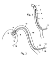
- Fig. 2 shows a further application example of a device according to the invention, which is formed in this case by a cardiac catheter pump 6.
- This has a housing 7, in which a rotor with a hub 8 and conveying elements 9, 10 is housed in the form of conveying blades.
- the pump typically has a larger diameter during operation than during transport to give it the required effectiveness. For this reason, the pump is radially compressed prior to introduction into a blood vessel 11, through which it is to be pushed into a heart chamber 12. Then it is introduced through a lock 13 into the blood vessel 10 and pushed through to the heart chamber 12. Then the pump, for example, the rotor and the pump housing, together or in each case radially expanded.
- the invention can generate or assist the expansion movement per se. However, it can also act only after the expansion movement in that, for example, the rotor or the pump housing is stiffened in the expanded position and thus stabilized.
- the pump is operable at high speeds and under high mechanical load by the motor 14 drives the shaft 15 with, for example, 10,000 rpm.
- the erection of the individual elements of the pump 6 after being brought to the place of use in the heart chamber 12 can be done, for example, by causing the rotor 8, 9, 10 to rotate and either by the centrifugal forces acting or by the Flugi forces that coincide with the Set rotation, or set up by both together becomes.
- mechanical devices such as trains or pressure devices can be provided, which are actuated along the hollow catheter 16 from outside the patient's body and which act on the pump head and there cause or support a corresponding expansion movement.
- Other mechanisms are also possible through which expansion can be achieved.
- Fig. 3 shows a view of a rotor with blades or rotor blades 9 ', 10', which attach to a hub 8 'and in the Fig. 3 are still shown in the transport state in which they are applied radially to the hub 8 '.
- a partial region 17, 18 of each conveying element 9 ', 10' is designed such that it is influenced by certain external influences such as, for example, irradiation with UV light or particle radiation ( ⁇ -, ⁇ -, ⁇ -), electrical and / or magnetic fields , Ultrasound or mechanical stress contracted.
- certain external influences such as, for example, irradiation with UV light or particle radiation ( ⁇ -, ⁇ -, ⁇ -), electrical and / or magnetic fields , Ultrasound or mechanical stress contracted.
- materials for the regions 17, 18, it is possible, for example, to choose self-crosslinking plastics which, on the one hand, harden on crosslinking and on the other hand contract.
- the Fig. 4 shows that by a contraction of the regions 17, 18, the conveying elements 9 ', 10' used in their area more closely to the hub 8 'and thus radially erected, as indicated by the arrow 19.
- This effect is stable and permanent in permanent networking.
- substances that show such a contraction temporarily for example by Effects of magnetostriction or piezo effect.
- the rotor is radially expanded only as long as (or acting only in the transport state to) the corresponding fields act. Otherwise, the rotor will stabilize and the external action may be eliminated without the rotor becoming unstable.
- the entire region of the conveying elements in the region of the hub from a corresponding material, which either contracted or stiffened, wherein the geometry must be selected accordingly in order to achieve an automatic erection of the conveying elements, if not the erection by a other effect, such as manipulation by means of wire drawing or the like is achieved. If the expansion is achieved by other effects, it may be sufficient to stiffen parts of the conveying elements 9 ', 10' or the entire conveying elements, by being made of a corresponding crosslinkable material or a material which stiffens under appropriate action. For example, there are elastomers that react to magnetic fields by stiffening.
- FIG. 5 another embodiment of the invention with a rotor with a hub 8 '' and two conveyor blades 9 '', 10 '' and disposed therein cavities 20, 21 is shown.
- the cavities 20, 21 are connected via a line system with supply lines 22, 23 which extend through the hub 8 '', with a pressure source.
- supply lines 22, 23 which extend through the hub 8 '', with a pressure source.
- Corresponding lines can either through a lumen of the hollow catheter or in addition there inside or outside supplied to the hollow catheter tubes are fed.
- a gas or a liquid can be pressed into the cavities 20, 21, so that the conveying elements 9 '', 10 '', as in Fig. 6 shown, straighten up and tighten.
- a corresponding pressed-in liquid in the cavities 20, 21 is then solidified either by crosslinking or a chemical reaction with another substance, or the properties of the liquid are changed by field effect, which for example in magnetorheological fluids by the action of a magnetic field and corresponding change in viscosity is possible.
- the rotor is stabilized at high viscosity of the liquid.
- a gas is first pressed in, then another substance has to be introduced in order to obtain the stiffening permanently.
- another substance has to be introduced in order to obtain the stiffening permanently.
- the maintenance of, for example, a field may be necessary to obtain the corresponding desired mechanical properties of the rotor.
- the Fig. 7 shows a rotor with two conveying elements in the form of blades 9 ''',10''', wherein each of the conveying elements comprises two stiffening webs 24, 25, 26, 27. These are in the transport state of Fig. 7 still limp, so that the conveyor elements 9 ''',10''' can abut the hub 8 '''.
- the rotor After moving to the site will, as in Fig. 8 indicated by the arrow 28, the rotor is rotated so that the conveyor elements 9 ''',10''' upright by centrifugal force and / or fluid back pressure.
- the reaction may be used to stiffen the ridges 24, 25, 26, 27, either by irradiation as represented by the exposure source 29, which may be replaced by a magnetic or electric field source, or by an ultrasonic source or by an ultrasonic source chemical reaction, which can be triggered or conveyed, for example, by diffusing a substance 30 in which the conveying elements move.
- this substance may be present in human form as part of the blood when the pump is used in human blood. If this substance diffuses into the conveying elements and hits the reinforcing or stiffening webs, then there takes place a hardening reaction that stiffens the conveying elements.
- the Fig. 9 schematically shows a single conveying element 31 with a cavity 32 which is partially filled with a liquid 33.
- a gas flows through a lumen in the hub 8 '''' and the conveying element 31 into the cavity 32 and there with the liquid 33 to form a Foam reacts.
- an expansion takes place, through which the cavity 32 is pressurized and inflated.
- the foam 36 either stiffened by the reaction or by a subsequent hardening and thus stabilizes the conveying element 31, as in Fig. 10 shown.
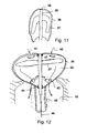
- Fig. 11 shows in the transport state, a pump with a pump housing 36 in the form of a membrane which has collapsed and closely surrounds the likewise compressed rotor with the conveyor blades 37.
- the housing 36 is attached to the end 38 of the hub 39 and is pushed in this state at the end of a hollow catheter through a blood vessel.
- the rotor can be set in rotation slowly, as in the Fig. 12 shown. Due to the centrifugal forces and / or by fluid forces of the blood to be pumped, the conveyor blades 37 are erected, suck blood through openings on the front of the housing 36, indicated by the arrows 40, 41, and thus increase the pressure in the interior of the pump housing 36th the membrane 36 is widened and inflated and tensioned Taut. At the same time, the space for the complete development of the conveying blades 37 opens, so that the rotor can absorb its full number of revolutions. From the interior 42 of the pump housing 36, the blood can then be forced through the openings 43 into the blood vessel 10.
- the pump housing 36 is supported on the distal end 44 of the hollow catheter 45, wherein through the hollow catheter 45 and the drive shaft 46 extends, which ends at the hub 47.
- the hub 47 is usefully mounted rotatably at both ends of the pump housing 36.
- the pump can be stabilized in this state by hardening both the pump housing and the delivery blades. This is done, for example, by irradiation from the outside with UV light, other radiation or ultrasound or by chemical action either by adding a suitable, a reaction to the conveyor elements or on the pump housing in progress substance or by reaction with an already located in the blood to be delivered Substance that acts as a reactant or catalyst.
- a temporary stiffening or increase in viscosity in the case of filling liquids by application of magnetic or electric fields may alternatively be provided.
- Corresponding fields can either be introduced from outside the patient's body or they can be irradiated by appropriate probes, which are brought into the vicinity of the pump can be applied.
- electromagnetic radiation such as light, UV radiation, infrared radiation, shortwave or X-ray radiation is passed to the pump head to cause a curing reaction there.
- electromagnetic radiation such as light, UV radiation, infrared radiation, shortwave or X-ray radiation
- This can be done for example via a suitable light guide, which can be performed, for example, through the hollow catheter.
- Fig. 13 schematically shows a pump head with a housing 36 and conveying blades 37, the reinforcing ribs 48 have. These are typically stiffened to stabilize the operating condition, for example by crosslinking a crosslinkable polymer.
- the Fig. 14 shows the reinforcing webs 48 within the conveying blades 37 in a fractured or broken state, as the pump head together with the housing 36 in the funnel-shaped, distal end of the hollow catheter 49 is retracted by means of the drive shaft 46.
- the retraction can also be done by other means such as parallel to the drive shaft 46 in the hollow catheter 49 extending trains.
- the pump head can be drawn into the hollow catheter without major mechanical resistance and removed together with it from the heart chamber or through the blood vessel out of the patient's body.
- a treatment other than the initial stiffening treatment may also be used.
- embrittlement or breakage by ultrasonic treatment may be provided.
- a temperature reduction for example, by introducing a coolant through the hollow catheter 49 can be accomplished locally, to make the rotor and / or the pump housing to brittle and fragile. It makes the most sense to only break the rotor accordingly and to leave the pump housing intact, so that any resulting fragments of fracture can not get into the bloodstream.
- FIGS. 15 and 16 In the FIGS. 15 and 16 is shown a possible erection mechanism for a rotor after transport and transition to the operating state.
- a rotor is shown with the hub 50 and the conveying blades 51 in the compressed state within the hollow catheter 52 just before it is pushed out in the direction of arrow 53 from the hollow catheter within the heart chamber.
- the pushing out can be done by means of the drive shaft 54 or other not shown wires or trains.
- the rotor is still uncured and movable. If he has moved out of the hollow catheter, so it is alternatively or in addition to other ways of expansion also possible, subsequently the rotor a little way in the direction of arrow 55 in Fig. 16 so that the conveyor blades 51 abut by the abutment at the edge of the distal end of the hollow catheter 52 and are raised radially in the direction of the arrows 56, 57.
- the housing of the pump is disregarded, but this will additionally be provided in the majority of embodiments and surround the rotor.
- the Fig. 17 shows a further embodiment of a rotor with a hub 58, on the conveying blades 59 are attached.
- a rotor with a hub 58 on the conveying blades 59 are attached.
- the rotor or the blades of the rotor are erected.
- the erection wheel 61 is accomplished by pushing by means of a plurality of thrust elements 63, 64 or a hose-like element extending within the hollow catheter 60, which can surround, for example, the drive shaft 65.
- the erecting wheel 61 In the erected state of the rotor, this is then cured, and then the erecting wheel 61 can be retracted into the hollow catheter 60.
- the erecting wheel 61 is provided with large passage openings 66 in order not to affect the flow conditions of the pump or only minimally.
- the process of hardening and / or softening of the device in each case by a brief influence of a pulse, electromagnetic field or a similar effect, so that the respective Impact time is limited to the minimum necessary extent.
- the crystallization process of the liquid can be triggered by a short mechanical impulse, similar to the procedure in so-called heat pads.
- the correspondingly crystallized medium can then be re-liquefied by brief local heat.
- the device according to the invention and the method according to the invention allow, with a technically clear outlay, the influencing of the mechanical properties of elements of a device introduced into a patient's body, especially a blood pump, so that it can be brought into the appropriate form for operation or provided with the required rigidity. without the corresponding mechanical properties already at Insertion into the patient's body would have to be present. As a result, new designs of corresponding devices / pumps are possible.
Abstract
Description
Die Erfindung liegt auf dem Gebiet des Maschinenbaus und der Feinwerktechnik und ist mit besonderem Vorteil bei Vorrichtungen einsetzbar, die in einem Transportzustand an einen Einsatzort befördert und dort in einen Betriebszustand gebracht werden, bevor sie in Gang gesetzt werden.The invention is in the field of mechanical engineering and precision engineering and can be used with particular advantage in devices that are transported in a transport state to a site and there brought into an operating condition before they are set in motion.
Dies ist beispielsweise bei Geräten sinnvoll, die an schwierig zugängliche Orte befördert werden müssen, um dort eingesetzt zu werden, beispielsweise Pumpen oder Bearbeitungswerkzeuge in verwinkelten Schlauch-oder Rohrsystemen.This is useful, for example, in devices that need to be transported to difficult to reach places to be used there, such as pumps or machining tools in winding hose or pipe systems.
Im mikroskopischen Maßstab sind derartige Geräte als mikroinvasive Geräte, beispielsweise Pumpen oder Fräsen in menschlichen oder tierischen Gefäßen, beispielsweise Blutgefäßen oder anderen Körperhohlräumen einsetzbar.On a microscopic scale, such devices are microinvasive devices, such as pumps or milling in human or animal vessels, For example, blood vessels or other body cavities can be used.
Dabei ist es schwierig, diese Geräte durch die körpereigenen Gefäße einzuführen, da hierzu die entsprechenden Maße sehr klein gehalten werden müssen, wobei gleichzeitig im Betrieb größere Abmaße für die Effektivität des Einsatzes sinnvoll sind.It is difficult to introduce these devices through the body's own vessels, as this, the corresponding dimensions must be kept very small, at the same time greater dimensions are useful for the effectiveness of the use in operation.
Auf dem Gebiet der Katheterpumpen, insbesondere der Blutpumpen, sind zur Lösung dieses Problems bereits radial komprimierbare Pumpen vorgeschlagen worden, die während des Transports in einem Transportzustand mit geringer radialer Ausdehnung gehalten werden und die nach dem Einbringen an den Einsatzort, beispielsweise in eine Herzkammer, dort radial expandiert werden können.In the field of catheter pumps, in particular blood pumps, radially compressible pumps have been proposed to solve this problem, which are held during transport in a transport state with small radial extent and after introduction to the site, for example in a ventricle, there can be expanded radially.
Zu diesem Zweck sind aufwendige mechanische Konstruktionen bekannt, die zum Aufrichten von Förderelementen eines Rotors dienen. Zudem ist es oft notwendig, die entsprechenden Förderelemente wie Förderschaufeln im Betrieb zu stabilisieren, da diese beträchtlichen Fluidkräften im Betrieb ausgesetzt sind.For this purpose, complex mechanical structures are known, which serve for erecting conveying elements of a rotor. In addition, it is often necessary to stabilize the corresponding conveyor elements such as conveyor blades in operation, as they are exposed to considerable fluid forces in operation.
Beispielsweise ist ein komprimierbarer Rotor aus der
Zusätzlich zur Komprimierbarkeit des Rotors kann es auch vorteilhaft oder sinnvoll sein, das Pumpengehäuse, das den Rotor umgeben kann, entsprechend komprimierbar auszugestalten.In addition to the compressibility of the rotor, it may also be advantageous or useful to make the pump housing, which can surround the rotor, correspondingly compressible.
Dabei besteht regelmäßig das Problem, dass einerseits die Konstruktion und die Materialien des Rotors im Betrieb stabil sein sollen, um das Fluid bei hohen Drehzahlen zuverlässig zu fördern, und dass andererseits eine gewisse Nachgiebigkeit zumindest von Teilen des Rotors wünschenswert ist, um die zur Kompression des Rotors bzw. der Pumpe notwendigen Kräfte in Grenzen zu halten.There is regularly the problem that on the one hand the construction and the materials of the rotor should be stable in operation to reliably convey the fluid at high speeds, and that on the other hand, a certain flexibility at least of parts of the rotor is desirable to the for compression of Rotor or the pump necessary forces to be limited.
Der vorliegenden Erfindung liegt vor diesem Hintergrund die Aufgabe zugrunde, eine entsprechende Vorrichtung zur mechanischen Einwirkung auf ein Medium, insbesondere eine Fluidpumpe, derart zu gestalten, dass sie sinnvoll von einem Transportzustand in einen Betriebszustand gebracht werden kann, wobei der Transportzustand eine besondere Eignung für den Transport aufweist, während der Betriebszustand sich von diesem unterscheidet und besonders für den Betrieb der Vorrichtung/Pumpe geeignet ist.Against this background, the present invention is based on the object of designing a corresponding device for the mechanical action on a medium, in particular a fluid pump, such that it can usefully be brought from a transport state into an operating state, wherein the transport state is particularly suitable for the Transport, while the operating state is different from this and is particularly suitable for the operation of the device / pump.
Die Aufgabe wird mit den Merkmalen der Erfindung gemäß Patentanspruch 1 gelöst.The object is achieved with the features of the invention according to claim 1.
Dadurch, dass das erste Element aus einem Stoff besteht bzw. mit einem Stoff oder Stoffgemisch gefüllt oder füllbar ist, der/das beim Übergang in den Betriebszustand eine chemische Reaktion, beispielsweise eine Vernetzung oder einen Übergang vom flüssigen Zustand in einen festen Zustand durchläuft und damit wenigstens eine mechanische Eigenschaft ändert, ist es möglich, beispielsweise im Transportzustand des ersten Elementes eine geringere Steifigkeit zu realisieren als im Betriebszustand. Beispielsweise kann das erste Element ein Förderelement, beispielsweise eine Förderschaufel eines Rotors einer Fluidpumpe sein, so dass bei geringerer Steifigkeit das entsprechende Förderelement an eine Nabe anlegbar ist und der entsprechende Rotor damit leicht komprimierbar ist. Der Rotor kann in diesem Zustand auch selbstkomprimierbar sein, dadurch, dass im Ruhezustand die Förderelemente an der Nabe anliegen und diese erst durch Zentrifugalkräfte bei Inbetriebnahme aufgestellt werden.Characterized in that the first element consists of a substance or is filled or fillable with a substance or mixture of substances, which / the transition to the operating state undergoes a chemical reaction, such as a cross-linking or transition from the liquid state to a solid state and thus at least one mechanical property changes, it is possible, for example, in the transport state the first element to realize a lower rigidity than in the operating state. For example, the first element may be a conveying element, for example a conveying blade of a rotor of a fluid pump, so that with lower rigidity the corresponding conveying element can be applied to a hub and the corresponding rotor is thus easily compressible. The rotor can also be self-compressible in this state, characterized in that rest in the idle state, the conveyor elements on the hub and they are placed only by centrifugal forces during commissioning.
Um dann im Betrieb eine höhere Steifigkeit der Förderschaufeln oder Förderelemente zu gewährleisten, ist der Stoff, aus dem die Förderschaufel oder ein Teil der Förderschaufel besteht, derart gewählt, dass er bei Durchlaufen der entsprechenden Reaktion oder des Übergangs, insbesondere des Übergangs in einen anderen Aggregatzustand, beispielsweise einer Kristallisation, eine Erhärtung oder Versteifung erfährt.In order to ensure a higher rigidity of the conveying blades or conveying elements during operation, the substance of which the conveying blade or a part of the conveying blade is selected such that it passes through the corresponding reaction or the transition, in particular the transition to another state of aggregation , For example, a crystallization, a hardening or stiffening experiences.
Es kann auch vorgesehen sein, dass das erste Element, also beispielsweise das Förderelement, Hohlräume aufweist, die mit einem entsprechenden Stoff füllbar sind, beispielsweise über Zuleitungsschläuche, und die danach härtbar, versteifbar oder, wenn es sich um eine Flüssigkeit handelt, in ihrer Viskosität änderbar sind.It can also be provided that the first element, so for example the conveying element, has cavities, which can be filled with a corresponding substance, for example via supply hoses, and then curable, stiffenable or, if it is a liquid, in its viscosity are changeable.
Dabei muss nicht das gesamte Element seine Eigenschaften entsprechend ändern, sondern es genügt beispielsweise, wenn ein Gelenk, das das Förderelement mit einer Nabe verbindet, durch die entsprechende Reaktion versteift wird oder seine Form ändert und dadurch das Förderelement radial expandiert bzw. aufrichtet.In this case, the entire element does not have to change its properties accordingly, but it is sufficient, for example, if a joint which connects the conveying element to a hub is stiffened by the corresponding reaction or its shape changes, thereby radially expanding or erecting the conveying element.
Es kann auch vorgesehen sein, dass das erste Element ein anderes Teil eines Rotors einer Fluidpumpe darstellt oder ein Pumpengehäuse entsprechend in eine Betriebsform oder eine dem Betrieb entsprechende Steifigkeit zu bringen ist.It can also be provided that the first element is another part of a rotor of a fluid pump or a pump housing is to be brought into a corresponding operating form or a stiffness corresponding to the operation.
Auch in diesem Fall wie bei einer entsprechenden Anwendung bei einem Rotor können Hohlräume vorgesehen sein, die beispielsweise unter Druck mit einem Fluid gefüllt und damit aufgepumpt werden können, um dem entsprechenden ersten Element eine gewünschte Form zu geben, woraufhin der Stoff gehärtet oder versteift werden kann, um diese Form stabil zu erhalten.Also in this case, as in a corresponding application to a rotor cavities may be provided which can be filled, for example, under pressure with a fluid and thus pumped to give the corresponding first element a desired shape, after which the substance can be cured or stiffened to keep this shape stable.
Durch die entsprechende Reaktion kann alternativ zur Steifigkeit auch eine andere mechanische Eigenschaft wie die geometrische Form oder Größe geändert werden. Beispielsweise kann ein Teil einer Förderschaufel durch die Reaktion verkürzt oder verlängert werden und dadurch, also mittels Hebelkräften, die Förderschaufel aufrichten oder versteifen.As a result of the corresponding reaction, another mechanical property, such as the geometric shape or size, can be changed as an alternative to rigidity. For example, a part of a bucket can be shortened or lengthened by the reaction and thereby, ie by means of leverage, erect or stiffen the bucket.
Der Stoff, aus dem das erste Element teilweise besteht oder mit dem es füllbar ist, kann beispielsweise ein härtbares Material, insbesondere einen härtbaren Kunststoff aufweisen.The substance of which the first element partially consists or with which it can be filled can, for example, comprise a curable material, in particular a hardenable plastic.
Eine Härtung kann zum Übergang in den Betriebszustand beispielsweise durch Temperatur- bzw. Druckeinwirkung, elektrische und/oder magnetische Felder bzw. Impulse, Strahlung (IR- bzw. UV-Licht-, α-, β-, γ-), mechanische Einwirkung, z. B. Ultraschall oder Erschütterung erfolgen, oder auch durch Kontakt mit einem weiteren Stoff oder durch Initialisierung einer Kristallisation bei einem flüssigen Stoff herbeigeführt werden.Curing can be used for the transition to the operating state, for example by temperature or pressure, electrical and / or magnetic fields or pulses, radiation (IR or UV light, α-, β-, γ-), mechanical action, z. B. ultrasound or vibration, or by contact with a further substance or by initialization of a crystallization in a liquid substance are brought about.
Der weitere Stoff kann dabei ein echter Reaktionspartner sein, der bei der Reaktion ebenfalls reagiert und eine Umwandlung erfährt, oder ein Katalysator bzw. Enzym, der bei Zugabe zu einer Beschleunigung der Reaktion führt.The further substance may be a true reaction partner, which also reacts in the reaction and undergoes a conversion, or a catalyst or enzyme, which leads to an acceleration of the reaction when added.
Der weitere Stoff kann beispielsweise in dem Medium enthalten sein, auf das die Vorrichtung einwirken soll, beispielsweise in der Körperflüssigkeit, in der eine entsprechende Fluidpumpe betrieben werden soll. In diesem Fall kann die Körperflüssigkeit beim Einbringen der Vorrichtung in einen Körper eindiffundieren, und die gewünschte Reaktion kann dann vor Aufnahme des Betriebs, entweder selbsttätig oder initiiert oder unterstützt durch zusätzliche Maßnahmen, ablaufen.The further substance may, for example, be contained in the medium on which the device is to act, for example in the body fluid in which a corresponding fluid pump is to be operated. In this case, the bodily fluid may diffuse into a body upon insertion of the device, and the desired reaction may then proceed prior to commencement of operation, either automatically or initiated or assisted by additional measures.
Durch die Erfindung gelingt es, für den Betrieb der Vorrichtung, beispielsweise der Pumpe, mechanische Eigenschaften zu gewährleisten, die während des Transports zur Einsatzstelle unvorteilhaft wären und durch die Erfindung vermieden werden können. Diese Eigenschaften werden erst nach dem Verbringen an den Einsatzort mit Ablauf der entsprechenden Reaktionen erreicht. Die entsprechenden Reaktionen können reversibel, jedoch auch irreversibel sein.The invention makes it possible to ensure mechanical properties for the operation of the device, for example the pump, which would be disadvantageous during transport to the point of use and can be avoided by the invention. These properties are achieved only after the transfer to the site with the end of the corresponding reactions. The corresponding reactions can be reversible, but also irreversible.
Eine vorteilhafte Ausgestaltung der Erfindung sieht weiterhin vor, dass durch eine fortgesetzte oder weitere Reaktion das erste Element reversibel oder irreversibel in einen Zustand überführbar ist, in dem die Vorrichtung transportierbar ist oder in dem es durch mechanisches Zerbrechen in einen Transportzustand gebracht werden kann.An advantageous embodiment of the invention further provides that by a continued or further reaction, the first element is reversibly or irreversibly in a state can be converted, in which the device is transportable or in which it can be brought into a transport state by mechanical breaking.
Beispielsweise kann durch Fortsetzung der Reaktion, die vor Erreichen des Betriebszustandes durchlaufen wurde, eine weitere Änderung der mechanischen Eigenschaften stattfinden, z. B. eine Versprödung des Stoffes, aus dem das erste Element ganz oder teilweise besteht. Diese Versprödung kann so weit gehen, dass die entsprechenden Teile von selbst brechen oder zumindest leicht gebrochen werden können, um wieder einen geeigneten Transportzustand zum Rücktransport der Vorrichtung/Fluidpumpe zu erreichen. Es kann jedoch auch eine andere Reaktion vorgesehen sein, um das entsprechende gewünschte Ergebnis zu erzielen.For example, by continuing the reaction which has been carried out before reaching the operating state, a further change in the mechanical properties take place, for. As an embrittlement of the substance from which the first element consists entirely or partially. This embrittlement can go so far that the corresponding parts can break on their own or at least be easily broken in order to again achieve a suitable transport state for the return transport of the device / fluid pump. However, another reaction may be provided to achieve the desired result desired.
Zusätzlich zu der erfindungsgemäßen Vorrichtung bezieht sich die Erfindung auch auf ein Verfahren zum Betrieb einer entsprechenden Vorrichtung, bei dem zunächst die Vorrichtung in einen Körper eines Lebewesens eingeführt wird, wobei darauf der Stoff / das Stoffgemisch des ersten Elementes einer Reaktion, insbesondere Vernetzung, oder eine Kristallisation aus der flüssigen Phase erfährt und wobei darauf die Vorrichtung in Gang gesetzt wird.In addition to the device according to the invention, the invention also relates to a method for operating a corresponding device, in which first the device is introduced into a body of a living being, thereon the substance / mixture of the first element of a reaction, in particular crosslinking, or a Crystallization from the liquid phase experiences and whereupon the device is set in motion.
Durch eine derartige Handhabung wird die Vorrichtung im Transportzustand zunächst innerhalb eines Körpers eines Lebewesens an den Einsatzort gebracht und erst dort bezüglich der mechanischen Eigenschaften in den Betriebszustand und damit eine für den Betrieb effiziente Form gebracht.By such handling, the device is first brought in the transport state within a body of a living being to the site and only there in terms of mechanical properties in the operating condition and thus brought an efficient for operation form.
Besonders vorteilhaft kann vorgesehen sein, dass vor der Reaktion der oder ein Stoff in wenigstens einen Hohlraum des ersten Elementes eingeführt wird. Beispielsweise kann ein Hohlraum oder eine Reihe von Hohlräumen, die beispielsweise durch Blasen eines Schaumstoffs, aus dem das erste Element besteht, gebildet sein können, über Schläuche mit einem Stoff gefüllt, der entweder selbst eine Reaktion zur Änderung seiner mechanischen Eigenschaften durchlaufen kann oder der in den Hohlräumen auf einen weiteren Stoff trifft, mit dem er entsprechend reagiert oder wobei einer der Stoffe als Katalysator für die Reaktion dient.Particularly advantageously, it can be provided that, prior to the reaction, the substance or a substance is introduced into at least one cavity of the first element. For example, a cavity or a series of cavities, which may be formed, for example, by blowing a foam of which the first element is made, filled via hoses with a substance that can either undergo a reaction itself to change its mechanical properties or in the cavities meets another substance, with which he reacts accordingly or wherein one of the substances serves as a catalyst for the reaction.
Die eigentliche Reaktion kann dabei durch entsprechende Einflussnahme von außen initiiert, unterstützt oder durchgeführt werden, wobei hierzu beispielsweise Strahlung, Temperaturveränderung, mechanische Einwirkung, wie beispielsweise Ultraschall, oder die Einwirkung durch elektrische und/oder magnetische Felder dienen kann.The actual reaction can be initiated, supported or carried out by appropriate influence from outside, for example, radiation, temperature change, mechanical action, such as ultrasound, or the action of electrical and / or magnetic fields can serve.
Die Erfindung bezieht sich zudem auf eine Vorrichtung zur mechanischen Einwirkung auf ein Medium mit wenigstens einem ersten Element, das durch Änderung wenigstens einer mechanischen Eigenschaft von einem Transportzustand in einen Betriebszustand gebracht werden kann, wobei das erste Element wenigstens teilweise aus einem Stoff besteht oder mit einem Stoff oder Stoffgemisch füllbar ist, der/das, solange er/es einer Bestrahlung, einem elektrischen und/oder magnetischen Feld ausgesetzt ist, gegenüber dem Zustand ohne derartige Einwirkung geänderte mechanische Eigenschaften, insbesondere bezüglich Steifigkeit, Viskosität, Größe und/oder Form, aufweist.The invention also relates to a device for mechanical action on a medium having at least one first element, which can be brought by changing at least one mechanical property of a transport state to an operating state, wherein the first element consists at least partially of a substance or with a Substance or substance mixture is fillable, the / as long as he / she is exposed to radiation, an electric and / or magnetic field, compared to the state without such action modified mechanical properties, in particular with regard to stiffness, viscosity, size and / or shape ,
Beispiele für eine derartige Veränderung der mechanischen Eigenschaften durch Felder sind der Piezoeffekt und Magnetostriktion bzw. bei Flüssigkeiten ein magnetorheologischer Effekt bzw. die Änderung der Viskosität durch elektrische Feldeinwirkung.Examples of such a change of the mechanical properties by fields are the piezoelectric effect and magnetostriction or, in the case of liquids, a magnetorheological effect or the change in viscosity due to electric field effect.
Ein entsprechendes erfindungsgemäßes Verfahren zum Betrieb einer solchen Vorrichtung sieht vor, dass die Vorrichtung nach ihrer Einführung in einen Körper eines Lebewesens der entsprechenden Einwirkung ausgesetzt wird, um die Vorrichtung funktionsfähig zu machen. Während des Betriebes der Vorrichtung/Fluidpumpe muss die Einwirkung aufrechterhalten werden. Es muss dabei weder eine reversible noch eine irreversible chemische Reaktion stattfinden, sondern es wird lediglich abhängig von der Einwirkung ein anderer mechanischer Zustand des Stoffs eingenommen.A corresponding method according to the invention for operating such a device provides that after its introduction into a body of a living being the device is subjected to the corresponding action in order to make the device functional. During operation of the device / fluid pump, the action must be maintained. Neither a reversible nor an irreversible chemical reaction has to take place, but only a different mechanical state of the substance is assumed depending on the action.
In einer Abwandlung kann die Erfindung auch so ausgestaltet sein, dass die entsprechende Einwirkung im Transportzustand aufrechterhalten wird und zum erreichen bzw. während des Betriebszustandes entfernt wird bzw. wegfällt.In a modification, the invention may also be designed such that the corresponding action in the transport state is maintained and is removed or removed for reaching or during the operating state.
Im Folgenden wird die Erfindung anhand mehrerer Ausführungsbeispiele in einer Zeichnung gezeigt und nachfolgend beschrieben.In the following the invention will be shown with reference to several embodiments in a drawing and described below.
Dabei zeigt
- Fig. 1
- schematisch in einem Längsschnitt ein Blutgefäß mit einem in dieses eingeführten Hohlkatheter und einer Fräse,
- Fig. 2
- schematisch ein in eine Herzkammer mündendes Blutgefäß, durch das ein Hohlkatheter mit einer Herzpumpe eingeschoben ist,
- Fig. 3
- einen Rotor einer Pumpe im Transportzustand,
- Fig. 4
- den Rotor aus
Fig. 3 im Betriebszustand, - Fig. 5
- einen weiteren Rotor im Transportzustand,
- Fig. 6
- den weiteren Rotor aus
Fig. 5 im Betriebszustand, - Fig. 7
- einen dritten Rotor im Transportzustand,
- Fig. 8
- den Rotor aus
Fig. 7 im Betriebszustand während des Versteifungsprozesses, - Fig. 9
- ein Detail eines Rotors mit einem Förderelement, das einen Hohlraum aufweist, der teilweise gefüllt ist,
- Fig. 10
- das Detail aus
Fig. 9 , wobei der Hohlraum vollständig ausgefüllt ist, - Fig. 11
- schematisch eine Ansicht eines Rotors im Transportzustand mit einem Pumpengehäuse, das zusammengefallen ist,
- Fig. 12
- die Pumpe aus
Fig. 11 im Betriebszustand, - Fig. 13
- einen Rotor im Betriebszustand in versteifter Form mit einem im Betriebszustand befindlichen Gehäuse einer Pumpe,
- Fig. 14
- die Teile der Pumpe aus
Fig. 13 nach einer weiteren Behandlung, die das Brechen der Förderelemente ermöglicht, - Fig. 15
- einen Rotor mit Förderelementen, der durch einen Hohlkatheter im Transportzustand durchgeschoben wird,
- Fig. 16
- den Rotor aus
Fig. 15 , der durch Zurückziehen der Nabe in den Hohlkatheter aufgerichtet wird, - Fig. 17
- einen Rotor, der durch Verschieben eines Stützrades mittels Schubelementen aufgerichtet wird, sowie
- Fig. 18
- eine Ansicht des Schubrades.
- Fig. 1
- schematically in a longitudinal section a blood vessel with a hollow catheter inserted into this and a milling cutter,
- Fig. 2
- schematically a blood vessel opening into a heart chamber, through which a hollow catheter is inserted with a heart pump,
- Fig. 3
- a rotor of a pump in the transport state,
- Fig. 4
- off the rotor
Fig. 3 in the operating state, - Fig. 5
- another rotor in the transport state,
- Fig. 6
- the other rotor
Fig. 5 in the operating state, - Fig. 7
- a third rotor in the transport state,
- Fig. 8
- off the rotor
Fig. 7 in the operating state during the stiffening process, - Fig. 9
- a detail of a rotor with a conveyor element having a cavity which is partially filled,
- Fig. 10
- the detail
Fig. 9 wherein the cavity is completely filled, - Fig. 11
- 3 is a schematic view of a rotor in the transport state with a pump housing that has collapsed;
- Fig. 12
- the pump off
Fig. 11 in the operating state, - Fig. 13
- a rotor in the operating state in a stiffened form with a housing in the operating state of a pump,
- Fig. 14
- the parts of the pump
Fig. 13 after a further treatment which makes it possible to break the conveying elements, - Fig. 15
- a rotor with conveying elements, which is pushed through a hollow catheter in the transport state,
- Fig. 16
- off the rotor
Fig. 15 which is erected by retracting the hub into the hollow catheter, - Fig. 17
- a rotor, which is erected by moving a support wheel by means of pushing elements, as well as
- Fig. 18
- a view of the push wheel.
Die Fräse 1 wird vorteilhaft zunächst in einem Transportzustand in das Blutgefäß 3 eingeführt, beispielsweise in radial komprimierter Form, und dann vor Ort in einen Betriebszustand überführt, der beispielsweise dadurch unterschiedlich zum Transportzustand sein kann, dass der Fräskopf radial vergrößert oder versteift wird. Die Erfindung löst das Problem, diese Änderung der mechanischen Eigenschaften der Fräse nach dem Durchlaufen des Transportweges in günstiger Form zu bewerkstelligen.The mill 1 is advantageously first introduced into the
Die Pumpe weist typischerweise im Betrieb einen größeren Durchmesser auf als während des Transportes, um ihr die erforderliche Effektivität zu verleihen. Aus diesem Grund wird die Pumpe vor dem Einbringen in ein Blutgefäß 11, durch das sie in eine Herzkammer 12 geschoben werden soll, radial komprimiert. Dann wird sie durch eine Schleuse 13 in das Blutgefäß 10 eingebracht und bis zur Herzkammer 12 durchgeschoben. Darauf wird die Pumpe, beispielsweise der Rotor und das Pumpengehäuse, gemeinsam oder jeweils für sich radial expandiert. Die Erfindung kann die Expansionsbewegung an sich erzeugen oder unterstützen. Sie kann jedoch auch erst nach der Expansionsbewegung dadurch wirken, dass beispielsweise der Rotor oder das Pumpengehäuse in der expandierten Stellung versteift und damit stabilisiert wird.The pump typically has a larger diameter during operation than during transport to give it the required effectiveness. For this reason, the pump is radially compressed prior to introduction into a blood vessel 11, through which it is to be pushed into a
Danach ist die Pumpe mit hohen Drehzahlen und unter hoher mechanischer Belastung betreibbar, indem der Motor 14 die Welle 15 mit beispielsweise 10000 U/min antreibt.Thereafter, the pump is operable at high speeds and under high mechanical load by the
Das Aufrichten der einzelnen Elemente der Pumpe 6 nach dem Verbringen an den Einsatzort in der Herzkammer 12 kann beispielsweise dadurch geschehen, dass der Rotor 8, 9, 10 in Rotation versetzt wird und entweder durch die wirkenden Zentrifugalkräfte oder durch die Fluidgegenkräfte, die sich mit der Drehung einstellen, oder durch beides gemeinsam aufgerichtet wird. Zudem oder alternativ können auch mechanische Vorrichtungen wie beispielsweise Züge oder Druckeinrichtungen vorgesehen sein, die entlang des Hohlkatheters 16 von außerhalb des Patientenkörpers betätigbar sind und die auf den Pumpenkopf wirken und dort eine entsprechende Expansionsbewegung verursachen oder unterstützen. Es sind auch andere Mechanismen möglich, über die auf eine Expansion hingewirkt werden kann. Diese werden beispielhaft anhand der übrigen Figuren erläutert.The erection of the individual elements of the
Jeweils ein Teilbereich 17, 18 jedes Förderelementes 9', 10' ist derart gestaltet, dass er sich durch bestimmte äußere Einflüsse wie beispielsweise Bestrahlung mit UV-Licht oder Teilchenstrahlung (α-, β-, γ-), elektrische und/oder magnetische Felder, Ultraschall oder mechanische Belastung kontrahiert. Es können als Materialien für die Bereiche 17, 18 beispielsweise selbstvernetzende Kunststoffe gewählt werden, die bei der Vernetzung einerseits erhärten und sich andererseits zusammenziehen.In each case, a
Die
Es ist auch denkbar, den gesamten Bereich der Förderelemente im Bereich der Nabe aus einem entsprechenden Material herzustellen, das sich entweder kontrahiert oder versteift, wobei die Geometrie entsprechend gewählt werden muss, um eine selbsttätige Aufrichtung der Förderelemente zu erreichen, wenn nicht die Aufrichtung durch einen anderen Effekt, beispielsweise Manipulation mittels Drahtzügen oder Ähnlichem erreicht wird. Wird die Expansion durch andere Effekte erreicht, so kann es ausreichen, Teile der Förderelemente 9', 10' oder die gesamten Förderelemente zu versteifen, indem sie aus einem entsprechenden vernetzbaren Material oder einem Material, das sich unter entsprechender Einwirkung versteift, hergestellt werden. Es existieren beispielsweise Elastomere, die auf Magnetfelder durch Versteifung reagieren.It is also conceivable to produce the entire region of the conveying elements in the region of the hub from a corresponding material, which either contracted or stiffened, wherein the geometry must be selected accordingly in order to achieve an automatic erection of the conveying elements, if not the erection by a other effect, such as manipulation by means of wire drawing or the like is achieved. If the expansion is achieved by other effects, it may be sufficient to stiffen parts of the conveying elements 9 ', 10' or the entire conveying elements, by being made of a corresponding crosslinkable material or a material which stiffens under appropriate action. For example, there are elastomers that react to magnetic fields by stiffening.
In der
Die Hohlräume 20, 21 sind über ein Leitungssystem mit Zuleitungen 22, 23, die durch die Nabe 8'' verlaufen, mit einer Druckquelle verbunden. Entsprechende Leitungen können entweder durch ein Lumen des Hohlkatheters oder durch zusätzlich dort innen oder außen am Hohlkatheter angeordnete Schläuche gespeist werden.The
Zum Aufrichten der Förderelemente 9'', 10'' kann beispielsweise ein Gas oder eine Flüssigkeit in die Hohlräume 20, 21 eingepresst werden, so dass die Förderelemente 9'', 10'' sich, wie in
Wird zunächst ein Gas eingepresst, so muss darauf ein weiterer Stoff eingebracht werden, um die Versteifung dauerhaft zu erhalten. Es können beispielsweise auch mehrere Stoffe in Form von Flüssigkeiten und/oder Gasen eingebracht werden, die entweder miteinander nach dem Zusammentreffen in den Hohlräumen 20, 21 reagieren oder die noch um einen Katalysator ergänzt werden, sobald die Förderelemente 9'', 10'' aufgerichtet sind, um die Reaktion zu beschleunigen. Wird durch die äußere Einwirkung eine irreversible Reaktion ausgelöst, so kann die Einwirkung nach der Versteifung des Rotors entfallen. Andererseits kann auch die Aufrechterhaltung beispielsweise eines Feldes notwendig sein, um die entsprechenden gewünschten mechanischen Eigenschaften des Rotors zu erhalten.If a gas is first pressed in, then another substance has to be introduced in order to obtain the stiffening permanently. For example, it is also possible to introduce a plurality of substances in the form of liquids and / or gases which either react with one another after the meeting in the
Es kann das Einpressen von Gas in die Hohlräume auch ausschließlich zum Aufrichten der Förderelemente genutzt werden, wenn danach andere Elemente des Rotors zur Stabilisierung dieses Zustands versteift werden.It can also be used exclusively for erecting the conveying elements, the injection of gas into the cavities, if thereafter, other elements of the rotor to stabilize this state are stiffened.
Die
Nach dem Verbringen an den Einsatzort wird, wie in
Die
Zur Aufrichtung und/oder Versteifung des Förderelementes 31 ist vorgesehen, dass entlang der Pfeile 34, 35 ein Gas durch ein Lumen in der Nabe 8'''' und das Förderelement 31 in den Hohlraum 32 einströmt und dort mit der Flüssigkeit 33 unter Bildung eines Schaumstoffs reagiert. Hierdurch und durch die entsprechende Reaktion findet eine Expansion statt, durch die der Hohlraum 32 unter Druck gesetzt und aufgeblasen wird. Gleichzeitig versteift sich der Schaumstoff 36 entweder durch die Reaktion oder durch eine nachfolgende Härtung und stabilisiert somit das Förderelement 31, wie in der
Ist der Pumpenkopf bei der Anwendung als Herzpumpe durch den Aortenbogen durch- und in eine Herzkammer eingeschoben, so kann der Rotor langsam in Drehung versetzt werden, wie in der
Das Pumpengehäuse 36 ist dabei auf dem distalen Ende 44 des Hohlkatheters 45 abgestützt, wobei durch den Hohlkatheter 45 auch die Antriebswelle 46 verläuft, die an der Nabe 47 endet. Die Nabe 47 ist sinnvollerweise an beiden Enden des Pumpengehäuses 36 drehbar gelagert.The
Ist der Betriebszustand durch völlige Entfaltung des Rotors bzw. der Förderschaufeln 37 und Aufpumpen des Pumpengehäuses 36 erreicht, so kann die Pumpe in diesem Zustand durch Härten sowohl des Pumpengehäuses als auch der Förderschaufeln stabilisiert werden. Dies geschieht beispielsweise durch Bestrahlung von außen mit UV-Licht, einer anderen Strahlung oder Ultraschall oder durch chemische Einwirkung entweder durch Zugabe eines geeigneten, eine Reaktion an den Förderelementen oder am Pumpengehäuse in Gang setzenden Stoffes oder durch Reaktion mit einem ohnehin im zu fördernden Blut befindlichen Stoff, der als Reaktionspartner oder Katalysator wirkt.If the operating state is achieved by complete deployment of the rotor or of the
Auch hier kann alternativ dazu eine vorübergehende Versteifung oder Erhöhung einer Viskosität im Falle von Füllflüssigkeiten durch Anwendung von magnetischen oder elektrischen Feldern vorgesehen sein.Again, a temporary stiffening or increase in viscosity in the case of filling liquids by application of magnetic or electric fields may alternatively be provided.
Entsprechende Felder können entweder von außerhalb des Patientenkörpers eingebracht bzw. eingestrahlt werden oder sie können durch entsprechende Sonden, die in die Nähe der Pumpe gebracht werden, appliziert werden.Corresponding fields can either be introduced from outside the patient's body or they can be irradiated by appropriate probes, which are brought into the vicinity of the pump can be applied.
Es ist auch für sämtliche in dieser Anmeldung dargestellten Ausführungsformen sowie auch davon unabhängig möglich, dass beispielsweise Elektromagnetische Strahlung wie zum Beispiel Licht, UV-Strahlung, Infrarotstrahlung, Kurzwellen oder Röntgenstrahlung zum Pumpenkopf geleitet wird, um dort eine Härtungsreaktion hervorzurufen. Dies kann zum Beispiel über einen geeigneten Lichtleiter, der beispielsweise durch den Hohlkatheter geführt werden kann, erfolgen.It is also possible for all embodiments shown in this application as well as independently thereof, for example, that electromagnetic radiation such as light, UV radiation, infrared radiation, shortwave or X-ray radiation is passed to the pump head to cause a curing reaction there. This can be done for example via a suitable light guide, which can be performed, for example, through the hollow catheter.
Um die Probleme zu lösen, die bei der Entnahme des Pumpenkopfes nach der Behandlung bei einem Patienten auftreten können, ist es notwendig, die Förderschaufeln 37 zu komprimieren. Dies kann beispielsweise dadurch geschehen, dass durch eine Strahlungsquelle 49 der Rotor weiter bestrahlt wird, so dass sich die Härtung durch weitere Vernetzung bis zur Versprödung fortsetzt. Sind die Versteifungsstege 48 versprödet, so können sie von selbst brechen oder einfach beim Entnehmen der Pumpe durch Zurückziehen des Pumpenkopfes in den Hohlkatheter 49 gebrochen werden.In order to solve the problems that may arise when removing the pump head after treatment in a patient, it is necessary to compress the conveying
Die
Auf die beschriebene Weise kann der Pumpenkopf ohne größeren mechanischen Widerstand in den Hohlkatheter eingezogen und zusammen mit diesem aus der Herzkammer bzw. durch das Blutgefäß hindurch aus dem Patientenkörper entfernt werden.In the manner described, the pump head can be drawn into the hollow catheter without major mechanical resistance and removed together with it from the heart chamber or through the blood vessel out of the patient's body.
Alternativ zur Fortsetzung des Härtungsprozesses, der nach dem Transport zur Versteifung des Rotors genutzt wurde, bis zur Versprödung kann auch eine Behandlung erfolgen, die von der anfänglichen Versteifungsbehandlung unterschiedlich ist. Beispielsweise kann eine Versprödung oder ein Brechen durch Ultraschallbehandlung vorgesehen sein. Auch eine Temperaturabsenkung beispielsweise durch Einbringen eines Kühlmittels durch den Hohlkatheter 49 kann lokal bewerkstelligt werden, um den Rotor und/oder das Pumpengehäuse zu verspröden und bruchempfindlich zu machen. Am sinnvollsten ist dabei, lediglich den Rotor entsprechend zu brechen und das Pumpengehäuse intakt zu lassen, damit eventuell entstehende Bruchsplitter nicht in die Blutbahn gelangen können.As an alternative to continuing the hardening process, which was used after transport to stiffen the rotor, to embrittlement, a treatment other than the initial stiffening treatment may also be used. For example, embrittlement or breakage by ultrasonic treatment may be provided. Also, a temperature reduction, for example, by introducing a coolant through the
In den
In
Die
Im aufgerichteten Zustand des Rotors wird dieser dann gehärtet, und danach kann das Aufrichtrad 61 in den Hohlkatheter 60 zurückgezogen werden. Das Aufrichtrad 61 ist mit großen Durchgangsöffnungen 66 versehen, um die Strömungsverhältnisse der Pumpe nicht oder nur minimal zu beeinträchtigen.In the erected state of the rotor, this is then cured, and then the erecting
In Ergänzung aller oben genannten Beispiele und auch als eigenständige Erfindung anwendbar ist es darüber hinaus auch möglich, den Vorgang des Härtens und/oder des Erweichens der Vorrichtung jeweils durch eine kurzzeitige Einwirkung eines Impulses, elektromagnetischen Feldes oder eines ähnlichen Effektes hervorzurufen, so dass die jeweilige Einwirkdauer auf das minimal notwendige Ausmaß beschränkt ist. So kann beispielsweise der Kristallisationsprozess der Flüssigkeit durch einen kurzen mechanischen Impuls ausgelöst werden, ähnlich dem Vorgehen bei sogenannten Wärmekissen. Das entsprechend kristallisierte Medium kann dann durch kurzzeitige lokale Wärmeeinwirkung wieder verflüssigt werden. Durch Versetzen des Mediums mit beispielsweise Metallpartikeln, die in einem entsprechenden Feld angeregt werden, könnte die Wärmeeinwirkung soweit lokal begrenzt werden, dass eine Schädigung des umgebenden Gewebes auf ein unschädliches Maß reduziert bzw. ganz vermieden wird.In addition to all the above examples and also applicable as an independent invention, it is also possible to cause the process of hardening and / or softening of the device in each case by a brief influence of a pulse, electromagnetic field or a similar effect, so that the respective Impact time is limited to the minimum necessary extent. Thus, for example, the crystallization process of the liquid can be triggered by a short mechanical impulse, similar to the procedure in so-called heat pads. The correspondingly crystallized medium can then be re-liquefied by brief local heat. By displacing the medium with, for example, metal particles which are excited in a corresponding field, the effect of heat could be localized so far that damage to the surrounding tissue is reduced to a harmless level or avoided altogether.
Die erfindungsgemäße Vorrichtung und die erfindungsgemäßen Verfahren erlauben mit technisch übersichtlichem Aufwand die Beeinflussung der mechanischen Eigenschaften von Elementen einer in einen Patientenkörper eingebrachten Vorrichtung, speziell einer Blutpumpe, so dass diese in die geeignete Form für den Betrieb gebracht oder mit der erforderlichen Steifigkeit versehen werden kann, ohne dass die entsprechenden mechanischen Eigenschaften schon beim Einführen in den Patientenkörper vorhanden sein müssten. Dadurch werden neue Aufbauformen entsprechender Vorrichtungen/Pumpen möglich.The device according to the invention and the method according to the invention allow, with a technically clear outlay, the influencing of the mechanical properties of elements of a device introduced into a patient's body, especially a blood pump, so that it can be brought into the appropriate form for operation or provided with the required rigidity. without the corresponding mechanical properties already at Insertion into the patient's body would have to be present. As a result, new designs of corresponding devices / pumps are possible.
Claims (15)
Priority Applications (9)
| Application Number | Priority Date | Filing Date | Title |
|---|---|---|---|
| EP10075103A EP2363157A1 (en) | 2010-03-05 | 2010-03-05 | Device for exerting mechanical force on a medium, in particular fluid pump |
| DE112011100800T DE112011100800T5 (en) | 2010-03-05 | 2011-03-02 | Pump or tiller for operation in a fluid |
| CN201180012576.4A CN102791303B (en) | 2010-03-05 | 2011-03-02 | The pump operated in a fluid or rotating knife |
| PCT/EP2011/001125 WO2011107296A1 (en) | 2010-03-05 | 2011-03-02 | Pump or rotary cutter for operation in a fluid |
| US13/261,423 US9217442B2 (en) | 2010-03-05 | 2011-03-02 | Pump or rotary cutter for operation in a fluid |
| US14/942,158 US9907891B2 (en) | 2010-03-05 | 2015-11-16 | Pump or rotary cutter for operation in a fluid |
| US15/873,294 US10413646B2 (en) | 2010-03-05 | 2018-01-17 | Pump or rotary cutter for operation in a fluid |
| US16/532,553 US11040187B2 (en) | 2010-03-05 | 2019-08-06 | Pump or rotary cutter for operation in a fluid |
| US17/308,094 US20210346673A1 (en) | 2010-03-05 | 2021-05-05 | Pump or rotary cutter for operation in a fluid |
Applications Claiming Priority (1)
| Application Number | Priority Date | Filing Date | Title |
|---|---|---|---|
| EP10075103A EP2363157A1 (en) | 2010-03-05 | 2010-03-05 | Device for exerting mechanical force on a medium, in particular fluid pump |
Publications (1)
| Publication Number | Publication Date |
|---|---|
| EP2363157A1 true EP2363157A1 (en) | 2011-09-07 |
Family
ID=42269499
Family Applications (1)
| Application Number | Title | Priority Date | Filing Date |
|---|---|---|---|
| EP10075103A Withdrawn EP2363157A1 (en) | 2010-03-05 | 2010-03-05 | Device for exerting mechanical force on a medium, in particular fluid pump |
Country Status (5)
| Country | Link |
|---|---|
| US (5) | US9217442B2 (en) |
| EP (1) | EP2363157A1 (en) |
| CN (1) | CN102791303B (en) |
| DE (1) | DE112011100800T5 (en) |
| WO (1) | WO2011107296A1 (en) |
Cited By (12)
| Publication number | Priority date | Publication date | Assignee | Title |
|---|---|---|---|---|
| WO2013082053A1 (en) * | 2011-11-28 | 2013-06-06 | MI-VAD, Inc. | Ventricular assist device and method |
| WO2015055515A1 (en) * | 2013-10-14 | 2015-04-23 | Ecp Entwicklungsgesellschaft Mbh | Method for operating a supply device which supplies a liquid to a channel, and supply device, hollow catheter, and catheter pump |
| KR20160078397A (en) * | 2013-11-01 | 2016-07-04 | 이씨피 엔트빅클룽스게젤샤프트 엠베하 | Pump, in particular blood pump |
| US10426880B2 (en) | 2014-02-25 | 2019-10-01 | MI-VAD, Inc. | Ventricular assist device and method |
| US10722631B2 (en) | 2018-02-01 | 2020-07-28 | Shifamed Holdings, Llc | Intravascular blood pumps and methods of use and manufacture |
| EP3852245A1 (en) | 2013-10-11 | 2021-07-21 | ECP Entwicklungsgesellschaft mbH | Compressible motor, implanting assembly and method for positioning the motor |
| CN113520568A (en) * | 2021-06-08 | 2021-10-22 | 武汉大学中南医院 | Plasma scalpel |
| US11185677B2 (en) | 2017-06-07 | 2021-11-30 | Shifamed Holdings, Llc | Intravascular fluid movement devices, systems, and methods of use |
| US11511103B2 (en) | 2017-11-13 | 2022-11-29 | Shifamed Holdings, Llc | Intravascular fluid movement devices, systems, and methods of use |
| US11654275B2 (en) | 2019-07-22 | 2023-05-23 | Shifamed Holdings, Llc | Intravascular blood pumps with struts and methods of use and manufacture |
| US11724089B2 (en) | 2019-09-25 | 2023-08-15 | Shifamed Holdings, Llc | Intravascular blood pump systems and methods of use and control thereof |
| US11964145B2 (en) | 2020-07-13 | 2024-04-23 | Shifamed Holdings, Llc | Intravascular blood pumps and methods of manufacture and use |
Families Citing this family (83)
| Publication number | Priority date | Publication date | Assignee | Title |
|---|---|---|---|---|
| US7393181B2 (en) | 2004-09-17 | 2008-07-01 | The Penn State Research Foundation | Expandable impeller pump |
| CN101448535B (en) | 2006-03-23 | 2011-10-19 | 宾州研究基金会 | Heart assist device with expandable impeller pump |
| US8439859B2 (en) | 2007-10-08 | 2013-05-14 | Ais Gmbh Aachen Innovative Solutions | Catheter device |
| US8489190B2 (en) | 2007-10-08 | 2013-07-16 | Ais Gmbh Aachen Innovative Solutions | Catheter device |
| EP2194278A1 (en) | 2008-12-05 | 2010-06-09 | ECP Entwicklungsgesellschaft mbH | Fluid pump with a rotor |
| EP2216059A1 (en) | 2009-02-04 | 2010-08-11 | ECP Entwicklungsgesellschaft mbH | Catheter device with a catheter and an actuation device |
| EP2229965A1 (en) | 2009-03-18 | 2010-09-22 | ECP Entwicklungsgesellschaft mbH | Fluid pump with particular form of a rotor blade |
| EP2246078A1 (en) | 2009-04-29 | 2010-11-03 | ECP Entwicklungsgesellschaft mbH | Shaft assembly with a shaft which moves within a fluid-filled casing |
| EP2248544A1 (en) | 2009-05-05 | 2010-11-10 | ECP Entwicklungsgesellschaft mbH | Fluid pump with variable circumference, particularly for medical use |
| EP2266640A1 (en) | 2009-06-25 | 2010-12-29 | ECP Entwicklungsgesellschaft mbH | Compressible and expandable turbine blade for a fluid pump |
| EP2282070B1 (en) | 2009-08-06 | 2012-10-17 | ECP Entwicklungsgesellschaft mbH | Catheter device with a coupling device for a drive device |
| EP2298373A1 (en) | 2009-09-22 | 2011-03-23 | ECP Entwicklungsgesellschaft mbH | Fluid pump with at least one turbine blade and a seating device |
| EP2298372A1 (en) | 2009-09-22 | 2011-03-23 | ECP Entwicklungsgesellschaft mbH | Rotor for an axial pump for transporting a fluid |
| EP2298371A1 (en) | 2009-09-22 | 2011-03-23 | ECP Entwicklungsgesellschaft mbH | Function element, in particular fluid pump with a housing and a transport element |
| EP3441616B1 (en) | 2009-09-22 | 2023-04-19 | ECP Entwicklungsgesellschaft mbH | Compressible rotor for a fluid pump |
| EP2314330A1 (en) | 2009-10-23 | 2011-04-27 | ECP Entwicklungsgesellschaft mbH | Flexible shaft arrangement |
| EP2314331B1 (en) | 2009-10-23 | 2013-12-11 | ECP Entwicklungsgesellschaft mbH | Catheter pump arrangement and flexible shaft arrangement with a cable core |
| EP2338541A1 (en) | 2009-12-23 | 2011-06-29 | ECP Entwicklungsgesellschaft mbH | Radial compressible and expandable rotor for a fluid pump |
| EP2338539A1 (en) | 2009-12-23 | 2011-06-29 | ECP Entwicklungsgesellschaft mbH | Pump device with a detection device |
| EP2338540A1 (en) | 2009-12-23 | 2011-06-29 | ECP Entwicklungsgesellschaft mbH | Delivery blade for a compressible rotor |
| EP2347778A1 (en) | 2010-01-25 | 2011-07-27 | ECP Entwicklungsgesellschaft mbH | Fluid pump with a radially compressible rotor |
| EP2363157A1 (en) | 2010-03-05 | 2011-09-07 | ECP Entwicklungsgesellschaft mbH | Device for exerting mechanical force on a medium, in particular fluid pump |
| EP2388029A1 (en) | 2010-05-17 | 2011-11-23 | ECP Entwicklungsgesellschaft mbH | Pump array |
| EP2399639A1 (en) | 2010-06-25 | 2011-12-28 | ECP Entwicklungsgesellschaft mbH | System for introducing a pump |
| EP2407187A3 (en) | 2010-07-15 | 2012-06-20 | ECP Entwicklungsgesellschaft mbH | Blood pump for invasive application within the body of a patient |
| EP2407185A1 (en) | 2010-07-15 | 2012-01-18 | ECP Entwicklungsgesellschaft mbH | Radial compressible and expandable rotor for a pump with a turbine blade |
| EP2407186A1 (en) | 2010-07-15 | 2012-01-18 | ECP Entwicklungsgesellschaft mbH | Rotor for a pump, produced with an initial elastic material |
| EP2422735A1 (en) | 2010-08-27 | 2012-02-29 | ECP Entwicklungsgesellschaft mbH | Implantable blood transportation device, manipulation device and coupling device |
| US9138518B2 (en) | 2011-01-06 | 2015-09-22 | Thoratec Corporation | Percutaneous heart pump |
| EP2497521A1 (en) | 2011-03-10 | 2012-09-12 | ECP Entwicklungsgesellschaft mbH | Push device for axial insertion of a string-shaped, flexible body |
| EP2564771A1 (en) | 2011-09-05 | 2013-03-06 | ECP Entwicklungsgesellschaft mbH | Medicinal product with a functional element for invasive use in the body of a patient |
| US8926492B2 (en) | 2011-10-11 | 2015-01-06 | Ecp Entwicklungsgesellschaft Mbh | Housing for a functional element |
| US9446179B2 (en) | 2012-05-14 | 2016-09-20 | Thoratec Corporation | Distal bearing support |
| US8721517B2 (en) | 2012-05-14 | 2014-05-13 | Thoratec Corporation | Impeller for catheter pump |
| EP4218887A1 (en) | 2012-05-14 | 2023-08-02 | Tc1 Llc | Mechanical circulatory support device for stabilizing a patient after cardiogenic shock |
| US9872947B2 (en) | 2012-05-14 | 2018-01-23 | Tc1 Llc | Sheath system for catheter pump |
| CN108742951B (en) | 2012-06-06 | 2021-05-25 | 洋红医疗有限公司 | Artificial kidney valve |
| EP4186557A1 (en) | 2012-07-03 | 2023-05-31 | Tc1 Llc | Motor assembly for catheter pump |
| US9421311B2 (en) | 2012-07-03 | 2016-08-23 | Thoratec Corporation | Motor assembly for catheter pump |
| US9358329B2 (en) | 2012-07-03 | 2016-06-07 | Thoratec Corporation | Catheter pump |
| WO2014164136A1 (en) | 2013-03-13 | 2014-10-09 | Thoratec Corporation | Fluid handling system |
| JP2016509950A (en) | 2013-03-13 | 2016-04-04 | マジェンタ・メディカル・リミテッド | Kidney pump |
| US11077294B2 (en) | 2013-03-13 | 2021-08-03 | Tc1 Llc | Sheath assembly for catheter pump |
| US11033728B2 (en) | 2013-03-13 | 2021-06-15 | Tc1 Llc | Fluid handling system |
| US10583231B2 (en) | 2013-03-13 | 2020-03-10 | Magenta Medical Ltd. | Blood pump |
| EP3797810A1 (en) | 2013-03-15 | 2021-03-31 | Tc1 Llc | Catheter pump assembly including a stator |
| US9308302B2 (en) | 2013-03-15 | 2016-04-12 | Thoratec Corporation | Catheter pump assembly including a stator |
| EP3131615B1 (en) | 2014-04-15 | 2021-06-09 | Tc1 Llc | Sensors for catheter pumps |
| EP3131597B1 (en) | 2014-04-15 | 2020-12-02 | Tc1 Llc | Catheter pump introducer systems |
| US10583232B2 (en) | 2014-04-15 | 2020-03-10 | Tc1 Llc | Catheter pump with off-set motor position |
| EP3131599B1 (en) | 2014-04-15 | 2019-02-20 | Tc1 Llc | Catheter pump with access ports |
| EP3183024B1 (en) | 2014-08-18 | 2019-09-18 | Tc1 Llc | Guide features for percutaneous catheter pump |
| WO2016053688A1 (en) | 2014-10-01 | 2016-04-07 | Heartware, Inc. | Backup controller system with updating |
| EP3598986B1 (en) | 2015-01-22 | 2021-02-17 | Tc1 Llc | Motor assembly with heat exchanger for catheter pump |
| WO2016118784A1 (en) | 2015-01-22 | 2016-07-28 | Thoratec Corporation | Attachment mechanisms for motor of catheter pump |
| WO2016118777A1 (en) | 2015-01-22 | 2016-07-28 | Thoratec Corporation | Reduced rotational mass motor assembly for catheter pump |
| EP3088018A1 (en) * | 2015-04-30 | 2016-11-02 | ECP Entwicklungsgesellschaft mbH | Rotor for a fluid pump and method and mould for its preparation |
| WO2016185473A1 (en) | 2015-05-18 | 2016-11-24 | Magenta Medical Ltd. | Blood pump |
| EP3808403A1 (en) | 2016-07-21 | 2021-04-21 | Tc1 Llc | Fluid seals for catheter pump motor assembly |
| EP3808402A1 (en) | 2016-07-21 | 2021-04-21 | Tc1 Llc | Gas-filled chamber for catheter pump motor assembly |
| AU2017349920B2 (en) | 2016-10-25 | 2023-03-23 | Magenta Medical Ltd. | Ventricular assist device |
| AU2017364359B2 (en) | 2016-11-23 | 2022-12-01 | Magenta Medical Ltd. | Blood pumps |
| US10533558B2 (en) | 2016-12-21 | 2020-01-14 | Saudi Arabian Oil Company | Centrifugal pump with adaptive pump stages |
| JP7150617B2 (en) * | 2017-01-27 | 2022-10-11 | テルモ株式会社 | impeller and blood pump |
| CN114948106A (en) | 2017-05-03 | 2022-08-30 | 美敦力瓦斯科尔勒公司 | Tissue removal catheter with guidewire isolation bushing |
| US11690645B2 (en) | 2017-05-03 | 2023-07-04 | Medtronic Vascular, Inc. | Tissue-removing catheter |
| US10905808B2 (en) | 2018-01-10 | 2021-02-02 | Magenta Medical Ltd. | Drive cable for use with a blood pump |
| CN108261589B (en) * | 2018-01-22 | 2020-11-27 | 上海市肺科医院 | Micro-injector acting on pathological target cells |
| DE102018201030A1 (en) | 2018-01-24 | 2019-07-25 | Kardion Gmbh | Magnetic coupling element with magnetic bearing function |
| DE102018211327A1 (en) | 2018-07-10 | 2020-01-16 | Kardion Gmbh | Impeller for an implantable vascular support system |
| CN109083862B (en) * | 2018-08-09 | 2020-08-14 | 浙江创美机电有限公司 | Novel magnetorheological water pump |
| US11357534B2 (en) | 2018-11-16 | 2022-06-14 | Medtronic Vascular, Inc. | Catheter |
| WO2020152611A2 (en) | 2019-01-24 | 2020-07-30 | Magenta Medical Ltd | Ventricular assist device |
| US11819236B2 (en) | 2019-05-17 | 2023-11-21 | Medtronic Vascular, Inc. | Tissue-removing catheter |
| US11534596B2 (en) | 2020-01-09 | 2022-12-27 | Heartware, Inc. | Pulsatile blood pump via contraction with smart material |
| US11806518B2 (en) | 2020-01-10 | 2023-11-07 | Heartware, Inc. | Passive thrust bearing angle |
| DE102020102474A1 (en) | 2020-01-31 | 2021-08-05 | Kardion Gmbh | Pump for conveying a fluid and method for manufacturing a pump |
| CN111329595B (en) * | 2020-02-26 | 2021-01-29 | 吉林大学 | Gastroenterology scope center patient shifts case |
| US11499563B2 (en) | 2020-08-24 | 2022-11-15 | Saudi Arabian Oil Company | Self-balancing thrust disk |
| US11920469B2 (en) | 2020-09-08 | 2024-03-05 | Saudi Arabian Oil Company | Determining fluid parameters |
| US11644351B2 (en) | 2021-03-19 | 2023-05-09 | Saudi Arabian Oil Company | Multiphase flow and salinity meter with dual opposite handed helical resonators |
| US11591899B2 (en) | 2021-04-05 | 2023-02-28 | Saudi Arabian Oil Company | Wellbore density meter using a rotor and diffuser |
| US11913464B2 (en) | 2021-04-15 | 2024-02-27 | Saudi Arabian Oil Company | Lubricating an electric submersible pump |
Citations (5)
| Publication number | Priority date | Publication date | Assignee | Title |
|---|---|---|---|---|
| GB536245A (en) * | 1940-04-22 | 1941-05-07 | Frederic Drury Wayre | Improvements in or relating to apparatus comprising a rotary shaft and intended for dealing with corrosive fluids |
| US6860713B2 (en) | 2002-11-27 | 2005-03-01 | Nidec Corporation | Fan with collapsible blades, redundant fan system, and related method |
| US20060062672A1 (en) * | 2004-09-17 | 2006-03-23 | Mcbride Mark W | Expandable impeller pump |
| WO2007135577A2 (en) * | 2006-05-22 | 2007-11-29 | Koninklijke Philips Electronics N.V. | Catheter insertion sheath with adjustable flexibility |
| WO2009132309A1 (en) * | 2008-04-25 | 2009-10-29 | Nellix, Inc. | Stent graft delivery system |
Family Cites Families (177)
| Publication number | Priority date | Publication date | Assignee | Title |
|---|---|---|---|---|
| US3510229A (en) | 1968-07-23 | 1970-05-05 | Maytag Co | One-way pump |
| US3568659A (en) | 1968-09-24 | 1971-03-09 | James N Karnegis | Disposable percutaneous intracardiac pump and method of pumping blood |
| CH538410A (en) | 1971-02-17 | 1973-06-30 | L Somers S Brice | Flexible device for the transport of granular, powdery or fluid products |
| DE2113986A1 (en) | 1971-03-23 | 1972-09-28 | Svu Textilni | Artificial heart machine - with ptfe or similar inert plastic coated parts,as intracorperal replacement |
| SU400331A1 (en) | 1971-07-06 | 1973-10-01 | ||
| US4014317A (en) | 1972-02-18 | 1977-03-29 | The United States Of America As Represented By The Department Of Health, Education And Welfare | Multipurpose cardiocirculatory assist cannula and methods of use thereof |
| US3812812A (en) | 1973-06-25 | 1974-05-28 | M Hurwitz | Trolling propeller with self adjusting hydrodynamic spoilers |
| US4207028A (en) | 1979-06-12 | 1980-06-10 | Ridder Sven O | Extendable and retractable propeller for watercraft |
| US4559951A (en) | 1982-11-29 | 1985-12-24 | Cardiac Pacemakers, Inc. | Catheter assembly |
| US4563181A (en) | 1983-02-18 | 1986-01-07 | Mallinckrodt, Inc. | Fused flexible tip catheter |
| US4686982A (en) | 1985-06-19 | 1987-08-18 | John Nash | Spiral wire bearing for rotating wire drive catheter |
| US4679558A (en) | 1985-08-12 | 1987-07-14 | Intravascular Surgical Instruments, Inc. | Catheter based surgical methods and apparatus therefor |
| US4801243A (en) | 1985-12-28 | 1989-01-31 | Bird-Johnson Company | Adjustable diameter screw propeller |
| US4747821A (en) | 1986-10-22 | 1988-05-31 | Intravascular Surgical Instruments, Inc. | Catheter with high speed moving working head |
| US4753221A (en) | 1986-10-22 | 1988-06-28 | Intravascular Surgical Instruments, Inc. | Blood pumping catheter and method of use |
| US4749376A (en) | 1986-10-24 | 1988-06-07 | Intravascular Surgical Instruments, Inc. | Reciprocating working head catheter |
| US4817613A (en) | 1987-07-13 | 1989-04-04 | Devices For Vascular Intervention, Inc. | Guiding catheter |
| US5154705A (en) | 1987-09-30 | 1992-10-13 | Lake Region Manufacturing Co., Inc. | Hollow lumen cable apparatus |
| US5061256A (en) | 1987-12-07 | 1991-10-29 | Johnson & Johnson | Inflow cannula for intravascular blood pumps |
| US5183384A (en) | 1988-05-16 | 1993-02-02 | Trumbly Joe H | Foldable propeller assembly |
| US5011469A (en) | 1988-08-29 | 1991-04-30 | Shiley, Inc. | Peripheral cardiopulmonary bypass and coronary reperfusion system |
| US4919647A (en) | 1988-10-13 | 1990-04-24 | Kensey Nash Corporation | Aortically located blood pumping catheter and method of use |
| US4957504A (en) | 1988-12-02 | 1990-09-18 | Chardack William M | Implantable blood pump |
| US5112292A (en) | 1989-01-09 | 1992-05-12 | American Biomed, Inc. | Helifoil pump |
| US4969865A (en) | 1989-01-09 | 1990-11-13 | American Biomed, Inc. | Helifoil pump |
| US4944722A (en) | 1989-02-23 | 1990-07-31 | Nimbus Medical, Inc. | Percutaneous axial flow blood pump |
| US5052404A (en) | 1989-03-02 | 1991-10-01 | The Microspring Company, Inc. | Torque transmitter |
| US4995857A (en) | 1989-04-07 | 1991-02-26 | Arnold John R | Left ventricular assist device and method for temporary and permanent procedures |
| US5097849A (en) | 1989-08-17 | 1992-03-24 | Kensey Nash Corporation | Method of use of catheter with working head having selectable impacting surfaces |
| US5042984A (en) | 1989-08-17 | 1991-08-27 | Kensey Nash Corporation | Catheter with working head having selectable impacting surfaces and method of using the same |
| US5040944A (en) | 1989-09-11 | 1991-08-20 | Cook Einar P | Pump having impeller rotational about convoluted stationary member |
| GB2239675A (en) | 1989-12-05 | 1991-07-10 | Man Fai Shiu | Pump for pumping liquid |
| US5118264A (en) | 1990-01-11 | 1992-06-02 | The Cleveland Clinic Foundation | Purge flow control in rotary blood pumps |
| US5145333A (en) | 1990-03-01 | 1992-09-08 | The Cleveland Clinic Foundation | Fluid motor driven blood pump |
| JPH0636821B2 (en) | 1990-03-08 | 1994-05-18 | 健二 山崎 | Implantable auxiliary artificial heart |
| US5108411A (en) | 1990-03-28 | 1992-04-28 | Cardiovascular Imaging Systems, Inc. | Flexible catheter drive cable |
| US5163910A (en) | 1990-04-10 | 1992-11-17 | Mayo Foundation For Medical Education And Research | Intracatheter perfusion pump apparatus and method |
| US5092844A (en) | 1990-04-10 | 1992-03-03 | Mayo Foundation For Medical Education And Research | Intracatheter perfusion pump apparatus and method |
| US5191888A (en) | 1990-04-18 | 1993-03-09 | Cordis Corporation | Assembly of an extension guidewire and an alignment tool for same |
| US5113872A (en) | 1990-04-18 | 1992-05-19 | Cordis Corporation | Guidewire extension system with connectors |
| US5117838A (en) | 1990-04-18 | 1992-06-02 | Cordis Corporation | Rotating guidewire extension system |
| US5813405A (en) | 1990-04-18 | 1998-09-29 | Cordis Corporation | Snap-in connection assembly for extension guidewire system |
| ES2020787A6 (en) | 1990-07-20 | 1991-09-16 | Figuera Aymerich Diego | Intra-ventricular expansible assist pump |
| US5192286A (en) | 1991-07-26 | 1993-03-09 | Regents Of The University Of California | Method and device for retrieving materials from body lumens |
| US5188621A (en) | 1991-08-26 | 1993-02-23 | Target Therapeutics Inc. | Extendable guidewire assembly |
| IT1251758B (en) | 1991-11-05 | 1995-05-23 | Roberto Parravicini | VENTRICULAR PUMPING ASSISTANCE ELEMENT, WITH EXTERNAL DRIVE |
| US5201679A (en) | 1991-12-13 | 1993-04-13 | Attwood Corporation | Marine propeller with breakaway hub |
| US5271415A (en) | 1992-01-28 | 1993-12-21 | Baxter International Inc. | Guidewire extension system |
| US6302910B1 (en) | 1992-06-23 | 2001-10-16 | Sun Medical Technology Research Corporation | Auxiliary artificial heart of an embedded type |
| US5300112A (en) | 1992-07-14 | 1994-04-05 | Aai Corporation | Articulated heart pump |
| US5676651A (en) | 1992-08-06 | 1997-10-14 | Electric Boat Corporation | Surgically implantable pump arrangement and method for pumping body fluids |
| SE501215C2 (en) | 1992-09-02 | 1994-12-12 | Oeyvind Reitan | catheter Pump |
| US5376114A (en) | 1992-10-30 | 1994-12-27 | Jarvik; Robert | Cannula pumps for temporary cardiac support and methods of their application and use |
| US5365943A (en) | 1993-03-12 | 1994-11-22 | C. R. Bard, Inc. | Anatomically matched steerable PTCA guidewire |
| JPH06346917A (en) | 1993-06-03 | 1994-12-20 | Shicoh Eng Co Ltd | Pressure-proof water-proof sealing system using unidirectional dynamic pressure bearing |
| US5368438A (en) | 1993-06-28 | 1994-11-29 | Baxter International Inc. | Blood pump |
| US5720300A (en) | 1993-11-10 | 1998-02-24 | C. R. Bard, Inc. | High performance wires for use in medical devices and alloys therefor |
| DK145093D0 (en) | 1993-12-23 | 1993-12-23 | Gori 1902 As | PROPELLER |
| US5531789A (en) | 1993-12-24 | 1996-07-02 | Sun Medical Technology Research Corporation | Sealing system of an artificial internal organ |
| US5613935A (en) | 1994-12-16 | 1997-03-25 | Jarvik; Robert | High reliability cardiac assist system |
| DE19535781C2 (en) | 1995-09-26 | 1999-11-11 | Fraunhofer Ges Forschung | Device for active flow support of body fluids |
| DE69531399T2 (en) | 1995-10-16 | 2004-06-09 | Sun Medical Technology Research Corp., Suwa | artificial heart |
| US5701911A (en) | 1996-04-05 | 1997-12-30 | Medtronic, Inc. | Guide wire extension docking system |
| US6254359B1 (en) | 1996-05-10 | 2001-07-03 | The United States Of America As Represented By The Administrator Of The National Aeronautics And Space Administration | Method for providing a jewel bearing for supporting a pump rotor shaft |
| IL118352A0 (en) | 1996-05-21 | 1996-09-12 | Sudai Amnon | Apparatus and methods for revascularization |
| US5820571A (en) | 1996-06-24 | 1998-10-13 | C. R. Bard, Inc. | Medical backloading wire |
| US6015272A (en) | 1996-06-26 | 2000-01-18 | University Of Pittsburgh | Magnetically suspended miniature fluid pump and method of designing the same |
| US5779721A (en) | 1996-07-26 | 1998-07-14 | Kensey Nash Corporation | System and method of use for revascularizing stenotic bypass grafts and other blood vessels |
| US5851174A (en) | 1996-09-17 | 1998-12-22 | Robert Jarvik | Cardiac support device |
| US5965089A (en) | 1996-10-04 | 1999-10-12 | United States Surgical Corporation | Circulatory support system |
| US5882329A (en) | 1997-02-12 | 1999-03-16 | Prolifix Medical, Inc. | Apparatus and method for removing stenotic material from stents |
| CA2206644A1 (en) | 1997-05-30 | 1998-11-30 | L. Conrad Pelletier | Ventricular assist device comprising enclosed-impeller axial flow blood pump |
| US6129704A (en) | 1997-06-12 | 2000-10-10 | Schneider (Usa) Inc. | Perfusion balloon catheter having a magnetically driven impeller |
| DE69836495T3 (en) | 1997-10-02 | 2015-08-06 | Micromed Technology, Inc. | Control module for implantable pumping system |
| US5980471A (en) | 1997-10-10 | 1999-11-09 | Advanced Cardiovascular System, Inc. | Guidewire with tubular connector |
| US6007478A (en) | 1997-11-13 | 1999-12-28 | Impella Cardiotechnik Aktiengesellschaft | Cannula having constant wall thickness with increasing distal flexibility and method of making |
| DE29804046U1 (en) | 1998-03-07 | 1998-04-30 | Schmitz Rode Thomas Dipl Ing D | Percutaneously implantable, self-expanding axial pump for temporary heart support |
| GB9824436D0 (en) | 1998-11-06 | 1999-01-06 | Habib Nagy A | Methods of treatment |
| US6308632B1 (en) | 1998-11-23 | 2001-10-30 | James E. Shaffer | Deployable folded propeller assembly for aerial projectiles |
| CA2256131A1 (en) | 1998-12-16 | 2000-06-16 | Micro Therapeutics, Inc. | Miniaturized medical brush |
| US7780628B1 (en) | 1999-01-11 | 2010-08-24 | Angiodynamics, Inc. | Apparatus and methods for treating congestive heart disease |
| US6123659A (en) | 1999-01-26 | 2000-09-26 | Nimbus Inc. | Blood pump with profiled outflow region |
| US6719791B1 (en) | 1999-04-20 | 2004-04-13 | Berlin Heart Ag | Device for the axial transport of fluid media |
| JP2001017552A (en) | 1999-06-18 | 2001-01-23 | Medos Medizintechnik Gmbh | Method to inject fluid in blood vessel of human body, and corresponding cannula |
| US6458139B1 (en) | 1999-06-21 | 2002-10-01 | Endovascular Technologies, Inc. | Filter/emboli extractor for use in variable sized blood vessels |
| US6506025B1 (en) | 1999-06-23 | 2003-01-14 | California Institute Of Technology | Bladeless pump |
| WO2001007787A1 (en) | 1999-07-26 | 2001-02-01 | Impsa International Inc. | Continuous flow rotary pump |
| US6247892B1 (en) | 1999-07-26 | 2001-06-19 | Impsa International Inc. | Continuous flow rotary pump |
| US6398714B1 (en) | 1999-07-29 | 2002-06-04 | Intra-Vasc.Nl B.V. | Cardiac assist catheter pump and catheter and fitting for use therein |
| US7022100B1 (en) | 1999-09-03 | 2006-04-04 | A-Med Systems, Inc. | Guidable intravascular blood pump and related methods |
| US6454775B1 (en) | 1999-12-06 | 2002-09-24 | Bacchus Vascular Inc. | Systems and methods for clot disruption and retrieval |
| JP2001207988A (en) | 2000-01-26 | 2001-08-03 | Nipro Corp | Magnetic driving type axial flow pump |
| EP1257209A1 (en) * | 2000-02-10 | 2002-11-20 | Harmonia Medical Technologies Inc. | Transurethral volume reduction of the prostate (tuvor) |
| US20010031981A1 (en) | 2000-03-31 | 2001-10-18 | Evans Michael A. | Method and device for locating guidewire and treating chronic total occlusions |
| US6592612B1 (en) | 2000-05-04 | 2003-07-15 | Cardeon Corporation | Method and apparatus for providing heat exchange within a catheter body |
| US6537030B1 (en) | 2000-10-18 | 2003-03-25 | Fasco Industries, Inc. | Single piece impeller having radial output |
| DE20119322U1 (en) | 2000-11-21 | 2002-02-21 | Schering Ag | Tubular vascular grafts (stents) |
| DE10058669B4 (en) | 2000-11-25 | 2004-05-06 | Impella Cardiotechnik Ag | micromotor |
| DE10059714C1 (en) | 2000-12-01 | 2002-05-08 | Impella Cardiotech Ag | Intravasal pump has pump stage fitted with flexible expandible sleeve contricted during insertion through blood vessel |
| DE10108810A1 (en) | 2001-02-16 | 2002-08-29 | Berlin Heart Ag | Device for the axial conveyance of liquids |
| US6517315B2 (en) | 2001-05-29 | 2003-02-11 | Hewlett-Packard Company | Enhanced performance fan with the use of winglets |
| DE10155011B4 (en) | 2001-11-02 | 2005-11-24 | Impella Cardiosystems Ag | Intra-aortic pump |
| US6981942B2 (en) | 2001-11-19 | 2006-01-03 | University Of Medicine And Dentristy Of New Jersey | Temporary blood circulation assist device |
| CA2471484A1 (en) | 2002-01-08 | 2003-07-17 | Micromed Technology, Inc. | Method and system for detecting ventricular collapse |
| RU2229899C2 (en) | 2002-03-20 | 2004-06-10 | Федеральный научно-производственный центр закрытое акционерное общество "Научно-производственный концерн (объединение) "ЭНЕРГИЯ" | Device for supporting assist blood circulation |
| US7648619B2 (en) * | 2002-06-04 | 2010-01-19 | Industrial Technology Research | Hydrogel-driven micropump |
| WO2003103745A2 (en) | 2002-06-11 | 2003-12-18 | Walid Aboul-Hosn | Expandable blood pump and related methods |
| US20030231959A1 (en) | 2002-06-12 | 2003-12-18 | William Hackett | Impeller assembly for centrifugal pumps |
| US7118356B2 (en) | 2002-10-02 | 2006-10-10 | Nanyang Technological University | Fluid pump with a tubular driver body capable of selective axial expansion and contraction |
| US20040215222A1 (en) | 2003-04-25 | 2004-10-28 | Michael Krivoruchko | Intravascular material removal device |
| US7655022B2 (en) | 2003-04-28 | 2010-02-02 | Cardiac Pacemakers, Inc. | Compliant guiding catheter sheath system |
| US7074018B2 (en) | 2003-07-10 | 2006-07-11 | Sheldon Chang | Direct drive linear flow blood pump |
| DE10336902C5 (en) | 2003-08-08 | 2019-04-25 | Abiomed Europe Gmbh | Intracardiac pumping device |
| AU2003261026A1 (en) | 2003-09-02 | 2005-03-16 | Intra-Vasc.Nl B.V. | Catheter pump, catheter and fittings therefore and methods of using a catheter pump. |
| US20050143714A1 (en) | 2003-09-26 | 2005-06-30 | Medtronic, Inc. | Sutureless pump connector |
| US7798952B2 (en) | 2003-10-09 | 2010-09-21 | Thoratec Corporation | Axial flow blood pump |
| JP4452724B2 (en) | 2004-02-11 | 2010-04-21 | フォート ウェイン メタルス リサーチ プロダクツ コーポレイション | Stretched strand-filled tube wire |
| US8052669B2 (en) | 2004-02-25 | 2011-11-08 | Femasys Inc. | Methods and devices for delivery of compositions to conduits |
| US8048086B2 (en) | 2004-02-25 | 2011-11-01 | Femasys Inc. | Methods and devices for conduit occlusion |
| US7942804B2 (en) | 2004-05-20 | 2011-05-17 | Cor-Med Vascular, Inc. | Replaceable expandable transmyocardial ventricular assist device |
| EP1789112B1 (en) | 2004-08-13 | 2010-09-29 | Delgado, Reynolds M., III | Apparatus for long-term assisting a left ventricle to pump blood |
| US7479102B2 (en) | 2005-02-28 | 2009-01-20 | Robert Jarvik | Minimally invasive transvalvular ventricular assist device |
| WO2006133209A1 (en) | 2005-06-06 | 2006-12-14 | The Cleveland Clinic Foundation | Blood pump |
| EP1738783A1 (en) | 2005-07-01 | 2007-01-03 | Universitätsspital Basel | Axial flow pump with helical blade |
| US7878967B1 (en) * | 2005-10-06 | 2011-02-01 | Sanjaya Khanal | Heart failure/hemodynamic device |
| US7438699B2 (en) | 2006-03-06 | 2008-10-21 | Orqis Medical Corporation | Quick priming connectors for blood circuit |
| US20070213690A1 (en) | 2006-03-08 | 2007-09-13 | Nickolas Phillips | Blood conduit connector |
| CN101448535B (en) | 2006-03-23 | 2011-10-19 | 宾州研究基金会 | Heart assist device with expandable impeller pump |
| DE102006036948A1 (en) | 2006-08-06 | 2008-02-07 | Akdis, Mustafa, Dipl.-Ing. | blood pump |
| WO2008034068A2 (en) | 2006-09-14 | 2008-03-20 | Circulite, Inc. | Intravascular blood pump and catheter |
| US7988674B2 (en) | 2006-10-30 | 2011-08-02 | Medtronic, Inc. | Externally releasable body portal anchors and systems |
| US9028392B2 (en) | 2006-12-01 | 2015-05-12 | NuCardia, Inc. | Medical device |
| EP2131888B1 (en) | 2007-02-26 | 2017-04-05 | HeartWare, Inc. | Intravascular ventricular assist device |
| WO2008115383A2 (en) | 2007-03-19 | 2008-09-25 | Boston Scientific Neuromodulation Corporation | Methods and apparatus for fabricating leads with conductors and related flexible lead configurations |
| DE102007014224A1 (en) | 2007-03-24 | 2008-09-25 | Abiomed Europe Gmbh | Blood pump with micromotor |
| NZ580534A (en) | 2007-04-05 | 2011-11-25 | Micromed Technology Inc | Blood pump system using comparison of flow rates |
| US20080275427A1 (en) | 2007-05-01 | 2008-11-06 | Sage Shahn S | Threaded catheter connector, system, and method |
| US8512312B2 (en) | 2007-05-01 | 2013-08-20 | Medtronic, Inc. | Offset catheter connector, system and method |
| US7828710B2 (en) | 2007-06-05 | 2010-11-09 | Medical Value Partners, Llc | Apparatus comprising a drive cable for a medical device |
| EP2170577A1 (en) | 2007-07-30 | 2010-04-07 | ifw Manfred Otte GmbH | Mould-integrated plastifying unit |
| ATE491483T1 (en) | 2007-10-08 | 2011-01-15 | Ais Gmbh Aachen Innovative Solutions | CATHETER DEVICE |
| ATE480274T1 (en) | 2007-10-08 | 2010-09-15 | Ais Gmbh Aachen Innovative Sol | CATHETER DEVICE |
| US8439859B2 (en) | 2007-10-08 | 2013-05-14 | Ais Gmbh Aachen Innovative Solutions | Catheter device |
| US8489190B2 (en) | 2007-10-08 | 2013-07-16 | Ais Gmbh Aachen Innovative Solutions | Catheter device |
| EP2194278A1 (en) | 2008-12-05 | 2010-06-09 | ECP Entwicklungsgesellschaft mbH | Fluid pump with a rotor |
| EP2216059A1 (en) | 2009-02-04 | 2010-08-11 | ECP Entwicklungsgesellschaft mbH | Catheter device with a catheter and an actuation device |
| EP2218469B1 (en) | 2009-02-12 | 2012-10-31 | ECP Entwicklungsgesellschaft mbH | Casing for a functional element |
| EP2229965A1 (en) | 2009-03-18 | 2010-09-22 | ECP Entwicklungsgesellschaft mbH | Fluid pump with particular form of a rotor blade |
| DE102010011998A1 (en) | 2009-03-24 | 2010-09-30 | Ecp Entwicklungsgesellschaft Mbh | Fluid pumping unit, particularly for medical area for use within body vessel, has fluid pump which consists of pump rotor and drive device for driving fluid pump, where drive device has fluid supply line and drive rotor driven by fluid |
| EP2246078A1 (en) | 2009-04-29 | 2010-11-03 | ECP Entwicklungsgesellschaft mbH | Shaft assembly with a shaft which moves within a fluid-filled casing |
| EP2248544A1 (en) | 2009-05-05 | 2010-11-10 | ECP Entwicklungsgesellschaft mbH | Fluid pump with variable circumference, particularly for medical use |
| CN102438674B (en) | 2009-05-18 | 2014-11-05 | 卡迪奥布里奇有限公司 | Catheter pump |
| EP2266640A1 (en) | 2009-06-25 | 2010-12-29 | ECP Entwicklungsgesellschaft mbH | Compressible and expandable turbine blade for a fluid pump |
| EP2282070B1 (en) | 2009-08-06 | 2012-10-17 | ECP Entwicklungsgesellschaft mbH | Catheter device with a coupling device for a drive device |
| EP2298372A1 (en) | 2009-09-22 | 2011-03-23 | ECP Entwicklungsgesellschaft mbH | Rotor for an axial pump for transporting a fluid |
| EP3441616B1 (en) | 2009-09-22 | 2023-04-19 | ECP Entwicklungsgesellschaft mbH | Compressible rotor for a fluid pump |
| EP2298371A1 (en) | 2009-09-22 | 2011-03-23 | ECP Entwicklungsgesellschaft mbH | Function element, in particular fluid pump with a housing and a transport element |
| EP2298373A1 (en) | 2009-09-22 | 2011-03-23 | ECP Entwicklungsgesellschaft mbH | Fluid pump with at least one turbine blade and a seating device |
| EP2314330A1 (en) | 2009-10-23 | 2011-04-27 | ECP Entwicklungsgesellschaft mbH | Flexible shaft arrangement |
| EP2314331B1 (en) | 2009-10-23 | 2013-12-11 | ECP Entwicklungsgesellschaft mbH | Catheter pump arrangement and flexible shaft arrangement with a cable core |
| EP2338539A1 (en) | 2009-12-23 | 2011-06-29 | ECP Entwicklungsgesellschaft mbH | Pump device with a detection device |
| EP2338540A1 (en) | 2009-12-23 | 2011-06-29 | ECP Entwicklungsgesellschaft mbH | Delivery blade for a compressible rotor |
| EP2338541A1 (en) | 2009-12-23 | 2011-06-29 | ECP Entwicklungsgesellschaft mbH | Radial compressible and expandable rotor for a fluid pump |
| EP2343091B1 (en) | 2010-01-08 | 2014-05-14 | ECP Entwicklungsgesellschaft mbH | Fluid pump with a transport device with controllable volume alteration |
| EP2347778A1 (en) | 2010-01-25 | 2011-07-27 | ECP Entwicklungsgesellschaft mbH | Fluid pump with a radially compressible rotor |
| EP2353626A1 (en) | 2010-01-27 | 2011-08-10 | ECP Entwicklungsgesellschaft mbH | Supply device for a fluid |
| EP2363157A1 (en) | 2010-03-05 | 2011-09-07 | ECP Entwicklungsgesellschaft mbH | Device for exerting mechanical force on a medium, in particular fluid pump |
| EP2388029A1 (en) | 2010-05-17 | 2011-11-23 | ECP Entwicklungsgesellschaft mbH | Pump array |
| EP2399639A1 (en) | 2010-06-25 | 2011-12-28 | ECP Entwicklungsgesellschaft mbH | System for introducing a pump |
| EP2407186A1 (en) | 2010-07-15 | 2012-01-18 | ECP Entwicklungsgesellschaft mbH | Rotor for a pump, produced with an initial elastic material |
| EP2407185A1 (en) | 2010-07-15 | 2012-01-18 | ECP Entwicklungsgesellschaft mbH | Radial compressible and expandable rotor for a pump with a turbine blade |
| EP2407187A3 (en) | 2010-07-15 | 2012-06-20 | ECP Entwicklungsgesellschaft mbH | Blood pump for invasive application within the body of a patient |
| EP2497521A1 (en) | 2011-03-10 | 2012-09-12 | ECP Entwicklungsgesellschaft mbH | Push device for axial insertion of a string-shaped, flexible body |
| EP2564771A1 (en) | 2011-09-05 | 2013-03-06 | ECP Entwicklungsgesellschaft mbH | Medicinal product with a functional element for invasive use in the body of a patient |
| EP2607712B1 (en) | 2011-12-22 | 2016-07-13 | ECP Entwicklungsgesellschaft mbH | Pump housing with an interior for holding a pump rotor |
| EP2606919A1 (en) | 2011-12-22 | 2013-06-26 | ECP Entwicklungsgesellschaft mbH | Sluice device for inserting a catheter |
| EP2606920A1 (en) | 2011-12-22 | 2013-06-26 | ECP Entwicklungsgesellschaft mbH | Sluice device for inserting a catheter |
-
2010
- 2010-03-05 EP EP10075103A patent/EP2363157A1/en not_active Withdrawn
-
2011
- 2011-03-02 CN CN201180012576.4A patent/CN102791303B/en active Active
- 2011-03-02 DE DE112011100800T patent/DE112011100800T5/en active Pending
- 2011-03-02 WO PCT/EP2011/001125 patent/WO2011107296A1/en active Application Filing
- 2011-03-02 US US13/261,423 patent/US9217442B2/en active Active
-
2015
- 2015-11-16 US US14/942,158 patent/US9907891B2/en active Active
-
2018
- 2018-01-17 US US15/873,294 patent/US10413646B2/en active Active
-
2019
- 2019-08-06 US US16/532,553 patent/US11040187B2/en active Active
-
2021
- 2021-05-05 US US17/308,094 patent/US20210346673A1/en active Pending
Patent Citations (6)
| Publication number | Priority date | Publication date | Assignee | Title |
|---|---|---|---|---|
| GB536245A (en) * | 1940-04-22 | 1941-05-07 | Frederic Drury Wayre | Improvements in or relating to apparatus comprising a rotary shaft and intended for dealing with corrosive fluids |
| US6860713B2 (en) | 2002-11-27 | 2005-03-01 | Nidec Corporation | Fan with collapsible blades, redundant fan system, and related method |
| US20060062672A1 (en) * | 2004-09-17 | 2006-03-23 | Mcbride Mark W | Expandable impeller pump |
| US7393181B2 (en) | 2004-09-17 | 2008-07-01 | The Penn State Research Foundation | Expandable impeller pump |
| WO2007135577A2 (en) * | 2006-05-22 | 2007-11-29 | Koninklijke Philips Electronics N.V. | Catheter insertion sheath with adjustable flexibility |
| WO2009132309A1 (en) * | 2008-04-25 | 2009-10-29 | Nellix, Inc. | Stent graft delivery system |
Cited By (28)
| Publication number | Priority date | Publication date | Assignee | Title |
|---|---|---|---|---|
| US10398822B2 (en) | 2011-11-28 | 2019-09-03 | MI-VAD, Inc. | Ventricular assist device and method |
| US11458295B2 (en) | 2011-11-28 | 2022-10-04 | MI-VAD, Inc. | Ventricular assist device and method |
| US9107992B2 (en) | 2011-11-28 | 2015-08-18 | MI-VAD, Inc. | Ventricular assist device and method |
| WO2013082053A1 (en) * | 2011-11-28 | 2013-06-06 | MI-VAD, Inc. | Ventricular assist device and method |
| EP3852245A1 (en) | 2013-10-11 | 2021-07-21 | ECP Entwicklungsgesellschaft mbH | Compressible motor, implanting assembly and method for positioning the motor |
| US11253692B2 (en) | 2013-10-11 | 2022-02-22 | Ecp Entwicklungsgesellschaft Mbh | Compressible motor, implantation arrangement, and method for positioning the motor |
| US11863037B2 (en) | 2013-10-11 | 2024-01-02 | Ecp Entwicklungsgesellschaft Mbh | Compressible motor, implantation arrangement, and method for positioning the motor |
| WO2015055515A1 (en) * | 2013-10-14 | 2015-04-23 | Ecp Entwicklungsgesellschaft Mbh | Method for operating a supply device which supplies a liquid to a channel, and supply device, hollow catheter, and catheter pump |
| EP3594500A1 (en) * | 2013-10-14 | 2020-01-15 | ECP Entwicklungsgesellschaft mbH | Method for operating a supply device that supplies a channel with liquid, supply device and catheter pump |
| US10780205B2 (en) | 2013-10-14 | 2020-09-22 | Ecp Entwicklungsgesellschaft Mbh | Method for operating a supply device which supplies a liquid to a channel, and supply device, hollow catheter, and catheter pump |
| EP4033100A1 (en) * | 2013-10-14 | 2022-07-27 | ECP Entwicklungsgesellschaft mbH | Method for operating a supply device that supplies a channel with liquid, supply device, hollow catheter and catheter pump |
| US10195323B2 (en) | 2013-10-14 | 2019-02-05 | Ecp Entwicklungsgesellschaft Mbh | Method for operating a supply device which supplies a liquid to a channel, and supply device, hollow catheter, and catheter pump |
| KR20220053697A (en) * | 2013-11-01 | 2022-04-29 | 이씨피 엔트빅클룽스게젤샤프트 엠베하 | Pump, in particular blood pump |
| KR20160078397A (en) * | 2013-11-01 | 2016-07-04 | 이씨피 엔트빅클룽스게젤샤프트 엠베하 | Pump, in particular blood pump |
| KR102390497B1 (en) | 2013-11-01 | 2022-04-25 | 이씨피 엔트빅클룽스게젤샤프트 엠베하 | Pump, in particular blood pump |
| KR102537086B1 (en) | 2013-11-01 | 2023-05-30 | 이씨피 엔트빅클룽스게젤샤프트 엠베하 | Pump, in particular blood pump |
| US11679249B2 (en) | 2013-11-01 | 2023-06-20 | Ecp Entwicklungsgesellschaft Mbh | Pump, in particular a blood pump |
| US11154700B2 (en) | 2014-02-25 | 2021-10-26 | MI-VAD, Inc. | Ventricular assist device and method |
| US10426880B2 (en) | 2014-02-25 | 2019-10-01 | MI-VAD, Inc. | Ventricular assist device and method |
| US11185677B2 (en) | 2017-06-07 | 2021-11-30 | Shifamed Holdings, Llc | Intravascular fluid movement devices, systems, and methods of use |
| US11717670B2 (en) | 2017-06-07 | 2023-08-08 | Shifamed Holdings, LLP | Intravascular fluid movement devices, systems, and methods of use |
| US11511103B2 (en) | 2017-11-13 | 2022-11-29 | Shifamed Holdings, Llc | Intravascular fluid movement devices, systems, and methods of use |
| US11229784B2 (en) | 2018-02-01 | 2022-01-25 | Shifamed Holdings, Llc | Intravascular blood pumps and methods of use and manufacture |
| US10722631B2 (en) | 2018-02-01 | 2020-07-28 | Shifamed Holdings, Llc | Intravascular blood pumps and methods of use and manufacture |
| US11654275B2 (en) | 2019-07-22 | 2023-05-23 | Shifamed Holdings, Llc | Intravascular blood pumps with struts and methods of use and manufacture |
| US11724089B2 (en) | 2019-09-25 | 2023-08-15 | Shifamed Holdings, Llc | Intravascular blood pump systems and methods of use and control thereof |
| US11964145B2 (en) | 2020-07-13 | 2024-04-23 | Shifamed Holdings, Llc | Intravascular blood pumps and methods of manufacture and use |
| CN113520568A (en) * | 2021-06-08 | 2021-10-22 | 武汉大学中南医院 | Plasma scalpel |
Also Published As
| Publication number | Publication date |
|---|---|
| DE112011100800T5 (en) | 2013-02-07 |
| US20190358379A1 (en) | 2019-11-28 |
| US10413646B2 (en) | 2019-09-17 |
| CN102791303B (en) | 2016-03-02 |
| US20130066139A1 (en) | 2013-03-14 |
| US9907891B2 (en) | 2018-03-06 |
| CN102791303A (en) | 2012-11-21 |
| US9217442B2 (en) | 2015-12-22 |
| US20180200421A1 (en) | 2018-07-19 |
| US20210346673A1 (en) | 2021-11-11 |
| US11040187B2 (en) | 2021-06-22 |
| US20160144088A1 (en) | 2016-05-26 |
| WO2011107296A1 (en) | 2011-09-09 |
Similar Documents
| Publication | Publication Date | Title |
|---|---|---|
| EP2363157A1 (en) | Device for exerting mechanical force on a medium, in particular fluid pump | |
| EP3441616B1 (en) | Compressible rotor for a fluid pump | |
| EP3359215B1 (en) | Pump, in particular blood pump | |
| EP2407187A1 (en) | Blood pump for invasive application within the body of a patient | |
| EP3628344B1 (en) | Blood pump | |
| EP2229965A1 (en) | Fluid pump with particular form of a rotor blade | |
| EP3288609B1 (en) | Rotor for a fluid pump | |
| EP2218469B1 (en) | Casing for a functional element | |
| EP2868331B1 (en) | Pump, in particular blood pump | |
| EP1827531B1 (en) | Folding, intravascularly inserted blood pump | |
| EP2520317B1 (en) | Blood pump | |
| EP2338541A1 (en) | Radial compressible and expandable rotor for a fluid pump | |
| DE102010011998A1 (en) | Fluid pumping unit, particularly for medical area for use within body vessel, has fluid pump which consists of pump rotor and drive device for driving fluid pump, where drive device has fluid supply line and drive rotor driven by fluid | |
| EP2407185A1 (en) | Radial compressible and expandable rotor for a pump with a turbine blade | |
| EP3135206B1 (en) | Device for treating varicose veins | |
| EP2194278A1 (en) | Fluid pump with a rotor | |
| EP2216059A1 (en) | Catheter device with a catheter and an actuation device | |
| EP3288608A1 (en) | Rotor for a fluid pump, and method and mold for manufacturing same | |
| EP2347778A1 (en) | Fluid pump with a radially compressible rotor | |
| DE202009018145U1 (en) | Catheter pump for the support of the circulation | |
| EP2298372A1 (en) | Rotor for an axial pump for transporting a fluid | |
| EP3120880A1 (en) | Implantable pump system and method for inserting a pump system at a location | |
| DE102018208540A1 (en) | A pump housing apparatus and method of manufacturing a pump housing apparatus and pump having a pump housing apparatus | |
| WO2017042377A1 (en) | Blood pump, preferably for assisting a heart | |
| EP3810218B1 (en) | Stator vane device for guiding the flow of a fluid flowing out of an outlet opening of a ventricular assist device, ventricular assist device with stator vane device, method for operating a stator vane device and manufacturing method |
Legal Events
| Date | Code | Title | Description |
|---|---|---|---|
| PUAI | Public reference made under article 153(3) epc to a published international application that has entered the european phase |
Free format text: ORIGINAL CODE: 0009012 |
|
| AK | Designated contracting states |
Kind code of ref document: A1 Designated state(s): AT BE BG CH CY CZ DE DK EE ES FI FR GB GR HR HU IE IS IT LI LT LU LV MC MK MT NL NO PL PT RO SE SI SK SM TR |
|
| AX | Request for extension of the european patent |
Extension state: AL BA ME RS |
|
| STAA | Information on the status of an ep patent application or granted ep patent |
Free format text: STATUS: THE APPLICATION IS DEEMED TO BE WITHDRAWN |
|
| 18D | Application deemed to be withdrawn |
Effective date: 20120308 |