EP3288609B1 - Rotor for a fluid pump - Google Patents
Rotor for a fluid pump Download PDFInfo
- Publication number
- EP3288609B1 EP3288609B1 EP16719427.3A EP16719427A EP3288609B1 EP 3288609 B1 EP3288609 B1 EP 3288609B1 EP 16719427 A EP16719427 A EP 16719427A EP 3288609 B1 EP3288609 B1 EP 3288609B1
- Authority
- EP
- European Patent Office
- Prior art keywords
- rotor
- fibers
- reinforcing elements
- elements
- state
- Prior art date
- Legal status (The legal status is an assumption and is not a legal conclusion. Google has not performed a legal analysis and makes no representation as to the accuracy of the status listed.)
- Active
Links
- 239000012530 fluid Substances 0.000 title claims description 62
- 239000000835 fiber Substances 0.000 claims description 229
- 230000003014 reinforcing effect Effects 0.000 claims description 84
- 239000000463 material Substances 0.000 claims description 56
- 239000004033 plastic Substances 0.000 claims description 39
- 238000001746 injection moulding Methods 0.000 claims description 38
- 238000002347 injection Methods 0.000 claims description 37
- 239000007924 injection Substances 0.000 claims description 37
- 230000035882 stress Effects 0.000 claims description 30
- 230000007935 neutral effect Effects 0.000 claims description 20
- 239000008280 blood Substances 0.000 claims description 11
- 210000004369 blood Anatomy 0.000 claims description 11
- 239000004744 fabric Substances 0.000 claims description 11
- 238000000576 coating method Methods 0.000 claims description 10
- 210000004204 blood vessel Anatomy 0.000 claims description 6
- 239000011248 coating agent Substances 0.000 claims description 6
- 230000007704 transition Effects 0.000 claims description 6
- 230000006355 external stress Effects 0.000 claims description 2
- 239000007767 bonding agent Substances 0.000 claims 1
- 230000002787 reinforcement Effects 0.000 description 105
- 238000005266 casting Methods 0.000 description 40
- 239000011159 matrix material Substances 0.000 description 17
- 238000005452 bending Methods 0.000 description 16
- 239000012778 molding material Substances 0.000 description 16
- 238000004132 cross linking Methods 0.000 description 11
- 238000004519 manufacturing process Methods 0.000 description 11
- 239000011888 foil Substances 0.000 description 10
- 230000008859 change Effects 0.000 description 8
- 229920000642 polymer Polymers 0.000 description 8
- 239000007788 liquid Substances 0.000 description 7
- 238000000034 method Methods 0.000 description 7
- 239000012783 reinforcing fiber Substances 0.000 description 6
- 210000000709 aorta Anatomy 0.000 description 5
- 210000005242 cardiac chamber Anatomy 0.000 description 5
- 238000009826 distribution Methods 0.000 description 5
- 238000011049 filling Methods 0.000 description 5
- 238000005086 pumping Methods 0.000 description 5
- 230000000694 effects Effects 0.000 description 4
- 239000006260 foam Substances 0.000 description 4
- 230000006641 stabilisation Effects 0.000 description 4
- 238000011105 stabilization Methods 0.000 description 4
- 239000002318 adhesion promoter Substances 0.000 description 3
- 230000008901 benefit Effects 0.000 description 3
- 230000006835 compression Effects 0.000 description 3
- 238000007906 compression Methods 0.000 description 3
- 229910052751 metal Inorganic materials 0.000 description 3
- 239000002184 metal Substances 0.000 description 3
- 230000036961 partial effect Effects 0.000 description 3
- 230000009471 action Effects 0.000 description 2
- 238000004873 anchoring Methods 0.000 description 2
- TZCXTZWJZNENPQ-UHFFFAOYSA-L barium sulfate Chemical compound [Ba+2].[O-]S([O-])(=O)=O TZCXTZWJZNENPQ-UHFFFAOYSA-L 0.000 description 2
- 239000004417 polycarbonate Substances 0.000 description 2
- 229920000515 polycarbonate Polymers 0.000 description 2
- 230000008569 process Effects 0.000 description 2
- 230000005855 radiation Effects 0.000 description 2
- 230000009467 reduction Effects 0.000 description 2
- 230000002441 reversible effect Effects 0.000 description 2
- 238000007669 thermal treatment Methods 0.000 description 2
- 229920001817 Agar Polymers 0.000 description 1
- OKTJSMMVPCPJKN-UHFFFAOYSA-N Carbon Chemical compound [C] OKTJSMMVPCPJKN-UHFFFAOYSA-N 0.000 description 1
- 240000003517 Elaeocarpus dentatus Species 0.000 description 1
- 241001295925 Gegenes Species 0.000 description 1
- BQCADISMDOOEFD-UHFFFAOYSA-N Silver Chemical compound [Ag] BQCADISMDOOEFD-UHFFFAOYSA-N 0.000 description 1
- RTAQQCXQSZGOHL-UHFFFAOYSA-N Titanium Chemical compound [Ti] RTAQQCXQSZGOHL-UHFFFAOYSA-N 0.000 description 1
- 238000010521 absorption reaction Methods 0.000 description 1
- 239000002313 adhesive film Substances 0.000 description 1
- 229910052782 aluminium Inorganic materials 0.000 description 1
- XAGFODPZIPBFFR-UHFFFAOYSA-N aluminium Chemical compound [Al] XAGFODPZIPBFFR-UHFFFAOYSA-N 0.000 description 1
- 210000001367 artery Anatomy 0.000 description 1
- 230000015572 biosynthetic process Effects 0.000 description 1
- 239000012503 blood component Substances 0.000 description 1
- 229910052799 carbon Inorganic materials 0.000 description 1
- 150000001875 compounds Chemical class 0.000 description 1
- 238000010276 construction Methods 0.000 description 1
- 230000008878 coupling Effects 0.000 description 1
- 238000010168 coupling process Methods 0.000 description 1
- 238000005859 coupling reaction Methods 0.000 description 1
- 238000005520 cutting process Methods 0.000 description 1
- 230000003247 decreasing effect Effects 0.000 description 1
- 238000010586 diagram Methods 0.000 description 1
- 238000006073 displacement reaction Methods 0.000 description 1
- 238000001035 drying Methods 0.000 description 1
- 229920001971 elastomer Polymers 0.000 description 1
- 239000000806 elastomer Substances 0.000 description 1
- 238000010894 electron beam technology Methods 0.000 description 1
- 238000005516 engineering process Methods 0.000 description 1
- 238000005429 filling process Methods 0.000 description 1
- 239000011521 glass Substances 0.000 description 1
- 239000003365 glass fiber Substances 0.000 description 1
- PCHJSUWPFVWCPO-UHFFFAOYSA-N gold Chemical compound [Au] PCHJSUWPFVWCPO-UHFFFAOYSA-N 0.000 description 1
- 229910052737 gold Inorganic materials 0.000 description 1
- 239000010931 gold Substances 0.000 description 1
- 238000010438 heat treatment Methods 0.000 description 1
- 230000006872 improvement Effects 0.000 description 1
- 230000000670 limiting effect Effects 0.000 description 1
- 238000000465 moulding Methods 0.000 description 1
- HLXZNVUGXRDIFK-UHFFFAOYSA-N nickel titanium Chemical compound [Ti].[Ti].[Ti].[Ti].[Ti].[Ti].[Ti].[Ti].[Ti].[Ti].[Ti].[Ni].[Ni].[Ni].[Ni].[Ni].[Ni].[Ni].[Ni].[Ni].[Ni].[Ni].[Ni].[Ni].[Ni] HLXZNVUGXRDIFK-UHFFFAOYSA-N 0.000 description 1
- 229910001000 nickel titanium Inorganic materials 0.000 description 1
- 239000003973 paint Substances 0.000 description 1
- 239000002245 particle Substances 0.000 description 1
- 238000006116 polymerization reaction Methods 0.000 description 1
- 239000011148 porous material Substances 0.000 description 1
- 238000004382 potting Methods 0.000 description 1
- 230000002829 reductive effect Effects 0.000 description 1
- 238000007493 shaping process Methods 0.000 description 1
- 229910052709 silver Inorganic materials 0.000 description 1
- 239000004332 silver Substances 0.000 description 1
- 238000007711 solidification Methods 0.000 description 1
- 230000008023 solidification Effects 0.000 description 1
- 239000000243 solution Substances 0.000 description 1
- 230000002459 sustained effect Effects 0.000 description 1
- 239000010936 titanium Substances 0.000 description 1
- 229910052719 titanium Inorganic materials 0.000 description 1
Images


Classifications
-
- A—HUMAN NECESSITIES
- A61—MEDICAL OR VETERINARY SCIENCE; HYGIENE
- A61M—DEVICES FOR INTRODUCING MEDIA INTO, OR ONTO, THE BODY; DEVICES FOR TRANSDUCING BODY MEDIA OR FOR TAKING MEDIA FROM THE BODY; DEVICES FOR PRODUCING OR ENDING SLEEP OR STUPOR
- A61M60/00—Blood pumps; Devices for mechanical circulatory actuation; Balloon pumps for circulatory assistance
- A61M60/20—Type thereof
- A61M60/205—Non-positive displacement blood pumps
-
- A—HUMAN NECESSITIES
- A61—MEDICAL OR VETERINARY SCIENCE; HYGIENE
- A61M—DEVICES FOR INTRODUCING MEDIA INTO, OR ONTO, THE BODY; DEVICES FOR TRANSDUCING BODY MEDIA OR FOR TAKING MEDIA FROM THE BODY; DEVICES FOR PRODUCING OR ENDING SLEEP OR STUPOR
- A61M60/00—Blood pumps; Devices for mechanical circulatory actuation; Balloon pumps for circulatory assistance
- A61M60/40—Details relating to driving
- A61M60/403—Details relating to driving for non-positive displacement blood pumps
- A61M60/408—Details relating to driving for non-positive displacement blood pumps the force acting on the blood contacting member being mechanical, e.g. transmitted by a shaft or cable
- A61M60/411—Details relating to driving for non-positive displacement blood pumps the force acting on the blood contacting member being mechanical, e.g. transmitted by a shaft or cable generated by an electromotor
- A61M60/414—Details relating to driving for non-positive displacement blood pumps the force acting on the blood contacting member being mechanical, e.g. transmitted by a shaft or cable generated by an electromotor transmitted by a rotating cable, e.g. for blood pumps mounted on a catheter
-
- F—MECHANICAL ENGINEERING; LIGHTING; HEATING; WEAPONS; BLASTING
- F04—POSITIVE - DISPLACEMENT MACHINES FOR LIQUIDS; PUMPS FOR LIQUIDS OR ELASTIC FLUIDS
- F04D—NON-POSITIVE-DISPLACEMENT PUMPS
- F04D29/00—Details, component parts, or accessories
- F04D29/02—Selection of particular materials
- F04D29/026—Selection of particular materials especially adapted for liquid pumps
-
- A—HUMAN NECESSITIES
- A61—MEDICAL OR VETERINARY SCIENCE; HYGIENE
- A61M—DEVICES FOR INTRODUCING MEDIA INTO, OR ONTO, THE BODY; DEVICES FOR TRANSDUCING BODY MEDIA OR FOR TAKING MEDIA FROM THE BODY; DEVICES FOR PRODUCING OR ENDING SLEEP OR STUPOR
- A61M60/00—Blood pumps; Devices for mechanical circulatory actuation; Balloon pumps for circulatory assistance
- A61M60/10—Location thereof with respect to the patient's body
- A61M60/122—Implantable pumps or pumping devices, i.e. the blood being pumped inside the patient's body
- A61M60/126—Implantable pumps or pumping devices, i.e. the blood being pumped inside the patient's body implantable via, into, inside, in line, branching on, or around a blood vessel
- A61M60/13—Implantable pumps or pumping devices, i.e. the blood being pumped inside the patient's body implantable via, into, inside, in line, branching on, or around a blood vessel by means of a catheter allowing explantation, e.g. catheter pumps temporarily introduced via the vascular system
-
- A—HUMAN NECESSITIES
- A61—MEDICAL OR VETERINARY SCIENCE; HYGIENE
- A61M—DEVICES FOR INTRODUCING MEDIA INTO, OR ONTO, THE BODY; DEVICES FOR TRANSDUCING BODY MEDIA OR FOR TAKING MEDIA FROM THE BODY; DEVICES FOR PRODUCING OR ENDING SLEEP OR STUPOR
- A61M60/00—Blood pumps; Devices for mechanical circulatory actuation; Balloon pumps for circulatory assistance
- A61M60/10—Location thereof with respect to the patient's body
- A61M60/122—Implantable pumps or pumping devices, i.e. the blood being pumped inside the patient's body
- A61M60/126—Implantable pumps or pumping devices, i.e. the blood being pumped inside the patient's body implantable via, into, inside, in line, branching on, or around a blood vessel
- A61M60/135—Implantable pumps or pumping devices, i.e. the blood being pumped inside the patient's body implantable via, into, inside, in line, branching on, or around a blood vessel inside a blood vessel, e.g. using grafting
-
- A—HUMAN NECESSITIES
- A61—MEDICAL OR VETERINARY SCIENCE; HYGIENE
- A61M—DEVICES FOR INTRODUCING MEDIA INTO, OR ONTO, THE BODY; DEVICES FOR TRANSDUCING BODY MEDIA OR FOR TAKING MEDIA FROM THE BODY; DEVICES FOR PRODUCING OR ENDING SLEEP OR STUPOR
- A61M60/00—Blood pumps; Devices for mechanical circulatory actuation; Balloon pumps for circulatory assistance
- A61M60/10—Location thereof with respect to the patient's body
- A61M60/122—Implantable pumps or pumping devices, i.e. the blood being pumped inside the patient's body
- A61M60/126—Implantable pumps or pumping devices, i.e. the blood being pumped inside the patient's body implantable via, into, inside, in line, branching on, or around a blood vessel
- A61M60/148—Implantable pumps or pumping devices, i.e. the blood being pumped inside the patient's body implantable via, into, inside, in line, branching on, or around a blood vessel in line with a blood vessel using resection or like techniques, e.g. permanent endovascular heart assist devices
-
- A—HUMAN NECESSITIES
- A61—MEDICAL OR VETERINARY SCIENCE; HYGIENE
- A61M—DEVICES FOR INTRODUCING MEDIA INTO, OR ONTO, THE BODY; DEVICES FOR TRANSDUCING BODY MEDIA OR FOR TAKING MEDIA FROM THE BODY; DEVICES FOR PRODUCING OR ENDING SLEEP OR STUPOR
- A61M60/00—Blood pumps; Devices for mechanical circulatory actuation; Balloon pumps for circulatory assistance
- A61M60/20—Type thereof
- A61M60/205—Non-positive displacement blood pumps
- A61M60/216—Non-positive displacement blood pumps including a rotating member acting on the blood, e.g. impeller
- A61M60/226—Non-positive displacement blood pumps including a rotating member acting on the blood, e.g. impeller the blood flow through the rotating member having mainly radial components
-
- A—HUMAN NECESSITIES
- A61—MEDICAL OR VETERINARY SCIENCE; HYGIENE
- A61M—DEVICES FOR INTRODUCING MEDIA INTO, OR ONTO, THE BODY; DEVICES FOR TRANSDUCING BODY MEDIA OR FOR TAKING MEDIA FROM THE BODY; DEVICES FOR PRODUCING OR ENDING SLEEP OR STUPOR
- A61M60/00—Blood pumps; Devices for mechanical circulatory actuation; Balloon pumps for circulatory assistance
- A61M60/20—Type thereof
- A61M60/205—Non-positive displacement blood pumps
- A61M60/216—Non-positive displacement blood pumps including a rotating member acting on the blood, e.g. impeller
- A61M60/237—Non-positive displacement blood pumps including a rotating member acting on the blood, e.g. impeller the blood flow through the rotating member having mainly axial components, e.g. axial flow pumps
-
- A—HUMAN NECESSITIES
- A61—MEDICAL OR VETERINARY SCIENCE; HYGIENE
- A61M—DEVICES FOR INTRODUCING MEDIA INTO, OR ONTO, THE BODY; DEVICES FOR TRANSDUCING BODY MEDIA OR FOR TAKING MEDIA FROM THE BODY; DEVICES FOR PRODUCING OR ENDING SLEEP OR STUPOR
- A61M60/00—Blood pumps; Devices for mechanical circulatory actuation; Balloon pumps for circulatory assistance
- A61M60/80—Constructional details other than related to driving
- A61M60/802—Constructional details other than related to driving of non-positive displacement blood pumps
- A61M60/804—Impellers
- A61M60/806—Vanes or blades
- A61M60/808—Vanes or blades specially adapted for deformable impellers, e.g. expandable impellers
-
- A—HUMAN NECESSITIES
- A61—MEDICAL OR VETERINARY SCIENCE; HYGIENE
- A61M—DEVICES FOR INTRODUCING MEDIA INTO, OR ONTO, THE BODY; DEVICES FOR TRANSDUCING BODY MEDIA OR FOR TAKING MEDIA FROM THE BODY; DEVICES FOR PRODUCING OR ENDING SLEEP OR STUPOR
- A61M60/00—Blood pumps; Devices for mechanical circulatory actuation; Balloon pumps for circulatory assistance
- A61M60/80—Constructional details other than related to driving
- A61M60/802—Constructional details other than related to driving of non-positive displacement blood pumps
- A61M60/81—Pump housings
-
- B—PERFORMING OPERATIONS; TRANSPORTING
- B29—WORKING OF PLASTICS; WORKING OF SUBSTANCES IN A PLASTIC STATE IN GENERAL
- B29C—SHAPING OR JOINING OF PLASTICS; SHAPING OF MATERIAL IN A PLASTIC STATE, NOT OTHERWISE PROVIDED FOR; AFTER-TREATMENT OF THE SHAPED PRODUCTS, e.g. REPAIRING
- B29C45/00—Injection moulding, i.e. forcing the required volume of moulding material through a nozzle into a closed mould; Apparatus therefor
- B29C45/16—Making multilayered or multicoloured articles
-
- B—PERFORMING OPERATIONS; TRANSPORTING
- B29—WORKING OF PLASTICS; WORKING OF SUBSTANCES IN A PLASTIC STATE IN GENERAL
- B29C—SHAPING OR JOINING OF PLASTICS; SHAPING OF MATERIAL IN A PLASTIC STATE, NOT OTHERWISE PROVIDED FOR; AFTER-TREATMENT OF THE SHAPED PRODUCTS, e.g. REPAIRING
- B29C45/00—Injection moulding, i.e. forcing the required volume of moulding material through a nozzle into a closed mould; Apparatus therefor
- B29C45/17—Component parts, details or accessories; Auxiliary operations
- B29C45/26—Moulds
- B29C45/27—Sprue channels ; Runner channels or runner nozzles
- B29C45/2701—Details not specific to hot or cold runner channels
- B29C45/2708—Gates
-
- B—PERFORMING OPERATIONS; TRANSPORTING
- B29—WORKING OF PLASTICS; WORKING OF SUBSTANCES IN A PLASTIC STATE IN GENERAL
- B29C—SHAPING OR JOINING OF PLASTICS; SHAPING OF MATERIAL IN A PLASTIC STATE, NOT OTHERWISE PROVIDED FOR; AFTER-TREATMENT OF THE SHAPED PRODUCTS, e.g. REPAIRING
- B29C45/00—Injection moulding, i.e. forcing the required volume of moulding material through a nozzle into a closed mould; Apparatus therefor
- B29C45/17—Component parts, details or accessories; Auxiliary operations
- B29C45/72—Heating or cooling
- B29C45/7207—Heating or cooling of the moulded articles
-
- F—MECHANICAL ENGINEERING; LIGHTING; HEATING; WEAPONS; BLASTING
- F04—POSITIVE - DISPLACEMENT MACHINES FOR LIQUIDS; PUMPS FOR LIQUIDS OR ELASTIC FLUIDS
- F04D—NON-POSITIVE-DISPLACEMENT PUMPS
- F04D29/00—Details, component parts, or accessories
- F04D29/18—Rotors
- F04D29/181—Axial flow rotors
-
- A—HUMAN NECESSITIES
- A61—MEDICAL OR VETERINARY SCIENCE; HYGIENE
- A61M—DEVICES FOR INTRODUCING MEDIA INTO, OR ONTO, THE BODY; DEVICES FOR TRANSDUCING BODY MEDIA OR FOR TAKING MEDIA FROM THE BODY; DEVICES FOR PRODUCING OR ENDING SLEEP OR STUPOR
- A61M2207/00—Methods of manufacture, assembly or production
- A61M2207/10—Device therefor
-
- B—PERFORMING OPERATIONS; TRANSPORTING
- B29—WORKING OF PLASTICS; WORKING OF SUBSTANCES IN A PLASTIC STATE IN GENERAL
- B29L—INDEXING SCHEME ASSOCIATED WITH SUBCLASS B29C, RELATING TO PARTICULAR ARTICLES
- B29L2031/00—Other particular articles
- B29L2031/748—Machines or parts thereof not otherwise provided for
- B29L2031/7496—Pumps
-
- B—PERFORMING OPERATIONS; TRANSPORTING
- B29—WORKING OF PLASTICS; WORKING OF SUBSTANCES IN A PLASTIC STATE IN GENERAL
- B29L—INDEXING SCHEME ASSOCIATED WITH SUBCLASS B29C, RELATING TO PARTICULAR ARTICLES
- B29L2031/00—Other particular articles
- B29L2031/748—Machines or parts thereof not otherwise provided for
- B29L2031/7498—Rotors
-
- F—MECHANICAL ENGINEERING; LIGHTING; HEATING; WEAPONS; BLASTING
- F04—POSITIVE - DISPLACEMENT MACHINES FOR LIQUIDS; PUMPS FOR LIQUIDS OR ELASTIC FLUIDS
- F04D—NON-POSITIVE-DISPLACEMENT PUMPS
- F04D3/00—Axial-flow pumps
- F04D3/02—Axial-flow pumps of screw type
Description
Die vorliegende Schutzrechtsanmeldung liegt auf dem Gebiet der Mechanik und befasst sich konkret mit Rotoren für Fluidpumpen. Sie ist mit besonderem Vorteil im Bereich der Medizintechnik bei Katheterpumpen einsetzbar.The present property right application is in the field of mechanics and specifically deals with rotors for fluid pumps. It can be used with particular advantage in the field of medical technology for catheter pumps.
im Bereich der Fluidpumpen sind Rotorpumpen bereits in verschiedenen Ausführungsformen als Axialpumpen oder Radialpumpen bekannt. In beiden Fällen wird das zu fördernde Fluid durch eine Rotation eines Rotors und an diesem befestigter Förderelemente beschleunigt, entweder in Axialrichtung oder in Radialrichtung.in the field of fluid pumps, rotor pumps are already known in various embodiments as axial pumps or radial pumps. In both cases, the fluid to be conveyed is accelerated by a rotation of a rotor and conveying elements attached to it, either in the axial direction or in the radial direction.
Derartige Pumpen können grundsätzlich auch nach dem Stand der Technik bereits komprimiert werden, um sie platzsparend anzuordnen oder zu transportieren. Dies trifft insbesondere auf Katheterpumpen für den medizinischen Anwendungsbereich zu, die oft radial komprimierbar und expandierbar sind, um sie durch einen Katheter bzw. durch Hohlräume im Körper eines Patienten an einen Anwendungsort befördern und dort expandieren zu können, bevor die Inbetriebnahme erfolgt. Solche Pumpen werden beispielsweise zur Unterstützung eines Herzens eines Patienten bei der Blutförderung eingesetzt und zu diesem Zweck durch ein Blutgefäß bis an oder in eine Herzkammer vorgeschoben.In principle, such pumps can already be compressed according to the state of the art in order to arrange or transport them in a space-saving manner. This is particularly true for catheter pumps for medical applications, which are often radially compressible and expandable, in order to be able to transport them through a catheter or through cavities in a patient's body to an application site and expand them there before they are put into operation. Such pumps are used, for example, to support a patient's heart in pumping blood and for this purpose are advanced through a blood vessel to or into a heart chamber.
Dabei ergeben sich besondere Herausforderungen durch die geringe Größe des Rotors und zusätzlich seine Komprimierbarkeit. Im expandierten Zustand muss der Rotor trotz seiner Komprimierbarkeit reproduzierbar eine Betriebsform einnehmen, die sich auch im Betrieb bei möglichst hohen Förderdrehzahlen so wenig wie möglich ändert, um eine Verringerung der Effizienz sowie eine Schädigung der zu fördernden Blutbestandteile zu verhindern.Special challenges arise from the small size of the rotor and its compressibility. In the expanded state, the rotor must, despite its compressibility, reproducibly assume an operating form that changes as little as possible even during operation at the highest possible pumping speeds in order to prevent a reduction in efficiency and damage to the blood components to be pumped.
Aus diesem Grund ist bereits der Einsatz verschiedenster Materialien und Materialkombinationen zu dem genannten Zweck erwogen und untersucht worden. Beispielsweise ist aus der
Aus der
Schließlich ist aus der
Die
Die
Die
Die
Vor dem Hintergrund des Standes der Technik liegt der vorliegenden Erfindung somit die Aufgabe zugrunde, einen Kunststoffrotor der oben genannten Art zu schaffen, der eine minimale Relaxation nach Verformungen zwischen dem komprimierten und dem expandierten Zustand sowie eine möglichst genaue Reproduzierbarkeit seiner Geometrie zumindest im Betriebszustand aufweist.Against the background of the prior art, the present invention is therefore based on the object of creating a plastic rotor of the type mentioned above which has minimal relaxation after deformations between the compressed and the expanded state and the most precise possible reproducibility of its geometry at least in the operating state.
Die Aufgabe wird durch einen Rotor nach den Patentansprüchen gelöst.The task is solved by a rotor according to the patent claims.
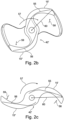
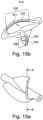
Es ergibt sich unter anderem dadurch ein Rotor für eine komprimierbare Fluidpumpe, insbesondere eine durch ein Blutgefäß in einen Patientenkörper einführbare Blutpumpe, der ein oder mehrere Förderelemente aufweist und radial zwischen einem ersten, komprimierten und einem zweiten, radial expandierten Zustand komprimierbar und expandierbar ist und der wenigstens teilweise aus einem durch strangförmige Verstärkungselemente, insbesondere Fasern verstärkten Kunststoff besteht und zur Rotation um eine Rotationsachse vorgesehen ist, wobei der Rotor im ersten, komprimierten Zustand gespannt und im zweiten, expandierten Zustand frei von äußeren Spannungen ist und wobei ein dritter Zustand existiert, den der Rotor im Betriebszustand unter Last einnimmt, dadurch gekennzeichnet, dass die Fasern in dem Rotor im dritten Zustand wenigstens abschnittsweise gestreckt verlaufen.Among other things, this results in a rotor for a compressible fluid pump, in particular a blood pump that can be inserted through a blood vessel into a patient's body, which has one or more conveying elements and can be radially compressed and expanded between a first, compressed and a second, radially expanded state and the consists at least partially of a plastic reinforced by strand-like reinforcement elements, in particular fibers, and is provided for rotation about an axis of rotation, the rotor being tensioned in the first, compressed state and free of external tensions in the second, expanded state, and with a third state existing, the the rotor occupies the operating state under load, characterized in that the fibers in the rotor in the third state are stretched at least in sections.
Zu einer besonders guten Stabilisierung des Rotors insgesamt ist vorgesehen, dass Verstärkungselemente/Fasern vorgesehen sind, die sich in radialer Richtung über die Rotationsachse hinaus erstrecken. Damit werden einzelne Förderelemente nicht nur gegen eine Biegung in sich stabilisiert, sondern auch gegenüber einer Schwenkbewegung um einen rotationsachsennahen Teil des Rotors, beispielsweise eine Nabe.For a particularly good stabilization of the rotor as a whole, it is provided that reinforcement elements/fibers are provided which extend beyond the axis of rotation in the radial direction. In this way, individual conveying elements are not only stabilized against bending in themselves, but also against a pivoting movement about a part of the rotor close to the axis of rotation, for example a hub.
Derartige Fluidpumpen werden üblicherweise im komprimierten Zustand durch eine Schleuse in ein Blutgefäß, beispielsweise eine Arterie, eingeführt und bis in die Nähe des Herzens oder teilweise bis in ein Patientenherz hinein eingeschoben, um dort expandiert zu werden. Die Erfindung beschränkt sich jedoch nicht auf derartige Blutpumpen, sondern umfasst auch andere Arten von Blutpumpen mit komprimierbaren und expandierbaren Rotoren oder andere Fluidpumpen, die für medizinische oder nichtmedizinische Zwecke in Systeme von Hohlräumen einführbar sind. Im komprimierten Zustand steht der Rotor einer solchen Pumpe üblicherweise unter einer radialen Kompressionsspannung, indem er beispielsweise durch eine äußere Hülle zusammengehalten wird. Die äußere Hülle kann beispielsweise ein Katheter sein, aus dem die Pumpe zur Expansion hinausgeschoben wird. Der Rotor der Pumpe kann jedoch auch durch jede andere Art äußerer Hülle im komprimierten Zustand zusammengehalten werden.Fluid pumps of this type are usually introduced in the compressed state through a lock into a blood vessel, for example an artery, and pushed into the vicinity of the heart or partially into a patient's heart in order to be expanded there. However, the invention is not limited to such blood pumps, but also includes other types of blood pumps with compressible and expandable rotors or other fluid pumps that can be introduced into cavity systems for medical or non-medical purposes. In the compressed state, the rotor of such a pump is usually under radial compressive stress, for example by being held together by an outer shell. The outer sheath can be, for example, a catheter from which the pump is pushed out for expansion. However, the rotor of the pump can also be held together in the compressed state by any other type of outer casing.
Wird die komprimierende Kraft eliminiert, so entspannt sich die Pumpe, oder zumindest der Rotor der Pumpe, und geht in einen zweiten, expandierten entspannten Zustand über, in dem die radiale Ausdehnung des Rotors sich gegenüber dem ersten, komprimierten Zustand erheblich erweitert.When the compressing force is eliminated, the pump, or at least the rotor of the pump, relaxes and transitions to a second, expanded, relaxed state in which the radial expansion of the rotor increases significantly from the first, compressed state.
Wird dann die Pumpe in Betrieb genommen, indem der Rotor rotatorisch angetrieben und ein Fluid gefördert wird, so geht der Rotor in einen Betriebszustand über, der einem Lastzustand unter der Last der geförderten Flüssigkeit entspricht. Besonders dieser Betriebszustand soll bei einer definierten geometrischen Gestalt des Rotors stattfinden, die von der Höhe der Last möglichst unabhängig sein soll. Der Rotor soll zudem beim Übergang zwischen dem zweiten und dem dritten Zustand eine möglichst geringe Formänderung durchlaufen. Jedoch kann der Rotor im dritten Zustand unter der Last der geförderten Flüssigkeit derart verformt werden, dass der Durchmesser des Rotors sich gegenüber dem zweiten, expandierten Zustand vergrößert.If the pump is then put into operation by the rotor being driven in rotation and a fluid being pumped, the rotor goes into an operating state which corresponds to a load state under the load of the pumped liquid. This operating state in particular should take place with a defined geometric shape of the rotor, which should be as independent as possible of the level of the load. In addition, the rotor should undergo as little change in shape as possible during the transition between the second and third states. However, in the third state, the rotor can be deformed under the load of the pumped liquid in such a way that the diameter of the rotor increases compared to the second, expanded state.
Die strangförmigen Verstärkungselemente/Fasern, die das Kunststoffmaterial des Rotors verstärken, sollen derart in der Matrix des Kunststoffmaterials angeordnet sein, dass sie im dritten Zustand wenigstens abschnittsweise gestreckt verlaufen und dadurch den Rotor in seiner Form gegenüber der Last stabilisieren. Die Fasern sollen dabei in Längsrichtung zugbeansprucht werden. Da die Fasern in Längsrichtung praktisch nicht dehnbar sind, führen entsprechende Belastungen in Längsrichtung der Fasern kaum zu einer merklichen Formveränderung der Matrix. Der Rotor oder einzelne Elemente des Rotors, beispielsweise die Förderelemente, kann/können sich somit in der Form vom komprimierten Zustand bis zum Betriebszustand problemlos so lange verändern, bis die Fasern wenigstens abschnittsweise gestreckt sind. An diesem Punkt wird durch die Verankerung der Fasern im Kunststoffmaterial des Rotors zumindest in dem Bereich, in dem die Fasern gestreckt sind, eine Bewegung in Längsrichtung der Fasern auch unter Last praktisch unmöglich gemacht.The strand-like reinforcement elements/fibers that reinforce the plastic material of the rotor should be arranged in the matrix of the plastic material in such a way that in the third state they are stretched at least in sections and thereby stabilize the shape of the rotor with respect to the load. The fibers should be subjected to tensile stress in the longitudinal direction. Since the fibers are practically inextensible in the longitudinal direction, corresponding loads in the longitudinal direction of the fibers hardly lead to a noticeable change in shape of the matrix. The rotor or individual elements of the rotor, for example the conveying elements, can thus easily change in shape from the compressed state to the operating state until the fibers are stretched at least in sections. At this point, the anchoring of the fibers in the plastic material of the rotor, at least in the area where the fibers are stretched, makes a longitudinal movement of the fibers practically impossible, even under load.
Eine besondere Ausgestaltung der Lösung sieht beispielsweise dabei vor, dass die Verstärkungselemente/Fasern im dritten Zustand (Betriebszustand) des Rotors wenigstens abschnittsweise in Bereichen des Rotors, in denen dieser eine Dehnspannung aufweist, gestreckt und im Wesentlichen in Richtung der Dehnspannung verlaufen.A special embodiment of the solution provides, for example, that the reinforcement elements/fibers in the third state (operating state) of the rotor are stretched at least in sections in areas of the rotor in which it has a stretching stress and run essentially in the direction of the stretching stress.
Die Verstärkungselemente/Fasern sollten wenigstens abschnittsweise in der Verlaufsrichtung angeordnet werden, in der Dehnspannungen im Rotor auftreten, so dass diese Dehnspannungen durch Aufnahme der Längskräfte in den Fasern abgefangen werden und der Rotor sich in seiner Form praktisch nicht bzw. nicht weiter verändert.The reinforcement elements/fibers should be arranged at least in sections in the direction in which the stretching stresses in the rotor are removed occur, so that these expansion stresses are absorbed by absorbing the longitudinal forces in the fibers and the shape of the rotor practically does not change or does not change any further.
Dies erfordert beispielsweise, dass wenigstens ein Teil der Verstärkungselemente/Fasern außerhalb der sogenannten neutralen Faser in den Förderelementen des Rotors verläuft. Im Bereich der sogenannten neutralen Faser und/oder neutralen Fläche in der Nomenklatur der Biegemechanik würde eine zugfeste Faser keine zusätzliche Stabilisierung des Rotors erbringen. Die biegetechnisch neutrale Faser ist bei den hier beschriebenen Rotoren in der Regel eine Fläche, weshalb im Folgenden zur besseren Klarheit der Begriff biegeneutrale Fläche bzw. neutrale Fläche verwendet wird.This requires, for example, that at least part of the reinforcement elements/fibers run outside the so-called neutral fiber in the conveying elements of the rotor. In the area of the so-called neutral fiber and/or neutral surface in the nomenclature of bending mechanics, a tensile fiber would not provide any additional stabilization of the rotor. In the rotors described here, the bending-neutral axis is usually a surface, which is why the term bending-neutral surface or neutral surface is used below for better clarity.
Es kann deshalb vorgesehen sein, dass mehr als die Hälfte der Verstärkungselemente/Fasern in Bereichen des Rotors und/oder der Förderelemente angeordnet sind, in denen dieser/diese im Betriebszustand Dehnspannungen aufweist/aufweisen. Besonders vorteilhaft ist es dabei, wenn viele Fasern in dem Bereich des Rotors oder eines Förderelements angeordnet sind, der unter Last Dehnspannungen aufweist.Provision can therefore be made for more than half of the reinforcement elements/fibers to be arranged in areas of the rotor and/or the conveying elements in which the latter has/have expansion stresses in the operating state. It is particularly advantageous if many fibers are arranged in the area of the rotor or a conveying element that exhibits expansion stresses under load.
Zudem kann vorgesehen sein, dass bei dem Rotor zwischen dem zweiten, expandierten Zustand in dem dritten Betriebszustand bezüglich der äußeren Form im Wesentlichen keine Unterschiede bestehen.In addition, it can be provided that there are essentially no differences in the outer shape of the rotor between the second, expanded state and the third operating state.
Zudem kann vorteilhaft vorgesehen sein, dass im Betriebszustand wenigstens ein Teil der Fasern, insbesondere die Mehrheit der Verstärkungselemente/Fasern, abschnittsweise gerade verlaufen. Zwischen den Abschnitten, in denen die Verstärkungselemente/Fasern gerade verlaufen, können andere gerade Abschnitte oder auch gekrümmte Abschnitte der Fasern vorgesehen sein.In addition, it can advantageously be provided that in the operating state at least some of the fibers, in particular the majority of the reinforcement elements/fibers, run straight in sections. Between the sections in which the reinforcing elements / fibers run straight, others straight sections or curved sections of the fibers can be provided.
Es kann auch vorgesehen sein, dass im Betriebszustand wenigstens ein Teil der Fasern, insbesondere die Mehrheit der Verstärkungselemente/Fasern, entlang der Längsrichtung des jeweiligen Förderelementes mit einer geringeren Krümmung verlaufen als die neutrale Fläche des jeweiligen Förderelementes im Sinne der Festigkeitslehre. Durch diese Anordnung der Verstärkungselemente/Fasern wird sichergestellt, dass die Verstärkungsfasern einerseits im Betriebszustand bereits stark gestreckt sind und dass sie andererseits außerhalb der neutralen Fläche der Förderelemente verlaufen und somit in solchen Bereichen, die unter Belastungen Dehnspannungen aufweisen können.It can also be provided that in the operating state at least some of the fibers, in particular the majority of the reinforcement elements/fibers, run along the longitudinal direction of the respective conveyor element with a smaller curvature than the neutral surface of the respective conveyor element in terms of strength theory. This arrangement of the reinforcement elements/fibers ensures that the reinforcement fibers are, on the one hand, already severely stretched during operation and, on the other hand, that they run outside the neutral surface of the conveying elements and thus in areas that can exhibit stretching stresses under loads.
Es kann zudem auch vorgesehen sein, dass der Kunststoff des Rotors eine Shore-Härte <100 D, insbesondere < 80 D, aufweist. Durch die geringe Shore-Härte, die beispielsweise auch kleiner als 80 D gewählt werden kann, ergibt sich bei starker Biegung oder Knickung des Materials für die eingebetteten Verstärkungselemente/Fasern die Möglichkeit, in das nachgiebige Material der Basis auszuweichen und dadurch den Krümmungsradius nach unten zu begrenzen. Damit ergibt sich eine Verringerung der Bruchgefahr für die Elemente/Fasern.In addition, it can also be provided that the plastic of the rotor has a Shore hardness of <100 D, in particular <80 D. Due to the low Shore hardness, which can also be chosen to be less than 80 D, for example, if the material bends or buckles severely, the embedded reinforcement elements/fibers have the option of evading into the flexible material of the base and thereby increasing the radius of curvature downwards limit. This results in a reduction in the risk of breakage for the elements/fibers.
Zudem kann bei einem solchen Rotor auch vorgesehen sein, dass ein erster Anteil von mehr als 30%, insbesondere mehr als 50%, der Verstärkungselemente/Fasern im expandierten Zustand des Rotors im Wesentlichen gestreckt von einem der Rotorachse am nächsten liegenden Abschnitt zu einem der Rotationsachse ferner liegenden zweiten Abschnitt verläuft. Durch diese Positionierung, Ausrichtung und Formung der Verstärkungselemente/Fasern wird eine Überstreckung des Rotors über den expandierten Zustand hinaus wirkungsvoll vermieden.In addition, with such a rotor it can also be provided that a first proportion of more than 30%, in particular more than 50%, of the reinforcing elements/fibers in the expanded state of the rotor are essentially stretched from a section closest to the rotor axis to one of the axis of rotation further lying second section runs. This positioning, alignment and shaping of the reinforcement elements/fibers effectively prevents the rotor from being overstretched beyond the expanded state.
Eine Rotorkonstruktion kann auch dadurch ausgestaltet werden, dass ein erster Anteil der Verstärkungselemente/Fasern, der mehr als 30% der Verstärkungselemente/Fasern, insbesondere mehr als 50%, der Verstärkungselemente/Fasern beträgt, eine Länge aufweist, die mindestens 30%, insbesondere mindestens 50%, der Maximalhöhe der Förderelemente, gemessen in Radialrichtung des Rotors im expandierten Zustand, entspricht. Hierdurch ergeben sich Stabilisierungskräfte, die größere Teile des Rotors umfassen und diesen insgesamt stabilisieren.A rotor construction can also be designed in that a first portion of the reinforcement elements/fibers, which is more than 30% of the reinforcement elements/fibers, in particular more than 50%, of the reinforcement elements/fibers, has a length that is at least 30%, in particular at least 50% of the maximum height of the conveying elements, measured in the radial direction of the rotor in the expanded state. This results in stabilization forces that encompass larger parts of the rotor and stabilize it as a whole.
Dazu kann außerdem vorgesehen sein, dass der erste Anteil der Verstärkungselemente/Fasern im Betriebszustand im Wesentlichen senkrecht zur Rotationsachse verläuft. Durch diese Ausrichtung der Verstärkungselemente/Fasern können Dehnspannungen im Rotor, die durch die Last des zu fördernden Fluids erzeugt werden, optimal aufgenommen werden.For this purpose, it can also be provided that the first portion of the reinforcement elements/fibers runs essentially perpendicularly to the axis of rotation in the operating state. This orientation of the reinforcement elements/fibers means that expansion stresses in the rotor, which are generated by the load of the fluid to be pumped, can be optimally absorbed.
Weiter kann die Bauart des Rotors dadurch ausgestaltet werden, dass der Durchmesser der Verstärkungselemente/Fasern, insbesondere des ersten Anteils der Verstärkungselemente/Fasern, kleiner als 40 Mikrometer ist. Durch einen derart klein gestalteten Durchmesser der Verstärkungselemente/Fasern können geringe Biegeradien erreicht werden, so dass die Bruchgefahr für die Verstärkungselemente/Fasern weiter vermindert ist.Furthermore, the design of the rotor can be designed in that the diameter of the reinforcement elements/fibers, in particular of the first portion of the reinforcement elements/fibers, is less than 40 micrometers. With such a small diameter of the reinforcement elements/fibers, small bending radii can be achieved, so that the risk of breakage for the reinforcement elements/fibers is further reduced.
Zudem kann vorgesehen sein, dass die Oberfläche der Verstärkungselemente/Fasern mit einem Haftvermittler versehen ist. Dadurch wird eine gute Verankerung der Verstärkungselemente/Fasern im Kunststoffmaterial der Matrix erreicht, was zu einer weiteren Verbesserung bei der Aufnahme von Dehnspannungen durch die Verstärkungselemente/Fasern führt.In addition, it can be provided that the surface of the reinforcing elements/fibers is provided with an adhesion promoter. This achieves good anchoring of the reinforcement elements/fibers in the plastic material of the matrix, which leads to a further improvement in the absorption of expansion stresses by the reinforcement elements/fibers.
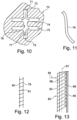
Die Offenbarung bezieht sich zudem auf ein Verfahren zur Herstellung (nicht unter den Schutzumfang des Anspruchs fallend) eines Rotors nach Anspruch 1 oder einem der folgenden mittels eines Gießverfahrens (nicht unter den Schutzumfang des Anspruchs fallend), insbesondere eines Spritzgießverfahrens, bei dem das Material der Förderelemente in Radialrichtung in Bezug auf die Rotorachse in die Volumina der Förderelemente derart eingebracht wird, dass der Gießwerkstoff in das Volumen jedes einzelnen Förderelementes jeweils in Radialrichtung einströmt.The disclosure also relates to a method of manufacturing (not falling within the scope of the claim) a rotor according to claim 1 or one of the following by means of a casting process (not falling within the scope of the claim), in particular an injection molding process, in which the material of the Conveying elements is introduced in the radial direction with respect to the rotor axis in the volumes of the conveying elements in such a way that the casting material flows into the volume of each individual conveying element in the radial direction.
Bei einem solchen Verfahren kann das Gussmaterial beispielsweise in Axialrichtung im zentralen Bereich des Rotors, beispielsweise im Volumen einer Rotornabe, eingespritzt und von dort radial in die einzelnen Förderelemente hinein verteilt werden. Jedes einzelne Förderelement wird dann in einer radial gerichteten Flussrichtung des Materials von innen nach außen gefüllt. Es ist jedoch auch eine Füllung von den radial außen liegenden Enden der Förderelemente radial nach innen, auf die Rotorachse hin gerichtet, möglich.In such a method, the casting material can be injected, for example, in the axial direction in the central region of the rotor, for example in the volume of a rotor hub, and from there distributed radially into the individual conveying elements. Each individual conveyor element is then in a radial Direction of flow of the material filled from the inside to the outside. However, filling from the radially outer ends of the conveying elements radially inwards, directed towards the rotor axis, is also possible.
Die in dem Gussmaterial vorhandenen Verstärkungselemente/Fasern oder auch Folienabschnitte, die beispielsweise aus Glas, jedoch auch aus Kohlenstoff bzw. Polycarbonat oder Metall bestehen können, werden durch den Strom des Matrixmaterials mitgenommen und vorwiegend in Flussrichtung des Materials ausgerichtet.The reinforcing elements/fibers or foil sections present in the cast material, which can consist of glass, for example, but also of carbon or polycarbonate or metal, are carried along by the flow of the matrix material and are primarily aligned in the flow direction of the material.
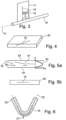
Eine für die Herstellung des beschriebenen Rotors und für das beschriebene Verfahren optimierte Gießform soll ebenfalls vorgestellt werden. Diese zeichnet sich dadurch aus, dass bei den Volumina der Förderelemente an deren radial verlaufenden Kanten Überströmkanäle vorgesehen sind, um einen störungsfreien Fluss des Gießwerkstoffs in Radialrichtung zu ermöglichen.A casting mold optimized for the production of the described rotor and for the described method is also to be presented. This is characterized in that overflow channels are provided in the volumes of the conveying elements on their radially running edges in order to enable a trouble-free flow of the casting material in the radial direction.
Durch die an den Kanten vorgesehenen Überströmkanäle wird die Ausbildung von Verwirbelungen mit lokalen Rückströmungen im Bereich der Kanten der Förderelemente verhindert, so dass eine weitgehend laminare Strömung ausgebildet werden kann. Hierdurch werden die Verstärkungselemente/Fasern in überwiegend gestreckter Lage in die Matrix eingebettet. Dies ist insbesondere deshalb sinnvoll, da die Gießform den Guss eines Rotors im zweiten, expandierten Zustand, d. h. frei von äußeren Spannungen, ermöglicht.The overflow channels provided at the edges prevent the formation of turbulence with local backflows in the area of the edges of the conveying elements, so that a largely laminar flow can be formed. As a result, the reinforcing elements/fibers are embedded in the matrix in a predominantly stretched position. This makes sense in particular because the casting mold allows the casting of a rotor in the second, expanded state, i. H. free from external stresses.
Zusätzlich zu den an den seitlichen Kanten der Förderelemente vorgesehenen Überströmkanälen können auch an den radial außen gelegenen Enden der Volumina in der Gießform Überströmkanäle ausgebildet sein, die das Abströmen an den radial außen gelegenen Enden der Förderelemente erlauben. Das überschüssige Gussmaterial kann nach wenigstens teilweisem Erstarren des Rotors in der Gießform entfernt werden.In addition to the overflow channels provided on the lateral edges of the conveying elements, overflow channels can also be formed at the radially outer ends of the volumes in the casting mold, which allow outflow at the radially outer ends of the conveying elements. The excess casting material can be removed after the rotor has at least partially solidified in the casting mold.
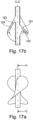
Es kann bei der Anordnung der Verstärkungselemente/Fasern im Volumen der Förderelemente gezielt eine Beabstandung von der biegeneutralen Fläche angestrebt werden, um bei der Belastung durch den Fluidgegendruck im Betriebszustand eine besondere Stabilisierung bei Ausbiegung der Förderelemente in eine Richtung durch Streckung der Verstärkungselemente/Fasern zu erreichen. Jedenfalls sollten die Verstärkungselemente/Fasern vorteilhaft im Inneren der Förderelemente verlaufen und einen bestimmten Mindestabstand zu den äußeren Begrenzungsflächen der Förderelemente einhalten.When arranging the reinforcing elements/fibers in the volume of the conveying elements, a distance from the bending-neutral surface can be specifically aimed at in order to Operating condition to achieve a special stabilization in deflection of the conveying elements in one direction by stretching the reinforcing elements / fibers. In any case, the reinforcing elements/fibers should advantageously run inside the conveying elements and maintain a certain minimum distance from the outer boundary surfaces of the conveying elements.
Es können in dem Rotor auch mehrere Gruppen von Verstärkungselementen/Fasern unterschiedlicher Länge vorgesehen sein, wobei wenigstens eine Gruppe eine bestimmte Mindestlänge aufweist, während die Verstärkungselemente/Fasern von einer oder mehreren Gruppen kürzer sind oder eine Längenverteilung aufweisen, die nur vernachlässigbar wenige Verstärkungselemente/Fasern oberhalb einer Faserlänge aufweist, die unterhalb einer typischen Länge des ersten Anteils der Verstärkungselemente/Fasern liegt. Typisch liegt die Durchschnittslänge der kürzeren Verstärkungselemente/Fasern bei weniger als einem Drittel der Länge des ersten Anteils der Verstärkungselemente/Fasern,Several groups of reinforcement elements/fibers of different lengths can also be provided in the rotor, with at least one group having a certain minimum length, while the reinforcement elements/fibers of one or more groups are shorter or have a length distribution that only negligibly few reinforcement elements/fibers above a fiber length that is below a typical length of the first portion of the reinforcing members/fibers. Typically, the average length of the shorter reinforcement members/fibers is less than one-third the length of the first portion of reinforcement members/fibers,
Der Rotor kann vorteilhaft dadurch ausgestaltet werden, dass jedes Verstärkungselement / jede Faser des ersten Anteils der Verstärkungselemente/Fasern in ihrem Verlauf höchstens 45° in Axialrichtung und/oder Azimutalrichtung von einer radial auf die Rotorachse (14) ausgerichteten Lage abweicht. Die Verstärkungselemente/Fasern verlaufen dann in einer Fläche, in der auch die gesamte Rotationsachse des Rotors verläuft, so dass sie sich beispielsweise direkt von der Rotationsachse ausgehend zunächst senkrecht radial nach außen erstrecken können. Jedoch ist auch eine Ausrichtung der Verstärkungselemente/Fasern von der Rotationsachse radial in einem Winkel zwischen 45° und 90° zur Rotationsachse möglich. In einer Ausgestaltung weist die Erstreckung der Verstärkungselemente/Fasern jedenfalls keine oder nur geringe azimutale (in Umfangsrichtung verlaufende) Ausrichtung auf.The rotor can advantageously be designed in such a way that each reinforcement element/each fiber of the first portion of the reinforcement elements/fibers deviates at most 45° in the axial direction and/or azimuthal direction from a position aligned radially with the rotor axis (14). The reinforcement elements/fibers then run in a surface in which the entire axis of rotation of the rotor also runs, so that they can, for example, initially extend vertically radially outwards directly starting from the axis of rotation. However, it is also possible to align the reinforcement elements/fibers radially from the axis of rotation at an angle of between 45° and 90° to the axis of rotation. In one embodiment, the extent of the reinforcement elements/fibers has no or only a slight azimuthal alignment (running in the circumferential direction).
Der Gegenstand kann weiterhin dadurch ausgestaltet sein, dass die Förderelemente aus einem Schaumstoff bestehen. Dabei ist insbesondere an einen geschlossenporigen Schaumstoff gedacht, der durch die Verstärkungsfasern effektiv stabilisierbar ist und der dennoch einfach und in ausreichendem Maß komprimierbar ist. Bei der Kompressionsbewegung ist gerade bei einem Schaumstoff ein Ausweichen der Verstärkungselemente/Fasern zur Verhinderung der Unterschreitung eines kritischen Biegeradius besonders einfach möglich. Üblicherweise weisen derartige Schaumstoffe im Inneren des Volumens der Förderelemente entsprechende Poren auf, sind jedoch an den äußeren Begrenzungsflächen praktisch vollständig geschlossen.The object can also be designed in that the conveying elements consist of a foam. In particular, a closed-cell foam is intended that can be effectively stabilized by the reinforcing fibers and that can nevertheless be compressed easily and to a sufficient extent. During the compression movement, especially with a foam, the reinforcing elements/fibers are prevented from yielding falling below a critical bending radius is particularly easy. Such foams usually have corresponding pores inside the volume of the conveying elements, but are practically completely closed at the outer boundary surfaces.
Der Rotor kann auch derart gestaltet sein, dass ein Anteil von Verstärkungselementen/Fasern im expandierten Zustand des Rotors zu den Verstärkungselementen/Fasern des ersten Teils quer verläuft und insbesondere mit diesen im Mittel Winkel von mindestens 30° einschließt. Dadurch kann die jeweilige Gruppe von Fasern ein Biegen des Rotors oder eines Förderelements des Rotors jeweils in Längsrichtung der Fasern fast vollständig verhindern, sofern die Biegung in einer Richtung erfolgt, in der die Fasern auf Zug beansprucht werden. Sind in der beschriebenen Art zwei Richtungen durch die verschiedene Anordnung von zwei Fasergruppen ausgezeichnet, so lässt sich eine dreidimensionale Form des Rotors oder eines Teils des Rotors in sehr effizienter Weise stabilisieren und gegen Biegung in verschiedenen Richtungen verfestigen.The rotor can also be designed in such a way that a proportion of reinforcement elements/fibers in the expanded state of the rotor runs transversely to the reinforcement elements/fibers of the first part and in particular encloses a central angle of at least 30° with them. As a result, the respective group of fibers can almost completely prevent the rotor or a conveying element of the rotor from bending in the longitudinal direction of the fibers, provided that the bending occurs in a direction in which the fibers are subjected to tensile stress. If, in the manner described, two directions are distinguished by the different arrangement of two fiber groups, a three-dimensional shape of the rotor or a part of the rotor can be stabilized in a very efficient manner and strengthened against bending in different directions.
Es kann zudem vorgesehen sein, dass die Verstärkungselemente/Fasern wenigstens teilweise in Form von Gewebeabschnitten mit längs und quer verlaufenden Fasern vorliegen. Die Gewebeabschnitte können sich beispielsweise in ihrer Längsrichtung wenigstens zwei-, drei-, fünf- oder zehnmal so weit erstrecken wie in der senkrecht dazu liegenden Querrichtung, so dass sie jeweils einen länglichen Streifen bilden. Innerhalb dieser Gewebe sind dann ohne weiteres erste Fasern in einer Längsrichtung und dazu quer verlaufende zweite Fasern senkrecht oder in einem stumpfen Winkel dazu vorgesehen.Provision can also be made for the reinforcement elements/fibers to be present at least partially in the form of fabric sections with longitudinal and transverse fibers. The fabric sections can, for example, extend in their longitudinal direction at least two, three, five or ten times as far as in the transverse direction perpendicular thereto, so that they each form an elongate strip. Within these fabrics, first fibers are then readily provided in a longitudinal direction and second fibers running transversely thereto are perpendicular or at an obtuse angle thereto.
Es kann beispielsweise auch vorgesehen sein, dass die Verstärkungselemente in Form von Folienstreifen vorliegen, deren Länge wenigstens dreimal, insbesondere wenigstens fünfmal, weiter insbesondere wenigstens zehnmal so groß ist wie ihre Breite. Diese Folienstreifen können aus einem anisotropen Polymer bestehen, das beispielsweise in Längsrichtung wesentlich zugfester ist als in Querrichtung. Sie können jedoch auch aus einer isotropen Folie bestehen, beispielsweise aus zugfestem Kunststoffmaterial oder auch aus einem Metall, wie Aluminium, Silber, Titan, Nitinol oder Gold.Provision can also be made, for example, for the reinforcing elements to be in the form of foil strips whose length is at least three times, in particular at least five times, more particularly at least ten times as great as their width. These foil strips can consist of an anisotropic polymer which, for example, has significantly greater tensile strength in the longitudinal direction than in the transverse direction. However, they can also consist of an isotropic foil, for example of a plastic material with high tensile strength or of a metal such as aluminum, silver, titanium, nitinol or gold.
Vorteilhaft kann zudem vorgesehen sein, dass die Verstärkungselemente von dem Kunststoff, aus dem der Rotor überwiegend besteht, wenigstens auf einem Anteil von 90%, insbesondere 99 %, ihrer Oberfläche, weiter insbesondere vollständig, umschlossen sind. Es kann im Einzelfall geschehen, dass Verstärkungselemente in der Spritzgießform an deren Wand stoßen, so dass sie im fertigen Produkt an die äußere Oberfläche des Rotors treten. Dabei sind dann jedoch im Normalfall nur die Enden der Verstärkungselemente an der Außenseite des Rotors freiliegend angeordnet, wobei auch dies durch das Einbringen von Verstärkungselementen und eine geeignete Strömungsführung beim Spritzgießen während des Spritzgießvorgangs relativ unwahrscheinlich wird.Advantageously, it can also be provided that the reinforcing elements are surrounded, more particularly completely, by the plastic of which the rotor is predominantly made, at least over a proportion of 90%, in particular 99%, of their surface. In individual cases it can happen that reinforcement elements in the injection mold hit the wall, so that in the finished product they come to the outer surface of the rotor. In this case, however, only the ends of the reinforcing elements are then normally arranged exposed on the outside of the rotor, with this also becoming relatively unlikely due to the introduction of reinforcing elements and a suitable flow guide during the injection molding process.
Es kann bei dem Rotor außerdem auch vorgesehen sein, dass das Kunststoffmaterial, das die Verstärkungselemente einbettet, auf der im Betrieb von dem Fluidgegendruck nicht belasteten Seite der Förderelemente wenigstens bereichsweise andere Eigenschaften aufweist als auf der mit dem Fluidgegendruck belasteten Seite der Förderelemente, insbesondere auf der von dem Fluidgegendruck nicht belasteten Seite stärker vernetzt oder geschrumpft ist oder dort auf der Oberfläche eine auf dem Förderelement geschrumpfte Auflage in Form von einer oder mehreren Folien, Beschichtungen oder Fasern trägt. Mit den beiden Seiten der Förderelemente sind in diesem Zusammenhang die Volumenbereiche auf den beiden Seiten der im Pumpbetrieb bei der Biegebelastung biegeneutralen Ebene oder Fläche im Volumen des jeweiligen Förderelementes gemeint.In the case of the rotor, it can also be provided that the plastic material that embeds the reinforcement elements has, at least in some areas, different properties on the side of the conveying elements that is not loaded by the fluid counter-pressure during operation than on the side of the conveying elements that is loaded with the fluid counter-pressure, in particular on the is more strongly crosslinked or shrunken from the side not subjected to the fluid counter-pressure or carries on the surface a covering in the form of one or more foils, coatings or fibers which has been shrunken onto the conveying element. In this context, the two sides of the conveying elements mean the volume areas on the two sides of the plane or surface in the volume of the respective conveying element that is neutral in terms of bending during pump operation under the bending load.
Eines der Ziele, die mit der Erfindung angestrebt werden können, ist, dass der zweite Zustand des Rotors, den dieser im von außen kraftfreien Zustand einnimmt, sich möglichst wenig von einem dritten Zustand unterscheidet, den der Rotor im Betrieb während seiner Rotation in einem Fluid unter der Wirkung des Fluidgegendrucks einnimmt. Deshalb ist es wünschenswert, dass die Verstärkungsfasern bereits im zweiten Zustand des Rotors möglichst weitgehend gestreckt sind und in einer Richtung verlaufen, in der sie zumindest Biegungen des Rotors begrenzen.One of the goals that can be aimed at with the invention is that the second state of the rotor, which it assumes when there is no external force, differs as little as possible from a third state, which the rotor is in operation during its rotation in a fluid under the action of the fluid back pressure. It is therefore desirable for the reinforcing fibers to be as stretched as possible already in the second state of the rotor and to run in a direction in which they at least limit flexing of the rotor.
Dies kann dadurch unterstützt werden, dass die Form des Rotors in dem zweiten Zustand, in dem er sich kraftfrei befindet, sich von der Form, die der Rotor in der Spritzgießform einnimmt, unterscheidet. Es kann durch geeignete Gestaltung der Kunststoffmatrix, die durch den Spritzgießwerkstoff gebildet wird, bewirkt werden, dass bereits im von außen kräftefreien Zustand durch elastische Kräfte des Spritzgießwerkstoffs eine Verformung in Richtung auf den dritten Zustand hin stattfindet, die die Fasern vorspannt. Dieser Effekt kann beispielsweise dadurch erreicht werden, dass ein von den Verstärkungselementen unterschiedliches Material im oder am Rotor vorgesehen ist, dass den Rotor, insbesondere die Förderelemente, in eine Form bringt, in der die Verstärkungselemente vorgespannt sind. Da beim eigentlichen Vergießen der Verstärkungselemente in der Matrix diese mehr oder weniger kraftfrei vorliegen, gelingt dies durch eine Veränderung der Kunststoffmatrix oder des Körpers des Rotors insgesamt nach dem Abschluss des Spritzgießvorgangs. Beispielsweise kann die Kunststoffmatrix nach der Entnahme aus der Spritzgussform besonders behandelt werden, derart, dass das Material der Förderelemente auf der Seite, die dem Fluidgegendruck während des Betriebs ausgesetzt ist, gelängt oder auf der gegenüberliegenden Seite geschrumpft bzw. anisotrop verkürzt wird. Dies kann beispielsweise durch eine ungleichmäßige Vernetzung der Kunststoffmatrix geschehen, die auf den beiden Seiten der neutralen Faser der Förderelemente unterschiedlich ist. Es kann jedoch auch dadurch gelingen, dass die Förderelemente auf der Seite, die der im Betrieb dem Fluidgegendruck ausgesetzten Seite der Förderelemente gegenüberliegt, mit einer Folie beschichtet werden, die nach der Beschichtung schrumpft oder geschrumpft werden kann, beispielsweise durch Elektronenstrahlvernetzung oder UV-Vernetzung oder durch thermische Behandlung.This can be supported by the fact that the shape of the rotor in the second state, in which it is free of force, is different from the shape of the Rotor occupies in the injection mold differs. A suitable design of the plastic matrix formed by the injection molding material can cause deformation towards the third state, which prestresses the fibers, even in the externally force-free state due to elastic forces of the injection molding material. This effect can be achieved, for example, by providing a material that is different from the reinforcement elements in or on the rotor, that brings the rotor, in particular the conveying elements, into a shape in which the reinforcement elements are prestressed. Since the reinforcing elements are present in the matrix more or less free of force when they are actually cast, this is achieved by changing the plastic matrix or the body of the rotor as a whole after the injection molding process is complete. For example, the plastic matrix can be specially treated after removal from the injection mold such that the material of the conveying elements is lengthened on the side that is exposed to the fluid counterpressure during operation or shrunk or anisotropically shortened on the opposite side. This can happen, for example, as a result of uneven cross-linking of the plastic matrix, which is different on the two sides of the neutral fiber of the conveying elements. However, it can also be successful if the conveyor elements are coated with a film on the side opposite the side of the conveyor elements that is exposed to the fluid counterpressure during operation, which shrinks or can be shrunk after the coating, for example by electron beam crosslinking or UV crosslinking or by thermal treatment.
Es kann auch ein Rotor für eine komprimierbare Fluidpumpe vorliegen, der radial zwischen einem ersten, komprimierten und einem zweiten, expandierten Zustand expandierbar und komprimierbar ist, wobei zudem vorgesehen sein kann, dass ein oder mehrere Förderelemente des Rotors durch Spritzgießen mit gleichzeitigem Hinzufügen von Verstärkungselementen im expandierten Zustand hergestellt ist, wobei die Verstärkungselemente durch einen Spritzgießwerkstoff allseitig umschlossen sind und wenigstens abschnittsweise im expandierten Zustand gestreckt, insbesondere zu wenigstens 90 %, weiter insbesondere zu 95 %, weiter insbesondere zu 99 % gestreckt bzw. bei Verwendung eines Gewebes soweit wie möglich gestreckt vorliegen.There can also be a rotor for a compressible fluid pump, which can be expanded and compressed radially between a first, compressed and a second, expanded state, it also being possible for one or more conveying elements of the rotor to be formed by injection molding with the simultaneous addition of reinforcing elements in the is produced in an expanded state, the reinforcing elements being surrounded on all sides by an injection molding material and being stretched at least in sections in the expanded state, in particular at least 90%, more particularly 95%, more particularly 99% stretched or, if a fabric is used, stretched as far as possible present.
Der Rotor kann beispielsweise auch derart gestaltet sein, dass die Verstärkungselemente im zweiten, expandierten Zustand des Rotors ohne einen Fluidgegendruck in einem solchen Maß gestreckt vorliegen, dass sie sich beim Übergang zu einem dritten Zustand, der den Betriebszustand mit einem Fluidgegendruck darstellt, um weniger als 5 %, insbesondere weniger als 1 %, verlängern, wobei die Verlängerung insbesondere am Abstand der beiden Enden eines Verstärkungselementes voneinander vor und während der Zugbelastung bemessen ist.The rotor can, for example, also be designed in such a way that the reinforcing elements are stretched to such an extent in the second, expanded state of the rotor without a fluid counter-pressure that they move by less than during the transition to a third state, which represents the operating state with a fluid counter-pressure 5%, in particular less than 1%, lengthen, the lengthening being measured in particular at the distance between the two ends of a reinforcing element from one another before and during the tensile load.
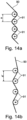
Es kann beispielsweise bei dem Rotor weiter vorgesehen sein, dass in einem zweiten, expandierten Zustand des Rotors und/oder einem dritten Betriebszustand mit Fluidgegendruck wenigstens ein Anteil der Verstärkungselemente, insbesondere mindestens 10%, weiter insbesondere mindestens 30%, in wenigstens einem Bereich eines Förderelementes, in dem dieses gekrümmt ist, gestreckt und gerade verlaufen.In the case of the rotor, for example, it can also be provided that in a second, expanded state of the rotor and/or a third operating state with fluid counter-pressure, at least a proportion of the reinforcing elements, in particular at least 10%, more particularly at least 30%, in at least one region of a conveying element , in which this is curved, stretched and straight.
Es kann außerdem vorgesehen sein, dass in einem Bereich eines Förderelementes, in dem dieses gekrümmt ist, wenigstens zwei Anteile von Verstärkungselementen gerade und gestreckt verlaufen, wobei die Richtungen, in denen die Verstärkungselemente verlaufen, bei dem jeweiligen Anteil parallel, jedoch bei den verschiedenen Anteilen verschieden sind. Die Fasern der verschiedenen Gruppen können dabei bereits miteinander verbunden als Gewebe oder getrennt voneinander, insbesondere nacheinander, in die Spritzgussform eingebracht werden.It can also be provided that in a region of a conveying element in which it is curved, at least two sections of reinforcing elements run straight and stretched, the directions in which the reinforcing elements run being parallel in the respective section but in the different sections are different. The fibers of the different groups can be introduced into the injection mold already connected to one another as a fabric or separately from one another, in particular one after the other.
Eine weitere Ausgestaltung des Rotors kann vorsehen, dass die Länge der Verstärkungselemente bei wenigstens 30 %, insbesondere wenigstens 50 %, der Elemente größer ist als die durchschnittliche Dicke der Förderelemente, insbesondere wenigstens zweimal so lang, weiter insbesondere wenigstens 5-mal oder 10-mal so lang. Die so gekennzeichneten langen Verstärkungselemente können beim Füllen des Gießwerkstoffs durch andere Füllelemente, wie beispielsweise sehr kurze Fasern und/oder Partikel, ergänzt werden, wobei die kurzen Fasern dabei auch jeweils in gestreckter Form vorliegen können. Dies bewirkt jedoch wenig in Bezug auf eine Begrenzung der Krümmung des Rotors, da diese Fasern üblicherweise sehr kurz sind. Mit der Dicke der Förderelemente ist in diesem Zusammenhang an jedem Punkt der Förderelemente die Ausdehnung in derjenigen Richtung gemeint, in der die Ausdehnung des jeweiligen Förderelements am geringsten ist.A further configuration of the rotor can provide that the length of the reinforcing elements is greater than the average thickness of the conveying elements for at least 30%, in particular at least 50% of the elements, in particular at least twice as long, more particularly at least 5 times or 10 times so long The long reinforcing elements identified in this way can be supplemented by other filling elements, such as very short fibers and/or particles, when filling the casting material, with the short fibers also being able to be in a stretched form. However, this does little in terms of limiting the curvature of the rotor as these fibers are usually very short. In this context, the thickness of the conveying elements is at every point of the conveying elements meaning the extension in that direction in which the extension of the respective conveying element is the smallest.
Eine weitere Ausgestaltung des Rotors kann vorsehen, dass Verstärkungselemente, insbesondere Fasern, in den sie einbettenden Kunststoff in einem Spritzgussverfahren eingebracht sind und während der Zeit, in der sich der Rotor in der Spritzgussform befindet, einen abschnittsweise gekrümmten Verlauf entlang der Strömung des Kunststoffs in die Spritzgussform aufweisen.A further configuration of the rotor can provide that reinforcement elements, in particular fibers, are introduced into the plastic embedding them in an injection molding process and, during the time in which the rotor is in the injection mold, have a course that is curved in sections along the flow of the plastic into the Have injection mold.
Die Offenbarung bezieht sich zudem auch auf eine Gießform (nicht unter den Schutzumfang des Anspruchs fallend) für einen Rotor der oben beschriebenen Art, bei der vorgesehen ist, dass bei den Volumina der Förderelemente an deren radial verlaufenden Kanten Überströmkanäle vorgesehen sind, um einen störungsfreien Fluss des Gießwerkstoffs in Radialrichtung zu ermöglichen.The disclosure also relates to a casting mold (not falling under the scope of protection of the claim) for a rotor of the type described above, in which it is provided that overflow channels are provided in the volumes of the conveying elements at their radially running edges in order to ensure a trouble-free flow to allow the casting material in the radial direction.
Ein Verfahren zur Herstellung des oben beschriebenen Rotors kann vorsehen, dass das Material der Förderelemente in Radialrichtung in Bezug auf die Rotorachse in die Volumina der Förderelemente derart eingebracht wird, dass der Gießwerkstoff in das Volumen jedes einzelnen Förderelementes jeweils in Radialrichtung einströmt.A method for producing the rotor described above can provide that the material of the conveying elements is introduced into the volumes of the conveying elements in the radial direction in relation to the rotor axis in such a way that the casting material flows into the volume of each individual conveying element in the radial direction.
Durch Anordnung und Größe der Überströmkanäle der Gießform kann darüber hinaus die Strömungsrichtung des einfließenden Gießwerkstoffes und damit die Ausrichtung der Fasern entlang der Strömung gesteuert werden.In addition, the direction of flow of the inflowing casting material and thus the orientation of the fibers along the flow can be controlled by the arrangement and size of the overflow channels of the casting mold.
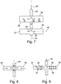
Ein weiteres Verfahren zur Herstellung eines Rotors kann vorsehen, dass der Rotor durch Gießen, insbesondere Spritzgießen, hergestellt wird, wobei das Spritzgießverfahren in zwei aufeinanderfolgenden Phasen mit unterschiedlichen Einspritzrichtungen und/oder von zwei verschiedenen Einspritzstellen aus durchgeführt wird. Hierdurch können gezielt Verstärkungselemente/Fasern in den Spritzgießwerkstoff eingebracht werden, die gruppenweise in unterschiedlichen Richtungen verlaufen.A further method for producing a rotor can provide that the rotor is produced by casting, in particular injection molding, with the injection molding process being carried out in two successive phases with different injection directions and/or from two different injection points. In this way, reinforcement elements/fibers that run in groups in different directions can be introduced into the injection molding material in a targeted manner.
Es kann auch bei einem Verfahren zur Herstellung eines Rotors vorgesehen sein, dass der Rotor nach dem Spritzgießen einer Behandlung unterworfen wird, die eine unterschiedliche Schrumpfung und/oder Vernetzung des Gussmaterials auf der im Betrieb durch den Fluidgegendruck belasteten Seite der Förderelemente als auf der dieser gegenüberliegenden Seite bewirkt. Hierdurch kann der Rotor durch Erzeugung innerer Spannungen derart vorgespannt werden, dass er ohne Einwirkung äußerer Kräfte bereits den dritten Zustand, d. h. einen Betriebszustand, einnimmt, der stabil ist, wenn der Rotor einem Fluidgegendruck ausgesetzt ist. Dies geschieht dadurch, dass die inneren Spannungen derart gerichtet und bemessen sind, dass hierdurch die Verstärkungselemente bereits mit einer Zugkraft beaufschlagt werden, die in der Größenordnung der Kräfte liegt, denen die Verstärkungsfasern im Betrieb des Rotors ausgesetzt sind.It can also be provided in a method for producing a rotor that the rotor is subjected to a treatment after the injection molding that causes a different shrinkage and/or cross-linking of the casting material on the side of the conveying elements that is loaded during operation by the counter-pressure of the fluid than on the side opposite thereto. As a result, the rotor can be prestressed by generating internal stresses in such a way that it already assumes the third state, ie an operating state that is stable when the rotor is exposed to a fluid counter-pressure, without the action of external forces. This occurs because the internal stresses are directed and dimensioned in such a way that the reinforcement elements are already subjected to a tensile force which is of the order of magnitude of the forces to which the reinforcement fibers are exposed during operation of the rotor.
Hierzu kann beispielsweise auch vorgesehen sein, dass auf der der im Betrieb einem Fluidgegendruck ausgesetzten Seite der Förderelemente gegenüberliegenden Seite auf wenigstens eines der Förderelemente eine schrumpfbare oder schrumpfende Schicht aufgebracht wird.For this purpose, it can also be provided, for example, that a shrinkable or shrinkable layer is applied to at least one of the conveying elements on the side of the conveying elements that is opposite to the side of the conveying elements that is exposed to a fluid counterpressure during operation.
Alternativ oder zusätzlich kann beispielsweise vorgesehen sein, dass bei der Gießform wenigstens zwei verschiedene Einspritzöffnungen für den Spritzgießwerkstoff vorgesehen sind. Dadurch kann während des Gießvorgangs die Strömung des Spritzgießwerkstoffs in der Form gezielt verändert werden, so dass bei Zusatz von Verstärkungselementen in verschiedenen Phasen die Verstärkungselemente jeweils in der Hauptströmungsrichtung des Spritzgießwerkstoffs und damit in unterschiedlichen Richtungen entsprechend den verschiedenen Phasen des Spritzgießvorgangs angeordnet werden können. Hierzu kann beispielsweise eine erste Teilmenge des Spritzgießwerkstoffs durch eine erste Einspritzöffnung und eine zweite Teilmenge durch eine zweite Einspritzöffnung nacheinander oder gleichzeitig oder in einem veränderlichen Mengenverhältnis zueinander eingespritzt werden.Alternatively or additionally, provision can be made, for example, for at least two different injection openings for the injection molding material to be provided in the casting mold. As a result, the flow of the injection molding material in the mold can be changed in a targeted manner during the casting process, so that when reinforcement elements are added in different phases, the reinforcement elements can be arranged in the main direction of flow of the injection molding material and thus in different directions corresponding to the different phases of the injection molding process. For this purpose, for example, a first partial quantity of the injection molding material can be injected through a first injection opening and a second partial quantity through a second injection opening one after the other or simultaneously or in a variable proportion to one another.
Im Folgenden wird die Neuerung anhand von Ausführungsbeispielen in Figuren einer Zeichnung gezeigt und nachfolgend erläutert. Dabei zeigt
- Fig. 1
- schematisch in einem Schnitt eine Katheterpumpe, die in eine Herzkammer eines Patienten eingeführt ist,
- Fig. 2a
- einen Ausschnitt aus einem Rotor einer Katheterpumpe zur Förderung von Blut,
- Fig. 2b
- eine Querschnittsdarstellung eines entspannten Rotors mit einer beispielhaft dargestellten Faser,
- Fig. 2c
- die Querschnittsdarstellung eines Rotors im dritten Zustand, dem Betriebszustand,
- Fig. 2d
- die Querschnittsdarstellung eines Rotors im komprimierten Zustand,
- Fig. 2e
- eine Querschnittsdarstellung eines Förderelementes mit Markierung der biegetechnisch neutralen Fläche sowie mit beispielhaft dargestellten Verstärkungsfasern,
- Fig. 3
- eine schematische Darstellung einer Ebene, die die Rotationsachse des Rotors enthält,
- Fig. 4
- einen Ausschnitt aus einem planen Förderelement mit einer Faser zur Verstärkung,
- Fig. 5a
- die Ausrichtung einer Faser beim Gießvorgang,
- Fig. 5b
- eine Seitenansicht des Abschnitts aus
Figur 4 , - Fig. 6
- den Abschnitt eines Förderelements wie in
Figur 4 und 5 gezeigt nach einem Knickvorgang, - Fig. 7
- eine schematische Ansicht eines Gießwerkzeugs für einen Rotor, wobei der Gießvorgang durch Strömungspfeile angedeutet ist,
- Fig. 8
- eine Gießform für einen Rotor mit einer
verglichen mit Figur 7 umgekehrten Einspritzrichtung, - Fig. 9
- eine Gießform, bei der Maßnahmen gegen eine Verwirbelung des Spritzgusswerkstoffs im Volumen der Förderelemente getroffen sind,
- Fig. 10
- eine weitere Gießform,
- Fig. 11
- ein folienartiges, bandförmiges Verstärkungselement,
- Fig. 12
- ein gewebeartiges Verstärkungselement sowie
- Fig. 13
- einen Querschnitt durch ein Förderelement,
- Fig. 14a
- ein Gewebe aus Fasern in einem kraftfreien Zustand,
- Fig. 14 b
- das Gewebe aus
Fig. 14a in einem maximal gestreckten Zustand unter Last, - Fig. 15a
- ein Förderelement in einer perspektivischen Ansicht im expandierten Zustand ohne äußere Krafteinwirkung,
- Fig. 15 b
- eine Schnittansicht des Förderelements aus
Fig. 15a in der dort mit A-A bezeichneten Schnittebene, - Fig. 16a
- ein Förderelement in einer perspektivischen Ansicht im expandierten Zustand ohne äußere Krafteinwirkung,
- Fig. 16 b
- eine Schnittansicht des Förderelements aus
Fig. 16a in der dort mit B-B bezeichneten Schnittebene, - Fig. 17a
- ein Förderelement in einer seitlichen Ansicht im expandierten Zustand ohne äußere Krafteinwirkung und
- Fig. 17b
- eine Schnittansicht des Förderelements aus
Fig. 17a in der dort mit C-C bezeichneten Schnittebene.
- 1
- schematically in a section, a catheter pump that is inserted into a heart chamber of a patient,
- Figure 2a
- a section of a rotor of a catheter pump for pumping blood,
- Figure 2b
- a cross-sectional view of a relaxed rotor with a fiber shown as an example,
- Figure 2c
- the cross-sectional representation of a rotor in the third state, the operating state,
- Fig. 2d
- the cross-sectional representation of a rotor in the compressed state,
- Figure 2e
- a cross-sectional representation of a conveyor element with marking of the flexurally neutral surface and with reinforcing fibers shown as an example,
- 3
- a schematic representation of a plane containing the axis of rotation of the rotor,
- 4
- a section of a flat conveying element with a fiber for reinforcement,
- Figure 5a
- the orientation of a fiber during the casting process,
- Figure 5b
- a side view of the section
figure 4 , - 6
- the section of a conveying element as in
Figure 4 and 5 shown after a buckling process, - 7
- a schematic view of a casting tool for a rotor, the casting process being indicated by flow arrows,
- 8
- a mold for a rotor with compared with
figure 7 reverse injection direction, - 9
- a casting mold in which measures are taken to prevent the injection molding material from turbulence in the volume of the conveying elements,
- 10
- another mould,
- 11
- a foil-like, band-shaped reinforcement element,
- 12
- a fabric-like reinforcement element as well as
- 13
- a cross section through a conveying element,
- 14a
- a web of fibers in a force-free state,
- Figure 14b
- the tissue out
14a in a maximally stretched state under load, - Figure 15a
- a conveying element in a perspective view in the expanded state without external force,
- Figure 15b
- a sectional view of the conveying element
Figure 15a in the section plane marked AA there, - 16a
- a conveying element in a perspective view in the expanded state without external force,
- Figure 16b
- a sectional view of the conveying element
16a in the sectional plane marked BB there, - Figure 17a
- a conveying element in a lateral view in the expanded state without external force and
- Figure 17b
- a sectional view of the conveying element
Figure 17a in the sectional plane labeled CC there.
Die biegsame Welle 6 ist mit einem Motor 7 verbunden, der beispielsweise außerhalb des Patientenkörpers angeordnet ist. Das Drehmoment kann beispielsweise über eine Magnetkopplung von dem Motor 7 in beiden Drehrichtungen 8, 9 auf die Welle 6 übertragen werden.The
Der Katheter 4 wird üblicherweise über eine Schleuse vom Körperäußeren durch die Haut und Gewebe sowie die Gefäßwand in die Aorta 12 hinein und in dieser vorgeschoben.The catheter 4 is usually advanced via a sluice from the outside of the body through the skin and tissue and the vessel wall into the
Die Pumpe saugt in der Herzkammer 2 Blut an und fördert dies in die Aorta 12. Hierdurch kann die Herzpumpe die Funktion des Herzens 1 entweder unterstützen oder zumindest zeitweise ersetzen.The pump sucks in blood in the
Neben der in der Figur dargestellten Katheterpumpe mit mechanischem Antrieb sind auch andere Pumpen, insbesondere zur intrakorporalen Anwendung, Gegenstand dieses Schutzrechts, beispielsweise Pumpen mit hydraulischem oder elektrischem Antrieb, und dort auch Pumpen, bei denen der Antrieb innerhalb des menschlichen Körpers ist.In addition to the catheter pump with a mechanical drive shown in the figure, other pumps, in particular for intracorporeal use, are the subject of this property right, for example pumps with a hydraulic or electric drive, and there also pumps where the drive is inside the human body.
Die Pumpe wird mitsamt dem Pumpenkopf, dem Pumpengehäuse und dem Rotor zur Verschiebung in der Aorta radial komprimiert und beispielsweise innerhalb des Katheters 4 verschoben. Die Pumpe kann dann aus dem Katheter 4 axial herausgeschoben werden und sich radial entfalten, d. h. expandiert werden. Dabei werden hohe Anforderungen an die Materialien des Pumpengehäuses und insbesondere des Pumpenrotors gestellt: Die Förderelemente des Pumpenrotors weisen eine sehr geringe Wandstärke auf, müssen aber dennoch auch bei hohen Rotationdrehzahlen formstabil bleiben und in reproduzierbarer Weise Blut fördern.The pump, together with the pump head, the pump housing and the rotor, is radially compressed for displacement in the aorta and is displaced within the catheter 4, for example. The pump can then be pushed out of the catheter 4 axially and unfold radially, ie expanded. This places high demands on the materials of the pump housing and, in particular, the pump rotor: The conveying elements of the pump rotor have very thin walls, but they must nevertheless remain dimensionally stable even at high rotational speeds and pump blood in a reproducible manner.
Zu diesem Zweck sind in die Matrix des Kunststoffs, aus dem der Rotor besteht, Verstärkungsfasern (Fasern) eingebettet, die beispielsweise als Glasfasern oder Polycarbonatfasern ausgestaltet sein können. Solche Verstärkungselemente/Fasern sind in
Die Verstärkungselemente/Fasern 10, 11, 13 erstrecken sich im Wesentlichen von der Rotationsachse oder einem Punkt in der Nähe der Rotationsachse 14 des Rotors radial nach außen weg. Dabei ist es nicht notwendig, dass der Rotor 42, wie im dargestellten Beispiel, eine Nabe 43 aufweist. Das wendelartige Förderelement 15 kann auch eine derartige Eigenstabilität aufweisen, dass eine Rotornabe nicht notwendig ist.The reinforcing members/
Grundsätzlich kann die Kunststoffmatrix des Förderelements oder der Förderelemente 15 mit Verstärkungselementen/Fasern verstärkt sein, die in Bezug auf Länge und/oder Dicke und/oder Orientierung ungleichmäßig verteilt und angeordnet sind. Ein Aspekt ist, dass ein gewisser Mindestanteil der Verstärkungselemente/Fasern im expandierten Zustand des Rotors, der in
Weitere vorteilhafte Eigenschaften der Verstärkungselemente/Fasern sind eine gewisse Maximaldicke, wobei ein Durchmesser von höchstens 40 µm vorteilhaft sein kann, um bei einer starken Biegung der Verstärkungselemente/Fasern keinen Bruch der Verstärkungselemente/Fasern selbst zu erzeugen. Mit ca. 40 µm hingegen sind die Verstärkungselemente/Fasern biegesteif genug, um die sie umgebende Matrix nach erfolgter Deformation wieder in den Ausganszustand zurück zu holen und ein nachhaltiges Kriechen der Matrix unter dauerhafter Biegebelastung zu verhindern. Ferner sind Verstärkungselemente/Fasern mit 40 µm Durchmesser druck- und zugsteif, so dass sie bei einer Anordnung außerhalb des biegeneutralen Bereiches ebenfalls ein rückstellendes Moment erzeugen und einer bleibenden Deformation entgegen wirken.Further advantageous properties of the reinforcement elements/fibers are a certain maximum thickness, with a maximum diameter of 40 μm being advantageous in order not to break the reinforcement elements/fibers themselves if the reinforcement elements/fibers are severely bent. At approx. 40 µm, on the other hand, the reinforcement elements/fibers are sufficiently rigid to bring the surrounding matrix back to its original state after deformation and to prevent sustained creeping of the matrix under permanent bending stress. Furthermore, reinforcement elements/fibers with a diameter of 40 µm are resistant to pressure and tension, so that when they are arranged outside the bending-neutral area, they also generate a restoring moment and counteract permanent deformation.
Die Verstärkungselemente/Fasern können für eine Verbesserung der Verbindung mit der Matrix mit einem Haftvermittler beschichtet sein.The reinforcing elements/fibers may be coated with an adhesion promoter to improve bonding with the matrix.
Der Pfeil 57 zeigt die Rotationsrichtung des Rotors im Betriebszustand. Die Pfeile 58, 59 zeigen die auf die Förderelemente 15', 15" wirkende Last, d. h. den durch die Förderbewegung wirkenden Fluidgegendruck auf die Förderelemente. In
Die Sehne 60 ist auch in
In
Anhand der
Es sind beispielhaft zwei Verstärkungselemente/Fasern 18, 19 eingezeichnet, die beide in der Ebene 17 im Wesentlichen radial in Bezug auf die Rotationsachse 14 verlaufen. Die Faser 18 verläuft in einem Winkel α zur Rotationsachse 14, teilweise in Axialrichtung, wobei der Winkel α vorteilhaft zwischen 45° und 90° liegt. Die Faser 19 ist derart ausgerichtet, dass sie senkrecht auf der Rotationsachse 14 steht. Ein reales Schaufelblatt ist in drei Dimensionen wendelförmig gebogen, so dass in vielen Fällen eine begrenzte Erstreckung der Verstärkungselemente/Fasern in Azimutalrichtung hinzukommt.Two reinforcement elements/
Die einzelnen Verstärkungselemente/Fasern müssen nicht derart positioniert sein, dass sie im Bereich der Rotationsachse 14 oder der Rotornabe 16 ihren ersten Anfangspunkt/Endpunkt haben. Sie können auch so angeordnet sein, dass sie zwischen zwei Endpunkten verlaufen, die beide von der Rotorachse 14 und/oder von der Rotornabe 16 radial beabstandet sind. Sie können sich aber auch von einem ersten radial, außen liegenden Schaufelrand bis maximal zu einem zweiten, radial gegenüber liegenden Schaufelrand, jedenfalls über die Achse hinweg, erstrecken.The individual reinforcement elements/fibers do not have to be positioned in such a way that they have their first starting point/end point in the area of the axis of
In
In
Anhand der
Anhand der
Es ist in
Verdrängte Luft und überschüssiges Gießmaterial können am radial äußeren Ende der Förderelemente durch Öffnungen 45 abströmen.Displaced air and excess casting material can flow out through openings 45 at the radially outer end of the conveying elements.
In
Anhand der
Auf der linken Seite in der Darstellung der
Durch eine asymmetrische Verteilung der Abströmöffnungen, beispielsweise einen größeren Abströmquerschnitt in der Nähe des Bereiches des Förderelements, das im Betrieb dem Fluidgegendruck der Flüssigkeit ausgesetzt ist, ergibt sich dort eine stärkere Strömung des Gießwerkstoffs, so dass dort mehr Verstärkungselemente/Fasern als auf der der "neutralen Fläche" gegenüberliegenden Seite eingelagert werden, mit dem Ergebnis, dass die Dehnspannungen durch eine hohe Anzahl von Verstärkungselementen/Fasern aufgenommen werden können.An asymmetrical distribution of the outflow openings, for example a larger outflow cross-section in the vicinity of the area of the conveying element that is exposed to the fluid counter-pressure of the liquid during operation, results in a stronger flow of the casting material there, so that there are more reinforcing elements/fibers than on the " neutral surface" are embedded on the opposite side, with the result that the expansion stresses can be absorbed by a large number of reinforcement elements/fibers.
In
In
In
Die dieser Seite oder Deckfläche 83 gegenüberliegende Deckfläche ist mit 85 bezeichnet. In dem darstellten Beispiel ist auf dieser Seite des Förderelementes 82 eine Beschichtung 86 vorgesehen, die durch eine aufgeklebte Folie oder eine flüssige Beschichtung, beispielsweise Lackierung, gegeben sein kann.The top surface opposite this side or
Die bei der Biegung des Förderelementes 82 im Pumpbetrieb im Sinne der Mechanik neutrale "Faser" oder Fläche ist gestrichelt eingezeichnet und mit 87 bezeichnet.The “fiber” or surface that is mechanically neutral when the conveying
Wird angenommen, dass das Förderelement, wie in
Wird dann durch die Wirkung des Fluidgegendrucks 84 bei Rotation des Rotors in einem Fluid eine Biegekraft auf das Förderelement in Richtung des Pfeils 84 gebracht, so werden die Verstärkungselemente 88 auf Zug beansprucht, da auf der in der Figur linken Seite der neutralen Faser 87 infolge der Biegung des Förderelementes eine Verlängerung auftritt. Dieser Biegung wird durch die Verstärkungselemente 88 eine Grenze gesetzt, da diese praktisch dehnfest sind.If a bending force is then applied to the conveying element in the direction of
Um den Formunterschied des Rotors zwischen dem zweiten, kraftfreien Zustand und einem dritten Zustand, dem Belastungszustand, weiter zu verringern, kann vorgesehen sein, dass im kraftfreien Zustand, d. h. ohne Einwirkung von äußeren Kräften auf den Rotor, die Verstärkungselemente 88 bereits durch innere Materialspannung vorgespannt sind. Dies gelingt dadurch, dass nach der Herstellung des Rotors, genauer nach Vollendung des Spritzgießvorgangs, das Förderelement entweder auf der Seite der Deckfläche 83 gedehnt oder auf der Seite der Deckfläche 85 geschrumpft wird.In order to further reduce the shape difference of the rotor between the second, force-free state and a third state, the load state, it can be provided that in the force-free state, i. H. without the effect of external forces on the rotor, the
Dies gelingt beispielsweise dadurch, dass auf die Deckfläche 85 nach dem Spritzgießvorgang oder während des Spritzgießvorgangs, beispielsweise durch Imprägnieren der Spritzgießform, eine Beschichtung 86 aufgebracht wird, die während des Trocknens oder Vernetzens oder durch eine nachfolgende Behandlung, insbesondere Strahlenvernetzung, UV-Vernetzung oder thermische Behandlung, geschrumpft werden kann. Die Strahlenvernetzung kann beispielsweise auch mittels eines oder mehrerer Laserstahlen eingebracht und damit lokal sehr fokussiert appliziert werden.This is achieved, for example, by applying a
Es ist jedoch auch denkbar, dass zusätzlich oder alternativ zu einer Deckschicht 86 das Material des Förderelementes 82 auf der Seite der neutralen Fläche der Faser 87, die der Deckschicht 85 zugewandt ist, geschrumpft wird, beispielsweise durch eine Wärmebehandlung oder durch eine Vernetzung/ Polymerisation, die auf der anderen Seite des Förderelementes nicht oder nur in geringerem Maße stattfindet.However, it is also conceivable that, in addition to or as an alternative to a
In den
Durch die oben angegebenen Merkmale, insbesondere durch Gestaltung des Rotors und Einbringen geeigneter Verstärkungselemente/Fasern, wird eine stabile Gestaltung eines Rotors mit ausreichender Formtreue auch nach teilweiser Überstreckung oder häufiger Wechselbelastung oder konstant anliegender Biegebelastung erreicht. Durch die erläuterten Herstellungsverfahren und die dargestellte Spritzgießform wird eine sinnvolle und vorteilhafte Herstellungsmöglichkeit für den vorgestellten Rotor aufgezeigt.The features specified above, in particular the design of the rotor and the introduction of suitable reinforcement elements/fibers, result in a stable design of a rotor with sufficient dimensional stability even after partial overstretching or frequent alternating loads or constant bending loads. A sensible and advantageous manufacturing option for the rotor presented is shown by the manufacturing processes explained and the injection mold shown.
Die Erfindung wird durch die Ansprüche definiert. Teil der Offenbarung bilden zudem folgende Aspekte, die zur Erläuterung der Erfindung dienen können:
- 1. Aspekt: Rotor für eine komprimierbare Fluidpumpe, insbesondere eine durch ein Blutgefäß in einen Patientenkörper einführbare Blutpumpe, der ein oder mehrere Förderelemente (15) aufweist und radial zwischen einem ersten komprimierten und einem zweiten, radial expandierten und von äußeren Kräften freien Zustand komprimierbar und expandierbar ist und der teilweise aus einem durch strangförmige Verstärkungselemente, insbesondere Fasern, verstärkten Kunststoff besteht und zur Rotation um eine Rotationsachse vorgesehen ist, wobei der Rotor im ersten, komprimierten Zustand gespannt und im zweiten, expandierten Zustand frei von äußeren Spannungen ist und wobei ein dritter Zustand existiert, den der Rotor (42) im Betriebszustand unter Last einnimmt, wobei verschiedene Materialien des Rotors und ihre Verteilung derart aufeinander abgestimmt sind, dass im zweiten Zustand des Rotors gezielt Materialspannungen erzeugt sind, die die Verstärkungselemente auf Zug beanspruchen und/oder strecken.
- 2. Aspekt: Rotor nach Aspekt 1, wobei zudem vorgesehen ist, dass die Verstärkungselemente von dem Kunststoff, aus dem der Rotor überwiegend besteht, wenigstens auf einem
Anteil von 90 %, insbesondere 99 %, ihrer Oberfläche, weiter insbesondere vollständig, umschlossen sind. - 3. Aspekt: Rotor nach Aspekt 1
oder 2, wobei zudem vorgesehen ist, dass das Kunststoffmaterial, das die Verstärkungselemente einbettet, auf der im Betrieb von dem Fluidgegendruck nicht belasteten Seite der Förderelemente, insbesondere auf der entsprechenden Seite des Förderelementes bezüglich der bei der Biegebelastung im Pumpbetrieb biegeneutralen Faser oder Fläche, wenigstens bereichsweise andere Eigenschaften aufweist als auf der mit dem Fluidgegendruck belasteten Seite der Förderelemente, insbesondere auf der von dem Fluidgegendruck nicht belasteten Seite stärker vernetzt oder geschrumpft ist oder dort auf der Oberfläche eine auf dem Förderelement geschrumpfte Auflage in Form von einer oder mehreren Folien, Beschichtungen oder Fasern trägt. - 4. Aspekt:
Rotor nach Aspekt 1, 2oder 3, wobei zudem vorgesehen ist, dass ein oder mehrere Förderelemente des Rotors durch Spritzgießen mit gleichzeitigem Hinzufügen von Verstärkungselementen im expandierten Zustand hergestellt ist, wobei die Verstärkungselemente durch einen Spritzgießwerkstoff allseitig umschlossen sind und wenigstens abschnittsweise im expandierten Zustand gestreckt, insbesondere zu wenigstens 90 %, weiter insbesondere zu 95 %, weiter insbesondere zu 99 % gestreckt vorliegen. - 5. Aspekt:
Rotor nach Aspekt als 5 %, insbesondere weniger als 1 %, verlängern, wobei die Verlängerung insbesondere am Abstand der beiden Enden eines Verstärkungselementes voneinander bemessen ist. - 6. Aspekt:
Rotor nach Aspekt oder 5, wobei zudem vorgesehen ist, dass in einem zweiten, expandierten Zustand des Rotors und/oder einem dritten Betriebszustand mit Fluidgegendruck wenigstens ein Anteil der Verstärkungselemente,insbesondere mindestens 10%, weiter insbesondere mindestens 30 %, in wenigstens einem Bereich eines Förderelementes, in dem dieses gekrümmt ist, gestreckt und gerade verlaufen. - 7. Aspekt: Verfahren zum Herstellen eines Rotors für eine Fluidpumpe, insbesondere nach dem ersten Aspekt, wobei vorgesehen ist, dass der Rotor nach dem Spritzgießen einer Behandlung unterworfen wird, die eine unterschiedliche Schrumpfung und/oder Vernetzung des Gussmaterials auf der im Betrieb durch den Fluidgegendruck belasteten Seite der Förderelemente als auf der dieser gegenüberliegenden Seite bewirkt.
- 8. Aspekt: Verfahren zum Herstellen eines Rotors für eine Fluidpumpe, insbesondere nach dem ersten Aspekt, durch Spritzgießen, wobei vorgesehen ist, dass auf der der im Betrieb einem Fluidgegendruck ausgesetzten Seite der Förderelemente gegenüberliegenden Seite auf wenigstens eines der Förderelemente eine schrumpfbare Schicht aufgebracht wird.
- 9. Aspekt: Gießform für einen Rotor für eine Fluidpumpe mit Förderelementen nach dem ersten Aspekt, bei der wenigstens zwei verschiedene Einspritzöffnungen vorgesehen sind.
- 10. Aspekt: Rotor nach einem der vorhergehenden Aspekte, wobei vorgesehen ist, dass die Verstärkungselemente zweidimensionale Ausdehnung haben, beispielsweise als Folienstücke oder Gewebe mit Gruppen von einander kreuzenden Fasern (siehe
Figuren 14a und 14b ) ausgeführt sind.
- 1st aspect: Rotor for a compressible fluid pump, in particular a blood pump that can be introduced into a patient's body through a blood vessel, which has one or more conveying elements (15) and can be compressed radially between a first compressed state and a second, radially expanded state and which is free from external forces is expandable and partially consists of a plastic reinforced by strand-like reinforcement elements, in particular fibers, and is provided for rotation about an axis of rotation, the rotor being tensioned in the first, compressed state and free of external tensions in the second, expanded state, and a third State exists that the rotor (42) assumes in the operating state under load, with different materials of the rotor and their distribution being coordinated in such a way that in the second state of the Rotors targeted material stresses are generated that claim the reinforcement elements to train and / or stretch.
- 2nd aspect: Rotor according to aspect 1, wherein it is also provided that the reinforcement elements are surrounded by the plastic from which the rotor mainly consists, at least over a proportion of 90%, in particular 99%, of their surface, more in particular completely.
- 3rd aspect: Rotor according to
aspect 1 or 2, wherein it is also provided that the plastic material that embeds the reinforcement elements on the side of the conveying elements that is not loaded by the fluid back pressure during operation, in particular on the corresponding side of the conveying element with regard to the bending load fiber or surface that is neutral in terms of bending during pumping operation, has at least in some areas other properties than on the side of the conveying elements that is subjected to the counter-pressure of the fluid, in particular on the side that is not subject to the counter-pressure of the fluid, is more strongly cross-linked or shrunk, or there on the surface is a shrunken support in the form of the conveying element supported by one or more films, coatings or fibers. - 4th aspect: Rotor according to
aspect - 5th aspect: Rotor according to
aspect - 6th aspect: Rotor according to
aspect - 7. Aspect: A method for producing a rotor for a fluid pump, in particular according to the first aspect, it being provided that the rotor is subjected to a treatment after injection molding, the different shrinkage and / or cross-linking of the cast material on the in operation by the Fluid back pressure loaded side of the conveying elements causes than on the opposite side of this.
- 8th aspect: Method for producing a rotor for a fluid pump, in particular according to the first aspect, by injection molding, it being provided that a shrinkable layer is applied to at least one of the conveying elements on the side of the conveying elements that is opposite to the side of the conveying elements that is exposed to a fluid counterpressure during operation .
- 9th aspect: Casting mold for a rotor for a fluid pump with conveying elements according to the first aspect, in which at least two different injection openings are provided.
- 10th aspect: Rotor according to one of the preceding aspects, it being provided that the reinforcement elements have two-dimensional dimensions, for example as pieces of foil or fabric with groups of fibers crossing each other (see
Figures 14a and 14b ) are executed.
Zudem sind Aspekte der Erfindung die folgenden:
- 11. Aspekt: Rotor für eine komprimierbare Fluidpumpe, insbesondere eine durch ein Blutgefäß in einen Patientenkörper einführbare Blutpumpe, der ein oder mehrere Förderelemente aufweist und radial zwischen einem ersten, komprimierten und einem zweiten, radial expandierten Zustand komprimierbar und expandierbar ist und der wenigstens teilweise aus einem durch strangförmige Verstärkungselemente, insbesondere Fasern verstärkten Kunststoff besteht und zur Rotation um eine Rotationsachse vorgesehen ist, wobei der Rotor im ersten, komprimierten Zustand gespannt und im zweiten, expandierten Zustand frei von äußeren Spannungen ist und wobei ein dritter Zustand existiert, den der Rotor im Betriebszustand unter Last einnimmt, dadurch gekennzeichnet, dass die Fasern in dem Rotor im dritten Zustand wenigstens abschnittsweise gestreckt verlaufen.
- 12. Aspekt:
Rotor nach Aspekt 11, dadurch gekennzeichnet, dass die Verstärkungselemente, insbesondere Fasern im dritten Zustand (Betriebszustand) des Rotors wenigstens abschnittsweise in Bereichen des Rotors, in denen dieser eine Dehnspannung aufweist, gestreckt und im Wesentlichen in Richtung der Dehnspannung verlaufen. - 13. Aspekt:
Rotor nach Aspekt 11oder 12, dadurch gekennzeichnet, dass mehr als die Hälfte der Verstärkungselemente, insbesondere Fasern in Bereichen des Rotors und/oder der Förderelemente angeordnet sind, in denen dieser/diese im Betriebszustand Dehnspannungen aufweist/aufweisen. - 14. Aspekt:
Rotor nach Aspekt oder 13, dadurch gekennzeichnet, dass bei dem Rotor zwischen dem zweiten, expandierten Zustand in dem dritten Betriebszustand bezüglich der äußeren Form im Wesentlichen keine Unterschiede bestehen. - 15. Aspekt:
Rotor nach Aspekt oder 14, dadurch gekennzeichnet, dass Verstärkungselemente, insbesondere Fasern vorgesehen sind, die sich in radialer Richtung über die Rotationsachse hinaus erstrecken. - 16. Aspekt:
Rotor nach Aspekt oder 15, dadurch gekennzeichnet, dass im Betriebszustand wenigstens ein Teil der Verstärkungselemente, insbesondere Fasern, insbesondere die Mehrheit der Verstärkungselemente/Fasern, abschnittsweise gerade verlaufen. - 17. Aspekt:
Rotor nach Aspekt oder 15, dadurch gekennzeichnet, dass im Betriebszustand wenigstens ein Teil der Verstärkungselemente, insbesondere Fasern, insbesondere die Mehrheit der Verstärkungselemente/Fasern, entlang der Längsrichtung des jeweiligen Förderelementes mit einer geringeren Krümmung verlaufen als die neutrale Faser (Nulllinie) und/oder neutrale Fläche des jeweiligen Förderelementes im Sinne der Festigkeitslehre. - 18. Aspekt:
Rotor nach Aspekt 11 oder einem der folgenden, dadurch gekennzeichnet, dass der Kunststoff des Rotors eine Shore-Härte <100 D, insbesondere < 80 D, aufweist. - 19. Aspekt:
Rotor nach Aspekt 11 oder einem der folgenden, dadurch gekennzeichnet, dass ein erster Anteilvon mehr als 30%,insbesondere mehr als 50%, der Verstärkungselemente/Fasern im expandierten Zustand des Rotors im Wesentlichen gestreckt von einem der Rotorachse am nächsten liegenden Abschnitt zu einem der Rotationsachse ferner liegenden zweiten Abschnitt verläuft. - 20. Aspekt:
Rotor nach Aspekt 11 oder einem der folgenden, dadurch gekennzeichnet, dass ein erster Anteil der Verstärkungselemente/Fasern, dermehr als 30% der Verstärkungselemente/Fasern,insbesondere mehr als 50%, der Verstärkungselemente/Fasern beträgt, eine Länge aufweist, diemindestens 30%,insbesondere mindestens 50%, der Maximalhöhe der Förderelemente, gemessen in Radialrichtung des Rotors im expandierten Zustand, entspricht. - 21. Aspekt:
Rotor nach Aspekt 19oder 20, dadurch gekennzeichnet, dass der erste Anteil der Verstärkungselemente/Fasern im Wesentlichen senkrecht zur Rotationsachse verläuft. - 22. Aspekt:
Rotor nach Aspekt 11 oder einem der folgenden, dadurch gekennzeichnet, dass der Durchmesser der Verstärkungselemente/Fasern, insbesondere des ersten Anteils der Verstärkungselemente/Fasern,kleiner als 40 Mikrometer ist. - 23. Aspekt:
Rotor nach Aspekt 11 oder einem der folgenden, dadurch gekennzeichnet, dass die Oberfläche der Verstärkungselemente/Fasern mit einem Haftvermittler versehen ist. - 24. Aspekt:
Rotor nach Aspekt 11 oder einem der folgenden, dadurch gekennzeichnet, dass ein Anteil von Verstärkungselementen/Fasern im expandierten Zustand des Rotors zu den Verstärkungselementen/Fasern des ersten Teils quer verläuft und insbesondere mit diesen im MittelWinkel von mindestens 30° einschließt. - 25. Aspekt:
Rotor nach Aspekt 11 oder einem der folgenden, dadurch gekennzeichnet, dass die Verstärkungselemente/Fasern wenigstens teilweise in Form von Gewebeabschnitten mit längs und quer verlaufenden Fasern vorliegen. - 26. Aspekt:
Rotor nach Aspekt 11 oder einem der folgenden, dadurch gekennzeichnet, dass die Verstärkungselemente in Form von Folienstreifen vorliegen, deren Länge wenigstens dreimal, insbesondere wenigstens fünfmal, weiter insbesondere wenigstens zehnmal so groß ist wie ihre Breite. - 27. Aspekt:
Rotor nach Aspekt 11 oder einem der folgenden, dadurch gekennzeichnet, dass die Verstärkungselemente von dem Kunststoff, aus dem der Rotor überwiegend besteht, wenigstens auf einemAnteil von 90%, insbesondere 99%, ihrer Oberfläche, weiter insbesondere vollständig, umschlossen sind. - 28. Aspekt:
Rotor nach Aspekt 11 oder einem der folgenden, dadurch gekennzeichnet, dass das Kunststoffmaterial, das die Verstärkungselemente einbettet, auf der im Betrieb von dem Fluidgegendruck nicht belasteten Seite der Förderelemente wenigstens bereichsweise andere Eigenschaften aufweist als auf der mit dem Fluidgegendruck belasteten Seite der Förderelemente, insbesondere auf der von dem Fluidgegendruck nicht belasteten Seite stärker vernetzt oder geschrumpft ist oder dort auf der Oberfläche eine auf dem Förderelement geschrumpfte Auflage in Form von einer oder mehreren Folien, Beschichtungen oder Fasern trägt. - 29. Aspekt: Rotor für eine komprimierbare Fluidpumpe, der radial zwischen einem ersten, komprimierten und einem zweiten, expandierten Zustand expandierbar und komprimierbar ist, dadurch gekennzeichnet, dass ein oder mehrere Förderelemente des Rotors durch Spritzgießen mit gleichzeitigem Hinzufügen von Verstärkungselementen im expandierten Zustand hergestellt ist, wobei die Verstärkungselemente durch einen Spritzgießwerkstoff allseitig umschlossen sind und wenigstens abschnittsweise im expandierten Zustand gestreckt, insbesondere zu wenigstens 90%, weiter insbesondere zu 95%, weiter insbesondere zu 99% gestreckt vorliegen.
- 30. Aspekt:
Rotor nach Aspekt 11 oder einem der folgenden, dadurch gekennzeichnet, dass die Verstärkungselemente im zweiten, expandierten Zustand des Rotors ohne einen Fluidgegendruck in einem solchen Maß gestreckt vorliegen, dass sie sich beim Übergang zu einem dritten Zustand, der den Betriebszustand mit einem Fluidgegendruck darstellt, um wenigerals 5%, insbesondere weniger als 1%, verlängern, wobei die Verlängerung insbesondere am Abstand der beiden Enden eines Verstärkungselementes voneinander bemessen ist. - 31. Aspekt:
Rotor nach Aspekt 11 oder einem der folgenden, dadurch gekennzeichnet, dass in einem zweiten, expandierten Zustand des Rotors und/oder einem dritten Betriebszustand mit Fluidgegendruck wenigstens ein Anteil der Verstärkungselemente,insbesondere mindestens 10%, weiter insbesondere mindestens 30%, in wenigstens einem Bereich eines Förderelementes, in dem dieses gekrümmt ist, gestreckt und gerade verlaufen. - 32. Aspekt:
Rotor nach Aspekt 31, dadurch gekennzeichnet, dass in einem Bereich eines Förderelementes, in dem dieses gekrümmt ist, wenigstens zwei Anteile von Verstärkungselementen gerade und gestreckt verlaufen, wobei die Richtungen, in denen die Verstärkungselemente der Anteile verlaufen, bei dem jeweiligen Anteil parallel, jedoch bei den verschiedenen Anteilen verschieden sind. - 33. Aspekt:
Rotor nach Aspekt 11 oder einem der folgenden, dadurch gekennzeichnet, dass die Länge der Verstärkungselemente bei wenigstens 30%, insbesondere wenigstens 50%, der Elemente größer ist als die durchschnittliche Dicke der Förderelemente, insbesondere wenigstens zweimal so lang, weiter insbesondere wenigstens 5-mal oder 10-mal so lang. - 34. Aspekt:
Rotor nach Aspekt 11 oder einem der folgenden, dadurch gekennzeichnet, dass Verstärkungselemente, insbesondere Fasern, in den sie einbettenden Kunststoff in einem Spritzgussverfahren eingebracht sind und während der Zeit, in der sich der Rotor in der Spritzgussform befindet, einen abschnittsweise gekrümmten Verlauf entlang der Strömung des Kunststoffs in die Spritzgussform aufweisen. - 35. Aspekt: Verfahren zur Herstellung eines Rotors nach Aspekt 11 oder einem der folgenden mittels eines Gießverfahrens, insbesondere eines Spritzgießverfahrens, bei dem das Material der Förderelemente in Radialrichtung in Bezug auf die Rotorachse in die Volumina der Förderelemente derart eingebracht wird, dass der Gießwerkstoff in das Volumen jedes einzelnen Förderelementes jeweils in Radialrichtung einströmt.
- 36. Aspekt: Verfahren zur Herstellung eines Rotors nach einem der Aspekte 11
bis 34, dadurch gekennzeichnet, dass der Rotor durch Gießen, insbesondere Spritzgießen, hergestellt wird, wobei das Spritzgießverfahren in zwei aufeinanderfolgenden Phasen mit unterschiedlichen Einspritzrichtungen und/oder von zwei verschiedenen Einspritzstellen aus durchgeführt wird. - 37. Aspekt: Verfahren nach Aspekt 35
oder 36, dadurch gekennzeichnet, dass der Rotor nach dem Spritzgießen einer Behandlung unterworfen wird, die eine unterschiedliche Schrumpfung und/oder Vernetzung des Gussmaterials auf der im Betrieb durch den Fluidgegendruck belasteten Seite der Förderelemente als auf der dieser gegenüberliegenden Seite bewirkt. - 38. Aspekt:
Verfahren nach Aspekt oder 37, dadurch gekennzeichnet, dass auf der der im Betrieb einem Fluidgegendruck ausgesetzten Seite der Förderelemente gegenüberliegenden Seite auf wenigstens eines der Förderelemente eine schrumpfbare Schicht aufgebracht wird. - 39. Aspekt: Gießform für einen Rotor gemäß einem der Aspekte 11
bis 34, dadurch gekennzeichnet, dass bei den Volumina der Förderelemente an deren radial verlaufenden Kanten Überströmkanäle vorgesehen sind, um einen störungsfreien Fluss des Gießwerkstoffs in Radialrichtung zu ermöglichen. - 40. Aspekt: Gießform für einen Rotor gemäß einem der Aspekte 11
bis 34, gekennzeichnet durch wenigstens zwei verschiedene Einspritzöffnungen.
- 11th aspect: rotor for a compressible fluid pump, in particular a blood pump that can be introduced into a patient's body through a blood vessel, which has one or more conveying elements and can be radially compressed between a first, compressed and a second, radially expanded state and expandable and which consists at least partially of a plastic reinforced by strand-like reinforcement elements, in particular fibers, and is intended for rotation about an axis of rotation, the rotor being tensioned in the first, compressed state and free of external tension in the second, expanded state and wherein a third state exists, which the rotor assumes in the operating state under load, characterized in that the fibers in the rotor in the third state run stretched at least in sections.
- 12. Aspect: The rotor according to
aspect 11, characterized in that the reinforcement elements, in particular fibers, in the third state (operating state) of the rotor are stretched at least in sections in areas of the rotor in which it has a stretching stress and run essentially in the direction of the stretching stress. - 13th aspect: Rotor according to
aspect - 14th aspect: Rotor according to
aspect - 15th aspect: Rotor according to
aspect - 16th aspect: Rotor according to
aspect - 17th aspect: Rotor according to
aspect - 18th aspect: Rotor according to
aspect 11 or one of the following, characterized in that the plastic of the rotor has a Shore hardness of <100 D, in particular <80 D. - 19. Aspect: Rotor according to
aspect 11 or one of the following, characterized in that a first proportion of more than 30%, in particular more than 50%, of the reinforcing elements/fibers in the expanded state of the rotor are essentially stretched from one closest to the rotor axis lying section runs to a second section lying further away from the axis of rotation. - 20th aspect: Rotor according to
aspect 11 or one of the following, characterized in that a first proportion of the reinforcing elements/fibers, which is more than 30% of the reinforcing elements/fibers, in particular more than 50%, of the reinforcing elements/fibers has a length , which corresponds to at least 30%, in particular at least 50%, of the maximum height of the conveying elements, measured in the radial direction of the rotor in the expanded state. - 21st aspect: Rotor according to
aspect - 22nd aspect: Rotor according to
aspect 11 or one of the following, characterized in that the diameter of the reinforcement elements/fibers, in particular of the first portion of the reinforcement elements/fibers, is less than 40 micrometers. - 23rd aspect: Rotor according to
aspect 11 or one of the following, characterized in that the surface of the reinforcement elements/fibers is provided with an adhesion promoter. - 24th aspect: Rotor according to
aspect 11 or one of the following, characterized in that a proportion of reinforcement elements/fibers in the expanded state of the rotor runs transversely to the reinforcement elements/fibers of the first part and in particular encloses a central angle of at least 30° with them . - 25th aspect: Rotor according to
aspect 11 or one of the following, characterized in that the reinforcing elements/fibers are present at least partially in the form of fabric sections with fibers running longitudinally and transversely. - 26th aspect: Rotor according to
aspect 11 or one of the following, characterized in that the reinforcing elements are in the form of foil strips whose length is at least three times, in particular at least five times, more particularly at least ten times as great as their width. - 27. Aspect: Rotor according to
aspect 11 or one of the following, characterized in that the reinforcing elements are surrounded, more particularly completely, by the plastic from which the rotor is predominantly made, at least over a proportion of 90%, in particular 99%, of their surface are. - 28. Aspect: The rotor according to
aspect 11 or one of the following, characterized in that the plastic material that embeds the reinforcement elements has different properties on the side of the conveying elements that is not loaded during operation by the fluid counter-pressure, at least in regions, than on the side that is loaded with the fluid counter-pressure of the conveying elements, in particular on the side not subjected to the counter-pressure of the fluid, is more strongly cross-linked or shrunken, or has a covering on the surface in the form of one or more foils, coatings or fibers that has been shrunk onto the conveying element. - 29th aspect: rotor for a compressible fluid pump, which is radially expandable and compressible between a first, compressed and a second, expanded state, characterized in that one or more conveying elements of the rotor by injection molding with simultaneous Addition of reinforcing elements is produced in the expanded state, the reinforcing elements being surrounded on all sides by an injection molding material and being stretched at least in sections in the expanded state, in particular at least 90%, more particularly 95%, more particularly 99% stretched.
- 30. Aspect: Rotor according to
aspect 11 or one of the following, characterized in that the reinforcement elements are stretched in the second, expanded state of the rotor without a fluid counter-pressure to such an extent that they change during the transition to a third state, which is the operating state with represents a fluid back pressure, by less than 5%, in particular less than 1%, extend, the extension being measured in particular at the distance between the two ends of a reinforcing element. - 31. Aspect: Rotor according to
aspect 11 or one of the following, characterized in that in a second, expanded state of the rotor and/or a third operating state with fluid counter-pressure at least a proportion of the reinforcing elements, in particular at least 10%, more in particular at least 30%, stretched and straight in at least one area of a conveying element in which it is curved. - 32. Aspect: Rotor according to
aspect 31, characterized in that in a region of a conveying element in which it is curved, at least two portions of reinforcing elements are straight and stretched, with the directions in which the reinforcing elements of the portions run in the respective Share in parallel, but different for the different shares. - 33rd aspect: Rotor according to
aspect 11 or one of the following, characterized in that the length of the reinforcing elements is greater than the average thickness of the conveying elements in at least 30%, in particular at least 50%, of the elements, in particular at least twice as long, more particularly at least 5 times or 10 times as long. - 34th aspect: Rotor according to
aspect 11 or one of the following, characterized in that reinforcing elements, in particular fibers, are introduced into the plastic embedding them in an injection molding process and during the time in which the rotor is in the injection mold, a partially curved Have course along the flow of the plastic in the injection mold. - 35th aspect: Method for producing a rotor according to
aspect 11 or one of the following by means of a casting method, in particular an injection molding method, in which the material of the conveying elements is introduced into the volumes of the conveying elements in the radial direction in relation to the rotor axis in such a way that the casting material in the volume of each individual conveying element flows in in the radial direction. - 36th aspect: Method for producing a rotor according to one of
aspects 11 to 34, characterized in that the rotor is produced by casting, in particular injection molding, the injection molding process being carried out in two successive phases with different injection directions and/or from two different injection points is carried out. - 37. Aspect: The method according to
aspect - 38th aspect: Method according to
aspect - 39th aspect: Casting mold for a rotor according to one of
aspects 11 to 34, characterized in that overflow channels are provided in the volumes of the conveying elements on their radially extending edges in order to enable a trouble-free flow of the casting material in the radial direction. - 40th aspect: Casting mold for a rotor according to one of
aspects 11 to 34, characterized by at least two different injection openings.
Claims (15)
- A rotor for a compressible fluid pump, in particular a blood pump which can be introduced into a patient's body through a blood vessel, which rotor has one or more conveying elements (15) and can be compressed and expanded radially between a first, compressed state and a second, radially expanded state and which at least partially includes a plastic reinforced by strand-like reinforcing elements, in particular fibers (10, 11, 13, 18, 19, 55, 56, 62, 63), and is provided for rotation about an axis of rotation (14), wherein the rotor is tensioned in the first, compressed state and is free of external stresses in the second, expanded state, and wherein a third state exists which the rotor (42) assumes in the operating state under load,
wherein the fibers in the rotor in the third state run stretched at least in sections, characterized in that reinforcing elements, in particular fibers (10, 11, 13, 18, 19, 55, 56, 62, 63), are provided which extend in radial direction beyond the axis of rotation (14). - The rotor according to claim 1, characterized in that the reinforcing elements, in particular fibers (10, 11, 13, 18, 19, 55, 56, 62, 63) in the third state (operating state) of the rotor are stretched at least in sections in regions of the rotor (42) in which the latter has a tensile stress and run essentially in the direction of the tensile stress.
- The rotor according to claim 1 or 2, characterized in that more than half of the reinforcing elements, in particular fibers (10, 11, 13, 18, 19, 55, 56, 62, 63) are arranged in regions of the rotor and/or the conveying elements in which this/these have tensile stresses in the operating state.
- The rotor according to claim 1, 2 or 3, characterized in that the rotor (42) has substantially no differences in external shape between the second, expanded state in the third operating state.
- The rotor according to claim 1, 2, 3, 4, characterized in that in the operating state at least part of the reinforcing elements, in particular fibers, in particular the majority of the reinforcing elements/fibers (10, 11, 13, 18, 19, 55, 56, 62, 63), run straight in sections.
- The rotor according to claim 1, 2, 3, 4, characterized in that in the operating state at least a part of the reinforcing elements, in particular fibers (10, 11, 13, 18, 19, 55, 56, 62, 63), in particular the majority of the reinforcing elements/fibers, run along the longitudinal direction of the respective conveying element (15) with a smaller curvature than the neutral fiber (zero line) and/or neutral surface of the respective conveying element in the material mechanics sense.
- The rotor according to claim 1 or one of the following, characterized in that the plastic of the rotor (42) has a Shore hardness of <100 D, in particular < 80 D.
- The rotor according to claim 1 or one of the following, characterized in that a first portion of more than 30%, in particular more than 50%, of the reinforcing elements/fibers (10, 11, 13, 18, 19, 55, 56, 62, 63) in the expanded state of the rotor (42) extends substantially stretched from a section (10a, 11a, 13a) closest to the rotor axis (14) to a second section (10b, 11b, 13b) further away from the axis of rotation (14), and/or
in that a first portion of the reinforcing elements/fibers (10, 11, 13, 18, 19, 55, 56, 62, 63), which is more than 30% of the reinforcing elements/fibers, in particular more than 50%, of the reinforcing elements/fibers, has a length which corresponds to at least 30%, in particular at least 50%, of the maximum height of the conveying elements (15), measured in the radial direction of the rotor (42) in the expanded state. - The rotor according to claim 8, characterized in that the first portion of the reinforcing elements/fibers (10, 11, 13, 18, 19, 55, 56, 62, 63) is substantially perpendicular to the axis of rotation (14).
- The rotor according to claim 1 or one of the following, characterized in that the diameter of the reinforcing elements/fibers (10, 11, 13, 18, 19, 55, 56, 62, 63), in particular of the first portion of the reinforcing elements/fibers (10, 11, 13, 18,19, 55, 56, 62, 63), is smaller than 40 micrometers and/orthat the surface of the reinforcing elements/fibers (10, 11, 13, 18, 19, 55, 56, 62, 63) is provided with a bonding agent and/orthat a portion of reinforcing elements/fibers in the expanded state of the rotor extends transversely to the reinforcing elements/fibers of the first part and, in particular, encloses angles of at least 30° on average with the this first part, and/orthat the reinforcing elements/fibers are at least partially in the form of fabric sections having fibers running longitudinally and transversely.
- The rotor according to claim 1 or one of the following, characterized in that the reinforcing elements are in the form of film strips whose length is at least three times, in particular at least five times, more particularly at least ten times as great as their width.
- The rotor according to claim 1 or one of the following, characterized in that the reinforcing elements are enclosed at least over a proportion of 90%, in particular 99%, of their surface, further in particular completely by the plastic of which the rotor is predominantly made.
- The rotor according to claim 1 or one of the following, characterized in that the plastic material embedding the reinforcing elements has, at least in regions, different properties on the side of the conveying elements not loaded by the fluid counterpressure during operation than on the side of the conveying elements loaded by the fluid counterpressure, in particular is more strongly crosslinked or shrunk on the side not loaded by the fluid counterpressure or carries there on the surface a coating (86) shrunk onto the conveying element (82) in the form of one or more films, coatings or fibers.
- The rotor according to claim 1 or one of the following, characterized in that the reinforcing elements in the second, expanded state of the rotor without a fluid counterpressure are stretched to such an extent that they elongate by less than 5%, in particular less than 1%, during the transition to a third state, which represents the operating state with a fluid counterpressure, the elongation being measured in particular at the distance of the two ends of a reinforcing element from one another, and/orin that in a second, expanded state of the rotor and/or a third operating state with fluid counterpressure at least a portion of the reinforcing elements, in particular at least 10%, and further in particular at least 30%, run stretched and straight in at least one region of a conveying element in which it is curved and/orin that the length of the reinforcing elements in at least 30%, in particular at least 50%, of the elements is greater than the average thickness of the conveying elements, in particular at least twice as long, further in particular at least 5 times or 10 times as long, and/orin that the reinforcing elements, in particular fibers, are introduced into the plastic embedding them in an injection molding process and, during the time in which the rotor is in the injection mold, have a sectionally curved profile along the flow of the plastic into the injection mold.
- The rotor according to claim 14, characterized in that in a region of a conveying element in which the latter is curved, at least two portions of reinforcing elements run straight and stretched, wherein the directions in which the reinforcing elements of the portions run are parallel for the respective portion but different for the different portions.
Priority Applications (1)
| Application Number | Priority Date | Filing Date | Title |
|---|---|---|---|
| EP23153829.9A EP4194045A1 (en) | 2015-04-30 | 2016-04-29 | Rotor for a fluid pump |
Applications Claiming Priority (3)
| Application Number | Priority Date | Filing Date | Title |
|---|---|---|---|
| EP15166045.3A EP3088018A1 (en) | 2015-04-30 | 2015-04-30 | Rotor for a fluid pump and method and mould for its preparation |
| EP15166042.0A EP3088017A1 (en) | 2015-04-30 | 2015-04-30 | Rotor for a fluid pump and method and mould for its preparation |
| PCT/EP2016/059708 WO2016174257A1 (en) | 2015-04-30 | 2016-04-29 | Rotor for a fluid pump and method and mold for the production thereof |
Related Child Applications (2)
| Application Number | Title | Priority Date | Filing Date |
|---|---|---|---|
| EP23153829.9A Division EP4194045A1 (en) | 2015-04-30 | 2016-04-29 | Rotor for a fluid pump |
| EP23153829.9A Division-Into EP4194045A1 (en) | 2015-04-30 | 2016-04-29 | Rotor for a fluid pump |
Publications (2)
| Publication Number | Publication Date |
|---|---|
| EP3288609A1 EP3288609A1 (en) | 2018-03-07 |
| EP3288609B1 true EP3288609B1 (en) | 2023-03-15 |
Family
ID=55860873
Family Applications (2)
| Application Number | Title | Priority Date | Filing Date |
|---|---|---|---|
| EP16719427.3A Active EP3288609B1 (en) | 2015-04-30 | 2016-04-29 | Rotor for a fluid pump |
| EP23153829.9A Pending EP4194045A1 (en) | 2015-04-30 | 2016-04-29 | Rotor for a fluid pump |
Family Applications After (1)
| Application Number | Title | Priority Date | Filing Date |
|---|---|---|---|
| EP23153829.9A Pending EP4194045A1 (en) | 2015-04-30 | 2016-04-29 | Rotor for a fluid pump |
Country Status (10)
| Country | Link |
|---|---|
| US (2) | US10801511B2 (en) |
| EP (2) | EP3288609B1 (en) |
| JP (3) | JP7088674B2 (en) |
| KR (1) | KR20180002662A (en) |
| CN (1) | CN107548309A (en) |
| CA (1) | CA2980950A1 (en) |
| DK (1) | DK3288609T3 (en) |
| ES (1) | ES2942884T3 (en) |
| HK (1) | HK1245164A1 (en) |
| WO (1) | WO2016174257A1 (en) |
Families Citing this family (19)
| Publication number | Priority date | Publication date | Assignee | Title |
|---|---|---|---|---|
| EP2858711B1 (en) | 2012-06-06 | 2018-03-07 | Magenta Medical Ltd. | Prosthetic renal valve |
| US10583231B2 (en) | 2013-03-13 | 2020-03-10 | Magenta Medical Ltd. | Blood pump |
| CN113616920A (en) | 2013-03-13 | 2021-11-09 | 马真塔医药有限公司 | Blood pump device and method for manufacturing blood pump |
| WO2016185473A1 (en) | 2015-05-18 | 2016-11-24 | Magenta Medical Ltd. | Blood pump |
| US11039915B2 (en) | 2016-09-29 | 2021-06-22 | Magenta Medical Ltd. | Blood vessel tube |
| JP7383476B2 (en) | 2016-10-25 | 2023-11-20 | マジェンタ・メディカル・リミテッド | ventricular assist device |
| EP3544649B1 (en) | 2016-11-23 | 2023-06-07 | Magenta Medical Ltd. | Blood pumps |
| CA3066361A1 (en) | 2017-06-07 | 2018-12-13 | Shifamed Holdings, Llc | Intravascular fluid movement devices, systems, and methods of use |
| EP3710076B1 (en) | 2017-11-13 | 2023-12-27 | Shifamed Holdings, LLC | Intravascular fluid movement devices, systems, and methods of use |
| US10905808B2 (en) | 2018-01-10 | 2021-02-02 | Magenta Medical Ltd. | Drive cable for use with a blood pump |
| CN115089870A (en) | 2018-01-10 | 2022-09-23 | 马真塔医药有限公司 | Ventricular assist device |
| EP3746149A4 (en) | 2018-02-01 | 2021-10-27 | Shifamed Holdings, LLC | Intravascular blood pumps and methods of use and manufacture |
| US10893927B2 (en) | 2018-03-29 | 2021-01-19 | Magenta Medical Ltd. | Inferior vena cava blood-flow implant |
| EP3749383B1 (en) | 2019-01-24 | 2021-04-28 | Magenta Medical Ltd. | Ventricular assist device |
| JP2022540616A (en) | 2019-07-12 | 2022-09-16 | シファメド・ホールディングス・エルエルシー | Intravascular blood pump and methods of manufacture and use |
| US11654275B2 (en) | 2019-07-22 | 2023-05-23 | Shifamed Holdings, Llc | Intravascular blood pumps with struts and methods of use and manufacture |
| WO2021062265A1 (en) | 2019-09-25 | 2021-04-01 | Shifamed Holdings, Llc | Intravascular blood pump systems and methods of use and control thereof |
| DE102020102474A1 (en) | 2020-01-31 | 2021-08-05 | Kardion Gmbh | Pump for conveying a fluid and method for manufacturing a pump |
| CN115154888A (en) * | 2020-04-07 | 2022-10-11 | 马真塔医药有限公司 | Ventricular assist device |
Family Cites Families (16)
| Publication number | Priority date | Publication date | Assignee | Title |
|---|---|---|---|---|
| JPH0771804B2 (en) * | 1990-10-12 | 1995-08-02 | 株式会社神戸製鋼所 | Carbon fiber prepreg and carbon fiber reinforced resin |
| JPH09217601A (en) * | 1996-02-13 | 1997-08-19 | Ishikawajima Harima Heavy Ind Co Ltd | Impeller made of fiber reinforced composite material |
| JP4184664B2 (en) * | 1999-12-15 | 2008-11-19 | ナムローゼ・フェンノートシャップ・ベーカート・ソシエテ・アノニム | Composite fabric |
| US7393181B2 (en) * | 2004-09-17 | 2008-07-01 | The Penn State Research Foundation | Expandable impeller pump |
| EP2194278A1 (en) * | 2008-12-05 | 2010-06-09 | ECP Entwicklungsgesellschaft mbH | Fluid pump with a rotor |
| EP2229965A1 (en) | 2009-03-18 | 2010-09-22 | ECP Entwicklungsgesellschaft mbH | Fluid pump with particular form of a rotor blade |
| DE102009036018A1 (en) * | 2009-08-04 | 2011-02-17 | Siemens Aktiengesellschaft | Thermoplastic final stage blade |
| FR2954271B1 (en) * | 2009-12-21 | 2012-02-17 | Snecma | AIRCRAFT PROPELLER BLADE |
| FR2962175B1 (en) * | 2010-07-02 | 2012-08-10 | Snecma | AUBE A LONGERON INTEGRATED COMPOSITE |
| EP2407187A3 (en) | 2010-07-15 | 2012-06-20 | ECP Entwicklungsgesellschaft mbH | Blood pump for invasive application within the body of a patient |
| EP2407185A1 (en) | 2010-07-15 | 2012-01-18 | ECP Entwicklungsgesellschaft mbH | Radial compressible and expandable rotor for a pump with a turbine blade |
| EP2407186A1 (en) | 2010-07-15 | 2012-01-18 | ECP Entwicklungsgesellschaft mbH | Rotor for a pump, produced with an initial elastic material |
| EP2607712B1 (en) * | 2011-12-22 | 2016-07-13 | ECP Entwicklungsgesellschaft mbH | Pump housing with an interior for holding a pump rotor |
| EP2692369B1 (en) * | 2012-07-31 | 2015-04-15 | Rheinisch-Westfälische Technische Hochschule Aachen | Axial flow blood pump device |
| CN105358429B (en) * | 2013-07-08 | 2018-01-19 | 斯内克马公司 | Composite screw paddle blade for aircraft |
| EP3088018A1 (en) * | 2015-04-30 | 2016-11-02 | ECP Entwicklungsgesellschaft mbH | Rotor for a fluid pump and method and mould for its preparation |
-
2016
- 2016-04-29 EP EP16719427.3A patent/EP3288609B1/en active Active
- 2016-04-29 CN CN201680025056.XA patent/CN107548309A/en active Pending
- 2016-04-29 EP EP23153829.9A patent/EP4194045A1/en active Pending
- 2016-04-29 DK DK16719427.3T patent/DK3288609T3/en active
- 2016-04-29 CA CA2980950A patent/CA2980950A1/en active Pending
- 2016-04-29 ES ES16719427T patent/ES2942884T3/en active Active
- 2016-04-29 JP JP2017556822A patent/JP7088674B2/en active Active
- 2016-04-29 US US15/570,128 patent/US10801511B2/en active Active
- 2016-04-29 WO PCT/EP2016/059708 patent/WO2016174257A1/en active Application Filing
- 2016-04-29 KR KR1020177031993A patent/KR20180002662A/en active IP Right Grant
-
2018
- 2018-04-10 HK HK18104689.8A patent/HK1245164A1/en unknown
-
2020
- 2020-09-01 US US17/008,873 patent/US20210054848A1/en active Pending
-
2022
- 2022-06-09 JP JP2022093553A patent/JP7425828B2/en active Active
-
2024
- 2024-01-19 JP JP2024006787A patent/JP2024026879A/en active Pending
Also Published As
| Publication number | Publication date |
|---|---|
| JP2018522608A (en) | 2018-08-16 |
| US20180149165A1 (en) | 2018-05-31 |
| JP7425828B2 (en) | 2024-01-31 |
| US20210054848A1 (en) | 2021-02-25 |
| DK3288609T3 (en) | 2023-05-01 |
| JP7088674B2 (en) | 2022-06-21 |
| JP2022111320A (en) | 2022-07-29 |
| JP2024026879A (en) | 2024-02-28 |
| ES2942884T3 (en) | 2023-06-07 |
| EP4194045A1 (en) | 2023-06-14 |
| EP3288609A1 (en) | 2018-03-07 |
| WO2016174257A1 (en) | 2016-11-03 |
| KR20180002662A (en) | 2018-01-08 |
| US10801511B2 (en) | 2020-10-13 |
| CN107548309A (en) | 2018-01-05 |
| HK1245164A1 (en) | 2018-08-24 |
| CA2980950A1 (en) | 2016-11-03 |
Similar Documents
| Publication | Publication Date | Title |
|---|---|---|
| EP3288609B1 (en) | Rotor for a fluid pump | |
| EP3288608A1 (en) | Rotor for a fluid pump, and method and mold for manufacturing same | |
| EP2229965A1 (en) | Fluid pump with particular form of a rotor blade | |
| EP2909015B1 (en) | System and method for producing a rotor blade belt | |
| EP2407185A1 (en) | Radial compressible and expandable rotor for a pump with a turbine blade | |
| DE112021000911T5 (en) | INTRAVASCULAR BLOOD PUMP WITH INLET FILTER | |
| DE112010002711T5 (en) | Compressible and expandable airfoil for a fluid pump | |
| DE112012003569T5 (en) | Deployable vascular pump | |
| EP2194278A1 (en) | Fluid pump with a rotor | |
| EP2666615B1 (en) | Method for producing a half shell of rotor blade for a wind energy assembly or for producing a rotor blade for a wind energy assembly and production mould for this purpose | |
| EP3018342B1 (en) | Method for producing a rotor blade of a wind turbine | |
| DE102016009640A1 (en) | Belt made of prefabricated elements with clutch and a method for its manufacture | |
| EP2298372A1 (en) | Rotor for an axial pump for transporting a fluid | |
| EP2329139B1 (en) | Rotor blade comprising a flange tapering off in the longitudinal direction, method for producing the rotor blade, and laying assistance device for the positioning strips of the flange | |
| EP3486476B1 (en) | Shear web for a rotor blade of a wind turbine and method for producing a shear web | |
| EP3551438B1 (en) | Trailing edge spar cap of a rotor blade of a wind turbine, rotor blade and method for producing a trailing edge spar cap | |
| EP3360667A1 (en) | Rotor blade trailing edge bonding angle | |
| WO2009133130A1 (en) | Casting device for producing hollow cast objects with non-rotationally symmetrical projectile | |
| EP3252303B1 (en) | Method for determining a position of a rotor blade belt, rotor blade and wind power plant | |
| EP3088017A1 (en) | Rotor for a fluid pump and method and mould for its preparation | |
| CH717056A1 (en) | Flat body made of fiber-reinforced plastic as part of a piece of sports equipment. | |
| DE102009046891A1 (en) | Polymer stent for use in blood circulation system, has microstructure part causing turbulence of body fluid that prevents or limits formation of stationary dead water areas and laminar current within body fluid |
Legal Events
| Date | Code | Title | Description |
|---|---|---|---|
| STAA | Information on the status of an ep patent application or granted ep patent |
Free format text: STATUS: THE INTERNATIONAL PUBLICATION HAS BEEN MADE |
|
| PUAI | Public reference made under article 153(3) epc to a published international application that has entered the european phase |
Free format text: ORIGINAL CODE: 0009012 |
|
| STAA | Information on the status of an ep patent application or granted ep patent |
Free format text: STATUS: REQUEST FOR EXAMINATION WAS MADE |
|
| 17P | Request for examination filed |
Effective date: 20171129 |
|
| AK | Designated contracting states |
Kind code of ref document: A1 Designated state(s): AL AT BE BG CH CY CZ DE DK EE ES FI FR GB GR HR HU IE IS IT LI LT LU LV MC MK MT NL NO PL PT RO RS SE SI SK SM TR |
|
| AX | Request for extension of the european patent |
Extension state: BA ME |
|
| DAV | Request for validation of the european patent (deleted) | ||
| DAX | Request for extension of the european patent (deleted) | ||
| REG | Reference to a national code |
Ref country code: DE Ref legal event code: R079 Ref document number: 502016015636 Country of ref document: DE Free format text: PREVIOUS MAIN CLASS: A61M0001100000 Ipc: A61M0060130000 Ref country code: DE Ref legal event code: R079 Free format text: PREVIOUS MAIN CLASS: A61M0001100000 Ipc: A61M0060130000 |
|
| GRAP | Despatch of communication of intention to grant a patent |
Free format text: ORIGINAL CODE: EPIDOSNIGR1 |
|
| STAA | Information on the status of an ep patent application or granted ep patent |
Free format text: STATUS: GRANT OF PATENT IS INTENDED |
|
| INTG | Intention to grant announced |
Effective date: 20220407 |
|
| RIC1 | Information provided on ipc code assigned before grant |
Ipc: A61M 60/81 20210101ALI20220325BHEP Ipc: A61M 60/808 20210101ALI20220325BHEP Ipc: A61M 60/414 20210101ALI20220325BHEP Ipc: A61M 60/237 20210101ALI20220325BHEP Ipc: A61M 60/226 20210101ALI20220325BHEP Ipc: A61M 60/13 20210101AFI20220325BHEP |
|
| GRAJ | Information related to disapproval of communication of intention to grant by the applicant or resumption of examination proceedings by the epo deleted |
Free format text: ORIGINAL CODE: EPIDOSDIGR1 |
|
| STAA | Information on the status of an ep patent application or granted ep patent |
Free format text: STATUS: REQUEST FOR EXAMINATION WAS MADE |
|
| GRAP | Despatch of communication of intention to grant a patent |
Free format text: ORIGINAL CODE: EPIDOSNIGR1 |
|
| STAA | Information on the status of an ep patent application or granted ep patent |
Free format text: STATUS: GRANT OF PATENT IS INTENDED |
|
| INTC | Intention to grant announced (deleted) | ||
| INTG | Intention to grant announced |
Effective date: 20220920 |
|
| GRAS | Grant fee paid |
Free format text: ORIGINAL CODE: EPIDOSNIGR3 |
|
| GRAA | (expected) grant |
Free format text: ORIGINAL CODE: 0009210 |
|
| STAA | Information on the status of an ep patent application or granted ep patent |
Free format text: STATUS: THE PATENT HAS BEEN GRANTED |
|
| RAP3 | Party data changed (applicant data changed or rights of an application transferred) |
Owner name: ECP ENTWICKLUNGSGESELLSCHAFT MBH |
|
| AK | Designated contracting states |
Kind code of ref document: B1 Designated state(s): AL AT BE BG CH CY CZ DE DK EE ES FI FR GB GR HR HU IE IS IT LI LT LU LV MC MK MT NL NO PL PT RO RS SE SI SK SM TR |
|
| REG | Reference to a national code |
Ref country code: CH Ref legal event code: EP Ref country code: GB Ref legal event code: FG4D Free format text: NOT ENGLISH |
|
| REG | Reference to a national code |
Ref country code: DE Ref legal event code: R096 Ref document number: 502016015636 Country of ref document: DE |
|
| REG | Reference to a national code |
Ref country code: IE Ref legal event code: FG4D Free format text: LANGUAGE OF EP DOCUMENT: GERMAN |
|
| REG | Reference to a national code |
Ref country code: AT Ref legal event code: REF Ref document number: 1553638 Country of ref document: AT Kind code of ref document: T Effective date: 20230415 |
|
| REG | Reference to a national code |
Ref country code: DK Ref legal event code: T3 Effective date: 20230426 |
|
| REG | Reference to a national code |
Ref country code: NL Ref legal event code: FP |
|
| REG | Reference to a national code |
Ref country code: SE Ref legal event code: TRGR |
|
| REG | Reference to a national code |
Ref country code: ES Ref legal event code: FG2A Ref document number: 2942884 Country of ref document: ES Kind code of ref document: T3 Effective date: 20230607 |
|
| P01 | Opt-out of the competence of the unified patent court (upc) registered |
Effective date: 20230526 |
|
| REG | Reference to a national code |
Ref country code: LT Ref legal event code: MG9D |
|
| PG25 | Lapsed in a contracting state [announced via postgrant information from national office to epo] |
Ref country code: RS Free format text: LAPSE BECAUSE OF FAILURE TO SUBMIT A TRANSLATION OF THE DESCRIPTION OR TO PAY THE FEE WITHIN THE PRESCRIBED TIME-LIMIT Effective date: 20230315 Ref country code: NO Free format text: LAPSE BECAUSE OF FAILURE TO SUBMIT A TRANSLATION OF THE DESCRIPTION OR TO PAY THE FEE WITHIN THE PRESCRIBED TIME-LIMIT Effective date: 20230615 Ref country code: LV Free format text: LAPSE BECAUSE OF FAILURE TO SUBMIT A TRANSLATION OF THE DESCRIPTION OR TO PAY THE FEE WITHIN THE PRESCRIBED TIME-LIMIT Effective date: 20230315 Ref country code: LT Free format text: LAPSE BECAUSE OF FAILURE TO SUBMIT A TRANSLATION OF THE DESCRIPTION OR TO PAY THE FEE WITHIN THE PRESCRIBED TIME-LIMIT Effective date: 20230315 Ref country code: HR Free format text: LAPSE BECAUSE OF FAILURE TO SUBMIT A TRANSLATION OF THE DESCRIPTION OR TO PAY THE FEE WITHIN THE PRESCRIBED TIME-LIMIT Effective date: 20230315 |
|
| PGFP | Annual fee paid to national office [announced via postgrant information from national office to epo] |
Ref country code: IT Payment date: 20230428 Year of fee payment: 8 Ref country code: IE Payment date: 20230405 Year of fee payment: 8 Ref country code: FR Payment date: 20230427 Year of fee payment: 8 Ref country code: ES Payment date: 20230501 Year of fee payment: 8 Ref country code: DK Payment date: 20230427 Year of fee payment: 8 Ref country code: DE Payment date: 20230321 Year of fee payment: 8 Ref country code: CH Payment date: 20230502 Year of fee payment: 8 |
|
| PG25 | Lapsed in a contracting state [announced via postgrant information from national office to epo] |
Ref country code: GR Free format text: LAPSE BECAUSE OF FAILURE TO SUBMIT A TRANSLATION OF THE DESCRIPTION OR TO PAY THE FEE WITHIN THE PRESCRIBED TIME-LIMIT Effective date: 20230616 Ref country code: FI Free format text: LAPSE BECAUSE OF FAILURE TO SUBMIT A TRANSLATION OF THE DESCRIPTION OR TO PAY THE FEE WITHIN THE PRESCRIBED TIME-LIMIT Effective date: 20230315 |
|
| PGFP | Annual fee paid to national office [announced via postgrant information from national office to epo] |
Ref country code: SE Payment date: 20230511 Year of fee payment: 8 |
|
| PG25 | Lapsed in a contracting state [announced via postgrant information from national office to epo] |
Ref country code: SM Free format text: LAPSE BECAUSE OF FAILURE TO SUBMIT A TRANSLATION OF THE DESCRIPTION OR TO PAY THE FEE WITHIN THE PRESCRIBED TIME-LIMIT Effective date: 20230315 Ref country code: RO Free format text: LAPSE BECAUSE OF FAILURE TO SUBMIT A TRANSLATION OF THE DESCRIPTION OR TO PAY THE FEE WITHIN THE PRESCRIBED TIME-LIMIT Effective date: 20230315 Ref country code: PT Free format text: LAPSE BECAUSE OF FAILURE TO SUBMIT A TRANSLATION OF THE DESCRIPTION OR TO PAY THE FEE WITHIN THE PRESCRIBED TIME-LIMIT Effective date: 20230717 Ref country code: EE Free format text: LAPSE BECAUSE OF FAILURE TO SUBMIT A TRANSLATION OF THE DESCRIPTION OR TO PAY THE FEE WITHIN THE PRESCRIBED TIME-LIMIT Effective date: 20230315 Ref country code: CZ Free format text: LAPSE BECAUSE OF FAILURE TO SUBMIT A TRANSLATION OF THE DESCRIPTION OR TO PAY THE FEE WITHIN THE PRESCRIBED TIME-LIMIT Effective date: 20230315 |
|
| PGFP | Annual fee paid to national office [announced via postgrant information from national office to epo] |
Ref country code: GB Payment date: 20230627 Year of fee payment: 8 |
|
| PG25 | Lapsed in a contracting state [announced via postgrant information from national office to epo] |
Ref country code: SK Free format text: LAPSE BECAUSE OF FAILURE TO SUBMIT A TRANSLATION OF THE DESCRIPTION OR TO PAY THE FEE WITHIN THE PRESCRIBED TIME-LIMIT Effective date: 20230315 Ref country code: PL Free format text: LAPSE BECAUSE OF FAILURE TO SUBMIT A TRANSLATION OF THE DESCRIPTION OR TO PAY THE FEE WITHIN THE PRESCRIBED TIME-LIMIT Effective date: 20230315 Ref country code: IS Free format text: LAPSE BECAUSE OF FAILURE TO SUBMIT A TRANSLATION OF THE DESCRIPTION OR TO PAY THE FEE WITHIN THE PRESCRIBED TIME-LIMIT Effective date: 20230715 |
|
| REG | Reference to a national code |
Ref country code: DE Ref legal event code: R097 Ref document number: 502016015636 Country of ref document: DE |
|
| PG25 | Lapsed in a contracting state [announced via postgrant information from national office to epo] |
Ref country code: LU Free format text: LAPSE BECAUSE OF NON-PAYMENT OF DUE FEES Effective date: 20230429 |
|
| REG | Reference to a national code |
Ref country code: BE Ref legal event code: MM Effective date: 20230430 |
|
| PG25 | Lapsed in a contracting state [announced via postgrant information from national office to epo] |
Ref country code: MC Free format text: LAPSE BECAUSE OF FAILURE TO SUBMIT A TRANSLATION OF THE DESCRIPTION OR TO PAY THE FEE WITHIN THE PRESCRIBED TIME-LIMIT Effective date: 20230315 |
|
| PLBE | No opposition filed within time limit |
Free format text: ORIGINAL CODE: 0009261 |
|
| STAA | Information on the status of an ep patent application or granted ep patent |
Free format text: STATUS: NO OPPOSITION FILED WITHIN TIME LIMIT |
|
| PG25 | Lapsed in a contracting state [announced via postgrant information from national office to epo] |
Ref country code: SI Free format text: LAPSE BECAUSE OF FAILURE TO SUBMIT A TRANSLATION OF THE DESCRIPTION OR TO PAY THE FEE WITHIN THE PRESCRIBED TIME-LIMIT Effective date: 20230315 Ref country code: MC Free format text: LAPSE BECAUSE OF FAILURE TO SUBMIT A TRANSLATION OF THE DESCRIPTION OR TO PAY THE FEE WITHIN THE PRESCRIBED TIME-LIMIT Effective date: 20230315 |
|
| 26N | No opposition filed |
Effective date: 20231218 |
|
| PG25 | Lapsed in a contracting state [announced via postgrant information from national office to epo] |
Ref country code: BE Free format text: LAPSE BECAUSE OF NON-PAYMENT OF DUE FEES Effective date: 20230430 |
|
| PGFP | Annual fee paid to national office [announced via postgrant information from national office to epo] |
Ref country code: NL Payment date: 20240320 Year of fee payment: 9 Ref country code: IE Payment date: 20240322 Year of fee payment: 9 |
|
| PGFP | Annual fee paid to national office [announced via postgrant information from national office to epo] |
Ref country code: GB Payment date: 20240321 Year of fee payment: 9 |