JP3996775B2 - Centrifugal liquid pump device - Google Patents
Centrifugal liquid pump device Download PDFInfo
- Publication number
- JP3996775B2 JP3996775B2 JP2002002584A JP2002002584A JP3996775B2 JP 3996775 B2 JP3996775 B2 JP 3996775B2 JP 2002002584 A JP2002002584 A JP 2002002584A JP 2002002584 A JP2002002584 A JP 2002002584A JP 3996775 B2 JP3996775 B2 JP 3996775B2
- Authority
- JP
- Japan
- Prior art keywords
- impeller
- function
- motor
- electromagnet
- centrifugal
- Prior art date
- Legal status (The legal status is an assumption and is not a legal conclusion. Google has not performed a legal analysis and makes no representation as to the accuracy of the status listed.)
- Expired - Fee Related
Links
Images


Classifications
-
- F—MECHANICAL ENGINEERING; LIGHTING; HEATING; WEAPONS; BLASTING
- F04—POSITIVE - DISPLACEMENT MACHINES FOR LIQUIDS; PUMPS FOR LIQUIDS OR ELASTIC FLUIDS
- F04D—NON-POSITIVE-DISPLACEMENT PUMPS
- F04D29/00—Details, component parts, or accessories
- F04D29/04—Shafts or bearings, or assemblies thereof
- F04D29/046—Bearings
- F04D29/048—Bearings magnetic; electromagnetic
-
- A—HUMAN NECESSITIES
- A61—MEDICAL OR VETERINARY SCIENCE; HYGIENE
- A61M—DEVICES FOR INTRODUCING MEDIA INTO, OR ONTO, THE BODY; DEVICES FOR TRANSDUCING BODY MEDIA OR FOR TAKING MEDIA FROM THE BODY; DEVICES FOR PRODUCING OR ENDING SLEEP OR STUPOR
- A61M60/00—Blood pumps; Devices for mechanical circulatory actuation; Balloon pumps for circulatory assistance
- A61M60/10—Location thereof with respect to the patient's body
- A61M60/104—Extracorporeal pumps, i.e. the blood being pumped outside the patient's body
-
- A—HUMAN NECESSITIES
- A61—MEDICAL OR VETERINARY SCIENCE; HYGIENE
- A61M—DEVICES FOR INTRODUCING MEDIA INTO, OR ONTO, THE BODY; DEVICES FOR TRANSDUCING BODY MEDIA OR FOR TAKING MEDIA FROM THE BODY; DEVICES FOR PRODUCING OR ENDING SLEEP OR STUPOR
- A61M60/00—Blood pumps; Devices for mechanical circulatory actuation; Balloon pumps for circulatory assistance
- A61M60/20—Type thereof
- A61M60/205—Non-positive displacement blood pumps
- A61M60/216—Non-positive displacement blood pumps including a rotating member acting on the blood, e.g. impeller
- A61M60/226—Non-positive displacement blood pumps including a rotating member acting on the blood, e.g. impeller the blood flow through the rotating member having mainly radial components
- A61M60/232—Centrifugal pumps
-
- A—HUMAN NECESSITIES
- A61—MEDICAL OR VETERINARY SCIENCE; HYGIENE
- A61M—DEVICES FOR INTRODUCING MEDIA INTO, OR ONTO, THE BODY; DEVICES FOR TRANSDUCING BODY MEDIA OR FOR TAKING MEDIA FROM THE BODY; DEVICES FOR PRODUCING OR ENDING SLEEP OR STUPOR
- A61M60/00—Blood pumps; Devices for mechanical circulatory actuation; Balloon pumps for circulatory assistance
- A61M60/40—Details relating to driving
- A61M60/403—Details relating to driving for non-positive displacement blood pumps
- A61M60/419—Details relating to driving for non-positive displacement blood pumps the force acting on the blood contacting member being permanent magnetic, e.g. from a rotating magnetic coupling between driving and driven magnets
-
- A—HUMAN NECESSITIES
- A61—MEDICAL OR VETERINARY SCIENCE; HYGIENE
- A61M—DEVICES FOR INTRODUCING MEDIA INTO, OR ONTO, THE BODY; DEVICES FOR TRANSDUCING BODY MEDIA OR FOR TAKING MEDIA FROM THE BODY; DEVICES FOR PRODUCING OR ENDING SLEEP OR STUPOR
- A61M60/00—Blood pumps; Devices for mechanical circulatory actuation; Balloon pumps for circulatory assistance
- A61M60/50—Details relating to control
- A61M60/508—Electronic control means, e.g. for feedback regulation
- A61M60/538—Regulation using real-time blood pump operational parameter data, e.g. motor current
-
- A—HUMAN NECESSITIES
- A61—MEDICAL OR VETERINARY SCIENCE; HYGIENE
- A61M—DEVICES FOR INTRODUCING MEDIA INTO, OR ONTO, THE BODY; DEVICES FOR TRANSDUCING BODY MEDIA OR FOR TAKING MEDIA FROM THE BODY; DEVICES FOR PRODUCING OR ENDING SLEEP OR STUPOR
- A61M60/00—Blood pumps; Devices for mechanical circulatory actuation; Balloon pumps for circulatory assistance
- A61M60/80—Constructional details other than related to driving
- A61M60/802—Constructional details other than related to driving of non-positive displacement blood pumps
- A61M60/81—Pump housings
- A61M60/812—Vanes or blades, e.g. static flow guides
-
- A—HUMAN NECESSITIES
- A61—MEDICAL OR VETERINARY SCIENCE; HYGIENE
- A61M—DEVICES FOR INTRODUCING MEDIA INTO, OR ONTO, THE BODY; DEVICES FOR TRANSDUCING BODY MEDIA OR FOR TAKING MEDIA FROM THE BODY; DEVICES FOR PRODUCING OR ENDING SLEEP OR STUPOR
- A61M60/00—Blood pumps; Devices for mechanical circulatory actuation; Balloon pumps for circulatory assistance
- A61M60/80—Constructional details other than related to driving
- A61M60/802—Constructional details other than related to driving of non-positive displacement blood pumps
- A61M60/81—Pump housings
- A61M60/816—Sensors arranged on or in the housing, e.g. ultrasound flow sensors
-
- A—HUMAN NECESSITIES
- A61—MEDICAL OR VETERINARY SCIENCE; HYGIENE
- A61M—DEVICES FOR INTRODUCING MEDIA INTO, OR ONTO, THE BODY; DEVICES FOR TRANSDUCING BODY MEDIA OR FOR TAKING MEDIA FROM THE BODY; DEVICES FOR PRODUCING OR ENDING SLEEP OR STUPOR
- A61M60/00—Blood pumps; Devices for mechanical circulatory actuation; Balloon pumps for circulatory assistance
- A61M60/80—Constructional details other than related to driving
- A61M60/802—Constructional details other than related to driving of non-positive displacement blood pumps
- A61M60/818—Bearings
- A61M60/82—Magnetic bearings
- A61M60/822—Magnetic bearings specially adapted for being actively controlled
-
- A—HUMAN NECESSITIES
- A61—MEDICAL OR VETERINARY SCIENCE; HYGIENE
- A61M—DEVICES FOR INTRODUCING MEDIA INTO, OR ONTO, THE BODY; DEVICES FOR TRANSDUCING BODY MEDIA OR FOR TAKING MEDIA FROM THE BODY; DEVICES FOR PRODUCING OR ENDING SLEEP OR STUPOR
- A61M60/00—Blood pumps; Devices for mechanical circulatory actuation; Balloon pumps for circulatory assistance
- A61M60/80—Constructional details other than related to driving
- A61M60/802—Constructional details other than related to driving of non-positive displacement blood pumps
- A61M60/818—Bearings
- A61M60/824—Hydrodynamic or fluid film bearings
-
- A—HUMAN NECESSITIES
- A61—MEDICAL OR VETERINARY SCIENCE; HYGIENE
- A61M—DEVICES FOR INTRODUCING MEDIA INTO, OR ONTO, THE BODY; DEVICES FOR TRANSDUCING BODY MEDIA OR FOR TAKING MEDIA FROM THE BODY; DEVICES FOR PRODUCING OR ENDING SLEEP OR STUPOR
- A61M2205/00—General characteristics of the apparatus
- A61M2205/33—Controlling, regulating or measuring
- A61M2205/3331—Pressure; Flow
- A61M2205/3334—Measuring or controlling the flow rate
Abstract
Description
【0001】
【発明の属する技術分野】
本発明は、血液などの医療用液体を送液するための遠心式液体ポンプ装置に関する。
【0002】
【従来の技術】
最近では、人工心肺装置における体外血液循環に遠心式血液ポンプを使用する例が増加している。遠心ポンプとしては、外部とポンプ内の血液室との物理的な連通を完全に排除し、細菌等の侵入を防止できることにより、外部モータからの駆動トルクを磁気結合を用いて伝達する方式のものが用いられている。そして、このような遠心式血液ポンプは、血液流入ポートと血液流出ポートを有するハウジングと、ハウジング内で回転し、回転時の遠心力によって血液を送液するインペラを有している。また、インペラは、内部に永久磁石を備え、インペラの磁石を吸引するための磁石を備えるロータおよびこのロータを回転させるモータを備えた回転トルク発生機構により回転する。また、インペラは、ロータと反対側にも磁力により吸引されており、ハウジングに対して非接触状態にて回転する。この状態を磁気浮上状態と呼んでいる。
【0003】
【発明が解決しようとする課題】
従来の磁気軸受による遠心ポンプでは、磁気軸受の制御系にトラブルが発生した場合、インペラを回転してポンプ機能を維持することはできなかった。
通常、この磁気浮上型遠心ポンプでは、3つのインペラ位置センサと、3つのインペラ吸引用電磁石を備えている。そして、遠心ポンプにおける磁気軸受の制御は、インペラの位置センサ情報によって電磁石電流を制御することにより、インペラ位置を制御している。したがって、この制御系を構成するデバイスの破損、例えば、位置センサ用のケーブル、電磁石用のケーブルが断線した場合、制御系にトラブルが生じ、正しい制御ができなくなり、磁気軸受でのインペラの回転が困難となる。
そこで本発明の目的は、磁気軸受の制御系にトラブルが生じた場合に、モータの回転制御が可能であれば、動圧溝が発生する圧力を利用してインペラを実質的にハウジング内面に対して接触させることなく回転させ液体の送液を維持することができる遠心式液体ポンプ装置を提供するものである。
【0004】
【課題を解決するための手段】
上記目的を達成するものは、以下のものである。
(1) 液体流入ポートと液体流出ポートとを有するハウジングと、内部に第1の磁性体および第2の磁性体を備え、前記ハウジング内で回転し、回転時の遠心力によって液体を送液するインペラを有する遠心ポンプ部と、前記遠心ポンプ部の前記インペラの第1の磁性体を吸引するための磁石を備えるロータと、該ロータを回転させるモータを備えるインペラ回転トルク発生部と、前記インペラの第2の磁性体を吸引するための電磁石を備えるインペラ位置制御部と、前記インペラの位置を検出するための位置センサと、前記ロータ側のハウジング内面もしくは前記インペラの前記ロータ側の面に設けられた動圧溝を備え、前記ハウジングに対して磁気軸受によりインペラが非接触状態にて回転する遠心ポンプ装置本体部と、該遠心ポンプ装置本体部のための制御機構とを備える遠心式液体ポンプ装置であって、
該遠心式液体ポンプ装置は、位置センサ出力モニタリング機能と、モータ電流モニタリング機能と、前記位置センサ出力モニタリング機能を用いてセンサ不調を判断する不調検出機能と、該不調検出機能によりセンサ不調検知時に作動し、前記ハウジングに対して前記動圧溝を利用して前記インペラを実質的に非接触状態にて回転させる非常用インペラ回転機能とを備えるとともに、
該非常用インペラ回転機能は、前記不調検出機能による不調を検知すると、前記電磁石によるインペラの吸引を停止し、モータの回転数を徐々に低下させることによりインペラとロータとの磁気的結合を試行させるインペラ再カップリング試行機能と、インペラ再カップリングを前記モータ電流モニタリング機能によるモータ電流を用いて検知する再カップリング検知機能と、該再カップリング検知機能による再カップリングの検知後に、モータ回転数を所定値まで上昇させるモータ回転数制御機能とを備える遠心式液体ポンプ装置。
【0005】
(2) 液体流入ポートと液体流出ポートとを有するハウジングと、内部に第1の磁性体および第2の磁性体を備え、前記ハウジング内で回転し、回転時の遠心力によって液体を送液するインペラを有する遠心ポンプ部と、前記遠心ポンプ部の前記インペラの第1の磁性体を吸引するための磁石を備えるロータと、該ロータを回転させるモータを備えるインペラ回転トルク発生部と、前記インペラの第2の磁性体を吸引するための電磁石を備えるインペラ位置制御部と、前記インペラの位置を検出するための位置センサと、前記ロータ側のハウジング内面もしくは前記インペラの前記ロータ側の面に設けられた動圧溝を備え、前記ハウジングに対して磁気軸受によりインペラが非接触状態にて回転する遠心ポンプ装置本体部と、該遠心ポンプ装置本体部のための制御機構とを備える遠心式液体ポンプ装置であって、
該遠心式液体ポンプ装置は、電磁石電流モニタリング機能と、モータ電流モニタリング機能と、前記電磁石電流モニタリング機能を用いて電磁石不調を判断する不調検出機能と、該不調検出機能により電磁石の不調検知時に作動し、前記ハウジングに対して前記動圧溝を利用して前記インペラを実質的に非接触状態にて回転させる非常用インペラ回転機能とを備えるとともに、
該非常用インペラ回転機能は、前記不調検出機能による不調を検知すると、前記電磁石によるインペラの吸引を停止し、モータの回転数を徐々に低下させることによりインペラとロータとの磁気的結合を試行させるインペラ再カップリング試行機能と、インペラ再カップリングを前記モータ電流モニタリング機能によるモータ電流を用いて検知する再カップリング検知機能と、該再カップリング検知機能による再カップリングの検知後に、モータ回転数を所定値まで上昇させるモータ回転数制御機能とを備える遠心式液体ポンプ装置。
【0006】
(3) 液体流入ポートと液体流出ポートとを有するハウジングと、内部に第1の磁性体および第2の磁性体を備え、前記ハウジング内で回転し、回転時の遠心力によって液体を送液するインペラを有する遠心ポンプ部と、前記遠心ポンプ部の前記インペラの第1の磁性体を吸引するための磁石を備えるロータと、該ロータを回転させるモータを備えるインペラ回転トルク発生部と、前記インペラの第2の磁性体を吸引するための電磁石を備えるインペラ位置制御部と、前記インペラの位置を検出するための位置センサと、前記ロータ側のハウジング内面もしくは前記インペラの前記ロータ側の面に設けられた動圧溝を備え、前記ハウジングに対して磁気軸受によりインペラが非接触状態にて回転する遠心ポンプ装置本体部と、該遠心ポンプ装置本体部のための制御機構とを備える遠心式液体ポンプ装置であって、
該遠心式液体ポンプ装置は、位置センサ出力モニタリング機能と、電磁石電流モニタリング機能と、モータ電流モニタリング機能と、前記位置センサ出力モニタリング機能および前記電磁石電流モニタリング機能を用いてセンサ不調および電磁石不調を判断する不調検出機能と、該不調検出機能によりセンサもしくは電磁石の不調検知時に作動し、前記ハウジングに対して前記動圧溝を利用して前記インペラを実質的に非接触状態にて回転させる非常用インペラ回転機能とを備えるとともに、
該非常用インペラ回転機能は、前記不調検出機能による不調を検知すると、前記電磁石によるインペラの吸引を停止し、モータの回転数を徐々に低下させることによりインペラとロータとの磁気的結合を試行させるインペラ再カップリング試行機能と、インペラ再カップリングを前記モータ電流モニタリング機能によるモータ電流を用いて検知する再カップリング検知機能と、該再カップリング検知機能による再カップリングの検知後に、モータ回転数を所定値まで上昇させるモータ回転数制御機能とを備える遠心式液体ポンプ装置。
【0007】
(4) 前記遠心式液体ポンプ装置は、前記センサのためのセンサ回路を備え、かつ、該センサ回路は、断線発生時に通常レベルを超えた所定値の出力を生じる機能を備え、前記不調検出機能は、前記センサ出力モニタリング機能による前記センサの出力値よりセンサ不調を判断するものである上記(1)または(3)に記載の遠心式液体ポンプ装置。
(5) 前記遠心式液体ポンプ装置は、前記電磁石のための電磁石用回路を備え、かつ、該電磁石用回路は、電磁石の断線発生時に通電停止となるものであり、前記不調検出機能は、前記電磁石電流モニタリング機能による電磁石電流の不通状態より電磁石不調を判断するものである上記(2)または(3)に記載の遠心式液体ポンプ装置。
(6) 前記非常用インペラ回転機能は、前記不調検出機能による不調を検知すると、前記電磁石による吸引を停止する前に、電磁石による吸引を強めインペラをロータ側と反対のハウジング面に接触させた状態にてロータを回転させる機能を備えている上記(1)ないし(5)のいずれかに記載の遠心式液体ポンプ装置。
(7) 前記遠心式液体ポンプ装置は、インペラ再カップリング後に、前記モータ回転数制御機能によるモータ回転数中において機能するカップリング離脱判断機能を備えている上記(1)ないし(6)のいずれかに記載の遠心式液体ポンプ装置。
(8) 前記遠心式液体ポンプ装置は、前記カップリング離脱判断機能によりカップリング離脱が検知するとモータの回転を停止させるものである上記(7)に記載の遠心式液体ポンプ装置。
【0008】
(9) 前記遠心式液体ポンプ装置は、前記インペラ再カップリング機能によりインペラが再カップリングしない場合もしくは前記カップリング離脱機能によりカップリング離脱が検知された場合に機能する第2の非常用インペラ回転機能を備え、該第2の非常用インペラ回転機能は、電磁石による吸引を強めインペラをロータ側と反対のハウジング面に接触させた状態にてロータを回転させた後、前記電磁石によるインペラの吸引を停止し、モータの回転数を徐々に低下させることによりインペラのロータへの磁気的結合を試行する第2のインペラ再カップリング試行機能と、前記再カップリング検知機能による再カップリングの検知後に、前記モータ回転数制御機能によりモータ回転数を所定値まで上昇させるものである上記(1)ないし(8)のいずれかに記載の遠心式液体ポンプ装置。
(10) 前記遠心式液体ポンプ装置は、前記不調検出機能による不調検出時もしくはその付近でのモータ回転数を記憶するモータ回転数記憶機能を備え、前記モータ回転数制御機能によるモータ回転数の上昇は、前記モータ回転数記憶機能が記憶する回転数まで上昇させるものである上記(1)ないし(9)のいずれかに記載の遠心式液体ポンプ装置。
(11) 前記再カップリング検知機能は、モータ所定回転数におけるモータ電流が所定値以上である場合に再カップリングしたものと判断するものである上記(1)ないし(10)のいずれかに記載の遠心式液体ポンプ装置。
(12) 前記インペラ再カップリング試行機能は、第1の低下度でのモータの回転数を連続的に所定回転数まで低下させる第1の回転数低下ステップと、該第1の回転数低下ステップにおいてインペラ再カップリングが検知されない場合には、前記第1の低下度より低下度の少ない第2の低下度によりモータの回転数を連続的に低下させる第2の回転数低下ステップとを行うものである上記(1)ないし(11)のいずれかに記載の遠心式液体ポンプ装置。
(13) 前記第2の回転数低下ステップにおける前記再カップリング検知機能は、モータ電流が所定範囲となった場合に再カップリングしたものと判断するものである上記(12)に記載の遠心式液体ポンプ装置。
【0009】
【発明の実施の形態】
図1は、本発明の遠心式液体ポンプ装置の実施例のブロック図である。図2は、本発明の遠心式液体ポンプ装置に使用される遠心式液体ポンプ装置本体部の一例の正面図である。図3は、図2に示した遠心式液体ポンプ装置本体部の平面図である。図4は、図2に示した実施例の遠心式液体ポンプ装置本体部の縦断面図である。図5は、図2の遠心式液体ポンプ装置本体部のA−A線断面図である。図6は、図2の遠心式液体ポンプ装置本体部のA−A線断面図よりインペラを取り外した状態を示す断面図である。
本発明の遠心式液体ポンプ装置1は、液体流入ポート22と液体流出ポート23を有するハウジング20と、内部に第1の磁性体25と第2の磁性体28を備え、ハウジング20内で回転し、回転時の遠心力によって液体を送液するインペラ21を有する遠心式液体ポンプ部2と、遠心式液体ポンプ部2のインペラ21の第1の磁性体25を吸引するための磁石33を備えるロータ31と、ロータ31を回転させるモータ34を備えるインペラ回転トルク発生部3と、インペラ21を吸引するための電磁石41(具体的には、インペラ21に設けられた第2の磁性体28を吸引するための電磁石41)を備えるインペラ位置制御部4と、インペラの位置を検出するための位置センサ42(具体的には、インペラ21に設けられた第2の磁性体28の位置を検出するための位置センサ)を備え、ロータ31側のハウジング20の内面もしくはインペラ21のロータ31側の面に設けられた動圧溝38を備え、ハウジングに対してインペラ21が非接触状態にて回転する遠心式液体ポンプ装置本体部5と、遠心式液体ポンプ装置本体部5のための制御機構6とを備える遠心式液体ポンプ装置である。
【0010】
そして、制御機構6は、位置センサ出力モニタリング部(位置センサ出力モニタリング機能)56と、モータ電流モニタリング機能を備え、位置センサ出力モニタリング機能56を用いてセンサ不調を判断する不調検出機能とを備える。
また、制御機構6は、電磁石電流モニタリング部(電磁石電流モニタリング機能)57と、モータ電流モニタリング機能を備え、電磁石電流モニタリング部57を用いて電磁石不調を判断する不調検出機能とを備える。
特に、制御機構6は、図1に示すように、位置センサ出力モニタリング機能56と、電磁石電流モニタリング機能57と、モータ電流モニタリング機能を備え、位置センサ出力モニタリング機能56および電磁石電流モニタリング機能57を用いてセンサ不調および電磁石不調を判断する不調検出機能とを備えるものであることが好ましい。
【0011】
そして、遠心式液体ポンプ装置1は、不調検出機能によりセンサ不調検知時もしくは電磁石不調検出時に作動し、動圧溝38を利用してインペラ21をハウジング20に対して実質的に非接触状態にて回転させる非常用インペラ回転機能を備えている。
そして、非常用インペラ回転機能は、上記の不調検出機能により不調を検知すると、電磁石41によるインペラの吸引を停止し、モータ34の回転数を徐々に(例えば、連続的もしくは段階的に)低下させることによりインペラ21とロータ31との磁気的結合を試行させるインペラ再カップリング試行機能と、インペラ再カップリングをモータ電流モニタリング機能によるモータ電流を用いて検知する再カップリング検知機能と、再カップリング検知機能による再カップリングの検知後に、モータ回転数を所定値まで(例えば、徐々に、具体的には、連続的にもしくは段階的に)上昇させるモータ回転数制御機能を備えている。
つまり、本発明の遠心式液体ポンプ装置1では、磁気軸受不調時に磁気軸受によるインペラの非接触回転から動圧溝が発生する圧力を利用した動圧溝によるインペラの非接触回転に移行する機能を備えている。
なお、動圧溝による回転ではインペラとロータ間に働く吸引力と、動圧溝で発生する逆方向の圧力が釣り合うことが必要であり、そのためにはインペラとロータ間のカップリングが必須である。したがって磁気軸受の制御系にトラブルが生じカップリングがはずれた場合、機械的に動圧溝の加工がしてあるだけでは動圧溝による回転へ移行することはできない。
【0012】
そこで、図1に示す位置センサ出力モニタリング機能56と、電磁石電流モニタリング機能57との両者を備え、センサ不調および電磁石不調の不調判断が可能なタイプの遠心式液体ポンプ装置の実施例を用いて説明する。
図2ないし図6に示すように、この実施例の遠心式液体ポンプ装置本体部5は、血液流入ポート22と血液流出ポート23を有するハウジング20と、ハウジング20内で回転し、回転時の遠心力によって血液を送液するインペラ21を有する遠心式液体ポンプ部2と、インペラ21のためのインペラ回転トルク発生部(非制御式磁気軸受構成部)3と、インペラ21のためのインペラ位置制御部(制御式磁気軸受構成部)4とを備える。
【0013】
インペラ21は、図4に示すように、非制御式磁気軸受構成部3および制御式磁気軸受構成部4の作用により、ハウジング20内の所定位置に保持され、ハウジング内面に接触することなく通常は回転する。
ハウジング20は、血液流入ポート22と血液流出ポート23とを備え、非磁性材料により形成されている。ハウジング20内には、血液流入ポート22および血液流出ポート23と連通する血液室24が形成されている。このハウジング20内には、インペラ21が収納されている。血液流入ポート22は、ハウジング20の上面の中央付近よりほぼ垂直に突出するように設けられている。血液流出ポート23は、図3および図5に示すように、ほぼ円筒状に形成されたハウジング20の側面より接線方向に突出するように設けられている。
【0014】
図5に示すように、ハウジング20内に形成された血液室24内には、中央に貫通口を有する円板状のインペラ21が収納されている。インペラ21は、図4に示すように、下面を形成するドーナツ板状部材(下部シュラウド)27と、上面を形成する中央が開口したドーナツ板状部材(上部シュラウド)28と、両者間に形成された複数(例えば、7つ)のベーン18を有する。そして、下部シュラウドと上部シュラウドの間には、隣り合うベーン18で仕切られた複数(7つ)の血液通路26が形成されている。血液通路26は、図5に示すように、インペラ21の中央開口と連通し、インペラ21の中央開口を始端とし、外周縁まで徐々に幅が広がるように延びている。言い換えれば、隣り合う血液通路26間にベーン18が形成されている。なお、この実施例では、それぞれの血液通路26およびそれぞれのベーン18は、等角度間隔にかつほぼ同じ形状に設けられている。
そして、図4に示すように、インペラ21には、複数(例えば、24個)の第1の磁性体25(永久磁石、従動マグネット)が埋設されている。この実施例では、第1の磁性体25は、下部シュラウド27内に埋設されている。埋設された磁性体25(永久磁石)は、後述するインペラ回転トルク発生部3のロータ31に設けられた永久磁石33によりインペラ21を血液流入ポート22と反対側に吸引され、回転トルクをインペラ回転トルク発生部より伝達にするために設けられている。
【0015】
また、この実施例のようにある程度の個数の磁性体25を埋設することにより、後述するロータ31との磁気的結合も十分に確保できる。磁性体25(永久磁石)の形状としては、円形であることが好ましい。あるいは、リング状のマグネットを多極(例えば、24極)に分極したもの、言い換えれば、複数の小さな磁石を磁極が交互となるように、かつ、リング状に並べたものでもよい。
また、インペラ21は、上部シュラウドそのものもしくは上部シュラウド内に設けられた第2の磁性体28を備える。この実施例では、上部シュラウドの全体が、磁性体28により形成されている。磁性体28は、後述するインペラ位置制御部の電磁石41によりインペラ21を血液流入ポート22側に吸引するために設けられている。磁性体28としては、磁性ステンレス等が使用される。
インペラ位置制御部4およびインペラ回転トルク発生部3により、非接触式磁気軸受が構成され、インペラ21は、相反する方向より引っ張られることにより、ハウジング20内において、ハウジング20の内面と接触しない適宜位置にて安定し、非接触状態にてハウジング20内を回転する。
【0016】
インペラ回転トルク発生部3は、図4に示すように、ハウジング20内に収納されたロータ31とロータ31を回転させるためのモータ34を備える。ロータ31は、液体ポンプ部2側の面に設けられた複数の永久磁石33を備える。ロータ31の中心は、モータ34の回転軸に固定されている。永久磁石33は、インペラ21の永久磁石25の配置形態(数および配置位置)に対応するように、複数かつ等角度ごとに設けられている。
インペラ回転トルク発生部3としては、上述のロータおよびモータを備えるものに限られず、例えば、インペラ21の永久磁石25を吸引し、かつ回転駆動させるための複数のステーターコイルからなるものでもよい。
【0017】
インペラ位置制御部4は、図3および図4に示すように、インペラの磁性体28を吸引するための固定された複数の電磁石41と、インペラの磁性体28の位置を検出するための位置センサ42を備えている。具体的には、インペラ位置制御部4は、ハウジング20内に収納された複数の電磁石41と、複数の位置センサ42を有する。インペラ位置制御部の複数(3つ)の電磁石41および複数(3つ)の位置センサ42は、それぞれ等角度間隔にて設けられており、電磁石41と位置センサ42も等角度間隔にて設けられている。電磁石41は、鉄心とコイルからなる。電磁石41は、この実施例では、3個設けられている。電磁石41は、3個以上、例えば、4つでもよい。3個以上設け、これらの電磁力を位置センサ42の検知結果を用いて調整することにより、インペラ21の回転軸(z軸)方向の力を釣り合わせ、かつ回転軸(z軸)に直交するx軸およびy軸まわりのモーメントを制御することができる。
位置センサ42は、電磁石41と磁性体28との隙間の間隔を検知し、この検知出力は、電磁石41のコイルに与えられる電流もしくは電圧を制御する制御機構6の制御部51に送られる。また、インペラ21に重力等による半径方向の力が作用しても、インペラ21の永久磁石25とロータ31の永久磁石33との間の磁束の剪断力および電磁石41と磁性体28との間の磁束の剪断力が作用するため、インペラ21はハウジング20の中心に保持される。
【0018】
そして、この実施例の遠心式液体ポンプ装置1では、ハウジング20は、図6に示すように、インペラ21を収納するとともに血液室24を形成するハウジング内面を備え、ロータ21側のハウジング内面20aに設けられた動圧溝38を備えている。そして、インペラ21は、磁気軸受停止時(言い換えれば、電磁石作動停止時)において、所定以上の回転数により回転することにより発生する動圧溝38とインペラ21間に形成される動圧軸受効果により、非接触状態にて回転する。
動圧溝38は、図6に示すように、インペラ21の底面(ロータ側面)に対応する大きさに形成されている。この実施例のポンプ装置14では、ハウジング内面20aの中心より若干離間した円形部分の周縁(円周)上に一端を有し、渦状に(言い換えれば、湾曲して)ハウジング内面20aの外縁付近まで、幅が徐々に広がるように延びている。また、動圧溝38は複数設けられており、それぞれの動圧溝38はほぼ同じ形状であり、かつほぼ同じ間隔に配置されている。動圧溝38は、凹部であり、深さとしては、0.01〜0.2mm程度が好適である。動圧溝としては、6〜36個程度設けることが好ましい。この実施例では、12個の動圧溝がインペラの中心軸に対して等角度に配置されている。
なお、動圧溝は、ハウジング側ではなくインペラ21のロータ側面に設けてもよい。この場合も上述した動圧溝と同様の構成とすることが好ましい。
このような動圧溝を有するため、インペラ位置制御部の非作動時において、インペラ回転トルク発生部側に吸引されるが、動圧溝38とインペラ21の底面間(もしくは動圧溝とハウジング内面間)に形成される動圧軸受効果により、若干であるが、ハウジング内面より離れ、非接触状態にて回転し、インペラの下面とハウジング内面間に血液流路を確保するため、両者間での血液滞留およびそれに起因する血栓の発生を防止する。さらに、通常状態において、動圧溝が、インペラの下面とハウジング内面間において撹拌作用を発揮するので、両者間における部分的な血液滞留の発生を防止する。
【0019】
制御機構6について、図1を用いて説明する。
制御機構6は、磁気カップリング用のモータ34のためのパワーアンプ52およびモータ制御回路53、電磁石41のためのパワーアンプ54、電磁石電流をモニタリングするための電磁石電流モニタリング部57、センサ42のためのセンサ回路55、センサ出力をモニタリングするためのセンサ出力モニタリング部56および制御部51を備える。制御部51は、モータ電流モニタリング機能を備える。
なお、この実施例では、電磁石電流モニタリング部とセンサ出力モニタリング部の両者を備えるが一方のみであってもよい。
そして、遠心式液体ポンプ装置1は、不調検出機能によりセンサ不調検知時もしくは電磁石不調検出時に作動し、ハウジング20に対して動圧溝38を利用してインペラ21を実質的に非接触状態にて回転させる非常用インペラ回転機能を備えている。
このため、制御部51は、電磁石電流モニタリング部もしくはセンサ出力モニタリング部からの出力を用いてセンサ不調を判断する不調検出機能と、不調検出機能により不調を検知すると、電磁石41によるインペラの吸引を停止し、モータ34の回転数を徐々に(例えば、連続的もしくは段階的に)低下させることによりインペラ21とロータ31との磁気的結合を試行させるインペラ再カップリング試行機能と、インペラ再カップリングをモータ電流モニタリング機能によるモータ電流を用いて検知する再カップリング検知機能と、再カップリング検知機能による再カップリングの検知後に、モータ回転数を所定値まで(例えば、徐々に、具体的には、連続的にもしくは段階的に)上昇させるモータ回転数制御機能を備えている。
【0020】
この実施例の遠心ポンプの制御機構6は、位置センサ出力モニタリング機能と、電磁石電流モニタリング機能を備え、位置センサ出力と電磁石電流(各々複数系統あり)のいずれかが正常範囲を逸脱し、カップリング(磁気結合)がはずれて磁気軸受制御ができなくなったことを検知したときに、電磁石による吸引を停止し、回転数を変化させて再カップリングを行い、その検知後に、もとの回転数に復帰させて、磁気軸受によるインペラの非接触回転から動圧溝38によるインペラの非接触回転に、移行する機能を備えている。
磁気軸受において、デバイス破損やケーブル断線によってセンサ系統に故障が起きた場合、センサ出力が通常取りうる範囲を逸脱する。例えば、リラクタンスセンサを用いて断線が起きた場合、センサ出力は、通常取りうる範囲を逸脱する。
このためこの実施例の遠心式液体ポンプ装置では、センサのためのセンサ回路として、断線発生時に通常レベルを超えた所定値の出力を生じる機能を備えるものとしている。具体的には、センサ回路は、センサ出力として通常取りうる範囲が−1〜+1[V]の場合に、断線時に+2.5[V](所定値)となるという設定の回路となっている。このため、不調検出機能は、センサ出力モニタリング機能によるセンサの出力値が断線時の出力値の場合に、センサ不調(断線)を容易かつ確実に判断することができる。
同様に、電磁石電流系統についてもデバイス破損やケーブル断線による故障が起きた場合、通常取りうる範囲を逸脱する。このためこの実施例の遠心式液体ポンプ装置では、電磁石のための電磁石用回路を備え、かつ、電磁石用回路は、電磁石の断線発生時に通電停止となるものが用いられている。具体的には、電磁石回路では、通常取りうる範囲:1〜2[A]であるのが、断線が起きた場合、電磁石電流は、0[A]となるという設定の回路となっている。このため、不調検出機能は、電磁石電流モニタリング機能による電磁石電流の不通状態より電磁石不調(断線)を容易かつ確実に判断することができる。
【0021】
なお、この実施例の遠心式液体ポンプ装置では、複数の電磁石を備えており、電磁石モニタリング機能は個々の電磁石の電流をモニタリングしている。そして、いずれか1つの電磁石の不調が生じた場合に、不調であると判断するように構成されている。
同様に、この実施例の遠心式液体ポンプ装置では、複数の位置センサを備えており、センサ出力モニタリング機能は個々のセンサの出力をモニタリングしている。そして、いずれか1つのセンサの不調が生じた場合に、不調であると判断するように構成されている。
動圧溝で構成される動圧軸受は、その溝で発生する圧力によって非接触を維持する方式である。しかし、圧力を発生するには一定回転数以上でインペラが回転する必要があり、そのためには、インペラとロータ間のカップリングが正常でなければならない。磁気軸受の制御系に故障が起きた場合、インペラとロータのカップリングが正常ではなくなるので、再カップリングをする必要がある。本発明の遠心式液体ポンプ装置では、インペラ回転数(ロータ回転数)1000〜3000rpmにおいて、動圧溝による安定なインペラ非接触回転が可能な構造となっている。
【0022】
不調検出後に作動するインペラ再カップリング試行機能について説明する。
本発明の遠心式液体ポンプ装置では、不調検出機能により不調を検知すると、電磁石41によるインペラの吸引を停止する。このため、インペラ21はロータ31側に吸引され、ハウジング内面に接触しようとする。そして、モータ34の回転数を徐々に(例えば、連続的もしくは段階的に)低下させることにより、ロータ31に設けられた磁石とインペラ21の磁性体との磁気カップリングが達成しやすい状態とし、インペラ21とロータ31との磁気的結合を試行させる。
さらに、インペラ再カップリング試行機能は、第1の低下度でのモータの回転数を連続的に所定回転数まで低下させる第1の回転数低下ステップと、この第1の回転数低下ステップにおいてインペラ再カップリングが検知されない場合には、第1の低下度より低下度の少ない第2の低下度によりモータの回転数を連続的に低下させる第2の回転数低下ステップとを行うものであることが好ましい。
そして、再カップリング検知機能は、インペラ再カップリングをモータ電流モニタリング機能によるモータ電流を用いて検知する。具体的には、インペラ21とロータ31との再カップリングが達成されると、モータの負荷が増加しこのためモータ電流が上昇する。このモータ電流の増加により検知することができる。より具体的には、再カップリング検知機能は、モータ所定回転数におけるモータ電流が所定値以上である場合に再カップリングと判断するものである。この場合、制御部51は、モータ所定回転数におけるモータ電流値を記憶しそれ以上の場合に再カップリングと判断する。なお、制御部51は、複数のモータ所定回転数におけるモータ電流値を記憶し、各回転数における電流値以上の場合に再カップリングと判断するものであってもよい。さらに、制御部51は、モータ回転数とモータ電流値の関係式を記憶し、その関係式を満たす場合に再カップリングと判断するものであってもよい。
【0023】
そして、本発明の遠心式液体ポンプ装置は、上記の再カップリング検知後に作動するモータ回転数制御機能を備えている。この再カップリング検知後用のモータ回転数制御機能では、モータ回転数を所定値(少なくとも、動圧溝による実質的に非接触回転を可能とするまで回転数)まで上昇させる。
特に、好ましくは、遠心式液体ポンプ装置は、不調検出機能による不調検出時もしくはその付近でのモータ回転数を記憶するモータ回転数記憶機能を備え、上記のモータ回転数制御機能によるモータ回転数の上昇は、このモータ回転数記憶機能が記憶する回転数まで上昇させるものであることが好ましい。
さらに、遠心式液体ポンプ装置の非常用インペラ回転機能としては、不調検出機能によりセンサ42もしくは電磁石41の不調を検知すると、任意のタイミングで、電磁石41による吸引を強めインペラ21をロータ側と反対のハウジング面に接触させた状態にてロータを回転させる機能を備えていることが好ましい。この機能を備えることにより、インペラがロータ側に張り付いた状態となっていた場合に、その状態を解除することが可能となり、動圧溝を利用したインペラの回転への移行を良好なものとすることができる。
【0024】
さらに、遠心式液体ポンプ装置としては、インペラ再カップリング後の動圧軸受による浮上時に、モータ回転数制御機能によるモータ回転中において機能するカップリング離脱判断機能を備えることが好ましい。カップリング離脱判断機能は、例えば、所定時間中にモータ回転数が所定値より大きくかつモータ電流が所定値より小さいことにより判断することができる。具体的には、所定のモータ回転数(例えば、1000rpm)におけるモータ電流値(例えば、0.12A)を記憶しており、実際のモータ回転状態が、上記の回転数より大きいにも関わらずモータ電流が上記のモータ電流値より小さい場合に、インペラとロータのカップリング離脱と判断する。
【0025】
そして、遠心式液体ポンプ装置は、このカップリング離脱判断機能によりカップリング離脱が検知するとモータの回転を停止させるものであることが好ましい。
さらに、遠心式液体ポンプ装置としては、上記のインペラ再カップリング機能によりインペラが再カップリングしない場合もしくは一度インペラ再カップリング後にカップリング離脱をした場合に機能する第2の非常用インペラ回転機能を備えることが好ましい。
第2の非常用インペラ回転機能としては、電磁石41による吸引を強めインペラ21をロータ側と反対のハウジング面に接触させた状態にてロータを回転させた後、電磁石41によるインペラ21の吸引を停止し、モータの回転数を徐々に(連続的もしくは段階的に)低下させることによりインペラのロータへの磁気的結合を試行する第2のインペラ再カップリング試行機能と、再カップリング検知機能による再カップリングの検知後に、モータ回転数制御機能によりモータ回転数を所定値まで(好ましくは、徐々に)上昇させるものである。第2のインペラ再カップリング試行機能は、上述したインペラ再カップリング試行機能と同じものが好適である。モータ回転数制御機能も上述したものと同じものが好適である。
【0026】
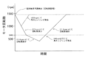
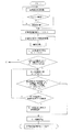
次に、本発明の遠心式液体ポンプ装置の作用を図7に示すタイミングチャートおよび図8、図9に示すフローチャートを用いて説明する。
磁気軸受ポンプは、例えば、1200rpm以上、具体的には、1450rpmで正常回転している。磁気軸受の制御系のトラブル発生(磁気軸受不調)、具体的には、図8のフローチャートに示すように、センサ断線もしくは電磁石断線であると判断されると、非常用回転制御モードがスタートする。そして、センサ断線もしくは電磁石断線であるとの判断時のモータ回転数が記憶される。
そして、電磁石の作動を停止し、磁気軸受を中止する。そして、モータの回転数を所定の低下度(第1の低下度、例えば、50〜400rpm/s、具体的には、217rpm/s)にて低下させる。この状態が、インペラ再カップリング試行ステップである。
【0027】
そして、所定モータ回転数に到達した時点においてモータ電流が所定値以上の場合、具体的には、1000rpmにおいてモータ電流が0.12A以上の場合には、インペラ再カップリングと判断する。
再カップリングと判断されると、図8に示すように、モータ回転数を所定の上昇度(第1の上昇度)、例えば、50〜400rpm/s、具体的には、217rpm/sにて上昇させる。そして、モータ回転数上昇ステップ中に、モータ回転数が所定値(第1の所定値)以上であってかつモータ電流が所定値以下の状態が所定時間継続したかどうか、具体的には、回転数が1300rpm以上でモータ電流が0.2A以下の状態が数秒間(例えば、4秒間以上の場合)継続したかどうかの判断、つまり、再カップリング離脱判断ステップを行い、そのような状態を検知することなく、モータ回転数が、記憶する不調検出時のモータ回転数に到達した場合には、モータ回転数の上昇を終了し、そのモータ回転数を維持する。これにより、動圧軸受による非接触回転への移行を完了する。
上記のケースにおけるタイミングチャートが、図7に示す破線の1000rpmにて再カップリング発生した場合である。
【0028】
なお、再カップリング離脱判断ステップ時に再カップリング離脱と判断されると、図8に示すようにモータ回転を停止する。そして、遠心式液体ポンプ装置が、非常用回転制御モード2を備える場合には、モード2に移行する。
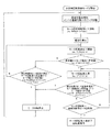
また、この実施例の遠心式液体ポンプ装置では、インペラ再カップリング試行ステップは、上記の第1の低下度による回転数低下中に上記の再カップリング条件を満たさなかった場合には、図9の▲1▼に移行し、さらに、モータ回転数の第1の低下度での低下を、モータ回転数が所定値(第2の所定値)、例えば500〜1000rpm、具体的には、640rpm以下となるまで継続する。そして、回転数が第2の所定値以下であることが検知されると、モータの回転数の低下度を第1の低下度より小さい第2の低下度、例えば、5〜100rpm/s、具体的には、13.6rpm/sに変更し、回転数低下を継続する。この状態もインペラ再カップリング試行ステップである。
【0029】
そして、この第2の低下度におけるインペラ再カップリング試行ステップ中に、モータ電流が所定の範囲内であることが検知された場合には、インペラ再カップリングと判断する。例えば、モータ電流が0.12〜2.72Aの範囲内であることが検知された場合には、インペラ再カップリングと判断する。
再カップリングと判断されると、図9に示すように、モータ回転数を所定の上昇度(上記の上昇度より小さい第2の上昇度)、例えば、5〜100rpm/s、具体的には、27.2rpm/sにて上昇させる。そして、モータ回転数上昇ステップ中に、モータ回転数が所定値(第1の所定値)以上であってかつモータ電流が所定値以下の状態が所定時間継続したかどうか、具体的には、回転数が1300rpm以上でモータ電流が0.2A以下の状態が数秒間(例えば、4秒間以上の場合)継続したかどうかの判断、つまり、再カップリング離脱判断ステップをし、そのような状態を検知することなく、モータ回転数が、記憶する不調検出時のモータ回転数に到達した場合には、モータ回転数の上昇を終了し、そのモータ回転数を維持する。このケースが、図7に実線で示すタイミングチャートのケースに該当する。
【0030】
また、上記の第2の低下度におけるインペラ再カップリング試行ステップは、そのステップ中に、モータ回転数が所定値(第2の所定値)未満であってかつモータ電流が所定値(第2の所定値)以上の状態が所定時間継続したかどうか、具体的には、回転数が640rpm未満でモータ電流が2.72Aより大きい状態が数秒間(例えば、4秒間以上の場合)継続したかどうかの判断、つまり、インペラ張り付き判断を行い、そのような状態を検知するまで、モータ回転数の低下を継続させるとともに、インペラ張り付きが判断された場合および上記の再カップリング離脱が判断された場合には、図9に示すようにモータ回転を停止する。そして、遠心式液体ポンプ装置が、非常用回転制御モード2を備える場合には、モード2に移行する。
【0031】
次に、図10に示す、非常用回転制御モード2について説明する。
非常用回転制御モード2に移行すると、図10に示すように、電磁石電流を上昇させて、インペラを電磁石側ハウジングの内面に接触(張り付け)させる。言い換えれば、インペラ電磁石側強制張付ステップを行う。電磁石のいずれか1つが故障した場合であっても、残りの電磁石を用いてこのような状態を形成することができる。そして、その状態にてモータを所定回転数、例えば、400〜800rpm、具体的には、640rpmにて回転させる。言い換えれば、インペラ電磁石側強制張付状態回転ステップを行う。
そして、電磁石の作動を停止し、モータの回転数を所定の低下度(第1の低下度より小さい第3の低下度、例えば、5〜100rpm/s、具体的には、13.6rpm/s)にて低下させる。この状態が、モード2におけるインペラ再カップリング試行ステップである。
【0032】
そして、この第3の低下度におけるインペラ再カップリング試行ステップ中に、モータ電流が所定の範囲内であることが検知された場合には、インペラ再カップリングと判断する。例えば、モータ電流が0.12〜2.72Aの範囲内であることが検知された場合には、インペラ再カップリングと判断する。
再カップリングと判断されると、図10に示すように、モータ回転数を所定の上昇度(上記の上昇度より小さい第2の上昇度)、例えば、5〜100rpm/s、具体的には、27.2rpm/sにて上昇させる。そして、モータ回転数上昇ステップ中に、モータ回転数が所定値(第1の所定値)以上であってかつモータ電流が所定値以下の状態が所定時間継続したかどうか、具体的には、回転数が1300rpm以上でモータ電流が0.2A以下の状態が数秒間(例えば、4秒間以上の場合)継続したかどうかの判断、つまり、再カップリング離脱判断ステップをし、そのような状態を検知することなく、モータ回転数が、記憶する不調検出時のモータ回転数に到達した場合には、モータ回転数の上昇を終了し、そのモータ回転数を維持する。
【0033】
また、上記の第3の低下度におけるインペラ再カップリング試行ステップは、そのステップ中に、モータ回転数が所定値(第2の所定値)未満であってかつモータ電流が所定値(第2の所定値)以上の状態が所定時間継続したかどうか、具体的には、回転数が640rpm未満でモータ電流が2.72Aより大きい状態が数秒間(例えば、4秒間以上の場合)継続したかどうかの判断、つまり、インペラ張り付き判断を行い、そのような状態を検知するまで、モータ回転数の低下継続させるとともに、インペラ張り付きが判断された場合および上記の再カップリング離脱が判断された場合には、図10に示すようにモータ回転を停止し、再度、モード2を最初から行う。つまり、動圧軸受支持によるインペラ回転が形成されるまで、上記の作業が繰り返して行われるように制御される。
また、遠心式液体ポンプ装置における非常用インペラ回転機能としては、図11に示すようなものでもよい。
【0034】
磁気軸受ポンプは、例えば、1200rpm以上、具体的には、1450rpmで正常回転している。磁気軸受の制御系のトラブル発生(磁気軸受不調)、具体的には、図11のフローチャートに示すように、センサ断線もしくは電磁石断線であると判断されると、非常用回転制御モードがスタートする。そして、センサ断線もしくは電磁石断線であるとの判断時のモータ回転数が記憶される。
そして、図11に示すように、電磁石電流を増加させて、インペラを電磁石側ハウジングの内面に接触(張り付け)させる。言い換えれば、インペラ電磁石側強制張付ステップを行う。電磁石のいずれか1つが故障した場合であっても、残りの電磁石を用いてこのような状態を形成することができる。そして、その状態にてモータを所定回転数、例えば、400〜800rpm、具体的には、640rpmにて回転させる。言い換えれば、インペラ電磁石側強制張付状態回転ステップを行う。
【0035】
そして、電磁石の作動を停止し、モータの回転数を所定の低下度(例えば、5〜100rpm/s、具体的には、13.6rpm/s)にて低下させる。この状態がインペラ再カップリング試行ステップである。
そして、このインペラ再カップリング試行ステップ中に、モータ電流が所定の範囲内であることが検知された場合には、インペラ再カップリングと判断する。例えば、モータ電流が0.12〜2.72Aの範囲内であることが検知された場合には、インペラ再カップリングと判断する。
再カップリングと判断されると、図11に示すように、モータ回転数を所定の上昇度、例えば、5〜100rpm/s、具体的には、27.2rpm/sにて上昇させる。そして、モータ回転数上昇ステップ中に、モータ回転数が所定値(第1の所定値)以上であってかつモータ電流が所定値以下の状態が所定時間継続したかどうか、具体的には、回転数が1300rpm以上でモータ電流が0.2A以下の状態が数秒間(例えば、4秒間以上の場合)継続したかどうかの判断、つまり、再カップリング離脱判断ステップをし、そのような状態を検知することなく、モータ回転数が、記憶する不調検出時のモータ回転数に到達した場合には、モータ回転数の上昇を終了し、そのモータ回転数を維持する。
【0036】
また、上記のインペラ再カップリング試行ステップは、そのステップ中に、モータ回転数が所定値(第2の所定値)未満であってかつモータ電流が所定値(第2の所定値)以上の状態が所定時間継続したかどうか、具体的には、回転数が640rpm未満でモータ電流が2.72Aより大きい状態が数秒間(例えば、4秒間以上の場合)継続したかどうかの判断、つまり、インペラ張り付き判断を行い、そのような状態を検知するまで、モータ回転数の低下継続させるとともに、インペラ張り付きが判断された場合および上記の再カップリング離脱が判断された場合には、図11に示すようにモータ回転を停止する。そして、再度、電磁石電流の増加によるインペラ張り付けステップに移行し、動圧溝によるインペラ回転が実現されるまで、上記の作業が繰り返して行われるように制御される。
【0037】
【発明の効果】
本発明の遠心式液体ポンプ装置は、液体流入ポートと液体流出ポートとを有するハウジングと、内部に第1の磁性体および第2の磁性体を備え、前記ハウジング内で回転し、回転時の遠心力によって液体を送液するインペラを有する遠心ポンプ部と、前記遠心ポンプ部の前記インペラの第1の磁性体を吸引するための磁石を備えるロータと、該ロータを回転させるモータを備えるインペラ回転トルク発生部と、前記インペラの第2の磁性体を吸引するための電磁石を備えるインペラ位置制御部と、前記インペラの位置を検出するための位置センサと、前記ロータ側のハウジング内面もしくは前記インペラの前記ロータ側の面に設けられた動圧溝を備え、前記ハウジングに対して磁気軸受によりインペラが非接触状態にて回転する遠心ポンプ装置本体部と、該遠心ポンプ装置本体部のための制御機構とを備える遠心式液体ポンプ装置である。
【0038】
そして、遠心式液体ポンプ装置が、位置センサ出力モニタリング機能と、モータ電流モニタリング機能を備え、前記位置センサ出力モニタリング機能を用いてセンサ不調を判断する不調検出機能とを備え、該不調検出機能によりセンサ不調検知時に作動し、前記ハウジングに対して前記動圧溝を利用して前記インペラを実質的に非接触状態にて回転させる非常用インペラ回転機能を備えるとともに、該非常用インペラ回転機能は、前記不調検出機能による不調を検知すると、前記電磁石によるインペラの吸引を停止し、モータの回転数を徐々に低下させることによりインペラとロータとの磁気的結合を試行させるインペラ再カップリング試行機能と、インペラ再カップリングを前記モータ電流モニタリング機能によるモータ電流を用いて検知する再カップリング検知機能と、該再カップリング検知機能による再カップリングの検知後に、モータ回転数を所定値まで上昇させるモータ回転数制御機能を備えることにより、磁気軸受の制御系の1つである位置センサにトラブルが生じた場合に、磁気軸受によるインペラの回転形態を動圧溝が発生する圧力を利用したインペラの回転に移行させることが可能であり、液体の送液を維持することを可能とする。
【0039】
また、遠心式液体ポンプ装置が、電磁石電流モニタリング機能と、モータ電流モニタリング機能を備え、前記電磁石電流モニタリング機能を用いて電磁石不調を判断する不調検出機能とを備え、該不調検出機能により電磁石の不調検知時に作動し、前記ハウジングに対して前記動圧溝を利用して前記インペラを実質的に非接触状態にて回転させる非常用インペラ回転機能を備えるとともに、該非常用インペラ回転機能は、前記不調検出機能による不調を検知すると、前記電磁石によるインペラの吸引を停止し、モータの回転数を徐々に低下させることによりインペラとロータとの磁気的結合を試行させるインペラ再カップリング試行機能と、インペラ再カップリングを前記モータ電流モニタリング機能によるモータ電流を用いて検知する再カップリング検知機能と、該再カップリング検知機能による再カップリングの検知後に、モータ回転数を所定値まで上昇させるモータ回転数制御機能を備えることにより、磁気軸受の制御系の1つである電磁石にトラブルが生じた場合に、磁気軸受によるインペラの回転形態を動圧溝が発生する圧力を利用したインペラの回転に移行させることが可能であり、液体の送液を維持することを可能とする。
【0040】
また、遠心式液体ポンプ装置が、位置センサ出力モニタリング機能と、電磁石電流モニタリング機能と、モータ電流モニタリング機能を備え、前記位置センサ出力モニタリング機能および前記電磁石電流モニタリング機能を用いてセンサ不調および電磁石不調を判断する不調検出機能とを備え、該不調検出機能によりセンサもしくは電磁石の不調検知時に作動し、前記ハウジングに対して前記動圧溝を利用して前記インペラを実質的に非接触状態にて回転させる非常用インペラ回転機能を備えるとともに、該非常用インペラ回転機能は、前記不調検出機能による不調を検知すると、前記電磁石によるインペラの吸引を停止し、モータの回転数を徐々に低下させることによりインペラとロータとの磁気的結合を試行させるインペラ再カップリング試行機能と、インペラ再カップリングを前記モータ電流モニタリング機能によるモータ電流を用いて検知する再カップリング検知機能と、該再カップリング検知機能による再カップリングの検知後に、モータ回転数を所定値まで上昇させるモータ回転数制御機能を備えることにより、磁気軸受の制御系の位置センサおよび電磁石にいずれかもしくは両者にトラブルが生じた場合に、磁気軸受によるインペラの回転形態を動圧溝が発生する圧力を利用したインペラの回転に移行させることが可能であり、液体の送液を維持することを可能とする。
【図面の簡単な説明】
【図1】図1は、本発明の遠心式液体ポンプ装置の実施例のブロック図である。
【図2】図2は、本発明の遠心式液体ポンプ装置に使用される遠心式液体ポンプ装置本体部の一例の正面図である。
【図3】図3は、図2に示した遠心式液体ポンプ装置本体部の平面図である。
【図4】図4は、図2に示した実施例の遠心式液体ポンプ装置本体部の縦断面図である。
【図5】図5は、図2の遠心式液体ポンプ装置本体部のA−A線断面図である。
【図6】図6は、図2の遠心式液体ポンプ装置本体部のA−A線断面図よりインペラを取り外した状態を示す断面図である。
【図7】図7は、本発明の一実施例の遠心式液体ポンプ装置の作用を説明するためのタイミングチャートである。
【図8】図8は、本発明の一実施例の遠心式液体ポンプ装置の作用を説明するためのフローチャートである。
【図9】図9は、本発明の一実施例の遠心式液体ポンプ装置の作用を説明するためのフローチャートである。
【図10】図10は、本発明の他の実施例の遠心式液体ポンプ装置の作用を説明するためのフローチャートである。
【図11】図11は、本発明の他の実施例の遠心式液体ポンプ装置の作用を説明するためのフローチャートである。
【符号の説明】
1 遠心式液体ポンプ装置
2 遠心式液体ポンプ部
3 インペラ回転トルク発生部
4 インペラ位置制御部
5 遠心式液体ポンプ装置本体部
6 制御機構
21 インペラ
25 磁性体
31 ロータ
34 モータ
41 電磁石[0001]
BACKGROUND OF THE INVENTION
The present invention relates to a centrifugal liquid pump device for feeding medical fluid such as blood.
[0002]
[Prior art]
Recently, an example of using a centrifugal blood pump for extracorporeal blood circulation in an oxygenator is increasing. Centrifugal pumps use a system that transmits driving torque from an external motor using magnetic coupling by completely eliminating physical communication between the outside and the blood chamber in the pump and preventing invasion of bacteria. Is used. Such a centrifugal blood pump has a housing having a blood inflow port and a blood outflow port, and an impeller that rotates in the housing and feeds blood by centrifugal force during rotation. Further, the impeller is rotated by a rotational torque generating mechanism that includes a permanent magnet inside and a rotor that includes a magnet for attracting the magnet of the impeller and a motor that rotates the rotor. The impeller is also attracted by the magnetic force on the side opposite to the rotor, and rotates in a non-contact state with respect to the housing. This state is called a magnetic levitation state.
[0003]
[Problems to be solved by the invention]
In a conventional centrifugal pump using a magnetic bearing, when trouble occurs in the control system of the magnetic bearing, the impeller cannot be rotated to maintain the pump function.
Usually, this magnetic levitation centrifugal pump includes three impeller position sensors and three impeller suction magnets. And the control of the magnetic bearing in the centrifugal pump controls the impeller position by controlling the electromagnet current based on the position sensor information of the impeller. Therefore, if the device constituting this control system is damaged, for example, if the position sensor cable or electromagnet cable is broken, trouble will occur in the control system, and correct control will not be possible, and the impeller will rotate on the magnetic bearing. It becomes difficult.
Accordingly, an object of the present invention is to provide a method for controlling the impeller substantially against the inner surface of the housing by using the pressure generated by the dynamic pressure groove if the motor can be controlled when trouble occurs in the control system of the magnetic bearing. Therefore, a centrifugal liquid pump device that can be rotated without being brought into contact with the liquid and can maintain liquid feeding is provided.
[0004]
[Means for Solving the Problems]
What achieves the above object is as follows.
(1) A housing having a liquid inflow port and a liquid outflow port, and a first magnetic body and a second magnetic body are provided therein, rotate inside the housing, and send liquid by centrifugal force during rotation. A centrifugal pump unit having an impeller, a rotor including a magnet for attracting the first magnetic body of the impeller of the centrifugal pump unit, an impeller rotational torque generating unit including a motor for rotating the rotor, and the impeller An impeller position control unit including an electromagnet for attracting the second magnetic body; a position sensor for detecting the position of the impeller; and a housing inner surface on the rotor side or a surface on the rotor side of the impeller. A centrifugal pump device main body that includes a hydrodynamic groove and the impeller rotates in a non-contact state with a magnetic bearing with respect to the housing; and the centrifugal pump device A centrifugal liquid pump device comprising a control mechanism for the main body,
The centrifugal liquid pump device has a position sensor output monitoring function and a motor current monitoring function. When , Malfunction detection function for judging sensor malfunction using the position sensor output monitoring function When The emergency impeller rotation function that operates when the sensor malfunction is detected by the malfunction detection function and rotates the impeller in a substantially non-contact state using the dynamic pressure groove with respect to the housing. When With
When the emergency impeller rotation function detects a malfunction by the malfunction detection function, the impeller suction by the electromagnet is stopped, and the rotational speed of the motor is gradually decreased to try magnetic coupling between the impeller and the rotor. An impeller recoupling trial function, a recoupling detection function for detecting impeller recoupling using a motor current by the motor current monitoring function, and a motor rotation speed after detection of recoupling by the recoupling detection function A centrifugal liquid pump device comprising a motor rotation speed control function for increasing the motor to a predetermined value.
[0005]
(2) A housing having a liquid inflow port and a liquid outflow port, and a first magnetic body and a second magnetic body are provided therein, rotate inside the housing, and send liquid by centrifugal force during rotation. A centrifugal pump unit having an impeller, a rotor including a magnet for attracting the first magnetic body of the impeller of the centrifugal pump unit, an impeller rotational torque generating unit including a motor for rotating the rotor, and the impeller An impeller position control unit including an electromagnet for attracting the second magnetic body; a position sensor for detecting the position of the impeller; and a housing inner surface on the rotor side or a surface on the rotor side of the impeller. A centrifugal pump device main body that includes a hydrodynamic groove and the impeller rotates in a non-contact state with a magnetic bearing with respect to the housing; and the centrifugal pump device A centrifugal liquid pump device comprising a control mechanism for the main body,
The centrifugal liquid pump device has an electromagnetic current monitoring function and a motor current monitoring function. When , Malfunction detection function for judging electromagnet malfunction using the electromagnet current monitoring function When The emergency impeller rotation function that operates when the malfunction of the electromagnet is detected by the malfunction detection function and rotates the impeller in a substantially non-contact state using the dynamic pressure groove with respect to the housing. When With
When the emergency impeller rotation function detects a malfunction by the malfunction detection function, the impeller suction by the electromagnet is stopped, and the rotational speed of the motor is gradually decreased to try magnetic coupling between the impeller and the rotor. An impeller recoupling trial function, a recoupling detection function for detecting impeller recoupling using a motor current by the motor current monitoring function, and a motor rotation speed after detection of recoupling by the recoupling detection function A centrifugal liquid pump device comprising a motor rotation speed control function for increasing the motor to a predetermined value.
[0006]
(3) A housing having a liquid inflow port and a liquid outflow port, and a first magnetic body and a second magnetic body are provided therein, rotate inside the housing, and send liquid by centrifugal force during rotation. A centrifugal pump unit having an impeller, a rotor including a magnet for attracting the first magnetic body of the impeller of the centrifugal pump unit, an impeller rotational torque generating unit including a motor for rotating the rotor, and the impeller An impeller position control unit including an electromagnet for attracting the second magnetic body; a position sensor for detecting the position of the impeller; and a housing inner surface on the rotor side or a surface on the rotor side of the impeller. A centrifugal pump device main body that includes a hydrodynamic groove and the impeller rotates in a non-contact state with a magnetic bearing with respect to the housing; and the centrifugal pump device A centrifugal liquid pump device comprising a control mechanism for the main body,
The centrifugal liquid pump device includes a position sensor output monitoring function, an electromagnet current monitoring function, and a motor current monitoring function. When , Malfunction detection function for judging sensor malfunction and electromagnet malfunction using the position sensor output monitoring function and the electromagnet current monitoring function When The emergency impeller rotating function that operates when the malfunction of the sensor or the electromagnet is detected by the malfunction detection function and rotates the impeller in a substantially non-contact state using the dynamic pressure groove with respect to the housing. When With
When the emergency impeller rotation function detects a malfunction by the malfunction detection function, the impeller suction by the electromagnet is stopped, and the rotational speed of the motor is gradually decreased to try magnetic coupling between the impeller and the rotor. An impeller recoupling trial function, a recoupling detection function for detecting impeller recoupling using a motor current by the motor current monitoring function, and a motor rotation speed after detection of recoupling by the recoupling detection function A centrifugal liquid pump device comprising a motor rotation speed control function for increasing the motor to a predetermined value.
[0007]
(4) The centrifugal liquid pump device includes a sensor circuit for the sensor, and the sensor circuit has a function of generating a predetermined value exceeding a normal level when disconnection occurs, and the malfunction detection function. Is a centrifugal liquid pump device according to (1) or (3), wherein a sensor malfunction is determined from an output value of the sensor by the sensor output monitoring function.
(5) The centrifugal liquid pump device includes an electromagnet circuit for the electromagnet, and the electromagnet circuit is turned off when an electromagnet breakage occurs. The centrifugal liquid pump device according to (2) or (3), wherein the electromagnet malfunction is determined from the electromagnet current non-conduction state by the electromagnet current monitoring function.
(6) When the emergency impeller rotation function detects a malfunction by the malfunction detection function, the impeller is brought into contact with the housing surface opposite to the rotor side by increasing the suction by the electromagnet before stopping the suction by the electromagnet The centrifugal liquid pump device according to any one of (1) to (5), wherein the centrifugal liquid pump device has a function of rotating the rotor.
(7) The centrifugal liquid pump device includes any one of the above (1) to (6) provided with a coupling detachment determining function that functions during motor rotation speed by the motor rotation speed control function after impeller recoupling. A centrifugal liquid pump device according to claim 1.
(8) The centrifugal liquid pump device according to (7), wherein the centrifugal liquid pump device stops the rotation of the motor when coupling separation is detected by the coupling separation determination function.
[0008]
(9) The second liquid impeller rotation that functions when the impeller is not recoupled by the impeller recoupling function or when the coupling detachment is detected by the coupling detachment function. The second emergency impeller rotating function is configured to increase the suction by the electromagnet and rotate the rotor while the impeller is in contact with the housing surface opposite to the rotor side, and then suck the impeller by the electromagnet. A second impeller recoupling trial function that stops and attempts to magnetically couple the impeller to the rotor by gradually reducing the number of revolutions of the motor, and after detection of recoupling by the recoupling detection function, (1) thru | or which raises a motor rotation speed to a predetermined value by the said motor rotation speed control function. The centrifugal liquid pump device according to any one of (8).
(10) The centrifugal liquid pump device includes a motor rotational speed storage function for storing a motor rotational speed at or near the malfunction detection by the malfunction detection function, and increases the motor rotational speed by the motor rotational speed control function. Is the centrifugal liquid pump device according to any one of the above (1) to (9), which increases the number of rotations stored by the motor rotation number storage function.
(11) The recoupling detection function according to any one of (1) to (10), wherein the recoupling detection function determines that recoupling is performed when a motor current at a predetermined number of rotations of the motor is equal to or greater than a predetermined value. Centrifugal liquid pump device.
(12) The impeller recoupling trial function includes a first rotational speed reduction step for continuously reducing the rotational speed of the motor at the first reduction degree to a predetermined rotational speed, and the first rotational speed reduction step. And when the impeller recoupling is not detected, a second rotation speed reduction step of continuously reducing the rotation speed of the motor with a second reduction degree that is lower than the first reduction degree is performed. The centrifugal liquid pump device according to any one of (1) to (11) above.
(13) The centrifugal type according to (12), wherein the recoupling detection function in the second rotation speed reduction step is to determine that recoupling is performed when the motor current falls within a predetermined range. Liquid pump device.
[0009]
DETAILED DESCRIPTION OF THE INVENTION
FIG. 1 is a block diagram of an embodiment of a centrifugal liquid pump apparatus according to the present invention. FIG. 2 is a front view of an example of a centrifugal liquid pump device main body used in the centrifugal liquid pump device of the present invention. FIG. 3 is a plan view of the centrifugal liquid pump device main body shown in FIG. 4 is a longitudinal sectional view of the centrifugal liquid pump device main body of the embodiment shown in FIG. FIG. 5 is a cross-sectional view taken along line AA of the centrifugal liquid pump device main body of FIG. 6 is a cross-sectional view showing a state where the impeller is removed from the cross-sectional view taken along the line AA of the centrifugal liquid pump device main body of FIG.
The centrifugal liquid pump device 1 of the present invention includes a
[0010]
The
Further, the
In particular, as shown in FIG. 1, the
[0011]
The centrifugal liquid pump device 1 is activated when a sensor malfunction is detected or an electromagnet malfunction is detected by the malfunction detection function, and the
When the emergency impeller rotation function detects a malfunction by the malfunction detection function, the impeller suction by the
In other words, the centrifugal liquid pump device 1 of the present invention has a function of shifting from non-contact rotation of the impeller by the magnetic bearing to non-contact rotation of the impeller by the dynamic pressure groove using the pressure generated by the dynamic pressure groove when the magnetic bearing is malfunctioning. I have.
In addition, in the rotation by the dynamic pressure groove, it is necessary to balance the suction force acting between the impeller and the rotor and the reverse pressure generated in the dynamic pressure groove, and for that purpose, coupling between the impeller and the rotor is essential. . Therefore, when trouble occurs in the control system of the magnetic bearing and the coupling is disengaged, it is not possible to shift to rotation by the dynamic pressure groove only by mechanically processing the dynamic pressure groove.
[0012]
Therefore, an explanation will be given using an embodiment of a centrifugal liquid pump apparatus of the type that includes both the position sensor
As shown in FIGS. 2 to 6, the centrifugal liquid pump device
[0013]
As shown in FIG. 4, the
The
[0014]
As shown in FIG. 5, a disc-
As shown in FIG. 4, a plurality (for example, 24 pieces) of first magnetic bodies 25 (permanent magnets, driven magnets) are embedded in the
[0015]
Further, by embedding a certain number of
Further, the
The impeller
[0016]
As shown in FIG. 4, the impeller rotational
The impeller rotational
[0017]
As shown in FIGS. 3 and 4, the impeller
The
[0018]
In the centrifugal liquid pump device 1 of this embodiment, as shown in FIG. 6, the
As shown in FIG. 6, the
The dynamic pressure groove may be provided on the rotor side surface of the
Because of having such a dynamic pressure groove, when the impeller position control unit is not in operation, it is sucked to the impeller rotational torque generating unit side, but between the
[0019]
The
The
In this embodiment, both the electromagnet current monitoring unit and the sensor output monitoring unit are provided, but only one of them may be provided.
The centrifugal liquid pump device 1 is activated when a sensor malfunction is detected or an electromagnet malfunction is detected by the malfunction detection function, and the
Therefore, the
[0020]
The centrifugal
In a magnetic bearing, when a failure occurs in the sensor system due to device breakage or cable disconnection, the sensor output deviates from the normal range. For example, when a disconnection occurs using a reluctance sensor, the sensor output deviates from the normal range.
For this reason, in the centrifugal liquid pump device of this embodiment, the sensor circuit for the sensor has a function of generating a predetermined value exceeding the normal level when a disconnection occurs. Specifically, the sensor circuit is a circuit that is set to +2.5 [V] (predetermined value) at the time of disconnection when the range that can normally be taken as the sensor output is −1 to +1 [V]. . For this reason, the malfunction detection function can easily and reliably determine sensor malfunction (disconnection) when the output value of the sensor by the sensor output monitoring function is the output value at the time of disconnection.
Similarly, the electromagnet current system deviates from the normal range when a failure due to device breakage or cable disconnection occurs. For this reason, in the centrifugal liquid pump device of this embodiment, an electromagnet circuit for an electromagnet is provided, and the electromagnet circuit that stops energization when the electromagnet is disconnected is used. Specifically, in the electromagnet circuit, the range that can normally be taken is 1 to 2 [A], but when the disconnection occurs, the electromagnet current is set to 0 [A]. For this reason, the malfunction detection function can easily and reliably determine electromagnet malfunction (disconnection) from the electromagnet current non-conduction state by the electromagnet current monitoring function.
[0021]
The centrifugal liquid pump device of this embodiment includes a plurality of electromagnets, and the electromagnet monitoring function monitors the current of each electromagnet. When any one of the electromagnets malfunctions, it is determined that the malfunction has occurred.
Similarly, the centrifugal liquid pump device of this embodiment includes a plurality of position sensors, and the sensor output monitoring function monitors the output of each sensor. When any one of the sensors malfunctions, the sensor is determined to be malfunctioning.
A dynamic pressure bearing constituted by a dynamic pressure groove is a system in which non-contact is maintained by pressure generated in the groove. However, in order to generate pressure, the impeller needs to rotate at a certain rotational speed or more, and for this purpose, the coupling between the impeller and the rotor must be normal. If a failure occurs in the magnetic bearing control system, the impeller and rotor coupling will not be normal, so recoupling is required. The centrifugal liquid pump device according to the present invention has a structure capable of stable impeller non-contact rotation by a dynamic pressure groove at an impeller rotational speed (rotor rotational speed) of 1000 to 3000 rpm.
[0022]
The impeller recoupling trial function that operates after malfunction detection will be described.
In the centrifugal liquid pump device of the present invention, when the malfunction is detected by the malfunction detection function, the suction of the impeller by the
Further, the impeller recoupling trial function includes a first rotational speed reduction step for continuously reducing the rotational speed of the motor at the first reduction degree to a predetermined rotational speed, and the impeller in the first rotational speed reduction step. When re-coupling is not detected, a second rotation speed reduction step of continuously reducing the rotation speed of the motor with a second reduction degree that is lower than the first reduction degree is performed. Is preferred.
The recoupling detection function detects the impeller recoupling by using the motor current by the motor current monitoring function. Specifically, when the recoupling between the
[0023]
And the centrifugal liquid pump apparatus of this invention is equipped with the motor rotation speed control function which act | operates after said recoupling detection. In the motor rotation speed control function for detecting the re-coupling, the motor rotation speed is increased to a predetermined value (at least until the substantially non-contact rotation by the dynamic pressure groove is enabled).
Particularly preferably, the centrifugal liquid pump device has a motor rotation speed storage function for storing the motor rotation speed at or near the malfunction detection by the malfunction detection function, and the motor rotation speed control function by the motor rotation speed control function described above. It is preferable that the increase is to increase the rotational speed stored by the motor rotational speed storage function.
Further, as an emergency impeller rotating function of the centrifugal liquid pump device, when the malfunction of the
[0024]
Furthermore, the centrifugal liquid pump device preferably has a coupling detachment determination function that functions during motor rotation by the motor rotation speed control function when ascending by the hydrodynamic bearing after impeller recoupling. The coupling detachment determination function can be determined, for example, by determining that the motor rotational speed is greater than a predetermined value and the motor current is smaller than a predetermined value during a predetermined time. Specifically, a motor current value (for example, 0.12 A) at a predetermined motor rotation number (for example, 1000 rpm) is stored, and the motor is in spite of the fact that the actual motor rotation state is larger than the above rotation number. When the current is smaller than the motor current value, it is determined that the impeller and the rotor are separated from each other.
[0025]
The centrifugal liquid pump device preferably stops the rotation of the motor when coupling separation is detected by the coupling separation determination function.
Further, the centrifugal liquid pump device has a second emergency impeller rotation function that functions when the impeller is not recoupled by the impeller recoupling function or when the coupling is detached after the impeller recoupling once. It is preferable to provide.
As a second emergency impeller rotation function, the suction of the
[0026]
Next, the operation of the centrifugal liquid pump apparatus of the present invention will be described with reference to the timing chart shown in FIG. 7 and the flowcharts shown in FIGS.
The magnetic bearing pump normally rotates at, for example, 1200 rpm or more, specifically, 1450 rpm. When a trouble occurs in the control system of the magnetic bearing (magnetic bearing malfunction), specifically, as shown in the flowchart of FIG. 8, the emergency rotation control mode starts when it is determined that the sensor is broken or the electromagnet is broken. And the motor rotation speed at the time of judging that it is a sensor disconnection or an electromagnet disconnection is memorize | stored.
Then, the operation of the electromagnet is stopped and the magnetic bearing is stopped. Then, the rotational speed of the motor is reduced at a predetermined reduction degree (first reduction degree, for example, 50 to 400 rpm / s, specifically, 217 rpm / s). This state is an impeller recoupling trial step.
[0027]
When the motor current is equal to or greater than a predetermined value when the predetermined motor speed is reached, specifically, when the motor current is equal to or greater than 0.12 A at 1000 rpm, it is determined that the impeller is recoupled.
When it is determined that recoupling is performed, as shown in FIG. 8, the motor rotational speed is set at a predetermined increase (first increase), for example, 50 to 400 rpm / s, specifically 217 rpm / s. Raise. Then, during the motor rotation speed increasing step, whether or not the motor rotation speed is equal to or greater than a predetermined value (first predetermined value) and the motor current is equal to or less than the predetermined value continues for a predetermined time. Judgment whether or not the state where the number is 1300 rpm or more and the motor current is 0.2 A or less has continued for several seconds (for example, 4 seconds or more), that is, a recoupling separation determination step is performed, and such a state is detected. If the motor rotational speed reaches the motor rotational speed at the time of malfunction detection stored, the increase in the motor rotational speed is terminated and the motor rotational speed is maintained. This completes the transition to non-contact rotation by the hydrodynamic bearing.
The timing chart in the above case is a case where recoupling occurs at 1000 rpm of the broken line shown in FIG.
[0028]
If it is determined that the recoupling is separated at the recoupling separation determining step, the motor rotation is stopped as shown in FIG. When the centrifugal liquid pump device includes the emergency
Further, in the centrifugal liquid pump device of this embodiment, when the impeller recoupling trial step does not satisfy the recoupling condition during the rotation speed reduction due to the first reduction degree, FIG. Further, when the motor rotational speed is reduced to the first reduction degree, the motor rotational speed is a predetermined value (second predetermined value), for example, 500 to 1000 rpm, specifically, 640 rpm or less. Continue until When it is detected that the rotation speed is equal to or less than the second predetermined value, the motor rotation speed is reduced to a second reduction degree smaller than the first reduction degree, for example, 5 to 100 rpm / s, specifically Specifically, the speed is changed to 13.6 rpm / s and the rotation speed reduction is continued. This state is also an impeller recoupling trial step.
[0029]
Then, when it is detected that the motor current is within the predetermined range during the impeller recoupling trial step at the second reduction degree, it is determined that the impeller is recoupled. For example, when it is detected that the motor current is within the range of 0.12 to 2.72 A, it is determined that the impeller is recoupled.
When it is determined that re-coupling is performed, as shown in FIG. 9, the motor rotational speed is increased to a predetermined increase degree (second increase degree smaller than the above increase degree), for example, 5 to 100 rpm / s, specifically , 27.2 rpm / s. Then, during the motor rotation speed increasing step, whether or not the motor rotation speed is equal to or greater than a predetermined value (first predetermined value) and the motor current is equal to or less than the predetermined value continues for a predetermined time. Judgment whether or not the state where the number is 1300 rpm or more and the motor current is 0.2 A or less has continued for several seconds (for example, when it is 4 seconds or more), that is, a recoupling separation determination step is performed, and such a state is detected. If the motor rotational speed reaches the motor rotational speed at the time of malfunction detection stored, the increase in the motor rotational speed is terminated and the motor rotational speed is maintained. This case corresponds to the case of the timing chart shown by the solid line in FIG.
[0030]
In the impeller recoupling trial step at the second degree of decrease, the motor rotational speed is less than a predetermined value (second predetermined value) and the motor current is a predetermined value (second Whether or not a state above (predetermined value) has continued for a predetermined time, specifically, whether or not a state in which the rotation speed is less than 640 rpm and the motor current is greater than 2.72 A has continued for several seconds (for example, for 4 seconds or more) In other words, the impeller sticking judgment is made and the motor rotation speed is continuously lowered until such a state is detected, and when the impeller sticking is judged and when the above-mentioned re-coupling is judged. Stops the motor rotation as shown in FIG. When the centrifugal liquid pump device includes the emergency
[0031]
Next, emergency
When the emergency
Then, the operation of the electromagnet is stopped, and the rotational speed of the motor is reduced to a predetermined reduction degree (a third reduction degree smaller than the first reduction degree, for example, 5 to 100 rpm / s, specifically 13.6 rpm / s. ). This state is the impeller recoupling trial step in
[0032]
If it is detected that the motor current is within the predetermined range during the impeller recoupling trial step at the third degree of decrease, it is determined that the impeller is recoupled. For example, when it is detected that the motor current is within the range of 0.12 to 2.72 A, it is determined that the impeller is recoupled.
When it is determined that the re-coupling is performed, as shown in FIG. 10, the motor rotational speed is increased to a predetermined increase degree (second increase degree smaller than the above increase degree), for example, 5 to 100 rpm / s, specifically , 27.2 rpm / s. Then, during the motor rotation speed increasing step, whether or not the motor rotation speed is equal to or greater than a predetermined value (first predetermined value) and the motor current is equal to or less than the predetermined value has been continued. Judgment whether or not the state where the number is 1300 rpm or more and the motor current is 0.2 A or less has continued for several seconds (for example, 4 seconds or more), that is, a recoupling separation determination step is performed, and such a state is detected. If the motor rotational speed reaches the motor rotational speed at the time of malfunction detection stored, the increase in the motor rotational speed is terminated and the motor rotational speed is maintained.
[0033]
Further, the impeller recoupling trial step at the third degree of reduction described above includes a step in which the motor rotational speed is less than a predetermined value (second predetermined value) and the motor current is a predetermined value (second Whether or not a state above (predetermined value) has continued for a predetermined time, specifically, whether or not a state in which the rotation speed is less than 640 rpm and the motor current is greater than 2.72 A has continued for several seconds (for example, for 4 seconds or more) In other words, the impeller sticking judgment is made, and the motor rotation speed continues to be lowered until such a state is detected, and when the impeller sticking is judged and when the above-mentioned recoupling is removed As shown in FIG. 10, the motor rotation is stopped and
Further, the emergency impeller rotating function in the centrifugal liquid pump device may be as shown in FIG.
[0034]
The magnetic bearing pump normally rotates at, for example, 1200 rpm or more, specifically, 1450 rpm. When a trouble occurs in the control system of the magnetic bearing (magnetic bearing malfunction), specifically, as shown in the flowchart of FIG. 11, the emergency rotation control mode starts when it is determined that the sensor is broken or the electromagnet is broken. And the motor rotation speed at the time of judging that it is a sensor disconnection or an electromagnet disconnection is memorize | stored.
Then, as shown in FIG. 11, the electromagnet current is increased, and the impeller is brought into contact (pasted) with the inner surface of the electromagnet side housing. In other words, the impeller electromagnet side forced tensioning step is performed. Even if any one of the electromagnets fails, such a state can be formed using the remaining electromagnets. In this state, the motor is rotated at a predetermined rotation speed, for example, 400 to 800 rpm, specifically, 640 rpm. In other words, the impeller electromagnet side forced tension state rotation step is performed.
[0035]
Then, the operation of the electromagnet is stopped, and the rotational speed of the motor is reduced at a predetermined reduction rate (for example, 5 to 100 rpm / s, specifically 13.6 rpm / s). This state is an impeller recoupling trial step.
When it is detected during the impeller recoupling trial step that the motor current is within a predetermined range, it is determined that the impeller is recoupled. For example, when it is detected that the motor current is within the range of 0.12 to 2.72 A, it is determined that the impeller is recoupled.
If it is determined that re-coupling is performed, as shown in FIG. 11, the motor rotational speed is increased at a predetermined increase rate, for example, 5 to 100 rpm / s, specifically 27.2 rpm / s. Then, during the motor rotation speed increasing step, whether or not the motor rotation speed is equal to or greater than a predetermined value (first predetermined value) and the motor current is equal to or less than the predetermined value continues for a predetermined time. Judgment whether or not the state where the number is 1300 rpm or more and the motor current is 0.2 A or less has continued for several seconds (for example, when it is 4 seconds or more), that is, a recoupling separation determination step is performed, and such a state is detected. If the motor rotational speed reaches the motor rotational speed at the time of malfunction detection stored, the increase in the motor rotational speed is terminated and the motor rotational speed is maintained.
[0036]
In the impeller recoupling trial step, the motor rotation speed is less than a predetermined value (second predetermined value) and the motor current is equal to or higher than a predetermined value (second predetermined value) during the step. Is determined for a predetermined time, specifically, whether or not the state where the rotational speed is less than 640 rpm and the motor current is larger than 2.72 A is continued for a few seconds (for example, 4 seconds or more), that is, the impeller When the sticking judgment is performed and the motor rotation speed is continuously lowered until such a state is detected, and when the impeller sticking is judged and when the above-described re-coupling is judged as shown in FIG. Stop motor rotation. Then, again, the operation proceeds to the impeller attaching step by increasing the electromagnet current, and the above operation is controlled to be repeated until the impeller rotation by the dynamic pressure groove is realized.
[0037]
【The invention's effect】
A centrifugal liquid pump device according to the present invention includes a housing having a liquid inflow port and a liquid outflow port, and a first magnetic body and a second magnetic body therein, and the centrifugal liquid pump rotates when rotating inside the housing. Impeller rotational torque comprising a centrifugal pump unit having an impeller for feeding liquid by force, a rotor having a magnet for attracting the first magnetic body of the impeller of the centrifugal pump unit, and a motor for rotating the rotor A generator, an impeller position control unit including an electromagnet for attracting a second magnetic body of the impeller, a position sensor for detecting the position of the impeller, the inner surface of the housing on the rotor side, or the impeller A centrifugal pump device having a dynamic pressure groove provided on the rotor side surface, wherein the impeller rotates in a non-contact state by a magnetic bearing with respect to the housing. A body portion, a centrifugal fluid pump apparatus and a control mechanism for the centrifugal pump main unit.
[0038]
The centrifugal liquid pump device includes a position sensor output monitoring function, a motor current monitoring function, and a malfunction detection function that determines sensor malfunction using the position sensor output monitoring function. The emergency impeller rotation function operates at the time of malfunction detection and rotates the impeller in a substantially non-contact state using the dynamic pressure groove with respect to the housing. When a malfunction is detected by the malfunction detection function, an impeller recoupling trial function that stops the attraction of the impeller by the electromagnet and attempts to magnetically couple the impeller and the rotor by gradually reducing the rotational speed of the motor, and the impeller Re-coupling is detected using the motor current by the motor current monitoring function. In one of the control systems of the magnetic bearing, a re-coupling detection function and a motor rotation speed control function for increasing the motor rotation speed to a predetermined value after detection of re-coupling by the re-coupling detection function are provided. When trouble occurs in a certain position sensor, it is possible to shift the rotation mode of the impeller by the magnetic bearing to the rotation of the impeller using the pressure generated by the dynamic pressure groove, and to maintain liquid feeding Make it possible.
[0039]
Further, the centrifugal liquid pump device has an electromagnet current monitoring function and a motor current monitoring function, and a malfunction detection function for judging an electromagnet malfunction using the electromagnet current monitoring function. The emergency impeller rotation function that operates at the time of detection and rotates the impeller in a substantially non-contact state using the dynamic pressure groove with respect to the housing. When a malfunction due to the detection function is detected, an impeller recoupling trial function that stops the attraction of the impeller by the electromagnet and attempts to magnetically couple the impeller and the rotor by gradually reducing the rotational speed of the motor, Recovering the coupling using the motor current by the motor current monitoring function. An electromagnet, which is one of the control systems for magnetic bearings, is provided with a pulling detection function and a motor rotation speed control function that raises the motor rotation speed to a predetermined value after detection of recoupling by the recoupling detection function. When trouble occurs, it is possible to shift the rotation mode of the impeller by the magnetic bearing to the rotation of the impeller using the pressure generated by the dynamic pressure grooves, and it is possible to maintain liquid feeding.
[0040]
Further, the centrifugal liquid pump device has a position sensor output monitoring function, an electromagnet current monitoring function, and a motor current monitoring function, and the sensor malfunction and electromagnet malfunction are detected using the position sensor output monitoring function and the electromagnet current monitoring function. A malfunction detection function for judging, and the malfunction detection function operates when malfunction of a sensor or an electromagnet is detected, and the impeller is rotated in a substantially non-contact state with respect to the housing using the dynamic pressure groove. An emergency impeller rotation function is provided, and when the emergency impeller rotation function detects a malfunction by the malfunction detection function, the impeller is stopped by sucking the impeller by the electromagnet, and the rotation speed of the motor is gradually decreased. Impeller recoupling to attempt magnetic coupling with the rotor After the trial function, the recoupling detection function for detecting the impeller recoupling using the motor current by the motor current monitoring function, and the recoupling detection by the recoupling detection function, the motor rotation speed is reduced to a predetermined value. By providing a motor speed control function that raises the pressure, the pressure generated by the dynamic pressure groove in the rotating form of the impeller by the magnetic bearing should a trouble occur in either or both of the position sensor and electromagnet of the magnetic bearing control system. It is possible to shift to the rotation of the impeller using the, and it is possible to maintain the liquid feeding.
[Brief description of the drawings]
FIG. 1 is a block diagram of an embodiment of a centrifugal liquid pump apparatus according to the present invention.
FIG. 2 is a front view of an example of a main body of a centrifugal liquid pump device used in the centrifugal liquid pump device of the present invention.
FIG. 3 is a plan view of the centrifugal liquid pump device main body shown in FIG. 2;
4 is a longitudinal sectional view of the centrifugal liquid pump device main body of the embodiment shown in FIG. 2. FIG.
5 is a cross-sectional view taken along the line AA of the centrifugal liquid pump device main body of FIG. 2. FIG.
6 is a cross-sectional view showing a state in which an impeller is removed from a cross-sectional view taken along line AA of the centrifugal liquid pump device main body in FIG. 2. FIG.
FIG. 7 is a timing chart for explaining the operation of the centrifugal liquid pump device according to the embodiment of the present invention.
FIG. 8 is a flowchart for explaining the operation of the centrifugal liquid pump device according to the embodiment of the present invention.
FIG. 9 is a flowchart for explaining the operation of the centrifugal liquid pump device according to the embodiment of the present invention.
FIG. 10 is a flowchart for explaining the operation of a centrifugal liquid pump apparatus according to another embodiment of the present invention.
FIG. 11 is a flowchart for explaining the operation of a centrifugal liquid pump device according to another embodiment of the present invention.
[Explanation of symbols]
1 Centrifugal liquid pump device
2 Centrifugal liquid pump
3 Impeller rotational torque generator
4 Impeller position controller
5 Centrifugal liquid pump device body
6 Control mechanism
21 Impeller
25 Magnetic material
31 rotor
34 Motor
41 electromagnet
Claims (13)
該遠心式液体ポンプ装置は、位置センサ出力モニタリング機能と、モータ電流モニタリング機能と、前記位置センサ出力モニタリング機能を用いてセンサ不調を判断する不調検出機能と、該不調検出機能によりセンサ不調検知時に作動し、前記ハウジングに対して前記動圧溝を利用して前記インペラを実質的に非接触状態にて回転させる非常用インペラ回転機能とを備えるとともに、
該非常用インペラ回転機能は、前記不調検出機能による不調を検知すると、前記電磁石によるインペラの吸引を停止し、モータの回転数を徐々に低下させることによりインペラとロータとの磁気的結合を試行させるインペラ再カップリング試行機能と、インペラ再カップリングを前記モータ電流モニタリング機能によるモータ電流を用いて検知する再カップリング検知機能と、該再カップリング検知機能による再カップリングの検知後に、モータ回転数を所定値まで上昇させるモータ回転数制御機能とを備えることを特徴とする遠心式液体ポンプ装置。A housing having a liquid inflow port and a liquid outflow port, and an impeller that includes a first magnetic body and a second magnetic body inside, rotates inside the housing, and feeds liquid by centrifugal force during rotation. A centrifugal pump unit; a rotor including a magnet for attracting the first magnetic body of the impeller of the centrifugal pump unit; an impeller rotational torque generating unit including a motor that rotates the rotor; and a second of the impeller An impeller position control unit including an electromagnet for attracting a magnetic material, a position sensor for detecting the position of the impeller, and a dynamic pressure provided on the inner surface of the housing on the rotor side or on the rotor side surface of the impeller A centrifugal pump device main body having a groove and rotating the impeller in a non-contact state by a magnetic bearing with respect to the housing; and the centrifugal pump device main body A centrifugal fluid pump apparatus and a control mechanism for,
Centrifugal fluid pump apparatus, operating a position sensor output monitoring function, and the motor current monitoring function, the irregularity-detection function of determining malfunction sensor using said position sensor output monitoring function, when the sensor malfunction detection by said non-tone detection function and provided with a substantially emergency impeller rotation function of rotating in a non-contact state said impeller by utilizing said hydrodynamic grooves relative to the housing,
When the emergency impeller rotation function detects a malfunction by the malfunction detection function, the impeller suction by the electromagnet is stopped, and the rotational speed of the motor is gradually decreased to try magnetic coupling between the impeller and the rotor. An impeller recoupling trial function, a recoupling detection function for detecting impeller recoupling using a motor current by the motor current monitoring function, and a motor rotation speed after detection of recoupling by the recoupling detection function A centrifugal liquid pump device comprising a motor rotation speed control function for increasing the motor to a predetermined value.
該遠心式液体ポンプ装置は、電磁石電流モニタリング機能と、モータ電流モニタリング機能と、前記電磁石電流モニタリング機能を用いて電磁石不調を判断する不調検出機能と、該不調検出機能により電磁石の不調検知時に作動し、前記ハウジングに対して前記動圧溝を利用して前記インペラを実質的に非接触状態にて回転させる非常用インペラ回転機能とを備えるとともに、
該非常用インペラ回転機能は、前記不調検出機能による不調を検知すると、前記電磁石によるインペラの吸引を停止し、モータの回転数を徐々に低下させることによりインペラとロータとの磁気的結合を試行させるインペラ再カップリング試行機能と、インペラ再カップリングを前記モータ電流モニタリング機能によるモータ電流を用いて検知する再カップリング検知機能と、該再カップリング検知機能による再カップリングの検知後に、モータ回転数を所定値まで上昇させるモータ回転数制御機能とを備えることを特徴とする遠心式液体ポンプ装置。A housing having a liquid inflow port and a liquid outflow port, and an impeller that includes a first magnetic body and a second magnetic body inside, rotates inside the housing, and feeds liquid by centrifugal force during rotation. A centrifugal pump unit; a rotor including a magnet for attracting the first magnetic body of the impeller of the centrifugal pump unit; an impeller rotational torque generating unit including a motor that rotates the rotor; and a second of the impeller An impeller position control unit including an electromagnet for attracting a magnetic material, a position sensor for detecting the position of the impeller, and a dynamic pressure provided on the inner surface of the housing on the rotor side or on the rotor side surface of the impeller A centrifugal pump device main body having a groove and rotating the impeller in a non-contact state by a magnetic bearing with respect to the housing; and the centrifugal pump device main body A centrifugal fluid pump apparatus and a control mechanism for,
Centrifugal fluid pump assembly includes an electromagnet current monitoring function operates a motor current monitoring function, the irregularity-detection function of determining malfunction electromagnet using the electromagnet current monitoring function, by said non-tone detection function when malfunction detection of the electromagnet provided with a substantially emergency impeller rotation function of rotating in a non-contact state said impeller by utilizing said hydrodynamic grooves relative to the housing,
When the emergency impeller rotation function detects a malfunction by the malfunction detection function, the impeller suction by the electromagnet is stopped, and the rotational speed of the motor is gradually decreased to try magnetic coupling between the impeller and the rotor. An impeller recoupling trial function, a recoupling detection function for detecting impeller recoupling using a motor current by the motor current monitoring function, and a motor rotation speed after detection of recoupling by the recoupling detection function A centrifugal liquid pump device comprising a motor rotation speed control function for increasing the motor to a predetermined value.
該遠心式液体ポンプ装置は、位置センサ出力モニタリング機能と、電磁石電流モニタリング機能と、モータ電流モニタリング機能と、前記位置センサ出力モニタリング機能および前記電磁石電流モニタリング機能を用いてセンサ不調および電磁石不調を判断する不調検出機能と、該不調検出機能によりセンサもしくは電磁石の不調検知時に作動し、前記ハウジングに対して前記動圧溝を利用して前記インペラを実質的に非接触状態にて回転させる非常用インペラ回転機能とを備えるとともに、
該非常用インペラ回転機能は、前記不調検出機能による不調を検知すると、前記電磁石によるインペラの吸引を停止し、モータの回転数を徐々に低下させることによりインペラとロータとの磁気的結合を試行させるインペラ再カップリング試行機能と、インペラ再カップリングを前記モータ電流モニタリング機能によるモータ電流を用いて検知する再カップリング検知機能と、該再カップリング検知機能による再カップリングの検知後に、モータ回転数を所定値まで上昇させるモータ回転数制御機能とを備えることを特徴とする遠心式液体ポンプ装置。A housing having a liquid inflow port and a liquid outflow port, and an impeller that includes a first magnetic body and a second magnetic body inside, rotates inside the housing, and feeds liquid by centrifugal force during rotation. A centrifugal pump unit; a rotor including a magnet for attracting the first magnetic body of the impeller of the centrifugal pump unit; an impeller rotational torque generating unit including a motor that rotates the rotor; and a second of the impeller An impeller position control unit including an electromagnet for attracting a magnetic material, a position sensor for detecting the position of the impeller, and a dynamic pressure provided on the inner surface of the housing on the rotor side or on the rotor side surface of the impeller A centrifugal pump device main body having a groove and rotating the impeller in a non-contact state by a magnetic bearing with respect to the housing; and the centrifugal pump device main body A centrifugal fluid pump apparatus and a control mechanism for,
The centrifugal liquid pump device determines a sensor malfunction and an electromagnet malfunction using the position sensor output monitoring function, the electromagnet current monitoring function, the motor current monitoring function , the position sensor output monitoring function, and the electromagnet current monitoring function. A malfunction detection function, and an emergency impeller rotation that operates when a malfunction of a sensor or an electromagnet is detected by the malfunction detection function and rotates the impeller in a substantially non-contact state with respect to the housing using the dynamic pressure groove. features and provided with a,
When the emergency impeller rotation function detects a malfunction by the malfunction detection function, the impeller suction by the electromagnet is stopped, and the rotational speed of the motor is gradually decreased to try magnetic coupling between the impeller and the rotor. An impeller recoupling trial function, a recoupling detection function for detecting impeller recoupling using a motor current by the motor current monitoring function, and a motor rotation speed after detection of recoupling by the recoupling detection function A centrifugal liquid pump device comprising a motor rotation speed control function for increasing the motor to a predetermined value.
Priority Applications (5)
| Application Number | Priority Date | Filing Date | Title |
|---|---|---|---|
| JP2002002584A JP3996775B2 (en) | 2002-01-09 | 2002-01-09 | Centrifugal liquid pump device |
| DE60310778T DE60310778T2 (en) | 2002-01-09 | 2003-01-07 | Centrifugal pump with fault correction |
| EP03000186A EP1327455B1 (en) | 2002-01-09 | 2003-01-07 | Centrifugal fluid pump with failure correction |
| AT03000186T ATE350080T1 (en) | 2002-01-09 | 2003-01-07 | CENTRIFUGA PUMP WITH FAULT CORRECTION |
| US10/338,712 US6840735B2 (en) | 2002-01-09 | 2003-01-09 | Centrifugal fluid pump apparatus |
Applications Claiming Priority (1)
| Application Number | Priority Date | Filing Date | Title |
|---|---|---|---|
| JP2002002584A JP3996775B2 (en) | 2002-01-09 | 2002-01-09 | Centrifugal liquid pump device |
Publications (2)
| Publication Number | Publication Date |
|---|---|
| JP2003201992A JP2003201992A (en) | 2003-07-18 |
| JP3996775B2 true JP3996775B2 (en) | 2007-10-24 |
Family
ID=19190762
Family Applications (1)
| Application Number | Title | Priority Date | Filing Date |
|---|---|---|---|
| JP2002002584A Expired - Fee Related JP3996775B2 (en) | 2002-01-09 | 2002-01-09 | Centrifugal liquid pump device |
Country Status (5)
| Country | Link |
|---|---|
| US (1) | US6840735B2 (en) |
| EP (1) | EP1327455B1 (en) |
| JP (1) | JP3996775B2 (en) |
| AT (1) | ATE350080T1 (en) |
| DE (1) | DE60310778T2 (en) |
Families Citing this family (44)
| Publication number | Priority date | Publication date | Assignee | Title |
|---|---|---|---|---|
| EP1430919A1 (en) | 2002-12-17 | 2004-06-23 | Terumo Kabushiki Kaisha | Centrifugal blood pump apparatus |
| US7488448B2 (en) * | 2004-03-01 | 2009-02-10 | Indian Wells Medical, Inc. | Method and apparatus for removal of gas bubbles from blood |
| JP4767488B2 (en) * | 2003-10-23 | 2011-09-07 | Ntn株式会社 | Magnetic levitation pump |
| ATE456963T1 (en) | 2004-03-24 | 2010-02-15 | Terumo Corp | CENTRIFUGAL BLOOD PUMP WITH HYDRODYNAMIC STORAGE |
| TW200711557A (en) * | 2005-09-02 | 2007-03-16 | Sunonwealth Electr Mach Ind Co | Heat dissipation device |
| US20070177995A1 (en) * | 2006-02-01 | 2007-08-02 | Yoshio Yano | Pump device |
| US20070183908A1 (en) * | 2006-02-06 | 2007-08-09 | Yoshio Yano | Contactless centrifugal pump |
| US20070224059A1 (en) * | 2006-03-23 | 2007-09-27 | Cheng-Tien Lai | Miniature pump for liquid cooling system |
| JP4898319B2 (en) | 2006-06-23 | 2012-03-14 | テルモ株式会社 | Blood pump device |
| US9044535B2 (en) * | 2007-08-07 | 2015-06-02 | Terumo Cardiovascular Systems Corp. | Extracorporeal blood pump with disposable pump head portion having magnetically levitated impeller |
| JP5015985B2 (en) * | 2009-03-19 | 2012-09-05 | テルモ株式会社 | Centrifugal blood pump device |
| CN102686282B (en) | 2009-11-19 | 2014-10-01 | 瑞思迈发动机及马达技术股份有限公司 | Blower |
| JP5577506B2 (en) | 2010-09-14 | 2014-08-27 | ソーラテック コーポレイション | Centrifugal pump device |
| EP2693609B1 (en) | 2011-03-28 | 2017-05-03 | Thoratec Corporation | Rotation and drive device and centrifugal pump device using same |
| US10260507B2 (en) * | 2011-08-23 | 2019-04-16 | Moog Inc. | Magnetically coupled pump assembly |
| GB201218768D0 (en) * | 2012-10-18 | 2012-12-05 | Calon Cardio Technology Ltd | Centrifugal pumps |
| US9371826B2 (en) | 2013-01-24 | 2016-06-21 | Thoratec Corporation | Impeller position compensation using field oriented control |
| US9556873B2 (en) | 2013-02-27 | 2017-01-31 | Tc1 Llc | Startup sequence for centrifugal pump with levitated impeller |
| CN110332138A (en) * | 2013-03-21 | 2019-10-15 | 北京奇宏科技研发中心有限公司 | The monitoring device in fan spindle bearing service life |
| US10052420B2 (en) | 2013-04-30 | 2018-08-21 | Tc1 Llc | Heart beat identification and pump speed synchronization |
| DE102013017828B4 (en) * | 2013-10-24 | 2015-05-13 | Fresenius Medical Care Deutschland Gmbh | Method and device for monitoring an in an extracorporeal blood circulation or arranged in a Dialysatkreislauf impeller pump and blood treatment device |
| US9623161B2 (en) | 2014-08-26 | 2017-04-18 | Tc1 Llc | Blood pump and method of suction detection |
| EP3256183A4 (en) | 2015-02-11 | 2018-09-19 | Tc1 Llc | Heart beat identification and pump speed synchronization |
| US10166318B2 (en) | 2015-02-12 | 2019-01-01 | Tc1 Llc | System and method for controlling the position of a levitated rotor |
| US10371152B2 (en) | 2015-02-12 | 2019-08-06 | Tc1 Llc | Alternating pump gaps |
| US10245361B2 (en) | 2015-02-13 | 2019-04-02 | Tc1 Llc | Impeller suspension mechanism for heart pump |
| CN106300722A (en) * | 2015-05-18 | 2017-01-04 | 德昌电机(深圳)有限公司 | Motor and electrodynamic pump |
| US10117983B2 (en) | 2015-11-16 | 2018-11-06 | Tc1 Llc | Pressure/flow characteristic modification of a centrifugal pump in a ventricular assist device |
| US10208760B2 (en) * | 2016-07-28 | 2019-02-19 | General Electric Company | Rotary machine including active magnetic bearing |
| CN106640688B (en) * | 2016-12-05 | 2019-04-16 | 中国石油集团川庆钻探工程有限公司工程技术研究院 | A kind of intelligent diagnosis system and method for output pump unit on-line monitoring failure |
| EP3634528B1 (en) | 2017-06-07 | 2023-06-07 | Shifamed Holdings, LLC | Intravascular fluid movement devices, systems, and methods of use |
| CN107605760B (en) * | 2017-10-23 | 2019-08-27 | 中科睿联(福建)科技有限公司 | A kind of control method of electric pump |
| CN111556763B (en) | 2017-11-13 | 2023-09-01 | 施菲姆德控股有限责任公司 | Intravascular fluid movement device and system |
| JP7410034B2 (en) | 2018-02-01 | 2024-01-09 | シファメド・ホールディングス・エルエルシー | Intravascular blood pump and methods of use and manufacture |
| CN108999788A (en) * | 2018-08-02 | 2018-12-14 | 徐雪兰 | A kind of centrifugal pump of variable leaf width |
| CN110115868B (en) * | 2019-05-15 | 2021-06-08 | 王拓 | Valve body with filtering capability |
| WO2021016372A1 (en) | 2019-07-22 | 2021-01-28 | Shifamed Holdings, Llc | Intravascular blood pumps with struts and methods of use and manufacture |
| EP4034192A4 (en) | 2019-09-25 | 2023-11-29 | Shifamed Holdings, LLC | Intravascular blood pump systems and methods of use and control thereof |
| EP4058094A1 (en) | 2019-11-12 | 2022-09-21 | Fresenius Medical Care Deutschland GmbH | Blood treatment systems |
| WO2021094140A1 (en) | 2019-11-12 | 2021-05-20 | Fresenius Medical Care Deutschland Gmbh | Blood treatment systems |
| CA3160952A1 (en) | 2019-11-12 | 2021-05-20 | Fresenius Medical Care Deutschland Gmbh | Blood treatment systems |
| WO2021096706A1 (en) | 2019-11-12 | 2021-05-20 | Fresenius Medical Care Deutschland Gmbh | Blood treatment systems |
| CN112196897B (en) * | 2020-10-10 | 2021-07-20 | 珠海格力电器股份有限公司 | Magnetic suspension bearing control system, method, device, equipment and storage medium |
| CN112121249B (en) * | 2020-10-21 | 2022-07-01 | 山东大学 | In-vitro centrifugal magnetic suspension artificial heart pump and use method |
Family Cites Families (8)
| Publication number | Priority date | Publication date | Assignee | Title |
|---|---|---|---|---|
| US5725357A (en) * | 1995-04-03 | 1998-03-10 | Ntn Corporation | Magnetically suspended type pump |
| US5947703A (en) * | 1996-01-31 | 1999-09-07 | Ntn Corporation | Centrifugal blood pump assembly |
| US6071093A (en) * | 1996-10-18 | 2000-06-06 | Abiomed, Inc. | Bearingless blood pump and electronic drive system |
| JP4005654B2 (en) * | 1996-12-26 | 2007-11-07 | Ntn株式会社 | Magnetic levitation centrifugal pump device |
| CA2260171A1 (en) * | 1999-01-22 | 2000-07-22 | Kriton Medical, Inc. | Sealless blood pump with means for avoiding thrombus formation |
| EP1070510B1 (en) * | 1999-07-23 | 2007-01-03 | Terumo Kabushiki Kaisha | Centrifugal fluid pump assembly |
| US6547530B2 (en) * | 2000-05-19 | 2003-04-15 | Ntn Corporation | Fluid pump apparatus |
| US6626644B2 (en) * | 2000-10-30 | 2003-09-30 | Ntn Corporation | Magnetically levitated pump and controlling circuit |
-
2002
- 2002-01-09 JP JP2002002584A patent/JP3996775B2/en not_active Expired - Fee Related
-
2003
- 2003-01-07 EP EP03000186A patent/EP1327455B1/en not_active Expired - Lifetime
- 2003-01-07 DE DE60310778T patent/DE60310778T2/en not_active Expired - Lifetime
- 2003-01-07 AT AT03000186T patent/ATE350080T1/en not_active IP Right Cessation
- 2003-01-09 US US10/338,712 patent/US6840735B2/en not_active Expired - Lifetime
Also Published As
| Publication number | Publication date |
|---|---|
| US6840735B2 (en) | 2005-01-11 |
| US20030152462A1 (en) | 2003-08-14 |
| EP1327455B1 (en) | 2007-01-03 |
| EP1327455A1 (en) | 2003-07-16 |
| DE60310778T2 (en) | 2007-10-18 |
| JP2003201992A (en) | 2003-07-18 |
| DE60310778D1 (en) | 2007-02-15 |
| ATE350080T1 (en) | 2007-01-15 |
Similar Documents
| Publication | Publication Date | Title |
|---|---|---|
| JP3996775B2 (en) | Centrifugal liquid pump device | |
| US7128538B2 (en) | Centrifugal fluid pump apparatus | |
| US7470246B2 (en) | Centrifugal blood pump apparatus | |
| JP4456857B2 (en) | Centrifugal blood pump device | |
| JP4472610B2 (en) | Centrifugal blood pump device | |
| JP4472612B2 (en) | Centrifugal blood pump device | |
| US7748964B2 (en) | Blood pump apparatus | |
| US6398506B1 (en) | Centrifugal fluid pump and control device for operating the same | |
| JP4787726B2 (en) | Sensorless magnetic bearing blood pump device | |
| JP4759261B2 (en) | Centrifugal blood pump device | |
| JP2583924Y2 (en) | Clean pump | |
| WO2011118325A1 (en) | Centrifugal blood pump device | |
| JPH11244377A (en) | Centrifugal blood pump | |
| JP6434423B2 (en) | Centrifugal pump system | |
| JP3006865B2 (en) | Turbo pump | |
| JP4677081B2 (en) | Centrifugal liquid pump device | |
| JP2001041166A (en) | Centrifugal liquid pump device | |
| JP2006167142A (en) | Blood pump system | |
| JP4340182B2 (en) | Blood pump device | |
| JP2002130177A (en) | Magnetically levitating pump | |
| JP4004401B2 (en) | Liquid pump device |
Legal Events
| Date | Code | Title | Description |
|---|---|---|---|
| A621 | Written request for application examination |
Free format text: JAPANESE INTERMEDIATE CODE: A621 Effective date: 20041109 |
|
| A131 | Notification of reasons for refusal |
Free format text: JAPANESE INTERMEDIATE CODE: A131 Effective date: 20070424 |
|
| A521 | Request for written amendment filed |
Free format text: JAPANESE INTERMEDIATE CODE: A523 Effective date: 20070620 |
|
| TRDD | Decision of grant or rejection written | ||
| A01 | Written decision to grant a patent or to grant a registration (utility model) |
Free format text: JAPANESE INTERMEDIATE CODE: A01 Effective date: 20070717 |
|
| A61 | First payment of annual fees (during grant procedure) |
Free format text: JAPANESE INTERMEDIATE CODE: A61 Effective date: 20070803 |
|
| FPAY | Renewal fee payment (event date is renewal date of database) |
Free format text: PAYMENT UNTIL: 20100810 Year of fee payment: 3 |
|
| R150 | Certificate of patent or registration of utility model |
Ref document number: 3996775 Country of ref document: JP Free format text: JAPANESE INTERMEDIATE CODE: R150 Free format text: JAPANESE INTERMEDIATE CODE: R150 |
|
| FPAY | Renewal fee payment (event date is renewal date of database) |
Free format text: PAYMENT UNTIL: 20100810 Year of fee payment: 3 |
|
| FPAY | Renewal fee payment (event date is renewal date of database) |
Free format text: PAYMENT UNTIL: 20110810 Year of fee payment: 4 |
|
| R250 | Receipt of annual fees |
Free format text: JAPANESE INTERMEDIATE CODE: R250 |
|
| FPAY | Renewal fee payment (event date is renewal date of database) |
Free format text: PAYMENT UNTIL: 20110810 Year of fee payment: 4 |
|
| FPAY | Renewal fee payment (event date is renewal date of database) |
Free format text: PAYMENT UNTIL: 20120810 Year of fee payment: 5 |
|
| R250 | Receipt of annual fees |
Free format text: JAPANESE INTERMEDIATE CODE: R250 |
|
| FPAY | Renewal fee payment (event date is renewal date of database) |
Free format text: PAYMENT UNTIL: 20120810 Year of fee payment: 5 |
|
| FPAY | Renewal fee payment (event date is renewal date of database) |
Free format text: PAYMENT UNTIL: 20130810 Year of fee payment: 6 |
|
| R250 | Receipt of annual fees |
Free format text: JAPANESE INTERMEDIATE CODE: R250 |
|
| R250 | Receipt of annual fees |
Free format text: JAPANESE INTERMEDIATE CODE: R250 |
|
| R250 | Receipt of annual fees |
Free format text: JAPANESE INTERMEDIATE CODE: R250 |
|
| R250 | Receipt of annual fees |
Free format text: JAPANESE INTERMEDIATE CODE: R250 |
|
| R250 | Receipt of annual fees |
Free format text: JAPANESE INTERMEDIATE CODE: R250 |
|
| R250 | Receipt of annual fees |
Free format text: JAPANESE INTERMEDIATE CODE: R250 |
|
| R250 | Receipt of annual fees |
Free format text: JAPANESE INTERMEDIATE CODE: R250 |
|
| LAPS | Cancellation because of no payment of annual fees |