JP4456857B2 - Centrifugal blood pump device - Google Patents
Centrifugal blood pump device Download PDFInfo
- Publication number
- JP4456857B2 JP4456857B2 JP2003417932A JP2003417932A JP4456857B2 JP 4456857 B2 JP4456857 B2 JP 4456857B2 JP 2003417932 A JP2003417932 A JP 2003417932A JP 2003417932 A JP2003417932 A JP 2003417932A JP 4456857 B2 JP4456857 B2 JP 4456857B2
- Authority
- JP
- Japan
- Prior art keywords
- impeller
- blood pump
- housing
- pump device
- dynamic pressure
- Prior art date
- Legal status (The legal status is an assumption and is not a legal conclusion. Google has not performed a legal analysis and makes no representation as to the accuracy of the status listed.)
- Expired - Fee Related
Links
Images


Classifications
-
- A—HUMAN NECESSITIES
- A61—MEDICAL OR VETERINARY SCIENCE; HYGIENE
- A61M—DEVICES FOR INTRODUCING MEDIA INTO, OR ONTO, THE BODY; DEVICES FOR TRANSDUCING BODY MEDIA OR FOR TAKING MEDIA FROM THE BODY; DEVICES FOR PRODUCING OR ENDING SLEEP OR STUPOR
- A61M60/00—Blood pumps; Devices for mechanical circulatory actuation; Balloon pumps for circulatory assistance
- A61M60/20—Type thereof
- A61M60/205—Non-positive displacement blood pumps
- A61M60/216—Non-positive displacement blood pumps including a rotating member acting on the blood, e.g. impeller
- A61M60/226—Non-positive displacement blood pumps including a rotating member acting on the blood, e.g. impeller the blood flow through the rotating member having mainly radial components
- A61M60/232—Centrifugal pumps
-
- F—MECHANICAL ENGINEERING; LIGHTING; HEATING; WEAPONS; BLASTING
- F04—POSITIVE - DISPLACEMENT MACHINES FOR LIQUIDS; PUMPS FOR LIQUIDS OR ELASTIC FLUIDS
- F04D—NON-POSITIVE-DISPLACEMENT PUMPS
- F04D13/00—Pumping installations or systems
- F04D13/02—Units comprising pumps and their driving means
- F04D13/06—Units comprising pumps and their driving means the pump being electrically driven
- F04D13/0666—Units comprising pumps and their driving means the pump being electrically driven the motor being of the plane gap type
-
- A—HUMAN NECESSITIES
- A61—MEDICAL OR VETERINARY SCIENCE; HYGIENE
- A61M—DEVICES FOR INTRODUCING MEDIA INTO, OR ONTO, THE BODY; DEVICES FOR TRANSDUCING BODY MEDIA OR FOR TAKING MEDIA FROM THE BODY; DEVICES FOR PRODUCING OR ENDING SLEEP OR STUPOR
- A61M60/00—Blood pumps; Devices for mechanical circulatory actuation; Balloon pumps for circulatory assistance
- A61M60/10—Location thereof with respect to the patient's body
- A61M60/104—Extracorporeal pumps, i.e. the blood being pumped outside the patient's body
- A61M60/109—Extracorporeal pumps, i.e. the blood being pumped outside the patient's body incorporated within extracorporeal blood circuits or systems
- A61M60/113—Extracorporeal pumps, i.e. the blood being pumped outside the patient's body incorporated within extracorporeal blood circuits or systems in other functional devices, e.g. dialysers or heart-lung machines
-
- A—HUMAN NECESSITIES
- A61—MEDICAL OR VETERINARY SCIENCE; HYGIENE
- A61M—DEVICES FOR INTRODUCING MEDIA INTO, OR ONTO, THE BODY; DEVICES FOR TRANSDUCING BODY MEDIA OR FOR TAKING MEDIA FROM THE BODY; DEVICES FOR PRODUCING OR ENDING SLEEP OR STUPOR
- A61M60/00—Blood pumps; Devices for mechanical circulatory actuation; Balloon pumps for circulatory assistance
- A61M60/30—Medical purposes thereof other than the enhancement of the cardiac output
- A61M60/36—Medical purposes thereof other than the enhancement of the cardiac output for specific blood treatment; for specific therapy
- A61M60/38—Blood oxygenation
-
- A—HUMAN NECESSITIES
- A61—MEDICAL OR VETERINARY SCIENCE; HYGIENE
- A61M—DEVICES FOR INTRODUCING MEDIA INTO, OR ONTO, THE BODY; DEVICES FOR TRANSDUCING BODY MEDIA OR FOR TAKING MEDIA FROM THE BODY; DEVICES FOR PRODUCING OR ENDING SLEEP OR STUPOR
- A61M60/00—Blood pumps; Devices for mechanical circulatory actuation; Balloon pumps for circulatory assistance
- A61M60/40—Details relating to driving
- A61M60/403—Details relating to driving for non-positive displacement blood pumps
- A61M60/422—Details relating to driving for non-positive displacement blood pumps the force acting on the blood contacting member being electromagnetic, e.g. using canned motor pumps
-
- A—HUMAN NECESSITIES
- A61—MEDICAL OR VETERINARY SCIENCE; HYGIENE
- A61M—DEVICES FOR INTRODUCING MEDIA INTO, OR ONTO, THE BODY; DEVICES FOR TRANSDUCING BODY MEDIA OR FOR TAKING MEDIA FROM THE BODY; DEVICES FOR PRODUCING OR ENDING SLEEP OR STUPOR
- A61M60/00—Blood pumps; Devices for mechanical circulatory actuation; Balloon pumps for circulatory assistance
- A61M60/50—Details relating to control
- A61M60/508—Electronic control means, e.g. for feedback regulation
-
- A—HUMAN NECESSITIES
- A61—MEDICAL OR VETERINARY SCIENCE; HYGIENE
- A61M—DEVICES FOR INTRODUCING MEDIA INTO, OR ONTO, THE BODY; DEVICES FOR TRANSDUCING BODY MEDIA OR FOR TAKING MEDIA FROM THE BODY; DEVICES FOR PRODUCING OR ENDING SLEEP OR STUPOR
- A61M60/00—Blood pumps; Devices for mechanical circulatory actuation; Balloon pumps for circulatory assistance
- A61M60/80—Constructional details other than related to driving
- A61M60/802—Constructional details other than related to driving of non-positive displacement blood pumps
- A61M60/804—Impellers
- A61M60/806—Vanes or blades
-
- A—HUMAN NECESSITIES
- A61—MEDICAL OR VETERINARY SCIENCE; HYGIENE
- A61M—DEVICES FOR INTRODUCING MEDIA INTO, OR ONTO, THE BODY; DEVICES FOR TRANSDUCING BODY MEDIA OR FOR TAKING MEDIA FROM THE BODY; DEVICES FOR PRODUCING OR ENDING SLEEP OR STUPOR
- A61M60/00—Blood pumps; Devices for mechanical circulatory actuation; Balloon pumps for circulatory assistance
- A61M60/80—Constructional details other than related to driving
- A61M60/802—Constructional details other than related to driving of non-positive displacement blood pumps
- A61M60/81—Pump housings
-
- A—HUMAN NECESSITIES
- A61—MEDICAL OR VETERINARY SCIENCE; HYGIENE
- A61M—DEVICES FOR INTRODUCING MEDIA INTO, OR ONTO, THE BODY; DEVICES FOR TRANSDUCING BODY MEDIA OR FOR TAKING MEDIA FROM THE BODY; DEVICES FOR PRODUCING OR ENDING SLEEP OR STUPOR
- A61M60/00—Blood pumps; Devices for mechanical circulatory actuation; Balloon pumps for circulatory assistance
- A61M60/80—Constructional details other than related to driving
- A61M60/802—Constructional details other than related to driving of non-positive displacement blood pumps
- A61M60/818—Bearings
- A61M60/82—Magnetic bearings
- A61M60/822—Magnetic bearings specially adapted for being actively controlled
-
- F—MECHANICAL ENGINEERING; LIGHTING; HEATING; WEAPONS; BLASTING
- F04—POSITIVE - DISPLACEMENT MACHINES FOR LIQUIDS; PUMPS FOR LIQUIDS OR ELASTIC FLUIDS
- F04D—NON-POSITIVE-DISPLACEMENT PUMPS
- F04D29/00—Details, component parts, or accessories
- F04D29/04—Shafts or bearings, or assemblies thereof
- F04D29/046—Bearings
- F04D29/047—Bearings hydrostatic; hydrodynamic
- F04D29/0473—Bearings hydrostatic; hydrodynamic for radial pumps
-
- F—MECHANICAL ENGINEERING; LIGHTING; HEATING; WEAPONS; BLASTING
- F04—POSITIVE - DISPLACEMENT MACHINES FOR LIQUIDS; PUMPS FOR LIQUIDS OR ELASTIC FLUIDS
- F04D—NON-POSITIVE-DISPLACEMENT PUMPS
- F04D29/00—Details, component parts, or accessories
- F04D29/04—Shafts or bearings, or assemblies thereof
- F04D29/046—Bearings
- F04D29/048—Bearings magnetic; electromagnetic
-
- A—HUMAN NECESSITIES
- A61—MEDICAL OR VETERINARY SCIENCE; HYGIENE
- A61M—DEVICES FOR INTRODUCING MEDIA INTO, OR ONTO, THE BODY; DEVICES FOR TRANSDUCING BODY MEDIA OR FOR TAKING MEDIA FROM THE BODY; DEVICES FOR PRODUCING OR ENDING SLEEP OR STUPOR
- A61M60/00—Blood pumps; Devices for mechanical circulatory actuation; Balloon pumps for circulatory assistance
- A61M60/40—Details relating to driving
- A61M60/403—Details relating to driving for non-positive displacement blood pumps
- A61M60/419—Details relating to driving for non-positive displacement blood pumps the force acting on the blood contacting member being permanent magnetic, e.g. from a rotating magnetic coupling between driving and driven magnets
-
- A—HUMAN NECESSITIES
- A61—MEDICAL OR VETERINARY SCIENCE; HYGIENE
- A61M—DEVICES FOR INTRODUCING MEDIA INTO, OR ONTO, THE BODY; DEVICES FOR TRANSDUCING BODY MEDIA OR FOR TAKING MEDIA FROM THE BODY; DEVICES FOR PRODUCING OR ENDING SLEEP OR STUPOR
- A61M60/00—Blood pumps; Devices for mechanical circulatory actuation; Balloon pumps for circulatory assistance
- A61M60/80—Constructional details other than related to driving
- A61M60/802—Constructional details other than related to driving of non-positive displacement blood pumps
- A61M60/818—Bearings
- A61M60/824—Hydrodynamic or fluid film bearings
Description
本発明は、血液などの医療用液体を送液するための遠心式血液ポンプ装置に関する。 The present invention relates to a centrifugal blood pump device for feeding medical fluid such as blood.
最近では、人工心肺装置における体外血液循環に遠心式血液ポンプを使用する例が増加している。遠心ポンプとしては、外部とポンプ内の血液室との物理的な連通を完全に排除し、細菌等の侵入を防止できることにより、外部モータからの駆動トルクを磁気結合を用いて伝達する方式のものが用いられている。
そして、このような遠心式血液ポンプとして、本件出願人は、特開平9−206372号公報に示すものを提案している。
この公報に示されている遠心式血液ポンプ装置は、血液流入ポートと血液流出ポートを有するハウジングと、ハウジング内で回転し、回転時の遠心力によって血液を送液するインペラを有する遠心式血液ポンプ部と、インペラのための非制御式磁気軸受構成部(インペラ回転トルク発生部)と、インペラのための制御式磁気軸受構成部(インペラ位置制御部)とを備え、非制御式磁気軸受構成部および制御式磁気軸受構成部の作用によりインペラは、ハウジング内の所定位置に保持された状態で回転する。さらに、インペラは、底面(下面)に形成された多数の動圧溝を有する。この動圧溝を有するため、インペラ位置制御部の非作動時(言い換えれば、電磁石作動停止時)において、インペラ回転トルク発生部側に吸引されるが、動圧溝とハウジング内面間に形成される動圧軸受効果により、若干であるが、ハウジング内面より離れ、非接触状態にて回転する。
As such a centrifugal blood pump, the present applicant has proposed the one shown in Japanese Patent Laid-Open No. 9-206372.
The centrifugal blood pump device disclosed in this publication includes a housing having a blood inflow port and a blood outflow port, and a centrifugal blood pump having an impeller that rotates in the housing and feeds blood by centrifugal force during rotation. And a non-controllable magnetic bearing component for the impeller (impeller rotational torque generator) and a controllable magnetic bearing component for the impeller (impeller position controller). The impeller rotates while being held at a predetermined position in the housing by the action of the control type magnetic bearing component. Further, the impeller has a large number of dynamic pressure grooves formed on the bottom surface (lower surface). Since this dynamic pressure groove is provided, it is attracted to the impeller rotational torque generating part side when the impeller position control part is not operated (in other words, when the electromagnet operation is stopped), but is formed between the dynamic pressure groove and the inner surface of the housing. Due to the hydrodynamic bearing effect, it is slightly separated from the inner surface of the housing and rotates in a non-contact state.
上述の遠心式血液ポンプ装置は、いわゆる磁気浮上タイプのものとして有効な効果を備える。なお、上述のポンプ装置が備える動圧溝は、インペラのための制御式磁気軸受構成部(インペラ位置制御部)不調の際に、インペラ位置制御を停止し、すなわち、インペラを吸引する電磁石の作動を停止した際に作用するものであり、通常の回転時にこの動圧溝を利用するものではない。動圧溝のみによる回転時では、特に低回転数状態において溶血等が生じるおそれもある。そして、磁気浮上ゆえに、インペラ位置センサを設けることが必要であり、装置の小型化に限度があり、さらに、インペラの磁気浮上のための電力も必要である。
そこで、本発明の目的は、磁気浮上タイプの遠心式血液ポンプではなく、いわゆる動圧溝を利用して実質的にハウジングにインペラを非接触状態にて回転させる遠心式血液ポンプ装置とすることにより、位置センサを不要とすることにより小型化を可能とするとともに、インペラとハウジング間の距離を確保し溶血の発生を減少させることができる遠心式血液ポンプ装置を提供するものである。
The centrifugal blood pump apparatus described above has an effective effect as a so-called magnetic levitation type. The dynamic pressure groove provided in the above-described pump device stops the impeller position control when the control type magnetic bearing component (impeller position control unit) for the impeller malfunctions, that is, operates the electromagnet that attracts the impeller. This dynamic pressure groove is not used during normal rotation. At the time of rotation using only the dynamic pressure groove, hemolysis or the like may occur particularly in a low rotation speed state. Further, because of magnetic levitation, it is necessary to provide an impeller position sensor, and there is a limit to downsizing of the apparatus, and furthermore, electric power for magnetic levitation of the impeller is also required.
Therefore, an object of the present invention is not a magnetic levitation type centrifugal blood pump, but a centrifugal blood pump device that substantially rotates the impeller in a non-contact state using a so-called dynamic pressure groove. An object of the present invention is to provide a centrifugal blood pump device that can be miniaturized by eliminating the need for a position sensor, and that can secure the distance between the impeller and the housing to reduce the occurrence of hemolysis.
上記目的を達成するものは、以下のものである。
(1)液体流入ポートと液体流出ポートとを有するハウジングと、内部に第1の磁性体を備え、前記ハウジング内で回転し、回転時の遠心力によって液体を送液するインペラを有する遠心ポンプ部と、前記遠心ポンプ部の前記インペラの第1の磁性体を吸引するための磁石を備えるロータと、該ロータを回転させるモータを備えるインペラ回転トルク発生部と、前記ロータ側のハウジング内面もしくは前記インペラの前記ロータ側の面に設けられた動圧溝を備え、前記ハウジングに対して前記動圧溝によりインペラが非接触状態にて回転する遠心式血液ポンプ装置であって、前記遠心式血液ポンプ装置は、前記インペラのための位置センサを持たないものであり、かつ、前記インペラの前記第1の磁性体もしくは該第1の磁性体と別に設けられた第2の磁性体を前記ロータの磁石による吸引方向と反対方向に吸引し、前記インペラの浮上を補助するための電磁石と、前記インペラ回転トルク発生部および前記電磁石を制御する制御機構を備え、前記制御機構は、インペラ回転トルク発生部電流モニタリング機能を備え、該モニタリング機能により検知される電流値を用いて前記電磁石を制御するものであり、さらに、前記制御機構は、前記電磁石により前記インペラを所定値以上の力にて吸引した状態にてインペラ回転トルク発生部による回転を開始させる回転開始状態制御機能と、前記インペラ回転トルク発生部による回転開始後、吸引力を前記所定値より低下させるインペラ回転トルク発生部回転後制御機能とを備えるものである遠心式血液ポンプ装置。
(2) 前記インペラが備える第1の磁性体および該第1の磁性体を吸引するために前記ロータが備える磁石はともに複数の永久磁石であり、かつ複数の永久磁石は、ほぼ同一円周上に同一極性となるように配置されており、かつ、前記インペラが備える永久磁石と前記ロータが備える永久磁石は、相互に対面する円周上に配置されるとともに極性が逆の極性となっている上記(1)に記載の遠心式血液ポンプ装置。
What achieves the above object is as follows.
(1) Centrifugal pump unit having a housing having a liquid inflow port and a liquid outflow port, an impeller that includes a first magnetic body therein, rotates inside the housing, and feeds liquid by centrifugal force during rotation A rotor including a magnet for attracting the first magnetic body of the impeller of the centrifugal pump unit, an impeller rotational torque generating unit including a motor for rotating the rotor, and an inner surface of the housing on the rotor side or the impeller A centrifugal blood pump device provided with a dynamic pressure groove provided on the rotor side surface of the rotor, wherein an impeller rotates in a non-contact state by the dynamic pressure groove with respect to the housing, wherein the centrifugal blood pump device are those without a position sensor for the impeller, and the first magnetic body or provided separately et al with the first magnetic member of said impeller The second magnetic body is sucked in a direction opposite to the direction of suction by the magnet of the rotor, an electromagnet for assisting the floating of the impeller, a control mechanism for controlling the impeller rotational torque generating unit and the electromagnets, The control mechanism includes an impeller rotational torque generation unit current monitoring function, and controls the electromagnet using a current value detected by the monitoring function. Further, the control mechanism controls the impeller by the electromagnet. A rotation start state control function for starting rotation by the impeller rotation torque generating unit in a state of being sucked with a force equal to or greater than a predetermined value, and an impeller for reducing the suction force from the predetermined value after starting rotation by the impeller rotation torque generating unit A centrifugal blood pump apparatus having a control function after rotation of a rotational torque generator .
(2) The first magnetic body included in the impeller and the magnet included in the rotor for attracting the first magnetic body are both a plurality of permanent magnets, and the plurality of permanent magnets are substantially on the same circumference. In addition, the permanent magnet provided in the impeller and the permanent magnet provided in the rotor are arranged on the circumference facing each other and have opposite polarities. The centrifugal blood pump device according to (1) above.
また、上記目的を達成するものは、以下のものである。
(3) 液体流入ポートと液体流出ポートとを有するハウジングと、内部に第1の磁性体を備え、前記ハウジング内で回転し、回転時の遠心力によって液体を送液するインペラを有する遠心ポンプ部と、前記遠心ポンプ部の前記インペラの第1の磁性体を吸引するとともに該インペラを回転させるために円周上に配置された複数のステーターコイルを備えるインペラ回転トルク発生部と、前記ステーターコイル側のハウジング内面もしくは前記インペラの前記ステーターコイル側の面に設けられた動圧溝を備え、前記ハウジングに対して前記動圧溝によりインペラが非接触状態にて回転する遠心式血液ポンプ装置であって、前記遠心式血液ポンプ装置は、前記インペラのための位置センサを持たないものであり、かつ、前記インペラの前記第1の磁性体もしくは該第1の磁性体と別に設けられた第2の磁性体を前記ステーターコイルによる吸引方向と反対方向に吸引し、前記インペラの浮上を補助するための電磁石と、前記インペラ回転トルク発生部および前記電磁石を制御する制御機構を備え、前記制御機構は、インペラ回転トルク発生部電流モニタリング機能を備え、該モニタリング機能により検知される電流値を用いて前記電磁石を制御するものであり、さらに、前記制御機構は、前記電磁石により前記インペラを所定値以上の力にて吸引した状態にてインペラ回転トルク発生部による回転を開始させる回転開始状態制御機能と、前記インペラ回転トルク発生部による回転開始後、吸引力を前記所定値より低下させるインペラ回転トルク発生部回転後制御機能とを備えるものである遠心式血液ポンプ装置。
(4) 前記遠心式血液ポンプ装置は、前記インペラ回転トルク発生部および前記電磁石を制御するための制御機構を備え、該制御機構は、前記インペラ回転トルク発生部の回転数に応じて前記電磁石による前記インペラの吸引力を変化させる機能を備えている上記(1)ないし(3)のいずれかに記載の遠心式血液ポンプ装置。
(5) 前記制御機構は、前記インペラ回転トルク発生部の回転数に応じて前記電磁石による前記インペラの吸引力を変化させることにより、前記インペラと前記ハウジング間の距離をほぼ一定に保持する機能を備えている上記(4)に記載の遠心式血液ポンプ装置。
Moreover, what achieves the said objective is as follows.
(3) Centrifugal pump unit having a housing having a liquid inflow port and a liquid outflow port, an impeller that includes a first magnetic body therein, rotates in the housing, and feeds liquid by centrifugal force during rotation. An impeller rotational torque generating unit including a plurality of stator coils arranged on the circumference for attracting the first magnetic body of the impeller of the centrifugal pump unit and rotating the impeller, and the stator coil side A centrifugal blood pump device including a dynamic pressure groove provided on an inner surface of the housing or a surface on the stator coil side of the impeller, and the impeller rotates in a non-contact state by the dynamic pressure groove with respect to the housing. the centrifugal blood pump device is one without a position sensor for the impeller, and said first of said impeller An electromagnet for attracting the second magnetic body provided separately from the first magnetic body or the second magnetic body in a direction opposite to the attraction direction by the stator coil, and assisting the impeller to float, and the impeller rotational torque A control mechanism for controlling the generator and the electromagnet, the control mechanism has an impeller rotation torque generator current monitoring function, and controls the electromagnet using a current value detected by the monitoring function; The control mechanism further includes a rotation start state control function for starting rotation by the impeller rotation torque generation unit in a state where the impeller is attracted by the electromagnet with a force equal to or greater than a predetermined value, and rotation by the impeller rotation torque generation unit. After starting, the impeller rotational torque generating unit has a post-rotation control function that lowers the suction force from the predetermined value. That the centrifugal blood pump apparatus.
(4) The centrifugal blood pump device includes a control mechanism for controlling the impeller rotational torque generation unit and the electromagnet, and the control mechanism uses the electromagnet according to the number of rotations of the impeller rotational torque generation unit. The centrifugal blood pump device according to any one of (1) to (3), wherein the centrifugal blood pump device has a function of changing a suction force of the impeller.
(5) The control mechanism has a function of maintaining a substantially constant distance between the impeller and the housing by changing an attraction force of the impeller by the electromagnet according to the number of rotations of the impeller rotational torque generating unit. The centrifugal blood pump device according to (4), which is provided.
(6) 前記動圧溝は、該動圧溝の角となる部分が少なくとも0.05mm以上のRを持つように面取りされている上記(1)ないし(5)のいずれかに記載の遠心式血液ポンプ装置。
(7) 前記遠心式血液ポンプ装置は、前記電磁石側のハウジング内面もしくは前記インペラの前記電磁石側の面に設けられた第2の動圧溝を上記(1)ないし(6)のいずれかに記載の遠心式血液ポンプ装置。
(8) 前記第2の動圧溝は、該動圧溝の角となる部分が少なくとも0.05mm以上のRを持つように面取りされている上記(7)に記載の遠心式血液ポンプ装置。
( 6 ) The centrifugal type according to any one of (1) to ( 5 ), wherein the dynamic pressure groove is chamfered so that a corner portion of the dynamic pressure groove has an R of at least 0.05 mm or more. Blood pump device.
( 7 ) The centrifugal blood pump device according to any one of (1) to ( 6 ), wherein the second dynamic pressure groove provided on the inner surface of the electromagnet housing or the surface of the impeller on the electromagnet side is provided. Centrifugal blood pump device.
( 8 ) The centrifugal blood pump device according to ( 7 ), wherein the second dynamic pressure groove is chamfered so that a corner portion of the dynamic pressure groove has an R of at least 0.05 mm.
本発明の遠心式血液ポンプ装置は、液体流入ポートと液体流出ポートとを有するハウジングと、内部に第1の磁性体を備え、前記ハウジング内で回転し、回転時の遠心力によって液体を送液するインペラを有する遠心ポンプ部と、前記遠心ポンプ部の前記インペラの第1の磁性体を吸引するための磁石を備えるロータと、該ロータを回転させるモータを備えるインペラ回転トルク発生部と、前記ロータ側のハウジング内面もしくは前記インペラの前記ロータ側の面に設けられた動圧溝を備え、前記ハウジングに対して前記動圧溝によりインペラが非接触状態にて回転する遠心式血液ポンプ装置であって、該遠心式血液ポンプ装置は、前記インペラの前記第1の磁性体もしくは該第1の磁性体と別に設けられた第2の磁性体を前記ロータの磁石による吸引方向と反対方向に吸引し、前記インペラの浮上を補助するための電磁石を備えている。
このため、いわゆる動圧溝を利用して実質的にハウジングにインペラを非接触状態にて回転させる遠心式血液ポンプ装置であっても、効果的にインペラの浮上を補助し、ハウジング間の距離を確保でき、溶血の発生を減少させることができる。また、磁気浮上タイプの遠心式血液ポンプ装置に比べて、位置センサが不要となり、小型化および低消費電力とすることができる。
The centrifugal blood pump device of the present invention includes a housing having a liquid inflow port and a liquid outflow port, and a first magnetic body therein, and rotates within the housing, and the liquid is fed by centrifugal force during rotation. A centrifugal pump unit having an impeller to perform, a rotor including a magnet for attracting a first magnetic body of the impeller of the centrifugal pump unit, an impeller rotational torque generating unit including a motor for rotating the rotor, and the rotor A centrifugal blood pump device including a dynamic pressure groove provided on an inner surface of the housing or the rotor side surface of the impeller, wherein the impeller rotates in a non-contact state by the dynamic pressure groove with respect to the housing. The centrifugal blood pump device uses the first magnetic body of the impeller or the second magnetic body provided separately from the first magnetic body as a magnet of the rotor. According suction direction by suction in the opposite direction, and includes an electromagnet to assist in floating of the impeller.
For this reason, even a centrifugal blood pump device that uses a so-called dynamic pressure groove to rotate the impeller in a substantially non-contact state with respect to the housing effectively assists the impeller to rise and increases the distance between the housings. Can be ensured, and the occurrence of hemolysis can be reduced. Further, as compared with the magnetic levitation type centrifugal blood pump device, a position sensor is not required, and the size and power consumption can be reduced.
また、本発明の遠心式血液ポンプ装置は、液体流入ポートと液体流出ポートとを有するハウジングと、内部に第1の磁性体を備え、前記ハウジング内で回転し、回転時の遠心力によって液体を送液するインペラを有する遠心ポンプ部と、前記遠心ポンプ部の前記インペラの第1の磁性体を吸引するとともに該インペラを回転させるために円周上に配置された複数のステーターコイルを備えるインペラ回転トルク発生部と、前記ステーターコイル側のハウジング内面もしくは前記インペラの前記ステーターコイル側の面に設けられた動圧溝を備え、前記ハウジングに対して前記動圧溝によりインペラが非接触状態にて回転する遠心式血液ポンプ装置であって、該遠心式血液ポンプ装置は、前記インペラの前記第1の磁性体もしくは該第1の磁性体と別に設けられた第2の磁性体を前記ステーターコイルによる吸引方向と反対方向に吸引し、前記インペラの浮上を補助するための電磁石を備えている。
このため、いわゆる動圧溝を利用して実質的にハウジングにインペラを非接触状態にて回転させる遠心式血液ポンプ装置であっても、効果的にインペラの浮上を補助し、ハウジング間の距離を確保でき、溶血の発生を減少させることができる。また、磁気浮上タイプの遠心式血液ポンプ装置に比べて、位置センサが不要となり、小型化および低消費電力とすることができる。
The centrifugal blood pump device according to the present invention further includes a housing having a liquid inflow port and a liquid outflow port, and a first magnetic body therein. The centrifugal blood pump device rotates within the housing and draws liquid by centrifugal force during rotation. An impeller rotation having a centrifugal pump section having an impeller for feeding liquid, and a plurality of stator coils arranged on the circumference for attracting the first magnetic body of the impeller of the centrifugal pump section and rotating the impeller A torque generating portion and a dynamic pressure groove provided on the inner surface of the housing on the stator coil side or the stator coil side surface of the impeller, and the impeller is rotated in a non-contact state by the dynamic pressure groove with respect to the housing A centrifugal blood pump device, wherein the centrifugal blood pump device is the first magnetic body or the first magnetic body of the impeller. When provided with an electromagnet for the second magnetic body is attracted to the opposite direction to the suction direction by the stator coil, assists the flying of said impeller provided separately.
For this reason, even a centrifugal blood pump device that uses a so-called dynamic pressure groove to rotate the impeller in a substantially non-contact state with respect to the housing effectively assists the impeller to rise and increases the distance between the housings. Can be ensured, and the occurrence of hemolysis can be reduced. Further, as compared with the magnetic levitation type centrifugal blood pump device, a position sensor is not required, and the size and power consumption can be reduced.
また、前記遠心式血液ポンプ装置は、前記モータおよび前記電磁石を制御するための制御機構を備え、かつ、制御機構は、前記インペラ回転トルク発生部の回転数(言い換えれば、インペラ回転トルク発生部によって発生される回転速度)に応じて前記電磁石による前記インペラの吸引力を変化させる機能を備えているものであれば、省電力において、インペラとハウジング間に溶血の発生の少ない距離を確保することができる。
また、前記制御機構は、前記インペラ回転トルク発生部の回転数に応じて前記電磁石による前記インペラの吸引力を変化させることにより、前記インペラと前記ハウジング間の距離をほぼ一定に保持する機能を備えているものとすれば、省電力において、インペラとハウジング間に溶血の発生の少ない距離を確保することができる。
また、前記制御機構は、前記電磁石により前記インペラを所定値以上の力にて吸引した状態にて前記インペラ回転トルク発生部の回転を開始させる回転開始状態制御機能を備えているものであれば、インペラの良好な回転開始を行うことができるとともに、回転初期におけるインペラとハウジング間に位置する血液の溶血を防止できる。
Further, the centrifugal blood pump device includes a control mechanism for controlling the motor and the electromagnet, and the control mechanism is controlled by the rotational speed of the impeller rotational torque generator (in other words, by the impeller rotational torque generator). As long as it has a function of changing the attraction force of the impeller by the electromagnet according to the generated rotation speed), it is possible to secure a distance with less hemolysis between the impeller and the housing in power saving. it can.
The control mechanism has a function of maintaining a substantially constant distance between the impeller and the housing by changing an attraction force of the impeller by the electromagnet in accordance with the rotation speed of the impeller rotational torque generating unit. If this is the case, it is possible to secure a distance with less hemolysis between the impeller and the housing for power saving.
Further, if the control mechanism has a rotation start state control function for starting rotation of the impeller rotation torque generation unit in a state where the impeller is attracted by the electromagnet with a force of a predetermined value or more, The impeller can be favorably started to rotate, and hemolysis of blood located between the impeller and the housing in the initial stage of rotation can be prevented.
また、前記制御機構は、前記電磁石により前記インペラを所定値以上の吸引力にて吸引した状態にて前記インペラ回転トルク発生部の回転を開始させる回転開始状態制御機能と、インペラ回転トルク発生部の回転開始後、吸引力を前記所定値より低下させるインペラ回転トルク発生部回転後制御機能を備えているものであれば、インペラの良好な回転開始、回転初期におけるインペラとハウジング間に位置する血液の溶血を防止できるとともに、省電力において、インペラとハウジング間に溶血の発生の少ない距離を確保することができる。
また、前記遠心式血液ポンプ装置は、前記電磁石側のハウジング内面もしくは前記インペラの前記電磁石側の面に設けられた第2の動圧溝を有するものであれば、外的衝撃を受けた時また動圧溝38による動圧力が過剰となった時に、インペラのハウジングの電磁石側内面への密着を防止する。
In addition, the control mechanism includes a rotation start state control function for starting rotation of the impeller rotation torque generation unit in a state where the impeller is attracted by the electromagnet with a suction force of a predetermined value or more, and an impeller rotation torque generation unit If the impeller rotational torque generating unit has a post-rotation control function that lowers the suction force from the predetermined value after the start of rotation, the impeller starts rotating well, and the blood located between the impeller and the housing at the initial stage of rotation In addition to preventing hemolysis, it is possible to ensure a small distance between the impeller and the housing in terms of power saving.
In addition, the centrifugal blood pump device has a second dynamic pressure groove provided on the inner surface of the housing on the electromagnet side or the surface on the electromagnet side of the impeller. When the dynamic pressure by the
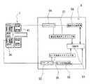
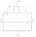
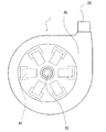
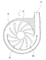
図1は、本発明の遠心式血液ポンプ装置の制御機構を含む実施例のブロック図である。図2は、本発明の遠心式血液ポンプ装置に使用される遠心式血液ポンプ装置の一例の正面図である。図3は、図2に示した遠心式血液ポンプ装置の平面図である。図4は、図2に示した実施例の遠心式血液ポンプ装置の縦断面図である。図5は、図2の遠心式血液ポンプ装置のA−A線断面図である。図6は、図2の遠心式血液ポンプ装置のA−A線断面図よりインペラを取り外した状態を示す断面図である。
本発明の遠心式血液ポンプ装置1は、液体流入ポート22と液体流出ポート23とを有するハウジング20と、内部に第1の磁性体25を備え、ハウジング20内で回転し、回転時の遠心力によって液体を送液するインペラ21を有する遠心ポンプ部2と、遠心ポンプ部2のインペラ21の第1の磁性体25を吸引するための磁石33を備えるロータ31と、ロータ31を回転させるモータ34を備えるインペラ回転トルク発生部3と、ロータ31側のハウジング20の内面もしくはインペラ21のロータ31側の面に設けられた動圧溝38を備え、ハウジング20に対して動圧溝38によりインペラ21が非接触状態にて回転する遠心式血液ポンプ装置である。遠心式血液ポンプ装置1は、インペラ21の第1の磁性体25もしくは第1の磁性体25と別に設けられた第2の磁性体28をロータ31の磁石33による吸引方向と反対方向に吸引し、インペラ21の浮上を補助するための電磁石41を備えている。
FIG. 1 is a block diagram of an embodiment including a control mechanism of a centrifugal blood pump apparatus of the present invention. FIG. 2 is a front view of an example of a centrifugal blood pump device used in the centrifugal blood pump device of the present invention. FIG. 3 is a plan view of the centrifugal blood pump apparatus shown in FIG. FIG. 4 is a longitudinal sectional view of the centrifugal blood pump apparatus of the embodiment shown in FIG. 5 is a cross-sectional view of the centrifugal blood pump device of FIG. 2 taken along line AA. 6 is a cross-sectional view showing a state where the impeller is removed from the cross-sectional view taken along the line AA of the centrifugal blood pump device of FIG.
The centrifugal
この遠心式血液ポンプ装置1は、磁気浮上ではなく、動圧溝によりインペラを実質的にハウジングに対して非接触状態にて回転させるものであり、インペラのための位置センサは不要であり、装置の小型化が可能となる。さらに、インペラ21の浮上を補助するための電磁石41を備えているので、動圧溝を備えるハウジングとインペラ間の距離を確保することができ、溶血の発生を少ないものとすることができ、かつ、電磁石はあくまでインペラの浮上を補助する程度のため消費電力も少ない。
図2ないし図6に示すように、この実施例の遠心式血液ポンプ装置1は、血液流入ポート22と血液流出ポート23を有するハウジング20と、ハウジング20内で回転し、回転時の遠心力によって血液を送液するインペラ21を有する遠心式血液ポンプ部2と、インペラ21のためのインペラ回転トルク発生部3と、インペラ21のための補助吸引制御部4とを備える。
The centrifugal
As shown in FIGS. 2 to 6, the centrifugal
インペラ21は、図4に示すように、回転時に動圧溝により発生する圧力により、ハウジング内面に接触することなく回転する。特に、このポンプ装置1では、電磁石によりインペラをロータと反対方向に吸引するため、通常の動圧溝により得られるインペラとハウジング間距離よりもさらに離間した状態にて回転する。
ハウジング20は、血液流入ポート22と血液流出ポート23とを備え、非磁性材料により形成されている。ハウジング20内には、血液流入ポート22および血液流出ポート23と連通する血液室24が形成されている。このハウジング20内には、インペラ21が収納されている。血液流入ポート22は、ハウジング20の上面の中央付近よりほぼ垂直に突出するように設けられている。血液流出ポート23は、図3および図5に示すように、ほぼ円筒状に形成されたハウジング20の側面より接線方向に突出するように設けられている。
As shown in FIG. 4, the
The
図5に示すように、ハウジング20内に形成された血液室24内には、中央に貫通口を有する円板状のインペラ21が収納されている。インペラ21は、図4に示すように、下面を形成するドーナツ板状部材(下部シュラウド)27と、上面を形成する中央が開口したドーナツ板状部材(上部シュラウド)28と、両者間に形成された複数(例えば、7つ)のベーン18を有する。そして、下部シュラウドと上部シュラウドの間には、隣り合うベーン18で仕切られた複数(7つ)の血液通路26が形成されている。血液通路26は、図5に示すように、インペラ21の中央開口と連通し、インペラ21の中央開口を始端とし、外周縁まで徐々に幅が広がるように延びている。言い換えれば、隣り合う血液通路26間にベーン18が形成されている。なお、この実施例では、それぞれの血液通路26およびそれぞれのベーン18は、等角度間隔にかつほぼ同じ形状に設けられている。
そして、図4に示すように、インペラ21には、複数(例えば、14〜24個)の第1の磁性体25(永久磁石、従動マグネット)が埋設されている。この実施例では、第1の磁性体25は、下部シュラウド27内に埋設されている。埋設された磁性体25(永久磁石)は、後述するインペラ回転トルク発生部3のロータ31に設けられた永久磁石33によりインペラ21を血液流入ポート22と反対側に吸引され、ロータとのカップリングおよび回転トルクをインペラ回転トルク発生部より伝達するために設けられている。
As shown in FIG. 5, a disc-
As shown in FIG. 4, the
また、この実施例のようにある程度の個数の磁性体25を埋設することにより、後述するロータ31との磁気的結合も十分に確保できる。磁性体25(永久磁石)の形状としては、円形であることが好ましい。あるいは、リング状のマグネットを多極(例えば、24極)に分極したもの、言い換えれば、複数の小さな磁石を磁極が交互もしくは同一となるように、かつ、リング状に並べたものでもよい。
また、インペラ21は、上部シュラウドそのものもしくは上部シュラウド内に設けられた第2の磁性体28を備える。この実施例では、上部シュラウドの全体が、磁性体28により形成されている。磁性体28は、インペラ補助吸引部の電磁石41によりインペラ21をロータ31と反対側、言い換えれば血液流入ポート22側に吸引するために設けられている。磁性体28としては、磁性ステンレス等が使用される。
Further, by embedding a certain number of
Further, the
インペラ21は、ロータ31側に吸引されるとともに電磁石41によりインペラ21をロータ31と反対方向に吸引するため、通常の動圧溝により得られるインペラとハウジング間距離よりもさらに離間した非接触状態にてハウジング20内を回転する。
インペラ回転トルク発生部3は、図4に示すように、ハウジング20内に収納されたロータ31とロータ31を回転させるためのモータ34を備える。ロータ31は、血液ポンプ部2側の面に設けられた複数の永久磁石33を備える。ロータ31の中心は、モータ34の回転軸に固定されている。永久磁石33は、インペラ21の永久磁石25の配置形態(数および配置位置)に対応するように、複数かつ等角度ごとに設けられている。
Since the
As shown in FIG. 4, the impeller rotational
また、インペラとモータ間の永久磁石のカップリングにおいて、外力によりカップリングが外れ、インペラとモータ間が脱調しても必ず両者間に吸引力が発生するように永久磁石を配置することが好ましい。このようにすることにより、カップリングが外れ、インペラとモータ間が脱調しても、両者間に吸引力が発生しているため、カップリングが容易に復帰する。
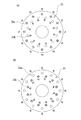
例えば、図8に示すように、インペラ21が備える第1の磁性体および第1の磁性体を吸引するためにロータ31が備える磁石はともに複数の永久磁石25、33であり、かつ複数の永久磁石25、33は、それぞれがほぼ同一円周上に同一極性となるように配置されている。さらに、インペラ21が備える永久磁石25とロータ31が備える永久磁石33は、相互に対面する円周上に配置されるとともに極性が逆の極性とすることが考えられる。つまり、インペラ21が備える永久磁石25とこれを吸引するためにロータ31が備える永久磁石33は、相互に対面する円周上に配置した永久磁石の極性が逆の極性であり、かつインペラ内及びローラにおいて円周上においては同一極性とすることである。
Further, in the coupling of the permanent magnet between the impeller and the motor, it is preferable to arrange the permanent magnet so that an attractive force is always generated between the impeller and the motor even if the coupling is released due to an external force and the impeller and the motor are stepped out. . By doing so, even if the coupling is disengaged and the impeller and the motor are stepped out, the coupling is easily restored because the suction force is generated between them.
For example, as shown in FIG. 8, the first magnetic body included in the
具体的には、図8に示すように、インペラ21に同一極性の複数の永久磁石25a(例えば、N極)を同一円周上に配置する。そして、ロータ31には、上記のインペラに設けられた永久磁石25aと対応するように、同一極性かつ永久磁石25aと極性が異なる複数の永久磁石33a(例えば、S極)を永久磁石25aが配置された円周とほぼ同じ直径となる円周上に配置する。複数の永久磁石25aは、インペラ21の中心軸に対して等角度となるように配置されることが好ましい。複数の永久磁石33aは、ロータ31の中心軸に対して等角度となるように配置されることが好ましい。また、複数の永久磁石25aの配置角度と複数の永久磁石33aの配置角度は、同じもしくは一方の配置角度に対して他方の配置角度が整数倍となっていることが好ましい。
Specifically, as shown in FIG. 8, a plurality of
さらに、図8に示すように、インペラ21は、上述した永久磁石25aが配置された円周より内側となる円周上に同一極性かつ永久磁石25aと極性の異なる永久磁石25b(例えば、S極)が複数配置されていることが好ましい。また、ロータ31には、上記のインペラに設けられた永久磁石25bと対応するように、同一極性かつ永久磁石25bと極性が異なる複数の永久磁石33b(例えば、N極)を永久磁石25bが配置された円周とほぼ同じ直径となる円周上に配置することが好ましい。複数の永久磁石25bは、インペラ21の中心軸に対して等角度となるように配置されることが好ましい。複数の永久磁石33bは、ロータ31の中心軸に対して等角度となるように配置されることが好ましい。また、複数の永久磁石25bの配置角度と複数の永久磁石33bの配置角度は、同じもしくは一方の配置角度に対して他方の配置角度が整数倍となっていることが好ましい。
Further, as shown in FIG. 8, the
インペラ補助吸引部4は、図3および図4に示すように、インペラの磁性体28を吸引するための固定された少なくとも1つの電磁石41を備えている。具体的には、ハウジング20内に収納された複数の電磁石41を有する。また、複数の電磁石41は、それぞれ等角度間隔にて設けられている。電磁石41は、鉄心とコイルからなる。電磁石41は、この実施例では、6個設けられている。電磁石41は、1〜8個が好ましい。
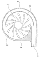
そして、この実施例の遠心式血液ポンプ装置1では、ハウジング20は、図6に示すように、インペラ21を収納するとともに血液室24を形成するハウジング内面を備え、ロータ31側のハウジング内面20aに設けられた動圧溝38を備えている。そして、インペラ21は、所定以上の回転数により回転することにより発生する動圧溝38とインペラ21間に形成される動圧軸受効果により、非接触状態にて回転する。
As shown in FIGS. 3 and 4, the impeller
In the centrifugal
動圧溝38は、図6に示すように、インペラ21の底面(ロータ側面)に対応する大きさに形成されている。この実施例のポンプ装置1では、ハウジング内面20aの中心より若干離間した円形部分の周縁(円周)上に一端を有し、渦状に(言い換えれば、湾曲して)ハウジング内面20aの外縁付近まで、幅が徐々に広がるように延びている。また、動圧溝38は複数個設けられており、それぞれの動圧溝38はほぼ同じ形状であり、かつほぼ同じ間隔に配置されている。動圧溝38は、凹部であり、深さとしては、0.005〜0.4mm程度が好適である。動圧溝としては、6〜36個程度設けることが好ましい。この実施例では、12個の動圧溝がインペラの中心軸に対して等角度に配置されている。
なお、動圧溝は、ハウジング側ではなくインペラ21のロータ側の面に設けてもよい。この場合も上述した動圧溝と同様の構成とすることが好ましい。
As shown in FIG. 6, the
The dynamic pressure groove may be provided not on the housing side but on the rotor side surface of the
このような動圧溝を有するため、インペラ回転トルク発生部3側に吸引されるが、ハウジングの動圧溝38とインペラ21の底面間(もしくはインペラの動圧溝とハウジング内面間)に形成される動圧軸受効果により、若干であるが、ハウジング内面より離れ、非接触状態にて回転し、インペラの下面とハウジング内面間に血液流路を確保するため、両者間での血液滞留およびそれに起因する血栓の発生を防止する。さらに、通常状態において、動圧溝が、インペラの下面とハウジング内面間において撹拌作用を発揮するので、両者間における部分的な血液滞留の発生を防止する。
さらに、動圧溝38は、図7に示すように、その角となる部分38aが少なくとも0.05mm以上のRを持つように面取りされていることが好ましい。このようにすることにより、溶血の発生をより少ないものとすることができる。
Since it has such a dynamic pressure groove, it is attracted to the impeller rotational
Furthermore, as shown in FIG. 7, the
また、図17および図18に示す例の遠心式血液ポンプ装置70のように、ハウジング20は、図6に示したものと同様に、インペラ21を収納するとともに血液室24を形成するハウジング内面を備え、ロータ31側のハウジング内面20aに設けられた動圧溝38を備えるとともに、電磁石41側のハウジング内面20bに設けられた第2の動圧溝71を備えている。このため、インペラ21は、所定以上の回転数により回転することにより発生する動圧溝38とインペラ21間に形成される動圧軸受効果により、非接触状態にて回転するともに、外的衝撃を受けた時また動圧溝38による動圧力が過剰となった時に、インペラのハウジング内面20b側への密着を防止する。
動圧溝71は、上述した動圧溝38と同様に、図18に示すように、インペラ21の上面(電磁石側面)に対応する大きさに形成されている。この実施例のポンプ装置70では、ハウジング内面20bの中心より若干離間した円形部分の周縁(円周)上に一端を有し、渦状に(言い換えれば、湾曲して)ハウジング内面20bの外縁付近まで、幅が徐々に広がるように延びている。また、動圧溝71は複数個設けられており、それぞれの動圧溝71はほぼ同じ形状であり、かつほぼ同じ間隔に配置されている。動圧溝71は、凹部であり、深さとしては、0.005〜0.4mm程度が好適である。動圧溝としては、6〜36個程度設けることが好ましい。この実施例では、12個の動圧溝がインペラの中心軸に対して等角度に配置されている。
Further, like the centrifugal
As shown in FIG. 18, the
なお、第2の動圧溝は、ハウジング側ではなくインペラ21の電磁石側の面に設けてもよい。この場合も上述した第2の動圧溝と同様の構成とすることが好ましい。さらに、動圧溝71は、図7に示したものものと同様に、その角となる部分が少なくとも0.05mm以上のRを持つように面取りされていることが好ましい。このようにすることにより、溶血の発生をより少ないものとすることができる。
なお、第2の動圧溝は、ハウジング側に形成されている方がより好ましい。このようにすることにより、動圧溝の形成が容易である。さらに、インペラに動圧溝を形成する場合に比べて、インペラを薄くかつインペラの重量を軽いものとすることができ、このような薄く軽いインペラは、耐外乱性能が高いものとなる。
The second dynamic pressure groove may be provided not on the housing side but on the surface of the
Note that the second dynamic pressure groove is more preferably formed on the housing side. By doing in this way, formation of a dynamic pressure groove is easy. Furthermore, the impeller can be made thinner and lighter in weight than the case where the dynamic pressure groove is formed in the impeller, and such a thin and light impeller has high disturbance resistance.
次に、本発明の他の実施例の遠心式血液ポンプ装置について説明する。
図9は、本発明の遠心式血液ポンプ装置の制御機構を含む実施例のブロック図である。図10は、本発明の遠心式血液ポンプ装置に使用される遠心式血液ポンプ装置の一例の正面図である。図11は、図10に示した実施例の遠心式血液ポンプ装置の縦断面図である。図12は、図10の遠心式血液ポンプ装置のB−B線断面図である。図13は、図10の遠心式血液ポンプ装置の底面図である。なお、図10に示した実施例の遠心式血液ポンプ装置の平面図は、図3と同じであり、図10の遠心式血液ポンプ装置のB−B線断面図よりインペラを取り外した状態の断面は、図6と同じであるのでそれらを参照する。
この実施例の遠心式血液ポンプ装置50は、液体流入ポート22と液体流出ポート23とを有するハウジング20と、内部に第1の磁性体25を備え、ハウジング20内で回転し、回転時の遠心力によって液体を送液するインペラ21を有する遠心ポンプ部2と、遠心ポンプ部2のインペラ21の第1の磁性体25を吸引するとともにインペラ21を回転させるために円周上に配置された複数のステーターコイル61を備えるインペラ回転トルク発生部3と、ステーターコイル61側のハウジング21の内面もしくはインペラ21のステーターコイル61側の面に設けられた動圧溝38を備え、ハウジング20に対して動圧溝38によりインペラ21が非接触状態にて回転する遠心式血液ポンプ装置である。遠心式血液ポンプ装置50は、インペラ21の第1の磁性体25もしくは第1の磁性体25と別に設けられた第2の磁性体28をステーターコイル61による吸引方向と反対方向に吸引し、インペラ21の浮上を補助するための電磁石41を備えている。
Next, a centrifugal blood pump device according to another embodiment of the present invention will be described.
FIG. 9 is a block diagram of an embodiment including a control mechanism of the centrifugal blood pump apparatus of the present invention. FIG. 10 is a front view of an example of a centrifugal blood pump device used in the centrifugal blood pump device of the present invention. FIG. 11 is a longitudinal sectional view of the centrifugal blood pump apparatus of the embodiment shown in FIG. 12 is a cross-sectional view of the centrifugal blood pump device of FIG. 10 taken along line BB. 13 is a bottom view of the centrifugal blood pump apparatus of FIG. The plan view of the centrifugal blood pump device of the embodiment shown in FIG. 10 is the same as that of FIG. 3, and is a cross section of the centrifugal blood pump device of FIG. Are the same as those in FIG.
The centrifugal
図11に示すように、この実施例の遠心式血液ポンプ装置50は、血液流入ポート22と血液流出ポート23を有するハウジング20と、ハウジング20内で回転し、回転時の遠心力によって血液を送液するインペラ21を有する遠心式血液ポンプ部2と、インペラ21のためのインペラ回転トルク発生部3と、インペラ21のための補助吸引制御部4とを備える。
この実施例のポンプ装置50と上述した実施例のポンプ装置1との実質的な相違は、インペラ回転トルク発生部3の機構のみである。この実施例のポンプ装置50におけるインペラ回転トルク発生部3では、いわゆるロータを備えず、直接インペラを駆動するタイプとなっている。
インペラ21は、回転時に動圧溝により発生する圧力により、ハウジング内面に接触することなく回転する。特に、このポンプ装置50では、電磁石によりインペラをステーターコイルと反対方向に吸引するため、通常の動圧溝により得られるインペラとハウジング間距離よりもさらに離間した状態にて回転する。
As shown in FIG. 11, the centrifugal
The substantial difference between the
The
ハウジング20は、血液流入ポート22と血液流出ポート23とを備え、非磁性材料により形成されている。ハウジング20内には、血液流入ポート22および血液流出ポート23と連通する血液室24が形成されている。このハウジング20内には、インペラ21が収納されている。血液流入ポート22は、ハウジング20の上面の中央付近よりほぼ垂直に突出するように設けられている。血液流出ポート23は、図3および図12に示すように、ほぼ円筒状に形成されたハウジング20の側面より接線方向に突出するように設けられている。
図11に示すように、ハウジング20内に形成された血液室24内には、中央に貫通口を有する円板状のインペラ21が収納されている。インペラ21は、図11に示すように、下面を形成するドーナツ板状部材(下部シュラウド)27と、上面を形成する中央が開口したドーナツ板状部材(上部シュラウド)28と、両者間に形成された複数(例えば、7つ)のベーン18を有する。そして、下部シュラウドと上部シュラウドの間には、隣り合うベーン18で仕切られた複数(7つ)の血液通路26が形成されている。血液通路26は、図12に示すように、インペラ21の中央開口と連通し、インペラ21の中央開口を始端とし、外周縁まで徐々に幅が広がるように延びている。言い換えれば、隣り合う血液通路26間にベーン18が形成されている。なお、この実施例では、それぞれの血液通路26およびそれぞれのベーン18は、等角度間隔にかつほぼ同じ形状に設けられている。
The
As shown in FIG. 11, a disc-shaped
そして、図12に示すように、インペラ21には、複数(例えば、6〜12個)の第1の磁性体25(永久磁石、従動マグネット)が埋設されている。この実施例では、第1の磁性体25は、下部シュラウド27内に埋設されている。埋設された磁性体25(永久磁石)は、後述するインペラ回転トルク発生部3のステーターコイル61によりインペラ21を血液流入ポート22と反対側に吸引され、ステーターコイル61の作動とカップリングするとともに回転トルクを伝達するために設けられている。
また、この実施例のようにある程度の個数の磁性体25を埋設することにより、後述するステーターコイル61との磁気的結合も十分に確保できる。磁性体25(永久磁石)の形状としては、略台形状であることが好ましい。磁性体25は、リング状、板状のいずれでもよい。また、磁性体25の数および配置形態は、ステーターコイルの数および配置形態に対応していることが好ましい。複数の磁性体25は、磁極が交互に異なるように、かつ、インペラの中心軸に対してほぼ等角度となるように円周上に配置されている。
And as shown in FIG. 12, the
Further, by embedding a certain number of
また、インペラ21は、上部シュラウドそのものもしくは上部シュラウド内に設けられた第2の磁性体28を備える。この実施例では、上部シュラウドの全体が、磁性体28により形成されている。磁性体28は、インペラ補助吸引部の電磁石41によりインペラ21をステーターコイル61と反対側、言い換えれば血液流入ポート22側に吸引するために設けられている。磁性体28としては、磁性ステンレス等が使用される。
インペラ21は、ステーターコイル側に吸引されるとともに電磁石によりインペラをステーターコイルと反対方向に吸引するため、通常の動圧溝により得られるインペラとハウジング間距離よりもさらに離間した非接触状態にてハウジング20内を回転する。
Further, the
Since the
インペラ回転トルク発生部3は、図11および図13に示すように、ハウジング20内に収納された複数のステーターコイル61を備える。ステーターコイル61は、円周上にほぼその円周の中心軸に対して等角度となるように複数配置されている。具体的には、6個のステーターコイルが用いられている。また、ステーターコイルとしては、多層巻きのステーターコイルが用いられる。各ステーターコイル61に流れる電流の方向を切り換えることにより、回転磁界が発生し、この回転磁界により、インペラは吸引されるとともに回転する。
インペラ補助吸引部4については、上述した実施例の遠心式血液ポンプ装置1と同じであるので、上述した説明を参照するものとする。
As shown in FIGS. 11 and 13, the impeller rotational
The impeller
また、この実施例の遠心式血液ポンプ装置50においても、ハウジング20は、図6に示すように、インペラ21を収納するとともに血液室24を形成するハウジング内面を備え、ステーターコイル61側のハウジング内面20aに設けられた動圧溝38を備えている。そして、インペラ21は、所定以上の回転数により回転することにより発生する動圧溝38とインペラ21間に形成される動圧軸受効果により、非接触状態にて回転する。動圧溝38については、上述した実施例の遠心式血液ポンプ装置1と同じであるので、上述した説明を参照するものとする。また、動圧溝は、ハウジング側ではなくインペラ21のステーターコイル側の面に設けてもよい。この場合も上述した動圧溝と同様の構成とすることが好ましい。さらに、動圧溝38は、図7に示すように、その角となる部分38aが少なくとも0.05mm以上のRを持つように面取りされていることが好ましい。このようにすることにより、溶血の発生をより少ないものとすることができる。
Also in the centrifugal
さらに、この実施例のタイプの遠心式血液ポンプ装置50においても、図17および図18に示す例の遠心式血液ポンプ装置70のように、ハウジング20は、電磁石41側のハウジング内面20bに設けられた第2の動圧溝を備えていてもよい。第2の動圧溝については、上述した実施例の遠心式血液ポンプ装置70と同じであるので、上述した説明を参照するものとする。また、第2の動圧溝は、ハウジング側ではなくインペラ21の電磁石側の面に設けてもよい。この場合も上述した動圧溝と同様の構成とすることが好ましい。さらに、第2の動圧溝は、図7に示したものと同様に、その角となる部分が少なくとも0.05mm以上のRを持つように面取りされていることが好ましい。このようにすることにより、溶血の発生をより少ないものとすることができる。
Further, also in the centrifugal
また、上述した実施例の遠心式血液ポンプ装置には、制御機構6を設けることが好ましい。
遠心式血液ポンプ装置1に用いられる制御機構6について、図1および図9を用いて説明する。
図1に示す実施例の遠心式血液ポンプ装置1の制御機構6は、インペラ回転トルク発生部3のモータ34のためのパワーアンプ52、モータ制御回路53、モータ電流モニタリング部55、電磁石41のためのパワーアンプ54、電磁石制御回路56、電磁石電流モニタリング部57、制御部51を備える。なお、モータ電流モニタリング機能は、制御部51が備えるものとしてもよい。
図9に示す実施例の遠心式血液ポンプ装置50の制御機構6は、インペラ回転トルク発生部3のステーターコイル61のためのパワーアンプ62、ステーターコイル制御回路63、ステーターコイル電流モニタリング部64、電磁石41のためのパワーアンプ54、電磁石制御回路56、電磁石電流モニタリング部57、制御部51を備える。なお、ステーターコイル電流モニタリング機能は、制御部51が備えるものとしてもよい。
Moreover, it is preferable to provide the
A
The
The
そして、制御機構6は、インペラ回転トルク発生部(具体的には、モータまたはステーターコイル)および電磁石41を制御する。特に、制御機構6は、インペラ回転トルク発生部の回転数(言い換えれば、インペラ回転トルク発生部によって発生される回転速度)に応じて電磁石41によるインペラの吸引力を変化させる機能を備えていることが好ましい。また、制御機構6は、インペラ回転トルク発生部の回転数(言い換えれば、インペラ回転トルク発生部によって発生される回転速度)に応じて電磁石41によるインペラ21の吸引力を変化させることにより、インペラとハウジング間の距離をほぼ一定に保持する機能を備えていることが好ましく、この距離は50〜150μmが好ましい。具体的には、遠心式血液ポンプ装置1、50は、インペラ回転トルク発生部電流モニタリング機能を備え、制御機構6は、インペラ回転トルク発生部電流モニタリング機能により検知されるモータ電流値を用いて前記電磁石を制御するものである。
インペラ回転トルク発生部(具体的には、モータまたはステーターコイル)の回転数に応じて電磁石によるインペラの吸引力を変化させるのは、動圧溝によって負荷容量が発生するためである。負荷容量とは軸受の用語であり力の次元を持つ。電磁石の吸引力と同じ方向に作用する。この負荷容量は、動圧溝の形状が単純な段付き溝の場合、2次元の理論解析(動圧溝の断面形状のみを考慮し、その断面と直交する長さ方向は断面の幅に対して十分長いとして行う解析)によると、流体の粘度と回転数に比例する。
Then, the
The reason why the attraction force of the impeller by the electromagnet is changed in accordance with the rotational speed of the impeller rotational torque generating unit (specifically, the motor or the stator coil) is that load capacity is generated by the dynamic pressure groove. Load capacity is a term for bearings and has a dimension of force. Acts in the same direction as the attractive force of the electromagnet. In the case of a stepped groove with a simple dynamic pressure groove shape, this load capacity is calculated based on a two-dimensional theoretical analysis (considering only the cross-sectional shape of the dynamic pressure groove, the length direction perpendicular to the cross section is According to the analysis performed as long as possible, it is proportional to the viscosity and the rotational speed of the fluid.
上述した実施例の遠心式血液ポンプ装置1、50では、1)インペラとモータ間にはカップリング力(ポンプ装置1では永久磁石により、ポンプ装置50ではステーターコイルによる)が働き、2)インペラと電磁石間には電磁石による吸引力と動圧溝による負荷容量が働く。
1)の力と2)の力が釣り合う位置にて、インペラはハウジング内にて浮上し回転する。インペラとハウジング間の距離は、溶血の発生の十分に少ない距離とすることが好ましいが、距離を多くとるためには、電磁石電流を高くしなければならない。そこで、インペラとハウジング間の距離は、動圧溝のみによる得られる距離より大きくかつ許容できる小さな値とすることが消費電力の点より望ましい。そこで、インペラとハウジング間の距離が許容できる小さな値において釣り合うように制御することが必要となる。つまり、1)の力が一定の場合には、2)の力を回転数が変わっても一定にする必要がある。2)の力は、電磁石の吸引力と負荷容量の和であるから、回転数によって負荷容量が変化した場合、電磁石の吸引力を変えることで和を一定にすれば、目的とする浮上位置を確保することができる。具体的には、2)の力における負荷容量はインペラの回転数により増加するので、電磁石の吸引力(言い換えれば、電磁石電流)を低下させても、目的とする浮上位置を確保することができ、消費電力が少ないものとなる。
In the centrifugal
At a position where the force 1) and the force 2) are balanced, the impeller floats and rotates in the housing. The distance between the impeller and the housing is preferably a sufficiently small distance that does not cause hemolysis, but in order to increase the distance, the electromagnet current must be increased. Therefore, it is desirable from the viewpoint of power consumption that the distance between the impeller and the housing is larger than the distance obtained by only the dynamic pressure groove and has an allowable small value. Therefore, it is necessary to control so that the distance between the impeller and the housing is balanced at a small allowable value. That is, when the force of 1) is constant, the force of 2) needs to be constant even if the rotational speed changes. The force of 2) is the sum of the attractive force of the electromagnet and the load capacity. If the load capacity changes depending on the number of rotations, the target floating position can be determined by making the sum constant by changing the attractive force of the electromagnet. Can be secured. Specifically, since the load capacity at the force of 2) increases with the impeller rotation speed, the target floating position can be secured even if the attraction force of the electromagnet (in other words, the electromagnet current) is reduced. The power consumption is low.
次に、前述した、動圧溝の形状が単純な段付き溝の場合の2次元の理論解析結果を記す。
図15の形状(溝の断面方向の長さはLとする)の動圧溝の場合を考えると、圧力pは、
領域1(0<x<Bo)の場合: p=(Pm/Bo)x
領域2(Bo<x<B)の場合: p=[Pm/(B−Bo)](B−x)
となる(pのy方向の変化は十分小さく、無視できる)。ここで、
Pm=6μU(h1−h2)/[h1 3/Bo+h2 3/(B−Bo)]
である。式中のμ、Uはそれぞれ、流体の粘度、インペラの半径方向速度(回転数に比例)である。
したがって、負荷容量Wは、
W=L∫0 B pdx
=LBPm/2
である。このWをμULB2で除して無次元化したWd−lessは、
Wd−less=Wh2 2/(μULB2)
=3s(1−s)(a−1)/[a3(1−s)+s]
である。ここで、a、sは、
a=h1/h2 s=Bo/B
である。すると、a、sについてのWd−lessの変化は、図16のようになり、所望のh1、h2にするときに最大の負荷容量が得られる(効率の良い)s(BoとBの比)が存在することがわかる。したがって動圧溝の形状パラメータ:
h1−h2
B、Bo、L
を適値に設定することで、十分な負荷容量を得ることができ、結果として電磁石の吸引力を抑えた省電力の血液ポンプを提供できる。
Next, the two-dimensional theoretical analysis result in the case where the above-described dynamic pressure groove has a simple stepped groove will be described.
Considering the case of the dynamic pressure groove having the shape of FIG. 15 (the length in the cross-sectional direction of the groove is L), the pressure p is
For region 1 (0 <x <Bo): p = (Pm / Bo) x
For region 2 (Bo <x <B): p = [Pm / (B−Bo)] (B−x)
(The change in the y direction of p is sufficiently small and can be ignored). here,
Pm = 6 μU (h 1 −h 2 ) / [h 1 3 / Bo + h 2 3 / (B−Bo)]
It is. In the equation, μ and U are respectively the viscosity of the fluid and the radial speed of the impeller (proportional to the number of rotations).
Therefore, the load capacity W is
W = L∫ 0 B pdx
= LBPm / 2
It is. Wd-less, which is made dimensionless by dividing this W by μULB 2 ,
Wd-less = Wh 2 2 / (μULB 2 )
= 3s (1-s) ( a-1) / [a 3 (1-s) + s]
It is. Where a and s are
a = h 1 / h 2 s = Bo / B
It is. Then, the change of Wd-less with respect to a and s is as shown in FIG. 16, and the maximum load capacity can be obtained (highly efficient) s (Bo and B) when desired h 1 and h 2 are set. Ratio) exists. Therefore, the shape parameter of the dynamic pressure groove:
h 1 -h 2
B, Bo, L
By setting to an appropriate value, a sufficient load capacity can be obtained, and as a result, a power-saving blood pump that suppresses the attractive force of the electromagnet can be provided.
また、制御機構6は、電磁石41によりインペラ21を所定値以上の力にて吸引した状態にてインペラ回転トルク発生部による回転を開始させる回転開始状態制御機能を備えていることが好ましい。さらに、制御機構6は、電磁石41によりインペラ21を所定値以上の吸引力にて吸引した状態にてインペラ回転トルク発生部3による回転を開始させる回転開始状態制御機能と、インペラ回転トルク発生部3の回転開始後、吸引力を前記所定値より低下させるインペラ回転トルク発生部回転後制御機能を備えていることが好ましい。このインペラ回転トルク発生部回転後制御機能は、インペラ回転トルク発生部3の回転数に応じて電磁石によるインペラの吸引力を変化させるものであることが好ましい。
The
さらに、制御機構6は、インペラ21とインペラ回転トルク発生部3とのカップリングが外れる、いわゆる脱調状態を検出する機能を備えることが好ましい。さらに、脱調検出後に作動する再カップリング機能を備えることが好ましい。
具体的には、制御部51は、モータ電流モニタリング部55からの出力を用いて脱調状態であることを判断する脱調検出機能と、脱調検出後に作動する再カップリング機能を備えている。再カップリング機能としては、例えば、脱調検出後に、モータおよび電磁石41を一旦停止させた後、電磁石41のみを作動させて、続いてインペラ回転トルク発生部による回転を開始するように行うことが好ましい。なお、脱調の判断は、最低インペラ回転トルク発生部電流値を制御部が記憶しその値より低い場合に脱調と判断することが考えられる。また、脱調の判断は、インペラ回転トルク発生部3による回転数に対してインペラ回転トルク発生部電流が所定値より小さいことにより判断するものであってもよい。具体的には、所定のモータ回転数(例えば、1000rpm)におけるモータ電流値(例えば、0.12A)を記憶しており、実際のモータ回転状態が、上記の回転数より大きいにもかかわらずモータ電流が上記のモータ電流値より小さい場合に、インペラとロータのカップリング離脱と判断する。
Furthermore, it is preferable that the
Specifically, the
次に、この実施例の遠心式血液ポンプ装置1の作用を図14に示すフローチャートを用いて説明する。
遠心式血液ポンプ装置1がスタートすると、最初に電磁石が作動し、インペラ21をインペラ回転トルク発生部3(具体的には、ロータまたはステーターコイル)と反対側に吸引力を与える。そして、電磁石電流値が所定値に到達した後に、インペラ回転トルク発生部3により回転、具体的にはモータの回転が開始され、インペラ21は回転する。電磁石電流の印加方法は、矩形波形電流のデューティー比を変えることで電磁石41による吸引力を調整する方法もある。そして、インペラ回転トルク発生部3による回転数に対応して電磁石電流の制御が行われる。具体的には、インペラ21の回転数の増加による負荷容量の増加に起因するインペラ21のハウジング内面からの離間分、電磁石電流を低下させて、電磁石41によるインペラ21の吸引力を低下させる。またこの、電磁石電流制御と並行して、常時モータ電流が所定範囲内であるかどうか検知しており、所定値範囲外であると脱調と判断し、モータ34および電磁石41を一旦停止させる。そして、電磁石のみを作動させて、通常の作動に移行する。
Next, the operation of the centrifugal
When the centrifugal
1 遠心式血液ポンプ装置
2 遠心ポンプ部
3 インペラ回転トルク発生部
20 ハウジング
21 インペラ
25 第1の磁性体
31 ロータ
33 磁石
34 モータ
38 動圧溝
41 電磁石
DESCRIPTION OF
Claims (8)
前記遠心式血液ポンプ装置は、前記インペラのための位置センサを持たないものであり、かつ、前記インペラの前記第1の磁性体もしくは該第1の磁性体と別に設けられた第2の磁性体を前記ロータの磁石による吸引方向と反対方向に吸引し、前記インペラの浮上を補助するための電磁石と、前記インペラ回転トルク発生部および前記電磁石を制御する制御機構を備え、前記制御機構は、インペラ回転トルク発生部電流モニタリング機能を備え、該モニタリング機能により検知される電流値を用いて前記電磁石を制御するものであり、さらに、前記制御機構は、前記電磁石により前記インペラを所定値以上の力にて吸引した状態にてインペラ回転トルク発生部による回転を開始させる回転開始状態制御機能と、前記インペラ回転トルク発生部による回転開始後、吸引力を前記所定値より低下させるインペラ回転トルク発生部回転後制御機能とを備えるものであることを特徴とする遠心式血液ポンプ装置。 A housing having a liquid inflow port and a liquid outflow port; a centrifugal pump unit having an impeller that includes a first magnetic body therein, rotates in the housing, and sends liquid by centrifugal force during rotation; A rotor including a magnet for attracting the first magnetic body of the impeller of the centrifugal pump unit; an impeller rotational torque generating unit including a motor for rotating the rotor; and an inner surface of the housing on the rotor side or the rotor of the impeller A centrifugal blood pump device comprising a dynamic pressure groove provided on a side surface, wherein the impeller rotates in a non-contact state by the dynamic pressure groove with respect to the housing,
The centrifugal blood pump device does not have a position sensor for the impeller, and the first magnetic body of the impeller or a second magnetic body provided separately from the first magnetic body And a control mechanism for controlling the impeller rotation torque generator and the electromagnet, the control mechanism comprising: an impeller that attracts the rotor in a direction opposite to the suction direction by the magnet of the rotor ; A rotational torque generator current monitoring function is provided, and the electromagnet is controlled using a current value detected by the monitoring function. Further, the control mechanism causes the impeller to force the impeller to a force greater than a predetermined value. A rotation start state control function for starting rotation by the impeller rotational torque generating unit in a state where the impeller is rotated and the impeller rotational torque generating unit Rotating after the start by centrifugal blood pump apparatus, characterized in that the suction force is intended and a impeller rotation torque generating section rotating after the control function to lower than the predetermined value.
前記遠心式血液ポンプ装置は、前記インペラのための位置センサを持たないものであり、かつ、前記インペラの前記第1の磁性体もしくは該第1の磁性体と別に設けられた第2の磁性体を前記ステーターコイルによる吸引方向と反対方向に吸引し、前記インペラの浮上を補助するための電磁石と、前記インペラ回転トルク発生部および前記電磁石を制御する制御機構を備え、前記制御機構は、インペラ回転トルク発生部電流モニタリング機能を備え、該モニタリング機能により検知される電流値を用いて前記電磁石を制御するものであり、さらに、前記制御機構は、前記電磁石により前記インペラを所定値以上の力にて吸引した状態にてインペラ回転トルク発生部による回転を開始させる回転開始状態制御機能と、前記インペラ回転トルク発生部による回転開始後、吸引力を前記所定値より低下させるインペラ回転トルク発生部回転後制御機能とを備えるものであることを特徴とする遠心式血液ポンプ装置。 A housing having a liquid inflow port and a liquid outflow port; a centrifugal pump unit having an impeller that includes a first magnetic body therein, rotates in the housing, and sends liquid by centrifugal force during rotation; An impeller rotational torque generator including a plurality of stator coils arranged on the circumference for attracting the first magnetic body of the impeller of the centrifugal pump unit and rotating the impeller; and an inner surface of the housing on the stator coil side Or a centrifugal blood pump device comprising a dynamic pressure groove provided on the surface of the impeller on the side of the stator coil, wherein the impeller rotates in a non-contact state by the dynamic pressure groove with respect to the housing,
The centrifugal blood pump device does not have a position sensor for the impeller, and the first magnetic body of the impeller or a second magnetic body provided separately from the first magnetic body And a control mechanism for controlling the impeller rotation torque generator and the electromagnet, and the control mechanism is configured to rotate the impeller. A torque generator current monitoring function is provided, and the electromagnet is controlled using a current value detected by the monitoring function. Further, the control mechanism is configured to control the impeller with a force of a predetermined value or more by the electromagnet. A rotation start state control function for starting rotation by the impeller rotation torque generation unit in the sucked state, and the impeller rotation torque generation After the start of rotation by the parts, centrifugal blood pump apparatus characterized in that comprises an impeller rotational torque generating section rotating after the control function of the suction force is lower than the predetermined value.
Priority Applications (1)
| Application Number | Priority Date | Filing Date | Title |
|---|---|---|---|
| JP2003417932A JP4456857B2 (en) | 2002-12-17 | 2003-12-16 | Centrifugal blood pump device |
Applications Claiming Priority (2)
| Application Number | Priority Date | Filing Date | Title |
|---|---|---|---|
| JP2002365039 | 2002-12-17 | ||
| JP2003417932A JP4456857B2 (en) | 2002-12-17 | 2003-12-16 | Centrifugal blood pump device |
Publications (3)
| Publication Number | Publication Date |
|---|---|
| JP2004209240A JP2004209240A (en) | 2004-07-29 |
| JP2004209240A5 JP2004209240A5 (en) | 2007-01-25 |
| JP4456857B2 true JP4456857B2 (en) | 2010-04-28 |
Family
ID=32828712
Family Applications (1)
| Application Number | Title | Priority Date | Filing Date |
|---|---|---|---|
| JP2003417932A Expired - Fee Related JP4456857B2 (en) | 2002-12-17 | 2003-12-16 | Centrifugal blood pump device |
Country Status (1)
| Country | Link |
|---|---|
| JP (1) | JP4456857B2 (en) |
Families Citing this family (29)
| Publication number | Priority date | Publication date | Assignee | Title |
|---|---|---|---|---|
| JP4787726B2 (en) | 2006-11-28 | 2011-10-05 | テルモ株式会社 | Sensorless magnetic bearing blood pump device |
| WO2009157408A1 (en) | 2008-06-23 | 2009-12-30 | テルモ株式会社 | Blood pump apparatus |
| EP2372160B1 (en) | 2008-12-08 | 2014-07-30 | Thoratec Corporation | Centrifugal pump device |
| JP5378010B2 (en) | 2009-03-05 | 2013-12-25 | ソラテック コーポレーション | Centrifugal pump device |
| CN102341600B (en) | 2009-03-06 | 2014-12-10 | 胸腔科技有限公司 | Centrifugal pump device |
| EP3490122B1 (en) | 2009-07-29 | 2021-01-27 | Thoratec Corporation | Rotation drive device and centrifugal pump device |
| JP5443197B2 (en) | 2010-02-16 | 2014-03-19 | ソラテック コーポレーション | Centrifugal pump device |
| EP2554191B1 (en) | 2010-03-26 | 2019-05-08 | Thoratec Corporation | Centrifugal blood pump device |
| JP5681403B2 (en) | 2010-07-12 | 2015-03-11 | ソーラテック コーポレイション | Centrifugal pump device |
| JP5577506B2 (en) | 2010-09-14 | 2014-08-27 | ソーラテック コーポレイション | Centrifugal pump device |
| WO2012132850A1 (en) | 2011-03-28 | 2012-10-04 | Ntn株式会社 | Rotation and drive device and centrifugal pump device using same |
| JP6083929B2 (en) | 2012-01-18 | 2017-02-22 | ソーラテック コーポレイション | Centrifugal pump device |
| US9371826B2 (en) | 2013-01-24 | 2016-06-21 | Thoratec Corporation | Impeller position compensation using field oriented control |
| US9556873B2 (en) | 2013-02-27 | 2017-01-31 | Tc1 Llc | Startup sequence for centrifugal pump with levitated impeller |
| US9713663B2 (en) | 2013-04-30 | 2017-07-25 | Tc1 Llc | Cardiac pump with speed adapted for ventricle unloading |
| US10052420B2 (en) | 2013-04-30 | 2018-08-21 | Tc1 Llc | Heart beat identification and pump speed synchronization |
| ES2856762T3 (en) * | 2014-05-13 | 2021-09-28 | Abiomed Inc | Blood pump housing component |
| US9623161B2 (en) | 2014-08-26 | 2017-04-18 | Tc1 Llc | Blood pump and method of suction detection |
| WO2016130846A1 (en) | 2015-02-11 | 2016-08-18 | Thoratec Corporation | Heart beat identification and pump speed synchronization |
| WO2016130944A1 (en) | 2015-02-12 | 2016-08-18 | Thoratec Corporation | System and method for controlling the position of a levitated rotor |
| US10371152B2 (en) | 2015-02-12 | 2019-08-06 | Tc1 Llc | Alternating pump gaps |
| EP3626277A1 (en) | 2015-02-13 | 2020-03-25 | Tc1 Llc | Impeller suspension mechanism for heart pump |
| US10117983B2 (en) | 2015-11-16 | 2018-11-06 | Tc1 Llc | Pressure/flow characteristic modification of a centrifugal pump in a ventricular assist device |
| AU2018280236A1 (en) | 2017-06-07 | 2020-01-16 | Shifamed Holdings, Llc | Intravascular fluid movement devices, systems, and methods of use |
| JP7319266B2 (en) | 2017-11-13 | 2023-08-01 | シファメド・ホールディングス・エルエルシー | Intravascular fluid transfer devices, systems and methods of use |
| CN112004563A (en) | 2018-02-01 | 2020-11-27 | 施菲姆德控股有限责任公司 | Intravascular blood pump and methods of use and manufacture |
| EP3996797A4 (en) | 2019-07-12 | 2023-08-02 | Shifamed Holdings, LLC | Intravascular blood pumps and methods of manufacture and use |
| US11654275B2 (en) | 2019-07-22 | 2023-05-23 | Shifamed Holdings, Llc | Intravascular blood pumps with struts and methods of use and manufacture |
| US11724089B2 (en) | 2019-09-25 | 2023-08-15 | Shifamed Holdings, Llc | Intravascular blood pump systems and methods of use and control thereof |
-
2003
- 2003-12-16 JP JP2003417932A patent/JP4456857B2/en not_active Expired - Fee Related
Also Published As
| Publication number | Publication date |
|---|---|
| JP2004209240A (en) | 2004-07-29 |
Similar Documents
| Publication | Publication Date | Title |
|---|---|---|
| JP4456857B2 (en) | Centrifugal blood pump device | |
| JP4472610B2 (en) | Centrifugal blood pump device | |
| US7470246B2 (en) | Centrifugal blood pump apparatus | |
| JP4472612B2 (en) | Centrifugal blood pump device | |
| JP3996775B2 (en) | Centrifugal liquid pump device | |
| US7128538B2 (en) | Centrifugal fluid pump apparatus | |
| JP4787726B2 (en) | Sensorless magnetic bearing blood pump device | |
| JP4767488B2 (en) | Magnetic levitation pump | |
| JP4759261B2 (en) | Centrifugal blood pump device | |
| JP5656835B2 (en) | Rotation drive device and centrifugal pump device using the same | |
| JP5572832B2 (en) | Centrifugal blood pump device | |
| JP4340178B2 (en) | Centrifugal blood pump device | |
| JP4340183B2 (en) | Centrifugal blood pump device | |
| JP2010133381A (en) | Centrifugal pump device | |
| WO2015098709A1 (en) | Centrifugal pump system | |
| JP4472611B2 (en) | Centrifugal blood pump device | |
| JP2005118237A (en) | Centrifugal blood pump having dynamic pressure bearing axially or diametrically | |
| JP2010041742A (en) | Axially levitated rotating motor, and turbo-type pump using axially levitated rotating motor | |
| JP4685227B2 (en) | Magnetic levitation pump | |
| JP4340182B2 (en) | Blood pump device | |
| JP4004401B2 (en) | Liquid pump device | |
| JP2010136862A (en) | Centrifugal type pump apparatus |
Legal Events
| Date | Code | Title | Description |
|---|---|---|---|
| A521 | Request for written amendment filed |
Free format text: JAPANESE INTERMEDIATE CODE: A523 Effective date: 20061206 |
|
| A621 | Written request for application examination |
Free format text: JAPANESE INTERMEDIATE CODE: A621 Effective date: 20061206 |
|
| A131 | Notification of reasons for refusal |
Free format text: JAPANESE INTERMEDIATE CODE: A131 Effective date: 20091027 |
|
| A521 | Request for written amendment filed |
Free format text: JAPANESE INTERMEDIATE CODE: A523 Effective date: 20091225 |
|
| TRDD | Decision of grant or rejection written | ||
| A01 | Written decision to grant a patent or to grant a registration (utility model) |
Free format text: JAPANESE INTERMEDIATE CODE: A01 Effective date: 20100126 |
|
| A01 | Written decision to grant a patent or to grant a registration (utility model) |
Free format text: JAPANESE INTERMEDIATE CODE: A01 |
|
| A61 | First payment of annual fees (during grant procedure) |
Free format text: JAPANESE INTERMEDIATE CODE: A61 Effective date: 20100208 |
|
| FPAY | Renewal fee payment (event date is renewal date of database) |
Free format text: PAYMENT UNTIL: 20130212 Year of fee payment: 3 |
|
| R150 | Certificate of patent or registration of utility model |
Ref document number: 4456857 Country of ref document: JP Free format text: JAPANESE INTERMEDIATE CODE: R150 Free format text: JAPANESE INTERMEDIATE CODE: R150 |
|
| FPAY | Renewal fee payment (event date is renewal date of database) |
Free format text: PAYMENT UNTIL: 20140212 Year of fee payment: 4 |
|
| R250 | Receipt of annual fees |
Free format text: JAPANESE INTERMEDIATE CODE: R250 |
|
| S111 | Request for change of ownership or part of ownership |
Free format text: JAPANESE INTERMEDIATE CODE: R313117 |
|
| R350 | Written notification of registration of transfer |
Free format text: JAPANESE INTERMEDIATE CODE: R350 |
|
| S111 | Request for change of ownership or part of ownership |
Free format text: JAPANESE INTERMEDIATE CODE: R313113 |
|
| R350 | Written notification of registration of transfer |
Free format text: JAPANESE INTERMEDIATE CODE: R350 |
|
| R250 | Receipt of annual fees |
Free format text: JAPANESE INTERMEDIATE CODE: R250 |
|
| R250 | Receipt of annual fees |
Free format text: JAPANESE INTERMEDIATE CODE: R250 |
|
| R250 | Receipt of annual fees |
Free format text: JAPANESE INTERMEDIATE CODE: R250 |
|
| R250 | Receipt of annual fees |
Free format text: JAPANESE INTERMEDIATE CODE: R250 |
|
| R250 | Receipt of annual fees |
Free format text: JAPANESE INTERMEDIATE CODE: R250 |
|
| LAPS | Cancellation because of no payment of annual fees |