EP3600477B1 - Communication architecture for heart treatment systems - Google Patents
Communication architecture for heart treatment systems Download PDFInfo
- Publication number
- EP3600477B1 EP3600477B1 EP18718313.2A EP18718313A EP3600477B1 EP 3600477 B1 EP3600477 B1 EP 3600477B1 EP 18718313 A EP18718313 A EP 18718313A EP 3600477 B1 EP3600477 B1 EP 3600477B1
- Authority
- EP
- European Patent Office
- Prior art keywords
- heart
- pump
- electrical
- frequency
- implantable
- Prior art date
- Legal status (The legal status is an assumption and is not a legal conclusion. Google has not performed a legal analysis and makes no representation as to the accuracy of the status listed.)
- Active
Links
- 238000004891 communication Methods 0.000 title description 41
- 230000033764 rhythmic process Effects 0.000 claims description 138
- 230000000747 cardiac effect Effects 0.000 claims description 100
- 239000008280 blood Substances 0.000 claims description 96
- 210000004369 blood Anatomy 0.000 claims description 96
- 230000002159 abnormal effect Effects 0.000 claims description 44
- 238000005086 pumping Methods 0.000 claims description 41
- 230000000638 stimulation Effects 0.000 claims description 28
- 230000004044 response Effects 0.000 claims description 7
- 230000008878 coupling Effects 0.000 claims description 2
- 238000010168 coupling process Methods 0.000 claims description 2
- 238000005859 coupling reaction Methods 0.000 claims description 2
- 238000000034 method Methods 0.000 description 22
- 230000000694 effects Effects 0.000 description 13
- 206010019280 Heart failures Diseases 0.000 description 6
- 208000024172 Cardiovascular disease Diseases 0.000 description 5
- 238000009125 cardiac resynchronization therapy Methods 0.000 description 5
- 239000007943 implant Substances 0.000 description 5
- 208000019622 heart disease Diseases 0.000 description 4
- 230000003287 optical effect Effects 0.000 description 4
- 230000002861 ventricular Effects 0.000 description 4
- 230000009286 beneficial effect Effects 0.000 description 3
- 206010061592 cardiac fibrillation Diseases 0.000 description 3
- 230000034994 death Effects 0.000 description 3
- 231100000517 death Toxicity 0.000 description 3
- 238000001514 detection method Methods 0.000 description 3
- 230000002600 fibrillogenic effect Effects 0.000 description 3
- 238000002560 therapeutic procedure Methods 0.000 description 3
- 208000019269 advanced heart failure Diseases 0.000 description 2
- 210000001367 artery Anatomy 0.000 description 2
- 230000017531 blood circulation Effects 0.000 description 2
- 210000000748 cardiovascular system Anatomy 0.000 description 2
- 230000007423 decrease Effects 0.000 description 2
- 230000006870 function Effects 0.000 description 2
- 210000005240 left ventricle Anatomy 0.000 description 2
- 238000012986 modification Methods 0.000 description 2
- 230000004048 modification Effects 0.000 description 2
- 238000012545 processing Methods 0.000 description 2
- 230000000541 pulsatile effect Effects 0.000 description 2
- 230000000284 resting effect Effects 0.000 description 2
- 210000005241 right ventricle Anatomy 0.000 description 2
- 230000001360 synchronised effect Effects 0.000 description 2
- 206010003130 Arrhythmia supraventricular Diseases 0.000 description 1
- 208000001647 Renal Insufficiency Diseases 0.000 description 1
- 208000004756 Respiratory Insufficiency Diseases 0.000 description 1
- 206010047281 Ventricular arrhythmia Diseases 0.000 description 1
- 230000009471 action Effects 0.000 description 1
- 230000002411 adverse Effects 0.000 description 1
- 210000000709 aorta Anatomy 0.000 description 1
- 210000002376 aorta thoracic Anatomy 0.000 description 1
- 206010003119 arrhythmia Diseases 0.000 description 1
- 230000006793 arrhythmia Effects 0.000 description 1
- 210000005242 cardiac chamber Anatomy 0.000 description 1
- 230000007797 corrosion Effects 0.000 description 1
- 238000005260 corrosion Methods 0.000 description 1
- 230000003247 decreasing effect Effects 0.000 description 1
- 230000001419 dependent effect Effects 0.000 description 1
- 201000010099 disease Diseases 0.000 description 1
- 208000037265 diseases, disorders, signs and symptoms Diseases 0.000 description 1
- 238000013399 early diagnosis Methods 0.000 description 1
- 230000002526 effect on cardiovascular system Effects 0.000 description 1
- 230000005684 electric field Effects 0.000 description 1
- 210000001174 endocardium Anatomy 0.000 description 1
- 238000005516 engineering process Methods 0.000 description 1
- 239000012530 fluid Substances 0.000 description 1
- 238000002513 implantation Methods 0.000 description 1
- 208000015181 infectious disease Diseases 0.000 description 1
- 238000002955 isolation Methods 0.000 description 1
- 201000006370 kidney failure Diseases 0.000 description 1
- 210000005246 left atrium Anatomy 0.000 description 1
- 230000007774 longterm Effects 0.000 description 1
- 238000012544 monitoring process Methods 0.000 description 1
- 230000037361 pathway Effects 0.000 description 1
- 230000002093 peripheral effect Effects 0.000 description 1
- 201000004193 respiratory failure Diseases 0.000 description 1
- 210000005245 right atrium Anatomy 0.000 description 1
- 230000011664 signaling Effects 0.000 description 1
- 230000002792 vascular Effects 0.000 description 1
Images


Classifications
-
- A—HUMAN NECESSITIES
- A61—MEDICAL OR VETERINARY SCIENCE; HYGIENE
- A61N—ELECTROTHERAPY; MAGNETOTHERAPY; RADIATION THERAPY; ULTRASOUND THERAPY
- A61N1/00—Electrotherapy; Circuits therefor
- A61N1/18—Applying electric currents by contact electrodes
- A61N1/32—Applying electric currents by contact electrodes alternating or intermittent currents
- A61N1/36—Applying electric currents by contact electrodes alternating or intermittent currents for stimulation
- A61N1/372—Arrangements in connection with the implantation of stimulators
- A61N1/37211—Means for communicating with stimulators
- A61N1/37252—Details of algorithms or data aspects of communication system, e.g. handshaking, transmitting specific data or segmenting data
- A61N1/37288—Communication to several implantable medical devices within one patient
-
- A—HUMAN NECESSITIES
- A61—MEDICAL OR VETERINARY SCIENCE; HYGIENE
- A61B—DIAGNOSIS; SURGERY; IDENTIFICATION
- A61B5/00—Measuring for diagnostic purposes; Identification of persons
- A61B5/02—Detecting, measuring or recording pulse, heart rate, blood pressure or blood flow; Combined pulse/heart-rate/blood pressure determination; Evaluating a cardiovascular condition not otherwise provided for, e.g. using combinations of techniques provided for in this group with electrocardiography or electroauscultation; Heart catheters for measuring blood pressure
- A61B5/024—Detecting, measuring or recording pulse rate or heart rate
- A61B5/02405—Determining heart rate variability
-
- A—HUMAN NECESSITIES
- A61—MEDICAL OR VETERINARY SCIENCE; HYGIENE
- A61B—DIAGNOSIS; SURGERY; IDENTIFICATION
- A61B5/00—Measuring for diagnostic purposes; Identification of persons
- A61B5/0002—Remote monitoring of patients using telemetry, e.g. transmission of vital signals via a communication network
- A61B5/0031—Implanted circuitry
-
- A—HUMAN NECESSITIES
- A61—MEDICAL OR VETERINARY SCIENCE; HYGIENE
- A61M—DEVICES FOR INTRODUCING MEDIA INTO, OR ONTO, THE BODY; DEVICES FOR TRANSDUCING BODY MEDIA OR FOR TAKING MEDIA FROM THE BODY; DEVICES FOR PRODUCING OR ENDING SLEEP OR STUPOR
- A61M60/00—Blood pumps; Devices for mechanical circulatory actuation; Balloon pumps for circulatory assistance
- A61M60/10—Location thereof with respect to the patient's body
- A61M60/122—Implantable pumps or pumping devices, i.e. the blood being pumped inside the patient's body
- A61M60/126—Implantable pumps or pumping devices, i.e. the blood being pumped inside the patient's body implantable via, into, inside, in line, branching on, or around a blood vessel
- A61M60/148—Implantable pumps or pumping devices, i.e. the blood being pumped inside the patient's body implantable via, into, inside, in line, branching on, or around a blood vessel in line with a blood vessel using resection or like techniques, e.g. permanent endovascular heart assist devices
-
- A—HUMAN NECESSITIES
- A61—MEDICAL OR VETERINARY SCIENCE; HYGIENE
- A61M—DEVICES FOR INTRODUCING MEDIA INTO, OR ONTO, THE BODY; DEVICES FOR TRANSDUCING BODY MEDIA OR FOR TAKING MEDIA FROM THE BODY; DEVICES FOR PRODUCING OR ENDING SLEEP OR STUPOR
- A61M60/00—Blood pumps; Devices for mechanical circulatory actuation; Balloon pumps for circulatory assistance
- A61M60/10—Location thereof with respect to the patient's body
- A61M60/122—Implantable pumps or pumping devices, i.e. the blood being pumped inside the patient's body
- A61M60/165—Implantable pumps or pumping devices, i.e. the blood being pumped inside the patient's body implantable in, on, or around the heart
- A61M60/178—Implantable pumps or pumping devices, i.e. the blood being pumped inside the patient's body implantable in, on, or around the heart drawing blood from a ventricle and returning the blood to the arterial system via a cannula external to the ventricle, e.g. left or right ventricular assist devices
-
- A—HUMAN NECESSITIES
- A61—MEDICAL OR VETERINARY SCIENCE; HYGIENE
- A61M—DEVICES FOR INTRODUCING MEDIA INTO, OR ONTO, THE BODY; DEVICES FOR TRANSDUCING BODY MEDIA OR FOR TAKING MEDIA FROM THE BODY; DEVICES FOR PRODUCING OR ENDING SLEEP OR STUPOR
- A61M60/00—Blood pumps; Devices for mechanical circulatory actuation; Balloon pumps for circulatory assistance
- A61M60/20—Type thereof
- A61M60/205—Non-positive displacement blood pumps
- A61M60/216—Non-positive displacement blood pumps including a rotating member acting on the blood, e.g. impeller
- A61M60/221—Non-positive displacement blood pumps including a rotating member acting on the blood, e.g. impeller the blood flow through the rotating member having both radial and axial components, e.g. mixed flow pumps
-
- A—HUMAN NECESSITIES
- A61—MEDICAL OR VETERINARY SCIENCE; HYGIENE
- A61M—DEVICES FOR INTRODUCING MEDIA INTO, OR ONTO, THE BODY; DEVICES FOR TRANSDUCING BODY MEDIA OR FOR TAKING MEDIA FROM THE BODY; DEVICES FOR PRODUCING OR ENDING SLEEP OR STUPOR
- A61M60/00—Blood pumps; Devices for mechanical circulatory actuation; Balloon pumps for circulatory assistance
- A61M60/20—Type thereof
- A61M60/205—Non-positive displacement blood pumps
- A61M60/216—Non-positive displacement blood pumps including a rotating member acting on the blood, e.g. impeller
- A61M60/226—Non-positive displacement blood pumps including a rotating member acting on the blood, e.g. impeller the blood flow through the rotating member having mainly radial components
- A61M60/232—Centrifugal pumps
-
- A—HUMAN NECESSITIES
- A61—MEDICAL OR VETERINARY SCIENCE; HYGIENE
- A61M—DEVICES FOR INTRODUCING MEDIA INTO, OR ONTO, THE BODY; DEVICES FOR TRANSDUCING BODY MEDIA OR FOR TAKING MEDIA FROM THE BODY; DEVICES FOR PRODUCING OR ENDING SLEEP OR STUPOR
- A61M60/00—Blood pumps; Devices for mechanical circulatory actuation; Balloon pumps for circulatory assistance
- A61M60/20—Type thereof
- A61M60/205—Non-positive displacement blood pumps
- A61M60/216—Non-positive displacement blood pumps including a rotating member acting on the blood, e.g. impeller
- A61M60/237—Non-positive displacement blood pumps including a rotating member acting on the blood, e.g. impeller the blood flow through the rotating member having mainly axial components, e.g. axial flow pumps
-
- A—HUMAN NECESSITIES
- A61—MEDICAL OR VETERINARY SCIENCE; HYGIENE
- A61M—DEVICES FOR INTRODUCING MEDIA INTO, OR ONTO, THE BODY; DEVICES FOR TRANSDUCING BODY MEDIA OR FOR TAKING MEDIA FROM THE BODY; DEVICES FOR PRODUCING OR ENDING SLEEP OR STUPOR
- A61M60/00—Blood pumps; Devices for mechanical circulatory actuation; Balloon pumps for circulatory assistance
- A61M60/50—Details relating to control
- A61M60/508—Electronic control means, e.g. for feedback regulation
- A61M60/515—Regulation using real-time patient data
-
- A—HUMAN NECESSITIES
- A61—MEDICAL OR VETERINARY SCIENCE; HYGIENE
- A61M—DEVICES FOR INTRODUCING MEDIA INTO, OR ONTO, THE BODY; DEVICES FOR TRANSDUCING BODY MEDIA OR FOR TAKING MEDIA FROM THE BODY; DEVICES FOR PRODUCING OR ENDING SLEEP OR STUPOR
- A61M60/00—Blood pumps; Devices for mechanical circulatory actuation; Balloon pumps for circulatory assistance
- A61M60/50—Details relating to control
- A61M60/508—Electronic control means, e.g. for feedback regulation
- A61M60/562—Electronic control means, e.g. for feedback regulation for making blood flow pulsatile in blood pumps that do not intrinsically create pulsatile flow
- A61M60/569—Electronic control means, e.g. for feedback regulation for making blood flow pulsatile in blood pumps that do not intrinsically create pulsatile flow synchronous with the native heart beat
-
- A—HUMAN NECESSITIES
- A61—MEDICAL OR VETERINARY SCIENCE; HYGIENE
- A61M—DEVICES FOR INTRODUCING MEDIA INTO, OR ONTO, THE BODY; DEVICES FOR TRANSDUCING BODY MEDIA OR FOR TAKING MEDIA FROM THE BODY; DEVICES FOR PRODUCING OR ENDING SLEEP OR STUPOR
- A61M60/00—Blood pumps; Devices for mechanical circulatory actuation; Balloon pumps for circulatory assistance
- A61M60/80—Constructional details other than related to driving
- A61M60/802—Constructional details other than related to driving of non-positive displacement blood pumps
- A61M60/81—Pump housings
- A61M60/816—Sensors arranged on or in the housing, e.g. ultrasound flow sensors
-
- A—HUMAN NECESSITIES
- A61—MEDICAL OR VETERINARY SCIENCE; HYGIENE
- A61N—ELECTROTHERAPY; MAGNETOTHERAPY; RADIATION THERAPY; ULTRASOUND THERAPY
- A61N1/00—Electrotherapy; Circuits therefor
- A61N1/18—Applying electric currents by contact electrodes
- A61N1/32—Applying electric currents by contact electrodes alternating or intermittent currents
- A61N1/36—Applying electric currents by contact electrodes alternating or intermittent currents for stimulation
- A61N1/362—Heart stimulators
- A61N1/3629—Heart stimulators in combination with non-electric therapy
-
- A—HUMAN NECESSITIES
- A61—MEDICAL OR VETERINARY SCIENCE; HYGIENE
- A61M—DEVICES FOR INTRODUCING MEDIA INTO, OR ONTO, THE BODY; DEVICES FOR TRANSDUCING BODY MEDIA OR FOR TAKING MEDIA FROM THE BODY; DEVICES FOR PRODUCING OR ENDING SLEEP OR STUPOR
- A61M2205/00—General characteristics of the apparatus
- A61M2205/33—Controlling, regulating or measuring
- A61M2205/3331—Pressure; Flow
- A61M2205/3334—Measuring or controlling the flow rate
-
- A—HUMAN NECESSITIES
- A61—MEDICAL OR VETERINARY SCIENCE; HYGIENE
- A61M—DEVICES FOR INTRODUCING MEDIA INTO, OR ONTO, THE BODY; DEVICES FOR TRANSDUCING BODY MEDIA OR FOR TAKING MEDIA FROM THE BODY; DEVICES FOR PRODUCING OR ENDING SLEEP OR STUPOR
- A61M2205/00—General characteristics of the apparatus
- A61M2205/35—Communication
- A61M2205/3507—Communication with implanted devices, e.g. external control
-
- A—HUMAN NECESSITIES
- A61—MEDICAL OR VETERINARY SCIENCE; HYGIENE
- A61M—DEVICES FOR INTRODUCING MEDIA INTO, OR ONTO, THE BODY; DEVICES FOR TRANSDUCING BODY MEDIA OR FOR TAKING MEDIA FROM THE BODY; DEVICES FOR PRODUCING OR ENDING SLEEP OR STUPOR
- A61M2210/00—Anatomical parts of the body
- A61M2210/12—Blood circulatory system
- A61M2210/125—Heart
-
- A—HUMAN NECESSITIES
- A61—MEDICAL OR VETERINARY SCIENCE; HYGIENE
- A61M—DEVICES FOR INTRODUCING MEDIA INTO, OR ONTO, THE BODY; DEVICES FOR TRANSDUCING BODY MEDIA OR FOR TAKING MEDIA FROM THE BODY; DEVICES FOR PRODUCING OR ENDING SLEEP OR STUPOR
- A61M60/00—Blood pumps; Devices for mechanical circulatory actuation; Balloon pumps for circulatory assistance
- A61M60/10—Location thereof with respect to the patient's body
- A61M60/104—Extracorporeal pumps, i.e. the blood being pumped outside the patient's body
- A61M60/109—Extracorporeal pumps, i.e. the blood being pumped outside the patient's body incorporated within extracorporeal blood circuits or systems
- A61M60/113—Extracorporeal pumps, i.e. the blood being pumped outside the patient's body incorporated within extracorporeal blood circuits or systems in other functional devices, e.g. dialysers or heart-lung machines
Definitions
- the present invention generally relates to heart failure and disease state management systems, and in various respects, methods and systems for communicating information between an implantable blood pump and another device like a cardiac rhythm management device.
- Cardiovascular disease remains the leading cause of death globally. Nearly one third of deaths in the U.S. are caused by heart disease, stroke, and other cardiovascular diseases according to the American Heart Association. Nearly one in ten deaths have cardiovascular disease as a contributing factor. Because of the size of this epidemic-nearly 6 million adults in the United States live with heart failure-there remains a need for improving the early diagnosis and treatment of cardiovascular disease. Many people unknowingly live with heart disease until they experience a significant event.
- US 2011/0178361 A1 relates to ventricular assist device incorporating a rotary pump such as a rotary impeller pump.
- the pump is in fluid communication with a ventricle and artery to assist blood flow from the ventricle to the artery.
- the device includes a pump drive circuit supplying power to the pump, one or more sensors for sensing one or more electrophysiological signals such as electrogram signals and a signal processing circuit connected to the sensors and to the pump drive circuit.
- the signal processing circuit is operative to detect sensor signals and control power supplied to the pump from the pump drive circuit so that the pump runs in a pulsatile mode, with a varying speed synchronized with the cardiac cycle.
- the pump drive circuit may also run the pump in an atrial arrhythmia mode or a ventricular arrhythmia mode different from the normal pulsatile mode.
- WO 2011/123789 A1 relates to combination heart assist systems, methods, and devices that include both an electrical therapy device and a mechanical heart assist device.
- Various operational mode can be implemented using these embodiments, including a synchronized pacing mode, an internal CPR mode, and an internal workout mode.
- VADs Ventricular Assist Devices
- Advanced heart failure patients usually refers to patients in New York Heart Association (NYHA) Class III or IV.
- VAD therapy patients often have several comorbidities such as renal failure, respiratory failure, and other cardiovascular diseases.
- VAD patients often have other heart failure devices including implanted pacemakers (IPM), implantable cardioverter defibrillators (ICD), cardiac resynchronization therapy (CRT) devices, monitoring systems (e.g., CardioMEMS, implantable cardiac monitors, etc.), and/or other heart failure management devices.
- IPM implanted pacemakers
- ICD implantable cardioverter defibrillators
- CRT cardiac resynchronization therapy
- monitoring systems e.g., CardioMEMS, implantable cardiac monitors, etc.
- VADs and implantable cardiac rhythm management devices separately provide beneficial heart assist functions, it may be advantageous to communicate information between the implanted devices to diagnose disease, improve therapy through device coordination, and more. And because these systems are not designed to interoperate at present, there is a need for systems and methods to establish communication and interoperability.
- the present invention generally relates to a heart treatment system as defined in claim 1.
- the dependent claims define preferred embodiments of the heart treatment system.
- an implantable blood pump is provided.
- an implantable CRM/ICD or CRT device is provided.
- a heart assist system is provided that includes an implantable blood pump and an implantable cardiac rhythm management device in coordination with each other.
- other aspects are generally related to methods of communication between two or more heart assist devices.
- Communicating information between an implantable blood pump and an implantable cardiac rhythm management device can be beneficial.
- a goal may seem simple and straightforward, however such coordination between implanted devices comes with a variety of challenges.
- Medical Implant Communications Services (MICS) band radio transceivers which are generally found in CRTs, IPMs and ICDs, may require high power demands for communicating information to the VAD.
- Such a communications scheme in turn may drastically reduce battery life of a pacemaker by several months to years and, thereby require more frequent and invasive replacement procedures.
- such a communication scheme may require more frequent battery recharging of VAD systems, thereby requiring the patient to be tethered to a power source more frequently and inconveniencing the patient.
- it may be advantageous to limit the power requirements for the communication scheme between the implanted devices because of the limited power source available to these implants. Accordingly, aspects of the present invention address one or more such challenges.
- a method of assisting a heart of a patient may include sensing a series of electrical pulses from an implantable cardiac rhythm management device electrically pacing the heart of the patient at a first frequency with electrical pulses with a first duration and first voltage.
- the sensing can be performed using an implantable blood pump coupled to a heart of a patient.
- a sensor is provided for performing the electrical pulse sensing, and the sensor outputs related information to the blood pump.
- the series of electrical pulses from the implantable cardiac rhythm management device sensed by the implantable blood pump may be associated with a type of abnormal heart rhythm detected by the implantable cardiac rhythm management device.
- the implantable cardiac rhythm management device may be configured to sense the heart's electrical activity to determine when the heart is experiencing an abnormal heart rhythm. Additionally, the implantable cardiac rhythm management device may be configured to encode the detected information into the series of electrical pulses sent to the implantable blood pump to specifically identify a type of abnormal heart rhythm detected. For example, the series of electrical pulses may be provided at a second frequency different than the first frequency or may include electrical pulses with a second duration or second voltage different than the first duration or first voltage.
- the method may further include determining, with the implantable blood pump, the type of abnormal heart rhythm detected by the implantable cardiac rhythm management device by analyzing a frequency of the series of electrical pulses, durations of each of the electrical pulses of the series of electrical pulses, or voltages of each of the electrical pulses of the series of electrical pulses. Thereafter, a pumping protocol of the implantable blood pump may be adjusted based on the type of abnormal heart rhythm determined by the analysis.
- the implantable blood pump may determine the type of abnormal heart rhythm by analyzing the frequency of the series of electrical pulses. In some embodiments, the implantable blood pump may determine the type of abnormal heart rhythm by referencing a database associating frequencies of sensed electrical pulses with types of abnormal heart rhythm and matches at type of abnormal heart rhythm with the received series of electrical pulses. In some embodiments, the implantable blood pump may determine the type of abnormal heart rhythm by comparing the frequency of the series of electrical pulses to one or more frequency thresholds.
- the implantable blood pump may determine the type of abnormal heart rhythm by analyzing durations of each of the electrical pulses of the series of electrical pulses.
- the series of electrical pulses may comprise a first pulse with a first duration and a second pulse with a second duration that is different than the first pulse.
- the type of abnormal heart rhythm may be determined to be a fibrillation of the heart and the pumping protocol may be adjusted to cease the pumping of the implantable blood pump for a predetermined duration of time.
- a heart assist system may be provided.
- the system may include an implantable blood pump configured to couple with a circulatory system of a patient and to pump blood therethrough.
- the implantable blood pump may include a pump processor configured to sense a series of electrical pulses from an implantable cardiac rhythm management device electrically pacing the heart of the patient at a first frequency with electrical pulses with a first duration and a first voltage.
- the series of electrical pulses from the implantable cardiac rhythm management device configured to be sensed by the pump processor may be associated with a type of abnormal heart rhythm detected by the implantable cardiac rhythm management device and may be at a second frequency different than the first frequency or including electrical pulses with a second duration different than the first duration or a second voltage different than the first voltage.
- the pump processor may be configured to determine the type of abnormal heart rhythm detected by the implantable cardiac rhythm management device by analyzing a frequency of the series of electrical pulses, durations of each of the electrical pulses of the series of electrical pulses or voltages of each of the electrical pulses of the series of electrical pulses.
- the pump processor can be configured to adjust a pumping protocol of the implantable blood pump based on the type of abnormal heart rhythm determined by the analysis.
- the pump processor may be configured to determine the type of abnormal heart rhythm by analyzing the frequency of the series of electrical pulses. In some embodiments, the pump processor may be configured to determine the type of abnormal heart rhythm by referencing a database associating frequencies of sensed electrical pulses with types of abnormal heart rhythm. Optionally, the pump processor may determine the type of abnormal heart rhythm by comparing the frequency of the series of electrical pulses to one or more frequency thresholds.
- the pump processor may determine the type of abnormal heart rhythm by analyzing durations of each of the electrical pulses of the series of electrical pulses.
- the series of electrical pulses may include a first pulse with a first duration and a second pulse with a second duration that is different than the first pulse.
- the pumping processor may adjust the pumping protocol to cease the pumping of the implantable blood pump for a predetermined duration of time.
- the electrical pulses of the series of electrical pulses may comprise square wave signals.
- a method of assisting a heart of a patient may include receiving, through a first lead having a first end coupled with an implantable cardiac rhythm management device and a second end opposite the first end coupled with a pump processor of an implantable blood pump, an electrical pace signal from the implantable cardiac rhythm management device.
- the implantable cardiac rhythm management device may be configured to deliver the electrical pace signal to pump processor of the implantable blood pump with each heart stimulation pulse delivered to the heart of the patient by the implantable cardiac rhythm management device.
- a pumping of the implantable blood pump may be adjusted based on the received electrical pace signal with the pump processor.
- the electrical pace signal may be a square wave signal with a frequency equal to a heart rate of the patient.
- the pump processor may be configured to compare a frequency of the electrical pace signal with a first frequency threshold and a second frequency threshold that is greater than the first frequency threshold.
- the pump processor may adjust the pumping of the implantable blood pump to a first speed when the frequency of the electrical pace signal is below the first frequency threshold, a second speed when the frequency of the electrical pace signal is above the first frequency threshold and below the second frequency threshold, and a third speed when the frequency of the electrical pace signal is above the first frequency threshold and the second frequency threshold.
- the first speed may be less than the second speed and the second speed may be less than the third speed.
- the method may also include detecting, with the implantable cardiac rhythm management device, an abnormal heart rhythm of the heart of the patient, and delivering, with the implantable cardiac rhythm management device, a unique series of electrical pulses through the first lead to the pump processor of the implantable blood pump. Thereafter, the method may include differentiating, with the pump processor, the unique series of electrical pulses from the electrical pace signal which the implantable cardiac rhythm management device delivers simultaneously with the heart stimulation pulses. The received unique series of pulses may then be associated with a pumping protocol and the pumping protocol may be implemented in response to receiving the unique series of pulses.
- the pump processor may differentiate the unique series of electrical pulses from the electrical pace signal based on a duration of the electrical pulses of the unique series of electrical pulses.
- the pump processor may differentiate the unique series of electrical pulses from the electrical pace signal based on a frequency of the unique series of electrical pulses.
- the pump processor may compare the frequency of the unique series of electrical pulses to a threshold frequency to differentiate the unique series of electrical pulses from the electrical pace signal.
- electrical pulses of the unique series of electrical pulses may comprise a combination of a first pulse with a first duration and second pulse with a second duration different that the first pulse.
- the pump protocol may be a cessation of pumping for a predetermined duration of time.
- a heart treatment system in an embodiment according to the present invention, includes an implantable blood pump configured to couple with a circulatory system of a patient and to pump blood therethrough.
- the implantable blood pump includes a pump processor, the pump processor including an input.
- An implantable cardiac rhythm management device is provided that is configured to deliver heart stimulation pulses to a heart of the patient.
- a first lead having a first end and a second end opposite the first end are provided. The first end of the first lead couples with the implantable cardiac rhythm management device and the second end of the first lead couples with the input of the pump processor.
- the implantable cardiac rhythm management (CRM) device is configured to deliver an electrical pace signal through the first lead to the implantable blood pump. This may be with each heart stimulation pulse delivered to the heart of the patient.
- the pump processor of the implantable blood pump is configured to receive the electrical pace signal from the implantable cardiac rhythm management device and to adjust a pumping of the implantable blood pump based on the received electrical pace signal.
- a sensor system may be provided for sensing the pulses from the CRM device.
- a detector may be provided in the VAD for receiving the signals from the CRM device.
- a converter in the VAD may be provided to convert the signals in the frequency and/or time domain.
- a converter may be provided to convert the signals between AC and/or DC.
- the electrical pace signal may comprise a square wave signal with a frequency equal to a heart rate of the patient.
- the pump processor of the implantable blood pump may be configured to compare a frequency of the electrical pace signal with a first frequency threshold and a second frequency threshold that is greater than the first frequency threshold. For example, the processor of the implantable blood pump may adjust the pumping of the implantable blood pump to a first speed when the frequency of the electrical pace signal is below the first frequency threshold, a second speed when the frequency of the electrical pace signal is above the first frequency threshold and below the second frequency threshold, and a third speed when the frequency of the electrical pace signal is above the first frequency threshold and the second frequency threshold. The first speed may be less than the second speed and the second speed may be less than the third speed.
- the implantable cardiac rhythm management device may comprise a pacemaker.
- the pacemaker may comprise one or more second leads, a header, and internal circuitry for coordinating pacing the heart of the patient with the one or more second leads.
- the one or more second leads may couple to the internal circuitry through the header of the pacemaker.
- the first lead may couple the internal circuitry of the pacemaker to the input of the pump processor of the implantable blood pump through the header of the pacemaker.
- the one or more second leads and the first lead may have the same configuration.
- the implantable cardiac rhythm management device may be configured to detect an abnormal heart rhythm of the heart of the patient.
- the implantable cardiac rhythm management device may also be configured to deliver a unique series of electrical pulses through the first lead to the pump processor of the implantable blood pump.
- the pump processor may differentiate the unique series of electrical pulses from the electrical pace signal which the implantable cardiac rhythm management device delivers simultaneously with the heart stimulation pulses and may associate the received unique series of pulses with a pumping protocol. Thereafter, the processor may implement the pumping protocol in response to receiving the unique series of pulses.
- the pump processor may differentiate the unique series of electrical pulses from the electrical pace signal based on a duration or a voltage of the electrical pulses of the unique series of electrical pulses.
- the pump processor may differentiate the unique series of electrical pulses from the electrical pace signal based on a frequency of the unique series of electrical pulses. For example, the pump processor may be configured to compare the frequency of the unique series of electrical pulses to a threshold frequency to differentiate the unique series of electrical pulses from the electrical pace signal.
- electrical pulses of the unique series of electrical pulses may comprise a combination of a first pulse with a first duration and a second pulse with a second duration different from the first pulse.
- the present invention generally relates to heart assist systems and in particular systems for communicating information between an implantable blood pump and an implantable cardiac rhythm management device.
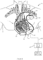
- FIG. 1 illustrates an exemplary heart treatment or support system 10 of the present invention.
- heart treatment system 10 includes an implantable blood pump 12 and an implantable cardiac rhythm management device 14.
- the blood pump refers to a ventricular assist system including a pump, battery, and peripherals.
- cardiac treatment system can be used to refer to one or more cardiovascular systems.
- heart treatment system refers to a combined system including two subsystems: a left ventricular assist system and a cardiac rhythm management system.
- the implantable blood pump 12 and the implantable cardiac rhythm management device 14 may be operatively coupled to one another by a communication line 16 to share information between the implanted devices.
- the implantable cardiac rhythm management device 14 may send information to the implantable blood pump 12 through the communication line 16.
- the implantable blood pump 12 may send information to the implantable cardiac rhythm management device 14 through the communication line 16.
- information may be passed from the implantable cardiac rhythm management device 14 to the implantable blood pump 12 and vice-versa.
- the blood pump 12 may be configured to couple with the circulatory system (e.g., heart 1) of the patient and to assist in pumping blood therethrough.
- the pump 12 includes a pump housing 18 and an inlet cannula 20 and an outlet 22 extending from the housing 18.
- the pump 12 may further include an external control module 23.
- the pump can be configured similar to an LVAD described in U.S. Patent Publication 2015/0290374 ; U.S. Patent Publication 2014/0188148 ; U.S. Patent No.: 9,091,271 ; U.S. Patent No. 8,794,989 , U.S. Patent No. 8,682,431 ; and/or U.S. Patent No. 8,894,561 .
- the housing 18 may house a rotor of the blood pump 12 an may also include on-board electronics 24 (e.g., processor, battery, sensors, etc.).
- the inlet cannula 20 may be configured to couple with a chamber of the heart 1 and the rotor of blood pump 12 may draw blood from a coupled heart chamber and output blood through output 22.
- the output 22 of the pump 12 may couple with a vascular graft assembly 26 which may be coupled with another portion of the patient's circulatory system (e.g., aorta, or the like) to deliver the pumped blood back into the circulatory system of the patient.
- an external control module 23 may be provided to send commands to and receive data from on-board electronics 24 of pump 12.
- the external control module 23 may be coupled with the pump by a percutaneous cable 27.
- one or more batteries 25 may be coupled with the external control module 23 to power the control module 23.
- the batteries 25 may be external batteries or internal batteries 25.
- pump 12 is generally illustrated as a centrifugal pump, it should be understood that the communications systems and methods described herein are not limited to centrifugal pumps, but are equally applicable to other pump designs (e.g., axial flow or mixed flow, etc.). Additionally, while pump 12 is illustrated as supporting the left ventricle, it should be understood that the pump 12 may be coupled with other portions of the heart 1, such as the right ventricle or other chambers of the heart 1, or other catheter or intravascular pump systems that couple to cardiovascular locations (e.g., descending aorta and other intravascular placements).
- the implantable cardiac rhythm management device 14 may be configured to couple with one or more portions of the heart 1 of the patient to pace, resynchronize, and/or sense electrical activity of the heart 1.
- the device 14 can be configured similar to a devices described in U.S. Patent 8,180,448 ; U.S. Patent 8,295,939 ; U.S. Patent 8,543,205 ; U.S. Patent 7,945,333 ; U.S. Patent 8,295,939 ; U.S. Patent 7,853,325 ; U.S. Patent 8,145,324 ; U.S. Patent 8,180,448 ; U.S. Patent 8,224,462 ; U.S. Patent 8,364,283 ; U.S.
- the implantable cardiac rhythm management device 14 may include a housing 28, a header 30, and one or more leads 32.
- the housing 28 may house on-board electronics 34 of the implantable cardiac rhythm management device 14 (e.g., processor, sensor(s), battery, etc.).
- the header 30 may provide an interface between the electronics 34 and the one or more leads 32 extending from the housing 28.
- the one or more leads 32 may operably couple the implantable cardiac rhythm management device 14 to the heart 1 of the patient for pacing, resynchronizing, and/or sensing electrical activity of the heart 1.
- the one or more leads 32 may couple the implantable cardiac rhythm management device 14 to the right ventricle, right atrium, left ventricle, and/or the left atrium depending on the type of implantable cardiac rhythm management device 14 and treatment needed.
- the implantable cardiac rhythm management device 14 may be a pacemaker, CRT, ICD, or the like. Additionally, while generally illustrated as coupling, e.g., via leads, with the endocardium, the implantable cardiac rhythm management device 14 may be configured to couple with portions of the epicardium to carry out its functions.
- Communication line 16 may couple the implantable blood pump 12 with the implantable cardiac rhythm management device 14 so that information may be shared from one implant to the other.
- the communication line 16 may have a first end that couples to the on-board electronics 34 of the implantable cardiac rhythm management device 14 and a second end that couples to the on-board electronics 24 of the implantable blood pump 12.
- the first end connects to the on-board electronics 34 of the implantable cardiac rhythm management device 14 through an open through-hole or plug in the header of the implantable cardiac rhythm management device 14.
- the communication line 16 provides an electrical connection between the implantable blood pump 12 and the implantable cardiac rhythm management device 14.
- the communication line 16 may be a lead that may be similar in configuration to the one or more leads 32. As such, the communication line 16 may couple to the on-board electronics 34 of the implantable cardiac rhythm management device 14 through the header 30.
- the communication line 16 may provide an optical connection between the implantable blood pump 12 and the implantable cardiac rhythm management device 14.
- An optical connection may be desirable in some situations because the optical cable may be more resistant to corrosion and infection during long term implantation of the implant 14 and may be faster and higher resolution signaling, compared to an implant using an electrical connection.
- an electrical connection may be beneficial in some situations as fewer modifications are required to existing implantable cardiac rhythm management devices.
- the heart treatment system 10 may improve patient treatment due to the fact that information may be shared between the implanted devices 12, 14.
- the implantable cardiac rhythm management device 14 may be configured to deliver heart stimulation pulses to the heart 1 of the patient to pace the patient's heart 1.
- Figure 2 illustrates an exemplary train of heart stimulation pulses 100 according to some embodiments.
- the heart stimulation pulses 100 may comprise a series of square wave signals.
- the train of heart stimulation pulses 100 delivered are pre-programmed at constant frequency.
- the implantable cardiac rhythm management device 14 may adjust the frequency of the train of heart stimulation pulses 100 based on the patient's needs.
- the on-board electronics 34 of the implantable cardiac rhythm management device 14 may include a sensor (e.g., activity sensor, accelerometer, timers) for estimating physical exertion by the patient and/or the time of day.
- the frequency of heart stimulation pulses 100 may be increased during higher activity (e.g., walking) and/or day time and lowered during lower activity (e.g., sleeping or resting) and/or night time.
- the implantable cardiac rhythm management device 14 may also be configured to deliver an electrical pace signal through the communication line 16 to the implantable blood pump 12 with each heart stimulation pulse delivered to the heart 1.
- the electrical pace signal delivered to the implantable blood pump 12 is similar or identical to the heart stimulation pulses 100 delivered to the heart 1 of the patient in frequency, voltage, and/or duration. This may be advantageous in reducing the power requirements for communication information between the implanted devices.
- the pump processor of the implantable blood pump 12 may be configured to receive the electrical pace signal from the implantable cardiac rhythm management device 14 and may adjust a pumping of the implantable blood pump 12 based on the received electrical pace signal.
- the implantable cardiac rhythm management device 14 is configured to adjust the frequency of the train of heart stimulation pulses 100 based on the patient's needs, so too will the frequency of the electrical pace signal delivered to the pump 12.
- an implantable blood pump 12 may provide additional pumping when the frequency of the electrical pace signal increases to further assist the patient's heart in pumping blood.
- the implantable blood pump 12 may decrease pumping when the frequency of the electrical pace signal decreases, indicating a lower heart rate and a decreased need for blood circulation.
- the implantable blood pump may leverage one or more activity sensors of the implantable cardiac rhythm management device to adjust pumping.
- the one or more activity sensors may comprise electrical pulse detection (e.g., heart rate sensing), one or more accelerometers, time stamp information for time of day information, etc.
- the implantable cardiac rhythm management device may be configured to detect patient activity or position (e.g., sitting, standing, laying, walking, running, etc.) or infer activity (e.g., using an internal clock to determine time of day or the like) and may adjust a pacing signal delivered to the heart and/or the pump.
- the implantable cardiac rhythm management device 14 may continuously adjust frequency of the heart stimulation pulses 100 and the electrical pace signal or may switch between one or more pre-programmed modes (e.g., high activity, low activity, resting, sleeping, etc.) to adjust for patient needs throughout the day.
- the implantable blood pump 12 may also continuously adjust pumping of blood in response to changes in frequency of the received electrical pace signal or may switch between one or more pre-programmed pumping modes.
- the pump processor may be configured to compare a frequency of the electrical pace signal with one or more frequency thresholds. In some embodiments, a first frequency threshold and a second frequency threshold that is greater than the first frequency threshold may be provided.
- the pump processor may adjust the pumping of the implantable blood pump 12 to a first speed when the frequency of the electrical pace signal is below the first frequency threshold, a second speed when the frequency of the electrical pace signal is above the first frequency threshold and below the second frequency threshold, and a third speed when the frequency of the electrical pace signal is above the first frequency threshold and the second frequency threshold.
- the first speed may be less than the second speed and the second speed may be less than the third speed.
- the implantable cardiac rhythm management device 14 may be configured to sense electrical signals from the heart 1 and may detect an abnormal heart rhythm of the patient based on the sensed electrical signals.
- the implantable cardiac rhythm management device 14 may deliver a unique series of electrical pulses through the communication line 16 to the pump processor of the implantable blood pump 12.
- the unique series of electrical pulses may be associated with the specific type of abnormal heart rhythm detected by the implantable cardiac rhythm management device 14.
- the series of electrical pulses comprise a series of simple square wave signals. This may be advantageous in reducing power requirements of the communications method.
- the pump processor may receive the unique series of electrical pulses and may decode the unique series of electrical pulses to determine the type of abnormal heart rhythm being experienced by the patient.
- the pump processor may be configured to adjust and implement a pumping protocol of the implantable blood pump 12 to account for the abnormal heart rhythm. For example, in some embodiments, the pump processor may temporarily cease operation of the pump in the event that fibrillation of the heart is sensed. After defibrillation, the pump 12 may resume pumping.
- the pump processor may decode the received unique series of electrical pulses using a look-up table. For example, the processor may compare the received series of electrical pulses to a database that stores a plurality of different possible signals and associates each of these possibilities with a type of abnormal heart rhythm. By identifying a match between the received signal and the signal stored in the database, the pump processor may then match the received signal with a specific type of abnormal heart rhythm signaled by the implantable cardiac rhythm management device 14.
- the pump processor may decode the received unique series of electrical using one or more thresholds.
- one or more frequency, voltage, and/or duration thresholds may be utilized to decode the received unique series of electrical pulses.
- the implantable cardiac rhythm management device 14 may be configured to deliver heart stimulation pulses 100 to the heart 1 and also configured to sense electrical signals from the heart to detect abnormal heart rhythms. Accordingly, in some embodiments, the implantable cardiac rhythm management device 14 may deliver an electrical pace signal through the communication line 16 to the implantable blood pump 12 with each heart stimulation pulse delivered to the heart 1 and also a unique series of electrical pulses through the communication line 16 to the pump processor of the implantable blood pump 12 when an abnormal heart rhythm is detected.
- the pump processor may differentiate the unique series of electrical pulses from the electrical pace signal 100 which the implantable cardiac rhythm management device 14 delivers simultaneously with the heart stimulation pulses and may associate the received unique series of pulses with a pumping protocol. Thereafter, the processor may implement the pumping protocol in response to receiving the unique series of pulses while also adjusting pumping for heart rate.
- Figures 3-6 illustrate a plurality of exemplary electrical pulses 200a-200d from an implantable cardiac rhythm management device 14 to a blood pump 12 to communication physiological information.
- the series of electrical pulses 200a may comprise a series of square wave signals.
- the series of electrical pulses 200a may include the electrical pace signal 100 that is associated with the heart stimulation pulses delivered to the patient.
- the series of electrical pulses 200a may also include the unique series of electrical pulses 300a associated with a type of abnormal heart rhythm detected by the implantable cardiac rhythm management device 14.
- the unique series of electrical pulses 300a may overlap in time with the electrical pace signal 100.
- the pump processor may differentiate the series of electrical pulses 300a from the pace signal 100 based on a voltage of the electrical pulses in the series of electrical pulses 200a.
- the voltage of the pace signal 100 may be higher or lower than the electrical pulses associated with the abnormal heart rhythm.
- the pump processor may utilize a voltage threshold to differentiate the series of electrical pulses 300a from the pace signal 100.
- the pump processor may adjust the pump 12 according to one or both of the signals received from the implantable cardiac rhythm management device 14. While the series of electrical pulses 300a is illustrated as including a plurality of higher voltage electrical pulses, it should be understood that a single higher or lower voltage pulse may be delivered to indicate the detection of an abnormal heart rhythm.
- Figure 4 illustrates another exemplary series of electrical pulses 200b from an implantable cardiac rhythm management device 14 to a blood pump 12 to communication physiological information.
- the pump 12 may differentiate the series of electrical pulses 300b (associated with the abnormal heart condition) from the pace signal 100 (associated with the heart stimulation signals) based on a frequency of the electrical pulses in the series of electrical pulses 200b.
- the electrical pulses 300b, associated with the abnormal heart rhythm may be delivered to the pump 12 at a higher frequency than the pacing signal 100.
- the pump processor may utilize a frequency threshold to differentiate the series of electrical pulses 300b from the pace signal 100.
- the pacing signal 100 is associated with a heart rate of the patient, it would be understood that there is an upper limit to this rate.
- the series of electrical pulses 300b associated with the abnormal heart rhythm may be delivered to the pump 12 at a frequency which exceeds the heart rate upper limit.
- the upper limit may be based on a highest expected heart rate for a heart failure patient.
- the upper limit may be 120 bpm in some instances, 150 bpm, 160 bpm, 200 bpm, or more (e.g., 250 bpm) in other instances.
- the implantable cardiac rhythm management device 14 may be preprogrammed with an maximum heart stimulation rate (e.g., for safety purposes or the like).
- the series of electrical pulses 300b associated with the abnormal heart rhythm may be delivered to the pump 12 at a frequency which exceeds the preprogrammed maximum heart stimulation rate of the implantable cardiac rhythm management device 14.
- the pump 12 when receiving electrical pulses that exceed this frequency threshold would automatically recognize that the series of pulses are associated with a type of abnormal heart rhythm and may proceed to decode the type detected. Thereafter, the pump processor may adjust the pump 12 accordingly.
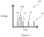
- Figure 5 illustrates another exemplary series of electrical pulses 200c from an implantable cardiac rhythm management device 14 to a blood pump 12 to communication physiological information.
- the pump processor may differentiate the electrical pulse 300c (associated with the abnormal heart condition) from the pace signal 100 (associated with the heart stimulation signals) based on a duration of the electrical pulses in the series of electrical pulses 200c.
- the electrical pulse 300c may have a longer duration than the pulses associated with the pace signal 100.
- the pump processor may utilize a pulse duration threshold to differentiate the electrical pulse 300c from the pace signal 100. While only a single electrical pulse 300c is illustrated, it should be understood that one or more electrical pulses 300c may be associated with different types of abnormal heart conditions. Additionally, more complex information may be transmitted to the pump 12 and decoded if electrical pulse 300c is transmitted in varying combinations of long pulses and short pulses, similar to Morse code.
- Figure 6 illustrates another exemplary series of electrical pulses 200d from an implantable cardiac rhythm management device 14 to a blood pump 12 to communication physiological information.
- the pump processor may differentiate the series of electrical pulses 300d from the pace signal 100 (associated with the heart stimulation signals) based on a duration, voltage and/or frequency of the electrical pulses in the series of electrical pulses 200c.
- the implantable cardiac rhythm management device 14 may be able to deliver more complex information including, but not limited to, the abnormal heart conditions detected by the implantable cardiac rhythm management device 14.
- the pump processor may adjust and implement the pump protocol, similar to the embodiments described above.
- a unique series of electrical pulses may be indicative of a start/stop to a communication.
- a first unique series of electrical pulses may be received by the pump 12 which are indicative of a start of communication.
- a second unique series of electrical pulses may follow the first unique series of electrical pulses which communicate specific information to the pump 12.
- a third unique series of electrical pulses may be indicative of a stop to communication.
- the first and third unique series of electrical pulses may be identical or different.
- the start communication signal may cause the pump processor to "wake up" and start receiving the second series of electrical pulses associated with the information transmitted by the implantable cardiac rhythm management device 14.
- the stop communication signal may cause the pump processor standby until the next start communication signal is received.
- the implantable cardiac rhythm management device and the implantable blood pump may be configured to communicate wirelessly.
- the implantable cardiac rhythm management device may encode information (sensed patient information, time stamps, etc.) and transmit the information by Bluetooth communication to the implantable blood pump.
- the implantable blood pump may be configured to receive the Bluetooth signal from the implantable cardiac rhythm management device and to decode the signal to determine the type of information sent from the implantable cardiac rhythm management device (e.g., heart rate information, abnormal heart rhythm detection, information associated with patient position or activity, etc.). Thereafter, the implantable blood pump may be configured to adjust a pumping operation (changing pumping modes, speeds, etc.).
- the implantable cardiac rhythm management device and implantable blood pump may communicate through the conductive pathways of the tissue, similar to the communication methods and systems described in U.S. Patent Publication No. 2007/0088397 . Accordingly, in some embodiments, the implantable cardiac rhythm management device may communicate by emitting an electric field which may be conducted through the tissue and detected by one or more sensors of the implantable blood pump.
- cardiac rhythm management device and/or the pump may not be fully implanted in other embodiments.
- One or more computing devices may be adapted to provide desired functionality by accessing software instructions rendered in a computer-readable form.
- any suitable programming, scripting, or other type of language or combinations of languages may be used to implement the teachings contained herein.
- software need not be used exclusively, or at all.
- some embodiments of the methods and systems set forth herein may also be implemented by hard-wired logic or other circuitry, including but not limited to application-specific circuits. Combinations of computer-executed software and hard-wired logic or other circuitry may be suitable as well.
- the methods disclosed herein may be executed by one or more suitable computing devices.
- Such system(s) may comprise one or more computing devices adapted to perform one or more embodiments of the methods disclosed herein.
- such devices may access one or more computer -readable media that embody computer-readable instructions which, when executed by at least one computer, cause the at least one computer to implement the methods of the present subject matter.
- the computing device(s) may comprise circuitry that renders the device(s) operative to implement one or more of the methods of the present subject matter.
- Any suitable computer-readable medium or media may be used to implement or practice the presently-disclosed subject matter, including but not limited to, diskettes, drives, and other magnetic-based storage media, optical storage media, including disks (e.g., CD-ROMS, DVD-ROMS, variants thereof, etc.), flash, RAM, ROM, and other memory devices, and the like.
Description
- The present invention generally relates to heart failure and disease state management systems, and in various respects, methods and systems for communicating information between an implantable blood pump and another device like a cardiac rhythm management device.
- Cardiovascular disease remains the leading cause of death globally. Nearly one third of deaths in the U.S. are caused by heart disease, stroke, and other cardiovascular diseases according to the American Heart Association. Nearly one in ten deaths have cardiovascular disease as a contributing factor. Because of the size of this epidemic-nearly 6 million adults in the United States live with heart failure-there remains a need for improving the early diagnosis and treatment of cardiovascular disease. Many people unknowingly live with heart disease until they experience a significant event.
-
US 2011/0178361 A1 relates to ventricular assist device incorporating a rotary pump such as a rotary impeller pump. The pump is in fluid communication with a ventricle and artery to assist blood flow from the ventricle to the artery. The device includes a pump drive circuit supplying power to the pump, one or more sensors for sensing one or more electrophysiological signals such as electrogram signals and a signal processing circuit connected to the sensors and to the pump drive circuit. The signal processing circuit is operative to detect sensor signals and control power supplied to the pump from the pump drive circuit so that the pump runs in a pulsatile mode, with a varying speed synchronized with the cardiac cycle. When an arrhythmia is detected, the pump drive circuit may also run the pump in an atrial arrhythmia mode or a ventricular arrhythmia mode different from the normal pulsatile mode. -
WO 2011/123789 A1 relates to combination heart assist systems, methods, and devices that include both an electrical therapy device and a mechanical heart assist device. Various operational mode can be implemented using these embodiments, including a synchronized pacing mode, an internal CPR mode, and an internal workout mode. - More recently, Ventricular Assist Devices (VADs) have become increasingly common for treating advanced heart failure. Advanced heart failure patients usually refers to patients in New York Heart Association (NYHA) Class III or IV. VAD therapy patients often have several comorbidities such as renal failure, respiratory failure, and other cardiovascular diseases. VAD patients often have other heart failure devices including implanted pacemakers (IPM), implantable cardioverter defibrillators (ICD), cardiac resynchronization therapy (CRT) devices, monitoring systems (e.g., CardioMEMS, implantable cardiac monitors, etc.), and/or other heart failure management devices. While VADs and implantable cardiac rhythm management devices separately provide beneficial heart assist functions, it may be advantageous to communicate information between the implanted devices to diagnose disease, improve therapy through device coordination, and more. And because these systems are not designed to interoperate at present, there is a need for systems and methods to establish communication and interoperability.
- There is a need for improved systems for diagnosing and treating heart disease. There is a need for systems and methods for coordinating one or more heart assist devices.
- The present invention generally relates to a heart treatment system as defined in
claim 1. The dependent claims define preferred embodiments of the heart treatment system. In some aspects, an implantable blood pump is provided. In some aspects, an implantable CRM/ICD or CRT device is provided. In still further aspects of the present invention, a heart assist system is provided that includes an implantable blood pump and an implantable cardiac rhythm management device in coordination with each other. Moreover, other aspects are generally related to methods of communication between two or more heart assist devices. - Communicating information between an implantable blood pump and an implantable cardiac rhythm management device can be beneficial. At first glance, such a goal may seem simple and straightforward, however such coordination between implanted devices comes with a variety of challenges. For instance, Medical Implant Communications Services (MICS) band radio transceivers, which are generally found in CRTs, IPMs and ICDs, may require high power demands for communicating information to the VAD. Such a communications scheme in turn may drastically reduce battery life of a pacemaker by several months to years and, thereby require more frequent and invasive replacement procedures. Similarly, such a communication scheme may require more frequent battery recharging of VAD systems, thereby requiring the patient to be tethered to a power source more frequently and inconveniencing the patient. As such, it may be advantageous to limit the power requirements for the communication scheme between the implanted devices because of the limited power source available to these implants. Accordingly, aspects of the present invention address one or more such challenges.
- For reference, a method of assisting a heart of a patient is provided. The method may include sensing a series of electrical pulses from an implantable cardiac rhythm management device electrically pacing the heart of the patient at a first frequency with electrical pulses with a first duration and first voltage. In various embodiments, the sensing can be performed using an implantable blood pump coupled to a heart of a patient. In various embodiments, a sensor is provided for performing the electrical pulse sensing, and the sensor outputs related information to the blood pump. The series of electrical pulses from the implantable cardiac rhythm management device sensed by the implantable blood pump may be associated with a type of abnormal heart rhythm detected by the implantable cardiac rhythm management device. Accordingly, in some embodiments, the implantable cardiac rhythm management device may be configured to sense the heart's electrical activity to determine when the heart is experiencing an abnormal heart rhythm. Additionally, the implantable cardiac rhythm management device may be configured to encode the detected information into the series of electrical pulses sent to the implantable blood pump to specifically identify a type of abnormal heart rhythm detected. For example, the series of electrical pulses may be provided at a second frequency different than the first frequency or may include electrical pulses with a second duration or second voltage different than the first duration or first voltage. The method may further include determining, with the implantable blood pump, the type of abnormal heart rhythm detected by the implantable cardiac rhythm management device by analyzing a frequency of the series of electrical pulses, durations of each of the electrical pulses of the series of electrical pulses, or voltages of each of the electrical pulses of the series of electrical pulses. Thereafter, a pumping protocol of the implantable blood pump may be adjusted based on the type of abnormal heart rhythm determined by the analysis.
- In some embodiments, the implantable blood pump may determine the type of abnormal heart rhythm by analyzing the frequency of the series of electrical pulses. In some embodiments, the implantable blood pump may determine the type of abnormal heart rhythm by referencing a database associating frequencies of sensed electrical pulses with types of abnormal heart rhythm and matches at type of abnormal heart rhythm with the received series of electrical pulses. In some embodiments, the implantable blood pump may determine the type of abnormal heart rhythm by comparing the frequency of the series of electrical pulses to one or more frequency thresholds.
- Optionally, the implantable blood pump may determine the type of abnormal heart rhythm by analyzing durations of each of the electrical pulses of the series of electrical pulses. The series of electrical pulses may comprise a first pulse with a first duration and a second pulse with a second duration that is different than the first pulse.
- In some embodiments, the type of abnormal heart rhythm may be determined to be a fibrillation of the heart and the pumping protocol may be adjusted to cease the pumping of the implantable blood pump for a predetermined duration of time.
- For reference, a heart assist system may be provided. The system may include an implantable blood pump configured to couple with a circulatory system of a patient and to pump blood therethrough. The implantable blood pump may include a pump processor configured to sense a series of electrical pulses from an implantable cardiac rhythm management device electrically pacing the heart of the patient at a first frequency with electrical pulses with a first duration and a first voltage. The series of electrical pulses from the implantable cardiac rhythm management device configured to be sensed by the pump processor may be associated with a type of abnormal heart rhythm detected by the implantable cardiac rhythm management device and may be at a second frequency different than the first frequency or including electrical pulses with a second duration different than the first duration or a second voltage different than the first voltage. The pump processor may be configured to determine the type of abnormal heart rhythm detected by the implantable cardiac rhythm management device by analyzing a frequency of the series of electrical pulses, durations of each of the electrical pulses of the series of electrical pulses or voltages of each of the electrical pulses of the series of electrical pulses. The pump processor can be configured to adjust a pumping protocol of the implantable blood pump based on the type of abnormal heart rhythm determined by the analysis.
- In some embodiments, the pump processor may be configured to determine the type of abnormal heart rhythm by analyzing the frequency of the series of electrical pulses. In some embodiments, the pump processor may be configured to determine the type of abnormal heart rhythm by referencing a database associating frequencies of sensed electrical pulses with types of abnormal heart rhythm. Optionally, the pump processor may determine the type of abnormal heart rhythm by comparing the frequency of the series of electrical pulses to one or more frequency thresholds.
- In some embodiments, the pump processor may determine the type of abnormal heart rhythm by analyzing durations of each of the electrical pulses of the series of electrical pulses. The series of electrical pulses may include a first pulse with a first duration and a second pulse with a second duration that is different than the first pulse.
- In some embodiments, when the type of abnormal heart rhythm is determined to be a fibrillation of the heart, the pumping processor may adjust the pumping protocol to cease the pumping of the implantable blood pump for a predetermined duration of time.
- Optionally, the electrical pulses of the series of electrical pulses may comprise square wave signals.
- For reference, a method of assisting a heart of a patient. The method may include receiving, through a first lead having a first end coupled with an implantable cardiac rhythm management device and a second end opposite the first end coupled with a pump processor of an implantable blood pump, an electrical pace signal from the implantable cardiac rhythm management device. The implantable cardiac rhythm management device may be configured to deliver the electrical pace signal to pump processor of the implantable blood pump with each heart stimulation pulse delivered to the heart of the patient by the implantable cardiac rhythm management device. A pumping of the implantable blood pump may be adjusted based on the received electrical pace signal with the pump processor.
- The electrical pace signal may be a square wave signal with a frequency equal to a heart rate of the patient.
- The pump processor may be configured to compare a frequency of the electrical pace signal with a first frequency threshold and a second frequency threshold that is greater than the first frequency threshold.
- Optionally, the pump processor may adjust the pumping of the implantable blood pump to a first speed when the frequency of the electrical pace signal is below the first frequency threshold, a second speed when the frequency of the electrical pace signal is above the first frequency threshold and below the second frequency threshold, and a third speed when the frequency of the electrical pace signal is above the first frequency threshold and the second frequency threshold. The first speed may be less than the second speed and the second speed may be less than the third speed.
- The method may also include detecting, with the implantable cardiac rhythm management device, an abnormal heart rhythm of the heart of the patient, and delivering, with the implantable cardiac rhythm management device, a unique series of electrical pulses through the first lead to the pump processor of the implantable blood pump. Thereafter, the method may include differentiating, with the pump processor, the unique series of electrical pulses from the electrical pace signal which the implantable cardiac rhythm management device delivers simultaneously with the heart stimulation pulses. The received unique series of pulses may then be associated with a pumping protocol and the pumping protocol may be implemented in response to receiving the unique series of pulses.
- In some embodiments, the pump processor may differentiate the unique series of electrical pulses from the electrical pace signal based on a duration of the electrical pulses of the unique series of electrical pulses.
- In some embodiments, the pump processor may differentiate the unique series of electrical pulses from the electrical pace signal based on a frequency of the unique series of electrical pulses.
- In some embodiments, the pump processor may compare the frequency of the unique series of electrical pulses to a threshold frequency to differentiate the unique series of electrical pulses from the electrical pace signal.
- In some embodiments, electrical pulses of the unique series of electrical pulses may comprise a combination of a first pulse with a first duration and second pulse with a second duration different that the first pulse.
- In some embodiments, the pump protocol may be a cessation of pumping for a predetermined duration of time.
- In an embodiment according to the present invention, a heart treatment system is provided that includes an implantable blood pump configured to couple with a circulatory system of a patient and to pump blood therethrough. The implantable blood pump includes a pump processor, the pump processor including an input. An implantable cardiac rhythm management device is provided that is configured to deliver heart stimulation pulses to a heart of the patient. A first lead having a first end and a second end opposite the first end are provided. The first end of the first lead couples with the implantable cardiac rhythm management device and the second end of the first lead couples with the input of the pump processor.
- The implantable cardiac rhythm management (CRM) device is configured to deliver an electrical pace signal through the first lead to the implantable blood pump. This may be with each heart stimulation pulse delivered to the heart of the patient. The pump processor of the implantable blood pump is configured to receive the electrical pace signal from the implantable cardiac rhythm management device and to adjust a pumping of the implantable blood pump based on the received electrical pace signal.
- In various embodiments, a sensor system may be provided for sensing the pulses from the CRM device. In various embodiments, a detector may be provided in the VAD for receiving the signals from the CRM device. A converter in the VAD may be provided to convert the signals in the frequency and/or time domain. A converter may be provided to convert the signals between AC and/or DC.
- In some embodiments, the electrical pace signal may comprise a square wave signal with a frequency equal to a heart rate of the patient.
- In some embodiments, the pump processor of the implantable blood pump may be configured to compare a frequency of the electrical pace signal with a first frequency threshold and a second frequency threshold that is greater than the first frequency threshold. For example, the processor of the implantable blood pump may adjust the pumping of the implantable blood pump to a first speed when the frequency of the electrical pace signal is below the first frequency threshold, a second speed when the frequency of the electrical pace signal is above the first frequency threshold and below the second frequency threshold, and a third speed when the frequency of the electrical pace signal is above the first frequency threshold and the second frequency threshold. The first speed may be less than the second speed and the second speed may be less than the third speed.
- In some embodiments, the implantable cardiac rhythm management device may comprise a pacemaker. Optionally, the pacemaker may comprise one or more second leads, a header, and internal circuitry for coordinating pacing the heart of the patient with the one or more second leads. The one or more second leads may couple to the internal circuitry through the header of the pacemaker. The first lead may couple the internal circuitry of the pacemaker to the input of the pump processor of the implantable blood pump through the header of the pacemaker. In some embodiments, the one or more second leads and the first lead may have the same configuration.
- In some embodiments, the implantable cardiac rhythm management device may be configured to detect an abnormal heart rhythm of the heart of the patient. The implantable cardiac rhythm management device may also be configured to deliver a unique series of electrical pulses through the first lead to the pump processor of the implantable blood pump. The pump processor may differentiate the unique series of electrical pulses from the electrical pace signal which the implantable cardiac rhythm management device delivers simultaneously with the heart stimulation pulses and may associate the received unique series of pulses with a pumping protocol. Thereafter, the processor may implement the pumping protocol in response to receiving the unique series of pulses.
- In some embodiments, the pump processor may differentiate the unique series of electrical pulses from the electrical pace signal based on a duration or a voltage of the electrical pulses of the unique series of electrical pulses.
- In some embodiments, the pump processor may differentiate the unique series of electrical pulses from the electrical pace signal based on a frequency of the unique series of electrical pulses. For example, the pump processor may be configured to compare the frequency of the unique series of electrical pulses to a threshold frequency to differentiate the unique series of electrical pulses from the electrical pace signal.
- Optionally, electrical pulses of the unique series of electrical pulses may comprise a combination of a first pulse with a first duration and a second pulse with a second duration different from the first pulse.
- Various aspects of the disclosure, however without forming part of the claimed invention, are directed to a method of detecting heart failure comprising using the system(s) according to any of paragraphs [0026] to [0035].
- Embodiments of the invention covered by this patent are defined by the claims below, not this summary. This summary is a high-level overview of various aspects of the invention and introduces some of the concepts that are further described in the Detailed Description section below. This summary is not intended to identify key or essential features of the claimed subject matter, nor is it intended to be used in isolation to determine the scope of the claimed subject matter. The subject matter should be understood by reference to appropriate portions of the entire specification of this patent, any or all drawings, and each claim.
- The invention will be better understood upon reading the following description and examining the figures which accompany it. These figures are provided by way of illustration only and are in no way limiting on the invention.
- Further details, aspects, and embodiments of the invention will be described by way of example only and with reference to the drawings. In the drawings, like reference numbers are used to identify like or functionally similar elements. Elements in the figures are illustrated for simplicity and clarity and have not necessarily been drawn to scale.
-
Figure 1 illustrates an exemplary system of the present invention. -
Figure 2 illustrates an exemplary train of heart stimulation pulses according to some embodiments. -
Figure 3 illustrates an exemplary series of electrical pulses from an implantable cardiac rhythm management device to a blood pump to communication physiological information. -
Figure 4 illustrates another exemplary series of electrical pulses from an implantable cardiac rhythm management device to a blood pump to communication physiological information. -
Figure 5 illustrates another exemplary series of electrical pulses from an implantable cardiac rhythm management device to a blood pump to communication physiological information. -
Figure 6 illustrates another exemplary series of electrical pulses from an implantable cardiac rhythm management device to a blood pump to communication physiological information. - The present invention generally relates to heart assist systems and in particular systems for communicating information between an implantable blood pump and an implantable cardiac rhythm management device.
-
Figure 1 illustrates an exemplary heart treatment orsupport system 10 of the present invention. As used herein, "heart treatment system," "heart support system," and "cardiovascular system" are used somewhat interchangeably.Heart treatment system 10 includes animplantable blood pump 12 and an implantable cardiacrhythm management device 14. In various embodiments, the blood pump refers to a ventricular assist system including a pump, battery, and peripherals. In various respects, "heart treatment system" can be used to refer to one or more cardiovascular systems. In one example, heart treatment system refers to a combined system including two subsystems: a left ventricular assist system and a cardiac rhythm management system. In some embodiments, theimplantable blood pump 12 and the implantable cardiacrhythm management device 14 may be operatively coupled to one another by acommunication line 16 to share information between the implanted devices. In some embodiments, the implantable cardiacrhythm management device 14 may send information to theimplantable blood pump 12 through thecommunication line 16. In other embodiments theimplantable blood pump 12 may send information to the implantable cardiacrhythm management device 14 through thecommunication line 16. And in further aspects, information may be passed from the implantable cardiacrhythm management device 14 to theimplantable blood pump 12 and vice-versa. - The
blood pump 12 may be configured to couple with the circulatory system (e.g., heart 1) of the patient and to assist in pumping blood therethrough. In some embodiments, thepump 12 includes apump housing 18 and aninlet cannula 20 and anoutlet 22 extending from thehousing 18. In some embodiments, thepump 12 may further include anexternal control module 23. In some embodiments, the pump can be configured similar to an LVAD described inU.S. Patent Publication 2015/0290374 ;U.S. Patent Publication 2014/0188148 ;U.S. Patent No.: 9,091,271 U.S. Patent No. 8,794,989 ,U.S. Patent No. 8,682,431 ; and/orU.S. Patent No. 8,894,561 . - The
housing 18 may house a rotor of theblood pump 12 an may also include on-board electronics 24 (e.g., processor, battery, sensors, etc.). Theinlet cannula 20 may be configured to couple with a chamber of theheart 1 and the rotor ofblood pump 12 may draw blood from a coupled heart chamber and output blood throughoutput 22. Theoutput 22 of thepump 12 may couple with avascular graft assembly 26 which may be coupled with another portion of the patient's circulatory system (e.g., aorta, or the like) to deliver the pumped blood back into the circulatory system of the patient. - In some embodiments, an
external control module 23 may be provided to send commands to and receive data from on-board electronics 24 ofpump 12. Theexternal control module 23 may be coupled with the pump by apercutaneous cable 27. In some embodiments, one ormore batteries 25 may be coupled with theexternal control module 23 to power thecontrol module 23. Thebatteries 25 may be external batteries orinternal batteries 25. - While
pump 12 is generally illustrated as a centrifugal pump, it should be understood that the communications systems and methods described herein are not limited to centrifugal pumps, but are equally applicable to other pump designs (e.g., axial flow or mixed flow, etc.). Additionally, whilepump 12 is illustrated as supporting the left ventricle, it should be understood that thepump 12 may be coupled with other portions of theheart 1, such as the right ventricle or other chambers of theheart 1, or other catheter or intravascular pump systems that couple to cardiovascular locations (e.g., descending aorta and other intravascular placements). - The implantable cardiac
rhythm management device 14 may be configured to couple with one or more portions of theheart 1 of the patient to pace, resynchronize, and/or sense electrical activity of theheart 1. In some embodiments, thedevice 14 can be configured similar to a devices described inU.S. Patent 8,180,448 ;U.S. Patent 8,295,939 ;U.S. Patent 8,543,205 ;U.S. Patent 7,945,333 ;U.S. Patent 8,295,939 ;U.S. Patent 7,853,325 ;U.S. Patent 8,145,324 ;U.S. Patent 8,180,448 ;U.S. Patent 8,224,462 ;U.S. Patent 8,364,283 ;U.S. Patent 8,712,544 ;U.S. Patent 8,897,887 ;U.S. Patent 7,245,117 ;U.S. Patent 7,439,723 ;U.S. Patent 7,498,799 ;U.S. Patent 7,550,978 ;U.S. Patent 7,679,355 ;U.S. Patent 7,839,153 ;U.S. Patent 6,111,520 ; and/orU.S. Patent 6,278,379 . In some embodiments, the implantable cardiacrhythm management device 14 may include ahousing 28, aheader 30, and one or more leads 32. - The
housing 28 may house on-board electronics 34 of the implantable cardiac rhythm management device 14 (e.g., processor, sensor(s), battery, etc.). Theheader 30 may provide an interface between theelectronics 34 and the one or more leads 32 extending from thehousing 28. - The one or more leads 32 may operably couple the implantable cardiac
rhythm management device 14 to theheart 1 of the patient for pacing, resynchronizing, and/or sensing electrical activity of theheart 1. The one or more leads 32 may couple the implantable cardiacrhythm management device 14 to the right ventricle, right atrium, left ventricle, and/or the left atrium depending on the type of implantable cardiacrhythm management device 14 and treatment needed. - In some embodiments, the implantable cardiac
rhythm management device 14 may be a pacemaker, CRT, ICD, or the like. Additionally, while generally illustrated as coupling, e.g., via leads, with the endocardium, the implantable cardiacrhythm management device 14 may be configured to couple with portions of the epicardium to carry out its functions. -
Communication line 16 may couple theimplantable blood pump 12 with the implantable cardiacrhythm management device 14 so that information may be shared from one implant to the other. For example, thecommunication line 16 may have a first end that couples to the on-board electronics 34 of the implantable cardiacrhythm management device 14 and a second end that couples to the on-board electronics 24 of theimplantable blood pump 12. In some embodiments, the first end connects to the on-board electronics 34 of the implantable cardiacrhythm management device 14 through an open through-hole or plug in the header of the implantable cardiacrhythm management device 14. In some embodiments, thecommunication line 16 provides an electrical connection between theimplantable blood pump 12 and the implantable cardiacrhythm management device 14. Optionally, thecommunication line 16 may be a lead that may be similar in configuration to the one or more leads 32. As such, thecommunication line 16 may couple to the on-board electronics 34 of the implantable cardiacrhythm management device 14 through theheader 30. - In certain embodiments, the
communication line 16 may provide an optical connection between theimplantable blood pump 12 and the implantable cardiacrhythm management device 14. An optical connection may be desirable in some situations because the optical cable may be more resistant to corrosion and infection during long term implantation of theimplant 14 and may be faster and higher resolution signaling, compared to an implant using an electrical connection. However, an electrical connection may be beneficial in some situations as fewer modifications are required to existing implantable cardiac rhythm management devices. - As set forth above, the
heart treatment system 10 may improve patient treatment due to the fact that information may be shared between the implanteddevices rhythm management device 14 may be configured to deliver heart stimulation pulses to theheart 1 of the patient to pace the patient'sheart 1.Figure 2 illustrates an exemplary train ofheart stimulation pulses 100 according to some embodiments. In some embodiments, theheart stimulation pulses 100 may comprise a series of square wave signals. - In some embodiments, the train of
heart stimulation pulses 100 delivered are pre-programmed at constant frequency. Optionally, the implantable cardiacrhythm management device 14 may adjust the frequency of the train ofheart stimulation pulses 100 based on the patient's needs. For example, in some embodiments, the on-board electronics 34 of the implantable cardiacrhythm management device 14 may include a sensor (e.g., activity sensor, accelerometer, timers) for estimating physical exertion by the patient and/or the time of day. The frequency ofheart stimulation pulses 100 may be increased during higher activity (e.g., walking) and/or day time and lowered during lower activity (e.g., sleeping or resting) and/or night time. - In some embodiments, in addition to delivering
heart stimulation pulses 100 to theheart 1 of the patient, the implantable cardiacrhythm management device 14 may also be configured to deliver an electrical pace signal through thecommunication line 16 to theimplantable blood pump 12 with each heart stimulation pulse delivered to theheart 1. In at least some embodiments, the electrical pace signal delivered to theimplantable blood pump 12 is similar or identical to theheart stimulation pulses 100 delivered to theheart 1 of the patient in frequency, voltage, and/or duration. This may be advantageous in reducing the power requirements for communication information between the implanted devices. - The pump processor of the
implantable blood pump 12 may be configured to receive the electrical pace signal from the implantable cardiacrhythm management device 14 and may adjust a pumping of theimplantable blood pump 12 based on the received electrical pace signal. In embodiments where the implantable cardiacrhythm management device 14 is configured to adjust the frequency of the train ofheart stimulation pulses 100 based on the patient's needs, so too will the frequency of the electrical pace signal delivered to thepump 12. In response, animplantable blood pump 12 may provide additional pumping when the frequency of the electrical pace signal increases to further assist the patient's heart in pumping blood. Similarly, theimplantable blood pump 12 may decrease pumping when the frequency of the electrical pace signal decreases, indicating a lower heart rate and a decreased need for blood circulation. Such adjustments in blood pumping may be advantageous in reducing adverse events in pumping action (e.g., suction events or the like). As such, the implantable blood pump may leverage one or more activity sensors of the implantable cardiac rhythm management device to adjust pumping. The one or more activity sensors may comprise electrical pulse detection (e.g., heart rate sensing), one or more accelerometers, time stamp information for time of day information, etc. Thus, the implantable cardiac rhythm management device may be configured to detect patient activity or position (e.g., sitting, standing, laying, walking, running, etc.) or infer activity (e.g., using an internal clock to determine time of day or the like) and may adjust a pacing signal delivered to the heart and/or the pump. - In some embodiments, the implantable cardiac
rhythm management device 14 may continuously adjust frequency of theheart stimulation pulses 100 and the electrical pace signal or may switch between one or more pre-programmed modes (e.g., high activity, low activity, resting, sleeping, etc.) to adjust for patient needs throughout the day. Similarly, theimplantable blood pump 12 may also continuously adjust pumping of blood in response to changes in frequency of the received electrical pace signal or may switch between one or more pre-programmed pumping modes. For example, the pump processor may be configured to compare a frequency of the electrical pace signal with one or more frequency thresholds. In some embodiments, a first frequency threshold and a second frequency threshold that is greater than the first frequency threshold may be provided. The pump processor may adjust the pumping of theimplantable blood pump 12 to a first speed when the frequency of the electrical pace signal is below the first frequency threshold, a second speed when the frequency of the electrical pace signal is above the first frequency threshold and below the second frequency threshold, and a third speed when the frequency of the electrical pace signal is above the first frequency threshold and the second frequency threshold. The first speed may be less than the second speed and the second speed may be less than the third speed. - While the example above is described using two separate thresholds and three separate speeds or pumping modes, it should be understood that one or more frequency thresholds and two or more speeds and/or pumping modes may be utilized in other embodiments.
- In some embodiments, the implantable cardiac
rhythm management device 14 may be configured to sense electrical signals from theheart 1 and may detect an abnormal heart rhythm of the patient based on the sensed electrical signals. Optionally, the implantable cardiacrhythm management device 14 may deliver a unique series of electrical pulses through thecommunication line 16 to the pump processor of theimplantable blood pump 12. The unique series of electrical pulses may be associated with the specific type of abnormal heart rhythm detected by the implantable cardiacrhythm management device 14. In some embodiments, the series of electrical pulses comprise a series of simple square wave signals. This may be advantageous in reducing power requirements of the communications method. - The pump processor may receive the unique series of electrical pulses and may decode the unique series of electrical pulses to determine the type of abnormal heart rhythm being experienced by the patient. In response, the pump processor may be configured to adjust and implement a pumping protocol of the
implantable blood pump 12 to account for the abnormal heart rhythm. For example, in some embodiments, the pump processor may temporarily cease operation of the pump in the event that fibrillation of the heart is sensed. After defibrillation, thepump 12 may resume pumping. - In some embodiments, the pump processor may decode the received unique series of electrical pulses using a look-up table. For example, the processor may compare the received series of electrical pulses to a database that stores a plurality of different possible signals and associates each of these possibilities with a type of abnormal heart rhythm. By identifying a match between the received signal and the signal stored in the database, the pump processor may then match the received signal with a specific type of abnormal heart rhythm signaled by the implantable cardiac
rhythm management device 14. - Optionally, the pump processor may decode the received unique series of electrical using one or more thresholds. For example, one or more frequency, voltage, and/or duration thresholds may be utilized to decode the received unique series of electrical pulses.
- In some embodiments, the implantable cardiac
rhythm management device 14 may be configured to deliverheart stimulation pulses 100 to theheart 1 and also configured to sense electrical signals from the heart to detect abnormal heart rhythms. Accordingly, in some embodiments, the implantable cardiacrhythm management device 14 may deliver an electrical pace signal through thecommunication line 16 to theimplantable blood pump 12 with each heart stimulation pulse delivered to theheart 1 and also a unique series of electrical pulses through thecommunication line 16 to the pump processor of theimplantable blood pump 12 when an abnormal heart rhythm is detected. The pump processor may differentiate the unique series of electrical pulses from theelectrical pace signal 100 which the implantable cardiacrhythm management device 14 delivers simultaneously with the heart stimulation pulses and may associate the received unique series of pulses with a pumping protocol. Thereafter, the processor may implement the pumping protocol in response to receiving the unique series of pulses while also adjusting pumping for heart rate. - For example,
Figures 3-6 illustrate a plurality of exemplaryelectrical pulses 200a-200d from an implantable cardiacrhythm management device 14 to ablood pump 12 to communication physiological information. InFigure 3 , the series ofelectrical pulses 200a may comprise a series of square wave signals. The series ofelectrical pulses 200a may include theelectrical pace signal 100 that is associated with the heart stimulation pulses delivered to the patient. Additionally, the series ofelectrical pulses 200a may also include the unique series ofelectrical pulses 300a associated with a type of abnormal heart rhythm detected by the implantable cardiacrhythm management device 14. As illustrated, in some embodiments, the unique series ofelectrical pulses 300a may overlap in time with theelectrical pace signal 100. In this embodiment, the pump processor may differentiate the series ofelectrical pulses 300a from thepace signal 100 based on a voltage of the electrical pulses in the series ofelectrical pulses 200a. For example, the voltage of thepace signal 100 may be higher or lower than the electrical pulses associated with the abnormal heart rhythm. Accordingly, in some embodiments, the pump processor may utilize a voltage threshold to differentiate the series ofelectrical pulses 300a from thepace signal 100. After differentiating the series ofelectrical pulses 300a from thepace signal 100, the pump processor may adjust thepump 12 according to one or both of the signals received from the implantable cardiacrhythm management device 14. While the series ofelectrical pulses 300a is illustrated as including a plurality of higher voltage electrical pulses, it should be understood that a single higher or lower voltage pulse may be delivered to indicate the detection of an abnormal heart rhythm. -
Figure 4 illustrates another exemplary series ofelectrical pulses 200b from an implantable cardiacrhythm management device 14 to ablood pump 12 to communication physiological information. Thepump 12 may differentiate the series ofelectrical pulses 300b (associated with the abnormal heart condition) from the pace signal 100 (associated with the heart stimulation signals) based on a frequency of the electrical pulses in the series ofelectrical pulses 200b. For example, theelectrical pulses 300b, associated with the abnormal heart rhythm, may be delivered to thepump 12 at a higher frequency than thepacing signal 100. Accordingly, in some embodiments, the pump processor may utilize a frequency threshold to differentiate the series ofelectrical pulses 300b from thepace signal 100. For example, given that thepacing signal 100 is associated with a heart rate of the patient, it would be understood that there is an upper limit to this rate. The series ofelectrical pulses 300b associated with the abnormal heart rhythm may be delivered to thepump 12 at a frequency which exceeds the heart rate upper limit. For example, in some embodiments, the upper limit may be based on a highest expected heart rate for a heart failure patient. For example, the upper limit may be 120 bpm in some instances, 150 bpm, 160 bpm, 200 bpm, or more (e.g., 250 bpm) in other instances. Optionally, the implantable cardiacrhythm management device 14 may be preprogrammed with an maximum heart stimulation rate (e.g., for safety purposes or the like). The series ofelectrical pulses 300b associated with the abnormal heart rhythm may be delivered to thepump 12 at a frequency which exceeds the preprogrammed maximum heart stimulation rate of the implantable cardiacrhythm management device 14. As such, thepump 12, when receiving electrical pulses that exceed this frequency threshold would automatically recognize that the series of pulses are associated with a type of abnormal heart rhythm and may proceed to decode the type detected. Thereafter, the pump processor may adjust thepump 12 accordingly. -
Figure 5 illustrates another exemplary series ofelectrical pulses 200c from an implantable cardiacrhythm management device 14 to ablood pump 12 to communication physiological information. In this embodiment, the pump processor may differentiate theelectrical pulse 300c (associated with the abnormal heart condition) from the pace signal 100 (associated with the heart stimulation signals) based on a duration of the electrical pulses in the series ofelectrical pulses 200c. For example, theelectrical pulse 300c may have a longer duration than the pulses associated with thepace signal 100. Accordingly, in some embodiments, the pump processor may utilize a pulse duration threshold to differentiate theelectrical pulse 300c from thepace signal 100. While only a singleelectrical pulse 300c is illustrated, it should be understood that one or moreelectrical pulses 300c may be associated with different types of abnormal heart conditions. Additionally, more complex information may be transmitted to thepump 12 and decoded ifelectrical pulse 300c is transmitted in varying combinations of long pulses and short pulses, similar to Morse code. -
Figure 6 illustrates another exemplary series ofelectrical pulses 200d from an implantable cardiacrhythm management device 14 to ablood pump 12 to communication physiological information. The pump processor may differentiate the series ofelectrical pulses 300d from the pace signal 100 (associated with the heart stimulation signals) based on a duration, voltage and/or frequency of the electrical pulses in the series ofelectrical pulses 200c. By varying the voltage, duration, and/or frequency of the electrical pulses of theseries 300d, the implantable cardiacrhythm management device 14 may be able to deliver more complex information including, but not limited to, the abnormal heart conditions detected by the implantable cardiacrhythm management device 14. Thereafter, the pump processor may adjust and implement the pump protocol, similar to the embodiments described above. - In some embodiments, a unique series of electrical pulses may be indicative of a start/stop to a communication. For example, a first unique series of electrical pulses may be received by the
pump 12 which are indicative of a start of communication. A second unique series of electrical pulses may follow the first unique series of electrical pulses which communicate specific information to thepump 12. A third unique series of electrical pulses may be indicative of a stop to communication. The first and third unique series of electrical pulses may be identical or different. The start communication signal may cause the pump processor to "wake up" and start receiving the second series of electrical pulses associated with the information transmitted by the implantable cardiacrhythm management device 14. Similarly the stop communication signal may cause the pump processor standby until the next start communication signal is received. - In some embodiments, the implantable cardiac rhythm management device and the implantable blood pump may be configured to communicate wirelessly. For example in some embodiments, the implantable cardiac rhythm management device may encode information (sensed patient information, time stamps, etc.) and transmit the information by Bluetooth communication to the implantable blood pump. As such, the implantable blood pump may be configured to receive the Bluetooth signal from the implantable cardiac rhythm management device and to decode the signal to determine the type of information sent from the implantable cardiac rhythm management device (e.g., heart rate information, abnormal heart rhythm detection, information associated with patient position or activity, etc.). Thereafter, the implantable blood pump may be configured to adjust a pumping operation (changing pumping modes, speeds, etc.).
- In some embodiments, the implantable cardiac rhythm management device and implantable blood pump may communicate through the conductive pathways of the tissue, similar to the communication methods and systems described in
U.S. Patent Publication No. 2007/0088397 . Accordingly, in some embodiments, the implantable cardiac rhythm management device may communicate by emitting an electric field which may be conducted through the tissue and detected by one or more sensors of the implantable blood pump. - While the above systems are generally described for communication between implanted devices, it should be understood that the cardiac rhythm management device and/or the pump may not be fully implanted in other embodiments.
- One or more computing devices may be adapted to provide desired functionality by accessing software instructions rendered in a computer-readable form. When software is used, any suitable programming, scripting, or other type of language or combinations of languages may be used to implement the teachings contained herein. However, software need not be used exclusively, or at all. For example, some embodiments of the methods and systems set forth herein may also be implemented by hard-wired logic or other circuitry, including but not limited to application-specific circuits. Combinations of computer-executed software and hard-wired logic or other circuitry may be suitable as well.
- The methods disclosed herein may be executed by one or more suitable computing devices. Such system(s) may comprise one or more computing devices adapted to perform one or more embodiments of the methods disclosed herein. As noted above, such devices may access one or more computer -readable media that embody computer-readable instructions which, when executed by at least one computer, cause the at least one computer to implement the methods of the present subject matter. Additionally or alternatively, the computing device(s) may comprise circuitry that renders the device(s) operative to implement one or more of the methods of the present subject matter.
- Any suitable computer-readable medium or media may be used to implement or practice the presently-disclosed subject matter, including but not limited to, diskettes, drives, and other magnetic-based storage media, optical storage media, including disks (e.g., CD-ROMS, DVD-ROMS, variants thereof, etc.), flash, RAM, ROM, and other memory devices, and the like.
- The subject matter of the present invention is described here with specificity, but the claimed subject matter may be embodied in other ways, may include different elements or steps, and may be used in conjunction with other existing or future technologies.
- This description should not be interpreted as implying any particular order or arrangement among or between various steps or elements except when the order of individual steps or arrangement of elements is explicitly described. Different arrangements of the components depicted in the drawings or described above, as well as components and steps not shown or described are possible. Similarly, some features and sub-combinations are useful and may be employed without reference to other features and sub-combinations. Embodiments of the invention have been described for illustrative and not restrictive purposes, and alternative embodiments will become apparent to readers of this patent. Accordingly, the present invention is not limited to the embodiments described above or depicted in the drawings, and various embodiments and modifications may be made without departing from the scope of the claims below.
Claims (15)
- A heart treatment system (10), comprising:an implantable blood pump (12) configured to couple with a circulatory system of a patient and to pump blood therethrough, the implantable blood pump (12) comprising a pump processor, the pump processor including an input;an implantable cardiac rhythm management device (14) configured to deliver heart stimulation pulses to a heart (1) of the patient;a first lead having a first end and a second end opposite the first end, the first end of the first lead coupling with the implantable cardiac rhythm management device (14) and the second end of the first lead coupled with the input of the pump processor;wherein the implantable cardiac rhythm management device (14) is configured to deliver an electrical pace signal (100) through the first lead to the implantable blood pump (12); andwherein the pump processor of the implantable blood pump (12) is configured to receive the electrical pace signal (100) from the implantable cardiac rhythm management device (14) and to adjust a pumping of the implantable blood pump (12) based on the electrical pace signal (100).
- The heart treatment system of claim 1, wherein the implantable cardiac rhythm management device (14) is configured to deliver the electrical pace signal (100) through the first lead to the implantable blood pump (12) with each heart stimulation pulse delivered to the heart (1) of the patient.
- The heart treatment system of any of claims 1-2, wherein the electrical pace signal (100) comprises a square wave signal with a frequency equal to a heart rate of the patient.
- The heart treatment system of any of claims 1-3, wherein the pump processor of the implantable blood pump (12) is configured to compare a frequency of the electrical pace signal (100) with a first frequency threshold and a second frequency threshold that is greater than the first frequency threshold.
- The heart treatment system of claim 4, wherein the pump processor of the implantable blood pump (12) adjusts the pumping of the implantable blood pump (12) to a first speed when the frequency of the electrical pace signal (100) is below the first frequency threshold, a second speed when the frequency of the electrical pace signal (100) is above the first frequency threshold and below the second frequency threshold, and a third speed when the frequency of the electrical pace signal (100) is above the first frequency threshold and the second frequency threshold, the first speed being less than the second speed and the second speed being less than the third speed.
- The heart treatment system of any of claims 1-5, wherein the implantable cardiac rhythm management device (14) comprises a pacemaker.
- The heart treatment system of claim 6, wherein the pacemaker comprises one or more second leads, a header (30), and internal circuitry for coordinating pacing the heart (1) of the patient with the one or more second leads, and wherein the one or more second leads couple to the internal circuitry through the header (30) of the pacemaker; and wherein the first lead couples the internal circuitry of the pacemaker to the input of the pump processor of the implantable blood pump (12) through the header (30) of the pacemaker.
- The heart treatment system of claim 7, wherein the one or more second leads and the first lead have the same configuration.
- The heart treatment system of any of claims 1-8, wherein the implantable cardiac rhythm management device (14) is configured to detect an abnormal heart rhythm of the heart (1) of the patient.
- The heart treatment system of claim 9, wherein the implantable cardiac rhythm management device (14) is configured to deliver a unique series of electrical pulses (300a-300d) through the first lead to the pump processor of the implantable blood pump (12); and wherein the pump processor differentiates the unique series of electrical pulses (300a-300d) from the electrical pace signal (100) and associates the unique series of pulses (300a-300d) with a pumping protocol and implements the pumping protocol in response to receiving the unique series of electrical pulses (300a-300d).
- The heart treatment system of claim 10, wherein electrical pulses of the unique series of electrical pulses (300a-300d) comprise a combination of a first pulse with a first duration and a second pulse with a second duration different from the first pulse.
- The heart treatment system of claim 10, wherein the pump protocol comprises a cessation of pumping for a predetermined duration of time.
- The heart treatment system of claim 10, wherein the pump processor differentiates the unique series of electrical pulses (300a-300d) from the electrical pace signal (100) based on a duration of the electrical pulses of the unique series of electrical pulses (300a-300d).
- The heart treatment system of claim 10, wherein the pump processor differentiates the unique series of electrical pulses (300a-300d) from the electrical pace signal (100) based on a frequency of the unique series of electrical pulses (300a-300d).
- The heart treatment system of claim 14, wherein the pump processor is configured to compare the frequency of the unique series of electrical pulses (300a-300d) to a threshold frequency to differentiate the unique series of electrical pulses (300a-300d) from the electrical pace signal (100).
Applications Claiming Priority (2)
| Application Number | Priority Date | Filing Date | Title |
|---|---|---|---|
| US201762478452P | 2017-03-29 | 2017-03-29 | |
| PCT/US2018/024946 WO2018183567A1 (en) | 2017-03-29 | 2018-03-28 | Communication methods and architecture for heart treatment systems |
Publications (2)
| Publication Number | Publication Date |
|---|---|
| EP3600477A1 EP3600477A1 (en) | 2020-02-05 |
| EP3600477B1 true EP3600477B1 (en) | 2022-10-26 |
Family
ID=62002443
Family Applications (1)
| Application Number | Title | Priority Date | Filing Date |
|---|---|---|---|
| EP18718313.2A Active EP3600477B1 (en) | 2017-03-29 | 2018-03-28 | Communication architecture for heart treatment systems |
Country Status (3)
| Country | Link |
|---|---|
| US (2) | US11065436B2 (en) |
| EP (1) | EP3600477B1 (en) |
| WO (1) | WO2018183567A1 (en) |
Families Citing this family (17)
| Publication number | Priority date | Publication date | Assignee | Title |
|---|---|---|---|---|
| WO2018183565A1 (en) | 2017-03-29 | 2018-10-04 | Harjes Daniel I | Adjusting protocol based on irregular heart rhythm |
| EP3600478A1 (en) | 2017-03-29 | 2020-02-05 | Tc1 Llc | Pressure sensing ventricular assist devices and methods of use |
| AU2018280236A1 (en) | 2017-06-07 | 2020-01-16 | Shifamed Holdings, Llc | Intravascular fluid movement devices, systems, and methods of use |
| JP7319266B2 (en) | 2017-11-13 | 2023-08-01 | シファメド・ホールディングス・エルエルシー | Intravascular fluid transfer devices, systems and methods of use |
| DE102018201030A1 (en) | 2018-01-24 | 2019-07-25 | Kardion Gmbh | Magnetic coupling element with magnetic bearing function |
| CN112004563A (en) | 2018-02-01 | 2020-11-27 | 施菲姆德控股有限责任公司 | Intravascular blood pump and methods of use and manufacture |
| WO2019178519A1 (en) | 2018-03-15 | 2019-09-19 | Tc1 Llc | Methods and systems for preventing right heart failure |
| US11167123B2 (en) | 2018-03-19 | 2021-11-09 | Tc1 Llc | Coordinated ventricular assist and cardiac rhythm management devices and methods |
| US11071865B2 (en) * | 2018-05-03 | 2021-07-27 | Medtronic, Inc. | Mode of operation for an implantable cardiac rhythm management device co-implanted with a ventricular assist device |
| DE102018211327A1 (en) | 2018-07-10 | 2020-01-16 | Kardion Gmbh | Impeller for an implantable vascular support system |
| US11241570B2 (en) | 2018-07-17 | 2022-02-08 | Tc1 Llc | Systems and methods for inertial sensing for VAD diagnostics and closed loop control |
| US11896811B2 (en) * | 2018-11-02 | 2024-02-13 | W. L. Gore & Associates, Inc. | Implantable ventricular assist devices and methods |
| EP3996797A4 (en) | 2019-07-12 | 2023-08-02 | Shifamed Holdings, LLC | Intravascular blood pumps and methods of manufacture and use |
| US11654275B2 (en) | 2019-07-22 | 2023-05-23 | Shifamed Holdings, Llc | Intravascular blood pumps with struts and methods of use and manufacture |
| US11724089B2 (en) | 2019-09-25 | 2023-08-15 | Shifamed Holdings, Llc | Intravascular blood pump systems and methods of use and control thereof |
| DE102020102474A1 (en) | 2020-01-31 | 2021-08-05 | Kardion Gmbh | Pump for conveying a fluid and method for manufacturing a pump |
| CN117524455B (en) * | 2024-01-05 | 2024-03-22 | 苏州同心医疗科技股份有限公司 | Intelligent information management method and device for implantable left ventricle auxiliary device |
Family Cites Families (77)
| Publication number | Priority date | Publication date | Assignee | Title |
|---|---|---|---|---|
| US3911897A (en) | 1974-04-05 | 1975-10-14 | Jr Frank A Leachman | Heart assist device |
| US5139517A (en) | 1989-11-08 | 1992-08-18 | Corral David F | Orthotopic intraventricular heart pump |
| US5318592A (en) | 1991-09-12 | 1994-06-07 | BIOTRONIK, Mess- und Therapiegerate GmbH & Co., Ingenieurburo Berlin | Cardiac therapy system |
| US5503615A (en) | 1994-08-26 | 1996-04-02 | Goldstein; Bernard | Implantable cardiac ventricular assist device and controller thereof |
| US5888242A (en) | 1996-11-01 | 1999-03-30 | Nimbus, Inc. | Speed control system for implanted blood pumps |
| US6111520A (en) | 1997-04-18 | 2000-08-29 | Georgia Tech Research Corp. | System and method for the wireless sensing of physical properties |
| US6889082B2 (en) | 1997-10-09 | 2005-05-03 | Orqis Medical Corporation | Implantable heart assist system and method of applying same |
| US6278379B1 (en) | 1998-04-02 | 2001-08-21 | Georgia Tech Research Corporation | System, method, and sensors for sensing physical properties |
| DE59915262D1 (en) | 1998-07-10 | 2011-06-01 | Levitronix Llc | Method for determining the pressure loss and the flow through a pump |
| US8244370B2 (en) | 2001-04-13 | 2012-08-14 | Greatbatch Ltd. | Band stop filter employing a capacitor and an inductor tank circuit to enhance MRI compatibility of active medical devices |
| US6585635B1 (en) | 1999-09-17 | 2003-07-01 | Core Medical, Inc. | Method and system for pericardial modification |
| GB0023412D0 (en) | 2000-09-23 | 2000-11-08 | Khaghani Asghar | Aortic counterpulsator |
| SE523852C2 (en) | 2001-04-10 | 2004-05-25 | Azad Al-Najjar | Heart prosthesis |
| US8145324B1 (en) | 2001-04-13 | 2012-03-27 | Greatbatch Ltd. | Implantable lead bandstop filter employing an inductive coil with parasitic capacitance to enhance MRI compatibility of active medical devices |
| US7853325B2 (en) | 2001-04-13 | 2010-12-14 | Greatbatch Ltd. | Cylindrical bandstop filters for medical lead systems |
| US8712544B2 (en) | 2001-04-13 | 2014-04-29 | Greatbatch Ltd. | Electromagnetic shield for a passive electronic component in an active medical device implantable lead |
| US6643420B2 (en) | 2001-12-28 | 2003-11-04 | Digital Optics Corp. | Optical subassembly |
| US7396327B2 (en) | 2002-01-07 | 2008-07-08 | Micromed Technology, Inc. | Blood pump system and method of operation |
| US6855115B2 (en) | 2002-01-22 | 2005-02-15 | Cardiomems, Inc. | Implantable wireless sensor for pressure measurement within the heart |
| US7029433B2 (en) | 2002-03-16 | 2006-04-18 | Chang Sheldon S | Device for cardiac restoration |
| US6772011B2 (en) | 2002-08-20 | 2004-08-03 | Thoratec Corporation | Transmission of information from an implanted medical device |
| AU2002951685A0 (en) | 2002-09-30 | 2002-10-17 | Ventrassist Pty Ltd | Physiological demand responsive control system |
| US7245117B1 (en) | 2004-11-01 | 2007-07-17 | Cardiomems, Inc. | Communicating with implanted wireless sensor |
| US20050071001A1 (en) | 2003-09-30 | 2005-03-31 | Robert Jarvik | Artificial heart power and control system |
| JP5196786B2 (en) | 2003-10-31 | 2013-05-15 | サンシャイン・ハート・カンパニー・ピーティーワイ・リミテッド | Synchronous control system |
| WO2005051838A2 (en) | 2003-11-19 | 2005-06-09 | Transoma Medical, Inc. | Feedback control of ventricular assist devices |
| LT1715902T (en) | 2004-01-08 | 2016-11-10 | Sullivan, Paul Joseph | Nondestructive fluid transfer device |
| US20060064142A1 (en) | 2004-09-17 | 2006-03-23 | Cardiac Pacemakers, Inc. | Systems and methods for deriving relative physiologic measurements using an implanted sensor device |
| CA2599965C (en) | 2005-03-04 | 2014-05-06 | Cardiomems, Inc. | Communicating with an implanted wireless sensor |
| CN103381284B (en) | 2005-10-14 | 2017-03-01 | 内诺斯蒂姆股份有限公司 | Leadless cardiac pacemaker and system |
| US20070142923A1 (en) | 2005-11-04 | 2007-06-21 | Ayre Peter J | Control systems for rotary blood pumps |
| US8224462B2 (en) | 2005-11-11 | 2012-07-17 | Greatbatch Ltd. | Medical lead system utilizing electromagnetic bandstop filters |
| CN101472627B (en) | 2006-01-30 | 2013-05-08 | 国立成功大学 | Dual-pulsation bi-ventricular assist device |
| AU2007201127B2 (en) | 2006-03-23 | 2012-02-09 | Thoratec Corporation | System For Preventing Diastolic Heart Failure |
| US20100268333A1 (en) | 2009-04-16 | 2010-10-21 | Gohean Jeffrey R | System and method for controlling pump |
| DE102006035548B4 (en) | 2006-07-27 | 2009-02-12 | Deutsches Zentrum für Luft- und Raumfahrt e.V. | artificial heart |
| US7963905B2 (en) | 2006-10-11 | 2011-06-21 | Thoratec Corporation | Control system for a blood pump |
| US9993588B2 (en) | 2007-06-06 | 2018-06-12 | WorldHeart, Inc. | Wearable VAD controller with reserve battery |
| US8562507B2 (en) | 2009-02-27 | 2013-10-22 | Thoratec Corporation | Prevention of aortic valve fusion |
| US8864644B2 (en) | 2010-01-19 | 2014-10-21 | Heartware, Inc. | Physiologically responsive VAD |
| DE102010011798B4 (en) | 2010-03-17 | 2017-07-13 | Fresenius Medical Care Deutschland Gmbh | Method and device for determining the pressure or volume flow of medical fluids |
| CN102939117B (en) | 2010-04-02 | 2015-12-02 | 阳光心脏有限公司 | Combination heart assist system, method and apparatus |
| AU2011291984B2 (en) | 2010-08-20 | 2014-08-28 | Thoratec Corporation | Implantable blood pump |
| JP5818897B2 (en) | 2010-09-24 | 2015-11-18 | ソーラテック コーポレイション | Generation of artificial beats |
| US8551163B2 (en) | 2010-10-07 | 2013-10-08 | Everheart Systems Inc. | Cardiac support systems and methods for chronic use |
| US8543205B2 (en) | 2010-10-12 | 2013-09-24 | Nanostim, Inc. | Temperature sensor for a leadless cardiac pacemaker |
| US8608636B2 (en) | 2010-11-12 | 2013-12-17 | Libraheart, Inc.V | Ventricular assist device cannula and ventricular assist device including the same |
| EP2648776A2 (en) | 2010-12-08 | 2013-10-16 | Thoratec Corporation | Modular driveline |
| WO2012112378A2 (en) | 2011-02-18 | 2012-08-23 | Vascor Inc. | Blood flow assist systems |
| WO2012135775A1 (en) | 2011-04-01 | 2012-10-04 | Medtronic, Inc. | Heart failure monitoring |
| US9205274B2 (en) | 2011-04-19 | 2015-12-08 | Pacesetter, Inc. | Devices, systems, and methods for characterizing a tachycardia and/or selecting treatment for a tachycardia using results of a dominant frequency analysis |
| EP2570143B1 (en) | 2011-09-14 | 2014-01-15 | BIOTRONIK SE & Co. KG | Implantable cardiac therapy device |
| EP2806911B1 (en) | 2012-01-24 | 2016-12-28 | Thoratec Corporation | Driveline cable assembly |
| WO2013134319A1 (en) | 2012-03-05 | 2013-09-12 | Justin Aron Callaway | Modular implantable medical pump |
| WO2013184932A1 (en) | 2012-06-06 | 2013-12-12 | Heartware, Inc. | Speed change algorithm for a continuous flow blood pump |
| US20150174307A1 (en) | 2012-07-19 | 2015-06-25 | Regents Of The University Of Minnesota | Cardiac assist device with pulse wave analysis |
| CA2884180C (en) | 2012-09-05 | 2017-08-22 | Heartware, Inc. | Vad integrated flow sensor |
| US9090271B2 (en) | 2012-10-24 | 2015-07-28 | Progress Rail Services Corporation | System and method for characterizing dragging equipment |
| US20140188148A1 (en) | 2012-12-27 | 2014-07-03 | Pieter W.C.J. le Blanc | Surgical tunneler |
| EP2796156A1 (en) | 2013-04-24 | 2014-10-29 | ETH Zurich | Biomedical apparatus for pumping blood of a human or an animal patient through a secondary intra- or extracorporeal blood circuit |
| US10052420B2 (en) | 2013-04-30 | 2018-08-21 | Tc1 Llc | Heart beat identification and pump speed synchronization |
| US9592327B2 (en) | 2013-09-06 | 2017-03-14 | Cardiac Pacemakers, Inc. | Systems and methods for heart failure management |
| CN104511060A (en) | 2013-10-03 | 2015-04-15 | 北京精密机电控制设备研究所 | Blood pump control system and blood pump system |
| CN110101927B (en) | 2014-04-15 | 2021-10-08 | Tc1有限责任公司 | Method and system for controlling a blood pump |
| EP2962710A1 (en) | 2014-07-03 | 2016-01-06 | Berlin Heart GmbH | Method and heart support system for determining an outlet pressure |
| US20160058930A1 (en) | 2014-08-26 | 2016-03-03 | Thoratec Corporation | Blood pump and method of suction detection |
| US9623161B2 (en) | 2014-08-26 | 2017-04-18 | Tc1 Llc | Blood pump and method of suction detection |
| US10245362B2 (en) | 2015-02-24 | 2019-04-02 | Heartware, Inc. | Blood pump for treatment of bradycardia |
| WO2017015210A1 (en) | 2015-07-20 | 2017-01-26 | Thoratec Corporation | Strain gauge for flow estimation |
| US9901666B2 (en) | 2015-07-20 | 2018-02-27 | Tc1 Llc | Flow estimation using hall-effect sensors for measuring impeller eccentricity |
| WO2017117185A1 (en) | 2015-12-28 | 2017-07-06 | Heartware, Inc. | Pump motor control with adaptive startup |
| CN108430531B (en) | 2015-12-28 | 2020-09-22 | 心脏器械股份有限公司 | VAD controller tester |
| US11202899B2 (en) | 2016-02-12 | 2021-12-21 | Mallinckrodt Pharmaceuticals Ireland Limited | Use and monitoring of inhaled nitric oxide with left ventricular assist devices |
| EP3213781A1 (en) | 2016-03-02 | 2017-09-06 | ETH Zurich | Biomedical apparatus with a pressure-regulated blood pump |
| US20180050348A1 (en) | 2016-08-19 | 2018-02-22 | Mark Whitney | Quench water hydrocyclone |
| WO2018183565A1 (en) | 2017-03-29 | 2018-10-04 | Harjes Daniel I | Adjusting protocol based on irregular heart rhythm |
| EP3600478A1 (en) | 2017-03-29 | 2020-02-05 | Tc1 Llc | Pressure sensing ventricular assist devices and methods of use |
-
2018
- 2018-03-28 EP EP18718313.2A patent/EP3600477B1/en active Active
- 2018-03-28 WO PCT/US2018/024946 patent/WO2018183567A1/en unknown
- 2018-03-28 US US15/938,883 patent/US11065436B2/en active Active
-
2021
- 2021-06-22 US US17/354,976 patent/US20210316132A1/en active Pending
Also Published As
| Publication number | Publication date |
|---|---|
| WO2018183567A1 (en) | 2018-10-04 |
| US20180280599A1 (en) | 2018-10-04 |
| US20210316132A1 (en) | 2021-10-14 |
| EP3600477A1 (en) | 2020-02-05 |
| US11065436B2 (en) | 2021-07-20 |
Similar Documents
| Publication | Publication Date | Title |
|---|---|---|
| EP3600477B1 (en) | Communication architecture for heart treatment systems | |
| US11478629B2 (en) | Adjusting pump protocol based on irregular heart rhythm | |
| US10342907B2 (en) | Physiologically responsive VAD | |
| US10368746B2 (en) | Power saving communication for medical devices | |
| US8027724B2 (en) | Hypertension diagnosis and therapy using pressure sensor | |
| JP4436929B2 (en) | A system to discriminate between cardiac depolarization and noise | |
| US9592327B2 (en) | Systems and methods for heart failure management | |
| JP2007509653A (en) | Synchronous control system | |
| US10463866B2 (en) | Systems and methods for treating cardiac arrhythmias | |
| US11524165B2 (en) | Blood pump with capability of electrocardiogram (EKG) monitoring, defibrillation and pacing | |
| US11167123B2 (en) | Coordinated ventricular assist and cardiac rhythm management devices and methods |
Legal Events
| Date | Code | Title | Description |
|---|---|---|---|
| STAA | Information on the status of an ep patent application or granted ep patent |
Free format text: STATUS: UNKNOWN |
|
| STAA | Information on the status of an ep patent application or granted ep patent |
Free format text: STATUS: THE INTERNATIONAL PUBLICATION HAS BEEN MADE |
|
| PUAI | Public reference made under article 153(3) epc to a published international application that has entered the european phase |
Free format text: ORIGINAL CODE: 0009012 |
|
| STAA | Information on the status of an ep patent application or granted ep patent |
Free format text: STATUS: REQUEST FOR EXAMINATION WAS MADE |
|
| 17P | Request for examination filed |
Effective date: 20191028 |
|
| AK | Designated contracting states |
Kind code of ref document: A1 Designated state(s): AL AT BE BG CH CY CZ DE DK EE ES FI FR GB GR HR HU IE IS IT LI LT LU LV MC MK MT NL NO PL PT RO RS SE SI SK SM TR |
|
| AX | Request for extension of the european patent |
Extension state: BA ME |
|
| RIN1 | Information on inventor provided before grant (corrected) |
Inventor name: HANSEN, JOHN FREDDY Inventor name: MAURO, GHAZAL, ANVAR Inventor name: HARJES, DANIEL I. Inventor name: STARK III, JOSEPH C. Inventor name: DUR, ONUR Inventor name: CALLAWAY, JUSTIN A. Inventor name: LEE, ERIC |
|
| DAV | Request for validation of the european patent (deleted) | ||
| DAX | Request for extension of the european patent (deleted) | ||
| REG | Reference to a national code |
Ref country code: DE Ref legal event code: R079 Ref document number: 602018042221 Country of ref document: DE Free format text: PREVIOUS MAIN CLASS: A61M0001100000 Ipc: A61N0001362000 |
|
| GRAP | Despatch of communication of intention to grant a patent |
Free format text: ORIGINAL CODE: EPIDOSNIGR1 |
|
| STAA | Information on the status of an ep patent application or granted ep patent |
Free format text: STATUS: GRANT OF PATENT IS INTENDED |
|
| RIC1 | Information provided on ipc code assigned before grant |
Ipc: A61M 60/816 20210101ALI20220503BHEP Ipc: A61M 60/569 20210101ALI20220503BHEP Ipc: A61M 60/515 20210101ALI20220503BHEP Ipc: A61M 60/237 20210101ALI20220503BHEP Ipc: A61M 60/232 20210101ALI20220503BHEP Ipc: A61M 60/221 20210101ALI20220503BHEP Ipc: A61M 60/178 20210101ALI20220503BHEP Ipc: A61M 60/148 20210101ALI20220503BHEP Ipc: A61N 1/372 20060101ALI20220503BHEP Ipc: A61N 1/362 20060101AFI20220503BHEP |
|
| INTG | Intention to grant announced |
Effective date: 20220531 |
|
| GRAS | Grant fee paid |
Free format text: ORIGINAL CODE: EPIDOSNIGR3 |
|
| GRAA | (expected) grant |
Free format text: ORIGINAL CODE: 0009210 |
|
| STAA | Information on the status of an ep patent application or granted ep patent |
Free format text: STATUS: THE PATENT HAS BEEN GRANTED |
|
| AK | Designated contracting states |
Kind code of ref document: B1 Designated state(s): AL AT BE BG CH CY CZ DE DK EE ES FI FR GB GR HR HU IE IS IT LI LT LU LV MC MK MT NL NO PL PT RO RS SE SI SK SM TR |
|
| REG | Reference to a national code |
Ref country code: GB Ref legal event code: FG4D |
|
| REG | Reference to a national code |
Ref country code: CH Ref legal event code: EP |
|
| REG | Reference to a national code |
Ref country code: DE Ref legal event code: R096 Ref document number: 602018042221 Country of ref document: DE |
|
| REG | Reference to a national code |
Ref country code: AT Ref legal event code: REF Ref document number: 1526625 Country of ref document: AT Kind code of ref document: T Effective date: 20221115 |
|
| REG | Reference to a national code |
Ref country code: IE Ref legal event code: FG4D |
|
| REG | Reference to a national code |
Ref country code: LT Ref legal event code: MG9D |
|
| REG | Reference to a national code |
Ref country code: DE Ref legal event code: R082 Ref document number: 602018042221 Country of ref document: DE |
|
| REG | Reference to a national code |
Ref country code: NL Ref legal event code: MP Effective date: 20221026 |
|
| REG | Reference to a national code |
Ref country code: AT Ref legal event code: MK05 Ref document number: 1526625 Country of ref document: AT Kind code of ref document: T Effective date: 20221026 |
|
| PG25 | Lapsed in a contracting state [announced via postgrant information from national office to epo] |
Ref country code: NL Free format text: LAPSE BECAUSE OF FAILURE TO SUBMIT A TRANSLATION OF THE DESCRIPTION OR TO PAY THE FEE WITHIN THE PRESCRIBED TIME-LIMIT Effective date: 20221026 |
|
| PG25 | Lapsed in a contracting state [announced via postgrant information from national office to epo] |
Ref country code: SE Free format text: LAPSE BECAUSE OF FAILURE TO SUBMIT A TRANSLATION OF THE DESCRIPTION OR TO PAY THE FEE WITHIN THE PRESCRIBED TIME-LIMIT Effective date: 20221026 Ref country code: PT Free format text: LAPSE BECAUSE OF FAILURE TO SUBMIT A TRANSLATION OF THE DESCRIPTION OR TO PAY THE FEE WITHIN THE PRESCRIBED TIME-LIMIT Effective date: 20230227 Ref country code: NO Free format text: LAPSE BECAUSE OF FAILURE TO SUBMIT A TRANSLATION OF THE DESCRIPTION OR TO PAY THE FEE WITHIN THE PRESCRIBED TIME-LIMIT Effective date: 20230126 Ref country code: LT Free format text: LAPSE BECAUSE OF FAILURE TO SUBMIT A TRANSLATION OF THE DESCRIPTION OR TO PAY THE FEE WITHIN THE PRESCRIBED TIME-LIMIT Effective date: 20221026 Ref country code: FI Free format text: LAPSE BECAUSE OF FAILURE TO SUBMIT A TRANSLATION OF THE DESCRIPTION OR TO PAY THE FEE WITHIN THE PRESCRIBED TIME-LIMIT Effective date: 20221026 Ref country code: ES Free format text: LAPSE BECAUSE OF FAILURE TO SUBMIT A TRANSLATION OF THE DESCRIPTION OR TO PAY THE FEE WITHIN THE PRESCRIBED TIME-LIMIT Effective date: 20221026 Ref country code: AT Free format text: LAPSE BECAUSE OF FAILURE TO SUBMIT A TRANSLATION OF THE DESCRIPTION OR TO PAY THE FEE WITHIN THE PRESCRIBED TIME-LIMIT Effective date: 20221026 |
|
| PG25 | Lapsed in a contracting state [announced via postgrant information from national office to epo] |
Ref country code: RS Free format text: LAPSE BECAUSE OF FAILURE TO SUBMIT A TRANSLATION OF THE DESCRIPTION OR TO PAY THE FEE WITHIN THE PRESCRIBED TIME-LIMIT Effective date: 20221026 Ref country code: PL Free format text: LAPSE BECAUSE OF FAILURE TO SUBMIT A TRANSLATION OF THE DESCRIPTION OR TO PAY THE FEE WITHIN THE PRESCRIBED TIME-LIMIT Effective date: 20221026 Ref country code: LV Free format text: LAPSE BECAUSE OF FAILURE TO SUBMIT A TRANSLATION OF THE DESCRIPTION OR TO PAY THE FEE WITHIN THE PRESCRIBED TIME-LIMIT Effective date: 20221026 Ref country code: IS Free format text: LAPSE BECAUSE OF FAILURE TO SUBMIT A TRANSLATION OF THE DESCRIPTION OR TO PAY THE FEE WITHIN THE PRESCRIBED TIME-LIMIT Effective date: 20230226 Ref country code: HR Free format text: LAPSE BECAUSE OF FAILURE TO SUBMIT A TRANSLATION OF THE DESCRIPTION OR TO PAY THE FEE WITHIN THE PRESCRIBED TIME-LIMIT Effective date: 20221026 Ref country code: GR Free format text: LAPSE BECAUSE OF FAILURE TO SUBMIT A TRANSLATION OF THE DESCRIPTION OR TO PAY THE FEE WITHIN THE PRESCRIBED TIME-LIMIT Effective date: 20230127 |
|
| PGFP | Annual fee paid to national office [announced via postgrant information from national office to epo] |
Ref country code: GB Payment date: 20230208 Year of fee payment: 6 Ref country code: DE Payment date: 20230210 Year of fee payment: 6 |
|
| P01 | Opt-out of the competence of the unified patent court (upc) registered |
Effective date: 20230616 |
|
| REG | Reference to a national code |
Ref country code: DE Ref legal event code: R097 Ref document number: 602018042221 Country of ref document: DE |
|
| PG25 | Lapsed in a contracting state [announced via postgrant information from national office to epo] |
Ref country code: SM Free format text: LAPSE BECAUSE OF FAILURE TO SUBMIT A TRANSLATION OF THE DESCRIPTION OR TO PAY THE FEE WITHIN THE PRESCRIBED TIME-LIMIT Effective date: 20221026 Ref country code: RO Free format text: LAPSE BECAUSE OF FAILURE TO SUBMIT A TRANSLATION OF THE DESCRIPTION OR TO PAY THE FEE WITHIN THE PRESCRIBED TIME-LIMIT Effective date: 20221026 Ref country code: EE Free format text: LAPSE BECAUSE OF FAILURE TO SUBMIT A TRANSLATION OF THE DESCRIPTION OR TO PAY THE FEE WITHIN THE PRESCRIBED TIME-LIMIT Effective date: 20221026 Ref country code: DK Free format text: LAPSE BECAUSE OF FAILURE TO SUBMIT A TRANSLATION OF THE DESCRIPTION OR TO PAY THE FEE WITHIN THE PRESCRIBED TIME-LIMIT Effective date: 20221026 Ref country code: CZ Free format text: LAPSE BECAUSE OF FAILURE TO SUBMIT A TRANSLATION OF THE DESCRIPTION OR TO PAY THE FEE WITHIN THE PRESCRIBED TIME-LIMIT Effective date: 20221026 |
|
| PG25 | Lapsed in a contracting state [announced via postgrant information from national office to epo] |
Ref country code: SK Free format text: LAPSE BECAUSE OF FAILURE TO SUBMIT A TRANSLATION OF THE DESCRIPTION OR TO PAY THE FEE WITHIN THE PRESCRIBED TIME-LIMIT Effective date: 20221026 Ref country code: AL Free format text: LAPSE BECAUSE OF FAILURE TO SUBMIT A TRANSLATION OF THE DESCRIPTION OR TO PAY THE FEE WITHIN THE PRESCRIBED TIME-LIMIT Effective date: 20221026 |
|
| PLBE | No opposition filed within time limit |
Free format text: ORIGINAL CODE: 0009261 |
|
| STAA | Information on the status of an ep patent application or granted ep patent |
Free format text: STATUS: NO OPPOSITION FILED WITHIN TIME LIMIT |
|
| 26N | No opposition filed |
Effective date: 20230727 |
|
| PG25 | Lapsed in a contracting state [announced via postgrant information from national office to epo] |
Ref country code: MC Free format text: LAPSE BECAUSE OF FAILURE TO SUBMIT A TRANSLATION OF THE DESCRIPTION OR TO PAY THE FEE WITHIN THE PRESCRIBED TIME-LIMIT Effective date: 20221026 |
|
| REG | Reference to a national code |
Ref country code: CH Ref legal event code: PL |
|
| PG25 | Lapsed in a contracting state [announced via postgrant information from national office to epo] |
Ref country code: SI Free format text: LAPSE BECAUSE OF FAILURE TO SUBMIT A TRANSLATION OF THE DESCRIPTION OR TO PAY THE FEE WITHIN THE PRESCRIBED TIME-LIMIT Effective date: 20221026 |
|
| REG | Reference to a national code |
Ref country code: BE Ref legal event code: MM Effective date: 20230331 |
|
| PG25 | Lapsed in a contracting state [announced via postgrant information from national office to epo] |
Ref country code: LU Free format text: LAPSE BECAUSE OF NON-PAYMENT OF DUE FEES Effective date: 20230328 |
|
| REG | Reference to a national code |
Ref country code: IE Ref legal event code: MM4A |
|
| PG25 | Lapsed in a contracting state [announced via postgrant information from national office to epo] |
Ref country code: LI Free format text: LAPSE BECAUSE OF NON-PAYMENT OF DUE FEES Effective date: 20230331 Ref country code: IE Free format text: LAPSE BECAUSE OF NON-PAYMENT OF DUE FEES Effective date: 20230328 Ref country code: FR Free format text: LAPSE BECAUSE OF NON-PAYMENT OF DUE FEES Effective date: 20230331 Ref country code: CH Free format text: LAPSE BECAUSE OF NON-PAYMENT OF DUE FEES Effective date: 20230331 |
|
| PG25 | Lapsed in a contracting state [announced via postgrant information from national office to epo] |
Ref country code: BE Free format text: LAPSE BECAUSE OF NON-PAYMENT OF DUE FEES Effective date: 20230331 |