EP4425233A2 - Kompakte gefaltete fernsehkameras - Google Patents
Kompakte gefaltete fernsehkameras Download PDFInfo
- Publication number
- EP4425233A2 EP4425233A2 EP24189430.2A EP24189430A EP4425233A2 EP 4425233 A2 EP4425233 A2 EP 4425233A2 EP 24189430 A EP24189430 A EP 24189430A EP 4425233 A2 EP4425233 A2 EP 4425233A2
- Authority
- EP
- European Patent Office
- Prior art keywords
- camera
- lens
- opfe
- efl
- module
- Prior art date
- Legal status (The legal status is an assumption and is not a legal conclusion. Google has not performed a legal analysis and makes no representation as to the accuracy of the status listed.)
- Pending
Links
Images


Classifications
-
- G—PHYSICS
- G02—OPTICS
- G02B—OPTICAL ELEMENTS, SYSTEMS OR APPARATUS
- G02B13/00—Optical objectives specially designed for the purposes specified below
- G02B13/001—Miniaturised objectives for electronic devices, e.g. portable telephones, webcams, PDAs, small digital cameras
- G02B13/0015—Miniaturised objectives for electronic devices, e.g. portable telephones, webcams, PDAs, small digital cameras characterised by the lens design
- G02B13/002—Miniaturised objectives for electronic devices, e.g. portable telephones, webcams, PDAs, small digital cameras characterised by the lens design having at least one aspherical surface
- G02B13/0035—Miniaturised objectives for electronic devices, e.g. portable telephones, webcams, PDAs, small digital cameras characterised by the lens design having at least one aspherical surface having three lenses
-
- G—PHYSICS
- G02—OPTICS
- G02B—OPTICAL ELEMENTS, SYSTEMS OR APPARATUS
- G02B13/00—Optical objectives specially designed for the purposes specified below
- G02B13/001—Miniaturised objectives for electronic devices, e.g. portable telephones, webcams, PDAs, small digital cameras
- G02B13/0015—Miniaturised objectives for electronic devices, e.g. portable telephones, webcams, PDAs, small digital cameras characterised by the lens design
- G02B13/002—Miniaturised objectives for electronic devices, e.g. portable telephones, webcams, PDAs, small digital cameras characterised by the lens design having at least one aspherical surface
- G02B13/004—Miniaturised objectives for electronic devices, e.g. portable telephones, webcams, PDAs, small digital cameras characterised by the lens design having at least one aspherical surface having four lenses
-
- G—PHYSICS
- G02—OPTICS
- G02B—OPTICAL ELEMENTS, SYSTEMS OR APPARATUS
- G02B13/00—Optical objectives specially designed for the purposes specified below
- G02B13/001—Miniaturised objectives for electronic devices, e.g. portable telephones, webcams, PDAs, small digital cameras
- G02B13/0015—Miniaturised objectives for electronic devices, e.g. portable telephones, webcams, PDAs, small digital cameras characterised by the lens design
- G02B13/002—Miniaturised objectives for electronic devices, e.g. portable telephones, webcams, PDAs, small digital cameras characterised by the lens design having at least one aspherical surface
- G02B13/0045—Miniaturised objectives for electronic devices, e.g. portable telephones, webcams, PDAs, small digital cameras characterised by the lens design having at least one aspherical surface having five or more lenses
-
- G—PHYSICS
- G02—OPTICS
- G02B—OPTICAL ELEMENTS, SYSTEMS OR APPARATUS
- G02B13/00—Optical objectives specially designed for the purposes specified below
- G02B13/001—Miniaturised objectives for electronic devices, e.g. portable telephones, webcams, PDAs, small digital cameras
- G02B13/0055—Miniaturised objectives for electronic devices, e.g. portable telephones, webcams, PDAs, small digital cameras employing a special optical element
- G02B13/0065—Miniaturised objectives for electronic devices, e.g. portable telephones, webcams, PDAs, small digital cameras employing a special optical element having a beam-folding prism or mirror
-
- G—PHYSICS
- G02—OPTICS
- G02B—OPTICAL ELEMENTS, SYSTEMS OR APPARATUS
- G02B13/00—Optical objectives specially designed for the purposes specified below
- G02B13/02—Telephoto objectives, i.e. systems of the type + - in which the distance from the front vertex to the image plane is less than the equivalent focal length
-
- G—PHYSICS
- G02—OPTICS
- G02B—OPTICAL ELEMENTS, SYSTEMS OR APPARATUS
- G02B27/00—Optical systems or apparatus not provided for by any of the groups G02B1/00 - G02B26/00, G02B30/00
- G02B27/64—Imaging systems using optical elements for stabilisation of the lateral and angular position of the image
- G02B27/646—Imaging systems using optical elements for stabilisation of the lateral and angular position of the image compensating for small deviations, e.g. due to vibration or shake
-
- G—PHYSICS
- G02—OPTICS
- G02B—OPTICAL ELEMENTS, SYSTEMS OR APPARATUS
- G02B7/00—Mountings, adjusting means, or light-tight connections, for optical elements
- G02B7/02—Mountings, adjusting means, or light-tight connections, for optical elements for lenses
- G02B7/04—Mountings, adjusting means, or light-tight connections, for optical elements for lenses with mechanism for focusing or varying magnification
- G02B7/08—Mountings, adjusting means, or light-tight connections, for optical elements for lenses with mechanism for focusing or varying magnification adapted to co-operate with a remote control mechanism
-
- G—PHYSICS
- G02—OPTICS
- G02B—OPTICAL ELEMENTS, SYSTEMS OR APPARATUS
- G02B9/00—Optical objectives characterised both by the number of the components and their arrangements according to their sign, i.e. + or -
- G02B9/12—Optical objectives characterised both by the number of the components and their arrangements according to their sign, i.e. + or - having three components only
-
- G—PHYSICS
- G02—OPTICS
- G02B—OPTICAL ELEMENTS, SYSTEMS OR APPARATUS
- G02B9/00—Optical objectives characterised both by the number of the components and their arrangements according to their sign, i.e. + or -
- G02B9/34—Optical objectives characterised both by the number of the components and their arrangements according to their sign, i.e. + or - having four components only
-
- G—PHYSICS
- G02—OPTICS
- G02B—OPTICAL ELEMENTS, SYSTEMS OR APPARATUS
- G02B9/00—Optical objectives characterised both by the number of the components and their arrangements according to their sign, i.e. + or -
- G02B9/60—Optical objectives characterised both by the number of the components and their arrangements according to their sign, i.e. + or - having five components only
-
- G—PHYSICS
- G03—PHOTOGRAPHY; CINEMATOGRAPHY; ANALOGOUS TECHNIQUES USING WAVES OTHER THAN OPTICAL WAVES; ELECTROGRAPHY; HOLOGRAPHY
- G03B—APPARATUS OR ARRANGEMENTS FOR TAKING PHOTOGRAPHS OR FOR PROJECTING OR VIEWING THEM; APPARATUS OR ARRANGEMENTS EMPLOYING ANALOGOUS TECHNIQUES USING WAVES OTHER THAN OPTICAL WAVES; ACCESSORIES THEREFOR
- G03B13/00—Viewfinders; Focusing aids for cameras; Means for focusing for cameras; Autofocus systems for cameras
- G03B13/32—Means for focusing
- G03B13/34—Power focusing
- G03B13/36—Autofocus systems
-
- G—PHYSICS
- G03—PHOTOGRAPHY; CINEMATOGRAPHY; ANALOGOUS TECHNIQUES USING WAVES OTHER THAN OPTICAL WAVES; ELECTROGRAPHY; HOLOGRAPHY
- G03B—APPARATUS OR ARRANGEMENTS FOR TAKING PHOTOGRAPHS OR FOR PROJECTING OR VIEWING THEM; APPARATUS OR ARRANGEMENTS EMPLOYING ANALOGOUS TECHNIQUES USING WAVES OTHER THAN OPTICAL WAVES; ACCESSORIES THEREFOR
- G03B17/00—Details of cameras or camera bodies; Accessories therefor
- G03B17/02—Bodies
- G03B17/12—Bodies with means for supporting objectives, supplementary lenses, filters, masks, or turrets
-
- G—PHYSICS
- G03—PHOTOGRAPHY; CINEMATOGRAPHY; ANALOGOUS TECHNIQUES USING WAVES OTHER THAN OPTICAL WAVES; ELECTROGRAPHY; HOLOGRAPHY
- G03B—APPARATUS OR ARRANGEMENTS FOR TAKING PHOTOGRAPHS OR FOR PROJECTING OR VIEWING THEM; APPARATUS OR ARRANGEMENTS EMPLOYING ANALOGOUS TECHNIQUES USING WAVES OTHER THAN OPTICAL WAVES; ACCESSORIES THEREFOR
- G03B17/00—Details of cameras or camera bodies; Accessories therefor
- G03B17/02—Bodies
- G03B17/17—Bodies with reflectors arranged in beam forming the photographic image, e.g. for reducing dimensions of camera
-
- G—PHYSICS
- G03—PHOTOGRAPHY; CINEMATOGRAPHY; ANALOGOUS TECHNIQUES USING WAVES OTHER THAN OPTICAL WAVES; ELECTROGRAPHY; HOLOGRAPHY
- G03B—APPARATUS OR ARRANGEMENTS FOR TAKING PHOTOGRAPHS OR FOR PROJECTING OR VIEWING THEM; APPARATUS OR ARRANGEMENTS EMPLOYING ANALOGOUS TECHNIQUES USING WAVES OTHER THAN OPTICAL WAVES; ACCESSORIES THEREFOR
- G03B3/00—Focusing arrangements of general interest for cameras, projectors or printers
- G03B3/10—Power-operated focusing
-
- G—PHYSICS
- G03—PHOTOGRAPHY; CINEMATOGRAPHY; ANALOGOUS TECHNIQUES USING WAVES OTHER THAN OPTICAL WAVES; ELECTROGRAPHY; HOLOGRAPHY
- G03B—APPARATUS OR ARRANGEMENTS FOR TAKING PHOTOGRAPHS OR FOR PROJECTING OR VIEWING THEM; APPARATUS OR ARRANGEMENTS EMPLOYING ANALOGOUS TECHNIQUES USING WAVES OTHER THAN OPTICAL WAVES; ACCESSORIES THEREFOR
- G03B30/00—Camera modules comprising integrated lens units and imaging units, specially adapted for being embedded in other devices, e.g. mobile phones or vehicles
-
- G—PHYSICS
- G03—PHOTOGRAPHY; CINEMATOGRAPHY; ANALOGOUS TECHNIQUES USING WAVES OTHER THAN OPTICAL WAVES; ELECTROGRAPHY; HOLOGRAPHY
- G03B—APPARATUS OR ARRANGEMENTS FOR TAKING PHOTOGRAPHS OR FOR PROJECTING OR VIEWING THEM; APPARATUS OR ARRANGEMENTS EMPLOYING ANALOGOUS TECHNIQUES USING WAVES OTHER THAN OPTICAL WAVES; ACCESSORIES THEREFOR
- G03B5/00—Adjustment of optical system relative to image or object surface other than for focusing
-
- H—ELECTRICITY
- H04—ELECTRIC COMMUNICATION TECHNIQUE
- H04N—PICTORIAL COMMUNICATION, e.g. TELEVISION
- H04N23/00—Cameras or camera modules comprising electronic image sensors; Control thereof
- H04N23/50—Constructional details
- H04N23/54—Mounting of pick-up tubes, electronic image sensors, deviation or focusing coils
-
- H—ELECTRICITY
- H04—ELECTRIC COMMUNICATION TECHNIQUE
- H04N—PICTORIAL COMMUNICATION, e.g. TELEVISION
- H04N23/00—Cameras or camera modules comprising electronic image sensors; Control thereof
- H04N23/50—Constructional details
- H04N23/55—Optical parts specially adapted for electronic image sensors; Mounting thereof
-
- G—PHYSICS
- G03—PHOTOGRAPHY; CINEMATOGRAPHY; ANALOGOUS TECHNIQUES USING WAVES OTHER THAN OPTICAL WAVES; ELECTROGRAPHY; HOLOGRAPHY
- G03B—APPARATUS OR ARRANGEMENTS FOR TAKING PHOTOGRAPHS OR FOR PROJECTING OR VIEWING THEM; APPARATUS OR ARRANGEMENTS EMPLOYING ANALOGOUS TECHNIQUES USING WAVES OTHER THAN OPTICAL WAVES; ACCESSORIES THEREFOR
- G03B2205/00—Adjustment of optical system relative to image or object surface other than for focusing
- G03B2205/0007—Movement of one or more optical elements for control of motion blur
Definitions
- the presently disclosed subject matter is generally related to the field of digital cameras.
- Multi-aperture cameras are today's standard for portable electronic mobile devices ("mobile devices”, e.g. smartphones, tablets, etc.).
- a multi-camera setup usually comprises a wide field-of-view (or "angle") FOVw camera ("Wide” camera or “W” camera), and at least one additional camera, e.g. with a narrower (than FOVw) FOV (Telephoto or "Tele” camera with FOV T ), or with an ultra-wide field of view FOV UW (wider than FOVw, "UW” camera).
- FIG. 1A illustrates a known folded Tele camera 100 comprising an optical path folding element (OPFE) 102 (e.g. a prism or a mirror) having a width W OPFE , a lens 104 with a plurality of lens elements (not visible in this representation) included in a lens barrel 110 which is located at a distance ⁇ LO from OPFE 102, and an image sensor 106.
- OPFE 102 folds an optical path (OP) from a first OP 112 to a second OP 108 that forms the optical axis of lens 104.
- Lens 104 is located at an image side of OPFE 102. Both the TTL and the BFL of camera 100 are oriented along one dimension parallel to OP 108.
- OPFE optical path folding element
- MML minimum module length
- MMH minimum module height
- TTL MML - W OPFE - ⁇ LO
- TTL is limited geometrically by TTL ⁇ MML - L OPFE , so that a ratio of BFU TTL is relatively small, for example 0.3 or smaller.
- FIG. 1B illustrates a known dual-camera 150 that comprises folded Tele camera 100 and a (vertical or upright) Wide camera 130 including a lens 132 with a plurality of lens elements (not visible in this representation) and an image sensor 138.
- Lens 132 is included in a lens barrel 134.
- Wide camera 130 has an OP 136.
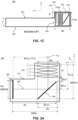
- FIG. 1C shows schematically a known mobile device 160 having an exterior rear surface 162 and including a folded Tele camera 100' in a cross-sectional view.
- An aperture 101 of camera 100' is located at rear surface 162, a front surface 166 may e.g. include a screen (not visible).
- Mobile device 160 has a regular region of thickness ("T") and a camera bump region 164 that is elevated by a height B over the regular region.
- the bump region has a bump length ("BL”) and a bump thickness T+B.
- Camera 100' includes an OPFE 102', a lens 104' with a plurality of lens elements and an image sensor 106'.
- camera 100' is entirely integrated in the bump region, so that MML and MMH define a lower limit for the bump region, i.e. for BL and T+B.
- a small camera bump i.e. a short BL
- T+B bump thickness
- a folded camera such as 100 one can realize larger BFL, larger TTL and, as a result, larger EFL corresponding to larger image zoom factors, which is desired.
- a large TTL goes along with a large BL, which is undesired.
- f/# EFUDA.
- the entrance pupil is the optical image of the aperture stop, as 'seen' through the front aperture of the lens system.
- the front aperture is the object-sided aperture of the lens.
- a low f/# is desired as it has 3 major advantages: good low light sensitivity, strong "natural" Bokeh effect and high image resolution, as discussed next:
- the former discloses a compact folded lens system that may be used in small form factor cameras.
- the system comprises a plurality of elements arranged along a folded optical axis, wherein the plurality of elements includes three lens elements and a light folding element.
- the light folding element (that may consist of a prism) is located between the first and second lens elements and redirects the light refracted from the first lens element from a first axis onto a second axis on which the other lens elements and a photosensor are arranged.
- the latter refers to a folded camera comprising a lens having a lens optical axis, an image sensor and a prism for folding light from a first optical path to a second optical path along the lens optical axis towards the image sensor.
- the camera has a full camera cone of vision, and the prism intersects said full camera cone of vision.
- the construction of the camera is such that it prevents double reflected stray light from reaching the image sensor.
- folded Tele cameras with large BFL/TTL ratios of 0.75 or more for providing large EFLs for large zoom factors and still supporting small camera bumps having short BL. It would also be beneficial to have folded Tele cameras comprising an OPFE which is oriented at a specific angle with respect to the lens optical axis.
- the present invention discloses various embodiments of a camera defined according to claims 1-13. Other examples, not comprised within the scope of the present invention, are also described for illustrative purposes.
- folded digital cameras comprising: a lens with N ⁇ 4 lens elements L i and having an EFL, an aperture diameter DA, a f-number f/#, a TTL and a BFL , wherein each lens element has a respective focal length f i and wherein a first lens element L 1 faces an object side and a last lens element L N faces an image side; an image sensor having a sensor diagonal (SD); and an optical path folding element (OPFE) for providing a folded optical path between an object and the image sensor, and wherein:
- folded digital cameras comprising: a lens with N ⁇ 4 lens elements L i and having an EFL, an aperture diameter DA, a f-number f/#, a TTL and a BFL , wherein each lens element has a respective focal length f i and wherein a first lens element L 1 faces an object side and a last lens element L N faces an image side; an image sensor having a sensor diagonal (SD); and an optical path folding element (OPFE) for providing a folded optical path between an object and the image sensor, wherein the lens is divided into a first lens group and a second lens group, wherein the first lens group is located at an object side of the OPFE, wherein the second lens group is located at an image side of the OPFE, wherein the EFL is in the range of 8mm ⁇ EFL ⁇ 50mm, and wherein a distance d(G1-G2) between the first and the second lens group fulfills d(G1-G2) > TTL/2.
- folded digital cameras comprising: a lens with N ⁇ 3 lens elements L i and having an EFL, an aperture diameter DA, a f-number f/#, a TTL, and a BFL, wherein each lens element has a respective focal length f i and wherein a first lens element L 1 faces an object side and a last lens element L N faces an image side; an image sensor having a SD; and an OPFE for providing a folded optical path between an object and the image sensor, wherein the lens is located at an object side of the OPFE, wherein the EFL is in the range of 8mm ⁇ EFL ⁇ 50mm, and wherein a ratio between the BFL and the TTL fulfills BFL/TTL > 0.75.
- folded digital cameras comprising: a lens with N ⁇ 4 lens elements L i and having an OA, an EFL, an aperture diameter DA, a f-number f/#, a TTL and a BFL, wherein each lens element has a respective focal length f i and wherein a first lens element L 1 faces an object side and a last lens element L N faces an image side; an image sensor having a SD; and an OPFE for providing a folded optical path between an object and the image sensor, the OPFE being oriented at an angle ⁇ with respect to the lens OA, wherein the lens is located at an object side of the OPFE, wherein 45 ⁇ ⁇ ⁇ 60 degrees, wherein the EFL is in the range of 8mm ⁇ EFL ⁇ 50mm, and wherein SD/EFL > 0.45.
- BFL/EFL > 0.7. In some examples, BFL/EFL> 0.9.
- the EFL is in the range 15mm ⁇ EFL ⁇ 40mm.
- the lens is movable relative to the OPFE and to the image sensor for focusing and for optical image stabilization (OIS).
- OIS optical image stabilization
- the lens and the OPFE are movable together relative to the image sensor for focusing and for OIS.
- DA is in the range 5mm ⁇ DA ⁇ 11mm and the f/# is in the range 2 ⁇ f/# ⁇ 6.5.
- DA is in the range 7mm ⁇ DA ⁇ 9mm and the f/# is in the range 3 ⁇ f/# ⁇ 5.5.
- the SD is in the range 3mm ⁇ SD ⁇ 10mm.
- a folded digital camera as above or below is included in a camera module having a shoulder height (SH) and a module height (MH), wherein the SH is in the range 4mm ⁇ SH ⁇ 8mm and the MH is in the range 6mm ⁇ MH ⁇ 12mm. In some examples, 4.5mm ⁇ SH ⁇ 6mm and the MH is in the range 7mm ⁇ MH ⁇ 9mm.
- a ratio of the distance ⁇ LO between the last surface of L N and the OPFE and the TTL fulfills ⁇ LO/TTL ⁇ 0.01.
- a ratio between an average lens thickness (ALT) of all lens elements L 1 -L i and the TTL fulfills ALT/TTL ⁇ 0.05.
- a ratio between an average gap thickness (AGT) between all lens elements L 1 -L i which are located on top of the lens and the TTL fulfills AGT/ TTL ⁇ 0.01.
- a distance d 34 between L 3 and L 4 fulfills d 34 /ALT > 2, wherein ALT is an average lens thickness of all lens elements L 1 -L i which are located on an object side of the OPFE.
- L 1 is made of glass.
- a ratio between f 1 of L 1 and the EFL fulfills f1/EFL >0.4.
- a ratio between f 1 of L 1 and the EFL fulfills f1/EFL >0.5.
- the last lens which is located on an object side of the OPFE is negative.
- a ratio of a distance d 23 between L 2 and L 3 and a lens thickness LT fulfills d 23 /LT ⁇ 0.1. In some examples, d 23 /LT ⁇ 0.05.
- a center thickness T 1 of L 1 is larger than a center thickness T i of any of the other lens elements L i .
- a ratio between T 1 and the ALT of all lens elements L 1 -L i fulfills T 1 /ALT>1.5. In some examples, Ti/ALT>1.75.
- an edge thickness ET 1 of L 1 is smaller than an edge thickness ET j of a lens element L j with the largest edge thickness of all lens elements that are located at an object side of the OPFE.
- the lens is a cut lens cut along an axis parallel to a normal on the image sensor.
- the lens may be cut by 20% relative to an axial symmetric lens diameter and the MH may be reduced by >10% by the cutting relative to an axial symmetric lens having a same lens diameter measured along an axis which is perpendicular to the normal on the image sensor and the optical axis of the lens.
- a mobile device including a camera as above or below, the mobile device having a device thickness T and a camera bump with a bump height B, wherein the bump region has an elevated height T+B, wherein the camera is fully incorporated into the camera bump region.
- the mobile device is a smartphone.
- Tables 1-12 are provided at the end of the detailed description as support for the characterization of the different embodiments.
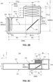
- FIG. 2A shows schematically an embodiment of a folded Tele camera disclosed herein and numbered 200.
- Camera 200 further comprises an OPFE 204 that folds OP 212 to OP 208 and an image sensor 206.
- the camera elements may be included in a housing 214, as shown.
- OP 212 is substantially parallel to the y-axis and OP 208 is substantially parallel to the z-axis.
- OPFE 204 forms an angle of 45 degrees with both the y-axis and the z-axis.
- camera 200 may have larger TTL and BFL.
- a larger TTL is beneficial for achieving a Tele camera with a large EFL and thus a high zoom factor (ZF), or image magnification factor as known in the art.
- ZF zoom factor
- a Tele camera's ZF is defined with respect to a (vertical or upright) Wide camera such as Wide camera 130 that is included in a multi-camera alongside the Tele camera.
- Lens 202 is located at an object side of OPFE 204. Therefore, both the TTL and the BFL of camera 200 are oriented not along one dimension, but along two dimensions.
- a first part TTL 1 and BFL 1 is parallel to OP 212, and a second part TTL 2 and BFL 2 is parallel to OP 208.
- lens 202 being located at an object side of OPFE 204 is that a large aperture diameter ("DA") can be achieved. This is because, opposite to a known folded camera such as 100, the optical power of lens 202 concentrates the light before it impinges on OPFE 204, not after it impinges on an OPFE.
- DA aperture diameter
- “Concentrating the light” means here that a first circle which is oriented perpendicular to the optical axis of the lens and includes all light rays that form an image at the image sensor, the first circle being located at an object side of the lens, is smaller than a second circle which is oriented perpendicular to the optical axis of the lens and includes all light rays that form an image at the image sensor, the second circle being located at an image side of the lens and at an object side of the OPFE. Therefore, given a size of an OPFE such as OPFE 102 or OPFE 204, compared to known camera 100, in camera 200 a larger DA (and thus lower f/#) can be achieved.
- An optical lens system such as optical lens systems 310, 320 and 330 may be included in camera 200.
- FIG. 2B shows schematically another embodiment of a folded Tele camera disclosed herein and numbered 220.
- N N lens elements
- TTL 1 is parallel to OP 212
- TTL 2 is parallel to OP 208
- TTL TTL 1 + TTL 2 .
- BFL is not divided into two perpendicular components. All further components of camera 220 are identical with the ones in camera 200.
- an optical element such as an IR filter may be located between OPFE 204 and G2 202-2. In other embodiments, an optical element may be located between G2 202-2 and image sensor 206.
- An optical lens system such as optical lens system 300 may be included in camera 220.
- FIG. 2C shows schematically a mobile device 230 (e.g. a smartphone) with dimensions as described in FIG. 1C having an exterior surface 232 and including a folded Tele camera 200 as disclosed herein in a cross-sectional view.
- a camera bump region is marked 234.
- a front surface 236 may e.g. include a screen (not visible).
- R1 of camera 200 is integrated into 234 of height T+B, while R2 of camera 200 is integrated into the regular device region of height T.
- mobile device 230 where camera 200 is integrated in the bump region only partially, can have a smaller BL, what is beneficial for industrial design reasons.
- another folded Tele camera such as folded Tele camera 220 as disclosed herein may be included in mobile device 230.
- mobile device 230 In general and for slim mobile devices, it is beneficial to minimize MMH1 and MMH2. Especially minimizing MMH1 is of interest, as it allows minimizing B. For compact camera, also minimizing MML is beneficial. Especially minimizing R1 is of interest, as it allows minimizing BL.
- FIG. 2D shows schematically an embodiment of a folded Tele camera disclosed herein and numbered 240.
- Camera 240 further comprises an OPFE 204 that folds OP 212 to OP 208 and an image sensor 206.
- the camera elements may be included in a housing 214, as shown.
- OP 212 is substantially parallel to the y-axis.
- OP 208 forms an angle ⁇ with the z-axis, so to OP 208 it is referred to as a "sloped OP".
- OPFE 204 forms an angle ⁇ of ⁇ >45 degrees with the y-axis and an angle 90- ⁇ ⁇ 45 degrees with the z-axis.
- sensor 206 forms an angle of 2 ⁇ ( ⁇ -45) with the y-axis.
- MML Minimum module length
- optical lens system such as optical lens system 340 may be included in camera 240.
- FIG. 2E shows schematically a mobile device 250 (e.g. a smartphone) with dimensions and components as described in FIG. 1C and FIG. 2C including a folded Tele camera 240 as disclosed herein in a cross-sectional view. Camera 240 is fully integrated into camera bump 234.
- a mobile device 250 e.g. a smartphone
- Tele camera 240 as disclosed herein in a cross-sectional view.
- Camera 240 is fully integrated into camera bump 234.
- FIG. 2F shows schematically another mobile device 260 with dimensions and components as described in FIG. 1C , FIG. 2C , FIG. 2D and FIG. 2E including a folded Tele camera 240 as disclosed herein in a cross-sectional view.
- Camera 240 is fully integrated into camera bump 234.
- OP 208 is a sloped OP that forms an angle ⁇ with the z-axis.
- the lens elements of lens 202 are carried by lens barrel 218.
- FIG. 2G shows an embodiment of a first autofocus (AF) and optical image stabilization (OIS) mechanism disclosed herein for camera 200 and camera 240.
- Lens 202 is shown in a same orientation as in FIGS. 2A-F .
- Lens 202 is moved relative to the OPFE and to the image sensor (both not shown) along an axis parallel to the y-axis for AF, along a first OIS axis ("OIS1") parallel to the z-axis for OIS along a first axis, and along a second OIS axis ("OIS2”) parallel to the x-axis for OIS along a second axis.
- Lens 202 is moved as one unit, i.e. the distances between the N lens elements (here L 1 - L 4 ) do not change, but the distances to the OPFE and to the image sensor do change (both not shown).
- FIG. 2H shows another embodiment of a second AF and OIS mechanism disclosed herein for camera 200.
- Lens 202 and OPFE 204 are shown in a same orientation as in FIGS. 2A-F .
- Lens 202 and OPFE 204 are moved as one unit relative to the image sensor (not shown) along an axis parallel to the z-axis for AF, and along a first OIS axis ("OIS1") parallel to the y-axis for OIS along a first axis, and along a second OIS axis ("OIS2”) parallel to the x-axis for OIS along a second axis.
- Moving lens 202 and OPFE 204 as one unit means that the distances between the N lens elements (here L 1 - L 4 ) and between lens 202 and OPFE 204 do not change. Only the distance to the image sensor (not shown) changes.
- FIG. 2I shows yet another embodiment of a third AF and OIS mechanism disclosed herein for camera 200.
- Lens 202 and OPFE 204 are shown in a same orientation as in FIGS. 2A-F .
- Lens 202 is moved relative to the OPFE and to the image sensor (not shown) along a first OIS axis ("OIS1") parallel to the z-axis for OIS along a first axis, and along a second OIS axis ("OIS2”) parallel to the x-axis for OIS along a second axis.
- OIS1 OIS axis
- OIS2 second OIS axis
- Lens 202 and OPFE 204 are moved as one unit relative to the image sensor (not shown) along an axis parallel to the z-axis.
- OPFE 204 must be slightly larger along the X-Z plane so that rays passing lens 202 at all possible OIS positions still incident on OPFE 204 and can contribute to an image formed at the image sensor.
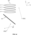
- FIG. 2J shows an embodiment of a second AF and OIS mechanism described herein for camera 240.
- Lens 202 and OPFE 204 are shown in a same orientation as in FIGS. 2D-2F , but the shown coordinate system has a different orientation.
- the coordinate system is rotated (around the x-axis) so that its z-axis is substantially parallel to OP 208.
- Lens 202 and OPFE 204 are moved as one unit relative to the image sensor (not shown) along an axis parallel to the z-axis for AF, and along a first OIS axis ("OIS1") parallel to the y-axis for OIS along a first axis, and along a second OIS axis ("OIS2") parallel to the x-axis for OIS along a second axis.
- Moving lens 202 and OPFE 204 as one unit means that the distances between the N lens elements (here L 1 - L 4 ) and between lens 202 and OPFE 204 do not change. Only the distance to the image sensor (not shown) changes.
- the differences between the embodiment of a second AF and OIS mechanism for camera 200 (see FIG. 2H ) and the embodiment of a second AF and OIS mechanism for camera 240 (see FIG. 2J ) are based on the following.
- For performing AF the motion of the image plane must be perpendicular to the image sensor plane. This is achieved by moving lens 202 and OPFE 204 together relative to the image sensor along an axis perpendicular to the image sensor plane.
- the motion of the image plane must be parallel to the image sensor plane. This is achieved by moving lens 202 and OPFE 204 together relative to the image sensor along an axis parallel to the image sensor plane.
- FIG. 2K shows an embodiment of a third AF and OIS mechanism disclosed herein for camera 240.
- Lens 202 and OPFE 204 are shown in a same orientation as in FIGS. 2A-F .
- the movement is performed with respect to coordinate system 270 which has the same orientation as the coordinate systems shown in FIGS. 2A-F .
- coordinate system 272 which the same orientation as the coordinate system shown in FIG. 2J .
- lens 202 is moved relative to the OPFE and to the image sensor (not shown) along a first OIS axis ("OIS1") parallel to the z-axis (of coordinate system 270 ) for OIS along a first axis, and along a second OIS axis ("OIS2") parallel to the x-axis (of coordinate system 270 ) for OIS along a second axis.
- OIS1 OIS axis
- OIS2 second OIS axis
- lens 202 and OPFE 204 are moved as one unit relative to the image sensor (not shown) along an axis parallel to the z-axis of coordinate system 272. It is noted that only a slight movement along the y-axis of coordinate system 270 is associated to performing AF and OIS according to the third AF and OIS mechanism.
- FIGS. 3A-3D illustrate optical lens systems disclosed herein. All lens systems shown in FIG. 3A-3D can be included in a folded camera such as shown in FIGS. 2A-C and FIGS. 2G-H .
- Table 1 summarizes values and ratios thereof of various features that are included in the lens systems shown in FIGS. 3A-3D (WLnn, WLo, LT, W OPFE-ON , W OPFE-OFF , HS, SD, ⁇ LO, R1, R2, TTL 1 , BFL 1 , TTL 2 , TTL, BFL, EFL, DA, ALT, AGT, d 23 , f 1 , T 1 , ET 1 , ET i , MML, ML, MMH1 ON , MMH1 OFF , MH ON , MH OFF , MMH2, SH, B min-ON , B min-OFF given in mm, HFOV given in degrees). Definitions and units as given here are valid also for Table 12.
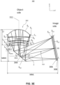
- FIG. 3A shows schematically an embodiment of an optical lens system disclosed herein and numbered 300.
- Lens system 300 comprises a lens 302, a mirror 304, an optical element 306 and an image sensor 308.
- System 300 is shown with ray tracing.
- Optical element 306 is optional and may be for example an infra-red (IR) filter, and/or a glass image sensor dust cover.
- Lens 302 is divided in two lens groups, 302-1 that includes L 1 - L 3 ("G1"), and 302-2 that includes L 4 ("G2").
- Mirror 304 is oriented at an angle of 45 degrees with respect to the y-axis and the z-axis.
- Optical rays pass through 302-1, are reflected by mirror 304, pass through 302-2 and form an image on image sensor 308.
- FIG. 3A shows 5 fields with 5 rays for each.
- Lens 302 includes a plurality of N lens elements L i (wherein "i" is an integer between 1 and N).
- L 1 is the lens element closest to the object side and L N is the lens element closest to the image side, i.e. the side where the image sensor is located. This order holds for all lenses and lens elements disclosed herein.
- the N lens elements are axial-symmetric along an optical (lens) axis 311.
- Each lens element L i comprises a respective front surface S 2i-1 (the index “2i-1” being the number of the front surface) and a respective rear surface S 2i (the index “2i” being the number of the rear surface), where "i” is an integer between 1 and N. This numbering convention is used throughout the description.
- lens surfaces are marked as “S k ", with k running from 1 to 2N.
- the front surface and the rear surface can be in some cases aspherical. This is however not limiting.
- front surface of each lens element refers to the surface of a lens element located closer to the entrance of the camera (camera object side) and the term “rear surface” refers to the surface of a lens element located closer to the image sensor (camera image side).
- lens group 302-2 is considered being a part of image sensor 308, in a sense that it does not perform any lens movements. Explicitly, this is explained in the following three paragraphs.
- d(G1-G2), 3.97mm
- d(G1-G2) 2 27.02mm
- d(G1-G2) 30.99mm
- d(G1-G2)/TTL 0.93.
- the last lens element L 4 is located at an image side of optical element 306 and at an object side of image sensor 308. In other embodiments (not shown), L 4 may be located at an object side of both optical element 306 and image sensor 308.
- the last lens element L 4 is located right next to image sensor 308, i.e. a distance (or thickness) of from L 4 to image sensor 308 is zero (Thickness 12 in Table 2). In other embodiments (not shown), L 4 may be located farther away from image sensor 308, e.g. L 4 may be located at a distance of 0.05mm to 5mm from image sensor 308.
- a power sequence of lens elements L 1 - L 4 is plus-plus-minus-plus.
- L 1 , L 2 as well as L 2 , L 3 are very close to each other.
- a pair of consecutive lens elements L i , L i+1 is "very close to each other", if a closest gap (or distance) "Gap i " between L i and L i+1 and measured along the y-axis is Gap i ⁇ 0.1mm at some position between optical axis 311 and the diameter radius of L i or L i+1 .
- Gap 1 0.03mm (between L 1 and L 2 )
- Gap 2 0.03mm (between L 2 and L 3 ).
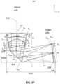
- FIG. 3B shows schematically another embodiment of an optical lens system disclosed herein and numbered 310.
- Lens system 310 comprises a lens 312, a mirror 314, an optical element 306 and an image sensor 308.
- Lens 312 includes 5 lens elements numbered L 1 - L 5 .
- a power sequence of lens elements L 1 - L 5 is plus-minus-minus-plus-minus.
- FIG. 3C shows schematically yet another embodiment of an optical lens system disclosed herein and numbered 320.
- Lens system 320 comprises a lens 322, a mirror 324, an optical element 306 and an image sensor 308.
- Lens 322 includes 3 lens elements numbered L 1 - L 3 .
- a power sequence of lens elements L 1 - L 3 is plus-minus-minus.
- FIG. 3D shows schematically yet another embodiment of an optical lens system disclosed herein and numbered 330.
- Lens system 330 comprises a lens 332, a mirror 334, an optical element 306 and an image sensor 308.
- Lens 332 includes 3 lens elements numbered L 1 - L 3 .
- a power sequence of lens elements L 1 - L 3 is plus-minus-minus.
- Lens 332 is obtained by cutting the width of the lens elements of lens 322 by 20%. For details on lens elements included in lens 332, it is referred to Table 6 and Table 7. The cutting is performed along a direction parallel to the lens optical axis (i.e.
- WLz a width of lens WL measured along a z-direction
- WLx a WL measured along a x-direction
- the cutting of lens 332 translates to significant savings in terms of module height (MH), which is beneficial for slim mobile device design: MMH ON and MMH1 OFF are reduced from 8.6mm to 7.24mm and from 9.01mm to 7.54mm respectively. MH ON is reduced from 10.1mm to 8.74mm (about 16% reduction). The cutting of lens 332 by 20% translates into camera module height savings of about 15-20%.
- lens system 330 there are no significant savings in terms of module length (ML).
- ML module length
- the lens optimization on the smaller vertical (i.e. along a y-axis) image region shifts the optimal focus distance to higher z-values, diminishing the reduction of the cutting in z-direction.
- FIG. 3E shows schematically an embodiment of an optical lens system disclosed herein and numbered 340.
- Lens system 340 can be included in a folded camera with sloped OP such as shown in FIGS. 2D-F .
- Lens system 340 comprises a lens 342, a mirror 344, an optical element 306 (optional) and an image sensor 308.
- Lens 342 includes 4 lens elements numbered L 1 - L 4 .
- the coefficients for the surfaces are defined in Table 8.
- the coefficients for the surfaces are defined in Table 9.
- the semi-diameter (D/2) of mirror 344 is defined by a circle that fully incorporates it.
- a length of mirror 344 measured in the yz-mirror-plane is 4.2mm, its width (measured along the x-axis, not shown here) is 6mm.
- the tilting angle ⁇ of mirror 344 with respect to the z-axis is 51 degrees.
- OP 313 is not parallel to the z-axis, but forms an angle ⁇ with the z-axis.
- Both L 3 and L 4 have a lens surface that has two or more deflection points.
- a power sequence of lens elements L 1 - L 4 is plus-minus-plus-minus.
- Gap i /LT ⁇ 0.015 is fulfilled.
- lens 342 may be a cut to achieve a cut lens based on lens 342.
- the cut lens may be obtained by cutting the width of lens elements of lens 342 by 10% - 40%.
- the cutting is of the width is performed along a direction parallel to the lens optical axis (i.e. parallel to the y-axis), so that a width of lens WL measured along a y-direction ("WL Y ") is smaller than in a WL measured along a x-direction ("WL X "), i.e. WL Y ⁇ WL X (see FIG. 7 ).
- FIG. 3F shows schematically another embodiment of an optical lens system disclosed herein and numbered 350.
- Lens system 350 can be included in a folded camera with sloped OP such as shown in FIGS. 2D-F .
- Lens system 350 comprises a lens 352, a mirror 354, an optical element 306 (optional) and an image sensor 308.
- Lens 352 includes 4 lens elements numbered L 1 - L 4 .
- the coefficients for the surfaces are defined in Table 10.
- the coefficients for the surfaces are defined in Table 11.
- the semi-diameter (D/2) of mirror 354 is defined by a circle that fully incorporates it.
- a length of mirror 354 measured in the yz-mirror-plane is 5.2mm, its width (measured along the x-axis, not shown here) is 5.6mm.
- the tilting angle ⁇ of mirror 354 with respect to the z-axis is 48.2 degrees.
- OP 313 is not parallel to the z-axis, but forms an angle ⁇ with the z-axis.
- Both L 3 and L 4 have a lens surface that has two or more deflection points. Lens element pairs L 1 , L 2 and L 2 , L 3 of lens 350 are very close to each other.
- Gap 1 /LT ⁇ 0.015 and Gap 2 /LT ⁇ 0.015 is fulfilled.
- at least one of the GAP i s is located not at a center of the lens elements.
- a power sequence of lens elements L 1 - L 4 is plus-minus-plus-plus.
- lens 352 may be cut to achieve a cut lens based on lens 352.
- the cut lens may be obtained by cutting the width of lens elements of lens 352 by 10% - 40%.
- the cutting is of the width is performed along a direction parallel to the y-axis, so that a width of lens WL measured along a y-direction ("WL Y ") is smaller than in a WL measured along a x-direction ("WL X "), i.e. WL Y ⁇ WL X (see FIG. 7 ).
- MH may be reduced by about 7.5%-20% and MMH may be reduced by about 10%-20%.
- a lens optical axis is perpendicular to a normal on an image sensor, in contrast to exemplary optical lens systems as see below, where a lens optical axis is parallel to a normal on an image sensor.
- a clear height value CH(S k ) can be defined for each surface S k for 1 ⁇ k ⁇ 2N), and a clear aperture value CA(S k ) can be defined for each surface S k for 1 ⁇ k ⁇ 2N).
- CA(S k ) and CH(S k ) define optical properties of each surface S k of each lens element.
- the CH term is defined with reference to FIG. 5A and the CA term is defined with reference to FIG. 5B , below.
- a height (“H Li ", for 1 ⁇ i ⁇ N) is defined for each lens element L i .
- H Li corresponds, for each lens element L i , to the maximal height of lens element L i measured along an axis perpendicular to the optical axis of the lens elements. For a given lens element, the height is greater than, or equal to the clear height value CH and the clear aperture value CA of the front and rear surfaces of this given lens element.
- H Li is the diameter of lens element L i as seen in FIG. 6 .
- H Li max ⁇ CA(S 2i-1 ), CA(S 2i ) ⁇ + a mechanical part size. In general, in lens design the mechanical part size is defined as not contributing to the optical properties of the lens. Because of this, one defines ( FIG.
- an optical height H opt (corresponding to the CA value) of an optically active area 602 and a geometrical (or mechanical) height of the lens H L of an entire lens area 604 that covers an optically active and an optically inactive area.
- the mechanical part and its properties are defined below.
- the mechanical part size contribution to H Li is typically 200-1000 ⁇ m.
- each optical ray that passes through a surface S k (for 1 ⁇ k ⁇ 2N) impinges this surface on an impact point IP.
- Optical rays enter camera 200 or 220 from surface S 1 and pass through surfaces S 2 to S 2N .
- Some optical rays can impinge on any surface S k but cannot /will not reach image sensor 206.
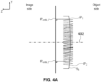
- CH(S k ) is defined as the distance between two closest possible parallel lines (see lines 500 and 502 in FIG. 5A located on a plane P orthogonal to the optical axis of the lens elements.
- plane P is parallel to plane X-Y and is orthogonal to optical axis 402 such that the orthogonal projection IP orth of all impact points IP on plane P is located between the two parallel lines.
- CH(S k ) can be defined for each surface S k (front and rear surfaces, with 1 ⁇ k ⁇ 2N).
- CH(S k ) does not depend on the object currently imaged, since it refers to the optical rays that "can” form an image on the image sensor. Thus, even if the currently imaged object is located in a black background that does not produce light, the definition does not refer to this black background since it refers to any optical rays that "can” reach the image sensor to form an image (for example optical rays emitted by a background that would emit light, contrary to a black background).
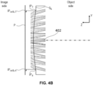
- FIG. 4A illustrates the orthogonal projections IP orth,1 , IP orth,2 of two impact points IP 1 and IP 2 on plane P that is orthogonal to optical axis 402 .
- surface S k is convex.
- FIG. 4B illustrates the orthogonal projections IP orth,3 , IP orth,4 of two impact points IP 3 and IP 4 on plane P
- surface S k is concave.
- the orthogonal projection IP orth of all impact points IP of a surface S k on plane P is located between parallel lines 500 and 502.
- CH(S k ) is thus the distance between lines 500 and 502.
- a clear aperture CA(S k ) is defined for each given surface S k (for 1 ⁇ k ⁇ 2N), as the diameter of a circle, wherein the circle is the smallest possible circle located in a plane P orthogonal to the optical axis 402 and encircling all orthogonal projections IP orth of all impact points on plane P.
- the definition of CA(S k ) also does not depend on the object that is currently imaged.
- the circumscribed orthogonal projection IP orth of all impact points IP on plane P is a circle 510.
- the diameter of circle 510 defines CA(S k ).
- FIG. 7 shows a lens barrel 700 that includes a plurality of cut lens elements and a lens housing 704.
- a first cut lens element L 1 702 is visible.
- L 1 has a width along the x-axis ("WLx") that is larger than the width along the z-axis ("WLz”), i.e. WL X > WLz.
- the x-axis and the z-axis are oriented identical as in FIG. 2A and FIG. 2B .
- Table 1 300 300 310 320 330 MIN value MAX value WL M 8.12 8.42 8.26 6.40 6.40 8.42 WL O 8.02 8.32 8.16 6.40 6.40 8.32 LT 1.66 3.05 1.50 1.50 1.50 3.05 W OPFE-ON 7.11 7.30 7.17 5.74 5.74 7.30 W OPFE-OFF 7.46 7.65 7.57 6.04 6.04 7.65 HS 3.36 3.36 3.36 3.36 3.36 SD 5.6 5.6 5.6 5.6 5.6 5.6 ⁇ LO 0.001 0.03 0.07 0.07 0.00 0.07 R1 8.12 8.42 8.26 6.40 6.40 8.42 R2 23.72 29.70 22.21 24.08 22.21 29.70 TTL 1 5.63 7.08 5.57 4.70 4.70 7.08 BFL 1 0 4.03 4.07 3.20 3.20 4.07 TTL 2 27.78 33.90 26.33 27
Landscapes
- Physics & Mathematics (AREA)
- General Physics & Mathematics (AREA)
- Optics & Photonics (AREA)
- Engineering & Computer Science (AREA)
- Multimedia (AREA)
- Signal Processing (AREA)
- Lenses (AREA)
- Studio Devices (AREA)
- Cameras In General (AREA)
- Structure And Mechanism Of Cameras (AREA)
- Adjustment Of Camera Lenses (AREA)
Applications Claiming Priority (6)
| Application Number | Priority Date | Filing Date | Title |
|---|---|---|---|
| US202163213899P | 2021-06-23 | 2021-06-23 | |
| US202163245892P | 2021-09-19 | 2021-09-19 | |
| US202163288047P | 2021-12-10 | 2021-12-10 | |
| US202163291628P | 2021-12-20 | 2021-12-20 | |
| EP22827795.0A EP4360327A4 (de) | 2022-06-21 | Kompakte gefaltete fernsehkameras | |
| PCT/IB2022/055745 WO2022269486A1 (en) | 2021-06-23 | 2022-06-21 | Compact folded tele cameras |
Related Parent Applications (1)
| Application Number | Title | Priority Date | Filing Date |
|---|---|---|---|
| EP22827795.0A Division EP4360327A4 (de) | 2021-06-23 | 2022-06-21 | Kompakte gefaltete fernsehkameras |
Publications (2)
| Publication Number | Publication Date |
|---|---|
| EP4425233A2 true EP4425233A2 (de) | 2024-09-04 |
| EP4425233A3 EP4425233A3 (de) | 2024-11-13 |
Family
ID=84545480
Family Applications (3)
| Application Number | Title | Priority Date | Filing Date |
|---|---|---|---|
| EP25213096.8A Pending EP4664177A3 (de) | 2021-06-23 | 2022-06-21 | Kompakte gefaltete fernsehkameras |
| EP24189431.0A Pending EP4425234A3 (de) | 2021-06-23 | 2022-06-21 | Kompakte gefaltete fernsehkameras |
| EP24189430.2A Pending EP4425233A3 (de) | 2021-06-23 | 2022-06-21 | Kompakte gefaltete fernsehkameras |
Family Applications Before (2)
| Application Number | Title | Priority Date | Filing Date |
|---|---|---|---|
| EP25213096.8A Pending EP4664177A3 (de) | 2021-06-23 | 2022-06-21 | Kompakte gefaltete fernsehkameras |
| EP24189431.0A Pending EP4425234A3 (de) | 2021-06-23 | 2022-06-21 | Kompakte gefaltete fernsehkameras |
Country Status (7)
| Country | Link |
|---|---|
| US (2) | US12228709B2 (de) |
| EP (3) | EP4664177A3 (de) |
| JP (1) | JP2024524206A (de) |
| KR (2) | KR20240012438A (de) |
| CN (1) | CN121386146A (de) |
| TW (2) | TWI896890B (de) |
| WO (1) | WO2022269486A1 (de) |
Families Citing this family (6)
| Publication number | Priority date | Publication date | Assignee | Title |
|---|---|---|---|---|
| WO2023075347A1 (ko) * | 2021-10-25 | 2023-05-04 | 삼성전자 주식회사 | 카메라 모듈 및 이를 포함하는 전자 장치 |
| CN119278398A (zh) | 2022-05-26 | 2025-01-07 | 三星电子株式会社 | 镜头组件和包括该镜头组件的电子设备 |
| US20230388616A1 (en) * | 2022-05-26 | 2023-11-30 | Samsung Electronics Co., Ltd. | Image-capturing device and electronic device including same |
| KR102869964B1 (ko) * | 2023-11-08 | 2025-10-14 | 코어포토닉스 리미티드 | 슬림형 고화질 광학 이미지 안정화 액추에이터를 갖는 컴팩트 폴디드 텔레 카메라 |
| KR20250071764A (ko) * | 2023-11-15 | 2025-05-22 | 자화전자(주) | 광 굴절 요소가 af 구동되는 선두렌즈 타입 폴디드 액추에이터 및 이 액추에이터를 포함하는 카메라 |
| WO2026028198A1 (en) * | 2024-08-01 | 2026-02-05 | Corephotonics Ltd | Mobile folded tele cameras with uniform image contrast on large image sensors |
Citations (2)
| Publication number | Priority date | Publication date | Assignee | Title |
|---|---|---|---|---|
| US20170276914A1 (en) | 2016-03-28 | 2017-09-28 | Apple Inc. | Folded lens system with three refractive lenses |
| US20210048649A1 (en) | 2017-07-07 | 2021-02-18 | Corephotonics Ltd. | Folded camera prism design for preventing stray light |
Family Cites Families (340)
| Publication number | Priority date | Publication date | Assignee | Title |
|---|---|---|---|---|
| US2106752A (en) | 1934-12-03 | 1938-02-01 | Sheet Polarizer Company Inc | Field divider |
| US2354503A (en) | 1941-12-01 | 1944-07-25 | Taylor Taylor & Hobson Ltd | Optical objective of the telephoto type |
| US2378170A (en) | 1943-06-25 | 1945-06-12 | Eastman Kodak Co | Telephoto lens |
| US2441093A (en) | 1946-07-22 | 1948-05-04 | Eastman Kodak Co | Telephoto lens |
| US3388956A (en) | 1963-04-10 | 1968-06-18 | Voigtlaender Ag | Photographic telephoto lenses of high telephoto power |
| DE1447278A1 (de) | 1964-06-20 | 1968-12-19 | Voigtlaender Ag | Tele-Anastigmat mittlerer Lichtstaerke mit grossem Telephoto-Effekt |
| US3558218A (en) | 1967-12-01 | 1971-01-26 | Polaroid Corp | Three-element telephoto objective lens |
| JPS5116135B2 (de) | 1972-05-10 | 1976-05-21 | ||
| US3942876A (en) | 1972-09-07 | 1976-03-09 | Ponder & Best, Inc. | Telephoto lens |
| JPS5327421A (en) | 1976-08-26 | 1978-03-14 | Asahi Optical Co Ltd | Small telephotographic lens |
| JPS54157620A (en) | 1978-06-01 | 1979-12-12 | Konishiroku Photo Ind Co Ltd | Photographic telephoto lens |
| JPS55163510A (en) | 1979-06-06 | 1980-12-19 | Nippon Kogaku Kk <Nikon> | Telephoto lens |
| JPS5850509A (ja) | 1981-09-21 | 1983-03-25 | Ricoh Co Ltd | 小型望遠レンズ |
| JPS59121015A (ja) | 1982-12-28 | 1984-07-12 | Nippon Kogaku Kk <Nikon> | 近距離補正された写真レンズ |
| JPS6165212A (ja) | 1984-09-07 | 1986-04-03 | Fuji Xerox Co Ltd | 複写機の結像レンズ |
| JPS6370211A (ja) | 1986-09-11 | 1988-03-30 | Canon Inc | プラスチツク製光学素子 |
| JPH0690350B2 (ja) | 1986-12-15 | 1994-11-14 | 富士写真光機株式会社 | カメラ |
| JPH0233117A (ja) | 1988-07-22 | 1990-02-02 | Ricoh Co Ltd | レンズ光軸調整装置 |
| US5000551A (en) | 1989-06-05 | 1991-03-19 | Nikon Corporation | Zoom lens |
| JP3103166B2 (ja) | 1991-11-26 | 2000-10-23 | 富士写真光機株式会社 | 射出瞳の遠いマクロレンズ |
| US5327291A (en) | 1992-03-30 | 1994-07-05 | Polaroid Corporation | Compact objective lens |
| JPH0659195A (ja) | 1992-08-07 | 1994-03-04 | Fuji Photo Optical Co Ltd | 内視鏡用光学系装置 |
| JP3181747B2 (ja) | 1993-03-02 | 2001-07-03 | オリンパス光学工業株式会社 | カメラ |
| JPH06347687A (ja) | 1993-06-07 | 1994-12-22 | Nikon Corp | ズーム式レンズ鏡筒 |
| JPH07120673A (ja) | 1993-10-21 | 1995-05-12 | Ricoh Co Ltd | コンパクトなズームレンズ |
| JP3358639B2 (ja) | 1994-05-31 | 2002-12-24 | 京セラ株式会社 | カメラのフォーカス制御方式 |
| JPH07333505A (ja) | 1994-06-10 | 1995-12-22 | Canon Inc | 撮像装置 |
| JP3445404B2 (ja) | 1994-08-12 | 2003-09-08 | ペンタックス株式会社 | 投影レンズ及び投影装置 |
| JP3412939B2 (ja) | 1994-12-22 | 2003-06-03 | キヤノン株式会社 | ズームレンズ |
| JP3210242B2 (ja) | 1995-03-06 | 2001-09-17 | 川崎製鉄株式会社 | 黒鉛含有不定形耐火物 |
| JP3851677B2 (ja) | 1996-02-06 | 2006-11-29 | オリンパス株式会社 | ズームレンズ |
| DE69715198T3 (de) * | 1996-06-18 | 2009-07-09 | Corp. Sony | Optisches bildaufnahmesystem und dazugehörige entwicklungsvorrichtung |
| JP3676524B2 (ja) | 1996-10-25 | 2005-07-27 | ペンタックス株式会社 | プリズム |
| JPH1195105A (ja) | 1997-07-22 | 1999-04-09 | Nikon Corp | 変倍光学系の合焦方式 |
| JP3811281B2 (ja) | 1997-12-10 | 2006-08-16 | オリンパス株式会社 | ズームレンズ鏡筒 |
| JPH11223771A (ja) | 1998-02-06 | 1999-08-17 | Nikon Corp | 可変焦点距離レンズ系 |
| US6147702A (en) | 1998-04-17 | 2000-11-14 | Intel Corporation | Calibration of digital cameras |
| JP3570253B2 (ja) | 1998-10-28 | 2004-09-29 | ソニー株式会社 | ズームレンズ |
| JP2000292848A (ja) | 1999-04-06 | 2000-10-20 | Fuji Photo Film Co Ltd | 光学機器 |
| US6195209B1 (en) | 1999-05-04 | 2001-02-27 | U.S. Precision Lens Incorporated | Projection lenses having reduced lateral color for use with pixelized panels |
| JP3201394B2 (ja) * | 1999-08-10 | 2001-08-20 | 住友電気工業株式会社 | fθレンズ |
| JP2002131639A (ja) * | 2000-10-20 | 2002-05-09 | Nikon Corp | ズームレンズ及びこのレンズを備える投射型表示装置 |
| JP4278879B2 (ja) | 2001-02-27 | 2009-06-17 | 株式会社オートネットワーク技術研究所 | 車両周辺視認装置 |
| JP2002365549A (ja) | 2001-06-06 | 2002-12-18 | Canon Inc | ズームレンズ及びそれを有する光学機器 |
| JP2003057546A (ja) | 2001-08-20 | 2003-02-26 | Pentax Corp | ズームレンズ系 |
| JP3503941B2 (ja) | 2002-02-04 | 2004-03-08 | 富士写真光機株式会社 | 3群ズームレンズ |
| JP4262439B2 (ja) | 2002-05-14 | 2009-05-13 | オリンパス株式会社 | ズームレンズ及びそれを有する電子撮像装置 |
| US7085070B2 (en) * | 2002-05-14 | 2006-08-01 | Olympus Corporation | Zoom lens and electronic imaging device having the same |
| JP2004170707A (ja) | 2002-11-20 | 2004-06-17 | Minolta Co Ltd | 撮像レンズ装置およびそれを備えたデジタルカメラ |
| JP2004226563A (ja) | 2003-01-21 | 2004-08-12 | Nikon Corp | 可変焦点距離レンズ系 |
| JP4191501B2 (ja) | 2003-02-13 | 2008-12-03 | 日本電産コパル株式会社 | 携帯情報端末装置 |
| CN100449268C (zh) | 2003-02-14 | 2009-01-07 | Bei传感器及系统有限公司 | 使用线性霍尔效应传感器、具有增强线性磁体配置的位置传感器 |
| JP2004334185A (ja) | 2003-04-18 | 2004-11-25 | Canon Inc | ズームレンズ |
| US6924948B2 (en) | 2003-08-21 | 2005-08-02 | Arc Design, Inc. | Multifocal lens system for digital cameras |
| JP4276914B2 (ja) | 2003-09-18 | 2009-06-10 | オリンパス株式会社 | 振動波リニアモータ及びその駆動方法 |
| JP2005134486A (ja) | 2003-10-28 | 2005-05-26 | Ricoh Co Ltd | カラー画像読取レンズ、カラー画像読取レンズユニット、カラー画像読取装置および画像形成装置 |
| JP2005173191A (ja) | 2003-12-11 | 2005-06-30 | Olympus Corp | 光路折り曲げ光学系 |
| JP2005215473A (ja) | 2004-01-30 | 2005-08-11 | Sekinosu Kk | 投影レンズ装置 |
| US6980379B1 (en) | 2004-07-19 | 2005-12-27 | Microalign Technologies, Inc. | Flat wide-angle objective |
| WO2006011610A1 (en) | 2004-07-26 | 2006-02-02 | Ricoh Company, Ltd. | Lens barrel, camera and mobile information terminal |
| JP4674889B2 (ja) * | 2004-09-28 | 2011-04-20 | オリンパス株式会社 | 電子撮像装置 |
| JP4684597B2 (ja) | 2004-08-13 | 2011-05-18 | Hoya株式会社 | レンズ制御装置 |
| JP2006154702A (ja) | 2004-10-29 | 2006-06-15 | Konica Minolta Opto Inc | 変倍光学系、撮像レンズ装置及びデジタル機器 |
| US9155483B2 (en) | 2004-12-03 | 2015-10-13 | The Invention Science Fund I, Llc | Vision modification with reflected image |
| JP4679906B2 (ja) | 2005-01-13 | 2011-05-11 | 株式会社リコー | レンズ固定構造 |
| US7206136B2 (en) | 2005-02-18 | 2007-04-17 | Eastman Kodak Company | Digital camera using multiple lenses and image sensors to provide an extended zoom range |
| JP4641203B2 (ja) | 2005-03-07 | 2011-03-02 | 株式会社リコー | レンズ鏡胴、このレンズ鏡胴を用いたカメラ及び携帯型情報端末装置 |
| JP4731977B2 (ja) | 2005-04-22 | 2011-07-27 | キヤノン株式会社 | 光学機器 |
| JP2006323219A (ja) | 2005-05-19 | 2006-11-30 | Konica Minolta Photo Imaging Inc | レンズユニット、およびそれを備えた撮像装置 |
| JP4794912B2 (ja) | 2005-06-02 | 2011-10-19 | キヤノン株式会社 | ズームレンズ及びそれを有する撮像装置 |
| JP2007133096A (ja) | 2005-11-09 | 2007-05-31 | Konica Minolta Opto Inc | 撮像光学系、撮像レンズ装置及びデジタル機器 |
| JP4903418B2 (ja) | 2005-11-18 | 2012-03-28 | イーストマン コダック カンパニー | ズームレンズ |
| JP2007164065A (ja) | 2005-12-16 | 2007-06-28 | Konica Minolta Opto Inc | レンズユニット及び撮像装置 |
| JP2007206544A (ja) | 2006-02-03 | 2007-08-16 | Matsushita Electric Ind Co Ltd | ズームレンズ系、レンズ鏡筒、撮像装置及びカメラ |
| JP2007212961A (ja) | 2006-02-13 | 2007-08-23 | Matsushita Electric Ind Co Ltd | ズームレンズ系、撮像装置及びカメラ |
| JP2007219199A (ja) | 2006-02-17 | 2007-08-30 | Konica Minolta Opto Inc | レンズユニット、撮像装置及びレンズの製造方法 |
| JP2007219316A (ja) | 2006-02-17 | 2007-08-30 | Nikon Corp | ズームレンズとこれを具備する光学装置 |
| JP4916198B2 (ja) | 2006-03-20 | 2012-04-11 | 株式会社リコー | ズームレンズ、ズームレンズを有する撮像装置、カメラ装置および携帯情報端末装置 |
| JP4905653B2 (ja) | 2006-03-28 | 2012-03-28 | ペンタックスリコーイメージング株式会社 | 中望遠レンズ系 |
| JP2007310343A (ja) | 2006-04-17 | 2007-11-29 | Sharp Corp | レンズ鏡筒およびレンズ鏡筒の組立方法およびカメラモジュール |
| JP2007306282A (ja) | 2006-05-11 | 2007-11-22 | Citizen Electronics Co Ltd | カメラモジュール |
| KR100900486B1 (ko) | 2006-09-04 | 2009-06-03 | 삼성테크윈 주식회사 | 촬상 장치용 광학 모듈 및 이를 구비한 촬상 장치 |
| JP4956343B2 (ja) | 2006-09-25 | 2012-06-20 | 富士フイルム株式会社 | 2焦点撮像光学系および撮像機器 |
| US7515345B2 (en) | 2006-10-09 | 2009-04-07 | Drs Sensors & Targeting Systems, Inc. | Compact objective lens assembly |
| KR20080032759A (ko) | 2006-10-10 | 2008-04-16 | 삼성전기주식회사 | 카메라 모듈의 렌즈배럴 및 이를 조립하는 레이져장치 |
| KR101278239B1 (ko) | 2006-10-17 | 2013-06-24 | 삼성전자주식회사 | 듀얼 렌즈 광학계 및 이를 구비하는 듀얼 렌즈 카메라 |
| JP2008102427A (ja) | 2006-10-20 | 2008-05-01 | Tamron Co Ltd | 光学装置および撮像装置 |
| JP2008111876A (ja) | 2006-10-27 | 2008-05-15 | Sony Corp | カメラモジュール |
| JP4994812B2 (ja) | 2006-12-05 | 2012-08-08 | キヤノン株式会社 | 撮像装置 |
| JP2008191423A (ja) | 2007-02-05 | 2008-08-21 | Sharp Corp | レンズユニット及びカメラモジュール、並びに該カメラモジュールを備えた撮像装置 |
| JP5000403B2 (ja) | 2007-03-28 | 2012-08-15 | 富士フイルム株式会社 | 変倍光学系および撮像装置 |
| TWI332584B (en) | 2007-04-25 | 2010-11-01 | Largan Precision Co Ltd | Optical lens system for taking image |
| US8794526B2 (en) | 2007-06-04 | 2014-08-05 | Hand Held Products, Inc. | Indicia reading terminal processing plurality of frames of image data responsively to trigger signal activation |
| JP2008304708A (ja) | 2007-06-07 | 2008-12-18 | Konica Minolta Opto Inc | ズームレンズ及び撮像装置 |
| TWI351530B (en) | 2007-07-05 | 2011-11-01 | Largan Precision Co Ltd | Inverse telephoto with correction lenses |
| TWI354820B (en) | 2007-08-14 | 2011-12-21 | Largan Precision Co Ltd | Optical lens system for taking image |
| KR100921146B1 (ko) | 2007-08-21 | 2009-10-12 | 엘지이노텍 주식회사 | 렌즈 모듈 |
| JP4947423B2 (ja) | 2007-08-29 | 2012-06-06 | コニカミノルタオプト株式会社 | 撮像レンズ |
| EP2037306A1 (de) | 2007-09-12 | 2009-03-18 | Fujinon Corporation | Abbildungslinse und Abbildungsvorrichtung |
| US7710665B2 (en) | 2007-11-08 | 2010-05-04 | Samsung Electro-Mechanics Co., Ltd. | Imaging optical system |
| TWI361914B (en) | 2007-11-16 | 2012-04-11 | Largan Precision Co Ltd | Optical lens system for taking image |
| US9118850B2 (en) | 2007-11-27 | 2015-08-25 | Capso Vision, Inc. | Camera system with multiple pixel arrays on a chip |
| JP2009134175A (ja) | 2007-11-30 | 2009-06-18 | Olympus Imaging Corp | 結像光学系 |
| JP2011509415A (ja) | 2007-12-04 | 2011-03-24 | ブラックアイ オプティクス,エルエルシー | 固定群内に液体レンズを有する望遠タイプのズームレンズ |
| KR100956250B1 (ko) | 2007-12-10 | 2010-05-06 | 삼성전기주식회사 | 웨이퍼 스케일 렌즈조립체 제조방법 및 이에 의해 제조된웨이퍼 스케일 렌즈조립체 |
| TWI354821B (en) | 2007-12-18 | 2011-12-21 | Largan Precision Co Ltd | Optical lens system for taking image |
| EP2223173B1 (de) | 2007-12-19 | 2013-09-04 | Heptagon Micro Optics Pte. Ltd. | Kameravorrichtung und herstellungsverfahren dafür |
| KR101431538B1 (ko) | 2007-12-24 | 2014-09-19 | 삼성전자주식회사 | 줌 렌즈 시스템 |
| WO2009084192A1 (ja) | 2007-12-28 | 2009-07-09 | Panasonic Corporation | レンズ鏡筒およびレンズ支持構造 |
| TWI361915B (en) | 2008-02-18 | 2012-04-11 | Largan Precision Co Ltd | Optical lens system for taking image |
| TWI361913B (en) | 2008-02-27 | 2012-04-11 | Largan Precision Co Ltd | Optical lens system for taking image |
| TWI361903B (en) | 2008-02-27 | 2012-04-11 | Largan Precision Co Ltd | Optical lens system for taking image |
| JP2009216941A (ja) | 2008-03-10 | 2009-09-24 | Tamron Co Ltd | 屈曲変倍光学系 |
| JP2009258286A (ja) | 2008-04-15 | 2009-11-05 | Konica Minolta Opto Inc | 撮像レンズ、撮像ユニット及び携帯端末 |
| CN101576642B (zh) | 2008-05-06 | 2013-04-24 | 鸿富锦精密工业(深圳)有限公司 | 间隔环以及具有该间隔环的镜头模组 |
| KR100962970B1 (ko) | 2008-06-19 | 2010-06-10 | 엘지이노텍 주식회사 | 촬상 렌즈 |
| JP5206174B2 (ja) | 2008-07-08 | 2013-06-12 | 株式会社リコー | ズームレンズおよびカメラおよび携帯情報端末装置 |
| CN101634738A (zh) | 2008-07-25 | 2010-01-27 | 鸿富锦精密工业(深圳)有限公司 | 镜头模组及相机模组 |
| TWI395992B (zh) | 2008-07-25 | 2013-05-11 | Largan Precision Co | 四片式攝影光學鏡組 |
| JP5137729B2 (ja) | 2008-07-31 | 2013-02-06 | 株式会社オプトロジック | ズームレンズ |
| JP5483842B2 (ja) | 2008-08-06 | 2014-05-07 | キヤノン株式会社 | 撮像装置 |
| JP5304117B2 (ja) | 2008-09-05 | 2013-10-02 | コニカミノルタ株式会社 | 撮像レンズ及び撮像装置並びに携帯端末 |
| US8049979B2 (en) | 2008-09-08 | 2011-11-01 | Panasonic Corporation | Lens barrel and imaging device |
| TWI384254B (zh) | 2008-10-16 | 2013-02-01 | Largan Precision Co Ltd | 取像透鏡組 |
| TWI379102B (en) | 2008-11-20 | 2012-12-11 | Largan Precision Co Ltd | Optical lens system for taking image |
| TWI388878B (zh) | 2008-12-01 | 2013-03-11 | Largan Precision Co Ltd | 取像光學鏡片組 |
| TWI382199B (zh) | 2008-12-16 | 2013-01-11 | Largan Precision Co Ltd | 攝像用透鏡組 |
| JP5201679B2 (ja) | 2008-12-25 | 2013-06-05 | 株式会社オプトロジック | 撮像レンズ |
| JP5300467B2 (ja) | 2008-12-26 | 2013-09-25 | キヤノン株式会社 | 光学系及びそれを有する光学機器 |
| US7826149B2 (en) | 2008-12-27 | 2010-11-02 | Largan Precision Co., Ltd. | Optical lens system for taking image |
| JP2010164841A (ja) | 2009-01-16 | 2010-07-29 | Sharp Corp | 撮像モジュール、撮像装置及び光学機器 |
| TWI394979B (zh) | 2009-01-22 | 2013-05-01 | Largan Precision Co Ltd | 薄型攝影光學鏡組 |
| TWI406004B (zh) | 2009-02-19 | 2013-08-21 | Largan Precision Co Ltd | 成像光學透鏡組 |
| TWI406005B (zh) | 2009-02-24 | 2013-08-21 | Asia Optical Co Inc | 小型化變焦鏡頭及影像擷取裝置 |
| US8553106B2 (en) | 2009-05-04 | 2013-10-08 | Digitaloptics Corporation | Dual lens digital zoom |
| TWI395990B (zh) | 2009-05-11 | 2013-05-11 | Largan Precision Co Ltd | 攝影用透鏡組 |
| TWI404972B (zh) | 2009-06-19 | 2013-08-11 | Largan Precision Co | 成像光學鏡組 |
| TWI401466B (zh) | 2009-06-19 | 2013-07-11 | Largan Precision Co | 二片式攝影光學鏡組 |
| KR20110002630A (ko) | 2009-07-02 | 2011-01-10 | 삼성전자주식회사 | 휴대 단말기의 카메라 운용 방법 및 장치 |
| TWI421557B (zh) | 2009-07-14 | 2014-01-01 | 大立光電股份有限公司 | 攝像透鏡系統 |
| DE102009028861B4 (de) | 2009-08-25 | 2015-03-05 | Trimble Jena Gmbh | Messvorrichtung mit verringertem Anteil an Störlicht und Herstellungsverfahren für diese |
| JP5671684B2 (ja) | 2009-08-31 | 2015-02-18 | パナソニックIpマネジメント株式会社 | レンズ鏡筒、撮像装置および携帯端末装置 |
| JP5405360B2 (ja) | 2009-10-06 | 2014-02-05 | 富士フイルム株式会社 | 撮像レンズおよび撮像装置 |
| US8248523B2 (en) | 2009-11-05 | 2012-08-21 | Flextronics Ap, Llc | Camera module with fold over flexible circuit and cavity substrate |
| US8559118B2 (en) | 2009-11-18 | 2013-10-15 | DigitalOptics Corporation Europe Limited | Fixed focal length optical lens architecture providing a customized depth of focus optical system |
| KR20110058094A (ko) | 2009-11-25 | 2011-06-01 | 삼성전기주식회사 | 렌즈조립체 및 이를 이용한 카메라 모듈 |
| JP2011128445A (ja) | 2009-12-18 | 2011-06-30 | Sony Corp | ズームレンズ及び撮像装置 |
| JP2011138047A (ja) | 2009-12-28 | 2011-07-14 | Olympus Imaging Corp | 光路反射型のズームレンズを備えた撮像装置 |
| JP2011141396A (ja) | 2010-01-06 | 2011-07-21 | Tamron Co Ltd | 撮影レンズ、カメラモジュール、および撮像装置 |
| JP5363354B2 (ja) | 2010-01-12 | 2013-12-11 | 富士フイルム株式会社 | 撮像レンズ、撮像光学系、撮像装置 |
| JP5479123B2 (ja) | 2010-01-19 | 2014-04-23 | 京セラ株式会社 | 撮像装置および電子機器 |
| US8830335B2 (en) | 2010-02-26 | 2014-09-09 | Cambridge Mechatronics Limited | SMA actuation apparatus |
| CN102193162A (zh) | 2010-03-16 | 2011-09-21 | 大立光电股份有限公司 | 可变焦摄影模块 |
| TWI406027B (zh) | 2010-04-08 | 2013-08-21 | Largan Precision Co Ltd | 取像用光學鏡頭 |
| KR101161951B1 (ko) | 2010-04-15 | 2012-07-04 | 삼성전기주식회사 | 플라스틱 렌즈, 렌즈 모듈, 및 렌즈 사출 금형 |
| JP5498259B2 (ja) | 2010-05-24 | 2014-05-21 | 株式会社タムロン | 高変倍率ズームレンズ |
| TWI401485B (zh) | 2010-06-10 | 2013-07-11 | Largan Precision Co Ltd | 成像光學鏡片組 |
| US8780463B2 (en) | 2010-06-24 | 2014-07-15 | Ricoh Company, Ltd. | Image-forming lens, and imaging apparatus and information device using the image-forming lens |
| TWI431352B (zh) | 2010-09-15 | 2014-03-21 | Largan Precision Co Ltd | 光學成像鏡頭 |
| TWI434096B (zh) | 2010-09-16 | 2014-04-11 | Largan Precision Co Ltd | 光學攝像透鏡組 |
| JP2012068510A (ja) | 2010-09-24 | 2012-04-05 | Hoya Corp | 撮影光学系、及び撮影装置 |
| JP5823223B2 (ja) * | 2010-09-27 | 2015-11-25 | Hoya株式会社 | 変倍光学系、及び撮影装置 |
| US20120075518A1 (en) | 2010-09-29 | 2012-03-29 | Hoya Corporation | Imaging unit |
| TWI435135B (zh) | 2010-10-06 | 2014-04-21 | Largan Precision Co Ltd | 光學透鏡系統 |
| US8339714B2 (en) | 2010-10-13 | 2012-12-25 | Olympus Imaging Corp. | Zoom lens and imaging apparatus incorporating the same |
| JP5804878B2 (ja) | 2010-11-01 | 2015-11-04 | キヤノン株式会社 | ズームレンズ及びそれを有する撮像装置 |
| CN102466865B (zh) | 2010-11-15 | 2014-06-04 | 大立光电股份有限公司 | 光学成像镜头组 |
| CN102466867B (zh) | 2010-11-19 | 2014-11-05 | 大立光电股份有限公司 | 光学摄像透镜组 |
| US9146383B2 (en) | 2010-11-23 | 2015-09-29 | Umicore | Super wide angle lens arrangement for infrared applications |
| TWI418877B (zh) | 2010-12-15 | 2013-12-11 | Largan Precision Co | 成像用光學系統 |
| KR20120068177A (ko) | 2010-12-17 | 2012-06-27 | 삼성전기주식회사 | 렌즈 조립체 |
| KR101262470B1 (ko) | 2011-01-31 | 2013-05-08 | 엘지이노텍 주식회사 | 렌즈 어셈블리 및 카메라 모듈 |
| JP5802401B2 (ja) | 2011-02-22 | 2015-10-28 | オリンパス株式会社 | レンズ鏡枠およびレンズ組立体 |
| US8976466B2 (en) | 2011-03-11 | 2015-03-10 | Olympus Corporation | Imaging optical system and imaging apparatus using the same |
| JP2012203234A (ja) | 2011-03-25 | 2012-10-22 | Konica Minolta Advanced Layers Inc | 撮像光学系、撮像装置およびデジタル機器 |
| TWI429979B (zh) | 2011-04-13 | 2014-03-11 | Largan Precision Co Ltd | 光學影像透鏡組 |
| CN102147519B (zh) | 2011-04-20 | 2013-01-09 | 中国科学院光电技术研究所 | 一种宽角和长后工作距离的航测相机全色物镜 |
| JP2012230323A (ja) | 2011-04-27 | 2012-11-22 | Olympus Imaging Corp | レンズ鏡筒および撮像装置 |
| JP5730138B2 (ja) | 2011-06-10 | 2015-06-03 | キヤノン株式会社 | ズームレンズ及びそれを有する撮像装置 |
| JP5766523B2 (ja) | 2011-06-15 | 2015-08-19 | 株式会社ディスコ | 像側テレセントリック対物レンズおよびレーザー加工装置 |
| JP2013003754A (ja) | 2011-06-15 | 2013-01-07 | Tokai Rika Co Ltd | 入力装置 |
| JP5827688B2 (ja) | 2011-07-25 | 2015-12-02 | 富士フイルム株式会社 | 撮像レンズおよび撮像レンズを備えた撮像装置 |
| KR20130025137A (ko) | 2011-09-01 | 2013-03-11 | 삼성전자주식회사 | 파노라마 촬상 렌즈 및 이를 이용한 파노라마 촬상 시스템 |
| KR101301314B1 (ko) | 2011-10-10 | 2013-08-29 | 삼성전기주식회사 | 촬상렌즈 유닛 |
| JP5904208B2 (ja) | 2011-10-20 | 2016-04-13 | コニカミノルタ株式会社 | 撮像レンズ,撮像光学装置及びデジタル機器 |
| TWI578016B (zh) | 2011-10-24 | 2017-04-11 | 數位光學Mems有限公司 | 具有微機電系統影像聚焦致動器之光學系統 |
| JP5809936B2 (ja) * | 2011-11-08 | 2015-11-11 | オリンパス株式会社 | 撮像装置 |
| JP2013105049A (ja) | 2011-11-15 | 2013-05-30 | Sharp Corp | レンズホルダ及びそれを備えた撮像装置 |
| JP5741395B2 (ja) | 2011-11-16 | 2015-07-01 | コニカミノルタ株式会社 | 撮像装置 |
| JP5871623B2 (ja) | 2012-01-11 | 2016-03-01 | キヤノン株式会社 | ズームレンズ及びそれを有する撮像装置 |
| JP5871630B2 (ja) | 2012-01-23 | 2016-03-01 | キヤノン株式会社 | ズームレンズ及びそれを有する撮像装置 |
| KR101932717B1 (ko) | 2012-02-13 | 2018-12-26 | 삼성전자주식회사 | 결상렌즈 시스템 |
| KR101964297B1 (ko) | 2012-02-16 | 2019-04-01 | 엘지이노텍 주식회사 | 촬상 렌즈 |
| JP5963039B2 (ja) | 2012-03-16 | 2016-08-03 | 株式会社リコー | 結像レンズ、カメラおよび携帯情報端末装置 |
| TWI460465B (zh) | 2012-04-20 | 2014-11-11 | Largan Precision Co Ltd | 光學影像鏡頭系統組 |
| JP2013238848A (ja) | 2012-04-20 | 2013-11-28 | Hoya Corp | 撮像装置 |
| KR101422910B1 (ko) | 2012-04-30 | 2014-07-23 | 삼성전기주식회사 | 카메라용 광학계 |
| KR101941248B1 (ko) | 2012-07-23 | 2019-04-10 | 삼성전자주식회사 | 줌 렌즈 및 이를 구비한 촬상장치 |
| KR102012749B1 (ko) | 2012-08-16 | 2019-08-21 | 엘지이노텍 주식회사 | 광학계 |
| JP5854227B2 (ja) | 2012-08-28 | 2016-02-09 | ソニー株式会社 | 撮像レンズおよび撮像装置 |
| TWI438520B (zh) | 2012-10-02 | 2014-05-21 | Largan Precision Co Ltd | 攝像系統鏡頭組 |
| JP5963360B2 (ja) | 2012-11-21 | 2016-08-03 | カンタツ株式会社 | 撮像レンズ |
| JP5808311B2 (ja) | 2012-11-28 | 2015-11-10 | キヤノン株式会社 | ズームレンズ及びそれを有する撮像装置 |
| CN103852851A (zh) | 2012-12-06 | 2014-06-11 | 玉晶光电(厦门)有限公司 | 可消除杂散光线的成像镜头 |
| KR101452084B1 (ko) | 2013-01-22 | 2014-10-16 | 삼성전기주식회사 | 초소형 광학계 및 이를 구비하는 휴대용 기기 |
| JP6150535B2 (ja) | 2013-01-25 | 2017-06-21 | 日本電産サンキョー株式会社 | レンズユニットおよびレンズユニットの製造方法 |
| US20190215440A1 (en) | 2018-01-10 | 2019-07-11 | Duelight Llc | Systems and methods for tracking a region using an image sensor |
| JP6048882B2 (ja) | 2013-02-28 | 2016-12-21 | 株式会社オプトロジック | 撮像レンズ |
| TWI476435B (zh) | 2013-03-20 | 2015-03-11 | Largan Precision Co Ltd | 結像鏡頭系統組 |
| CN205281004U (zh) | 2013-03-25 | 2016-06-01 | 富士胶片株式会社 | 摄像镜头及具备摄像镜头的摄像装置 |
| JP2014209163A (ja) | 2013-03-29 | 2014-11-06 | 富士フイルム株式会社 | 撮像レンズおよび撮像レンズを備えた撮像装置 |
| JP5886230B2 (ja) | 2013-03-29 | 2016-03-16 | 富士フイルム株式会社 | 撮像レンズおよび撮像レンズを備えた撮像装置 |
| JP6000179B2 (ja) | 2013-03-29 | 2016-09-28 | 富士フイルム株式会社 | 撮像レンズおよび撮像レンズを備えた撮像装置 |
| TWI461779B (zh) | 2013-04-25 | 2014-11-21 | Largan Precision Co Ltd | 結像鏡組 |
| KR20140135909A (ko) | 2013-05-16 | 2014-11-27 | 주식회사 테크웍스플러스 | 카메라모듈 조립체 |
| JP6100089B2 (ja) | 2013-05-17 | 2017-03-22 | キヤノン株式会社 | 画像処理装置、画像処理方法およびプログラム |
| JP6136588B2 (ja) | 2013-05-31 | 2017-05-31 | ソニー株式会社 | ズームレンズ及び撮像装置 |
| US10168882B2 (en) | 2013-06-09 | 2019-01-01 | Apple Inc. | Device, method, and graphical user interface for switching between camera interfaces |
| CN108769497B (zh) | 2013-06-13 | 2021-01-15 | 核心光电有限公司 | 双孔径变焦数字摄影机 |
| EP3779564B1 (de) | 2013-07-04 | 2024-04-10 | Corephotonics Ltd. | Miniatur-teleobjektivanordnung |
| CN104297887A (zh) | 2013-07-17 | 2015-01-21 | 玉晶光电(厦门)有限公司 | 摄影镜头及用于摄影镜头的垫圈 |
| FR3009395B1 (fr) | 2013-07-31 | 2016-12-23 | Dxo Labs | Dispositif pour la prise de vue comportant une pluralite de modules cameras |
| US20160202455A1 (en) | 2013-08-20 | 2016-07-14 | Optotune Ag | Optical zoom lens with two liquid lenses |
| JP2015060088A (ja) * | 2013-09-19 | 2015-03-30 | 富士フイルム株式会社 | 投写光学系および投写型表示装置 |
| WO2015040867A1 (ja) | 2013-09-20 | 2015-03-26 | パナソニックIpマネジメント株式会社 | 撮像光学系 |
| US10318823B2 (en) | 2013-10-14 | 2019-06-11 | Mobileye Vision Technologies Ltd. | Forward-facing multi-imaging system for navigating a vehicle |
| KR101580382B1 (ko) | 2013-10-14 | 2015-12-24 | 삼성전기주식회사 | 렌즈 모듈 |
| CN103576290B (zh) | 2013-10-30 | 2016-01-06 | 宁波舜宇车载光学技术有限公司 | 一种广角镜头 |
| US9223118B2 (en) | 2013-10-31 | 2015-12-29 | Apple Inc. | Small form factor telephoto camera |
| US9507129B2 (en) | 2013-10-31 | 2016-11-29 | Duke University | Apparatus comprising a compact catadioptric telescope |
| KR102109936B1 (ko) | 2013-11-21 | 2020-05-13 | 삼성전자주식회사 | 촬영 렌즈 및 이를 포함한 촬영 장치 |
| KR20150062803A (ko) | 2013-11-29 | 2015-06-08 | 삼성전자주식회사 | 줌 렌즈 및 이를 포함한 촬영 장치 |
| JP2015114400A (ja) | 2013-12-10 | 2015-06-22 | Hoya株式会社 | 屈曲撮像装置 |
| JP6214379B2 (ja) | 2013-12-17 | 2017-10-18 | キヤノン株式会社 | 光学機器 |
| CN103698876B (zh) | 2013-12-17 | 2016-02-03 | 中山联合光电科技有限公司 | 一种手机镜头 |
| JP6198616B2 (ja) | 2014-01-22 | 2017-09-20 | Hoya株式会社 | レンズ鏡筒 |
| US9946047B2 (en) | 2014-03-04 | 2018-04-17 | Largan Precision Co., Ltd. | Annual optical spacer, image lens system, and mobile terminal |
| US9316810B2 (en) * | 2014-03-07 | 2016-04-19 | Apple Inc. | Folded telephoto camera lens system |
| US9557627B2 (en) | 2014-03-07 | 2017-01-31 | Apple Inc. | Folded camera lens systems |
| US9383550B2 (en) | 2014-04-04 | 2016-07-05 | Qualcomm Incorporated | Auto-focus in low-profile folded optics multi-camera system |
| US9726846B2 (en) | 2014-05-06 | 2017-08-08 | Genius Electronic Optical Co., Ltd. | Dual-shot injection molded optical components |
| US9549107B2 (en) | 2014-06-20 | 2017-01-17 | Qualcomm Incorporated | Autofocus for folded optic array cameras |
| US9386222B2 (en) | 2014-06-20 | 2016-07-05 | Qualcomm Incorporated | Multi-camera system using folded optics free from parallax artifacts |
| KR20160000759A (ko) | 2014-06-25 | 2016-01-05 | 삼성전자주식회사 | 소형 망원 렌즈 시스템 |
| US11927874B2 (en) | 2014-07-01 | 2024-03-12 | Apple Inc. | Mobile camera system |
| TWI510804B (zh) | 2014-08-01 | 2015-12-01 | Largan Precision Co Ltd | 取像用光學鏡組、取像裝置及電子裝置 |
| US9835834B2 (en) | 2014-08-04 | 2017-12-05 | Han's Laser Technology Industry Group Co., Ltd. | Optical lens |
| US9392188B2 (en) | 2014-08-10 | 2016-07-12 | Corephotonics Ltd. | Zoom dual-aperture camera with folded lens |
| TWI518360B (zh) | 2014-08-26 | 2016-01-21 | 大立光電股份有限公司 | 取像光學透鏡組、取像裝置以及電子裝置 |
| JP2016057468A (ja) | 2014-09-10 | 2016-04-21 | Hoya株式会社 | 屈曲撮像装置 |
| CN105467563B (zh) * | 2014-09-11 | 2019-02-22 | 玉晶光电(厦门)有限公司 | 便携设备之小型窄视场光学成像镜头 |
| JP6524414B2 (ja) | 2014-09-12 | 2019-06-05 | パナソニックIpマネジメント株式会社 | レンズ鏡筒 |
| DE102014220585A1 (de) | 2014-10-10 | 2016-04-14 | Conti Temic Microelectronic Gmbh | Stereokamera für Fahrzeuge |
| KR101659167B1 (ko) | 2014-10-16 | 2016-09-22 | 삼성전기주식회사 | 촬상 광학계 |
| CN104297906A (zh) | 2014-10-20 | 2015-01-21 | 宁波舜宇车载光学技术有限公司 | 一种光学镜头 |
| CN104407432A (zh) | 2014-12-19 | 2015-03-11 | 中山联合光电科技有限公司 | 一种耐高低温、高分辨率、日夜共用的光学系统 |
| KR101544792B1 (ko) | 2014-12-30 | 2015-08-18 | 주식회사 세코닉스 | 홍채 인식 렌즈 시스템 |
| TWI534467B (zh) | 2015-02-17 | 2016-05-21 | 大立光電股份有限公司 | 攝影系統、取像裝置及電子裝置 |
| KR20160115359A (ko) | 2015-03-27 | 2016-10-06 | 주식회사 옵트론텍 | 광축의 자가 정렬이 가능한 광학장치 |
| KR101963546B1 (ko) | 2015-04-16 | 2019-03-28 | 코어포토닉스 리미티드 | 소형 접이식 카메라의 오토 포커스 및 광학 이미지 안정화 |
| JP6401103B2 (ja) | 2015-04-20 | 2018-10-03 | 富士フイルム株式会社 | 内視鏡用対物レンズおよび内視鏡 |
| US9817213B2 (en) | 2015-04-23 | 2017-11-14 | Apple Inc. | Camera lens system with five lens components |
| US10139601B2 (en) * | 2015-05-08 | 2018-11-27 | Samsung Electronics Co., Ltd. | Thin telephoto lens and image pickup apparatus including the same |
| TWI585485B (zh) | 2015-05-19 | 2017-06-01 | 先進光電科技股份有限公司 | 光學成像系統 |
| KR101883033B1 (ko) | 2015-05-27 | 2018-07-27 | 삼성전기주식회사 | 렌즈 모듈 |
| US10036895B2 (en) | 2015-05-28 | 2018-07-31 | Corephotonics Ltd. | Bi-directional stiffness for optical image stabilization in a dual-aperture digital camera |
| WO2016207754A1 (en) | 2015-06-24 | 2016-12-29 | Corephotonics Ltd. | Low profile tri-axis actuator for folded lens camera |
| JP6460934B2 (ja) | 2015-07-22 | 2019-01-30 | 富士フイルム株式会社 | 撮像レンズおよび撮像装置 |
| KR102494776B1 (ko) | 2015-08-04 | 2023-02-02 | 엘지이노텍 주식회사 | 촬상렌즈 |
| TWI586998B (zh) | 2015-08-11 | 2017-06-11 | 大立光電股份有限公司 | 攝像用光學系統、取像裝置及電子裝置 |
| CN107533273B (zh) | 2015-09-06 | 2019-04-02 | 核心光电有限公司 | 带有滚动补偿的自动对焦和光学图像稳定的折叠式相机 |
| US10936881B2 (en) | 2015-09-23 | 2021-03-02 | Datalogic Usa, Inc. | Imaging systems and methods for tracking objects |
| US10382698B2 (en) | 2015-09-30 | 2019-08-13 | Apple Inc. | Mobile zoom using multiple optical image stabilization cameras |
| KR101813329B1 (ko) | 2015-10-13 | 2017-12-28 | 삼성전기주식회사 | 촬상 광학계 |
| TWI585455B (zh) | 2015-10-20 | 2017-06-01 | 大立光電股份有限公司 | 影像擷取透鏡系統、取像裝置及電子裝置 |
| US10185123B2 (en) | 2015-10-22 | 2019-01-22 | Apple Inc. | Lens system |
| TWI622794B (zh) | 2015-12-01 | 2018-05-01 | 先進光電科技股份有限公司 | 光學成像系統 |
| KR102570101B1 (ko) | 2015-12-04 | 2023-08-23 | 삼성전자주식회사 | 렌즈 어셈블리 및 그를 포함하는 전자 장치 |
| JP6478903B2 (ja) | 2015-12-21 | 2019-03-06 | カンタツ株式会社 | 撮像レンズ |
| JP2017116679A (ja) | 2015-12-22 | 2017-06-29 | 株式会社タムロン | ズームレンズおよび撮像装置 |
| KR102643927B1 (ko) | 2015-12-29 | 2024-03-05 | 코어포토닉스 리미티드 | 자동 조정가능 텔레 시야(fov)를 갖는 듀얼-애퍼처 줌 디지털 카메라 |
| TWI581001B (zh) | 2016-01-11 | 2017-05-01 | Tan Cian Technology Co Ltd | The zoom mechanism of the zoom lens |
| CN105657290A (zh) | 2016-01-29 | 2016-06-08 | 宇龙计算机通信科技(深圳)有限公司 | 一种基于双摄像头的扫描方法及装置 |
| KR101632168B1 (ko) | 2016-02-03 | 2016-06-22 | 주식회사 싸인텔레콤 | 원샷 전방위탐지와 카메라영상으로 이루어진 하이브리드 분석형 스마트 감시카메라장치 |
| US11523034B2 (en) | 2016-02-10 | 2022-12-06 | Microsoft Technology Licensing, Llc | Imaging apparatus |
| CN107390347B (zh) * | 2016-05-16 | 2019-12-27 | 信泰光学(深圳)有限公司 | 成像镜头 |
| TWI567693B (zh) | 2016-05-17 | 2017-01-21 | 緯創資通股份有限公司 | 產生深度資訊的方法及其系統 |
| EP3461127B1 (de) | 2016-05-17 | 2024-03-06 | FUJIFILM Corporation | Stereokamera und stereokamerasteuerungsverfahren |
| US10488631B2 (en) | 2016-05-30 | 2019-11-26 | Corephotonics Ltd. | Rotational ball-guided voice coil motor |
| US9967547B2 (en) * | 2016-06-08 | 2018-05-08 | Qualcomm Incorporated | Wafer level optics for folded optic passive depth sensing system |
| CN105974561B (zh) | 2016-07-08 | 2018-08-24 | 浙江舜宇光学有限公司 | 广角摄像镜头 |
| TWI626467B (zh) | 2016-07-21 | 2018-06-11 | 先進光電科技股份有限公司 | 光學成像系統 |
| CN107770433B (zh) | 2016-08-15 | 2020-08-04 | 广州立景创新科技有限公司 | 影像获取装置及其影像平顺缩放方法 |
| US10802251B2 (en) | 2016-08-23 | 2020-10-13 | Largan Precision Co., Ltd. | Photographing optical lens assembly, image capturing apparatus and electronic device |
| CN106526788B (zh) | 2016-08-25 | 2020-05-01 | 玉晶光电(厦门)有限公司 | 光学成像镜头 |
| CN106526787A (zh) | 2016-08-25 | 2017-03-22 | 玉晶光电(厦门)有限公司 | 光学成像镜头 |
| US11073638B2 (en) * | 2016-09-07 | 2021-07-27 | Largan Precision Co., Ltd. | Optical image lens assembly and plastic material thereof, image capturing apparatus and electronic device |
| KR102815108B1 (ko) | 2016-09-21 | 2025-06-04 | 삼성전자주식회사 | 옵티칼 렌즈 어셈블리 및 이를 포함한 전자 장치 |
| JP2018059969A (ja) | 2016-10-03 | 2018-04-12 | Hoya株式会社 | 撮像光学系 |
| TWI594037B (zh) | 2016-11-24 | 2017-08-01 | 大立光電股份有限公司 | 影像擷取鏡頭組、取像裝置及電子裝置 |
| KR102867850B1 (ko) | 2016-11-28 | 2025-10-01 | 삼성전기주식회사 | 촬상 광학계 |
| CN113805405B (zh) | 2017-01-12 | 2023-05-23 | 核心光电有限公司 | 紧凑型折叠式摄影机及其组装方法 |
| CN114779443B (zh) | 2017-02-17 | 2024-05-28 | 浙江舜宇光学有限公司 | 摄像镜头 |
| WO2018154421A1 (en) | 2017-02-23 | 2018-08-30 | Corephotonics Ltd. | Folded camera lens designs |
| US10389936B2 (en) | 2017-03-03 | 2019-08-20 | Danylo Kozub | Focus stacking of captured images |
| US10645286B2 (en) | 2017-03-15 | 2020-05-05 | Corephotonics Ltd. | Camera with panoramic scanning range |
| CA3065546A1 (en) | 2017-06-02 | 2018-12-06 | Owl Labs, Inc. | Wide angle lens and camera system for peripheral field of view imaging |
| CN107450158B (zh) * | 2017-06-05 | 2019-11-26 | 玉晶光电(厦门)有限公司 | 光学成像镜头 |
| TWI631382B (zh) | 2017-07-19 | 2018-08-01 | 大立光電股份有限公司 | 攝像系統透鏡組、取像裝置及電子裝置 |
| KR102456870B1 (ko) | 2017-07-23 | 2022-10-19 | 코어포토닉스 리미티드 | 큰 애퍼처를 갖는 컴팩터형 폴디드 렌즈 |
| JP6890060B2 (ja) | 2017-07-31 | 2021-06-18 | 日本電産コパル株式会社 | 光学系及び撮像装置 |
| KR102449876B1 (ko) | 2017-09-20 | 2022-09-30 | 삼성전자주식회사 | 옵티칼 렌즈 어셈블리 및 이를 포함한 전자 장치 |
| US11493670B2 (en) | 2017-10-09 | 2022-11-08 | Iphysicist Ltd. | Lens design with tolerance of fabrication errors |
| US11333955B2 (en) | 2017-11-23 | 2022-05-17 | Corephotonics Ltd. | Compact folded camera structure |
| US11029496B2 (en) * | 2017-12-21 | 2021-06-08 | Apple Inc. | Folded lens system |
| CN108107555B (zh) * | 2017-12-29 | 2019-11-26 | 玉晶光电(厦门)有限公司 | 光学成像镜头 |
| KR102770254B1 (ko) | 2018-01-26 | 2025-02-21 | 애플 인크. | 광학기기를 이동시키기 위한 액추에이터를 갖는 접이식 카메라 |
| EP4191315B1 (de) | 2018-02-12 | 2024-09-25 | Corephotonics Ltd. | Gefaltete kamera mit optischer bildstabilisierung |
| TWI664468B (zh) | 2018-05-21 | 2019-07-01 | 大立光電股份有限公司 | 攝像光學鏡頭、取像裝置及電子裝置 |
| CN108957689B (zh) * | 2018-06-08 | 2020-12-15 | 玉晶光电(厦门)有限公司 | 光学成像镜头 |
| TWI684024B (zh) | 2018-07-04 | 2020-02-01 | 大立光電股份有限公司 | 攝影光學鏡組、取像裝置及電子裝置 |
| JP7191599B2 (ja) | 2018-09-07 | 2022-12-19 | キヤノン株式会社 | 光学機器 |
| KR102888371B1 (ko) | 2019-01-03 | 2025-11-18 | 코어포토닉스 리미티드 | 적어도 하나의 2 상태 줌 카메라를 갖는 멀티-애퍼처 카메라 |
| JP7570331B2 (ja) | 2019-02-25 | 2024-10-21 | コアフォトニクス リミテッド | 2つのズーム状態を有する少なくとも1つのカメラを備えるマルチアパーチャカメラ |
| KR102163870B1 (ko) * | 2019-04-02 | 2020-10-13 | 주식회사 세코닉스 | 망원렌즈 시스템 |
| CN110221407B (zh) | 2019-06-29 | 2021-07-30 | 瑞声光学解决方案私人有限公司 | 摄像光学镜头 |
| TWI689748B (zh) * | 2019-07-19 | 2020-04-01 | 大立光電股份有限公司 | 取像鏡頭組、取像裝置及電子裝置 |
| US20210026117A1 (en) | 2019-07-22 | 2021-01-28 | Apple Inc. | Camera Including Two Light Folding Elements |
| KR102288615B1 (ko) | 2019-08-21 | 2021-08-11 | 코어포토닉스 리미티드 | 큰 센서 포맷을 위한 작은 총 트랙 길이 |
| US11774709B2 (en) * | 2019-08-30 | 2023-10-03 | Samsung Electro-Mechanics Co., Ltd. | Optical imaging system and portable electronic device |
| EP3899623B1 (de) * | 2019-09-24 | 2023-01-04 | Corephotonics Ltd. | Schlanke popout-kameras und objektive für solche kameras |
| US11933949B2 (en) * | 2019-09-27 | 2024-03-19 | Apple Inc. | Freeform folded optical system |
| CN111198436B (zh) | 2020-02-26 | 2025-04-04 | 浙江舜宇光学有限公司 | 光学成像镜头 |
| CN111399181B (zh) * | 2020-04-27 | 2024-12-20 | 浙江舜宇光学有限公司 | 光学成像镜头 |
| TWI742675B (zh) | 2020-05-20 | 2021-10-11 | 大立光電股份有限公司 | 攝像用光學鏡頭組、取像裝置及電子裝置 |
| TWM602642U (zh) | 2020-07-30 | 2020-10-11 | 大立光電股份有限公司 | 影像鏡組及智慧型手機 |
| CN111929821B (zh) | 2020-09-03 | 2022-07-12 | 诚瑞光学(苏州)有限公司 | 摄像光学镜头 |
| CN111929854B (zh) | 2020-10-13 | 2020-12-11 | 瑞泰光学(常州)有限公司 | 摄像光学镜头 |
| CN112764200A (zh) * | 2021-01-27 | 2021-05-07 | 江西晶超光学有限公司 | 光学系统、摄像模组及电子设备 |
| EP4244670B1 (de) * | 2021-11-02 | 2025-01-15 | Corephotonics Ltd. | Kompakte, doppelt gefaltete fernsehkameras |
-
2022
- 2022-06-21 CN CN202511708566.4A patent/CN121386146A/zh active Pending
- 2022-06-21 US US18/571,742 patent/US12228709B2/en active Active
- 2022-06-21 WO PCT/IB2022/055745 patent/WO2022269486A1/en not_active Ceased
- 2022-06-21 KR KR1020237042928A patent/KR20240012438A/ko active Pending
- 2022-06-21 EP EP25213096.8A patent/EP4664177A3/de active Pending
- 2022-06-21 EP EP24189431.0A patent/EP4425234A3/de active Pending
- 2022-06-21 EP EP24189430.2A patent/EP4425233A3/de active Pending
- 2022-06-21 JP JP2023578880A patent/JP2024524206A/ja active Pending
- 2022-06-21 KR KR1020257035232A patent/KR20250159065A/ko active Pending
- 2022-06-23 TW TW111123471A patent/TWI896890B/zh active
- 2022-06-23 TW TW114129653A patent/TW202544508A/zh unknown
-
2025
- 2025-01-08 US US19/013,270 patent/US12332412B2/en active Active
Patent Citations (2)
| Publication number | Priority date | Publication date | Assignee | Title |
|---|---|---|---|---|
| US20170276914A1 (en) | 2016-03-28 | 2017-09-28 | Apple Inc. | Folded lens system with three refractive lenses |
| US20210048649A1 (en) | 2017-07-07 | 2021-02-18 | Corephotonics Ltd. | Folded camera prism design for preventing stray light |
Also Published As
| Publication number | Publication date |
|---|---|
| WO2022269486A1 (en) | 2022-12-29 |
| CN121386146A (zh) | 2026-01-23 |
| US12332412B2 (en) | 2025-06-17 |
| EP4425233A3 (de) | 2024-11-13 |
| EP4360327A1 (de) | 2024-05-01 |
| US12228709B2 (en) | 2025-02-18 |
| EP4425234A2 (de) | 2024-09-04 |
| KR20250159065A (ko) | 2025-11-07 |
| EP4664177A2 (de) | 2025-12-17 |
| US20240126051A1 (en) | 2024-04-18 |
| JP2024524206A (ja) | 2024-07-05 |
| TWI896890B (zh) | 2025-09-11 |
| TW202544508A (zh) | 2025-11-16 |
| US20250155687A1 (en) | 2025-05-15 |
| TW202314322A (zh) | 2023-04-01 |
| KR20240012438A (ko) | 2024-01-29 |
| EP4664177A3 (de) | 2026-01-07 |
| EP4425234A3 (de) | 2024-11-13 |
Similar Documents
| Publication | Publication Date | Title |
|---|---|---|
| EP4425233A2 (de) | Kompakte gefaltete fernsehkameras | |
| KR102113532B1 (ko) | 광학 이미징 렌즈 어셈블리, 이미지 캡쳐 유닛 및 전자 장치 | |
| US8526115B2 (en) | Imaging lens system | |
| EP4528350A1 (de) | Kameramodul und elektronische vorrichtung | |
| CN119414562A (zh) | 相机模块和移动装置 | |
| US12443099B2 (en) | Large aperture continuous zoom folded tele cameras | |
| EP4038433B1 (de) | Gefaltete makro-tele-kameraobjektive | |
| KR102921569B1 (ko) | 컴팩트형 폴디드 텔레 카메라용 굴절 및 하이브리드 렌즈 | |
| CN223450247U (zh) | 光学变焦镜头、取像装置及电子设备 | |
| CN117572612B (zh) | 变焦透镜系统和摄像机 | |
| CN117597621A (zh) | 紧凑型折叠远摄相机 | |
| EP4270080A1 (de) | Optisches system | |
| CN119376081A (zh) | 光学变焦镜头、取像装置及电子设备 | |
| CN121364545A (zh) | 光学镜头、摄像头模组及电子设备 | |
| KR20260017505A (ko) | 컴팩트형 폴디드 텔레 카메라용 굴절 및 하이브리드 렌즈 |
Legal Events
| Date | Code | Title | Description |
|---|---|---|---|
| PUAI | Public reference made under article 153(3) epc to a published international application that has entered the european phase |
Free format text: ORIGINAL CODE: 0009012 |
|
| STAA | Information on the status of an ep patent application or granted ep patent |
Free format text: STATUS: REQUEST FOR EXAMINATION WAS MADE |
|
| 17P | Request for examination filed |
Effective date: 20240718 |
|
| AC | Divisional application: reference to earlier application |
Ref document number: 4360327 Country of ref document: EP Kind code of ref document: P |
|
| AK | Designated contracting states |
Kind code of ref document: A2 Designated state(s): AL AT BE BG CH CY CZ DE DK EE ES FI FR GB GR HR HU IE IS IT LI LT LU LV MC MK MT NL NO PL PT RO RS SE SI SK SM TR |
|
| REG | Reference to a national code |
Ref country code: DE Ref legal event code: R079 Free format text: PREVIOUS MAIN CLASS: G02B0013000000 Ipc: H04N0023550000 |
|
| PUAL | Search report despatched |
Free format text: ORIGINAL CODE: 0009013 |
|
| STAA | Information on the status of an ep patent application or granted ep patent |
Free format text: STATUS: EXAMINATION IS IN PROGRESS |
|
| AK | Designated contracting states |
Kind code of ref document: A3 Designated state(s): AL AT BE BG CH CY CZ DE DK EE ES FI FR GB GR HR HU IE IS IT LI LT LU LV MC MK MT NL NO PL PT RO RS SE SI SK SM TR |
|
| RIC1 | Information provided on ipc code assigned before grant |
Ipc: G02B 13/02 20060101ALI20241009BHEP Ipc: G03B 37/02 20210101ALI20241009BHEP Ipc: G02B 15/15 20060101ALI20241009BHEP Ipc: G02B 15/14 20060101ALI20241009BHEP Ipc: H04N 23/55 20230101AFI20241009BHEP |
|
| 17Q | First examination report despatched |
Effective date: 20241028 |