EP4038433B1 - Gefaltete makro-tele-kameraobjektive - Google Patents
Gefaltete makro-tele-kameraobjektive Download PDFInfo
- Publication number
- EP4038433B1 EP4038433B1 EP21850021.3A EP21850021A EP4038433B1 EP 4038433 B1 EP4038433 B1 EP 4038433B1 EP 21850021 A EP21850021 A EP 21850021A EP 4038433 B1 EP4038433 B1 EP 4038433B1
- Authority
- EP
- European Patent Office
- Prior art keywords
- lens
- digital camera
- folded
- camera
- focal length
- Prior art date
- Legal status (The legal status is an assumption and is not a legal conclusion. Google has not performed a legal analysis and makes no representation as to the accuracy of the status listed.)
- Active
Links
Images


Classifications
-
- G—PHYSICS
- G03—PHOTOGRAPHY; CINEMATOGRAPHY; ANALOGOUS TECHNIQUES USING WAVES OTHER THAN OPTICAL WAVES; ELECTROGRAPHY; HOLOGRAPHY
- G03B—APPARATUS OR ARRANGEMENTS FOR TAKING PHOTOGRAPHS OR FOR PROJECTING OR VIEWING THEM; APPARATUS OR ARRANGEMENTS EMPLOYING ANALOGOUS TECHNIQUES USING WAVES OTHER THAN OPTICAL WAVES; ACCESSORIES THEREFOR
- G03B17/00—Details of cameras or camera bodies; Accessories therefor
- G03B17/02—Bodies
- G03B17/12—Bodies with means for supporting objectives, supplementary lenses, filters, masks, or turrets
-
- G—PHYSICS
- G02—OPTICS
- G02B—OPTICAL ELEMENTS, SYSTEMS OR APPARATUS
- G02B13/00—Optical objectives specially designed for the purposes specified below
- G02B13/001—Miniaturised objectives for electronic devices, e.g. portable telephones, webcams, PDAs, small digital cameras
- G02B13/0015—Miniaturised objectives for electronic devices, e.g. portable telephones, webcams, PDAs, small digital cameras characterised by the lens design
- G02B13/002—Miniaturised objectives for electronic devices, e.g. portable telephones, webcams, PDAs, small digital cameras characterised by the lens design having at least one aspherical surface
- G02B13/0045—Miniaturised objectives for electronic devices, e.g. portable telephones, webcams, PDAs, small digital cameras characterised by the lens design having at least one aspherical surface having five or more lenses
-
- G—PHYSICS
- G02—OPTICS
- G02B—OPTICAL ELEMENTS, SYSTEMS OR APPARATUS
- G02B13/00—Optical objectives specially designed for the purposes specified below
- G02B13/001—Miniaturised objectives for electronic devices, e.g. portable telephones, webcams, PDAs, small digital cameras
- G02B13/0055—Miniaturised objectives for electronic devices, e.g. portable telephones, webcams, PDAs, small digital cameras employing a special optical element
- G02B13/0065—Miniaturised objectives for electronic devices, e.g. portable telephones, webcams, PDAs, small digital cameras employing a special optical element having a beam-folding prism or mirror
-
- G—PHYSICS
- G02—OPTICS
- G02B—OPTICAL ELEMENTS, SYSTEMS OR APPARATUS
- G02B7/00—Mountings, adjusting means, or light-tight connections, for optical elements
- G02B7/02—Mountings, adjusting means, or light-tight connections, for optical elements for lenses
- G02B7/04—Mountings, adjusting means, or light-tight connections, for optical elements for lenses with mechanism for focusing or varying magnification
- G02B7/08—Mountings, adjusting means, or light-tight connections, for optical elements for lenses with mechanism for focusing or varying magnification adapted to co-operate with a remote control mechanism
-
- G—PHYSICS
- G03—PHOTOGRAPHY; CINEMATOGRAPHY; ANALOGOUS TECHNIQUES USING WAVES OTHER THAN OPTICAL WAVES; ELECTROGRAPHY; HOLOGRAPHY
- G03B—APPARATUS OR ARRANGEMENTS FOR TAKING PHOTOGRAPHS OR FOR PROJECTING OR VIEWING THEM; APPARATUS OR ARRANGEMENTS EMPLOYING ANALOGOUS TECHNIQUES USING WAVES OTHER THAN OPTICAL WAVES; ACCESSORIES THEREFOR
- G03B17/00—Details of cameras or camera bodies; Accessories therefor
- G03B17/02—Bodies
- G03B17/17—Bodies with reflectors arranged in beam forming the photographic image, e.g. for reducing dimensions of camera
-
- G—PHYSICS
- G03—PHOTOGRAPHY; CINEMATOGRAPHY; ANALOGOUS TECHNIQUES USING WAVES OTHER THAN OPTICAL WAVES; ELECTROGRAPHY; HOLOGRAPHY
- G03B—APPARATUS OR ARRANGEMENTS FOR TAKING PHOTOGRAPHS OR FOR PROJECTING OR VIEWING THEM; APPARATUS OR ARRANGEMENTS EMPLOYING ANALOGOUS TECHNIQUES USING WAVES OTHER THAN OPTICAL WAVES; ACCESSORIES THEREFOR
- G03B30/00—Camera modules comprising integrated lens units and imaging units, specially adapted for being embedded in other devices, e.g. mobile phones or vehicles
-
- H—ELECTRICITY
- H02—GENERATION; CONVERSION OR DISTRIBUTION OF ELECTRIC POWER
- H02K—DYNAMO-ELECTRIC MACHINES
- H02K41/00—Propulsion systems in which a rigid body is moved along a path due to dynamo-electric interaction between the body and a magnetic field travelling along the path
- H02K41/02—Linear motors; Sectional motors
- H02K41/035—DC motors; Unipolar motors
- H02K41/0352—Unipolar motors
- H02K41/0354—Lorentz force motors, e.g. voice coil motors
- H02K41/0356—Lorentz force motors, e.g. voice coil motors moving along a straight path
-
- H—ELECTRICITY
- H04—ELECTRIC COMMUNICATION TECHNIQUE
- H04N—PICTORIAL COMMUNICATION, e.g. TELEVISION
- H04N23/00—Cameras or camera modules comprising electronic image sensors; Control thereof
- H04N23/50—Constructional details
- H04N23/54—Mounting of pick-up tubes, electronic image sensors, deviation or focusing coils
-
- H—ELECTRICITY
- H04—ELECTRIC COMMUNICATION TECHNIQUE
- H04N—PICTORIAL COMMUNICATION, e.g. TELEVISION
- H04N23/00—Cameras or camera modules comprising electronic image sensors; Control thereof
- H04N23/50—Constructional details
- H04N23/55—Optical parts specially adapted for electronic image sensors; Mounting thereof
-
- H—ELECTRICITY
- H04—ELECTRIC COMMUNICATION TECHNIQUE
- H04N—PICTORIAL COMMUNICATION, e.g. TELEVISION
- H04N23/00—Cameras or camera modules comprising electronic image sensors; Control thereof
- H04N23/57—Mechanical or electrical details of cameras or camera modules specially adapted for being embedded in other devices
Definitions
- the presently disclosed subject matter is related in general to the field of digital cameras and in particular to folded lenses in such cameras.
- Multi-aperture cameras are becoming the standard choice of portable electronic mobile device (e.g. smartphones, tablets, etc.) makers.
- a multi-camera setup usually comprises a wide field-of-view (or "angle") FOV W camera ("Wide” camera or “W” camera), and at least one additional camera, either with the same FOV (e.g. a depth auxiliary camera), with a narrower (than FOV W ) FOV (Telephoto or "Tele” camera with FOV T ), or with an ultra-wide field of view FOV UW (wider than FOV W , "UW” camera).
- FOV W wide field-of-view
- FOV W Telephoto or "Tele” camera with FOV T
- FOV UW ultra-wide field of view
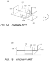
- FIGS. 1A and 1B illustrate a known digital folded camera 100.
- Camera 100 comprises an optical path folding element (OPFE) 102 e.g. a prism or mirror, a lens 104 with a plurality of lens elements (not visible in this representation, but visible e.g. in FIGS. 2A-D ) and an image sensor 106.
- the lens elements may be (as in FIGS. 2A-2D ) axial symmetric along an optical axis 108. In other embodiments, the lens elements may not be axial symmetric. For example, lens elements may be cut (diced, sliced) into a non-circular shape (not shown).
- the barrel may have a longitudinal symmetry along optical axis 108.
- the cross-section of this barrel is circular. This is however not mandatory and other shapes can be used, e.g. for hosting cut lens elements.
- optical path 112 and 114 which represent portions of the optical path.
- OPFE folds the optical path from a first optical path 112 to a second optical path 114, the latter being substantially parallel to optical axis 108
- OPFE 102 is inclined at substantially 45 degrees with respect to optical axis 108. In FIG. 1A , OPFE 102 is also inclined at substantially 45 degrees with respect to optical path 112.
- image sensor 106 lies in a X-Y plane substantially perpendicular to optical axis 108. This is however not limiting, and image sensor 106 can have a different orientation. For example, and as described in international published patent application WO2016/024192 , image sensor 106 may lie in the XZ plane. In this case, an additional OPFE can be used to reflect the optical rays towards image sensor 106.
- UW camera 130 may include an aperture 132 (indicating the object side of the camera) and an optical lens system 134 (or "Wide lens module") with a symmetry (and optical) axis 136 in the Y direction, as well as a UW image sensor 138.
- the UW camera comprises a UW lens system configured to provide a UW image.
- FOVuw field of view
- FOV W field of view
- a plurality of Wide cameras and/or a plurality of Tele cameras can be incorporated and operative in a single digital camera.
- the FOV T of a Tele camera may be for example 20-50 degrees.
- v a lens-image distance defined by the distance of the 2 nd (or "rear") principal plane of the lens and the image
- u an object-lens distance defined by the distance of the object to the 1 st (or "front”) principal plane of the lens.
- the minus sign is generally not mentioned explicitly.
- a Macro image In the context of digital single-lens reflex (DSLR) cameras, a Macro image is defined by having a M of about 1:1 or larger, e.g. 1:1.1. In the context of smartphones, "Macro image”. may refer to images with M of about 10:1 or even 15:1.
- First smartphone models have entered the consumer market that provide Macro-photography capabilities, usually by enabling very close focusing with a UW camera, which has a relatively short EFL (e.g. 2.5mm).
- a UW camera can focus to the close range required for Macro photography (e.g., 1.5cm to 15cm), but its spatial resolution is poor since its focal length is small and its FOV is large.
- DoF depth of field
- US20150253647A1 discloses a folded lens system that may include multiple lenses with refractive power and a light path folding element. Light entering the camera through lens(es) on a first optical path or axis is refracted to the folding element, which changes direction of the light onto a second optical path or axis with lens(es) that refract the light to form an image plane at a photosensor. At least one of the object side and image side surfaces of at least one of the lens elements may be aspheric. Total track length (TTL) of the lens system may be 16.0 mm or less. The lens system may be configured so that the telephoto ration
- US20200192069A1 discloses a wide-angle lens for imaging objects disposed away from the optical axis towards the periphery of the field of view.
- US5327291A discloses a lens system for a folding reflex camera.
- the system includes: (a) a first group on the object side of the system's stop which (i) has a positive dioptric power, (ii) includes an aspheric surface, and (iii) has a concave surface adjacent to the stop; and (b) a second group on the image side of the stop consisting of either a single positive component or the combination of a single positive component and one or more focusing elements.
- the system includes at least two elements made of materials differing in dispersive powers where at least one of the elements is of plastic.
- the system can comprise just two plastic elements and even with such a simple configuration achieves excellent optical performance including a relatively flat field, relatively low distortion, and at least partial correction for lateral chromatic aberration.
- a Macro camera in mobile devices that captures Macro images from a larger lens-object distance (e.g. 5-15cm) with larger object to image magnification (e.g. 1:1 - 15:1), and which has a high degree of optical Bokeh.
- a larger lens-object distance e.g. 5-15cm
- object to image magnification e.g. 1:1 - 15:1
- folded digital cameras as defined by claim 1. Further details are defined by the dependent claims.
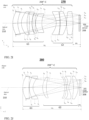
- FIGS. 2A-2J illustrate various lens systems disclosed herein. All lens systems shown in FIG. 2A-J can be included in a folded camera such as shown in FIGS. 1A and 1B .
- FIG. 2A shows schematically an optical lens system disclosed herein and numbered 200.
- Lens system 200 comprises a lens 204, an optical element 206 and an image sensor 208.
- System 200 is shown with ray tracing.
- Optical element 206 may be for example an infra-red (IR) filter, and/or a glass image sensor dust cover.
- IR infra-red
- Optical rays (after their reflection by prism 202) pass through lens 204 and form an image on image sensor 208.
- FIG. 2A shows 3 fields with 3 rays for each: the upper marginal-ray, the lower marginal-ray and the chief-ray.
- the optical rays pass through optical element 206 before impinging on image sensor 208. This is however not limiting, and in some examples, optical element 206 is not present. That is, the optical element may be optional in some designs.
- Lens 204 includes a plurality of N lens elements L i where "i" is an integer between 1 and N.
- N is equal to six. This is however not limiting and a different number of lens elements can be used. According to the claimed invention, N is equal to or greater than 6. For example, N can be equal to 6, 7, 8, 9 or 10.
- L 1 is the lens element closest to the object (prism) side and L N is the lens element closest to the image side, i.e. the side where the image sensor is located. This order holds for all lenses and lens elements disclosed herein.
- Lens elements L i can be used e.g. as lens elements of a camera similar to camera 100.
- the N lens elements are axial symmetric along an optical (lens) axis 210.
- Each lens element L i comprises a respective front surface S 2i-1 (the index “2i-1” being the number of the front surface) and a respective rear surface S 2i (the index “2i” being the number of the rear surface).
- This numbering convention is used throughout the description.
- lens surfaces are marked as “S k ", with k running from 1 to 2N.
- the front surface and the rear surface can be in some cases aspherical. This is however not limiting.
- each lens element refers to the surface of a lens element located closer to the entrance of the camera (camera object side), and the term “rear surface” refers to the surface of a lens element located closer to the image sensor (camera image side).
- a clear height value CH(S k ) and a clear aperture value CA(S k ) can be defined for each surface S k (for 1 ⁇ k ⁇ 2N.
- CA(S k ) and CH(S k ) define optical properties of each surface S k of each lens element.
- the CH term is defined with reference to FIG. 4 and the CA term is defined with reference to FIG. 5 .
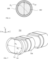
- H Li (for 1 ⁇ i ⁇ N) is defined for each lens element L i .
- H Li corresponds, for each lens element L i , to the maximal height of lens element L i measured along an axis perpendicular to the optical axis of the lens elements.
- the respective H Li is greater than, or equal to the CH and the CA of the front and rear surfaces of this given lens element.
- H Li is the diameter of lens element L i as seen in FIG. 6 .
- H Li max ⁇ CA(S 2i-1 ), CA(S 2i ) ⁇ + a mechanical part size.
- the mechanical part size is defined as not contributing to the optical properties of the lens. Consequently, one defines two heights of a lens element L i , an optical height H opt,i (corresponding to the CA value) of an optically active area 602 and a geometrical height of the lens H Li of an entire lens area 604 which covers an optically active and an optically inactive area.
- the mechanical part and its properties are defined below.
- the mechanical part size contribution to H Li is typically 200-1000 ⁇ m.
- lens system 200 some of the surfaces of the lens elements are represented as convex, and some are represented as concave.
- the representation of FIG. 2A is however not limiting, and a different combination of convex and/or concave surfaces can be used, depending on various factors such as the application, the desired optical power, etc.
- each optical ray that passes through a surface S k impinges this surface on an impact point IP.
- Optical rays enter optical lens system 200 from surface S 1 and pass through surfaces S 2 to S 2N .
- Some optical rays can impinge on any surface S k but cannot /will not reach image sensor 208.
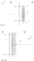
- CH(S k ) is defined as the distance between two closest possible parallel lines, see lines 400 and 402 in FIG. 4 located on a plane P orthogonal to the optical axis of the lens elements.
- plane P is parallel to plane X-Y and is orthogonal to optical axis 302 such that the orthogonal projection IP orth of all impact points IP on plane P is located between the two parallel lines.
- CH(S k ) does not depend on the object currently imaged, since it refers to the optical rays that "can” form an image on the image sensor. Thus, even if the currently imaged object is located in a black background that does not produce light, the definition does not refer to this black background since it refers to any optical rays that "can” reach the image sensor to form an image (for example optical rays emitted by a background which would emit light, contrary to a black background).
- FIG. 3A illustrates the orthogonal projections IP orth,1 , IP orth,2 of two impact points IP 1 and IP 2 on plane P which is orthogonal to optical axis 302.
- surface S k is convex.
- FIG. 3B illustrates the orthogonal projections IP orth,3 , IP orth,4 of two impact points IP 3 and IP 4 on plane P.
- surface S k is concave.
- the orthogonal projection IP orth of all impact points IP of a surface S k on plane P is located between parallel lines 400 and 402.
- CH(S k ) is thus the distance between lines 400 and 402.
- a clear aperture CA(S k ) is defined for each given surface S k (for 1 ⁇ k ⁇ 2N), as the diameter of a circle, wherein the circle is the smallest possible circle located in a plane P orthogonal to the optical axis 108 and encircling all orthogonal projections IP orth of all impact points on plane P.
- the definition of CA(S k ) also does not depend on the object which is currently imaged.
- the circumscribed orthogonal projection IP orth of all impact points IP on plane P is a circle 500.
- the diameter of circle 500 defines CA(S k ).
- the Z axis is positive towards image. Values for CA are given as a clear aperture radius, i.e. CA/2.
- the reference wavelength is 555.0 nm. Units are in mm except for refraction index ("Index") and Abbe #.
- Each lens element L i has a respective focal length f i , given in Table 1.
- the FOV is given as half FOV (HFOV).
- the definitions for surface types, Z axis, CA values, reference wavelength, units, focal length and HFOV are valid for Tables 1-17.
- Table 3 provides details on the variation of the properties of lens system 200 with the object-lens distance.
- the object-lens distance is defined by the distance of the object to the 1 st principal plane of the lens.
- Table 4 provides details on the maximum (image-side) CRAs of lens system 200.
- the maximum CRA and Half FOV (HFOV) are given for several object-lens distances ("Object").
- Data refers to a field of 3.5mm, corresponding to an edge of the image sensor (i.e. upper end of sensor diagonal).
- the focal length f N of the last lens element L N is smaller than the lens' TTL.
- the TTL of lens 204 is 18mm.
- the focusing range of lens system 200 is from infinity to 100mm.
- the focusing range of a lens system is defined as all object-lens distances that can be focused to by means of a camera mechanism that controls the distance between lens and image sensor. That is, for each object located within the focus range, a focusing mechanism can set a particular lens-image sensor distance that results in maximum contrast for the object's image. Maximum contrast means that for lens-image sensor distances other than the particular lens-image sensor distance, the object's contrast will decrease.
- the minimal object distance (MIOD) is defined as the lower limit of the focusing range, i.e. the MIOD is the smallest object-lens distance that the lens system can focus to. For lens system 200, the MIOD is 100mm. Lens system 200 can focus continuously from infinity to 100mm, i.e. any focus position between Infinity to 100mm (as well as any magnification between 0 and -0.153) can be realized.
- lens stroke For changing focus from infinity to 100mm, a lens movement ("lens stroke") of 2.272 mm is required.
- an actuator as known in the art may be used, e.g. a voice coil motor (VCM).
- VCM voice coil motor
- a Hall sensor-magnet geometry for large stroke linear position sensing which is required for VCMs supporting large strokes such as 2mm or more is described in the US Provisional Patent Application No. 63,059,200 .
- lens system 200 At the MIOD, lens system 200 achieves a magnification of -0.153, corresponding to an object-image ratio of ca. 6.5:1.
- the HFOV decreases from 13.25 degrees when focused to infinity to 12.34 degrees when focused to the MIOD.
- lens system 200 has a maximum field curvature (MFC) smaller than 50 ⁇ m.
- MFC may be defined as follows: when placing a lens such as lens 204 at a distance v from a flat image sensor such as image sensor 208, image points at the optical axis will be in perfect focus, but image points off the optical axis will come into focus not at the image sensor, but at a distance v' smaller than v, wherein v' is less than MFC for all image points.
- a lens such as lens 204 can be divided into two lens groups, a first lens group ("focusing group” or “G1”) and a second lens group ("CRA correction group” or “G2").
- the focusing group includes lens elements L 1 , L 2 , L 3 and L 4 .
- the CRA correction group includes L 4 and L 5 .
- lens elements are cut to a non-circular shape ("D-cut").
- the cut lens elements may be obtained by cutting the large lens elements of lens 204 to a height of e.g. 6mm (in Y direction), so that the lens is now a cut lens 204-C. That is, the lens elements L i of lens 204 that have height H Li > 6mm (i.e. L 1 , L 5 and L 6 ) are cut to 6mm. Lens elements are cut in the Y-direction. The cut is performed symmetrically, i.e. the cut top part (defined by larger Y values in FIG.
- a folded lens having large CA and low CH is beneficial for having a low f/# folded lens that is compatible with e.g. a smartphone's height constraints.
- the CA of lens elements L 2 , L 3 and L 4 may be oriented in any direction, e.g. in Y direction.
- the CA of lens element L 1 , L 5 and L 6 is oriented in the X direction (not visible here).
- a cut lens may be achieved by cutting the large lens elements of lens 204 to a height of e.g. 6.5mm, 5mm or 4mm (in the Y direction), i.e. lens elements L i that have height H Li > 6.5mm, 5mm or 4.5mm may be cut to 6.5mm, 5mm or 4.5mm respectively.
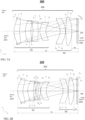
- FIG. 2B depicts schematically another optical lens system disclosed herein and numbered 220.
- Lens system 220 comprises a lens 204' with a plurality of lens elements, optical element 206 (optional) and image sensor 208. Ray tracing is provided as in FIG. 2A .
- Detailed optical data and surface data are given in Tables 5, 6, 7 and 8.
- Table 8 provides details on the maximum CRAs of lens system 220. Notation and field are identical to Table 4.
- FIG. 2B shows 3 fields with 3 rays for each: the upper marginal-ray, the lower marginal-ray and the chief-ray.
- the focusing range of lens system 220 is from infinity to 100mm, i.e. the MIOD is 100mm.
- lens system 210 For focusing with lens 204', all lens elements are moved together. For changing focus from infinity to 100mm, a lens stroke of 2.237 mm is required. For moving the lens, an actuator as known in the art may be used, e.g. a VCM.
- lens system 210 achieves a magnification of -0.15, corresponding to an object-image ratio of ca. 6.7:1.
- the HFOV decreases from 13.29 degrees when focused to infinity to 12.51 degrees when focused to the MIOD. Any focus position between infinity to 100mm (as well as any magnification between 0 and -0.15) can be realized.
- lens system 220 has a maximum field curvature (MFC) ⁇ 50 ⁇ m.
- Lens 204' can be divided into two groups, a first focusing group which includes lens elements L 1 , L 2 , L 3 , L 4 and L 5 and a second CRA correction group which includes L 6 and L 7 .
- the TTL of lens 204' is 18mm.
- FIG. 2H an embodiment numbered 260 of a lens system with a D-cut lens 204'-C based on lens 204'.
- D-cut lens 204'-C is obtained by cutting the large lens elements of lens 204' to a height of e.g. 6mm (in the Y direction), i.e. the lens elements L i of lens 204' that have height H Li > 6mm (i.e. L 1 , L 6 and L 7 ) are cut to 6mm.
- a cut lens may be achieved by cutting the large lens elements of lens 204' to a height of e.g. 6.5mm, 5mm or 4mm (in the Y direction), i.e. the lens elements L i that have height H Li > 6.5mm, 5mm or 4.5mm may be cut to 6.5mm, 5mm or 4.5mm respectively.
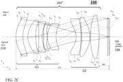
- FIG. 2C depicts schematically another optical lens system disclosed herein and numbered 230.
- Lens system 230 comprises a lens 204", optical element 206 (optional) and image sensor 208. Ray tracing is provided as in FIG. 2A-2B .
- Detailed optical data and surface data are given in Tables 9, 10, 11 and 12.
- Table 12 provides details on the maximum CRAs of lens system 220. Notation and field are identical to Table 4.
- FIG. 2C shows 3 fields with 3 rays for each: the upper marginal-ray, the lower marginal-ray and the chief-ray.
- the focusing range of lens system 230 is from infinity to 76.4mm, i.e. the MIOD is 76.4mm.
- the MIOD is 76.4mm.
- lens 204" For focusing with lens 204" , all lens elements are moved together. For changing focus from Infinity to 100mm, a lens stroke of 2.881 mm is required.
- an actuator e.g. a VCM
- lens system 230 achieves a magnification of -0.195, corresponding to an object-image ratio of ca. 5.1:1.
- the HFOV decreases from 13.29 degrees when focused to infinity to 12.52 degrees when focused to the MIOD. Any focus position between Infinity to 76.4mm (as well as any magnification between 0 and -0.195) can be realized.
- lens system 230 has a MFC ⁇ 50 ⁇ m.
- Lens 204" can be divided into two groups, a first focusing group that includes L 1 , L 2 , L 3 , L 4 and L 5 and a second CRA correction group that includes L 6 , L 7 and L 8 .
- the TTL of lens 204" is 18mm.
- FIG. 2I shows an embodiment numbered 270 of a lens system with a cut lens 204"-C based on lens 204" .
- lens 204"-C is obtained by cutting the large lens elements of lens 204" to a height of e.g. 6mm (in Y direction).
- the lens elements L i of lens 204" that have height H Li > 6mm i.e. L 1 , L 2 , L 6 , L 7 and L 8 ) are cut to 6mm.
- a cut lens may be achieved by cutting the large lens elements of lens 204" to a height of e.g. 6.5mm, 5mm or 4mm (in the Y direction).
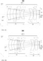
- FIGS. 2D-2F depict schematically yet another optical lens system disclosed herein and numbered 240.
- Lens system 240 comprises a lens 204′′′, optical element 206 (optional) and image sensor 208.
- Ray tracing is provided as in FIG. 2A-2C .
- Detailed optical data and surface data are given in Tables 13, 14, 15, 16 and 17.
- Table 17 provides details on the Max CRAs of lens system 240. Notation and field are identical to Table 4.
- FIGS. 2D-2F show three fields with 3 rays for each: the upper marginal-ray, the lower marginal-ray and the chief-ray.
- FIG. 2D shows lens system 240 focused to infinity ("Config. A")
- FIG. 2E shows lens system 240 focused to 100mm (“Config. B")
- FIG. 2F shows lens system 240 focused to 50mm (“Config. C”).
- the object-lens distance focused on is given by Surface 0 in Table 15.
- the focusing range of lens system 240 is from infinity to 50mm, i.e. the MIOD is 50mm.
- Lens 204′′′ is divided into two groups that move relative to each other for focusing.
- a first lens group (“G1”) includes lens elements L 1 and L 2
- a second lens group (“G2”) includes L 3 , L 4 , L 5 and L 6 .
- the big gap of between G1 and G2 decreases from 2.625mm when focused to Infinity to 1.946mm when focused to 100mm, and to 1.303mm when focused to 50mm (see Surface # 5 in table 15).
- lens 204′′′ also moves as one unit so that the BFL changes (see Surface # 13 in Table 15).
- an actuator e.g. VCM
- lens system 240 achieves a magnification of -0.40, corresponding to an object-image ratio of ca. 2.5:1.
- the HFOV decreases from 13.1 degrees when focused to infinity to 9.3 degrees when focused to the MIOD (see Table 16). Any focus position between Infinity to 50mm (as well as any magnification between 0 and -0.4) can be realized.
- FIG. 2J shows an embodiment numbered 280 of a lens system with a cut lens 204′′′-C based on lens 204′′′.
- Cut lens 204′′′-C is obtained by cutting the large lens elements of lens 204′′′ to a height of 6mm (in Y direction), i.e. the lens elements L i of lens 204′′′ that have height H Li > 6mm (L 1 , L 2 , L 5 and L 6 ) are cut to 6mm.
- a cut lens may be achieved by cutting the large lens elements of lens 204′′′ to a height of e.g. 6.5mm, 5mm or 4mm (in the Y direction).
- Table 18 shows an overview on the EFLs of all lens elements of the G1 and G2 respectively as well as ratios EFL1/EFL2 for lens system embodiments 200, 220, 230, 240 and 290.
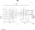
- FIG. 2K depicts schematically another optical lens system disclosed herein and numbered 290.
- Lens system 290 comprises a lens 204 ⁇ with a plurality of lens elements, optical element 206 (optional) and image sensor 208. Ray tracing is provided as in FIG. 2A .
- lens system 290 For focusing with lens 204 ⁇ , all lens elements are moved together. For changing focus from infinity to 52mm, a lens stroke of 4.507mm is required. At the MIOD, lens system 290 achieves a magnification of -0.29, corresponding to an object-image ratio of ca. 3.4:1. The HFOV decreases from 9.57 degrees when focused to infinity to 8.52 degrees when focused to the MIOD. Any focus position between infinity to 52mm (as well as any magnification between 0 and -0.29) can be realized. For any object within the focus range, lens system 290 has a MFC ⁇ 50 ⁇ m.
- Lens 204 ⁇ can be divided into two groups, a first focusing group that includes L 1 , L 2 , L 3 , L 4 and L 5 and a second CRA correction group that includes L 6 , L 7 and L 8 .
- the TTL of lens 204 ⁇ is 18.6mm.
- Some embodiments may include a cut lens based on lens 204 ⁇ .
- the cut lens may be achieved by cutting the large lens elements of lens 204 ⁇ to a height of e.g. 6.5mm, 5mm or 4mm (in the Y direction). For details on cut lenses, it is referred to the description of FIG. 2A .
- At least part of the lens elements can have a shape (profile) in cross-section (in plane X-Y, which is orthogonal to the optical lens system and which generally coincides with the optical axis) that is not circular.
- at least some of the lens elements can have a width W Li (measured along axis X) which is greater than their height H Li (measured along axis Y).
- Barrel 700 further comprises a barrel wall (or surrounding) 704.
- the height H Li can correspond to the total height of the lens element (including the mechanical part).
- a lens element in lens barrel 700 may have a symmetry about axis Y and/or about axis X.
- a non-circular lens barrel such as 700 maybe shaped according to the cut lens elements of a lens such as e.g. lens 204-C.
- the height of a lens barrel may be only slightly higher than the lens element having the largest height in the lens.
- a lens barrel may be 0 - 0.5 mm higher than the highest lens element.
- a lens barrel having an identical height as the highest lens element is described for example in co-owned international patent application PCT/IB2018/050988 , which is incorporated herein by reference in its entirety.
- W Li is substantially greater than H Li (for example, by at least a percentage which is equal or greater than 20%, these values being not limiting). In some examples, W Li may be greater than H Li by a percentage of 20-70%.
- lens element L 8 of folded lens 204' as an example: W L8 is greater than H L8 by a percentage of 32%.
- the term “substantially” is used herein to imply the possibility of variations in values within an acceptable range. According to one example, the term “substantially” used herein should be interpreted to imply possible variation of up to 10% over or under any specified value. According to another example, the term “substantially” used herein should be interpreted to imply possible variation of up to 5% over or under any specified value. According to a further example, the term “substantially” used herein should be interpreted to imply possible variation of up to 2.5% over or under any specified value.
Landscapes
- Physics & Mathematics (AREA)
- General Physics & Mathematics (AREA)
- Engineering & Computer Science (AREA)
- Optics & Photonics (AREA)
- Multimedia (AREA)
- Signal Processing (AREA)
- Chemical & Material Sciences (AREA)
- Combustion & Propulsion (AREA)
- Electromagnetism (AREA)
- Power Engineering (AREA)
- Lenses (AREA)
Claims (12)
- Gefaltete Digitalkamera, die Folgendes umfasst:a) ein Linsensystem (200, 220, 230, 240, 290) mit einer Linse (204, 204', 204", 204‴, 204ʺʺ, 204-C, 204'-C, 204"-C, 204"'-C) und einem Bildsensor (208), wobei die Linse N ≥ 6 Linsenelemente Li, eine effektive Brennweite (EFL) und eine Gesamtbahnlänge (TTL) hat, wobei jedes Linsenelement eine jeweilige Brennweite fi aufweist, und wobei ein erstes Linsenelement L1 einer Objektseite zugewandt ist; undb) ein Lichtwegfaltelement (OPFE) (102) zum Bereitstellen eines gefalteten Lichtwegs zwischen einem Objekt und der Linse,wobei das Linsensystem einen Fokussierbereich aufweist, der Objekt-Linsen-Distanzen von unendlich bis zu einer minimalen Objektdistanz (MIOD) abdeckt, und wobei 3,33 ≤ MIOD/EFL < 7 ist,wobei die Linsenelemente in zwei Linsenelementgruppen unterteilt sind, die durch einen großen Spalt größer als TTL/7 getrennt sind.
- Gefaltete Digitalkamera nach Anspruch 1, wobei eine maximale Feldkrümmung MFC für jedes Objekt innerhalb des Fokusbereichs kleiner als 50 µm ist.
- Gefaltete Digitalkamera nach Anspruch 1, wobei die Kamera eine f-Zahl < 3 hat.
- Gefaltete Digitalkamera nach Anspruch 1, wobei die Linsenelemente in eine erste Linsenelementgruppe mit einer effektiven Brennweite EFL1 und eine zweite Linsenelementgruppe mit einer effektiven Brennweite EFL2 unterteilt sind, und wobei ein Verhältnis EFL1/EFL2 um nicht mehr als 10 % von 1 abweicht.
- Gefaltete Digitalkamera nach Anspruch 1, wobei die Linsenelemente in eine erste Linsenelementgruppe mit einer effektiven Brennweite EFL1 und eine zweite Linsenelementgruppe mit einer effektiven Brennweite EFL2 unterteilt sind, und wobei ein Verhältnis EFL1/EFL2 um nicht mehr als 20 % von 1 abweicht.
- Gefaltete Digitalkamera nach Anspruch 1, die ferner einen auf einem Schwingspulenmotor basierenden Fokussiermechanismus zum Fokussieren der Kamera umfasst.
- Gefaltete Digitalkamera nach Anspruch 1, wobei das erste Linsenelement L1 und ein zweites Linsenelement L2 aus einem Material mit einer Abbe-Zahl von mehr als 50 hergestellt sind.
- Gefaltete Digitalkamera nach Anspruch 1, wobei TTL/EFL < 1,4 ist.
- Gefaltete Digitalkamera nach Anspruch 1, wobei ein Verhältnis zwischen der Brennweite fN des letzten Linsenelements LN und der TTL fN/TTL < 1,0 erfüllt.
- Gefaltete Digitalkamera nach Anspruch 1, wobei ein Verhältnis zwischen der Brennweite fN des letzten Linsenelements LN und der TTL fN/TTL < 0,8 erfüllt.
- Gefaltete Digitalkamera nach Anspruch 1, die zusätzlich ein optisches Element einschließt, wobei sich das optische Element zwischen der Linse und dem Bildsensor befindet.
- Gefaltete Digitalkamera nach Anspruch 1, wobei ein Verhältnis zwischen einem maximalen Hauptstrahlwinkel (Max CRA) und einem Sichtfeld (FOV) der gefalteten Kamera Max CRA/FOV kleiner als 0,25 ist, wenn die Kamera auf unendlich fokussiert ist.
Priority Applications (1)
| Application Number | Priority Date | Filing Date | Title |
|---|---|---|---|
| EP24189269.4A EP4425256A3 (de) | 2020-07-31 | 2021-07-14 | Gefaltete linsendesigns für makrotelekamera |
Applications Claiming Priority (3)
| Application Number | Priority Date | Filing Date | Title |
|---|---|---|---|
| US202063059200P | 2020-07-31 | 2020-07-31 | |
| US202063070501P | 2020-08-26 | 2020-08-26 | |
| PCT/IB2021/056358 WO2022023855A1 (en) | 2020-07-31 | 2021-07-14 | Folded macro-tele camera lens designs |
Related Child Applications (2)
| Application Number | Title | Priority Date | Filing Date |
|---|---|---|---|
| EP24189269.4A Division EP4425256A3 (de) | 2020-07-31 | 2021-07-14 | Gefaltete linsendesigns für makrotelekamera |
| EP24189269.4A Division-Into EP4425256A3 (de) | 2020-07-31 | 2021-07-14 | Gefaltete linsendesigns für makrotelekamera |
Publications (4)
| Publication Number | Publication Date |
|---|---|
| EP4038433A1 EP4038433A1 (de) | 2022-08-10 |
| EP4038433A4 EP4038433A4 (de) | 2022-12-21 |
| EP4038433C0 EP4038433C0 (de) | 2025-03-19 |
| EP4038433B1 true EP4038433B1 (de) | 2025-03-19 |
Family
ID=80037724
Family Applications (2)
| Application Number | Title | Priority Date | Filing Date |
|---|---|---|---|
| EP24189269.4A Pending EP4425256A3 (de) | 2020-07-31 | 2021-07-14 | Gefaltete linsendesigns für makrotelekamera |
| EP21850021.3A Active EP4038433B1 (de) | 2020-07-31 | 2021-07-14 | Gefaltete makro-tele-kameraobjektive |
Family Applications Before (1)
| Application Number | Title | Priority Date | Filing Date |
|---|---|---|---|
| EP24189269.4A Pending EP4425256A3 (de) | 2020-07-31 | 2021-07-14 | Gefaltete linsendesigns für makrotelekamera |
Country Status (6)
| Country | Link |
|---|---|
| US (3) | US11914117B2 (de) |
| EP (2) | EP4425256A3 (de) |
| KR (3) | KR20250038813A (de) |
| CN (6) | CN114270240B (de) |
| TW (2) | TWI862858B (de) |
| WO (1) | WO2022023855A1 (de) |
Families Citing this family (3)
| Publication number | Priority date | Publication date | Assignee | Title |
|---|---|---|---|---|
| TWI793799B (zh) * | 2021-06-16 | 2023-02-21 | 大立光電股份有限公司 | 成像鏡頭模組與電子裝置 |
| KR20230162394A (ko) * | 2022-05-20 | 2023-11-28 | 엘지이노텍 주식회사 | 광학계 및 이를 포함하는 카메라 모듈 |
| CN120161661A (zh) * | 2023-02-15 | 2025-06-17 | 核心光电有限公司 | 用于折叠相机的大角度紧凑型光学图像稳定化 |
Family Cites Families (296)
| Publication number | Priority date | Publication date | Assignee | Title |
|---|---|---|---|---|
| US2106752A (en) | 1934-12-03 | 1938-02-01 | Sheet Polarizer Company Inc | Field divider |
| US2354503A (en) | 1941-12-01 | 1944-07-25 | Taylor Taylor & Hobson Ltd | Optical objective of the telephoto type |
| US2378170A (en) | 1943-06-25 | 1945-06-12 | Eastman Kodak Co | Telephoto lens |
| US2441093A (en) | 1946-07-22 | 1948-05-04 | Eastman Kodak Co | Telephoto lens |
| US3388956A (en) | 1963-04-10 | 1968-06-18 | Voigtlaender Ag | Photographic telephoto lenses of high telephoto power |
| DE1447278A1 (de) | 1964-06-20 | 1968-12-19 | Voigtlaender Ag | Tele-Anastigmat mittlerer Lichtstaerke mit grossem Telephoto-Effekt |
| US3558218A (en) | 1967-12-01 | 1971-01-26 | Polaroid Corp | Three-element telephoto objective lens |
| JPS5116135B2 (de) | 1972-05-10 | 1976-05-21 | ||
| US3942876A (en) | 1972-09-07 | 1976-03-09 | Ponder & Best, Inc. | Telephoto lens |
| JPS5327421A (en) | 1976-08-26 | 1978-03-14 | Asahi Optical Co Ltd | Small telephotographic lens |
| JPS54157620A (en) | 1978-06-01 | 1979-12-12 | Konishiroku Photo Ind Co Ltd | Photographic telephoto lens |
| JPS55163510A (en) | 1979-06-06 | 1980-12-19 | Nippon Kogaku Kk <Nikon> | Telephoto lens |
| JPS5850509A (ja) | 1981-09-21 | 1983-03-25 | Ricoh Co Ltd | 小型望遠レンズ |
| JPS59121015A (ja) | 1982-12-28 | 1984-07-12 | Nippon Kogaku Kk <Nikon> | 近距離補正された写真レンズ |
| JPS6370211A (ja) | 1986-09-11 | 1988-03-30 | Canon Inc | プラスチツク製光学素子 |
| JPH0690350B2 (ja) | 1986-12-15 | 1994-11-14 | 富士写真光機株式会社 | カメラ |
| JPH0233117A (ja) | 1988-07-22 | 1990-02-02 | Ricoh Co Ltd | レンズ光軸調整装置 |
| US5000551A (en) | 1989-06-05 | 1991-03-19 | Nikon Corporation | Zoom lens |
| JP3103166B2 (ja) | 1991-11-26 | 2000-10-23 | 富士写真光機株式会社 | 射出瞳の遠いマクロレンズ |
| US5327291A (en) | 1992-03-30 | 1994-07-05 | Polaroid Corporation | Compact objective lens |
| JPH0659195A (ja) | 1992-08-07 | 1994-03-04 | Fuji Photo Optical Co Ltd | 内視鏡用光学系装置 |
| JPH06165212A (ja) | 1992-11-26 | 1994-06-10 | Sanyo Electric Co Ltd | ビデオ信号処理用集積回路 |
| JP3358639B2 (ja) | 1994-05-31 | 2002-12-24 | 京セラ株式会社 | カメラのフォーカス制御方式 |
| JPH07333505A (ja) | 1994-06-10 | 1995-12-22 | Canon Inc | 撮像装置 |
| JP3210242B2 (ja) | 1995-03-06 | 2001-09-17 | 川崎製鉄株式会社 | 黒鉛含有不定形耐火物 |
| JP3851677B2 (ja) | 1996-02-06 | 2006-11-29 | オリンパス株式会社 | ズームレンズ |
| JP3676524B2 (ja) | 1996-10-25 | 2005-07-27 | ペンタックス株式会社 | プリズム |
| JPH1195105A (ja) | 1997-07-22 | 1999-04-09 | Nikon Corp | 変倍光学系の合焦方式 |
| JP3811281B2 (ja) | 1997-12-10 | 2006-08-16 | オリンパス株式会社 | ズームレンズ鏡筒 |
| JPH11223771A (ja) | 1998-02-06 | 1999-08-17 | Nikon Corp | 可変焦点距離レンズ系 |
| US6147702A (en) | 1998-04-17 | 2000-11-14 | Intel Corporation | Calibration of digital cameras |
| JP3570253B2 (ja) | 1998-10-28 | 2004-09-29 | ソニー株式会社 | ズームレンズ |
| JP2000292848A (ja) | 1999-04-06 | 2000-10-20 | Fuji Photo Film Co Ltd | 光学機器 |
| US6195209B1 (en) | 1999-05-04 | 2001-02-27 | U.S. Precision Lens Incorporated | Projection lenses having reduced lateral color for use with pixelized panels |
| JP4278879B2 (ja) | 2001-02-27 | 2009-06-17 | 株式会社オートネットワーク技術研究所 | 車両周辺視認装置 |
| JP2003057546A (ja) | 2001-08-20 | 2003-02-26 | Pentax Corp | ズームレンズ系 |
| JP3503941B2 (ja) | 2002-02-04 | 2004-03-08 | 富士写真光機株式会社 | 3群ズームレンズ |
| CN100449268C (zh) | 2003-02-14 | 2009-01-07 | Bei传感器及系统有限公司 | 使用线性霍尔效应传感器、具有增强线性磁体配置的位置传感器 |
| JP2004334185A (ja) | 2003-04-18 | 2004-11-25 | Canon Inc | ズームレンズ |
| US6924948B2 (en) | 2003-08-21 | 2005-08-02 | Arc Design, Inc. | Multifocal lens system for digital cameras |
| JP4276914B2 (ja) | 2003-09-18 | 2009-06-10 | オリンパス株式会社 | 振動波リニアモータ及びその駆動方法 |
| JP2005134486A (ja) | 2003-10-28 | 2005-05-26 | Ricoh Co Ltd | カラー画像読取レンズ、カラー画像読取レンズユニット、カラー画像読取装置および画像形成装置 |
| JP2005173191A (ja) | 2003-12-11 | 2005-06-30 | Olympus Corp | 光路折り曲げ光学系 |
| JP2005215473A (ja) | 2004-01-30 | 2005-08-11 | Sekinosu Kk | 投影レンズ装置 |
| US6980379B1 (en) | 2004-07-19 | 2005-12-27 | Microalign Technologies, Inc. | Flat wide-angle objective |
| JP4684597B2 (ja) | 2004-08-13 | 2011-05-18 | Hoya株式会社 | レンズ制御装置 |
| JP2006154702A (ja) | 2004-10-29 | 2006-06-15 | Konica Minolta Opto Inc | 変倍光学系、撮像レンズ装置及びデジタル機器 |
| US9155483B2 (en) | 2004-12-03 | 2015-10-13 | The Invention Science Fund I, Llc | Vision modification with reflected image |
| JP4679906B2 (ja) | 2005-01-13 | 2011-05-11 | 株式会社リコー | レンズ固定構造 |
| US7206136B2 (en) | 2005-02-18 | 2007-04-17 | Eastman Kodak Company | Digital camera using multiple lenses and image sensors to provide an extended zoom range |
| JP4641203B2 (ja) | 2005-03-07 | 2011-03-02 | 株式会社リコー | レンズ鏡胴、このレンズ鏡胴を用いたカメラ及び携帯型情報端末装置 |
| JP4731977B2 (ja) | 2005-04-22 | 2011-07-27 | キヤノン株式会社 | 光学機器 |
| JP4794912B2 (ja) | 2005-06-02 | 2011-10-19 | キヤノン株式会社 | ズームレンズ及びそれを有する撮像装置 |
| JP2007133096A (ja) | 2005-11-09 | 2007-05-31 | Konica Minolta Opto Inc | 撮像光学系、撮像レンズ装置及びデジタル機器 |
| JP2007164065A (ja) | 2005-12-16 | 2007-06-28 | Konica Minolta Opto Inc | レンズユニット及び撮像装置 |
| JP2007219199A (ja) | 2006-02-17 | 2007-08-30 | Konica Minolta Opto Inc | レンズユニット、撮像装置及びレンズの製造方法 |
| JP4916198B2 (ja) | 2006-03-20 | 2012-04-11 | 株式会社リコー | ズームレンズ、ズームレンズを有する撮像装置、カメラ装置および携帯情報端末装置 |
| JP4905653B2 (ja) | 2006-03-28 | 2012-03-28 | ペンタックスリコーイメージング株式会社 | 中望遠レンズ系 |
| JP2007310343A (ja) | 2006-04-17 | 2007-11-29 | Sharp Corp | レンズ鏡筒およびレンズ鏡筒の組立方法およびカメラモジュール |
| JP2007306282A (ja) | 2006-05-11 | 2007-11-22 | Citizen Electronics Co Ltd | カメラモジュール |
| KR100799216B1 (ko) * | 2006-07-25 | 2008-01-29 | 삼성테크윈 주식회사 | 대구경 표준 렌즈 |
| KR100900486B1 (ko) | 2006-09-04 | 2009-06-03 | 삼성테크윈 주식회사 | 촬상 장치용 광학 모듈 및 이를 구비한 촬상 장치 |
| JP4956343B2 (ja) | 2006-09-25 | 2012-06-20 | 富士フイルム株式会社 | 2焦点撮像光学系および撮像機器 |
| US7515345B2 (en) | 2006-10-09 | 2009-04-07 | Drs Sensors & Targeting Systems, Inc. | Compact objective lens assembly |
| KR20080032759A (ko) | 2006-10-10 | 2008-04-16 | 삼성전기주식회사 | 카메라 모듈의 렌즈배럴 및 이를 조립하는 레이져장치 |
| KR101278239B1 (ko) | 2006-10-17 | 2013-06-24 | 삼성전자주식회사 | 듀얼 렌즈 광학계 및 이를 구비하는 듀얼 렌즈 카메라 |
| JP2008102427A (ja) | 2006-10-20 | 2008-05-01 | Tamron Co Ltd | 光学装置および撮像装置 |
| JP2008111876A (ja) | 2006-10-27 | 2008-05-15 | Sony Corp | カメラモジュール |
| JP4994812B2 (ja) | 2006-12-05 | 2012-08-08 | キヤノン株式会社 | 撮像装置 |
| JP2008191423A (ja) | 2007-02-05 | 2008-08-21 | Sharp Corp | レンズユニット及びカメラモジュール、並びに該カメラモジュールを備えた撮像装置 |
| JP5000403B2 (ja) | 2007-03-28 | 2012-08-15 | 富士フイルム株式会社 | 変倍光学系および撮像装置 |
| TWI332584B (en) | 2007-04-25 | 2010-11-01 | Largan Precision Co Ltd | Optical lens system for taking image |
| US8794526B2 (en) | 2007-06-04 | 2014-08-05 | Hand Held Products, Inc. | Indicia reading terminal processing plurality of frames of image data responsively to trigger signal activation |
| JP2008304708A (ja) | 2007-06-07 | 2008-12-18 | Konica Minolta Opto Inc | ズームレンズ及び撮像装置 |
| TWI351530B (en) | 2007-07-05 | 2011-11-01 | Largan Precision Co Ltd | Inverse telephoto with correction lenses |
| TWI354820B (en) | 2007-08-14 | 2011-12-21 | Largan Precision Co Ltd | Optical lens system for taking image |
| KR100921146B1 (ko) | 2007-08-21 | 2009-10-12 | 엘지이노텍 주식회사 | 렌즈 모듈 |
| JP4947423B2 (ja) | 2007-08-29 | 2012-06-06 | コニカミノルタオプト株式会社 | 撮像レンズ |
| EP2037306A1 (de) | 2007-09-12 | 2009-03-18 | Fujinon Corporation | Abbildungslinse und Abbildungsvorrichtung |
| US7710665B2 (en) | 2007-11-08 | 2010-05-04 | Samsung Electro-Mechanics Co., Ltd. | Imaging optical system |
| TWI361914B (en) | 2007-11-16 | 2012-04-11 | Largan Precision Co Ltd | Optical lens system for taking image |
| US9118850B2 (en) | 2007-11-27 | 2015-08-25 | Capso Vision, Inc. | Camera system with multiple pixel arrays on a chip |
| JP2009134175A (ja) | 2007-11-30 | 2009-06-18 | Olympus Imaging Corp | 結像光学系 |
| JP2011509415A (ja) | 2007-12-04 | 2011-03-24 | ブラックアイ オプティクス,エルエルシー | 固定群内に液体レンズを有する望遠タイプのズームレンズ |
| KR100956250B1 (ko) | 2007-12-10 | 2010-05-06 | 삼성전기주식회사 | 웨이퍼 스케일 렌즈조립체 제조방법 및 이에 의해 제조된웨이퍼 스케일 렌즈조립체 |
| TWI354821B (en) | 2007-12-18 | 2011-12-21 | Largan Precision Co Ltd | Optical lens system for taking image |
| EP2223173B1 (de) | 2007-12-19 | 2013-09-04 | Heptagon Micro Optics Pte. Ltd. | Kameravorrichtung und herstellungsverfahren dafür |
| WO2009084192A1 (ja) | 2007-12-28 | 2009-07-09 | Panasonic Corporation | レンズ鏡筒およびレンズ支持構造 |
| TWI361915B (en) | 2008-02-18 | 2012-04-11 | Largan Precision Co Ltd | Optical lens system for taking image |
| TWI361903B (en) | 2008-02-27 | 2012-04-11 | Largan Precision Co Ltd | Optical lens system for taking image |
| TWI361913B (en) | 2008-02-27 | 2012-04-11 | Largan Precision Co Ltd | Optical lens system for taking image |
| JP2009216941A (ja) | 2008-03-10 | 2009-09-24 | Tamron Co Ltd | 屈曲変倍光学系 |
| JP2009258286A (ja) | 2008-04-15 | 2009-11-05 | Konica Minolta Opto Inc | 撮像レンズ、撮像ユニット及び携帯端末 |
| CN101576642B (zh) | 2008-05-06 | 2013-04-24 | 鸿富锦精密工业(深圳)有限公司 | 间隔环以及具有该间隔环的镜头模组 |
| KR100962970B1 (ko) | 2008-06-19 | 2010-06-10 | 엘지이노텍 주식회사 | 촬상 렌즈 |
| CN101634738A (zh) | 2008-07-25 | 2010-01-27 | 鸿富锦精密工业(深圳)有限公司 | 镜头模组及相机模组 |
| TWI395992B (zh) | 2008-07-25 | 2013-05-11 | Largan Precision Co | 四片式攝影光學鏡組 |
| JP5137729B2 (ja) | 2008-07-31 | 2013-02-06 | 株式会社オプトロジック | ズームレンズ |
| JP5483842B2 (ja) | 2008-08-06 | 2014-05-07 | キヤノン株式会社 | 撮像装置 |
| JP5304117B2 (ja) | 2008-09-05 | 2013-10-02 | コニカミノルタ株式会社 | 撮像レンズ及び撮像装置並びに携帯端末 |
| US8049979B2 (en) | 2008-09-08 | 2011-11-01 | Panasonic Corporation | Lens barrel and imaging device |
| TWI384254B (zh) | 2008-10-16 | 2013-02-01 | Largan Precision Co Ltd | 取像透鏡組 |
| TWI379102B (en) | 2008-11-20 | 2012-12-11 | Largan Precision Co Ltd | Optical lens system for taking image |
| TWI388878B (zh) | 2008-12-01 | 2013-03-11 | Largan Precision Co Ltd | 取像光學鏡片組 |
| TWI382199B (zh) | 2008-12-16 | 2013-01-11 | Largan Precision Co Ltd | 攝像用透鏡組 |
| JP5201679B2 (ja) | 2008-12-25 | 2013-06-05 | 株式会社オプトロジック | 撮像レンズ |
| JP5300467B2 (ja) | 2008-12-26 | 2013-09-25 | キヤノン株式会社 | 光学系及びそれを有する光学機器 |
| US7826149B2 (en) | 2008-12-27 | 2010-11-02 | Largan Precision Co., Ltd. | Optical lens system for taking image |
| JP2010164841A (ja) | 2009-01-16 | 2010-07-29 | Sharp Corp | 撮像モジュール、撮像装置及び光学機器 |
| TWI394979B (zh) | 2009-01-22 | 2013-05-01 | Largan Precision Co Ltd | 薄型攝影光學鏡組 |
| TWI406004B (zh) | 2009-02-19 | 2013-08-21 | Largan Precision Co Ltd | 成像光學透鏡組 |
| TWI406005B (zh) | 2009-02-24 | 2013-08-21 | Asia Optical Co Inc | 小型化變焦鏡頭及影像擷取裝置 |
| TWI395990B (zh) | 2009-05-11 | 2013-05-11 | Largan Precision Co Ltd | 攝影用透鏡組 |
| TWI401466B (zh) | 2009-06-19 | 2013-07-11 | Largan Precision Co | 二片式攝影光學鏡組 |
| TWI404972B (zh) | 2009-06-19 | 2013-08-11 | Largan Precision Co | 成像光學鏡組 |
| KR20110002630A (ko) | 2009-07-02 | 2011-01-10 | 삼성전자주식회사 | 휴대 단말기의 카메라 운용 방법 및 장치 |
| TWI421557B (zh) | 2009-07-14 | 2014-01-01 | 大立光電股份有限公司 | 攝像透鏡系統 |
| DE102009028861B4 (de) | 2009-08-25 | 2015-03-05 | Trimble Jena Gmbh | Messvorrichtung mit verringertem Anteil an Störlicht und Herstellungsverfahren für diese |
| JP5671684B2 (ja) | 2009-08-31 | 2015-02-18 | パナソニックIpマネジメント株式会社 | レンズ鏡筒、撮像装置および携帯端末装置 |
| JP5405360B2 (ja) | 2009-10-06 | 2014-02-05 | 富士フイルム株式会社 | 撮像レンズおよび撮像装置 |
| US8248523B2 (en) | 2009-11-05 | 2012-08-21 | Flextronics Ap, Llc | Camera module with fold over flexible circuit and cavity substrate |
| US8559118B2 (en) | 2009-11-18 | 2013-10-15 | DigitalOptics Corporation Europe Limited | Fixed focal length optical lens architecture providing a customized depth of focus optical system |
| KR20110058094A (ko) | 2009-11-25 | 2011-06-01 | 삼성전기주식회사 | 렌즈조립체 및 이를 이용한 카메라 모듈 |
| JP2011128445A (ja) | 2009-12-18 | 2011-06-30 | Sony Corp | ズームレンズ及び撮像装置 |
| JP2011138047A (ja) | 2009-12-28 | 2011-07-14 | Olympus Imaging Corp | 光路反射型のズームレンズを備えた撮像装置 |
| JP2011141396A (ja) | 2010-01-06 | 2011-07-21 | Tamron Co Ltd | 撮影レンズ、カメラモジュール、および撮像装置 |
| JP5363354B2 (ja) | 2010-01-12 | 2013-12-11 | 富士フイルム株式会社 | 撮像レンズ、撮像光学系、撮像装置 |
| JP5479123B2 (ja) | 2010-01-19 | 2014-04-23 | 京セラ株式会社 | 撮像装置および電子機器 |
| US8830335B2 (en) | 2010-02-26 | 2014-09-09 | Cambridge Mechatronics Limited | SMA actuation apparatus |
| CN102193162A (zh) | 2010-03-16 | 2011-09-21 | 大立光电股份有限公司 | 可变焦摄影模块 |
| CN103003734B (zh) * | 2010-03-26 | 2016-01-20 | 柯尼卡美能达株式会社 | 摄像透镜、摄像光学装置及数码设备 |
| TWI406027B (zh) | 2010-04-08 | 2013-08-21 | Largan Precision Co Ltd | 取像用光學鏡頭 |
| KR101161951B1 (ko) | 2010-04-15 | 2012-07-04 | 삼성전기주식회사 | 플라스틱 렌즈, 렌즈 모듈, 및 렌즈 사출 금형 |
| JP5498259B2 (ja) | 2010-05-24 | 2014-05-21 | 株式会社タムロン | 高変倍率ズームレンズ |
| TWI401485B (zh) | 2010-06-10 | 2013-07-11 | Largan Precision Co Ltd | 成像光學鏡片組 |
| US8780463B2 (en) | 2010-06-24 | 2014-07-15 | Ricoh Company, Ltd. | Image-forming lens, and imaging apparatus and information device using the image-forming lens |
| TWI431352B (zh) | 2010-09-15 | 2014-03-21 | Largan Precision Co Ltd | 光學成像鏡頭 |
| TWI434096B (zh) | 2010-09-16 | 2014-04-11 | Largan Precision Co Ltd | 光學攝像透鏡組 |
| JP2012068510A (ja) | 2010-09-24 | 2012-04-05 | Hoya Corp | 撮影光学系、及び撮影装置 |
| US20120075518A1 (en) | 2010-09-29 | 2012-03-29 | Hoya Corporation | Imaging unit |
| TWI435135B (zh) | 2010-10-06 | 2014-04-21 | Largan Precision Co Ltd | 光學透鏡系統 |
| US8339714B2 (en) | 2010-10-13 | 2012-12-25 | Olympus Imaging Corp. | Zoom lens and imaging apparatus incorporating the same |
| JP5804878B2 (ja) | 2010-11-01 | 2015-11-04 | キヤノン株式会社 | ズームレンズ及びそれを有する撮像装置 |
| CN102466865B (zh) | 2010-11-15 | 2014-06-04 | 大立光电股份有限公司 | 光学成像镜头组 |
| CN102466867B (zh) | 2010-11-19 | 2014-11-05 | 大立光电股份有限公司 | 光学摄像透镜组 |
| US9146383B2 (en) | 2010-11-23 | 2015-09-29 | Umicore | Super wide angle lens arrangement for infrared applications |
| TWI418877B (zh) | 2010-12-15 | 2013-12-11 | Largan Precision Co | 成像用光學系統 |
| KR20120068177A (ko) | 2010-12-17 | 2012-06-27 | 삼성전기주식회사 | 렌즈 조립체 |
| KR101262470B1 (ko) | 2011-01-31 | 2013-05-08 | 엘지이노텍 주식회사 | 렌즈 어셈블리 및 카메라 모듈 |
| JP5802401B2 (ja) | 2011-02-22 | 2015-10-28 | オリンパス株式会社 | レンズ鏡枠およびレンズ組立体 |
| US8976466B2 (en) | 2011-03-11 | 2015-03-10 | Olympus Corporation | Imaging optical system and imaging apparatus using the same |
| JP2012203234A (ja) | 2011-03-25 | 2012-10-22 | Konica Minolta Advanced Layers Inc | 撮像光学系、撮像装置およびデジタル機器 |
| TWI429979B (zh) | 2011-04-13 | 2014-03-11 | Largan Precision Co Ltd | 光學影像透鏡組 |
| CN102147519B (zh) | 2011-04-20 | 2013-01-09 | 中国科学院光电技术研究所 | 一种宽角和长后工作距离的航测相机全色物镜 |
| JP2012230323A (ja) | 2011-04-27 | 2012-11-22 | Olympus Imaging Corp | レンズ鏡筒および撮像装置 |
| JP5766523B2 (ja) | 2011-06-15 | 2015-08-19 | 株式会社ディスコ | 像側テレセントリック対物レンズおよびレーザー加工装置 |
| JP2013003754A (ja) | 2011-06-15 | 2013-01-07 | Tokai Rika Co Ltd | 入力装置 |
| JP5827688B2 (ja) | 2011-07-25 | 2015-12-02 | 富士フイルム株式会社 | 撮像レンズおよび撮像レンズを備えた撮像装置 |
| KR20130025137A (ko) | 2011-09-01 | 2013-03-11 | 삼성전자주식회사 | 파노라마 촬상 렌즈 및 이를 이용한 파노라마 촬상 시스템 |
| KR101301314B1 (ko) | 2011-10-10 | 2013-08-29 | 삼성전기주식회사 | 촬상렌즈 유닛 |
| JP5904208B2 (ja) | 2011-10-20 | 2016-04-13 | コニカミノルタ株式会社 | 撮像レンズ,撮像光学装置及びデジタル機器 |
| TWI578016B (zh) | 2011-10-24 | 2017-04-11 | 數位光學Mems有限公司 | 具有微機電系統影像聚焦致動器之光學系統 |
| JP5809936B2 (ja) | 2011-11-08 | 2015-11-11 | オリンパス株式会社 | 撮像装置 |
| JP2013105049A (ja) | 2011-11-15 | 2013-05-30 | Sharp Corp | レンズホルダ及びそれを備えた撮像装置 |
| JP5741395B2 (ja) | 2011-11-16 | 2015-07-01 | コニカミノルタ株式会社 | 撮像装置 |
| JP5871623B2 (ja) | 2012-01-11 | 2016-03-01 | キヤノン株式会社 | ズームレンズ及びそれを有する撮像装置 |
| JP5871630B2 (ja) | 2012-01-23 | 2016-03-01 | キヤノン株式会社 | ズームレンズ及びそれを有する撮像装置 |
| KR101932717B1 (ko) | 2012-02-13 | 2018-12-26 | 삼성전자주식회사 | 결상렌즈 시스템 |
| KR101964297B1 (ko) | 2012-02-16 | 2019-04-01 | 엘지이노텍 주식회사 | 촬상 렌즈 |
| JP5963039B2 (ja) * | 2012-03-16 | 2016-08-03 | 株式会社リコー | 結像レンズ、カメラおよび携帯情報端末装置 |
| JP2013238848A (ja) | 2012-04-20 | 2013-11-28 | Hoya Corp | 撮像装置 |
| TWI460465B (zh) | 2012-04-20 | 2014-11-11 | Largan Precision Co Ltd | 光學影像鏡頭系統組 |
| KR101422910B1 (ko) | 2012-04-30 | 2014-07-23 | 삼성전기주식회사 | 카메라용 광학계 |
| KR101941248B1 (ko) | 2012-07-23 | 2019-04-10 | 삼성전자주식회사 | 줌 렌즈 및 이를 구비한 촬상장치 |
| KR102012749B1 (ko) | 2012-08-16 | 2019-08-21 | 엘지이노텍 주식회사 | 광학계 |
| JP5854227B2 (ja) | 2012-08-28 | 2016-02-09 | ソニー株式会社 | 撮像レンズおよび撮像装置 |
| TWI438520B (zh) | 2012-10-02 | 2014-05-21 | Largan Precision Co Ltd | 攝像系統鏡頭組 |
| JP5963360B2 (ja) | 2012-11-21 | 2016-08-03 | カンタツ株式会社 | 撮像レンズ |
| JP5808311B2 (ja) | 2012-11-28 | 2015-11-10 | キヤノン株式会社 | ズームレンズ及びそれを有する撮像装置 |
| CN103852851A (zh) | 2012-12-06 | 2014-06-11 | 玉晶光电(厦门)有限公司 | 可消除杂散光线的成像镜头 |
| KR101452084B1 (ko) | 2013-01-22 | 2014-10-16 | 삼성전기주식회사 | 초소형 광학계 및 이를 구비하는 휴대용 기기 |
| JP6150535B2 (ja) | 2013-01-25 | 2017-06-21 | 日本電産サンキョー株式会社 | レンズユニットおよびレンズユニットの製造方法 |
| US20190215440A1 (en) | 2018-01-10 | 2019-07-11 | Duelight Llc | Systems and methods for tracking a region using an image sensor |
| JP6048882B2 (ja) | 2013-02-28 | 2016-12-21 | 株式会社オプトロジック | 撮像レンズ |
| TWI476435B (zh) | 2013-03-20 | 2015-03-11 | Largan Precision Co Ltd | 結像鏡頭系統組 |
| CN205281004U (zh) | 2013-03-25 | 2016-06-01 | 富士胶片株式会社 | 摄像镜头及具备摄像镜头的摄像装置 |
| JP5886230B2 (ja) | 2013-03-29 | 2016-03-16 | 富士フイルム株式会社 | 撮像レンズおよび撮像レンズを備えた撮像装置 |
| JP6000179B2 (ja) | 2013-03-29 | 2016-09-28 | 富士フイルム株式会社 | 撮像レンズおよび撮像レンズを備えた撮像装置 |
| JP2014209163A (ja) | 2013-03-29 | 2014-11-06 | 富士フイルム株式会社 | 撮像レンズおよび撮像レンズを備えた撮像装置 |
| TWI461779B (zh) | 2013-04-25 | 2014-11-21 | Largan Precision Co Ltd | 結像鏡組 |
| KR20140135909A (ko) | 2013-05-16 | 2014-11-27 | 주식회사 테크웍스플러스 | 카메라모듈 조립체 |
| JP6100089B2 (ja) | 2013-05-17 | 2017-03-22 | キヤノン株式会社 | 画像処理装置、画像処理方法およびプログラム |
| JP6136588B2 (ja) | 2013-05-31 | 2017-05-31 | ソニー株式会社 | ズームレンズ及び撮像装置 |
| US10168882B2 (en) | 2013-06-09 | 2019-01-01 | Apple Inc. | Device, method, and graphical user interface for switching between camera interfaces |
| CN108769497B (zh) | 2013-06-13 | 2021-01-15 | 核心光电有限公司 | 双孔径变焦数字摄影机 |
| EP3779564B1 (de) | 2013-07-04 | 2024-04-10 | Corephotonics Ltd. | Miniatur-teleobjektivanordnung |
| CN104297887A (zh) | 2013-07-17 | 2015-01-21 | 玉晶光电(厦门)有限公司 | 摄影镜头及用于摄影镜头的垫圈 |
| FR3009395B1 (fr) | 2013-07-31 | 2016-12-23 | Dxo Labs | Dispositif pour la prise de vue comportant une pluralite de modules cameras |
| US20160202455A1 (en) | 2013-08-20 | 2016-07-14 | Optotune Ag | Optical zoom lens with two liquid lenses |
| KR101580382B1 (ko) | 2013-10-14 | 2015-12-24 | 삼성전기주식회사 | 렌즈 모듈 |
| US10318823B2 (en) | 2013-10-14 | 2019-06-11 | Mobileye Vision Technologies Ltd. | Forward-facing multi-imaging system for navigating a vehicle |
| CN103576290B (zh) | 2013-10-30 | 2016-01-06 | 宁波舜宇车载光学技术有限公司 | 一种广角镜头 |
| US9507129B2 (en) | 2013-10-31 | 2016-11-29 | Duke University | Apparatus comprising a compact catadioptric telescope |
| US9223118B2 (en) | 2013-10-31 | 2015-12-29 | Apple Inc. | Small form factor telephoto camera |
| KR102109936B1 (ko) | 2013-11-21 | 2020-05-13 | 삼성전자주식회사 | 촬영 렌즈 및 이를 포함한 촬영 장치 |
| KR20150062803A (ko) | 2013-11-29 | 2015-06-08 | 삼성전자주식회사 | 줌 렌즈 및 이를 포함한 촬영 장치 |
| JP2015114400A (ja) | 2013-12-10 | 2015-06-22 | Hoya株式会社 | 屈曲撮像装置 |
| JP6214379B2 (ja) | 2013-12-17 | 2017-10-18 | キヤノン株式会社 | 光学機器 |
| CN103698876B (zh) | 2013-12-17 | 2016-02-03 | 中山联合光电科技有限公司 | 一种手机镜头 |
| JP6198616B2 (ja) | 2014-01-22 | 2017-09-20 | Hoya株式会社 | レンズ鏡筒 |
| US9946047B2 (en) | 2014-03-04 | 2018-04-17 | Largan Precision Co., Ltd. | Annual optical spacer, image lens system, and mobile terminal |
| US9316810B2 (en) | 2014-03-07 | 2016-04-19 | Apple Inc. | Folded telephoto camera lens system |
| US9557627B2 (en) * | 2014-03-07 | 2017-01-31 | Apple Inc. | Folded camera lens systems |
| US9091843B1 (en) * | 2014-03-16 | 2015-07-28 | Hyperion Development, LLC | Optical assembly for a wide field of view point action camera with low track length to focal length ratio |
| US9383550B2 (en) | 2014-04-04 | 2016-07-05 | Qualcomm Incorporated | Auto-focus in low-profile folded optics multi-camera system |
| US9726846B2 (en) | 2014-05-06 | 2017-08-08 | Genius Electronic Optical Co., Ltd. | Dual-shot injection molded optical components |
| US9549107B2 (en) | 2014-06-20 | 2017-01-17 | Qualcomm Incorporated | Autofocus for folded optic array cameras |
| US9386222B2 (en) | 2014-06-20 | 2016-07-05 | Qualcomm Incorporated | Multi-camera system using folded optics free from parallax artifacts |
| KR20160000759A (ko) | 2014-06-25 | 2016-01-05 | 삼성전자주식회사 | 소형 망원 렌즈 시스템 |
| US11927874B2 (en) | 2014-07-01 | 2024-03-12 | Apple Inc. | Mobile camera system |
| TWI510804B (zh) | 2014-08-01 | 2015-12-01 | Largan Precision Co Ltd | 取像用光學鏡組、取像裝置及電子裝置 |
| US9392188B2 (en) | 2014-08-10 | 2016-07-12 | Corephotonics Ltd. | Zoom dual-aperture camera with folded lens |
| TWI518360B (zh) | 2014-08-26 | 2016-01-21 | 大立光電股份有限公司 | 取像光學透鏡組、取像裝置以及電子裝置 |
| JP2016057468A (ja) | 2014-09-10 | 2016-04-21 | Hoya株式会社 | 屈曲撮像装置 |
| CN105467563B (zh) | 2014-09-11 | 2019-02-22 | 玉晶光电(厦门)有限公司 | 便携设备之小型窄视场光学成像镜头 |
| JP6524414B2 (ja) | 2014-09-12 | 2019-06-05 | パナソニックIpマネジメント株式会社 | レンズ鏡筒 |
| DE102014220585A1 (de) | 2014-10-10 | 2016-04-14 | Conti Temic Microelectronic Gmbh | Stereokamera für Fahrzeuge |
| KR101659167B1 (ko) | 2014-10-16 | 2016-09-22 | 삼성전기주식회사 | 촬상 광학계 |
| CN104297906A (zh) | 2014-10-20 | 2015-01-21 | 宁波舜宇车载光学技术有限公司 | 一种光学镜头 |
| CN104407432A (zh) | 2014-12-19 | 2015-03-11 | 中山联合光电科技有限公司 | 一种耐高低温、高分辨率、日夜共用的光学系统 |
| KR101544792B1 (ko) | 2014-12-30 | 2015-08-18 | 주식회사 세코닉스 | 홍채 인식 렌즈 시스템 |
| TWI534467B (zh) | 2015-02-17 | 2016-05-21 | 大立光電股份有限公司 | 攝影系統、取像裝置及電子裝置 |
| KR20160115359A (ko) | 2015-03-27 | 2016-10-06 | 주식회사 옵트론텍 | 광축의 자가 정렬이 가능한 광학장치 |
| KR101963546B1 (ko) | 2015-04-16 | 2019-03-28 | 코어포토닉스 리미티드 | 소형 접이식 카메라의 오토 포커스 및 광학 이미지 안정화 |
| JP6401103B2 (ja) | 2015-04-20 | 2018-10-03 | 富士フイルム株式会社 | 内視鏡用対物レンズおよび内視鏡 |
| US9817213B2 (en) | 2015-04-23 | 2017-11-14 | Apple Inc. | Camera lens system with five lens components |
| TWI585485B (zh) | 2015-05-19 | 2017-06-01 | 先進光電科技股份有限公司 | 光學成像系統 |
| KR101883033B1 (ko) | 2015-05-27 | 2018-07-27 | 삼성전기주식회사 | 렌즈 모듈 |
| US10036895B2 (en) | 2015-05-28 | 2018-07-31 | Corephotonics Ltd. | Bi-directional stiffness for optical image stabilization in a dual-aperture digital camera |
| WO2016207754A1 (en) | 2015-06-24 | 2016-12-29 | Corephotonics Ltd. | Low profile tri-axis actuator for folded lens camera |
| JP6460934B2 (ja) | 2015-07-22 | 2019-01-30 | 富士フイルム株式会社 | 撮像レンズおよび撮像装置 |
| KR102494776B1 (ko) | 2015-08-04 | 2023-02-02 | 엘지이노텍 주식회사 | 촬상렌즈 |
| CN107533273B (zh) | 2015-09-06 | 2019-04-02 | 核心光电有限公司 | 带有滚动补偿的自动对焦和光学图像稳定的折叠式相机 |
| US10936881B2 (en) | 2015-09-23 | 2021-03-02 | Datalogic Usa, Inc. | Imaging systems and methods for tracking objects |
| US10382698B2 (en) | 2015-09-30 | 2019-08-13 | Apple Inc. | Mobile zoom using multiple optical image stabilization cameras |
| KR101813329B1 (ko) | 2015-10-13 | 2017-12-28 | 삼성전기주식회사 | 촬상 광학계 |
| TWI585455B (zh) | 2015-10-20 | 2017-06-01 | 大立光電股份有限公司 | 影像擷取透鏡系統、取像裝置及電子裝置 |
| US10185123B2 (en) | 2015-10-22 | 2019-01-22 | Apple Inc. | Lens system |
| TWI622794B (zh) | 2015-12-01 | 2018-05-01 | 先進光電科技股份有限公司 | 光學成像系統 |
| KR102570101B1 (ko) | 2015-12-04 | 2023-08-23 | 삼성전자주식회사 | 렌즈 어셈블리 및 그를 포함하는 전자 장치 |
| JP6478903B2 (ja) | 2015-12-21 | 2019-03-06 | カンタツ株式会社 | 撮像レンズ |
| JP2017116679A (ja) | 2015-12-22 | 2017-06-29 | 株式会社タムロン | ズームレンズおよび撮像装置 |
| KR102643927B1 (ko) | 2015-12-29 | 2024-03-05 | 코어포토닉스 리미티드 | 자동 조정가능 텔레 시야(fov)를 갖는 듀얼-애퍼처 줌 디지털 카메라 |
| TWI581001B (zh) | 2016-01-11 | 2017-05-01 | Tan Cian Technology Co Ltd | The zoom mechanism of the zoom lens |
| CN105657290A (zh) | 2016-01-29 | 2016-06-08 | 宇龙计算机通信科技(深圳)有限公司 | 一种基于双摄像头的扫描方法及装置 |
| KR101632168B1 (ko) | 2016-02-03 | 2016-06-22 | 주식회사 싸인텔레콤 | 원샷 전방위탐지와 카메라영상으로 이루어진 하이브리드 분석형 스마트 감시카메라장치 |
| EP3461127B1 (de) | 2016-05-17 | 2024-03-06 | FUJIFILM Corporation | Stereokamera und stereokamerasteuerungsverfahren |
| TWI567693B (zh) | 2016-05-17 | 2017-01-21 | 緯創資通股份有限公司 | 產生深度資訊的方法及其系統 |
| US10488631B2 (en) | 2016-05-30 | 2019-11-26 | Corephotonics Ltd. | Rotational ball-guided voice coil motor |
| CN105974561B (zh) | 2016-07-08 | 2018-08-24 | 浙江舜宇光学有限公司 | 广角摄像镜头 |
| TWI626467B (zh) | 2016-07-21 | 2018-06-11 | 先進光電科技股份有限公司 | 光學成像系統 |
| CN107770433B (zh) | 2016-08-15 | 2020-08-04 | 广州立景创新科技有限公司 | 影像获取装置及其影像平顺缩放方法 |
| US10802251B2 (en) | 2016-08-23 | 2020-10-13 | Largan Precision Co., Ltd. | Photographing optical lens assembly, image capturing apparatus and electronic device |
| CN106526788B (zh) | 2016-08-25 | 2020-05-01 | 玉晶光电(厦门)有限公司 | 光学成像镜头 |
| CN106526787A (zh) | 2016-08-25 | 2017-03-22 | 玉晶光电(厦门)有限公司 | 光学成像镜头 |
| KR102815108B1 (ko) | 2016-09-21 | 2025-06-04 | 삼성전자주식회사 | 옵티칼 렌즈 어셈블리 및 이를 포함한 전자 장치 |
| JP2018059969A (ja) | 2016-10-03 | 2018-04-12 | Hoya株式会社 | 撮像光学系 |
| TWI594037B (zh) | 2016-11-24 | 2017-08-01 | 大立光電股份有限公司 | 影像擷取鏡頭組、取像裝置及電子裝置 |
| KR102867850B1 (ko) | 2016-11-28 | 2025-10-01 | 삼성전기주식회사 | 촬상 광학계 |
| CN113805405B (zh) | 2017-01-12 | 2023-05-23 | 核心光电有限公司 | 紧凑型折叠式摄影机及其组装方法 |
| CN114779443B (zh) | 2017-02-17 | 2024-05-28 | 浙江舜宇光学有限公司 | 摄像镜头 |
| WO2018154421A1 (en) | 2017-02-23 | 2018-08-30 | Corephotonics Ltd. | Folded camera lens designs |
| US10645286B2 (en) | 2017-03-15 | 2020-05-05 | Corephotonics Ltd. | Camera with panoramic scanning range |
| KR101933088B1 (ko) * | 2017-04-26 | 2018-12-27 | 주식회사 삼양옵틱스 | 렌즈 광학계 및 이를 포함한 촬영 장치 |
| CA3065546A1 (en) * | 2017-06-02 | 2018-12-06 | Owl Labs, Inc. | Wide angle lens and camera system for peripheral field of view imaging |
| JP2020509420A (ja) | 2017-07-07 | 2020-03-26 | コアフォトニクス リミテッド | 迷光を防止するための屈曲式カメラプリズム設計 |
| TWI631382B (zh) | 2017-07-19 | 2018-08-01 | 大立光電股份有限公司 | 攝像系統透鏡組、取像裝置及電子裝置 |
| KR102456870B1 (ko) * | 2017-07-23 | 2022-10-19 | 코어포토닉스 리미티드 | 큰 애퍼처를 갖는 컴팩터형 폴디드 렌즈 |
| KR102449876B1 (ko) * | 2017-09-20 | 2022-09-30 | 삼성전자주식회사 | 옵티칼 렌즈 어셈블리 및 이를 포함한 전자 장치 |
| US11493670B2 (en) | 2017-10-09 | 2022-11-08 | Iphysicist Ltd. | Lens design with tolerance of fabrication errors |
| US11333955B2 (en) | 2017-11-23 | 2022-05-17 | Corephotonics Ltd. | Compact folded camera structure |
| US11029496B2 (en) | 2017-12-21 | 2021-06-08 | Apple Inc. | Folded lens system |
| KR102770254B1 (ko) * | 2018-01-26 | 2025-02-21 | 애플 인크. | 광학기기를 이동시키기 위한 액추에이터를 갖는 접이식 카메라 |
| EP4191315B1 (de) | 2018-02-12 | 2024-09-25 | Corephotonics Ltd. | Gefaltete kamera mit optischer bildstabilisierung |
| CN114609745B (zh) * | 2018-05-14 | 2024-07-19 | 核心光电有限公司 | 透镜组件 |
| TWI664468B (zh) | 2018-05-21 | 2019-07-01 | 大立光電股份有限公司 | 攝像光學鏡頭、取像裝置及電子裝置 |
| TWI684024B (zh) | 2018-07-04 | 2020-02-01 | 大立光電股份有限公司 | 攝影光學鏡組、取像裝置及電子裝置 |
| JP7191599B2 (ja) | 2018-09-07 | 2022-12-19 | キヤノン株式会社 | 光学機器 |
| KR102888371B1 (ko) | 2019-01-03 | 2025-11-18 | 코어포토닉스 리미티드 | 적어도 하나의 2 상태 줌 카메라를 갖는 멀티-애퍼처 카메라 |
| JP7570331B2 (ja) | 2019-02-25 | 2024-10-21 | コアフォトニクス リミテッド | 2つのズーム状態を有する少なくとも1つのカメラを備えるマルチアパーチャカメラ |
| KR102288615B1 (ko) | 2019-08-21 | 2021-08-11 | 코어포토닉스 리미티드 | 큰 센서 포맷을 위한 작은 총 트랙 길이 |
| CN111198436B (zh) | 2020-02-26 | 2025-04-04 | 浙江舜宇光学有限公司 | 光学成像镜头 |
| TWI742675B (zh) | 2020-05-20 | 2021-10-11 | 大立光電股份有限公司 | 攝像用光學鏡頭組、取像裝置及電子裝置 |
| TWM602642U (zh) | 2020-07-30 | 2020-10-11 | 大立光電股份有限公司 | 影像鏡組及智慧型手機 |
| CN111929821B (zh) | 2020-09-03 | 2022-07-12 | 诚瑞光学(苏州)有限公司 | 摄像光学镜头 |
| CN111929854B (zh) | 2020-10-13 | 2020-12-11 | 瑞泰光学(常州)有限公司 | 摄像光学镜头 |
-
2021
- 2021-07-14 US US17/614,380 patent/US11914117B2/en active Active
- 2021-07-14 EP EP24189269.4A patent/EP4425256A3/de active Pending
- 2021-07-14 CN CN202180004567.4A patent/CN114270240B/zh active Active
- 2021-07-14 CN CN202411678945.9A patent/CN119376165A/zh active Pending
- 2021-07-14 CN CN202411678956.7A patent/CN119414644A/zh active Pending
- 2021-07-14 KR KR1020257007117A patent/KR20250038813A/ko active Pending
- 2021-07-14 KR KR1020247011651A patent/KR102779249B1/ko active Active
- 2021-07-14 CN CN202411678950.XA patent/CN119395931A/zh active Pending
- 2021-07-14 CN CN202411678960.3A patent/CN119414645A/zh active Pending
- 2021-07-14 EP EP21850021.3A patent/EP4038433B1/de active Active
- 2021-07-14 CN CN202411678947.8A patent/CN119395930A/zh active Pending
- 2021-07-14 WO PCT/IB2021/056358 patent/WO2022023855A1/en not_active Ceased
- 2021-07-14 KR KR1020217035144A patent/KR102657473B1/ko active Active
- 2021-07-26 TW TW110127428A patent/TWI862858B/zh active
- 2021-07-26 TW TW113140020A patent/TW202505255A/zh unknown
-
2024
- 2024-01-14 US US18/412,545 patent/US12055694B2/en active Active
- 2024-06-26 US US18/754,283 patent/US12399351B2/en active Active
Also Published As
| Publication number | Publication date |
|---|---|
| US11914117B2 (en) | 2024-02-27 |
| US20240151949A1 (en) | 2024-05-09 |
| CN119414644A (zh) | 2025-02-11 |
| WO2022023855A1 (en) | 2022-02-03 |
| TW202212899A (zh) | 2022-04-01 |
| CN114270240A (zh) | 2022-04-01 |
| KR20240049655A (ko) | 2024-04-16 |
| KR102779249B1 (ko) | 2025-03-07 |
| US20240377620A1 (en) | 2024-11-14 |
| CN119376165A (zh) | 2025-01-28 |
| US12055694B2 (en) | 2024-08-06 |
| US20230148183A1 (en) | 2023-05-11 |
| EP4038433A1 (de) | 2022-08-10 |
| KR102657473B1 (ko) | 2024-04-12 |
| EP4425256A2 (de) | 2024-09-04 |
| KR20220016046A (ko) | 2022-02-08 |
| CN119414645A (zh) | 2025-02-11 |
| KR20250038813A (ko) | 2025-03-19 |
| CN119395931A (zh) | 2025-02-07 |
| US12399351B2 (en) | 2025-08-26 |
| EP4425256A3 (de) | 2024-12-04 |
| TWI862858B (zh) | 2024-11-21 |
| EP4038433C0 (de) | 2025-03-19 |
| TW202505255A (zh) | 2025-02-01 |
| CN114270240B (zh) | 2024-12-17 |
| EP4038433A4 (de) | 2022-12-21 |
| CN119395930A (zh) | 2025-02-07 |
Similar Documents
| Publication | Publication Date | Title |
|---|---|---|
| JP6011921B2 (ja) | 結像レンズ、撮像装置および情報装置 | |
| JP6238103B2 (ja) | 撮像光学系、カメラ装置および携帯情報端末装置 | |
| CN100451718C (zh) | 二焦点切换型成像透镜 | |
| US8289624B2 (en) | Imaging lens system | |
| EP3660569B1 (de) | Kameralinsenmodul | |
| US20110085246A1 (en) | Zoom lens and image pickup device having the same | |
| EP4038433B1 (de) | Gefaltete makro-tele-kameraobjektive | |
| US10048464B2 (en) | Optical image capturing system | |
| JP6270177B2 (ja) | 結像レンズ、撮像装置および情報装置 | |
| US20050259334A1 (en) | Zoom lens system and image pickup apparatus including the same | |
| CN116783534A (zh) | 光学系统和包括光学系统的摄像装置模块 | |
| EP4513884A2 (de) | Gefaltete kameras mit kontinuierlich adaptivem zoomfaktor | |
| CN117706724A (zh) | 潜望式光学镜头组及摄像模组 | |
| JP2004133058A (ja) | 撮像レンズ | |
| JP2005024804A (ja) | ズームレンズ、カメラおよび携帯情報端末装置 | |
| CN118625498B (zh) | 一种变焦镜头、摄像头模组及移动终端 | |
| EP4261589A1 (de) | Optisches system und kameramodul damit |
Legal Events
| Date | Code | Title | Description |
|---|---|---|---|
| STAA | Information on the status of an ep patent application or granted ep patent |
Free format text: STATUS: THE INTERNATIONAL PUBLICATION HAS BEEN MADE |
|
| PUAI | Public reference made under article 153(3) epc to a published international application that has entered the european phase |
Free format text: ORIGINAL CODE: 0009012 |
|
| STAA | Information on the status of an ep patent application or granted ep patent |
Free format text: STATUS: REQUEST FOR EXAMINATION WAS MADE |
|
| 17P | Request for examination filed |
Effective date: 20220505 |
|
| AK | Designated contracting states |
Kind code of ref document: A1 Designated state(s): AL AT BE BG CH CY CZ DE DK EE ES FI FR GB GR HR HU IE IS IT LI LT LU LV MC MK MT NL NO PL PT RO RS SE SI SK SM TR |
|
| REG | Reference to a national code |
Ref country code: DE Free format text: PREVIOUS MAIN CLASS: G02B0013180000 Ipc: G03B0037020000 Ref country code: DE Ref legal event code: R079 Ref document number: 602021027919 Country of ref document: DE Free format text: PREVIOUS MAIN CLASS: G02B0013180000 Ipc: G03B0037020000 |
|
| STAA | Information on the status of an ep patent application or granted ep patent |
Free format text: STATUS: EXAMINATION IS IN PROGRESS |
|
| A4 | Supplementary search report drawn up and despatched |
Effective date: 20221122 |
|
| RIC1 | Information provided on ipc code assigned before grant |
Ipc: G03B 30/00 20210101ALI20221116BHEP Ipc: G03B 13/36 20210101ALI20221116BHEP Ipc: G02B 15/15 20060101ALI20221116BHEP Ipc: G02B 15/14 20060101ALI20221116BHEP Ipc: G02B 13/02 20060101ALI20221116BHEP Ipc: G03B 37/02 20210101AFI20221116BHEP |
|
| 17Q | First examination report despatched |
Effective date: 20221216 |
|
| DAV | Request for validation of the european patent (deleted) | ||
| DAX | Request for extension of the european patent (deleted) | ||
| GRAP | Despatch of communication of intention to grant a patent |
Free format text: ORIGINAL CODE: EPIDOSNIGR1 |
|
| STAA | Information on the status of an ep patent application or granted ep patent |
Free format text: STATUS: GRANT OF PATENT IS INTENDED |
|
| INTG | Intention to grant announced |
Effective date: 20240603 |
|
| GRAJ | Information related to disapproval of communication of intention to grant by the applicant or resumption of examination proceedings by the epo deleted |
Free format text: ORIGINAL CODE: EPIDOSDIGR1 |
|
| STAA | Information on the status of an ep patent application or granted ep patent |
Free format text: STATUS: EXAMINATION IS IN PROGRESS |
|
| INTC | Intention to grant announced (deleted) | ||
| GRAP | Despatch of communication of intention to grant a patent |
Free format text: ORIGINAL CODE: EPIDOSNIGR1 |
|
| STAA | Information on the status of an ep patent application or granted ep patent |
Free format text: STATUS: GRANT OF PATENT IS INTENDED |
|
| INTG | Intention to grant announced |
Effective date: 20241104 |
|
| GRAS | Grant fee paid |
Free format text: ORIGINAL CODE: EPIDOSNIGR3 |
|
| GRAA | (expected) grant |
Free format text: ORIGINAL CODE: 0009210 |
|
| STAA | Information on the status of an ep patent application or granted ep patent |
Free format text: STATUS: THE PATENT HAS BEEN GRANTED |
|
| AK | Designated contracting states |
Kind code of ref document: B1 Designated state(s): AL AT BE BG CH CY CZ DE DK EE ES FI FR GB GR HR HU IE IS IT LI LT LU LV MC MK MT NL NO PL PT RO RS SE SI SK SM TR |
|
| REG | Reference to a national code |
Ref country code: GB Ref legal event code: FG4D |
|
| REG | Reference to a national code |
Ref country code: CH Ref legal event code: EP |
|
| REG | Reference to a national code |
Ref country code: IE Ref legal event code: FG4D |
|
| REG | Reference to a national code |
Ref country code: DE Ref legal event code: R096 Ref document number: 602021027919 Country of ref document: DE |
|
| U01 | Request for unitary effect filed |
Effective date: 20250416 |
|
| U07 | Unitary effect registered |
Designated state(s): AT BE BG DE DK EE FI FR IT LT LU LV MT NL PT RO SE SI Effective date: 20250424 |
|
| PG25 | Lapsed in a contracting state [announced via postgrant information from national office to epo] |
Ref country code: RS Free format text: LAPSE BECAUSE OF FAILURE TO SUBMIT A TRANSLATION OF THE DESCRIPTION OR TO PAY THE FEE WITHIN THE PRESCRIBED TIME-LIMIT Effective date: 20250619 |
|
| PG25 | Lapsed in a contracting state [announced via postgrant information from national office to epo] |
Ref country code: NO Free format text: LAPSE BECAUSE OF FAILURE TO SUBMIT A TRANSLATION OF THE DESCRIPTION OR TO PAY THE FEE WITHIN THE PRESCRIBED TIME-LIMIT Effective date: 20250619 |
|
| PG25 | Lapsed in a contracting state [announced via postgrant information from national office to epo] |
Ref country code: HR Free format text: LAPSE BECAUSE OF FAILURE TO SUBMIT A TRANSLATION OF THE DESCRIPTION OR TO PAY THE FEE WITHIN THE PRESCRIBED TIME-LIMIT Effective date: 20250319 |
|
| PG25 | Lapsed in a contracting state [announced via postgrant information from national office to epo] |
Ref country code: GR Free format text: LAPSE BECAUSE OF FAILURE TO SUBMIT A TRANSLATION OF THE DESCRIPTION OR TO PAY THE FEE WITHIN THE PRESCRIBED TIME-LIMIT Effective date: 20250620 |
|
| U20 | Renewal fee for the european patent with unitary effect paid |
Year of fee payment: 5 Effective date: 20250728 |
|
| PG25 | Lapsed in a contracting state [announced via postgrant information from national office to epo] |
Ref country code: SM Free format text: LAPSE BECAUSE OF FAILURE TO SUBMIT A TRANSLATION OF THE DESCRIPTION OR TO PAY THE FEE WITHIN THE PRESCRIBED TIME-LIMIT Effective date: 20250319 |
|
| PG25 | Lapsed in a contracting state [announced via postgrant information from national office to epo] |
Ref country code: ES Free format text: LAPSE BECAUSE OF FAILURE TO SUBMIT A TRANSLATION OF THE DESCRIPTION OR TO PAY THE FEE WITHIN THE PRESCRIBED TIME-LIMIT Effective date: 20250319 |
|
| PG25 | Lapsed in a contracting state [announced via postgrant information from national office to epo] |
Ref country code: PL Free format text: LAPSE BECAUSE OF FAILURE TO SUBMIT A TRANSLATION OF THE DESCRIPTION OR TO PAY THE FEE WITHIN THE PRESCRIBED TIME-LIMIT Effective date: 20250319 |
|
| PGFP | Annual fee paid to national office [announced via postgrant information from national office to epo] |
Ref country code: GB Payment date: 20250724 Year of fee payment: 5 |
|
| PG25 | Lapsed in a contracting state [announced via postgrant information from national office to epo] |
Ref country code: CZ Free format text: LAPSE BECAUSE OF FAILURE TO SUBMIT A TRANSLATION OF THE DESCRIPTION OR TO PAY THE FEE WITHIN THE PRESCRIBED TIME-LIMIT Effective date: 20250319 |
|
| PG25 | Lapsed in a contracting state [announced via postgrant information from national office to epo] |
Ref country code: SK Free format text: LAPSE BECAUSE OF FAILURE TO SUBMIT A TRANSLATION OF THE DESCRIPTION OR TO PAY THE FEE WITHIN THE PRESCRIBED TIME-LIMIT Effective date: 20250319 |
|
| PG25 | Lapsed in a contracting state [announced via postgrant information from national office to epo] |
Ref country code: IS Free format text: LAPSE BECAUSE OF FAILURE TO SUBMIT A TRANSLATION OF THE DESCRIPTION OR TO PAY THE FEE WITHIN THE PRESCRIBED TIME-LIMIT Effective date: 20250719 |
|
| PLBE | No opposition filed within time limit |
Free format text: ORIGINAL CODE: 0009261 |
|
| STAA | Information on the status of an ep patent application or granted ep patent |
Free format text: STATUS: NO OPPOSITION FILED WITHIN TIME LIMIT |
|
| REG | Reference to a national code |
Ref country code: CH Ref legal event code: L10 Free format text: ST27 STATUS EVENT CODE: U-0-0-L10-L00 (AS PROVIDED BY THE NATIONAL OFFICE) Effective date: 20260128 |