EP4403855A1 - Kühlschrank - Google Patents
Kühlschrank Download PDFInfo
- Publication number
- EP4403855A1 EP4403855A1 EP22869223.2A EP22869223A EP4403855A1 EP 4403855 A1 EP4403855 A1 EP 4403855A1 EP 22869223 A EP22869223 A EP 22869223A EP 4403855 A1 EP4403855 A1 EP 4403855A1
- Authority
- EP
- European Patent Office
- Prior art keywords
- angle
- door body
- trajectory
- door
- groove
- Prior art date
- Legal status (The legal status is an assumption and is not a legal conclusion. Google has not performed a legal analysis and makes no representation as to the accuracy of the status listed.)
- Pending
Links
Images






Classifications
-
- F—MECHANICAL ENGINEERING; LIGHTING; HEATING; WEAPONS; BLASTING
- F25—REFRIGERATION OR COOLING; COMBINED HEATING AND REFRIGERATION SYSTEMS; HEAT PUMP SYSTEMS; MANUFACTURE OR STORAGE OF ICE; LIQUEFACTION SOLIDIFICATION OF GASES
- F25D—REFRIGERATORS; COLD ROOMS; ICE-BOXES; COOLING OR FREEZING APPARATUS NOT OTHERWISE PROVIDED FOR
- F25D11/00—Self-contained movable devices, e.g. domestic refrigerators
- F25D11/02—Self-contained movable devices, e.g. domestic refrigerators with cooling compartments at different temperatures
-
- E—FIXED CONSTRUCTIONS
- E05—LOCKS; KEYS; WINDOW OR DOOR FITTINGS; SAFES
- E05D—HINGES OR SUSPENSION DEVICES FOR DOORS, WINDOWS OR WINGS
- E05D3/00—Hinges with pins
- E05D3/06—Hinges with pins with two or more pins
- E05D3/18—Hinges with pins with two or more pins with sliding pins or guides
-
- E—FIXED CONSTRUCTIONS
- E05—LOCKS; KEYS; WINDOW OR DOOR FITTINGS; SAFES
- E05D—HINGES OR SUSPENSION DEVICES FOR DOORS, WINDOWS OR WINGS
- E05D11/00—Additional features or accessories of hinges
- E05D11/06—Devices for limiting the opening movement of hinges
-
- E—FIXED CONSTRUCTIONS
- E05—LOCKS; KEYS; WINDOW OR DOOR FITTINGS; SAFES
- E05D—HINGES OR SUSPENSION DEVICES FOR DOORS, WINDOWS OR WINGS
- E05D7/00—Hinges or pivots of special construction
- E05D7/08—Hinges or pivots of special construction for use in suspensions comprising two spigots placed at opposite edges of the wing, especially at the top and the bottom, e.g. trunnions
- E05D7/081—Hinges or pivots of special construction for use in suspensions comprising two spigots placed at opposite edges of the wing, especially at the top and the bottom, e.g. trunnions the pivot axis of the wing being situated near one edge of the wing, especially at the top and bottom, e.g. trunnions
-
- F—MECHANICAL ENGINEERING; LIGHTING; HEATING; WEAPONS; BLASTING
- F25—REFRIGERATION OR COOLING; COMBINED HEATING AND REFRIGERATION SYSTEMS; HEAT PUMP SYSTEMS; MANUFACTURE OR STORAGE OF ICE; LIQUEFACTION SOLIDIFICATION OF GASES
- F25D—REFRIGERATORS; COLD ROOMS; ICE-BOXES; COOLING OR FREEZING APPARATUS NOT OTHERWISE PROVIDED FOR
- F25D23/00—General constructional features
- F25D23/02—Doors; Covers
-
- F—MECHANICAL ENGINEERING; LIGHTING; HEATING; WEAPONS; BLASTING
- F25—REFRIGERATION OR COOLING; COMBINED HEATING AND REFRIGERATION SYSTEMS; HEAT PUMP SYSTEMS; MANUFACTURE OR STORAGE OF ICE; LIQUEFACTION SOLIDIFICATION OF GASES
- F25D—REFRIGERATORS; COLD ROOMS; ICE-BOXES; COOLING OR FREEZING APPARATUS NOT OTHERWISE PROVIDED FOR
- F25D23/00—General constructional features
- F25D23/02—Doors; Covers
- F25D23/028—Details
-
- F—MECHANICAL ENGINEERING; LIGHTING; HEATING; WEAPONS; BLASTING
- F25—REFRIGERATION OR COOLING; COMBINED HEATING AND REFRIGERATION SYSTEMS; HEAT PUMP SYSTEMS; MANUFACTURE OR STORAGE OF ICE; LIQUEFACTION SOLIDIFICATION OF GASES
- F25D—REFRIGERATORS; COLD ROOMS; ICE-BOXES; COOLING OR FREEZING APPARATUS NOT OTHERWISE PROVIDED FOR
- F25D23/00—General constructional features
- F25D23/06—Walls
- F25D23/062—Walls defining a cabinet
-
- E—FIXED CONSTRUCTIONS
- E05—LOCKS; KEYS; WINDOW OR DOOR FITTINGS; SAFES
- E05Y—INDEXING SCHEME ASSOCIATED WITH SUBCLASSES E05D AND E05F, RELATING TO CONSTRUCTION ELEMENTS, ELECTRIC CONTROL, POWER SUPPLY, POWER SIGNAL OR TRANSMISSION, USER INTERFACES, MOUNTING OR COUPLING, DETAILS, ACCESSORIES, AUXILIARY OPERATIONS NOT OTHERWISE PROVIDED FOR, APPLICATION THEREOF
- E05Y2900/00—Application of doors, windows, wings or fittings thereof
- E05Y2900/30—Application of doors, windows, wings or fittings thereof for domestic appliances
- E05Y2900/31—Application of doors, windows, wings or fittings thereof for domestic appliances for refrigerators
-
- F—MECHANICAL ENGINEERING; LIGHTING; HEATING; WEAPONS; BLASTING
- F25—REFRIGERATION OR COOLING; COMBINED HEATING AND REFRIGERATION SYSTEMS; HEAT PUMP SYSTEMS; MANUFACTURE OR STORAGE OF ICE; LIQUEFACTION SOLIDIFICATION OF GASES
- F25D—REFRIGERATORS; COLD ROOMS; ICE-BOXES; COOLING OR FREEZING APPARATUS NOT OTHERWISE PROVIDED FOR
- F25D2323/00—General constructional features not provided for in other groups of this subclass
- F25D2323/02—Details of doors or covers not otherwise covered
- F25D2323/021—French doors
-
- F—MECHANICAL ENGINEERING; LIGHTING; HEATING; WEAPONS; BLASTING
- F25—REFRIGERATION OR COOLING; COMBINED HEATING AND REFRIGERATION SYSTEMS; HEAT PUMP SYSTEMS; MANUFACTURE OR STORAGE OF ICE; LIQUEFACTION SOLIDIFICATION OF GASES
- F25D—REFRIGERATORS; COLD ROOMS; ICE-BOXES; COOLING OR FREEZING APPARATUS NOT OTHERWISE PROVIDED FOR
- F25D2323/00—General constructional features not provided for in other groups of this subclass
- F25D2323/02—Details of doors or covers not otherwise covered
- F25D2323/024—Door hinges
-
- F—MECHANICAL ENGINEERING; LIGHTING; HEATING; WEAPONS; BLASTING
- F25—REFRIGERATION OR COOLING; COMBINED HEATING AND REFRIGERATION SYSTEMS; HEAT PUMP SYSTEMS; MANUFACTURE OR STORAGE OF ICE; LIQUEFACTION SOLIDIFICATION OF GASES
- F25D—REFRIGERATORS; COLD ROOMS; ICE-BOXES; COOLING OR FREEZING APPARATUS NOT OTHERWISE PROVIDED FOR
- F25D2323/00—General constructional features not provided for in other groups of this subclass
- F25D2323/06—Details of walls not otherwise covered
Definitions
- the present disclosure relates to the technical field of household appliances, and in particular, to a refrigerator.
- the refrigerator In family life, the refrigerator has become one of the necessary household appliances in every family. More and more consumers choose built-in refrigerators due to a demand for a beautiful and concise interior.
- the built-in refrigerator is to embed the refrigerator into a matching cabinet, and form a heat dissipation cycle through a bottom plate, a back plate and a top plate. Therefore, there may be small gaps between left and right side walls of the refrigerator and an inner wall of the cabinet.
- a refrigerator includes a box body, a hinge assembly and a door body.
- the hinge assembly includes a first trajectory groove, a second trajectory groove, a first shaft and a second shaft.
- a center trajectory line of the first trajectory groove is a first trajectory line
- the first trajectory line includes a straight trajectory segment.
- a center trajectory line of the second trajectory groove is a second trajectory line.
- the first shaft is matched with the first trajectory groove, and an orthogonal projection of a central axis of the first shaft on a groove bottom of the first trajectory groove is a positioning center point.
- the second shaft is matched with the second trajectory groove, and an orthogonal projection of a central axis of the second shaft on a groove bottom of the second trajectory groove is a guiding center point.
- the door body is connected to the box body through the hinge assembly, so as to open or close the box body.
- the door body includes a door side wall, and the door side wall is a side wall of the door body proximate to the hinge assembly.
- a plane where a surface of the box body proximate to the hinge assembly is located is defined as a datum plane, and a side of the datum plane proximate to the box body is defined as an inner side.
- the first shaft and the second shaft are fixed relative to the box body.
- the first trajectory groove and the second trajectory groove are fixed relative to the door body. An end of the straight trajectory segment is further away from the door side wall than another end of the straight trajectory segment.
- a moving direction of the positioning center point is defined as a first displacement direction.
- a moving direction of the guiding center point is defined as a second displacement direction.
- An included angle between the first displacement direction and the second displacement direction is defined as a displacement included angle.
- first and second are used for descriptive purposes only, and are not to be construed as indicating or implying a relative importance or implicitly indicating a number of indicated technical features. Thus, features defined by “first” or “second” may explicitly or implicitly include one or more of the features. In the description of the embodiments of the present disclosure, the term “a plurality of' or “the plurality of' means two or more unless otherwise specified.
- the expressions “coupled,” “connected,” and derivatives thereof may be used.
- the term “connected” may be used in the description of some embodiments to indicate that two or more elements are in direct physical or electrical contact with each other.
- the term “coupled” may be used in the description of some embodiments to indicate that two or more elements are in direct physical or electrical contact.
- the term “coupled” or “communicatively coupled” may also mean that two or more elements are not in direct contact with each other, but still cooperate or interact with each other.
- the embodiments disclosed herein are not necessarily limited to the contents herein.
- phrases "at least one of A, B, and C” has the same meaning as the phrase "at least one of A, B, or C", both including the following combinations of A, B, and C: only A, only B, only C, a combination of A and B, a combination of A and C, a combination of B and C, and a combination of A, B, and C.
- a and/or B includes the following three combinations: only A, only B, and a combination of A and B.
- parallel includes absolute parallelism and approximate parallelism, and an acceptable range of deviation of the approximate parallelism may be a deviation within 5°
- perpendicular includes absolute perpendicularity and approximate perpendicularity, and an acceptable range of deviation of the approximate perpendicularity may also be a deviation within 5°
- equal includes absolute equality and approximate equality, and an acceptable range of deviation of the approximate equality may be a difference between two equals being less than or equal to 5% of either of the two equals.
- orientation expressions of up, down, left, right, front and rear in the present disclosure are all referred to a state of a refrigerator when it is in use.
- a side of a refrigerator facing a user during use is a front side, and a side opposite to the front side is a rear side.
- a height direction of the refrigerator is an up-down direction.
- a left-right direction of the refrigerator is opposite to a left-right direction of the user, for example, a left side of the refrigerator is a right side of the user, and a right side of the refrigerator is a left side of the user.
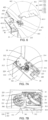
- the refrigerator 1 includes a box body 10, a door body 20 and a hinge assembly 30.
- the box body 10 includes an inner container, an outer shell and a heat insulation layer.
- the inner container has a substantially rectangular box shape, and a storage compartment is defined therein.
- a shape of the outer shell matches the shape of the inner container, and the inner container is disposed in the outer shell.
- the heat insulation layer is disposed between the inner container and the outer shell, so as to block the heat transfer between the storage compartment and the outer space of the box body 10.
- the refrigerator 1 further includes a cooling device, and the cooling device is configured to provide cool air to the storage compartment.
- a side e.g., a front side
- the storage compartment is configured to store food, and a user may put food into or take out food from the storage compartment through the access opening.
- the storage compartment may be divided into a refrigerating compartment and a freezing compartment.
- the refrigerating compartment may maintain the temperature of the air inside the refrigerating compartment at about 0°C to 5°C, and store food in a refrigerating mode.
- the freezing compartment may maintain the temperature of the air inside the freezing compartment at about -30°C to 0°C, and store food in a freezing mode.
- the box body 10 may further include other compartments, such as a vacuum compartment, a constant temperature compartment.
- the refrigerating compartment and the freezing compartment are disposed along a height direction of the refrigerator 1.
- the refrigerating compartment is located below the freezing compartment.
- the refrigerating compartment and the freezing compartment may be disposed in other ways, which is not limited in the present disclosure.
- the door body 20 is connected to an end (e.g., a front end) of the box body 10 through the hinge assembly 30.
- the door body 20 is rotatable, so as to open or close the storage compartment. In a case where the door body 20 is opened, the access opening allows food to be put in or taken out.
- the hinge assembly 30 is, for example, a first hinge assembly 40 or a second hinge assembly 50.
- the first hinge assembly 40 is disposed on an upper portion of the box body 10, and is fixedly connected to the box body 10 and the door body 20.
- the second hinge assembly 50 is disposed at a lower portion of the box body 10, and is fixedly connected to the box body 10 and the door body 20.
- the first hinge assembly 40 and the second hinge assembly 50 are disposed along a same axis, so that the door body 20 may rotate around the axis to implement the opening and closing of the door body 20.
- the hinge assembly 30 is located at a left side or a right side of the door body 20.
- the door body 20 includes a left side wall, a right side wall, an upper wall, a lower wall and a front side wall.
- the one closer to the hinge assembly 30 is referred to as a door side wall 21.
- the hinge assembly 30 is disposed at the left end of the door body 20 (i.e., the right side of the user), then the left side wall of the door body 20 is referred to as the door side wall 21, and the right end of the door body 20 rotates around the lift end of the door body 20 as a rotation center.
- the hinge assembly 30 is disposed at the right end of the door body 20
- the right side wall of the door body 20 is referred to as the door side wall 21
- the left end of the door body 20 rotates around the right end of the door body 20 as the rotation center.
- the door side wall 21 is flush with a side wall of the box body 10 proximate to the hinge assembly 30 (i.e., the box body side wall 12). It will be noted that the term “flush” includes both being completely flush and being approximately flush.
- a side wall (e.g., a front side wall) of the door body 20 away from the box body 10 in a case where the door body 20 is closed is referred to as the door front wall 22, and a side wall (e.g., a rear side wall) of the door body 20 proximate to the box body 10 in a case where the door body 20 is closed is referred to as the door rear wall 23.
- An intersection of the door front wall 22 and the door side wall 21 forms a first lateral edge W (i.e., a lateral edge), and an intersection of the door side wall 21 and the door rear wall 23 forms a second lateral edge N.
- the first lateral edge W is located at a side of the second lateral edge N away from the box body 10.
- an intersection line of the two planes is a theoretical first lateral edge W.
- the intersection of the door front wall 22 and the door side wall 21 is usually rounded to transition. In this way, the intersection of the door front wall 22 and the door side wall 21 forms a curved surface, and any straight line extending along the height direction (i.e., an upper-lower direction) of the refrigerator 1 on the curved surface may represent the first lateral edge W.
- the box body 10 includes a left side wall, a right side wall, an upper wall, a lower wall and a rear side wall.
- a plane where a side wall of the left side wall and the right side wall of the box body 10 proximate to the hinge assembly 30 is located is defined as a datum plane M0.
- a side where the box body 10 is located is defined as an inner side, and an opposite side is defined as an outer side.
- the hinge assembly 30 is disposed at the left end of the box body 10, then the left side wall of the box body 10 is defined as the datum plane M0, and the inner side is the right side of the datum plane M0.
- the hinge assembly 30 is disposed at the right end of the box body 10
- the right side wall of the box body 10 is defined as the datum plane M0
- the inner side is the left side of the datum plane M0.
- a width of the first gap 101 is usually any value within a range from 3mm to 5mm, for example, the width of the first gap 101 may be 3mm, 4mm, or 5mm.
- a distance i.e., as the door body 20 rotates, the distance between the first lateral edge W and the datum plane M0 when the first lateral edge W moves from the datum plane M0 to the outer side
- the distance should not be greater than 5mm. Otherwise, the first lateral edge W will collide with the cabinet 100, so that the door body 20 cannot be fully opened, and the door body 20 or the cabinet 100 will be damaged.
- the hinge assembly 30 is in a form of a double-shaft hinge, so that the first lateral edge W of the door body 20 will move towards the inner side in a case where the door body 20 is rotated, so as to prevent the first lateral edge W from colliding with the cabinet 100.
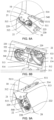
- the first hinge assembly 40 includes a first hinge plate 410, a first double-shaft assembly 420, a first trajectory groove 433 and a second trajectory groove 434.
- the first hinge plate 410 includes a first connecting portion 411 and a first extending portion 412 connected to the first connecting portion 411, the first connecting portion 411 and the first extending portion 412 are coplanar.
- the first double-shaft assembly 420 includes a first shaft 421 and a second shaft 422.
- the door body 20 includes a first end cover 210 disposed on the upper end of the door body 20 and corresponding to the position of the first hinge assembly 40.
- a surface of the first end cover 210 proximate to the first hinge plate 410 is recessed away from the first hinge plate 410 to form the first trajectory groove 433 and the second trajectory groove 434.
- the first end cover 210 is an injection molded member, which is integrally formed by injection molding.
- the first end cover 210 may be integrally formed with the door body, in this case, the first end cover 210 may be a portion of the door body.
- Both the first shaft 421 and the second shaft 422 of the first double-shaft assembly 420 are disposed on the first extending portion 412 and extend downwards from a lower surface of the first extending portion 412.
- the first shaft 421 is inserted in the first trajectory groove 433 and matched with the first trajectory groove 433.
- the second shaft 422 is inserted in the second trajectory groove 434 and matched with the second trajectory groove 434.
- the first connecting portion 411 is fixedly connected to the upper wall of the box body 10.
- the first connecting portion 411 has a plurality of first through holes 4111
- the box body 10 has a plurality of second through holes 11.
- the plurality of second through holes 11 are located in the upper wall of the box body 10 and correspond one-to-one with the plurality of first through holes 4111.
- the first connecting portion 411 may be fixedly connected to the box body 10 by fasteners such as screws.
- the box body 10 and the door body 20 are connected through the first hinge assembly 40, and the door body 20 may rotate relative to the box body 10 through the first hinge assembly 40.
- a diameter of the first shaft 421 is greater than a diameter of the second shaft 422.
- the first shaft 421 is a main shaft and mainly plays a positioning role
- the second shaft 422 is a secondary shaft and mainly plays a guiding role.
- the door body 20 When the door body 20 rotates, the door body 20 will exert force on the first shaft 421 and the second shaft 422, and the force is mainly concentrated on the main shaft. Therefore, in a case where the diameter of the first shaft 421 is greater than that of the second shaft 422, the strength of the first shaft 421 may be improved.
- the first connecting portion 411 is integrally formed with the first extending portion 412, and the first hinge plate 410, the first shaft 421 and the second shaft 422 are integrally formed.
- the first hinge plate 410, the first shaft 421 and the second shaft 422 may be independent members, and the first shaft 421 and the second shaft 422 may be fixedly connected to the first hinge plate 410 by welding or screwing.
- the first hinge assembly 40 further includes a first mounting block 430, and the first mounting block 430 includes a first board body 431 and a first protruding portion 432.
- the first board body 431 extends downwards to form a first protruding portion 432, and the first protruding portion 432 opens upwards to define the first trajectory groove 433 and the second trajectory groove 434.
- the first trajectory groove 433 includes a groove bottom and a circumferential groove wall surrounding the edge of the groove bottom.
- the circumferential groove wall encloses a groove opening opposite to the groove bottom.
- a structure of the second trajectory groove 434 is similar to that of the first trajectory groove 433 except for length and shape of the groove.
- the first end cover 210 includes a first accommodating groove 213, and the first accommodating groove 213 is open upwards.
- the first mounting block 430 is embedded in the first accommodating groove 213.
- the first board body 431 is parallel to the upper wall of the door body 20.
- the first board body 431 has a plurality of third through holes 4311
- the first end cover 210 has a plurality of fourth through holes 214
- the plurality of fourth through holes 214 are in one-to-one correspondence with the plurality of third through holes 4311.
- the first board body 431 and the first end cover 210 may be fixedly connected by fasteners such as screws.
- the first board body 431 includes a first clamping notch.
- the first accommodating groove 213 includes a first clamping portion.
- the first clamping portion is installed in the first clamping notch, so that the relative position of the first mounting block 430 and the door body 20 may be limited.
- the first board body 431 and the first protruding portion 432 are integrally formed, so that the structural accuracy and the strength of the first mounting block 430 may be improved.
- first board body 431 and the first protruding portion 432 may be integrally formed by injection molding.
- the second hinge assembly 50 includes a second hinge plate 510, a second double-shaft assembly 520, a third trajectory groove 533 and a fourth trajectory groove 534.
- the second hinge plate 510 includes a second connecting portion 511 and a second extending portion 512 connected to the second connecting portion 511.
- the second double-shaft assembly 520 includes a third shaft 521 and a fourth shaft 522.
- the door body 20 further includes a second end cover 220, and the second end cover 220 is disposed on the lower end of the door body 20 and corresponds to the position of the second hinge assembly 50.
- a surface of the second end cover 220 proximate to the second hinge plate 510 is recessed away from the second extending portion 512 to form the third trajectory groove 533 and the fourth trajectory groove 534.
- the second end cover 220 is an injection molded member, which is integrally formed by injection molding.
- the second end cover 220 may be integrally formed with the door body, in this case, the second end cover 220 may be a portion of the door body.
- the second connecting portion 511 is connected to a side of the lower end of the box body 10 proximate to the door body 20.
- the second extending portion 512 extends from the second connecting portion 511 towards a direction away from the box body 10.
- the second connecting portion 511 has a plurality of fifth through holes 5111, and the box body 10 has a plurality of sixth through holes.
- the plurality of sixth through holes are located in the lower wall of the box body 10 and are in one-to-one correspondence with the plurality of fifth through holes 5111.
- the second connecting portion 511 may be fixedly connected to the box body 10 by fasteners such as screws.
- Both the third shaft 521 and the fourth shaft 522 of the second double-shaft assembly 520 are disposed on the second extending portion 512 and extend upwards from the upper surface of the second extending portion 512.
- the third shaft 521 is inserted in the third trajectory groove 533 and matched with the third trajectory groove 533.
- the fourth shaft 522 is inserted in the fourth trajectory groove 534 and matched with the fourth trajectory groove 534. In this way, the box body 10 and the door body 20 are connected through the second hinge assembly 50, and the door body 20 may rotate relative to the box body 10 through the second hinge assembly 50.
- a diameter of the third shaft 521 is greater than a diameter of the fourth shaft 522.
- the third shaft 521 is a main shaft, which mainly plays a positioning role
- the fourth shaft 522 is a secondary shaft, which mainly plays a guiding role.
- the door body 20 rotates, the door body 20 exerts force on the third shaft 521 and the fourth shaft 522, and the force is mainly concentrated on the main shaft. Therefore, in a case where the diameter of the third shaft 521 is greater than that of the fourth shaft 522, the strength of the third shaft 521 may be improved.
- the second connecting portion 511 is integrally formed with the second extending portion 512, and the second hinge plate 510, the third shaft 521 and the fourth shaft 522 are integrally formed.
- the second hinge plate 510, the third shaft 521 and the fourth shaft 522 may be independent members, and the third shaft 521 and the fourth shaft 522 may be fixedly connected to the second hinge plate 510 by welding or screwing.
- the second hinge assembly 50 further includes a second mounting block 530
- the second mounting block 530 includes a second board body 531 and a second protruding portion 532.
- the second board body 531 extends downwards to form the second protruding portion 532, and the second protruding portion 532 opens downwards to define the third trajectory groove 533 and the fourth trajectory groove 534.
- the third trajectory groove 533 includes a groove bottom and a circumferential groove wall surrounding the edge of the groove bottom.
- the circumferential groove wall encloses a groove opening opposite to the groove bottom.
- a structure of the fourth trajectory groove 534 is similar to that of the third trajectory groove 533 except for length and shape of the groove.
- the second end cover 220 includes a second accommodating groove 223, and the second accommodating groove 223 is open downwards.
- the second mounting block 530 is embedded in the second accommodating groove 223.
- the second board body 531 is parallel to the lower wall of the door body 20.
- the second board body 531 has a plurality of seventh through holes 5311
- the second end cover 220 has a plurality of eighth through holes 224
- the plurality of eighth through holes 224 are in one-to-one correspondence with the plurality of seventh through holes 5311.
- the second board body 531 and the second end cover 220 may be fixedly connected by fasteners such as screws.
- the second board body 531 includes a second clamping notch.
- the second accommodating groove 223 includes a second clamping portion.
- the second clamping portion is installed in the second clamping notch, so that the relative position of the second mounting block 530 and the door body 20 may be limited.
- the second board body 531 and the second protruding portion 532 are integrally formed, so that the structural accuracy and the strength of the second mounting block 530 may be improved.
- the second board body 531 and the second protruding portion 532 may be integrally formed by injection molding.
- the second hinge plate 510 further includes a first fit portion
- the second mounting block 530 further includes a second fit portion matched with the first fit portion.
- the first fit portion is matched with the second fit portion to limit the door body 20.
- the first fit portion is disengaged from the second fit portion, so that the door body 20 rotates away from the box body 10.
- the second fit portion is configured as a locking hook 540.
- the locking hook 540 is disposed on a side (e.g., the left side or the right side) of the second board body 531.
- a fixed end of the locking hook 540 is fixedly connected to the second board body 531, and a free end of the locking hook 540 extends away from the second board body 531 and bends towards a direction proximate to the second board body 531, thereby forming an opening 541 facing towards the second board body 531.
- the free end of the locking hook 540 is closer to the box body 10 than the fixed end of the locking hook 540.
- the first fit portion is configured as a blocking portion 513.
- the blocking portion 513 is disposed on a side (e.g., left or right) of the second extending portion 512, and the blocking portion 513 extends from the side of the second extending portion 512 towards a direction away from the second extending portion 512.
- a second gap 514 is defined between the blocking portion 513 and the second connecting portion 511.
- a position of the blocking portion 513 corresponds to a position of the opening 541, that is, in a case where the locking hook 540 is disposed at the left side of the second board body 531, the blocking portion 513 is disposed at the left side of the second extending portion 512. Conversely, in a case where the locking hook 540 is disposed at the right side of the second board body 531, the blocking portion 513 is disposed at the right side of the second extending portion 512.
- the blocking portion 513 is located in the opening 541.
- the free end of the locking hook 540 is located in the second gap 514, and abuts against a side of the blocking portion 513 proximate to the box body 10, thereby improving the tightness of the fit between the door body 20 and the box body 10, and preventing the effect of refrigeration and freezing of the refrigerator from being affected due to the lax closing of the door body 20.
- the locking hook 540 will be deformed under force to overcome the blocking of the blocking portion 513, so that the locking hook 540 is disengaged from the blocking portion 513.
- the locking hook 540 includes a third extending portion 542 and a bending portion 543.
- the third extending portion 542 is connected to a side (e.g., the left side or the right side) of the second board body 531, and the third extending portion 542 is integrally formed with the second board body 531.
- An end of the bending portion 543 is fixedly connected to an end of the third extending portion 542 away from the second board body 531, and another end of the bending portion 543 extends away from the second board body 531 and is bent towards a direction proximate to the second plate body 531.
- the third extending portion 542 has a ninth through hole 5421, and the second end cover 220 has a tenth through hole 225 at a position corresponding to the ninth through hole 5421.
- the third extending portion 542 may be connected to the second end cover 220 by a fastener such as a screw, which is conducive to improving the connection strength between the third extending portion 542 and the second end cover 220, so that only the bending portion 543 is deformed when the locking hook 540 is disengaged from the blocking portion 513.
- free ends of the bending portion 543 and the blocking portion 513 are arc-shaped, which is conducive to improving the smoothness of the engagement or disengagement of the bending portion 543 and the blocking portion 513.
- the door body 20 in a case where the door body 20 is closed to a preset closing angle from an open state, the door body 20 is closed under the action of the bending portion 543 and the blocking portion 513.
- the preset closing angle is less than 7°.
- the second end cover 220 further includes a first protrusion 226 and a second protrusion 227.
- a gap groove 228 is formed between the first protrusion 226 and the second protrusion 227.
- the first protrusion 226 is closer to the door front wall 22 and closer to the door side wall 21 than the second protrusion 227.
- the third extending portion 542 further includes an inserting plate 5422.
- the inserting plate 5422 is located at an end of the third extending portion 542 proximate to the bending portion 543, and a shape of the inserting plate 5422 matches a shape of the gap groove 228.
- the inserting plate 5422 is inserted into the gap groove 228, so that the third extending portion 542 may be limited, and the third extending portion 542 may be prevented from deforming in a thickness direction of the door body 20.
- the gap groove 228 is an arc-shaped groove
- the inserting plate 5422 is an arc-shaped plate matched with the gap groove 228, so that the contact area between the gap groove 228 and the third extending portion 542 may be increased, which is conducive to improving the connection strength between the second mounting block 530 and the second end cover 220.
- the tenth through hole 225 is formed in the first protrusion 226.
- the locking hook 540 may be disposed on at least one of the first mounting block 430 and the second mounting block 530, and the blocking portion 513 is disposed on at least one of the first hinge plate 410 and the second hinge plate 510 corresponding to the locking hook 540.
- any mounting block including at least one of the first mounting block 430 and the second mounting block 530
- the shape of the corresponding accommodating groove is also changed to accommodate the mounting block.
- the mounting block is made of Polyformaldehyde (POM).
- POM Polyformaldehyde
- the second end cover 220 further includes a limiting portion 229.
- the limiting portion 229 is disposed in the second end cover 220 and protrudes downwards from the lower surface of the second end cover 220.
- the limiting portion 229 extends along the width direction of the door body 20.
- the limiting portion 229 is located at the front end of the second mounting block 530.
- the limiting portion 229 is a sheet metal member.
- the second hinge plate 510 further includes a limiting groove 515.
- the limiting groove 515 is located at a position of the second extending portion 512 proximate to the door side wall 21 and proximate to the door front wall 22, and runs through the second extending portion 512 along a thickness direction of the second extending portion 512.
- the limiting portion 229 is against the limiting groove 515 to prevent the door body 20 from continuing to rotate, thereby preventing the fourth shaft 522 from rubbing against an end of the fourth trajectory groove 534 proximate to the door side wall 21, which is conducive to improving the durability of the fourth shaft 522.
- the limiting portion 229 includes an embedding portion 2291 and a limiting bar 2292.
- the embedding portion 2291 is plate-shaped, and is embedded between the second mounting block 530 and the groove wall of the second accommodating groove 223. That is to say, in a case where the second mounting block 530 is embedded in the second accommodating groove 223, a side of the second board body 531 proximate to the door front wall abuts against the embedding portion 2291, so as to fix the embedding portion 2291 in the second accommodating groove 223.
- the limiting bar 2292 is connected to the embedding portion 2291 and is located at a lower side of the embedding portion 2291.
- the limiting bar 2292 extends along the width direction of the door body 20. In a case where the door body 20 is rotated to the maximum angle, the limiting bar 2292 abuts against the limiting groove 515, thereby preventing the door body 20 from continuing to rotate.
- the limiting bar 2292 is integrally formed with the embedding portion 2291.
- the limiting portion 229 is fixedly installed in the second accommodating groove 223 through the clamping of the second mounting block 530 and an inner side wall of the second accommodating groove 223, so that the connection structure between the limiting portion 229 and the second end cover 220 may be simplified.
- the limiting portion 229 may also be disposed in the first end cover 210, which will not be repeated here.
- the first shaft 421 is in clearance fit with the first trajectory groove 433, and the second shaft 422 is in clearance fit with the second trajectory groove 434, so that the deformation caused by manufacturing errors may be released.
- the third shaft 521 is interference fit with the third trajectory groove 533, and the fourth shaft 522 is interference fit with the fourth trajectory groove 534, so as to prevent abnormal noise when the locking hook 540 and the blocking portion 513 are disengaged, and implement silent opening of door body 20.
- the first lateral edge W exceeds the datum plane M0 and moves to the outer side by no more than 5 mm, it is necessary to make the first edge W move towards the inner side of the datum plane M0 during the rotation of the door body 20, so as to satisfy the requirement of inserting the refrigerator 1 into the cabinet 100 for use.
- the process of opening or closing the door body 20 relative to the box body 10 will be introduced below mainly by taking the first hinge assembly 40 disposed on the upper portion of the box body 10 as an example. It can be understood that the working principle of the second hinge assembly 50 is the same as that of the first hinge assembly 40, which will not be repeated in this disclosure.
- first hinge plate 410 After the first hinge plate 410 is fixedly connected to the box body 10, and the first shaft 421 and the second shaft 422 are fixedly connected to the first hinge plate 410, during the rotation of the door body 20 relative to the box body 10, the box body 10 remains stationary, therefore, the first hinge plate 410, the first shaft 421 and the second shaft 422 also remain stationary. In this case, the first trajectory groove 433 will move relative to the first shaft 421, and the second trajectory groove 434 will move relative to the second shaft 422.
- first trajectory groove 433 and the second trajectory groove 434 as stationary reference objects, describing a manner in which the first shaft 421 moves in the first trajectory groove 433 and the second shaft 422 moves in the second trajectory groove 434.
- the first trajectory groove 433 includes a straight groove segment and a curved groove segment connecting the straight groove segment.
- the straight groove segment is farther away from the door side wall 21 than the curved groove segment.
- an end of the straight groove segment is farther from the door side wall 21 than another end of the straight groove segment, that is, the straight groove segment is parallel to the door front wall 22.
- An end of the curved groove segment communicates with the other end of the straight groove segment, and another end of the curved groove segment extends towards the door side wall 21 and the door front wall 22.
- the curved groove segment protrudes towards a direction proximate to the door side wall 21 and proximate to the door rear wall 23, in this case, the second lateral edge N is located at a convex side of the curved groove segment.
- a center trajectory line of the first trajectory groove 433 is referred to as a first trajectory line S. It can be understood that the first trajectory line S is defined by the shape of the first trajectory groove 433. Corresponding to the straight groove segment and the curved groove segment, the first trajectory line S includes a straight trajectory segment and a curved trajectory segment connected to the straight trajectory segment.
- An end of the straight trajectory segment is farther away from the door side wall 21 than another end of the straight trajectory segment, an end of the curved trajectory segment is connected to the other end of the straight trajectory segment, and another end of the curved trajectory segment extends in a direction proximate to the door side wall 21 and proximate to the door front wall 22.
- the second lateral edge N is located at a convex side of the curved trajectory segment.
- a connection point of the straight trajectory segment and the curved trajectory segment is referred to as a second positioning point P 2 (see FIG. 15B ), and the straight trajectory segment is tangent to the curved trajectory segment at the point P 2 .
- the first shaft 421 moves in the first trajectory groove 433 from the one end of the straight trajectory segment to the second positioning point P 2 along the straight trajectory segment, and then moves along the curved trajectory segment.
- the second trajectory groove 434 is a quasi elliptical arc groove. An end of the second trajectory groove 434 is farther away from the door side wall 21 and closer to the door front wall 22 than another end of the second trajectory groove 434. In some embodiments, the second trajectory groove 434 protrudes towards a direction away from the door side wall 21 and away from the door front wall 22, in this case, the first lateral edge W is located at a concave side of the second trajectory groove 434.
- a center trajectory line of the second trajectory groove 434 is referred to as a second trajectory line K.
- the second trajectory line K is in a shape of a quasi elliptical arc.
- An end of the second trajectory line K is farther from the door side wall 21 and closer to the door front wall 22 than another end of the second trajectory line K, and the first lateral edge W is located at a concave side of the second trajectory line K.
- the first trajectory groove 433 is located at the concave side of the second trajectory groove 434.
- the first shaft 421 relatively moves in a straight line in the straight trajectory segment
- the second shaft 422 relatively moves in a curve in the second trajectory groove 434, so that the door body 20 may move a certain distance to the inner side of the datum plane M0 while rotating. In this way, the door body 20 may be prevented from colliding with the cabinet 100 when opened.
- the quasi elliptical arc groove is a groove having a center trajectory line (e.g., the second trajectory line K) of a quasi elliptical.
- the arc of the quasi elliptical includes a standard elliptical arc (i.e., a portion of a standard ellipse), and a non-standard elliptical arc that is different from the standard elliptical arc but still has elliptical arc trajectory characteristics due to manufacturing, assembly errors, or slight deformation.
- both the first shaft 421 and the second shaft 422 are cylindrical.
- An orthogonal projection of a central axis of the first shaft 421 on the first trajectory groove 433 is referred to as a positioning center point P
- an orthogonal projection of a central axis of the second shaft 422 on the second trajectory groove 434 is referred to as a guiding center point Q.
- X represents a distance between the change point and the door side wall 21, and Y represents a distance between the change point and the door front wall 22.
- X 1 represents a distance between the positioning center point P and the door side wall 21, and Y 1 represents a distance between the positioning center point P and the door front wall 22.
- X 2 represents a distance from the guiding center point Q to the door side wall 21, and Y2 represents a distance from the guiding center point Q to the door front wall 22.
- the second trajectory line K is an elliptical arc.
- c is a distance between a center of an ellipse O and the door side wall 21
- d is a distance between the center of the ellipse O and the door front wall 22
- ⁇ is an inclination angle of the ellipse
- t is a parameter
- f is a major half axis of the ellipse
- g is a minor half axis of the ellipse.
- the distance between the positioning center point P and the door side wall 21 is a
- the distance between the positioning center point P and the door front wall 22 is b
- the distance between the positioning center point P and the guiding center point Q is L.
- the included angle formed by a line connecting the positioning center point P and the guiding center point Q (axis line segment PQ) and the plane where the door front wall 22 is located is n.
- the first shaft 421 moves a distance k towards a direction proximate to the door side wall 21.
- a point Q' is an end point of the second trajectory line K.
- V 1 + h 2 [ X Q + X Q ′ 2 ⁇ 4 ⁇ X Q ⁇ X Q ′ , X Q can be obtained.
- X Q represents a distance from the guiding center point Q to the door side wall 21
- X Q' represents a distance from an end point Q' of the second trajectory line K to the door side wall 21.
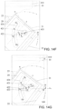
- FIGS. 14A to 14J show structural diagrams of the first hinge assembly 40 when the door body 20 is opened to different angles. It can be understood that the first shaft 421 moves along the first trajectory groove 433, which is equivalent to the positioning center point P moving along the first trajectory line S. In addition, The second shaft 422 moves along the second trajectory groove 434, which is equivalent to the guiding center point Q moving along the second trajectory line K.
- the first trajectory line S includes an initial positioning point P 0 and a seventh positioning point P 7 that is closer to the door side wall 21 and closer to the door front wall 22 than the initial positioning point P 0 .
- the first trajectory line S extends from the initial positioning point P 0 towards a direction proximate to the door side wall 21, and then extends in a certain arc towards a direction proximate to the door side wall 21 and proximate to the door front wall 22 to the seventh positioning point P 7 .
- the seventh positioning point P 7 is the other end of the first trajectory line S.
- the second trajectory line K includes a guiding initial point Q 0 and a ninth guiding point Q 9 that is closer to the door side wall 21 and farther from the door front wall 22 than the guiding initial point Q 0 .
- the second trajectory line K extends from the guiding initial point Q 0 to the ninth guiding point Q 9 in a direction proximate to the door side wall 21 and away from the door front wall 22, and the second trajectory line K is substantially in the shape of a quasi elliptical.
- the first trajectory line S is closer to the door front wall 22 and closer to the door side wall 21 than the second trajectory line K, that is, the first trajectory line S is located at the concave side of the second trajectory line K.
- the second trajectory groove 434 may effectively limit the movement of the second shaft 422 and cooperate with the movement of the first shaft 421 in the first trajectory groove 433. Therefore, during the opening process of the door body 20, the first shaft 421 is driven by the second shaft 422 to move, and the door body 20 moves a certain distance to the inner side while rotating, so as to ensure the stability of the door body 20 when opened.
- the maximum opening angle G 9 of the refrigerator is greater than 90° (i.e., G 9 >90°) as an example, providing a detailed description of the positions of the first shaft 421 relative to the first trajectory groove 433 and the second shaft 422 relative to the second trajectory groove 434 when the door body 20 rotates and opens to different angles during the process of the door body 20 being opened from the closed state to the maximum angle G 9 .
- centroid plane F a plane passing through the centroid of the door body 20 and parallel to the door front wall 22.
- centroid plane F a plane passing through the centroid of the door body 20 and parallel to the door front wall 22.
- the positioning center point P is located at the initial positioning point P 0 of the first trajectory line S
- the guiding center point Q is located at the guiding initial point Q 0 of the second trajectory line K.
- the guiding center point Q and the positioning center point P are located at the same side of the centroid plane F, and the guiding center point Q is farther away from the centroid plane F than the positioning center point P.
- the first shaft 421 moves along the straight trajectory segment of the first trajectory line S towards the direction proximate to the door side wall 21
- the second shaft 422 moves along the second trajectory line K towards the direction proximate to the door side wall 21 and away from the door front wall 22.
- the guiding center point Q and the positioning center point P are located at the same side of the centroid plane F, and the guiding center point Q is farther away from the centroid plane F than the positioning center point P.
- any opening angle greater than 0° and less than G 2 is chosen to represent the relative positions of the first shaft 421 with respect to the first trajectory groove 433 and the second shaft 422 with respect to the second trajectory groove 434 when the door body 20 is opened to the corresponding range.
- the opening angle of the door body 20 is G 1 (for example, G 1 is greater than 0° and less than G 2 ) to represent the positions within the opening angle range, so as to compare with the positions when the door body 20 is opened to other angles.
- the positioning center point P is located at the first positioning point P 1 of the first trajectory line S, and the first positioning point P 1 is closer to the door side wall 21 than the initial positioning point P 0 .
- the guiding center point Q is located at the first guiding point Q 1 of the second trajectory line K, and the first guiding point Q 1 is closer to the door side wall 21 and farther away from the door front wall 22 than the initial guiding point Q 0 .
- the door body 20 is rotated to open to G 2 .
- the positioning center point P is located at the second positioning point P 2 on the straight trajectory segment of the first trajectory line S, and the second positioning point P 2 is closer to the door side wall 21 than the first positioning point P 1 .
- the second positioning point P 2 is an end point of the straight trajectory segment proximate to the door side wall 21.
- the guiding center point Q is located at the second guiding point Q 2 of the second trajectory line K, and the second guiding point Q 2 is closer to the door side wall 21 and farther away from the door front wall 22 than the first guiding point Q 1 .
- the first shaft 421 moves along the straight groove segment towards the direction proximate to the door side wall 21, and the second shaft 422 moves along the second trajectory groove 434 towards the direction proximate to the door side wall 21 and away from the door front wall 22.
- G 2 may be set to any value from 13° to 17°.
- G 2 may be 13°, 14°, 15° or 17°.
- the guiding center point Q and the positioning center point P are located at the same side of the centroid plane F, and the guiding center point Q is closer to the centroid plane F than the positioning center point P.
- the first fit portion is disengaged from the second fit portion.
- the locking hook 540 is disengaged from the blocking portion 513.
- the unlocking angle is set to G 1 , that is, in a case where the door body 20 is opened to G 1 , the locking hook 540 is disengaged from the blocking portion 513.
- the unlocking angle is set to G 2 , that is, in a case where the door body 20 is opened to G 2 , the locking hook 540 is disengaged from the blocking portion 513.
- the door body 20 moves a short distance towards the inner side for each unit of rotational angle, which is conducive to implementing rapid separation between the locking hook 540 and the blocking portion 513, and improving the smoothness of opening the door body 20.
- the first shaft 421 moves along the curved trajectory segment of the first trajectory line S towards the direction proximate to the door side wall 21 and proximate to the door front wall 22, and the second shaft 422 moves along the second trajectory line K towards a direction proximate to the door side wall 21 and away from the door front wall 22.
- any opening angle greater than G 2 and less than G 7 is chosen to represent the relative positions of the first shaft 421 with respect to the first trajectory groove 433 and the second shaft 422 with respect to the second trajectory groove 434 when the door body 20 is opened to the corresponding range.
- G 3 , G 4 , G 5 , and G 6 are used to represent the positions in the opening angle range, so as to compare with the positions when the door body 20 is opened to other angles.
- the positioning center point P moves along the first trajectory line S towards the direction proximate to the door side wall 21 and proximate to the door front wall 22 to reach a positioning point P 3 , a fourth positioning point P 4 , a fifth positioning point P 5 , and a sixth positioning point P 6 .
- the guiding center point Q moves along the second trajectory line K towards a direction proximate to the door side wall 21 and away from the door front wall 22 to reach a third guiding point Q 3 , a fourth guiding point Q 4 , a fifth guiding point Q 5 and a sixth guiding point Q.
- G 3 is any value in a range from 22° to 30°.
- the third angle G 3 is 22°, 25°, 28° or 30°.
- G 4 is any value in a range from 43° to 47°.
- G 4 is 43°, 45°, or 47°.
- the distance between the first lateral edge W and the datum plane M0 reaches a maximum value.
- the distance between the first lateral edge W and the datum plane M0 is less than the width of the first gap 101, thereby effectively preventing the door body 20 from colliding with the cabinet 100 during opening.
- G 5 is any value in a range from 46° to 50°.
- G 5 is 46°, 48° or 50°, that is, in a case where the door body 20 is opened to about 48°, the distance between the first lateral edge W and the datum plane M0 reaches the maximum.
- a straight line Q 0 -Q 9 (the straight line where the two ends of the second trajectory line K are located) where the initial guiding point Q 0 and the ninth guiding point Q 9 are located is substantially parallel to the datum plane M0. That is, a perpendicular bisector line L 0 of a line segment Q 0 Q 9 is approximately perpendicular to the datum plane M0.
- approximately perpendicular is defined as an angle between the perpendicular bisector line L 0 and the datum plane M0 that is any value in a range from 88° to 92°.
- the above setting defines the extension direction of the second trajectory groove 434, so that, during the opening process of the door body 20, the synchronous movement of the first shaft 421 relative to the first trajectory groove 433 and the second shaft 422 relative to the second trajectory groove 434 is smoother, which is conducive to improving the fluency and stability of opening the door body 20.
- the included angle between a straight line containing the major axis of the ellipse where the second trajectory line K is located and the datum plane M0 is G 6 , which is conducive to improving the smoothness of opening the door body 20.
- the straight line where the line segment Q 0 Q 9 is located is parallel to the major axis of the ellipse where the second trajectory line K is located, so that the curvature of the second trajectory line K changes more gently, which is conducive to improving the smoothness of the movement of the second shaft 422 along the second trajectory groove 434.
- G 6 is equal to or proximate to G 9 /2.
- G 6 E [G 9 /2-6°, G 9 /2].
- the guiding center point Q moves to the midpoint of the second trajectory line K. In this way, during the opening process of the door body 20, the movement trajectory of the second shaft 422 relative to the second trajectory groove 434 is more stable, which is conducive to improving the smoothness of opening the door body 20.
- G 9 is any value in a range from 112° to 120°, for example, G 9 is 112°, 115°, 118° or 120°.
- G 6 is any value in a range from 50° to 60°, for example, G 6 is 50°, 53°, 56° or 60°.
- the centroid plane F of the door body 20 is located between the positioning center point P and the guiding center point Q.
- the positioning center point P is located at the seventh positioning point P 7 on the first trajectory line S, and the guiding center point Q is located at the seventh guiding point Q 7 on the second trajectory line K.
- the seventh positioning point P 7 is closer to the door side wall 21 and closer to the door front wall 22 than the sixth positioning point P 6
- the seventh guiding point Q 7 is closer to the door side wall 21 and farther from the door front wall 22 than the sixth guiding point Q 6 .
- the positioning center point P moves to the other end of the curved trajectory segment of the first trajectory line S.
- the centroid plane F of the door body 20 is located between the positioning center point P and the guiding center point Q.
- G 7 may be set to any value in a range from 63° to 67°.
- G 7 may be 63°, 64°, 65° or 67°.
- the first shaft 421 moves along the curved trajectory segment of the first trajectory line S towards the direction proximate to the door side wall 21 and proximate to the door front wall 22, and the second shaft 422 moves along the second trajectory line K towards a direction proximate to the door side wall 21 and away from the door front wall 22.
- any opening angle greater than G 7 and less than or equal to G 9 is chosen to represent the relative positions of the first shaft 421 with respect to the first trajectory groove 433 and the second shaft 422 with respect to the second trajectory groove 434 when the door body 20 is opened to the range.
- G 8 and G 9 are used to represent the positions within the opening angle range, for comparison with the positions when the door body 20 is opened to other states.
- G 7 ⁇ G 8 90° ⁇ G 9 .
- the positioning center point P is located at the eighth positioning point P 8 on the first trajectory line S, and the guiding center point Q is located at the eighth guiding point Q 8 on the second trajectory line K.
- the eighth positioning point P 8 is farther away from the door side wall 21 and away from the door front wall 22 than the seventh positioning point P 7
- the eighth guiding point Q 8 is closer to the door side wall 21 and farther away from the door front wall 22 than the seventh guiding point Q 7 .
- the centroid plane F is located between the positioning center point P and the guiding center point Q.
- the positioning center point P is located at the ninth positioning point P 9 on the first trajectory line S, and the guiding center point Q is located at the ninth guiding point Q 9 on the second trajectory line K.
- the ninth positioning point P 9 is farther away from the door side wall 21 and away from the door front wall 22 than the eighth positioning point P 8
- the ninth guiding point Q 9 is closer to the door side wall 21 and farther away from the door front wall 22 than the eighth guiding point Q 8 .
- the centroid plane F is located between the positioning center point P and the guiding center point Q.
- G 1 , G 2 , G 3 , G 4 , G 5 , G 6 , G 7 , G 8 , and G 9 are sequentially referred to as a first angle G 1 , a second angle G 2 , a third angle G 3 , a fourth angle G 4 , a fifth angle G 5 , a sixth angle G 6 , a seventh angle G 7 , an eighth angle G 8 and a maximum angle G 9 .
- the initial positioning point P 0 , the first positioning point P 1 and the second positioning point P 2 are distributed along the straight trajectory segment towards the direction proximate to the door side wall 21, the third positioning point P 3 , the fourth positioning point P 4 , the fifth positioning point P 5 , the sixth positioning point P 6 and the seventh positioning point P 7 are distributed along the curved trajectory segment towards the direction proximate to the door side wall 21 and proximate to the door front wall 22.
- the seventh positioning point P 7 , the eighth positioning point P 8 and the ninth positioning point P 9 are distributed along the curved trajectory segment towards the direction away from the door side wall 21 and away from the door front wall 22.
- the present disclosure does not limit the relative positions of the ninth positioning point P 9 and the eighth positioning point P 8 with the third positioning point P 3 , the fourth positioning point P 4 , the fifth positioning point P 5 and the sixth positioning point P 6 .
- the eighth positioning point P 8 is located between the sixth positioning point P 6 and the seventh positioning point P 7
- the ninth positioning point P 9 is proximate to the third positioning point P 3 .
- the initial guiding point Q 0 , the first guiding point Q 1 , the second guiding point Q 2 , the third guiding point Q 3 , the fourth guiding point Q 4 , the fifth guiding point Q 5 , the sixth guiding point Q 6 , the seventh guiding point Q 7 , the eighth guiding point Q 8 and the ninth guiding point Q 9 are distributed along the first trajectory line S towards the direction proximate to the door side wall 21 and away from the door front wall 22 in sequence.
- the first shaft 421 moves towards the door side wall 21 along the straight groove segment of the first trajectory groove 433.
- the first shaft 421 moves along the first trajectory groove 433 in the direction proximate to the door side wall 21 to the other end (the second positioning point P 2 ) of the straight groove segment.
- the first shaft 421 moves along the curved groove segment of the first trajectory groove 433 towards the direction proximate to the door side wall 21 and proximate to the door front wall 22.
- the first shaft 421 moves along the first trajectory groove 433 towards the direction proximate to the door side wall 21 and proximate to the door front wall 22 to the other end (the seventh positioning point P 7 ) of the curved groove segment.
- the first shaft 421 moves along the curved groove segment of the first trajectory groove 433 towards the direction away from the door side wall 21 and away from the door front wall 22.
- the second shaft 422 moves along the second trajectory groove 434 towards the direction proximate to the door side wall 21 and away from the door front wall 22.
- first shaft 421 and the second shaft 422 are fixed on the first hinge plate 410, and are stationary relative to the first hinge plate 410.
- the first trajectory groove 433 and the second trajectory groove 434 are disposed on the door body 20, and are stationary relative to the door body. Therefore, the movement of the axis line segment PQ relative to the trajectory groove (including the first trajectory groove 433 and the second trajectory groove 434) is equivalent to the movement of the first hinge plate 410 relative to the door body 20.
- the movement of the axis line segment PQ relative to the trajectory groove is also equivalent to the movement of the box body 10 relative to the door body 20.
- the movement of the door body 20 relative to the box body 10 may be obtained from the movement of the box body 10 relative to the door body 20.
- the movement of the box body 10 relative to the door body 20 will be represented by the movement of the axis line segment PQ relative to the door body 20 in the following description, and the movement of the door body 20 relative to the box body 10 is derived based on the principle of relative motion.
- the whole process of opening the door body 20 may be divided into three stages.
- the three stages will be described in detail with reference to the cooperation relationship between the first double-shaft assembly 420 and the trajectory grooves and the movement trajectory of the axis line segment PQ.
- the door body 20 is opened from 0° to the second angle G 2 through the first angle G 1 .
- the positioning center point P moves from the initial positioning point P 0 along the straight trajectory segment of the first trajectory line S towards the direction proximate to the door side wall 21, and the guiding center point Q moves from the initial guiding point Q 0 along the second trajectory line K towards the direction proximate to the door side wall 21 and away from the door front wall 22.
- the positioning center point P moves from the initial positioning point P 0 to the second positioning point P 2 through the first positioning point P 1 along the straight trajectory segment of the first trajectory line S.
- the guiding center point Q moves from the initial guiding point Q 0 to the second guiding point Q 2 through the first guiding point Q 1 along the second trajectory line K.
- the axis line segment PQ moves towards the outer side while rotating.
- the axis line segment PQ rotates clockwise from P 0 Q 0 and moves towards the outer side to P 1 Q 1 and P 2 Q 2 in sequence.
- first trajectory groove 433 and the second trajectory groove 434 are stationary relative to the door body 20
- the axis line segment PQ is stationary relative to the box body 10
- the movement of the axis line segment PQ may represent the movement of the box body 10. Therefore, in a case where the door body 20 is taken as a reference object, during the process of the door body 20 being opened from the closed state to the second angle G 2 , the box body 10 rotates clockwise relative to the door body 20 and moves towards the outer side for a certain distance.
- the door body 20 rotates counterclockwise relative to the box body 10 and moves towards the inner side for a certain distance.
- the first lateral edge W moves to the outer side due to the rotation of the door body 20
- the first lateral edge W further moves to the inner side due to the movement of the door body 20 to the inner side, thereby preventing the door body 20 from interfering with the cabinet 100.
- the door body 20 is opened from the second angle G 2 to the seventh angle G 7 through the third angle G 3 , the fourth angle G 4 , the fifth angle G 5 , and the sixth angle G 6 in sequence.
- the positioning center point P moves from the second displacement point P 2 to the seventh displacement point P 7 through the third displacement point P 3 , the fourth displacement point P 4 , the fifth displacement point P 5 and the sixth displacement point P 6 .
- the positioning center point P moves along the curved trajectory segment of the first trajectory line S towards the direction proximate to the door side wall 21 and proximate to the door front wall 22.
- the guiding center point Q moves from the second guiding point Q 2 to the seventh guiding point Q 7 through the third guiding point Q 3 , the fourth guiding point Q 4 , the fifth guiding point Q 5 and the sixth guiding point Q 6 .
- the guiding center point Q moves along the second trajectory line K towards the direction proximate to the door side wall 21 and away from the door front wall 22.
- the axis line segment PQ moves towards the outer side while rotating.
- the axis line segment PQ rotates clockwise from P 2 Q 2 and moves towards the outer side to P 3 Q 3 , P 4 Q 4 , P 5 Q 5 , P 6 Q 6 and P 7 Q 7 in sequence.
- first trajectory groove 433 and the second trajectory groove 434 are stationary relative to the door body 20
- the axis line segment PQ is stationary relative to the box body 10
- the movement of the axis line segment PQ may represent the movement of the box body 10. Therefore, in a case where the door body 20 is taken as a reference object, during the process of the door body 20 being opened from the second angle G 2 to the seventh angle G 7 , the box body 10 rotates clockwise relative to the door body 20 and moves along the curved trajectory segment towards the outer side and the front side (the direction proximate to the door body 20).
- the door body 20 rotates counterclockwise relative to the box body 10 and moves along the curved trajectory segment towards the inner side and the rear side (the direction proximate to the box body 10).
- the first lateral edge W moves to the outer side due to the rotation of the door body 20
- the first lateral edge W further moves to the inner side due to the movement of the door body 20 to the inner side, thereby preventing the door body 20 from interfering with the cabinet 100.
- the door body 20 further moves towards the direction proximate to the box body 10 while rotating, so that the door body 20 may be prevented from moving too much in the direction away from the box body 10 due to rotation, which is conducive to improving the integrity of door body 20 and box body 10.
- the door body 20 is opened from the seventh angle G 7 (about 90°) to the maximum angle G 9 through the eighth angle G 8 .
- the positioning center point P moves from the seventh displacement point P 7 to the ninth displacement point P 9 through the eighth positioning point P 8 .
- the positioning center point P moves along the curved trajectory segment of the first trajectory line S towards the direction away from the door side wall 21 and away from the door front wall 22.
- the guiding center point Q moves from the seventh guiding point Q 7 to the ninth guiding point Q 9 through the eighth guiding point Q 8 .
- the guiding center point Q moves along the second trajectory line K towards the direction proximate to the door side wall 21 and away from the door front wall 22.
- the first trajectory groove 433 and the second trajectory groove 434 are taken as reference objects, during the process of the door body 20 being opened from the seventh angle G 7 to the maximum angle G 9 , the axis line segment PQ moves towards the inner side while rotating clockwise.
- the axis line segment PQ rotates clockwise from P 7 Q 7 and moves towards the inner side to P 8 Q 8 and P 9 Q 9 in sequence.
- first trajectory groove 433 and the second trajectory groove 434 are stationary relative to the door body 20
- the axis line segment PQ is stationary relative to the box body 10
- the movement of the axis line segment PQ may represent the movement of the box body 10.
- the box body 10 rotates clockwise relative to the door body 20 and moves towards the inner side and the rear side (the direction away from the door body 20).
- the door body 20 rotates counterclockwise relative to the box body 10 and moves towards the outer side and the front side (the direction away from the box body 10).
- the door body 20 is opened from 90° to a greater angle (i.e., the maximum angle G 9 ) in the third stage, therefore, the first lateral edge W will not interfere with the cabinet 100, but there is still a possibility of interference with box body 10.
- the door body 20 is set to rotate counterclockwise relative to the box body 10 and move towards the outer side and the front side (the direction away from the box body 10), so that the first lateral edge W is driven by the door body 20 and moves towards the direction away from the box body 10, so as to prevent the first lateral edge W from interfering with the box body 10.
- the door body 20 since the door body 20 moves towards the outer side, the door body 20 may be opened to a greater angle in the third stage, and the door body 20 may be prevented from blocking the access opening.
- the door body 20 maintains a tendency to move towards the inner side. Relative to the closed state of the door body 20, when the door body 20 is opened to the seventh angle G 7 , the distance that the door body 20 moves to the inner side is referred to as a first distance D1.
- the distance that the door body 20 moves to the outer side is referred to as a second distance D2.
- the first distance D1 is greater than the second distance D2. That is, a lateral displacement of the door body 20 moving to the inner side first is greater than a lateral displacement of the door body 20 moving to the outer side afterwards.
- the door body 20 rotates around a dynamically changing axis.
- the dynamically changing axis first moves to the inner side for the first distance D1, and then moves to the outer side for the second distance D2, so that the door body 20 first moves to the inner side for the first distance D1, and then moves to the outer side for the second distance D2.
- the first shaft 421 moves relative to the first trajectory groove 433, and the second shaft 422 moves relative to the second trajectory groove 434.
- the relative positional relationship between the centroid plane F and the first shaft 421 and the second shaft 422 changes constantly.
- the first shaft 421 and the second shaft 422 are located at the same side of the centroid plane F.
- the centroid plane F is located between the first shaft 421 and the second shaft 422.
- the centroid plane F is located between the first shaft 421 and the second shaft 422, which is conducive to improving the stability of the door body 20 during the opening process.
- the midpoint of the axis line segment PQ is referred to as an axis center midpoint E.
- a distance between the axis center midpoint E and the centroid plane F is referred to as an offset distance I.
- the offset distance I is a positive number.
- the offset distance I is a negative number.
- the offset distance I is 0.
- the offset distance I between the axis center midpoint E and the centroid plane F is decreasing.
- the offset distances are referred to as I 4 , I 5 , I 6 , I 7 , I 8 and I 9 in sequence.
- the offset distance I between the axis center midpoint E and the centroid plane F is set to: as the opening angle of the door body 20 increases, the offset distance I decreases. That is, as the opening angle of the door body 20 increases, the centroid plane F moves accordingly and approaches the midpoint of the axis line segment PQ, thereby improving the stability of the door body 20 during opening.
- the axis center midpoint E is located on the centroid plane F, and the offset distance I is 0.
- the angle Ga is any value in a range from 110° to 116° (e.g., 110°, 113° or 116°).
- the centroid plane F is proximate to the axis center midpoint E (e.g., I 9 is any value in a range from -1mm to 1mm), which is conducive to improving the stability of the door body 20 when the door body 20 is opened to the maximum angle G 9 .
- the offset distance I is any value in a range from -4mm to 4mm (e.g., -4mm, 0 or 4 mm), so as to effectively improve the stability of the door body 20 when the door body 20 is opened to a relatively large angle (e.g., the door body is opened to an angle between the eighth angle G 8 and the maximum angle G 9 ).
- the first shaft 421 moves in a straight line along the straight groove segment of the first trajectory groove 433, and the door body 20 moves a third distance D3 (i.e., a first marginal distance) towards the inner side when the door body 20 is opened for a unit angle.
- the first shaft 421 moves along the curved groove segment of the first trajectory groove 433, and the door body 20 moves a fourth distance D4 (i.e., a second marginal distance) towards the inner side when the door body 20 is opened for a unit angle.
- the third distance D3 is greater than the fourth distance D4 (i.e., D3 > D4).
- the distance that the door body 20 moves towards the inner side is large when the door body 20 is opened for a unit angle, so that the door body 20 drives the first lateral edge W to move a greater distance towards the inner side. Therefore, the distance between the first lateral edge W and the datum plane M0 is less than the width of the first gap 101, so as to prevent the first lateral edge W from colliding with the cabinet 100.
- the first shaft 421 retreats along the first trajectory line S towards the direction away from the door side wall 21 and away from the door front wall 22.
- a stage in which the door body 20 is opened from the seventh angle G 7 to the eighth angle G 8 is referred to as a first retreat stage
- a stage in which the door body 20 is opened from the eighth angle G 8 to the maximum angle G 9 is referred to as a second retreat stage.
- the door body 20 moves a fifth distance D5 towards the outer side when the door body 20 is opened for a unit angle.
- the door body 20 moves a sixth distance D6 towards the outer side when the door body 20 is opened for a unit angle, and the sixth distance D6 is greater than the fifth distance D5.
- the fifth distance D5 the sixth distance D6 E [0.05, 0.1].
- the door body 20 is opened from the seventh angle G 7 (about 65°) to the eighth angle G 8 (about 90°), and the distance that the door body 20 moves towards the outer side when the door body 20 is opened for a unit angle is short, so as to prevent the door body 20 from exceeding the datum plane M0 too much in a case where the door body 20 is opened to 90°, so that the door body 20 may continue to open to a greater angle.
- the door body 20 is opened from 90° to the maximum angle G 9 , and the distance that the door body 20 moves towards the outer side when the door body 20 is opened for a unit angle is long, thereby preventing the door body 20 from blocking the access opening, which is conducive to improving the user experience when picking and placing foods.
- the positioning center point P is located at the ninth positioning point P 9 in a case where the door body 20 is opened to the maximum angle G 9 .
- the positioning center point P is located at the third positioning point P 3 in a case where the door body 20 is opened to the third angle G 3 .
- a difference between the maximum angle G 9 and the third angle G 3 is approximately 90°, and the ninth positioning point P 9 is proximate to the third positioning point P 3 .
- the difference between the maximum angle G 9 and the third angle G 3 is any value in a range from 88° to 92° (e.g., 88°, 90° or 92°).
- a distance between the ninth positioning point P 9 and the third positioning point P 3 is less than or equal to 1mm.
- the first shaft 421 first moves from the third positioning point P 3 towards the direction proximate to the door side wall 21 and proximate to the door front wall to the seventh positioning point P 7 , and then moves towards the direction away from the door side wall 21 and away from the door front wall 22 to the ninth positioning point P 9 proximate to the third positioning point P 3 . That is, during the process of the door body 20 is opened from the third angle G 3 to the maximum angle G 9 , the first shaft 421 approximately performs a back-and-forth motion.
- the first shaft 421 may perform the back-and-forth motion in the first trajectory groove 433, which is beneficial to lower the dimension of the first trajectory groove 433 in the thickness direction of the door body 20, thereby reducing the thickness of the door body 20.
- the second trajectory groove 434 includes a first curved groove and a second curved groove
- the second trajectory line K includes a first curved segment and a second curved segment.
- An end of the first curved segment is closer to the door front wall 22 and farther away from the door side wall 21 than another end of the first curved segment.
- An end of the second curved segment is connected to the other end of the first curved segment, and another end of the second curved segment extends towards the direction proximate to the door side wall 21 and away from the door front wall 22.
- the first lateral edge W is located at a concave side of the first curve segment and is located at a convex side of the second curve segment.
- the second shaft 422 moves in the second curved groove, and the guiding center point Q moves from the one end of the second curved segment to the other end of the second curved segment.
- the first shaft 421 moves in the first trajectory groove 433 simultaneously.
- the second trajectory groove 434 includes a third curved groove and a fourth curved groove
- the second trajectory line K includes a third curved segment and a fourth curved segment.
- An end of the third curved segment is closer to the door front wall 22 and farther away from the door side wall 21 than another end of the third curved segment.
- An end of the fourth curved segment is connected to the other end of the third curved segment, and another end of the fourth curved segment extends towards the direction proximate to the door side wall 21 and proximate to the door front wall 22.
- the first lateral edge W is located at a concave side of the third curve segment and is located at a concave side of the fourth curve segment.
- the second shaft 422 moves in the second curved groove, and the guiding center point Q moves from the one end of the fourth curved segment to the other end of the fourth curved segment.
- the first shaft 421 moves in the first trajectory groove 433 simultaneously.
- the positioning center point P of the first shaft 421 is located at the initial positioning point P 0 of the first trajectory line S, and a distance between the initial positioning point P 0 and the datum plane M0 is L 1 (i.e., a first preset distance).
- the door front wall 22 is approximately parallel to the plane where the access opening is located, and is approximately perpendicular to the datum plane M0.
- the door front wall 22 is approximately parallel to the box body side wall 12.
- the positioning center point P of the first shaft 421 is located at the eighth positioning point P 8 of the first trajectory line S, and a distance between the positioning center point P and the door front wall 22 is L 2 (i.e., a second preset distance).
- the door front wall 22 is approximately located in the datum plane M0. If L 1 is greater than L 2 , the door front wall 22 is located at the inner side of the datum plane M0. If L 1 is less than L 2 , the door front wall 22 is located at the outer side of the datum plane M0.
- L 1 and L 2 are set to be approximately equal or L 1 is set to be greater than L 2 . In this way, the door body 20 may be opened from 90° to a greater angle.
- L 1 and L 2 may further be set such that L 1 is less than L 2 , and the difference between L 2 and L 1 is less than 0.2 times the width of the first gap 101, so that the stability when the door body 20 is opened from 90° to a greater angle is improved.
- a plane located at the outer side of the datum plane M0 is defined as a first reference plane M1.
- the first reference plane M1 is parallel to the datum plane M0, and a distance between the first reference plane M1 and the datum plane M0 is the width (i.e., 3 mm to 5 mm) of the first gap 101.
- the first reference plane M1 is a plane where the inner wall of the cabinet 100 proximate to the datum plane M0 is located.
- a plane where the access opening is located is defined as a second reference plane M2, and the second reference plane M2 is perpendicular to the first reference plane M1.
- the first reference plane M1 and the second reference plane M2 remain stationary relative to the box body 10. That is, during the opening process of the door body 20 relative to the box body 10, the first reference plane M1 and the second reference plane M2 will not move with the movement of the door body 20.
- a plane where a top wall of the box body 10 is located is defined as a horizontal reference plane.
- the horizontal reference plane is perpendicular to the first reference plane M1 and the second reference plane M2, and the first lateral edge W and the second lateral edge N are perpendicular to the horizontal reference plane.
- An orthogonal projection of the first lateral edge W on the horizontal reference plane is a first projection point W'
- an orthogonal projection of the second lateral edge N on the horizontal reference plane is a second projection point N'.
- the second reference plane M2 is the plane where the access opening defined by the box body 10 is located, and the second reference plane M2 does not move forwards due to a deformable door seal or other components disposed at the access opening of the box body.
- the first projection point W' moves along a first lateral edge trajectory W 0 W 5 towards a direction proximate to the first reference plane M1 and proximate to the second reference plane M2. That is, during the process of the door body 20 being opened from the closed state to the fifth angle G 5 , the distance between the first lateral edge W and the first reference plane M1 tends to decrease, and the distance of the first lateral edge W beyond the datum plane M0 tends to increase. In a case where the door body 20 is opened to the fifth angle G 5 , the distance of the first lateral edge W beyond the datum plane M0 is the largest, and the distance between the first lateral edge W and the first reference plane M1 is the smallest.
- the first lateral edge W may be prevented from colliding with the cabinet 100 during the opening process of the door body 20.
- the second projection point N' first moves along a second lateral edge trajectory N 0 N 3 towards a direction away from the first reference plane M1 and proximate to the second reference plane M2, and then moves along a second lateral edge trajectory N 3 N 5 towards a direction away from the first reference plane M1 and away from the second reference plane M2.
- a distance between the second lateral edge N and the second reference plane M2 tends to decrease.
- a distance between the second lateral edge N and the second reference plane M2 tends to increase.
- the distance between the second lateral edge N and the second reference plane M2 is the smallest.
- both the first lateral edge trajectory W 0 W 5 and the second lateral edge trajectory N 0 N 5 are smooth curves.
- a distance between the first lateral edge trajectory W 0 W 5 and the first reference plane M1 is greater than a seventh distance D7. That is, a distance between the first lateral edge trajectory point W 5 closest to the first reference plane M1 in the first lateral edge trajectory W 0 W 5 and the first reference plane M1 is greater than the seventh distance D7.
- a distance between the second lateral edge trajectory N 0 N 5 and the second reference plane M2 is greater than an eighth distance D8.
- the thickness of the door body is Da
- the seventh distance D7 is greater than or equal to a product of 0.5 and Da (i.e., 0.5 ⁇ Da) and less than or equal to a product of 0.75 and Da (i.e., 0.75 ⁇ Da).
- the eighth distance D8 is greater than or equal to a product of 0.12 and Da (i.e., 0.12 ⁇ Da) and less than or equal to a product of 0.2 and Da (i.e., 0.2 ⁇ Da).
- the seventh distance D7 may be a product of 0.676 and Da (i.e., 0.676 ⁇ Da), and the eighth distance D8 may be a product of 0.165 and Da (i.e., 0.165 ⁇ Da).
- the second lateral edge N may maintain an appropriate distance from the box body 10 during the process of the door body 20 being opened from the closed state to the fifth angle G 5 .
- the second lateral edge N will not press the box body 10, nor will it be too far away from the box body 10, resulting in a decrease in the integrity of the door body 20 and the box body 10.
- the distance between the first lateral edge W and the datum plane M0 is relatively small, so that the first lateral edge W will not collide with the inner wall of the cabinet 100, which is conducive to improving the stability of the door body 20.
- an included angle between a moving direction of the first lateral edge W and the first reference plane M1 is referred to as a first direction included angle, and the first direction included angle is less than 15°.
- An included angle between a moving direction of the second lateral edge N and the second reference plane M2 is referred to as a second direction included angle, and the second direction included angle is less than 25°.
- the moving direction of the first lateral edge W is a tangent direction of the first lateral edge trajectory W 0 W 5 where the first projection point W' is located on the first lateral edge trajectory W 0 W 5 .
- the moving direction of the second lateral edge N is a tangent direction of the second lateral edge trajectory N 0 N 5 where the second projection point N' is located on the second lateral edge trajectory N 0 N 5 .
- the first direction included angle between the moving direction of the first lateral edge W and the first reference plane M1 tends to decrease.
- the second direction included angle between the moving direction of the second lateral edge N and the second reference plane M2 tends to decrease.
- the second direction included angle first decreases to 0°, and then continues to decrease to a negative angle. Therefore, during the opening process of the door body 20, the second lateral edge N first approaches the second reference plane M2 and then moves away from the second reference plane M2. With this arrangement, it is conducive to improving the fluency of opening the door body 20 and avoiding jamming.
- an orthogonal projection of the first lateral edge trajectory W 0 W 5 on the first reference plane M1 is a line segment W 0' W 5'
- an orthogonal projection of the second lateral edge trajectory N 0 N 5 on the second reference plane M2 is a line segment N 0' N 5'
- a ratio of a length of the line segment W 0' W 5' to a length of the line segment N 0' N 5' is in a range from 0.3 to 0.7.
- the ratio of the length of the line segment W 0' W 5' to the length of the line segment N 0' N 5' is 0.3, 0.4, 0.5 or 0.7.
- the first projection point W' moves along the first lateral edge trajectory W 5 W 9 towards the direction away from the first reference plane M1 and proximate to the second reference plane M2, and the distance between the first lateral edge W and the first reference plane M1 tends to increase.
- the second projection point N' moves along the second lateral edge trajectory N 5 N 9 towards the direction away from the second reference plane M2 and away from the first reference plane M1, and the distance between the second lateral edge N and the second reference plane M2 tends to increase.
- first lateral edge trajectory W 5 W 9 and the second lateral edge trajectory N 5 N 9 are both smooth curves.
- the first lateral edge trajectory W 0 W 5 is connected to the third lateral edge trajectory W 5 W 9 in a smooth transition
- the second lateral edge trajectory N 0 N 5 is connected to the second lateral edge trajectory N 5 N 9 in a smooth transition.
- an included angle between a moving direction of the first lateral edge W and the first reference plane M1 is referred to as a third direction included angle, and the third direction included angle is less than 40°.
- the included angle between a moving direction of the second lateral edge N and the second reference plane M2 is referred to as a fourth direction included angle, and the fourth direction included angle is less than 90°.
- the moving direction of the first lateral edge W is a tangent direction of the first lateral edge trajectory W 5 W 9 where the first projection point W' is located on the first lateral edge trajectory W 5 W 9 .
- the moving direction of the second lateral edge N is a tangent direction of the second lateral edge trajectory N 5 N 9 where the second projection point N' is located on the second side-edge trajectory N 5 N 9 . In this way, the door body 20 will not exceed the datum plane M0 too much during the opening process.
- the third direction included angle tends to increase, and the fourth direction included angle also tends to increase.
- the increments of the third direction included angle and the fourth direction included angle remain substantially unchanged.
- the increment of the third direction included angle is maintained at any value in a range from 0.7° to 1.5° (e.g., 0.7, 0.9°, 1.2° or 1.5°), and the increment of the fourth direction included angle is maintained at any value in a range from 0.4° to 1° (e.g., 0.4°, 0.6°, 0.8° or 1°).
- the changing trends of the first lateral edge trajectory W 5 W 9 and the second lateral edge trajectory N 5 N 9 is stable and gentle, which is beneficial to improve the smoothness of the door body 20 rotation.
- the increment of the third direction included angle may be any value in a range from 0.7° to 1.5° (e.g., 0.7, 0.9°, 1.2° or 1.5°), and the increment of the fourth direction included angle may be any value in a range from 0.4° to 1° (e.g., 0.4°, 0.6°, 0.8° or 1°).
- a direction in which the positioning center point P moves along the first trajectory line S is referred to as a first displacement direction
- a direction in which the guiding center point Q moves along the second trajectory line K is referred to as a second displacement direction.
- An included angle formed by the first displacement direction and the second displacement direction is referred to as a displacement included angle ⁇ .
- the door body 20 will rotate to a first intermediate angle Gi and a second intermediate angle Gii.
- the first intermediate angle Gi and the second intermediate angle Gii are both any value in a range from 0° to the second angle G 2 , and the first intermediate angle Gi is not equal to the second intermediate angle Gii (i.e., Gi ⁇ Gii).
- the displacement included angle ⁇ formed by the first displacement direction and the second displacement direction is substantially unchanged. It will be noted that the "substantially unchanged” means that the displacement included angle ⁇ changes within a small range to keep relatively constant.
- the displacement included angle formed by the first displacement direction and the second displacement direction is a first displacement included angle ⁇ Gi.
- the displacement included angle formed by the first displacement direction and the second displacement direction is a second displacement included angle ⁇ Gii.
- a difference between the first displacement included angle wGi and the second displacement included angle ⁇ Gii is less than or equal to a preset angle.
- the preset angle is 8°.
- the displacement included angle in a case where the door body 20 is closed, the displacement included angle is ⁇ 0 . In a case where the door body 20 is opened to the first angle G 1 , the displacement included angle is ⁇ 1 . In a case where the door body 20 is opened to the second angle G 2 , the displacement included angle is ⁇ 2 . A difference ⁇ between the displacement included angle ⁇ 1 and the displacement included angle ⁇ 2 is in a range from 0° to 4°.
- ⁇ may be 0°, 2° or 4°.
- the displacement included angle ⁇ 1 and the displacement included angle ⁇ 2 are both any value in a range from 56° to 60°.
- the first shaft 421 moves in a straight line along the straight groove segment of the first trajectory groove 433, therefore, the included angle between the first displacement direction and the first reference plane M1 remains unchanged.
- the first shaft 421 moves along the curved groove segment of the first trajectory groove 433. Therefore, the included angle between the first displacement direction and the first reference plane M1 tends to decrease.
- the curved groove segment of the first trajectory groove 433 is a quasi circular arc groove, that is, the curved trajectory segment of the first trajectory line S is a quasi circle arc.
- the first shaft 421 moves in a circular arc with equal radius relative to the first trajectory groove 433.
- the included angle between the first displacement direction and the first reference plane M1 is in a range from 32° to 35° (e.g., 32°, 33°, 34° or 35°).
- the arc of the quasi circle groove is a groove having a center trajectory line of an arc of the quasi circle.
- the arc of the quasi circle includes a standard arc (i.e., a portion of a standard circle), and a non-standard circular arc that is different from a standard circular arc but still has circular arc trajectory characteristics due to manufacturing, assembly errors, or slight deformation.
- the included angle between the second displacement direction and the second reference plane M2 tends to decrease, and the included angle is in a range from 12° to 15° (e.g., 12°, 13° or 15°).
- the change of the displacement included angle ⁇ is small during the process of the door body 20 being opened from the closed state to the maximum angle G 9 . Therefore, in a case where the user opens the door body 20 with a constant force (about 5N), the force exerted on the first double-shaft assembly 420 does not change much, which is conducive to improving the smoothness of the movement in a case where the door is opened, reducing the wear of the first double-groove assembly on the trajectory grooves during the opening process of the door, and improving the service life of the hinge assembly 30.
- a plane where the door front wall 22 is located when the door body 20 is closed is referred to as a third reference plane M3.
- the third reference plane M3 intersects the datum plane M0 at a theoretical first lateral edge W when the door body 20 is closed.
- An angle bisecting plane of an included angle formed by the door front wall 22 and the door side wall 21 is referred to as an angle bisecting plane H (i.e., a fourth reference plane).
- a portion of the third reference plane M3 located at the inner side of the datum plane M0 and a portion of the datum plane M0 located at a side of the third reference plane M3 proximate to the box body 10 form a dihedral angle, which is referred to as a first included angle ⁇ , and ⁇ is approximately 90°.
- the angle bisecting plane H bisects the first included angle ⁇ .
- the angle bisecting plane H bisects the first included angle ⁇ .
- the angle bisecting plane H moves with the door body 20 relative to the box body 10, and the first included angle ⁇ remains stationary.
- the first lateral edge W is located on the datum plane M0, that is, the first lateral edge W is an intersection line of the third reference plane M3 and the datum plane M0.
- the positioning central axis P is located at the initial positioning point Po of the first trajectory line S.
- a shortest line segment between the initial positioning point Po and the first lateral edge W is referred to as WPo
- an included angle between the line segment WPo and the straight trajectory segment of the first trajectory line S is referred to as ⁇
- ⁇ is greater than 0° and less than 90° (i.e., 0° ⁇ 90°).
- a distance between the first lateral edge W and the straight line where the straight trajectory segment of the first trajectory line S is located is R, and R is a constant value.
- a size of the included angle ⁇ may be changed. For example, in a case where the initial positioning point Po is set to be proximate to the door side wall 21, the included angle ⁇ will become greater and will approach 90°. In a case where the initial positioning point Po is set to be away from the door side wall 21, the included angle ⁇ will decrease and will approach 0°.
- any point on the first trajectory line S located at a side of the angle bisecting plane H proximate to the door side wall 21 is referred to as a first setting position A 1
- an intersection point of the straight trajectory segment and the angle bisecting plane H is referred to as a second setting position A 2
- any point on the straight trajectory segment located at a side of the angle bisecting plane H away from the door side wall 21 is referred to as a third setting position A 3
- a shortest line segment from the first setting position A 1 to the first lateral edge W is referred to as a line segment WA 1
- an included angle between the line segment WA 1 and the straight trajectory segment is referred to as ⁇ 1 .
- a shortest line segment from the second setting position A 2 to the first lateral edge W is referred to as line segment WA 2 , and an included angle between the line segment WA 2 and the straight trajectory segment of the first trajectory line is referred to as ⁇ 2 .
- a shortest line segment from the third setting position A 3 to the first lateral edge W is referred to as line segment WA 3 , and an included angle between WA 3 and the straight trajectory segment of the first trajectory line is referred to as ⁇ 3 .
- ⁇ 1 is greater than ⁇ 2
- ⁇ 2 is greater than ⁇ 3 .
- Dmax R/sin ⁇ -Rcot ⁇ is an increasing function with respect to ⁇ , it can be known that Dmax ( ⁇ 1 ) > Dmax ( ⁇ 2 ) > Dmax ( ⁇ 3 ).
- the initial positioning point Po is set on the angle bisecting plane H, that is, the angle bisecting plane H substantially bisects the first shaft 421.
- the distance between the door body 20 and the first reference plane M1 may be changed in a case where the door body 20 is rotated to be opened to 90°.
- the distance between the initial positioning point Po and the door side wall 21 increases, the distance between the door body 20 and the first reference plane M1 will also increase in a case where the door body 20 is rotated to be opened to 90°, thereby increasing the maximum angle at which the door body 20 is capable of being opened.
- a distance between the door front wall 22 and the datum plane M0 is referred to as a ninth distance D9.
- the ninth distance D9 is referred to as a positive number
- the ninth distance D9 is referred to as a negative number.
- the initial positioning point Po is located at the first setting position A 1
- the ninth distance D9 is 0, that is, the door front wall 22 is substantially located in the datum plane M0.
- a distance A 1 A 2 between the first setting position A 1 and the second setting position A 2 is greater than 0 and less than or equal to 2 mm.
- the initial positioning point Po is set to be proximate to the angle bisecting plane H, so that the stability of the first shaft 421 when the first shaft 421 moves relative to the door body 20 is ensured.
- the door front wall 22 does not exceed the datum plane M0, so that the door body 20 is capable of being opened to a greater angle in a case where the door body 20 is embedded in the cabinet 100 for use.
- the initial positioning point P 0 is located at the third setting position A 3 at the side of the angle bisecting plane H away from the door side wall 21.
- the ninth distance D9 is greater than 0 (i.e., D9>0), that is, the door front wall 22 is located at the inner side of the datum plane M0.
- the ninth distance D9 is any value in a range from 0.5mm to 2mm.
- a distance A 2 A 3 between the second setting position A 2 and the third setting position A 3 is greater than 0 and less than or equal to 2 mm.
- the initial positioning point Po is set to be proximate to the angle bisecting plane H, so that the stability of the first shaft 421 when the first shaft 421 moves relative to the door body 20 is ensured.
- the door body 20 is located at the inner side of the datum plane M0, so that the door body 20 is capable of being opened to a greater angle in a case where the door body 20 is embedded in the cabinet 100 for use.
- the opening angle of the door body 20 is between 43° and 47°, that is, the second angle G 2 is any value in a range from 43° to 47° (i.e., G 2 ⁇ [43°, 47°]).
- the door body 20 is prevented from springing away from the box body 10 when the door body 20 is closed by a user with a relatively large force.
- a side of the door body 20 proximate to the box body 10 has a door seal, and the door seal is a magnetic elastic body.
- the door front wall 22 is located in the third reference plane M3.
- the door body 20 in a case where the door body 20 is pushed to close by a relatively large force, the door body 20 will continue to move from the closed state to a first preset angle along the closing direction, and squeeze the door seal, so that the door front wall 22 is located at a side of the third reference plane M3 proximate to the box body 10, and a second preset angle ⁇ is formed between the door front wall 22 and the third reference plane M3.
- the second preset angle ⁇ is greater than 0° and less than or equal to 3° (e.g., the second preset angle ⁇ is 3°, 2° or 1°). That is, in a case where the first shaft 421 is in contact with the end wall of the first trajectory groove 433 away from the door side wall 21, the second preset angle ⁇ between the door front wall 22 and the third reference plane M3 is any value in a range from 0° to 3°.
- the second shaft 422 and the end wall of the second trajectory groove 434 away from the door side wall 21 may be set to be in contact, or to have a gap.
- the first trajectory line S further has a reserved positioning point P', and the reserved positioning point P' is located at a side of the initial positioning point Po away from the door side wall 21.
- the positioning center point P moves from the initial positioning point Po to the reserved positioning point P'.
- a trajectory segment between the reserved positioning point P' and the initial positioning point Po is referred to as a reserved trajectory segment P'P 0 , and the first reserved trajectory segment P'Po is located on a straight line where the straight trajectory segment is located.
- the second trajectory line K has a reserved guiding point Q'.
- the guiding center point Q moves from the initial guiding point Qo to the reserved guiding point Q'.
- a trajectory segment between the reserved guiding point Q' and the initial guiding point Q 0 is referred to as a second reserved trajectory segment Q'Qo, and the trend of the second reserved trajectory segment Q'Qo is consistent with the trend of the second trajectory line K.
- the first shaft 421 first moves to the initial positioning point Po and the second shaft 422 first moves to the initial guiding point Qo. Then, the positioning center point P continues to move along the first trajectory line S from the initial positioning point Po to the reserved positioning point P', and the guiding center point Q continues to move from the initial guiding point Qo to the reserved guiding point Q'.
- the door body 20 continues to rotate towards a direction proximate to the box body 10 by a first preset angle G', and G' is greater than 0° and less than or equal to ⁇ (i.e., 0° ⁇ G' ⁇ ), so that the door body 20 is prevented from springing away from the box body 10 in a case where the door body 20 is closed by the user with a relatively large force.
- the positioning center point P moves to the end point of the first trajectory line S proximate to the door side wall 21 and proximate to the door front wall 22.
- the second shaft 422 moves to the middle of the second trajectory groove 434.
Landscapes
- Engineering & Computer Science (AREA)
- Mechanical Engineering (AREA)
- Chemical & Material Sciences (AREA)
- Combustion & Propulsion (AREA)
- Physics & Mathematics (AREA)
- Thermal Sciences (AREA)
- General Engineering & Computer Science (AREA)
- Refrigerator Housings (AREA)
- Hinges (AREA)
Applications Claiming Priority (6)
| Application Number | Priority Date | Filing Date | Title |
|---|---|---|---|
| CN202111104648 | 2021-09-18 | ||
| CN202111098814 | 2021-09-18 | ||
| CN202210464933.0A CN114877602B (zh) | 2021-09-18 | 2022-04-29 | 冰箱 |
| CN202210464946.8A CN114812081A (zh) | 2021-09-18 | 2022-04-29 | 冰箱 |
| CN202210464670.3A CN114812074A (zh) | 2021-09-18 | 2022-04-29 | 冰箱 |
| PCT/CN2022/118562 WO2023040854A1 (zh) | 2021-09-18 | 2022-09-13 | 冰箱 |
Publications (2)
| Publication Number | Publication Date |
|---|---|
| EP4403855A1 true EP4403855A1 (de) | 2024-07-24 |
| EP4403855A4 EP4403855A4 (de) | 2025-12-24 |
Family
ID=82508520
Family Applications (2)
| Application Number | Title | Priority Date | Filing Date |
|---|---|---|---|
| EP22869223.2A Pending EP4403855A4 (de) | 2021-09-18 | 2022-09-13 | Kühlschrank |
| EP22949065.1A Pending EP4549852A1 (de) | 2021-09-18 | 2022-11-03 | Kühlschrank |
Family Applications After (1)
| Application Number | Title | Priority Date | Filing Date |
|---|---|---|---|
| EP22949065.1A Pending EP4549852A1 (de) | 2021-09-18 | 2022-11-03 | Kühlschrank |
Country Status (5)
| Country | Link |
|---|---|
| US (2) | US12590754B2 (de) |
| EP (2) | EP4403855A4 (de) |
| JP (2) | JP7700371B2 (de) |
| CN (75) | CN115839583B (de) |
| WO (10) | WO2023071253A1 (de) |
Families Citing this family (68)
| Publication number | Priority date | Publication date | Assignee | Title |
|---|---|---|---|---|
| CN114909839A (zh) * | 2021-02-09 | 2022-08-16 | 广东美的白色家电技术创新中心有限公司 | 箱体组件及制冷设备 |
| CN222824649U (zh) | 2021-07-26 | 2025-05-02 | 海信冰箱有限公司 | 冰箱 |
| CN115807605A (zh) * | 2021-09-15 | 2023-03-17 | 青岛海尔电冰箱有限公司 | 铰链及具有该铰链的嵌入式冰箱 |
| CN115839583B (zh) * | 2021-09-18 | 2026-04-28 | 海信冰箱有限公司 | 冰箱 |
| EP4477829A4 (de) * | 2022-05-25 | 2025-05-21 | Foshan Shunde Midea Washing Appliances Manufacturing Co., Ltd. | Scharnieranordnung und küchenvorrichtung |
| CN116772495B (zh) * | 2022-08-31 | 2026-01-30 | 海信冰箱有限公司 | 冰箱 |
| CN116772494B (zh) * | 2022-08-31 | 2026-01-30 | 海信冰箱有限公司 | 冰箱 |
| CN116772490B (zh) * | 2022-08-31 | 2026-02-06 | 海信冰箱有限公司 | 冰箱 |
| CN115371332B (zh) * | 2022-08-31 | 2023-08-11 | 海信冰箱有限公司 | 冰箱 |
| CN115371333B (zh) * | 2022-08-31 | 2023-11-24 | 海信冰箱有限公司 | 冰箱 |
| CN117146501B (zh) * | 2022-08-31 | 2026-04-14 | 海信冰箱有限公司 | 冰箱 |
| CN116772496B (zh) * | 2022-08-31 | 2026-04-03 | 海信冰箱有限公司 | 冰箱 |
| CN116772493B (zh) * | 2022-08-31 | 2025-08-26 | 海信冰箱有限公司 | 冰箱 |
| CN116772489B (zh) * | 2022-08-31 | 2025-08-26 | 海信冰箱有限公司 | 冰箱 |
| CN116772492B (zh) * | 2022-08-31 | 2026-02-06 | 海信冰箱有限公司 | 冰箱 |
| CN116772488B (zh) * | 2022-08-31 | 2026-02-06 | 海信冰箱有限公司 | 冰箱 |
| CN116772491B (zh) * | 2022-08-31 | 2026-02-06 | 海信冰箱有限公司 | 冰箱 |
| CN115823805A (zh) * | 2022-11-23 | 2023-03-21 | Tcl家用电器(合肥)有限公司 | 一种冰箱 |
| CN115790041A (zh) * | 2022-11-23 | 2023-03-14 | Tcl家用电器(合肥)有限公司 | 一种冰箱 |
| CN118128392B (zh) * | 2022-12-02 | 2025-10-03 | 海信冰箱有限公司 | 冰箱 |
| CN118128390B (zh) * | 2022-12-02 | 2025-10-03 | 海信冰箱有限公司 | 冰箱 |
| CN118128391B (zh) * | 2022-12-02 | 2025-10-03 | 海信冰箱有限公司 | 冰箱 |
| CN118128388B (zh) * | 2022-12-02 | 2025-10-03 | 海信冰箱有限公司 | 冰箱 |
| CN118128389B (zh) * | 2022-12-02 | 2025-10-03 | 海信冰箱有限公司 | 冰箱 |
| CN118128385B (zh) * | 2022-12-02 | 2025-10-03 | 海信冰箱有限公司 | 冰箱 |
| CN115727617B (zh) * | 2022-12-27 | 2025-05-27 | 河南新飞制冷器具有限公司 | 嵌入式双轴双滑道开关门结构及开关门方法 |
| CN118273606B (zh) * | 2022-12-30 | 2025-09-16 | 海信冰箱有限公司 | 冰箱 |
| CN118273605B (zh) * | 2022-12-30 | 2025-09-16 | 海信冰箱有限公司 | 冰箱 |
| US12247427B2 (en) | 2023-01-03 | 2025-03-11 | The Big Green Egg, Inc. | Hinge, hinge system and method of hinging |
| CN116242088B (zh) * | 2023-03-16 | 2025-08-29 | 珠海格力电器股份有限公司 | 冰箱 |
| CN116222107B (zh) * | 2023-03-16 | 2025-08-29 | 珠海格力电器股份有限公司 | 冰箱 |
| CN116182487B (zh) * | 2023-03-16 | 2025-09-26 | 珠海格力电器股份有限公司 | 箱体组件及冰箱 |
| WO2024193658A1 (zh) * | 2023-03-21 | 2024-09-26 | 青岛海尔电冰箱有限公司 | 置物装置 |
| WO2024193594A1 (zh) * | 2023-03-21 | 2024-09-26 | 青岛海尔电冰箱有限公司 | 储物组件及具有其的冰箱 |
| JP2026509893A (ja) * | 2023-03-21 | 2026-03-25 | 青島海爾電氷箱有限公司 | 収納部材及びそれを有する冷蔵庫 |
| WO2024193657A1 (zh) * | 2023-03-21 | 2024-09-26 | 青岛海尔电冰箱有限公司 | 置物装置 |
| EP4685322A1 (de) * | 2023-03-21 | 2026-01-28 | Qingdao Haier Refrigerator Co., Ltd. | Aufbewahrungsvorrichtung und kühlschrank |
| CN116358235B (zh) * | 2023-03-31 | 2024-09-03 | 海信冰箱有限公司 | 冰箱 |
| CN118856712A (zh) * | 2023-04-26 | 2024-10-29 | 青岛海尔电冰箱有限公司 | 储物组件及具有其的冰箱 |
| CN118856709A (zh) * | 2023-04-26 | 2024-10-29 | 青岛海尔电冰箱有限公司 | 储物组件及具有其的冰箱 |
| CN116518614A (zh) * | 2023-04-28 | 2023-08-01 | 安徽康佳同创电器有限公司 | 一种嵌入式冰箱 |
| CN116294394B (zh) * | 2023-05-22 | 2023-08-04 | 合肥高科科技股份有限公司 | 一种冰箱门转动轴心可变的冰箱 |
| CN116678160B (zh) * | 2023-05-29 | 2025-06-24 | 海信冰箱有限公司 | 冰箱 |
| CN116576612B (zh) * | 2023-05-29 | 2026-03-13 | 海信冰箱有限公司 | 冰箱 |
| CN116625047B (zh) * | 2023-05-29 | 2026-04-14 | 海信冰箱有限公司 | 冰箱 |
| CN116817520B (zh) * | 2023-05-29 | 2025-07-25 | 海信冰箱有限公司 | 冰箱 |
| CN116576608B (zh) * | 2023-05-29 | 2026-04-14 | 海信冰箱有限公司 | 冰箱 |
| CN116678161B (zh) * | 2023-05-29 | 2025-07-15 | 海信冰箱有限公司 | 冰箱 |
| CN116592559B (zh) * | 2023-05-29 | 2026-02-17 | 海信冰箱有限公司 | 冰箱 |
| CN116817521B (zh) * | 2023-05-29 | 2025-07-25 | 海信冰箱有限公司 | 冰箱 |
| CN116989522B (zh) * | 2023-05-29 | 2025-07-04 | 海信冰箱有限公司 | 冰箱 |
| CN116576610B (zh) * | 2023-05-29 | 2026-04-10 | 海信冰箱有限公司 | 冰箱 |
| CN116753660B (zh) * | 2023-05-29 | 2025-08-01 | 海信冰箱有限公司 | 冰箱 |
| CN116592556B (zh) * | 2023-05-29 | 2026-04-14 | 海信冰箱有限公司 | 冰箱 |
| WO2025007850A1 (zh) * | 2023-07-05 | 2025-01-09 | 青岛海尔电冰箱有限公司 | 储物组件及具有其的冰箱 |
| CN221881896U (zh) * | 2023-08-21 | 2024-10-22 | 海信容声(广东)冰箱有限公司 | 冰箱 |
| WO2025046259A1 (en) * | 2023-08-27 | 2025-03-06 | Smart Kitchen Tasarim A.Ş. | Hinge refrigerator |
| CN117306976A (zh) * | 2023-09-11 | 2023-12-29 | 澳柯玛股份有限公司 | 一种嵌入式冰箱铰链结构 |
| CN221944589U (zh) * | 2023-11-07 | 2024-11-01 | 海信冰箱有限公司 | 冰箱 |
| CN221942203U (zh) * | 2024-03-19 | 2024-11-01 | 合肥美的电冰箱有限公司 | 铰链组件、门部件以及制冷设备 |
| US20250354420A1 (en) * | 2024-05-17 | 2025-11-20 | Whirlpool Corporation | Household appliance |
| WO2025245957A1 (zh) * | 2024-05-28 | 2025-12-04 | 海信冰箱有限公司 | 冰箱 |
| CN118687316A (zh) * | 2024-06-21 | 2024-09-24 | 珠海格力电器股份有限公司 | 箱体组件及冰箱 |
| CN118640626A (zh) * | 2024-07-11 | 2024-09-13 | Tcl家用电器(合肥)有限公司 | 冰箱与嵌入式冰箱装置 |
| CN118687315A (zh) * | 2024-07-11 | 2024-09-24 | Tcl家用电器(合肥)有限公司 | 冰箱与嵌入式冰箱装置 |
| CN118640625A (zh) * | 2024-07-11 | 2024-09-13 | Tcl家用电器(合肥)有限公司 | 冰箱与嵌入式冰箱装置 |
| CN223165812U (zh) * | 2024-09-04 | 2025-07-29 | 合肥美的电冰箱有限公司 | 一种制冷设备 |
| CN121631711A (zh) * | 2024-09-04 | 2026-03-10 | 合肥华凌股份有限公司 | 一种制冷设备 |
Family Cites Families (263)
| Publication number | Priority date | Publication date | Assignee | Title |
|---|---|---|---|---|
| US1075130A (en) * | 1912-09-28 | 1913-10-07 | Edward L Ackerman | Concealed hinge. |
| GB290200A (en) * | 1927-05-09 | 1928-08-09 | Budd Edward G Mfg Co | Improvements in dust-proof hinge |
| US2793387A (en) * | 1955-08-22 | 1957-05-28 | Albert W Odell | Pivotal connection |
| US2867839A (en) * | 1957-10-17 | 1959-01-13 | Midwest Mfg Corp | Door hinge |
| US3083403A (en) * | 1959-04-23 | 1963-04-02 | Jervis Corp | Hidden hinge structure |
| US3065498A (en) * | 1959-12-11 | 1962-11-27 | Jervis Corp | Hinge device |
| IT1016871B (it) * | 1974-08-23 | 1977-06-20 | Saseb Ag | Cerniera per porte di autoveicoli atta a trattenere la porta sia in posizione parzialmente aperta sia in posizione totalmente aperta |
| US4158902A (en) * | 1977-09-30 | 1979-06-26 | Chernack Milton P | Integral snap action hinge |
| JPS5945480U (ja) * | 1982-09-20 | 1984-03-26 | 株式会社東芝 | 貯蔵庫の扉枢支装置 |
| US5265954A (en) * | 1989-02-21 | 1993-11-30 | Whirlpool Corporation | Refrigerator door hinge assembly |
| JP3112786B2 (ja) * | 1993-09-13 | 2000-11-27 | 株式会社太田製作所 | スライド蝶番 |
| DE19500139C2 (de) * | 1995-01-04 | 1997-04-10 | Lahrmann Eva | Kurvenlager für Türen, Fenster, Klappen oder dergleichen |
| KR100286928B1 (ko) * | 1998-06-29 | 2001-04-16 | 이마이 가쓰야 | 힌지 |
| KR100281961B1 (ko) * | 1998-11-28 | 2001-02-15 | 전주범 | 냉장고의 도어 개방장치 |
| JP2000240346A (ja) * | 1999-02-22 | 2000-09-05 | Nissan Motor Co Ltd | ドア開閉構造 |
| DE19930328C1 (de) * | 1999-07-02 | 2000-10-26 | Edscha Ag | Türanlenkung |
| KR200164322Y1 (ko) * | 1999-07-13 | 2000-02-15 | 삼성전자주식회사 | 냉장고의 보조도어용 힌지 |
| KR200169564Y1 (ko) * | 1999-09-06 | 2000-02-15 | 삼성전자주식회사 | 냉장고의 도어 힌지장치 |
| JP3597424B2 (ja) * | 1999-10-25 | 2004-12-08 | シャープ株式会社 | ドア開閉機構 |
| KR100390781B1 (ko) * | 2000-12-30 | 2003-07-10 | 주식회사 엘지이아이 | 냉장고 도어용 고정 장치 |
| US6493906B2 (en) * | 2001-02-02 | 2002-12-17 | Charles Matteau | Hinge structure |
| JP2002276232A (ja) * | 2001-03-13 | 2002-09-25 | Hitoshi Nishitani | ヒンジ金具 |
| KR100443983B1 (ko) * | 2002-01-15 | 2004-08-09 | 삼성전자주식회사 | 냉장고 |
| TW589434B (en) * | 2002-11-13 | 2004-06-01 | Salice Arturo Spa | Hinge |
| JP2004169987A (ja) * | 2002-11-20 | 2004-06-17 | Hitachi Home & Life Solutions Inc | 冷蔵庫 |
| JP2004293913A (ja) * | 2003-03-26 | 2004-10-21 | Sanyo Electric Co Ltd | 冷蔵庫 |
| JP2004301457A (ja) * | 2003-03-31 | 2004-10-28 | Toshiba Corp | 冷蔵庫、及びこのためのヒンジ機構 |
| DE20312282U1 (de) * | 2003-08-08 | 2004-12-16 | Liebherr-Hausgeräte Lienz Gmbh | Scharniereinrichtung |
| KR200362124Y1 (ko) * | 2004-04-16 | 2004-09-16 | 에스엔씨메탈 주식회사 | 도어 릴리스 |
| KR20050111094A (ko) * | 2004-05-21 | 2005-11-24 | 삼성전자주식회사 | 냉장고 |
| KR20060000340A (ko) * | 2004-06-28 | 2006-01-06 | 삼성전자주식회사 | 냉장고 |
| KR20060075639A (ko) * | 2004-12-28 | 2006-07-04 | 엘지전자 주식회사 | 냉장고의 도어개폐장치 |
| DE102005004957B4 (de) * | 2005-02-02 | 2013-05-08 | Hettich-Oni Gmbh & Co. Kg | Mehrgelenkscharnier |
| KR100686097B1 (ko) * | 2005-04-14 | 2007-02-26 | 엘지전자 주식회사 | 냉장고의 도어 어셈블리와 이를 이용한 냉장고 |
| KR101198181B1 (ko) * | 2005-05-16 | 2012-11-12 | 피케이텍시스템 주식회사 | 저장고용 힌지장치 및 이를 갖춘 저장고 |
| DE102005039509B3 (de) * | 2005-08-20 | 2006-06-22 | Simonswerk, Gmbh | Türband für eine verdeckte Anordnung zwischen Türzarge und Türflügel |
| KR100717476B1 (ko) * | 2005-10-13 | 2007-05-14 | 엘지전자 주식회사 | 김치냉장고용 힌지장치 |
| KR100748969B1 (ko) * | 2005-10-25 | 2007-08-13 | 엘지전자 주식회사 | 냉장고의 도어 개폐 장치 |
| DE102005057133A1 (de) * | 2005-11-30 | 2007-06-06 | BSH Bosch und Siemens Hausgeräte GmbH | Haushaltsgerät mit klemmgeschützter Tür |
| KR200411572Y1 (ko) * | 2006-01-06 | 2006-03-15 | 이학서 | 문과 그 문이 설치되는 문틀 |
| CN101086409B (zh) * | 2006-06-06 | 2011-02-02 | 海尔集团公司 | 旋转式冰箱小门 |
| JP4192188B2 (ja) * | 2006-06-14 | 2008-12-03 | 杉田エース株式会社 | 蝶番 |
| GB2439328B (en) * | 2006-06-22 | 2012-07-04 | Panasonic Mfg Uk Ltd | Domestic appliance with concealed hinge |
| CN101153529B (zh) * | 2006-09-30 | 2012-02-29 | 海尔集团公司 | 冷柜门铰链结构 |
| JP4247278B2 (ja) * | 2007-02-09 | 2009-04-02 | 日立アプライアンス株式会社 | 冷蔵庫 |
| DE102007058594A1 (de) * | 2007-12-04 | 2009-06-10 | Nilsson, Rickard | Tür-Arretierungsvorrichtung insbesondere für Isolierglastüren von Kühlräumen und Kühlmöbel bzw. Kühlschränke |
| CN101235692A (zh) * | 2007-12-21 | 2008-08-06 | 海信科龙电器股份有限公司 | 一种门铰链装置 |
| DE102008018009A1 (de) * | 2008-04-09 | 2009-10-15 | BSH Bosch und Siemens Hausgeräte GmbH | Haushaltskühlgerät |
| DE102008021344A1 (de) * | 2008-04-29 | 2009-11-05 | BSH Bosch und Siemens Hausgeräte GmbH | Haushaltsgerät |
| CN101464082A (zh) * | 2009-01-06 | 2009-06-24 | 青岛澳柯玛股份有限公司 | 一种具有便携式多媒体终端的冰箱 |
| CN101598480A (zh) * | 2009-06-30 | 2009-12-09 | 海信科龙电器股份有限公司 | 一种立式风冷冷柜结构 |
| AT12310U1 (de) * | 2010-09-16 | 2012-03-15 | Red Bull Gmbh | Kühlvorrichtung mit integriertem flaschensumpf |
| KR101785343B1 (ko) * | 2010-08-11 | 2017-10-17 | 삼성전자주식회사 | 냉장고 |
| CN201802248U (zh) * | 2010-10-13 | 2011-04-20 | 深圳市门老爷科技有限公司 | 平衡门 |
| CN102062510B (zh) * | 2011-01-25 | 2013-03-13 | 海信容声(广东)冰箱有限公司 | 一种嵌入式冰箱门铰链 |
| CN102128538B (zh) * | 2011-04-07 | 2012-10-03 | 合肥美的荣事达电冰箱有限公司 | 用于旋转式门体的闭门装置和具有其的冰箱 |
| WO2012159259A1 (zh) * | 2011-05-23 | 2012-11-29 | 合肥美的荣事达电冰箱有限公司 | 用于旋转式箱门的闭门结构和具有该闭门结构的对开门冰箱 |
| CN102502125B (zh) * | 2011-10-24 | 2013-12-25 | 上海鸿研物流技术有限公司 | 可弹性限位的铰链及采用该铰链的运输贮存容器 |
| CN102384626A (zh) * | 2011-11-16 | 2012-03-21 | 海信容声(广东)冰箱有限公司 | 一种冰箱门体调节结构 |
| US9254705B2 (en) * | 2012-02-24 | 2016-02-09 | Deli Group Co, Ltd. | Ring binder having attachable and detachable covers |
| CN102735014B (zh) * | 2012-05-29 | 2014-03-26 | 海信容声(广东)冰箱有限公司 | 一种冰箱门体调节装置及设有调节装置的冰箱 |
| CH704557B1 (de) * | 2012-06-08 | 2021-09-30 | V Zug Ag | Kühlgerät mit Unterdruckbehälter. |
| JP6148828B2 (ja) * | 2012-07-04 | 2017-06-14 | シャープ株式会社 | 冷蔵庫 |
| CN103292540B (zh) * | 2013-05-20 | 2015-09-02 | 青岛海尔电冰箱有限公司 | 冰箱 |
| WO2014200320A1 (en) * | 2013-06-14 | 2014-12-18 | Lg Electronics Inc. | Refrigerator |
| JP6236235B2 (ja) * | 2013-07-04 | 2017-11-22 | ホシザキ株式会社 | 貯蔵庫の扉開閉構造 |
| CN103410396B (zh) * | 2013-07-26 | 2016-12-07 | 合肥晶弘电器有限公司 | 一种冰箱闭门器 |
| JP2015135228A (ja) * | 2013-10-17 | 2015-07-27 | 三星電子株式会社Samsung Electronics Co.,Ltd. | ヒンジ装置、及び該ヒンジ装置を備えた冷却貯蔵庫 |
| KR102193778B1 (ko) * | 2013-10-17 | 2020-12-23 | 삼성전자주식회사 | 냉장고 |
| KR20150045619A (ko) * | 2013-10-21 | 2015-04-29 | 주식회사 대유위니아 | 냉장고 |
| KR102206237B1 (ko) * | 2013-11-01 | 2021-01-22 | 엘지전자 주식회사 | 냉장고 |
| CN103743190B (zh) * | 2013-12-31 | 2016-06-22 | 合肥晶弘电器有限公司 | 一种可左右双向开关门冰箱 |
| KR20150120802A (ko) * | 2014-04-18 | 2015-10-28 | 주식회사 대유위니아 | 냉장고 |
| JP6285817B2 (ja) | 2014-07-30 | 2018-02-28 | 日立アプライアンス株式会社 | 冷蔵庫 |
| CN104295174A (zh) * | 2014-09-30 | 2015-01-21 | 青岛海尔股份有限公司 | 门体止挡结构及具有该门体止挡结构的冰箱 |
| KR101691260B1 (ko) * | 2014-10-17 | 2016-12-29 | 엘지전자 주식회사 | 냉장고 |
| KR102100252B1 (ko) * | 2015-01-05 | 2020-04-13 | 삼성전자주식회사 | 냉장고 |
| CN105115221B (zh) * | 2015-07-23 | 2018-09-04 | 合肥美的电冰箱有限公司 | 铰链盖及冰箱 |
| CN106568283B (zh) * | 2015-10-10 | 2021-05-04 | 博西华电器(江苏)有限公司 | 冰箱 |
| JP6687920B2 (ja) * | 2015-11-12 | 2020-04-28 | 株式会社シブタニ | 二軸ヒンジ、およびその二軸ヒンジを備えた止水扉、並びに二軸ヒンジを用いた扉の取り付け方法 |
| KR102391404B1 (ko) * | 2015-12-17 | 2022-04-27 | 엘지전자 주식회사 | 냉장고 |
| KR102550258B1 (ko) * | 2016-01-05 | 2023-07-03 | 엘지전자 주식회사 | 냉장고 |
| CN105910373B (zh) * | 2016-04-25 | 2018-03-13 | 青岛海尔股份有限公司 | 一种防别门封的开关门机构 |
| KR102567513B1 (ko) * | 2016-06-08 | 2023-08-17 | 삼성전자주식회사 | 냉장고 |
| CN106196856B (zh) * | 2016-07-05 | 2019-02-19 | 海信(山东)冰箱有限公司 | 一种门体磁敏开关的安装结构 |
| CN106196819A (zh) * | 2016-08-05 | 2016-12-07 | 青岛海尔股份有限公司 | 冰箱 |
| US10830525B2 (en) * | 2016-10-17 | 2020-11-10 | Whirlpool Corporation | Hinge assembly |
| CN106839613B (zh) * | 2016-11-16 | 2023-04-14 | 海尔智家股份有限公司 | 冰箱 |
| CN206291604U (zh) * | 2016-11-16 | 2017-06-30 | 青岛海尔股份有限公司 | 冰箱 |
| CN106595201A (zh) * | 2016-12-09 | 2017-04-26 | 海信(山东)冰箱有限公司 | 一种对开门冰箱 |
| CN106766596A (zh) * | 2016-12-30 | 2017-05-31 | 广东格兰仕集团有限公司 | 冰箱的翻转梁轨道 |
| CN206420221U (zh) * | 2016-12-30 | 2017-08-18 | 广东格兰仕集团有限公司 | 冰箱门体的闭门和限位功能整合结构 |
| CN106839619B (zh) * | 2017-01-04 | 2019-03-12 | 合肥华凌股份有限公司 | 冰箱的门体组件及冰箱 |
| CN206418899U (zh) * | 2017-01-13 | 2017-08-18 | 中山市维诺电器有限公司 | 一种酒柜或冷柜的门铰结构 |
| CN206514595U (zh) * | 2017-01-22 | 2017-09-22 | 深圳市绿鑫源农品有限公司 | 一种冷库 |
| CN108468488B (zh) * | 2017-02-23 | 2021-02-02 | 青岛海尔模具有限公司 | 一种铰链组件及安装有该铰链组件的器具 |
| KR101972785B1 (ko) * | 2017-03-29 | 2019-04-25 | 엘지전자 주식회사 | 냉장고 |
| CN106869656A (zh) * | 2017-04-10 | 2017-06-20 | 广东星徽精密科技有限公司 | 一种改良的冰箱铰链 |
| CN107165518B (zh) * | 2017-07-01 | 2019-05-03 | 青岛海尔股份有限公司 | 铰链组件及具有该铰链组件的冰箱 |
| CN207048541U (zh) * | 2017-07-28 | 2018-02-27 | 边中强 | 一种双轴开门铰链及储物箱 |
| CN107178268A (zh) * | 2017-07-28 | 2017-09-19 | 边中强 | 一种双轴开门铰链及其应用 |
| CN107630610B (zh) * | 2017-09-01 | 2019-08-02 | 青岛海尔股份有限公司 | 一种铰链组件及包括其的冰箱 |
| US9995528B1 (en) * | 2017-10-12 | 2018-06-12 | Whirlpool Corporation | Refrigerator having a camera selectively enclosed by a rotating mullion assembly |
| CN107726716B (zh) * | 2017-11-09 | 2020-10-30 | 合肥雪祺电气有限公司 | 用于实现冰箱门体90°开门的门体设计方法 |
| CN108278841B (zh) * | 2017-12-12 | 2020-07-28 | 青岛海尔股份有限公司 | 冰箱 |
| CN108302856B (zh) * | 2017-12-12 | 2020-09-29 | 青岛海尔股份有限公司 | 冰箱 |
| CN108104636B (zh) * | 2017-12-12 | 2021-03-23 | 海尔智家股份有限公司 | 嵌入式铰链装置 |
| CN108286860B (zh) * | 2017-12-12 | 2020-09-29 | 青岛海尔股份有限公司 | 冰箱 |
| JP6876011B2 (ja) * | 2018-02-09 | 2021-05-26 | 日立グローバルライフソリューションズ株式会社 | 冷蔵庫 |
| CN109695391A (zh) * | 2018-04-24 | 2019-04-30 | 青岛海尔股份有限公司 | 闭门器及具有该闭门器的冰箱 |
| CN208294312U (zh) * | 2018-05-10 | 2018-12-28 | 潘峥毅 | 可打开180度的暗门 |
| CN110700713B (zh) * | 2018-07-09 | 2021-03-23 | 海尔智家股份有限公司 | 一种用于冰箱的门体铰链装置及冰箱 |
| CN110700712B (zh) * | 2018-07-09 | 2021-03-23 | 海尔智家股份有限公司 | 一种用于冰箱的门体铰链装置及冰箱 |
| CN110952859B (zh) * | 2018-09-27 | 2023-07-28 | 青岛海尔特种电冰柜有限公司 | 一种带凸轮的铰链结构及制冷设备 |
| US10828586B2 (en) * | 2018-10-26 | 2020-11-10 | Haier Us Appliance Solutions, Inc. | Filter assembly for a refrigerator appliance |
| CN111691775B (zh) * | 2019-03-12 | 2025-11-11 | 青岛海尔电冰箱有限公司 | 用于冰箱的轴套装置及冰箱 |
| EP3741942A1 (de) * | 2019-05-20 | 2020-11-25 | Whirlpool Corporation | Kühlschrank mit scharnieranordnung |
| CN119777665A (zh) * | 2019-05-31 | 2025-04-08 | 青岛海尔电冰箱有限公司 | 用于冰箱的铰链装置及冰箱 |
| CN110220291B (zh) | 2019-07-19 | 2024-09-06 | 珠海格力电器股份有限公司 | 导风机构及空调器 |
| CN112304007A (zh) * | 2019-07-23 | 2021-02-02 | 青岛海尔电冰箱有限公司 | 带有开门止挡结构的冰箱 |
| CN112282540B (zh) * | 2019-07-23 | 2022-06-24 | 青岛海尔电冰箱有限公司 | 带有活动板的冰箱 |
| US12038224B2 (en) * | 2019-07-23 | 2024-07-16 | Qingdao Haier Refrigerator Co., Ltd. | Hinge assembly with movable plate and refrigerator having the same |
| CN112360267B (zh) * | 2019-07-23 | 2022-07-22 | 青岛海尔电冰箱有限公司 | 带有活动板的铰链组件及具有其的冰箱 |
| CN112282549B (zh) * | 2019-07-23 | 2022-07-15 | 青岛海尔电冰箱有限公司 | 带有关门抓紧结构的冰箱 |
| CN112282547B (zh) * | 2019-07-23 | 2023-04-18 | 青岛海尔电冰箱有限公司 | 冰箱 |
| WO2021012660A1 (zh) * | 2019-07-23 | 2021-01-28 | 青岛海尔电冰箱有限公司 | 冰箱 |
| CN112282542B (zh) * | 2019-07-23 | 2022-10-28 | 青岛海尔电冰箱有限公司 | 带有装饰片的冰箱 |
| CN112282538B (zh) * | 2019-07-23 | 2022-06-24 | 青岛海尔电冰箱有限公司 | 冰箱 |
| CN112284018B (zh) * | 2019-07-23 | 2022-05-17 | 青岛海尔电冰箱有限公司 | 冰箱 |
| CN112282545B (zh) * | 2019-07-23 | 2022-05-20 | 青岛海尔电冰箱有限公司 | 冰箱 |
| CN112282539B (zh) * | 2019-07-23 | 2022-10-04 | 青岛海尔电冰箱有限公司 | 带有挡板的冰箱 |
| CN112282546B (zh) * | 2019-07-23 | 2022-10-04 | 青岛海尔电冰箱有限公司 | 带有挡板的铰链组件及具有其的冰箱 |
| CN112282541B (zh) * | 2019-07-23 | 2022-07-26 | 青岛海尔电冰箱有限公司 | 带有异形板的冰箱 |
| CN112304008B (zh) * | 2019-07-23 | 2022-05-20 | 青岛海尔电冰箱有限公司 | 对开门冰箱 |
| CN112282543B (zh) * | 2019-07-23 | 2022-07-12 | 青岛海尔电冰箱有限公司 | 冰箱 |
| CN112282544B (zh) * | 2019-07-23 | 2022-11-18 | 青岛海尔电冰箱有限公司 | 冰箱 |
| CN112444064B (zh) * | 2019-08-28 | 2023-02-10 | 青岛海尔电冰箱有限公司 | 嵌入式冰箱 |
| US12038226B2 (en) * | 2019-08-28 | 2024-07-16 | Qingdao Haier Refrigerator Co., Ltd. | Free embedded refrigerator |
| CN112444072B (zh) * | 2019-08-28 | 2022-07-12 | 青岛海尔电冰箱有限公司 | 嵌入式冰箱 |
| CN112444077B (zh) * | 2019-08-28 | 2022-02-22 | 青岛海尔电冰箱有限公司 | 可实现重心内移的冰箱 |
| WO2021037106A1 (zh) * | 2019-08-28 | 2021-03-04 | 青岛海尔电冰箱有限公司 | 可增加开度的冰箱 |
| CN112444080B (zh) * | 2019-08-28 | 2022-02-22 | 青岛海尔电冰箱有限公司 | 可增加开度的多门冰箱 |
| CN112444086B (zh) * | 2019-08-28 | 2021-10-29 | 青岛海尔电冰箱有限公司 | 带有多轴铰链组件的嵌入式冰箱 |
| CN112444063B (zh) * | 2019-08-28 | 2022-08-16 | 青岛海尔电冰箱有限公司 | 可增加开度的自由嵌入式冰箱 |
| CN112444074A (zh) * | 2019-08-28 | 2021-03-05 | 青岛海尔电冰箱有限公司 | 可实现重心内移的嵌入式冰箱 |
| CN112444057B (zh) * | 2019-08-28 | 2022-02-22 | 青岛海尔电冰箱有限公司 | 可实现重心内移的多门冰箱 |
| WO2021037119A1 (zh) * | 2019-08-28 | 2021-03-04 | 青岛海尔电冰箱有限公司 | 带有切换组件的嵌入式冰箱 |
| CN115405180B (zh) * | 2019-08-28 | 2024-12-13 | 青岛海尔电冰箱有限公司 | 铰链组件及具有其的家用电器 |
| CN112444070B (zh) * | 2019-08-28 | 2022-05-20 | 青岛海尔电冰箱有限公司 | 可辅助开门的多门冰箱 |
| JP7444973B2 (ja) * | 2019-08-28 | 2024-03-06 | チンダオ ハイアール レフリジレーター カンパニー リミテッド | 扉の開閉を補助可能なビルトイン式冷蔵庫 |
| CN115012753B (zh) * | 2019-08-28 | 2023-11-14 | 青岛海尔电冰箱有限公司 | 铰链组件及具有其的制冷器具 |
| WO2021037103A1 (zh) * | 2019-08-28 | 2021-03-04 | 青岛海尔电冰箱有限公司 | 带有切换组件的冰箱 |
| CN112443221B (zh) * | 2019-08-28 | 2022-04-26 | 青岛海尔电冰箱有限公司 | 带有可活动铰链组件的冰箱 |
| CN112444082B (zh) * | 2019-08-28 | 2022-03-25 | 青岛海尔电冰箱有限公司 | 可增加开度的对开门冰箱 |
| CN112444060B (zh) * | 2019-08-28 | 2022-06-21 | 青岛海尔电冰箱有限公司 | 带有切换组件的嵌入式冰箱 |
| CN112444059B (zh) * | 2019-08-28 | 2022-03-25 | 青岛海尔电冰箱有限公司 | 可辅助开门的对开门冰箱 |
| CN115597295A (zh) * | 2019-08-28 | 2023-01-13 | 青岛海尔电冰箱有限公司(Cn) | 走线模块及具有其的制冷设备 |
| CN112444068B (zh) * | 2019-08-28 | 2022-04-29 | 青岛海尔电冰箱有限公司 | 嵌入式对开门冰箱 |
| CN112444091B (zh) * | 2019-08-28 | 2022-03-25 | 青岛海尔电冰箱有限公司 | 可辅助开门的嵌入式冰箱 |
| CN112444067B (zh) * | 2019-08-28 | 2022-08-12 | 青岛海尔电冰箱有限公司 | 带有可切换铰链组件的冰箱 |
| CN112444062B (zh) * | 2019-08-28 | 2022-04-29 | 青岛海尔电冰箱有限公司 | 可增加开度的冰箱 |
| CN114876299B (zh) * | 2019-08-28 | 2023-11-14 | 青岛海尔电冰箱有限公司 | 铰链组件及具有其的制冷设备 |
| EP4023977A4 (de) * | 2019-08-28 | 2022-11-02 | Qingdao Haier Refrigerator Co., Ltd | Freier einbaukühlschrank mit erhöhtem öffnungsgrad |
| CN110541640A (zh) * | 2019-09-11 | 2019-12-06 | 宁波市维特建筑五金有限公司 | 一种可擦窗铰链 |
| CN110700711B (zh) * | 2019-10-15 | 2021-11-05 | 海信容声(广东)冷柜有限公司 | 一种冷柜 |
| WO2021114956A1 (zh) * | 2019-12-12 | 2021-06-17 | 海信(山东)冰箱有限公司 | 冰箱 |
| CN111155859A (zh) * | 2020-01-16 | 2020-05-15 | 江苏星徽精密科技有限公司 | 一种防撞限位的嵌入式冰箱铰链组件 |
| WO2021177476A1 (ko) * | 2020-03-02 | 2021-09-10 | 엘지전자 주식회사 | 냉장고 |
| CN113639506B (zh) * | 2020-05-11 | 2022-05-06 | 海信(山东)冰箱有限公司 | 冰箱 |
| CN212773932U (zh) * | 2020-05-22 | 2021-03-23 | 青岛海尔电冰箱有限公司 | 冰箱 |
| CN111456578B (zh) * | 2020-05-26 | 2025-04-04 | 希美克(广州)实业有限公司 | 一种方便安装的间隙可调的铰链 |
| CN111734244A (zh) * | 2020-06-22 | 2020-10-02 | 长虹美菱股份有限公司 | 一种冰箱门开合限位铰链组件 |
| CN111765691A (zh) * | 2020-07-01 | 2020-10-13 | 海信(山东)冰箱有限公司 | 冰箱 |
| CN213330533U (zh) * | 2020-07-24 | 2021-06-01 | 佛山市瀚智建筑五金有限公司 | 一种重型抗风压防尘防坠的三角型安全结构窗用铰链 |
| CN111749565B (zh) * | 2020-08-19 | 2021-09-03 | 合肥美的电冰箱有限公司 | 铰链组件及储物柜 |
| CN213477969U (zh) * | 2020-08-19 | 2021-06-18 | 合肥美的电冰箱有限公司 | 铰链组件及储物柜 |
| CN212378331U (zh) * | 2020-09-15 | 2021-01-19 | 沈阳海尔电冰箱有限公司 | 冰箱 |
| KR102223369B1 (ko) * | 2020-09-24 | 2021-03-04 | 김순종 | 냉동창고 및 냉동고 도어용 힌지 |
| DE102020125600B3 (de) * | 2020-09-30 | 2021-09-02 | Hettich-Oni Gmbh & Co. Kg | Kühlschrank |
| CN112378142A (zh) * | 2020-11-13 | 2021-02-19 | 海信容声(广东)冰箱有限公司 | 一种冰箱 |
| CN112595011B (zh) * | 2020-12-15 | 2023-04-18 | 海信冰箱有限公司 | 冰箱 |
| KR20220085384A (ko) * | 2020-12-15 | 2022-06-22 | 엘지전자 주식회사 | 냉장고 |
| CN114909839A (zh) * | 2021-02-09 | 2022-08-16 | 广东美的白色家电技术创新中心有限公司 | 箱体组件及制冷设备 |
| CN117824269A (zh) | 2021-04-14 | 2024-04-05 | 海信冰箱有限公司 | 冰箱 |
| CN115682597B (zh) | 2021-07-26 | 2025-09-12 | 海信容声(广东)冰箱有限公司 | 冰箱 |
| CN115680408B (zh) | 2021-07-26 | 2026-04-14 | 海信容声(扬州)冰箱有限公司 | 冰箱 |
| CN115682596A (zh) | 2021-07-26 | 2023-02-03 | 海信(山东)冰箱有限公司 | 冰箱 |
| CN222824649U (zh) | 2021-07-26 | 2025-05-02 | 海信冰箱有限公司 | 冰箱 |
| CN115682594B (zh) | 2021-07-26 | 2024-10-22 | 海信冰箱有限公司 | 冰箱 |
| CN115839583B (zh) | 2021-09-18 | 2026-04-28 | 海信冰箱有限公司 | 冰箱 |
| CN116412599B (zh) | 2021-12-31 | 2026-03-31 | 海信冰箱有限公司 | 冰箱 |
| CN116412598B (zh) | 2021-12-31 | 2026-03-27 | 海信冰箱有限公司 | 冰箱 |
| CN116412595B (zh) | 2021-12-31 | 2026-03-27 | 海信冰箱有限公司 | 冰箱 |
| CN116412596B (zh) | 2021-12-31 | 2026-03-27 | 海信冰箱有限公司 | 冰箱 |
| CN116412594B (zh) | 2021-12-31 | 2026-03-27 | 海信冰箱有限公司 | 冰箱 |
| CN117847903A (zh) | 2022-09-30 | 2024-04-09 | 海信冰箱有限公司 | 冰箱 |
| CN117847898A (zh) | 2022-09-30 | 2024-04-09 | 海信冰箱有限公司 | 冰箱 |
| CN117847902A (zh) | 2022-09-30 | 2024-04-09 | 海信冰箱有限公司 | 冰箱 |
| CN117847888A (zh) | 2022-09-30 | 2024-04-09 | 海信冰箱有限公司 | 冰箱 |
| CN117804117A (zh) | 2022-09-30 | 2024-04-02 | 海信冰箱有限公司 | 冰箱 |
| CN117847901A (zh) | 2022-09-30 | 2024-04-09 | 海信冰箱有限公司 | 冰箱 |
| CN117847887A (zh) | 2022-09-30 | 2024-04-09 | 海信冰箱有限公司 | 冰箱 |
| CN117847899A (zh) | 2022-09-30 | 2024-04-09 | 海信冰箱有限公司 | 冰箱 |
| CN117804134A (zh) | 2022-09-30 | 2024-04-02 | 海信冰箱有限公司 | 冰箱 |
| CN117847904A (zh) | 2022-09-30 | 2024-04-09 | 海信冰箱有限公司 | 冰箱 |
| CN117804135A (zh) | 2022-09-30 | 2024-04-02 | 海信冰箱有限公司 | 冰箱 |
| CN117847900A (zh) | 2022-09-30 | 2024-04-09 | 海信冰箱有限公司 | 冰箱 |
| CN117804136A (zh) | 2022-09-30 | 2024-04-02 | 海信冰箱有限公司 | 冰箱 |
| CN117804137A (zh) | 2022-09-30 | 2024-04-02 | 海信冰箱有限公司 | 冰箱 |
| CN118049795A (zh) | 2022-11-09 | 2024-05-17 | 海信冰箱有限公司 | 冰箱 |
| CN118049792A (zh) | 2022-11-09 | 2024-05-17 | 海信冰箱有限公司 | 冰箱 |
| CN118049789A (zh) | 2022-11-09 | 2024-05-17 | 海信冰箱有限公司 | 冰箱 |
| CN118049790A (zh) | 2022-11-09 | 2024-05-17 | 海信冰箱有限公司 | 冰箱 |
| CN118009609A (zh) | 2022-11-09 | 2024-05-10 | 海信冰箱有限公司 | 冰箱 |
| CN118049799A (zh) | 2022-11-09 | 2024-05-17 | 海信冰箱有限公司 | 冰箱 |
| CN118049788A (zh) | 2022-11-09 | 2024-05-17 | 海信冰箱有限公司 | 冰箱 |
| CN118009610A (zh) | 2022-11-09 | 2024-05-10 | 海信冰箱有限公司 | 冰箱 |
| CN118049797A (zh) | 2022-11-09 | 2024-05-17 | 海信冰箱有限公司 | 冰箱 |
| CN118049796A (zh) | 2022-11-09 | 2024-05-17 | 海信冰箱有限公司 | 冰箱 |
| CN118049798A (zh) | 2022-11-09 | 2024-05-17 | 海信冰箱有限公司 | 冰箱 |
| CN118049791A (zh) | 2022-11-09 | 2024-05-17 | 海信冰箱有限公司 | 冰箱 |
| CN118049793A (zh) | 2022-11-09 | 2024-05-17 | 海信冰箱有限公司 | 冰箱 |
| CN118049794A (zh) | 2022-11-09 | 2024-05-17 | 海信冰箱有限公司 | 冰箱 |
| CN118129382A (zh) | 2022-12-02 | 2024-06-04 | 海信冰箱有限公司 | 冰箱 |
| CN118129371A (zh) | 2022-12-02 | 2024-06-04 | 海信冰箱有限公司 | 冰箱 |
| CN118129372A (zh) | 2022-12-02 | 2024-06-04 | 海信冰箱有限公司 | 冰箱 |
| CN118128388B (zh) | 2022-12-02 | 2025-10-03 | 海信冰箱有限公司 | 冰箱 |
| CN118128390B (zh) | 2022-12-02 | 2025-10-03 | 海信冰箱有限公司 | 冰箱 |
| CN118128391B (zh) | 2022-12-02 | 2025-10-03 | 海信冰箱有限公司 | 冰箱 |
| CN118129381A (zh) | 2022-12-02 | 2024-06-04 | 海信冰箱有限公司 | 冰箱 |
| CN118128385B (zh) | 2022-12-02 | 2025-10-03 | 海信冰箱有限公司 | 冰箱 |
| CN118128392B (zh) | 2022-12-02 | 2025-10-03 | 海信冰箱有限公司 | 冰箱 |
| CN118129379A (zh) | 2022-12-02 | 2024-06-04 | 海信冰箱有限公司 | 冰箱 |
| CN118128386B (zh) | 2022-12-02 | 2025-10-03 | 海信冰箱有限公司 | 冰箱 |
| CN118129400A (zh) | 2022-12-02 | 2024-06-04 | 海信冰箱有限公司 | 冰箱 |
| CN118128389B (zh) | 2022-12-02 | 2025-10-03 | 海信冰箱有限公司 | 冰箱 |
| CN118129380A (zh) | 2022-12-02 | 2024-06-04 | 海信冰箱有限公司 | 冰箱 |
| CN118128387A (zh) | 2022-12-02 | 2024-06-04 | 海信冰箱有限公司 | 冰箱 |
| CN118273606B (zh) | 2022-12-30 | 2025-09-16 | 海信冰箱有限公司 | 冰箱 |
| CN118274566A (zh) | 2022-12-30 | 2024-07-02 | 海信冰箱有限公司 | 冰箱 |
| CN118274562A (zh) | 2022-12-30 | 2024-07-02 | 海信冰箱有限公司 | 冰箱 |
| CN118274561A (zh) | 2022-12-30 | 2024-07-02 | 海信冰箱有限公司 | 冰箱 |
| CN118274563A (zh) | 2022-12-30 | 2024-07-02 | 海信冰箱有限公司 | 冰箱 |
| CN118274564A (zh) | 2022-12-30 | 2024-07-02 | 海信冰箱有限公司 | 冰箱 |
| CN118274567A (zh) | 2022-12-30 | 2024-07-02 | 海信冰箱有限公司 | 冰箱 |
| CN118273605B (zh) | 2022-12-30 | 2025-09-16 | 海信冰箱有限公司 | 冰箱 |
| CN118274565A (zh) | 2022-12-30 | 2024-07-02 | 海信冰箱有限公司 | 冰箱 |
| CN118274522A (zh) | 2022-12-30 | 2024-07-02 | 海信冰箱有限公司 | 冰箱 |
| CN118274524A (zh) | 2022-12-30 | 2024-07-02 | 海信冰箱有限公司 | 冰箱 |
| CN118274568A (zh) | 2022-12-30 | 2024-07-02 | 海信冰箱有限公司 | 冰箱 |
| CN118274525A (zh) | 2022-12-30 | 2024-07-02 | 海信冰箱有限公司 | 冰箱 |
| CN118274569A (zh) | 2022-12-30 | 2024-07-02 | 海信冰箱有限公司 | 冰箱 |
| CN118274523A (zh) | 2022-12-30 | 2024-07-02 | 海信冰箱有限公司 | 冰箱 |
| CN116378522B (zh) | 2023-03-27 | 2025-11-04 | 海信冰箱有限公司 | 冰箱 |
| CN219693630U (zh) | 2023-03-27 | 2023-09-15 | 海信冰箱有限公司 | 冰箱 |
| CN219735710U (zh) | 2023-03-27 | 2023-09-22 | 海信冰箱有限公司 | 冰箱 |
| CN219735701U (zh) | 2023-03-27 | 2023-09-22 | 海信冰箱有限公司 | 冰箱 |
| CN219735709U (zh) | 2023-03-27 | 2023-09-22 | 海信冰箱有限公司 | 冰箱 |
| CN219735700U (zh) | 2023-03-27 | 2023-09-22 | 海信冰箱有限公司 | 冰箱 |
| CN219589259U (zh) | 2023-03-31 | 2023-08-25 | 海信冰箱有限公司 | 冰箱 |
| CN116358235B (zh) | 2023-03-31 | 2024-09-03 | 海信冰箱有限公司 | 冰箱 |
| CN219550952U (zh) | 2023-04-06 | 2023-08-18 | 海信冰箱有限公司 | 冰箱 |
| CN221881896U (zh) | 2023-08-21 | 2024-10-22 | 海信容声(广东)冰箱有限公司 | 冰箱 |
-
2021
- 2021-10-29 CN CN202111274498.7A patent/CN115839583B/zh active Active
- 2021-10-29 CN CN202111274699.7A patent/CN115839584B/zh active Active
- 2021-10-29 CN CN202111274499.1A patent/CN115823803A/zh active Pending
- 2021-10-29 CN CN202111274495.3A patent/CN115839581B/zh active Active
- 2021-10-29 CN CN202111274935.5A patent/CN115839585A/zh active Pending
- 2021-10-29 CN CN202111276779.6A patent/CN115839587B/zh active Active
- 2021-10-29 CN CN202111274956.7A patent/CN115839586A/zh active Pending
- 2021-10-29 CN CN202111276910.9A patent/CN115839588A/zh active Pending
- 2021-12-27 CN CN202111612459.3A patent/CN115839572A/zh active Pending
- 2021-12-27 CN CN202111610865.6A patent/CN115839570B/zh active Active
- 2021-12-27 CN CN202111610862.2A patent/CN115839569B/zh active Active
- 2021-12-27 CN CN202111612424.XA patent/CN115839571A/zh active Pending
- 2021-12-27 CN CN202111612475.2A patent/CN115823798B/zh active Active
- 2021-12-27 CN CN202111612518.7A patent/CN115839573B/zh active Active
- 2021-12-27 CN CN202111610849.7A patent/CN115839568B/zh active Active
-
2022
- 2022-04-14 CN CN202210388529.XA patent/CN114963662B/zh active Active
- 2022-04-14 CN CN202210389010.3A patent/CN114963666A/zh active Pending
- 2022-04-14 CN CN202210388980.1A patent/CN114963663B/zh active Active
- 2022-04-14 CN CN202210389007.1A patent/CN114963665A/zh active Pending
- 2022-04-14 CN CN202210388981.6A patent/CN114963664A/zh active Pending
- 2022-04-29 CN CN202210464939.8A patent/CN114812080B/zh active Active
- 2022-04-29 CN CN202210464785.2A patent/CN114812077B/zh active Active
- 2022-04-29 CN CN202210464645.5A patent/CN115031477B/zh active Active
- 2022-04-29 CN CN202210464938.3A patent/CN114812079A/zh active Pending
- 2022-04-29 CN CN202210464688.3A patent/CN114812075B/zh active Active
- 2022-04-29 CN CN202210464933.0A patent/CN114877602B/zh active Active
- 2022-04-29 CN CN202210464651.0A patent/CN114812073B/zh active Active
- 2022-04-29 CN CN202210464644.0A patent/CN114963667B/zh active Active
- 2022-04-29 CN CN202210464670.3A patent/CN114812074A/zh active Pending
- 2022-04-29 CN CN202210464937.9A patent/CN114877603B/zh active Active
- 2022-04-29 CN CN202210464689.8A patent/CN114812076A/zh active Pending
- 2022-04-29 CN CN202210464946.8A patent/CN114812081A/zh active Pending
- 2022-04-29 CN CN202210464931.1A patent/CN114812078B/zh active Active
- 2022-04-29 CN CN202210464947.2A patent/CN114812082A/zh active Pending
- 2022-06-27 WO PCT/CN2022/101652 patent/WO2023071253A1/zh not_active Ceased
- 2022-06-27 WO PCT/CN2022/101634 patent/WO2023071251A1/zh not_active Ceased
- 2022-06-27 CN CN202280064146.5A patent/CN118235005A/zh active Pending
- 2022-06-27 WO PCT/CN2022/101650 patent/WO2023071252A1/zh not_active Ceased
- 2022-06-29 WO PCT/CN2022/102492 patent/WO2023123950A1/zh not_active Ceased
- 2022-06-30 CN CN202210756353.9A patent/CN115143691B/zh active Active
- 2022-06-30 CN CN202210757106.0A patent/CN115143703A/zh active Pending
- 2022-06-30 CN CN202210756493.6A patent/CN115143693B/zh active Active
- 2022-06-30 CN CN202210756787.9A patent/CN115143701B/zh active Active
- 2022-06-30 CN CN202210757115.XA patent/CN115143705A/zh active Pending
- 2022-06-30 CN CN202210756591.XA patent/CN115143695B/zh active Active
- 2022-06-30 CN CN202210757112.6A patent/CN115143704A/zh active Pending
- 2022-06-30 CN CN202210756769.0A patent/CN115143699B/zh active Active
- 2022-06-30 CN CN202210756739.XA patent/CN115143696B/zh active Active
- 2022-06-30 CN CN202210756495.5A patent/CN115143694A/zh active Pending
- 2022-06-30 CN CN202210756351.XA patent/CN115143690B/zh active Active
- 2022-06-30 CN CN202210756359.6A patent/CN115143692B/zh active Active
- 2022-06-30 CN CN202210756766.7A patent/CN115143697B/zh active Active
- 2022-06-30 CN CN202210756773.7A patent/CN115143700A/zh active Pending
- 2022-06-30 CN CN202210756350.5A patent/CN115143689B/zh active Active
- 2022-06-30 CN CN202210757136.1A patent/CN115143706A/zh active Pending
- 2022-06-30 CN CN202210756334.6A patent/CN115143688B/zh active Active
- 2022-06-30 CN CN202210757092.2A patent/CN115143702A/zh active Pending
- 2022-06-30 CN CN202210756767.1A patent/CN115143698A/zh active Pending
- 2022-07-29 CN CN202210905283.9A patent/CN115307365B/zh active Active
- 2022-07-29 CN CN202210904712.0A patent/CN115289755B/zh active Active
- 2022-07-29 CN CN202210905309.XA patent/CN115307367B/zh active Active
- 2022-07-29 CN CN202210905313.6A patent/CN115307368B/zh active Active
- 2022-07-29 CN CN202210904714.XA patent/CN115615100B/zh active Active
- 2022-07-29 CN CN202210905279.2A patent/CN115307363B/zh active Active
- 2022-07-29 CN CN202210904713.5A patent/CN115289756B/zh active Active
- 2022-07-29 CN CN202210905280.5A patent/CN115307364B/zh active Active
- 2022-07-29 CN CN202210904711.6A patent/CN115615099B/zh active Active
- 2022-07-29 CN CN202210904725.8A patent/CN115289758B/zh active Active
- 2022-07-29 CN CN202210905246.8A patent/CN115523710B/zh active Active
- 2022-07-29 CN CN202210904716.9A patent/CN115289757B/zh active Active
- 2022-07-29 CN CN202210905308.5A patent/CN115307366B/zh active Active
- 2022-07-29 CN CN202210905209.7A patent/CN115307361B/zh active Active
- 2022-07-29 CN CN202210904697.XA patent/CN115289754B/zh active Active
- 2022-07-29 CN CN202210905210.XA patent/CN115307362B/zh active Active
- 2022-09-13 CN CN202290000487.1U patent/CN221223106U/zh active Active
- 2022-09-13 WO PCT/CN2022/118564 patent/WO2023040855A1/zh not_active Ceased
- 2022-09-13 JP JP2024515928A patent/JP7700371B2/ja active Active
- 2022-09-13 EP EP22869223.2A patent/EP4403855A4/de active Pending
- 2022-09-13 CN CN202290000489.0U patent/CN221223107U/zh active Active
- 2022-09-13 WO PCT/CN2022/118562 patent/WO2023040854A1/zh not_active Ceased
- 2022-09-19 WO PCT/CN2022/119674 patent/WO2023206934A1/zh not_active Ceased
- 2022-09-19 CN CN202290000488.6U patent/CN222048248U/zh active Active
- 2022-11-03 WO PCT/CN2022/129649 patent/WO2024000982A1/zh not_active Ceased
- 2022-11-03 JP JP2024550893A patent/JP7794995B2/ja active Active
- 2022-11-03 CN CN202290000490.3U patent/CN223484645U/zh active Active
- 2022-11-03 EP EP22949065.1A patent/EP4549852A1/de active Pending
- 2022-11-03 WO PCT/CN2022/129650 patent/WO2024000983A1/zh not_active Ceased
-
2023
- 2023-01-05 WO PCT/CN2023/070699 patent/WO2023197702A1/zh not_active Ceased
- 2023-01-05 CN CN202390000098.3U patent/CN223484646U/zh active Active
-
2024
- 2024-03-15 US US18/607,105 patent/US12590754B2/en active Active
- 2024-09-27 US US18/900,137 patent/US20250020390A1/en active Pending
Also Published As
Similar Documents
| Publication | Publication Date | Title |
|---|---|---|
| EP4403855A1 (de) | Kühlschrank | |
| WO2023159929A1 (zh) | 冰箱 | |
| CN117190605B (zh) | 冰箱 | |
| CN117190592B (zh) | 冰箱 | |
| CN117190595B (zh) | 冰箱 | |
| CN117190604B (zh) | 冰箱 |
Legal Events
| Date | Code | Title | Description |
|---|---|---|---|
| STAA | Information on the status of an ep patent application or granted ep patent |
Free format text: STATUS: THE INTERNATIONAL PUBLICATION HAS BEEN MADE |
|
| PUAI | Public reference made under article 153(3) epc to a published international application that has entered the european phase |
Free format text: ORIGINAL CODE: 0009012 |
|
| STAA | Information on the status of an ep patent application or granted ep patent |
Free format text: STATUS: REQUEST FOR EXAMINATION WAS MADE |
|
| 17P | Request for examination filed |
Effective date: 20240320 |
|
| AK | Designated contracting states |
Kind code of ref document: A1 Designated state(s): AL AT BE BG CH CY CZ DE DK EE ES FI FR GB GR HR HU IE IS IT LI LT LU LV MC MK MT NL NO PL PT RO RS SE SI SK SM TR |
|
| DAV | Request for validation of the european patent (deleted) | ||
| DAX | Request for extension of the european patent (deleted) | ||
| A4 | Supplementary search report drawn up and despatched |
Effective date: 20251121 |
|
| RIC1 | Information provided on ipc code assigned before grant |
Ipc: F25D 23/02 20060101AFI20251117BHEP Ipc: E05D 3/18 20060101ALI20251117BHEP |