EP4233685A2 - Endoskopische led-lichtquelle mit einem rückkopplungssteuerungssystem - Google Patents
Endoskopische led-lichtquelle mit einem rückkopplungssteuerungssystem Download PDFInfo
- Publication number
- EP4233685A2 EP4233685A2 EP23179929.7A EP23179929A EP4233685A2 EP 4233685 A2 EP4233685 A2 EP 4233685A2 EP 23179929 A EP23179929 A EP 23179929A EP 4233685 A2 EP4233685 A2 EP 4233685A2
- Authority
- EP
- European Patent Office
- Prior art keywords
- light
- light source
- led
- leds
- endoscope
- Prior art date
- Legal status (The legal status is an assumption and is not a legal conclusion. Google has not performed a legal analysis and makes no representation as to the accuracy of the status listed.)
- Pending
Links
Images


Classifications
-
- A—HUMAN NECESSITIES
- A61—MEDICAL OR VETERINARY SCIENCE; HYGIENE
- A61B—DIAGNOSIS; SURGERY; IDENTIFICATION
- A61B1/00—Instruments for performing medical examinations of the interior of cavities or tubes of the body by visual or photographical inspection, e.g. endoscopes; Illuminating arrangements therefor
- A61B1/06—Instruments for performing medical examinations of the interior of cavities or tubes of the body by visual or photographical inspection, e.g. endoscopes; Illuminating arrangements therefor with illuminating arrangements
- A61B1/07—Instruments for performing medical examinations of the interior of cavities or tubes of the body by visual or photographical inspection, e.g. endoscopes; Illuminating arrangements therefor with illuminating arrangements using light-conductive means, e.g. optical fibres
-
- G—PHYSICS
- G02—OPTICS
- G02B—OPTICAL ELEMENTS, SYSTEMS OR APPARATUS
- G02B6/00—Light guides; Structural details of arrangements comprising light guides and other optical elements, e.g. couplings
- G02B6/24—Coupling light guides
- G02B6/42—Coupling light guides with opto-electronic elements
- G02B6/4201—Packages, e.g. shape, construction, internal or external details
- G02B6/4204—Packages, e.g. shape, construction, internal or external details the coupling comprising intermediate optical elements, e.g. lenses, holograms
- G02B6/4215—Packages, e.g. shape, construction, internal or external details the coupling comprising intermediate optical elements, e.g. lenses, holograms the intermediate optical elements being wavelength selective optical elements, e.g. variable wavelength optical modules or wavelength lockers
-
- A—HUMAN NECESSITIES
- A61—MEDICAL OR VETERINARY SCIENCE; HYGIENE
- A61B—DIAGNOSIS; SURGERY; IDENTIFICATION
- A61B1/00—Instruments for performing medical examinations of the interior of cavities or tubes of the body by visual or photographical inspection, e.g. endoscopes; Illuminating arrangements therefor
- A61B1/00002—Operational features of endoscopes
- A61B1/00004—Operational features of endoscopes characterised by electronic signal processing
- A61B1/00006—Operational features of endoscopes characterised by electronic signal processing of control signals
-
- A—HUMAN NECESSITIES
- A61—MEDICAL OR VETERINARY SCIENCE; HYGIENE
- A61B—DIAGNOSIS; SURGERY; IDENTIFICATION
- A61B1/00—Instruments for performing medical examinations of the interior of cavities or tubes of the body by visual or photographical inspection, e.g. endoscopes; Illuminating arrangements therefor
- A61B1/00002—Operational features of endoscopes
- A61B1/00004—Operational features of endoscopes characterised by electronic signal processing
- A61B1/00009—Operational features of endoscopes characterised by electronic signal processing of image signals during a use of endoscope
-
- A—HUMAN NECESSITIES
- A61—MEDICAL OR VETERINARY SCIENCE; HYGIENE
- A61B—DIAGNOSIS; SURGERY; IDENTIFICATION
- A61B1/00—Instruments for performing medical examinations of the interior of cavities or tubes of the body by visual or photographical inspection, e.g. endoscopes; Illuminating arrangements therefor
- A61B1/00002—Operational features of endoscopes
- A61B1/00043—Operational features of endoscopes provided with output arrangements
- A61B1/00045—Display arrangement
-
- A—HUMAN NECESSITIES
- A61—MEDICAL OR VETERINARY SCIENCE; HYGIENE
- A61B—DIAGNOSIS; SURGERY; IDENTIFICATION
- A61B1/00—Instruments for performing medical examinations of the interior of cavities or tubes of the body by visual or photographical inspection, e.g. endoscopes; Illuminating arrangements therefor
- A61B1/00112—Connection or coupling means
- A61B1/00121—Connectors, fasteners and adapters, e.g. on the endoscope handle
- A61B1/00126—Connectors, fasteners and adapters, e.g. on the endoscope handle optical, e.g. for light supply cables
-
- A—HUMAN NECESSITIES
- A61—MEDICAL OR VETERINARY SCIENCE; HYGIENE
- A61B—DIAGNOSIS; SURGERY; IDENTIFICATION
- A61B1/00—Instruments for performing medical examinations of the interior of cavities or tubes of the body by visual or photographical inspection, e.g. endoscopes; Illuminating arrangements therefor
- A61B1/04—Instruments for performing medical examinations of the interior of cavities or tubes of the body by visual or photographical inspection, e.g. endoscopes; Illuminating arrangements therefor combined with photographic or television appliances
- A61B1/042—Instruments for performing medical examinations of the interior of cavities or tubes of the body by visual or photographical inspection, e.g. endoscopes; Illuminating arrangements therefor combined with photographic or television appliances characterised by a proximal camera, e.g. a CCD camera
-
- A—HUMAN NECESSITIES
- A61—MEDICAL OR VETERINARY SCIENCE; HYGIENE
- A61B—DIAGNOSIS; SURGERY; IDENTIFICATION
- A61B1/00—Instruments for performing medical examinations of the interior of cavities or tubes of the body by visual or photographical inspection, e.g. endoscopes; Illuminating arrangements therefor
- A61B1/04—Instruments for performing medical examinations of the interior of cavities or tubes of the body by visual or photographical inspection, e.g. endoscopes; Illuminating arrangements therefor combined with photographic or television appliances
- A61B1/045—Control thereof
-
- A—HUMAN NECESSITIES
- A61—MEDICAL OR VETERINARY SCIENCE; HYGIENE
- A61B—DIAGNOSIS; SURGERY; IDENTIFICATION
- A61B1/00—Instruments for performing medical examinations of the interior of cavities or tubes of the body by visual or photographical inspection, e.g. endoscopes; Illuminating arrangements therefor
- A61B1/04—Instruments for performing medical examinations of the interior of cavities or tubes of the body by visual or photographical inspection, e.g. endoscopes; Illuminating arrangements therefor combined with photographic or television appliances
- A61B1/05—Instruments for performing medical examinations of the interior of cavities or tubes of the body by visual or photographical inspection, e.g. endoscopes; Illuminating arrangements therefor combined with photographic or television appliances characterised by the image sensor, e.g. camera, being in the distal end portion
-
- A—HUMAN NECESSITIES
- A61—MEDICAL OR VETERINARY SCIENCE; HYGIENE
- A61B—DIAGNOSIS; SURGERY; IDENTIFICATION
- A61B1/00—Instruments for performing medical examinations of the interior of cavities or tubes of the body by visual or photographical inspection, e.g. endoscopes; Illuminating arrangements therefor
- A61B1/06—Instruments for performing medical examinations of the interior of cavities or tubes of the body by visual or photographical inspection, e.g. endoscopes; Illuminating arrangements therefor with illuminating arrangements
- A61B1/0638—Instruments for performing medical examinations of the interior of cavities or tubes of the body by visual or photographical inspection, e.g. endoscopes; Illuminating arrangements therefor with illuminating arrangements providing two or more wavelengths
-
- A—HUMAN NECESSITIES
- A61—MEDICAL OR VETERINARY SCIENCE; HYGIENE
- A61B—DIAGNOSIS; SURGERY; IDENTIFICATION
- A61B1/00—Instruments for performing medical examinations of the interior of cavities or tubes of the body by visual or photographical inspection, e.g. endoscopes; Illuminating arrangements therefor
- A61B1/06—Instruments for performing medical examinations of the interior of cavities or tubes of the body by visual or photographical inspection, e.g. endoscopes; Illuminating arrangements therefor with illuminating arrangements
- A61B1/0655—Control therefor
-
- A—HUMAN NECESSITIES
- A61—MEDICAL OR VETERINARY SCIENCE; HYGIENE
- A61B—DIAGNOSIS; SURGERY; IDENTIFICATION
- A61B1/00—Instruments for performing medical examinations of the interior of cavities or tubes of the body by visual or photographical inspection, e.g. endoscopes; Illuminating arrangements therefor
- A61B1/06—Instruments for performing medical examinations of the interior of cavities or tubes of the body by visual or photographical inspection, e.g. endoscopes; Illuminating arrangements therefor with illuminating arrangements
- A61B1/0661—Endoscope light sources
-
- A—HUMAN NECESSITIES
- A61—MEDICAL OR VETERINARY SCIENCE; HYGIENE
- A61B—DIAGNOSIS; SURGERY; IDENTIFICATION
- A61B1/00—Instruments for performing medical examinations of the interior of cavities or tubes of the body by visual or photographical inspection, e.g. endoscopes; Illuminating arrangements therefor
- A61B1/06—Instruments for performing medical examinations of the interior of cavities or tubes of the body by visual or photographical inspection, e.g. endoscopes; Illuminating arrangements therefor with illuminating arrangements
- A61B1/0661—Endoscope light sources
- A61B1/0669—Endoscope light sources at proximal end of an endoscope
-
- A—HUMAN NECESSITIES
- A61—MEDICAL OR VETERINARY SCIENCE; HYGIENE
- A61B—DIAGNOSIS; SURGERY; IDENTIFICATION
- A61B1/00—Instruments for performing medical examinations of the interior of cavities or tubes of the body by visual or photographical inspection, e.g. endoscopes; Illuminating arrangements therefor
- A61B1/06—Instruments for performing medical examinations of the interior of cavities or tubes of the body by visual or photographical inspection, e.g. endoscopes; Illuminating arrangements therefor with illuminating arrangements
- A61B1/0661—Endoscope light sources
- A61B1/0684—Endoscope light sources using light emitting diodes [LED]
-
- A—HUMAN NECESSITIES
- A61—MEDICAL OR VETERINARY SCIENCE; HYGIENE
- A61B—DIAGNOSIS; SURGERY; IDENTIFICATION
- A61B1/00—Instruments for performing medical examinations of the interior of cavities or tubes of the body by visual or photographical inspection, e.g. endoscopes; Illuminating arrangements therefor
- A61B1/12—Instruments for performing medical examinations of the interior of cavities or tubes of the body by visual or photographical inspection, e.g. endoscopes; Illuminating arrangements therefor with cooling or rinsing arrangements
- A61B1/128—Instruments for performing medical examinations of the interior of cavities or tubes of the body by visual or photographical inspection, e.g. endoscopes; Illuminating arrangements therefor with cooling or rinsing arrangements provided with means for regulating temperature
-
- G—PHYSICS
- G01—MEASURING; TESTING
- G01J—MEASUREMENT OF INTENSITY, VELOCITY, SPECTRAL CONTENT, POLARISATION, PHASE OR PULSE CHARACTERISTICS OF INFRARED, VISIBLE OR ULTRAVIOLET LIGHT; COLORIMETRY; RADIATION PYROMETRY
- G01J3/00—Spectrometry; Spectrophotometry; Monochromators; Measuring colours
- G01J3/46—Measurement of colour; Colour measuring devices, e.g. colorimeters
-
- G—PHYSICS
- G02—OPTICS
- G02B—OPTICAL ELEMENTS, SYSTEMS OR APPARATUS
- G02B6/00—Light guides; Structural details of arrangements comprising light guides and other optical elements, e.g. couplings
- G02B6/0001—Light guides; Structural details of arrangements comprising light guides and other optical elements, e.g. couplings specially adapted for lighting devices or systems
- G02B6/0005—Light guides; Structural details of arrangements comprising light guides and other optical elements, e.g. couplings specially adapted for lighting devices or systems the light guides being of the fibre type
- G02B6/0006—Coupling light into the fibre
-
- G—PHYSICS
- G02—OPTICS
- G02B—OPTICAL ELEMENTS, SYSTEMS OR APPARATUS
- G02B6/00—Light guides; Structural details of arrangements comprising light guides and other optical elements, e.g. couplings
- G02B6/24—Coupling light guides
- G02B6/42—Coupling light guides with opto-electronic elements
- G02B6/4201—Packages, e.g. shape, construction, internal or external details
- G02B6/4204—Packages, e.g. shape, construction, internal or external details the coupling comprising intermediate optical elements, e.g. lenses, holograms
- G02B6/4206—Optical features
-
- G—PHYSICS
- G02—OPTICS
- G02B—OPTICAL ELEMENTS, SYSTEMS OR APPARATUS
- G02B6/00—Light guides; Structural details of arrangements comprising light guides and other optical elements, e.g. couplings
- G02B6/24—Coupling light guides
- G02B6/42—Coupling light guides with opto-electronic elements
- G02B6/4201—Packages, e.g. shape, construction, internal or external details
- G02B6/4204—Packages, e.g. shape, construction, internal or external details the coupling comprising intermediate optical elements, e.g. lenses, holograms
- G02B6/4214—Packages, e.g. shape, construction, internal or external details the coupling comprising intermediate optical elements, e.g. lenses, holograms the intermediate optical element having redirecting reflective means, e.g. mirrors, prisms for deflecting the radiation from horizontal to down- or upward direction toward a device
-
- G—PHYSICS
- G02—OPTICS
- G02B—OPTICAL ELEMENTS, SYSTEMS OR APPARATUS
- G02B6/00—Light guides; Structural details of arrangements comprising light guides and other optical elements, e.g. couplings
- G02B6/24—Coupling light guides
- G02B6/42—Coupling light guides with opto-electronic elements
- G02B6/4298—Coupling light guides with opto-electronic elements coupling with non-coherent light sources and/or radiation detectors, e.g. lamps, incandescent bulbs, scintillation chambers
-
- H—ELECTRICITY
- H05—ELECTRIC TECHNIQUES NOT OTHERWISE PROVIDED FOR
- H05B—ELECTRIC HEATING; ELECTRIC LIGHT SOURCES NOT OTHERWISE PROVIDED FOR; CIRCUIT ARRANGEMENTS FOR ELECTRIC LIGHT SOURCES, IN GENERAL
- H05B45/00—Circuit arrangements for operating light-emitting diodes [LED]
- H05B45/20—Controlling the colour of the light
- H05B45/22—Controlling the colour of the light using optical feedback
-
- G—PHYSICS
- G02—OPTICS
- G02B—OPTICAL ELEMENTS, SYSTEMS OR APPARATUS
- G02B6/00—Light guides; Structural details of arrangements comprising light guides and other optical elements, e.g. couplings
- G02B6/24—Coupling light guides
- G02B6/26—Optical coupling means
- G02B6/28—Optical coupling means having data bus means, i.e. plural waveguides interconnected and providing an inherently bidirectional system by mixing and splitting signals
- G02B6/293—Optical coupling means having data bus means, i.e. plural waveguides interconnected and providing an inherently bidirectional system by mixing and splitting signals with wavelength selective means
- G02B6/29346—Optical coupling means having data bus means, i.e. plural waveguides interconnected and providing an inherently bidirectional system by mixing and splitting signals with wavelength selective means operating by wave or beam interference
- G02B6/29361—Interference filters, e.g. multilayer coatings, thin film filters, dichroic splitters or mirrors based on multilayers, WDM filters
- G02B6/29362—Serial cascade of filters or filtering operations, e.g. for a large number of channels
-
- G—PHYSICS
- G02—OPTICS
- G02B—OPTICAL ELEMENTS, SYSTEMS OR APPARATUS
- G02B6/00—Light guides; Structural details of arrangements comprising light guides and other optical elements, e.g. couplings
- G02B6/24—Coupling light guides
- G02B6/42—Coupling light guides with opto-electronic elements
- G02B6/4201—Packages, e.g. shape, construction, internal or external details
- G02B6/4246—Bidirectionally operating package structures
Definitions
- This invention relates to a solid-state system for providing illumination from an external light source through an endoscope to a surgical site.
- the external light source includes a fiber optic light cable providing light from the external source to an endoscope input.
- an endoscope includes a rigid or flexible elongate insertion tube equipped with a set of optical fibers that extend from a proximal handle through the endoscope body to a distal viewing tip thereof.
- An external light source provides light to the optic fibers via a cable that attaches to a post on a side of the endoscope.
- the endoscope includes an imaging device for providing a image to a monitor for viewing by a surgeon.
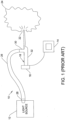
- an endoscopic system 10 for providing illumination can include a solid-state light source 12, a video monitor 14, a camera 16, and endoscope 18.
- the light source 12 generates white light that is conveyed to a distal end 22 of the endoscope 18 via a light guide 26.
- the light guide 26 includes multiple fibers and is connected between an output connector 28 of the light source 12 and a light post 30 of the endoscope 18.
- the white light illuminates a working area 24 at the distal end 22 of the endoscope.
- the video camera 16, connected to a handle 32 of the endoscope generates video signals representative of images at the working area 24 for display on video monitor 14.
- Figure 2 shows a schematic of a specific light source 12 for the known arrangement of Figure 1 .
- the light source 12 of Figure 2 includes an optical system 34 and a lens array 36 used to collimate light from a corresponding LED array 38.
- a focusing lens 40 then focuses the light onto a light guide 52.
- LED array 38 is arranged in a circular-shaped 2-dimensional array.
- Corresponding lens array 36 is located in front of the LED array 38 so that each semi-conductor light source 42 is positioned along an optical axis 44 of the corresponding lens 46.
- Lenses 46 collimate light emitted by their corresponding LEDs 42.
- Lenses 46 may represent single lenses, such as single or double aspherics, compound lenses, radiant index type lenses or combinations of each.
- Other arrangements have lens arrays that are implemented as part of an LED array by adhesion, fusion or the like. Some arrangements have a rectangular shaped LED and lens array.
- the focal length of the lens 40, and the diameter of the lenses 46 are chosen on the order of a few millimeters.
- the actual values are selected based on the size of LED emitting surface 48 which determines the field of view of the lens 46.
- the collimated light from lens array 36 travels to the focusing lens 40.
- Focusing lens 40 projects the image of each LED light emitting surface 48 onto an entrance face 50 of the light guide 42.
- the image is magnified so that the size is approximately equal to the size of the entrance face 50 of the light guide 42.
- the light guide 42 transports the light to an endoscope.
- the light passes through the endoscope to illuminate a surgical site.
- Camera 16 provides images of the surgical site for display on video monitor 14.
- An area of concern with the above described endoscopic system and other endoscopic illuminating systems is the transfer of heat from a light source through the light guide 26 to a metal junction at the distal end of the scope.
- the temperature at the distal end of the scope can be as high as 70°C. If a surgeon removes the endoscope from within a patient and places the endoscope on their body, burning of the skin of a patient may occur. Further, when the endoscope is disposed inside the body of a user, there is a possibility that the metal distal tip will injure tissue of the patient.
- One object of the invention is to provide an apparatus having a plurality of solid state light sources that are operated at a minimal voltage or power level while providing a necessary amount of light.
- One embodiment of the invention is to sense the color of light applied through an endoscope to the surgical site. Depending on the sensed color values, the power to individual light emitting diodes or diode arrays is controlled to balance the colors of light to result in a white light. In this way, white balance in a camera receiving reflected light from the light source is not as necessary as compared to light sources having no color balance feedback.
- Another embodiment of the invention automatically stops providing power to the light source when the distal end of the fiber optic cable is disconnected from the endoscope.
- Figure 3 is a block diagram of a light source 60 including a power supply unit 62 that provides a plurality of power outputs 64a, 64b, 64c to solid state light emitting devices, such as light emitting diodes 66a, 66b, 66c.
- the light emitting diodes 66a-66c provide light to light optics 68 which will be described in more detail below.
- Light optics 68 provide a collimated light output 70 to and within a hollow light transmitting rod 72.
- the light output 70 is intended to be white light.
- a fiber optic 74 is oriented to receive a miniscule portion of the light output 70.
- the fiber optic 74 provides the light received therein to a color sensor 76 disposed in the light source housing.
- the color sensor 76 provides a color output signal 78 to a color balance circuit 80.
- the color balance circuit provides color balance output signals 82a, 82b, 82c to the power supply unit 62.
- the power supply unit 62 includes individual power output circuits 63a-63c that supply power to LEDs or LED arrays 66a-66c.
- the light source embodiment illustrated in Figure 3 provides a light output 70 to light transmitting rod 72 that is received by a fiber optic cable that provides the light output to an endoscope.
- fiber optic 74 disposed at an edge at the distal end of the rod 72 receives a small portion of the light output 72 and provides the light to the color sensor 76.
- the color sensor 76 senses the properties of the light and determines what, if any, colors are dominant within the light output 70. For example, if an abundance of red light is provided in the light output 70, the condition will change the complexion or color of an image of an object on which the light output is reflected. Thus, color sensor 76 receives light from fiber optic 74 and determines the intensity of color in the fiber optic 74. Then, color sensor 76 provides color output signals 78 corresponding to combined light from the LEDs or solid state light emitting elements 66.
- Color balance circuit 80 receives the color output signals 78 from the color sensor 76 and determines which, if any, of the colored light emitting diodes 66a-66c needs to output more or less light to the fiber optics 68. The color balance circuit 80 then provides color balance output signals 82a, 82b, 82c to the power supply unit 62. Power output circuits 63a-63c individually control the light emitting diodes 66a-66c based on the color balance output signals 82 to obtain, in accordance with one embodiment, a balanced white light output 70. However, in some situations, a white light output may not be the most ideal light color for viewing an operating field. Thus, the color balance circuit 80 operates to control the light emitting elements to provide the predetermined desired color.
- the light source arrangement shown in Figure 3 which is contained within a light source housing, operates to provide a predetermined color light output 70, regardless of the conditions or properties of the various individual light emitting diodes 66a-66c which provide the light that is processed and output through the light transmitting rod 72.
- Figure 4 illustrates one embodiment of the light optics 68 provided within light source 60.
- the Figure 4 embodiment includes red, green and blue LEDs 66a-66c, respectively.
- the light optics 68 include a plurality of walls for containing light provided by the respective LEDs 66a-66c.
- the light optics 68 include a reflector or mirror 88 disposed below the green LED 66b for reflecting green light.
- the reflector 88 is oriented at approximately a 45 degree angle to reflect the green light in a substantially transverse horizontal direction as illustrated in Figure 4 .
- the green light is reflected toward a first dichroic band pass filter 90 that allows green light to pass therethrough.
- red LED 66a provides red light that is directed downwardly and passes through a second angled highpass dichroic filter 92.
- the dichroic filters 90 and 92 are glass filters with dichroic coatings. After passing through the dichroic filter 92, the red light advances to the first band pass filter 90 and is reflected transversely therefrom and substantially into alignment with the green light passing through the filter 90. Thus, the red light and the green light travel along the same optical path.
- Blue LED 66c provides light along a path transverse to the direction of light from red LED 66a.
- the blue light reflects downwardly from a surface the high-pass dichroic filter 92 in the same direction and along the same path as the red light.
- the blue light then reflects, along with the red light, from the surface of the band pass dichroic filter 90 transversely, and in substantially the same direction as the green light.
- the combined red, blue and green light passes through a focusing lens 94 that narrows the optic path of the combined light and then passes through a collimating lens 96 for entry into the light transmitting rod 72.
- the light transmitting rod 72 can be a glass rod that is adapted for connection to a proximal end 98 of a fiber optic cable 100.
- the light optics 68 combine a plurality of colors to obtain a white light output 70 for transfer to a fiber optic cable 100.
- the fiber optic cable 100 includes a plurality of optical fibers extending along the length thereof.
- Figure 5 is another embodiment of the light optics 68 that differs from the embodiment shown in Figure 4 .
- the LEDs 66a-66c are all positioned transverse to an optical output path of the light optics 68.
- Red LED 66a provides light that is reflected transversely by an angled reflector or mirror 88. The red light travels along an optical path and passes through an angled high-pass filter 104. Green LED 66b provides light in a parallel downward path that is reflected transversely by the high-pass dichroic filter 104.
- the dichroic filter 104 is oriented at approximately a 45° angle so that the red and green light combine and travel along essentially the same optical path.
- the blue LED 66c also outputs light in a downward direction that is reflected transversely by an angled highpass dichroic filter 106.
- the dichroic filter 106 allows the red and green light to pass therethrough along the same optical path as the blue light.
- the red, blue and green light are combined along a single optical path and travel to a focusing lens 94.
- the focusing lens 94 focuses the combined light and directs the light to a collimating lens 96.
- the collimating lens 96 orients the light in a straight direction for entry into the receiving rod 72.
- the receiving rod 72 transfers light to the proximal end 98 of a fiber optic cable 100.
- the proximal end 98 of the fiber optic cable 100 inserts into a light source housing that contains the light transmitting rod 72.
- the rod 72 is oriented so that the distal end thereof opens through a housing wall to receive the proximal end 98 of the fiber optic cable 100.
- the block diagram of Figure 6 shows another embodiment of the invention wherein the light source 60 is controlled by feedback signals from a camera 110.
- the proximal end 98 of the fiber optic cable 100 connects to the light source 60 as discussed above, and a distal end of the fiber optic cable connects to a light receiving port of an endoscope 112.
- the endoscope has an optical path therein to project the white light output received at the port outwardly from a distal end 114 thereof.
- a reflected image is then provided to an image sensor 116 of the camera 110 disposed at a proximal end of the endoscope 112.
- the camera 110 outputs one or both of a color balance signal 118 and a shutter speed signal 120.
- the color signal 118 and the shutter speed signal 120 are provided as control signals to the light source 60.
- an image received by the camera 110 is also provided as an image output 122 and displayed on a video monitor 124.
- the block diagram of camera 110 illustrated in Figure 7 is provided for the purpose of showing processing details for providing the signals 118, 120 to the light source 60.
- the diagram is not intended to represent a detailed operation of the camera 110 or structural elements of the camera.
- various units 122, 130, 134, 140 shown in the block diagram of Figure 7 may be provided as operations conducted by a single processor.
- the camera 110 is intended to be a high definition digital camera having, for example, a 60 frames per second imaging rate, and having the capability of adjusting the shutter speed for the respective frames.
- the image sensor 116 shown in Figure 7 senses an image from a surgical site and provides a sensed image signal 128 to the processing units 130, 132, 134 of the camera 110.
- Color sensing element 130 receives the image signal 128 and determines the white balance of the image and what, if any, colors are detracting from the desired predetermined color light output, which typically is white light. The color sensing element 130 then outputs a color balance signal 118 containing the measured color information.
- Image processing unit 132 also receives the image signal 128 and provides an image output 122 to the video monitor 124 for display thereon in a standard manner.
- Light intensity sensing unit 134 also receives the image signal 128.
- the light intensity sensing unit 134 determines the brightness of the image and thus the required shutter speed for the image sensor 116.
- the light intensity sensing unit 134 provides an intensity feedback signal 136 to a shutter pulse width generator 140.
- the shutter pulse width generator 140 provides a shutter speed signal 120 to the image sensor 116 to control the shutter speed thereof.
- the shutter speed is increased in time (length of time open) when more light needs to be sensed and the shutter speed is decreased in time when a bright light image is input to the image sensor 116.
- This brightness control operation is generally provided in digital video cameras.
- Light source 60 illustrated in the block diagram of Figure 8 cooperates with the input signals 118, 120 received from the camera 110 (illustrated in Figure 7 ) as follows.
- Color balance signal 118 from the camera 110 is received by a color balance circuit 148 of the light source 60.
- Shutter speed signal 120 from the camera is received by a pulse width generator 150 of the light source 60.
- the pulse width generator 150 of the light source 60 provides output signals 151 to a light source power unit 152.
- the light source power unit 152 also receives a plurality of color balance outputs 156a-156c from the color balance circuit 148.
- the light source power unit 152 includes individual power supply output circuits 160a, 160b, 160c that receive the respective color balance outputs 156a-156c and includes the pulse width generator output 151 from the pulse width generator 150.
- the power supply output circuits 160a-160c connect to respective LEDs 66a-66c, which provide light to the light optics 68 in a manner described above with respect to Figures 3-5 . As shown in Figure 3 , the light optics provide a light output 70 to a fiber optic cable 100.
- the camera 110 determines a color balance signal 118 and determines a shutter speed signal 120.
- the signals 118, 120 are provided to the light source 60.
- the color balance signal 118 is processed by the color balance circuit 148 to provide color balance outputs 156a-156c to the power supply circuits 160a-160c resulting in a predetermined color light output.
- the color adjustment accounts for any needed changes in intensity of the individual colors of light provided by LEDs 66a-66c.
- the light output 70 of the light optics 68 illustrated in Figure 8 is modulated in accordance with the shutter speed of the image sensor 116 of the camera.
- the LEDs 66a-66c are modulated to periodically provide the light output 70.
- the shutter speed signal 120 is received by pulse width generator 150 of the light source 60.
- the pulse width generator 150 provides pulses 151 having a width to control the amount of time the LEDs 66a-66c output light during each frame of image sensor operation of the camera 110.
- the feedback arrangement is balanced so that the light output 70 of the light source enables the image sensor 116 to operate at a predetermined shutter speed or within a predetermined desired range of shutter speeds.
- the LEDs 66a- 66c must pulse in synchronism with the camera shutter speed to provide adequate light output 70 while using less power.
- the predetermined range of shutter speeds are chosen to minimize the intensity or the time period of the light output 70 from the light source 60. Minimizing the length of time for light output 70, while maintaining a desired image output 122 for the camera 110, reduces heat generated at the distal end 114 of the endoscope 112 by the passage of light from the light source 60 therethrough. Further, minimizing the intensity of the light output 70 also reduces the amount of heat generated by the light at the distal end 114 of the endoscope 112. Therefore, in this arrangement with feedback control, the image sensor 116 preferably operates at the fastest acceptable shutter speed in order to reduce the intensity and/or modulation period of light provided to the image sensor 116.
- only the shutter speed signal 120 having a predetermined pulse width is provided to the light source 60 to modulate the light output 70.
- only the color balance signal 118 is provided to the light source 60 for controlling the light output from each of the LEDs 66a-66c.
- the light intensity feedback signal 136 is provided to the light source 60 to control only the intensity of light emitted therefrom.
- the system compensates for the target distance of an organ or tissue from the image sensor 116 at the surgical site. For example, the greater the distance of the target from the image sensor 116, the greater the intensity for the light output 70 to provide for optimal viewing.
- each of the LEDs may be defined by an array of LEDs or other solid-state devices.
- cyan, magenta and amber LEDs may include cyan, magenta and amber LEDs. Further, any combination of one or more of red, green, blue, cyan, magenta and amber LEDs is contemplated. In some embodiments, the light output may be generated by white LEDs or a combination of white and red LEDs. Finally, in yet another embodiment, a white light output 70 is generated by blue LEDs coated with yellow phosphorous.
- the light transmitting rod 72 of the light source 60 has a rectangular shape for coupling to a proximal end 98 of the fiber optic cable 100, which also has a rectangular shape. This arrangement provides a more efficient light transmission path between the light transmitting rod 72, and the fiber optic cable 100, since the LED geometry of the light source 60 is rectangular.
- the Figure 9 embodiment of the invention includes an arrangement to detect when the distal end of the fiber optic cable 100 is detached from the port of the endoscope 112.
- the light source 60 automatically shuts down to minimize the amount of light and heat energy output by the light source 60, and thus the amount of light/heat provided along the fiber 12 optic cable 100 and through the endoscope 112 to the distal end 114 thereof.
- the distal end 114 of the endoscope 112 may have a metal structure or elements that can become overheated.
- the light source 60 illustrated in Figure 9 includes a fiber optic cable disconnection detecting unit 170 for determining when the distal end of the fiber optic cable 100 is detached from the endoscope 112.
- the cable disconnection detecting unit 170 includes a laser output diode 174 and a photodiode sensor 176.
- a laser driver and timing circuit 178 periodically provides a laser diode drive output 180 to the laser diode 174.
- the laser pulse is reflected by dichroic filter 179 and passes through the focusing lens 94 and the collimating lens 96 to the fiber optic cable 100.
- the laser light passes along the fiber optic cable 100 to the distal end thereof. If the distal end of the fiber optic cable 100 is not connected to the endoscope 112, the laser pulse reflects at the open distal end and travels back through the fiber optic cable 100, the lenses 94, 96 and reflects off the dichroic filter 179.
- the laser pulse is then detected by the photodiode sensor 176, which provides a laser pulse reflection signal 182 to the laser driver and timing circuit 178.
- the laser driver and timing circuit 178 determines the length of time for the laser pulse to return to the detecting unit 170 and then provides a timing output value 186 to controller 188.
- the controller 188 is programmed with the physical length of the fiber optic cable 100 and compares the length of time of the timing output value 186 with a time value range corresponding to the known length for the fiber optic cable 100. If the time length signal values are within the predetermined range for the expected reflection time, the controller 188 outputs a disconnect or power shutdown signal 190 to the power supply 62, which turns off the power supply so that no power output 64 is provided.to the LEDs 66. Therefore, upon disconnection of the fiber optic cable 100 from the endoscope 112, light and heat no longer are output by the light source 60 or transmitted to the endoscope.
Landscapes
- Life Sciences & Earth Sciences (AREA)
- Health & Medical Sciences (AREA)
- Physics & Mathematics (AREA)
- Surgery (AREA)
- Optics & Photonics (AREA)
- Engineering & Computer Science (AREA)
- Biomedical Technology (AREA)
- Veterinary Medicine (AREA)
- Nuclear Medicine, Radiotherapy & Molecular Imaging (AREA)
- Pathology (AREA)
- Radiology & Medical Imaging (AREA)
- Biophysics (AREA)
- Public Health (AREA)
- Heart & Thoracic Surgery (AREA)
- Medical Informatics (AREA)
- Molecular Biology (AREA)
- Animal Behavior & Ethology (AREA)
- General Health & Medical Sciences (AREA)
- General Physics & Mathematics (AREA)
- Signal Processing (AREA)
- Microelectronics & Electronic Packaging (AREA)
- Spectroscopy & Molecular Physics (AREA)
- Endoscopes (AREA)
- Instruments For Viewing The Inside Of Hollow Bodies (AREA)
Applications Claiming Priority (4)
| Application Number | Priority Date | Filing Date | Title |
|---|---|---|---|
| US19959708P | 2008-11-18 | 2008-11-18 | |
| EP19179470.0A EP3610778B1 (de) | 2008-11-18 | 2009-11-17 | Endoskopische led-lichtquelle mit einem rückkopplungssteuerungssystem |
| EP09756365.4A EP2365773B1 (de) | 2008-11-18 | 2009-11-17 | Endoskop-led-lichtquelle mit einem rückkopplungssteuerungssystem |
| PCT/US2009/006155 WO2010059197A2 (en) | 2008-11-18 | 2009-11-17 | Endoscopic led light source having a feedback control system |
Related Parent Applications (2)
| Application Number | Title | Priority Date | Filing Date |
|---|---|---|---|
| EP09756365.4A Division EP2365773B1 (de) | 2008-11-18 | 2009-11-17 | Endoskop-led-lichtquelle mit einem rückkopplungssteuerungssystem |
| EP19179470.0A Division EP3610778B1 (de) | 2008-11-18 | 2009-11-17 | Endoskopische led-lichtquelle mit einem rückkopplungssteuerungssystem |
Publications (2)
| Publication Number | Publication Date |
|---|---|
| EP4233685A2 true EP4233685A2 (de) | 2023-08-30 |
| EP4233685A3 EP4233685A3 (de) | 2023-10-11 |
Family
ID=41718809
Family Applications (3)
| Application Number | Title | Priority Date | Filing Date |
|---|---|---|---|
| EP23179929.7A Pending EP4233685A3 (de) | 2008-11-18 | 2009-11-17 | Endoskopische led-lichtquelle mit einem rückkopplungssteuerungssystem |
| EP19179470.0A Active EP3610778B1 (de) | 2008-11-18 | 2009-11-17 | Endoskopische led-lichtquelle mit einem rückkopplungssteuerungssystem |
| EP09756365.4A Active EP2365773B1 (de) | 2008-11-18 | 2009-11-17 | Endoskop-led-lichtquelle mit einem rückkopplungssteuerungssystem |
Family Applications After (2)
| Application Number | Title | Priority Date | Filing Date |
|---|---|---|---|
| EP19179470.0A Active EP3610778B1 (de) | 2008-11-18 | 2009-11-17 | Endoskopische led-lichtquelle mit einem rückkopplungssteuerungssystem |
| EP09756365.4A Active EP2365773B1 (de) | 2008-11-18 | 2009-11-17 | Endoskop-led-lichtquelle mit einem rückkopplungssteuerungssystem |
Country Status (9)
| Country | Link |
|---|---|
| US (5) | US9459415B2 (de) |
| EP (3) | EP4233685A3 (de) |
| JP (1) | JP5909091B2 (de) |
| KR (1) | KR101648598B1 (de) |
| CN (1) | CN102215736B (de) |
| AU (1) | AU2009318141B2 (de) |
| CA (1) | CA2741734C (de) |
| ES (1) | ES2744458T3 (de) |
| WO (1) | WO2010059197A2 (de) |
Families Citing this family (84)
| Publication number | Priority date | Publication date | Assignee | Title |
|---|---|---|---|---|
| US20040199052A1 (en) | 2003-04-01 | 2004-10-07 | Scimed Life Systems, Inc. | Endoscopic imaging system |
| CA2741734C (en) | 2008-11-18 | 2017-07-18 | Stryker Corporation | Endoscopic led light source having a feedback control system |
| US8648932B2 (en) | 2009-08-13 | 2014-02-11 | Olive Medical Corporation | System, apparatus and methods for providing a single use imaging device for sterile environments |
| JP6165624B2 (ja) | 2010-03-25 | 2017-07-19 | デピュー シンセス プロダクツ, インコーポレーテッドDePuy Synthes Products, Inc. | 医療用使い捨て画像装置を提供するためのシステムおよび方法 |
| JP2011224042A (ja) * | 2010-04-15 | 2011-11-10 | Fujifilm Corp | 光源装置及びこれを用いた内視鏡装置 |
| US9277855B2 (en) | 2010-08-10 | 2016-03-08 | Boston Scientific Scimed, Inc. | Endoscopic system for enhanced visualization |
| JP5547118B2 (ja) * | 2011-03-03 | 2014-07-09 | 富士フイルム株式会社 | 画像取得装置および画像取得装置の作動方法 |
| EP2708021B1 (de) | 2011-05-12 | 2019-07-10 | DePuy Synthes Products, Inc. | Bildsensor mit toleranzoptimierenden verbindungen |
| CN102499615A (zh) * | 2011-09-26 | 2012-06-20 | 首都医科大学 | 照明光源装置以及取样和控制方法 |
| TW201322045A (zh) * | 2011-11-16 | 2013-06-01 | 原相科技股份有限公司 | 生理反饋控制系統及方法 |
| EP2849627B1 (de) * | 2012-05-19 | 2020-07-08 | Capso Vision, Inc. | Drahtlose optische andockvorrichtung für eine kapselkamera |
| BR112015001369A2 (pt) | 2012-07-26 | 2017-07-04 | Olive Medical Corp | sistema de câmera com sensor de imagem cmos monolítico de área mínima |
| MX346174B (es) | 2012-07-26 | 2017-03-10 | Depuy Synthes Products Inc | Esquema de iluminacion pulsada ycbcr en un entorno deficiente de luz. |
| AU2013295553B2 (en) | 2012-07-26 | 2017-10-19 | DePuy Synthes Products, Inc. | Continuous video in a light deficient environment |
| WO2014134314A1 (en) * | 2013-03-01 | 2014-09-04 | The Johns Hopkins University | Light sources, medical devices, and methods of illuminating an object of interest |
| US11013398B2 (en) * | 2013-03-13 | 2021-05-25 | Stryker Corporation | System for obtaining clear endoscope images |
| JP6404318B2 (ja) * | 2013-03-15 | 2018-10-10 | デピュイ・シンセス・プロダクツ・インコーポレイテッド | レーザーパルスの積算光エネルギー制御 |
| EP2968973B1 (de) | 2013-03-15 | 2019-12-11 | Liolios, Thomas | Für das auge ungefährliche laserstrahlung in der augenchirurgie |
| CA2906821A1 (en) * | 2013-03-15 | 2014-09-18 | Olive Medical Corporation | Scope sensing in a light controlled environment |
| EP2967285B1 (de) | 2013-03-15 | 2023-08-16 | DePuy Synthes Products, Inc. | Bildsensorsynchronisierung ohne eingangstakt und datenübertragungstakt |
| JP2016519591A (ja) | 2013-03-15 | 2016-07-07 | オリーブ・メディカル・コーポレイションOlive Medical Corporation | パルスカラー撮像システムにおける超解像度及び色運動アーチファクト補正 |
| CN105228503B (zh) | 2013-03-15 | 2017-11-07 | 德普伊新特斯产品公司 | 最小化内窥镜应用中图像传感器输入/输出和导体的数量 |
| EP2967299B1 (de) * | 2013-03-15 | 2022-11-30 | Stryker Corporation | Endoskopische lichtquelle und bildgebungssystem |
| US9692954B2 (en) | 2013-03-28 | 2017-06-27 | General Electric Company | Methods and devices for adjusting brightness of a light source |
| US10788678B2 (en) | 2013-05-17 | 2020-09-29 | Excelitas Canada, Inc. | High brightness solid state illumination system for fluorescence imaging and analysis |
| US9140839B2 (en) | 2013-07-15 | 2015-09-22 | Industrial Technology Research Institute | Lighting module and optical fiber lighting device using the same |
| JP6053079B2 (ja) * | 2013-07-31 | 2016-12-27 | 富士フイルム株式会社 | 内視鏡用光源装置、およびこれを用いた内視鏡システム |
| DK3228254T3 (da) | 2014-02-21 | 2020-03-23 | 3Dintegrated Aps | Sæt omfattende et kirurgisk instrument |
| KR102521043B1 (ko) * | 2014-03-17 | 2023-04-14 | 인튜어티브 서지컬 오퍼레이션즈 인코포레이티드 | 비백색광 일반 조명기를 포함하는 수술 시스템 |
| AU2015230978B2 (en) | 2014-03-21 | 2020-01-23 | DePuy Synthes Products, Inc. | Card edge connector for an imaging sensor |
| SG11201703716QA (en) * | 2014-11-07 | 2017-06-29 | Uvlrx Therapeutics Inc | High efficiency optical combiner for multiple non-coherent light sources |
| JP6695881B2 (ja) | 2014-12-29 | 2020-05-20 | ボストン サイエンティフィック サイムド,インコーポレイテッドBoston Scientific Scimed,Inc. | 医療装置アセンブリおよび関連する方法 |
| JP6892087B2 (ja) * | 2015-06-12 | 2021-06-18 | ソニー・オリンパスメディカルソリューションズ株式会社 | 医療用画像取得システムおよび医療用撮像装置 |
| JP6776327B2 (ja) | 2015-07-21 | 2020-10-28 | スリーディインテグレイテッド アーペーエス3Dintegrated Aps | カニューレアセンブリキット、套管針アセンブリキット、スリーブアセンブリ、低侵襲性手術システム及び方法 |
| US11020144B2 (en) | 2015-07-21 | 2021-06-01 | 3Dintegrated Aps | Minimally invasive surgery system |
| US10488018B2 (en) | 2015-08-17 | 2019-11-26 | Infinite Arthroscopy, Inc. Limited | Light source |
| DK178899B1 (en) | 2015-10-09 | 2017-05-08 | 3Dintegrated Aps | A depiction system |
| US10806536B2 (en) | 2015-11-03 | 2020-10-20 | Eos Holdings, Llc | Physician-safe illumination in ophthalmic surgeries |
| US11330963B2 (en) | 2015-11-16 | 2022-05-17 | Lazurite Holdings Llc | Wireless medical imaging system |
| JP2017104354A (ja) * | 2015-12-10 | 2017-06-15 | Hoya株式会社 | 照射システム |
| JP6203467B1 (ja) | 2015-12-14 | 2017-09-27 | オリンパス株式会社 | 光源装置 |
| WO2017175391A1 (ja) * | 2016-04-08 | 2017-10-12 | オリンパス株式会社 | 照明装置およびこれを備えた内視鏡 |
| US10690904B2 (en) | 2016-04-12 | 2020-06-23 | Stryker Corporation | Multiple imaging modality light source |
| US20170366773A1 (en) * | 2016-06-21 | 2017-12-21 | Siemens Aktiengesellschaft | Projection in endoscopic medical imaging |
| US10835102B2 (en) * | 2016-07-28 | 2020-11-17 | Verily Life Sciences Llc | Tunable color-temperature white light source |
| JP6878574B2 (ja) | 2016-09-09 | 2021-05-26 | エンテラス メディカル インコーポレイテッドEntellus Medical,Inc. | 無線内視鏡 |
| BR112019013145A2 (pt) * | 2016-12-27 | 2020-01-07 | DePuy Synthes Products, Inc. | Sistemas, métodos e dispositivos para fornecer iluminação em um ambiente de imageamento endoscópico |
| MX2019009715A (es) * | 2017-02-15 | 2020-01-27 | Infinite Arthroscopy Inc Ltd | Sistema medico inalambrico de formacion de imagen que comprende unidad de cabezal y cable de luz que comprende fuente luminosa integrada. |
| CN111031882B (zh) * | 2017-08-04 | 2023-06-30 | 波士顿科学医学有限公司 | 具有光源和光转换机构的照明设备 |
| WO2019088938A1 (en) | 2017-10-31 | 2019-05-09 | Benlioglu Muesfik | Led light source device for photodynamic therapy |
| WO2019130753A1 (ja) * | 2017-12-27 | 2019-07-04 | オリンパス株式会社 | 光源装置 |
| EP3737276A4 (de) * | 2018-01-10 | 2021-10-20 | ChemImage Corporation | Zeitkorrelierte quellenmodulation für endoskopie |
| CN108371535A (zh) * | 2018-01-26 | 2018-08-07 | 重庆金山医疗器械有限公司 | 内窥镜多色照明系统 |
| JP7105300B2 (ja) * | 2018-04-24 | 2022-07-22 | オリンパス株式会社 | 内視鏡システム及び内視鏡システムの作動方法 |
| EP3857866A1 (de) * | 2018-09-27 | 2021-08-04 | Intuitive Surgical Operations, Inc. | Geschlossener regelkreis zur beleuchtung in einem endoskopischen kamerasystem |
| US11633083B2 (en) * | 2018-12-20 | 2023-04-25 | Acclarent, Inc. | 3D scanning of nasal tract with deflectable endoscope |
| CN109507794A (zh) * | 2018-12-27 | 2019-03-22 | 深圳开立生物医疗科技股份有限公司 | 一种内窥镜系统及其光源装置 |
| EP3911221A1 (de) | 2019-01-17 | 2021-11-24 | Stryker Corporation | Systeme und verfahren zur medizinischen bildgebung unter verwendung eines rolling-shutter-bildgebers |
| DE102019102361B4 (de) | 2019-01-30 | 2020-09-10 | T.Q. Optoelectronics Co., Ltd. | Lichtquellenmodul eines endoskops |
| JP7374598B2 (ja) * | 2019-03-15 | 2023-11-07 | ソニー・オリンパスメディカルソリューションズ株式会社 | 光源装置、医療用観察システム、照明方法およびプログラム |
| US10742858B1 (en) | 2019-03-28 | 2020-08-11 | Karl Storz Imaging, Inc. | System and method for prioritizing the synchronization of a light source with image sensor |
| US10680141B1 (en) * | 2019-06-04 | 2020-06-09 | Dell Products L.P. | Light-emitting diode (LED) switching system |
| CN112097910A (zh) * | 2019-06-17 | 2020-12-18 | 广州市合熠电子科技有限公司 | 一种智能型rgb数字颜色传感器电路系统 |
| JP7714518B2 (ja) * | 2019-07-08 | 2025-07-29 | ストライカー コーポレイション | 目標スペクトル照明のためのシステムおよび方法 |
| CN110740307A (zh) * | 2019-11-18 | 2020-01-31 | 重庆金山医疗技术研究院有限公司 | 自动白平衡的内窥镜及白平衡参数调节方法 |
| JP7528226B2 (ja) * | 2020-01-13 | 2024-08-05 | ハーグ-シュトライト アクチェンゲゼルシャフト | 同期した光源及びカメラを有する眼科顕微鏡 |
| WO2021166090A1 (ja) * | 2020-02-18 | 2021-08-26 | オリンパス株式会社 | 内視鏡用光源装置 |
| USD938584S1 (en) | 2020-03-30 | 2021-12-14 | Lazurite Holdings Llc | Hand piece |
| KR20210122472A (ko) | 2020-04-01 | 2021-10-12 | 한국전기연구원 | 내시경 영상 품질 개선 방법, 장치 및 시스템 |
| USD972176S1 (en) | 2020-08-06 | 2022-12-06 | Lazurite Holdings Llc | Light source |
| EP4272427A1 (de) | 2020-12-30 | 2023-11-08 | Stryker Corporation | Systeme und verfahren zur abschwächung von artefakten in der medizinischen bildgebung |
| EP4274464A1 (de) * | 2021-01-06 | 2023-11-15 | Intuitive Surgical Operations, Inc. | Vorrichtungen und verfahren zur erzeugung einer gleichmässigen beleuchtung |
| US20220226569A1 (en) * | 2021-01-19 | 2022-07-21 | Chs Healthcare Ventures, Inc. | Method and Manufacture of a dual lumen fiber optic medical infusion line |
| US12232707B2 (en) | 2021-01-26 | 2025-02-25 | Arthrex, Inc. | Endoscope thermal reflector |
| CN113049106B (zh) * | 2021-03-11 | 2021-12-21 | 广州市合熠智能科技股份有限公司 | 一种数字智能型颜色传感器系统 |
| CN115119356B (zh) * | 2021-03-17 | 2025-04-25 | 松下电气机器(北京)有限公司 | 光源动态同步方法及led灯具系统 |
| CN117356171A (zh) | 2021-07-20 | 2024-01-05 | 爱尔康公司 | 光引擎校准系统和方法 |
| US12396618B2 (en) * | 2021-11-09 | 2025-08-26 | Karl Storz Imaging, Inc. | Dynamic light source status indication for endoscopic systems |
| US12239409B2 (en) | 2022-02-28 | 2025-03-04 | Visionsense Ltd. | Fluorescence imaging camera assembly for open surgery |
| CN117377173A (zh) * | 2022-06-30 | 2024-01-09 | 深圳开立生物医疗科技股份有限公司 | 一种照明校正方法、装置、电子设备及存储介质 |
| US20240024867A1 (en) * | 2022-07-22 | 2024-01-25 | Beckman Coulter, Inc. | Flowcell holder and biological analysis systems and methods |
| WO2024128822A1 (ko) * | 2022-12-14 | 2024-06-20 | 삼성전자 주식회사 | 생체 정보를 측정하기 위한 전자 장치 및 그 전자 장치에서의 동작 방법 |
| US11744452B1 (en) * | 2023-04-05 | 2023-09-05 | Apollo Innovations, Llc | Intra-oral scanning and image acquisition module |
| US20250098951A1 (en) * | 2023-09-27 | 2025-03-27 | Olympus Corporation | Light source device for endoscope |
Citations (2)
| Publication number | Priority date | Publication date | Assignee | Title |
|---|---|---|---|---|
| US6921920B2 (en) | 2001-08-31 | 2005-07-26 | Smith & Nephew, Inc. | Solid-state light source |
| JP4590647B2 (ja) * | 1999-07-30 | 2010-12-01 | 日東光学株式会社 | 光源装置およびプロジェクタ装置 |
Family Cites Families (106)
| Publication number | Priority date | Publication date | Assignee | Title |
|---|---|---|---|---|
| JPS5410237Y2 (de) | 1973-09-29 | 1979-05-11 | ||
| US4538062A (en) * | 1981-11-19 | 1985-08-27 | Olympus Optical Co., Ltd. | Focusing detecting device with coaxial source and detector |
| JPS5887526A (ja) * | 1981-11-20 | 1983-05-25 | Olympus Optical Co Ltd | 内視鏡光源装置 |
| US5084612A (en) * | 1989-10-20 | 1992-01-28 | Fuji Photo Film Co., Ltd. | Imaging method for scanning microscopes, and confocal scanning microscope |
| JP3004293B2 (ja) * | 1989-11-22 | 2000-01-31 | オリンパス光学工業株式会社 | 内視鏡用光源装置 |
| JP2613118B2 (ja) * | 1990-04-10 | 1997-05-21 | 富士写真フイルム株式会社 | 共焦点走査型顕微鏡 |
| US5093769A (en) | 1990-10-04 | 1992-03-03 | Luntsford K Paul | Surgical lighting system |
| JP3012341B2 (ja) * | 1990-12-25 | 2000-02-21 | オリンパス光学工業株式会社 | 内視鏡装置 |
| US5716324A (en) * | 1992-08-25 | 1998-02-10 | Fuji Photo Film Co., Ltd. | Endoscope with surface and deep portion imaging systems |
| JPH0767832A (ja) | 1993-09-03 | 1995-03-14 | Toshiba Corp | 内視鏡装置の光源ユニット |
| US5717605A (en) * | 1993-10-14 | 1998-02-10 | Olympus Optical Co., Ltd. | Color classification apparatus |
| JPH07275192A (ja) * | 1994-04-14 | 1995-10-24 | Toshiba Corp | 内視鏡装置 |
| JP3555230B2 (ja) | 1994-05-18 | 2004-08-18 | 株式会社ニコン | 投影露光装置 |
| US5636259A (en) | 1995-05-18 | 1997-06-03 | Continental X-Ray Corporation | Universal radiographic/fluoroscopic digital room |
| US5842765A (en) * | 1995-07-24 | 1998-12-01 | General Electric Company | Tricolor lighting system |
| CA2253820C (en) * | 1996-05-06 | 2007-10-23 | Cimatrix | Smart progressive-scan charge-coupled device camera |
| US5917882A (en) | 1996-11-29 | 1999-06-29 | Continental X-Ray Corporation | Radiographic/fluoroscopic imaging system with reduced patient dose and faster transitions between radiographic and fluoroscopic modes |
| JPH10192232A (ja) * | 1997-01-14 | 1998-07-28 | Olympus Optical Co Ltd | 内視鏡装置 |
| US6167173A (en) * | 1997-01-27 | 2000-12-26 | Carl Zeiss Jena Gmbh | Laser scanning microscope |
| GB9703156D0 (en) * | 1997-02-15 | 1997-04-02 | Univ Strathclyde | Optical element |
| JPH11218690A (ja) * | 1998-02-04 | 1999-08-10 | Olympus Optical Co Ltd | 落射蛍光照明光学系を備えた顕微鏡 |
| JP4010631B2 (ja) * | 1998-03-11 | 2007-11-21 | ペンタックス株式会社 | 簡易型内視鏡装置 |
| US6485414B1 (en) * | 1998-07-13 | 2002-11-26 | Ceramoptec Industries, Inc. | Color video diagnostic system for mini-endoscopes |
| EP1099405B1 (de) * | 1999-05-18 | 2005-08-03 | Olympus Corporation | Endoskop |
| JP2001224015A (ja) | 2000-02-07 | 2001-08-17 | Olympus Optical Co Ltd | 内視鏡装置及び光源装置 |
| US20050182434A1 (en) | 2000-08-11 | 2005-08-18 | National Research Council Of Canada | Method and apparatus for performing intra-operative angiography |
| US20050099824A1 (en) * | 2000-08-04 | 2005-05-12 | Color Kinetics, Inc. | Methods and systems for medical lighting |
| US6663560B2 (en) * | 1999-12-17 | 2003-12-16 | Digital Optical Imaging Corporation | Methods and apparatus for imaging using a light guide bundle and a spatial light modulator |
| US6692430B2 (en) * | 2000-04-10 | 2004-02-17 | C2Cure Inc. | Intra vascular imaging apparatus |
| US6577453B2 (en) * | 2000-04-26 | 2003-06-10 | Fuji Photo Film Co., Ltd. | Image reading apparatus |
| JP4321697B2 (ja) * | 2000-08-02 | 2009-08-26 | 富士フイルム株式会社 | 蛍光画像表示方法および装置 |
| US6730019B2 (en) * | 2000-10-24 | 2004-05-04 | Karl Storz Gmbh & Co. Kg | Endoscope with LED illumination |
| US6826424B1 (en) * | 2000-12-19 | 2004-11-30 | Haishan Zeng | Methods and apparatus for fluorescence and reflectance imaging and spectroscopy and for contemporaneous measurements of electromagnetic radiation with multiple measuring devices |
| JP4006179B2 (ja) * | 2000-12-26 | 2007-11-14 | キヤノン株式会社 | 画像表示装置および画像表示システム |
| JP2002238845A (ja) * | 2001-02-16 | 2002-08-27 | Asahi Optical Co Ltd | 電子内視鏡用光源制御装置 |
| JP2002252413A (ja) * | 2001-02-26 | 2002-09-06 | Hitachi Ltd | 半導体レーザモジュール及びこれを用いた光システム |
| US7123756B2 (en) * | 2001-04-27 | 2006-10-17 | Fuji Photo Film Co., Ltd. | Method and apparatus for standardized fluorescence image generation |
| JP4390096B2 (ja) * | 2001-07-06 | 2009-12-24 | 富士フイルム株式会社 | 内視鏡装置 |
| US7085492B2 (en) * | 2001-08-27 | 2006-08-01 | Ibsen Photonics A/S | Wavelength division multiplexed device |
| DE10256365A1 (de) * | 2001-12-04 | 2003-07-17 | Ccs Inc | Lichtabstrahlungsvorrichtung, Lichtquellenvorrichtung, Beleuchtungseinheit und Lichtverbindungsmechanismus |
| US6924490B2 (en) * | 2002-01-10 | 2005-08-02 | Olympus Optical Co., Ltd. | Microscope system |
| JP2003269919A (ja) * | 2002-03-11 | 2003-09-25 | Mitsutoyo Corp | 画像処理型測定機の照明装置 |
| JP3778114B2 (ja) * | 2002-03-27 | 2006-05-24 | ソニー株式会社 | 露光制御方法、露光制御回路、撮像装置、プログラム、記憶媒体 |
| US7209162B2 (en) * | 2002-04-17 | 2007-04-24 | Pentax Corporation | Electronic endoscope apparatus |
| US7223986B2 (en) * | 2002-08-29 | 2007-05-29 | Olympus Optical Co., Ltd. | Laser scanning microscope |
| US6876494B2 (en) * | 2002-09-30 | 2005-04-05 | Fuji Photo Film Co., Ltd. | Imaging forming apparatus |
| DE10339495B4 (de) * | 2002-10-08 | 2007-10-04 | Xtreme Technologies Gmbh | Anordnung zur optischen Detektion eines bewegten Targetstromes für eine gepulste energiestrahlgepumpte Strahlungserzeugung |
| JP2004184437A (ja) * | 2002-11-29 | 2004-07-02 | Toshiba Corp | 半導体レーザ装置、半導体レーザの制御方法、映像表示装置 |
| US7448995B2 (en) * | 2003-06-23 | 2008-11-11 | Microvision, Inc. | Scanning endoscope |
| CN100457020C (zh) * | 2003-06-23 | 2009-02-04 | 微视公司 | 扫描内窥镜 |
| JP2005084569A (ja) * | 2003-09-11 | 2005-03-31 | Brother Ind Ltd | 画像表示装置 |
| CA2581668A1 (en) * | 2003-09-26 | 2005-04-07 | Tidal Photonics, Inc | Apparatus and methods relating to expanded dynamic range imaging endoscope systems |
| EP1713540A2 (de) * | 2003-09-26 | 2006-10-25 | Tidal Photonics, Inc. | Gerät und verfahren zur durchführung von fototherapie, fotodynamische therapie und diagnose |
| JP4062225B2 (ja) * | 2003-09-30 | 2008-03-19 | ブラザー工業株式会社 | 光スキャナおよびそれを備えた画像形成装置 |
| WO2005052668A1 (ja) * | 2003-11-26 | 2005-06-09 | Olympus Corporation | レーザ走査型蛍光顕微鏡 |
| US20050187441A1 (en) * | 2004-01-19 | 2005-08-25 | Kenji Kawasaki | Laser-scanning examination apparatus |
| JP2005345716A (ja) * | 2004-06-02 | 2005-12-15 | Olympus Corp | 顕微鏡 |
| JP3906926B2 (ja) * | 2004-02-20 | 2007-04-18 | 大日精化工業株式会社 | 光制御式光路切替型光信号伝送装置および光信号光路切替方法 |
| US7304789B2 (en) * | 2004-02-24 | 2007-12-04 | Olympus Corporation | Microscope system and objective unit |
| US7176428B2 (en) * | 2004-03-12 | 2007-02-13 | Olympus Corporation | Laser-based, multiphoton-excitation-type optical examination apparatus |
| JP3972066B2 (ja) * | 2004-03-16 | 2007-09-05 | 大日精化工業株式会社 | 光制御式光路切替型データ配信装置および配信方法 |
| US7233437B2 (en) * | 2004-03-25 | 2007-06-19 | Olympus Corporation | Laser-scanning microscope |
| DE602005007403D1 (de) * | 2004-03-25 | 2008-07-24 | Olympus Corp | Scannendes konfokales Mikroskop |
| DE102004016253B4 (de) * | 2004-04-02 | 2006-02-23 | Leica Microsystems Cms Gmbh | Rastermikroskop und Verfahren zur rastermikroskopischen Untersuchung einer Probe |
| US7268938B2 (en) * | 2004-04-07 | 2007-09-11 | Olympus Coporation | In-vivo examination apparatus |
| JP4885429B2 (ja) * | 2004-05-13 | 2012-02-29 | オリンパス株式会社 | 光刺激装置および光走査型観察装置 |
| EP1760454A4 (de) * | 2004-06-24 | 2008-09-03 | Olympus Corp | Photometrische fluoreszenzvorrichtung |
| JP4481098B2 (ja) * | 2004-07-06 | 2010-06-16 | オリンパス株式会社 | 生体観察装置 |
| JP4642401B2 (ja) * | 2004-07-26 | 2011-03-02 | オリンパス株式会社 | レーザ走査型観察装置 |
| JP4434882B2 (ja) * | 2004-08-27 | 2010-03-17 | オリンパス株式会社 | レーザ走査型蛍光観察装置 |
| JP4817632B2 (ja) * | 2004-09-27 | 2011-11-16 | 京セラ株式会社 | Ledファイバ光源装置及びそれを用いた内視鏡 |
| WO2006051811A1 (ja) * | 2004-11-10 | 2006-05-18 | Olympus Corporation | 生体観察装置 |
| JP2006139181A (ja) * | 2004-11-15 | 2006-06-01 | Olympus Corp | 顕微鏡装置 |
| JP2006208681A (ja) * | 2005-01-27 | 2006-08-10 | Olympus Corp | 接続ユニットおよび光走査型蛍光観察装置 |
| US7530948B2 (en) * | 2005-02-28 | 2009-05-12 | University Of Washington | Tethered capsule endoscope for Barrett's Esophagus screening |
| US7234820B2 (en) * | 2005-04-11 | 2007-06-26 | Philips Lumileds Lighting Company, Llc | Illuminators using reflective optics with recycling and color mixing |
| JP4845450B2 (ja) * | 2005-08-08 | 2011-12-28 | オリンパス株式会社 | 麻酔ケース |
| JP4731248B2 (ja) * | 2005-08-25 | 2011-07-20 | Hoya株式会社 | 電子内視鏡システム |
| JP2007114542A (ja) * | 2005-10-21 | 2007-05-10 | Olympus Corp | 顕微鏡観察装置および顕微鏡観察方法 |
| JP5079240B2 (ja) * | 2006-02-06 | 2012-11-21 | 株式会社ニデック | 網膜機能計測装置 |
| JP5044126B2 (ja) * | 2006-02-23 | 2012-10-10 | オリンパス株式会社 | 内視鏡観察装置および画像形成を行う内視鏡の作動方法 |
| JP4818753B2 (ja) * | 2006-02-28 | 2011-11-16 | オリンパス株式会社 | 内視鏡システム |
| JP4954573B2 (ja) * | 2006-02-28 | 2012-06-20 | オリンパス株式会社 | 内視鏡システム |
| US7583389B2 (en) * | 2006-04-07 | 2009-09-01 | Amo Wavefront Sciences, Llc | Geometric measurement system and method of measuring a geometric characteristic of an object |
| JP4864528B2 (ja) * | 2006-04-27 | 2012-02-01 | Hoya株式会社 | 内視鏡装置 |
| JP4845590B2 (ja) * | 2006-05-22 | 2011-12-28 | オリンパス株式会社 | 内視鏡システム |
| JP2008043494A (ja) * | 2006-08-14 | 2008-02-28 | Olympus Corp | 蛍光内視鏡システム、蛍光観測装置、蛍光観測方法、蛍光情報処理装置、および蛍光情報処理方法 |
| JP2008070350A (ja) * | 2006-08-15 | 2008-03-27 | Fujifilm Corp | 光断層画像化装置 |
| JP2008070349A (ja) * | 2006-08-15 | 2008-03-27 | Fujifilm Corp | 光断層画像化装置 |
| US20080058602A1 (en) * | 2006-08-30 | 2008-03-06 | Karl Storz Endovision | Endoscopic device with temperature based light source control |
| CN101295102A (zh) * | 2006-12-07 | 2008-10-29 | 罗门哈斯丹麦金融有限公司 | 使用伸长的照明装置的液晶显示器背光 |
| US7661862B2 (en) * | 2006-12-07 | 2010-02-16 | Skc Haas Display Films Co., Ltd. | LCD display backlight using elongated illuminators |
| JP5112832B2 (ja) * | 2006-12-11 | 2013-01-09 | オリンパス株式会社 | 顕微鏡対物レンズ及びそれを用いた蛍光観察装置 |
| JP4674589B2 (ja) * | 2007-02-05 | 2011-04-20 | ソニー株式会社 | 固体撮像装置および撮像装置 |
| DE102007007797B4 (de) * | 2007-02-16 | 2017-11-16 | Leica Microsystems Cms Gmbh | Fluoreszenzmikroskop mit Beleuchtungseinrichtung |
| JP2008225095A (ja) * | 2007-03-13 | 2008-09-25 | Olympus Corp | 光走査型観察装置 |
| JP2008264514A (ja) * | 2007-03-23 | 2008-11-06 | Hoya Corp | 内視鏡用光源装置 |
| US7682027B2 (en) * | 2007-04-09 | 2010-03-23 | Alcon, Inc. | Multi-LED ophthalmic illuminator |
| JP5133595B2 (ja) * | 2007-05-15 | 2013-01-30 | オリンパスメディカルシステムズ株式会社 | 照明光検出用光学系並びにそれを備えた光学装置及び内視鏡装置 |
| WO2009033021A2 (en) * | 2007-09-05 | 2009-03-12 | Chroma Technology Corporation | Light source with wavelength converting phosphor |
| JP4940070B2 (ja) * | 2007-09-10 | 2012-05-30 | 国立大学法人 東京大学 | 眼底観察装置、眼科画像処理装置及びプログラム |
| US8711473B2 (en) * | 2007-09-14 | 2014-04-29 | Olympus Corporation | Focus adjustment unit and optical scanning microscope |
| JP5529384B2 (ja) * | 2007-09-28 | 2014-06-25 | テルモ株式会社 | 光ロータリアダプタおよびこれを用いる光断層画像化装置 |
| US20090244521A1 (en) * | 2008-03-31 | 2009-10-01 | General Electric Company | System and method for multi-mode optical imaging |
| CA2741734C (en) | 2008-11-18 | 2017-07-18 | Stryker Corporation | Endoscopic led light source having a feedback control system |
| DE102011016138A1 (de) * | 2011-03-30 | 2012-10-04 | Karl Storz Gmbh & Co. Kg | Vorrichtung zur Fluoreszenzdiagnose |
-
2009
- 2009-11-17 CA CA2741734A patent/CA2741734C/en not_active Expired - Fee Related
- 2009-11-17 CN CN200980145842.3A patent/CN102215736B/zh active Active
- 2009-11-17 ES ES09756365T patent/ES2744458T3/es active Active
- 2009-11-17 AU AU2009318141A patent/AU2009318141B2/en not_active Ceased
- 2009-11-17 WO PCT/US2009/006155 patent/WO2010059197A2/en not_active Ceased
- 2009-11-17 US US12/998,375 patent/US9459415B2/en active Active
- 2009-11-17 EP EP23179929.7A patent/EP4233685A3/de active Pending
- 2009-11-17 JP JP2011536337A patent/JP5909091B2/ja active Active
- 2009-11-17 EP EP19179470.0A patent/EP3610778B1/de active Active
- 2009-11-17 KR KR1020117011196A patent/KR101648598B1/ko not_active Expired - Fee Related
- 2009-11-17 EP EP09756365.4A patent/EP2365773B1/de active Active
-
2016
- 2016-04-21 US US15/134,488 patent/US10670817B2/en active Active
-
2020
- 2020-06-01 US US16/889,751 patent/US11467358B2/en active Active
-
2022
- 2022-10-10 US US18/045,445 patent/US12019287B2/en active Active
-
2024
- 2024-06-21 US US18/751,127 patent/US20240345339A1/en active Pending
Patent Citations (2)
| Publication number | Priority date | Publication date | Assignee | Title |
|---|---|---|---|---|
| JP4590647B2 (ja) * | 1999-07-30 | 2010-12-01 | 日東光学株式会社 | 光源装置およびプロジェクタ装置 |
| US6921920B2 (en) | 2001-08-31 | 2005-07-26 | Smith & Nephew, Inc. | Solid-state light source |
Also Published As
| Publication number | Publication date |
|---|---|
| AU2009318141B2 (en) | 2014-05-22 |
| CA2741734A1 (en) | 2010-05-27 |
| CN102215736A (zh) | 2011-10-12 |
| US11467358B2 (en) | 2022-10-11 |
| ES2744458T3 (es) | 2020-02-25 |
| EP3610778A1 (de) | 2020-02-19 |
| CA2741734C (en) | 2017-07-18 |
| US10670817B2 (en) | 2020-06-02 |
| US20240345339A1 (en) | 2024-10-17 |
| US20210018703A1 (en) | 2021-01-21 |
| US9459415B2 (en) | 2016-10-04 |
| KR20110094283A (ko) | 2011-08-23 |
| EP2365773A2 (de) | 2011-09-21 |
| EP4233685A3 (de) | 2023-10-11 |
| US20230168447A1 (en) | 2023-06-01 |
| US12019287B2 (en) | 2024-06-25 |
| US20160231494A1 (en) | 2016-08-11 |
| CN102215736B (zh) | 2015-04-29 |
| WO2010059197A3 (en) | 2010-08-05 |
| EP3610778B1 (de) | 2023-07-05 |
| WO2010059197A2 (en) | 2010-05-27 |
| EP2365773B1 (de) | 2019-06-12 |
| JP5909091B2 (ja) | 2016-04-26 |
| JP2012509098A (ja) | 2012-04-19 |
| US20110208004A1 (en) | 2011-08-25 |
| KR101648598B1 (ko) | 2016-08-16 |
| AU2009318141A1 (en) | 2010-05-27 |
Similar Documents
| Publication | Publication Date | Title |
|---|---|---|
| US12019287B2 (en) | Endoscopic LED light source having a feedback control system | |
| US11575811B2 (en) | Systems, methods, and devices for providing illumination in an endoscopic imaging environment | |
| EP2967299B1 (de) | Endoskopische lichtquelle und bildgebungssystem | |
| US10524646B2 (en) | Light source apparatus | |
| CN102334972A (zh) | 内窥镜系统 | |
| EP1832225B1 (de) | Optischer Sensor und Sicherheits- und Steuerungssystem für eine endoskopische Lichtquelle mit optischem Sensor | |
| CN109310285B (zh) | 电子镜及电子内窥镜系统 | |
| US12396618B2 (en) | Dynamic light source status indication for endoscopic systems | |
| CN117562490A (zh) | 一种内窥镜照明系统、便于实现稳定照明的内窥镜及方法 | |
| JP2019030743A (ja) | 内視鏡用光源装置、内視鏡システム、及び位置調整方法 |
Legal Events
| Date | Code | Title | Description |
|---|---|---|---|
| PUAI | Public reference made under article 153(3) epc to a published international application that has entered the european phase |
Free format text: ORIGINAL CODE: 0009012 |
|
| STAA | Information on the status of an ep patent application or granted ep patent |
Free format text: STATUS: REQUEST FOR EXAMINATION WAS MADE |
|
| 17P | Request for examination filed |
Effective date: 20230619 |
|
| AC | Divisional application: reference to earlier application |
Ref document number: 2365773 Country of ref document: EP Kind code of ref document: P Ref document number: 3610778 Country of ref document: EP Kind code of ref document: P |
|
| AK | Designated contracting states |
Kind code of ref document: A2 Designated state(s): AT BE BG CH CY CZ DE DK EE ES FI FR GB GR HR HU IE IS IT LI LT LU LV MC MK MT NL NO PL PT RO SE SI SK SM TR |
|
| PUAL | Search report despatched |
Free format text: ORIGINAL CODE: 0009013 |
|
| AK | Designated contracting states |
Kind code of ref document: A3 Designated state(s): AT BE BG CH CY CZ DE DK EE ES FI FR GB GR HR HU IE IS IT LI LT LU LV MC MK MT NL NO PL PT RO SE SI SK SM TR |
|
| RIC1 | Information provided on ipc code assigned before grant |
Ipc: A61B 1/00 20060101ALI20230907BHEP Ipc: A61B 1/06 20060101AFI20230907BHEP |
|
| RAP3 | Party data changed (applicant data changed or rights of an application transferred) |
Owner name: STRYKER CORPORATION |
|
| STAA | Information on the status of an ep patent application or granted ep patent |
Free format text: STATUS: EXAMINATION IS IN PROGRESS |
|
| 17Q | First examination report despatched |
Effective date: 20250925 |