EP3943047B1 - Vorrichtung für den ersatz einer herzklappe - Google Patents
Vorrichtung für den ersatz einer herzklappe Download PDFInfo
- Publication number
- EP3943047B1 EP3943047B1 EP21181385.2A EP21181385A EP3943047B1 EP 3943047 B1 EP3943047 B1 EP 3943047B1 EP 21181385 A EP21181385 A EP 21181385A EP 3943047 B1 EP3943047 B1 EP 3943047B1
- Authority
- EP
- European Patent Office
- Prior art keywords
- valve
- retainer
- tissue
- support
- valve support
- Prior art date
- Legal status (The legal status is an assumption and is not a legal conclusion. Google has not performed a legal analysis and makes no representation as to the accuracy of the status listed.)
- Active
Links
- 210000003709 heart valve Anatomy 0.000 title claims description 119
- 210000001519 tissue Anatomy 0.000 claims description 182
- 210000004115 mitral valve Anatomy 0.000 claims description 124
- 238000011144 upstream manufacturing Methods 0.000 claims description 53
- 238000007789 sealing Methods 0.000 claims description 37
- 230000017531 blood circulation Effects 0.000 claims description 14
- 230000002861 ventricular Effects 0.000 claims description 13
- 210000005003 heart tissue Anatomy 0.000 claims description 11
- 229910001000 nickel titanium Inorganic materials 0.000 claims description 9
- HLXZNVUGXRDIFK-UHFFFAOYSA-N nickel titanium Chemical compound [Ti].[Ti].[Ti].[Ti].[Ti].[Ti].[Ti].[Ti].[Ti].[Ti].[Ti].[Ni].[Ni].[Ni].[Ni].[Ni].[Ni].[Ni].[Ni].[Ni].[Ni].[Ni].[Ni].[Ni].[Ni] HLXZNVUGXRDIFK-UHFFFAOYSA-N 0.000 claims description 7
- 239000012781 shape memory material Substances 0.000 claims description 5
- 241000283690 Bos taurus Species 0.000 claims description 3
- 210000003516 pericardium Anatomy 0.000 claims description 3
- 210000000591 tricuspid valve Anatomy 0.000 claims description 3
- 238000005516 engineering process Methods 0.000 description 107
- 210000002216 heart Anatomy 0.000 description 60
- 238000000034 method Methods 0.000 description 53
- 238000013459 approach Methods 0.000 description 48
- 210000005240 left ventricle Anatomy 0.000 description 29
- 230000001746 atrial effect Effects 0.000 description 22
- 210000005246 left atrium Anatomy 0.000 description 20
- 210000001765 aortic valve Anatomy 0.000 description 19
- 230000036961 partial effect Effects 0.000 description 14
- 210000003484 anatomy Anatomy 0.000 description 13
- 238000002513 implantation Methods 0.000 description 13
- 230000004044 response Effects 0.000 description 12
- 239000000463 material Substances 0.000 description 11
- 230000007704 transition Effects 0.000 description 11
- 239000008280 blood Substances 0.000 description 9
- 210000004369 blood Anatomy 0.000 description 9
- 230000001788 irregular Effects 0.000 description 9
- 230000005012 migration Effects 0.000 description 9
- 238000013508 migration Methods 0.000 description 9
- 230000000087 stabilizing effect Effects 0.000 description 9
- 238000004873 anchoring Methods 0.000 description 8
- 210000004971 interatrial septum Anatomy 0.000 description 8
- 230000008439 repair process Effects 0.000 description 8
- 210000005166 vasculature Anatomy 0.000 description 8
- 230000008901 benefit Effects 0.000 description 7
- 230000007246 mechanism Effects 0.000 description 7
- 208000005907 mitral valve insufficiency Diseases 0.000 description 7
- 210000003540 papillary muscle Anatomy 0.000 description 7
- MWCLLHOVUTZFKS-UHFFFAOYSA-N Methyl cyanoacrylate Chemical compound COC(=O)C(=C)C#N MWCLLHOVUTZFKS-UHFFFAOYSA-N 0.000 description 6
- 230000008878 coupling Effects 0.000 description 5
- 238000010168 coupling process Methods 0.000 description 5
- 238000005859 coupling reaction Methods 0.000 description 5
- 229910003460 diamond Inorganic materials 0.000 description 5
- 239000010432 diamond Substances 0.000 description 5
- 239000005020 polyethylene terephthalate Substances 0.000 description 5
- 101100451260 Arabidopsis thaliana HMGS gene Proteins 0.000 description 4
- 208000032750 Device leakage Diseases 0.000 description 4
- 210000003698 chordae tendineae Anatomy 0.000 description 4
- 208000008813 mosaic variegated aneuploidy syndrome Diseases 0.000 description 4
- 229920001343 polytetrafluoroethylene Polymers 0.000 description 4
- 239000004810 polytetrafluoroethylene Substances 0.000 description 4
- 239000012858 resilient material Substances 0.000 description 4
- 210000005245 right atrium Anatomy 0.000 description 4
- 208000031229 Cardiomyopathies Diseases 0.000 description 3
- 229920004934 Dacron® Polymers 0.000 description 3
- 208000012287 Prolapse Diseases 0.000 description 3
- 230000002159 abnormal effect Effects 0.000 description 3
- 210000002376 aorta thoracic Anatomy 0.000 description 3
- 238000005452 bending Methods 0.000 description 3
- 239000000560 biocompatible material Substances 0.000 description 3
- 230000000747 cardiac effect Effects 0.000 description 3
- 238000010276 construction Methods 0.000 description 3
- 238000013461 design Methods 0.000 description 3
- 239000004744 fabric Substances 0.000 description 3
- 230000006870 function Effects 0.000 description 3
- 230000003601 intercostal effect Effects 0.000 description 3
- 230000003387 muscular Effects 0.000 description 3
- 239000005022 packaging material Substances 0.000 description 3
- 230000035479 physiological effects, processes and functions Effects 0.000 description 3
- -1 polyethylene terephthalate Polymers 0.000 description 3
- 238000011084 recovery Methods 0.000 description 3
- 230000035488 systolic blood pressure Effects 0.000 description 3
- 210000001631 vena cava inferior Anatomy 0.000 description 3
- 208000003430 Mitral Valve Prolapse Diseases 0.000 description 2
- 206010067171 Regurgitation Diseases 0.000 description 2
- 238000010521 absorption reaction Methods 0.000 description 2
- 230000005540 biological transmission Effects 0.000 description 2
- 230000008859 change Effects 0.000 description 2
- 210000000038 chest Anatomy 0.000 description 2
- 210000002808 connective tissue Anatomy 0.000 description 2
- 230000001419 dependent effect Effects 0.000 description 2
- 230000003205 diastolic effect Effects 0.000 description 2
- 208000037265 diseases, disorders, signs and symptoms Diseases 0.000 description 2
- 230000000694 effects Effects 0.000 description 2
- 210000001105 femoral artery Anatomy 0.000 description 2
- 239000000835 fiber Substances 0.000 description 2
- 230000001771 impaired effect Effects 0.000 description 2
- 238000002955 isolation Methods 0.000 description 2
- 230000000670 limiting effect Effects 0.000 description 2
- 230000007774 longterm Effects 0.000 description 2
- 230000003278 mimic effect Effects 0.000 description 2
- 208000006887 mitral valve stenosis Diseases 0.000 description 2
- 238000012986 modification Methods 0.000 description 2
- 230000004048 modification Effects 0.000 description 2
- 230000000149 penetrating effect Effects 0.000 description 2
- 229920000139 polyethylene terephthalate Polymers 0.000 description 2
- 229920000642 polymer Polymers 0.000 description 2
- 239000002296 pyrolytic carbon Substances 0.000 description 2
- 210000002435 tendon Anatomy 0.000 description 2
- 210000002620 vena cava superior Anatomy 0.000 description 2
- 229920000544 Gore-Tex Polymers 0.000 description 1
- HZEWFHLRYVTOIW-UHFFFAOYSA-N [Ti].[Ni] Chemical compound [Ti].[Ni] HZEWFHLRYVTOIW-UHFFFAOYSA-N 0.000 description 1
- 230000009471 action Effects 0.000 description 1
- 230000001154 acute effect Effects 0.000 description 1
- 229910045601 alloy Inorganic materials 0.000 description 1
- 239000000956 alloy Substances 0.000 description 1
- 230000004075 alteration Effects 0.000 description 1
- 210000000709 aorta Anatomy 0.000 description 1
- 210000005249 arterial vasculature Anatomy 0.000 description 1
- 210000001367 artery Anatomy 0.000 description 1
- 210000003157 atrial septum Anatomy 0.000 description 1
- 210000004191 axillary artery Anatomy 0.000 description 1
- 230000006399 behavior Effects 0.000 description 1
- 229920000249 biocompatible polymer Polymers 0.000 description 1
- 230000033228 biological regulation Effects 0.000 description 1
- 210000002302 brachial artery Anatomy 0.000 description 1
- 210000001715 carotid artery Anatomy 0.000 description 1
- 238000000576 coating method Methods 0.000 description 1
- 230000006835 compression Effects 0.000 description 1
- 238000007906 compression Methods 0.000 description 1
- 230000001010 compromised effect Effects 0.000 description 1
- 230000008602 contraction Effects 0.000 description 1
- 230000003247 decreasing effect Effects 0.000 description 1
- 230000035487 diastolic blood pressure Effects 0.000 description 1
- 230000010339 dilation Effects 0.000 description 1
- 201000010099 disease Diseases 0.000 description 1
- 208000035475 disorder Diseases 0.000 description 1
- 239000002934 diuretic Substances 0.000 description 1
- 229940030606 diuretics Drugs 0.000 description 1
- 229910000701 elgiloys (Co-Cr-Ni Alloy) Inorganic materials 0.000 description 1
- 238000005538 encapsulation Methods 0.000 description 1
- 229920000295 expanded polytetrafluoroethylene Polymers 0.000 description 1
- 238000011049 filling Methods 0.000 description 1
- 239000012530 fluid Substances 0.000 description 1
- 210000004013 groin Anatomy 0.000 description 1
- 210000002837 heart atrium Anatomy 0.000 description 1
- 208000019622 heart disease Diseases 0.000 description 1
- 230000004217 heart function Effects 0.000 description 1
- 230000023597 hemostasis Effects 0.000 description 1
- 208000028867 ischemia Diseases 0.000 description 1
- 238000011068 loading method Methods 0.000 description 1
- 210000004072 lung Anatomy 0.000 description 1
- 230000007257 malfunction Effects 0.000 description 1
- 229910052751 metal Inorganic materials 0.000 description 1
- 239000002184 metal Substances 0.000 description 1
- 150000002739 metals Chemical class 0.000 description 1
- 238000002324 minimally invasive surgery Methods 0.000 description 1
- 208000031225 myocardial ischemia Diseases 0.000 description 1
- 210000004165 myocardium Anatomy 0.000 description 1
- 229920000728 polyester Polymers 0.000 description 1
- 229920001296 polysiloxane Polymers 0.000 description 1
- 210000003492 pulmonary vein Anatomy 0.000 description 1
- 238000005086 pumping Methods 0.000 description 1
- 210000002321 radial artery Anatomy 0.000 description 1
- 238000009877 rendering Methods 0.000 description 1
- 230000000717 retained effect Effects 0.000 description 1
- 239000003566 sealing material Substances 0.000 description 1
- 238000004513 sizing Methods 0.000 description 1
- 238000005476 soldering Methods 0.000 description 1
- 239000007787 solid Substances 0.000 description 1
- 230000006641 stabilisation Effects 0.000 description 1
- 238000011105 stabilization Methods 0.000 description 1
- 239000010935 stainless steel Substances 0.000 description 1
- 229910001220 stainless steel Inorganic materials 0.000 description 1
- 230000003068 static effect Effects 0.000 description 1
- 230000007847 structural defect Effects 0.000 description 1
- 238000001356 surgical procedure Methods 0.000 description 1
- 229920002994 synthetic fiber Polymers 0.000 description 1
- 239000012209 synthetic fiber Substances 0.000 description 1
- 229920001169 thermoplastic Polymers 0.000 description 1
- 210000000115 thoracic cavity Anatomy 0.000 description 1
- 238000012549 training Methods 0.000 description 1
- 230000002792 vascular Effects 0.000 description 1
- 229940124549 vasodilator Drugs 0.000 description 1
- 239000003071 vasodilator agent Substances 0.000 description 1
- 210000003462 vein Anatomy 0.000 description 1
- 238000003466 welding Methods 0.000 description 1
Images


Classifications
-
- A—HUMAN NECESSITIES
- A61—MEDICAL OR VETERINARY SCIENCE; HYGIENE
- A61F—FILTERS IMPLANTABLE INTO BLOOD VESSELS; PROSTHESES; DEVICES PROVIDING PATENCY TO, OR PREVENTING COLLAPSING OF, TUBULAR STRUCTURES OF THE BODY, e.g. STENTS; ORTHOPAEDIC, NURSING OR CONTRACEPTIVE DEVICES; FOMENTATION; TREATMENT OR PROTECTION OF EYES OR EARS; BANDAGES, DRESSINGS OR ABSORBENT PADS; FIRST-AID KITS
- A61F2/00—Filters implantable into blood vessels; Prostheses, i.e. artificial substitutes or replacements for parts of the body; Appliances for connecting them with the body; Devices providing patency to, or preventing collapsing of, tubular structures of the body, e.g. stents
- A61F2/02—Prostheses implantable into the body
- A61F2/24—Heart valves ; Vascular valves, e.g. venous valves; Heart implants, e.g. passive devices for improving the function of the native valve or the heart muscle; Transmyocardial revascularisation [TMR] devices; Valves implantable in the body
- A61F2/2412—Heart valves ; Vascular valves, e.g. venous valves; Heart implants, e.g. passive devices for improving the function of the native valve or the heart muscle; Transmyocardial revascularisation [TMR] devices; Valves implantable in the body with soft flexible valve members, e.g. tissue valves shaped like natural valves
- A61F2/2418—Scaffolds therefor, e.g. support stents
-
- A—HUMAN NECESSITIES
- A61—MEDICAL OR VETERINARY SCIENCE; HYGIENE
- A61F—FILTERS IMPLANTABLE INTO BLOOD VESSELS; PROSTHESES; DEVICES PROVIDING PATENCY TO, OR PREVENTING COLLAPSING OF, TUBULAR STRUCTURES OF THE BODY, e.g. STENTS; ORTHOPAEDIC, NURSING OR CONTRACEPTIVE DEVICES; FOMENTATION; TREATMENT OR PROTECTION OF EYES OR EARS; BANDAGES, DRESSINGS OR ABSORBENT PADS; FIRST-AID KITS
- A61F2/00—Filters implantable into blood vessels; Prostheses, i.e. artificial substitutes or replacements for parts of the body; Appliances for connecting them with the body; Devices providing patency to, or preventing collapsing of, tubular structures of the body, e.g. stents
- A61F2/02—Prostheses implantable into the body
- A61F2/24—Heart valves ; Vascular valves, e.g. venous valves; Heart implants, e.g. passive devices for improving the function of the native valve or the heart muscle; Transmyocardial revascularisation [TMR] devices; Valves implantable in the body
- A61F2/2427—Devices for manipulating or deploying heart valves during implantation
- A61F2/2436—Deployment by retracting a sheath
-
- A—HUMAN NECESSITIES
- A61—MEDICAL OR VETERINARY SCIENCE; HYGIENE
- A61F—FILTERS IMPLANTABLE INTO BLOOD VESSELS; PROSTHESES; DEVICES PROVIDING PATENCY TO, OR PREVENTING COLLAPSING OF, TUBULAR STRUCTURES OF THE BODY, e.g. STENTS; ORTHOPAEDIC, NURSING OR CONTRACEPTIVE DEVICES; FOMENTATION; TREATMENT OR PROTECTION OF EYES OR EARS; BANDAGES, DRESSINGS OR ABSORBENT PADS; FIRST-AID KITS
- A61F2/00—Filters implantable into blood vessels; Prostheses, i.e. artificial substitutes or replacements for parts of the body; Appliances for connecting them with the body; Devices providing patency to, or preventing collapsing of, tubular structures of the body, e.g. stents
- A61F2/02—Prostheses implantable into the body
- A61F2/24—Heart valves ; Vascular valves, e.g. venous valves; Heart implants, e.g. passive devices for improving the function of the native valve or the heart muscle; Transmyocardial revascularisation [TMR] devices; Valves implantable in the body
- A61F2/2412—Heart valves ; Vascular valves, e.g. venous valves; Heart implants, e.g. passive devices for improving the function of the native valve or the heart muscle; Transmyocardial revascularisation [TMR] devices; Valves implantable in the body with soft flexible valve members, e.g. tissue valves shaped like natural valves
-
- A—HUMAN NECESSITIES
- A61—MEDICAL OR VETERINARY SCIENCE; HYGIENE
- A61F—FILTERS IMPLANTABLE INTO BLOOD VESSELS; PROSTHESES; DEVICES PROVIDING PATENCY TO, OR PREVENTING COLLAPSING OF, TUBULAR STRUCTURES OF THE BODY, e.g. STENTS; ORTHOPAEDIC, NURSING OR CONTRACEPTIVE DEVICES; FOMENTATION; TREATMENT OR PROTECTION OF EYES OR EARS; BANDAGES, DRESSINGS OR ABSORBENT PADS; FIRST-AID KITS
- A61F2210/00—Particular material properties of prostheses classified in groups A61F2/00 - A61F2/26 or A61F2/82 or A61F9/00 or A61F11/00 or subgroups thereof
- A61F2210/0076—Particular material properties of prostheses classified in groups A61F2/00 - A61F2/26 or A61F2/82 or A61F9/00 or A61F11/00 or subgroups thereof multilayered, e.g. laminated structures
-
- A—HUMAN NECESSITIES
- A61—MEDICAL OR VETERINARY SCIENCE; HYGIENE
- A61F—FILTERS IMPLANTABLE INTO BLOOD VESSELS; PROSTHESES; DEVICES PROVIDING PATENCY TO, OR PREVENTING COLLAPSING OF, TUBULAR STRUCTURES OF THE BODY, e.g. STENTS; ORTHOPAEDIC, NURSING OR CONTRACEPTIVE DEVICES; FOMENTATION; TREATMENT OR PROTECTION OF EYES OR EARS; BANDAGES, DRESSINGS OR ABSORBENT PADS; FIRST-AID KITS
- A61F2220/00—Fixations or connections for prostheses classified in groups A61F2/00 - A61F2/26 or A61F2/82 or A61F9/00 or A61F11/00 or subgroups thereof
- A61F2220/0008—Fixation appliances for connecting prostheses to the body
- A61F2220/0016—Fixation appliances for connecting prostheses to the body with sharp anchoring protrusions, e.g. barbs, pins, spikes
-
- A—HUMAN NECESSITIES
- A61—MEDICAL OR VETERINARY SCIENCE; HYGIENE
- A61F—FILTERS IMPLANTABLE INTO BLOOD VESSELS; PROSTHESES; DEVICES PROVIDING PATENCY TO, OR PREVENTING COLLAPSING OF, TUBULAR STRUCTURES OF THE BODY, e.g. STENTS; ORTHOPAEDIC, NURSING OR CONTRACEPTIVE DEVICES; FOMENTATION; TREATMENT OR PROTECTION OF EYES OR EARS; BANDAGES, DRESSINGS OR ABSORBENT PADS; FIRST-AID KITS
- A61F2220/00—Fixations or connections for prostheses classified in groups A61F2/00 - A61F2/26 or A61F2/82 or A61F9/00 or A61F11/00 or subgroups thereof
- A61F2220/0025—Connections or couplings between prosthetic parts, e.g. between modular parts; Connecting elements
- A61F2220/0041—Connections or couplings between prosthetic parts, e.g. between modular parts; Connecting elements using additional screws, bolts, dowels or rivets, e.g. connecting screws
-
- A—HUMAN NECESSITIES
- A61—MEDICAL OR VETERINARY SCIENCE; HYGIENE
- A61F—FILTERS IMPLANTABLE INTO BLOOD VESSELS; PROSTHESES; DEVICES PROVIDING PATENCY TO, OR PREVENTING COLLAPSING OF, TUBULAR STRUCTURES OF THE BODY, e.g. STENTS; ORTHOPAEDIC, NURSING OR CONTRACEPTIVE DEVICES; FOMENTATION; TREATMENT OR PROTECTION OF EYES OR EARS; BANDAGES, DRESSINGS OR ABSORBENT PADS; FIRST-AID KITS
- A61F2220/00—Fixations or connections for prostheses classified in groups A61F2/00 - A61F2/26 or A61F2/82 or A61F9/00 or A61F11/00 or subgroups thereof
- A61F2220/0025—Connections or couplings between prosthetic parts, e.g. between modular parts; Connecting elements
- A61F2220/005—Connections or couplings between prosthetic parts, e.g. between modular parts; Connecting elements using adhesives
-
- A—HUMAN NECESSITIES
- A61—MEDICAL OR VETERINARY SCIENCE; HYGIENE
- A61F—FILTERS IMPLANTABLE INTO BLOOD VESSELS; PROSTHESES; DEVICES PROVIDING PATENCY TO, OR PREVENTING COLLAPSING OF, TUBULAR STRUCTURES OF THE BODY, e.g. STENTS; ORTHOPAEDIC, NURSING OR CONTRACEPTIVE DEVICES; FOMENTATION; TREATMENT OR PROTECTION OF EYES OR EARS; BANDAGES, DRESSINGS OR ABSORBENT PADS; FIRST-AID KITS
- A61F2220/00—Fixations or connections for prostheses classified in groups A61F2/00 - A61F2/26 or A61F2/82 or A61F9/00 or A61F11/00 or subgroups thereof
- A61F2220/0025—Connections or couplings between prosthetic parts, e.g. between modular parts; Connecting elements
- A61F2220/0058—Connections or couplings between prosthetic parts, e.g. between modular parts; Connecting elements soldered or brazed or welded
-
- A—HUMAN NECESSITIES
- A61—MEDICAL OR VETERINARY SCIENCE; HYGIENE
- A61F—FILTERS IMPLANTABLE INTO BLOOD VESSELS; PROSTHESES; DEVICES PROVIDING PATENCY TO, OR PREVENTING COLLAPSING OF, TUBULAR STRUCTURES OF THE BODY, e.g. STENTS; ORTHOPAEDIC, NURSING OR CONTRACEPTIVE DEVICES; FOMENTATION; TREATMENT OR PROTECTION OF EYES OR EARS; BANDAGES, DRESSINGS OR ABSORBENT PADS; FIRST-AID KITS
- A61F2220/00—Fixations or connections for prostheses classified in groups A61F2/00 - A61F2/26 or A61F2/82 or A61F9/00 or A61F11/00 or subgroups thereof
- A61F2220/0025—Connections or couplings between prosthetic parts, e.g. between modular parts; Connecting elements
- A61F2220/0075—Connections or couplings between prosthetic parts, e.g. between modular parts; Connecting elements sutured, ligatured or stitched, retained or tied with a rope, string, thread, wire or cable
-
- A—HUMAN NECESSITIES
- A61—MEDICAL OR VETERINARY SCIENCE; HYGIENE
- A61F—FILTERS IMPLANTABLE INTO BLOOD VESSELS; PROSTHESES; DEVICES PROVIDING PATENCY TO, OR PREVENTING COLLAPSING OF, TUBULAR STRUCTURES OF THE BODY, e.g. STENTS; ORTHOPAEDIC, NURSING OR CONTRACEPTIVE DEVICES; FOMENTATION; TREATMENT OR PROTECTION OF EYES OR EARS; BANDAGES, DRESSINGS OR ABSORBENT PADS; FIRST-AID KITS
- A61F2230/00—Geometry of prostheses classified in groups A61F2/00 - A61F2/26 or A61F2/82 or A61F9/00 or A61F11/00 or subgroups thereof
- A61F2230/0002—Two-dimensional shapes, e.g. cross-sections
- A61F2230/0028—Shapes in the form of latin or greek characters
- A61F2230/0054—V-shaped
-
- A—HUMAN NECESSITIES
- A61—MEDICAL OR VETERINARY SCIENCE; HYGIENE
- A61F—FILTERS IMPLANTABLE INTO BLOOD VESSELS; PROSTHESES; DEVICES PROVIDING PATENCY TO, OR PREVENTING COLLAPSING OF, TUBULAR STRUCTURES OF THE BODY, e.g. STENTS; ORTHOPAEDIC, NURSING OR CONTRACEPTIVE DEVICES; FOMENTATION; TREATMENT OR PROTECTION OF EYES OR EARS; BANDAGES, DRESSINGS OR ABSORBENT PADS; FIRST-AID KITS
- A61F2250/00—Special features of prostheses classified in groups A61F2/00 - A61F2/26 or A61F2/82 or A61F9/00 or A61F11/00 or subgroups thereof
- A61F2250/0058—Additional features; Implant or prostheses properties not otherwise provided for
- A61F2250/006—Additional features; Implant or prostheses properties not otherwise provided for modular
Definitions
- the present technology relates generally to prosthetic heart valve devices.
- several embodiments are directed to prosthetic mitral valves and devices for percutaneous repair and/or replacement of native heart valves and associated systems and methods.
- Mitral valve regurgitation is a disorder of the heart in which the leaflets of the mitral valve fail to coapt into apposition at peak contraction pressures, resulting in abnormal leaking of blood from the left ventricle into the left atrium.
- mitral valve leaflets There are a number of structural factors that may affect the proper closure of the mitral valve leaflets. For example, many patients suffering from heart disease experience dilation of the heart muscle, resulting in an enlarged mitral annulus. Enlargement of the mitral annulus makes it difficult for the leaflets to coapt during systole.
- a stretch or tear in the chordae tendineae, the tendons connecting the papillary muscles to the inferior side of the mitral valve leaflets, may also affect proper closure of the mitral annulus.
- a ruptured chordae tendineae may cause a valve leaflet to prolapse into the left atrium due to inadequate tension on the leaflet.
- Abnormal backflow can also occur when the functioning of the papillary muscles is compromised, for example, due to ischemia. As the left ventricle contracts during systole, the affected papillary muscles do not contract sufficiently to effect proper closure.
- Mitral valve prolapse or when the mitral leaflets bulge abnormally up in to the left atrium, causes irregular behavior of the mitral valve and may also lead to mitral valve regurgitation. Normal functioning of the mitral valve may also be affected by mitral valve stenosis, or a narrowing of the mitral valve orifice, which causes impedance of filling of the left ventricle in diastole.
- treatment for mitral valve regurgitation has involved the application of diuretics and/or vasodilators to reduce the amount of blood flowing back into the left atrium.
- Other procedures have involved surgical approaches (open and intravascular) for either the repair or replacement of the valve.
- typical repair approaches have involved cinching or resecting portions of the dilated annulus.
- Cinching of the annulus has been accomplished by the implantation of annular or peri-annular rings which are generally secured to the annulus or surrounding tissue. Other repair procedures have also involved suturing or clipping of the valve leaflets into partial apposition with one another.
- valves include, e.g., the CoreValve Revalving ® System from Medtronic/Corevalve Inc. (Irvine, CA, USA) the Edwards-Sapien ® Valve from Edwards Lifesciences (Irvine, CA, USA). Both valve systems include an expandable frame housing a tri-leaflet bioprosthetic valve. The frame is expanded to fit the substantially symmetric circular aortic valve.
- aortic valve anatomy lends itself to an expandable frame housing a replacement valve since the aortic valve anatomy is substantially uniform and symmetric.
- the mitral valve is generally D-shaped and not symmetric, meaning that expansion of the CoreValve and Sapien systems in the mitral valve renders such systems non-functional.
- the frame both anchors (or helps to anchor) and provides shape to the replacement valve within.
- the attached tri-leaflet replacement valve will also be similarly shaped, making it almost impossible for the leaflets to coapt properly and thus allowing leaks. Additionally, if the frame is so rigid that it remains symmetric, the outer diameter of the frame will not be able to cover the commissures of the mitral valve, also allowing leaks.
- mitral valve replacement compared with aortic valve replacement, poses unique anatomical obstacles, rendering percutaneous mitral valve replacement significantly more involved and challenging than aortic valve replacement.
- the mitral valve annulus has a non-circular D-shape or kidney-like shape and may be of unpredictable geometry, often times lacking symmetry. Such unpredictability makes it difficult to design a mitral valve prosthesis having the ability to conform to the mitral annulus. Lack of a snug fit between the leaflets and/or annulus and the prosthesis leaves gaps therein, creating backflow of blood through these gaps. Placement of a cylindrical valve prosthesis, for example, may leave gaps in commissural regions of the native valve, potentially resulting in perivalvular leaks in those regions.
- the mitral valve annulus lacks a significant amount of radial support from surrounding tissue.
- the aortic valve for example, is completely surrounded by fibro-elastic tissue, helping to anchor a prosthetic valve by providing native structural support.
- the mitral valve on the other hand, is bound by muscular tissue on the outer wall only.
- the inner wall of the mitral valve is bound by a thin vessel wall separating the mitral valve annulus from the inferior portion of the aortic outflow tract.
- chordae tendineae of the left ventricle may also present an obstacle in deploying a mitral valve prosthesis. This is unique to the mitral valve since aortic valve anatomy does not include chordae. The maze of chordae in the left ventricle makes navigating and positioning a deployment catheter more difficult in mitral valve replacement and repair. Deployment and positioning of a prosthetic valve or anchoring device on the ventricular side of the native valve is also complicated by the presence of the chordae.
- US 2011/0029072 A1 relates to a heart valve prosthesis and method of implantation thereof.
- WO 2010/098857 A1 refers to stent features for collapsible prosthetic valves.
- distal and proximal within this description, unless otherwise specified, the terms can reference a relative position of the portions of a prosthetic valve device and/or an associated delivery device with reference to an operator and/or a location in the vasculature or heart.
- proximal can refer to a position closer to the operator of the device or an incision into the vasculature
- distal can refer to a position that is more distant from the operator of the device or further from the incision along the vasculature (e.g., the end of the catheter).
- proximal and distal can refer to the location of portions of the device with respect to the direction of blood flow.
- proximal can refer to an upstream position or a position of blood inflow
- distal can refer to a downstream position or a position of blood outflow.
- identical reference numbers and/or letters are used to identify similar or analogous components or features, but the use of the same reference number does not imply that the parts should be construed to be identical. Indeed, in many examples described herein, the identically numbered parts are distinct in structure and/or function. The headings provided herein are for convenience only.
- Embodiments of the present technology provide systems, methods and apparatus to treat valves of the body, such as heart valves including the mitral valve.
- the apparatus and methods enable a percutaneous approach using a catheter delivered intravascularly through a vein or artery into the heart. Additionally, the apparatus and methods enable other less-invasive approaches including trans-apical, trans-atrial, and direct aortic delivery of a prosthetic replacement valve to a target location in the heart.
- the apparatus and methods enable a prosthetic device to be anchored at a native valve location by engagement with a subannular surface of the valve annulus and/or valve leaflets.
- the embodiments of the devices and methods as described herein can be combined with many known surgeries and procedures, for example combined with known methods of accessing the valves of the heart such as the mitral valve or triscuspid valve with antegrade or retrograde approaches, and combinations thereof.
- the devices and methods described herein provide a valve replacement device that has the flexibility to adapt and conform to the variably-shaped native mitral valve anatomy while mechanically isolating the prosthetic valve from the anchoring portion of the device, which can absorb the distorting forces applied by the native anatomy.
- the device has the structural strength and integrity necessary to withstand the dynamic conditions of the heart over time, thus permanently anchoring a replacement valve and making it possible for the patient to resume a substantially normal life.
- the devices and methods further deliver such a device in a less-invasive manner, providing a patient with a new, permanent replacement valve but also with a lower-risk procedure and a faster recovery.
- the devices and methods described herein provide a valve replacement device that has the flexibility to adapt and conform to the variably-shaped native mitral valve anatomy while simultaneously providing the structural strength and integrity necessary to withstand the dynamic conditions of the heart over time, thus permanently anchoring a replacement valve, making it possible for the patient to resume a substantially normal life.
- the devices and methods further deliver such a device in a less-invasive manner, providing a patient with a new, permanent replacement valve but also with a lower-risk procedure and a faster recovery.
- a device for repair or replacement of a native heart valve wherein the native heart valve has an annulus and leaflets coupled to the annulus.
- the device can include a valve support having an upstream end and a downstream end extending around a longitudinal axis, and have an outer surface and an inner surface.
- the valve support can have a cross-sectional shape and the inner surface can be configured to support a prosthetic valve.
- the device can also include an expandable retainer that is couple dot the upstream end of the valve support.
- the retainer can be configured to engage tissue on or downstream of the annulus.
- the valve support is mechanically isolated from the retainer such that the cross-sectional shape of the valve support remains sufficiently stable when the retainer is deformed in a non-circular shape by engagement with the tissue.
- the device can include a valve support configured to support a valve.
- the device can also include a retainer coupled to the valve support and positionable at least partially along a subannular surface of a native mitral valve annulus.
- the retainer can also inhibit upstream migration of the device.
- the retainer is coupled to the valve support so as to mechanically isolate the valve support from distorting force exerted on the retainer by native anatomy.
- the device may comprise an atrial extension member extending from the retainer to a position at least partially upstream of the native mitral annulus.
- the device may further comprise a plurality of arms extending radially outward from the valve support. The arms can be configured to engage native leaflets of the mitral valve, for example.
- Some embodiments of the device may further comprise one or more stabilizing members for engaging subannular tissue and limiting movement of the device in an upstream or downstream direction.
- a prosthetic heart valve device for treating a mitral valve can include an expandable retainer configured to engage cardiac tissue at or downstream of a native mitral valve annulus.
- the device can also include a valve support coupled to and at least partially surrounded by the expandable retainer.
- the valve support can be configured to support a prosthetic valve such as either a temporary valve, or in other embodiments, a permanent valve structure.
- the expandable retainer is configured to conform to the shape of the native mitral valve annulus while the valve support remains substantially unchanged.
- a prosthetic heart valve device for treating a heart valve in a patient can include a valve support having a generally circular shape and configured to support a prosthetic valve, and a deformable retainer coupled to an upstream portion of the valve support.
- the deformable retainer can be configured to engage cardiac tissue on or below an annulus of the heart valve.
- the valve support can be mechanically isolated from the retainer such that deformation of the retainer does not substantially affect the generally circular shape of the valve support.
- the device may also include a plurality of arms coupled to a downstream portion of the valve support. The arms can be biased outward from the valve support in an unbiased configuration such that the plurality of arms can be configured to engage a native mitral leaflet.
- inventions further provides systems for delivery of prosthetic valves and other devices using endovascular or other minimally invasive forms of access.
- embodiments of the present technology provide a system to treat a mitral valve of a patient, in which the mitral valve has an annulus.
- the system comprises a device to treat the mitral valve as described herein and a catheter having a lumen configured to retain the device within the catheter.
- embodiments of the present technology provide a method of treating a heart valve of a patient.
- the mitral valve has an annulus and leaflets coupled to the annulus.
- the method can include implanting a device as described herein within or adjacent to the annulus.
- the device in some embodiments, can include a valve support coupled to and at least partially surrounded by a deformable retainer.
- the deformable retainer can be coupled to an upstream end of the valve support.
- the deformable retainer can be disposed between the leaflets and be configured to engage tissue on or near the annulus to prevent migration of the device in an upstream direction.
- the valve support can be mechanically isolated from the deformable retainer such that a cross-sectional shape of the valve support does not substantially change if the retainer is deformed by engagement with the tissue.
- embodiments of the present technology provide a method for replacement of a native heart valve having an annulus and a plurality of leaflets.
- the method can include positioning a prosthetic device as described herein between the leaflets, while the device is in a collapsed configuration.
- the method can also include allowing the prosthetic device to expand such that a retainer of the prosthetic device is in a subannular position in which it engages tissue on or downstream of the annulus.
- the retainer can have a diameter larger than a corresponding diameter of the annulus in the subannular position.
- the method can further include allowing a valve support to expand within the retainer, wherein the valve support is coupled to the retainer at an upstream end of the valve support.
- the valve support can be mechanically isolated from the retainer such that deformation of the retainer when the retainer engages the tissue does not substantially deform the valve support.
- the devices and methods disclosed herein can be configured for treating non-circular, asymmetrically shaped valves and bileaflet or bicuspid valves, such as the mitral valve. Many of the devices and methods disclosed herein can further provide for long-term (e.g., permanent) and reliable anchoring of the prosthetic device even in conditions where the heart or native valve may experience gradual enlargement or distortion.
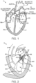
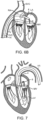
- FIGs 1 and 2 show a normal heart H.
- the heart comprises a left atrium that receives oxygenated blood from the lungs via the pulmonary veins PV and pumps this oxygenated blood through the mitral valve MV into the left ventricle LV.
- the left ventricle LV of a normal heart H in systole is illustrated in Figure 2 .
- the left ventricle LV is contracting and blood flows outwardly through the aortic valve AV in the direction of the arrows.
- Back flow of blood or "regurgitation" through the mitral valve MV is prevented since the mitral valve is configured as a "check valve" which prevents back flow when pressure in the left ventricle is higher than that in the left atrium LA.
- the mitral valve MV comprises a pair of leaflets having free edges FE which meet evenly, or "coapt" to close, as illustrated in Figure 2 .
- the opposite ends of the leaflets LF are attached to the surrounding heart structure via an annular region of tissue referred to as the annulus AN.
- Figure 3 is a schematic cross-sectional side view of an annulus and leaflets of a mitral valve. As illustrated, the opposite ends of the leaflets LF are attached to the surrounding heart structure via a fibrous ring of dense connective tissue referred to as the annulus AN, which is distinct from both the leaflet tissue LF as well as the adjoining muscular tissue of the heart wall.
- the leaflets LF and annulus AN are comprised of different types of cardiac tissue having varying strength, toughness, fibrosity, and flexibility. Furthermore, the mitral valve MV may also comprise a unique region of tissue interconnecting each leaflet LF to the annulus AN, referred to herein as leaflet/annulus connecting tissue LAC (indicated by overlapping cross-hatching). In general, annular tissue AN is tougher, more fibrous, and stronger than leaflet tissue LF.
- chordae tendineae CT which include a plurality of branching tendons secured over the lower surfaces of each of the valve leaflets LF.
- the chordae CT in turn, are attached to the papillary muscles PM, which extend upwardly from the lower wall of the left ventricle LV and interventricular septum IVS.
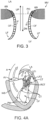
- a number of structural defects in the heart can cause mitral valve regurgitation.
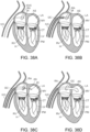
- Ruptured chordae RCT as shown in Figure 4A , can cause a valve leaflet LF2 to prolapse since inadequate tension is transmitted to the leaflet via the chordae. While the other leaflet LF1 maintains a normal profile, the two valve leaflets do not properly meet and leakage from the left ventricle LV into the left atrium LA will occur, as shown by the arrow.
- Regurgitation also occurs in the patients suffering from cardiomyopathy where the heart is dilated and the increased size prevents the valve leaflets LF from meeting properly, as shown in Figure 4B .
- the enlargement of the heart causes the mitral annulus to become enlarged, making it impossible for the free edges FE to meet during systole.
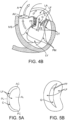
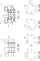
- the free edges of the anterior and posterior leaflets normally meet along a line of coaptation C as shown in Figure 5A , but a significant gap G can be left in patients suffering from cardiomyopathy, as shown in Figure 5B .
- Mitral valve regurgitation can also occur in patients who have suffered ischemic heart disease where the functioning of the papillary muscles PM is impaired, as illustrated in Figure 4A .
- the papillary muscles PM do not contract sufficiently to effect proper closure.
- One or both of the leaflets LF1 and LF2 then prolapse. Leakage again occurs from the left ventricle LV to the left atrium LA.
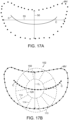
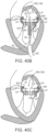
- Figures 5A-5C further illustrate the shape and relative sizes of the leaflets L of the mitral valve.
- the overall valve has a generally "D"- or kidney-like shape, with a long axis MVA1 and a short axis MVA2.
- the long axis MVA1 is typically within a range from about 33.3 mm to about 42.5 mm in length (37.9 +/- 4.6 mm)
- the short axis MVA2 is within a range from about 26.9 to about 38.1 mm in length (32.5 +/- 5.6 mm).
- MVA1 can be within a range from about 45 mm to 55 mm and MVA2 can be within a range from about 35 mm to about 40 mm.
- the line of coaptation C is curved or C-shaped, thereby defining a relatively large anterior leaflet AL and substantially smaller posterior leaflet PL ( Figure 5A ). Both leaflets appear generally crescent-shaped from the superior or atrial side, with the anterior leaflet AL being substantially wider in the middle of the valve than the posterior leaflet. As illustrated in Figure 5A , at the opposing ends of the line of coaptation C the leaflets join together at corners called the anterolateral commissure AC and posteromedial commissure PC, respectively.
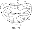
- Figure 5C shows the shape and dimensions of the annulus of the mitral valve.
- the annulus is an annular area around the circumference of the valve comprised of fibrous tissue which is thicker and tougher than that of the leaflets LF and distinct from the muscular tissue of the ventricular and atrial walls.
- the annulus may comprise a saddle-like shape with a first peak portion PP1 and a second peak portion PP2 located along an interpeak axis IPD, and a first valley portion VP1 and a second valley portion VP2 located along an intervalley axis IVD.
- the first and second peak portion PP1 and PP2 are higher in elevation relative to a plane containing the nadirs of the two valley portions VP1, VP2, typically being about 8-19 mm higher in humans, thus giving the valve an overall saddle-like shape.
- the distance between the first and second peak portions PP1, PP2, referred to as interpeak span IPD, is substantially shorter than the intervalley span IVD, the distance between first and second valley portions VP1, VP2.
- the dimensions and physiology of the patient may vary among patients, and although some patients may comprise differing physiology, the teachings as described herein can be adapted for use by many patients having various conditions, dimensions and shapes of the mitral valve.
- work in relation to embodiments suggests that some patients may have a long dimension across the annulus and a short dimension across the annulus without well-defined peak and valley portions, and the methods and device as described herein can be configured accordingly.
- Access to the mitral valve or other atrioventricular valve can be accomplished through the patient's vasculature in a percutaneous manner.
- percutaneous it is meant that a location of the vasculature remote from the heart is accessed through the skin, typically using a surgical cut down procedure or a minimally invasive procedure, such as using needle access through, for example, the Seldinger technique.
- the ability to percutaneously access the remote vasculature is well-known and described in the patent and medical literature.
- the approach to the mitral valve may be antegrade and may rely on entry into the left atrium by crossing the inter-atrial septum.
- approach to the mitral valve can be retrograde where the left ventricle is entered through the aortic valve.
- the interventional tools and supporting catheter(s) may be advanced to the heart intravascularly and positioned adjacent the target cardiac valve in a variety of manners, as described herein.
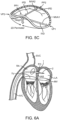
- a catheter 1 having a needle 2 may be advanced from the inferior vena cava IVC into the right atrium RA. Once the catheter 1 reaches the anterior side of the inter-atrial septum IAS, the needle 2 may be advanced so that it penetrates through the septum, for example at the fossa ovalis FO or the foramen ovate into the left atrium LA. At this point, a guidewire may be exchanged for the needle 2 and the catheter 1 withdrawn.
- access through the inter-atrial septum IAS may usually be maintained by the placement of a guide catheter 4, typically over a guidewire 6 which has been placed as described above.
- the guide catheter 4 affords subsequent access to permit introduction of the device to replace the mitral valve, as described in more detail herein.
- surgical access may be obtained through an intercostal incision, preferably without removing ribs, and a small puncture or incision may be made in the left atrial wall.
- a guide catheter may then be placed through this puncture or incision directly into the left atrium, sealed by a purse-string suture.
- the antegrade or trans-septal approach to the mitral valve can be advantageous in many respects.
- the use of the antegrade approach will usually allow for more precise and effective centering and stabilization of the guide catheter and/or prosthetic valve device. Precise positioning facilitates accuracy in the placement of the prosthetic valve device.
- the antegrade approach may also reduce the risk of damaging the subvalvular device during catheter and interventional tool introduction and manipulation. Additionally, the antegrade approach may decrease risks associated with crossing the aortic valve as in retrograde approaches. This can be particularly relevant to patients with prosthetic aortic valves, which cannot be crossed at all or without substantial risk of damage.
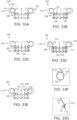
- the mitral valve MV may be accessed by an approach from the aortic arch AA, across the aortic valve AV, and into the left ventricle LV below the mitral valve MV.
- the aortic arch AA may be accessed through a conventional femoral artery access route, as well as through more direct approaches via the brachial artery, axillary artery, radial artery, or carotid artery. Such access may be achieved with the use of a guidewire 6. Once in place, a guide catheter 4 may be tracked over the guidewire 6.
- a surgical approach may be taken through an incision in the chest, preferably intercostally without removing ribs, and placing a guide catheter through a puncture in the aorta itself.
- the guide catheter 4 affords subsequent access to permit placement of the prosthetic valve device, as described in more detail herein.
- a retrograde arterial approach to the mitral valve may be choosen due to certain advantages.
- use of the retrograde approach can eliminate the need for a trans-septal puncture.
- the retrograde approach is also more commonly used by cardiologists and thus has the advantage of familiarity.
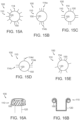
- FIG. 9 An additional approach to the mitral valve is via trans-apical puncture, as shown in Figure 9 .
- access to the heart is gained via thoracic incision, which can be a conventional open thoracotomy or sternotomy, or a smaller intercostal or sub-xyphoid incision or puncture.
- An access cannula is then placed through a puncture, sealed by a purse-string suture, in the wall of the left ventricle at or near the apex of the heart.
- the catheters and prosthetic devices of the invention may then be introduced into the left ventricle through this access cannula.
- the trans-apical approach has the feature of providing a shorter, straighter, and more direct path to the mitral or aortic valve. Further, because it does not involve intravascular access, the trans-apical procedure can be performed by surgeons who may not have the necessary training in interventional cardiology to perform the catheterizations required in other percutaneous approaches.
- the prosthetic treatment device may be specifically designed for the approach or interchangeable among approaches.
- a person of ordinary skill in the art can identify an appropriate approach for an individual patient and design the treatment apparatus for the identified approach in accordance with embodiments described herein.
- Orientation and steering of the prosthetic valve device can be combined with many known catheters, tools and devices. Such orientation may be accomplished by gross steering of the device to the desired location and then refined steering of the device components to achieve a desired result.
- Gross steering may be accomplished by a number of methods.
- a steerable guidewire may be used to introduce a guide catheter and the prosthetic treatment device into the proper position.
- the guide catheter may be introduced, for example, using a surgical cut down or Seldinger access to the femoral artery in the patient's groin. After placing a guidewire, the guide catheter may be introduced over the guidewire to the desired position. Alternatively, a shorter and differently shaped guide catheter could be introduced through the other routes described above.
- a guide catheter may be pre-shaped to provide a desired orientation relative to the mitral valve.
- the guide catheter may have a curved, angled or other suitable shape at its tip to orient the distal end toward the mitral valve from the location of the septal puncture through which the guide catheter extends.
- guide catheter 4 may have a pre-shaped J-tip which is configured so that it turns toward the mitral valve MV after it is placed over the aortic arch AA and through the aortic valve AV.
- the guide catheter 4 may be configured to extend down into the left ventricle LV and to assume a J-shaped configuration so that the orientation of an interventional tool or catheter is more closely aligned with the axis of the mitral valve MV.
- a pre-shaped guide catheter may be configured to be straightened for endovascular delivery by means of a stylet or stiff guidewire which is passed through a lumen of the guide catheter.
- the guide catheter might also have pull-wires or other means to adjust its shape for more fine steering adjustment.
- Embodiments of the present technology as described herein can be used to treat one or more of the valves of the heart as described herein, and in particular embodiments, can be used for treatment of the mitral valve.
- Examples of prosthetic heart valve devices, system components and associated methods in accordance with embodiments of the present technology are described in this section with reference to Figures 10A-40C . It will be appreciated that specific elements, substructures, advantages, uses, and/or other features of the embodiments described with reference to Figures 10A-40C can be suitably interchanged, substituted or otherwise configured with one another in accordance with additional embodiments of the present technology. Furthermore, suitable elements of the embodiments described with reference to Figures 10A-40C can be used as stand-alone and/or self-contained devices.
- the artificial replacement valve can be a prosthetic valve device suitable for implantation and replacement of a mitral valve between the left atrium and left ventricle in the heart of a patient.
- the prosthetic valve device can be suitable for implantation and replacement of another valve (e.g., a bicuspid or tricuspid valve) in the heart of the patient.
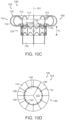
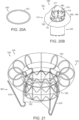
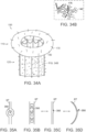
- Figure 10A shows an isometric view of a prosthetic heart valve device 100 in an expanded configuration 102 in accordance with an embodiment of the present technology
- Figure 10B is a schematic illustration of a cross-sectional view of a heart depicting the left atrium, left ventricle, and native mitral valve of the heart.
- Figure 10B also shows an embodiment of the expandable prosthetic valve device 100 implanted in the native mitral valve region of the heart.
- the device 100 can include an expandable retainer 110 at least partially surrounding and coupled to an inner valve support 120.
- the device 100 can further include a prosthetic valve 130 coupled to, mounted within, or otherwise carried by the valve support 120.
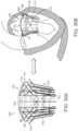
- Figures 10C-10D are side and top views, respectively, of the prosthetic heart valve device 100 in accordance with the present technology.
- the device 100 can also include one or more sealing members 140 that can extend around an inner surface 141 or outer surface 142 (as shown) of the retainer 110 and/or around an interior surface 126 (shown in Figure 10D ) or exterior surface 127 (shown in Figure 10A ) of the valve support 120 to prevent paravalvular (e.g., paraprosthetic) leaks between the device 100 and the native tissue and/or between the retainer 110 and the valve support 120.
- paravalvular e.g., paraprosthetic
- the prosthetic heart valve device 100 can be movable between a delivery configuration (not shown), an expanded configuration 102 ( Figure 10A ), and a deployed configuration 104 ( Figure 10B ).
- the prosthetic heart valve device 100 has a low profile suitable for delivery through small-diameter guide catheters positioned in the heart via the trans-septal, retrograde, or trans-apical approaches described herein.
- the delivery configuration of the prosthetic heart valve device 100 will preferably have an outer diameter no larger than about 8-10 mm for trans-septal approaches, about 8-10 mm for retrograde approaches, or about 8-12 mm for trans-apical approaches to the mitral valve MV.
- expansion configuration refers to the configuration of the device when allowed to freely expand to an unrestrained size without the presence of constraining or distorting forces.
- Delivery configuration refers to the device once expanded at the native valve site and subject to the constraining and distorting forces exerted by the native anatomy.
- a subannular surface of the mitral valve MV is a tissue surface lying on the ventricular side of the plane PO, and preferably one that faces generally downstream, toward the left ventricle LV.
- the subannular surface may be disposed on the annulus AN itself or the ventricular wall behind the native leaflets LF, or it may comprise a surface of the native leaflets LF, either inward-facing IF or outward-facing OF, which lies below the plane PO.
- the subannular surface or subannular tissue may thus comprise the annulus AN itself, the native leaflets LF, leaflet/annulus connective tissue, the ventricular wall or combinations thereof.
- the prosthetic heart valve device 100 can be intravascularly delivered to a desired location in the heart, such as an intracardiac location near the mitral valve MV, while in the delivery (e.g., collapsed) configuration within a delivery catheter (not shown).
- a desired location in the heart such as an intracardiac location near the mitral valve MV
- the device 100 can be advanced to a position within or downstream of the native annulus AN where the device 100 can be released from the delivery catheter to enlarge toward the expanded configuration 102 ( Figure 10A ).
- the device 100 will engage the native tissue at the desired location, which will deform or otherwise alter the shape of the device 100 into the deployed configuration 104 ( Figure 10B ).
- the device 100 can be positioned such that at least a portion of the expandable retainer 110 engages a subannular surface of the native valve so as to resist systolic forces and prevent upstream migration of the device 100 ( Figure 10B ).
- an upstream perimeter 113 of the retainer 110 engages the inward-facing surfaces IF ( Figure 3 ) of the native leaflets LF, which are pushed outwardly and folded under the native annulus AN.
- the leaflets LF engage a ventricular side of the annulus AN and are prevented from being pushed further in the upstream direction, thus maintaining the retainer 110 below the plane of the native valve annulus.
- some portions of the retainer 110 may extend above the annulus AN, with at least some portions of the retainer 110 engaging tissue in a subannular location to prevent migration of the device 100 toward the left atrium LA.
- the leaflets LF can lie in apposition against the outer surface 142 of the retainer 110 forming a blood-tight seal with the sealing member 140.
- the expandable retainer 110 while in a deployed configuration 104, conforms to the irregularly-shaped mitral annulus AN, effectively sealing the device 100 against the native annulus AN to anchor the device and to prevent paravalvular leaks.
- the retainer 110 mechanically isolates the valve support 120 from distorting forces present in the heart such that the retainer 110 may adapt and/or conform to native forces while the valve support 120 maintains its structural integrity.
- the retainer 110 can be sufficiently flexible and resilient and/or coupled to the valve support 120 in such a manner as to mechanically isolate the valve support 120 from the forces exerted upon the retainer 110 by the native anatomy.
- the valve support 120 may be more rigid and/or have greater radial strength than the radial strength of the retainer 110 so as to maintain its cylindrical or other desired shape and to ensure proper opening and closing of the prosthetic valve 130 housed within the valve support structure 120.
- the valve support 120 has a radial strength of at least 100%, or in other embodiments at least 200%, and in further embodiments at least 300%, greater than a radial strength of the retainer 110.
- the valve support 120 can have a radial strength of approximately 10N to about 12 N.
- valve support 120 can exhibit a hoop force which is about 2 to about 20 times greater for a given degree of deformation than will be exhibited by the retainer 110.
- the retainer 110 comprises a flexible, upstream portion of the device 100 and is implanted such that at least a portion of the retainer 110 engages tissue at or near the native mitral annulus.
- the retainer 110 can be a generally outward oriented portion of the device 100, as shown in Figure 10C .
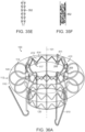
- the retainer 110 forms a donut-shaped flange 190 having an arcuate outer surface 142 for engaging tissue and an inner lumen defining a passage for blood to flow through the valve support 120.
- the outer surface 142 can have other shapes, such as linear, triangular, an irregular shape, etc.
- the retainer 110 can include a plurality of circumferentially positioned, resiliently deformable and flexible ribs 114 which are coupled at their downstream ends 116 to the valve support 120. Once deployed, at least a portion of the upstream region 118 of the flexible ribs 114 can expand outward from the valve support 120 to engage a surface at or near the native valve (e.g., mitral valve).
- a surface at or near the native valve e.g., mitral valve
- Figures 10A-10D also illustrate that the flexible ribs 114, in one embodiment, can have a general C-shape configuration with tips 117 of the flexible ribs 114 and opening 119 of the C-shape configuration oriented toward a longitudinal axis 101 of the device 100.
- the each individual flexible rib 114 can be independent or otherwise unconnected to any other (e.g., adjacent) flexible rib 114 of the retainer 110.
- the retainer 110 can have circumferential connectors connecting one or more flexible ribs 114 of the retainer 110.
- the flexible ribs 114 may be divided along their length into multiple, separated segments (shown below with respect to Figures 13A-13G ).
- the plurality of flexible ribs 114 can be formed from a deformable material or from a resilient or shape memory material (e.g., nitinol).
- the retainer 110 can comprise a mesh or woven construction in addition to or in place of the flexible ribs 114.
- the retainer 110 could include a plurality of flexible wires or filaments arranged in a diamond pattern or other configuration.
- the retainer 110 can be formed of a pre-shaped nitinol tube having, for example, a wall thickness of approximately 0.010 inches to about 0.130 inches.
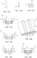
- Figure 11 shows an embodiment of the valve support 120 that can be used in the various embodiments of the prosthetic heart valve device 100 shown in Figures 10A-10D .
- Figure 11 is an isometric view of the valve support 120 shown in an expanded configuration 102 in accordance with the present technology.
- several embodiments of the valve support 120 can be generally cylindrical having an upstream end 121 and a downstream end 123 formed around the longitudinal axis 101 with a circular, oval, elliptical, kidney-shaped, D-shaped, or other suitable cross-sectional shape configured to support a tricuspid or other prosthetic valve 130.
- the valve support 120 includes a plurality of posts 122 connected circumferentially by a plurality of struts 124.
- the posts 122 and struts 124 can be arranged in a variety of geometrical patterns that can expand and provide sufficient resilience and column strength for maintaining the integrity of the prosthetic valve 130.
- the plurality of posts 122 can extend longitudinally across multiple rows of struts 124 to provide column strength to the valve support 120.
- the valve support 120 can include a metallic, polymeric, or fabric mesh or woven construction.
- the plurality of posts 122 can extend along an axial direction generally parallel to the longitudinal axis 101 and the struts 124 can extend circumferentially around and transverse to the longitudinal axis 101.
- the posts 122 can extend an entire longitudinal height H 1 (shown in Figure 10C ) of the valve support 120 and in one embodiment the height H 1 can be approximately 14 mm to about 17 mm.
- the struts 124 can form a series of rings around the longitudinal axis 101, wherein each ring has a circumferentially expandable geometry.
- the struts 124 are formed in a series of zig-zags to form a chevron configuration.
- Alternative expandable geometries can include sinusoidal patterns, diamond configurations, closed cells, open cells, or other expandable configurations.
- the plurality of struts 124 can attach to the plurality of posts 122 so as to define a plurality of nodes 125 where the struts and posts intersect.
- the plurality of struts 124 and the plurality of posts 122 can be formed from a deformable material or from a resilient or shape memory material (e.g., nitinol).
- the valve support 120 has the interior surface 126 and the exterior surface 127, and the valve support 120 is configured to receive the prosthetic valve 130 within an interior lumen of the valve support 120 to inhibit retrograde blood flow (e.g., blood flow from the left ventricle into the left atrium).
- the valve support 120 can provide a scaffold to which prosthetic valve tissue can be secured and provide a scaffold that has sufficient axial rigidity to maintain a longitudinal position of the prosthetic valve 130 relative to the retainer 110.
- the valve support 120 can further provide such a scaffold having radial rigidity to maintain circularity (or other desired cross-sectional shape) to ensure that leaflets 132 of the prosthetic valve 130 coapt or otherwise seal when the device 100 is subject to external radial pressure.
- valve support 120 can have a support region 145 along the longitudinal axis 101 that is configured to attach to the prosthetic valve, or in other embodiments, be aligned with the coaptation portion of the leaflets 132 (shown in Figure 11 ).
- the valve 130 may comprise a temporary or permanent valve adapted to block blood flow in the upstream direction and allow blood flow in the downstream direction through the valve support 120.
- the valve 130 may also be a replacement valve configured to be disposed in the valve support 120 after the device 100 is implanted at the native mitral valve.
- the leaflets 132 may be formed of various flexible and impermeable materials including PTFE, Dacron ® , pyrolytic carbon, or other biocompatible materials or biologic tissue such as pericardial tissue or xenograft valve tissue such as porcine heart tissue or bovine pericardium. Other aspects of valve 130 are described further below.
- the interior surface 126 within the lumen of the valve support 120 can be covered at least partially by an impermeable sealing member 140 to prevent blood flow from inside the valve support 120 to the outside of the valve support 120, where it could leak around the exterior of the valve support 120.
- the sealing member 140 may be affixed to the exterior surface 127 of the valve support 120 and, in either embodiment, may be integrally formed with or attached directly to valve 130.
- the sealing member 140 can be applied on at least portions of both the interior surface 126 and the exterior surface 127 of the valve support 120.
- the prosthetic valve 130 can be sutured, riveted, glued, bonded, or otherwise fastened to posts 122 or commissural attachment structures 128, which are configured to align with valve commissures C.
- the posts 122 or commissural attachment structures 128 can include eyelets 129, loops, or other features formed thereon to facilitate attachment of sutures or other fastening means to facilitate attachment of the prosthetic valve 130.
- the attachment structures 128 can be integrated into the structural frame of the valve support 120 such that the attachment structures 128 are distributed around the circumference of the valve support 120 and function as posts 122.
- the attachment structures 128 can be attachment pads formed on parts of the posts 122 (e.g., along an upper end of the posts 122) or can be separate structures that can be coupled to posts 122, struts 124 or other components along the interior surface 126 of the valve support 120.
- the prosthetic valve 130 may also be attached to the sealing member 140, which can be a sleeve attached to the interior surface 126 of the valve support 120.
- the prosthetic valve 130 can be suitable to collapse or compress with the device 100 for loading into a delivery catheter (not shown).
- the prosthetic valve 130 has a tri-leaflet configuration, although various alternative valve configurations may be used, such as a bi-leaflet configuration.
- the design of the prosthetic valve 130 such as the selection of tri-leaflet vs. bi-leaflet configurations, can be used to determine the suitable shape of the valve support 120.
- the valve support 120 can have a circular cross-section, while for a bi-leaflet valve, alternative cross-sectional shapes are possible such as oval or D-shaped cross-sections.
- the valve support can have a circular cross-sectional diameter of approximately 25 mm to about 30 mm, such as 27 mm.
- the valve support 120 can have a permanent prosthetic valve pre-mounted therein, or the valve support 120 may be configured to receive a separate catheter-delivered valve following implantation of the device 100 at the native mitral valve.
- the valve support 120 can further include a temporary valve pre-mounted within the interior lumen. If a period of time between placement of the device 100 and further implantation of the permanent prosthetic valve is desirable, a temporary valve sewn into or otherwise secured within the valve support 120 can assure regulation of blood flow in the interim. For example, temporary valves may be used for a period of about 15 minutes to several hours or up to a several days.
- Permanent or replacement prosthetic valves may be implanted within a temporary valve or may be implanted after the temporary valve has been removed.
- pre-assembled, percutaneous prosthetic valves include, e.g., the CoreValve ReValving ® System from Medtronic/Corevalve Inc. (Irvine, CA, USA), or the Edwards-Sapien ® valve from Edwards Lifesciences (Irvine, CA, USA).
- the valve support 120 may have features within its interior lumen or on its upper or lower ends to engage and retain the catheter-delivered valve therein, such as inwardly extending ridges, bumps, prongs, or flaps.
- a downstream portion 111 of the retainer 110 can be coupled to or near the upstream end 121 of the valve support 120 and extend outward and in an upstream direction from the valve support 120 in a manner that does not unduly influence the shape of the valve support 120. Accordingly, in some embodiments, the retainer 110 can be configured to engage and deform to the shape of the native tissue on or under the annulus while a cross-sectional shape of the valve support 120 remains sufficiently stable or substantially undeformed.
- the valve support 120 (e.g., at least at the upstream end 121) can be spaced longitudinally downstream from at least a tissue engaging portion 112 of the retainer 110 such that if the retainer 110 is deformed inwardly, the cross-sectional shape of the valve support 120, which remains positioned downstream of the tissue engaging portion 112 of the retainer 110, remains substantially undeformed.
- substantially undeformed can refer to situations in which the valve support 120 is not engaged or deformed, or can refer to scenarios in which the valve support 120 can deform slightly but the prosthetic valve 130 remains intact and competent (e.g., the leaflets 132 coapt sufficiently to prevent retrograde blood flow). In such arrangements, leaflets 132 of the prosthetic valve 130 can close sufficiently even when the device 100 is under systolic pressures or forces from the pumping action of the heart.
- the retainer 110 can be coupled to or near the upstream end 121 of the valve support 110 the valve support 120 in such that the valve support 120 and valve 130 reside within the left ventricle.
- the retainer 110 can be coupled to the valve support 120 anywhere along a length of the valve support 120 such that the valve support 120 and valve 130 can reside within the annulus or above the annulus of the native heart valve.
- the valve support 120 and retainer 110 may be coupled by a variety of methods known in the art, e.g., suturing, soldering, welding, bonding, staples, rivets or other fasteners, mechanical interlocking, friction, interference fit, or any combination thereof.
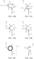
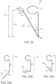
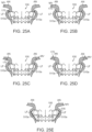
- Figures 12A-12H are side views of additional mechanisms of coupling the valve support 120 to the retainer 110 that can allow mechanical isolation of the valve support 120 from the retainer 110 in accordance with additional embodiments of the present technology.
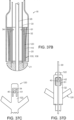
- the flexible ribs 114 can include rib posts 88 ( Figure 12A ) that can be coupled to valve support posts 122 ( Figure 12C ) using individual hypotubes 108 (shown in Figure 12B ).
- the rib post 88 may be aligned with the individual valve support posts 122 and the hypotube 112 may be slipped over both the valve support posts 122 and the rib posts 88.
- the hypotubes 108 can be crimped or otherwise adhered to valve support posts 122 and the rib posts 88 such that the flexible ribs 114 are connected to and aligned with valve support posts 122 in a manner that allows the tissue engaging portions 112 to extend outward and in an upstream direction from the valve support 120.
- a sealing member 140 or other overlaying structure may be attached to both the retainer 110 and the valve support 120 to interconnect the two structures.
- the valve support 120 can be covered by a sealing member 140, such as a sleeve 146 that includes a plurality of longitudinal pockets 109 formed (e.g., by suturing or bonding two layers of sleeve fabric together) or otherwise incorporated circumferentially around the sleeve 146.
- each individual rib 114 can be constrained within the pockets 109 formed in the sleeve 146, and the sleeve can be coupled to an interior or exterior surface 126, 127 of the valve support ( Figure 11 ).
- the valve support 120 and the retainer 110 can be integrally formed with one another.
- the flexible ribs 114 can be formed integrally with the posts 122 of the valve support 120 (shown in Figures 10C and 12F .
- the retainer 110 may include a retainer frame 165, separate from the frame of the valve support 120 ( Figure 12G ).
- the retainer frame 165 may include rib posts 88 connected circumferentially by deformable and/or flexible connectors 166, and can be configured to receive or partially surround the valve support 120 ( Figure 12H ).
- the retainer frame 165 can be delivered by catheter and deployed at a target site in the native heart valve and the valve support 120 can be delivered separately following deployment and implantation of the retainer frame 165.
- the retainer frame 165 can be configured to receive or be coupled to the support frame 120 prior to delivery of the device 100 to the target site.
- the flexible ribs 114 can be less rigid than the posts 122 and/or struts 124 of the valve support 120, allowing greater flexibility in the retainer 110 and/or more stability to the shape and position of the valve support 120.
- the flexibility of the retainer 110 can allow the retainer 110 to absorb distorting forces as well as allow the device 100 to conform to the irregular, non-circular shape of the native annulus (while leaving the valve support 120 substantially unaffected), encouraging tissue ingrowth and creating a seal to prevent leaks between the device 100 and the native tissue.
- the flexible ribs 114 can be configured to press radially outward against the native valve, ventricular and/or aortic structures so as to anchor the device 100 in a desired position, as well as maintain an upstream deployed circumference 150' larger than that of the native annulus such that subannular positioning effectively prevents upstream migration of the device 100 (described further below in Figure 18C).
- the flexible ribs 114 can have sufficient resilience and column strength (e.g., axial stiffness) to prevent longitudinal collapse of the retainer 110 and/or the device 100 and to resist movement of the device 100 in an upstream direction.
- valve 130 and valve support 120 are effectively mechanically isolated from the distorting forces exerted on the retainer 110 by the native tissue, e.g., radially compressive forces exerted by the native annulus and/or leaflets, longitudinal diastolic and systolic forces, hoop stress, etc.
- deformation of the retainer 110 by the native tissue can change a cross-section of the retainer 110 (e.g., to a non-circular or non-symmetrical cross-section), while the valve support 120 may be substantially undeformed.
- valve support 120 can be deformed by the radially compressive forces, for example, where the retainer 110 is coupled to the valve support 120 (e.g., the downstream end 123).
- the upstream end 121 of the valve support 120 and/or the valve support region 145 ( Figure 11 ) is mechanically isolated from the retainer 110 and the compressive forces such that at least the valve support region 145 can be substantially undeformed.
- the valve support 120, and at least the valve support region 145 can maintain a circular or other desirable cross-section so that the valve remains stable and/or competent.
- the flexibility of the ribs 114 can contribute to the absorption of the distorting forces, and also aid in mechanically isolating the valve support 120 and valve 130 from the retainer 110 and from the native anatomy.
- the retainer 110 is comprised of a series of circumferentially positioned flexible ribs 114 which are coupled or otherwise integrated at their downstream ends 116 to the valve support 120.
- the flexible ribs 114 may not be circumferentially connected by struts which can allow for greater movement, flexing, bending, rotating and/or deformation of the individual ribs 114 and the retainer 110 as a whole.
- the retainer 110 did include circumferential struts or supports (not shown) for retaining or connecting the ribs 114, the struts may be more flexible than the struts 124 utilized in the valve support 120.
- Figures 13A-13G are partial side views of a variety of flexible rib configurations in accordance with additional embodiments of the present technology.
- the ribs 114 in one embodiment, can generally have an arcuate or C-shaped tissue engaging portion 112 and include the rib post 88 at the downstream end 116 of the rib 114.
- the rib post 88 can be generally linear and have a suitable length L R1 for extending the retainer 110 a desirable distance upstream from a connection (not shown) to the valve support 120.
- the rib post 88 can be generally parallel to the longitudinal axis 101 of the device 100 and/or valve support 120 (shown in Figure 10C ).
- a first segment 80 of the tissue engaging portion 112 can extend radially outward from the rib post 88 beginning at a first transition 82.
- the first transition 82 can be a curved or U-shaped section as shown to orient the first segment 82 outward from the rib post 88.
- the first segment 80 can be arcuate or generally curved in an outward and upstream direction to reach a second transition 84.
- a second segment 86 of the tissue engaging portion 112 can be arcuate or generally curved and extend (e.g., relative to the rib post 88) from the second transition 84 in an upstream and inward direction.
- the second segment 86 can also curve slightly downstream at the rib tip 117.
- the opening 119 of the C-shaped tissue engaging portion 112 of the rib 114 is created in the space between the first transition 82 and the rib tip 117.
- rib segments such as the first and second segments 80, 86, can be generally linear ( Figures 13B-13E ).
- Other embodiments of tissue engaging portion 112 can have transitions 82 and 84 with less curvature or greater curvature.
- the first transition segment 82 may comprise a curved section with a distinct inflection point (shown in Figures 13A and 13C-13E ) or a short continuous segment with a constant radial curve ( Figure 12B ).
- the tissue engaging portion 112 can also include additional transitions and/or segments to form desirable rib shapes, such as generally square-shaped ( Figure 13B ), or generally triangularshaped ( Figures 13C-13E ) tissue engaging portions 112. Similar to the embodiment of the tissue engaging portion 112 shown in Figure 13A , the tissue engaging portion 112 shown in Figures 13B-13E have the openings 119 which can face inward toward a retainer interior (shown in Figures 10A-10D ); however, one of ordinary skill in the art will recognize that the ribs 114 can be oriented in a different direction, such as having the opening 119 facing outward with respect the longitudinal axis 101 of the device 100 (not shown). Additional embodiments of the tissue engaging portion 112 can be formed without openings 119.
- additional transitions and/or segments to form desirable rib shapes such as generally square-shaped ( Figure 13B ), or generally triangularshaped ( Figures 13C-13E ) tissue engaging portions 112. Similar to the embodiment of the tissue engaging portion 112 shown in Figure 13A ,
- the tissue engaging portion 112 may take on other unique geometries. As shown in Figure 12F , the tissue engaging portion 112 may coil or extend around an axis 90 transverse to the longitudinal axis 101. Or, as shown in Figure 12G , the tissue engaging portion 112 may have multiple segments extending radially outward and/or multiple segments extending radially inward with respect to the rib post 88 in an irregular or in a patterned configuration.
- the tissue engaging portion 112 can have a height H 1 between an upper surface 74 and a lower surface 76. Accordingly, in addition to the shape of the tissue engaging portion 112, the overall height H 1 of the tissue engaging portion 112 can be selected to accommodate the anatomy at the desired target location of the heart valve.
- the tissue engaging portion 112 of the rib 114 can be configured to absorb, translate and/or mitigate distorting forces present with the heart during, for example, systole and diastole.
- the shape of the tissue engaging portion 112 can be selected to accommodate forces, such as radially compressive forces, e.g., exerted by the native annulus and/or leaflets Fa, longitudinal diastolic Fd and systolic Fs forces, hoop stress, etc. Absorption of the distorting forces can serve to mechanically isolate the retainer 110 from the valve support 120.
- the ribs 114 may flex, bend, rotate or twist under the distorting forces while the valve support 120 substantially maintains its rigidity and/or original shape (e.g., a generally circular shape).
- the device 100 can include a tricuspid valve 130 retained within a generally circular valve support 120 ( Figures 10A-11 ). When deployed and operational, the cross-sectional shape of the valve support 120 can remain sufficiently stable when the retainer 110 is deformed in a non-circular shape by engagement with the tissue such that the valve 130 remains competent.
- Figures 14A-14J are side views of various flexible ribs 114 flexing in response to a distorting force F in accordance with further embodiments of the present technology.
- the degree of flexibility of individual ribs 114 (and thus the retainer 110) may be consistent among all ribs 114 of a retainer 110, or, alternatively, some ribs 114 may be more flexible than other ribs 114 within the same retainer 110.
- a degree of flexibility of individual ribs 114 may be consistent throughout an entire length of the rib 114 or curvature of the tissue engaging portion 112, or the degree of flexibility can vary along the length and/or curvature of each rib 114.
- the tissue engaging portions 112 of the ribs 114 may flex relative to the rib post 88 in response to varying distorting forces F that can be applied by the surrounding tissue during or after implantation of the device 100. From a static position ( Figure 14A ), the tissue engaging portion 112a may flex downward to a position 112b ( Figure 14B ) or upward to a position 112c ( Figure 14C ) in response to a downward force F 1 or an upward force F 2 , respectively.
- the tissue engaging portion 112a may flex inward to a position 112d ( Figure 14D ) or outward to a position 112e ( Figure 14E ) in response to a laterally directed inward force F 3 or a laterally directed outward force F 4 , respectively.
- the tissue engaging portion 112a may flex and/or rotate inwardly/outwardly in response to the laterally directed forces F 3 , F 4 , or upward/downward in response to the generally vertically directed forces F 1 , F 2 without altering the general shape of the tissue engaging portion 112.
- the position of the tissue engaging portion 112 can occur by flex or rotation around the first transition 82 ( Figures 14A-14E ).
- the rib 114 can be configured to alter the shape of the tissue engaging portion 112a in response to forces, such as to the shape/position 112f in response to the downward force F 1 ( Figure 14F ) and to the shape/position 112g in response to the upward force F 2 ( Figure 14G ). Alteration of the shape and/or position of the tissue engaging portion 112, as shown in Figures 14F-14G , may occur by flexing, rotating and/or deformation around segments 80, 86 and/or transitions 82, 84, for example.
- the tissue engaging portion 112a may also flex and/or rotate laterally (e.g., to positions 112i or 112j) in response to a laterally-directed force F 5 , by bending at transition 82, for example, at unique and variable splay angles A S off a midline 89 such that the rib tips 117 may be splayed away from each other.
- FIGS 15A-15E are schematic top views of the prosthetic heart valve device 100 showing a variety of rib configurations in accordance with further embodiments of the present technology.
- Figure 15A shows and embodiment of the device 100 having a plurality of ribs 114 symmetrically and evenly spaced around the circumference 150 of the retainer 110.
- the device 100 can include a first plurality of ribs 114a and second plurality of ribs 114b ( Figure 15B ).
- the first plurality of ribs 114a can have a characteristic different than the second plurality of ribs 114b.
- Various characteristics could include size of the rib, rib shape, rib stiffness and the number of ribs 114 within a given area of the retainer 110.
- the retainer 110 can include multiple groups of ribs 114 spaced symmetrically ( Figure 15C ) or asymmetrically ( Figure 15D ) around the circumference 150 of the retainer 110.
- the groups of ribs 114c and 114e may include different numbers of ribs 114 than in other groups (e.g., 114d).
- the ribs 114 can be unevenly spaced around the circumference 150 of the retainer 110 ( Figures 15E ).
- the retainer 110 can include, in one embodiment, between approximately 2 ribs to about 30 ribs, and in another embodiment, between approximately 6 ribs to about 20 ribs.
- Figures 16A-16B are schematic side and cross-sectional views of the prosthetic heart valve device 100 showing additional embodiments of the retainer 110 in accordance with the present technology.
- the retainer 110 can be formed from a self-expanding mesh 180 or weave of material formed from a deformable material or a resilient or shape memory material (e.g., nitinol) that can evert ( Figure 16A ) or that can roll ( Figure 16B ) to form the retainer 110.
- the retainer 110 can comprise the self-expanding mesh or woven construction in addition to the flexible ribs 114.
- the self-expanding mesh 180 could include a plurality of flexible wires or filaments arranged in a diamond pattern ( Figure 16A ) or other configuration.
- the retainer 110 can be formed of a pre-shaped nitinol tube having, for example, a wall thickness of approximately 0.010 inches to about 0.130 inches.
- FIG 17A is a schematic top view of a native mitral valve MV illustrating the minor axis 50 and major axis 55
- Figures 17B-17C are schematic top views of an retainer 110 in an expanded configuration 102 and in a deployed configuration 104, respectively, overlaying the schematic of the native mitral valve MV in accordance with an embodiment of the present technology.
- the retainer 110 can have an outer circumference 150 with a diameter D 1 that is greater than the minor axis 50 ( Figure 17A ) of the native annulus, and usually less than the major axis 55 of the annulus, when the retainer 110 is in an expanded configuration 102 (shown as dashed lines).
- the retainer 110 may have a diameter D 1 at least as large as the distance between the native commissures C, and may be as large as or even larger than the major axis 55 of the native annulus.
- the outer circumference 150 of the retainer 110 has the diameter D 1 which is approximately 1.2 to 1.5 times the diameter (not shown) of the valve support 120 (or the prosthetic valve 130 ), and can be as large as 2.5 times the diameter of the valve support 120 (or the prosthetic valve 130).
- the valve support 120 and the prosthetic valve 130 in accordance with aspects of the present technology, may be manufactured in just a single diameter to fit a multitude of native valve sizes.
- the valve support 120 and the prosthetic valve 130 do not need to engage and fit the native anatomy precisely.
- the valve support 120 may have a diameter (not shown) in the range of about 25mm to about 32 mm for adult human patients.
- the retainer 110 may be provided in multiple diameters or having a variable size circumference 150 to fit various native valve sizes, and may range in diameter from about 28 mm to about 80 mm, or in other embodiments, greater than 80 mm.
- the top view of the retainer 110 shown in Figure 17C illustrates how flexibility and/or deformation of one or more flexible ribs 114 and/or rib segments allows the retainer 110 to distort relative to the expanded configuration 102, as shown by the dashed lines, into a deployed configuration 104, as shown by the bolded lines.
- the retainer 110 when deployed or implanted at or under the mitral valve annulus, can conform to the highly variable native mitral valve tissue shape MV, as shown in the dotted lines.
- the ribs 114 can bend, twist, and stretch such that the overall shape of the retainer 110 has a deployed (e.g., a generally more oval or D-shaped, or other irregular shape) configuration 104 instead of a fully expanded configuration 102.
- a deployed configuration 104 e.g., a generally more oval or D-shaped, or other irregular shape
- the retainer 110 covers the mitral valve commissures C in the deployed configuration 104, whereas the commissures C would be left unsealed or exposed in the more circular expanded configuration 102, potentially allowing paravalvular leaks.
- the retainer 110 could also be pre-shaped to be in a generally oval or D-shape, or other shape, when in an unbiased condition.
- the retainer 110 can have sufficient flexibility such that the retainer 110 conforms to the native mitral annulus when in the deployed configuration 104 ( Figure 17C ), however, the retainer 110 can be configured to remain biased towards its expanded configuration 102 (e.g., Figures 10A and 17B ) such that, when in the deployed configuration 104, the retainer 110 pushes radially outwards against the native annulus, leaflets, and/or ventricular walls just below the annulus.
- the radial force generated by the biased retainer shape may be sufficient to deform the native anatomy such that the minor axis 50 ( Figure 17A ) of the native valve is increased slightly, and/or the shape of the annulus is otherwise altered.
- Such radial force can enhance anchoring of the device 100 to resist movement toward the atrium when the valve 130 is closed during ventricular systole as well as movement toward the ventricle when the valve 130 is open. Furthermore, the resulting compression fit between the retainer 110 and leaflets and/or ventricular walls or other structures helps create a long-term bond between the tissue and the device 100 by encouraging tissue ingrowth and encapsulation.
- Figure 18 is a side view of a prosthetic heart valve device 100 shown in an expanded configuration 102 in accordance with a further embodiment of the present technology.
- the device 100 can include features generally similar to the features of the prosthetic heart valve device 100 described above with reference Figures 10A-17C .
- the device 100 includes the valve support 120 and the prosthetic valve 130 housed within an interior lumen of the valve support 120.
- the device 100 includes a retainer 210 having an oval or D-shaped upstream perimeter 213 and a plurality of elevations around a circumference 250 of the retainer 210 such that the retainer 210 is suitable for engaging and conforming with tissue in the subannular region of the mitral valve.
- the tissue engaging portion 212 of the retainer 210 can be a generally outward oriented portion of the device 100.
- the retainer 110 can include of a series of circumferentially positioned, resiliently deformable and flexible ribs 214.
- the retainer 210 can include flexible wires or filaments arranged in a diamond pattern or configuration (not shown).
- the flexible ribs 214 can, in some embodiments, provide column strength sufficient to inhibit movement of the device 100 relative the annulus under the force of systolic blood pressure against the valve 130 mounted in the valve support 120.
- the upstream perimeter 213 of the retainer 210 does not lie in a single plane.
- the ribs 214 can have variable lengths and/or be off-set from each other at variable angles such that a distance (e.g., elevation) between a downstream perimeter 215 and the upstream perimeter 213 can vary around the circumference 250.
- the upstream perimeter 213 can form a rim having a plurality of peaks 251 and valleys 252 for adapting to the shape of the native mitral valve (see Figure 5C ).
- peaks” and “valleys” refers to portions of the upstream perimeter 213 having an undulating shape formed by changes in elevation with respect to the downstream perimeter 215.
- the peak portions of the upstream perimeter 213 are about 2 to about 20 mm, or more preferably about 5 mm to about 15 mm, higher (further upstream) than the valley portions relative to a reference plane perpendicular to the direction of blood flow through the valve.
- the upstream perimeter 213 of the retainer 210 can have two peaks 251 that are separated by two valleys 252.
- a first peak can have a different shape or elevation than that of a second peak.
- the shape of a valley 252 can be different than a shape of an inverted peak 251.
- the peaks 251 and valleys 252 can be asymmetrically positioned and shaped around the circumference 250 of the retainer 210.
- the valleys 252 can be configured for positioning along commissural regions of the native annulus
- the peaks 251 can be configured for positioning along leaflet regions of the native annulus.
- the peaks 251 can have apices configured to be positioned near midpoint regions of the leaflets.
- the valve support 120 can have sufficient rigidity to maintain a circular or other original cross-sectional shape, thus ensuring proper functioning of the prosthetic valve leaflets 132 when opening and closing.
- Such mechanical isolation from the retainer 210 may be achieved by the valve support 120 having sufficient rigidity to resist deformation while retainer 210 is deformed, and by selecting a location and means for coupling the valve support 120 to the retainer 210 so as to mitigate the transmission of forces through the retainer 210 to the valve support 120 or the prosthetic valve 130 contained therein.
- valve support 120 may be coupled to the retainer 210 only at the upstream end 121 of the valve support 120, and the retainer 110 can further extend away from the valve support in an outward and upstream direction.
- forces exerted on the retainer 210 by the annulus or subannular tissue can be absorbed by the flexible ribs 214 of the retainer 210 to mitigate transmission of such forces to the valve support 120.
- some embodiments of the prosthetic heart valve device 100 can include a sealing member 140 that extends around portions of the retainer 110 and/or the valve support 120.
- the embodiment illustrated in Figure 10A has a sealing member 140 around the outer surface 142 of the retainer 110 and around an exterior surface 127 of the valve support 120 to prevent paravalvular leaks both between the device 100 and the anatomy but also through components of the device 100.
- the sealing member 140 can be configured to promote ingrowth of tissue for facilitating implantation of the device 100 in the native heart valve.
- the sealing member can be a sleeve 146 ( Figure 10A ) which can include an impermeable sealing material that is cylindrical and configured to fit within or over various frame or skeleton structures of the device 100 as further described below.
- the sleeve 146 is on the exterior surface 127 of the valve support 120; however, in other embodiments, the sleeve 146 or other sealing member 140 can be disposed on the interior surface 126 of the valve support 120. While Figure 10A illustrates an embodiment of the device 100 in which the sleeve 146 is disposed on the outer surface 142 of the retainer 110, one of ordinary skill will recognize other configurations where the sleeve 146 can be disposed on the inner surface 141 of the retainer 110.
- sealing members 140 such as the sleeves 146
- the sealing members 140 can fully cover the surfaces 126, 127, 141 and 142 or in other embodiments, at least partially cover the surfaces 126, 127, 141 and 142 of the retainer 110 and the valve support 120, respectively. Any combination of sealing members 140 is contemplated.
- the sealing member 140 can comprise a single continuous sheet of fluid impervious material (e.g., for covering a surface 141, 142 of the retainer 110 and a surface 126, 127 of the valve support 120), which could create a seal between the retainer 110 and the valve support 120.
- the sealing member 140 such as the sleeve 146, can comprise a fabric or other flexible and biocompatible material such as Dacron ® , ePTFE, bovine pericardium, or other suitable flexible material to integrate with tissue and minimize paravalvular leaks.
- the sealing member 140 can include a polymer, thermoplastic polymer, polyester, Gore-tex ® , a synthetic fiber, a natural fiber or polyethylene terephthalate (PET).
- PET polyethylene terephthalate
- the valve 130 may also be attached to the sealing member 140 or integrally formed with the sealing member 140.
- the prosthetic heart valve device 100 can also include additional support features for maintaining a desired shape and/or rigidity of the valve support 120 or the retainer 110.
- Figure 19 is an isometric view of the prosthetic heart valve device 100 having a connecting ring 156 in accordance with an embodiment of the present technology.
- the connecting ring 156 can be coupled to plurality of commissure posts 158 integrated and/or coupled to the valve support 120.
- the connecting ring 156 can be coupled to the downstream ends 157 of the commissure posts 158; however, the connecting ring 156 may also be coupled to another portion of the commissure posts 158 or the valve support 120.
- the connecting ring 156 can have a variety of symmetrical or non-symmetrical geometrical cross-sections and can provide support for the commissure posts 158 to keep the posts from bending or deforming.
- Figures 20A-20B are isometric views of a retainer support ring 160 and the prosthetic heart valve device 100 having the retainer support ring 160 in accordance with an additional embodiment of the present technology.
- the retainer support ring 160 can be a circular-shaped ring element that has a ring circumference 151 approximately similar to a desired circumference 150 of the retainer 110 when the device 100 is in the expanded configuration 102.
- the support ring 160 can have a different shape (e.g., oval, D-shaped, irregular, etc.) such that the support ring 160 can be configured to encourage the retainer 110 into the different shape.
- the support ring 160 can be formed from a shape memory material (e.g., nitinol) that can collapse in a delivery configuration (not shown) to fit within a delivery catheter, and to expand toward the ring circumference 151 when the device 100 is deployed at the target location at or near the native heart valve.
- the retainer support ring 160 may be a solid, coiled, or woven wire or band of a flexible, resilient material (e.g., biocompatible polymers or metals) with the desired degree of rigidity.
- the sealing member 140 such as the sleeve 146, is pulled away for clarity only to expose the retainer support ring 160 disposed within the inner surface 141 of the retainer 110.
- the support ring 160 can be configured to be disposed in the openings 117 of the C-shaped ribs 114 of the retainer 110 to provide additional circumferential support for the retainer 110, enhance radial rigidity and to resist and distribute distorting forces exerted on the retainer 110 during and after delivery of the device 100.
- Figure 22 illustrates one embodiment of the prosthetic heart valve device 100 in an expanded configuration 102 that further comprises one or more stabilizing members 501 to help stabilize the device 100 at the native valve site and, in some embodiments, prevent tilting or lateral migration, or to inhibit upstream or downstream migration of the device 100.
- the stabilizing members 501 may comprise one or more arms 510 extending from a lower or downstream end 123 of the valve support 120, or from the commissure posts 158.
- the arms 510 can be configured to extend from a downstream end of rib posts 88 (shown in Figure 22 ).
- the arms 510 are configured to engage the native tissue, e.g. the valve leaflets, subannular tissue, or ventricular wall, either inside or outside the native leaflets, depending on the configuration.
- FIG 22 is an enlarged schematic, side view of a prosthetic heart valve device 100 having an extended arm in accordance with an embodiment of the present technology.
- an individual arm 510 may comprise an arm body 512, an arm extension 514, and an arm tip 516.
- the arm body 512 has an arm body length L 1 and may connect to a post 511 at a first joint 508.
- the post 511 can be a valve support post 122, a retainer rib post 88, and/or another feature of the device 100 (e.g., a commissure post 158).
- the arm body 512 may be welded, bonded, crimped, or otherwise mechanically attached to the post 511 the first joint 508.
- arms 510 may be integrally formed with posts 511, such as the valve support posts 122 or the rib posts 88.
- a first arm angle A A1 is formed by the intersection of the axes of post 511 and the arm body 512 and is selected such that the arm 512 is positionable so that the tip 516 can engage the native tissue at a desired location, e.g. the subannular tissue or ventricular wall behind the native leaflets.
- Figures 23A-23C are enlarged partial side views of a prosthetic heart valve device 100 having arms 510 coupled to the device at various angles with respect to a longitudinal axis 101 of the device 100 in accordance with further embodiments of the present technology.
- the first arm angle A A1 can be about 10° to about 45°.
- the first arm angle A A1 can be an obtuse angle ( Figures 23A ), generally perpendicular or approximately a 90° angle ( Figure 23B ), or an acute angle ( Figure 23C ).
- the arm body 512 can connect to the arm extension 514 at a distal end of the arm body 512.
- the arm extension 514 can have an arm extension length L 2 which can be selected or optimized for penetrating a desired distance into the native tissue, such as about 0.5-2 mm.
- the arm extension 514 can extend from the arm body 212 at second arm angle A A2 .
- the second arm angle A A2 can be formed by the intersection between the arm extension 514 and arm body 512 and be selected to provide the desired angle of engagement with the native tissue, such as about 100° to about 135°.
- the arm extension 514 may be parallel or collinear with the arm body 512 (not shown), or may be eliminated entirely.
- the arm extension 514 terminates at the arm tip 516. In embodiments without an arm extension 514, the arm tip 516 can be the most distal portion of the arm body 512 (not shown).
- the arm 510 may have an arm height H A1 extending from the first joint 508 to the most distal reaching point of the arm, which could be the arm tip 516 (shown in Figure 22 ) along an axis parallel to the longitudinal axis 101 of the device 100.
- the arm height H A1 can be selected or optimized such that the arm tip 516 engages a desired location in the subannular anatomy when the device 100 is in a desired longitudinal position relative to the native mitral valve (e.g., when the retainer 110 is in engagement with the subannular tissue).
- the arm height H A1 will depend upon of the overall height of the retainer 110 and/or valve support 120 as well as the location of the joint 508.
- Figures 24A-24C are enlarged, partial side views of prosthetic heart valve devices having arms 510 of various lengths (L 1 + L 2 ), and accordingly having variable heights H A1 .
- the arm height H A1 may be greater than the overall height H D1 of the device 100 (represented by the post 511 and rib 114) ( Figure 24A ), be intermediate between the respective heights H D1 , H V1 of the retainer 110 (represented by the tissue engaging portion 112 of the rib 114) and the valve support 120 (represented by post 511) ( Figure 24B ), or be less than the overall height H D1 of both the retainer 110 (represented by rib 114) and the valve support 120 ( Figure 24C ).
- Figures 25A-25E are cross-sectional views of a heart with an implanted prosthetic heart valve device 100 having arms 510a disposed on an inward-facing surface of the leaflets LF.
- the embodiments of prosthetic heart valve devices 100 illustrated in Figures 25A-25E have arms 510a configured to expand to a position radially inside the leaflets LF, radially outside the leaflets LF, or a combination of inside and outside the leaflets LF.
- Figure 25A shows the arms 510a expanding and engaging an inward surface of the leaflets LF and shows the arms 510a partially piercing the leaflets LF.
- the arms 510a may fully penetrate the leaflets LF.
- the device 100 can incorporate arms 510a that 1) completely penetrate the leaflets LF and 2) partially pierce subannular tissue ( Figure 25C ).
- the device 100 can be configured to incorporate arms 510a that fully penetrate both the leaflets LF and the annular tissue of the mitral valve MV.
- Figure 25E shows the arms 510a radially engaging a greater length of the leaflet LF along the arm 510a as well as optionally piercing the leaflet LF and/or annular tissue AN at the arm tip 516.
- all or a portion of the arms 510a may have a curvature or other suitable shape which allows the leaflets LF to conform to the outer surface of the arms 510a.
- FIGS 26A-26C are schematic views illustrating various embodiments of tissue engaging elements 170 for use with prosthetic heart valve devices 100 in accordance with the present technology.
- Tissue engaging elements 170 can include any feature that engages tissue in an atraumatic manner, such as a blunt element, or which partially pierces or fully penetrates cardiac tissue, such as a barb or spike.
- tissue engaging refers to an element 170 which exerts a force on the tissue T but does not necessarily pierce the tissue T, such as being atraumatic to the tissue T, as shown in Figure 26A .
- tissue engaging feature 170 which at least partially penetrates the tissue T but does not break through an opposite surface S, as shown in Figure 26B .
- tissue engaging feature 170 which can both enter and exit the tissue T, as shown in Figure 26C .
- Piercing alone may refer to either partial or full piercing.
- Tissue engaging elements 170 may take the form of spikes, barbs, or any structure known in art capable of piercing cardiac tissue, or alternatively, any blunt or atraumatic feature configured to apply pressure on the cardiac tissue without piercing the tissue. Further details on positioning of such elements are described herein.
- FIGS 27A-27C are enlarged, partial side views of a prosthetic heart valve device 100 having arms 510a with tissue engaging elements 170 configured to engage an inward-facing surface of the leaflets in accordance with various embodiments of the present technology.
- tissue engaging elements 170 can be incorporated on and extend from the arms 510a in either a downstream direction ( Figure 27A ), upstream direction ( Figure 27B ), or in both the downstream and upstream directions ( Figure 27C ).
- the tissue engaging elements 170 can be incorporated on and extend from the components of the retainer 110 and/or the valve support 120 in either or both the upstream and downstream directions.
- Figures 28A-28B are side views showing prosthetic heart valve devices 100 implanted at a mitral valve MV (illustrated in cross-section) in a deployed configuration 104, wherein the devices have arms 510b for engaging an outward-facing surface of the native leaflets LF in accordance with various embodiments of the present technology.
- Figure 28A shows an embodiment of the device 100 that includes arms 510b configured to reach behind the leaflets LF such that the leaflets LF are effectively sandwiched between the arms 510b and the outer surface 142 of the retainer 110 and/or the exterior surface 127 of the valve support 120.
- the arms 510b may cause leaflets LF to fold upon themselves in the space between the arms 510b and the outer surface 142 of the retainer 110 and/or the exterior surface 127 of the valve support 120.
- Figure 28C is an enlarged, partial side view of a prosthetic heart valve device 100 having the arm 510b with tissue engaging elements 170 configured to engage an outward-facing surface of the leaflets in accordance with various embodiments of the present technology.
- the arm 510b includes tissue engaging elements 170 on an inside surface 520 of the arm 510b such that they are oriented toward the leaflet tissue.
- Figure 29A is a side view showing a prosthetic heart valve device 100 implanted at a mitral valve MV (illustrated in cross-section).
- the device shown in Figure 29A has arms 510b for engaging an outward-facing surface of the native leaflets LF and arms 510a for engaging an inward-facing surface of the native leaflets LF.
- Inside/outside arms 510a, 510b may further comprise tissue engaging elements 170 on a radially inside surface or radially outside surface of the arms 510a, 510b, respectively, for engaging or piercing the leaflet tissue.
- the arrangement of inside/outside arms 510a, 510b around a circumference of the device 100 can alternate in a pre-designed pattern.
- inside arms 510a can alternate with outside arms 510b as shown in Figure 29B , or alternatively, arms 510a, 510b may extend radially outward and/or radially inward randomly or at irregular intervals, depending on placement of the device 100 and with respect to alignment with the native posterior and anterior leaflets.
- Figures 30A and 30C are isometric views of the prosthetic heart valve device 100 having arms 510 with a similar profile as a profile of the retainer 110
- Figures 30B and 30D are side views of the prosthetic heart valve devices 100 of Figures 30A and 30C , respectively, and shown implanted at a mitral valve (illustrated in cross-section) in accordance with another embodiment of the present technology.
- the arms 510 can have a similar overall profile as a profile of the retainer 110.
- the retainer 110 can include ribs 114 having varying shapes, sizes and/or outwardly or inwardly oriented tissue engaging portion segments 80, 86 for forming the overall retainer 110 profile.
- the arms 510 can also have varying shapes, sizes and/or outwardly or inwardly oriented arm segments that mimic the retainer 110 profile.
- the arms 510 are configured to clamp leaflets LF and/or the annulus AN tissue between the arms 510 and the tissue engaging portion 112 of the ribs 114 so as to conform the leaflet tissue to the shape of the retainer 110 for enhanced sealing and anchoring of the device 100.
- Figure 30A illustrates one embodiment in which the arm extensions 514 and/or the arm bodies 512 may partially mimic the shape of the ribs 114 and/or the tissue engaging portion segments 80, 86.
- Figures 30C-30D illustrates another embodiment in which first and second arm extensions 514a and 514b and/or arm bodies 512 more closely follow the shape of the ribs 114.
- the arms 510 can include the arm body 512 and multiple arm extensions (e.g., first arm extension 514a and second arm extension 514b) that are configured to clamp leaflets LF and/or the annulus AN tissue between the arms 510 and the tissue engaging portion 112 of the ribs 114 so as to conform the leaflet tissue to both lower and upper regions of the tissue engaging portion 112 for enhanced sealing and anchoring of the device 100.
- Embodiments encompassed by Figures 30A-30D can apply to outward surface engaging arms 510b and/or inward surface engaging arms 510a.
- the prosthetic heart valve device 100 may incorporate a plurality of arms 510 around a circumference of the device 100; however, in other embodiments, the device 100 may include the plurality of arms in groupings (e.g., first and second groupings so as to engage the posterior and anterior leaflets, respectively). Additionally, the arms 510 may extend from the retainer 110 and/or valve support 120 independently of other components including other arms 510, such as shown in Figure 31A . In other embodiments and as shown in Figure 31B , the device 100 may further include at least one first arm 510x interconnected with at least one second arm 510y by interconnecting arm struts 522.
- groupings e.g., first and second groupings so as to engage the posterior and anterior leaflets, respectively.
- the arms 510 may extend from the retainer 110 and/or valve support 120 independently of other components including other arms 510, such as shown in Figure 31A .
- the device 100 may further include at least one first arm 510x interconnected with at least one second arm
- the arm struts 522 can be configured to be circumferentially expandable and may connect all arms 510 (e.g., arm 510x and 510y) or one or more groups of arms 510. In some embodiments, the arm struts 522 can limit the outward extension of the arms 510x, 510y away from the device 100.
- the arms 510 can be coupled to and/or extend from components of the device 100 symmetrically and/or asymmetrically around the circumference 150 of the device 100.
- Figures 32A-32D are schematic top views of arm location patterns with respect to the ribs 114 of the retainer 110 (e.g., as shown in Figure 31A ).
- the arms 510 can be interspersed with ribs 114 ( Figures 32A and 32C ), in the same radial plane as the ribs 114 of the retainer 110 ( Figure 32B ), or both interspersed and in plane with the ribs 114 ( Figure 32D ).
- the arms 510 may be configured to extend outside the expanded outer circumference 150 of the retainer 110 ( Figure 32B ), inside the expanded outer circumference 150 of the retainer 110 ( Figure 32A ), extend to the same outer circumference 150 of the retainer 110 ( Figure 32C ), or a combination of these configurations ( Figure 32D ).
- the arms 510 may be configured to engage tissue independently of the deployment of retainer 110.
- delivery catheters suitable for the delivery of the prosthetic heart valve devices 100 may be equipped with separate mechanisms operable to deploy the arms 510 and the retainers 110 individually or otherwise independently of each other.
- the retainer 110 may be first released into engagement with the native tissue so that the position of device 100 may be assessed and adjusted by the operator until the desired final position has been attained.
- the arms 510 can be released to engage the tissue.
- tissue engaging elements 170 which, once deployed, may prohibit any repositioning of the device 100.
- the retainer 110 will be equipped with atraumatic tissue engagement elements 170 which do not penetrate tissue or inhibit device relocation once the retainer 110 has been deployed. Accordingly, some embodiments of the device 100 may be repositionable even with the retainer 110 expanded so long as the arms 510 are constrained in an undeployed configuration, with the device 100 becoming permanently anchored only when the arms 510 are released.
- tissue engaging elements 170 may be present on other components of the device 100.
- Figures 33A-33E are side views of prosthetic heart valve devices 100 having tissue engaging elements 170 on varying structures of the device 100 in accordance with additional embodiments of the present technology.
- Figure 33A shows tissue engaging elements 170 incorporated on the tissue engaging portion 112 of the ribs 114 of the retainer 110.
- Figure 33B illustrates an embodiment of the device 100 having the tissue engaging elements 170 along the struts 124 of the valve support 120.
- Figure 33C shows an embodiment of the device 100 having the tissue engaging elements 170 along the posts of the valve support 120.
- the tissue engaging elements 170 can be incorporated along the surfaces of several device components, such as the ribs 114 as well as the posts 122 and struts 124 of the valve support 120.
- tissue engaging elements 170 are shown in Figures 33A-33D schematically, but one of ordinary skill in the art will recognize that the elements can be any of a variety of tissue engaging elements 170 described herein (e.g., atraumatic, partially piercing, fully penetrating, etc.), or in other embodiments, a combination of different types of tissue engaging elements 170.
- tissue engaging elements 170 are shown oriented in an upstream direction (e.g., to inhibit upstream migration of the device 100) in Figures 33A-33B ; however, in other embodiments, the tissue engaging elements 170 can be oriented in a downstream direction (e.g., to inhibit downstream migration of the device 100), or in a combination of downstream and upstream oriented directions (shown in Figures 33C-33D ).
- the tissue engaging elements 170 can be incorporated symmetrically around a circumference or outside surface of the device 100, or in other embodiments, the tissue engaging elements 170 can be incorporated asymmetrically.
- the tissue engaging elements 170 can be present on a side of the device 100 aligned with the posterior leaflet, but be absent or have a different arrangement on a side of the device 100 aligned with the anterior leaflet such that the wall separating the aortic valve from the left ventricle will not be affected by the tissue engaging elements 170.
- FIG 33E illustrates an embodiment of the device 100 having tissue engaging elements 170, such as spikes on a rib tip 117 of the rib 114, wherein the spikes 174 can be configured to fully or partially penetrate subannular tissue when the device 100 is deployed on or under the annulus of the mitral valve.
- the tissue engaging elements 170 e.g., spikes
- the tissue engaging elements 170 can include barbs 176 or other features for retaining the tissue engaging elements 170 (e.g., spikes) in the tissue.
- the tissue engaging elements 170 e.g., spikes
- the tissue engaging elements 170 can be blunt so as to engage but not penetrate the subannular tissue.
- Figures 33F-33G are enlarged side views of tissue engaging elements 170 (e.g., hooks, spikes, etc.) suitable for use on rib tips 117 of the ribs 114.
- the rib tip 117 may include a rounded hook 172 that may partially pierce other fully penetrate cardiac tissue at the target location with the retainer 110 is deployed.
- the rib tip 117 may include a barbed protrusion such as a spike 174, 176 for piercing cardiac tissue at the target location.
- tissue engaging elements 170 such as bumps, ridges, or other protrusions configured to exert frictional forces on cardiac tissue, may be also present on one or more valve support struts 124, valve support posts 122, and/or other components (e.g., sealing members 140). These tissue engaging elements 170 can be disposed on an outer portion of these features and can be configured to extend outwardly to engage the native leaflets and to stabilize and firmly anchor the device 100 in the desired location.
- ridges, scales, bristles, or other features having directionality may be formed on the surface of the ribs 114 or sealing member 140 to allow movement relative to native tissue in one direction, while limiting movement in the opposite direction.
- tissue engaging elements 170 can be incorporated into sealing members 140 (e.g., sleeve 146).
- Figures 34A-34B are an isometric view and an enlarged detail view of a prosthetic heart valve device 100 having a sealing member 140 configured with tissue engaging elements 170.
- the tissue engaging elements 170 can comprise metallic or polymeric wires 178 or fibers, rigid and sharp enough to penetrate tissue, which are woven into or otherwise coupled to sealing member 140 materials.
- the sealing member 140 can then be attached to outer and/or inner surfaces 141, 142 of the retainer 110 and/or interior and/or exterior surfaces 126, 127 of the valve support 120 such that tissue engaging elements 170 extend radially outward from the sealing member 140 to engage the adjacent leaflets or other tissue.
- FIGS 35A-35F are enlarged side views of embodiments of additional tissue engaging elements that can be incorporated on various device structures (referred collectively as "ST"), such struts, posts, arms, and/or ribs which may be incorporated into device features, such as the retainer 110 or valve support 120.
- the additional tissue engaging elements may comprise one or more cut-out protrusions 350 ( Figures 35A and 35B ) in place of or in addition to tissue engaging elements 170.
- cut-out protrusion 350 maintains low relief relative to the surface of structure ST to maintain a low profile during delivery.
- As the device 100 expands and structure ST changes to its deployed configuration e.g.
- the protrusion separates from the ST to a higher relief.
- the protrusion 350 may also be configured to grab subannular tissue, pulling the cut-out protrusions even farther away from structure ST.
- the device structures ST may also be shaped to include sharp protrusions 352 along one or more of its edges or faces, as illustrated in Figure 35E , or may also include pointed scale-like protrusions 354, as shown in Figure 35F .
- FIG 36A is an isometric view of a prosthetic heart valve device 100 having an atrial extension member 410 in accordance with various embodiments of the present technology.
- the atrial extension member 410 can be generally cylindrical, being formed around the longitudinal axis 101 of the device 100 with a circular, oval, elliptical, kidney-shaped or other suitable cross-section.
- the atrial extension member 410 can be coupled to the retainer ribs 114, to the posts 122 of the valve support 120, or to some other device component.
- the atrial extension member 410 can be formed by extension 411 of the ribs 114 in an upward direction.
- the atrial extension member 410 can include an upstream portion 412 formed by the extension 411 of the ribs 114 and including interconnecting struts 414 and/or other posts which can be arranged in a variety of geometric patterns (e.g., chevron, diamond, etc.) for support and resilience of the atrial extension member 410.
- the atrial extension member can be configured to extend into an intra-annular, supra-annular or atrial location in the heart to provide additional support to the device 100 and/or prevent the device 100 from moving in a downstream or upstream direction.
- a sealing member 140 such as the sleeve 146, can optionally reside on the inner 420 and/or outer 422 surface of the atrial extension member 410.
- Figures 36B-36C are schematic, top views of an embodiment of a prosthetic heart valve device 100 having an atrial extension member 410 without ( Figure 36B ) and with ( Figure 36C ) a twisting force applied to the device 100 in accordance with the present technology.
- Figure 36B shows the device 100 in the expanded configuration 102 having the atrial extension member 410 and a plurality of ribs 114 positioned circumferentially around the device 100 to form the retainer 110.
- Figure 36B shows the device 100 in a deployed configuration 104 wherein a twisting force T w is applied to the retainer 110 such that the ribs 114 are flexed, bent and/or rotated with respect to an outer surface 430 of the device 100 and/or the atrial extension member 410 to conform to the native heart valve tissue (e.g., mitral valve annulus).
- a twisting force T w is applied to the retainer 110 such that the ribs 114 are flexed, bent and/or rotated with respect to an outer surface 430 of the device 100 and/or the atrial extension member 410 to conform to the native heart valve tissue (e.g., mitral valve annulus).
- the expandable retainer, valve support, arms, atrial extension may be made from any number of suitable biocompatible materials, e.g., stainless steel, nickel-titanium alloys such as Nitinol TM , various polymers, ELGILOY ® (Elgin, IL), pyrolytic carbon, silicone, polytetrafluoroethylene (PTFE), or any number of other materials or combination of materials depending upon the desired results.
- the arm members may also be coated or covered with a material that promotes tissue in-growth, e.g., Dacron ® , PTFE, coatings, etc.
- Figures 37A-37D illustrate one embodiment of a delivery system 10 suitable for delivery of the prosthetic heart valve devices disclosed herein.
- distal refers to a position having a distance farther from a handle of the delivery system 10 along the longitudinal axis of the system 10
- proximal refers to a position having a distance closer to the handle of the delivery system 10 along the longitudinal axis of the system10.
- Figure 37A illustrates one embodiment of the delivery system 10 which may be used to deliver and deploy the embodiments of the prosthetic heart valve device 100 disclosed herein through the vasculature and to the heart of a patient.
- the delivery system 10 may optionally include a guiding catheter GC having a handle 12 coupled to a delivery shaft 16, which in one embodiment is 34F or less, and in another embodiment, 28F or less in diameter.
- the guiding catheter GC may be steerable or pre-shaped in a configuration suitable for the particular approach to the target valve.
- the delivery catheter 18 is placed through a hemostasis valve HV on the proximal end of guiding catheter GC and includes a flexible tubular outer shaft 19 extending to a delivery sheath 20 in which the device 100 is positioned in a collapsed or delivery configuration 106.
- a flexible inner shaft 28 is positioned slideably within outer shaft 19 and extends through the device 100 to a nosecone 21 at the distal end.
- the inner shaft 28 has a guidewire lumen through which a guidewire 24 may be slideably positioned.
- the device 100 is coupled to the inner shaft 28 and is releasable from the inner shaft 28 by release wires 30, as more fully described below.
- the delivery sheath 20 can protect and secure the device 100 in its collapsed configuration 106 during delivery.
- the outer shaft 20 is coupled to a retraction mechanism 23 on the handle 14 of the delivery catheter 18.
- Various retraction mechanisms 23 may be used, such as an axially-slidable lever, a rotatable rack and pinion gear, or other known mechanisms. In this way, the outer shaft 20 may be retracted relative to the inner shaft 28 to release (e.g., deploy) the device 100 from the sheath 20.
- Figure 37B shows the distal end of the delivery catheter 18 with the sheath 20 cut away to illustrate the coupling of the device 100 to the inner shaft 28.
- a plurality of locking fingers 32 are coupled to the nose cone 21 and extend proximally through the interior of the valve support 120 of the device 100.
- a selected number of posts 122 of the valve support 120 have a coupling element 61 comprising a tab 34 cut out from each post 122 at a proximal end thereof.
- the tab 34 may be deflected inwardly from the post 122 as shown in Figure 37B and is configured to extend through a window 42 in the locking finger 32 as shown in Figure 37D .
- the release wires 30 pass through the holes 40 in the tabs 34, which prevents the tabs 34 from being withdrawn from the windows 42 to secure the device 100 to the inner shaft 28.
- the pull-wires 30 can be sandwiched tightly between the tabs 34 and the locking fingers 32, such that friction temporarily prevents the pull-wire 30 from slipping in a proximal or distal direction. In this way, the sheath 20 may be retracted relative to the device 100 to permit expansion of the device 100 while the inner shaft 28 maintains the longitudinal position of the device 100 relative to the anatomy.
- the pull-wires 30 may extend proximally to the handle 14, for example, in between the inner shaft 28 and the outer shaft 19 or within one or more designated lumens.
- a suitable mechanism (not shown) on the handle 14 can allow the operator to retract the release wires 30 in a proximal direction until they are disengaged from the tabs 34. Accordingly, the device 100 can be released from the locking fingers 32 and expand for deployment at the target site.
- FIGs 38A-38D are schematic, cross-sectional side views of a heart H showing a trans-septal or antegrade approach for delivering and deploying a prosthetic heart valve device 100.
- a guidewire 24 may be advanced intravascularly using any number of techniques, e.g., through the inferior vena cava IVC or superior vena cava SVC, through the inter-atrial septum IAS and into the right atrium RA.
- the guiding catheter GC may be advanced along the guidewire 24 and into the right atrium RA until reaching the anterior side of the atrial septum AS, as shown in Figure 38B .
- the guidewire 24 may be exchanged for the needle 25, which is used to penetrate through the inter-atrial septum IAS ( Figure 38C ).
- the guiding catheter GC may then be advanced over the needle 25 into the left atrium LA, as shown in Figure 38D .
- the guiding catheter GC may have a pre-shaped or steerable distal end to shape or steer the guiding catheter GC such that it will direct the delivery catheter 18 ( Figure 37A ) toward the mitral valve.
- the mitral valve may also be accessed directly through an incision in the left atrium.
- Access to the heart may be obtained through an intercostal incision in the chest without removing ribs, and a guiding catheter may be placed into the left atrium through an atrial incision sealed with a purse-string suture.
- a delivery catheter may then be advanced through the guiding catheter to the mitral valve.
- the delivery catheter may be placed directly through an atrial incision without the use of a guiding catheter.
- Figures 39A-39C are cross-sectional views of the heart illustrating a method of implanting a prosthetic heart valve device 100 using a trans-septal approach.
- the distal end 21 of the delivery catheter 18 may be advanced into proximity to the mitral valve MV.
- a guidewire GW may be used over which catheter 18 may be slideably advanced over a guidewire GW.
- the sheath 20 of the delivery catheter 18, which contains the device 100 in a collapsed configuration 106, is advanced through the mitral valve annulus AN between native leaflets LF, as shown in Figure 39A .
- the sheath 20 is then pulled back proximally relative to the distal nose cone 21 allowing the device 100 to expand such that retainer 110 pushes the leaflets LF outwardly to fold beneath the mitral valve annulus AN.
- the delivery system can still be connected to the device 100 (e.g., system eyelets, not shown, are connected to the device eyelets) so that the operator can further control the placement of the device 100 as it expands toward the expanded configuration 102.
- the device 100 may be expanded upstream or downstream of the target location then pushed downstream or upstream, respectively, into the desired target location before releasing the device 100 from delivery system 10.
- the pull-wires 30 may be retracted in a proximal direction, to detach the device 100 in the deployed configuration 104 from the delivery catheter 18.
- the delivery catheter 18 can then be removed as shown in Figure 39C .
- the device 100 may not be connected to the delivery system 10 such that the device 100 deploys and is fully released from the delivery system 10.
- Figures 40A-40C illustrate delivery of the device 100 in the collapsed configuration 106 to the mitral valve MV via a trans-apical approach.
- the delivery catheter 18 is advanced through a guiding catheter GC that has been inserted into the left ventricle of the heart through a puncture in the left ventricle wall at or near the apex of the heart.
- the catheter can be sealed by a purse-string suture.
- the delivery catheter 18 may be placed directly through a purse-string-sealed trans-apical incision without a guiding catheter.
- the sheath 20 and the device 100 (e.g., in the collapsed configuration 106) within the sheath 20 are advanced through the mitral annulus AN between native leaflets LF as shown in Figure 40A .
- the sheath 20 is pulled proximally such that the device 100 expands to the expanded and/or deployed configurations 102, 104.
- the delivery system 10 can remain connected to the device 100 (e.g., system eyelets, not shown, are connected to the device eyelets) after removing the sheath 20 so that the operator can control the placement of the device 100 while the device expands toward the expanded configuration 102.
- the pull-wires 30 may be retracted in a proximal direction to release the device 100 from the delivery system 10, allowing the delivery system 10 to be removed and the device to be fully implanted at the mitral valve MV in the deployed configuration 104.
- the device 100 may be expanded upstream or downstream of the desired target location then pulled or pushed downstream or upstream, respectively, into the target location before releasing the device 100 from delivery system 10.
- the device 100 may not be connected to the delivery system 10 such that the device 100 deploys and is fully released from the delivery system 10.
- the device 100 can be mounted on an expandable balloon of a delivery catheter and expanded to its functional size by inflation of the balloon.
- the device 100 can be advanced from the delivery shaft to initially position the device in a target location.
- the balloon can be inflated to fully expand the device 100.
- the device 100 may then be adjusted using the device locking hub to position the device into the desired implantation site (e.g., just below the annulus of the native mitral valve).
- the balloon initially can be partially inflated to partially expand the valve assembly in the left atrium.
- the delivery system 10 can then be adjusted to push or pull (depending on the approach) the partially expanded valve into the implantation site, after which the valve assembly can be fully expanded to its functional size.
- prosthetic heart valve device components described above and illustrated in Figures 10A-40C can be modified to form additional embodiments configured in accordance with the present technology.
- the prosthetic heart valve device 100 illustrated in Figure 18 and other prosthetic heart valve devices described above without stabilizing members can include stabilizing members, such as arms that are coupled to the valve support or other feature and are configured to extend radially outward to engage leaflet tissue.
- any of the prosthetic heart valve devices described above and illustrated in Figures 10A-40C can include features such as sealing members as well as stabilizing features and tissue engaging elements.
- features of the prosthetic heart valve device components described above also can be interchanged to form additional embodiments of the present technology.
Claims (11)
- Herzklappenprothesenvorrichtung (100) zum Behandeln einer nativen Herzklappe in einem Patienten, umfassend:einen Klappenträger (120) der eine im Allgemeinen kreisförmigen Form aufweist und konfiguriert ist, um eine Klappenprothese zu tragen;eine verformbare Halterung (110), die mit einem stromaufwärtigen Abschnitt des Klappenträgers gekoppelt und konfiguriert ist, um ein Herzgewebe auf oder unter einem Kreisring der Herzklappe in Eingriff zu nehmen; undeine Vielzahl von Armen (510), die mit dem Klappenträger gekoppelt ist, wobei die Vielzahl von Armen mit einem stromabwärtigen Abschnitt des Klappenträgers gekoppelt ist, wobei die Vielzahl von Armen konfiguriert ist, um das native Gewebe in Eingriff zu nehmen, wobei die Arme in einer nicht vorgespannten Konfiguration von dem Klappenträger nach außen vorgespannt sind; wobei der Klappenträger von der Halterung derart mechanisch isoliert ist, dass eine Verformung der Halterung die im Allgemeinen kreisförmige Form des Klappenträgers nicht wesentlich beeinflusst.
- Vorrichtung nach Anspruch 1, wobei die native Herzklappe eine Mitralklappe ist.
- Vorrichtung nach Anspruch 1 oder 2, wobei der Klappenträger, der eine im Allgemeinen
kreisförmige Form aufweist, eine kreisförmige, ovale, elliptische, nierenförmige oder D-förmige Querschnittsform aufweist, die konfiguriert ist, um eine Trikuspidklappe zu tragen. - Vorrichtung nach einem der vorstehenden Ansprüche, wobei das native Gewebe
ein natives Segel, subringförmiges Gewebe oder die ventrikuläre Wand umfasst. - Vorrichtung nach einem der vorstehenden Ansprüche, wobei die Halterung eine Querschnittsabmessung aufweist, die über einer entsprechenden Querschnittsabmessung des Kreisrings der nativen Herzklappe liegt.
- Vorrichtung nach einem der vorstehenden Ansprüche, ferner umfassend ein Dichtungselement (140), das auf einer Oberfläche der Halterung angeordnet und konfiguriert ist, um gegen mindestens das Gewebe auf oder in der Nähe des Kreisrings abzudichten, um einen Blutfluss zwischen der Halterung und dem Gewebe zu verhindern.
- Vorrichtung nach Anspruch 6, wobei sich das Dichtungselement ferner um mindestens eine der Innenoberfläche oder der Außenoberfläche des Klappenträgers herum erstreckt und wobei das Dichtungselement konfiguriert ist, um den Blutfluss in einem Raum zwischen dem Klappenträger und der Halterung zu hemmen.
- Vorrichtung nach einem der vorstehenden Ansprüche, wobei die Halterung selbstexpandierend ist und/oder wobei die Halterung Nitinol umfasst, und/oder wobei mindestens eines von der Halterung und dem Klappenträger ein Formgedächtnismaterial umfasst.
- Vorrichtung nach einem der vorstehenden Ansprüche, ferner umfassend eine Klappe, die mit dem Klappenträger gekoppelt ist, um retrograden Blutfluss zu hemmen, wobei die Klappe eine Klappe mit zwei Segeln oder drei Segeln ist, und/oder wobei die Klappe ein Rinderperikard umfasst.
- Vorrichtung nach Anspruch 9, wobei eine Vielzahl von Kommissurbefestigungsstrukturen die Klappe mit dem Innenraum des Klappenträgers koppelt.
- System zum Behandeln einer Mitralklappe eines Patienten, wobei die Mitralklappe einen Kreisring aufweist, das System umfassend:die Vorrichtung nach einem der vorstehenden Ansprüche; undeinen Katheter (18), der ein Lumen aufweist, das konfiguriert ist, um die Vorrichtung darin zu halten.
Priority Applications (1)
| Application Number | Priority Date | Filing Date | Title |
|---|---|---|---|
| EP23192834.2A EP4252714A3 (de) | 2011-10-19 | 2012-10-19 | Vorrichtung für den ersatz einer herzklappe |
Applications Claiming Priority (3)
| Application Number | Priority Date | Filing Date | Title |
|---|---|---|---|
| US201161549037P | 2011-10-19 | 2011-10-19 | |
| PCT/US2012/061215 WO2013059743A1 (en) | 2011-10-19 | 2012-10-19 | Devices, systems and methods for heart valve replacement |
| EP12784809.1A EP2750630B1 (de) | 2011-10-19 | 2012-10-19 | Vorrichtung für den ersatz einer herzklappe |
Related Parent Applications (1)
| Application Number | Title | Priority Date | Filing Date |
|---|---|---|---|
| EP12784809.1A Division EP2750630B1 (de) | 2011-10-19 | 2012-10-19 | Vorrichtung für den ersatz einer herzklappe |
Related Child Applications (1)
| Application Number | Title | Priority Date | Filing Date |
|---|---|---|---|
| EP23192834.2A Division EP4252714A3 (de) | 2011-10-19 | 2012-10-19 | Vorrichtung für den ersatz einer herzklappe |
Publications (2)
| Publication Number | Publication Date |
|---|---|
| EP3943047A1 EP3943047A1 (de) | 2022-01-26 |
| EP3943047B1 true EP3943047B1 (de) | 2023-08-30 |
Family
ID=47178316
Family Applications (3)
| Application Number | Title | Priority Date | Filing Date |
|---|---|---|---|
| EP12784809.1A Active EP2750630B1 (de) | 2011-10-19 | 2012-10-19 | Vorrichtung für den ersatz einer herzklappe |
| EP23192834.2A Pending EP4252714A3 (de) | 2011-10-19 | 2012-10-19 | Vorrichtung für den ersatz einer herzklappe |
| EP21181385.2A Active EP3943047B1 (de) | 2011-10-19 | 2012-10-19 | Vorrichtung für den ersatz einer herzklappe |
Family Applications Before (2)
| Application Number | Title | Priority Date | Filing Date |
|---|---|---|---|
| EP12784809.1A Active EP2750630B1 (de) | 2011-10-19 | 2012-10-19 | Vorrichtung für den ersatz einer herzklappe |
| EP23192834.2A Pending EP4252714A3 (de) | 2011-10-19 | 2012-10-19 | Vorrichtung für den ersatz einer herzklappe |
Country Status (8)
| Country | Link |
|---|---|
| US (3) | US10702380B2 (de) |
| EP (3) | EP2750630B1 (de) |
| JP (3) | JP6151705B2 (de) |
| CN (1) | CN103889369B (de) |
| AU (1) | AU2012325809B2 (de) |
| CA (1) | CA2848334C (de) |
| EA (1) | EA201400478A1 (de) |
| WO (1) | WO2013059743A1 (de) |
Families Citing this family (112)
| Publication number | Priority date | Publication date | Assignee | Title |
|---|---|---|---|---|
| CA2583591C (en) | 2004-10-02 | 2018-10-30 | Christoph Hans Huber | Methods and devices for repair or replacement of heart valves or adjacent tissue without the need for full cardiopulmonary support |
| EP1951352B1 (de) | 2005-11-10 | 2017-01-11 | Edwards Lifesciences CardiAQ LLC | Ballon-expandierbarer, selbst-expandierbarer gefässprothesen-verbindungsstent |
| US20090306768A1 (en) | 2006-07-28 | 2009-12-10 | Cardiaq Valve Technologies, Inc. | Percutaneous valve prosthesis and system and method for implanting same |
| US20090276040A1 (en) * | 2008-05-01 | 2009-11-05 | Edwards Lifesciences Corporation | Device and method for replacing mitral valve |
| EP2901966B1 (de) | 2008-09-29 | 2016-06-29 | Edwards Lifesciences CardiAQ LLC | Herzklappe |
| EP2810620B1 (de) | 2009-04-15 | 2022-09-14 | Edwards Lifesciences CardiAQ LLC | Gefäßimplantat und Freisetzungssystem |
| WO2011120050A1 (en) * | 2010-03-26 | 2011-09-29 | Thubrikar Aortic Valve, Inc. | Valve component, frame component and prosthetic valve device including the same for implantation in a body lumen |
| US8579964B2 (en) | 2010-05-05 | 2013-11-12 | Neovasc Inc. | Transcatheter mitral valve prosthesis |
| EP4018966A1 (de) | 2010-06-21 | 2022-06-29 | Edwards Lifesciences CardiAQ LLC | Herzklappenersatz |
| EP2618784B1 (de) | 2010-09-23 | 2016-05-25 | Edwards Lifesciences CardiAQ LLC | Künstliche herzklappen und vorrichtungen |
| AU2011349578B2 (en) | 2010-12-23 | 2016-06-30 | Twelve, Inc. | System for mitral valve repair and replacement |
| EP4119095A1 (de) * | 2011-03-21 | 2023-01-18 | Cephea Valve Technologies, Inc. | Scheibenförmige ventilvorrichtung |
| US9554897B2 (en) | 2011-04-28 | 2017-01-31 | Neovasc Tiara Inc. | Methods and apparatus for engaging a valve prosthesis with tissue |
| US9308087B2 (en) | 2011-04-28 | 2016-04-12 | Neovasc Tiara Inc. | Sequentially deployed transcatheter mitral valve prosthesis |
| CN107496054B (zh) | 2011-06-21 | 2020-03-03 | 托尔福公司 | 人工心脏瓣膜装置及相关系统和方法 |
| US9655722B2 (en) | 2011-10-19 | 2017-05-23 | Twelve, Inc. | Prosthetic heart valve devices, prosthetic mitral valves and associated systems and methods |
| US9039757B2 (en) | 2011-10-19 | 2015-05-26 | Twelve, Inc. | Prosthetic heart valve devices, prosthetic mitral valves and associated systems and methods |
| WO2013059743A1 (en) | 2011-10-19 | 2013-04-25 | Foundry Newco Xii, Inc. | Devices, systems and methods for heart valve replacement |
| US9763780B2 (en) | 2011-10-19 | 2017-09-19 | Twelve, Inc. | Devices, systems and methods for heart valve replacement |
| US11202704B2 (en) | 2011-10-19 | 2021-12-21 | Twelve, Inc. | Prosthetic heart valve devices, prosthetic mitral valves and associated systems and methods |
| US10016271B2 (en) | 2011-10-19 | 2018-07-10 | Twelve, Inc. | Prosthetic heart valve devices, prosthetic mitral valves and associated systems and methods |
| US9579198B2 (en) | 2012-03-01 | 2017-02-28 | Twelve, Inc. | Hydraulic delivery systems for prosthetic heart valve devices and associated methods |
| US9345573B2 (en) | 2012-05-30 | 2016-05-24 | Neovasc Tiara Inc. | Methods and apparatus for loading a prosthesis onto a delivery system |
| US9883941B2 (en) | 2012-06-19 | 2018-02-06 | Boston Scientific Scimed, Inc. | Replacement heart valve |
| ES2934670T3 (es) | 2013-01-24 | 2023-02-23 | Cardiovalve Ltd | Válvulas protésicas ancladas de forma ventricular |
| US9456897B2 (en) * | 2013-02-21 | 2016-10-04 | Medtronic, Inc. | Transcatheter valve prosthesis and a concurrently delivered sealing component |
| US9398951B2 (en) | 2013-03-12 | 2016-07-26 | St. Jude Medical, Cardiology Division, Inc. | Self-actuating sealing portions for paravalvular leak protection |
| US9867697B2 (en) | 2013-03-12 | 2018-01-16 | St. Jude Medical, Cardiology Division, Inc. | Self-actuating sealing portions for a paravalvular leak protection |
| US9730791B2 (en) | 2013-03-14 | 2017-08-15 | Edwards Lifesciences Cardiaq Llc | Prosthesis for atraumatically grasping intralumenal tissue and methods of delivery |
| US20140277427A1 (en) | 2013-03-14 | 2014-09-18 | Cardiaq Valve Technologies, Inc. | Prosthesis for atraumatically grasping intralumenal tissue and methods of delivery |
| CA3112079C (en) * | 2013-03-15 | 2023-09-12 | Twelve, Inc. | Prosthetic heart valve devices, prosthetic mitral valves and associated systems and methods |
| US9572665B2 (en) | 2013-04-04 | 2017-02-21 | Neovasc Tiara Inc. | Methods and apparatus for delivering a prosthetic valve to a beating heart |
| CN108272536B (zh) | 2013-05-20 | 2020-03-03 | 托尔福公司 | 可植入心脏瓣膜装置、二尖瓣修复装置以及相关系统和方法 |
| WO2014204807A1 (en) | 2013-06-19 | 2014-12-24 | Aga Medical Corporation | Collapsible valve having paravalvular leak protection |
| WO2015014960A1 (en) * | 2013-07-31 | 2015-02-05 | Transcatheter Technologies Gmbh | Set comprising a catheter and a valve supporting implant |
| SG11201601674WA (en) * | 2013-10-05 | 2016-04-28 | Sino Medical Sciences Tech Inc | Device and method for mitral valve regurgitation method |
| EP3107497B1 (de) | 2014-02-21 | 2020-07-22 | Edwards Lifesciences CardiAQ LLC | Abgabevorrichtung für kontrollierten einsatz eines ersatzventils |
| EP2918249B1 (de) * | 2014-03-14 | 2020-04-29 | Venus MedTech (HangZhou), Inc. | Supraclaviculäres kathetersystem für einen transseptalen zugang zum linken vorhof und linken ventrikel |
| EP3257473A1 (de) * | 2014-05-16 | 2017-12-20 | St. Jude Medical, Cardiology Division, Inc. | Stentanordnung zur verwendung in herzklappenprothesen |
| CA2948379C (en) | 2014-05-19 | 2022-08-09 | J. Brent Ratz | Replacement mitral valve with annular flap |
| US9532870B2 (en) | 2014-06-06 | 2017-01-03 | Edwards Lifesciences Corporation | Prosthetic valve for replacing a mitral valve |
| EP3174502B1 (de) | 2014-07-30 | 2022-04-06 | Cardiovalve Ltd | Vorrichtung zur implantation einer knickbaren klappenprothese |
| GB2530487B (en) | 2014-09-17 | 2016-12-28 | Cardiomech As | Device for heart repair |
| DE102014223522A1 (de) * | 2014-11-18 | 2016-05-19 | Hans-Hinrich Sievers | Biologische Herzklappenprothese |
| CN107427364B (zh) * | 2014-12-19 | 2019-12-10 | 杭州启明医疗器械股份有限公司 | 具有边沿的微创二尖瓣瓣膜置换 |
| EP3037064B1 (de) * | 2014-12-23 | 2018-03-14 | Venus MedTech (HangZhou), Inc. | Minimalinvasiver Mitralklappenersatz mit Krempe |
| CN107205818B (zh) * | 2015-02-05 | 2019-05-10 | 卡迪尔维尔福股份有限公司 | 带有轴向滑动框架的人工瓣膜 |
| CN107530166B (zh) * | 2015-02-13 | 2020-01-31 | 魅尔皮德股份有限公司 | 使用旋转锚固件的瓣膜置换 |
| US10595992B2 (en) * | 2015-02-20 | 2020-03-24 | 4C Medical Technologies, Inc. | Devices, systems and methods for cardiac treatment |
| US10064718B2 (en) | 2015-04-16 | 2018-09-04 | Edwards Lifesciences Corporation | Low-profile prosthetic heart valve for replacing a mitral valve |
| CN104799974A (zh) * | 2015-04-20 | 2015-07-29 | 上海纽脉医疗科技有限公司 | 一种带倒刺的介入式人工心脏瓣膜的支架及其制备方法 |
| US10376363B2 (en) | 2015-04-30 | 2019-08-13 | Edwards Lifesciences Cardiaq Llc | Replacement mitral valve, delivery system for replacement mitral valve and methods of use |
| GB2539444A (en) | 2015-06-16 | 2016-12-21 | Ucl Business Plc | Prosthetic heart valve |
| US10226335B2 (en) | 2015-06-22 | 2019-03-12 | Edwards Lifesciences Cardiaq Llc | Actively controllable heart valve implant and method of controlling same |
| US10092400B2 (en) | 2015-06-23 | 2018-10-09 | Edwards Lifesciences Cardiaq Llc | Systems and methods for anchoring and sealing a prosthetic heart valve |
| WO2017035002A1 (en) | 2015-08-21 | 2017-03-02 | Twelve Inc. | Implantable heart valve devices, mitral valve repair devices and associated systems and methods |
| US10117744B2 (en) | 2015-08-26 | 2018-11-06 | Edwards Lifesciences Cardiaq Llc | Replacement heart valves and methods of delivery |
| US10575951B2 (en) | 2015-08-26 | 2020-03-03 | Edwards Lifesciences Cardiaq Llc | Delivery device and methods of use for transapical delivery of replacement mitral valve |
| US10350066B2 (en) | 2015-08-28 | 2019-07-16 | Edwards Lifesciences Cardiaq Llc | Steerable delivery system for replacement mitral valve and methods of use |
| CN109172046B (zh) | 2015-11-06 | 2022-02-11 | 麦克尔有限公司 | 二尖瓣假体 |
| US9931204B2 (en) | 2015-12-10 | 2018-04-03 | Medtronic, Inc. | Transcatheter heart valve replacement systems, heart valve prostheses, and methods for percutaneous heart valve replacement |
| CN105434054A (zh) * | 2015-12-17 | 2016-03-30 | 苏州天臣国际医疗科技有限公司 | 肠道吻合口保护装置 |
| US10433952B2 (en) | 2016-01-29 | 2019-10-08 | Neovasc Tiara Inc. | Prosthetic valve for avoiding obstruction of outflow |
| US10531866B2 (en) | 2016-02-16 | 2020-01-14 | Cardiovalve Ltd. | Techniques for providing a replacement valve and transseptal communication |
| US10398549B2 (en) * | 2016-03-15 | 2019-09-03 | Abbott Cardiovascular Systems Inc. | System and method for transcatheter heart valve platform |
| WO2017189276A1 (en) | 2016-04-29 | 2017-11-02 | Medtronic Vascular Inc. | Prosthetic heart valve devices with tethered anchors and associated systems and methods |
| CN113893064A (zh) | 2016-11-21 | 2022-01-07 | 内奥瓦斯克迪亚拉公司 | 用于快速收回经导管心脏瓣膜递送系统的方法和系统 |
| US10653523B2 (en) | 2017-01-19 | 2020-05-19 | 4C Medical Technologies, Inc. | Systems, methods and devices for delivery systems, methods and devices for implanting prosthetic heart valves |
| US10561495B2 (en) | 2017-01-24 | 2020-02-18 | 4C Medical Technologies, Inc. | Systems, methods and devices for two-step delivery and implantation of prosthetic heart valve |
| WO2018187390A1 (en) | 2017-04-05 | 2018-10-11 | Opus Medical Therapies, LLC | Transcatheter atrial sealing skirt, anchor, and tether and methods of implantation |
| WO2018187805A1 (en) * | 2017-04-07 | 2018-10-11 | Cornell University | Transcatheter mitral valve |
| US10702378B2 (en) | 2017-04-18 | 2020-07-07 | Twelve, Inc. | Prosthetic heart valve device and associated systems and methods |
| US10433961B2 (en) | 2017-04-18 | 2019-10-08 | Twelve, Inc. | Delivery systems with tethers for prosthetic heart valve devices and associated methods |
| US10575950B2 (en) | 2017-04-18 | 2020-03-03 | Twelve, Inc. | Hydraulic systems for delivering prosthetic heart valve devices and associated methods |
| US10792151B2 (en) | 2017-05-11 | 2020-10-06 | Twelve, Inc. | Delivery systems for delivering prosthetic heart valve devices and associated methods |
| US10646338B2 (en) | 2017-06-02 | 2020-05-12 | Twelve, Inc. | Delivery systems with telescoping capsules for deploying prosthetic heart valve devices and associated methods |
| US10709591B2 (en) | 2017-06-06 | 2020-07-14 | Twelve, Inc. | Crimping device and method for loading stents and prosthetic heart valves |
| EP4233989A3 (de) | 2017-06-07 | 2023-10-11 | Shifamed Holdings, LLC | Intravaskuläre fluidbewegungsvorrichtungen, systeme und verwendungsverfahren |
| US10786352B2 (en) | 2017-07-06 | 2020-09-29 | Twelve, Inc. | Prosthetic heart valve devices and associated systems and methods |
| CA3067150A1 (en) | 2017-07-06 | 2019-01-10 | Edwards Lifesciences Corporation | Steerable rail delivery system |
| US10729541B2 (en) | 2017-07-06 | 2020-08-04 | Twelve, Inc. | Prosthetic heart valve devices and associated systems and methods |
| US10888421B2 (en) | 2017-09-19 | 2021-01-12 | Cardiovalve Ltd. | Prosthetic heart valve with pouch |
| EP3672530A4 (de) | 2017-08-25 | 2021-04-14 | Neovasc Tiara Inc. | Sequentiell eingesetzte transkatheter-mitralklappenprothese |
| CN107468378B (zh) * | 2017-08-29 | 2019-08-23 | 王元 | 瓣环修复装置及其使用方法 |
| US11337802B2 (en) | 2017-09-19 | 2022-05-24 | Cardiovalve Ltd. | Heart valve delivery systems and methods |
| EP3710076B1 (de) | 2017-11-13 | 2023-12-27 | Shifamed Holdings, LLC | Intravaskuläre fluidbewegungsvorrichtungen, systeme und verwendungsverfahren |
| EP3720390A2 (de) | 2018-01-25 | 2020-10-14 | Edwards Lifesciences Corporation | Einführsystem zur unterstützten rückgewinnung oder neupositionierung eines klappenersatzes nach dem einsetzen |
| JP7410034B2 (ja) | 2018-02-01 | 2024-01-09 | シファメド・ホールディングス・エルエルシー | 血管内血液ポンプならびに使用および製造の方法 |
| US11051934B2 (en) | 2018-02-28 | 2021-07-06 | Edwards Lifesciences Corporation | Prosthetic mitral valve with improved anchors and seal |
| CN108578016B (zh) * | 2018-04-26 | 2020-09-08 | 赛诺医疗科学技术股份有限公司 | 一种经心尖植入式二尖瓣瓣膜装置 |
| US11857441B2 (en) | 2018-09-04 | 2024-01-02 | 4C Medical Technologies, Inc. | Stent loading device |
| WO2020073056A1 (en) * | 2018-10-06 | 2020-04-09 | Gifford Iii Hanson S | Modular valve replacement systems and associated devices and methods of use |
| CN109199640B (zh) * | 2018-10-24 | 2020-06-12 | 宁波健世生物科技有限公司 | 一种人工瓣膜假体 |
| WO2020093172A1 (en) | 2018-11-08 | 2020-05-14 | Neovasc Tiara Inc. | Ventricular deployment of a transcatheter mitral valve prosthesis |
| IL264648A (en) * | 2019-02-04 | 2019-03-31 | Daniel Naor | An intraluminal device |
| AU2020218519A1 (en) | 2019-02-06 | 2021-10-07 | inQB8 Medical Technologies, LLC | Intra-cardiac left atrial and dual support systems |
| CN109938879A (zh) * | 2019-03-19 | 2019-06-28 | 上海欣吉特生物科技有限公司 | 一种手术瓣膜及其植入装置 |
| WO2020206012A1 (en) | 2019-04-01 | 2020-10-08 | Neovasc Tiara Inc. | Controllably deployable prosthetic valve |
| CN113924065A (zh) | 2019-04-10 | 2022-01-11 | 内奥瓦斯克迪亚拉公司 | 具有自然血流的假体瓣膜 |
| CN114025813A (zh) | 2019-05-20 | 2022-02-08 | 内奥瓦斯克迪亚拉公司 | 具有止血机构的引入器 |
| AU2020295566B2 (en) | 2019-06-20 | 2023-07-20 | Neovasc Tiara Inc. | Low profile prosthetic mitral valve |
| WO2021016372A1 (en) | 2019-07-22 | 2021-01-28 | Shifamed Holdings, Llc | Intravascular blood pumps with struts and methods of use and manufacture |
| US11931253B2 (en) | 2020-01-31 | 2024-03-19 | 4C Medical Technologies, Inc. | Prosthetic heart valve delivery system: ball-slide attachment |
| WO2021202916A1 (en) * | 2020-04-01 | 2021-10-07 | Nininger Medical, Inc. | Three-dimensional thin-film leaflet valve device |
| RU2737577C1 (ru) * | 2020-04-03 | 2020-12-01 | Общество с ограниченной ответственностью "Ангиолайн Ресерч" | Протез клапана сердца (варианты) |
| US20220023035A1 (en) * | 2020-07-24 | 2022-01-27 | Opus Medical Therapies, LLC | Tether locking assembly for an endovasular cardiac device |
| EP3988055A4 (de) * | 2020-08-25 | 2022-09-14 | Jiangsu Trulive Medtech Co., Ltd | Trikuspidale klappenprothese |
| EP4255351A1 (de) * | 2020-12-04 | 2023-10-11 | Shifamed Holdings, LLC | Aufgeweitete herzklappenprotheseneinführungsvorrichtungen und -systeme |
| EP4265225A1 (de) * | 2020-12-21 | 2023-10-25 | Hangzhou Valgen Medtech Co., Ltd. | Herzklappenprothese und stent dafür sowie herzklappenprothesenersatzsystem |
| CN112603598B (zh) * | 2020-12-21 | 2022-04-19 | 杭州德晋医疗科技有限公司 | 人工心脏瓣膜及其支架、以及人工心脏瓣膜置换系统 |
| CN113545890B (zh) * | 2021-07-07 | 2022-07-15 | 云南省阜外心血管病医院 | 一种新型经导管二尖瓣瓣膜 |
| WO2023223155A1 (en) * | 2022-05-17 | 2023-11-23 | Medtronic, Inc. | Heart valve prosthesis |
Citations (1)
| Publication number | Priority date | Publication date | Assignee | Title |
|---|---|---|---|---|
| WO2006127756A2 (en) * | 2005-05-24 | 2006-11-30 | Edwards Lifesciences Corporation | Rapid deployment prosthetic heart valve |
Family Cites Families (840)
| Publication number | Priority date | Publication date | Assignee | Title |
|---|---|---|---|---|
| US3526219A (en) | 1967-07-21 | 1970-09-01 | Ultrasonic Systems | Method and apparatus for ultrasonically removing tissue from a biological organism |
| NL145136C (de) | 1967-07-25 | 1900-01-01 | ||
| US3565062A (en) | 1968-06-13 | 1971-02-23 | Ultrasonic Systems | Ultrasonic method and apparatus for removing cholesterol and other deposits from blood vessels and the like |
| US3667474A (en) | 1970-01-05 | 1972-06-06 | Konstantin Vasilievich Lapkin | Dilator for performing mitral and tricuspidal commissurotomy per atrium cordis |
| DE2219790C3 (de) | 1972-04-22 | 1974-11-07 | R Pohlman | Einrichtung zum Erzeugen von Sprödbrüchen bei harten Steinen |
| US3861391A (en) | 1972-07-02 | 1975-01-21 | Blackstone Corp | Apparatus for disintegration of urinary calculi |
| DE2242863A1 (de) | 1972-08-31 | 1974-03-14 | Karl Storz | Operationselement zur zerkleinerung von steinen im menschlichen koerper durch ultraschall |
| JPS5219518B2 (de) | 1972-12-11 | 1977-05-28 | ||
| US4188952A (en) | 1973-12-28 | 1980-02-19 | Loschilov Vladimir I | Surgical instrument for ultrasonic separation of biological tissue |
| US4042979A (en) | 1976-07-12 | 1977-08-23 | Angell William W | Valvuloplasty ring and prosthetic method |
| US4388735A (en) | 1980-11-03 | 1983-06-21 | Shiley Inc. | Low profile prosthetic xenograft heart valve |
| IT1144379B (it) | 1981-07-14 | 1986-10-29 | Sorin Biomedica Spa | Protesi valvolare cardiaca |
| US4431006A (en) | 1982-01-07 | 1984-02-14 | Technicare Corporation | Passive ultrasound needle probe locator |
| EP0084395B1 (de) | 1982-01-20 | 1986-08-13 | Martin Morris Black | Künstliche Herzklappen |
| US4445509A (en) | 1982-02-04 | 1984-05-01 | Auth David C | Method and apparatus for removal of enclosed abnormal deposits |
| US4484579A (en) | 1982-07-19 | 1984-11-27 | University Of Pittsburgh | Commissurotomy catheter apparatus and method |
| DE3230858C2 (de) | 1982-08-19 | 1985-01-24 | Ahmadi, Ali, Dr. med., 7809 Denzlingen | Ringprothese |
| US4587958A (en) | 1983-04-04 | 1986-05-13 | Sumitomo Bakelite Company Limited | Ultrasonic surgical device |
| IT1159433B (it) | 1983-07-25 | 1987-02-25 | Sorin Biomedica Spa | Procedimento ed apparecchiatura per la fabbricazione di lembi valvolari per protesi valvolari cardiache e protesi valvolare cardiaca provvista di tali lembi |
| US5387247A (en) | 1983-10-25 | 1995-02-07 | Sorin Biomedia S.P.A. | Prosthetic device having a biocompatible carbon film thereon and a method of and apparatus for forming such device |
| US4629459A (en) | 1983-12-28 | 1986-12-16 | Shiley Inc. | Alternate stent covering for tissue valves |
| IT1208326B (it) | 1984-03-16 | 1989-06-12 | Sorin Biomedica Spa | Protesi valvolare cardiaca provvista di lembi valvolari di tessuto biologico |
| CA1237482A (en) | 1984-03-09 | 1988-05-31 | Frank B. Stiles | Catheter for effecting removal of obstructions from a biological duct |
| US4646736A (en) | 1984-09-10 | 1987-03-03 | E. R. Squibb & Sons, Inc. | Transluminal thrombectomy apparatus |
| US4960411A (en) | 1984-09-18 | 1990-10-02 | Medtronic Versaflex, Inc. | Low profile sterrable soft-tip catheter |
| US4589419A (en) | 1984-11-01 | 1986-05-20 | University Of Iowa Research Foundation | Catheter for treating arterial occlusion |
| DE3583431D1 (de) | 1984-12-20 | 1991-08-14 | Matsushita Electric Ind Co Ltd | Mikrowellenherd. |
| EP0227844B1 (de) | 1985-07-22 | 1992-05-13 | Teijin Limited | Antivirus-heilmittel |
| US4750902A (en) | 1985-08-28 | 1988-06-14 | Sonomed Technology, Inc. | Endoscopic ultrasonic aspirators |
| US5084151A (en) | 1985-11-26 | 1992-01-28 | Sorin Biomedica S.P.A. | Method and apparatus for forming prosthetic device having a biocompatible carbon film thereon |
| DE3685873T2 (de) | 1985-11-26 | 1992-12-17 | Sorin Biomedica Spa | Herstellung eines prothesegeraetes. |
| CH668192A5 (de) | 1985-11-29 | 1988-12-15 | Schneider Medintag Ag | Katheter zur behandlung von verengten stellen, beispielsweise in einem blutgefaess. |
| CA1293663C (en) | 1986-01-06 | 1991-12-31 | David Christopher Auth | Transluminal microdissection device |
| US4653577A (en) | 1986-01-23 | 1987-03-31 | Shiley, Inc. | Unitary heat exchanger and debubbler for a liquid |
| US4679556A (en) | 1986-04-16 | 1987-07-14 | Shiley Inc. | Releasable holder and method of use |
| JPS6356183A (ja) | 1986-08-22 | 1988-03-10 | Nippon Oochisu Elevator Kk | エレベ−タ駆動用インバ−タ |
| US4777951A (en) | 1986-09-19 | 1988-10-18 | Mansfield Scientific, Inc. | Procedure and catheter instrument for treating patients for aortic stenosis |
| US4747821A (en) | 1986-10-22 | 1988-05-31 | Intravascular Surgical Instruments, Inc. | Catheter with high speed moving working head |
| US5314407A (en) | 1986-11-14 | 1994-05-24 | Heart Technology, Inc. | Clinically practical rotational angioplasty system |
| US4808153A (en) | 1986-11-17 | 1989-02-28 | Ultramed Corporation | Device for removing plaque from arteries |
| EP0293472B1 (de) | 1986-11-27 | 1994-04-13 | Sumitomo Bakelite Company Limited | Chirurgische ultraschallvorrichtung |
| IT1196836B (it) | 1986-12-12 | 1988-11-25 | Sorin Biomedica Spa | Protesi in materiale polimerico con rivestimento di carbonio biocompatibile |
| US4878495A (en) | 1987-05-15 | 1989-11-07 | Joseph Grayzel | Valvuloplasty device with satellite expansion means |
| US4841977A (en) | 1987-05-26 | 1989-06-27 | Inter Therapy, Inc. | Ultra-thin acoustic transducer and balloon catheter using same in imaging array subassembly |
| US4796629A (en) | 1987-06-03 | 1989-01-10 | Joseph Grayzel | Stiffened dilation balloon catheter device |
| US4898575A (en) | 1987-08-31 | 1990-02-06 | Medinnovations, Inc. | Guide wire following tunneling catheter system and method for transluminal arterial atherectomy |
| US4819751A (en) | 1987-10-16 | 1989-04-11 | Baxter Travenol Laboratories, Inc. | Valvuloplasty catheter and method |
| US4870953A (en) | 1987-11-13 | 1989-10-03 | Donmicheal T Anthony | Intravascular ultrasonic catheter/probe and method for treating intravascular blockage |
| IT1218947B (it) | 1988-01-12 | 1990-04-24 | Sorin Biomedica Spa | Protesi valvolare cardiaca |
| US4892540A (en) | 1988-04-21 | 1990-01-09 | Sorin Biomedica S.P.A. | Two-leaflet prosthetic heart valve |
| US4909252A (en) | 1988-05-26 | 1990-03-20 | The Regents Of The Univ. Of California | Perfusion balloon catheter |
| US4920954A (en) | 1988-08-05 | 1990-05-01 | Sonic Needle Corporation | Ultrasonic device for applying cavitation forces |
| US4919133A (en) | 1988-08-18 | 1990-04-24 | Chiang Tien Hon | Catheter apparatus employing shape memory alloy structures |
| US4960134A (en) | 1988-11-18 | 1990-10-02 | Webster Wilton W Jr | Steerable catheter |
| US5904679A (en) | 1989-01-18 | 1999-05-18 | Applied Medical Resources Corporation | Catheter with electrosurgical cutter |
| US4936281A (en) | 1989-04-13 | 1990-06-26 | Everest Medical Corporation | Ultrasonically enhanced RF ablation catheter |
| US4986830A (en) | 1989-09-22 | 1991-01-22 | Schneider (U.S.A.) Inc. | Valvuloplasty catheter with balloon which remains stable during inflation |
| US5076276A (en) | 1989-11-01 | 1991-12-31 | Olympus Optical Co., Ltd. | Ultrasound type treatment apparatus |
| US5069664A (en) | 1990-01-25 | 1991-12-03 | Inter Therapy, Inc. | Intravascular ultrasonic angioplasty probe |
| IT1240110B (it) | 1990-02-21 | 1993-11-27 | Sorin Biomedica Spa | Protesi valvolare cardiaca |
| US5035709A (en) * | 1990-03-29 | 1991-07-30 | Baxter International Inc. | Mechanical heart valve with compliant sewing ring |
| US5344426A (en) | 1990-04-25 | 1994-09-06 | Advanced Cardiovascular Systems, Inc. | Method and system for stent delivery |
| DK124690D0 (da) | 1990-05-18 | 1990-05-18 | Henning Rud Andersen | Klapprotes til implantering i kroppen for erstatning af naturlig klap samt kateter til brug ved implantering af en saadan klapprotese |
| US5411552A (en) | 1990-05-18 | 1995-05-02 | Andersen; Henning R. | Valve prothesis for implantation in the body and a catheter for implanting such valve prothesis |
| US5106302A (en) | 1990-09-26 | 1992-04-21 | Ormco Corporation | Method of fracturing interfaces with an ultrasonic tool |
| US5269291A (en) | 1990-12-10 | 1993-12-14 | Coraje, Inc. | Miniature ultrasonic transducer for plaque ablation |
| US5248296A (en) | 1990-12-24 | 1993-09-28 | Sonic Needle Corporation | Ultrasonic device having wire sheath |
| US5957882A (en) | 1991-01-11 | 1999-09-28 | Advanced Cardiovascular Systems, Inc. | Ultrasound devices for ablating and removing obstructive matter from anatomical passageways and blood vessels |
| US5267954A (en) | 1991-01-11 | 1993-12-07 | Baxter International Inc. | Ultra-sound catheter for removing obstructions from tubular anatomical structures such as blood vessels |
| US5916192A (en) | 1991-01-11 | 1999-06-29 | Advanced Cardiovascular Systems, Inc. | Ultrasonic angioplasty-atherectomy catheter and method of use |
| US5304115A (en) | 1991-01-11 | 1994-04-19 | Baxter International Inc. | Ultrasonic angioplasty device incorporating improved transmission member and ablation probe |
| GB9101456D0 (en) | 1991-01-23 | 1991-03-06 | Exxon Chemical Patents Inc | Process for producing substantially binder-free zeolite |
| ATE146073T1 (de) | 1991-03-22 | 1996-12-15 | Katsuro Tachibana | Verstärker zur ultraschalltherapie von erkrankungen sowie diesen enthaltende flüssige arzneimittelzusammensetzungen |
| US5295958A (en) | 1991-04-04 | 1994-03-22 | Shturman Cardiology Systems, Inc. | Method and apparatus for in vivo heart valve decalcification |
| IT1245750B (it) | 1991-05-24 | 1994-10-14 | Sorin Biomedica Emodialisi S R | Protesi valvolare cardiaca, particolarmente per sostituzione della valvola aortica |
| US5489297A (en) | 1992-01-27 | 1996-02-06 | Duran; Carlos M. G. | Bioprosthetic heart valve with absorbable stent |
| US5332402A (en) | 1992-05-12 | 1994-07-26 | Teitelbaum George P | Percutaneously-inserted cardiac valve |
| US5411025A (en) | 1992-06-30 | 1995-05-02 | Cordis Webster, Inc. | Cardiovascular catheter with laterally stable basket-shaped electrode array |
| US5382261A (en) | 1992-09-01 | 1995-01-17 | Expandable Grafts Partnership | Method and apparatus for occluding vessels |
| US5318014A (en) | 1992-09-14 | 1994-06-07 | Coraje, Inc. | Ultrasonic ablation/dissolution transducer |
| US5356418A (en) | 1992-10-28 | 1994-10-18 | Shturman Cardiology Systems, Inc. | Apparatus and method for rotational atherectomy |
| US5397293A (en) | 1992-11-25 | 1995-03-14 | Misonix, Inc. | Ultrasonic device with sheath and transverse motion damping |
| US5352199A (en) | 1993-05-28 | 1994-10-04 | Numed, Inc. | Balloon catheter |
| US5989280A (en) | 1993-10-22 | 1999-11-23 | Scimed Lifesystems, Inc | Stent delivery apparatus and method |
| WO1995016407A1 (en) | 1993-12-13 | 1995-06-22 | Brigham And Women's Hospital | Aortic valve supporting device |
| US5449373A (en) | 1994-03-17 | 1995-09-12 | Medinol Ltd. | Articulated stent |
| US5609151A (en) | 1994-09-08 | 1997-03-11 | Medtronic, Inc. | Method for R-F ablation |
| WO1996010366A1 (en) | 1994-10-03 | 1996-04-11 | Heart Technology, Inc. | Transluminal thrombectomy apparatus |
| IT1268777B1 (it) | 1994-10-05 | 1997-03-06 | Fogazzi Di Venturelli Andrea & | Introduttore di stent ad azione idraulica |
| US6689086B1 (en) | 1994-10-27 | 2004-02-10 | Advanced Cardiovascular Systems, Inc. | Method of using a catheter for delivery of ultrasonic energy and medicament |
| US5827229A (en) | 1995-05-24 | 1998-10-27 | Boston Scientific Corporation Northwest Technology Center, Inc. | Percutaneous aspiration thrombectomy catheter system |
| US5681336A (en) | 1995-09-07 | 1997-10-28 | Boston Scientific Corporation | Therapeutic device for treating vien graft lesions |
| US5725494A (en) | 1995-11-30 | 1998-03-10 | Pharmasonics, Inc. | Apparatus and methods for ultrasonically enhanced intraluminal therapy |
| DE19605042A1 (de) | 1996-02-12 | 1998-01-15 | Figulla Hans Reiner Prof Dr Me | Symmetrisch geteilte halbkreisförmige Gefäßstütze zur Überbrückung von Aussackungen der großen Körperhauptschlagader |
| US8865788B2 (en) | 1996-02-13 | 2014-10-21 | The General Hospital Corporation | Radiation and melt treated ultra high molecular weight polyethylene prosthetic devices |
| US6321109B2 (en) | 1996-02-15 | 2001-11-20 | Biosense, Inc. | Catheter based surgery |
| US5972004A (en) | 1996-02-23 | 1999-10-26 | Cardiovascular Technologies, Llc. | Wire fasteners for use in minimally invasive surgery and apparatus and methods for handling those fasteners |
| IT1285308B1 (it) | 1996-03-12 | 1998-06-03 | Sorin Biomedica Cardio Spa | Procedimento per la preparazione di materiale biologico per impianto |
| US5853422A (en) | 1996-03-22 | 1998-12-29 | Scimed Life Systems, Inc. | Apparatus and method for closing a septal defect |
| US5855601A (en) * | 1996-06-21 | 1999-01-05 | The Trustees Of Columbia University In The City Of New York | Artificial heart valve and method and device for implanting the same |
| US5897566A (en) | 1996-07-15 | 1999-04-27 | Shturman Cardiology Systems, Inc. | Rotational atherectomy device |
| US5662671A (en) | 1996-07-17 | 1997-09-02 | Embol-X, Inc. | Atherectomy device having trapping and excising means for removal of plaque from the aorta and other arteries |
| US6080170A (en) | 1996-07-26 | 2000-06-27 | Kensey Nash Corporation | System and method of use for revascularizing stenotic bypass grafts and other occluded blood vessels |
| US5782931A (en) | 1996-07-30 | 1998-07-21 | Baxter International Inc. | Methods for mitigating calcification and improving durability in glutaraldehyde-fixed bioprostheses and articles manufactured by such methods |
| CA2213948C (en) | 1996-09-19 | 2006-06-06 | United States Surgical Corporation | Ultrasonic dissector |
| US5868781A (en) | 1996-10-22 | 1999-02-09 | Scimed Life Systems, Inc. | Locking stent |
| US6217595B1 (en) | 1996-11-18 | 2001-04-17 | Shturman Cardiology Systems, Inc. | Rotational atherectomy device |
| US5910129A (en) | 1996-12-19 | 1999-06-08 | Ep Technologies, Inc. | Catheter distal assembly with pull wires |
| EP0850607A1 (de) | 1996-12-31 | 1998-07-01 | Cordis Corporation | Klappenprothese zur Implantation in Körperkanälen |
| US6183411B1 (en) | 1998-09-21 | 2001-02-06 | Myocor, Inc. | External stress reduction device and method |
| US5873811A (en) | 1997-01-10 | 1999-02-23 | Sci-Med Life Systems | Composition containing a radioactive component for treatment of vessel wall |
| US6129734A (en) | 1997-01-21 | 2000-10-10 | Shturman Cardiology Systems, Inc. | Rotational atherectomy device with radially expandable prime mover coupling |
| FR2758811B1 (fr) | 1997-01-27 | 1999-03-19 | Inst Francais Du Petrole | Zeolithe au phosphore de type structural con sa preparation et son utilisation en craquage catalytique |
| US5827321A (en) | 1997-02-07 | 1998-10-27 | Cornerstone Devices, Inc. | Non-Foreshortening intraluminal prosthesis |
| WO1998034484A1 (en) | 1997-02-10 | 1998-08-13 | Takeda Chemical Industries, Ltd. | Aqueous suspension of agrochemical |
| US5817101A (en) | 1997-03-13 | 1998-10-06 | Schneider (Usa) Inc | Fluid actuated stent delivery system |
| US5989208A (en) | 1997-05-16 | 1999-11-23 | Nita; Henry | Therapeutic ultrasound system |
| EP0930845B1 (de) | 1997-06-27 | 2009-10-14 | The Trustees Of Columbia University In The City Of New York | Vorrichtung zum Reparieren von Kreislaufklappen |
| WO1999004730A1 (en) | 1997-07-22 | 1999-02-04 | Baxter International Inc. | Expandable annuloplasty ring |
| US6132444A (en) | 1997-08-14 | 2000-10-17 | Shturman Cardiology Systems, Inc. | Eccentric drive shaft for atherectomy device and method for manufacture |
| US6494890B1 (en) | 1997-08-14 | 2002-12-17 | Shturman Cardiology Systems, Inc. | Eccentric rotational atherectomy device |
| FR2768324B1 (fr) | 1997-09-12 | 1999-12-10 | Jacques Seguin | Instrument chirurgical permettant, par voie percutanee, de fixer l'une a l'autre deux zones de tissu mou, normalement mutuellement distantes |
| US6530952B2 (en) | 1997-12-29 | 2003-03-11 | The Cleveland Clinic Foundation | Bioprosthetic cardiovascular valve system |
| CA2315211A1 (en) | 1997-12-29 | 1999-07-08 | The Cleveland Clinic Foundation | System for minimally invasive insertion of a bioprosthetic heart valve |
| US6254635B1 (en) | 1998-02-02 | 2001-07-03 | St. Jude Medical, Inc. | Calcification-resistant medical articles |
| EP1054634A4 (de) | 1998-02-10 | 2006-03-29 | Artemis Medical Inc | Einschlussvorrichtung- und verfahren |
| US6423032B2 (en) | 1998-03-13 | 2002-07-23 | Arteria Medical Science, Inc. | Apparatus and methods for reducing embolization during treatment of carotid artery disease |
| US6047700A (en) | 1998-03-30 | 2000-04-11 | Arthrocare Corporation | Systems and methods for electrosurgical removal of calcified deposits |
| AU4834999A (en) | 1998-06-26 | 2000-01-17 | Incyte Pharmaceuticals, Inc. | Human signal peptide-containing proteins |
| US6085754A (en) | 1998-07-13 | 2000-07-11 | Acorn Cardiovascular, Inc. | Cardiac disease treatment method |
| US6113608A (en) | 1998-11-20 | 2000-09-05 | Scimed Life Systems, Inc. | Stent delivery device |
| US6425916B1 (en) | 1999-02-10 | 2002-07-30 | Michi E. Garrison | Methods and devices for implanting cardiac valves |
| US6855123B2 (en) | 2002-08-02 | 2005-02-15 | Flow Cardia, Inc. | Therapeutic ultrasound system |
| US6752813B2 (en) | 1999-04-09 | 2004-06-22 | Evalve, Inc. | Methods and devices for capturing and fixing leaflets in valve repair |
| US7666204B2 (en) | 1999-04-09 | 2010-02-23 | Evalve, Inc. | Multi-catheter steerable guiding system and methods of use |
| EP1176913B1 (de) | 1999-04-09 | 2010-10-13 | Evalve, Inc. | Verfahren und vorrichtung zur herzklappenreperation |
| US20040044350A1 (en) | 1999-04-09 | 2004-03-04 | Evalve, Inc. | Steerable access sheath and methods of use |
| GB2349824B (en) | 1999-05-04 | 2003-03-12 | Medtronic Inc | Apparatus for inhibiting or minimizing calcification of aortic valves |
| US6648854B1 (en) | 1999-05-14 | 2003-11-18 | Scimed Life Systems, Inc. | Single lumen balloon-tipped micro catheter with reinforced shaft |
| US6790229B1 (en) | 1999-05-25 | 2004-09-14 | Eric Berreklouw | Fixing device, in particular for fixing to vascular wall tissue |
| US7628803B2 (en) | 2001-02-05 | 2009-12-08 | Cook Incorporated | Implantable vascular device |
| US6626899B2 (en) | 1999-06-25 | 2003-09-30 | Nidus Medical, Llc | Apparatus and methods for treating tissue |
| US6997951B2 (en) | 1999-06-30 | 2006-02-14 | Edwards Lifesciences Ag | Method and device for treatment of mitral insufficiency |
| US6312465B1 (en) * | 1999-07-23 | 2001-11-06 | Sulzer Carbomedics Inc. | Heart valve prosthesis with a resiliently deformable retaining member |
| US6168579B1 (en) | 1999-08-04 | 2001-01-02 | Scimed Life Systems, Inc. | Filter flush system and methods of use |
| US9694121B2 (en) | 1999-08-09 | 2017-07-04 | Cardiokinetix, Inc. | Systems and methods for improving cardiac function |
| US6231561B1 (en) | 1999-09-20 | 2001-05-15 | Appriva Medical, Inc. | Method and apparatus for closing a body lumen |
| IT1307268B1 (it) | 1999-09-30 | 2001-10-30 | Sorin Biomedica Cardio Spa | Dispositivo per interventi di riparazione o sostituzione valvolarecardiaca. |
| US6626930B1 (en) | 1999-10-21 | 2003-09-30 | Edwards Lifesciences Corporation | Minimally invasive mitral valve repair method and apparatus |
| US6440164B1 (en) | 1999-10-21 | 2002-08-27 | Scimed Life Systems, Inc. | Implantable prosthetic valve |
| US7018406B2 (en) | 1999-11-17 | 2006-03-28 | Corevalve Sa | Prosthetic valve for transluminal delivery |
| US6458153B1 (en) | 1999-12-31 | 2002-10-01 | Abps Venture One, Ltd. | Endoluminal cardiac and venous valve prostheses and methods of manufacture and delivery thereof |
| US6494891B1 (en) | 1999-12-30 | 2002-12-17 | Advanced Cardiovascular Systems, Inc. | Ultrasonic angioplasty transmission member |
| US7296577B2 (en) | 2000-01-31 | 2007-11-20 | Edwards Lifescience Ag | Transluminal mitral annuloplasty with active anchoring |
| US6402781B1 (en) | 2000-01-31 | 2002-06-11 | Mitralife | Percutaneous mitral annuloplasty and cardiac reinforcement |
| DE60111184T2 (de) | 2000-02-02 | 2005-10-27 | Robert V. Snyders | Künstiche herzklappe |
| WO2001067985A1 (en) | 2000-03-10 | 2001-09-20 | Paracor Surgical, Inc. | Expandable cardiac harness for treating congestive heart failure |
| US20040243162A1 (en) | 2000-04-05 | 2004-12-02 | Pathway Medical Technologies, Inc. | Interventional catheter assemblies and control systems |
| US6818001B2 (en) | 2000-04-05 | 2004-11-16 | Pathway Medical Technologies, Inc. | Intralumenal material removal systems and methods |
| US8475484B2 (en) | 2000-04-05 | 2013-07-02 | Medrad, Inc. | Liquid seal assembly for a rotating torque tube |
| US7344546B2 (en) | 2000-04-05 | 2008-03-18 | Pathway Medical Technologies | Intralumenal material removal using a cutting device for differential cutting |
| US10092313B2 (en) | 2000-04-05 | 2018-10-09 | Boston Scientific Limited | Medical sealed tubular structures |
| US6565588B1 (en) | 2000-04-05 | 2003-05-20 | Pathway Medical Technologies, Inc. | Intralumenal material removal using an expandable cutting device |
| US6454799B1 (en) | 2000-04-06 | 2002-09-24 | Edwards Lifesciences Corporation | Minimally-invasive heart valves and methods of use |
| US6616689B1 (en) | 2000-05-03 | 2003-09-09 | Advanced Cardiovascular Systems, Inc. | Intravascular stent |
| EP1512383B1 (de) | 2000-06-26 | 2013-02-20 | Rex Medical, L.P. | Vaskuläres System zum Zusammenbringen von Ventilklappen |
| US7077861B2 (en) | 2000-07-06 | 2006-07-18 | Medtentia Ab | Annuloplasty instrument |
| US6419696B1 (en) | 2000-07-06 | 2002-07-16 | Paul A. Spence | Annuloplasty devices and related heart valve repair methods |
| AU2001279026B2 (en) | 2000-07-25 | 2005-12-22 | Angiodynamics, Inc. | Apparatus for detecting and treating tumors using localized impedance measurement |
| US7510572B2 (en) | 2000-09-12 | 2009-03-31 | Shlomo Gabbay | Implantation system for delivery of a heart valve prosthesis |
| US20080091264A1 (en) | 2002-11-26 | 2008-04-17 | Ample Medical, Inc. | Devices, systems, and methods for reshaping a heart valve annulus, including the use of magnetic tools |
| US20090287179A1 (en) | 2003-10-01 | 2009-11-19 | Ample Medical, Inc. | Devices, systems, and methods for reshaping a heart valve annulus, including the use of magnetic tools |
| US8784482B2 (en) | 2000-09-20 | 2014-07-22 | Mvrx, Inc. | Method of reshaping a heart valve annulus using an intravascular device |
| US8956407B2 (en) | 2000-09-20 | 2015-02-17 | Mvrx, Inc. | Methods for reshaping a heart valve annulus using a tensioning implant |
| US6893459B1 (en) | 2000-09-20 | 2005-05-17 | Ample Medical, Inc. | Heart valve annulus device and method of using same |
| US20020072792A1 (en) | 2000-09-22 | 2002-06-13 | Robert Burgermeister | Stent with optimal strength and radiopacity characteristics |
| US6461382B1 (en) | 2000-09-22 | 2002-10-08 | Edwards Lifesciences Corporation | Flexible heart valve having moveable commissures |
| US6932838B2 (en) | 2000-09-29 | 2005-08-23 | Tricardia, Llc | Venous valvuloplasty device and method |
| AU2002211581A1 (en) | 2000-10-06 | 2002-04-15 | University Of Washington | Methods of inhibition of stenosis and/or sclerosis of the aortic valve |
| US7608704B2 (en) | 2000-11-08 | 2009-10-27 | Incyte Corporation | Secreted proteins |
| US7175659B2 (en) | 2000-11-16 | 2007-02-13 | Hill J Donald | Automatic suture fixation apparatus and method for minimally invasive cardiac surgery |
| US6974476B2 (en) | 2003-05-05 | 2005-12-13 | Rex Medical, L.P. | Percutaneous aortic valve |
| US6579308B1 (en) | 2000-11-28 | 2003-06-17 | Scimed Life Systems, Inc. | Stent devices with detachable distal or proximal wires |
| US6623452B2 (en) | 2000-12-19 | 2003-09-23 | Scimed Life Systems, Inc. | Drug delivery catheter having a highly compliant balloon with infusion holes |
| US6591998B2 (en) | 2000-12-21 | 2003-07-15 | Sulzer Carbomedics Inc. | Leakproof container for implantable prosthetic device |
| US6893456B2 (en) | 2000-12-22 | 2005-05-17 | Advanced Cardiovascular Systems, Inc. | Catheter and method for making the same |
| US6733525B2 (en) | 2001-03-23 | 2004-05-11 | Edwards Lifesciences Corporation | Rolled minimally-invasive heart valves and methods of use |
| US7186264B2 (en) | 2001-03-29 | 2007-03-06 | Viacor, Inc. | Method and apparatus for improving mitral valve function |
| US8202315B2 (en) | 2001-04-24 | 2012-06-19 | Mitralign, Inc. | Catheter-based annuloplasty using ventricularly positioned catheter |
| US20020188170A1 (en) | 2001-04-27 | 2002-12-12 | Santamore William P. | Prevention of myocardial infarction induced ventricular expansion and remodeling |
| US7935145B2 (en) | 2001-05-17 | 2011-05-03 | Edwards Lifesciences Corporation | Annuloplasty ring for ischemic mitral valve insuffuciency |
| US6599314B2 (en) | 2001-06-08 | 2003-07-29 | Cordis Corporation | Apparatus and method for stenting a vessel using balloon-actuated stent with interlocking elements |
| EP1266641B1 (de) | 2001-06-11 | 2004-10-06 | SORIN BIOMEDICA CARDIO S.p.A. | Annuloplastieprothese und Herstellungsverfahren dafür |
| US8623077B2 (en) | 2001-06-29 | 2014-01-07 | Medtronic, Inc. | Apparatus for replacing a cardiac valve |
| FR2826863B1 (fr) | 2001-07-04 | 2003-09-26 | Jacques Seguin | Ensemble permettant la mise en place d'une valve prothetique dans un conduit corporel |
| US7425545B2 (en) | 2001-07-25 | 2008-09-16 | Isis Pharmaceuticals, Inc. | Modulation of C-reactive protein expression |
| DE60227676D1 (de) | 2001-09-07 | 2008-08-28 | Mardil Inc | Verfahren und gerät für die externe herzstabilisierung |
| US20030064095A1 (en) | 2001-09-14 | 2003-04-03 | Imedd, Inc. | Microfabricated nanopore device for sustained release of therapeutic agent |
| US20040057955A1 (en) | 2001-10-05 | 2004-03-25 | O'brien Kevin D. | Methods of inhibition of stenosis and/or sclerosis of the aortic valve |
| US6893460B2 (en) | 2001-10-11 | 2005-05-17 | Percutaneous Valve Technologies Inc. | Implantable prosthetic valve |
| US6852118B2 (en) | 2001-10-19 | 2005-02-08 | Shturman Cardiology Systems, Inc. | Self-indexing coupling for rotational angioplasty device |
| US7052487B2 (en) | 2001-10-26 | 2006-05-30 | Cohn William E | Method and apparatus for reducing mitral regurgitation |
| GB0125925D0 (en) | 2001-10-29 | 2001-12-19 | Univ Glasgow | Mitral valve prosthesis |
| WO2003043685A2 (en) | 2001-11-19 | 2003-05-30 | Cardiovascular Systems, Inc | High torque, low profile intravascular guidewire system |
| US20080249504A1 (en) | 2007-04-06 | 2008-10-09 | Lattouf Omar M | Instrument port |
| US6811801B2 (en) | 2001-12-12 | 2004-11-02 | Abbott Laboratories | Methods and compositions for brightening the color of thermally processed nutritionals |
| US20030120340A1 (en) | 2001-12-26 | 2003-06-26 | Jan Liska | Mitral and tricuspid valve repair |
| US7018404B2 (en) | 2002-01-24 | 2006-03-28 | St. Jude Medical, Inc. | Conduit for aorta or pulmonary artery replacement |
| US7125420B2 (en) | 2002-02-05 | 2006-10-24 | Viacor, Inc. | Method and apparatus for improving mitral valve function |
| ATE518501T1 (de) | 2002-03-27 | 2011-08-15 | Sorin Biomedica Cardio Srl | Annuloplastieprothese mit perforiertem element |
| US7588582B2 (en) | 2002-06-13 | 2009-09-15 | Guided Delivery Systems Inc. | Methods for remodeling cardiac tissue |
| EP1530441B1 (de) | 2002-06-13 | 2017-08-02 | Ancora Heart, Inc. | Vorrichtung und verfahren zur herzklappenreparatur |
| US8641727B2 (en) | 2002-06-13 | 2014-02-04 | Guided Delivery Systems, Inc. | Devices and methods for heart valve repair |
| US7753922B2 (en) | 2003-09-04 | 2010-07-13 | Guided Delivery Systems, Inc. | Devices and methods for cardiac annulus stabilization and treatment |
| US8348963B2 (en) | 2002-07-03 | 2013-01-08 | Hlt, Inc. | Leaflet reinforcement for regurgitant valves |
| US6686820B1 (en) | 2002-07-11 | 2004-02-03 | Intel Corporation | Microelectromechanical (MEMS) switching apparatus |
| AU2003256633A1 (en) | 2002-07-22 | 2004-02-09 | Timur Paul Sarac | Percutaneous endovascular apparatus for repair of aneurysms and arterial blockages |
| EP1545371B1 (de) | 2002-08-01 | 2016-04-13 | Robert A. Levine | Herzvorrichtungen und verfahren für die minimalinvasive reparatur von ischämischer mitralklappen-regurgitation |
| US6702748B1 (en) | 2002-09-20 | 2004-03-09 | Flowcardia, Inc. | Connector for securing ultrasound catheter to transducer |
| US8172856B2 (en) | 2002-08-02 | 2012-05-08 | Cedars-Sinai Medical Center | Methods and apparatus for atrioventricular valve repair |
| EP1402826B1 (de) | 2002-08-20 | 2013-06-12 | Nipro Corporation | Katheter zum Einfangen von Thromben |
| CA2714875C (en) | 2002-08-28 | 2014-01-07 | Heart Leaflet Technologies, Inc. | Method and device for treating diseased valve |
| PT1531762E (pt) | 2002-08-29 | 2010-07-21 | St Jude Medical Cardiology Div | DISPOSITIVOS IMPLANTáVEIS PARA CONTROLAR A CIRCUNFERNCIA INTERNA DE UM ORIFICIO OU LUMEN ANATËMICO |
| CO5500017A1 (es) | 2002-09-23 | 2005-03-31 | 3F Therapeutics Inc | Valvula mitral protesica |
| CN100553590C (zh) | 2002-10-01 | 2009-10-28 | 安普尔医药公司 | 修整心瓣体环的装置 |
| US8512252B2 (en) | 2002-10-07 | 2013-08-20 | Integrated Sensing Systems Inc. | Delivery method and system for monitoring cardiovascular pressures |
| US8979923B2 (en) | 2002-10-21 | 2015-03-17 | Mitralign, Inc. | Tissue fastening systems and methods utilizing magnetic guidance |
| US20040082910A1 (en) | 2002-10-29 | 2004-04-29 | Constantz Brent R. | Devices and methods for treating aortic valve stenosis |
| US7404824B1 (en) | 2002-11-15 | 2008-07-29 | Advanced Cardiovascular Systems, Inc. | Valve aptation assist device |
| US6746463B1 (en) | 2003-01-27 | 2004-06-08 | Scimed Life Systems, Inc | Device for percutaneous cutting and dilating a stenosis of the aortic valve |
| US7381210B2 (en) | 2003-03-14 | 2008-06-03 | Edwards Lifesciences Corporation | Mitral valve repair system and method for use |
| SE0300854D0 (sv) | 2003-03-26 | 2003-03-26 | Oeyvind Reitan | Anording för behandling av en hjärtklaffs insufficiens |
| US8083707B2 (en) | 2003-04-17 | 2011-12-27 | Tosaya Carol A | Non-contact damage-free ultrasonic cleaning of implanted or natural structures having moving parts and located in a living body |
| US7175656B2 (en) | 2003-04-18 | 2007-02-13 | Alexander Khairkhahan | Percutaneous transcatheter heart valve replacement |
| US7279002B2 (en) | 2003-04-25 | 2007-10-09 | Boston Scientific Scimed, Inc. | Cutting stent and balloon |
| US20040260394A1 (en) | 2003-06-20 | 2004-12-23 | Medtronic Vascular, Inc. | Cardiac valve annulus compressor system |
| US7201772B2 (en) | 2003-07-08 | 2007-04-10 | Ventor Technologies, Ltd. | Fluid flow prosthetic device |
| EP1648339B2 (de) | 2003-07-08 | 2020-06-17 | Ventor Technologies Ltd. | Implantierbare prothesenvorrichtungen insbesondere für die transarterielle abgabe bei der behandlung von aortenstenose und implantationsverfahren für diese vorrichtungen |
| US7744620B2 (en) | 2003-07-18 | 2010-06-29 | Intervalve, Inc. | Valvuloplasty catheter |
| WO2005018507A2 (en) | 2003-07-18 | 2005-03-03 | Ev3 Santa Rosa, Inc. | Remotely activated mitral annuloplasty system and methods |
| US7621948B2 (en) | 2003-07-21 | 2009-11-24 | The Trustees Of The University Of Pennsylvania | Percutaneous heart valve |
| EP1670545B1 (de) | 2003-07-22 | 2012-02-22 | Corazon Technologies, Inc. | Vorrichtungen für die behandlung von aortenklappenstenose |
| US7291146B2 (en) | 2003-09-12 | 2007-11-06 | Minnow Medical, Inc. | Selectable eccentric remodeling and/or ablation of atherosclerotic material |
| US10219899B2 (en) | 2004-04-23 | 2019-03-05 | Medtronic 3F Therapeutics, Inc. | Cardiac valve replacement systems |
| US20050075720A1 (en) | 2003-10-06 | 2005-04-07 | Nguyen Tuoc Tan | Minimally invasive valve replacement system |
| FR2863160B1 (fr) | 2003-12-09 | 2006-03-03 | Perouse Laboratoires | Dispositif de traitement d'un vaisseau sanguin et procede de preparation de ce dispositif |
| US7261732B2 (en) | 2003-12-22 | 2007-08-28 | Henri Justino | Stent mounted valve |
| CN100589779C (zh) | 2003-12-23 | 2010-02-17 | 萨德拉医学公司 | 可再定位的心脏瓣膜 |
| US8052749B2 (en) | 2003-12-23 | 2011-11-08 | Sadra Medical, Inc. | Methods and apparatus for endovascular heart valve replacement comprising tissue grasping elements |
| US7780725B2 (en) | 2004-06-16 | 2010-08-24 | Sadra Medical, Inc. | Everting heart valve |
| US7381219B2 (en) | 2003-12-23 | 2008-06-03 | Sadra Medical, Inc. | Low profile heart valve and delivery system |
| US7445631B2 (en) | 2003-12-23 | 2008-11-04 | Sadra Medical, Inc. | Methods and apparatus for endovascularly replacing a patient's heart valve |
| US8182528B2 (en) | 2003-12-23 | 2012-05-22 | Sadra Medical, Inc. | Locking heart valve anchor |
| US8343213B2 (en) | 2003-12-23 | 2013-01-01 | Sadra Medical, Inc. | Leaflet engagement elements and methods for use thereof |
| US20050137691A1 (en) | 2003-12-23 | 2005-06-23 | Sadra Medical | Two piece heart valve and anchor |
| US7748389B2 (en) | 2003-12-23 | 2010-07-06 | Sadra Medical, Inc. | Leaflet engagement elements and methods for use thereof |
| US7166127B2 (en) | 2003-12-23 | 2007-01-23 | Mitralign, Inc. | Tissue fastening systems and methods utilizing magnetic guidance |
| US8864822B2 (en) | 2003-12-23 | 2014-10-21 | Mitralign, Inc. | Devices and methods for introducing elements into tissue |
| US7871435B2 (en) | 2004-01-23 | 2011-01-18 | Edwards Lifesciences Corporation | Anatomically approximate prosthetic mitral heart valve |
| ITTO20040135A1 (it) | 2004-03-03 | 2004-06-03 | Sorin Biomedica Cardio Spa | Protesi valvolare cardiaca |
| EP1737349A1 (de) | 2004-03-03 | 2007-01-03 | NMT Medical, Inc. | Abgabe/rückholsystem für einen septumokkludierer |
| EP1734903B2 (de) | 2004-03-11 | 2022-01-19 | Percutaneous Cardiovascular Solutions Pty Limited | Perkutane herzklappenprothese |
| JP4503331B2 (ja) | 2004-03-30 | 2010-07-14 | 西松建設株式会社 | 粒状物の充填装置および充填方法 |
| US20050228477A1 (en) | 2004-04-09 | 2005-10-13 | Xtent, Inc. | Topographic coatings and coating methods for medical devices |
| US8257389B2 (en) | 2004-05-07 | 2012-09-04 | W.L. Gore & Associates, Inc. | Catching mechanisms for tubular septal occluder |
| ES2329696T3 (es) | 2004-06-29 | 2009-11-30 | Fertin Pharma A/S | Goma de mascar que libera alcaloide del tabaco. |
| EP1796597B1 (de) | 2004-09-14 | 2013-01-09 | Edwards Lifesciences AG | Vorrichtung zur behandlung von herzklappenregurgitation |
| US6951571B1 (en) | 2004-09-30 | 2005-10-04 | Rohit Srivastava | Valve implanting device |
| US20090043381A1 (en) | 2004-10-05 | 2009-02-12 | Macoviak John A | Atrioventricular valve annulus repair systems and methods including retro-chordal anchors |
| WO2006063199A2 (en) | 2004-12-09 | 2006-06-15 | The Foundry, Inc. | Aortic valve repair |
| WO2006086135A2 (en) * | 2005-01-21 | 2006-08-17 | Innovia, Llc | Stent-valve and deployment catheter for use therewith |
| US20100298929A1 (en) | 2005-02-07 | 2010-11-25 | Thornton Troy L | Methods, systems and devices for cardiac valve repair |
| WO2011034628A1 (en) | 2005-02-07 | 2011-03-24 | Evalve, Inc. | Methods, systems and devices for cardiac valve repair |
| EP3967269A3 (de) | 2005-02-07 | 2022-07-13 | Evalve, Inc. | Systeme und vorrichtungen zur reparatur von herzklappen |
| ITTO20050074A1 (it) | 2005-02-10 | 2006-08-11 | Sorin Biomedica Cardio Srl | Protesi valvola cardiaca |
| ES2558534T3 (es) | 2005-02-18 | 2016-02-05 | The Cleveland Clinic Foundation | Aparato para sustituir una válvula cardíaca |
| US8685086B2 (en) | 2006-02-18 | 2014-04-01 | The Cleveland Clinic Foundation | Apparatus and method for replacing a diseased cardiac valve |
| DE102006039823A1 (de) | 2005-02-25 | 2008-03-20 | Strecker, Ernst Peter, Prof. Dr. med. | Katheter-Stent-Vorrichtung |
| US8608797B2 (en) | 2005-03-17 | 2013-12-17 | Valtech Cardio Ltd. | Mitral valve treatment techniques |
| WO2006102359A2 (en) | 2005-03-23 | 2006-09-28 | Abbott Laboratories | Delivery of highly lipophilic agents via medical devices |
| US8062359B2 (en) | 2005-04-06 | 2011-11-22 | Edwards Lifesciences Corporation | Highly flexible heart valve connecting band |
| US20060259135A1 (en) | 2005-04-20 | 2006-11-16 | The Cleveland Clinic Foundation | Apparatus and method for replacing a cardiac valve |
| SE531468C2 (sv) | 2005-04-21 | 2009-04-14 | Edwards Lifesciences Ag | En anordning för styrning av blodflöde |
| ES2376885T3 (es) | 2005-05-06 | 2012-03-20 | Sorin Biomedica Cardio S.R.L. | Protesis para anuloplastia |
| US9198600B2 (en) | 2005-05-06 | 2015-12-01 | Vasonova, Inc. | Endovascular access and guidance system utilizing divergent beam ultrasound |
| US7914569B2 (en) * | 2005-05-13 | 2011-03-29 | Medtronics Corevalve Llc | Heart valve prosthesis and methods of manufacture and use |
| US8951285B2 (en) | 2005-07-05 | 2015-02-10 | Mitralign, Inc. | Tissue anchor, anchoring system and methods of using the same |
| US7776084B2 (en) | 2005-07-13 | 2010-08-17 | Edwards Lifesciences Corporation | Prosthetic mitral heart valve having a contoured sewing ring |
| US20070016288A1 (en) | 2005-07-13 | 2007-01-18 | Gurskis Donnell W | Two-piece percutaneous prosthetic heart valves and methods for making and using them |
| US8029522B2 (en) | 2005-08-05 | 2011-10-04 | Ethicon Endo-Surgery, Inc. | Method and apparatus for sealing a gastric opening |
| US20070061010A1 (en) | 2005-09-09 | 2007-03-15 | Hauser David L | Device and method for reshaping mitral valve annulus |
| US7530253B2 (en) | 2005-09-09 | 2009-05-12 | Edwards Lifesciences Corporation | Prosthetic valve crimping device |
| US20070073391A1 (en) | 2005-09-28 | 2007-03-29 | Henry Bourang | System and method for delivering a mitral valve repair device |
| US8167932B2 (en) | 2005-10-18 | 2012-05-01 | Edwards Lifesciences Corporation | Heart valve delivery system with valve catheter |
| US8449606B2 (en) | 2005-10-26 | 2013-05-28 | Cardiosolutions, Inc. | Balloon mitral spacer |
| US7785366B2 (en) | 2005-10-26 | 2010-08-31 | Maurer Christopher W | Mitral spacer |
| DE102005052628B4 (de) | 2005-11-04 | 2014-06-05 | Jenavalve Technology Inc. | Selbstexpandierendes, flexibles Drahtgeflecht mit integrierter Klappenprothese für den transvaskulären Herzklappenersatz und ein System mit einer solchen Vorrichtung und einem Einführkatheter |
| CN100584292C (zh) | 2005-11-09 | 2010-01-27 | 温宁 | 人工心脏支架瓣膜 |
| EP1951352B1 (de) | 2005-11-10 | 2017-01-11 | Edwards Lifesciences CardiAQ LLC | Ballon-expandierbarer, selbst-expandierbarer gefässprothesen-verbindungsstent |
| US7632308B2 (en) | 2005-11-23 | 2009-12-15 | Didier Loulmet | Methods, devices, and kits for treating mitral valve prolapse |
| WO2007067820A2 (en) | 2005-12-09 | 2007-06-14 | Edwards Lifesciences Corporation | Improved anchoring system for medical implant |
| US8568473B2 (en) | 2005-12-15 | 2013-10-29 | Georgia Tech Research Corporation | Systems and methods for enabling heart valve replacement |
| US9125742B2 (en) | 2005-12-15 | 2015-09-08 | Georgia Tech Research Foundation | Papillary muscle position control devices, systems, and methods |
| EP1968491B1 (de) | 2005-12-22 | 2010-07-07 | Symetis SA | Stentventile als klappenersatz und relevante verfahren und operationssysteme |
| MX2008008068A (es) | 2005-12-22 | 2008-09-10 | Symetis Sa | Válvulas de derivación para reemplazo de válvula y métodos asociados para cirugía. |
| US20070213813A1 (en) | 2005-12-22 | 2007-09-13 | Symetis Sa | Stent-valves for valve replacement and associated methods and systems for surgery |
| EP1803420B1 (de) | 2005-12-28 | 2009-07-01 | Sorin Biomedica Cardio S.R.L. | Prothese für Annuloplastie mit auxetischer Struktur |
| EP2583640B1 (de) | 2006-02-16 | 2022-06-22 | Venus MedTech (HangZhou), Inc. | Minimalinvasiver Herzklappenersatz |
| US8403981B2 (en) | 2006-02-27 | 2013-03-26 | CardiacMC, Inc. | Methods and devices for delivery of prosthetic heart valves and other prosthetics |
| US7806926B2 (en) | 2006-04-14 | 2010-10-05 | Edwards Lifesciences Corporation | Holders for prosthetic aortic heart valves |
| US8551161B2 (en) | 2006-04-25 | 2013-10-08 | Medtronic Vascular, Inc. | Cardiac valve annulus restraining device |
| DE102006020035A1 (de) | 2006-04-26 | 2007-10-31 | B. Braun Melsungen Ag | Herstellung und Verwendung von Poly(hydroxyethylstärke)chitin- und Poly(Carboxymethylstärke)chitin-Verbindungen |
| EP1849440A1 (de) * | 2006-04-28 | 2007-10-31 | Younes Boudjemline | Vaskuläre Stents mit verschiedenen Durchmessern |
| US20140276782A1 (en) | 2013-03-15 | 2014-09-18 | Larry D. Paskar | Catheter system |
| US8932348B2 (en) | 2006-05-18 | 2015-01-13 | Edwards Lifesciences Corporation | Device and method for improving heart valve function |
| EP3241525B2 (de) | 2006-06-01 | 2022-06-08 | Edwards Lifesciences Corporation | Protheseneinsatz zur verwendung mit einer mitralklappe |
| WO2007149933A2 (en) | 2006-06-21 | 2007-12-27 | Aortx, Inc. | Prosthetic valve implantation systems |
| US8449605B2 (en) | 2006-06-28 | 2013-05-28 | Kardium Inc. | Method for anchoring a mitral valve |
| US8920411B2 (en) | 2006-06-28 | 2014-12-30 | Kardium Inc. | Apparatus and method for intra-cardiac mapping and ablation |
| US20090306768A1 (en) | 2006-07-28 | 2009-12-10 | Cardiaq Valve Technologies, Inc. | Percutaneous valve prosthesis and system and method for implanting same |
| CA2659295A1 (en) | 2006-08-08 | 2008-02-14 | Generics [Uk] Limited | Novel hydrate form of o-desmethyl venlafaxine succinate |
| US8430926B2 (en) | 2006-08-11 | 2013-04-30 | Japd Consulting Inc. | Annuloplasty with enhanced anchoring to the annulus based on tissue healing |
| WO2008022077A2 (en) | 2006-08-14 | 2008-02-21 | Buch Wally S | Methods and apparatus for mitral valve repair |
| CN101636128B (zh) | 2006-09-07 | 2012-08-15 | 西美蒂斯股份公司 | 用于瓣膜置换的支架瓣膜和用于手术的相关方法及系统 |
| US8052750B2 (en) | 2006-09-19 | 2011-11-08 | Medtronic Ventor Technologies Ltd | Valve prosthesis fixation techniques using sandwiching |
| FR2906454B1 (fr) | 2006-09-28 | 2009-04-10 | Perouse Soc Par Actions Simpli | Implant destine a etre place dans un conduit de circulation du sang. |
| US7534261B2 (en) * | 2006-10-02 | 2009-05-19 | Edwards Lifesciences Corporation | Sutureless heart valve attachment |
| US8068920B2 (en) | 2006-10-03 | 2011-11-29 | Vincent A Gaudiani | Transcoronary sinus pacing system, LV summit pacing, early mitral closure pacing, and methods therefor |
| US8029556B2 (en) | 2006-10-04 | 2011-10-04 | Edwards Lifesciences Corporation | Method and apparatus for reshaping a ventricle |
| FR2906998B1 (fr) | 2006-10-16 | 2009-04-10 | Perouse Soc Par Actions Simpli | Implant destine a etre place dans un conduit de circulation du sang. |
| DE102006052564B3 (de) | 2006-11-06 | 2007-12-13 | Georg Lutter | Mitralklappenstent |
| EP2091465B1 (de) | 2006-11-14 | 2018-01-31 | The Government of the United States of America as represented by the Secretary of the Department of Health and Human Services | Herzmuskelschutzvorrichtung |
| EP2091466A2 (de) | 2006-11-17 | 2009-08-26 | St.Jude Medical, Inc | Herzklappenprothesenstrukturen und entsprechende verfahren |
| US8747459B2 (en) | 2006-12-06 | 2014-06-10 | Medtronic Corevalve Llc | System and method for transapical delivery of an annulus anchored self-expanding valve |
| US8070799B2 (en) | 2006-12-19 | 2011-12-06 | Sorin Biomedica Cardio S.R.L. | Instrument and method for in situ deployment of cardiac valve prostheses |
| EP1935377B1 (de) | 2006-12-19 | 2010-03-24 | Sorin Biomedica Cardio S.R.L. | Instrument zum in-situ-Einsetzen von Herzklappenprothesen |
| US20080147181A1 (en) | 2006-12-19 | 2008-06-19 | Sorin Biomedica Cardio S.R.L. | Device for in situ axial and radial positioning of cardiac valve prostheses |
| FR2910269B1 (fr) | 2006-12-22 | 2009-02-27 | Corevalve Inc | Materiel de traitement d'une valve cardiaque,en particulier d'une valve mitrale |
| CA2674485A1 (en) | 2007-01-03 | 2008-07-17 | Mitralsolutions, Inc. | Implantable devices for controlling the size and shape of an anatomical structure or lumen |
| US9192471B2 (en) | 2007-01-08 | 2015-11-24 | Millipede, Inc. | Device for translumenal reshaping of a mitral valve annulus |
| EP2111190B1 (de) | 2007-01-19 | 2013-10-09 | Medtronic, Inc. | Gestentete Herzklappenvorrichtungen für atrioventrikulären Klappenersatz |
| WO2008091614A1 (en) | 2007-01-23 | 2008-07-31 | Cvdevices, Llc | Systems and methods for valve annulus remodeling |
| CA2677648C (en) | 2007-02-16 | 2015-10-27 | Medtronic, Inc. | Replacement prosthetic heart valves and methods of implantation |
| US8070802B2 (en) | 2007-02-23 | 2011-12-06 | The Trustees Of The University Of Pennsylvania | Mitral valve system |
| US20080208328A1 (en) | 2007-02-23 | 2008-08-28 | Endovalve, Inc. | Systems and Methods For Placement of Valve Prosthesis System |
| US9901434B2 (en) | 2007-02-27 | 2018-02-27 | Cook Medical Technologies Llc | Embolic protection device including a Z-stent waist band |
| US8845723B2 (en) | 2007-03-13 | 2014-09-30 | Mitralign, Inc. | Systems and methods for introducing elements into tissue |
| US8900214B2 (en) | 2007-03-30 | 2014-12-02 | Onset Medical Corporation | Expandable trans-septal sheath |
| US7896915B2 (en) | 2007-04-13 | 2011-03-01 | Jenavalve Technology, Inc. | Medical device for treating a heart valve insufficiency |
| US20080255678A1 (en) | 2007-04-13 | 2008-10-16 | Cully Edward H | Medical apparatus and method of making the same |
| EP2155115B1 (de) | 2007-04-13 | 2018-09-05 | JenaValve Technology, Inc. | Medizinische vorrichtung zur behandlung einer herzklappeninsuffizienz oder stenose |
| FR2915087B1 (fr) | 2007-04-20 | 2021-11-26 | Corevalve Inc | Implant de traitement d'une valve cardiaque, en particulier d'une valve mitrale, materiel inculant cet implant et materiel de mise en place de cet implant. |
| US20080262603A1 (en) | 2007-04-23 | 2008-10-23 | Sorin Biomedica Cardio | Prosthetic heart valve holder |
| FR2915678B1 (fr) | 2007-05-02 | 2010-04-16 | Lapeyre Ind Llc | Valve cardiaque prothetique mecanique |
| US9333076B1 (en) | 2007-05-24 | 2016-05-10 | St. Jude Medical, Inc. | Prosthetic heart valve holder apparatus |
| US8758431B2 (en) | 2007-06-04 | 2014-06-24 | Mor Research Applications Ltd. | Cardiac valve leaflet augmentation |
| EP2167742A1 (de) | 2007-06-05 | 2010-03-31 | Vivi Aakjaer Jensen | Behältereinheit zur lagerung und desinfektion |
| EP2170162B1 (de) | 2007-06-26 | 2017-08-23 | Vasonova, Inc. | Vorrichtung zur führung und positionierung eines endovaskulären gerätes mithilfe physiologischer parameter |
| US8006535B2 (en) | 2007-07-12 | 2011-08-30 | Sorin Biomedica Cardio S.R.L. | Expandable prosthetic valve crimping device |
| EP2014257B1 (de) | 2007-07-12 | 2010-09-08 | Sorin Biomedica Cardio S.R.L. | Komprimierungsvorrichtung für eine erweiterbare Herzklappenprothese |
| EP2026280B1 (de) | 2007-07-23 | 2013-10-23 | Esaote S.p.A. | Verfahren und entsprechender Apparat für quantitative Messungen bei Bildsequenzen, v.a. Ultraschallbildsequenzen |
| US9566178B2 (en) | 2010-06-24 | 2017-02-14 | Edwards Lifesciences Cardiaq Llc | Actively controllable stent, stent graft, heart valve and method of controlling same |
| FR2919798B1 (fr) | 2007-08-09 | 2010-08-27 | Univ Haute Alsace | Endoprothese valvulaire |
| US8808367B2 (en) | 2007-09-07 | 2014-08-19 | Sorin Group Italia S.R.L. | Prosthetic valve delivery system including retrograde/antegrade approach |
| US8114154B2 (en) | 2007-09-07 | 2012-02-14 | Sorin Biomedica Cardio S.R.L. | Fluid-filled delivery system for in situ deployment of cardiac valve prostheses |
| EP2399527A1 (de) | 2007-09-07 | 2011-12-28 | Sorin Biomedica Cardio S.r.l. | Klappenprothesen-Einsatzsystem mit rückläufiger/vorläufiger Näherung |
| ATE501688T1 (de) | 2007-09-07 | 2011-04-15 | Sorin Biomedica Cardio Srl | Fluidgefülltes freisetzungssystem für den in-situ-einsatz von herzklappenprothesen |
| US20090105794A1 (en) | 2007-09-07 | 2009-04-23 | Ziarno W Andrew | Microprocessor controlled delivery system for cardiac valve prosthesis |
| WO2009044082A2 (fr) | 2007-09-11 | 2009-04-09 | Laboratoires Perouse | Dispositif de traitement d'un conduit de circulation du sang |
| DE102007043830A1 (de) | 2007-09-13 | 2009-04-02 | Lozonschi, Lucian, Madison | Herzklappenstent |
| EP2572675B1 (de) | 2007-09-26 | 2016-06-22 | St. Jude Medical, Inc. | Faltbare Herzklappenprothesen |
| WO2009045334A1 (en) | 2007-09-28 | 2009-04-09 | St. Jude Medical, Inc. | Collapsible/expandable prosthetic heart valves with native calcified leaflet retention features |
| WO2009045331A1 (en) | 2007-09-28 | 2009-04-09 | St. Jude Medical, Inc. | Two-stage collapsible/expandable prosthetic heart valves and anchoring systems |
| US9532868B2 (en) | 2007-09-28 | 2017-01-03 | St. Jude Medical, Inc. | Collapsible-expandable prosthetic heart valves with structures for clamping native tissue |
| WO2009046343A1 (en) | 2007-10-03 | 2009-04-09 | Bioventrix (A Chf Technologies, Inc.) | Treating dysfunctional cardiac tissue |
| US9848981B2 (en) | 2007-10-12 | 2017-12-26 | Mayo Foundation For Medical Education And Research | Expandable valve prosthesis with sealing mechanism |
| EP2211779B1 (de) | 2007-10-15 | 2014-08-20 | Edwards Lifesciences Corporation | Transkatheter-herzklappe mit mikroankern |
| US8197464B2 (en) | 2007-10-19 | 2012-06-12 | Cordis Corporation | Deflecting guide catheter for use in a minimally invasive medical procedure for the treatment of mitral valve regurgitation |
| JP5603776B2 (ja) | 2007-10-25 | 2014-10-08 | サイメティス エスアー | ステント、弁付きステントおよび方法ならびにその送達システム |
| US8597347B2 (en) | 2007-11-15 | 2013-12-03 | Cardiosolutions, Inc. | Heart regurgitation method and apparatus |
| US8257434B2 (en) | 2007-12-18 | 2012-09-04 | Cormatrix Cardiovascular, Inc. | Prosthetic tissue valve |
| US8679176B2 (en) | 2007-12-18 | 2014-03-25 | Cormatrix Cardiovascular, Inc | Prosthetic tissue valve |
| WO2010070649A1 (en) | 2008-12-21 | 2010-06-24 | Mor Research Applications Ltd. | Elongated body for deployment in a coronary sinus |
| US20090171456A1 (en) * | 2007-12-28 | 2009-07-02 | Kveen Graig L | Percutaneous heart valve, system, and method |
| EP2240121B1 (de) | 2008-01-16 | 2019-05-22 | St. Jude Medical, Inc. | System zur ausgabe und entnahme falt- und dehnbarer herzklappenprothesen |
| EP3744291B1 (de) | 2008-01-24 | 2022-11-23 | Medtronic, Inc. | Stents für herzklappenprothesen |
| US8628566B2 (en) | 2008-01-24 | 2014-01-14 | Medtronic, Inc. | Stents for prosthetic heart valves |
| US8398704B2 (en) | 2008-02-26 | 2013-03-19 | Jenavalve Technology, Inc. | Stent for the positioning and anchoring of a valvular prosthesis in an implantation site in the heart of a patient |
| EP2617390B1 (de) | 2008-02-26 | 2018-09-12 | JenaValve Technology, Inc. | Stent zur Positionierung und Verankerung einer Klappenprothese in einer Implantationsstelle im Herzen eines Patienten |
| US8317858B2 (en) | 2008-02-26 | 2012-11-27 | Jenavalve Technology, Inc. | Stent for the positioning and anchoring of a valvular prosthesis in an implantation site in the heart of a patient |
| US8968393B2 (en) | 2008-02-28 | 2015-03-03 | Medtronic, Inc. | System and method for percutaneous mitral valve repair |
| US9241792B2 (en) | 2008-02-29 | 2016-01-26 | Edwards Lifesciences Corporation | Two-step heart valve implantation |
| US8313525B2 (en) | 2008-03-18 | 2012-11-20 | Medtronic Ventor Technologies, Ltd. | Valve suturing and implantation procedures |
| US8430927B2 (en) | 2008-04-08 | 2013-04-30 | Medtronic, Inc. | Multiple orifice implantable heart valve and methods of implantation |
| US20100121435A1 (en) | 2008-04-16 | 2010-05-13 | Cardiovascular Technologies, Llc | Percutaneous transvalvular intrannular band for mitral valve repair |
| FR2930137B1 (fr) | 2008-04-18 | 2010-04-23 | Corevalve Inc | Materiel de traitement d'une valve cardiaque, en particulier d'une valve mitrale. |
| US8323336B2 (en) | 2008-04-23 | 2012-12-04 | Medtronic, Inc. | Prosthetic heart valve devices and methods of valve replacement |
| US20090276040A1 (en) | 2008-05-01 | 2009-11-05 | Edwards Lifesciences Corporation | Device and method for replacing mitral valve |
| WO2009137712A1 (en) | 2008-05-07 | 2009-11-12 | Guided Delivery Systems Inc. | Deflectable guide |
| US20090287304A1 (en) | 2008-05-13 | 2009-11-19 | Kardium Inc. | Medical Device for Constricting Tissue or a Bodily Orifice, for example a mitral valve |
| US8840661B2 (en) | 2008-05-16 | 2014-09-23 | Sorin Group Italia S.R.L. | Atraumatic prosthetic heart valve prosthesis |
| AU2009260414A1 (en) | 2008-05-30 | 2009-12-23 | University Of Cincinnati | Use of zinc chelators to inhibit biofilm formation |
| CA2726807C (en) | 2008-06-05 | 2016-05-31 | Medtronic, Inc. | Connection systems for two piece prosthetic heart valve assemblies and methods for making and using them |
| US8591460B2 (en) | 2008-06-13 | 2013-11-26 | Cardiosolutions, Inc. | Steerable catheter and dilator and system and method for implanting a heart implant |
| US8323335B2 (en) | 2008-06-20 | 2012-12-04 | Edwards Lifesciences Corporation | Retaining mechanisms for prosthetic valves and methods for using |
| US8647254B2 (en) | 2008-07-01 | 2014-02-11 | Maquet Cardiovascular Llc | Epicardial clip |
| DE202009018961U1 (de) | 2008-07-15 | 2014-11-26 | St. Jude Medical, Inc. | Herzklappenprothese und Anordnung zum Zuführen einer Herzklappenprothese |
| US9226820B2 (en) | 2008-07-15 | 2016-01-05 | St. Jude Medical, Inc. | Axially anchoring collapsible and re-expandable prosthetic heart valves for various disease states |
| JP5123433B2 (ja) | 2008-07-17 | 2013-01-23 | エヌヴェーテー アーゲー | 人工心臓弁システム |
| US7951193B2 (en) | 2008-07-23 | 2011-05-31 | Boston Scientific Scimed, Inc. | Drug-eluting stent |
| US20100030061A1 (en) | 2008-07-31 | 2010-02-04 | Canfield Monte R | Navigation system for cardiac therapies using gating |
| US20100030330A1 (en) | 2008-08-01 | 2010-02-04 | Edwards Lifesciences Corporation | Device and method for mitral valve repair |
| US8180481B2 (en) | 2008-08-06 | 2012-05-15 | Consolidated Edison Company Of New York, Inc. | Autoloop system and method of operation |
| US8778016B2 (en) | 2008-08-14 | 2014-07-15 | Edwards Lifesciences Corporation | Method and apparatus for repairing or replacing chordae tendinae |
| US8652202B2 (en) | 2008-08-22 | 2014-02-18 | Edwards Lifesciences Corporation | Prosthetic heart valve and delivery apparatus |
| US8998981B2 (en) | 2008-09-15 | 2015-04-07 | Medtronic, Inc. | Prosthetic heart valve having identifiers for aiding in radiographic positioning |
| ES2371122T3 (es) | 2008-09-19 | 2011-12-27 | Sorin Biomedica Cardio S.R.L. | Instrumento quirúrgico para exponer y acceder a un vaso sanguíneo. |
| US9314335B2 (en) | 2008-09-19 | 2016-04-19 | Edwards Lifesciences Corporation | Prosthetic heart valve configured to receive a percutaneous prosthetic heart valve implantation |
| US20100076376A1 (en) | 2008-09-19 | 2010-03-25 | Sorin Biomedica Cardio S. r. l. | Surgical tool for vascular exposure and access |
| EP2901966B1 (de) | 2008-09-29 | 2016-06-29 | Edwards Lifesciences CardiAQ LLC | Herzklappe |
| US8137398B2 (en) | 2008-10-13 | 2012-03-20 | Medtronic Ventor Technologies Ltd | Prosthetic valve having tapered tip when compressed for delivery |
| WO2010057262A1 (en) | 2008-11-21 | 2010-05-27 | Percutaneous Cardiovascular Solutions Pty Limited | Heart valve prosthesis and method |
| JP2012512727A (ja) | 2008-12-19 | 2012-06-07 | カーディアック ペースメイカーズ, インコーポレイテッド | 心臓ペーシングを含む装置、方法、およびシステム |
| US8308798B2 (en) | 2008-12-19 | 2012-11-13 | Edwards Lifesciences Corporation | Quick-connect prosthetic heart valve and methods |
| ES2551694T3 (es) | 2008-12-23 | 2015-11-23 | Sorin Group Italia S.R.L. | Válvula protésica expansible dotada de apéndices de anclaje |
| EP2376011B1 (de) | 2009-01-09 | 2019-07-03 | ReCor Medical, Inc. | Vorrichtung zur behandlung von mitralklappeninsuffizienz |
| US9402720B2 (en) | 2009-01-12 | 2016-08-02 | Valve Medical Ltd. | Modular percutaneous valve structure and delivery method |
| US20100217382A1 (en) | 2009-02-25 | 2010-08-26 | Edwards Lifesciences | Mitral valve replacement with atrial anchoring |
| WO2010098857A1 (en) | 2009-02-27 | 2010-09-02 | St. Jude Medical, Inc. | Stent features for collapsible prosthetic heart valves |
| US8715207B2 (en) | 2009-03-19 | 2014-05-06 | Sorin Group Italia S.R.L. | Universal valve annulus sizing device |
| WO2010111621A1 (en) | 2009-03-26 | 2010-09-30 | Sorin Group Usa, Inc. | Annuloplasty sizers for minimally invasive procedures |
| US8366767B2 (en) | 2009-03-30 | 2013-02-05 | Causper Medical Inc. | Methods and devices for transapical delivery of a sutureless valve prosthesis |
| EP2416739B1 (de) | 2009-04-10 | 2016-06-08 | Lon Sutherland Annest | Impantierbares gerüst mit einer öffnung für eine klappenprothese bzw. bioklappenprothese |
| US9011522B2 (en) | 2009-04-10 | 2015-04-21 | Lon Sutherland ANNEST | Device and method for temporary or permanent suspension of an implantable scaffolding containing an orifice for placement of a prosthetic or bio-prosthetic valve |
| EP2810620B1 (de) | 2009-04-15 | 2022-09-14 | Edwards Lifesciences CardiAQ LLC | Gefäßimplantat und Freisetzungssystem |
| EP2628465A1 (de) | 2009-04-27 | 2013-08-21 | Sorin Group Italia S.r.l. | Prothetische Gefässleitung |
| EP4035623A1 (de) * | 2009-04-29 | 2022-08-03 | Edwards Lifesciences Corporation | Vorrichtung und verfahren zum ersatz einer erkrankten herzklappe |
| ES2549429T3 (es) | 2009-05-13 | 2015-10-28 | Sorin Group Italia S.R.L. | Dispositivo de suministro in situ de válvulas cardiacas |
| EP2250975B1 (de) | 2009-05-13 | 2013-02-27 | Sorin Biomedica Cardio S.r.l. | Vorrichtung zur In-situ-Lieferung von Herzklappen |
| US9168105B2 (en) | 2009-05-13 | 2015-10-27 | Sorin Group Italia S.R.L. | Device for surgical interventions |
| US8353953B2 (en) | 2009-05-13 | 2013-01-15 | Sorin Biomedica Cardio, S.R.L. | Device for the in situ delivery of heart valves |
| EP2263747B1 (de) | 2009-06-15 | 2015-08-26 | Sorin CRM SAS | Implantierbare Herzprothese mit Mittel zur Analyse der Patiententoleranz bezüglich der Stimulationsart die spontane Atrio-Ventrukuläre Leitung bevorzugend |
| US8845722B2 (en) * | 2009-08-03 | 2014-09-30 | Shlomo Gabbay | Heart valve prosthesis and method of implantation thereof |
| CN102573703B (zh) * | 2009-08-27 | 2014-12-10 | 麦德托尼克公司 | 经导管瓣膜输送系统和方法 |
| CA2772358C (en) | 2009-08-28 | 2018-05-22 | 3F Therapeutics, Inc. | Transapical delivery device and method of use |
| EP2482749B1 (de) | 2009-10-01 | 2017-08-30 | Kardium Inc. | Kit zur verengung von gewebe oder einer körperöffnung, etwa eine mitralklappe |
| WO2011047168A1 (en) | 2009-10-14 | 2011-04-21 | Cardiovascular Technologies, Llc | Percutaneous transvalvular intraannular band for mitral valve repair |
| CN105167886B (zh) | 2009-11-02 | 2017-11-07 | 西美蒂斯股份公司 | 主动脉生物假体及用于其递送的系统 |
| CN102665612B (zh) | 2009-11-05 | 2015-04-08 | 宾夕法尼亚大学理事会 | 瓣膜假体 |
| WO2011063288A2 (en) | 2009-11-20 | 2011-05-26 | Peter Karl Johansson | Implantable tissue structure modifiers and methods for using the same |
| EP2327366B1 (de) | 2009-11-30 | 2012-03-14 | Sorin CRM SAS | Besteck zum Bohren des Herzseptums und Implantieren einer transseptalen Sonde, insbesondere einer Sonde zum Feststellen/Stimulieren einer Vertiefung links vom Herzen |
| US20130190861A1 (en) | 2012-01-23 | 2013-07-25 | Tendyne Holdings, Inc. | Prosthetic Valve for Replacing Mitral Valve |
| US8449599B2 (en) | 2009-12-04 | 2013-05-28 | Edwards Lifesciences Corporation | Prosthetic valve for replacing mitral valve |
| US8870950B2 (en) | 2009-12-08 | 2014-10-28 | Mitral Tech Ltd. | Rotation-based anchoring of an implant |
| EP3300695B1 (de) | 2009-12-08 | 2023-05-24 | Avalon Medical Ltd. | Vorrichtung und system zur neuplatzierung einer transkatheter-mitralklappe |
| US9504562B2 (en) * | 2010-01-12 | 2016-11-29 | Valve Medical Ltd. | Self-assembling modular percutaneous valve and methods of folding, assembly and delivery |
| US8812431B2 (en) | 2010-02-03 | 2014-08-19 | Siemens Aktiengesellschaft | Method and system for medical decision support using organ models and learning based discriminative distance functions |
| US20110208293A1 (en) | 2010-02-23 | 2011-08-25 | Medtronic, Inc. | Catheter-Based Heart Valve Therapy System with Sizing Balloon |
| US10433956B2 (en) | 2010-02-24 | 2019-10-08 | Medtronic Ventor Technologies Ltd. | Mitral prosthesis and methods for implantation |
| US9522062B2 (en) | 2010-02-24 | 2016-12-20 | Medtronic Ventor Technologies, Ltd. | Mitral prosthesis and methods for implantation |
| PT3335670T (pt) * | 2010-03-05 | 2022-07-27 | Edwards Lifesciences Corp | Mecanismos de retenção para válvulas protéticas |
| US8579788B2 (en) | 2010-03-08 | 2013-11-12 | Wilmo Orejola | Auto-regulated R-wave synchronized intraventricular balloon pump heart assist device |
| WO2011111047A2 (en) | 2010-03-10 | 2011-09-15 | Mitraltech Ltd. | Prosthetic mitral valve with tissue anchors |
| SE535690C2 (sv) | 2010-03-25 | 2012-11-13 | Jan Otto Solem | En implanterbar anordning och kit för hjärtunderstöd, innefattande medel för generering av longitudinell rörelse av mitralisklaffen |
| SE535140C2 (sv) | 2010-03-25 | 2012-04-24 | Jan Otto Solem | En implanterbar anordning, kit och system för förbättring av hjärtfunktionen, innefattande medel för generering av longitudinell rörelse av mitralisklaffen |
| US8652204B2 (en) | 2010-04-01 | 2014-02-18 | Medtronic, Inc. | Transcatheter valve with torsion spring fixation and related systems and methods |
| CA2796269A1 (en) | 2010-04-13 | 2011-10-20 | Sentreheart, Inc. | Methods and devices for accessing and delivering devices to a heart |
| EP3384879B1 (de) | 2010-04-23 | 2020-09-30 | Medtronic, Inc. | Freisetzungssysteme für herzklappenprothesen |
| AU2011248658B2 (en) | 2010-04-27 | 2014-09-11 | Medtronic Inc. | Transcatheter prosthetic heart valve delivery device with biased release features |
| US8579964B2 (en) | 2010-05-05 | 2013-11-12 | Neovasc Inc. | Transcatheter mitral valve prosthesis |
| IT1400327B1 (it) | 2010-05-21 | 2013-05-24 | Sorin Biomedica Cardio Srl | Dispositivo di supporto per protesi valvolari e corrispondente corredo. |
| IT1400544B1 (it) | 2010-06-09 | 2013-06-11 | Sorin Biomedica Cardio Srl | Procedimento di detossificazione di tessuto biologico. |
| EP2579789A2 (de) | 2010-06-10 | 2013-04-17 | Jeffrey W. Chambers | Systeme zur verhinderung der bildung von blutgerinnseln im linken vorhof |
| US20130190860A1 (en) | 2010-06-15 | 2013-07-25 | Mayo Foundation For Medical Education And Research | Percutaneously deliverable valves |
| US8496671B1 (en) | 2010-06-16 | 2013-07-30 | Cardica, Inc. | Mitral valve treatment |
| EP4018966A1 (de) | 2010-06-21 | 2022-06-29 | Edwards Lifesciences CardiAQ LLC | Herzklappenersatz |
| CN107021951B (zh) | 2010-06-30 | 2020-10-20 | 赛克里翁治疗有限公司 | sGC刺激物 |
| US8657872B2 (en) | 2010-07-19 | 2014-02-25 | Jacques Seguin | Cardiac valve repair system and methods of use |
| IT1401060B1 (it) | 2010-07-20 | 2013-07-12 | Global Engineering Const S R L | Sistema di captazione dell'acqua delle onde del mare in vasche per sfruttare l'energia del moto ondoso per produrre energia elettrica per mezzo di turbine idrauliche e generatori di corrente. |
| US9474597B2 (en) | 2010-07-21 | 2016-10-25 | Kevin D. Accola | Prosthetic heart valves and devices, systems and methods for prosthetic heart valves |
| US9132009B2 (en) | 2010-07-21 | 2015-09-15 | Mitraltech Ltd. | Guide wires with commissural anchors to advance a prosthetic valve |
| US8992604B2 (en) | 2010-07-21 | 2015-03-31 | Mitraltech Ltd. | Techniques for percutaneous mitral valve replacement and sealing |
| US9763657B2 (en) | 2010-07-21 | 2017-09-19 | Mitraltech Ltd. | Techniques for percutaneous mitral valve replacement and sealing |
| US8518107B2 (en) | 2010-08-04 | 2013-08-27 | Valcare, Inc. | Percutaneous transcatheter repair of heart valves |
| BR112013003601A2 (pt) | 2010-08-17 | 2016-08-16 | St Jude Medical | sistema de colocação para colocar uma válvula cardíaca protética flexível, e, método para produzir um sistema de colocação |
| US20120053680A1 (en) | 2010-08-24 | 2012-03-01 | Bolling Steven F | Reconfiguring Heart Features |
| US9039759B2 (en) | 2010-08-24 | 2015-05-26 | St. Jude Medical, Cardiology Division, Inc. | Repositioning of prosthetic heart valve and deployment |
| CN103118629A (zh) | 2010-09-01 | 2013-05-22 | 美敦力瓦斯科尔勒戈尔韦有限公司 | 假体瓣膜支承结构 |
| US10105224B2 (en) | 2010-09-01 | 2018-10-23 | Mvalve Technologies Ltd. | Cardiac valve support structure |
| CA2809909A1 (en) | 2010-09-01 | 2012-03-08 | Julie A. Logan | Cardiac valve support structure |
| FR2964855B1 (fr) | 2010-09-17 | 2013-10-18 | Ct Hospitalier Regional Universitaire D Amiens | Implant destine a etre place dans un passage sanguin auriculo-ventriculaire |
| US20120078360A1 (en) | 2010-09-23 | 2012-03-29 | Nasser Rafiee | Prosthetic devices, systems and methods for replacing heart valves |
| EP2618784B1 (de) | 2010-09-23 | 2016-05-25 | Edwards Lifesciences CardiAQ LLC | Künstliche herzklappen und vorrichtungen |
| US10321998B2 (en) | 2010-09-23 | 2019-06-18 | Transmural Systems Llc | Methods and systems for delivering prostheses using rail techniques |
| US9579193B2 (en) | 2010-09-23 | 2017-02-28 | Transmural Systems Llc | Methods and systems for delivering prostheses using rail techniques |
| AU2011306876B2 (en) | 2010-09-24 | 2015-09-17 | Symetis Sa | Transcatheter aortic valve implantation system and method of introducing an aortic stent valve |
| US8845720B2 (en) | 2010-09-27 | 2014-09-30 | Edwards Lifesciences Corporation | Prosthetic heart valve frame with flexible commissures |
| US8712133B2 (en) | 2010-09-29 | 2014-04-29 | Siemens Aktiengesellschaft | Cardiac chamber volume computation from contours and base plane in cardiac MR Cine images |
| JP5592016B2 (ja) | 2010-09-29 | 2014-09-17 | タウピーエヌユーメディカル シーオー.,エルティーディー. | 冠状静脈洞及び三尖弁膜の組織保護器具 |
| US8792699B2 (en) | 2010-09-29 | 2014-07-29 | Siemens Aktiengesellschaft | Motion tracking for clinical parameter derivation and adaptive flow acquisition in magnetic resonance imaging |
| US8532352B2 (en) | 2010-10-06 | 2013-09-10 | Siemens Aktiengesellschaft | Method and system for intraoperative guidance using physiological image fusion |
| CN103153232B (zh) | 2010-10-21 | 2016-09-21 | 美敦力公司 | 具有低心室型面的二尖瓣假体 |
| GB201017921D0 (en) | 2010-10-22 | 2010-12-01 | Ucl Business Plc | Prothesis delivery system |
| JP5860470B2 (ja) | 2010-10-26 | 2016-02-16 | オスロ ユニヴェルジテットサイケフス エイチエフOslo Universitetssykehus Hf | 心筋セグメントの仕事量分析方法 |
| CN107266433A (zh) | 2010-11-09 | 2017-10-20 | 铁木医药有限公司 | sGC刺激剂 |
| AU2011349578B2 (en) | 2010-12-23 | 2016-06-30 | Twelve, Inc. | System for mitral valve repair and replacement |
| CN103517688A (zh) | 2011-01-11 | 2014-01-15 | 汉斯·赖纳·菲古拉 | 用来替代心脏房室瓣的瓣膜假体 |
| EP2474287A1 (de) | 2011-01-11 | 2012-07-11 | Symetis Sa | Versorgungskatheter für eine Stentklappe, und Unteranordnung dafür |
| CN103476362A (zh) | 2011-01-11 | 2013-12-25 | 汉斯·赖纳·菲古拉 | 用于替换心脏动脉心室瓣膜的瓣膜假体 |
| WO2012099255A1 (ja) | 2011-01-21 | 2012-07-26 | 日立建機株式会社 | 作業車両の制御装置および作業車両 |
| EP2478868A1 (de) | 2011-01-25 | 2012-07-25 | The Provost, Fellows, Foundation Scholars, and the other Members of Board, of the College of the Holy and Undivided Trinity of Queen Elizabeth | Implantationsvorrichtung |
| US8845717B2 (en) | 2011-01-28 | 2014-09-30 | Middle Park Medical, Inc. | Coaptation enhancement implant, system, and method |
| US8888843B2 (en) | 2011-01-28 | 2014-11-18 | Middle Peak Medical, Inc. | Device, system, and method for transcatheter treatment of valve regurgitation |
| WO2012106602A2 (en) | 2011-02-04 | 2012-08-09 | Annest Lon Sutherland | A device and method for temporaty or permanent suspension of an implantable scaffolding containing an orifice for placement of a prosthetic or bio-prosthetic valve |
| EP2486894B1 (de) | 2011-02-14 | 2021-06-09 | Sorin Group Italia S.r.l. | Vorrichtung zur nahtlosen Verankerung von Herzklappenprothesen |
| ES2641902T3 (es) | 2011-02-14 | 2017-11-14 | Sorin Group Italia S.R.L. | Dispositivo de anclaje sin sutura para prótesis valvulares cardiacas |
| US8454656B2 (en) | 2011-03-01 | 2013-06-04 | Medtronic Ventor Technologies Ltd. | Self-suturing anchors |
| US9445898B2 (en) | 2011-03-01 | 2016-09-20 | Medtronic Ventor Technologies Ltd. | Mitral valve repair |
| EP2680791B1 (de) | 2011-03-03 | 2016-05-04 | Empire Technology Development LLC | Perkutane freisetzung eines ballonexpandierbaren stents mit einem temporären perfusionskanal |
| EP4119095A1 (de) | 2011-03-21 | 2023-01-18 | Cephea Valve Technologies, Inc. | Scheibenförmige ventilvorrichtung |
| US9072511B2 (en) | 2011-03-25 | 2015-07-07 | Kardium Inc. | Medical kit for constricting tissue or a bodily orifice, for example, a mitral valve |
| CN103889345B (zh) | 2011-04-15 | 2016-10-19 | 心脏缝合有限公司 | 用于缝合解剖学瓣的缝合装置和方法 |
| US9554897B2 (en) | 2011-04-28 | 2017-01-31 | Neovasc Tiara Inc. | Methods and apparatus for engaging a valve prosthesis with tissue |
| US9308087B2 (en) | 2011-04-28 | 2016-04-12 | Neovasc Tiara Inc. | Sequentially deployed transcatheter mitral valve prosthesis |
| EP2522307B1 (de) | 2011-05-08 | 2020-09-30 | ITSO Medical AB | Vorrichtung zur Lieferung von medizinischen Geräten an eine Herzklappe |
| CN102883662B (zh) | 2011-05-11 | 2015-04-08 | 株式会社东芝 | 医疗图像处理设备以及其方法 |
| US20120303048A1 (en) | 2011-05-24 | 2012-11-29 | Sorin Biomedica Cardio S.R.I. | Transapical valve replacement |
| CA2835862A1 (en) | 2011-05-27 | 2012-12-06 | Cormatrix Cardiovascular, Inc. | Extracellular matrix material valve conduit and methods of making thereof |
| US9101471B2 (en) | 2011-06-13 | 2015-08-11 | Edwards Lifesciences Corporation | Systems and delivery handles for delivering prosthetic heart valves disposed on valve holders |
| US9011523B2 (en) | 2011-06-20 | 2015-04-21 | Jacques Seguin | Prosthetic leaflet assembly for repairing a defective cardiac valve and methods of using the same |
| CN107496054B (zh) | 2011-06-21 | 2020-03-03 | 托尔福公司 | 人工心脏瓣膜装置及相关系统和方法 |
| US20140303719A1 (en) | 2011-06-24 | 2014-10-09 | Inceptus Medical, Llc | Percutaneously implantable artificial heart valve system and associated methods and devices |
| EP2723277B1 (de) | 2011-06-27 | 2018-05-30 | University of Maryland, Baltimore | Transapikale mitralklappenreparaturvorrichtung |
| US10010412B2 (en) | 2011-07-27 | 2018-07-03 | Edwards Lifesciences Corporation | Conical crimper |
| US20140172076A1 (en) | 2011-08-03 | 2014-06-19 | Aeeg Ab | Delivery Device For Medical Implant And Medical Procedure |
| US8852272B2 (en) | 2011-08-05 | 2014-10-07 | Mitraltech Ltd. | Techniques for percutaneous mitral valve replacement and sealing |
| EP3417813B1 (de) | 2011-08-05 | 2020-05-13 | Cardiovalve Ltd | Perkutaner mitralklappenersatz |
| WO2013021374A2 (en) | 2011-08-05 | 2013-02-14 | Mitraltech Ltd. | Techniques for percutaneous mitral valve replacement and sealing |
| US20140324164A1 (en) | 2011-08-05 | 2014-10-30 | Mitraltech Ltd. | Techniques for percutaneous mitral valve replacement and sealing |
| WO2013028387A2 (en) | 2011-08-11 | 2013-02-28 | Tendyne Holdings, Inc. | Improvements for prosthetic valves and related inventions |
| US9387075B2 (en) | 2011-09-12 | 2016-07-12 | Highlife Sas | Transcatheter valve prosthesis |
| AU2012307772B2 (en) | 2011-09-12 | 2016-08-04 | Highlife Sas | Transcatheter valve prosthesis |
| DE102014102721A1 (de) | 2014-02-28 | 2015-09-03 | Highlife Sas | Transkatheter-Klappenprothese |
| DE102014102653A1 (de) | 2014-02-28 | 2015-09-03 | Highlife Sas | Transkatheter-Klappenprothese |
| US9358108B2 (en) | 2011-09-12 | 2016-06-07 | Highlife Sas | Transcatheter valve prosthesis |
| DE102014102725A1 (de) | 2014-02-28 | 2015-09-17 | Highlife Sas | Transkatheter-Klappenprothese |
| US9895224B2 (en) | 2011-09-12 | 2018-02-20 | Highlife Sas | Treatment catheter system |
| US9549817B2 (en) | 2011-09-22 | 2017-01-24 | Transmural Systems Llc | Devices, systems and methods for repairing lumenal systems |
| WO2015020971A1 (en) | 2013-08-04 | 2015-02-12 | Mehr Medical Llc | Devices, systems and methods for repairing lumenal systems |
| US8900295B2 (en) | 2011-09-26 | 2014-12-02 | Edwards Lifesciences Corporation | Prosthetic valve with ventricular tethers |
| US9039757B2 (en) | 2011-10-19 | 2015-05-26 | Twelve, Inc. | Prosthetic heart valve devices, prosthetic mitral valves and associated systems and methods |
| US11202704B2 (en) | 2011-10-19 | 2021-12-21 | Twelve, Inc. | Prosthetic heart valve devices, prosthetic mitral valves and associated systems and methods |
| US10016271B2 (en) | 2011-10-19 | 2018-07-10 | Twelve, Inc. | Prosthetic heart valve devices, prosthetic mitral valves and associated systems and methods |
| US9763780B2 (en) | 2011-10-19 | 2017-09-19 | Twelve, Inc. | Devices, systems and methods for heart valve replacement |
| WO2013059743A1 (en) | 2011-10-19 | 2013-04-25 | Foundry Newco Xii, Inc. | Devices, systems and methods for heart valve replacement |
| US9655722B2 (en) | 2011-10-19 | 2017-05-23 | Twelve, Inc. | Prosthetic heart valve devices, prosthetic mitral valves and associated systems and methods |
| EP2586492B1 (de) | 2011-10-24 | 2014-06-18 | St. Jude Medical AB | Optimierung der Stimulationssequenz |
| CA2852029A1 (en) | 2011-11-23 | 2013-05-30 | Occlutech Holding Ag | Medical occlusion device |
| EP2785282A4 (de) | 2011-12-01 | 2016-01-13 | Univ Pennsylvania | Perkutane herzklappenersatzvorrichtungen |
| WO2013088327A1 (en) | 2011-12-12 | 2013-06-20 | David Alon | Heart valve repair device |
| US9827092B2 (en) | 2011-12-16 | 2017-11-28 | Tendyne Holdings, Inc. | Tethers for prosthetic mitral valve |
| EP3581152A1 (de) | 2011-12-21 | 2019-12-18 | The Trustees of The University of Pennsylvania | Plattformen für mitralklappenersatz |
| CA2861804C (en) | 2011-12-27 | 2021-10-26 | Ironwood Pharmaceuticals, Inc. | 2-benzyl,3(pyrimidin-2-yl)substituted pyrazoles useful as sgc stimulators |
| EP2842517A1 (de) | 2011-12-29 | 2015-03-04 | Sorin Group Italia S.r.l. | Kit zur Implantation von prothetischen Gefäßleitungen |
| WO2013103612A1 (en) | 2012-01-04 | 2013-07-11 | Tendyne Holdings, Inc. | Improved multi-component cuff designs for transcatheter mitral valve replacement, subvalvular sealing apparatus for transcatheter mitral valves and wire framed leaflet assembly |
| FR2986149B1 (fr) | 2012-01-26 | 2014-12-26 | Ct Hospitalier Universitaire De Clermont Fd | Dispositif de remplacement d'au moins un cordage de la valve mitrale et kit comprenant au moins deux dispositifs |
| US20130197354A1 (en) | 2012-01-30 | 2013-08-01 | Siemens Aktiengesellschaft | Minimally invasive treatment of mitral regurgitation |
| ES2649462T3 (es) | 2012-01-31 | 2018-01-12 | Mitral Valve Technologies Sàrl | Sistemas, dispositivos de soporte de válvula mitral |
| EP2811939B8 (de) | 2012-02-10 | 2017-11-15 | CVDevices, LLC | Produkt aus biologischem gewebe für stents und herstellungsverfahren |
| WO2013123059A1 (en) | 2012-02-13 | 2013-08-22 | Mitraspan, Inc | Method and apparatus for repairing a mitral valve |
| EP2819617A4 (de) | 2012-02-28 | 2015-11-25 | Mvalve Technologies Ltd | Stützstruktur für eine herzklappe |
| US20130304197A1 (en) | 2012-02-28 | 2013-11-14 | Mvalve Technologies Ltd. | Cardiac valve modification device |
| US20150094802A1 (en) | 2012-02-28 | 2015-04-02 | Mvalve Technologies Ltd. | Single-ring cardiac valve support |
| CN104334119B (zh) | 2012-02-28 | 2016-10-12 | M阀门技术有限公司 | 单环心脏瓣膜支撑结构 |
| EP2819619B1 (de) | 2012-02-29 | 2019-01-16 | ValCare, Inc. | Anterior-posterior einstellbares perkutanes annuloplastiesystem |
| US9180008B2 (en) | 2012-02-29 | 2015-11-10 | Valcare, Inc. | Methods, devices, and systems for percutaneously anchoring annuloplasty rings |
| US9579198B2 (en) | 2012-03-01 | 2017-02-28 | Twelve, Inc. | Hydraulic delivery systems for prosthetic heart valve devices and associated methods |
| EP2822473B1 (de) | 2012-03-06 | 2018-08-22 | Highlife SAS | Behandlungskatheterelement mit umlaufender funktion |
| GB2500432A (en) | 2012-03-22 | 2013-09-25 | Stephen Brecker | Replacement heart valve with resiliently deformable securing means |
| EP2641569B1 (de) | 2012-03-23 | 2015-01-28 | Sorin Group Italia S.r.l. | Zusammenklappbare Klappenprothese |
| EP2644158A1 (de) | 2012-03-28 | 2013-10-02 | Sorin Group Italia S.r.l. | Kit zur Manipulation von implantierfähigen Medizingeräten |
| US9023098B2 (en) | 2012-03-28 | 2015-05-05 | Medtronic, Inc. | Dual valve prosthesis for transcatheter valve implantation |
| US8926694B2 (en) | 2012-03-28 | 2015-01-06 | Medtronic Vascular Galway Limited | Dual valve prosthesis for transcatheter valve implantation |
| US9066800B2 (en) | 2012-03-28 | 2015-06-30 | Medtronic, Inc. | Dual valve prosthesis for transcatheter valve implantation |
| US9295547B2 (en) | 2012-03-28 | 2016-03-29 | Medtronic Vascular Galway | Prosthesis for transcatheter valve implantation |
| EP2647354B1 (de) | 2012-04-04 | 2015-10-07 | Sorin Group Italia S.r.l. | Stützvorrichtung für Herzklappenprothese |
| WO2013152161A1 (en) | 2012-04-04 | 2013-10-10 | The Trustees Of The University Of Pennsylvania | Treatment of mitral regurgitation |
| WO2013150512A1 (en) | 2012-04-05 | 2013-10-10 | Mvalve Technologies Ltd. | Cardiac valve support structure |
| US9259261B2 (en) | 2012-04-12 | 2016-02-16 | Vanderbilt University | Ablation catheter having temperature-controlled anchor and related methods |
| US9011515B2 (en) | 2012-04-19 | 2015-04-21 | Caisson Interventional, LLC | Heart valve assembly systems and methods |
| US9427315B2 (en) | 2012-04-19 | 2016-08-30 | Caisson Interventional, LLC | Valve replacement systems and methods |
| US20130289699A1 (en) | 2012-04-30 | 2013-10-31 | St. Jude Medical, Cardiology Division, Inc. | Aortic valve holder with stent protection and/or ability to decrease valve profile |
| US10004600B2 (en) | 2012-05-02 | 2018-06-26 | Renzo Cecere | Device for soft tissue support and method for anchoring |
| US9486610B2 (en) | 2012-05-03 | 2016-11-08 | The Board Of Trustees Of The University Of Illinois | Implanter device for nerve stimulation and method of using the same |
| US20130304180A1 (en) | 2012-05-09 | 2013-11-14 | Michael L. Green | Catheter having dual balloon hydraulic actuator |
| US9271855B2 (en) | 2012-05-09 | 2016-03-01 | Abbott Cardiovascular Systems Inc. | Catheter having hydraulic actuator with tandem chambers |
| US10789772B2 (en) | 2012-05-16 | 2020-09-29 | Feops Nv | Pre-operative simulation of trans-catheter valve implantation |
| EP2849681B1 (de) | 2012-05-16 | 2017-08-02 | Edwards Lifesciences Corporation | Vorrichtungen zur Reduzierung von Herzklappenregurgitation |
| EP3508173A1 (de) | 2012-05-16 | 2019-07-10 | Edwards Lifesciences Corporation | Systeme und verfahren zur platzierung eines koaptationselements zwischen herzklappensegeln |
| US9474605B2 (en) | 2012-05-16 | 2016-10-25 | Edwards Lifesciences Corporation | Devices and methods for reducing cardiac valve regurgitation |
| US20130310436A1 (en) | 2012-05-18 | 2013-11-21 | The Regents Of The University Of Colorado, A Body Corporate | Methods for predicting response to beta-blocker therapy in non-ischemic heart failure patients |
| SI2852354T1 (sl) | 2012-05-20 | 2020-09-30 | Tel Hashomer Medical Research Infrastructure And Services Ltd. | Protetična mitralna zaklopka |
| RU2508918C2 (ru) | 2012-05-24 | 2014-03-10 | Закрытое Акционерное Общество Научно-Производственное Предприятие "Мединж" | Гибкий протез атриовентрикулярного клапана сердца |
| US9345573B2 (en) | 2012-05-30 | 2016-05-24 | Neovasc Tiara Inc. | Methods and apparatus for loading a prosthesis onto a delivery system |
| US9526610B2 (en) | 2012-06-12 | 2016-12-27 | Medtronic, Inc. | Method and device for percutaneous valve annuloplasty |
| US20130338776A1 (en) | 2012-06-13 | 2013-12-19 | David Bradley JONES | Deployable intervertebral prosthesis |
| US9883941B2 (en) | 2012-06-19 | 2018-02-06 | Boston Scientific Scimed, Inc. | Replacement heart valve |
| CA2877344C (en) | 2012-06-22 | 2021-10-26 | Middle Peak Medical, Inc. | Device, system, and method for transcatheter treatment of valve regurgitation |
| JP5892657B2 (ja) | 2012-07-17 | 2016-03-23 | 富士通株式会社 | 表示処理プログラム、表示処理方法及び表示処理装置 |
| US20140046436A1 (en) | 2012-07-27 | 2014-02-13 | The Regents Of The University Of California | Implantable prosthetic valves and methods |
| WO2014022124A1 (en) | 2012-07-28 | 2014-02-06 | Tendyne Holdings, Inc. | Improved multi-component designs for heart valve retrieval device, sealing structures and stent assembly |
| US9675454B2 (en) | 2012-07-30 | 2017-06-13 | Tendyne Holdings, Inc. | Delivery systems and methods for transcatheter prosthetic valves |
| US9693862B2 (en) | 2012-07-31 | 2017-07-04 | Edwards Lifesciences Corporation | Holders for prosthetic heart valves |
| EP2695586B1 (de) | 2012-08-10 | 2019-05-08 | Sorin Group Italia S.r.l. | Klappenprothese und Kit |
| US9468525B2 (en) | 2012-08-13 | 2016-10-18 | Medtronic, Inc. | Heart valve prosthesis |
| CN102805676B (zh) | 2012-08-14 | 2015-06-17 | 杭州启明医疗器械有限公司 | 人造瓣膜置换装置的压缩装置 |
| US9445899B2 (en) | 2012-08-22 | 2016-09-20 | Joseph M. Arcidi | Method and apparatus for mitral valve annuloplasty |
| US20140066895A1 (en) | 2012-08-29 | 2014-03-06 | Robert Kipperman | Anatomic device delivery and positioning system and method of use |
| US9510946B2 (en) | 2012-09-06 | 2016-12-06 | Edwards Lifesciences Corporation | Heart valve sealing devices |
| EP2895111B1 (de) | 2012-09-14 | 2023-08-09 | Boston Scientific Scimed, Inc. | Mitralklappenumkehrprothese |
| WO2014047111A1 (en) | 2012-09-18 | 2014-03-27 | Ironwood Pharmaceuticals, Inc. | Sgc stimulators |
| WO2014047325A1 (en) | 2012-09-19 | 2014-03-27 | Ironwood Pharmaceuticals, Inc. | Sgc stimulators |
| WO2014055981A1 (en) | 2012-10-05 | 2014-04-10 | Board Of Regents, The University Of Texas System | System and method for scoring the left ventricular endocardium to increase left ventricular compliance |
| WO2014059432A2 (en) | 2012-10-12 | 2014-04-17 | Mardil, Inc. | Cardiac treatment system and method |
| US20140257473A1 (en) | 2012-10-22 | 2014-09-11 | Nalini Marie Rajamannan | Methods for inhibiting stenosis, obstruction, or calcification of a stented heart valve or bioprosthesis |
| US20140114407A1 (en) | 2012-10-22 | 2014-04-24 | ConcieValve LLC | Methods for inhibiting stenosis, obstruction, or calcification of a stented heart valve |
| US9949828B2 (en) | 2012-10-23 | 2018-04-24 | Valtech Cardio, Ltd. | Controlled steering functionality for implant-delivery tool |
| US9023099B2 (en) | 2012-10-31 | 2015-05-05 | Medtronic Vascular Galway Limited | Prosthetic mitral valve and delivery method |
| WO2014089424A1 (en) | 2012-12-07 | 2014-06-12 | Valcare, Inc. | Methods, devices, and systems for percutaneously anchoring annuloplasty rings |
| US20140163652A1 (en) | 2012-12-10 | 2014-06-12 | Thomas Witzel | Method for treating and repairing mitral valve annulus |
| CH707319A1 (de) | 2012-12-11 | 2014-06-13 | Carag Ag | Stentapplikator. |
| US10499941B2 (en) | 2012-12-14 | 2019-12-10 | Mayo Foundation For Medical Education And Research | Mitral valve repair devices |
| CN103908729B (zh) | 2012-12-28 | 2016-12-28 | 米特拉利根公司 | 能量辅助组织穿刺装置及其使用方法 |
| JP6887216B2 (ja) | 2013-01-08 | 2021-06-16 | バイオカーディア, インコーポレイテッドBiocardia, Inc. | 標的部位選択、自動遠隔画像注釈を用いるエントリおよびアップデート |
| US20140200662A1 (en) | 2013-01-16 | 2014-07-17 | Mvalve Technologies Ltd. | Anchoring elements for intracardiac devices |
| EP3417827B1 (de) | 2013-01-22 | 2022-08-31 | Frederick Guy | Kit für zahn- und knochenrestauration mittels plasmabeschichtung |
| EP2948097A4 (de) | 2013-01-23 | 2016-09-28 | Rox Medical Inc | Verfahren, systeme und vorrichtungen zur behandlung von herzarrhythmien |
| ES2934670T3 (es) | 2013-01-24 | 2023-02-23 | Cardiovalve Ltd | Válvulas protésicas ancladas de forma ventricular |
| US10856983B2 (en) | 2013-01-25 | 2020-12-08 | Medtentia International Ltd. Oy | System for cardiac valve repair |
| JP6600558B2 (ja) | 2013-01-25 | 2019-10-30 | メドテンシア インターナショナル エルティーディー オーワイ | 腱索及び/又は弁尖の収集のための装置、医療システム、及び方法 |
| EP2948102B1 (de) | 2013-01-25 | 2019-01-16 | Medtentia International Ltd Oy | Klappe zum kurzfristigen ersatz, zur übernahme der funktion und/oder zur vorübergehenden oder teilweisen unterstützung einer natürlichen herzklappe |
| AU2014209871B8 (en) | 2013-01-25 | 2018-08-02 | Medtentia International Ltd Oy | A medical device and method for facilitating selection of an annuloplasty implant |
| US20140222040A1 (en) | 2013-02-01 | 2014-08-07 | Jin S. Park | Method and Device for Connecting a Conduit to a Hollow Organ |
| CN109938877B (zh) | 2013-02-04 | 2021-08-31 | 托尔福公司 | 用于人工心脏瓣膜装置的液压输送系统及相关方法 |
| EP2958521A1 (de) | 2013-02-20 | 2015-12-30 | Mvalve Technologies Ltd. | Freisetzungssysteme für herzklappenstützvorrichtungen |
| US9326850B2 (en) | 2013-02-25 | 2016-05-03 | St. Jude Medical, Cardiology Division, Inc. | Sutureless prosthetic device |
| US20140243954A1 (en) | 2013-02-27 | 2014-08-28 | Donald Shannon | Transcatheter mitral valve prosthesis |
| US20160008636A1 (en) | 2013-02-28 | 2016-01-14 | Guided Interventions, Inc. | Ultrasound imaging sheath and associated method for guided percutaneous trans-catheter therapy |
| US10034667B2 (en) | 2013-02-28 | 2018-07-31 | St. Jude Medical, Cardiology Division, Inc. | Apparatus and method for heart valve repair |
| US9844435B2 (en) | 2013-03-01 | 2017-12-19 | St. Jude Medical, Cardiology Division, Inc. | Transapical mitral valve replacement |
| US10105221B2 (en) | 2013-03-07 | 2018-10-23 | Cedars-Sinai Medical Center | Method and apparatus for percutaneous delivery and deployment of a cardiovascular prosthesis |
| WO2014138284A1 (en) | 2013-03-07 | 2014-09-12 | Cedars-Sinai Medical Center | Catheter based apical approach heart prostheses delivery system |
| EP2964152B1 (de) | 2013-03-07 | 2021-04-28 | Medtronic Vascular Galway | Prothese zur transkatheterklappenimplantation |
| US9119713B2 (en) | 2013-03-11 | 2015-09-01 | St. Jude Medical, Cardiology Division, Inc. | Transcatheter valve replacement |
| US10583002B2 (en) | 2013-03-11 | 2020-03-10 | Neovasc Tiara Inc. | Prosthetic valve with anti-pivoting mechanism |
| US9333043B2 (en) | 2013-03-12 | 2016-05-10 | Fetal Care Consultants, LLC | Fetal intervention using magnetically-guided navigation |
| US20140277408A1 (en) | 2013-03-12 | 2014-09-18 | Boston Scientific Scimed, Inc. | Prosthetic Heart Valve System |
| US9539094B2 (en) | 2013-03-13 | 2017-01-10 | St. Jude Medical, Cardiology Division, Inc. | Simulated environment for transcatheter heart valve repair |
| US9999425B2 (en) | 2013-03-13 | 2018-06-19 | St. Jude Medical, Cardiology Division, Inc. | Mitral valve leaflet clip |
| EP2973126A2 (de) | 2013-03-14 | 2016-01-20 | Cardio Art Technologies Ltd. | System und verfahren für personalisierte hämodynamikmodellierung und -überwachung |
| US9681951B2 (en) | 2013-03-14 | 2017-06-20 | Edwards Lifesciences Cardiaq Llc | Prosthesis with outer skirt and anchors |
| EP2777616B1 (de) | 2013-03-14 | 2020-08-19 | Edwards Lifesciences CardiAQ LLC | Prothese zum atraumatischen Ergreifen von intraluminalem Gewebe |
| US9687346B2 (en) | 2013-03-14 | 2017-06-27 | Edwards Lifesciences Corporation | Multi-stranded heat set annuloplasty rings |
| US9730791B2 (en) | 2013-03-14 | 2017-08-15 | Edwards Lifesciences Cardiaq Llc | Prosthesis for atraumatically grasping intralumenal tissue and methods of delivery |
| CN110016020B (zh) | 2013-03-15 | 2022-07-26 | 赛克里翁治疗有限公司 | 化合物或其药学上可接受的盐及其应用和药物组合物 |
| WO2014152503A1 (en) | 2013-03-15 | 2014-09-25 | Mitralign, Inc. | Translation catheters, systems, and methods of use thereof |
| CA2903600C (en) | 2013-03-15 | 2023-03-14 | Navigate Cardiac Structures, Inc. | Catheter-guided replacement valves apparatus and methods |
| US9232998B2 (en) | 2013-03-15 | 2016-01-12 | Cardiosolutions Inc. | Trans-apical implant systems, implants and methods |
| US9289297B2 (en) | 2013-03-15 | 2016-03-22 | Cardiosolutions, Inc. | Mitral valve spacer and system and method for implanting the same |
| CA3112079C (en) | 2013-03-15 | 2023-09-12 | Twelve, Inc. | Prosthetic heart valve devices, prosthetic mitral valves and associated systems and methods |
| EP2777617B1 (de) | 2013-03-15 | 2022-09-14 | Edwards Lifesciences CardiAQ LLC | Prothese mit äußerem Rand |
| FR2998167B1 (fr) | 2013-03-20 | 2015-01-09 | Marco Vola | Dispositif pour realiser une annuloplastie par voie transapicale de la valve mitrale |
| US9089414B2 (en) | 2013-03-22 | 2015-07-28 | Edwards Lifesciences Corporation | Device and method for increasing flow through the left atrial appendage |
| US20140296970A1 (en) | 2013-04-02 | 2014-10-02 | Tendyne Holdings, Inc. | Positioning Tool for Transcatheter Valve Delivery |
| US10463489B2 (en) | 2013-04-02 | 2019-11-05 | Tendyne Holdings, Inc. | Prosthetic heart valve and systems and methods for delivering the same |
| US20140296969A1 (en) | 2013-04-02 | 2014-10-02 | Tendyne Holdlings, Inc. | Anterior Leaflet Clip Device for Prosthetic Mitral Valve |
| US20140296971A1 (en) | 2013-04-02 | 2014-10-02 | Tendyne Holdings | Alignment Device for Asymmetric Transcatheter Valve |
| US9486306B2 (en) | 2013-04-02 | 2016-11-08 | Tendyne Holdings, Inc. | Inflatable annular sealing device for prosthetic mitral valve |
| WO2014162306A2 (en) | 2013-04-02 | 2014-10-09 | Tendyne Holdings, Inc. | Improved devices and methods for transcatheter prosthetic heart valves |
| DK2786817T3 (da) | 2013-04-05 | 2019-06-03 | Lillbacka Powerco Oy | Krympemaskinesystem |
| FR3004336A1 (fr) | 2013-04-12 | 2014-10-17 | St George Medical Inc | Prothese de valve cardiaque mitrale et catheter de largage associe |
| DE102013208038B4 (de) | 2013-05-02 | 2016-09-08 | Michael Siegenthaler | Katheterbasierendes Herzunterstützungssystem |
| US9980653B2 (en) | 2013-05-03 | 2018-05-29 | Biosense Webster (Israel), Ltd. | Valve view map |
| EP2994072B1 (de) | 2013-05-09 | 2022-01-19 | Mitrassist Medical Ltd. | Herzklappenunterstützende prothese |
| CN108272536B (zh) | 2013-05-20 | 2020-03-03 | 托尔福公司 | 可植入心脏瓣膜装置、二尖瓣修复装置以及相关系统和方法 |
| ES2699785T3 (es) | 2013-05-20 | 2019-02-12 | Edwards Lifesciences Corp | Dispositivo para la administración de válvula protésica cardiaca |
| US20160089235A1 (en) | 2013-05-22 | 2016-03-31 | Valcare, Inc. | Transcatheter prosthetic valve for mitral or tricuspid valve replacement |
| US10813751B2 (en) | 2013-05-22 | 2020-10-27 | Valcare, Inc. | Transcatheter prosthetic valve for mitral or tricuspid valve replacement |
| EP3003187B1 (de) | 2013-05-24 | 2023-11-08 | Valcare, Inc. | Herz- und periphervaskulärklappenersatz in verbindung mit einem stützring |
| WO2014193951A1 (en) | 2013-05-28 | 2014-12-04 | Dana-Farber Cancer Institute, Inc. | Bet inhibition therapy for heart disease |
| CN105578991B (zh) | 2013-05-29 | 2017-11-14 | M阀门技术有限公司 | 装配有瓣膜瓣叶心脏瓣膜支撑装置 |
| US9610159B2 (en) | 2013-05-30 | 2017-04-04 | Tendyne Holdings, Inc. | Structural members for prosthetic mitral valves |
| US20140358224A1 (en) | 2013-05-30 | 2014-12-04 | Tendyne Holdlings, Inc. | Six cell inner stent device for prosthetic mitral valves |
| US10463495B2 (en) | 2013-06-12 | 2019-11-05 | The United States Of America, As Represented By The Secretary, Department Of Health And Human Services | Encircling implant delivery systems and methods |
| US10912465B2 (en) | 2013-06-14 | 2021-02-09 | Organ Transport Pty Ltd | Cardiac function evaluation system |
| WO2014201384A1 (en) | 2013-06-14 | 2014-12-18 | The Regents Of The University Of California | Transcatheter mitral valve |
| WO2014201452A1 (en) | 2013-06-14 | 2014-12-18 | Cardiosolutions, Inc. | Mitral valve spacer and system and method for implanting the same |
| US9968445B2 (en) | 2013-06-14 | 2018-05-15 | The Regents Of The University Of California | Transcatheter mitral valve |
| US20140371844A1 (en) | 2013-06-18 | 2014-12-18 | St. Jude Medical, Cardiology Division, Inc. | Transcatheter mitral valve and delivery system |
| TN2015000553A1 (en) | 2013-06-21 | 2017-04-06 | Myokardia Inc | Pyrimidinedione compounds against cardiac conditions |
| US9199945B2 (en) | 2013-06-21 | 2015-12-01 | MyoKardia, Inc. | Cycloalkyl-substituted pyrimidinedione compounds |
| US20140379076A1 (en) | 2013-06-25 | 2014-12-25 | Tendyne Holdings, Inc. | Halo Wire Fluid Seal Device for Prosthetic Mitral Valves |
| CN108814772B (zh) | 2013-06-25 | 2020-09-08 | 坦迪尼控股股份有限公司 | 用于假体心脏瓣膜的血栓管理和结构顺应特征 |
| EP3013262B1 (de) | 2013-06-26 | 2020-04-22 | Strait Access Technologies Holdings (PTY) LTD | Orientierungsvorrichtung zur verwendung in der mitralklappenreparatur |
| WO2014210299A1 (en) | 2013-06-27 | 2014-12-31 | Bridges Charles R | Device, system, and method for implanting a prosthetic heart valve |
| US20150005874A1 (en) | 2013-06-27 | 2015-01-01 | Tendyne Holdings, Inc. | Atrial Thrombogenic Sealing Pockets for Prosthetic Mitral Valves |
| WO2015003183A1 (en) | 2013-07-05 | 2015-01-08 | Emory University | Methods for intracardiac surgery and intracardiac delivery of therapies and devices |
| EP3019092B1 (de) | 2013-07-10 | 2022-08-31 | Medtronic Inc. | Mitralklappen-annuloplastiesysteme mit einer spiralspule |
| US9561103B2 (en) | 2013-07-17 | 2017-02-07 | Cephea Valve Technologies, Inc. | System and method for cardiac valve repair and replacement |
| CN109771100B (zh) | 2013-07-22 | 2021-07-16 | 梅约医学教育与研究基金会 | 用于使引导导管自对中的装置 |
| US9895219B2 (en) | 2013-07-31 | 2018-02-20 | Medtronic Vascular Galway | Mitral valve prosthesis for transcatheter valve implantation |
| CA2919379C (en) | 2013-08-01 | 2021-03-30 | Tendyne Holdings, Inc. | Epicardial anchor devices and methods |
| EP2835112B1 (de) | 2013-08-08 | 2021-01-27 | Sorin Group Italia S.r.l. | Herzklappenprothese |
| PL3545906T3 (pl) | 2013-08-14 | 2021-07-12 | Mitral Valve Technologies Sàrl | Urządzenie zastępczej zastawki serca |
| EP3323389B1 (de) | 2013-08-14 | 2020-05-06 | Sorin Group Italia S.r.l. | Vorrichtung für sehnenersatz |
| EP2839815A1 (de) | 2013-08-20 | 2015-02-25 | Biotronik AG | Kathetersystem mit beweglicher Hülle |
| WO2015028986A1 (en) | 2013-08-29 | 2015-03-05 | June-Hong Kim | Rvot wire capturing (rwc) system in mitral valve cerclage annuloplasty |
| WO2015031898A2 (en) | 2013-08-30 | 2015-03-05 | Cedars-Sinai Medical Center | Devices and methods for transcatheter retrieval of mechanical heart valve leaflets |
| US10070857B2 (en) | 2013-08-31 | 2018-09-11 | Mitralign, Inc. | Devices and methods for locating and implanting tissue anchors at mitral valve commissure |
| WO2015048738A1 (en) | 2013-09-30 | 2015-04-02 | The Cleveland Clinic Foundation | Apparatus and method for treating a regurgitant heart valve |
| US9393111B2 (en) | 2014-01-15 | 2016-07-19 | Sino Medical Sciences Technology Inc. | Device and method for mitral valve regurgitation treatment |
| WO2015057407A1 (en) | 2013-10-05 | 2015-04-23 | Sino Medical Sciences Technology, Inc. | Device and method for mitral valve regurgitation method |
| US9839511B2 (en) | 2013-10-05 | 2017-12-12 | Sino Medical Sciences Technology Inc. | Device and method for mitral valve regurgitation treatment |
| US20150100116A1 (en) | 2013-10-07 | 2015-04-09 | Medizinische Universitat Wien | Implant and method for improving coaptation of an atrioventricular valve |
| US10226340B2 (en) | 2013-10-08 | 2019-03-12 | The Medical Research, Infrastructure and Health Services Fund of the Tel Aviv Medical Center | Cardiac prostheses and their deployment |
| WO2015051430A1 (pt) | 2013-10-10 | 2015-04-16 | Neves Filho Antonio Francisco | Disposição introduzida em suporte para plastia ou troca de válvula cardíaca |
| WO2015057735A1 (en) | 2013-10-15 | 2015-04-23 | Cedars-Sinai Medical Center | Anatomically-orientated and self-positioning transcatheter mitral valve |
| US10543078B2 (en) | 2013-10-16 | 2020-01-28 | Cedars-Sinai Medical Center | Modular dis-assembly of transcatheter valve replacement devices and uses thereof |
| WO2015058039A1 (en) | 2013-10-17 | 2015-04-23 | Robert Vidlund | Apparatus and methods for alignment and deployment of intracardiac devices |
| CN110075355A (zh) | 2013-10-22 | 2019-08-02 | 康斯瓦维有限责任公司 | 用于抑制支架型心瓣膜或生物假体的狭窄、阻塞或钙化的方法 |
| US9050188B2 (en) | 2013-10-23 | 2015-06-09 | Caisson Interventional, LLC | Methods and systems for heart valve therapy |
| US9662202B2 (en) | 2013-10-24 | 2017-05-30 | Medtronic, Inc. | Heart valve prosthesis |
| US10166098B2 (en) | 2013-10-25 | 2019-01-01 | Middle Peak Medical, Inc. | Systems and methods for transcatheter treatment of valve regurgitation |
| US9526611B2 (en) | 2013-10-29 | 2016-12-27 | Tendyne Holdings, Inc. | Apparatus and methods for delivery of transcatheter prosthetic valves |
| EP3065670B1 (de) | 2013-11-06 | 2019-12-25 | St. Jude Medical, Cardiology Division, Inc. | Herzklappenprothese mit reduziertem profil |
| CN111419472B (zh) | 2013-11-11 | 2023-01-10 | 爱德华兹生命科学卡迪尔克有限责任公司 | 用于制造支架框架的系统和方法 |
| EP3263049A1 (de) | 2013-11-12 | 2018-01-03 | St. Jude Medical, Cardiology Division, Inc. | Einführungsvorrichtung zur transfemoral-mitralklappen-reparatur |
| US9848880B2 (en) | 2013-11-20 | 2017-12-26 | James E. Coleman | Adjustable heart valve implant |
| US20150173898A1 (en) | 2013-12-03 | 2015-06-25 | William Joseph Drasler | Transcatheter Mitral Valve Replacement Apparatus |
| WO2015092554A2 (en) | 2013-12-03 | 2015-06-25 | Mark Lynn Jenson | Transcatheter mitral valve replacement apparatus |
| WO2015081775A1 (zh) | 2013-12-05 | 2015-06-11 | 中国科学院过程工程研究所 | 一种综合利用高铬型钒钛磁铁精矿的方法 |
| EP4186473A1 (de) | 2013-12-11 | 2023-05-31 | Cedars-Sinai Medical Center | Verfahren, vorrichtungen und systeme für den transkatheter-mitralklappenersatz in einer mitralklappe mit zwei öffnungen |
| US9901444B2 (en) | 2013-12-17 | 2018-02-27 | Edwards Lifesciences Corporation | Inverted valve structure |
| ES2755938T3 (es) | 2014-02-04 | 2020-04-24 | Innovheart S R L | Dispositivo protésico para una válvula cardíaca |
| WO2015120122A2 (en) | 2014-02-05 | 2015-08-13 | Robert Vidlund | Apparatus and methods for transfemoral delivery of prosthetic mitral valve |
| US9986993B2 (en) | 2014-02-11 | 2018-06-05 | Tendyne Holdings, Inc. | Adjustable tether and epicardial pad system for prosthetic heart valve |
| EP2907479A1 (de) | 2014-02-18 | 2015-08-19 | Medtentia International Ltd Oy | System und Verfahren zur Abgabe eines Annuloplastie-Implantats |
| CN106572905B (zh) | 2014-02-20 | 2019-11-05 | 米特拉尔维尔福科技有限责任公司 | 用于支撑人工心脏瓣膜的旋绕的锚固件、人工心脏瓣膜和部署装置 |
| EP3107497B1 (de) | 2014-02-21 | 2020-07-22 | Edwards Lifesciences CardiAQ LLC | Abgabevorrichtung für kontrollierten einsatz eines ersatzventils |
| MX2016010303A (es) | 2014-02-21 | 2017-04-27 | Mitral Valve Tech Sarl | Dispositivos, sistemas y metodos de suministro de valvula mitral prostetica y dispositivo de anclaje. |
| CA2940363C (en) | 2014-02-28 | 2023-08-15 | Highlife Sas | Transcatheter valve prosthesis |
| US10064719B2 (en) | 2014-03-11 | 2018-09-04 | Highlife Sas | Transcatheter valve prosthesis |
| US9763779B2 (en) | 2014-03-11 | 2017-09-19 | Highlife Sas | Transcatheter valve prosthesis |
| WO2015128747A2 (en) | 2014-02-28 | 2015-09-03 | Highlife Sas | Transcatheter valve prosthesis |
| US20150250590A1 (en) | 2014-03-10 | 2015-09-10 | St. Jude Medical, Cardiology Division, Inc. | Transapical mitral chordae replacement |
| US9687343B2 (en) | 2014-03-11 | 2017-06-27 | Highlife Sas | Transcatheter valve prosthesis |
| BR102014006114B1 (pt) | 2014-03-14 | 2022-05-10 | Antônio Francisco Neves Filho | Stent com válvula cardíaca mecânica ou biológica para procedimento de troca de válvula minimamente invasivo e dispositivo aplicador de stent |
| US10390943B2 (en) | 2014-03-17 | 2019-08-27 | Evalve, Inc. | Double orifice device for transcatheter mitral valve replacement |
| CA2940335C (en) | 2014-03-18 | 2018-06-19 | Thomas M. Benson | Mitral valve replacement toggle cell securement |
| JP6206424B2 (ja) | 2014-03-25 | 2017-10-04 | トヨタ自動車株式会社 | 4輪駆動車両のトランスファ |
| JP6526043B2 (ja) | 2014-03-26 | 2019-06-05 | セント・ジュード・メディカル,カーディオロジー・ディヴィジョン,インコーポレイテッド | 経カテーテル僧帽弁ステントフレーム |
| WO2015171743A2 (en) | 2014-05-07 | 2015-11-12 | Baylor College Of Medicine | Artificial, flexible valves and methods of fabricating and serially expanding the same |
| CN107072783B (zh) | 2014-05-09 | 2021-03-19 | 福达斯公司 | 替代心脏瓣膜及其使用和制造方法 |
| US10245141B2 (en) | 2014-05-14 | 2019-04-02 | Sorin Group Italia S.R.L. | Implant device and implantation kit |
| CA2948379C (en) | 2014-05-19 | 2022-08-09 | J. Brent Ratz | Replacement mitral valve with annular flap |
| US9757232B2 (en) | 2014-05-22 | 2017-09-12 | Edwards Lifesciences Corporation | Crimping apparatus for crimping prosthetic valve with protruding anchors |
| US20150342737A1 (en) | 2014-05-30 | 2015-12-03 | Brian A. Biancucci | Mitral and ventricular geometry restoration systems and methods |
| WO2015191604A1 (en) | 2014-06-10 | 2015-12-17 | Hlozek Edward | Direct view optical cardiac catheter |
| US10111749B2 (en) | 2014-06-11 | 2018-10-30 | Medtronic Vascular, Inc. | Prosthetic valve with flow director |
| US9662203B2 (en) | 2014-06-11 | 2017-05-30 | Medtronic Vascular, Inc. | Prosthetic valve with vortice-inducing baffle |
| US9974647B2 (en) | 2014-06-12 | 2018-05-22 | Caisson Interventional, LLC | Two stage anchor and mitral valve assembly |
| US10500048B2 (en) | 2014-06-18 | 2019-12-10 | Polares Medical Inc. | Mitral valve implants for the treatment of valvular regurgitation |
| US9345824B2 (en) | 2014-07-07 | 2016-05-24 | Assistocor Gmbh & Co Kg | Ventricular assist device |
| FR3023703B1 (fr) | 2014-07-17 | 2021-01-29 | Cormove | Dispositif de traitement d'un conduit de circulation du sang |
| US9180005B1 (en) | 2014-07-17 | 2015-11-10 | Millipede, Inc. | Adjustable endolumenal mitral valve ring |
| WO2016020918A1 (en) | 2014-08-03 | 2016-02-11 | Mvalve Technologies Ltd. | Sealing elements for intracardiac devices |
| EP2982336A1 (de) | 2014-08-04 | 2016-02-10 | Alvimedica Tibb Ürünler San. Ve Dis Tic. A.S. | Mitralklappenprothese, insbesondere zur Transkatheterimplantation |
| US20160038283A1 (en) | 2014-08-06 | 2016-02-11 | The University Of Iowa Research Foundation | Systems and methods utilizing expandable transcatheter valve |
| US10881461B2 (en) | 2014-08-07 | 2021-01-05 | Henry Ford Health System | Method of analyzing hollow anatomical structures for percutaneous implantation |
| US20170273782A1 (en) | 2014-08-21 | 2017-09-28 | Mvalve Technologies Ltd. | Cardiac valve support devices having improved compatibility with transcatheter prosthetic valves |
| US10016272B2 (en) | 2014-09-12 | 2018-07-10 | Mitral Valve Technologies Sarl | Mitral repair and replacement devices and methods |
| EP3213718B1 (de) | 2014-09-24 | 2019-06-26 | Sorin Group Italia S.r.l. | Halter für herzklappenprothesen, entsprechende lageranordnung, freisetzungsinstrument und kit |
| FR3027212A1 (fr) | 2014-10-16 | 2016-04-22 | Seguin Jacques | Implant intervalvulaire pour valve mitrale |
| US9750607B2 (en) | 2014-10-23 | 2017-09-05 | Caisson Interventional, LLC | Systems and methods for heart valve therapy |
| US9750605B2 (en) | 2014-10-23 | 2017-09-05 | Caisson Interventional, LLC | Systems and methods for heart valve therapy |
| JP6504516B2 (ja) | 2014-10-24 | 2019-04-24 | Toto株式会社 | 貯湯式電気温水器 |
| US20160120643A1 (en) | 2014-11-05 | 2016-05-05 | Tara Kupumbati | Transcatheter cardiac valve prosthetic |
| US10758265B2 (en) | 2014-11-14 | 2020-09-01 | Cedars-Sinai Medical Center | Cardiovascular access and device delivery system |
| US10531951B2 (en) | 2014-11-26 | 2020-01-14 | Edwards Lifesciences Corporation | Transcatheter prosthetic heart valve and delivery system |
| US9439757B2 (en) | 2014-12-09 | 2016-09-13 | Cephea Valve Technologies, Inc. | Replacement cardiac valves and methods of use and manufacture |
| EP3037064B1 (de) | 2014-12-23 | 2018-03-14 | Venus MedTech (HangZhou), Inc. | Minimalinvasiver Mitralklappenersatz mit Krempe |
| CN107427364B (zh) | 2014-12-19 | 2019-12-10 | 杭州启明医疗器械股份有限公司 | 具有边沿的微创二尖瓣瓣膜置换 |
| WO2016108181A1 (en) | 2014-12-30 | 2016-07-07 | Tel Hashomer Medical Research, Infrastructure And Services Ltd. | Cardiac prostheses |
| US9861477B2 (en) | 2015-01-26 | 2018-01-09 | Boston Scientific Scimed Inc. | Prosthetic heart valve square leaflet-leaflet stitch |
| US10231834B2 (en) | 2015-02-09 | 2019-03-19 | Edwards Lifesciences Corporation | Low profile transseptal catheter and implant system for minimally invasive valve procedure |
| CN107530166B (zh) | 2015-02-13 | 2020-01-31 | 魅尔皮德股份有限公司 | 使用旋转锚固件的瓣膜置换 |
| CN107249482B (zh) | 2015-02-17 | 2021-01-05 | 美敦力瓦斯科尔勒公司 | 用于在经导管瓣膜植入程序中锚固心脏瓣膜假体的方法 |
| US10595992B2 (en) | 2015-02-20 | 2020-03-24 | 4C Medical Technologies, Inc. | Devices, systems and methods for cardiac treatment |
| EP3270827B1 (de) | 2015-03-19 | 2023-12-20 | Caisson Interventional, LLC | Systeme für herzklappentherapie |
| EP4353203A2 (de) | 2015-03-20 | 2024-04-17 | JenaValve Technology, Inc. | Herzklappenprotheseneinführungssystem |
| EP3273910A2 (de) | 2015-03-24 | 2018-01-31 | St. Jude Medical, Cardiology Division, Inc. | Mitralherzklappenersatz |
| AU2016262564B2 (en) | 2015-05-14 | 2020-11-05 | Cephea Valve Technologies, Inc. | Replacement mitral valves |
| WO2016201024A1 (en) | 2015-06-12 | 2016-12-15 | St. Jude Medical, Cardiology Division, Inc. | Heart valve repair and replacement |
| US10226335B2 (en) | 2015-06-22 | 2019-03-12 | Edwards Lifesciences Cardiaq Llc | Actively controllable heart valve implant and method of controlling same |
| US9974650B2 (en) | 2015-07-14 | 2018-05-22 | Edwards Lifesciences Corporation | Prosthetic heart valve |
| ITUB20152409A1 (it) | 2015-07-22 | 2017-01-22 | Sorin Group Italia Srl | Manicotto valvolare per protesi valvolari e corrispondente dispositivo |
| EP3334382B1 (de) | 2015-08-14 | 2020-12-16 | Caisson Interventional, LLC | Systeme und verfahren für herzklappentherapie |
| US10327894B2 (en) | 2015-09-18 | 2019-06-25 | Tendyne Holdings, Inc. | Methods for delivery of prosthetic mitral valves |
| US10238495B2 (en) | 2015-10-09 | 2019-03-26 | Evalve, Inc. | Delivery catheter handle and methods of use |
| US11259920B2 (en) | 2015-11-03 | 2022-03-01 | Edwards Lifesciences Corporation | Adapter for prosthesis delivery device and methods of use |
| US10376364B2 (en) | 2015-11-10 | 2019-08-13 | Edwards Lifesciences Corporation | Implant delivery capsule |
| US10555814B2 (en) | 2015-11-17 | 2020-02-11 | Edwards Lifesciences Corporation | Ultrasound probe for cardiac treatment |
| CN108430391B (zh) | 2015-12-03 | 2020-09-08 | 坦迪尼控股股份有限公司 | 用于假体二尖瓣的框架特征结构 |
| CN108601645B (zh) | 2015-12-15 | 2021-02-26 | 内奥瓦斯克迪亚拉公司 | 经中隔递送系统 |
| CN105581858B (zh) | 2015-12-15 | 2018-04-10 | 先健科技(深圳)有限公司 | 人工心脏瓣膜支架及人工心脏瓣膜 |
| EP3184081B1 (de) | 2015-12-22 | 2021-03-24 | Medira Ag | Prothetische koaptationsverbesserungsvorrichtung für mitralklappe |
| EP3397208B1 (de) | 2015-12-30 | 2020-12-02 | Caisson Interventional, LLC | Systeme für herzklappentherapie |
| US10433952B2 (en) | 2016-01-29 | 2019-10-08 | Neovasc Tiara Inc. | Prosthetic valve for avoiding obstruction of outflow |
| JP2019503813A (ja) | 2016-02-04 | 2019-02-14 | ミリピード, インコーポレイテッドMillipede, Inc. | 僧帽弁反転プロテーゼ |
| US10265059B2 (en) | 2016-02-04 | 2019-04-23 | Edwards Lifesciences Corporation | Trans-septal closure and port device |
| US10667904B2 (en) | 2016-03-08 | 2020-06-02 | Edwards Lifesciences Corporation | Valve implant with integrated sensor and transmitter |
| US10512757B2 (en) | 2016-03-25 | 2019-12-24 | Project Moray, Inc. | Fluid-actuated sheath displacement and articulation behavior improving systems, devices, and methods for catheters, continuum manipulators, and other uses |
| EP3436140B1 (de) | 2016-04-01 | 2021-01-06 | Cyberonics, Inc. | Auswahl von patienten für vagusnervstimulation |
| DE102016106575A1 (de) | 2016-04-11 | 2017-10-12 | Biotronik Ag | Herzklappenprothese |
| US10470877B2 (en) | 2016-05-03 | 2019-11-12 | Tendyne Holdings, Inc. | Apparatus and methods for anterior valve leaflet management |
| WO2017192960A1 (en) | 2016-05-06 | 2017-11-09 | North Carolina State University | Transapical delivery mirtal valve procedure devices |
| US10172710B2 (en) | 2016-05-10 | 2019-01-08 | William Joseph Drasler | Two component mitral valve |
| US10299921B2 (en) | 2016-05-12 | 2019-05-28 | St. Jude Medical, Cardiology Division, Inc. | Mitral heart valve replacement |
| WO2017197065A1 (en) | 2016-05-13 | 2017-11-16 | St. Jude Medical, Cardiology Division, Inc. | Systems for device implantation |
| EP3439582A4 (de) | 2016-05-13 | 2019-11-27 | Cardiosolutions, Inc. | Herzklappenimplantat und verfahren zum einführen und implantieren davon |
| WO2017197064A1 (en) | 2016-05-13 | 2017-11-16 | St. Jude Medical, Cardiology Division, Inc. | Mitral valve delivery device |
| WO2017216607A1 (en) | 2016-06-15 | 2017-12-21 | Sorin Group Italia S.R.L | Two-part mitral valve and implant method |
| US20170360558A1 (en) | 2016-06-16 | 2017-12-21 | Jianlu Ma | Method and design for a mitral regurgitation treatment device |
| US10350062B2 (en) | 2016-07-21 | 2019-07-16 | Edwards Lifesciences Corporation | Replacement heart valve prosthesis |
| US10688308B2 (en) | 2016-12-12 | 2020-06-23 | Sorin Crm Sas | System and method for extra cardiac defibrillation |
| US10869758B2 (en) | 2017-02-06 | 2020-12-22 | Caisson Interventional Llc | Systems and methods for heart valve therapy |
| WO2018167536A1 (en) | 2017-03-15 | 2018-09-20 | Sorin Group Italia S.R.L. | Implantable material and method for preserving |
| EP3630004A4 (de) | 2017-05-26 | 2021-02-17 | Caisson Interventional, LLC | Systeme und verfahren für herzklappentherapie |
| WO2019069145A1 (en) | 2017-10-07 | 2019-04-11 | Sorin Group Italia S.R.L. | FLEXIBLE CARDIAC SURGERY INSTRUMENTS |
| US20210154010A1 (en) | 2018-04-24 | 2021-05-27 | Caisson Interventional, LLC | Systems and methods for heart valve therapy |
-
2012
- 2012-10-19 WO PCT/US2012/061215 patent/WO2013059743A1/en active Application Filing
- 2012-10-19 EA EA201400478A patent/EA201400478A1/ru unknown
- 2012-10-19 CA CA2848334A patent/CA2848334C/en active Active
- 2012-10-19 AU AU2012325809A patent/AU2012325809B2/en active Active
- 2012-10-19 EP EP12784809.1A patent/EP2750630B1/de active Active
- 2012-10-19 EP EP23192834.2A patent/EP4252714A3/de active Pending
- 2012-10-19 EP EP21181385.2A patent/EP3943047B1/de active Active
- 2012-10-19 JP JP2014537341A patent/JP6151705B2/ja active Active
- 2012-10-19 CN CN201280051828.9A patent/CN103889369B/zh active Active
-
2017
- 2017-03-02 JP JP2017039225A patent/JP6506329B2/ja active Active
- 2017-08-21 US US15/681,751 patent/US10702380B2/en active Active
-
2018
- 2018-11-15 JP JP2018214473A patent/JP6736637B2/ja active Active
-
2020
- 2020-06-18 US US16/905,596 patent/US11826249B2/en active Active
-
2023
- 2023-10-26 US US18/495,660 patent/US20240065834A1/en active Pending
Patent Citations (1)
| Publication number | Priority date | Publication date | Assignee | Title |
|---|---|---|---|---|
| WO2006127756A2 (en) * | 2005-05-24 | 2006-11-30 | Edwards Lifesciences Corporation | Rapid deployment prosthetic heart valve |
Also Published As
| Publication number | Publication date |
|---|---|
| EA201400478A1 (ru) | 2014-10-30 |
| JP2019022777A (ja) | 2019-02-14 |
| CA2848334C (en) | 2020-10-20 |
| WO2013059743A1 (en) | 2013-04-25 |
| EP2750630A1 (de) | 2014-07-09 |
| US20180014931A1 (en) | 2018-01-18 |
| EP4252714A3 (de) | 2023-12-20 |
| EP2750630B1 (de) | 2021-06-30 |
| JP6506329B2 (ja) | 2019-04-24 |
| CN103889369B (zh) | 2016-09-14 |
| CN103889369A (zh) | 2014-06-25 |
| CA2848334A1 (en) | 2013-04-25 |
| EP3943047A1 (de) | 2022-01-26 |
| US20240065834A1 (en) | 2024-02-29 |
| US10702380B2 (en) | 2020-07-07 |
| US11826249B2 (en) | 2023-11-28 |
| JP6151705B2 (ja) | 2017-06-21 |
| JP6736637B2 (ja) | 2020-08-05 |
| AU2012325809A1 (en) | 2014-04-03 |
| AU2012325809B2 (en) | 2016-01-21 |
| EP4252714A2 (de) | 2023-10-04 |
| JP2017099966A (ja) | 2017-06-08 |
| US20200390544A1 (en) | 2020-12-17 |
| JP2014532456A (ja) | 2014-12-08 |
Similar Documents
| Publication | Publication Date | Title |
|---|---|---|
| US20200390544A1 (en) | Devices, systems and methods for heart valve replacement | |
| US9763780B2 (en) | Devices, systems and methods for heart valve replacement | |
| US20210196455A1 (en) | Prosthetic heart valve devices, prosthetic mitral valves and associated systems and methods | |
| US11617648B2 (en) | Prosthetic heart valve devices, prosthetic mitral valves and associated systems and methods | |
| EP2967858B1 (de) | Herzklappenprothesenvorrichtungen, mitralklappenprothesen sowie zugehörige systeme |
Legal Events
| Date | Code | Title | Description |
|---|---|---|---|
| PUAI | Public reference made under article 153(3) epc to a published international application that has entered the european phase |
Free format text: ORIGINAL CODE: 0009012 |
|
| STAA | Information on the status of an ep patent application or granted ep patent |
Free format text: STATUS: THE APPLICATION HAS BEEN PUBLISHED |
|
| AC | Divisional application: reference to earlier application |
Ref document number: 2750630 Country of ref document: EP Kind code of ref document: P |
|
| AK | Designated contracting states |
Kind code of ref document: A1 Designated state(s): AL AT BE BG CH CY CZ DE DK EE ES FI FR GB GR HR HU IE IS IT LI LT LU LV MC MK MT NL NO PL PT RO RS SE SI SK SM TR |
|
| STAA | Information on the status of an ep patent application or granted ep patent |
Free format text: STATUS: REQUEST FOR EXAMINATION WAS MADE |
|
| 17P | Request for examination filed |
Effective date: 20220708 |
|
| RBV | Designated contracting states (corrected) |
Designated state(s): AL AT BE BG CH CY CZ DE DK EE ES FI FR GB GR HR HU IE IS IT LI LT LU LV MC MK MT NL NO PL PT RO RS SE SI SK SM TR |
|
| STAA | Information on the status of an ep patent application or granted ep patent |
Free format text: STATUS: EXAMINATION IS IN PROGRESS |
|
| 17Q | First examination report despatched |
Effective date: 20221005 |
|
| GRAP | Despatch of communication of intention to grant a patent |
Free format text: ORIGINAL CODE: EPIDOSNIGR1 |
|
| STAA | Information on the status of an ep patent application or granted ep patent |
Free format text: STATUS: GRANT OF PATENT IS INTENDED |
|
| INTG | Intention to grant announced |
Effective date: 20230328 |
|
| RAP3 | Party data changed (applicant data changed or rights of an application transferred) |
Owner name: TWELVE, INC. |
|
| GRAS | Grant fee paid |
Free format text: ORIGINAL CODE: EPIDOSNIGR3 |
|
| GRAA | (expected) grant |
Free format text: ORIGINAL CODE: 0009210 |
|
| STAA | Information on the status of an ep patent application or granted ep patent |
Free format text: STATUS: THE PATENT HAS BEEN GRANTED |
|
| AC | Divisional application: reference to earlier application |
Ref document number: 2750630 Country of ref document: EP Kind code of ref document: P |
|
| AK | Designated contracting states |
Kind code of ref document: B1 Designated state(s): AL AT BE BG CH CY CZ DE DK EE ES FI FR GB GR HR HU IE IS IT LI LT LU LV MC MK MT NL NO PL PT RO RS SE SI SK SM TR |
|
| REG | Reference to a national code |
Ref country code: GB Ref legal event code: FG4D |
|
| REG | Reference to a national code |
Ref country code: CH Ref legal event code: EP |
|
| REG | Reference to a national code |
Ref country code: DE Ref legal event code: R096 Ref document number: 602012080040 Country of ref document: DE |
|
| REG | Reference to a national code |
Ref country code: IE Ref legal event code: FG4D |
|
| PGFP | Annual fee paid to national office [announced via postgrant information from national office to epo] |
Ref country code: IE Payment date: 20230921 Year of fee payment: 12 |
|
| PGFP | Annual fee paid to national office [announced via postgrant information from national office to epo] |
Ref country code: FR Payment date: 20230920 Year of fee payment: 12 |
|
| REG | Reference to a national code |
Ref country code: LT Ref legal event code: MG9D |
|
| REG | Reference to a national code |
Ref country code: NL Ref legal event code: MP Effective date: 20230830 |
|
| REG | Reference to a national code |
Ref country code: AT Ref legal event code: MK05 Ref document number: 1604437 Country of ref document: AT Kind code of ref document: T Effective date: 20230830 |
|
| PG25 | Lapsed in a contracting state [announced via postgrant information from national office to epo] |
Ref country code: GR Free format text: LAPSE BECAUSE OF FAILURE TO SUBMIT A TRANSLATION OF THE DESCRIPTION OR TO PAY THE FEE WITHIN THE PRESCRIBED TIME-LIMIT Effective date: 20231201 |
|
| PG25 | Lapsed in a contracting state [announced via postgrant information from national office to epo] |
Ref country code: IS Free format text: LAPSE BECAUSE OF FAILURE TO SUBMIT A TRANSLATION OF THE DESCRIPTION OR TO PAY THE FEE WITHIN THE PRESCRIBED TIME-LIMIT Effective date: 20231230 |
|
| PG25 | Lapsed in a contracting state [announced via postgrant information from national office to epo] |
Ref country code: SE Free format text: LAPSE BECAUSE OF FAILURE TO SUBMIT A TRANSLATION OF THE DESCRIPTION OR TO PAY THE FEE WITHIN THE PRESCRIBED TIME-LIMIT Effective date: 20230830 Ref country code: RS Free format text: LAPSE BECAUSE OF FAILURE TO SUBMIT A TRANSLATION OF THE DESCRIPTION OR TO PAY THE FEE WITHIN THE PRESCRIBED TIME-LIMIT Effective date: 20230830 Ref country code: NO Free format text: LAPSE BECAUSE OF FAILURE TO SUBMIT A TRANSLATION OF THE DESCRIPTION OR TO PAY THE FEE WITHIN THE PRESCRIBED TIME-LIMIT Effective date: 20231130 Ref country code: LV Free format text: LAPSE BECAUSE OF FAILURE TO SUBMIT A TRANSLATION OF THE DESCRIPTION OR TO PAY THE FEE WITHIN THE PRESCRIBED TIME-LIMIT Effective date: 20230830 Ref country code: LT Free format text: LAPSE BECAUSE OF FAILURE TO SUBMIT A TRANSLATION OF THE DESCRIPTION OR TO PAY THE FEE WITHIN THE PRESCRIBED TIME-LIMIT Effective date: 20230830 Ref country code: IS Free format text: LAPSE BECAUSE OF FAILURE TO SUBMIT A TRANSLATION OF THE DESCRIPTION OR TO PAY THE FEE WITHIN THE PRESCRIBED TIME-LIMIT Effective date: 20231230 Ref country code: HR Free format text: LAPSE BECAUSE OF FAILURE TO SUBMIT A TRANSLATION OF THE DESCRIPTION OR TO PAY THE FEE WITHIN THE PRESCRIBED TIME-LIMIT Effective date: 20230830 Ref country code: GR Free format text: LAPSE BECAUSE OF FAILURE TO SUBMIT A TRANSLATION OF THE DESCRIPTION OR TO PAY THE FEE WITHIN THE PRESCRIBED TIME-LIMIT Effective date: 20231201 Ref country code: FI Free format text: LAPSE BECAUSE OF FAILURE TO SUBMIT A TRANSLATION OF THE DESCRIPTION OR TO PAY THE FEE WITHIN THE PRESCRIBED TIME-LIMIT Effective date: 20230830 Ref country code: AT Free format text: LAPSE BECAUSE OF FAILURE TO SUBMIT A TRANSLATION OF THE DESCRIPTION OR TO PAY THE FEE WITHIN THE PRESCRIBED TIME-LIMIT Effective date: 20230830 |
|
| PGFP | Annual fee paid to national office [announced via postgrant information from national office to epo] |
Ref country code: IT Payment date: 20230927 Year of fee payment: 12 Ref country code: DE Payment date: 20230920 Year of fee payment: 12 |
|
| PG25 | Lapsed in a contracting state [announced via postgrant information from national office to epo] |
Ref country code: PL Free format text: LAPSE BECAUSE OF FAILURE TO SUBMIT A TRANSLATION OF THE DESCRIPTION OR TO PAY THE FEE WITHIN THE PRESCRIBED TIME-LIMIT Effective date: 20230830 Ref country code: NL Free format text: LAPSE BECAUSE OF FAILURE TO SUBMIT A TRANSLATION OF THE DESCRIPTION OR TO PAY THE FEE WITHIN THE PRESCRIBED TIME-LIMIT Effective date: 20230830 |