EP2835112B1 - Herzklappenprothese - Google Patents
Herzklappenprothese Download PDFInfo
- Publication number
- EP2835112B1 EP2835112B1 EP13425113.1A EP13425113A EP2835112B1 EP 2835112 B1 EP2835112 B1 EP 2835112B1 EP 13425113 A EP13425113 A EP 13425113A EP 2835112 B1 EP2835112 B1 EP 2835112B1
- Authority
- EP
- European Patent Office
- Prior art keywords
- heart valve
- instrument
- implantation
- spire
- valve prosthesis
- Prior art date
- Legal status (The legal status is an assumption and is not a legal conclusion. Google has not performed a legal analysis and makes no representation as to the accuracy of the status listed.)
- Active
Links
Images


Classifications
-
- A—HUMAN NECESSITIES
- A61—MEDICAL OR VETERINARY SCIENCE; HYGIENE
- A61F—FILTERS IMPLANTABLE INTO BLOOD VESSELS; PROSTHESES; DEVICES PROVIDING PATENCY TO, OR PREVENTING COLLAPSING OF, TUBULAR STRUCTURES OF THE BODY, e.g. STENTS; ORTHOPAEDIC, NURSING OR CONTRACEPTIVE DEVICES; FOMENTATION; TREATMENT OR PROTECTION OF EYES OR EARS; BANDAGES, DRESSINGS OR ABSORBENT PADS; FIRST-AID KITS
- A61F2/00—Filters implantable into blood vessels; Prostheses, i.e. artificial substitutes or replacements for parts of the body; Appliances for connecting them with the body; Devices providing patency to, or preventing collapsing of, tubular structures of the body, e.g. stents
- A61F2/02—Prostheses implantable into the body
- A61F2/24—Heart valves ; Vascular valves, e.g. venous valves; Heart implants, e.g. passive devices for improving the function of the native valve or the heart muscle; Transmyocardial revascularisation [TMR] devices; Valves implantable in the body
- A61F2/2412—Heart valves ; Vascular valves, e.g. venous valves; Heart implants, e.g. passive devices for improving the function of the native valve or the heart muscle; Transmyocardial revascularisation [TMR] devices; Valves implantable in the body with soft flexible valve members, e.g. tissue valves shaped like natural valves
- A61F2/2418—Scaffolds therefor, e.g. support stents
-
- A—HUMAN NECESSITIES
- A61—MEDICAL OR VETERINARY SCIENCE; HYGIENE
- A61F—FILTERS IMPLANTABLE INTO BLOOD VESSELS; PROSTHESES; DEVICES PROVIDING PATENCY TO, OR PREVENTING COLLAPSING OF, TUBULAR STRUCTURES OF THE BODY, e.g. STENTS; ORTHOPAEDIC, NURSING OR CONTRACEPTIVE DEVICES; FOMENTATION; TREATMENT OR PROTECTION OF EYES OR EARS; BANDAGES, DRESSINGS OR ABSORBENT PADS; FIRST-AID KITS
- A61F2/00—Filters implantable into blood vessels; Prostheses, i.e. artificial substitutes or replacements for parts of the body; Appliances for connecting them with the body; Devices providing patency to, or preventing collapsing of, tubular structures of the body, e.g. stents
- A61F2/02—Prostheses implantable into the body
- A61F2/24—Heart valves ; Vascular valves, e.g. venous valves; Heart implants, e.g. passive devices for improving the function of the native valve or the heart muscle; Transmyocardial revascularisation [TMR] devices; Valves implantable in the body
- A61F2/2409—Support rings therefor, e.g. for connecting valves to tissue
-
- A—HUMAN NECESSITIES
- A61—MEDICAL OR VETERINARY SCIENCE; HYGIENE
- A61F—FILTERS IMPLANTABLE INTO BLOOD VESSELS; PROSTHESES; DEVICES PROVIDING PATENCY TO, OR PREVENTING COLLAPSING OF, TUBULAR STRUCTURES OF THE BODY, e.g. STENTS; ORTHOPAEDIC, NURSING OR CONTRACEPTIVE DEVICES; FOMENTATION; TREATMENT OR PROTECTION OF EYES OR EARS; BANDAGES, DRESSINGS OR ABSORBENT PADS; FIRST-AID KITS
- A61F2/00—Filters implantable into blood vessels; Prostheses, i.e. artificial substitutes or replacements for parts of the body; Appliances for connecting them with the body; Devices providing patency to, or preventing collapsing of, tubular structures of the body, e.g. stents
- A61F2/02—Prostheses implantable into the body
- A61F2/24—Heart valves ; Vascular valves, e.g. venous valves; Heart implants, e.g. passive devices for improving the function of the native valve or the heart muscle; Transmyocardial revascularisation [TMR] devices; Valves implantable in the body
- A61F2/2427—Devices for manipulating or deploying heart valves during implantation
- A61F2/2436—Deployment by retracting a sheath
-
- A—HUMAN NECESSITIES
- A61—MEDICAL OR VETERINARY SCIENCE; HYGIENE
- A61F—FILTERS IMPLANTABLE INTO BLOOD VESSELS; PROSTHESES; DEVICES PROVIDING PATENCY TO, OR PREVENTING COLLAPSING OF, TUBULAR STRUCTURES OF THE BODY, e.g. STENTS; ORTHOPAEDIC, NURSING OR CONTRACEPTIVE DEVICES; FOMENTATION; TREATMENT OR PROTECTION OF EYES OR EARS; BANDAGES, DRESSINGS OR ABSORBENT PADS; FIRST-AID KITS
- A61F2/00—Filters implantable into blood vessels; Prostheses, i.e. artificial substitutes or replacements for parts of the body; Appliances for connecting them with the body; Devices providing patency to, or preventing collapsing of, tubular structures of the body, e.g. stents
- A61F2/02—Prostheses implantable into the body
- A61F2/24—Heart valves ; Vascular valves, e.g. venous valves; Heart implants, e.g. passive devices for improving the function of the native valve or the heart muscle; Transmyocardial revascularisation [TMR] devices; Valves implantable in the body
- A61F2/2442—Annuloplasty rings or inserts for correcting the valve shape; Implants for improving the function of a native heart valve
- A61F2/2454—Means for preventing inversion of the valve leaflets, e.g. chordae tendineae prostheses
- A61F2/2457—Chordae tendineae prostheses
-
- A—HUMAN NECESSITIES
- A61—MEDICAL OR VETERINARY SCIENCE; HYGIENE
- A61F—FILTERS IMPLANTABLE INTO BLOOD VESSELS; PROSTHESES; DEVICES PROVIDING PATENCY TO, OR PREVENTING COLLAPSING OF, TUBULAR STRUCTURES OF THE BODY, e.g. STENTS; ORTHOPAEDIC, NURSING OR CONTRACEPTIVE DEVICES; FOMENTATION; TREATMENT OR PROTECTION OF EYES OR EARS; BANDAGES, DRESSINGS OR ABSORBENT PADS; FIRST-AID KITS
- A61F2220/00—Fixations or connections for prostheses classified in groups A61F2/00 - A61F2/26 or A61F2/82 or A61F9/00 or A61F11/00 or subgroups thereof
- A61F2220/0025—Connections or couplings between prosthetic parts, e.g. between modular parts; Connecting elements
- A61F2220/0033—Connections or couplings between prosthetic parts, e.g. between modular parts; Connecting elements made by longitudinally pushing a protrusion into a complementary-shaped recess, e.g. held by friction fit
-
- A—HUMAN NECESSITIES
- A61—MEDICAL OR VETERINARY SCIENCE; HYGIENE
- A61F—FILTERS IMPLANTABLE INTO BLOOD VESSELS; PROSTHESES; DEVICES PROVIDING PATENCY TO, OR PREVENTING COLLAPSING OF, TUBULAR STRUCTURES OF THE BODY, e.g. STENTS; ORTHOPAEDIC, NURSING OR CONTRACEPTIVE DEVICES; FOMENTATION; TREATMENT OR PROTECTION OF EYES OR EARS; BANDAGES, DRESSINGS OR ABSORBENT PADS; FIRST-AID KITS
- A61F2230/00—Geometry of prostheses classified in groups A61F2/00 - A61F2/26 or A61F2/82 or A61F9/00 or A61F11/00 or subgroups thereof
- A61F2230/0063—Three-dimensional shapes
- A61F2230/0069—Three-dimensional shapes cylindrical
-
- A—HUMAN NECESSITIES
- A61—MEDICAL OR VETERINARY SCIENCE; HYGIENE
- A61F—FILTERS IMPLANTABLE INTO BLOOD VESSELS; PROSTHESES; DEVICES PROVIDING PATENCY TO, OR PREVENTING COLLAPSING OF, TUBULAR STRUCTURES OF THE BODY, e.g. STENTS; ORTHOPAEDIC, NURSING OR CONTRACEPTIVE DEVICES; FOMENTATION; TREATMENT OR PROTECTION OF EYES OR EARS; BANDAGES, DRESSINGS OR ABSORBENT PADS; FIRST-AID KITS
- A61F2250/00—Special features of prostheses classified in groups A61F2/00 - A61F2/26 or A61F2/82 or A61F9/00 or A61F11/00 or subgroups thereof
- A61F2250/0058—Additional features; Implant or prostheses properties not otherwise provided for
- A61F2250/006—Additional features; Implant or prostheses properties not otherwise provided for modular
Definitions
- the present description refers to heart valve prostheses and in particular to prostheses configured to be implanted in a patient's heart at an annulus which is located at an interface between a ventricle and an atrium of the heart, such as for example a mitral valve or a tricuspid valve.
- a heart valve prosthesis according to the preamble of Claim 1 is known, e.g., from US 2012/165930 A1 .
- Other background art documents include, e.g., US 2011/218620 A1 , EP 2 072 027 A1 , US 2011/137397 A1 , WO 2013/037805 A1 .
- Cardiac valve pathologies for example stenosis or insufficiency
- Cardiac valve pathologies are generally treated surgically either with repair techniques or with replacement techniques.
- Repair techniques are believed to provide higher life expectancy and less morbidity after the surgical treatment than replacement techniques because, as a number of experts in the field have found, an important factor in determining the life expectancy and the morbidity lies in the conservation of native valve leaflets and chordae tendineae.
- Valve repair techniques are characterized by the preservation and the restoration of the native valve leaflets and chordae tendineae, which are instead removed in valve replacement techniques in order to create the desired conditions for receiving the prosthesis at the implantation site.
- a heart valve prosthesis configured to be implanted at cardiac valve annulus located at an interface between a ventricle and an atrium, the heart valve prosthesis including:
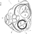
- the reference number 1 designates as a whole a heart valve prosthesis according to various embodiments.
- the heart valve prosthesis 1 includes a first portion 2 and a second portion 4 in turn including a radially expandable annular member 6 and a prosthetic heart valve 8 anchored to the radially expandable member.
- the first portion 2 takes the form of a spire-like element 20 having a general circumferential development and having a first and a second free ends 21, 22 facing each other.
- the first portion 2 includes a plug member 23 (generally even more than one plug member, preferably two, maybe envisaged) provided on the spire-like element and orthogonal thereto (i.e. having an axis parallel to a main axis X1 of the spire-like element 20).
- the plug member 23 is formed integrally with the spire-like element 20.
- the spire-like element 23 is mechanically fastened to the spire-like element 20.
- the plug member 23 is located near a free end of the spire-like element 20, in the embodiment depicted in figure 1 the free end 21.
- the radially expandable member 6 includes in various embodiments a generally mesh-like or apertured structure (e.g. a stent-like structure) which allows significant radial deformations and therefore provides the radial expansion capability.
- a generally mesh-like or apertured structure e.g. a stent-like structure
- the expandable annular member 6 may consist of a stent member including a first mesh portion 60 integral with a second mesh portion 61. Both the mesh portions 60, 61 develop in a circumferential fashion but the first mesh portion 60 extends essentially in the radial direction (and possibly, in some embodiments, also in an axial direction so to have a general flared configuration) so to protrude radially with respect to the mesh portion 61, while the second mesh portion 61 is generally cylindrical in shape and therefore extends substantially in an axial direction.
- the mesh portion 60, 61 which make up the stent member 6 may be made of a shape memory material such as Nitinol.
- the stent member 6, in particular the mesh portion 60 furthermore includes a socket 62 which is configured to receive the plug member 23 and generally takes the shape of a cylindrical hollow member having one or more retention formations on the interior surface which are configured to cooperate with corresponding retention formations to provide a firm anchoring of the plug member 23.
- the plug member 23 may include circumferential ribs 230 which have a generally conical surface with a slope that converges towards the free end of the plug member 23.
- the socket 62 may include complementary circumferential ribs 620 which have a generally conical surface with a slope oriented so to face the slope of the ribs 230 so to allow a movement of the plug 23 relative to the socket 62 only when the former is inserted into the latter and only in the direction of insertion, at least in part similar to the operation of a ratchet-and-pawl mechanism.
- the socket member in various embodiments may be configured to allow the movement of said plug member only in the direction of insertion so to avoid the separation of the second portion from the first portion once the prosthesis has been implanted. This may be achieved by a number of unidirectional coupling.
- the socket 62 is permanently coupled to the stent member 6, and in some embodiments it may be mechanically connected thereto (for example by means of a small rivet). In other embodiments the socket 62 may even be made integral with the stent member 6 for example by means of soldering thereto.
- the heart valve prosthesis is in various embodiments a prosthesis of the "biological" type. It is, in other words, a prosthesis which is sized and dimensioned and shaped in order to replicate both the structure and the behaviour of natural heart valves (i.e. provided with tissue-like coapting valve leaflets) and is made in a large majority of embodiments of biological tissue or even artificial material such as biocompatible polymers.
- the prosthetic heart valve 8 includes a sewing ring SR and a number of leaflets VL which is generally comprised between 2 and 4 leaflets.
- the prosthetic heart valve 8 includes, as an example, four leaflets VL, but the skilled man will appreciate that the number of leaflets will vary depending on the specific needs.
- the prosthetic heart valve 8 is anchored to the expandable portion 6 for example by means of stitching. In other embodiments, specific adhesives may be used in alternative or in conjunction with the stitches. Furthermore, in some embodiments the prosthetic valve 8 may be anchored to the stent member 6 also by means of specifically designed, radially protruding fingers provided either on the mesh portion 60 or on the mesh portion 61 (or both) and configured to settle in the commissures of the prosthetic valve 8. Stitches may be passed through the commissures and the fingers so to firmly anchor the prosthetic valve 8 to the meshed structure 6.
- FIG. 2 to 5 an exemplary implantation sequence of the heart valve prostheses according to various embodiments herein described is shown.
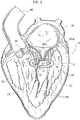
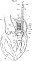
- FIG. 2 A first stage of the sequence is shown in figure 2 , wherein a human heart H is represented in sectional view across the left ventricle and the left atrium. This means that in figures 2 to 5 , as a non-limiting example, a mitral valve replacement procedure is shown.
- the implantation of the heart valve prosthesis 1 may be performed both with traditional surgical techniques or with the aid of the delivery catheters similar to those used in minimally invasive implantation procedures.
- the practitioner may deliver the first portion 2 in the left ventricle LV with the spire-like element 20 collapsed to a smaller diameter with respect to its nominal (i.e. unconstrained) one. Thanks to the collapsed spire-like elements 20, the latter may be routed through the native valve leaflets NVL of the mitral valve then let to expand in the left ventricle.
- the first portion 2 is configured to be implanted in the ventricle (it may be said that the portion 2 is a "ventricular" portion of the prosthesis 1) and it is configured to enclose a plurality of native chordae tendineae in the left ventricle and the native valve leaflets NVL to which said chordae tendineae are connected.
- the verb " to enclose” as used herein is intended to designate a situation in which the chordae tendineae and the native valve leaflets are contained within the portion 2, namely the spire-like member 20.
- the practitioner may first let the chordae tendineae CT into the spire-like element 20 by leading them across the gap between the free ends 21, 22 (a further dilation of the spire-like element may also be envisaged if necessary). Then, the practitioner may encircle the chordae tendineae with the spire-like element 20 by using the plug member 23 as a sort of "pivot member" for controlling a rotation of the spire-like element 20 around the native chordae tendineae CT. The rotation may therefore be controlled around the axis of the plug element 23.
- the spire-like element 20 may be positioned both by means of a grasper or a similarly designed clamp or by means of a dedicated delivery system.
- a delivery system not shown herein in detail, may comprise a hub whereon the spire-like element is retained in a collapsed configuration thanks to a slidable cap or sheath which is further configured to be displaced in order to allow the radial expansion of the spire-like element 20.
- a recall member may be provided, for example a guidewire, in order to have the possibility of displacing the spire-like element within the ventricle. If instead a grasper is used, the grasper itself may serve to displace the member 20.
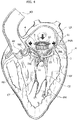
- the implantation procedure goes on with a step depicted in figure 3 , wherein the spire-like element 20, already enclosing and encircling the native chordae tendineae CT, is displaced towards the native valve annulus NVA by means of either the recall member (e.g. a guidewire) or the grasper.
- the recall member e.g. a guidewire
- both the chordae tendineae and the native mitral valve leaflets NVL are enclosed within the spire-like element 20, with the plug member 23 conveniently positioned with respect to the annulus so as to protrude through the commissures between the native valve leaflets NVL once the spire-like element has been brought in contact with the mitral valve annulus MVA.
- the plug member may be sized and dimensioned in order to have a blunt free end in order to avoid possible damages to the surrounding tissue.
- the plug member 23 may be sized and dimensioned so to have a sharp free end (for example like a sting) thereby allowing for a piercing of the tissue of native valve leaflets.
- the design of the radially expandable portion 6 as well as the spire-like element 20 may be more feasible as the plug member 23 is not limited to be positioned between the commissures of the native valve leaflets but it may positioned at a location that ensures at the same time a firm anchoring of the spire-like element to the implantation site (for example a portion of the native valve annulus whereat the amount of the surrounding tissue is higher with respect to other locations) and a more effective positioning of the prosthetic valve 8 with respect to the expandable portion 6.
- the delivery system configured for use with the second portion 4 may be comprised of a hub which acts as a locking member for the collapsed stent member 6 and prosthetic valve 8 and a slidable sheet which retains the stent member 6 and the prosthetic valve 8 in the collapsed condition and that can be further displaced in an axial direction in order to release the collapsed portion 4 and let the stent member 6 to expand radially.
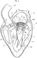
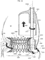
- the whole second portion 4 is delivered at the mitral valve annulus ( figure 4 ), as it is configured to be implanted and coupled to the first portion 2 at the native valve annulus itself.
- the stent member 6 is made to expand at the native valve annulus so to trap the native valve leaflets (as well as the chordae tendineae) between itself and the spire-like element 20, as shown in figure 5 .
- the stent member 6 also a portion of the chordae tendineae CT which are enclosed within the spire-like element 20 are trapped between the latter and the stent member 6.
- the socket 62 is made to fit onto the plug member 23 which protrudes from the ventricle (either through the tissue surrounding the native valve annulus or through the commissures of the native valve leaflets, as described) so to firmly couple the second portion 4 to the first portion 2.
- FIG. 5 The final stage of the implantation procedure is shown in figure 5 , wherein the whole second portion 4 is coupled to the first portion 2 which encircles and encloses a plurality of the native chordae tendineae CT in the left ventricle LV and the native valve leaflets NVL connected to the chordae tendineae CT.
- Perivalvular leakage is reduced to a negligible amount thanks to the sealing action provided by the entrapment of the native valve leaflets between the sent member 6 and the spire-like element 20. Furthermore, unlike a traditional valve replacement procedure, the native chordae tendineae CT and the native valve leaflets NVL are maintained, so that a higher life expectancy and a lower morbidity with respect to traditional valve replacement procedures can be achieved.
- the heart valve prosthesis 1 combines both of the advantages of a replacement intervention and a repair intervention, in that after the implantation of the prosthesis 1 the patient may take benefit from a, so to say, "brand new” and specifically engineered heart valve while also retaining the native chordae tendineae, the native valve leaflets the papillary muscle and whatever populates the interior of the left ventricle.
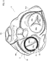
- a top view of the human heart taken from the aorta shows the four cardiac valves in a substantially plan view.
- the four valves are labelled with the references MV for the mitral valve, TCV for the tricuspid valve, AV for the aortic valve and PV for the pulmonary valve.
- the heart valve prosthesis may be used wherever a native valve is located at an interface between a ventricle and an atrium of the human heart. This means in other words that the prosthesis 1 may be suitable both for replacing the mitral valve, as shown in figure 6 , and for replacing the tricuspid valve as shown in figure 7 .
- Figures 6 and 7 both show the position of the spire-like element 20 relative to the native valve annulus in the case of the replacement of the mitral valve ( figure 6 ) and tricuspid valve ( figure 7 ).
- a spire-like element 20 is represented with a solid black line superimposed to the native heart valve in the top view of the human heart, but the skilled man will readily appreciate, in view of the foregoing disclosure, that the spire-like element 20 is positioned below the valve annulus and that the representation given in figures 6 and 7 is purely schematic and it is intended to facilitate the understanding of the disclosure.
- the plug member 23 is located in corresponding of a commissure of the native valves (either mitral or tricuspid), as the gap between the free ends 20, 21 is located substantially in a region corresponding to the commissures themselves.
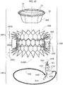
- FIGS 8 and 9 show examples of the heart valve prosthesis 1 wherein the plug member 23 is configured for piercing the tissue surrounding the native annulus and/or the native valve leaflets.
- the location at which the plug 23 pierces the native annulus and/or the native valve leaflets is chosen so to intercept a region wherein the amount of tissue is such as ensure on one side a firm anchoring of the prosthesis 1 to the implantation site and on the other side a minimum impact on the heart.
- the radius R6 is chosen as a function of the geometry of the native valve annulus, also taking into account the presence of the native valve leaflets. It can therefore be assumed as a reference dimension according to which the other dimensions of the stent member 6 may be chosen.
- the ratio W60/R6 is chosen in the range between 0.1 and 0.2.
- the ratio L61/R6 is chosen in the range 0.7 to 1.
- the radius R200 is generally chosen so as to encircle both the chordae tendineae CT and the native valve leaflets NVL and it is generally sized and dimensioned to be greater than the radius R6 in the expanded configuration of the stent member 6.
- R200 can be assumed, similarly to R6, as a reference dimension according to which the remaining dimensions of the spire-like member 20 may be chosen.
- the ratio R201/R200 is chosen in the range 1.1 to 1.2.
- the variation of the ratio R201/R200 may entail a corresponding variation in the circumferential flexibility of the spire like member 20: however, the choice thereof in the range indicated above essentially results in minor variations of the flexibility, which is instead preferably modulated by adding circumferential stiffening ribs or the like (preferably in embodiments wherein a sole plug member 23 is provided).
- the ratio R201/R200 is preferably kept within the above range essentially to privilege easy handling of the spire like member 20 when encircling the chordae tendineae: much higher values of the ratio R201/R200 may in fact result in an undesirable reduction of the available room for encircling the chordae tendineae.
- the angle ⁇ 20 is similarly chosen on the basis of the anatomy of the patient, primarily the chordae tendineae, again to privilege handling and comfort when encircling the latter. It is generally comprised in the range 30° to 40°.
- the entire stent member 6 may be covered with a biocompatible fabric or sheath (for example coated with biocompatible carbon) which enhances both the biocompatibility of the prostheses and the minimization of the perivalvular leakage.
- a biocompatible fabric or sheath for example coated with biocompatible carbon
- the spire-like element 20 may be made of metal material, as well as the plug 23, while in other embodiments a polymeric material may be chosen.
- a biocompatible coating e.g. pyrolitic carbon
- pyrolitic carbon may be applied on the surface of the spire-like element 20 in order to enhance the compatibility with the blood.
- the same snap fit action that characterizes the plug member 23 with the circumferential ribs 20 and the socket 62 with the circumferential ribs 620 may be achieved otherwise, for example by shaping the plug member 23 as a dowel.
- at least one further plug member (as well as a corresponding socket member) may be provided in the first portion 2 (as well as second portion 4 for the socket) in order to further enhance and improve the coupling between the first and second portions 2, 4.
- further plug members may be located in a position substantially diametrically opposite that of the first plug member, and in certain embodiments yet a further plug may be located in correspondence of the posterior leaflet of the mitral valve.
- the heart valve prosthesis 1000 includes a first portion 1002 and a second portion 1004 in turn including a radially expandable annular member 1006 and a prosthetic heart valve 1008 anchored to the radially expandable annular member.
- the first portion 1002 includes a deployable spire-like element 1020, herein shown deployed and protruding from a proximal portion of a deployment instrument sized and dimensioned so as to define a plug member 1023.
- the spire like element 1020 may be embodied as a thermo-formed wire which is capable of recovering a substantially annular pattern from any shape that may be imparted thereto.
- the plug member 1023 is embodied as an L-shaped tubular member having circular cross section and including, at one end thereof, a threaded portion 1021 (preferably with internal thread). On a stretch of the plug member 1023 adjacent the threaded portion 1021 one or more circumferential ribs 1230 are provided. Additionally, a through hole 1024 is provided essentially in correspondence of a knee of the plug member 1023.
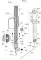
- the plug member 1023 is part of a deployment instrument depicted in figure 10A and designated as a whole by the reference 2000.
- the deployment instrument 2000 includes a proximal portion depicted in figure 11A and a distal portion depicted in figure 11B .
- proximal and distal refer to the implantation site.
- the proximal portion includes the plug member 1023, which defines i.a. a proximal tip of the deployment instrument 2000, and a shaft 2002 connected to the plug member 1023.
- the distal portion ( figure 11B ), on the other hand, includes a manipulation assembly 2004 including a grip 2006 and one or more actuator members.
- the shaft 2002 is releasably connected to the plug member 1023.
- Such releasable connection is in some embodiments - such as those depicted in figure 11 - attained by means of a threaded end portion 2008, preferably having an external thread, which is configured to mate with the (internally) threaded portion 1021 of the plug member 1023.
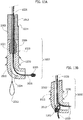
- the shaft 2002 in various embodiments takes the form of a tubular member (having therefore a hollow section) which houses the spire-like member 1020 in an extended (i.e. linear) configuration together with a wire-like member 2010.
- the spire-like member 1020 is provided with an ogive-like member 1200 at a free end thereof, while the wire-like member 2010 terminates with a loop 2012.
- FIG 11A in an undeployed state, i.e.
- the ogive-like member 1200 may protrude outside of an end of the plug member 1023 opposite that where the threaded portion 1021 is located, whilst the wire-like member is arranged so that the loop 2012 comes out of the opening 1024.
- the spire like member 1020 is further provided with a weakened section 1026, better visible in the enlarged view of figure 11A (see the circle on the left).
- the weakened section 1026 has in one embodiment a reduced cross section, while in another embodiment it may include indentations, notches or other kind of carving in order to locally amplify the tensile stress.
- a major portion of the length of the shaft 2002 has furthermore a substantially D-shaped cross section, thereby exhibithing a flattened side surface 2013. Only a minor share of the length of the shaft 2002, located in the vicinity of the threaded portion 2008 exhibits a full circular cross section, defining thereby an abutment shoulder 2014 at which the flattened side surface (2013) terminates.
- a sheath 2015 is slidably mounted on the shaft 2002 and particularly on the flattened side surface 2013.
- the sheath 2015 is mounted off-center with respect to the shaft 2002, i.e. a central axis thereof (which may not be a symmetry axis, as in the embodiment depicted in figure 11 ), is offset (and parallel) with respect to a longitudinal axis X2002 of the shaft 2002.
- the slidable coupling between the sheath 2015 and the shaft 2002 may be achieved by means of a hub 2016, preferably an integral portion of the sheath 2015, which exhibits a D-shaped cavity matching the shape of the portion of the shaft 2002 whereon the flattened side surface 2013 is provided.
- the abutment shoulder 2014 defines in such embodiments essentially an axial stop element, as the hub 2016, once come into contact with the abutment shoulder 2014, would prevent the sheath 2015 from a further axial movement toward the proximal end of the instrument 2000 due to the change in shape (and the increase) of the cross section of the shaft 2002.
- the distal portion of the instrument 2000 includes a number of actuators, in this specific embodiment in the number of three, each coupled to a specific element of the instrument 2000.
- the manipulation assembly 2004 includes a first actuator 2018 operatively connected to the sheath 2015, a second actuator 2020 operatively connected to the spire like member 1020 and a third actuator 2022 operatively connected to the wire-like member 2010.
- each actuator may be embodied as either a linear-motion or a rotary-motion actuator.
- the former choice may be more suitable for fast-acting mechanisms (i.e. with higher transmission ratios), while the latter may be more suitable for slow-acting mechanisms (i.e. with lower transmission ratios).
- the actuators 2018 and 2020 are of the rotary-motion type, while the actuator 2022 is of the linear motion type, as also indicated by the corresponding solid arrows.
- the radially expandable member 1006 includes a generally mesh-like or apertured structure (e.g. a stent-like structure) which allows significant radial deformations and therefore provides the radial expansion capability.
- a generally mesh-like or apertured structure e.g. a stent-like structure
- the expandable annular member 1006 consists therefore of a stent member including a first mesh portion 1060A, of a generally cylindrical shape, integral with a second and third mesh portions 1060B, 1060C located at opposite ends thereof, both having a flared pattern when radially unconstrained.
- Each of the mesh portions 1060A, 1060B, 1060C develops in a circumferential fashion but when deployed the second and third mesh portions 1060B, 1060C extend essentially in the radial direction (and to a minor extent also in the axial direction due to the generally flared configuration) so to protrude radially with respect to the first mesh portion 1060A, which instead is generally cylindrical in shape and therefore extends substantially in an axial direction.
- the mesh portions 1060A, 1060B, 1060C may be made of a shape memory material such as Nitinol.
- a socket 1062 which is configured to receive the plug member 1023 is fixed to the stent member 1006, particularly to the mesh portion 1060A.
- the socket 1062 may generally take the shape of a cylindrical hollow member having one or more retention formations on the interior surface which are configured to cooperate with corresponding retention formations on the plug member 1023 to provide a firm anchoring to the plug member itself.
- the plug member 1023 may include - as retention formations - circumferential ribs 1230 which have a generally conical surface with a slope that converges towards the free end of the plug member 1023 (i.e. the threaded portion 1021).
- the socket 1062 may include complementary circumferential ribs 1620 which have a generally conical surface with a slope oriented so to face the slope of the ribs 1230, thereby allowing a movement of the plug member 1023 relative to the socket 1062 only when the former is inserted into the latter and only in the direction of insertion, at least in part similar to the operation of a ratchet-and-pawl mechanism.
- the socket member in various embodiments may be configured to allow the movement of said plug member only in the direction of insertion so to avoid the separation of the second portion from the first portion once the prosthesis has been implanted. This may be achieved by a number of unidirectional couplings.
- the socket 1062 is permanently coupled to mesh portion 1060A, for example by soldering thereto.
- the heart valve prosthesis 1008 is in various embodiments completely identical to the heart valve prosthesis 8, therefore the description already provided in respect thereof still applies.
- the prosthetic heart valve 1008 includes a sewing ring SR and a number of leaflets VL which is generally comprised between two and four leaflets.
- the prosthetic heart valve 1008 includes, as an example, four leaflets VL, but the skilled man will appreciate that the number of leaflets will vary depending on the specific needs.
- the prosthetic heart valve 1008 is anchored to the expandable member 1006 for example by means of stitching. In other embodiments, specific adhesives may be used in alternative or in conjunction with the stitches. Furthermore, in some embodiments the prosthetic valve 1008 may be anchored to the stent member 1006 also by means of specifically designed, radially protruding fingers provided either on the mesh portion 1060A or on the mesh portion 1060B (or both) and configured to settle in the commissures of the prosthetic valve 1008.
- Stitches may be passed through the commissures and the fingers so to firmly anchor the prosthetic valve 1008 to the mesh structure.
- an exemplary implantation sequence of the heart valve prosthesis 1000 will be detailed in the following.
- a mitral valve replacement has been chosen, but the same may be applied to the tricuspid valve.
- second portion 1004 is mounted on the instrument 2000 as shown in figure 15 : the expandable annular member (stent member) 1006 with the prosthetic heart valve 1008 firmly anchored thereto is held radially collapsed into the sheath 2015 which unlike the view of figure 15 (which shows an advanced stage of the implantation sequence), is held at a distance from the abutment shoulder 2014.
- the socket member 1062 is slidably mounted onto the shaft 2002 so that also the ensemble of the expandable member 1006 and the valve 1008 is located off-center with respect to the longitudinal axis X2002. Additionally, in various embodiments the hub 2016 is sized and dimensioned so to be axially in contact with the socket member 1062.
- the inner diameter of the socket 1062 even in correspondence of ribs 1620 (which protrude radially inwardly) shall be greater than the maximum diameter or anyway transversal dimension of the shaft 2002 in order to allow for an unimpeded sliding over the entire length of the shaft, for reasons which will appear more evident in the following.
- the instrument 2000 is introduced into the left atrium via an atrial access point AAP.
- the proximal end of the instrument is advanced towards the native mitral valve MV.
- the proximal end is then advanced across the mitral valve between the two native valve leaflets NVL and into the left ventricle LV. Shortly afterwards, it is further displaced radially in a peripheral position with respect to the mitral valve MV.
- the advancement of the instrument 2000 into the left ventricle is stopped when the end of the plug member 1023 wherefrom the undeployed spire-like member 1020 protrudes reaches a position relative to the chordae tendineae CT which in various embodiments may be substantially halfway between the native valve leaflets NVL and the papillary muscles PM.
- An enlarged view of the proximal end of the instrument at this stage of the implantation procedure is shown in figure 13A .
- the spire-like member 1020 is then deployed from the proximal end of the instrument 2000 by acting on the actuator 2020. Thanks to the thermo-forming of the spire-like member 1020, when deployed it immediately recovers a circular pattern, so to enable the practitioner to encircle the chordae tendineae CT by the member 1020 itself. See in this respect the sequence of solid arrows in figure 12 located along the member 1020.
- the deployment of the spire-like member 1020 is continued until all the chordae tendineae CT are essentially encircled and until the ogive-like member 1200 meets the loop 2012 of the wire-like member 2010.
- the loop 2012 is configured to intercept the free end of the spire-like member 1020 in the deployed configuration, particularly the ogive-like member 1200.
- the practitioner may pull the wire-like member 2010 by acting on the actuator 2022 and draw the ogive-like member 1200 and a portion of the spire like member 1020 immediately adjacent thereto into the opening 1024.
- the result of this operation is shown in figure 13B .
- the opening 1024 and the ogive-like member 1200 shall be sized and dimensioned so that when the latter is drawn into the opening 1024 bent back onto the spire-like member 1020, the total transversal dimension produces a sort of force-fit engagement with the opening 1024 itself. In this way, an essentially closed loop may be created from the spire-like member 1020.
- the practitioner may exert a further pulling action on the wire-like member 2010, so to cause a failure of the loop which thus breaks open thereby allowing the practitioner to remove the wire-like member 2010 from the instrument 2000.
- a further pulling action may be exerted on the spire like member 1020 by the actuator 2020 so to cause a failure of the weakened section 1026.
- the portion of the member 1020 upstream the plug member 1023 can therefore be removed from the instrument 2000.
- the weakened section 1026 is positioned so that when the spire like member is fully deployed around the chordae tendineae and force fitted into the opening 1024, it is located just below the end of the threaded portion 1021.
- the entire instrument 2000 is first raised back up towards the left atrium LA, thereby bringing the closed loop created by the member 1020 into contact with the native valve leaflets NVL (while maintaining the chordae tendineae encircled therein).
- the plug member 1023 is now positioned across the mitral valve, with a portion abutting either the native valve annulus or the native valve leaflets from the ventricle and another portion (i.e. that carrying the circumferential ribs 1230) protruding into the atrium.
- the sheath 2015 with the stent member 1006 and the valve 1008 is advanced towards the mitral valve MV: the D-shaped section of the hub 2016 and the shaft 2002 prevents any undesired rotation between the sheath (and the prosthesis held therein) and the shaft, so that no misalignments of the prosthesis may occur.
- the socket 1062 attached to the stent member 1006 simply slides down the shaft together with the prosthesis drawn and pushed by the hub 2016.
- the final position of the portion 1004, as well as the sheath 2015, is illustrated in figure 15 .
- the sheath 2015 is advanced until an engagement is reached of the plug member 1023 and the socket 1062.
- the engagement is of the snap-fit type due to the presence of the circumferential ribs 1230 and 1620.
- the slopes of each circumferential rib on the plug and the socket member are oriented so to allow a relative movement between the former and the latter only in the direction of engagement thereof, thereby preventing any undesired disengagement in a way at least roughly similar to a ratchet and pawl mechanism.
- the socket member 1062 can be driven into engagement with the plug member by acting on the sheath 2015, i.e. by displacing the latter in a proximal direction towards the plug member 1023: the same action will be imparted to the hub 2016 and transferred to the socket member 1062 thanks to the contact therebetween.
- the socket member 1062 is capable of sliding past the abutment shoulder 2014, the hub is impeded for the reasons explained in the foregoing.
- the abutment shoulder therefore acts as an axial stop member, preventing the sheath 2015 from travelling too far down the shaft 2002, thereby avoiding damages to the prosthesis, the surrounding tissues and the patient.
- the sheath may be retracted distally away from the implantation site so to allow a radial expansion of the stent member 1006.
- the expansion capabilities of the stent member 1006 may be such that no post-expansion is needed. In other embodiments, the expansion capabilities may be chosen so that a post expansion through a balloon (not shown) may be necessary.
- the mesh portions 1060B and 1060C regain a flared pattern so to further enhance the anchoring of the prosthesis above and below the valve annulus.
- the practitioner may separate the instrument 2000 from the proximal portion thereof, i.e. from the plug member 1023, simply by unscrewing the shaft 2002 from the plug member 1023. Equivalently, in embodiments wherein other connections than a threaded one are envisaged, the practitioner may act upon the connection so as to release the coupling.
- the plug member 1023 therefore remains at the implantation site as part of the prosthesis 1000.
- the instrument 2000 is at the same time operable to deliver and deploy the prosthesis at the implantation site and configured so to provide also a portion of the prosthesis 1000 itself (i.e. the plug member 1023).
- a first portion 1002 of the prosthesis includes a telescopic spire-like member 1020' including, in the embodiment specifically illustrated herein, three telescoped segments 1020A, 1020B, 1020C. As visible in figure 18 , in an undeployed condition the telescoped segment 1020A already protrudes with respect to the plug member 1023 and is in abutment against an annular flange 1023F' of the plug member 1023.
- An inflatable balloon BL is housed deflated and axially compressed inside the shaft 2002 and the plug member 1023, and it is fixed at one end to the segment 1020C, which is the smallest in diameter.
- the telescopic spire-like member 1020' is deployed by inflating the balloon BL, for example by relying upon the lumen provided inside the shaft 2002 and the plug member 1023 (both hollow, the latter with no opening 1024).
- the lumen provided inside the shaft 2002 and the plug member 1023 both hollow, the latter with no opening 1024.
Landscapes
- Health & Medical Sciences (AREA)
- Cardiology (AREA)
- Engineering & Computer Science (AREA)
- Biomedical Technology (AREA)
- Heart & Thoracic Surgery (AREA)
- Transplantation (AREA)
- Oral & Maxillofacial Surgery (AREA)
- Vascular Medicine (AREA)
- Life Sciences & Earth Sciences (AREA)
- Animal Behavior & Ethology (AREA)
- General Health & Medical Sciences (AREA)
- Public Health (AREA)
- Veterinary Medicine (AREA)
- Prostheses (AREA)
Claims (11)
- Kombination einer Herzklappenprothese und eines Instruments zum Implantieren von dieser, wobei die Herzklappenprothese (1;1000) ausgebildet ist, an einem Herzklappenring, welcher an einer Übergangsstelle zwischen einer Herzkammer (LV) und einem Vorhof (LA) angeordnet ist, implantiert zu werden, wobei die Herzklappenprothese (1; 1000) umfasst:- einen ersten Abschnitt (2; 1002), der ausgebildet ist, eine Mehrzahl von Klappenhaltefäden (CT) in der Herzkammer (LV) und native Klappensegel (NVL), mit denen die Klappenhaltefäden (CT) verbunden sind, zu umschließen, und- ein zweiter Abschnitt (4; 1004) mit einem radial expandierbaren Ringelement (6; 1006) und einer prothetischen Herzklappe (8; 1008), die an dem radial expandierbaren Ringelement (6; 1006) verankert ist, wobei das radial expandierbare Ringelement (6; 1006) des zweiten Abschnitts (4; 1004) ein Stent-Element ist,wobei der erste Abschnitt (2; 1002) ausgebildet ist, in die Herzkammer (LV) implantiert zu werden, und
wobei der zweite Abschnitt (4; 1004) ausgebildet ist, an dem Herzklappenelement implantiert und mit dem ersten Abschnitt (2; 1002) gekoppelt zu werden,
wobei der zweite Abschnitt (4; 1004) ausgebildet ist, mit dem ersten Abschnitt (2; 1002) in der Art eines Schnappverschlusses gekoppelt zu werden, wobei der erste Abschnitt (2; 1002) ein spitzenartiges Element (20; 1020) mit einem Steckerelement (23; 1023), welches ausgebildet ist, mit einer Buchse (62; 1062) an dem zweiten Abschnitt (4; 1004) gekoppelt zu werden, um eine Kopplung des ersten Abschnitts (2; 1002) zu dem zweiten Abschnitt (4; 1004) in der Art eines Schnappverschlusses vorzusehen, umfasst,
wobei das Instrument zum Implantieren der Herzklappenprothese umfasst;- eine proximale Spitze;- einen Schaft (2002),- eine Hülle (2015), welche gleitend entlang des Schafts (2002) angebracht ist und ausgebildet ist, das Stent- Element (1006) des zweiten Abschnitts (1004) in einem radial kollabierten Zustand zu halten,- eine Manipulationseinheit (2004),wobei das Steckerelement die proximale Spitze (1023) definiert,
wobei der Schaft (2002) lösbar mit dem Steckerelement (1023) gekoppelt ist, und
wobei der zweite Abschnitt (1004) innerhalb der Hülle (2015) angebracht ist, so dass das Buchsenelement (1062) ebenfalls gleitend auf dem Schaft (2002) angebracht ist. - Die Kombination einer Herzklappenprothese und eines Instruments zum Implantieren von dieser nach Anspruch 1, dadurch gekennzeichnet, dass das Stent-Element einen ersten Netzabschnitt (1060A) und einen zweiten und einen dritten Netzabschnitt (1060B, 1060C) an gegenüberliegenden Enden des ersten Netzabschnitts (1060A) aufweist, wobei der erste Netzabschnitt (1060A) eine im Wesentlichen zylindrische Form und der zweite und dritte Netzabschnitt (1060B, 1060C) eine aufgebördelte Struktur aufweisen.
- Die Kombination einer Herzklappenprothese und eines Instruments zum Implantieren von dieser nach Anspruch 2, dadurch gekennzeichnet, dass das Buchsenelement (1062) an dem ersten Netzabschnitt (1060A) fixiert ist.
- Die Kombination einer Herzklappenprothese und eines Instruments zum Implantieren von dieser nach Anspruch 1, dadurch gekennzeichnet, dass der Schaft (2013) einen Abschnitt mit einem D- förmigen Querschnitt aufweist und eine abgeflachte Seitenoberfläche (2013) besitzt, wobei die abgeflachte Seitenoberfläche an einer Anschlagschulter (2014) endet, wobei die Hülle eine Nabe (2016) umfasst, durch welche die gleitende Kopplung mit dem Schaft erreicht wird und welche eineülle eine Narbe (2016), mittels derer die gleitende Kopplung mit dem Schaft dicht wird und welche eine D- förmige Kavität passend zu dem D- förmigen Querschnitt des Abschnitts des Schafts (2002) besitzt.
- Die Kombination einer Herzklappenprothese und eines Instruments zum Implantieren von dieser nach Anspruch 4, dadurch gekennzeichnet, dass die Nabe (2016) an dem Buchsenelement anliegt, wenn das Stent-Element (1006) des zweiten Abschnitts (1004) innerhalb der Hülle (2015) gehalten ist.
- Die Kombination einer Herzklappenprothese und eines Instruments zum Implantieren von dieser nach Anspruch 5, dadurch gekennzeichnet, dass das Buchsenelement (1062) ausgebildet ist, mit dem Steckerelment (1023) mittels Verschiebung der Hülle (2015) in eine proximale Richtung entlang des Schafts (2002) während des Implantierens in Eingriff getrieben zu werden.
- Die Kombination einer Herzklappenprothese und eines Instruments zum Implantieren von dieser nach einem der Ansprüche 1 und 4 bis 6, dadurch gekennzeichnet, dass das spitzenartige Element (1020) einen ausfahrbaren, thermo- geformten Draht (1020) umfasst, welcher innerhalb des Schafts (2002) und des Steckerelements (1023) in einer linearen Konfiguration untergebracht ist und von dem Steckerelement (1023) an dessen einem Ende vorragt, wobei das Instrument (2000) ferner ein drahtförmiges Element (2010), welches ebenfalls innerhalb des Schafts (2002) untergebracht ist und aus dem Steckerelement (1023) herauskommt, wobei das drahtförmige Element (2010) in einer Schleife (2012) endet, welche ausgebildet ist, ein freies Ende (1200) des spitzenartigen Elements (1020) einer ausgefahrenen Konfiguration abzuschneiden.
- Die Kombination einer Herzklappenprothese und eines Instruments zum Implantieren von dieser nach Anspruch 7, dadurch gekennzeichnet, dass das spitzenartige Element (1020) ein spitzbogenartiges Element (1200) am freien Ende aufweist, wobei die Schleife (2012) ausgebildet ist, das spitzbogenartige Element (1200) abzuschneiden, so dass das freie Ende des spitzenartigen Elements (1020), einschließlich des spitzenbogenartigen Elements (1200), in einen kraftschlüssigen Eingriff in eine Öffnung (1024) in das Steckerelement (1023) gezogen werden kann, wodurch das drahtförmige Element durch Ziehen des drahtförmigen Elements (2010) herauskommt.
- Die Kombination einer Herzklappenprothese und eines Instruments zum Implantieren von dieser nach Anspruch 1, dadurch gekennzeichnet, dass der erste Abschnitt (1002') ein teleskopförmiges spitzenartiges Element (1020'), welches aus einer Mehrzahl von Teleskopsegmenten (1020A, 1020B, 1020C), die ausgebildet sind, mittels eines aufblasbaren, deflatiert gehaltenen und axial zusammengedrückten Ballons (BL) innerhalb des Schafts (2002) und des Steckerelements (1023) ausgefahren zu werden.
- Die Kombination einer Herzklappenprothese und eines Instruments zum Implantieren von dieser nach Anspruch 1, dadurch gekennzeichnet, dass das Stent-Element (6) einen ersten Netzabschnitt (60) und einen zweiten Netzabschnitt (61) aufweist, wobei der erste Netzabschnitt (60) und der zweite Netzabschnitt (61) beide sich in eine Umfangsrichtung erstrecken und wobei der erste Netzabschnitt (60) sich ferner in eine radiale Richtung erstreckt, wobei der zweite Netzabschnitt (61) sich in eine axiale Richtung erstreckt, wobei das Buchsenelement (62) mit dem ersten Netzabschnitt (60) gekoppelt ist.
- Die Kombination einer Herzklappenprothese und eines Instruments zum Implantieren von dieser nach einem der Ansprüche 1 und 9 bis 10, dadurch gekennzeichnet, dass das spitzenartige Element (20) einen umlaufenden Aufbau mit einem ersten (21) und einem zweiten (22) freien Ende besitzt, wobei das Steckerelement (23) in der Nähe eines (21) der freien Enden (21, 22) angeordnet ist.
Priority Applications (3)
| Application Number | Priority Date | Filing Date | Title |
|---|---|---|---|
| EP13425113.1A EP2835112B1 (de) | 2013-08-08 | 2013-08-08 | Herzklappenprothese |
| US14/910,975 US10143550B2 (en) | 2013-08-08 | 2014-07-17 | Heart valve prosthesis |
| PCT/IB2014/063176 WO2015019217A1 (en) | 2013-08-08 | 2014-07-17 | Heart valve prosthesis |
Applications Claiming Priority (1)
| Application Number | Priority Date | Filing Date | Title |
|---|---|---|---|
| EP13425113.1A EP2835112B1 (de) | 2013-08-08 | 2013-08-08 | Herzklappenprothese |
Publications (2)
| Publication Number | Publication Date |
|---|---|
| EP2835112A1 EP2835112A1 (de) | 2015-02-11 |
| EP2835112B1 true EP2835112B1 (de) | 2021-01-27 |
Family
ID=49303935
Family Applications (1)
| Application Number | Title | Priority Date | Filing Date |
|---|---|---|---|
| EP13425113.1A Active EP2835112B1 (de) | 2013-08-08 | 2013-08-08 | Herzklappenprothese |
Country Status (3)
| Country | Link |
|---|---|
| US (1) | US10143550B2 (de) |
| EP (1) | EP2835112B1 (de) |
| WO (1) | WO2015019217A1 (de) |
Cited By (15)
| Publication number | Priority date | Publication date | Assignee | Title |
|---|---|---|---|---|
| US11311376B2 (en) | 2019-06-20 | 2022-04-26 | Neovase Tiara Inc. | Low profile prosthetic mitral valve |
| US11357622B2 (en) | 2016-01-29 | 2022-06-14 | Neovase Tiara Inc. | Prosthetic valve for avoiding obstruction of outflow |
| US11389294B2 (en) | 2012-05-30 | 2022-07-19 | Neovasc Tiara Inc. | Methods and apparatus for loading a prosthesis onto a delivery system |
| US11389291B2 (en) | 2013-04-04 | 2022-07-19 | Neovase Tiara Inc. | Methods and apparatus for delivering a prosthetic valve to a beating heart |
| US11413139B2 (en) | 2011-11-23 | 2022-08-16 | Neovasc Tiara Inc. | Sequentially deployed transcatheter mitral valve prosthesis |
| US11419720B2 (en) | 2010-05-05 | 2022-08-23 | Neovasc Tiara Inc. | Transcatheter mitral valve prosthesis |
| US11464631B2 (en) | 2016-11-21 | 2022-10-11 | Neovasc Tiara Inc. | Methods and systems for rapid retraction of a transcatheter heart valve delivery system |
| US11491006B2 (en) | 2019-04-10 | 2022-11-08 | Neovasc Tiara Inc. | Prosthetic valve with natural blood flow |
| US11497602B2 (en) | 2012-02-14 | 2022-11-15 | Neovasc Tiara Inc. | Methods and apparatus for engaging a valve prosthesis with tissue |
| US11602429B2 (en) | 2019-04-01 | 2023-03-14 | Neovasc Tiara Inc. | Controllably deployable prosthetic valve |
| US11737872B2 (en) | 2018-11-08 | 2023-08-29 | Neovasc Tiara Inc. | Ventricular deployment of a transcatheter mitral valve prosthesis |
| US11779742B2 (en) | 2019-05-20 | 2023-10-10 | Neovasc Tiara Inc. | Introducer with hemostasis mechanism |
| US11793640B2 (en) | 2017-08-25 | 2023-10-24 | Neovasc Tiara Inc. | Sequentially deployed transcatheter mitral valve prosthesis |
| US11998447B2 (en) | 2019-03-08 | 2024-06-04 | Neovasc Tiara Inc. | Retrievable prosthesis delivery system |
| US12109111B2 (en) | 2015-12-15 | 2024-10-08 | Neovasc Tiara Inc. | Transseptal delivery system |
Families Citing this family (46)
| Publication number | Priority date | Publication date | Assignee | Title |
|---|---|---|---|---|
| EP3708123A1 (de) | 2009-03-30 | 2020-09-16 | JC Medical, Inc. | Nahtlose herzklappenprothesen sowie vorrichtungen und verfahren zur einführung |
| CN107496054B (zh) | 2011-06-21 | 2020-03-03 | 托尔福公司 | 人工心脏瓣膜装置及相关系统和方法 |
| JP6151705B2 (ja) | 2011-10-19 | 2017-06-21 | トゥエルヴ, インコーポレイテッド | 心臓弁置換のためのデバイス、システムおよび方法 |
| US10016271B2 (en) | 2011-10-19 | 2018-07-10 | Twelve, Inc. | Prosthetic heart valve devices, prosthetic mitral valves and associated systems and methods |
| US9039757B2 (en) | 2011-10-19 | 2015-05-26 | Twelve, Inc. | Prosthetic heart valve devices, prosthetic mitral valves and associated systems and methods |
| US11202704B2 (en) | 2011-10-19 | 2021-12-21 | Twelve, Inc. | Prosthetic heart valve devices, prosthetic mitral valves and associated systems and methods |
| US9011515B2 (en) | 2012-04-19 | 2015-04-21 | Caisson Interventional, LLC | Heart valve assembly systems and methods |
| US9427315B2 (en) | 2012-04-19 | 2016-08-30 | Caisson Interventional, LLC | Valve replacement systems and methods |
| US11406497B2 (en) | 2013-03-14 | 2022-08-09 | Jc Medical, Inc. | Heart valve prosthesis |
| CA2905422A1 (en) | 2013-03-14 | 2014-10-02 | Cardiovantage Medical, Inc. | Embolic protection devices and methods of use |
| US11259923B2 (en) | 2013-03-14 | 2022-03-01 | Jc Medical, Inc. | Methods and devices for delivery of a prosthetic valve |
| US9421094B2 (en) | 2013-10-23 | 2016-08-23 | Caisson Interventional, LLC | Methods and systems for heart valve therapy |
| EP2921140A1 (de) * | 2014-03-18 | 2015-09-23 | St. Jude Medical, Cardiology Division, Inc. | Perkutane verankerung für eine prothetische aortenklappe |
| USRE49792E1 (en) | 2014-05-14 | 2024-01-09 | Corcym S.R.L. | Implant device and implantation kit |
| US9974647B2 (en) | 2014-06-12 | 2018-05-22 | Caisson Interventional, LLC | Two stage anchor and mitral valve assembly |
| US9750607B2 (en) | 2014-10-23 | 2017-09-05 | Caisson Interventional, LLC | Systems and methods for heart valve therapy |
| US9750605B2 (en) | 2014-10-23 | 2017-09-05 | Caisson Interventional, LLC | Systems and methods for heart valve therapy |
| JP2017538540A (ja) * | 2014-12-19 | 2017-12-28 | 杭州啓明医療器械有限公司Venus Medtech (Hangzhou), Inc. | 低侵襲性の鍔付き僧帽弁の置換術 |
| US10265166B2 (en) | 2015-12-30 | 2019-04-23 | Caisson Interventional, LLC | Systems and methods for heart valve therapy |
| FR3058631B1 (fr) * | 2016-11-14 | 2019-01-25 | Laboratoires Invalv | Implant de traitement d'une valve biologique |
| US10653523B2 (en) | 2017-01-19 | 2020-05-19 | 4C Medical Technologies, Inc. | Systems, methods and devices for delivery systems, methods and devices for implanting prosthetic heart valves |
| US10561495B2 (en) | 2017-01-24 | 2020-02-18 | 4C Medical Technologies, Inc. | Systems, methods and devices for two-step delivery and implantation of prosthetic heart valve |
| US12029647B2 (en) | 2017-03-07 | 2024-07-09 | 4C Medical Technologies, Inc. | Systems, methods and devices for prosthetic heart valve with single valve leaflet |
| US10702378B2 (en) | 2017-04-18 | 2020-07-07 | Twelve, Inc. | Prosthetic heart valve device and associated systems and methods |
| US10709591B2 (en) | 2017-06-06 | 2020-07-14 | Twelve, Inc. | Crimping device and method for loading stents and prosthetic heart valves |
| US12036113B2 (en) | 2017-06-14 | 2024-07-16 | 4C Medical Technologies, Inc. | Delivery of heart chamber prosthetic valve implant |
| US10729541B2 (en) | 2017-07-06 | 2020-08-04 | Twelve, Inc. | Prosthetic heart valve devices and associated systems and methods |
| US10786352B2 (en) | 2017-07-06 | 2020-09-29 | Twelve, Inc. | Prosthetic heart valve devices and associated systems and methods |
| US20210177596A1 (en) * | 2017-10-27 | 2021-06-17 | Medtentia International Ltd Oy | Annuloplasty implant |
| CN210582754U (zh) | 2018-01-07 | 2020-05-22 | 苏州杰成医疗科技有限公司 | 用于输送瓣膜假体的输送系统 |
| CN210697902U (zh) | 2018-01-07 | 2020-06-09 | 苏州杰成医疗科技有限公司 | 心脏瓣膜假体 |
| US11857441B2 (en) | 2018-09-04 | 2024-01-02 | 4C Medical Technologies, Inc. | Stent loading device |
| US10912644B2 (en) | 2018-10-05 | 2021-02-09 | Shifamed Holdings, Llc | Prosthetic cardiac valve devices, systems, and methods |
| US12544226B2 (en) | 2019-02-14 | 2026-02-10 | 4C Medical Technologies, Inc. | Hydrophilic skirt for paravalvular leak mitigation and fit and apposition optimization for prosthetic heart valve implants |
| US11452628B2 (en) | 2019-04-15 | 2022-09-27 | 4C Medical Technologies, Inc. | Loading systems for collapsible prosthetic heart valve devices and methods thereof |
| US12186188B2 (en) | 2019-05-01 | 2025-01-07 | Twelve, Inc. | Support devices for transcatheter delivery system handles |
| US11452599B2 (en) | 2019-05-02 | 2022-09-27 | Twelve, Inc. | Fluid diversion devices for hydraulic delivery systems and associated methods |
| US12133797B2 (en) | 2020-01-31 | 2024-11-05 | 4C Medical Technologies, Inc. | Prosthetic heart valve delivery system: paddle attachment feature |
| US11931253B2 (en) | 2020-01-31 | 2024-03-19 | 4C Medical Technologies, Inc. | Prosthetic heart valve delivery system: ball-slide attachment |
| US12053375B2 (en) | 2020-03-05 | 2024-08-06 | 4C Medical Technologies, Inc. | Prosthetic mitral valve with improved atrial and/or annular apposition and paravalvular leakage mitigation |
| US11992403B2 (en) | 2020-03-06 | 2024-05-28 | 4C Medical Technologies, Inc. | Devices, systems and methods for improving recapture of prosthetic heart valve device with stent frame having valve support with inwardly stent cells |
| CA3163212C (en) * | 2020-03-09 | 2022-11-08 | Vesalius Cardiovascular Inc. | Apparatus and methods for clamping a mitral valve |
| CN111759540B (zh) * | 2020-07-15 | 2022-03-25 | 上海理工大学 | 一种瓣膜支架以及介入式心脏假体瓣膜 |
| US12594164B1 (en) | 2022-09-01 | 2026-04-07 | 4C Medical Technologies, Inc. | Prosthetic heart valve for natural blood flow |
| CN115462819B (zh) * | 2022-09-29 | 2025-07-25 | 中国医学科学院阜外医院 | 一种术前ct评估的双锚定多平面测量方法、应用 |
| US20240366366A1 (en) | 2023-03-24 | 2024-11-07 | 4C Medical Technologies, Inc. | Implant delivery |
Family Cites Families (97)
| Publication number | Priority date | Publication date | Assignee | Title |
|---|---|---|---|---|
| IT1159433B (it) | 1983-07-25 | 1987-02-25 | Sorin Biomedica Spa | Procedimento ed apparecchiatura per la fabbricazione di lembi valvolari per protesi valvolari cardiache e protesi valvolare cardiaca provvista di tali lembi |
| IT1208326B (it) | 1984-03-16 | 1989-06-12 | Sorin Biomedica Spa | Protesi valvolare cardiaca provvista di lembi valvolari di tessuto biologico |
| IT1245750B (it) | 1991-05-24 | 1994-10-14 | Sorin Biomedica Emodialisi S R | Protesi valvolare cardiaca, particolarmente per sostituzione della valvola aortica |
| US5855601A (en) | 1996-06-21 | 1999-01-05 | The Trustees Of Columbia University In The City Of New York | Artificial heart valve and method and device for implanting the same |
| EP0850607A1 (de) | 1996-12-31 | 1998-07-01 | Cordis Corporation | Klappenprothese zur Implantation in Körperkanälen |
| FR2768324B1 (fr) | 1997-09-12 | 1999-12-10 | Jacques Seguin | Instrument chirurgical permettant, par voie percutanee, de fixer l'une a l'autre deux zones de tissu mou, normalement mutuellement distantes |
| US6530952B2 (en) | 1997-12-29 | 2003-03-11 | The Cleveland Clinic Foundation | Bioprosthetic cardiovascular valve system |
| EP2258312B9 (de) | 1997-12-29 | 2012-09-19 | The Cleveland Clinic Foundation | Chrirurgische Plattform und System für das minimalinvasive Einführen einer bio-prothetischen Herzklappe |
| US6425916B1 (en) | 1999-02-10 | 2002-07-30 | Michi E. Garrison | Methods and devices for implanting cardiac valves |
| CA2620783C (en) | 1999-04-09 | 2011-04-05 | Evalve, Inc. | Methods and apparatus for cardiac valve repair |
| US6752813B2 (en) | 1999-04-09 | 2004-06-22 | Evalve, Inc. | Methods and devices for capturing and fixing leaflets in valve repair |
| US6287339B1 (en) | 1999-05-27 | 2001-09-11 | Sulzer Carbomedics Inc. | Sutureless heart valve prosthesis |
| US6312465B1 (en) | 1999-07-23 | 2001-11-06 | Sulzer Carbomedics Inc. | Heart valve prosthesis with a resiliently deformable retaining member |
| US8579966B2 (en) | 1999-11-17 | 2013-11-12 | Medtronic Corevalve Llc | Prosthetic valve for transluminal delivery |
| US20070043435A1 (en) | 1999-11-17 | 2007-02-22 | Jacques Seguin | Non-cylindrical prosthetic valve system for transluminal delivery |
| US7018406B2 (en) | 1999-11-17 | 2006-03-28 | Corevalve Sa | Prosthetic valve for transluminal delivery |
| FR2800984B1 (fr) | 1999-11-17 | 2001-12-14 | Jacques Seguin | Dispositif de remplacement d'une valve cardiaque par voie percutanee |
| US6458153B1 (en) | 1999-12-31 | 2002-10-01 | Abps Venture One, Ltd. | Endoluminal cardiac and venous valve prostheses and methods of manufacture and delivery thereof |
| US6821297B2 (en) | 2000-02-02 | 2004-11-23 | Robert V. Snyders | Artificial heart valve, implantation instrument and method therefor |
| DE60111184T2 (de) | 2000-02-02 | 2005-10-27 | Robert V. Snyders | Künstiche herzklappe |
| US7510572B2 (en) | 2000-09-12 | 2009-03-31 | Shlomo Gabbay | Implantation system for delivery of a heart valve prosthesis |
| WO2004030568A2 (en) | 2002-10-01 | 2004-04-15 | Ample Medical, Inc. | Device and method for repairing a native heart valve leaflet |
| ES2247198T3 (es) | 2000-11-21 | 2006-03-01 | Rex Medical, Lp | Valvula aortica percutanea. |
| US6974476B2 (en) | 2003-05-05 | 2005-12-13 | Rex Medical, L.P. | Percutaneous aortic valve |
| US7556646B2 (en) | 2001-09-13 | 2009-07-07 | Edwards Lifesciences Corporation | Methods and apparatuses for deploying minimally-invasive heart valves |
| FR2826863B1 (fr) | 2001-07-04 | 2003-09-26 | Jacques Seguin | Ensemble permettant la mise en place d'une valve prothetique dans un conduit corporel |
| DE60325634D1 (de) | 2002-10-01 | 2009-02-12 | Ample Medical Inc | Vorrichtungen und systeme zur umformung eines herzklappen-annulus |
| DE10253819A1 (de) | 2002-11-18 | 2004-07-01 | Storz Endoskop Produktions Gmbh | Elektrochirurgische Vorrichtung sowie Verfahren zum Betreiben derselben |
| US8551162B2 (en) | 2002-12-20 | 2013-10-08 | Medtronic, Inc. | Biologically implantable prosthesis |
| US8182528B2 (en) | 2003-12-23 | 2012-05-22 | Sadra Medical, Inc. | Locking heart valve anchor |
| US20050137691A1 (en) | 2003-12-23 | 2005-06-23 | Sadra Medical | Two piece heart valve and anchor |
| ES2552334T3 (es) | 2003-12-23 | 2015-11-27 | Boston Scientific Scimed, Inc. | Válvula cardíaca reposicionable |
| US7381219B2 (en) | 2003-12-23 | 2008-06-03 | Sadra Medical, Inc. | Low profile heart valve and delivery system |
| US20050137696A1 (en) | 2003-12-23 | 2005-06-23 | Sadra Medical | Apparatus and methods for protecting against embolization during endovascular heart valve replacement |
| US7780725B2 (en) | 2004-06-16 | 2010-08-24 | Sadra Medical, Inc. | Everting heart valve |
| EP2526899B1 (de) | 2003-12-23 | 2014-01-29 | Sadra Medical, Inc. | Umpositionierbare Herzklappe |
| US7311730B2 (en) | 2004-02-13 | 2007-12-25 | Shlomo Gabbay | Support apparatus and heart valve prosthesis for sutureless implantation |
| FR2874812B1 (fr) | 2004-09-07 | 2007-06-15 | Perouse Soc Par Actions Simpli | Valve protheique interchangeable |
| FR2874813B1 (fr) | 2004-09-07 | 2007-06-22 | Perouse Soc Par Actions Simpli | Prothese valvulaire |
| US7758640B2 (en) | 2004-12-16 | 2010-07-20 | Valvexchange Inc. | Cardiovascular valve assembly |
| ITTO20050074A1 (it) | 2005-02-10 | 2006-08-11 | Sorin Biomedica Cardio Srl | Protesi valvola cardiaca |
| US20060195183A1 (en) | 2005-02-18 | 2006-08-31 | The Cleveland Clinic Foundation | Apparatus and methods for replacing a cardiac valve |
| US7717955B2 (en) | 2005-02-28 | 2010-05-18 | Medtronic, Inc. | Conformable prosthesis for implanting two-piece heart valves and methods for using them |
| JP4912395B2 (ja) | 2005-05-24 | 2012-04-11 | エドワーズ ライフサイエンシーズ コーポレイション | 迅速配置式補綴用心臓弁 |
| US8052750B2 (en) | 2006-09-19 | 2011-11-08 | Medtronic Ventor Technologies Ltd | Valve prosthesis fixation techniques using sandwiching |
| US8834564B2 (en) | 2006-09-19 | 2014-09-16 | Medtronic, Inc. | Sinus-engaging valve fixation member |
| US8740962B2 (en) | 2006-11-07 | 2014-06-03 | Dc Devices, Inc. | Prosthesis for retrieval and deployment |
| SE530568C2 (sv) | 2006-11-13 | 2008-07-08 | Medtentia Ab | Anordning och metod för förbättring av funktionen hos en hjärtklaff |
| EP2104470B1 (de) | 2006-12-06 | 2022-10-26 | Medtronic Corevalve, LLC. | Systeme und verfahren zur transapikalen freisetzung einer ringverankerten selbstexpandierenden klappe |
| US8057539B2 (en) | 2006-12-19 | 2011-11-15 | Sorin Biomedica Cardio S.R.L. | System for in situ positioning of cardiac valve prostheses without occluding blood flow |
| CA2675376C (en) | 2007-01-18 | 2012-07-10 | Valvexchange Inc. | Tools for removal and installation of exchangeable cardiovascular valves |
| EP2111190B1 (de) | 2007-01-19 | 2013-10-09 | Medtronic, Inc. | Gestentete Herzklappenvorrichtungen für atrioventrikulären Klappenersatz |
| US8105375B2 (en) | 2007-01-19 | 2012-01-31 | The Cleveland Clinic Foundation | Method for implanting a cardiovascular valve |
| US20080208328A1 (en) | 2007-02-23 | 2008-08-28 | Endovalve, Inc. | Systems and Methods For Placement of Valve Prosthesis System |
| US8070802B2 (en) | 2007-02-23 | 2011-12-06 | The Trustees Of The University Of Pennsylvania | Mitral valve system |
| US20080208327A1 (en) | 2007-02-27 | 2008-08-28 | Rowe Stanton J | Method and apparatus for replacing a prosthetic valve |
| WO2009045331A1 (en) | 2007-09-28 | 2009-04-09 | St. Jude Medical, Inc. | Two-stage collapsible/expandable prosthetic heart valves and anchoring systems |
| US8715337B2 (en) | 2007-11-09 | 2014-05-06 | Cook Medical Technologies Llc | Aortic valve stent graft |
| EP2072027B1 (de) * | 2007-12-21 | 2020-06-17 | Medtentia International Ltd Oy | präannuloplastievorrichtung und verfahren |
| US20090276040A1 (en) | 2008-05-01 | 2009-11-05 | Edwards Lifesciences Corporation | Device and method for replacing mitral valve |
| US8323335B2 (en) | 2008-06-20 | 2012-12-04 | Edwards Lifesciences Corporation | Retaining mechanisms for prosthetic valves and methods for using |
| AU2009271574B2 (en) | 2008-07-15 | 2015-05-21 | St. Jude Medical, Inc. | Axially anchoring collapsible and re-expandable prosthetic heart valves for various disease states |
| US8287591B2 (en) | 2008-09-19 | 2012-10-16 | Edwards Lifesciences Corporation | Transformable annuloplasty ring configured to receive a percutaneous prosthetic heart valve implantation |
| AU2009295960A1 (en) | 2008-09-29 | 2010-04-01 | Cardiaq Valve Technologies, Inc. | Heart valve |
| EP2617388B2 (de) | 2008-10-10 | 2019-11-06 | Boston Scientific Scimed, Inc. | Medizinische Vorrichtungen und Abgabesysteme zur Abgabe von medizinischen Vorrichtungen |
| WO2010057262A1 (en) | 2008-11-21 | 2010-05-27 | Percutaneous Cardiovascular Solutions Pty Limited | Heart valve prosthesis and method |
| US20100174363A1 (en) | 2009-01-07 | 2010-07-08 | Endovalve, Inc. | One Piece Prosthetic Valve Support Structure and Related Assemblies |
| EP3708123A1 (de) | 2009-03-30 | 2020-09-16 | JC Medical, Inc. | Nahtlose herzklappenprothesen sowie vorrichtungen und verfahren zur einführung |
| GB2469296B (en) | 2009-04-07 | 2011-03-09 | Cook Inc | Modular stent assembly |
| EP4119098A1 (de) | 2009-04-15 | 2023-01-18 | Edwards Lifesciences CardiAQ LLC | Gefässimplantat und freisetzungssystem |
| CA2760461C (en) | 2009-04-29 | 2014-10-07 | The Cleveland Clinic Foundation | Apparatus and method for replacing a diseased cardiac valve |
| EP2250976B1 (de) | 2009-05-13 | 2015-08-26 | Sorin Group Italia S.r.l. | Vorrichtung zur In-situ-Lieferung von Herzklappen |
| WO2011002996A2 (en) | 2009-07-02 | 2011-01-06 | The Cleveland Clinic Foundation | Apparatus and method for replacing a diseased cardiac valve |
| US8845722B2 (en) | 2009-08-03 | 2014-09-30 | Shlomo Gabbay | Heart valve prosthesis and method of implantation thereof |
| IT1396078B1 (it) | 2009-10-16 | 2012-11-09 | Uni Degli Studi Del Piemonte Orientale Amedeo Avogadro | Dispositivo per la correzione del rigurgito mitralico combinabile con una protesi per anuloplastica, e kit comprendente un tale dispositivo. |
| US9289291B2 (en) | 2009-11-05 | 2016-03-22 | The Trustees Of The University Of Pennsylvania | Valve prosthesis |
| US8449599B2 (en) * | 2009-12-04 | 2013-05-28 | Edwards Lifesciences Corporation | Prosthetic valve for replacing mitral valve |
| EP3335670B1 (de) * | 2010-03-05 | 2022-05-04 | Edwards Lifesciences Corporation | Haltemechanismen für klappenprothesen |
| US20110224785A1 (en) | 2010-03-10 | 2011-09-15 | Hacohen Gil | Prosthetic mitral valve with tissue anchors |
| US8579964B2 (en) | 2010-05-05 | 2013-11-12 | Neovasc Inc. | Transcatheter mitral valve prosthesis |
| AU2011271007A1 (en) | 2010-06-21 | 2013-01-31 | Cardiaq Valve Technologies, Inc. | Replacement heart valve |
| KR20120004677A (ko) | 2010-07-07 | 2012-01-13 | (주) 태웅메디칼 | 이종생체조직을 이용한 인공심장판막 및 제조방법 |
| US8657872B2 (en) | 2010-07-19 | 2014-02-25 | Jacques Seguin | Cardiac valve repair system and methods of use |
| US8992604B2 (en) | 2010-07-21 | 2015-03-31 | Mitraltech Ltd. | Techniques for percutaneous mitral valve replacement and sealing |
| US20120078360A1 (en) | 2010-09-23 | 2012-03-29 | Nasser Rafiee | Prosthetic devices, systems and methods for replacing heart valves |
| WO2012040655A2 (en) | 2010-09-23 | 2012-03-29 | Cardiaq Valve Technologies, Inc. | Replacement heart valves, delivery devices and methods |
| IT1402571B1 (it) | 2010-11-12 | 2013-09-13 | Ht Consultant Di Giovanni Righini | Sistema protesico per valvola cardio-vascolare con struttura di ancoraggio separata |
| CA3035048C (en) * | 2010-12-23 | 2021-05-04 | Mark Deem | System for mitral valve repair and replacement |
| ES2641902T3 (es) | 2011-02-14 | 2017-11-14 | Sorin Group Italia S.R.L. | Dispositivo de anclaje sin sutura para prótesis valvulares cardiacas |
| US9308087B2 (en) | 2011-04-28 | 2016-04-12 | Neovasc Tiara Inc. | Sequentially deployed transcatheter mitral valve prosthesis |
| US8852272B2 (en) | 2011-08-05 | 2014-10-07 | Mitraltech Ltd. | Techniques for percutaneous mitral valve replacement and sealing |
| EP2755562B8 (de) * | 2011-09-12 | 2017-01-25 | Highlife SAS | Kathetersystem für behandlungen |
| CA2892838A1 (en) | 2011-12-01 | 2013-06-06 | The Trustees Of The University Of Pennsylvania | Percutaneous valve replacement devices |
| EP2793751B1 (de) | 2011-12-21 | 2019-08-07 | The Trustees of The University of Pennsylvania | Plattformen für mitralklappenersatz |
| EP2819618B1 (de) | 2012-02-28 | 2018-05-02 | Mvalve Technologies Ltd. | Monozyklischer herzklappenträger |
| EP2886083B2 (de) | 2012-03-23 | 2024-06-19 | Corcym S.r.l. | Zusammenklappbare Klappenprothese |
| ES2735536T3 (es) | 2012-08-10 | 2019-12-19 | Sorin Group Italia Srl | Una prótesis de válvula y un kit |
-
2013
- 2013-08-08 EP EP13425113.1A patent/EP2835112B1/de active Active
-
2014
- 2014-07-17 US US14/910,975 patent/US10143550B2/en active Active
- 2014-07-17 WO PCT/IB2014/063176 patent/WO2015019217A1/en not_active Ceased
Non-Patent Citations (1)
| Title |
|---|
| None * |
Cited By (23)
| Publication number | Priority date | Publication date | Assignee | Title |
|---|---|---|---|---|
| US12611303B2 (en) | 2010-05-05 | 2026-04-28 | Neovasc Tiara Inc. | Transcatheter mitral valve prosthesis |
| US11419720B2 (en) | 2010-05-05 | 2022-08-23 | Neovasc Tiara Inc. | Transcatheter mitral valve prosthesis |
| US12053369B2 (en) | 2011-11-23 | 2024-08-06 | Neovasc Tiara Inc. | Sequentially deployed transcatheter mitral valve prosthesis |
| US11413139B2 (en) | 2011-11-23 | 2022-08-16 | Neovasc Tiara Inc. | Sequentially deployed transcatheter mitral valve prosthesis |
| US11497602B2 (en) | 2012-02-14 | 2022-11-15 | Neovasc Tiara Inc. | Methods and apparatus for engaging a valve prosthesis with tissue |
| US12138159B2 (en) | 2012-02-14 | 2024-11-12 | Neovasc Tiara Inc. | Methods and apparatus for engaging a valve prosthesis with tissue |
| US11617650B2 (en) | 2012-05-30 | 2023-04-04 | Neovasc Tiara Inc. | Methods and apparatus for loading a prosthesis onto a delivery system |
| US11389294B2 (en) | 2012-05-30 | 2022-07-19 | Neovasc Tiara Inc. | Methods and apparatus for loading a prosthesis onto a delivery system |
| US11389291B2 (en) | 2013-04-04 | 2022-07-19 | Neovase Tiara Inc. | Methods and apparatus for delivering a prosthetic valve to a beating heart |
| US12109111B2 (en) | 2015-12-15 | 2024-10-08 | Neovasc Tiara Inc. | Transseptal delivery system |
| US11357622B2 (en) | 2016-01-29 | 2022-06-14 | Neovase Tiara Inc. | Prosthetic valve for avoiding obstruction of outflow |
| US12193932B2 (en) | 2016-01-29 | 2025-01-14 | Neovasc Tiara Inc. | Prosthetic valve for avoiding obstruction of outflow |
| US11464631B2 (en) | 2016-11-21 | 2022-10-11 | Neovasc Tiara Inc. | Methods and systems for rapid retraction of a transcatheter heart valve delivery system |
| US12201524B2 (en) | 2016-11-21 | 2025-01-21 | Neovasc Tiara Inc. | Methods and systems for rapid retraction of a transcatheter heart valve delivery system |
| US11793640B2 (en) | 2017-08-25 | 2023-10-24 | Neovasc Tiara Inc. | Sequentially deployed transcatheter mitral valve prosthesis |
| US11737872B2 (en) | 2018-11-08 | 2023-08-29 | Neovasc Tiara Inc. | Ventricular deployment of a transcatheter mitral valve prosthesis |
| US11998447B2 (en) | 2019-03-08 | 2024-06-04 | Neovasc Tiara Inc. | Retrievable prosthesis delivery system |
| US11602429B2 (en) | 2019-04-01 | 2023-03-14 | Neovasc Tiara Inc. | Controllably deployable prosthetic valve |
| US12036117B2 (en) | 2019-04-10 | 2024-07-16 | Neovasc Tiara Inc. | Prosthetic valve with natural blood flow |
| US11491006B2 (en) | 2019-04-10 | 2022-11-08 | Neovasc Tiara Inc. | Prosthetic valve with natural blood flow |
| US11779742B2 (en) | 2019-05-20 | 2023-10-10 | Neovasc Tiara Inc. | Introducer with hemostasis mechanism |
| US11931254B2 (en) | 2019-06-20 | 2024-03-19 | Neovasc Tiara Inc. | Low profile prosthetic mitral valve |
| US11311376B2 (en) | 2019-06-20 | 2022-04-26 | Neovase Tiara Inc. | Low profile prosthetic mitral valve |
Also Published As
| Publication number | Publication date |
|---|---|
| WO2015019217A1 (en) | 2015-02-12 |
| US10143550B2 (en) | 2018-12-04 |
| US20160193044A1 (en) | 2016-07-07 |
| EP2835112A1 (de) | 2015-02-11 |
Similar Documents
| Publication | Publication Date | Title |
|---|---|---|
| EP2835112B1 (de) | Herzklappenprothese | |
| AU2023263506B2 (en) | Heart valve sealing devices and delivery devices therefor | |
| US20240398537A1 (en) | Storage assembly for prosthetic valve | |
| JP7507755B2 (ja) | 非円筒状のフレームを有する人工心臓弁 | |
| US11311375B2 (en) | Stents with anchoring sections | |
| EP3846698B1 (de) | Vorrichtung zum laden eines stents | |
| EP3512467B1 (de) | Herzklappenquetschvorrichtungen und einführungssysteme | |
| EP3134033B1 (de) | Prothese und einführungsvorrichtung | |
| EP3142603B1 (de) | Implantatvorrichtung und implantationskit | |
| CN204293210U (zh) | 组织锚固系统 | |
| EP2211779B1 (de) | Transkatheter-herzklappe mit mikroankern | |
| WO2013128432A1 (en) | Cardiac valve support structure | |
| EP4093330B1 (de) | Vereinfachtes verabreichungssystem mit koaxialschaftdesign und implantat zur verkleinerung eines mitralklappenrings | |
| JP2025514158A (ja) | 医療装置の展開を制御するための装置、システム、および方法 | |
| CN121793923A (zh) | 心脏锚定支架、瓣膜系统及其展开方法 |
Legal Events
| Date | Code | Title | Description |
|---|---|---|---|
| PUAI | Public reference made under article 153(3) epc to a published international application that has entered the european phase |
Free format text: ORIGINAL CODE: 0009012 |
|
| 17P | Request for examination filed |
Effective date: 20130808 |
|
| AK | Designated contracting states |
Kind code of ref document: A1 Designated state(s): AL AT BE BG CH CY CZ DE DK EE ES FI FR GB GR HR HU IE IS IT LI LT LU LV MC MK MT NL NO PL PT RO RS SE SI SK SM TR |
|
| AX | Request for extension of the european patent |
Extension state: BA ME |
|
| RBV | Designated contracting states (corrected) |
Designated state(s): AL AT BE BG CH CY CZ DE DK EE ES FI FR GB GR HR HU IE IS IT LI LT LU LV MC MK MT NL NO PL PT RO RS SE SI SK SM TR |
|
| R17P | Request for examination filed (corrected) |
Effective date: 20150806 |
|
| STAA | Information on the status of an ep patent application or granted ep patent |
Free format text: STATUS: EXAMINATION IS IN PROGRESS |
|
| 17Q | First examination report despatched |
Effective date: 20180103 |
|
| GRAP | Despatch of communication of intention to grant a patent |
Free format text: ORIGINAL CODE: EPIDOSNIGR1 |
|
| STAA | Information on the status of an ep patent application or granted ep patent |
Free format text: STATUS: GRANT OF PATENT IS INTENDED |
|
| INTG | Intention to grant announced |
Effective date: 20201006 |
|
| RIN1 | Information on inventor provided before grant (corrected) |
Inventor name: ACHILUZZI, MONICA FRANCESCA |
|
| GRAS | Grant fee paid |
Free format text: ORIGINAL CODE: EPIDOSNIGR3 |
|
| GRAA | (expected) grant |
Free format text: ORIGINAL CODE: 0009210 |
|
| STAA | Information on the status of an ep patent application or granted ep patent |
Free format text: STATUS: THE PATENT HAS BEEN GRANTED |
|
| AK | Designated contracting states |
Kind code of ref document: B1 Designated state(s): AL AT BE BG CH CY CZ DE DK EE ES FI FR GB GR HR HU IE IS IT LI LT LU LV MC MK MT NL NO PL PT RO RS SE SI SK SM TR |
|
| REG | Reference to a national code |
Ref country code: GB Ref legal event code: FG4D |
|
| REG | Reference to a national code |
Ref country code: CH Ref legal event code: EP |
|
| REG | Reference to a national code |
Ref country code: AT Ref legal event code: REF Ref document number: 1357670 Country of ref document: AT Kind code of ref document: T Effective date: 20210215 |
|
| REG | Reference to a national code |
Ref country code: IE Ref legal event code: FG4D |
|
| REG | Reference to a national code |
Ref country code: DE Ref legal event code: R096 Ref document number: 602013075482 Country of ref document: DE |
|
| REG | Reference to a national code |
Ref country code: NL Ref legal event code: MP Effective date: 20210127 |
|
| REG | Reference to a national code |
Ref country code: LT Ref legal event code: MG9D |
|
| REG | Reference to a national code |
Ref country code: AT Ref legal event code: MK05 Ref document number: 1357670 Country of ref document: AT Kind code of ref document: T Effective date: 20210127 |
|
| PG25 | Lapsed in a contracting state [announced via postgrant information from national office to epo] |
Ref country code: LT Free format text: LAPSE BECAUSE OF FAILURE TO SUBMIT A TRANSLATION OF THE DESCRIPTION OR TO PAY THE FEE WITHIN THE PRESCRIBED TIME-LIMIT Effective date: 20210127 Ref country code: PT Free format text: LAPSE BECAUSE OF FAILURE TO SUBMIT A TRANSLATION OF THE DESCRIPTION OR TO PAY THE FEE WITHIN THE PRESCRIBED TIME-LIMIT Effective date: 20210527 Ref country code: FI Free format text: LAPSE BECAUSE OF FAILURE TO SUBMIT A TRANSLATION OF THE DESCRIPTION OR TO PAY THE FEE WITHIN THE PRESCRIBED TIME-LIMIT Effective date: 20210127 Ref country code: GR Free format text: LAPSE BECAUSE OF FAILURE TO SUBMIT A TRANSLATION OF THE DESCRIPTION OR TO PAY THE FEE WITHIN THE PRESCRIBED TIME-LIMIT Effective date: 20210428 Ref country code: HR Free format text: LAPSE BECAUSE OF FAILURE TO SUBMIT A TRANSLATION OF THE DESCRIPTION OR TO PAY THE FEE WITHIN THE PRESCRIBED TIME-LIMIT Effective date: 20210127 Ref country code: BG Free format text: LAPSE BECAUSE OF FAILURE TO SUBMIT A TRANSLATION OF THE DESCRIPTION OR TO PAY THE FEE WITHIN THE PRESCRIBED TIME-LIMIT Effective date: 20210427 Ref country code: NL Free format text: LAPSE BECAUSE OF FAILURE TO SUBMIT A TRANSLATION OF THE DESCRIPTION OR TO PAY THE FEE WITHIN THE PRESCRIBED TIME-LIMIT Effective date: 20210127 Ref country code: NO Free format text: LAPSE BECAUSE OF FAILURE TO SUBMIT A TRANSLATION OF THE DESCRIPTION OR TO PAY THE FEE WITHIN THE PRESCRIBED TIME-LIMIT Effective date: 20210427 |
|
| PG25 | Lapsed in a contracting state [announced via postgrant information from national office to epo] |
Ref country code: SE Free format text: LAPSE BECAUSE OF FAILURE TO SUBMIT A TRANSLATION OF THE DESCRIPTION OR TO PAY THE FEE WITHIN THE PRESCRIBED TIME-LIMIT Effective date: 20210127 Ref country code: AT Free format text: LAPSE BECAUSE OF FAILURE TO SUBMIT A TRANSLATION OF THE DESCRIPTION OR TO PAY THE FEE WITHIN THE PRESCRIBED TIME-LIMIT Effective date: 20210127 Ref country code: RS Free format text: LAPSE BECAUSE OF FAILURE TO SUBMIT A TRANSLATION OF THE DESCRIPTION OR TO PAY THE FEE WITHIN THE PRESCRIBED TIME-LIMIT Effective date: 20210127 Ref country code: LV Free format text: LAPSE BECAUSE OF FAILURE TO SUBMIT A TRANSLATION OF THE DESCRIPTION OR TO PAY THE FEE WITHIN THE PRESCRIBED TIME-LIMIT Effective date: 20210127 Ref country code: PL Free format text: LAPSE BECAUSE OF FAILURE TO SUBMIT A TRANSLATION OF THE DESCRIPTION OR TO PAY THE FEE WITHIN THE PRESCRIBED TIME-LIMIT Effective date: 20210127 |
|
| PG25 | Lapsed in a contracting state [announced via postgrant information from national office to epo] |
Ref country code: IS Free format text: LAPSE BECAUSE OF FAILURE TO SUBMIT A TRANSLATION OF THE DESCRIPTION OR TO PAY THE FEE WITHIN THE PRESCRIBED TIME-LIMIT Effective date: 20210527 |
|
| REG | Reference to a national code |
Ref country code: DE Ref legal event code: R081 Ref document number: 602013075482 Country of ref document: DE Owner name: CORCYM S.R.L., IT Free format text: FORMER OWNER: SORIN GROUP ITALIA S.R.L., SALUGGIA, IT |
|
| REG | Reference to a national code |
Ref country code: DE Ref legal event code: R097 Ref document number: 602013075482 Country of ref document: DE |
|
| PG25 | Lapsed in a contracting state [announced via postgrant information from national office to epo] |
Ref country code: SM Free format text: LAPSE BECAUSE OF FAILURE TO SUBMIT A TRANSLATION OF THE DESCRIPTION OR TO PAY THE FEE WITHIN THE PRESCRIBED TIME-LIMIT Effective date: 20210127 Ref country code: CZ Free format text: LAPSE BECAUSE OF FAILURE TO SUBMIT A TRANSLATION OF THE DESCRIPTION OR TO PAY THE FEE WITHIN THE PRESCRIBED TIME-LIMIT Effective date: 20210127 Ref country code: EE Free format text: LAPSE BECAUSE OF FAILURE TO SUBMIT A TRANSLATION OF THE DESCRIPTION OR TO PAY THE FEE WITHIN THE PRESCRIBED TIME-LIMIT Effective date: 20210127 |
|
| PG25 | Lapsed in a contracting state [announced via postgrant information from national office to epo] |
Ref country code: RO Free format text: LAPSE BECAUSE OF FAILURE TO SUBMIT A TRANSLATION OF THE DESCRIPTION OR TO PAY THE FEE WITHIN THE PRESCRIBED TIME-LIMIT Effective date: 20210127 Ref country code: DK Free format text: LAPSE BECAUSE OF FAILURE TO SUBMIT A TRANSLATION OF THE DESCRIPTION OR TO PAY THE FEE WITHIN THE PRESCRIBED TIME-LIMIT Effective date: 20210127 Ref country code: ES Free format text: LAPSE BECAUSE OF FAILURE TO SUBMIT A TRANSLATION OF THE DESCRIPTION OR TO PAY THE FEE WITHIN THE PRESCRIBED TIME-LIMIT Effective date: 20210127 Ref country code: SK Free format text: LAPSE BECAUSE OF FAILURE TO SUBMIT A TRANSLATION OF THE DESCRIPTION OR TO PAY THE FEE WITHIN THE PRESCRIBED TIME-LIMIT Effective date: 20210127 |
|
| PLBE | No opposition filed within time limit |
Free format text: ORIGINAL CODE: 0009261 |
|
| STAA | Information on the status of an ep patent application or granted ep patent |
Free format text: STATUS: NO OPPOSITION FILED WITHIN TIME LIMIT |
|
| 26N | No opposition filed |
Effective date: 20211028 |
|
| PG25 | Lapsed in a contracting state [announced via postgrant information from national office to epo] |
Ref country code: AL Free format text: LAPSE BECAUSE OF FAILURE TO SUBMIT A TRANSLATION OF THE DESCRIPTION OR TO PAY THE FEE WITHIN THE PRESCRIBED TIME-LIMIT Effective date: 20210127 |
|
| PG25 | Lapsed in a contracting state [announced via postgrant information from national office to epo] |
Ref country code: SI Free format text: LAPSE BECAUSE OF FAILURE TO SUBMIT A TRANSLATION OF THE DESCRIPTION OR TO PAY THE FEE WITHIN THE PRESCRIBED TIME-LIMIT Effective date: 20210127 |
|
| REG | Reference to a national code |
Ref country code: GB Ref legal event code: 732E Free format text: REGISTERED BETWEEN 20220210 AND 20220216 |
|
| REG | Reference to a national code |
Ref country code: CH Ref legal event code: PL |
|
| PG25 | Lapsed in a contracting state [announced via postgrant information from national office to epo] |
Ref country code: MC Free format text: LAPSE BECAUSE OF FAILURE TO SUBMIT A TRANSLATION OF THE DESCRIPTION OR TO PAY THE FEE WITHIN THE PRESCRIBED TIME-LIMIT Effective date: 20210127 |
|
| REG | Reference to a national code |
Ref country code: BE Ref legal event code: MM Effective date: 20210831 |
|
| PG25 | Lapsed in a contracting state [announced via postgrant information from national office to epo] |
Ref country code: LI Free format text: LAPSE BECAUSE OF NON-PAYMENT OF DUE FEES Effective date: 20210831 Ref country code: CH Free format text: LAPSE BECAUSE OF NON-PAYMENT OF DUE FEES Effective date: 20210831 |
|
| PG25 | Lapsed in a contracting state [announced via postgrant information from national office to epo] |
Ref country code: IS Free format text: LAPSE BECAUSE OF FAILURE TO SUBMIT A TRANSLATION OF THE DESCRIPTION OR TO PAY THE FEE WITHIN THE PRESCRIBED TIME-LIMIT Effective date: 20210527 Ref country code: LU Free format text: LAPSE BECAUSE OF NON-PAYMENT OF DUE FEES Effective date: 20210808 |
|
| PG25 | Lapsed in a contracting state [announced via postgrant information from national office to epo] |
Ref country code: IE Free format text: LAPSE BECAUSE OF NON-PAYMENT OF DUE FEES Effective date: 20210808 Ref country code: BE Free format text: LAPSE BECAUSE OF NON-PAYMENT OF DUE FEES Effective date: 20210831 |
|
| REG | Reference to a national code |
Ref country code: GB Ref legal event code: 732E Free format text: REGISTERED BETWEEN 20221110 AND 20221116 |
|
| PG25 | Lapsed in a contracting state [announced via postgrant information from national office to epo] |
Ref country code: HU Free format text: LAPSE BECAUSE OF FAILURE TO SUBMIT A TRANSLATION OF THE DESCRIPTION OR TO PAY THE FEE WITHIN THE PRESCRIBED TIME-LIMIT; INVALID AB INITIO Effective date: 20130808 |
|
| PG25 | Lapsed in a contracting state [announced via postgrant information from national office to epo] |
Ref country code: CY Free format text: LAPSE BECAUSE OF FAILURE TO SUBMIT A TRANSLATION OF THE DESCRIPTION OR TO PAY THE FEE WITHIN THE PRESCRIBED TIME-LIMIT Effective date: 20210127 |
|
| P01 | Opt-out of the competence of the unified patent court (upc) registered |
Effective date: 20230530 |
|
| PG25 | Lapsed in a contracting state [announced via postgrant information from national office to epo] |
Ref country code: MK Free format text: LAPSE BECAUSE OF FAILURE TO SUBMIT A TRANSLATION OF THE DESCRIPTION OR TO PAY THE FEE WITHIN THE PRESCRIBED TIME-LIMIT Effective date: 20210127 |
|
| PG25 | Lapsed in a contracting state [announced via postgrant information from national office to epo] |
Ref country code: TR Free format text: LAPSE BECAUSE OF FAILURE TO SUBMIT A TRANSLATION OF THE DESCRIPTION OR TO PAY THE FEE WITHIN THE PRESCRIBED TIME-LIMIT Effective date: 20210127 |
|
| PG25 | Lapsed in a contracting state [announced via postgrant information from national office to epo] |
Ref country code: MT Free format text: LAPSE BECAUSE OF FAILURE TO SUBMIT A TRANSLATION OF THE DESCRIPTION OR TO PAY THE FEE WITHIN THE PRESCRIBED TIME-LIMIT Effective date: 20210127 |
|
| PGFP | Annual fee paid to national office [announced via postgrant information from national office to epo] |
Ref country code: DE Payment date: 20250714 Year of fee payment: 13 |
|
| PGFP | Annual fee paid to national office [announced via postgrant information from national office to epo] |
Ref country code: IT Payment date: 20250714 Year of fee payment: 13 |
|
| PGFP | Annual fee paid to national office [announced via postgrant information from national office to epo] |
Ref country code: GB Payment date: 20250721 Year of fee payment: 13 |
|
| PGFP | Annual fee paid to national office [announced via postgrant information from national office to epo] |
Ref country code: FR Payment date: 20250722 Year of fee payment: 13 |