EP3836795B1 - Bereitstellung von einzelnen portionen von gekühlten lebensmitteln und getränken - Google Patents
Bereitstellung von einzelnen portionen von gekühlten lebensmitteln und getränken Download PDFInfo
- Publication number
- EP3836795B1 EP3836795B1 EP19762064.4A EP19762064A EP3836795B1 EP 3836795 B1 EP3836795 B1 EP 3836795B1 EP 19762064 A EP19762064 A EP 19762064A EP 3836795 B1 EP3836795 B1 EP 3836795B1
- Authority
- EP
- European Patent Office
- Prior art keywords
- evaporator
- pod
- machine
- compressor
- refrigerant
- Prior art date
- Legal status (The legal status is an assumption and is not a legal conclusion. Google has not performed a legal analysis and makes no representation as to the accuracy of the status listed.)
- Active
Links
Images


Classifications
-
- A—HUMAN NECESSITIES
- A23—FOODS OR FOODSTUFFS; TREATMENT THEREOF, NOT COVERED BY OTHER CLASSES
- A23G—COCOA; COCOA PRODUCTS, e.g. CHOCOLATE; SUBSTITUTES FOR COCOA OR COCOA PRODUCTS; CONFECTIONERY; CHEWING GUM; ICE-CREAM; PREPARATION THEREOF
- A23G9/00—Frozen sweets, e.g. ice confectionery, ice-cream; Mixtures therefor
- A23G9/04—Production of frozen sweets, e.g. ice-cream
- A23G9/22—Details, component parts or accessories of apparatus insofar as not peculiar to a single one of the preceding groups
- A23G9/28—Details, component parts or accessories of apparatus insofar as not peculiar to a single one of the preceding groups for portioning or dispensing
-
- A—HUMAN NECESSITIES
- A23—FOODS OR FOODSTUFFS; TREATMENT THEREOF, NOT COVERED BY OTHER CLASSES
- A23G—COCOA; COCOA PRODUCTS, e.g. CHOCOLATE; SUBSTITUTES FOR COCOA OR COCOA PRODUCTS; CONFECTIONERY; CHEWING GUM; ICE-CREAM; PREPARATION THEREOF
- A23G9/00—Frozen sweets, e.g. ice confectionery, ice-cream; Mixtures therefor
- A23G9/04—Production of frozen sweets, e.g. ice-cream
- A23G9/08—Batch production
- A23G9/10—Batch production using containers which are rotated or otherwise moved in a cooling medium
- A23G9/103—Batch production using containers which are rotated or otherwise moved in a cooling medium the container rotating about its own axis
- A23G9/106—Batch production using containers which are rotated or otherwise moved in a cooling medium the container rotating about its own axis provided with agitating means
-
- A—HUMAN NECESSITIES
- A23—FOODS OR FOODSTUFFS; TREATMENT THEREOF, NOT COVERED BY OTHER CLASSES
- A23G—COCOA; COCOA PRODUCTS, e.g. CHOCOLATE; SUBSTITUTES FOR COCOA OR COCOA PRODUCTS; CONFECTIONERY; CHEWING GUM; ICE-CREAM; PREPARATION THEREOF
- A23G9/00—Frozen sweets, e.g. ice confectionery, ice-cream; Mixtures therefor
- A23G9/04—Production of frozen sweets, e.g. ice-cream
- A23G9/22—Details, component parts or accessories of apparatus insofar as not peculiar to a single one of the preceding groups
- A23G9/224—Agitators or scrapers
-
- A—HUMAN NECESSITIES
- A23—FOODS OR FOODSTUFFS; TREATMENT THEREOF, NOT COVERED BY OTHER CLASSES
- A23G—COCOA; COCOA PRODUCTS, e.g. CHOCOLATE; SUBSTITUTES FOR COCOA OR COCOA PRODUCTS; CONFECTIONERY; CHEWING GUM; ICE-CREAM; PREPARATION THEREOF
- A23G9/00—Frozen sweets, e.g. ice confectionery, ice-cream; Mixtures therefor
- A23G9/04—Production of frozen sweets, e.g. ice-cream
- A23G9/22—Details, component parts or accessories of apparatus insofar as not peculiar to a single one of the preceding groups
- A23G9/228—Arrangement and mounting of control or safety devices
-
- B—PERFORMING OPERATIONS; TRANSPORTING
- B01—PHYSICAL OR CHEMICAL PROCESSES OR APPARATUS IN GENERAL
- B01F—MIXING, e.g. DISSOLVING, EMULSIFYING OR DISPERSING
- B01F27/00—Mixers with rotary stirring devices in fixed receptacles; Kneaders
- B01F27/05—Stirrers
- B01F27/09—Stirrers characterised by the mounting of the stirrers with respect to the receptacle
- B01F27/091—Stirrers characterised by the mounting of the stirrers with respect to the receptacle with elements co-operating with receptacle wall or bottom, e.g. for scraping the receptacle wall
-
- B—PERFORMING OPERATIONS; TRANSPORTING
- B01—PHYSICAL OR CHEMICAL PROCESSES OR APPARATUS IN GENERAL
- B01F—MIXING, e.g. DISSOLVING, EMULSIFYING OR DISPERSING
- B01F27/00—Mixers with rotary stirring devices in fixed receptacles; Kneaders
- B01F27/05—Stirrers
- B01F27/11—Stirrers characterised by the configuration of the stirrers
- B01F27/112—Stirrers characterised by the configuration of the stirrers with arms, paddles, vanes or blades
- B01F27/1123—Stirrers characterised by the configuration of the stirrers with arms, paddles, vanes or blades sickle-shaped, i.e. curved in at least one direction
-
- B—PERFORMING OPERATIONS; TRANSPORTING
- B01—PHYSICAL OR CHEMICAL PROCESSES OR APPARATUS IN GENERAL
- B01F—MIXING, e.g. DISSOLVING, EMULSIFYING OR DISPERSING
- B01F27/00—Mixers with rotary stirring devices in fixed receptacles; Kneaders
- B01F27/05—Stirrers
- B01F27/11—Stirrers characterised by the configuration of the stirrers
- B01F27/112—Stirrers characterised by the configuration of the stirrers with arms, paddles, vanes or blades
- B01F27/1125—Stirrers characterised by the configuration of the stirrers with arms, paddles, vanes or blades with vanes or blades extending parallel or oblique to the stirrer axis
- B01F27/11251—Stirrers characterised by the configuration of the stirrers with arms, paddles, vanes or blades with vanes or blades extending parallel or oblique to the stirrer axis having holes in the surface
-
- B—PERFORMING OPERATIONS; TRANSPORTING
- B01—PHYSICAL OR CHEMICAL PROCESSES OR APPARATUS IN GENERAL
- B01F—MIXING, e.g. DISSOLVING, EMULSIFYING OR DISPERSING
- B01F27/00—Mixers with rotary stirring devices in fixed receptacles; Kneaders
- B01F27/80—Mixers with rotary stirring devices in fixed receptacles; Kneaders with stirrers rotating about a substantially vertical axis
- B01F27/88—Mixers with rotary stirring devices in fixed receptacles; Kneaders with stirrers rotating about a substantially vertical axis with a separate receptacle-stirrer unit that is adapted to be coupled to a drive mechanism
-
- B—PERFORMING OPERATIONS; TRANSPORTING
- B65—CONVEYING; PACKING; STORING; HANDLING THIN OR FILAMENTARY MATERIAL
- B65D—CONTAINERS FOR STORAGE OR TRANSPORT OF ARTICLES OR MATERIALS, e.g. BAGS, BARRELS, BOTTLES, BOXES, CANS, CARTONS, CRATES, DRUMS, JARS, TANKS, HOPPERS, FORWARDING CONTAINERS; ACCESSORIES, CLOSURES, OR FITTINGS THEREFOR; PACKAGING ELEMENTS; PACKAGES
- B65D85/00—Containers, packaging elements or packages, specially adapted for particular articles or materials
- B65D85/70—Containers, packaging elements or packages, specially adapted for particular articles or materials for materials not otherwise provided for
- B65D85/804—Disposable containers or packages with contents which are mixed, infused or dissolved in situ, i.e. without having been previously removed from the package
- B65D85/8043—Packages adapted to allow liquid to pass through the contents
- B65D85/8055—Means for influencing the liquid flow inside the package
-
- C—CHEMISTRY; METALLURGY
- C09—DYES; PAINTS; POLISHES; NATURAL RESINS; ADHESIVES; COMPOSITIONS NOT OTHERWISE PROVIDED FOR; APPLICATIONS OF MATERIALS NOT OTHERWISE PROVIDED FOR
- C09K—MATERIALS FOR MISCELLANEOUS APPLICATIONS, NOT PROVIDED FOR ELSEWHERE
- C09K5/00—Heat-transfer, heat-exchange or heat-storage materials, e.g. refrigerants; Materials for the production of heat or cold by chemical reactions other than by combustion
- C09K5/02—Materials undergoing a change of physical state when used
- C09K5/04—Materials undergoing a change of physical state when used the change of state being from liquid to vapour or vice versa
- C09K5/041—Materials undergoing a change of physical state when used the change of state being from liquid to vapour or vice versa for compression-type refrigeration systems
- C09K5/042—Materials undergoing a change of physical state when used the change of state being from liquid to vapour or vice versa for compression-type refrigeration systems comprising compounds containing carbon and hydrogen only
-
- F—MECHANICAL ENGINEERING; LIGHTING; HEATING; WEAPONS; BLASTING
- F25—REFRIGERATION OR COOLING; COMBINED HEATING AND REFRIGERATION SYSTEMS; HEAT PUMP SYSTEMS; MANUFACTURE OR STORAGE OF ICE; LIQUEFACTION SOLIDIFICATION OF GASES
- F25B—REFRIGERATION MACHINES, PLANTS OR SYSTEMS; COMBINED HEATING AND REFRIGERATION SYSTEMS; HEAT PUMP SYSTEMS
- F25B1/00—Compression machines, plants or systems with non-reversible cycle
- F25B1/04—Compression machines, plants or systems with non-reversible cycle with compressor of rotary type
-
- F—MECHANICAL ENGINEERING; LIGHTING; HEATING; WEAPONS; BLASTING
- F25—REFRIGERATION OR COOLING; COMBINED HEATING AND REFRIGERATION SYSTEMS; HEAT PUMP SYSTEMS; MANUFACTURE OR STORAGE OF ICE; LIQUEFACTION SOLIDIFICATION OF GASES
- F25B—REFRIGERATION MACHINES, PLANTS OR SYSTEMS; COMBINED HEATING AND REFRIGERATION SYSTEMS; HEAT PUMP SYSTEMS
- F25B13/00—Compression machines, plants or systems, with reversible cycle
-
- F—MECHANICAL ENGINEERING; LIGHTING; HEATING; WEAPONS; BLASTING
- F25—REFRIGERATION OR COOLING; COMBINED HEATING AND REFRIGERATION SYSTEMS; HEAT PUMP SYSTEMS; MANUFACTURE OR STORAGE OF ICE; LIQUEFACTION SOLIDIFICATION OF GASES
- F25B—REFRIGERATION MACHINES, PLANTS OR SYSTEMS; COMBINED HEATING AND REFRIGERATION SYSTEMS; HEAT PUMP SYSTEMS
- F25B39/00—Evaporators; Condensers
- F25B39/02—Evaporators
-
- F—MECHANICAL ENGINEERING; LIGHTING; HEATING; WEAPONS; BLASTING
- F25—REFRIGERATION OR COOLING; COMBINED HEATING AND REFRIGERATION SYSTEMS; HEAT PUMP SYSTEMS; MANUFACTURE OR STORAGE OF ICE; LIQUEFACTION SOLIDIFICATION OF GASES
- F25B—REFRIGERATION MACHINES, PLANTS OR SYSTEMS; COMBINED HEATING AND REFRIGERATION SYSTEMS; HEAT PUMP SYSTEMS
- F25B41/00—Fluid-circulation arrangements
- F25B41/20—Disposition of valves, e.g. of on-off valves or flow control valves
- F25B41/24—Arrangement of shut-off valves for disconnecting a part of the refrigerant cycle, e.g. an outdoor part
-
- F—MECHANICAL ENGINEERING; LIGHTING; HEATING; WEAPONS; BLASTING
- F25—REFRIGERATION OR COOLING; COMBINED HEATING AND REFRIGERATION SYSTEMS; HEAT PUMP SYSTEMS; MANUFACTURE OR STORAGE OF ICE; LIQUEFACTION SOLIDIFICATION OF GASES
- F25B—REFRIGERATION MACHINES, PLANTS OR SYSTEMS; COMBINED HEATING AND REFRIGERATION SYSTEMS; HEAT PUMP SYSTEMS
- F25B47/00—Arrangements for preventing or removing deposits or corrosion, not provided for in another subclass
- F25B47/02—Defrosting cycles
- F25B47/022—Defrosting cycles hot gas defrosting
-
- F—MECHANICAL ENGINEERING; LIGHTING; HEATING; WEAPONS; BLASTING
- F25—REFRIGERATION OR COOLING; COMBINED HEATING AND REFRIGERATION SYSTEMS; HEAT PUMP SYSTEMS; MANUFACTURE OR STORAGE OF ICE; LIQUEFACTION SOLIDIFICATION OF GASES
- F25B—REFRIGERATION MACHINES, PLANTS OR SYSTEMS; COMBINED HEATING AND REFRIGERATION SYSTEMS; HEAT PUMP SYSTEMS
- F25B9/00—Compression machines, plants or systems, in which the refrigerant is air or other gas of low boiling point
- F25B9/002—Compression machines, plants or systems, in which the refrigerant is air or other gas of low boiling point characterised by the refrigerant
-
- F—MECHANICAL ENGINEERING; LIGHTING; HEATING; WEAPONS; BLASTING
- F28—HEAT EXCHANGE IN GENERAL
- F28F—DETAILS OF HEAT-EXCHANGE AND HEAT-TRANSFER APPARATUS, OF GENERAL APPLICATION
- F28F21/00—Constructions of heat-exchange apparatus characterised by the selection of particular materials
- F28F21/08—Constructions of heat-exchange apparatus characterised by the selection of particular materials of metal
- F28F21/081—Heat exchange elements made from metals or metal alloys
- F28F21/085—Heat exchange elements made from metals or metal alloys from copper or copper alloys
-
- C—CHEMISTRY; METALLURGY
- C09—DYES; PAINTS; POLISHES; NATURAL RESINS; ADHESIVES; COMPOSITIONS NOT OTHERWISE PROVIDED FOR; APPLICATIONS OF MATERIALS NOT OTHERWISE PROVIDED FOR
- C09K—MATERIALS FOR MISCELLANEOUS APPLICATIONS, NOT PROVIDED FOR ELSEWHERE
- C09K2205/00—Aspects relating to compounds used in compression type refrigeration systems
- C09K2205/10—Components
- C09K2205/12—Hydrocarbons
-
- F—MECHANICAL ENGINEERING; LIGHTING; HEATING; WEAPONS; BLASTING
- F25—REFRIGERATION OR COOLING; COMBINED HEATING AND REFRIGERATION SYSTEMS; HEAT PUMP SYSTEMS; MANUFACTURE OR STORAGE OF ICE; LIQUEFACTION SOLIDIFICATION OF GASES
- F25B—REFRIGERATION MACHINES, PLANTS OR SYSTEMS; COMBINED HEATING AND REFRIGERATION SYSTEMS; HEAT PUMP SYSTEMS
- F25B2347/00—Details for preventing or removing deposits or corrosion
- F25B2347/02—Details of defrosting cycles
-
- F—MECHANICAL ENGINEERING; LIGHTING; HEATING; WEAPONS; BLASTING
- F25—REFRIGERATION OR COOLING; COMBINED HEATING AND REFRIGERATION SYSTEMS; HEAT PUMP SYSTEMS; MANUFACTURE OR STORAGE OF ICE; LIQUEFACTION SOLIDIFICATION OF GASES
- F25B—REFRIGERATION MACHINES, PLANTS OR SYSTEMS; COMBINED HEATING AND REFRIGERATION SYSTEMS; HEAT PUMP SYSTEMS
- F25B2600/00—Control issues
- F25B2600/25—Control of valves
- F25B2600/2501—Bypass valves
Definitions
- the present invention relates to systems for rapidly cooling food and drinks from ingredients in a pod containing the ingredients.
- the invention is set out in the appended set of claims.
- Beverage brewing system have been developed that rapidly prepare single servings of hot beverages. Some of these brewing systems rely on single use pods to which water is added before brewing occurs. The pods can be used to prepare hot coffees, teas, cocoas, and dairy-based beverages.
- Home use ice cream makers can be used to make larger batches (e.g., 1.5 quarts or more) of ice cream for personal consumption.
- These ice cream maker appliances typically prepare the mixture by employing a hand-crank method or by employing an electric motor that is used, in turn, to assist in churning the ingredients within the appliance.
- the resulting preparation is often chilled using a pre-cooled vessel that is inserted into the machine.
- EP 2 266 418 A1 describes a container designed for being inserted into a device for preparing a frozen confection, said container comprising at least one scraper movable within the container and said container containing ingredients for producing a frozen confection when being cooled and moved.
- a container holder adapted to receive a container is also described.
- the container holder has a heat exchange surface being in tight contact with the container and includes channels allowing a cooling agent to run along the heat exchange surface.
- US 2004/211201 A1 describes that a refrigeration system both cools and heats frozen dessert mix in at least two hoppers and at least two freezing cylinders.
- a liquid line solenoid valve at the inlet of each of the hoppers and the freezing cylinders controls the flow of refrigerant from the condenser.
- a hot gas solenoid valve at the inlet of each of the hoppers and the freezing cylinders controls the flow of hot refrigerant from the compressor.
- units of length are sometimes expressed in inches. One inch is equal to 2.54 cm. Mass flow is sometimes expressed in terms of pounds /(hour - square foot) (Ib/hr ft 2 ). One lb/(hr ⁇ ft 2 ) is equal to approximately 4.88 kg/(h ⁇ m 2 ). Velocity is sometimes expressed in terms of ft/s. One ft/s is equal to approximately 0.30 m/s. Area is sometimes expressed in terms of square inches. One square inch is equal to approximately 6.45 cm 2 . Pressure is sometimes expressed in terms of pounds per square inch (psi). One psi is equal to approximately 6.89 kPa. Mass is sometimes expressed in terms of pounds. One pound is equal to approximately 0.45 kg.
- Some of these systems and methods can cool food and drinks in a container inserted into a counter-top or installed machine from room temperature to freezing in less than two minutes.
- the approach described in this specification has successfully demonstrated the ability make soft-serve ice cream from room-temperature pods in approximately 90 seconds.
- This approach has also been used to chill cocktails and other drinks including to produce frozen drinks.
- These systems and methods are based on a refrigeration cycle with low startup times and a pod-machine interface that is easy to use and provides extremely efficient heat transfer.
- Some of the pods described are filled with ingredients in a manufacturing line and subjected to a sterilization process (e.g., retort, aseptic packaging, ultra-high temperature processing (UHT), ultra-heat treatment, ultra-pasteurization, or high pressure processing (HPP)).
- a sterilization process e.g., retort, aseptic packaging, ultra-high temperature processing (UHT), ultra-heat treatment, ultra-pasteurization, or high pressure processing (HPP)
- HPP is a cold pasteurization technique by which products, already sealed in its final package, are introduced into a vessel and subjected to a high level of isostatic pressure (300-600 megapascals (MPa) (43,500 - 87,000 pounds per square inch (psi)) transmitted by water.
- the pods can be used to store ingredients including, for example, dairy products at room temperature for long periods of time (e.g., 9-12 months) following sterilization.
- Cooling is used to indicate the transfer of thermal energy to reduce the temperature of ingredients contained in a pod. In some cases, cooling indicates the transfer of thermal energy to reduce the temperature of ingredients contained in a pod to below freezing.
- Some machines for producing cooled food or drinks from ingredients in a pod containing the ingredients include: an evaporator of a refrigeration system, the evaporator defining a receptacle sized to receive the pod; and wherein the refrigeration system has a working fluid loop that runs from the evaporator to a compressor to a condenser to an expansion valve or capillary tube back to the evaporator and also includes a first bypass line that extends from the working fluid loop between the compressor and the condenser to the working fluid loop between the expansion valve and the evaporator.
- Some machines for reducing the temperature of ingredients in a pod containing the ingredients and at least one mixing paddle include: an evaporator of a refrigeration system, the evaporator defining a receptacle sized to receive the pod; a motor operable to move the at least one internal mixing paddle of a pod in the receptacle; wherein the refrigeration system has a working fluid loop that runs from the evaporator to a compressor to a condenser to an expansion valve back to the evaporator and also includes a first bypass line that extends from the working fluid loop between the compressor and the condenser to the working fluid loop between the expansion valve and the evaporator and a bypass valve on the first bypass line.
- Some machines for producing cooling ingredients in a pod containing the ingredients and at least one internal mixing paddle include: an evaporator of a refrigeration system, the evaporator defining a receptacle sized to receive the single use pod; and a motor operable to move the at least one internal mixing paddle of a pod in the receptacle; wherein the refrigeration system has a working fluid loop that runs from the evaporator to a compressor to a condenser to an expansion valve back to the evaporator and also includes a first bypass line that extends from the working fluid loop between the compressor and the condenser to the working fluid loop between the expansion valve and the evaporator and a bypass valve on the first bypass line.
- Some machines for producing cooling ingredients in a pod containing the ingredients and at least one internal mixing paddle include: an evaporator of a refrigeration system, the evaporator defining a receptacle sized to receive the pod; and a motor operable to move the internal mixing paddle of a pod in the receptacle; wherein the refrigeration system has a working fluid loop that runs from the evaporator to a compressor to a condenser to an expansion valve back to the evaporator and also includes a first bypass line that extends from the working fluid loop between the compressor and the condenser to the working fluid loop between the evaporator and the compressor.
- Some machines for producing cooling ingredients in a pod containing the ingredients and at least one internal mixing paddle include: an evaporator of a refrigeration system, the evaporator defining a receptacle sized to receive the pod; and a motor operable to move the internal mixing paddle of a pod in the receptacle; wherein the refrigeration system has a working fluid loop that runs from the evaporator to a compressor to a condenser to a pressure vessel to an expansion valve back to the evaporator and the working fluid loop includes a first isolation valve between the pressure vessel and the expansion valve and a second isolation valve between the compressor and the condenser.
- Some machines for producing cooling ingredients in a pod containing the ingredients and at least one internal mixing paddle include: an evaporator of a refrigeration system, the evaporator defining a receptacle sized to receive the pod; and a motor operable to move the internal mixing paddle of a pod in the receptacle; wherein the refrigeration system has a working fluid loop that runs from the evaporator to a compressor to a condenser to an expansion valve back to the evaporator and the working fluid loop passes through a thermoelectric cooler between the condenser and the expansion valve.
- Some machines for producing cooled food or drinks from ingredients in a pod containing the ingredients include: an evaporator of a refrigeration system, the evaporator defining a receptacle sized to receive the pod; and wherein the refrigeration system has a working fluid loop that runs from the evaporator to a compressor to a condenser to an expansion valve or capillary tube back to the evaporator; and wherein the evaporator is made of a material that has at least 160 W/mk thermal conductivity.
- Some machines for producing cooled food or drinks from ingredients in a pod containing the ingredients include: an evaporator of a refrigeration system, the evaporator defining a receptacle sized to receive the pod; wherein the refrigeration system has a working fluid loop that runs from the evaporator to a compressor to a condenser to an expansion valve or capillary tube back to the evaporator; and wherein a refrigerant is selected from the group consisting of R143A, R134a, R410a, R32 and R404a, carbon dioxide, ammonia, propane and isobutane.
- Some machines for producing cooled food or drinks from ingredients in a pod containing the ingredients include: an evaporator of a refrigeration system, the evaporator defining a receptacle sized to receive the pod; wherein the refrigeration system has a working fluid loop that runs from the evaporator to a compressor to a condenser to an expansion sub-system, comprising multiple orifices or expansion devices in parallel, back to the evaporator.
- Some machines for producing cooled food or drinks from ingredients in a pod containing the ingredients include: an evaporator of a refrigeration system, the evaporator defining a receptacle sized to receive the pod; wherein the refrigeration system has a working fluid loop that runs from the evaporator to a compressor to a condenser to an expansion valve or capillary tube to a refrigerant line that pre-chills a tank of water, back to the evaporator.
- Some machines for producing cooled food or drinks from ingredients in a pod containing the ingredients include: an evaporator of a refrigeration system, the evaporator defining a receptacle sized to receive the pod; wherein the refrigeration system has a working fluid loop that runs from the evaporator to the one side of a thermal battery to a compressor to a condenser to the other side of a thermal battery to an expansion valve or capillary tube, back to the evaporator.
- Embodiments of machines can include one or more of the following features.
- machines also include a bypass valve on the first bypass line.
- machines also include a second bypass line that extends from the working fluid loop between the compressor and the condenser to the working fluid loop between the evaporator and the compressor.
- machines also include a bypass valve on the second bypass line.
- machines also include a suction line heat exchanger.
- the working fluid loop passes through a reservoir of phase change material disposed between the compressor and the condenser.
- the phase change material comprises ethylene glycol and water mixture, salt water, paraffin wax, alkanes, or pure water or a combination thereof.
- the working fluid loop includes a pressure vessel between the condenser and the evaporator, a first isolation valve between the pressure vessel and the expansion valve, and a second isolation valve between the compressor and the condenser.
- the working fluid loop passes through a thermoelectric cooler between the condenser and the expansion valve.
- machines also include an aluminum evaporator with a mass of not exceeding 1.50 pounds.
- machines also include a pressure drop through the refrigeration system less than 2 psi.
- machines also include a pod to evaporator heat transfer surface of up to 50 square inches.
- machines also include an evaporator has cooling channels in it allowing for the fluid mass velocity up to 180,000 lb/ (hour feet squared). has refrigerant wetted surface area of up to 200 square inches.
- machines also include an evaporator refrigerant wetted surface area of up to 200 square inches.
- machines also include an evaporator that clamps down on the pod.
- machines also include an evaporator that has an internal wall of copper adjacent to the pod.
- machines also include an evaporator that is constructed of microchannels.
- Some embodiments of these systems and methods can provide single servings of cooled food or drink, the methods being outside the subject-matter of the claims. This approach can help consumers with portion control. Some embodiments of these systems and methods can provide consumers the ability to choose their single-serving flavors, for example, of soft serve ice cream. Some embodiments of these systems and methods incorporate shelf-stable pods that do not require pre-cooling, pre-freezing or other preparation. Some embodiments of these systems and methods can generate frozen food or drinks from room-temperature pods in less than two minutes (in some cases, less than one minute). Some embodiments of these systems and methods do not require post-processing clean up once the cooled or frozen food or drink is generated. Some embodiments of these systems and methods utilize aluminum pods that are recyclable.
- This specification describes systems and methods for rapidly cooling food and drinks, the methods being outside the subject-matter of the claims.
- Some of these systems and methods use a counter-top or installed machine to cool food and drinks in a container from room temperature to freezing in less than two minutes.
- the approach described in this specification has successfully demonstrated the ability make soft-serve ice cream, frozen coffees, frozen smoothies, and frozen cocktails, from room temperature pods in approximately 90 seconds.
- This approach can also be used to chill cocktails, create frozen smoothies, frozen protein and other functional beverage shakes (e.g., collagen-based, energy, plant-based, non-dairy, CBD shakes), frozen coffee drinks and chilled coffee drinks with and without nitrogen in them, create hard ice cream, create milk shakes, create frozen yogurt and chilled probiotic drinks.
- functional beverage shakes e.g., collagen-based, energy, plant-based, non-dairy, CBD shakes
- pods described can be sterilized (e.g., using retort sterilization) and used to store ingredients including, for example, dairy products at room temperature for up to 18 months.
- the invention is directed to a machine for producing cooled food or drinks from ingredients in a pod containing the ingredients, the machine comprising a refrigeration system that comprises: an evaporator defining a receptacle sized to receive the pod and having a body that defines channels through which refrigerant flows to cool the evaporator; a compressor; a condenser; a working fluid loop; and an expansion subsystem comprising a first fixed orifice valve, a second fixed orifice valve, and a control valve upstream from the second fixed orifice valve with the control valve and the second fixed orifice valve arranged in parallel with the first fixed orifice valve, wherein the working loop runs from the evaporator to the compressor to the condenser to the expansion subsystem and back to the evaporator.
- a refrigeration system that comprises: an evaporator defining a receptacle sized to receive the pod and having a body that defines channels through which refrigerant flows to cool the evaporator; a compressor;
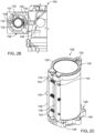
- FIG 1A is a perspective view of a machine 100 for cooling food or drinks.
- Figure 1B shows the machine without its housing.
- the machine 100 reduces the temperature of ingredients in a pod containing the ingredients. Most pods include a mixing paddle used to mix the ingredients before dispensing the cooled or frozen products.
- the machine 100 includes a body 102 that includes a compressor, a condenser, a fan, an evaporator, capillary tubes, a control system, a lid system and a dispensing system with a housing 104 and a pod-machine interface 106.
- the pod-machine interface 106 includes an evaporator 108 of a refrigeration system 109 whose other components are disposed inside the housing 104.
- the machine with the refrigeration system 109 is not according to the claimed invention.
- the evaporator 108 defines a receptacle 110 sized to receive a pod.
- a lid 112 is attached to the housing 104 via a hinge 114.
- the lid 112 can rotate between a closed position covering the receptacle 110 ( Figure 1A ) and an open position exposing the receptacle 110 ( Figure 1B ). In the closed position, the lid 112 covers the receptacle 110 and is locked in place.
- a latch 116 on the lid 112 engages with a latch recess 118 on the pod-machine interface 106.
- a latch sensor 120 is disposed in the latch recess 118 to determine if the latch 116 is engaged with the latch recess 118.
- a processor 122 is electronically connected to the latch sensor 120 and recognizes that the lid 112 is closed when the latch sensor 120 determines that the latch 116 and the latch recess 118 are engaged.
- An auxiliary cover 115 rotates upward as the lid 112 is moved from its closed position to its open position. Some auxiliary covers slide into the housing when the lid moves into the open position.
- the evaporator 108 In the machine 100, the evaporator 108 is fixed in position with respect to the body 102 of the machine 100 and access to the receptacle 110 is provided by movement of the lid 112. In some machines, the evaporator 108 is displaceable relative to the body 102 and movement of the evaporator 108 provides access to the receptacle 110.
- a motor 124 disposed in the housing 104 is mechanically connected to a driveshaft 126 that extends from the lid 112.
- the driveshaft 126 extends into the receptacle 110 and, if a pod is present, engages with the pod to move a paddle or paddles within the pod.
- the processor 122 is in electronic communication with the motor 124 and controls operation of the motor 124.
- the shaft associated with the paddle(s) of the pod extends outward from the pod and the lid 112 has a rotating receptacle (instead of the driveshaft 126) mechanically connected to the motor 124.
- FIG 1C is perspective view of the lid 112 shown separately so the belt 125 that extends from motor 124 to the driveshaft 126 is visible.
- the motor 124 is mounted on a plate that runs along rails 127. The plate can move approximately 0.25 inches to adjust the tension on the belt. During assembly, the plate slides along the rails. Springs disposed between the plate and the lid 112 bias the lid 112 away from the plate to maintain tension in the belt.
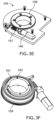
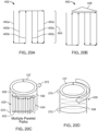
- Figure 2A is a perspective view of the machine 100 with the cover of the pod-machine interface 106 illustrated as being transparent to allow a more detailed view of the evaporator 108 to be seen.
- Figure 2B is a top view of a portion of the machine 100 without housing 104 and the pod-machine interface 106 without the lid 112.
- Figures 2C and 2D are, respectively, a perspective view and a side view of the evaporator 108.
- Other pod-machine interfaces are described in more detail in U.S. Pat. App. Ser. No. (attorney docket number 47354-0009001 ) filed contemporaneously with this application.
- the evaporator 108 has a clamshell configuration with a first portion 128 attached to a second portion 130 by a living hinge 132 on one side and separated by a gap 134 on the other side.
- Refrigerant flows to the evaporator 108 from other components of the refrigeration system through fluid channels 136 (best seen on Figure 2B ).
- the refrigerant flows through the evaporator 108 in internal channels through the first portion 128, the living hinge 132, and the second portion 130.
- the space 137 (best seen on Figure 2B ) between the outer wall of the evaporator 108 and the inner wall of the casing of the pod-machine interface 106 is filled with an insulating material to reduce heat exchange between the environment and the evaporator 108.
- the space 137 is filled with an aerogel (not shown).
- Some machines use other insulating material, for example, an annulus (such as an airspace), insulating foams made of various polymers, or fiberglass wool.
- the evaporator 108 has an open position and a closed position. In the open position, the gap 134 opens to provide an air gap between the first portion 128 and the second portion 130. In the machine 100, the first portion 128 and the second portion 130 are pressed together in the closed position. In some machines, the first and second portion are pressed towards each other and the gap is reduced, but still defined by a space between the first and second portions in the closed position.
- the inner diameter ID of the evaporator 108 is slightly larger in the open position than in the closed position. Pods can be inserted into and removed from the evaporator 108 while the evaporator is in the open position. Transitioning the evaporator 108 from its open position to its closed position after a pod is inserted tightens the evaporator 108 around the outer diameter of the pod.
- the machine 100 is configured to use pods with 2.085" outer diameter.
- the evaporator 108 has an inner diameter of 2.115" in the open position and an inner diameter inner diameter of 2.085" in the closed position.
- the pods can be formed from commercially available can sizes, for example, "slim” cans with diameters ranging from 2.080 inches - 2.090 inches and volumes of 180 milliliters (ml) - 300 ml, "sleek” cans with diameters ranging from 2.250 inches - 2.400 inches and volumes of 180 ml - 400 ml and "standard” size cans with diameters ranging from 2.500 inches - 2.600 inches and volumes of 200 ml - 500 ml.
- the machine 100 is configured to use pods with 2.085 inches outer diameter.
- the evaporator 108 has an inner diameter of 2.115 inches in its open position and an inner diameter inner diameter of 2.085 inches in its closed position. Some machines have evaporators sized and configured to cool other pods.
- the closed position of evaporator 108 improves heat transfer between inserted pod 150 and the evaporator 108 by increasing the contact area between the pod 150 and the evaporator 108 and reducing or eliminating an air gap between the wall of the pod 150 and the evaporator 108.
- the pressure applied to the pod by the evaporator 108 is opposed by the mixing paddles, pressurized gases within the pod, or both to maintain the casing shape of the pod.
- the relative position of the first portion 128 and the second portion 130 and the size of the gap 134 between them is controlled by two bars 138 connected by a bolt 140 and two springs 142.
- Each of the bars 138 has a threaded central hole through which the bolt 140 extends and two end holes engaging the pins 144.
- Each of the two springs 142 is disposed around a pin 144 that extends between the bars 138.
- Some machines use other systems to control the size of the gap 134, for example, circumferential cable systems with cables that extend around the outer diameter of the evaporator 108 with the cable being tightened to close the evaporator 108 and loosened to open the evaporator 108.
- One bar 138 is mounted on the first portion 128 of the evaporator 108 and the other bar 138 is mounted on the second portion 130 of the evaporator 108.
- the bars 138 are integral to the body of the evaporator 108 rather than being mounted on the body of the evaporator.
- the springs 142 press the bars 138 away from each other.
- the spring force biases the first portion 128 and the second portion 130 of the evaporator 108 away from each at the gap 134.
- Rotation of the bolt 140 in one direction increases a force pushing the bars 138 towards each and rotation of the bolt in the opposite direction decreases this force.
- the bars 138 bring the first portion 128 and the second portion 130 of the evaporator together.
- the machine 100 includes an electric motor 146 (shown on Figure 2B ) that is operable to rotate the bolt 140 to control the size of the gap 134.
- Some machines use other mechanisms to rotate the bolt 140.
- some machines use a mechanical linkage, for example, between the lid 112 and the bolt 140 to rotate the bolt 140 as the lid 112 is opened and closed.
- Some machines include a handle that can be attached to the bolt to manually tighten or loosen the bolt.
- Some machines have a wedge system that forces the bars into a closed position when the machine lid is shut. This approach may be used instead of the electric motor 146 or can be provided as a backup in case the motor fails.
- the electric motor 146 is in communication with and controlled by the processor 122 of the machine 100.
- Some electric drives include a torque sensor that sends torque measurements to the processor 122.
- the processor 122 signals to the motor to rotate the bolt 140 in a first direction to press the bars 138 together, for example, when a pod sensor indicates that a pod is disposed in the receptacle 110 or when the latch sensor 120 indicates that the lid 112 and pod-machine interface 106 are engaged. It is desirable that the clamshell evaporator be shut and holding the pod in a tightly fixed position before the lid closes and the shaft pierces the pod and engages the mixing paddle. This positioning can be important for driveshaft-mixing paddle engagement.
- the processor 122 signals to the electric drive to rotate the bolt 140 in the second direction, for example, after the food or drink being produced has been cooled/frozen and dispensed from the machine 100, thereby opening the evaporator gap 134 and allowing for easy removal of pod 150 from evaporator 108.
- the base of the evaporator 108 has three bores 148 (see Figure 2C ) which are used to mount the evaporator 108 to the floor of the pod-machine interface 106. All three of the bores 148 extend through the base of the second portion 130 of the evaporator 108. The first portion 128 of the evaporator 108 is not directly attached to the floor of the pod-machine interface 106. This configuration enables the opening and closing movement described above. Other configurations that enable the opening and closing movement of the evaporator 108 can also be used. Some machines have more or fewer than three bores 148. Some evaporators are mounted to components other than the floor of the pod-machine interface, for example, the dispensing mechanism.
- the evaporators described in this specification can have the following characteristics: Table 1 - Evaporator parameters Mass Velocity 60,000 to 180,000 lb / (hour feet squared) Refrigerant Wetted Surface Area 35 to 200 square inches Pressure drop Through Refrigeration Process less than 2 psi pressure drop across the evaporator Pod/Evaporator Heat Transfer Surface 15 to 50 square inches Mass of Evaporator 0.100 to 1.50 pounds Minimum Conductivity of the Material 160 W/mK The following paragraphs describe the significance of these parameters in more detail.
- Mass velocity accounts for the multi-phase nature or refrigerant flowing through an evaporator.
- the two-phase process takes advantage of the high amounts of heat absorbed and expended when a refrigerant fluid (e.g., R-290 propane) changes state from a liquid to gas and a gas to a liquid, respectively.
- a refrigerant fluid e.g., R-290 propane
- the rate of heat transfer depends in part on exposing the evaporator inner surfaces with a new liquid refrigerant to vaporize and cool the liquid ice cream mix. To do this the velocity of the refrigerant fluid must be high enough for vapor to channel or flow down the center of the flow path within the walls of evaporator and for liquid refrigerant to be pushed thru these channel passages within the walls.
- the nominal operating pressure of the evaporator is determined by the required temperature of the evaporator and the properties of the refrigerant used in the system.
- the mass flow rate of refrigerant through the evaporator must be high enough for it to absorb the amount of thermal energy from the confection to freeze it, in a given amount of time.
- Mass flow rate is primarily determined by the size of the compressor. It is desirable to use the smallest possible compressor to reduce, cost, weight and size.
- the convective heat transfer coefficient is influenced by the mass velocity and wetted surface area of the evaporator. The convective heat transfer coefficient will increase with increased mass velocity. However, pressure drop will also increase with mass velocity. This in turn increases the power required to operate the compressor and reduces the mass flow rate the compressor can deliver.
- evaporators with a mass velocity of 75,000 - 125,000 lb/hr ft ⁇ 2 are effective in helping provide a system capable of freezing up to 12 ounces of confection in less than 2 minutes.
- the latest prototype has a mass velocity of approximately 100,000 lb/hr ft ⁇ 2 and provides a good balance of high mass velocity, manageable pressure drop in the system, and a reasonable sized compressor.
- Another important factor that affects performance in an evaporator is the surface area wetted by refrigerant which is the area of all the cooling channels within the evaporator exposed to refrigerant. Increasing the wetted surface area can improve heat transfer characteristics of an evaporator. However, increasing the wetted surface area can increase the mass of the evaporator which would increase thermal inertia and degrade heat transfer characteristics of the evaporator.
- the amount of heat that can be transferred out of the liquid in a pod is proportional to the surface area of the pod / evaporator heat transfer surface.
- a larger surface area is desirable but increases in surface area can require increasing the mass of the evaporator which would degrade heat transfer characteristics of the evaporator.
- evaporators in which the area of the pod/evaporator heat transfer surface is between 20 and 40 square inches are effectively combined with the other characteristics to help provide a system capable of freezing up to 12 ounces of confection in less than 2 minutes.
- Thermal conductivity is the intrinsic property of a material which relates its ability to conduct heat. Heat transfer by conduction involves transfer of energy within a material without any motion of the material as a whole.
- An evaporator with walls made of a high conductivity material reduces the temperature difference across the evaporator walls. Reducing this temperature difference reduces the work required for the refrigeration system to cool the evaporator to the right temperature.
- the evaporator For the desired heat transfer to occur, the evaporator must be cooled. The greater the mass of the evaporator, the longer this cooling will take. Reducing evaporator mass reduces the amount of material that must be cooled during a freezing cycle. An evaporator with a large mass will increase the time require to freeze up to 12 ounces of confection.
- thermal conductivity and mass can be balanced by an appropriate choice of materials.
- materials with higher thermal conductivity than aluminum such as copper.
- density of copper is greater that the density of aluminum.
- some evaporators have been constructed that use high thermal conductive copper only on the heat exchange surfaces of the evaporator and use aluminum everywhere else.
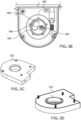
- Figures 3A - 3F show components of the pod-machine interface 106 that are operable to open pods in the evaporator 108 to dispense the food or drink being produced by the machine 100. This is an example of one approach to opening pods but some machines and the associated pods use other approaches.
- Figure 3A is a partially cutaway schematic view of the pod-machine interface 106 with a pod 150 placed in the evaporator 108.
- Figure 3B is a schematic plan view looking upwards that shows the relationship between the end of the pod 150 and the floor 152 of the pod-machine interface 106.
- the floor 152 of the pod-machine interface 106 is formed by a dispenser 153.
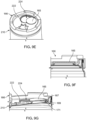
- Figures 3C and 3D are perspective views of a dispenser 153.
- Figures 3E and 3F are perspective views of an insert 154 that is disposed in the dispenser 153.
- the insert 154 includes an electric motor 146 operable to drive a worm gear 157 floor 152 of the pod-machine interface 106.
- the worm gear 157 is engaged with a gear 159 with an annular configuration.
- An annular member 161 mounted on the gear 159 extends from the gear 159 into an interior region of the pod-machine interface 106.
- the annular member 161 has protrusions 163 that are configured to engage with a pod inserted into the pod-machine interface 106 to open the pod.
- the protrusions 163 of the annular member 161 are four dowel-shaped protrusions. Some annular gears have more protrusions or fewer protrusions and the protrusions can have other shapes, for example, "teeth.”
- the pod 150 includes a body 158 containing a mixing paddle 160 (see Figure 3A ).
- the pod 150 per se is not part of the claimed invention.
- the pod 150 also has a base 162 defining an aperture 164 and a cap 166 extending across the base 162 (see Figure 3B ).
- the base 162 is seamed/fixed onto the body 158 of the pod 150.
- the base 162 includes a protrusion 165.
- the cap 166 mounted over base 162 is rotatable around the circumference/axis of the pod 150. In use, when the product is ready to be dispensed from the pod 150, the dispenser 153 of the machine engages and rotates the cap 166 around the first end of the pod 150. Cap 166 is rotated to a position to engage and then separate the protrusion 165 from the rest of the base 162.
- the pod 150 and its components are described in more detail with respect to Figures 6A-10 .
- the aperture 164 in the base 162 is opened by rotation of the cap 166.
- the pod-machine interface 106 includes an electric motor 146 with threading that engages the outer circumference of a gear 168. Operation of the electric motor 146 causes the gear 168 to rotate.
- the gear 168 is attached to a annular member 161 and rotation of the gear 168 rotates the annular member 161.
- the gear 168 and the annular member 161 are both annular and together define a central bore through which food or drink can be dispensed from the pod 150 through the aperture 164 without contacting the gear 168 or the annular member 161.
- the annular member 161 engages the cap 166 and rotation of the annular member 161 rotates the cap 166.
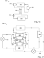
- FIG. 4 is a schematic of the refrigeration system 109, which is not according to the claimed invention and that includes the evaporator 108.
- the refrigeration system also includes a condenser 180, a suction line heat exchanger 182, an expansion valve 184, and a compressor 186.
- High-pressure, liquid refrigerant flows from the condenser 180 through the suction line heat exchanger 182 and the expansion valve 184 to the evaporator 108.
- the expansion valve 184 restricts the flow of the liquid refrigerant fluid and lowers the pressure of the liquid refrigerant as it leaves the expansion valve 184.
- the low-pressure liquid-vapor mixture then moves to the evaporator 108 where heat absorbed from a pod 150 and its contents in the evaporator 108 changes the refrigerant from a liquid-vapor mixture to a gas.
- the gas-phase refrigerant flows from the evaporator 108 to the compressor 186 through the suction line heat exchanger 182.
- the cold vapor leaving the evaporator 108 pre-cools the liquid leaving the condenser 180.
- the refrigerant enters the compressor 186 as a low-pressure gas and leaves the compressor 186 as a high-pressure gas.
- the gas then flows to the condenser 180 where heat exchange cools and condenses the refrigerant to a liquid.
- the refrigeration system 109 includes a first bypass line 188 and second bypass line 190.
- the first bypass line 188 directly connects the discharge of the compressor 186 to the inlet of the compressor 186.
- Disposed on the both the first bypass line and second bypass line are bypass valves that open and close the passage to allow refrigerant bypass flow. Diverting the refrigerant directly from the compressor discharge to the inlet can provide evaporator defrosting and temperature control without injecting hot gas to the evaporator.
- the first bypass line 188 also provides a means for rapid pressure equalization across the compressor 186, which allows for rapid restarting (i.e., freezing one pod after another quickly).
- the second bypass line 190 enables the application of warm gas to the evaporator 108 to defrost the evaporator 108.
- the bypass valves may be, for example, solenoid valves or throttle valves.
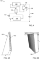
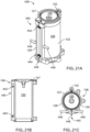
- FIGS 5A and 5B are views of a prototype of the condenser 180.
- the condenser has internal channels 192.
- the internal channels 192 increase the surface area that interacts with the refrigerant cooling the refrigerant quickly.
- These images show micro-channel tubing which are used because they have small channels which keeps the coolant velocity up and are thin wall for good heat transfer and have little mass to prevent the condenser for being a heat sink.
- Figures 6A and 6B show an example of a pod 150 for use with the machine 100 described with respect to Figures 1A - 3F .
- Figure 6A is a side view of the pod 150.
- Figure 6B is a schematic side view of the pod 150 and the mixing paddle 160 disposed in the body 158 of the pod 150.
- Other pod-machine interfaces that can be used with this and similar machines are described in more detail in U.S. Pat. App. Ser. No. (attorney docket number 47354-0010001) filed contemporaneously with this application.
- the pod 150 is sized to fit in the receptacle 110 of the machine 100.
- the pods can be sized to provide a single serving of the food or drink being produced.
- pods typically have a volume between 6 and 18 fluid ounces.
- the pod 150 has a volume of approximately 8.5 fluid ounces.
- the body 158 of the pod 150 is a can that contains the mixing paddle 160.
- the body 158 extends from a first end 210 at the base to a second end 212 and has a circular cross-section.
- the first end 210 has a diameter D UE that is slightly larger than the diameter D LE of the second end 212. This configuration facilitates stacking multiple pods 200 on top of one another with the first end 210 of one pod receiving the second end 212 of another pod.
- a wall 214 connects the first end 210 to the second end 212.
- the wall 214 has a first neck 216, second neck 218, and a barrel 220 between the first neck 216 and the second neck 218.
- the barrel 220 has a circular cross-section with a diameter D B .
- the diameter D B is larger than both the diameter D UE of the first end 210 and the diameter D LE of the second end 212.
- the first neck 216 connects the barrel 220 to the first end 210 and slopes as the first neck 216 extends from the smaller diameter D UE to the larger diameter D B the barrel 220.
- the second neck 218 connects the barrel 220 to the second end 212 and slopes as the second neck 218 extends from the larger diameter D B of the barrel 220 to the smaller diameter D LE of the second end 212.
- the second neck 218 is sloped more steeply than the first neck 216 as the second end 212 has a smaller diameter than the first end 210.
- This configuration of the pod 150 provides increased material usage; i.e., the ability to use more base material (e.g., aluminum) per pod. This configuration further assists with the columnar strength of the pod.
- the pod 150 is designed for good heat transfer from the evaporator to the contents of the pod.
- the body 158 of the pod 150 is made of aluminum and is between 5 and 50 microns thick.
- the bodies of some pods are made of other materials, for example, tin, stainless steel, and various polymers such as Polyethylene terephthalate (PTE).
- PTE Polyethylene terephthalate
- Pod 150 may be made from a combination of different materials to assist with the manufacturability and performance of the pod.
- the pod walls and the second end 212 may be made of Aluminum 3104 while the base may be made of Aluminum 5182.
- the internal components of the pod are coated with a lacquer to prevent corrosion of the pod as it comes into contact with the ingredients contained within pod.
- This lacquer also reduces the likelihood of "off notes" of the metal in the food and beverage ingredients contained within pod.
- a pod made of aluminum may be internally coated with one or a combination of the following coatings: Sherwin Williams/Valspar V70Q11, V70Q05, 32SO2AD, 40Q60AJ; PPG Innovel 2012-823, 2012-820C; and/or Akzo Nobel Aqualure G1 50.
- Other coatings made by the same or other coating manufacturers may also be used.
- Some mixing paddles are made of similar aluminum alloys and coated with similar lacquers/coatings.
- Whitford/PPG coating 8870 may be used as a coating for mixing paddles.
- the mixing paddle lacquer may have additional non-stick and hardening benefits for mixing paddle.
- Figures 7A - 7C illustrate the engagement between the driveshaft 126 of the machine 100 and the mixing paddle 160 of a pod 150 inserted in the machine 100.
- Figures 7A and 7B are perspective views of the pod 150 and the driveshaft 126.
- the pod 150 is inserted into the receptacle 110 of the evaporator 108 with the first end 210 of the pod 150 downward. This orientation exposes the second end 212 of the pod 150 to the driveshaft 126 as shown in Figure 7A .
- Closing the lid 112 presses the driveshaft 126 against the second end 212 of the pod 150 with sufficient force that the driveshaft 126 pierces the second end 212 of the pod 150.
- Figure 7B shows the resulting hole exposing the mixing paddle 160 with the driveshaft 126 offset for ease of viewing.
- Figure 7C is a cross-section of a portion of the pod 150 with the driveshaft 126 engaged with the mixing paddle 160 after the lid is closed.
- there is not a tight seal between the driveshaft 126 and the pod 150 so that air can flow in as the frozen confection is evacuating/dispensing out the other end of the pod 150.
- there is a tight seal such that the pod 150 retains pressure in order to enhance contact between the pod 150 and evaporator 108.
- Some mixing paddles contain a funnel or receptacle configuration that receives the punctured end of the second end of the pod when the second end is punctured by driveshaft.
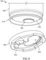
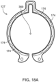
- Figure 8 shows the first end 210 of the pod 150 with the cap 166 spaced apart from the base 162 for ease of viewing.
- Figures 9A - 9D illustrate rotation of the cap 166 around the first end 210 of the pod 150 to cut and carry away protrusion 165 of base 162 and expose aperture 164 extending through the base 162.
- the base 162 is manufactured separately from the body 158 of the pod 150 and then attached (for example, by crimping or seaming) to the body 158 of the pod 150 covering an open end of the body 158.
- the protrusion 165 of the base 162 can be formed, for example, by stamping, deep drawing, or heading a sheet of aluminum being used to form the base.
- the protrusion 165 is attached to the remainder of the base 162, for example, by a weakened score line 173.
- the scoring can be a vertical score into the base of the aluminum sheet or a horizontal score into the wall of the protrusion 165.
- the material can be scored from an initial thickness of 0.008 inches to 0.010 inches to a post-scoring thickness of 0.001 inches - 0.008 inches.
- the cap 166 has a first aperture 222 and a second aperture 224.
- the first aperture approximately matches the shape of the aperture 164.
- the aperture 164 is exposed and extends through the base 162 when the protrusion 165 is removed.
- the second aperture 224 has a shape corresponding to two overlapping circles.
- One of the overlapping circles has a shape that corresponds to the shape of the protrusion 165 and the other of the overlapping circles is slightly smaller.
- a ramp 226 extends between the outer edges of the two overlapping circles. There is an additional 0.020" material thickness at the top of the ramp transition. This extra height helps to lift and rupture the protrusion's head and open the aperture during the rotation of the cap as described in more detail with reference to Figures 9A - 9G
- the cap 166 is initially attached to the base 162 with the protrusion 165 aligned with and extending through the larger of the overlapping circles of the second aperture 224.
- the processor 122 of the machine activates the electric motor 146 to rotate the gear 168 and the annular member 161, rotation of the cap 166 slides the ramp 226 under a lip of the protrusion 165 as shown in Figures 9C and 9D .
- the protrusion 165 has a head 167, a stem 169, and a foot 171 (best seen in Figure 9G ).
- the stem 169 extends between the head 167 and the foot 171 and has a smaller cross-section that the head 167 and the foot 171.
- the cap 166 presses laterally against the stem 169 with the head 167 and the foot 171 bracketing the cap 166 along the edges of one of the overlapping circles of the second aperture 224.
- This configuration retains the protrusion 165 when the protrusion 165 is separated from the base 166.
- Such a configuration reduces the likelihood that the protrusion falls into the waiting receptacle that when the protrusion 165 is removed from the base.
- the base has a rotatable cutting mechanism that is riveted to the base.
- the rotatable cutting mechanism has a shape similar to that described relative to cap 166 but this secondary piece is riveted to and located within the perimeter of base 162 rather than being mounted over and around base 162.
- the processor 122 of the machine activates an arm of the machine to rotate the riveted cutting mechanism around a rivet.
- the cutting mechanism engages, cuts and carries away the protrusion 165, leaving the aperture 164 of base 162 in its place.
- some pods have caps with a sliding knife that moves across the base to remove the protrusion.
- the sliding knife is activated by the machine and, when triggered by the controller, slides across the base to separate, remove, and collect the protrusion 165.
- the cap 166 has a guillotine feature that, when activated by the machine, may slide straight across and over the base 162.
- the cap 166 engages, cuts, and carries away the protrusion 165.
- this guillotine feature may be central to the machine and not the cap 166 of pod 150.
- this guillotine feature may be mounted as a secondary piece within base 162 and not a secondary mounted piece as is the case with cap 166.
- Some pods have a dispensing mechanism that includes a pop top that can be engaged and released by the machine.
- a dispensing mechanism that includes a pop top that can be engaged and released by the machine.
- an arm of the machine engages and lifts a tab of the pod, thereby pressing the puncturing the base and creating an aperture in the base. Chilled or frozen product is dispensed through the aperture.
- the punctured surface of the base remains hinged to base and is retained inside the pod during dispensing.
- the mixing avoids or rotates over the punctured surface or, in another embodiment, so that the mixing paddle continues to rotate without obstruction.
- the arm of the machine separates the punctured surface from the base.
- FIG 10 is an enlarged schematic side view of the pod 150.
- the mixing paddle 160 includes a central stem 228 and two blades 230 extending from the central stem 228.
- the blades 230 are helical blades shaped to churn the contents of the pod 150 and to remove ingredients that adhere to inner surface of the body 158 of the pod 150.
- Some mixing paddles have a single blade and some mixing paddles have more than two mixing paddles.
- Fluids for example, liquid ingredients, air, or frozen confection
- openings 232 in the blades 230 when the mixing paddle 160 rotates.
- These openings reduce the force required to rotate the mixing paddle 160. This reduction can be significant as the viscosity of the ingredients increases (e.g., as ice cream forms).
- the openings 232 further assist in mixing and aerating the ingredients within the pod.
- the lateral edges of the blades 230 define slots 234.
- the slots 234 are offset so that most of the inner surface of the body 158 is cleared of ingredients that adhere to inner surface of the body by one of the blades 230 as the mixing paddle 160 rotates.
- the mixing paddle is 160 wider than the first end 210 of the body 158 of the pod 150
- the slots 234 are alternating slots that facilitate insertion of the mixing paddle 160 into the body 158 of the pod 150 by rotating the mixing paddle 160 during insertion so that the slots 234 are aligned with the first end 210.
- the outer diameter of the mixing paddle are less than the diameter of the pod 150 opening, allowing for a straight insertion (without rotation) into the pod 150.
- one blade on the mixing paddle has an outer-diameter that is wider than the second blade diameter, thus allowing for straight insertion (without rotation) into the pod 150.
- one blade is intended to remove (e.g., scrape) ingredients from the sidewall while the second, shorter diameter blade, is intended to perform more of a churning operation.
- Some mixing paddles have one or more blades that are hinged to the central stem. During insertion, the blades can be hinged into a condensed formation and released into an expanded formation once inserted. Some hinged blades are fixed open while rotating in a first direction and collapsible when rotating in a second direction, opposite the first direction. Some hinged blades lock into a fixed, outward, position once inside the pod regardless of rotational directions. Some hinged blades are manually condensed, expanded, and locked.
- the mixing paddle 160 rotates clockwise and removes frozen confection build up from the pod 214 wall. Gravity forces the confection removed from the pod wall to fall towards first end 210. In the counterclockwise direction, the mixing paddle 160 rotate, lift and churn the ingredients towards the second end 212. When the paddle changes direction and rotates clockwise the ingredients are pushed towards the first end 210. When the protrusion 165 of the base 162 is removed as shown and described with respect to Figure 9D , clockwise rotation of the mixing paddle dispenses produced food or drink from the pod 150 through the aperture 164. Some paddles mix and dispense the contents of the pod by rotating a first direction. Some paddles mix by moving in a first direction and a second direction and dispense by moving in the second direction when the pod is opened.
- the central stem 228 defines a recess 236 that is sized to receive the driveshaft 126 of the machine 100.
- the recess and driveshaft 126 have a square cross section so that the driveshaft 126 and the mixing paddle 160 are rotatably constrained. When the motor rotates the driveshaft 126, the driveshaft rotates the mixing paddle 160.
- the cross section of the driveshaft is a different shape and the cross section of the recess is compatibly shaped.
- the driveshaft and recess are threadedly connected.
- the recess contains a mating structure that grips the driveshaft to rotationally couple the driveshaft to the paddle.
- Figure 11 is a flow chart of a method 250 implemented on the processor 122 for operating the machine 100.
- the method 250 is described with references to refrigeration system 109 and machine 100.
- the method 250 may also be used with other refrigeration systems and machines.
- the method 250 is described as producing soft serve ice cream but can also be used to produce other cooled or frozen drinks and foods.
- the first step of the method 250 is to turn the machine 100 on (step 260) and turn on the compressor 186 and the fans associated with the condenser 180 (step 262).
- the refrigeration system 109 then idles at regulated temperature (step 264).
- the evaporator 108 temperature is controlled to remain around 0.75°C but may fluctuate by ⁇ 0.25°C. Some machines are operated at other idle temperatures, for example, from 0.75°C to room temperature (22.0°C).
- the processor 122 opens the bypass valve 190 to increase the heat of the system (step 266). When the evaporator temperature goes over 1°C, the bypass valve 190 is closed to cool the evaporator (step 268). From the idle state, the machine 100 can be operated to produce ice cream (step 270) or can shut down (step 272).
- the bypass valve 190 closes, the evaporator 108 moves to its closed position, and the motor 124 is turned on (step 274).
- the evaporator is closed electronically using a motor.
- the evaporator is closed mechanically, for example by the lid moving from the open position to the closed position.
- a sensor confirms that a pod 150 is present in the evaporator 108 before these actions are taken.
- RFID radio frequency identification
- UPC bar or QR codes QR codes
- Identification information on pods can be used to trigger specific cooling and mixing algorithms for specific pods.
- These systems can optionally read the RFID, QR code, or barcode and identify the mixing motor speed profile and the mixing motor torque threshold (step 273).
- the identification information can also be used to facilitate direct to consumer marketing (e.g., over the internet or using a subscription model).
- This approach and the systems described in this specification enable selling ice cream thru e-commerce because the pods are shelf stable.
- customers pay a monthly fee for a predetermined number of pods shipped to them each month. They can select their personalized pods from various categories (e.g., ice cream, healthy smoothies, frozen coffees or frozen cocktails) as well as their personalized flavors (e.g., chocolate or vanilla).
- the identification can also be used to track each pod used.
- the machine is linked with a network and can be configured to inform a vendor as to which pods are being used and need to be replaced (e.g., through a weekly shipment). This method is more efficient than having the consumers go to the grocery store and purchase pods.
- a torque sensor of the machine measures the torque of the motor 124 required to rotate the mixing paddle 160 within the pod 150. Once the torque of the motor 124 measured by a torque sensor satisfies a predetermined threshold, the machine 100 moves into a dispensing mode (276). The dispensing port opens and the motor 124 reverses direction (step 278) to press the frozen confection out of the pod 150. This continues for approximately 1 to 10 seconds to dispense the contents of the pod 150 (step 280). The machine 100 then switches to defrost mode (step 282).
- the evaporator 108 can freeze to the pod 150, the first portion 128 and second portion 130 of the evaporator can freeze together, and/or the pod can freeze to the evaporator.
- the evaporator can be defrosted between cycles to avoid these issues by opening the bypass valve 170, opening the evaporator 108, and turning off the motor 124 (step 282).
- the machine then diverts gas through the bypass valve for about 1 to 10 seconds to defrost the evaporator (step 284).
- the machine is programmed to defrost after every cycle, unless a thermocouple reports that the evaporator 108 is already above freezing.
- thermometer measures the temperature of the contents of pod 150 and identifies when it is time to dispense the contents of the pod.
- the dispensing mode begins when a predetermined time is achieved.
- a combination of torque required to turn the mixing paddle, mixing motor current draw, temperature of the pod, and/or time determines when it is time to dispense the contents of the pod.
- the machine 100 automatically powers down (step 272). A user can also power down the machine 100 by holding down the power button (286). When powering down, the processor opens the bypass valve 190 to equalize pressure across the valve (step 288). The machine 100 waits ten seconds (step 290) then turns off the compressor 186 and fans (step 292). The machine is then off.
- Figure 12 is a schematic of a preferred embodiment of the refrigeration system 310 of the machine of the present invention, which system 310, according to the invention, includes the evaporator 108 and an expansion sub-system 312.
- the refrigeration system 310 is substantially similar to the refrigeration system 109.
- the refrigeration system 310 includes the expansion sub-system 312 rather than the expansion valve 184 shown in the refrigeration system 109.
- the refrigeration system 310 does not include the first bypass line 188 and the second bypass line 190 that are part of the refrigeration system 109.
- some systems include the with the expansion sub-system 312, the first bypass line, and the second bypass line.
- the expansion sub-system 312 includes multiple valves to control expansion of the refrigeration fluid. According to the invention, these valves include a first fixed orifice valve 314, a second fixed orifice valve 316, and a control valve 318.
- the control valve 318 is upstream from the second fixed orifice valve 316.
- the control valve 318 and second fixed orifice valve 316 are in parallel with the first fixed orifice valve 314.
- the expansion device has two modes to control the temperature of the refrigerant entering the evaporator 108. In the first mode, the control valve 318 is open allowing the refrigerant to flow to the second fixed orifice valve 316.
- the refrigerant flows through both the first fixed orifice valves 314 and the second fixed orifice valves 316.
- the control valve 318 is closed and the refrigerant does not flow through the second fixed orifice valve 316. All refrigerant flows through the first fixed orifice valve 314.
- the expansion valve 184 or expansion sub-system 312 receives a high-pressure refrigerant and releases low-pressure refrigerant. This pressure drop cools the refrigerant. Larger changes in pressure ( ⁇ P) cause larger changes in temperature ( ⁇ T). In the second mode (i.e., with control valve 318 closed), the pressure drop through the expansion sub-system 312 will be higher than in the first mode providing a lower evaporator pressure and associated lower evaporator temperature. The effect on heat transfer of the increased temperature differential between the refrigerant and the contents of a pod in the evaporator 108 is offset to some extent by the fact that this lower pressure refrigerant is less dense.
- the refrigeration system 310 is in the first mode.
- the control valve 318 is open and the refrigerant flows through both the first fixed orifice valve 314 and second fixed orifice valve 316. This results in the evaporator operating at around a temperature of -20 °C to -10 °C. At this temperature, the cooling system provides more cooling capacity than it can at lower temperatures by taking advantage of the higher density refrigerant passing through the evaporator.
- the pod 150 is inserted into the evaporator 108 around room temperature (e.g., 22°C).
- room temperature e.g. 22°C
- the initial difference in temperature between the evaporator 108 and the pod 150 is high.
- the heat transfers rapidly from the pod 150 to the evaporator 108.
- the difference between the temperature of the pod 150 and the evaporator 108 decreases as the pod 150 cools and the transfer of heat from the pod 150 to the evaporator 108 also slows.
- the system 310 enters the second mode and the control valve 318 closes.
- the refrigerant flows only through the first fixed orifice valve 314 and the ⁇ P between the refrigerant entering the first fixed orifice valve 314 and exiting the first fixed orifice valve 314 increases.
- the ⁇ T also increases resulting in a colder evaporator 108 with temperatures of approximately -15 °C to -30°C. This reduces the cooling capacity of the system, but increases the temperature difference between the pod and nest, which allows for quick final freezing of the ice cream.
- the second mode activated when the temperature difference between the pod and evaporator reduces to the point of impacting heat transfer, the lower refrigerant temperature augments the overall heat transfer even through less mass is flowing in the system.
- the temperature of the evaporator in the first mode is above freezing. This configuration can precool the evaporator before use and defrost the evaporator after use.
- the configuration of the refrigeration system 310 increases temperature control, which can reduce freezing time and reduce the required compressor output.
- the reduction in required compressor output allows for a reduction in the size of the compressor.
- the expansion sub-system includes more than two valves.
- the multi-valve sub-systems can have more than two modes, further increasing temperature control.
- thermostatic expansion valves and electronic expansion valves.
- Both thermostatic expansion valves and electronic expansion valves can adapt the orifice size based on various loads and operating conditions.
- the thermostatic expansion valves sense the evaporator outlet temperature of the refrigerant and adjusts flow through the thermostatic expansion valve to maintain predetermined or desired operating conditions.
- the electronic expansion valves are electrically actuated to adapt the orifice size based on evaporator outlet temperature and electronic signals from a control unit 371.
- Figure 13 is a schematic of a refrigeration system 320, not according to the claimed invention, that includes a refrigerant line 322 that pre-chills a tank 324 of water prior to entering the evaporator 108.
- the refrigeration system 320 is substantially similar to the refrigeration system 109. However, the refrigeration system 320 includes the pre-chilling line 322 and omits the first bypass line 188 and the second bypass line 190 that are part of the refrigeration system 109. Some systems include the first bypass line, the second bypass line, and the pre-chilling line.
- the refrigeration system 320 is used in machines include the water tank 324.
- Machines with water tanks inject fluid into the pod during mixing, for example, to dissolve dry ingredients or dilute the contents of the pod. Chilled water freezes more quickly than hot or room temperature water.
- a valve 326 is operated to route refrigerant through pre-chilling to route refrigerant exiting the expansion valve 184 through the pre-chilling line 322.
- the cold, low-pressure refrigerant flows through the pre-chilling line 322 that is partially or fully disposed in the water tank 324. If the water tank 324 is filled with water, the pre-chilling line 322 is partially or fully submerged in the water.
- the refrigerant cools the water in the water tank 324 and exits the pre-chilling line 322.
- the refrigerant then enters the evaporator 108 to cool the evaporator 108.
- Figure 14 is a schematic of a refrigeration system 328, not according to the claimed invention, that includes a thermal mass 330 disposed between the compressor 186 and the condenser 180.
- the refrigeration system 328 is substantially similar to the refrigeration system 109. However, the refrigeration system 328 includes the thermal mass 330.
- the refrigeration system 328 does not include the first bypass line 188 and the second bypass line 190 that are part of the refrigeration system 109. Some systems include the first bypass line, the second bypass line, and the thermal mass 330.
- the thermal mass may be, for example, ethylene glycol and water mixture, saltwater, paraffin wax (alkanes) or pure water.
- the thermal mass 330 is disposed between the condenser 180 and heat exchanger 182.
- the thermal mass 330 stores thermal energy and releases thermal energy at a later time.
- the thermal mass 330 stores heat emitted from the refrigerant.
- the refrigerant is a high-pressure vapor.
- the condenser 180 isothermally releases heat from the high-pressure vapor to produce a high-pressure liquid. Precooling the vapor refrigerant with the thermal mass 330 reduces the load of the compressor 186.
- the thermal mass 330 releases heat into the environment and reaches an equilibrium at ambient temperatures.
- Some systems not according to the claimed invention include both the second bypass line and the thermal mass.
- the second bypass line redirects refrigerant from the thermal mass, idling the refrigeration system. During this idling period, the thermal mass releases heat from previous cycles into the environment.
- Figure 15 is a schematic of a refrigeration system, not according to the claimed invention, that includes a pressure vessel 334, a first isolation valve 338, and a second isolation valve 336.
- the pressure vessel 334 can act as pressure reservoir that enables rapid startup of the system and decreases the time required to cool (e.g., to freezing) contents of a pod in the evaporator 108.
- the refrigeration system 332 is substantially similar to the refrigeration system 109. However, the refrigeration system 332 includes the pressure vessel 334, the first isolation valve 338, and the second isolation valve 336.
- the refrigeration system 332 further does not include the first bypass line 188 and the second bypass line 190 that are part of the refrigeration system 109. Some systems include the first bypass line, the second bypass line, the pressure vessel 334, the first isolation valve 338, and the second isolation valve 336.
- the second isolation valve 336 is disposed between the compressor 186 and the condenser 180.
- the first isolation valve 338 is disposed between the heat exchanger 182 and the expansion valve 184.
- the pressure vessel 334 is disposed between the condenser 180 and the heat exchanger 182.
- the refrigerant exits the compressor 186 at a high-pressure and maintains that high-pressure until the liquid refrigerant is released by the expansion valve 184.
- the system 332 controls the position of the valves 336, 338 (e.g., open or closed) based on the desired outcome.
- both the first isolation valve 338 and the second isolation valve 336 are open. Prior to idling, the first isolation valve 338 closes and the second isolation valve 336 remains open.
- the compressor 186 continues to run for a short time, for example, 1 - 5 seconds, before the second isolation valve 336 closes. After the second isolation valve 336 closes, the compressor shuts down.
- the compressor 186 restarts, the second isolation valve 336 opens, and the first isolation valve 338 opens. Because high-pressure fluid is already present in the pressure vessel 334, high-pressure refrigerant flows through the expansion valve 184 with the pressure drop cooling the refrigerant.
- This approach decreases the time required to cool the contents of a pod relative to refrigeration systems that allow to system pressures to return to ambient conditions when shutting down. If the system is at ambient conditions, no pressure drop occurs across the expansion valve initially when restarting the system. This approach has demonstrated to decrease the time required to cool the contents of a 8-ounce pod from room temperature to freezing to less than 90 seconds.
- the refrigeration system 332 is able to cool the refrigerant quickly or instantaneously when the system 332 initiates or boots up, for example prior to the insertion of a pod 150.
- Figure 16 is a schematic of a refrigeration system 340, not according to the claimed invention, that includes a thermoelectric module 342.
- the refrigeration system 340 is substantially similar to the refrigeration system 109. However, does not include the first bypass line 188 and the second bypass line 190 that are part of the refrigeration system 109. Some systems include the first bypass line, the second bypass line, and thermoelectric module 342.
- Thermoelectric module 342 is a cooling element disposed between the condenser 180 and the heat exchanger 182.
- the thermoelectric module 342 cools the refrigerant that exits the condenser 180 prior to transferring heat to the refrigerant vapor exiting the evaporator 108 in the heat exchanger 182. Cooling the liquid refrigerant prior to expansion increases the cooling capacity of the system 340 and reduce the required compressor output. The reduction in required compressor output reduces the size of the compressor needed.
- Figure 17 is a schematic of a refrigeration system 344, not according to the claimed invention, that includes a thermal battery 346, a first battery bypass valve 348, and a second battery bypass valve 350.
- the refrigeration system 344 is substantially similar to the refrigeration system 109but does not include the first bypass line 188 that is part of the refrigeration system 109. Some systems with the thermal battery 346 and associated valves also includes the first bypass line.
- the thermal battery 346 has a first portion 352 that is disposed between the heat exchanger 182 and the expansion valve 184.
- the first battery bypass valve 348 is disposed on a first branch line 354 that bypasses the first portion 352 of the thermal battery 346.
- the thermal battery 346 has a high pressure drop.
- the refrigerant primarily flows through the branch line 354 because the branch line 354 has a comparatively low pressure drop to the thermal battery 346.
- the first battery bypass valve 348 is closed, the refrigerant flows through the first portion 352 of the thermal battery 346.
- the thermal battery 346 has a second portion 356, thermally connected to the first portion 352, that is disposed between the evaporator 108 and the heat exchanger 182.
- the second battery bypass valve 350 is disposed on a second branch line 358 that bypasses the second portion 356 of the thermal battery 346.
- the thermal battery 346 has a high pressure drop.
- the refrigerant primarily flows through the branch line 358 because the branch line 358 has a comparatively low pressure drop to the thermal battery 346.
- the second battery bypass valve 350 is closed, the refrigerant flows through the second portion 356 of the thermal battery 346.
- the thermal battery 346 includes a thermal material that retains heat.
- the thermal battery 346 includes a reservoir 360 with a phase change material (e.g., paraffin) receives heat or emits heat, depending on the position of the first battery bypass valve 348 and the second battery bypass valve 350.
- a phase change material e.g., paraffin
- the thermal battery 346 is described as using paraffin as an example of a phase change material.
- Some thermal batteries include other materials that retain heat or expend heat, for example ethylene glycol and water mixture, saltwater or pure water.
- the thermal battery 346 emits heat from its second portion 356 to the refrigerant when the first battery bypass valve 348 is open and the second battery bypass valve 350 is closed. If the paraffin is warm or melted, the cold refrigerant will chill and solidify the paraffin in the reservoir 360. By heating the low-pressure refrigerant, the thermal battery reducing the likelihood that liquid refrigerant will flow into the compressor.
- the thermal battery 346 receives heat at the first portion 352 from the refrigerant when the first battery bypass valve 348 is closed and the second battery bypass valve 350 is open. If the wax is solidified, the hot liquid refrigerant will heat and melt the wax in the wax reservoir 360. If the wax is liquid, the hot refrigerant will continue to heat the liquid wax in the wax reservoir 360.
- both the first battery bypass valve 348 and the second battery bypass valve 350 are open and little to no refrigerant flows interacts with the thermal battery 346.
- the second battery bypass valve 350 closes and the reservoir 360 cools due to the cold, low-pressure refrigerant.
- the second battery bypass valve 350 opens, and the first battery bypass valve 348 closes.
- the first portion 352 of the thermal battery 346 then pre-cools the hot liquid refrigerant exiting the condenser 180 via the heat exchanger 182.
- This configuration can prevent end-of-cycle compressor flooding and can reduce the output of the compressor by reducing the heat load on the compressor.
- Some waxes may have a melting point in a range of 5°C - 10°C, for example, Dodecane wax or Tridecane wax.
- Figure 18A is top view of an evaporator cover 127 and Figure 18B is a top view of the body of the evaporator 108 according to a preferred embodiment of the invention.
- the body of the evaporator 108 defines the channels 366 through which refrigerant flows to cool the evaporator 108.
- the channels 366 are open at a lip 367, as shown in Figure 18B , of the evaporator 108.
- the channels 366 are also open at the opposite end of the evaporator 108 with a similarly configured lip.
- the cover 127 includes multiple recesses 174 that align with four adjacent channels 366 of the evaporator 108 when the cover 127 is attached to the body of the evaporator 108. Some covers include recesses that align with other numbers of adjacent channels. The recesses 174 act as manifolds fluidly connect the adjacent channels 366. The cover 127 on the opposite ends of the body of the evaporator are offset so that the two covers 127 and the body of the evaporator 108 together define a serpentine flow path through the evaporator 108.
- the cover 127 has an inlet 370 and an outlet 372 that fluidly connects the evaporator 108 to the refrigeration system 109.
- Refrigerant flows through the inlet 370, through the channels defined by recesses in the body of the evaporator 108 and the cover 127, and exits the evaporator 108 through the outlet 372.
- the refrigerant enters the inlet 370 as a cold fluid at a first temperature.
- the refrigerant warms and evaporates due to the heat received by the evaporator 108 from the pod 150.
- the pod 150 freezes due to this heat transfer.
- the inlet 370 is about 0.25 inches in diameter and the outlet 372 is about 0.31 inches in diameter.
- the living hinge 132 defines a connecting channel 373 that fluidly connects channels in the first portion 128 of the evaporator 108 to channels 366 in the second portion 130 of the evaporator 108.
- the connecting channel 373 is defined within the evaporator 108 near the lip 367 of the evaporator 108.
- the lip of the evaporator defines a groove and the lid defines a corresponding groove so that the connecting channel is formed between the groove of the lid and the groove of the evaporator, when the lid and evaporator engage.
- Some connecting channel are defined within the cover 127. This configuration defines the continuous flow path 368 from the inlet 370 to the outlet 372 in which channels 366 extend parallel to the axis 369 and flow fluid parallel to the axis 369.
- the channels 366 connect within the evaporator at the opposite end from the lip 367, to form a "U" shape.
- the cover 127 is disposed on the lip 367 of the evaporator 108.
- the channels 366 are a series of unconnected "U" shaped units. In each unit, a first channel flows the refrigerant in a first direction and a second channel flows the fluid in a second direction, opposite the first direction.
- the channels 366 extend parallel to an axis 369 of the evaporator. In some evaporators, the channels do not extend parallel to the axis but do extend parallel to each other. In some evaporators, the channels do not extend parallel to each other or parallel to the axis.
- Figures 19A and 19B are perspective views of an evaporator 380 without and with, respectively, its cover 127.
- the evaporator 380 in Figures 19A and 19B operates similarly to the evaporator 108 described in Figures 18A-18E.
- the evaporator 380 includes recesses 382 that fluidly connect the second channel 366b of a unit 371 to a first channel 366a of a different unit 371.
- the cover 384 is substantially similar to the cover 127.
- the cover 384 is flat rather than recessed on the surface that abuts the lip 367, and includes multiple inlets and outlets, rather than a single inlet and a single outlet.
- the cover 384 includes a first inlet 388 on the first portion 128, a first outlet 390 on the first portion 128, a second inlet 392 on the second portion 130, and a second outlet 394 on the second portion.
- the first inlet 388 and first outlet 390 are fluidly connected to form a first flow path 396 on the first portion 128.
- the second inlet 392 and second outlet 394 fluidly connect to form a second flow path 398 on the second portion 130.
- This configuration forms two flow paths 396, 398 that flow refrigerant in parallel and does not use a hinge connector. To maintain flow speed, the diameters of the flow paths 396, 398 are reduced such that the divided flow paths have a similar flow area to the originating flow path.
- the units 371 have "One-up/One-down" configurations. In some evaporators, the units define "Two-Up/Two-Down” or “Three-Up/Three-Down” configurations. This can maintain proper flow speeds while minimizing the pressure drop within evaporator. Different flow path arrangements are needed for different compressors and different cooling tasks. The number of parallel flow paths can be increased for larger compressors and cooling loads and be reduced for smaller requirements.
- Figures 20A-20D are schematic views of flow paths formed by the channels of the evaporator and recesses of its cover 127.
- Figures 20A and 20B are views of the channels defined within an evaporator.
- Figures 20C and 20D are perspective views of an evaporator and its cover 127.
- Figure 20A is a flow path 402 that increases the number of channels 400 as the refrigerant evaporates.
- the refrigerant enters the inlet and flows through one or more single channels 400a. At the refrigerant evaporates, it expands in volume and begins to move faster. The vapor may expand about 50-70 times in specific volume.
- the flow path 402 branches into two parallel channels 400b that connect at the recesses 374 and within the evaporator 108 at a turning point 306. As the refrigerant evaporates more, the flow path 402 branches again into three parallel channels 400c that connect at the recesses 374 and within the evaporator 108 at the turning point 306.
- the "Two-Up/Two-Down” configuration is maintained for multiple units.
- the "Three-Up/Three-Down” configuration is maintained for multiple units.
- the flow path increase to a "Four-Up/Four-Down” or "Five-Up/Five-Down” configuration. Increasing the number of channels throughout the evaporator increases performance early in the evaporating process while limiting high velocity/pressure drop towards the outlet of the evaporator.
- Figure 20B is a schematic of the flow path 402 with a ramped recess 408 in the cover 127 that acts as a manifold.
- the ramped recess 408 has a smoothly increasing and decreasing cross-sectional area that helps maintains the flow speed of refrigerant flowing through manifold.
- a ramped cross section recess in the cover would help maintain flow velocities and also reduce pressure drop and flow separation of liquid and gas refrigerant due to low flow velocity areas.
- Figure 20C shows a flow path 420 that includes a first manifold at the bottom of the evaporator 108 and multiple branches 424 extending towards the cover 127 from the first manifold 422.
- the first manifold 422 connects to the inlet 370.
- the branches 424 fluidly connect to a second manifold 426 at the top of the evaporator 108.
- the second manifold426 fluidly connects to the outlet 372.
- the refrigerant flows from the inlet through the first manifold 422, up the branches 424, and through the second manifold426 to the outlet 372. Vapor is less dense that the liquid and tends to rise to the top. This preferential flow direction can create unpredictable flow and performance when flow direction is downward. This configuration can increase thermal performance of the evaporator 108 by flowing refrigerant the in the same direction as the buoyancy force present when the refrigerant is in vapor form.
- Figure 20D shows a flow path 430 that winds around the evaporator 108.
- the flow path 430 is a spiral that follows the outer diameter of the evaporator 108. This configuration increases surface area and reduces pressure drop by reducing or eliminating tight turns in the flow path 430.
- multiple hinge connectors are used to connect the first portion of the evaporator and the second portion of the evaporator when the flow path extends across the first and second portion
- Some flow paths define a serpentine passage on the first portion and a serpentine passage on the second portion that are connected by a "transit passage" that spans the hinge.
- Figures 21A-21C are views of the pod 150 and an evaporator 438 with a closing mechanism 440.
- Figure 21A is a perspective view of the evaporator 438 and pod 150.
- Figure 21B is a cross-sectional view of the pod 150 and the evaporator 438.
- Figure 21C is a top view of the pod 150 and the evaporator 438.
- the closing mechanism 440 includes biasing elements (e.g. springs) that connects the first portion 128 of the evaporator 438 to the second portion 130 of the evaporator 438.
- the closing mechanism 440 also includes a circumferential cable 441 that extends around the outer diameter of the evaporator. The cable is tightened close the pod and loosened to open the evaporator.
- the biasing element in evaporator 438 includes a first and second spring 442, 444 that bias the first portion 128 and the second portion 130 away from each other.
- the living hinge 132 facilitates the movement of the first and second portions 128, 130 such that the first and second portions 128, 130 rotation about the hinge 132 due to the biasing force of the springs 442, 444.
- the evaporator 438 is in the open position and a small gap 446 forms between the first and second portions 128, 130.
- the evaporator 438 is in the open position when the cover 127 is in the open position. In some machines, the position of the evaporator is independent from the position of the lid. In the open position, a small air gap exists between the evaporator 438 and the pod 150.
- the evaporator 438 has a closed position in which the airgap between the evaporator 438 and the pod 150 is eliminated to promote heat transfer. In some evaporators, the air gap is simply reduced. In the closed position, the gap 446 is also eliminated. In some evaporators, the gap is reduced rather than eliminated. To move from the open position to the closed position, the closing mechanism 440 applies a force in the direction of arrows 448 to overcome the biasing force of the first and second springs 442, 444.
- the closing mechanism produces a force within the range of 10 to 1500 lbs.
- the internal pressure of the pod 150 is preferably equal to or greater than the force produced by the closing mechanism 440.
- the closing mechanism 440 may be, for example, an electromechanical actuator, a pulley system, a lever, projections on the lid, a ball screw, a solenoid, or a mechanical latch.
- Figures 22A and 22B are, respectively, side and front views of an evaporator 108 with a closing mechanism 440 that includes two bolts 450 inside springs 456.
- the bolts 450 bias the bar 466 away from flanges 464.
- a cable 468 is received in a hole defined in the bar 466 and extends around the evaporator 108.
- FIG 23A shows an evaporator 500 that can be produced primarily by extrusion.
- the evaporator 500 has a body 510 with two end caps 512.
- the body 510 and the end caps are produced separately and then assembled.
- FIGs 23B and 23C illustrate production of the body 510.
- the evaporator body 510 is produced by low cost extrusion.
- the body is extruded with the channels 514 defined in the body 510 (see Figure 23B ).
- Each end of the body 510 is machined to provide a shoulder 516 that mates with an end cap (see Figure 23C ).
- a wall 518 extends beyond the shoulder 516.
- Figures 23D and 23E are perspective views of an end cap 512.
- the end caps 512 can be forged or machined.
- the end caps 512 provide the mounting, inlet/outlet, and closure features of the evaporator 500.
- the end cap 512 has a sidewall 520 and an end wall 522.
- the end cap 512 has multiple bosses 524 extending outward from the sidewall 520.
- the bosses 524 can be used for mounting and handling the end cap 512 and, after assembly with the body 510, the evaporator 500.
- a port 526 extends through the sidewall 520. The port 526 of the end cap 512 on one end of the evaporator 500 is used as an inlet and the port 526 of the end cap 512 on the other end of the evaporator 500 is used as an outlet.
- Figure 23F illustrates assembly of the evaporator 500.
- the end cap 512 is mounted on the shoulder 516 on one end of the body 510. After mounting, the joints between the evaporator body 510 and the end caps 512 are easily accessible. This configuration facilitates use of used for laser welding, vacuum brazing, friction stir welding or TIG welding to attach the end caps 512 to the evaporator body 510.
- Figures 23G and 23H illustrate the relationship between the body 510 and the end cap 512 after assembly.
- the sidewall 520 and the end wall 522 of the end cap and the wall 518 of the body 510 define a chamber that acts as a manifold connecting the channels defined in the body 510 of the evaporator 500.
- the end cap 512 is shown with "hollow" configuration for evaporating up with all passages in parallel but it could be adapted for a multipath design with multiple 180 degree turnarounds.
- Figure 24 shows a configuration of the evaporator 500 that incorporates an orifice plate 530.
- the orifice plate 530 is disposed between the body 510 and the end cap 512.
- the orifice plate 530 defines multiple orifices 532 that, after assembly, are aligned with the channels 514 in the body 510.
- the orifice plate can be used to distribute flow evenly to the channels 514 by accumulating refrigerant prior to the orifice plate 530 and injecting liquid-gas mixture equally to the channels 524.
- the orifices are identical in size. In some cases, where there is likely to be maldistribution of flow between passages 514, the orifices can be different sizes..
- FIG 25 is a perspective view of an embodiment of the evaporator 380 described with reference to Figures 19A and 19B with an internal surface 470 made of a different material than the remainder of the evaporator 380.
- the inner surface 470 is mainly or completely formed of copper. Copper has a higher thermal conductivity (approximately 391 W/mK) than aluminum that has a thermal conductivity of 180 W/mK. A high thermal conductivity moves heat quickly and efficiently from the pod to the refrigerant. A material with low thermal conductivity pass heat slower and with less efficiency. The tendency of a component to act as a heat sink is a function of both its thermal conductivity and its mass. Table 2 lists the thermal conductivity and density of a variety of materials.
- Figures 26A-26C are schematic views of claddings. These claddings can be used in an evaporator that includes both aluminum and copper.
- Figure 26A shows an overlay cladding 490.
- Figure 26B shows an inlay clad 492.
- Figure 26C shows an edge clad 495.
- Cladding techniques as shown in Figures 26A-26C are applied to the inner surface of the evaporator. Different clad techniques can increase heat transfer and spread heat out, due to the high thermal conductivity of copper.
- Figure 27 is an exemplary view of a material 480 that includes microchannels 482.
- the material 480 When the material 480 is used to make, for example, evaporators, refrigerant flows through the microchannels 482.
- the material 480 can be bent to form an evaporator that cools the pod 150.
- the material 480 is permanently deformed into a cylindrical shape to create a round evaporator.
- Such an evaporator has a high surface area which increases evaporator performance while keep costs low.
- FIGS 28A-28C show a rotary compressor 550 that is used in some some refrigeration systems instead of the reciprocating compressor 186 previously described.
- the compressor 550 includes a housing 552 with an interior wall 553 that defines an interior cavity 554.
- An inlet 556 and an outlet 558 fluidly connect the interior cavity 554 of the compressor 550 to other components of the refrigeration system.
- a pressure valve 559 releases fluid when the fluid reaches a predetermined pressure.
- a roller 560 with a circular cross section is rotationally and axially constrained to a rod 562 that extends through a bottom section of the housing 552. Some rollers have ellipse shaped or gear shaped cross sections.
- the rod 562 is attached off center from the circular cross section of the roller 560.
- the rod 562 and roller 560 rotate relative to the housing 557 using a motor (not shown).
- the roller 560 is arranged in the cavity 554 such that an edge 564 of the roller 560 extends to the interior wall 553 of the housing. In this configuration, the roller 560 forms a seal with the housing 557.
- the edge 564 of the roller 560 maintains contact on the wall 553 as the rod 562 and the roller 560 rotate within the interior cavity 554.
- the housing 557 includes a notched area 566 for containing a compressed spring 568.
- the spring 568 abuts the roller 560.
- a rubber member 570 surrounds a portion of the spring 568 to form a seal that extends from the wall 553 to the roller 560.
- the spring 568 expands and contracts as the roller 560 rotates within the interior cavity 554, to maintain the seal.
- the compressor 550 is in a first state.
- the rotary compressor 550 is in a second state and in Figure 28C , the rotary compressor 550 is in a third state.
- the rotary compressor 550 moves from the first state to the second state, from the second state to the third state, and from the third state to the first state.
- the roller 560 receives low-pressure pressure cool vapor from the evaporator 108 via the inlet 556.
- the seal between the contact edge 564 and the wall 553 and the seal between the member 570 and the roller 560 define an intake chamber 572 and a pressurizing chamber 574. In some rotary compressors, additional seals are formed that increase the number of chambers.
- the roller 560 rotates to compress and pressurize vapor in the pressurizing chamber 574 and to draw in vapor to intake chamber 572 from the inlet 556.
- the roller 560 continues to rotate counterclockwise and increase the pressure of the vapor in the pressurizing chamber 574 until the pressure valve 559 releases the high-pressure vapor out of the compressor 550.
- the intake chamber continues to receive low-pressure vapor from the inlet 556.
- the compressed spring 568 extends into the interior cavity 554 as the roller 560 rotates, to maintain connection between the member 570 and the roller 560.
- the rotary compressor performs the same thermal duty as the reciprocating compressor at a much lower weight and smaller size.
- the rotary compressor has a weight of about 10 to about 18 lbs.
- the rotary compressor has a displacement of refrigerant of about 4 cc to about 8 cc.
- the rotary compressor has a performance vs. weight ratio of about 0.3 cc/lb to about 0.5 cc/lb.
Landscapes
- Engineering & Computer Science (AREA)
- Chemical & Material Sciences (AREA)
- Life Sciences & Earth Sciences (AREA)
- Food Science & Technology (AREA)
- Polymers & Plastics (AREA)
- Thermal Sciences (AREA)
- Physics & Mathematics (AREA)
- Mechanical Engineering (AREA)
- General Engineering & Computer Science (AREA)
- Chemical Kinetics & Catalysis (AREA)
- Manufacturing & Machinery (AREA)
- Combustion & Propulsion (AREA)
- Materials Engineering (AREA)
- Organic Chemistry (AREA)
- Devices That Are Associated With Refrigeration Equipment (AREA)
- Confectionery (AREA)
- Non-Alcoholic Beverages (AREA)
- Freezing, Cooling And Drying Of Foods (AREA)
Claims (11)
- Maschine (100) zur Herstellung von gekühlten Lebensmitteln oder Getränken aus Zutaten in einer die Zutaten enthaltenden Kapsel, wobei die Maschine ein Kühlsystem (310) umfasst, das Folgendes umfasst:einen Verdampfer (108; 380), der eine Aufnahme (110) definiert, die dazu dimensioniert ist, die Kapsel aufzunehmen, und einen Körper aufweist, der Kanäle (366; 400) definiert, durch die ein Kühlmittel strömt, um den Verdampfer zu kühlen;einen Verdichter (186);einen Kondensator (180);einen Arbeitsfluidkreislauf undein Ausdehnungsteilsystem (312), das ein erstes Ventil mit fixierter Öffnung (314), ein zweites Ventil mit fixierter Öffnung (316) und ein dem zweiten Ventil mit fixierter Öffnung (316) vorgelagertes Regelventil (318) umfasst, wobei das Regelventil und das zweite Ventil mit fixierter Öffnung (316) parallel zum ersten Ventil mit fixierter Öffnung (314) angeordnet sind, wobei der Arbeitskreislauf vom Verdampfer zum Verdichter zum Kondensator zum Ausdehnungsteilsystem (312) und zurück zum Verdampfer verläuft.
- Maschine nach Anspruch 1, ferner umfassend eine erste Umgehungsleitung, die einen Auslass des Verdichters (186) direkt mit einem Einlass des Verdichters (186) verbindet.
- Maschine nach Anspruch 1, wobei das Ausdehnungsteilsystem mehr als zwei Ventile mit fixierter Öffnung (314; 316) umfasst und mehr als zwei Modi aufweist.
- Maschine nach Anspruch 1, wobei ein Filmscharnier (132) einen ersten Abschnitt (128) des Verdampfers mit einem zweiten Abschnitt (130) des Verdampfers verbindet und das Filmscharnier einen Verbindungskanal (373) definiert, der Kanäle im ersten Abschnitt des Verdampfers mit Kanälen im zweiten Abschnitt des Verdampfers fluidisch verbindet.
- Maschine nach Anspruch 2, ferner umfassend ein Umgehungsventil an der ersten Umgehungsleitung.
- Maschine nach Anspruch 2, ferner umfassend eine zweite Umgehungsleitung, die sich vom Arbeitsfluidkreislauf zwischen dem Verdichter (186) und dem Kondensator (180) zum Arbeitsfluidkreislauf zwischen dem Verdampfer (108) und dem Verdichter erstreckt.
- Maschine nach Anspruch 6, ferner umfassend ein Umgehungsventil an der zweiten Umgehungsleitung.
- Maschine nach Anspruch 6 oder 7, ferner umfassend einen Saugleitungswärmetauscher (182).
- Maschine nach Anspruch 1, wobei der Verdampfer aus einem Material gefertigt ist, das eine Wärmeleitfähigkeit von mindestens 160 W/mk aufweist.
- Maschine nach Anspruch 1, wobei der Verdampfer aus Aluminium gefertigt ist und eine Masse von weniger als 0,68 kg (1,50 Pfund) aufweist.
- Maschine nach Anspruch 1, ferner umfassend eine Kapsel-Verdampfer-Wärmeübertragungsfläche, die kleiner als 322,58 cm2 (50 Quadratzoll) ist, oder eine mit Verdampferkühlmittel benetzte Fläche, die kleiner als 1290,32 cm2 (200 Quadratzoll) ist.
Priority Applications (1)
| Application Number | Priority Date | Filing Date | Title |
|---|---|---|---|
| EP23201302.9A EP4296197A3 (de) | 2018-08-17 | 2019-08-16 | Bereitstellung von einzelnen portionen von gekühlten lebensmitteln und getränken |
Applications Claiming Priority (9)
| Application Number | Priority Date | Filing Date | Title |
|---|---|---|---|
| US16/104,758 US10334868B2 (en) | 2016-06-16 | 2018-08-17 | System for providing a single serving of a frozen confection |
| US201862758110P | 2018-11-09 | 2018-11-09 | |
| US201962801587P | 2019-02-05 | 2019-02-05 | |
| US201962831646P | 2019-04-09 | 2019-04-09 | |
| US201962831600P | 2019-04-09 | 2019-04-09 | |
| US201962831657P | 2019-04-09 | 2019-04-09 | |
| US201962831666P | 2019-04-09 | 2019-04-09 | |
| US16/459,388 US11470855B2 (en) | 2018-08-17 | 2019-07-01 | Providing single servings of cooled foods and drinks |
| PCT/US2019/046958 WO2020037296A1 (en) | 2018-08-17 | 2019-08-16 | Providing single servings of cooled foods and drinks |
Related Child Applications (1)
| Application Number | Title | Priority Date | Filing Date |
|---|---|---|---|
| EP23201302.9A Division EP4296197A3 (de) | 2018-08-17 | 2019-08-16 | Bereitstellung von einzelnen portionen von gekühlten lebensmitteln und getränken |
Publications (3)
| Publication Number | Publication Date |
|---|---|
| EP3836795A1 EP3836795A1 (de) | 2021-06-23 |
| EP3836795C0 EP3836795C0 (de) | 2023-10-04 |
| EP3836795B1 true EP3836795B1 (de) | 2023-10-04 |
Family
ID=67809726
Family Applications (2)
| Application Number | Title | Priority Date | Filing Date |
|---|---|---|---|
| EP19762064.4A Active EP3836795B1 (de) | 2018-08-17 | 2019-08-16 | Bereitstellung von einzelnen portionen von gekühlten lebensmitteln und getränken |
| EP23201302.9A Pending EP4296197A3 (de) | 2018-08-17 | 2019-08-16 | Bereitstellung von einzelnen portionen von gekühlten lebensmitteln und getränken |
Family Applications After (1)
| Application Number | Title | Priority Date | Filing Date |
|---|---|---|---|
| EP23201302.9A Pending EP4296197A3 (de) | 2018-08-17 | 2019-08-16 | Bereitstellung von einzelnen portionen von gekühlten lebensmitteln und getränken |
Country Status (9)
| Country | Link |
|---|---|
| US (6) | US11470855B2 (de) |
| EP (2) | EP3836795B1 (de) |
| JP (3) | JP7212225B2 (de) |
| KR (3) | KR20230107716A (de) |
| CN (1) | CN113301808A (de) |
| CA (1) | CA3109717A1 (de) |
| ES (1) | ES2966161T3 (de) |
| MX (1) | MX2021001815A (de) |
| WO (1) | WO2020037296A1 (de) |
Families Citing this family (33)
| Publication number | Priority date | Publication date | Assignee | Title |
|---|---|---|---|---|
| WO2013130576A1 (en) * | 2012-02-28 | 2013-09-06 | Purpod Holdings, Llc | A nutracuetical compounding system and method therefore |
| EP3471550A4 (de) | 2016-06-16 | 2020-02-26 | Sigma Phase, Corp. | System zur bereitstellung einer einzelportion einer gefrorenen süssware |
| US10426180B1 (en) | 2016-06-16 | 2019-10-01 | Sigma Phase, Corp. | System for providing a single serving of a frozen confection |
| US10543978B1 (en) | 2018-08-17 | 2020-01-28 | Sigma Phase, Corp. | Rapidly cooling food and drinks |
| US10612835B2 (en) | 2018-08-17 | 2020-04-07 | Sigma Phase, Corp. | Rapidly cooling food and drinks |
| US11470855B2 (en) | 2018-08-17 | 2022-10-18 | Coldsnap, Corp. | Providing single servings of cooled foods and drinks |
| IT201800005095U1 (it) * | 2018-12-20 | 2020-06-20 | Ali Group Srl Carpigiani | Macchina per la realizzazione di prodotti alimentari liquidi o semiliquidi. |
| US11781808B2 (en) | 2019-04-09 | 2023-10-10 | Coldsnap, Corp. | Brewing and cooling a beverage |
| IT201900009762A1 (it) * | 2019-06-21 | 2020-12-21 | Ali Group Srl Carpigiani | Agitatore di una macchina per la produzione di prodotti liquidi o semiliquidi e macchina comprendente detto agitatore. |
| US11337438B2 (en) | 2020-01-15 | 2022-05-24 | Coldsnap, Corp. | Rapidly cooling food and drinks |
| IT202000008089A1 (it) * | 2020-04-16 | 2021-10-16 | Ali Group Srl Carpigiani | Macchina per la produzione di prodotti liquidi e semiliquidi. |
| TW202202790A (zh) | 2020-06-01 | 2022-01-16 | 美商寇德斯納普公司 | 用於快速冷卻食物及飲料的冷凍系統 |
| WO2022017612A1 (en) * | 2020-07-23 | 2022-01-27 | Kempische Brik Centrale | A device for preparing a frozen food product from a liquid mixture and a method for operating the device |
| CA3186658A1 (en) | 2020-07-23 | 2022-01-27 | Frederik VAN ISACKER | A device for preparing a frozen food product from a liquid mixture |
| US11827402B2 (en) | 2021-02-02 | 2023-11-28 | Coldsnap, Corp. | Filling aluminum cans aseptically |
| USD1106283S1 (en) * | 2021-07-27 | 2025-12-16 | Coldsnap, Corp. | Ice cream machine |
| US20240108176A1 (en) | 2022-09-30 | 2024-04-04 | Sharkninja Operating Llc | Micro puree machine with bowl and blade detection |
| USD1019255S1 (en) | 2022-09-30 | 2024-03-26 | Sharkninja Operating Llc | Housing of a micro puree machine |
| WO2024065579A1 (en) | 2022-09-30 | 2024-04-04 | Sharkninja Operating Llc | Micro puree machine with angled bowl |
| US11819814B1 (en) | 2022-12-28 | 2023-11-21 | Sharkninja Operating Llc | Locking assembly for a micro puree machine |
| EP4593996A1 (de) | 2022-09-30 | 2025-08-06 | SharkNinja Operating LLC | Mikropüremaschine mit fixierten motoren |
| USD1039911S1 (en) | 2022-09-30 | 2024-08-27 | Sharkninja Operating Llc | Bowl of a micro puree machine |
| USD1020383S1 (en) | 2022-09-30 | 2024-04-02 | Sharkninja Operating Llc | Bowl of a micro puree machine |
| US12048395B2 (en) | 2022-12-28 | 2024-07-30 | Sharkninja Operating Llc | Twist off container and coupling assembly for a micro puree machine |
| KR20250162829A (ko) | 2023-03-03 | 2025-11-19 | 샤크닌자 오퍼레이팅 엘엘씨 | 마이크로 퓨레 기계용 압출 어셈블리 |
| US12207669B1 (en) | 2023-08-28 | 2025-01-28 | Sharkninja Operating Llc | Nozzle control assemblies for a micro-puree machine |
| US20250234886A1 (en) | 2024-01-18 | 2025-07-24 | Sharkninja Operating Llc | Removeable collection tray for a drink maker |
| USD1076580S1 (en) | 2024-01-18 | 2025-05-27 | Sharkninja Operating Llc | Drink maker dasher |
| US12593855B2 (en) | 2024-01-18 | 2026-04-07 | Sharkninja Operating Llc | Drink maker with detachably connectable mixing vessel |
| US12279629B1 (en) | 2024-01-18 | 2025-04-22 | Sharkninja Operating Llc | Mixing vessel baffles for a drink maker |
| US12520857B1 (en) | 2025-01-09 | 2026-01-13 | Sharkninja Operating Llc | Multi-stage dispenser assembly |
| US12514262B1 (en) | 2025-01-10 | 2026-01-06 | Sharkninja Operating Llc | Feature for preventing material buildup in a mixing vessel of a drink maker |
| US12414578B1 (en) | 2025-03-14 | 2025-09-16 | Sharkninja Operating Llc | Shared output connector assembly for two drink maker dispenser assemblies |
Citations (3)
| Publication number | Priority date | Publication date | Assignee | Title |
|---|---|---|---|---|
| US20100269534A1 (en) * | 2009-04-23 | 2010-10-28 | Hoshizaki Denki Kabushiki Kaisha | Ice making drum for drum type ice making machine |
| WO2017176580A1 (en) * | 2016-04-07 | 2017-10-12 | Carrier Commercial Refrigeration, Inc. | Frozen dispensing machine heat treatment system and method |
| WO2017214357A2 (en) * | 2016-06-09 | 2017-12-14 | Carrier Commercial Refrigeration, Inc. | Cylindrical heat exchanger |
Family Cites Families (419)
| Publication number | Priority date | Publication date | Assignee | Title |
|---|---|---|---|---|
| US1438523A (en) | 1922-02-21 | 1922-12-12 | Henry P Roberts | Ice-cream freezer |
| US1555701A (en) | 1924-09-23 | 1925-09-29 | Alaska Freezer Company | Ice-cream freezer |
| US1944114A (en) | 1932-06-06 | 1934-01-16 | Nels T Skowlund | Ice cream freezing attachment |
| US2086404A (en) * | 1936-05-08 | 1937-07-06 | Gervase P Daniels | Combination container and goblet for liquids |
| US2350534A (en) | 1942-10-05 | 1944-06-06 | Rosinger Arthur | Magnetic stirrer |
| US2577916A (en) | 1947-10-11 | 1951-12-11 | Michael A Rollman | Ice-cream freezer |
| US2506101A (en) * | 1947-11-13 | 1950-05-02 | Harry M Oltz | Mixing mechanism for dispensing freezers |
| US2541814A (en) | 1948-11-15 | 1951-02-13 | Norman E Gaddini | Ice-cream freezer |
| US2518758A (en) | 1949-06-22 | 1950-08-15 | George B Cook | Magnetic stirring apparatus |
| FR59475E (fr) | 1949-08-26 | 1954-05-25 | Sorbetière | |
| US3061280A (en) | 1959-04-06 | 1962-10-30 | Kraft Scient Corp | Apparatus for mixing fluent material |
| GB978808A (en) | 1962-05-09 | 1964-12-23 | William Mckinley Martin | A filler for an aseptic canning system |
| DE1211905B (de) | 1964-02-26 | 1966-03-03 | Draiswerke Ges Mit Beschraenkt | Ruehrwerksmuehle zum Herstellen von Feststoffdispersionen |
| US3393900A (en) | 1967-04-17 | 1968-07-23 | Proctor Silex Inc | Food mixer |
| US3635147A (en) | 1970-07-23 | 1972-01-18 | Wallace G T Lee | Combination cooking-stirring vessel |
| US3726432A (en) * | 1971-02-05 | 1973-04-10 | F Gentile | Easy opening container |
| US3951289A (en) | 1971-03-22 | 1976-04-20 | Eyelet Specialty Co., Inc. | Safety-closure device |
| US3914673A (en) | 1973-04-16 | 1975-10-21 | Scovill Manufacturing Co | Structural speed control for electric motors |
| US3896959A (en) | 1973-12-03 | 1975-07-29 | Kerr Glass Mfg Corp | Child safety closure |
| US4162855A (en) | 1974-11-18 | 1979-07-31 | Spectroderm International, Inc. | Magnetic stirrer apparatus |
| US4110476A (en) | 1977-01-10 | 1978-08-29 | Johnson/Rhodes Cultured Foods, Inc. | Preparation of liquid and frozen yogurt products |
| FR2501080A1 (fr) | 1981-03-03 | 1982-09-10 | Guillot Claude | Dispositif pour l'application d'un melange d'au moins deux composants liquides ou pateux |
| US4335155A (en) | 1981-03-06 | 1982-06-15 | General Mills, Inc. | Composition for aerated frozen desserts containing fruit puree and method of preparation |
| US4359283A (en) | 1981-04-29 | 1982-11-16 | Sperry Corporation | Juice container and stirrer |
| LU84191A1 (fr) | 1981-06-12 | 1982-12-13 | Ferrero Spa | Recipient pour boisson perforable par une paille |
| DE3378610D1 (en) | 1982-10-14 | 1989-01-12 | Gaggia Brevetti | Household ice-cream machine |
| IT1168902B (it) | 1983-02-04 | 1987-05-20 | Alfredo Cavalli | Apparecchiatura per la produzione di gelato e simili prodotti freddi,con recipienti di gelatificazione estraibile |
| DE3308892A1 (de) | 1983-03-12 | 1984-09-13 | Vereinigte Aluminium-Werke AG, 1000 Berlin und 5300 Bonn | Heizbarer magnetruehrer fuer hochtemperaturaufschluesse |
| IT1169524B (it) | 1983-05-19 | 1987-06-03 | Alfredo Cavalli | Apparecchiatura per la produzione di gelato e simili prodotti freddi,con recipiente di gelatificazione estraibile |
| IT8321990U1 (it) | 1983-05-30 | 1984-11-30 | Cipelletti Alberto | Gelatiera ad uso famigliare con carapina estraibile |
| IT8322591V0 (it) | 1983-08-04 | 1983-08-04 | Alberto Cipelletti | Gelatiera ad uso famigliare concarapina di mantecazione estraibile. |
| IT1167037B (it) | 1983-11-30 | 1987-05-06 | Alfredo Cavalli | Apparecchiatura per la produzione di gelato e simili prodotti freddo con recipiente di gelatificazione estraibile |
| IT1173648B (it) | 1984-05-15 | 1987-06-24 | Alfredo Cavalli | Apparecchiatura ad uso domestico per la produzione di gelato con dispositivo automatico di arresto della pala miscelatrice |
| IL73082A0 (en) | 1984-09-26 | 1984-12-31 | Ruben Masel | Ice-cream making machine |
| US4598837A (en) * | 1984-12-18 | 1986-07-08 | Courtesy Mold & Tool Corporation | End closure with tamper evident element |
| US4635560A (en) | 1985-01-04 | 1987-01-13 | Urban Transportation Development Corporation Limited | Contactless powering of LIM vehicle electrical system by recovery of LIM slip power |
| CH663324A5 (fr) | 1985-11-07 | 1987-12-15 | Nestle Sa | Procede d'alcalinisation de cacao en phase aqueuse. |
| EP0234376B1 (de) | 1986-02-27 | 1992-09-02 | Frisco-Findus Ag | Vorrichtung zum Strangpressen |
| EP0246051A3 (de) | 1986-05-12 | 1989-01-11 | The Bentley-Harris Manufacturing Co. | Einwickelblatt |
| JPH0775517B2 (ja) | 1986-06-24 | 1995-08-16 | 株式会社ワ−ラ・ウイツプ・ジヤパン | ソフトアイスクリ−ム製造装置 |
| US4885917A (en) | 1986-10-20 | 1989-12-12 | Donald Spector | Household appliance for making frozen food products |
| JPS6375769U (de) | 1986-11-05 | 1988-05-20 | ||
| US4793491A (en) * | 1986-11-24 | 1988-12-27 | Fluoroware, Inc. | Pressurizable chemical shipping vessel |
| US4796440A (en) | 1987-01-28 | 1989-01-10 | Sanyei Corp. | Ice cream maker |
| JPS63267870A (ja) | 1987-04-24 | 1988-11-04 | ホシザキ電機株式会社 | 冷凍装置の運転方法 |
| CA1280109C (en) | 1987-07-08 | 1991-02-12 | Laszlo Murzsa | Paint mixing container |
| US4993238A (en) | 1987-09-10 | 1991-02-19 | Jitsuo Inagaki | Manufacturing method for ice-cream products and its apparatus for the same |
| US4910972A (en) * | 1988-12-23 | 1990-03-27 | General Electric Company | Refrigerator system with dual evaporators for household refrigerators |
| EP0471904A1 (de) | 1990-05-09 | 1992-02-26 | Milpak, Inc. | Instant-Joghurt-Zusammensetzung |
| EP0465689B1 (de) | 1990-07-09 | 1994-02-02 | Societe Des Produits Nestle S.A. | Kalorienarme Nahrungsmittelzusammenstellung |
| CH681367A5 (de) * | 1990-09-12 | 1993-03-15 | Sandherr Packungen Ag | |
| US5363746A (en) | 1990-10-29 | 1994-11-15 | Gordon Ellis D | Automatic food preparation device |
| US6047846A (en) * | 1991-02-25 | 2000-04-11 | Greif Bros. Corp. Of Ohio | Plastic drum with drain sump |
| EP0506987B1 (de) | 1991-03-30 | 1995-01-11 | Frisco-Findus Ag | Verfahren und Vorrichtung zur Herstellung von Eiskonfekt |
| DE69214825T2 (de) | 1992-11-28 | 1997-02-20 | Frisco Findus Ag | Verfahren und Vorrichtung zur Herstellung von gefrorenem Kuchen mit Krokantschichten |
| US5363346A (en) | 1993-01-07 | 1994-11-08 | The United States Of America As Represented By The Secretary Of The Navy | Conforming tuning coupler for flextensional transducers |
| EP0725673A4 (de) | 1993-07-06 | 1997-02-26 | Michael L Earle | Automatisierte knochenzementmischvorrichtung |
| US5331820A (en) | 1993-09-23 | 1994-07-26 | O.R. Solutions, Inc. | Method and apparatus for forming and collecting surgical slush |
| US5447354A (en) | 1993-11-10 | 1995-09-05 | Delp; Melvin D. | Children's wagon top conversion assembly |
| DE4339328C1 (de) | 1993-11-19 | 1995-02-23 | Janke & Kunkel Kg | Verfahren und Vorrichtung zum Erkennen der Viskositätsänderung eines mittels Magnetrührer gerührten Mediums |
| EP0810828A4 (de) | 1994-03-04 | 1999-06-30 | Nestec Ltd | Maschine und verfahren zur herstellung von gefrorenem konfekt mit sich zu einer einheit zusammenfügenden teilen |
| US5435143A (en) | 1994-03-04 | 1995-07-25 | Nestec, Ltd. | Machine and method for making hardened confections having complementary parts joined in a unit |
| JP3840562B2 (ja) | 1994-07-02 | 2006-11-01 | マックギル テクノロジー リミテッド | 分配装置 |
| JPH09507126A (ja) | 1994-10-12 | 1997-07-22 | フィリップス エレクトロニクス ネムローゼ フェンノートシャップ | アイスクリーム製造装置 |
| IT1268893B1 (it) * | 1994-12-21 | 1997-03-13 | Carpigiani Group Ali Srl | Macchina combinata per la produzione alternativa di granite o di gelato. |
| ATE241913T1 (de) | 1995-03-22 | 2003-06-15 | Nestle Sa | Verfahren und einrichtung zur herstellung von gegenständen aus gefrorenen süsswaren |
| JPH11507295A (ja) | 1995-06-07 | 1999-06-29 | エル. アール,マイケル | 骨用セメントの自動混合装置 |
| EP0749694A1 (de) | 1995-06-20 | 1996-12-27 | Societe Des Produits Nestle S.A. | Enzymatische Behandlung von Kakao |
| DE69636931T2 (de) | 1995-10-31 | 2007-11-15 | Société des Produits Nestlé S.A. | Geformte schokoladenpartikel zur dispersion in oder verteilung auf konfektwaren |
| US5692633A (en) | 1996-01-02 | 1997-12-02 | Hullko Corporation | Beverage container lid |
| DK0800772T3 (da) | 1996-04-12 | 2001-11-12 | Nestle Sa | Fremgangsmåde og apparat til fremstilling af ekstruderede, glaserede sukkervarer |
| US5967381A (en) | 1996-04-24 | 1999-10-19 | Gregory Russell Van Zeeland | Dispensing apparatus and container |
| KR100186526B1 (ko) * | 1996-08-31 | 1999-10-01 | 구자홍 | 히트 펌프의 적상 방지장치 |
| US5834739A (en) | 1996-11-05 | 1998-11-10 | Barnstead/Thermolyne Corporation | Stirring hot plate |
| US6280783B1 (en) | 1996-12-19 | 2001-08-28 | Nestec Sa | Ready to bake refrigerated sweet dough |
| US6340488B1 (en) | 1996-12-20 | 2002-01-22 | Nestec S.A. | Method for making laced appearing confectioneries |
| US6194014B1 (en) | 1996-12-20 | 2001-02-27 | Nestec S.A. | Process for preparing chocolate coating and confectionary products containing same |
| US6267073B1 (en) | 1997-07-28 | 2001-07-31 | Nestec, S.A. | Apparatus for preparing patterned confections |
| CA2281601C (en) | 1997-02-17 | 2008-04-22 | Frank Klose | Drinks can lid with closure cap |
| US6299923B1 (en) | 1997-02-28 | 2001-10-09 | Nestec Sa | Process for producing an ice confection |
| WO1998038872A1 (fr) | 1997-03-04 | 1998-09-11 | Societe Des Produits Nestle S.A. | Article de confiserie glacee, procede appareil et moule pour sa fabrication |
| GB9707687D0 (en) | 1997-04-16 | 1997-06-04 | Metal Box Plc | Aseptic packaging process and apparatus |
| US5823675A (en) | 1997-04-25 | 1998-10-20 | Sunbeam Products, Inc. | Stepped helical scraper blade for ice cream maker |
| US6012383A (en) | 1997-06-09 | 2000-01-11 | Lande`; Arnold J. | Home yogurt/cheese making machine |
| ES2186838T3 (es) | 1997-06-12 | 2003-05-16 | Nestle Sa | Producto envuelto llenando un envase con palito y metodo para su preparacion. |
| US6579375B2 (en) | 1997-09-15 | 2003-06-17 | Nestec S.A. | Crystallization of sugars |
| GB9719601D0 (en) | 1997-09-15 | 1997-11-19 | Univ West London The | Crystallisation of sugars |
| US6338569B1 (en) | 1998-10-27 | 2002-01-15 | Mcgill Shane R. | Food blending apparatus |
| US20010035016A1 (en) | 1997-12-09 | 2001-11-01 | Weber Paul R. | Compressor control mechanism and method |
| US6163095A (en) | 1997-12-09 | 2000-12-19 | Imi Cornelius Inc. | Drive system for a frozen food product dispenser |
| DE69725594T2 (de) | 1997-12-18 | 2004-04-29 | Société des Produits Nestlé S.A. | Beschichteter Konfektartikel und Verfahren zur Herstellung |
| US6053359A (en) | 1997-12-22 | 2000-04-25 | Mcdonald's Corporation | Automated beverage system |
| US6004606A (en) | 1998-02-23 | 1999-12-21 | Nestec S.A. | Process for preparation of extruded patterned frozen confectionery products |
| US5932275A (en) | 1998-03-31 | 1999-08-03 | Nestec S.A. | Palm kernel oil blends |
| DE69929322T2 (de) | 1998-04-16 | 2006-08-31 | Société des Produits Nestlé S.A. | Verkaufsautomat und behälter für eiskonfektgegenstände |
| US5955136A (en) | 1998-05-15 | 1999-09-21 | Pepsico, Inc. | Low fat, shelf-stable, ready-to-drink milk shake beverages having the mouth feel of high fat milk shake beverages |
| US6267049B1 (en) | 1998-06-12 | 2001-07-31 | Simac-Vetrella Spa | Apparatus to produce ice-cream |
| ES1041052Y (es) | 1998-08-28 | 1999-11-01 | Nestle Sa | Helado perfeccionado. |
| US6060094A (en) | 1998-10-30 | 2000-05-09 | Nestec S.A. | Method of reducing fat in fat-based coating for confectionery products |
| US6071546A (en) | 1998-11-16 | 2000-06-06 | Nestec S.A. | Coated ice confection |
| EP1020122A1 (de) | 1998-12-29 | 2000-07-19 | Societe Des Produits Nestle S.A. | Gefrorene Süssspeisen und Verfahren zu ihrer Herstellung |
| ATE228797T1 (de) | 1999-01-12 | 2002-12-15 | Island Oasis Frozen Cocktail C | Küchengerät mit magnetischem antrieb |
| EP1025763B1 (de) | 1999-02-02 | 2008-02-20 | Societe Des Produits Nestle S.A. | Neuartige Zusammensetzungen auf Basis von Ölmischungen |
| WO2000049930A1 (en) | 1999-02-26 | 2000-08-31 | Mcgill Technology Limited | Food blending apparatus |
| US6758056B1 (en) | 1999-05-12 | 2004-07-06 | Nestec S.A. | Apparatus and process for molding frozen ice confectionery compositions into articles |
| US6131763A (en) * | 1999-07-19 | 2000-10-17 | Stanish; Walt | Beverage container and dispenser apparatus |
| US6596333B1 (en) | 1999-07-21 | 2003-07-22 | Nestec S.A. | Process for producing aerated frozen products |
| US6251455B1 (en) | 1999-07-23 | 2001-06-26 | Nestec S.A. | Patterned chocolate coatings, methods, and apparatus for preparing same |
| DE69932053T2 (de) | 1999-08-20 | 2007-01-25 | Société des Produits Nestlé S.A. | Eiscremeartikel mit abgerundeter Form und deren Herstellungsverfahren |
| ATE265149T1 (de) | 1999-09-18 | 2004-05-15 | Nestle Sa | Verfahren zur herstellung von eiskonfekt |
| US6089747A (en) | 1999-10-06 | 2000-07-18 | Huang; Olivia | Ice cream making apparatus |
| US6379724B1 (en) | 1999-10-22 | 2002-04-30 | Nestec S.A. | Slow melting coating for ice confections |
| US6645537B2 (en) | 2000-02-18 | 2003-11-11 | Keurig, Incorporated | Beverage filter cartridge |
| US6399134B1 (en) | 2000-02-22 | 2002-06-04 | Nestec S.A. | Soft textured, aqueous-based ice confection |
| US7980755B2 (en) | 2000-05-02 | 2011-07-19 | Renfro Charles K | Method for mixing additive into viscous material |
| ES2325052T5 (es) | 2000-05-31 | 2014-09-24 | Societe des Produits Nestlé S.A. | Artículo de confitería helada y procedimiento de preparación |
| US6499388B2 (en) | 2000-06-14 | 2002-12-31 | Fianara Interational B. V. | Coffee machine for brewing coffee power pre-packed in a cartridge |
| US6479085B1 (en) | 2000-06-19 | 2002-11-12 | Nestec S.A. | Effervescent candy bar |
| US6524635B1 (en) | 2000-07-13 | 2003-02-25 | Nestec S.A. | Coated candy products |
| US6272974B1 (en) | 2000-07-19 | 2001-08-14 | L′Equip, Inc | Beverage brewing press |
| JP2002068304A (ja) | 2000-08-31 | 2002-03-08 | Marubeni Plax Kk | 半固形又は流動性食品の収納容器 |
| US6627239B1 (en) | 2000-09-11 | 2003-09-30 | Nestec S.A. | Sweet dough tray |
| US6454455B1 (en) | 2000-09-11 | 2002-09-24 | Carl Gustav Jungvig | Stirrer |
| GB2367736A (en) | 2000-10-10 | 2002-04-17 | Nestle Sa | Water-based hydrocolloid casing |
| US6592928B2 (en) | 2000-11-15 | 2003-07-15 | Nestec S.A. | Festooned laminated candy and methods for making same |
| US6616963B1 (en) | 2000-11-15 | 2003-09-09 | Nestec S.A. | Laminated candy products made by an extrusion process |
| US6548097B1 (en) | 2000-11-27 | 2003-04-15 | Nestec S.A. | Frozen confections comprising a gel composition |
| US6689406B2 (en) | 2000-12-05 | 2004-02-10 | Nestec S.A. | Chocolate coating process and device for same |
| US6689410B2 (en) | 2001-01-25 | 2004-02-10 | Flavor Burst Co. | Product blender and dispenser |
| US6531169B2 (en) | 2001-03-09 | 2003-03-11 | Nestec S.A. | Composite food composition comprising a gel and process for its preparation |
| US6645538B2 (en) | 2001-03-09 | 2003-11-11 | Nestec S.A. | Composite flexible frozen confection comprising a gel and process for its preparation |
| US6713101B2 (en) | 2001-05-01 | 2004-03-30 | Nestec S.A. | Frozen dessert novelty and method for its preparation |
| US6824808B2 (en) | 2001-05-09 | 2004-11-30 | Nestec S.A. | Chewy candy analogue, method of making, and composite ice confections containing same |
| GB0114685D0 (en) | 2001-06-15 | 2001-08-08 | Mcgill Tech Ltd | Dispensing apparatus and method |
| US20030000240A1 (en) | 2001-06-29 | 2003-01-02 | Pahl Richard Charles | Compact countertop frozen food and beverage system for domestic use |
| US20030035862A1 (en) | 2001-08-16 | 2003-02-20 | Kathleen Kostival | Ready to bake dough with shaped, coextruded filling and method of making same |
| EP1424015A4 (de) | 2001-09-05 | 2004-11-24 | Taiyo Kagaku Kk | Verfahren zur herstellung von gefrorenen nahrungsmitteln |
| EP1302112A1 (de) | 2001-10-12 | 2003-04-16 | Société des Produits Nestlé S.A. | Überzug und zusammmengesetztes gefrorenes Konfekt |
| TW568996B (en) * | 2001-11-19 | 2004-01-01 | Sanyo Electric Co | Defroster of refrigerant circuit and rotary compressor for refrigerant circuit |
| US6971248B1 (en) | 2002-02-11 | 2005-12-06 | Wiggs B Ryland | Method and apparatus for inhibiting ice accumulation in HVAC systems |
| US20060277936A1 (en) * | 2002-02-12 | 2006-12-14 | Ross's Manufacturing, Llc | Frozen custard machine |
| US6818238B2 (en) | 2002-03-11 | 2004-11-16 | Nestec S.A. | Coated ice confection |
| DE60202664T2 (de) | 2002-04-23 | 2006-04-06 | Société des Produits Nestlé S.A. | Biskuitmasse welche extrudierbar ist bei negativen Temperaturen, Herstellungsverfahren der Biskuitmasse und Verwendung der Biskuitmasse in Komposit-Eiskonfekte |
| ES2368035T3 (es) | 2002-04-23 | 2011-11-11 | Societe des Produits Nestlé S.A. | Procedimiento y aparato para la elaboración de productos de confitería helada decorados. |
| US6835406B1 (en) | 2002-07-10 | 2004-12-28 | Calico Cottage, Inc. | Frozen fudge drink |
| DE20215265U1 (de) | 2002-10-04 | 2004-02-19 | Schwöbel, Eckhard, Dipl.-Ing. | Getränkedose |
| US6948327B2 (en) | 2002-10-23 | 2005-09-27 | Carrier Commercial Refrigeration, Inc. | Hot gas heat treatment system |
| ITGE20020101A1 (it) | 2002-10-30 | 2004-04-30 | Ali Spa | Metodo per il controllo e l'ottimizzazione del ciclo |
| US6942885B2 (en) | 2002-11-01 | 2005-09-13 | Nestec S.A. | Scored savory dough with toppings or fillings |
| ITMI20022667A1 (it) | 2002-12-18 | 2004-06-19 | Ezio Tarolli | Modulo erogatore e macchina erogatrice per prodotti |
| US6820765B2 (en) | 2003-01-07 | 2004-11-23 | Richard Charles Pahl | Compact countertop freezer and soft-serve method |
| US7467731B2 (en) | 2003-01-14 | 2008-12-23 | Mickey Shraiber | Holder construction particularly useful for holding and dispensing pressure-flowable products, such as ice-cream or other relatively soft foods |
| US6945069B2 (en) * | 2003-01-24 | 2005-09-20 | Lg Electronics Inc. | Quick cooling device |
| WO2004067386A2 (en) | 2003-01-31 | 2004-08-12 | Nestec S.A. | Viscous food and beverage dispensing system |
| ATE313269T1 (de) | 2003-02-18 | 2006-01-15 | Unilever Nv | Lufthaltige gefrorene produkte |
| ITMI20030326A1 (it) | 2003-02-25 | 2004-08-26 | Francesco Bravo | Macchiana per la produzione di gelato in dosi provvista di un dispositivo di alimentazione di un preparato. |
| US7337624B2 (en) | 2003-03-27 | 2008-03-04 | The Coca-Cola Company | Refrigeration system and method for beverage dispenser |
| CA2538283A1 (en) * | 2003-09-11 | 2005-04-21 | Scotsman Ice Systems | Beverage dispensing system |
| JP4352227B2 (ja) * | 2003-10-22 | 2009-10-28 | 東洋製罐株式会社 | 耐食性、密着性に優れる樹脂被覆アルミニウム合金製缶体及びその成形方法 |
| US6936794B2 (en) | 2003-10-24 | 2005-08-30 | Nestec S.A. | Apparatus for controlling the drying of previously baked goods |
| US20050118311A1 (en) | 2003-12-02 | 2005-06-02 | Best Eric T. | Reduced-fat flavored coating and methods of using same |
| EP1570746A1 (de) | 2004-03-01 | 2005-09-07 | Nestec S.A. | gefrorene Süssware mit Polyalkohol und pflanzlichen Ballaststoffen, und Verfahren zur Herstellung |
| DE202004005357U1 (de) | 2004-04-05 | 2004-07-15 | Lin, Ching-Yu, Luodong | Eismaschine |
| JP2005299997A (ja) | 2004-04-09 | 2005-10-27 | Matsushita Electric Ind Co Ltd | 飲料冷却注出装置 |
| KR20050106553A (ko) | 2004-05-04 | 2005-11-10 | 홍준표 | 샤베트 음료의 제조방법, 그 장치 및 음료수의 과냉각 장치 |
| US7273005B2 (en) | 2004-06-18 | 2007-09-25 | Saeco Ipr Limited | Coffee grinder assembly for a coffee machine |
| JP4635497B2 (ja) | 2004-07-15 | 2011-02-23 | 東洋製罐株式会社 | 流体容器用注出装置 |
| US7073748B2 (en) | 2004-07-15 | 2006-07-11 | Lockheed Martin Corporation | UAV comprising a sensing system for detection and identification of biological particles |
| DE602004017599D1 (de) | 2004-08-27 | 2008-12-18 | Nestec Sa | Eiskonfekt und Haltemittel |
| MX2007004107A (es) | 2004-10-08 | 2007-09-11 | Nestec Sa | Soporte y confeccion congelada girable. |
| EP1650133A1 (de) | 2004-10-19 | 2006-04-26 | Nestec S.A. | Quetschbare Einheit für pastöse Produkte |
| ES2292154T5 (es) | 2004-10-25 | 2019-03-29 | Nestec Sa | Sistema de producción de bebidas |
| US7513213B2 (en) | 2004-10-28 | 2009-04-07 | Nestec S.A. | Method, apparatus, and system for coating food items |
| US7861881B2 (en) | 2004-10-28 | 2011-01-04 | General Mills Cereals, Llc. | Removable overcap for microwaveable packaged good article |
| US7451613B2 (en) | 2004-11-11 | 2008-11-18 | Conair Corporation | Frozen food appliance |
| US7754266B2 (en) | 2004-11-24 | 2010-07-13 | Frigid Fresh Ice Cream, Inc | Apparatus for and method of making a frozen confectionery product |
| ES2314563T3 (es) | 2004-11-26 | 2009-03-16 | Nestec S.A. | Contenedor comestible para productos alimenticios y procedimiento para fabricar el mismo. |
| FR2881928B1 (fr) | 2005-02-16 | 2008-12-26 | Seb Sa | Recipient a double paroi pour preparations glacees, et sorbetiere comportant un tel recipient |
| EP1859211A4 (de) | 2005-03-18 | 2010-08-04 | Carrier Comm Refrigeration Inc | Flaschenkühl-/abtauvorrichtung und verfahren |
| US7736681B2 (en) | 2005-05-02 | 2010-06-15 | Nestec S.A. | Method for applying solid edible particulates to an edible substrate |
| EP1719413A1 (de) | 2005-05-03 | 2006-11-08 | Nestec S.A. | Komposit-Eiskonfekt |
| US7461589B2 (en) | 2005-05-14 | 2008-12-09 | Alexander J Sinton | Appliance for making food that requires the use of heating, stirring, and liquid addition |
| US7619188B2 (en) | 2005-05-17 | 2009-11-17 | Bendall Innovations, Inc. | Apparatus and method for cooking dehydrated powdered food |
| US20060263490A1 (en) | 2005-05-19 | 2006-11-23 | Eric Wall | Frozen confectionery maker |
| US7685931B2 (en) | 2005-05-23 | 2010-03-30 | Adrian Rivera | Systems and methods for forming pre-packaged brewing material |
| US7730831B2 (en) | 2005-05-25 | 2010-06-08 | Nestec S.A. | Pin-less socket for frozen confections |
| GB0513030D0 (en) | 2005-06-25 | 2005-08-03 | Ezee Whip Ice Cream Ltd | Container for solid and semi-solid food products |
| DE102005040544A1 (de) | 2005-08-26 | 2007-03-01 | BSH Bosch und Siemens Hausgeräte GmbH | Küchengerät mit einer verstärkten Elektromotor-Getriebestufen-Anordnung und Verfahren zum Herstellen eines elektromotorischen Küchengeräts |
| DK1759591T4 (da) | 2005-08-31 | 2014-11-03 | Nestec Sa | Fedt-fattig konfektureprodukt |
| EP1808080A1 (de) | 2006-01-16 | 2007-07-18 | Nestec S.A. | Gefrorene Süsswaren und Herstellungsverfahren |
| CN2902146Y (zh) | 2006-01-17 | 2007-05-23 | 蔡应麟 | 一种电动搅拌杯 |
| US7731063B2 (en) | 2006-02-06 | 2010-06-08 | Server Products, Inc. | Dry product dispenser with portion control |
| PL1839495T3 (pl) | 2006-03-27 | 2011-07-29 | Nestec Sa | Mrożone desery wzbogacone w białko |
| EP2008035A4 (de) * | 2006-03-30 | 2013-01-23 | Carrier Corp | Transportkühleinheit |
| EP1852018A1 (de) | 2006-05-03 | 2007-11-07 | Nestec S.A. | Fermentiertes Eiskonfekt |
| CA2650243C (en) | 2006-05-04 | 2014-07-08 | Swizzzprozzz Ag | Device for processing foodstuffs |
| EP1854364A1 (de) | 2006-05-09 | 2007-11-14 | Nestec S.A. | Hochdruckverfahren zum Gefrieren von gefrorenen Süsswaren |
| US8689998B2 (en) * | 2006-05-25 | 2014-04-08 | Shane Gowans | Liquid container with multiple openings |
| CA2653822A1 (en) | 2006-06-02 | 2007-12-13 | Nestec S.A. | Versatile enhanced production line for preparing and packaging food products |
| ATE528995T1 (de) | 2006-07-06 | 2011-11-15 | Nestec Sa | Wasser-in-öl süsswarenemulsion mit geringem fettgehalt |
| US20080066483A1 (en) | 2006-09-17 | 2008-03-20 | Nice Vend Ltd. | Devices and methods for producing controlled flavored ice drinks |
| EP1917865B1 (de) | 2006-10-20 | 2012-03-28 | Nestec S.A. | Eisstrukturierende Peptiden aus Milch |
| DE102006051409A1 (de) | 2006-10-27 | 2008-04-30 | C-A-P Technologies Gmbh | Verpackung für rieselfähige oder fließfähige Produkte |
| US20080140437A1 (en) | 2006-12-08 | 2008-06-12 | Nestec S.A. | Method for dispensing and selling frozen confection products |
| US8448810B2 (en) * | 2007-01-12 | 2013-05-28 | Millercoors, Llc | Double walled beverage container and method of making same |
| EP1961308A1 (de) | 2007-02-21 | 2008-08-27 | Nestec S.A. | Gefrorenes Dessert mit ausgewogenem Nährstoffgehalt |
| US20080239867A1 (en) | 2007-03-28 | 2008-10-02 | Gilbert Donna J | Adjustable stir |
| US8840943B2 (en) | 2007-04-06 | 2014-09-23 | Nestec S.A. | Multi-colored cake cones |
| EP1982601A1 (de) | 2007-04-17 | 2008-10-22 | Nestec S.A. | Zuckerarmes Eiskonfekt |
| ES2353428T3 (es) | 2007-04-27 | 2011-03-02 | Nestec S.A. | Llenado de un producto alimenticio dentro de un recipiente sobre un transportador de listones. |
| BRPI0812802A2 (pt) | 2007-06-25 | 2014-09-30 | Nestec Sa | Produção de sobremesas congeladas à base de uma batelada de ingredientes pré-misturados |
| US7503252B2 (en) | 2007-07-13 | 2009-03-17 | Richman Debra S | Automatic ice cream scooper |
| ES2413805T3 (es) | 2007-08-03 | 2013-07-17 | Nestec S.A. | Sistema estabilizador natural para un postre helado |
| EP2039253A1 (de) | 2007-09-21 | 2009-03-25 | Nestec S.A. | Koextrusion von Nahrungsmitteln und Produkt daraus |
| US7997788B2 (en) | 2007-10-25 | 2011-08-16 | Midan Industries Ltd. | Submersible mixing propeller |
| WO2009055066A1 (en) | 2007-10-25 | 2009-04-30 | Paradise Smoothies, Inc. | Apparatus for mixing, cooling, and dispensing a containerized beverage |
| BRPI0820431B1 (pt) | 2007-11-15 | 2018-02-27 | Nestec S.A. | Produtos alimentícios com realce no refrigério mental e bucal, uso de uma composição refrescante consumível, e método para realçar a sensação refrescante de um produto de sobremesa congelada |
| EP2209386A2 (de) | 2007-11-16 | 2010-07-28 | Nestec S.A. | Fettreduzierte, durch sprühen gebildete schokoladebeschichtungen |
| US8360278B2 (en) | 2007-12-05 | 2013-01-29 | Freeze King | Pressure vessel, system and/or method for dispensing a comestible mixture |
| US8685477B2 (en) | 2008-01-17 | 2014-04-01 | Enodis Corporation | Method for blending a beverage in a single serving cup |
| ITBO20080052A1 (it) | 2008-01-25 | 2009-07-26 | Carpigiani Group Ali Spa | Macchina e metodo per il trattamento di miscele alimentari liquide o semiliquide. |
| ITBO20080067A1 (it) | 2008-01-31 | 2009-08-01 | Carpigiani Group Ali Spa | Macchina per la produzione e l'erogazione di prodotti alimentari di consumo liquidi e semiliquidi. |
| FR2927316B1 (fr) | 2008-02-11 | 2010-05-14 | Biocorp Rech Et Dev | Dispositif de bouchage a chapeau d'appui et recipient equipe d'un tel dispositif |
| WO2009109437A2 (en) | 2008-02-29 | 2009-09-11 | Nestec S.A. | Frozen confectionary product |
| US8177418B2 (en) | 2008-03-06 | 2012-05-15 | Debra Edwards | Apparatus for making, storing, and transporting frozen confections and method |
| EP2268156A2 (de) | 2008-04-11 | 2011-01-05 | Nestec S.A. | Partikel von mit luft durchsetzten eiskonfektprodukten für gefrorene eisgetränke |
| TR201901619T4 (tr) | 2008-04-16 | 2019-02-21 | Koninklijke Philips Nv | Şişe ısıtıcı ve karıştırma aparatı. |
| US20190330038A1 (en) | 2008-05-19 | 2019-10-31 | David Murray Melrose | Controlled container headspace adjustment and apparatus therefor |
| WO2010028282A1 (en) | 2008-09-04 | 2010-03-11 | Razbaby Innovative Baby Products, Inc. | Infant formula preparation apparatus and method |
| GB0818884D0 (en) | 2008-10-15 | 2008-11-19 | Nestec Sa | Food processing apparatus and method |
| US8336731B2 (en) | 2008-11-05 | 2012-12-25 | F'real Foods, Llc | Method and apparatus for rotationally restraining a mixing container |
| EP2183980A1 (de) | 2008-11-10 | 2010-05-12 | Nestec S.A. | Gefrorene Kompositsüßwaren zur Bereitstellung einer verbesserten Erfrischung |
| AU2009323829B2 (en) | 2008-12-02 | 2014-07-10 | Mcgill Technology Limited | Blended beverages |
| EP2373180A1 (de) | 2008-12-05 | 2011-10-12 | Nestec S.A. | Gefrorenes konfekt und vorrichtung und verfahren zu seiner herstellung |
| US20100189866A1 (en) | 2009-01-29 | 2010-07-29 | Degner Brian M | Retortable dairy base |
| AU2010212924A1 (en) | 2009-02-13 | 2011-08-25 | Nestec S.A. | Frozen aerated products |
| EP2391224B1 (de) | 2009-03-13 | 2013-02-13 | Lotus Bakeries | Verfahren zur herstellung von speiseeis |
| AT508082B1 (de) | 2009-04-07 | 2011-01-15 | Xolution Gmbh | Wiederverschliessbarer verschluss eines flüssigkeitsbehälters |
| EP2266417A1 (de) | 2009-06-26 | 2010-12-29 | Nestec S.A. | Behälter für eine Vorrichtung zur Herstellung eines gefrorenen Konfekts und Vorrichtung zur Herstellung eines gefrorenen Konfekts |
| EP2266418A1 (de) | 2009-06-26 | 2010-12-29 | Nestec S.A. | Behälter mit Zutaten zur Herstellung eines gefrorenen Konfekts, Behälterhalterung und Vorrichtung zur Herstellung eines gefrorenen Konfekts |
| CA2770364C (en) | 2009-10-16 | 2014-05-20 | F'real Foods, L.L.C. | Commercial frozen food preparation apparatus sanitation |
| WO2011061121A1 (en) | 2009-11-19 | 2011-05-26 | Nestec S.A. | Water-based coating for frozen confection |
| DE102009058646A1 (de) | 2009-12-16 | 2011-06-22 | Krüger GmbH & Co. KG, 51469 | Portionskapsel und Verwendung einer Portionskapsel |
| ES2751345T3 (es) | 2010-01-15 | 2020-03-31 | Nestle Sa | Producto de confitería helada con una estructura en capas y un aparato para elaborarlo |
| IT1399085B1 (it) | 2010-03-25 | 2013-04-05 | G S G Srl | Macchina per il tattamento di miscele alimentari a rendimento migliorato. |
| EP2566345B1 (de) | 2010-05-04 | 2016-07-27 | Nestec S.A. | Gefrorene süsswaren mit luftdurchsetzter beschichtung |
| WO2012000501A2 (en) | 2010-06-30 | 2012-01-05 | Danfoss A/S | A method for operating a vapour compression system using a subcooling value |
| DK3521210T3 (da) | 2010-07-22 | 2020-04-14 | K Fee System Gmbh | Portionskapsel med stregkode |
| US20120031111A1 (en) | 2010-08-03 | 2012-02-09 | Whirlpool Corporation | Direct contact turbo-chill chamber using secondary coolant |
| WO2012016852A2 (en) | 2010-08-05 | 2012-02-09 | Nestec S.A. | Shelf-stable confectionery products |
| CN103052323B (zh) | 2010-08-05 | 2015-09-30 | 雀巢产品技术援助有限公司 | 具有天然稳定剂的冷冻甜食产品 |
| EP2600730B1 (de) | 2010-08-05 | 2018-05-30 | Nestec S.A. | Gefrorene süsswaren mit verbesserter textur |
| MX341962B (es) | 2010-08-05 | 2016-09-08 | Nestec Sa | Productos de confiteria helados. |
| IT1401915B1 (it) | 2010-09-06 | 2013-08-28 | Ugolini Spa | Macchina perfezionata per prodotti quali gelati, granite o bevande ghiacciate |
| DE102011051149B4 (de) | 2010-09-30 | 2019-09-12 | Vorwerk & Co. Interholding Gmbh | Elektrisch betriebene Küchenmaschine mit einem Gargefäß |
| BR112013010783A2 (pt) | 2010-11-11 | 2016-07-12 | Nestec Sa | confecções congeladas contendo micro-organismos probióticos |
| IT1403054B1 (it) * | 2010-11-30 | 2013-09-27 | Benetti | Bottiglia. |
| US10412974B2 (en) | 2010-12-08 | 2019-09-17 | Societe Des Produits Nestle S.A. | Frozen confectionary products comprising hydrolyzed whole grain |
| RU2013135273A (ru) | 2010-12-29 | 2015-02-10 | Нестек С.А. | Кондитерский продукт, содержащий агломерированный масляный порошок |
| US8927037B2 (en) | 2011-02-08 | 2015-01-06 | Kevin B. Kihnke | Disposable cartridge for brewed beverages |
| WO2012110376A1 (en) | 2011-02-18 | 2012-08-23 | Nestec S.A. | Stable mix of ingredients for a frozen dessert |
| GB2488799A (en) | 2011-03-08 | 2012-09-12 | Kraft Foods R & D Inc | Drinks Pod without Piercing of Outer Shell |
| TR201202636U (tr) | 2011-03-14 | 2012-10-22 | Cupsystem Company B.V. | Arap tipi kahveli bir içeceğin hazırlanması için sistem. |
| RU2013145794A (ru) | 2011-03-14 | 2015-04-20 | Бревилл Пти Лимитед | Мороженица |
| US20140370173A1 (en) | 2011-03-29 | 2014-12-18 | Nestec S.A. | Frozen confections with improved heat shock stability |
| EP2694392A1 (de) | 2011-04-06 | 2014-02-12 | Abbott Laboratories | Schneid- und ausgabeverschlüsse |
| US20130098086A1 (en) * | 2011-04-19 | 2013-04-25 | Liebert Corporation | Vapor compression cooling system with improved energy efficiency through economization |
| EP2520179A1 (de) | 2011-05-04 | 2012-11-07 | Nestec S.A. | Backwaren mit verbesserten Geschmackseigenschaften |
| IN2014CN00681A (de) * | 2011-07-01 | 2015-04-03 | Brooks Automation Inc | |
| DE202012011680U1 (de) | 2011-07-22 | 2013-02-01 | Nestec S.A. | Gefrorenes Süßwarenprodukt mit einem abziehbaren Gel-Überzug |
| PH12014500131A1 (en) | 2011-07-22 | 2014-02-24 | SociaTa Des Produits Nestla S A | Cutting or embossing tool for frozen confectionery products |
| EP2736392B1 (de) | 2011-07-26 | 2019-06-05 | SharkNinja Operating LLC | Mischsystem und drehbare klingenanordnung |
| WO2013016642A2 (en) | 2011-07-28 | 2013-01-31 | 3M Innovative Properties Company | Device for dispensing a dental substance and method of dispensing |
| US9370280B2 (en) | 2011-09-23 | 2016-06-21 | Whirlpool Corporation | Blender with varying internally and externally shaped container |
| CN103945709A (zh) | 2011-09-27 | 2014-07-23 | 雀巢产品技术援助有限公司 | 耐热化剂 |
| US10455848B2 (en) | 2011-10-05 | 2019-10-29 | Island Oasis Frozen Cocktail Company, Inc. | Individual frozen drink dispenser |
| US8974849B2 (en) | 2011-10-13 | 2015-03-10 | Aly Gamay | Concentrated shelf stable liquid coffee |
| EP2586316B1 (de) | 2011-10-31 | 2014-10-08 | Nestec S.A. | Gefrorene Süßware mit einem abziehbaren Gelüberzug und Verfahren zu deren Herstellung |
| CN103635767A (zh) | 2011-11-25 | 2014-03-12 | J·A·马丁内斯阿罗卡 | 同样能够用于以最大速度冷却或冷冻产品的行业中的电器 |
| ES2538983T3 (es) | 2011-12-13 | 2015-06-25 | Nestec S.A. | Productos alimenticios aireados con mejor estabilidad de la espuma |
| WO2013092503A1 (en) | 2011-12-22 | 2013-06-27 | Nestec S.A. | Method of coating frozen confections |
| RU2617792C2 (ru) | 2011-12-22 | 2017-04-26 | Нестек С.А. | Композиция для приготовления домашних замороженных кондитерских изделий |
| EP2625965A1 (de) | 2012-02-09 | 2013-08-14 | Nestec S.A. | Eishaltige Produkte |
| CA3027306C (en) | 2012-02-14 | 2021-05-18 | Solo Gelato Ltd. | System and method for the preparation of cooled edible products |
| WO2013130576A1 (en) | 2012-02-28 | 2013-09-06 | Purpod Holdings, Llc | A nutracuetical compounding system and method therefore |
| US9855580B2 (en) | 2012-02-29 | 2018-01-02 | Charles J. Agnello | Caulking tube assembly and method for tinting caulking |
| EP2636316A1 (de) | 2012-03-05 | 2013-09-11 | Nestec S.A. | Getreideprodukte enthaltend Alpha-Linolensäure |
| EP2830962B1 (de) | 2012-03-30 | 2016-01-27 | Nestec S.A. | Verpackung umfassend zwei behälter |
| WO2013147847A1 (en) | 2012-03-30 | 2013-10-03 | Nestec S.A. | Aerated frozen confectionary product |
| AT512799B1 (de) | 2012-04-19 | 2017-12-15 | Wild Johannes | Kühlvorrichtung für Getränke |
| ITBO20120357A1 (it) | 2012-06-27 | 2013-12-28 | Carpigiani Group Ali Spa | Agitatore di una macchina per la produzione e l'erogazione di prodotti di gelateria |
| RU2644189C2 (ru) | 2012-07-03 | 2018-02-08 | Нестек С.А. | Кондитерский продукт, содержащий агломерированный масляный порошок |
| US11547124B2 (en) | 2012-07-05 | 2023-01-10 | Societe Des Produits Nestle S.A. | Equipment and method for frozen confectionery product with layered structure having external coating |
| EP2887818A1 (de) | 2012-08-22 | 2015-07-01 | Nestec S.A. | Stabiler mix aus inhaltsstoffen für ein gefrorenes dessert |
| ES2584178T3 (es) | 2012-08-23 | 2016-09-26 | Danfoss A/S | Método para calibrar un sensor de temperatura de un sistema de compresión de vapor |
| JP6011184B2 (ja) | 2012-09-14 | 2016-10-19 | 富士電機株式会社 | 飲料供給装置 |
| EP2914119B1 (de) | 2012-10-30 | 2020-08-19 | Société des Produits Nestlé S.A. | System zur herstellung gefrorener süsswaren |
| US20150289538A1 (en) | 2012-10-31 | 2015-10-15 | Nestec S.A. | Method of producing frozen confection product |
| WO2014070170A1 (en) | 2012-10-31 | 2014-05-08 | Nestec S.A. | A frozen confection product and a method of preparing such |
| US10117445B2 (en) | 2012-10-31 | 2018-11-06 | Nestec S.A. | Frozen yogurt process |
| US20150282502A1 (en) | 2012-10-31 | 2015-10-08 | Nestec S.A. | Frozen confection product |
| CA2892909A1 (en) | 2012-12-07 | 2014-06-12 | Madhavi Ummadi | Natural texture modifier delivering body and sweetness to frozen confection products |
| US9227778B2 (en) | 2012-12-11 | 2016-01-05 | Victor M. Aviles | Beverage cartridge |
| CA2895646A1 (en) | 2012-12-27 | 2014-07-03 | Sarong Societa' Per Azioni | Capsule for beverages |
| MX362637B (es) | 2012-12-28 | 2019-01-29 | Nestec Sa | Sistema emulsionante. |
| JP6318177B2 (ja) | 2013-02-11 | 2018-04-25 | アンドリュー イー. ブロック | 非対称振動をもたらすための装置 |
| AU2014236712A1 (en) * | 2013-03-15 | 2015-11-05 | The Coca-Cola Company | Flavored frozen beverage dispenser |
| US8906436B2 (en) | 2013-03-15 | 2014-12-09 | Ptc-Innovations, Llc | Single serve beverage additive cartridge |
| AU2014252757B2 (en) | 2013-04-08 | 2018-06-14 | Breville Pty Limited | Improvements to coffee grinder |
| CN203314023U (zh) | 2013-05-06 | 2013-12-04 | 广东德豪润达电气股份有限公司 | 冰淇淋机 |
| US9821950B2 (en) | 2013-08-07 | 2017-11-21 | Nestec S.A. | Food or beverage capsule with built-in foaming capabilities |
| EP3032961B1 (de) | 2013-08-14 | 2019-04-17 | Solo Gelato Ltd. | System zur herstellung gekühlter essbarer produkte |
| CN105491892A (zh) | 2013-08-28 | 2016-04-13 | 雀巢产品技术援助有限公司 | 冷冻糖食产品 |
| JP2016537146A (ja) | 2013-09-09 | 2016-12-01 | ネステク ソシエテ アノニム | 粘性飲料又は食品製品を調製するためのカプセル、方法及びシステム |
| US10149487B2 (en) | 2014-02-18 | 2018-12-11 | Supercooler Technologies, Inc. | Supercooled beverage crystallization slush device with illumination |
| WO2015063092A1 (en) | 2013-10-30 | 2015-05-07 | Nestec S.A. | Machine, system and method for preparing a cooled confectionery product with aerated texture |
| JP2016538841A (ja) | 2013-10-30 | 2016-12-15 | ネステク ソシエテ アノニム | 正確な温度制御を備える気泡を含む冷菓を調製するためのマシン |
| RU2685191C2 (ru) | 2013-10-30 | 2019-04-16 | Нестек С.А. | Машина и система для управляемого приготовления охлажденного пищевого продукта с аэрированной или взбитой текстурой |
| US9265926B2 (en) | 2013-11-08 | 2016-02-23 | Ethicon Endo-Surgery, Llc | Electrosurgical devices |
| WO2015077825A1 (en) | 2013-11-29 | 2015-06-04 | Breville Pty Limited | Improved base driven appliance and attachments |
| WO2015086348A1 (en) | 2013-12-10 | 2015-06-18 | Nestec S.A. | Ice-cream wafer coating and method for the manufacture thereof |
| US20160316784A1 (en) | 2013-12-10 | 2016-11-03 | Nestec S.A. | Fast plasticizing coating for frozen confection |
| BR112016012186B1 (pt) | 2013-12-10 | 2021-11-03 | Société des Produits Nestlé S.A. | Produto de confeitaria congelado, e seu método de fabricação |
| MX373261B (es) | 2013-12-10 | 2020-05-18 | Soc Des Produits Nestle S A Star | Producto de confiteria congelado con un revestimiento de gel que se desprende facilmente y un metodo para elaborarlo. |
| CN105813472A (zh) | 2013-12-13 | 2016-07-27 | 雀巢产品技术援助有限公司 | 基于月桂酸脂肪的结构化剂用于降低饱和脂肪 |
| ES2761602T3 (es) | 2013-12-17 | 2020-05-20 | Nestle Sa | Acidificación natural de postres lácteos congelados mediante fuentes vegetales naturales |
| MY177911A (en) | 2013-12-20 | 2020-09-25 | Nestle Sa | Reduced sugar frozen confection composition |
| US9332881B2 (en) | 2014-01-17 | 2016-05-10 | Capbran Holdings, Llc | Food mixer |
| US10279973B2 (en) | 2014-03-07 | 2019-05-07 | Nestec S.A. | Packs and machine for preparing beverages |
| US8960999B1 (en) | 2014-03-28 | 2015-02-24 | Gudpod Holdings, Llc | System for mixing beverages and method of doing the same |
| US10059580B2 (en) | 2014-05-06 | 2018-08-28 | Manitowoc Foodservice Companies, Llc | Modular beverage cooling system |
| JP2017514498A (ja) | 2014-05-07 | 2017-06-08 | ネステク ソシエテ アノニム | 冷凍菓子のための液体組成物、製造及び調製の方法 |
| EP3139762A1 (de) | 2014-05-07 | 2017-03-15 | Nestec S.A. | System zur herstellung von gekühlten oder gefrorenen produkten |
| JP2017514497A (ja) | 2014-05-07 | 2017-06-08 | ネステク ソシエテ アノニム | 冷凍菓子のための液体組成物、製造方法及び調製法 |
| WO2015177008A1 (en) | 2014-05-22 | 2015-11-26 | Nestec S.A. | Helical movement device |
| US20150344177A1 (en) * | 2014-05-30 | 2015-12-03 | Merrilee Kick | Container |
| US20150353261A1 (en) | 2014-06-10 | 2015-12-10 | Vijai Prakash Gupta | Two-step processing method for preparing starch based food products |
| DK3160870T3 (en) | 2014-06-25 | 2018-06-06 | Nestec Sa | SUPPLY SYSTEM |
| US20160015198A1 (en) * | 2014-07-18 | 2016-01-21 | Jae Gu Choi | Can type container changeable to type of cup or glass |
| BR112017001476A2 (pt) | 2014-07-31 | 2017-12-05 | Nestec Sa | doce aerado com células de ar interfacialmente estabilizadas |
| JP2017529125A (ja) | 2014-08-06 | 2017-10-05 | ネステク ソシエテ アノニム | 食品又は飲料のためのスパウトアセンブリ |
| US20170275088A1 (en) | 2014-08-14 | 2017-09-28 | Nestec S.A. | Pack for extracting coffee beverages |
| WO2016023730A1 (en) | 2014-08-14 | 2016-02-18 | Nestec S.A. | Pack for extracting a coffee beverage |
| WO2016077424A1 (en) | 2014-11-11 | 2016-05-19 | Sunbeam Products, Inc. | Appliance with integrated agitator assembly |
| CN107105927B (zh) | 2014-11-17 | 2021-04-06 | 艾匹克控股有限责任公司 | 填充有单次服务份量的有待与基础液体相组合以便制备液体产品的液体成分的可抛弃式盒 |
| WO2016079641A1 (en) | 2014-11-20 | 2016-05-26 | Aldo Sossai | Ice-cream machine |
| CA2871904A1 (en) | 2014-11-20 | 2016-05-20 | Raison Investments Inc. | Magnetically actuated mixing and drinking straw |
| CA2968747C (en) | 2014-11-28 | 2023-12-19 | Nestec S.A. | Applicator for applying liquid coatings |
| MX381337B (es) | 2014-12-02 | 2025-03-12 | Soc Des Produits Nestle S A Star | Aparato y metodo para cortar o grabar revestimientos. |
| WO2016087160A1 (en) | 2014-12-02 | 2016-06-09 | Nestec S.A. | Assembly and method for cutting or embossing coatings |
| RU2687446C2 (ru) | 2014-12-02 | 2019-05-13 | Нестек С.А. | Устройство и способ для резки или тиснения покрытий |
| JP6685515B2 (ja) | 2014-12-04 | 2020-04-22 | バイオエネルギー イタリア エス.アール.エル. | 食用クリームを加工するための装置およびプロセス |
| WO2016092486A1 (en) | 2014-12-09 | 2016-06-16 | De' Longhi Appliances S.R.L. Con Unico Socio | Machine for the production of ice cream and heat exchange device used in said machine |
| CN106998739A (zh) | 2014-12-19 | 2017-08-01 | 雀巢产品技术援助有限公司 | 双层冷冻糖食 |
| US10674742B2 (en) | 2015-01-06 | 2020-06-09 | Tangent Foods International Limited | System and method for making ice cream |
| WO2016146546A1 (en) | 2015-03-19 | 2016-09-22 | Nestec S.A. | Fat-based flavour concentrates and process for producing same |
| US9346611B1 (en) | 2015-03-20 | 2016-05-24 | Meltz, LLC | Apparatus and processes for creating a consumable liquid food or beverage product from frozen contents |
| HK1247530A1 (zh) | 2015-03-20 | 2018-09-28 | 柯梅蒂尔股份有限公司 | 用於从冷冻液体内容物产生可消费液体食品或饮料产品的方法和系统 |
| US10314320B2 (en) | 2015-03-20 | 2019-06-11 | Meltz, LLC | Systems for controlled liquid food or beverage product creation |
| US10925295B2 (en) | 2015-03-23 | 2021-02-23 | Societe Des Produits Nestle S.A. | Aerated confectionery material |
| EP3280518A1 (de) | 2015-04-07 | 2018-02-14 | Nestec S.A. | Maschine zur herstellung gekühlter oder gefrorener produkte |
| CN107427798A (zh) | 2015-04-07 | 2017-12-01 | 雀巢产品技术援助有限公司 | 冷藏或冷冻产品制备机器 |
| ES2833452T3 (es) | 2015-04-17 | 2021-06-15 | Nestle Sa | Composición para el recubrimiento de una confitura congelada y procedimiento de fabricación de la misma |
| JP2018515174A (ja) | 2015-04-27 | 2018-06-14 | ネステク ソシエテ アノニム | 正確な温度制御を伴う、冷却製品又は加熱製品を調製するためのマシン |
| EP3289091A1 (de) | 2015-04-29 | 2018-03-07 | Nestec S.A. | Zuckerreduktion von lebensmittelprodukten |
| WO2016177630A1 (en) | 2015-05-06 | 2016-11-10 | Nestec S.A. | Deployable stirring member |
| JP2018522730A (ja) | 2015-07-13 | 2018-08-16 | レゾン インヴェストメンツ インコーポレイテッドRaison Investments Inc. | 磁気混合装置 |
| AU2016307236A1 (en) | 2015-08-07 | 2018-02-01 | Société des Produits Nestlé S.A. | Partial coating of frozen confection |
| ES2755405T5 (es) | 2015-09-30 | 2023-03-24 | Nestle Sa | Composición para recubrir productos de confitería congelados y su proceso de elaboración |
| WO2017055519A1 (en) | 2015-09-30 | 2017-04-06 | Nestec S.A. | Method of manufacturing a frozen confection with low sfa coating and product obtained |
| ITUB20155289A1 (it) | 2015-10-19 | 2017-04-19 | Carpigiani Group Ali Spa | Impianto termodinamico di trattamento termico e macchina per prodotti liquidi e semiliquidi comprendente detto impianto. |
| KR101709870B1 (ko) | 2015-10-29 | 2017-02-24 | 이종상 | 아이스크림 제조장치 |
| WO2017087970A2 (en) | 2015-11-20 | 2017-05-26 | Looksee, Inc. | Vessel, system, and method for preparing a frozen food |
| US20170173544A1 (en) | 2015-12-18 | 2017-06-22 | Keith Phillip Laby | Apparatus for mixing nut butter and the like |
| EP3199023B1 (de) | 2016-01-27 | 2021-01-20 | Sartorius Stedim North America Inc. | Verfahren und system zum einfrieren biopharmazeutischer flüssigkeiten |
| US20170225879A1 (en) | 2016-02-08 | 2017-08-10 | Looksee, Inc | Serving unit and serving kit |
| TWI722097B (zh) | 2016-02-23 | 2021-03-21 | 瑞士商雀巢製品股份有限公司 | 用於一飲料製備機器或食品製備機器的容器、附接至容器的附接件以及編碼製備資訊之方法 |
| WO2017153509A1 (en) | 2016-03-11 | 2017-09-14 | Nestec Sa | Device and method for preparing cooled or frozen products |
| ITUA20162571A1 (it) * | 2016-04-13 | 2017-10-13 | Ali Group Srl Carpigiani | Metodo e macchina per la realizzazione di gelato. |
| US10421589B1 (en) * | 2016-05-13 | 2019-09-24 | Plastek Industries, Inc. | Scoop dock and assembly methods |
| EP3471550A4 (de) | 2016-06-16 | 2020-02-26 | Sigma Phase, Corp. | System zur bereitstellung einer einzelportion einer gefrorenen süssware |
| US10334868B2 (en) | 2016-06-16 | 2019-07-02 | Sigma Phase, Corp. | System for providing a single serving of a frozen confection |
| US10426180B1 (en) | 2016-06-16 | 2019-10-01 | Sigma Phase, Corp. | System for providing a single serving of a frozen confection |
| US10674860B2 (en) | 2016-07-07 | 2020-06-09 | Haier Us Appliance Solutions, Inc. | Single serve beverage dispenser for a refrigerator appliance |
| IL246656A0 (en) | 2016-07-07 | 2016-09-29 | Solo Gelato Ltd | System and capsule for making an edible product |
| JP2018028422A (ja) | 2016-08-19 | 2018-02-22 | ホシザキ株式会社 | 自動製氷機 |
| CN107774181A (zh) | 2016-08-31 | 2018-03-09 | 上海柏阁日用品有限公司 | 带有叶片的液体搅拌器 |
| US10974878B2 (en) | 2016-09-20 | 2021-04-13 | Societe Des Produits Nestle S.A. | Container cap assembly |
| JP2019529268A (ja) | 2016-09-20 | 2019-10-17 | ソシエテ・デ・プロデュイ・ネスレ・エス・アー | 容器、及びシステム |
| CN106492721B (zh) | 2016-10-17 | 2018-10-02 | 浙江省海洋水产研究所 | 一种提取贝类毒素搅拌器 |
| US20190329948A1 (en) | 2016-11-18 | 2019-10-31 | Seidel GmbH & Co. KG | Closure cap |
| TWI623351B (zh) | 2016-11-21 | 2018-05-11 | 牟敦剛 | 磁性耦合組件以及磁性耦合攪拌裝置 |
| JP7076449B2 (ja) | 2016-12-15 | 2022-05-27 | ソロ ジェラート リミテッド | 冷却食用製品を製造するための冷却システムおよび器具 |
| US10493414B2 (en) | 2016-12-21 | 2019-12-03 | A Hakeem Ahmad | Beverage stirring assembly |
| IT201600130582A1 (it) | 2016-12-23 | 2018-06-23 | Ali Group Srl Carpigiani | Macchina per la produzione, l'esposizione e l'erogazione di gelato |
| US10368680B2 (en) | 2016-12-31 | 2019-08-06 | Deborah Ryan | Cookware and geometrically patterned magnetic stirrer assembly |
| IT201700016360U1 (it) * | 2017-02-14 | 2018-08-14 | Ali Group Srl Carpigiani | Macchina per la produzione e l'erogazione di un prodotto liquido o semiliquido. |
| GB2560024B (en) * | 2017-02-27 | 2020-04-22 | Petainer Large Container Ip Ltd | Keg chime |
| WO2019018704A1 (en) | 2017-07-19 | 2019-01-24 | Group B Labs Llc | Liquid food item preservation and preparation |
| TWM564978U (zh) | 2017-09-07 | 2018-08-11 | 全御餐飲國際股份有限公司 | Drinking cup with a stirring effect |
| IT201700117130A1 (it) * | 2017-10-17 | 2019-04-17 | Ali Group Srl Carpigiani | Impianto termodinamico, macchina comprendente detto impianto termodinamico e metodo di trattamento termico. |
| JP7072927B2 (ja) | 2017-12-17 | 2022-05-23 | アドヴァンター・イノヴェイションズ・ピーティイー・リミテッド | カプセルベースの食品混合/排出システム、およびそれに関連する方法 |
| CN111918556A (zh) | 2018-01-12 | 2020-11-10 | 西格玛相位公司 | 提供冷冻甜食单份的系统 |
| SG11202008625TA (en) | 2018-03-09 | 2020-10-29 | Mitsubishi Electric Corp | Refrigeration cycle apparatus |
| US20210084930A1 (en) | 2019-09-19 | 2021-03-25 | Sigma Phase, Corp. | Rapidly cooling food and drinks |
| US10543978B1 (en) | 2018-08-17 | 2020-01-28 | Sigma Phase, Corp. | Rapidly cooling food and drinks |
| US10612835B2 (en) | 2018-08-17 | 2020-04-07 | Sigma Phase, Corp. | Rapidly cooling food and drinks |
| US11470855B2 (en) * | 2018-08-17 | 2022-10-18 | Coldsnap, Corp. | Providing single servings of cooled foods and drinks |
| IL261320B2 (en) | 2018-08-22 | 2023-06-01 | Solo Gelato Ltd | Ice cream preparation appliance |
| IL261761B (en) | 2018-09-13 | 2020-06-30 | Solo Gelato Ltd | A unit developed for a food processing device |
| IL262757B (en) | 2018-11-04 | 2022-01-01 | Solo Gelato Ltd | A multi-component capsule for preparing a chilled edible product |
| US20210076694A1 (en) | 2018-11-09 | 2021-03-18 | Tillamook County Creamery Association | Drinkable dairy product with multiple gas effect and method of making same |
| US20200245818A1 (en) | 2019-02-05 | 2020-08-06 | Michael John Halkes | Component storage and mixing devices, systems, and methods |
| US12336550B2 (en) | 2019-02-05 | 2025-06-24 | Cremmjoy Inc. | Frozen confection machine |
| US11781808B2 (en) | 2019-04-09 | 2023-10-10 | Coldsnap, Corp. | Brewing and cooling a beverage |
| US20200378659A1 (en) * | 2019-05-31 | 2020-12-03 | Trane International Inc. | Lubricant management in an hvacr system |
| US11337438B2 (en) | 2020-01-15 | 2022-05-24 | Coldsnap, Corp. | Rapidly cooling food and drinks |
| US20210371159A1 (en) * | 2020-05-28 | 2021-12-02 | Omer Salik | Beverage Container |
| TW202202790A (zh) | 2020-06-01 | 2022-01-16 | 美商寇德斯納普公司 | 用於快速冷卻食物及飲料的冷凍系統 |
-
2019
- 2019-07-01 US US16/459,388 patent/US11470855B2/en active Active
- 2019-08-16 KR KR1020237022991A patent/KR20230107716A/ko active Pending
- 2019-08-16 ES ES19762064T patent/ES2966161T3/es active Active
- 2019-08-16 EP EP19762064.4A patent/EP3836795B1/de active Active
- 2019-08-16 KR KR1020237004068A patent/KR102555195B1/ko active Active
- 2019-08-16 MX MX2021001815A patent/MX2021001815A/es unknown
- 2019-08-16 WO PCT/US2019/046958 patent/WO2020037296A1/en not_active Ceased
- 2019-08-16 CA CA3109717A patent/CA3109717A1/en active Pending
- 2019-08-16 EP EP23201302.9A patent/EP4296197A3/de active Pending
- 2019-08-16 KR KR1020217007356A patent/KR102499667B1/ko active Active
- 2019-08-16 JP JP2021507923A patent/JP7212225B2/ja active Active
- 2019-08-16 CN CN201980068716.6A patent/CN113301808A/zh active Pending
-
2020
- 2020-06-03 US US16/892,062 patent/US10782049B1/en active Active
-
2022
- 2022-06-21 US US17/845,545 patent/US11490636B2/en active Active
- 2022-08-26 US US17/896,876 patent/US11564402B2/en active Active
- 2022-09-19 US US17/947,569 patent/US11627747B2/en active Active
- 2022-12-20 JP JP2022203487A patent/JP7318858B2/ja active Active
-
2023
- 2023-04-14 US US18/134,809 patent/US12376606B2/en active Active
- 2023-07-05 JP JP2023110572A patent/JP7674708B2/ja active Active
Patent Citations (3)
| Publication number | Priority date | Publication date | Assignee | Title |
|---|---|---|---|---|
| US20100269534A1 (en) * | 2009-04-23 | 2010-10-28 | Hoshizaki Denki Kabushiki Kaisha | Ice making drum for drum type ice making machine |
| WO2017176580A1 (en) * | 2016-04-07 | 2017-10-12 | Carrier Commercial Refrigeration, Inc. | Frozen dispensing machine heat treatment system and method |
| WO2017214357A2 (en) * | 2016-06-09 | 2017-12-14 | Carrier Commercial Refrigeration, Inc. | Cylindrical heat exchanger |
Also Published As
| Publication number | Publication date |
|---|---|
| JP2021533786A (ja) | 2021-12-09 |
| JP7318858B2 (ja) | 2023-08-01 |
| US10782049B1 (en) | 2020-09-22 |
| JP7674708B2 (ja) | 2025-05-12 |
| US20230016913A1 (en) | 2023-01-19 |
| KR20230025716A (ko) | 2023-02-22 |
| KR20210093228A (ko) | 2021-07-27 |
| EP3836795C0 (de) | 2023-10-04 |
| US11564402B2 (en) | 2023-01-31 |
| EP4296197A2 (de) | 2023-12-27 |
| US20230000104A1 (en) | 2023-01-05 |
| US11470855B2 (en) | 2022-10-18 |
| ES2966161T3 (es) | 2024-04-18 |
| EP4296197A3 (de) | 2024-03-20 |
| WO2020037296A1 (en) | 2020-02-20 |
| US20200056814A1 (en) | 2020-02-20 |
| US12376606B2 (en) | 2025-08-05 |
| US11490636B2 (en) | 2022-11-08 |
| EP3836795A1 (de) | 2021-06-23 |
| KR20230107716A (ko) | 2023-07-17 |
| US11627747B2 (en) | 2023-04-18 |
| CA3109717A1 (en) | 2020-02-20 |
| US20230248017A1 (en) | 2023-08-10 |
| MX2021001815A (es) | 2021-07-02 |
| JP7212225B2 (ja) | 2023-01-25 |
| JP2023118880A (ja) | 2023-08-25 |
| KR102555195B1 (ko) | 2023-07-14 |
| JP2023040037A (ja) | 2023-03-22 |
| US20220322696A1 (en) | 2022-10-13 |
| KR102499667B1 (ko) | 2023-02-15 |
| US20200292212A1 (en) | 2020-09-17 |
| CN113301808A (zh) | 2021-08-24 |
Similar Documents
| Publication | Publication Date | Title |
|---|---|---|
| US11490636B2 (en) | Providing single servings of cooled foods and drinks | |
| US12252388B2 (en) | Refrigeration systems for rapidly cooling food and drinks | |
| US11486631B2 (en) | Rapidly cooling food and drinks | |
| HK40096518A (en) | Providing single servings of cooled foods and drinks | |
| TWI846750B (zh) | 用於生產經冷卻食物或飲品之機器、用於降低成分之溫度之機器及用於降低一倉盒中之成分之溫度之方法 |
Legal Events
| Date | Code | Title | Description |
|---|---|---|---|
| STAA | Information on the status of an ep patent application or granted ep patent |
Free format text: STATUS: UNKNOWN |
|
| STAA | Information on the status of an ep patent application or granted ep patent |
Free format text: STATUS: THE INTERNATIONAL PUBLICATION HAS BEEN MADE |
|
| PUAI | Public reference made under article 153(3) epc to a published international application that has entered the european phase |
Free format text: ORIGINAL CODE: 0009012 |
|
| STAA | Information on the status of an ep patent application or granted ep patent |
Free format text: STATUS: REQUEST FOR EXAMINATION WAS MADE |
|
| 17P | Request for examination filed |
Effective date: 20210317 |
|
| AK | Designated contracting states |
Kind code of ref document: A1 Designated state(s): AL AT BE BG CH CY CZ DE DK EE ES FI FR GB GR HR HU IE IS IT LI LT LU LV MC MK MT NL NO PL PT RO RS SE SI SK SM TR |
|
| RAP3 | Party data changed (applicant data changed or rights of an application transferred) |
Owner name: COLDSNAP, CORP. |
|
| STAA | Information on the status of an ep patent application or granted ep patent |
Free format text: STATUS: EXAMINATION IS IN PROGRESS |
|
| 17Q | First examination report despatched |
Effective date: 20211025 |
|
| DAV | Request for validation of the european patent (deleted) | ||
| DAX | Request for extension of the european patent (deleted) | ||
| REG | Reference to a national code |
Ref country code: HK Ref legal event code: DE Ref document number: 40055629 Country of ref document: HK |
|
| GRAP | Despatch of communication of intention to grant a patent |
Free format text: ORIGINAL CODE: EPIDOSNIGR1 |
|
| STAA | Information on the status of an ep patent application or granted ep patent |
Free format text: STATUS: GRANT OF PATENT IS INTENDED |
|
| RIC1 | Information provided on ipc code assigned before grant |
Ipc: B65D 85/804 20060101ALI20230301BHEP Ipc: F25B 41/24 20210101ALI20230301BHEP Ipc: F25B 41/20 20210101ALI20230301BHEP Ipc: B65D 85/78 20060101ALI20230301BHEP Ipc: A23G 9/28 20060101ALI20230301BHEP Ipc: A23G 9/22 20060101ALI20230301BHEP Ipc: A23G 9/08 20060101AFI20230301BHEP |
|
| INTG | Intention to grant announced |
Effective date: 20230328 |
|
| GRAS | Grant fee paid |
Free format text: ORIGINAL CODE: EPIDOSNIGR3 |
|
| GRAA | (expected) grant |
Free format text: ORIGINAL CODE: 0009210 |
|
| STAA | Information on the status of an ep patent application or granted ep patent |
Free format text: STATUS: THE PATENT HAS BEEN GRANTED |
|
| AK | Designated contracting states |
Kind code of ref document: B1 Designated state(s): AL AT BE BG CH CY CZ DE DK EE ES FI FR GB GR HR HU IE IS IT LI LT LU LV MC MK MT NL NO PL PT RO RS SE SI SK SM TR |
|
| REG | Reference to a national code |
Ref country code: GB Ref legal event code: FG4D |
|
| REG | Reference to a national code |
Ref country code: CH Ref legal event code: EP |
|
| REG | Reference to a national code |
Ref country code: IE Ref legal event code: FG4D |
|
| REG | Reference to a national code |
Ref country code: DE Ref legal event code: R096 Ref document number: 602019038690 Country of ref document: DE |
|
| U01 | Request for unitary effect filed |
Effective date: 20231012 |
|
| U07 | Unitary effect registered |
Designated state(s): AT BE BG DE DK EE FI FR IT LT LU LV MT NL PT SE SI Effective date: 20231020 |
|
| PG25 | Lapsed in a contracting state [announced via postgrant information from national office to epo] |
Ref country code: GR Free format text: LAPSE BECAUSE OF FAILURE TO SUBMIT A TRANSLATION OF THE DESCRIPTION OR TO PAY THE FEE WITHIN THE PRESCRIBED TIME-LIMIT Effective date: 20240105 |
|
| PG25 | Lapsed in a contracting state [announced via postgrant information from national office to epo] |
Ref country code: IS Free format text: LAPSE BECAUSE OF FAILURE TO SUBMIT A TRANSLATION OF THE DESCRIPTION OR TO PAY THE FEE WITHIN THE PRESCRIBED TIME-LIMIT Effective date: 20240204 |
|
| REG | Reference to a national code |
Ref country code: ES Ref legal event code: FG2A Ref document number: 2966161 Country of ref document: ES Kind code of ref document: T3 Effective date: 20240418 |
|
| PG25 | Lapsed in a contracting state [announced via postgrant information from national office to epo] |
Ref country code: IS Free format text: LAPSE BECAUSE OF FAILURE TO SUBMIT A TRANSLATION OF THE DESCRIPTION OR TO PAY THE FEE WITHIN THE PRESCRIBED TIME-LIMIT Effective date: 20240204 Ref country code: GR Free format text: LAPSE BECAUSE OF FAILURE TO SUBMIT A TRANSLATION OF THE DESCRIPTION OR TO PAY THE FEE WITHIN THE PRESCRIBED TIME-LIMIT Effective date: 20240105 |
|
| PG25 | Lapsed in a contracting state [announced via postgrant information from national office to epo] |
Ref country code: RS Free format text: LAPSE BECAUSE OF FAILURE TO SUBMIT A TRANSLATION OF THE DESCRIPTION OR TO PAY THE FEE WITHIN THE PRESCRIBED TIME-LIMIT Effective date: 20231004 Ref country code: PL Free format text: LAPSE BECAUSE OF FAILURE TO SUBMIT A TRANSLATION OF THE DESCRIPTION OR TO PAY THE FEE WITHIN THE PRESCRIBED TIME-LIMIT Effective date: 20231004 Ref country code: NO Free format text: LAPSE BECAUSE OF FAILURE TO SUBMIT A TRANSLATION OF THE DESCRIPTION OR TO PAY THE FEE WITHIN THE PRESCRIBED TIME-LIMIT Effective date: 20240104 Ref country code: HR Free format text: LAPSE BECAUSE OF FAILURE TO SUBMIT A TRANSLATION OF THE DESCRIPTION OR TO PAY THE FEE WITHIN THE PRESCRIBED TIME-LIMIT Effective date: 20231004 |
|
| REG | Reference to a national code |
Ref country code: DE Ref legal event code: R097 Ref document number: 602019038690 Country of ref document: DE |
|
| PG25 | Lapsed in a contracting state [announced via postgrant information from national office to epo] |
Ref country code: CZ Free format text: LAPSE BECAUSE OF FAILURE TO SUBMIT A TRANSLATION OF THE DESCRIPTION OR TO PAY THE FEE WITHIN THE PRESCRIBED TIME-LIMIT Effective date: 20231004 |
|
| PG25 | Lapsed in a contracting state [announced via postgrant information from national office to epo] |
Ref country code: SK Free format text: LAPSE BECAUSE OF FAILURE TO SUBMIT A TRANSLATION OF THE DESCRIPTION OR TO PAY THE FEE WITHIN THE PRESCRIBED TIME-LIMIT Effective date: 20231004 |
|
| PG25 | Lapsed in a contracting state [announced via postgrant information from national office to epo] |
Ref country code: SM Free format text: LAPSE BECAUSE OF FAILURE TO SUBMIT A TRANSLATION OF THE DESCRIPTION OR TO PAY THE FEE WITHIN THE PRESCRIBED TIME-LIMIT Effective date: 20231004 Ref country code: SK Free format text: LAPSE BECAUSE OF FAILURE TO SUBMIT A TRANSLATION OF THE DESCRIPTION OR TO PAY THE FEE WITHIN THE PRESCRIBED TIME-LIMIT Effective date: 20231004 Ref country code: RO Free format text: LAPSE BECAUSE OF FAILURE TO SUBMIT A TRANSLATION OF THE DESCRIPTION OR TO PAY THE FEE WITHIN THE PRESCRIBED TIME-LIMIT Effective date: 20231004 Ref country code: CZ Free format text: LAPSE BECAUSE OF FAILURE TO SUBMIT A TRANSLATION OF THE DESCRIPTION OR TO PAY THE FEE WITHIN THE PRESCRIBED TIME-LIMIT Effective date: 20231004 |
|
| PLBE | No opposition filed within time limit |
Free format text: ORIGINAL CODE: 0009261 |
|
| STAA | Information on the status of an ep patent application or granted ep patent |
Free format text: STATUS: NO OPPOSITION FILED WITHIN TIME LIMIT |
|
| U20 | Renewal fee for the european patent with unitary effect paid |
Year of fee payment: 6 Effective date: 20240722 |
|
| 26N | No opposition filed |
Effective date: 20240705 |
|
| PG25 | Lapsed in a contracting state [announced via postgrant information from national office to epo] |
Ref country code: MC Free format text: LAPSE BECAUSE OF FAILURE TO SUBMIT A TRANSLATION OF THE DESCRIPTION OR TO PAY THE FEE WITHIN THE PRESCRIBED TIME-LIMIT Effective date: 20231004 |
|
| PG25 | Lapsed in a contracting state [announced via postgrant information from national office to epo] |
Ref country code: IE Free format text: LAPSE BECAUSE OF NON-PAYMENT OF DUE FEES Effective date: 20240816 |
|
| U20 | Renewal fee for the european patent with unitary effect paid |
Year of fee payment: 7 Effective date: 20250821 |
|
| PGFP | Annual fee paid to national office [announced via postgrant information from national office to epo] |
Ref country code: ES Payment date: 20250905 Year of fee payment: 7 |
|
| PGFP | Annual fee paid to national office [announced via postgrant information from national office to epo] |
Ref country code: GB Payment date: 20250814 Year of fee payment: 7 |
|
| PGFP | Annual fee paid to national office [announced via postgrant information from national office to epo] |
Ref country code: CH Payment date: 20250901 Year of fee payment: 7 |
|
| PG25 | Lapsed in a contracting state [announced via postgrant information from national office to epo] |
Ref country code: CY Free format text: LAPSE BECAUSE OF FAILURE TO SUBMIT A TRANSLATION OF THE DESCRIPTION OR TO PAY THE FEE WITHIN THE PRESCRIBED TIME-LIMIT; INVALID AB INITIO Effective date: 20190816 |
|
| PG25 | Lapsed in a contracting state [announced via postgrant information from national office to epo] |
Ref country code: HU Free format text: LAPSE BECAUSE OF FAILURE TO SUBMIT A TRANSLATION OF THE DESCRIPTION OR TO PAY THE FEE WITHIN THE PRESCRIBED TIME-LIMIT; INVALID AB INITIO Effective date: 20190816 |