EP2736392B1 - Mischsystem und drehbare klingenanordnung - Google Patents
Mischsystem und drehbare klingenanordnung Download PDFInfo
- Publication number
- EP2736392B1 EP2736392B1 EP12818069.2A EP12818069A EP2736392B1 EP 2736392 B1 EP2736392 B1 EP 2736392B1 EP 12818069 A EP12818069 A EP 12818069A EP 2736392 B1 EP2736392 B1 EP 2736392B1
- Authority
- EP
- European Patent Office
- Prior art keywords
- container
- hub
- blade
- blade assembly
- edge
- Prior art date
- Legal status (The legal status is an assumption and is not a legal conclusion. Google has not performed a legal analysis and makes no representation as to the accuracy of the status listed.)
- Active
Links
- 235000013305 food Nutrition 0.000 claims description 45
- 238000002156 mixing Methods 0.000 claims description 11
- 230000015572 biosynthetic process Effects 0.000 claims description 6
- 230000003213 activating effect Effects 0.000 claims description 3
- 230000003247 decreasing effect Effects 0.000 claims description 3
- 230000008878 coupling Effects 0.000 description 6
- 238000010168 coupling process Methods 0.000 description 6
- 238000005859 coupling reaction Methods 0.000 description 6
- 238000006073 displacement reaction Methods 0.000 description 4
- 230000007246 mechanism Effects 0.000 description 3
- 230000009471 action Effects 0.000 description 2
- 230000004913 activation Effects 0.000 description 2
- 230000000881 depressing effect Effects 0.000 description 2
- 230000000694 effects Effects 0.000 description 2
- 230000006870 function Effects 0.000 description 2
- 238000000034 method Methods 0.000 description 2
- 238000012986 modification Methods 0.000 description 2
- 230000004048 modification Effects 0.000 description 2
- 238000003825 pressing Methods 0.000 description 2
- 230000008569 process Effects 0.000 description 2
- 239000007787 solid Substances 0.000 description 2
- 230000000712 assembly Effects 0.000 description 1
- 238000000429 assembly Methods 0.000 description 1
- 230000009286 beneficial effect Effects 0.000 description 1
- 239000000470 constituent Substances 0.000 description 1
- 230000000994 depressogenic effect Effects 0.000 description 1
- 239000000499 gel Substances 0.000 description 1
- 239000004615 ingredient Substances 0.000 description 1
- 239000007788 liquid Substances 0.000 description 1
- 239000000463 material Substances 0.000 description 1
- 230000013011 mating Effects 0.000 description 1
- 230000000737 periodic effect Effects 0.000 description 1
- 238000009987 spinning Methods 0.000 description 1
- 238000003756 stirring Methods 0.000 description 1
Images


Classifications
-
- A—HUMAN NECESSITIES
- A47—FURNITURE; DOMESTIC ARTICLES OR APPLIANCES; COFFEE MILLS; SPICE MILLS; SUCTION CLEANERS IN GENERAL
- A47J—KITCHEN EQUIPMENT; COFFEE MILLS; SPICE MILLS; APPARATUS FOR MAKING BEVERAGES
- A47J43/00—Implements for preparing or holding food, not provided for in other groups of this subclass
- A47J43/04—Machines for domestic use not covered elsewhere, e.g. for grinding, mixing, stirring, kneading, emulsifying, whipping or beating foodstuffs, e.g. power-driven
- A47J43/07—Parts or details, e.g. mixing tools, whipping tools
- A47J43/0716—Parts or details, e.g. mixing tools, whipping tools for machines with tools driven from the lower side
- A47J43/0722—Mixing, whipping or cutting tools
-
- A—HUMAN NECESSITIES
- A47—FURNITURE; DOMESTIC ARTICLES OR APPLIANCES; COFFEE MILLS; SPICE MILLS; SUCTION CLEANERS IN GENERAL
- A47J—KITCHEN EQUIPMENT; COFFEE MILLS; SPICE MILLS; APPARATUS FOR MAKING BEVERAGES
- A47J43/00—Implements for preparing or holding food, not provided for in other groups of this subclass
- A47J43/04—Machines for domestic use not covered elsewhere, e.g. for grinding, mixing, stirring, kneading, emulsifying, whipping or beating foodstuffs, e.g. power-driven
- A47J43/07—Parts or details, e.g. mixing tools, whipping tools
- A47J43/0716—Parts or details, e.g. mixing tools, whipping tools for machines with tools driven from the lower side
-
- B—PERFORMING OPERATIONS; TRANSPORTING
- B01—PHYSICAL OR CHEMICAL PROCESSES OR APPARATUS IN GENERAL
- B01F—MIXING, e.g. DISSOLVING, EMULSIFYING OR DISPERSING
- B01F27/00—Mixers with rotary stirring devices in fixed receptacles; Kneaders
- B01F27/05—Stirrers
- B01F27/11—Stirrers characterised by the configuration of the stirrers
- B01F27/112—Stirrers characterised by the configuration of the stirrers with arms, paddles, vanes or blades
- B01F27/1123—Stirrers characterised by the configuration of the stirrers with arms, paddles, vanes or blades sickle-shaped, i.e. curved in at least one direction
-
- B—PERFORMING OPERATIONS; TRANSPORTING
- B01—PHYSICAL OR CHEMICAL PROCESSES OR APPARATUS IN GENERAL
- B01F—MIXING, e.g. DISSOLVING, EMULSIFYING OR DISPERSING
- B01F27/00—Mixers with rotary stirring devices in fixed receptacles; Kneaders
- B01F27/80—Mixers with rotary stirring devices in fixed receptacles; Kneaders with stirrers rotating about a substantially vertical axis
- B01F27/86—Mixers with rotary stirring devices in fixed receptacles; Kneaders with stirrers rotating about a substantially vertical axis co-operating with deflectors or baffles fixed to the receptacle
-
- B—PERFORMING OPERATIONS; TRANSPORTING
- B02—CRUSHING, PULVERISING, OR DISINTEGRATING; PREPARATORY TREATMENT OF GRAIN FOR MILLING
- B02C—CRUSHING, PULVERISING, OR DISINTEGRATING IN GENERAL; MILLING GRAIN
- B02C18/00—Disintegrating by knives or other cutting or tearing members which chop material into fragments
- B02C18/06—Disintegrating by knives or other cutting or tearing members which chop material into fragments with rotating knives
- B02C18/08—Disintegrating by knives or other cutting or tearing members which chop material into fragments with rotating knives within vertical containers
- B02C18/12—Disintegrating by knives or other cutting or tearing members which chop material into fragments with rotating knives within vertical containers with drive arranged below container
-
- B—PERFORMING OPERATIONS; TRANSPORTING
- B02—CRUSHING, PULVERISING, OR DISINTEGRATING; PREPARATORY TREATMENT OF GRAIN FOR MILLING
- B02C—CRUSHING, PULVERISING, OR DISINTEGRATING IN GENERAL; MILLING GRAIN
- B02C18/00—Disintegrating by knives or other cutting or tearing members which chop material into fragments
- B02C18/06—Disintegrating by knives or other cutting or tearing members which chop material into fragments with rotating knives
- B02C18/16—Details
- B02C18/18—Knives; Mountings thereof
- B02C18/20—Sickle-shaped knives
-
- A—HUMAN NECESSITIES
- A47—FURNITURE; DOMESTIC ARTICLES OR APPLIANCES; COFFEE MILLS; SPICE MILLS; SUCTION CLEANERS IN GENERAL
- A47J—KITCHEN EQUIPMENT; COFFEE MILLS; SPICE MILLS; APPARATUS FOR MAKING BEVERAGES
- A47J43/00—Implements for preparing or holding food, not provided for in other groups of this subclass
- A47J43/04—Machines for domestic use not covered elsewhere, e.g. for grinding, mixing, stirring, kneading, emulsifying, whipping or beating foodstuffs, e.g. power-driven
- A47J43/07—Parts or details, e.g. mixing tools, whipping tools
- A47J43/08—Driving mechanisms
- A47J43/085—Driving mechanisms for machines with tools driven from the lower side
Definitions
- the present invention relates to blender systems adapted to process food products. More particularly, the present invention provides a blender system having a container, a lid, and a motorized base capable of being actuated by a user by way of the lid, and additionally to a rotatable blade assembly having both a plurality of cutting blades and at least one crushing blade.
- Blenders are commonly used to process a plurality of different food products, including liquids, solids, semi-solids, gels, and the like. It well-known that blenders are useful devices for blending, cutting, and dicing food products in a wide variety of commercial settings, including home kitchen use, professional restaurant or food services use, and large-scale industrial use. They offer a convenient alternative to chopping or dicing by hand, and often come with a range of operational settings and modes adapted to provide specific types or amounts of food processing, e.g., as catered to particular food products.
- Conventional blenders include one or more blades disposed in a bottom portion of a container. Rotational motion of the blades is driven by a motor housed in a base of the blender.
- a user is enabled to actuate the motor by turning a knob disposed on an exterior face of base or pressing a button disposed on an exterior face of the base. This design, however, can require a user to repeatedly press one or more buttons or turn the knob multiple times to achieve pulsed operation of the motor. These types of actions tend to be less convenient and intuitive for users.
- knobs or buttons solely on an exterior face of the base can be inconvenient for users and can result in a user repeatedly moving back and forth between the base and the lid to repeatedly check the contents of the blender to determine if additional processing of the food is necessary.
- typical blenders utilize cutting blades that are insufficient for performing as diverse a range of food processing operations as may be desired by users.
- cutting blades tend to chop food very finely without providing a mechanism for adequately crushing other food items, such as for example, ice.
- a suitably fast rate e.g., at a rate that is the same as or comparable to the rate at which non-ice ingredients being processed are cut).
- blender systems adapted with handling abilities and mechanisms for actuating the motor. Furthermore, there is a need for blender systems providing more robust cutting and crushing capabilities.
- the present invention is directed toward solutions to address these and other needs, in addition to having other desirable characteristics that will be appreciated by one of skill in the art upon reading the present specification.
- a blade assembly for a blender that includes a hub having a central axis about which the blade assembly rotates.
- a plurality of cutting blades extend radially outwardly from the hub, each of the cutting blades having a sharp cutting edge, a blunt spine edge, and a cutting blade face therebetween.
- At least one crushing blade extends longitudinally outwardly from the hub, the at least one crushing blade having a first edge, a second edge, and a crushing blade face therebetween.
- the plurality of cutting blades are oriented in such a way as to cause the sharp cutting edge of each blade to be a leading surface and the blunt spine edge to be a trailing surface when the hub rotates in a first direction, and the blunt spine edge of each blade to be a leading surface and the sharp cutting edge to be a trailing surface when the hub rotates in a second direction opposite the first direction.
- the at least one crushing blade is oriented in such a way as to cause the crushing blade face to be a leading surface when the hub rotates in said first direction and a trailing surface when the hub rotates in said second direction.
- the at least one crushing blade extends vertically upwardly in a direction generally parallel to the central axis.
- the sharp cutting edge can be sharper than the blunt spine edge.
- the sharp cutting edge of a first of the plurality of cutting blades can have a first radius of curvature and the sharp cutting edge of a second of the plurality of cutting blades has a second radius of curvature.
- the second radius of curvature can be smaller than the first radius of curvature.
- the sharp cutting edge of a third of the plurality of cutting blades can have a third radius of curvature and the sharp cutting edge of a fourth of the plurality of cutting blades can have a fourth radius of curvature.
- the fourth radius of curvature can be smaller than the third radius of curvature.
- the blade assembly can be operable to crush food products with the leading surface of the at least one crushing blade when the hub rotates about the central axis.
- the leading surface of at least one of the plurality of cutting blades can be the sharp cutting edge and the leading surface of the at least one crushing blade can be the crushing blade face.
- the leading surface of at least one of the plurality of cutting blades can be the blunt spine edge and the leading surface of the at least one crushing blade can be the crushing blade face.
- a blender container that can include a bottom section and one or more container walls extending upward from the bottom section and defining an interior volume of space forming a work chamber for processing one or more food products.
- the one or more walls can terminate at a top section opposite the bottom section and can have an opening providing access to the work chamber.
- the one or more container walls can include a plurality of ledge surface features sized, dimensioned, and oriented, in such a way as to hinder vortex formation by food contents within the work chamber during a blending operation.
- each of the plurality of ledge surface features can include a surface having a decreasing radius of curvature as measured from a center point in the bottom section of the container terminating in an abrupt ledge wherein the surface forms a corner and extends in a radially outward direction from the center point.
- the container further can include a lid sized and dimensioned to cover the opening in the top section when positioned on top of the container.
- a blender system can include a blender container having a bottom section and one or more container walls extending upward from the bottom section and defining an interior volume of space forming a work chamber for processing one or more food products.
- the one or more walls can terminate at a top section opposite the bottom section and can have an opening providing access to the work chamber.
- the one or more container walls can include a plurality of ledge surface features sized, dimensioned, and oriented, to hinder vortex formation by food contents within the work chamber during a blending operation.
- the blender system further can include a blade assembly comprised of a hub having a central axis about which the blade assembly rotates.
- a plurality of cutting blades can extend radially outwardly from the hub, and each of the cutting blades can have a sharp cutting edge, a blunt spine edge, and a cutting blade face therebetween.
- At least one crushing blade can extend longitudinally outwardly from the hub.
- the at least one crushing blade can have a first edge, a second edge, and a crushing blade face therebetween.
- the plurality of cutting blades can be oriented in such a way as to cause the sharp cutting edge of each blade to be a leading surface and the blunt spine edge to be a trailing surface when the hub rotates in a first direction, and the blunt spine edge of each blade to be a leading surface and the sharp cutting edge to be a trailing surface when the hub rotates in a second direction opposite the first direction.
- the at least one crushing blade can be oriented in such a way as to cause the crushing blade face to be a leading surface when the hub rotates in a first direction and a trailing surface when the hub rotates in a second direction.
- the blender system further can include a motorized unit disposed in a base configured to receive and couple with the container in such a way as to mechanically couple the motorized unit with the hub of the blade assembly to supply rotational energy to the blade assembly.
- a blender system can include a container comprising a bottom section and one or more container walls extending upward from the bottom section and defining an interior volume of space forming a work chamber for processing one or more food products.
- the one or more walls can terminate at a top section opposite the bottom section and having an opening providing access to the work chamber.
- a rotatable blade assembly can be disposed in the work chamber and can be operable for processing food contained within the work chamber through rotational action.
- a keeper can be disposed in the top section.
- a slidable actuator shaft can extend between the bottom section and the top section and can be configured to slide between a first position and a second position.
- a lid can be sized and dimensioned to cover the opening in the top section when positioned on top of the container.
- the lid can include a hinged actuator lever with at least one locking tab sized, dimensioned, and oriented to engage with the keeper to mechanically lock the iid to the container when pivoted from a first position to a second position.
- the lid further can include a detent disposed in the hinged actuator lever and sized, dimensioned, and oriented to intersect with the slidable actuator shaft of the container when the lid is positioned on top of the container and the hinged actuator lever is pivoted to the second position.
- the blender system can include a motorized unit disposed in a base configured to receive and couple with the container in such a way as to mechanically couple the motorized unit with the blade assembly to supply rotational energy thereto.
- the motorized unit can be activated by a mechanical switch.
- the slidable actuator shaft can slide from the first position to the second position in such a way as to mechanically intersect with and move the mechanical switch from an off position to an on position, thereby activating the motorized unit and causing the blade assembly to rotate.
- a spring force can be applied to the slidable actuator shaft, which pushes the slidable actuator shaft generally toward the first position.
- a force applied by the detent against the slidable actuator shaft can be sufficient in quantity so as to overcome the spring force and cause the slidable actuator shaft to move from the first position toward the second position.
- the blender system generally includes a container having a rotatable blade assembly disposed therein, a lid covering an open top end of the container, and a base that houses a motorized unit.
- a mechanical coupling is established between the motorized unit and the rotatable blade assembly.
- the lid includes a hinged actuator lever adapted to actuate the motorized unit.
- the hinged actuator lever can be moveable (e.g., by hinging or pivoting) from a first upright position to a second flat position.
- a detent extending from the hinged actuator lever passes through a series of apertures to engage a slidable actuator shaft disposed in the container.
- the detent can be caused to press against the slidable actuator shaft in such a way as to overcome a spring force maintaining the slidable actuator shaft in a first position.
- the slidable actuator shaft remains in a second position.
- an end portion of the slidable actuator shaft may extend beyond a bottom edge of the container and move a mechanical switch on the base. Depressing the switch causes the switch to move from an off position to an on position, thereby activating the motorized unit in the base to drive rotation of the rotatable blade assembly.
- a rotatable blade system includes a plurality of cutting blades, as well as at least one crushing blade.
- the plurality of cutting blades can extend radially outward from a hub (e.g., an axle, etc.) adapted to rotate about its central axis.
- the hub extends upward from a foundation that is adapted to couple with (e.g., screw onto) a container of a blender assembly.
- the crushing blade can extend longitudinally outwardly from the hub (e.g., vertically upward, as oriented in the manner shown in the figures).
- the crushing blade can be disposed at a position that is higher up on hub than the position of the plurality of cutting blades.
- the blades When the hub is rotating in a first direction, the blades can be oriented such that (a) a sharp cutting edge on each of the plurality of cutting blades is a leading surface and (b) a crushing blade face on the crushing blade is a leading surface.
- this orientation of the blades can cause (a) a blunt spine edge on each of the plurality of cutting blades to be a leading surface and (b) the crushing blade face on the crushing blade to be a trailing surface.
- FIGS. 1 through 12 illustrate example embodiments of a blender, according to the present invention.
- FIGS. 1 through 12 illustrate example embodiments of a blender, according to the present invention.
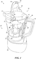
- FIGS. 1 and 2 depict perspective views of a blender system 10 according to an example embodiment of the present invention.
- the blender system 10 includes a container 12 adapted (e.g., sized and dimensioned) to receive food products to be processed.
- the blender system 10 can be adapted to perform any food processing or blending, including, as non-limiting examples, dicing, chopping, cutting, slicing, mixing, blending, stirring, crushing, or the like.
- the container 12 generally includes a bottom section 14, a top section 16, and one or more waiis 18 extending between the bottom section 14 and the top section 16.
- the one or more walls 18 define an interior volume of space forming a work chamber 20, within which food products are placed and processed.
- the bottom section 14 is generally closed as depicted in the example embodiment if FIGS. 1 and 2 , such that food products contained in the work chamber 20 are unable to escape the container 12 through the bottom section 14.
- a rotatable blade assembly 24 Disposed within the work chamber 20 is a rotatable blade assembly 24 adapted to facilitate processing and/or blending of food products.
- the container 12 can include a handle 26 for facilitating transportation and manipulation of the container 12.
- the blender system 10 can also include a base 30 configured (e.g., sized, shaped, and arranged) to receive and couple with the container 12.
- the base 30 can include a housing 31 a motorized unit (not visible in FIGS. 1 and 2 ) contained within the housing.
- the base 30 can be adapted to couple with the container 12 in such a way that the motorized unit and the rotatable blade assembly 24 become mechanically coupled, and the motorized unit can be adapted to drive rotation of the rotatable blade assembly 24 once mechanically coupled thereto, as would be appreciated by those of skill in the art.
- the container 12 can include a slidable actuator shaft 28 extending between the bottom section 14 and the top section 16 and configured to slide between a first position and a second position.
- the first and second positions are characterized by different relative heights of the slidable actuator shaft 28 (as oriented in FIGS. 1 and 2 ). More specifically, when in the first position, the slidable actuator shaft 28 of the example embodiment of FIGS. 1 and 2 is disposed at a relatively higher position (in relation to the top and bottom sections 14, 16 of the container 12) than when in the section position.
- moving the slidable actuator shaft 28 into the second position from the first position causes the slidable actuator shaft 28 to be lowered away from the top section 16 of the container 12.
- this lowering movement of the slidable actuator shaft 28 can cause an end portion of the slidable actuator shaft 28 to engage and activate the motorized unit in the base 30 to drive rotation of the rotatable blade assembly 24.
- this lowering movement of the slidable actuator shaft 28 causes an end portion of the slidable actuator shaft 28 to extend beyond the edge of the bottom section 14 of the container 12 and press against a mechanical switch on the motorized unit.
- the slidable actuator shaft 28 can be housed in a compartment coupled to the one or more walls 18, and the compartment can be at least partially open on its bottom end, e.g., to allow the end portion of the slidable actuator shaft 28 to pass therethrough.
- the blender system 10 can include a lid 32 sized and dimensioned to cover the opening 22 at the top section 16 of the container 12.
- the lid 32 can include a pour spout 34, as illustrated in FIGS. 1 and 2 .
- the lid 32 additionally can include a hinged actuator lever 36 adapted to engage the slidable actuator shaft 28 of the container 12.
- the hinged actuator lever 36 is movable between (a) a first position in which the slidable actuator shaft 28 is not engaged (e.g., an upright position, as depicted in FIGS. 1 and 2 ) and (b) a second position in which the slidable actuator shaft 28 is engaged (e.g., a flat position, as depicted in FIG. 5 ).
- engaging the slidable actuator shaft 28 activates the motorized unit in the base 30, as described in greater detail herein.
- the hinged actuator lever 36 can include at least one locking tab 38 (e.g., two are included in the example embodiment of FIGS. 1 and 2 ) that is sized, dimensioned, and orientated to engage with a keeper 40 disposed in the top section 16 of the container 12 (e.g., and extending from the one or more walls 18 of the container 12). More specifically, the locking tab 38 is adapted to engage with the keeper 40 to mechanically lock the lid 32 to the container 12 when the hinged actuator lever 36 is pivoted from the first position to the second position.
- a locking tab 38 e.g., two are included in the example embodiment of FIGS. 1 and 2
- the locking tab 38 is adapted to engage with the keeper 40 to mechanically lock the lid 32 to the container 12 when the hinged actuator lever 36 is pivoted from the first position to the second position.
- the keeper 40 can be shaped as a semi-circular track protruding from an exterior side of the one or more walls 18, and the locking tab 38 can be shaped as a corresponding semi-circular protrusion that slides beneath the keeper 40 and presses up against the keeper 40 when the hinged actuator lever 36 is moved into the second position.
- the combined locking effect of the locking tab 38 and the keeper 40 prevents the lid 32 from lifting up and becoming removed from the container 12 when the hinged actuator lever 36 is in the second position and the motorized unit is driving rotation of the rotatable blade assembly 24.
- the lid 32 also can include detent 39 extending from the hinged actuator lever 36.
- the detent 39 can be sized and positioned to engage the slidable actuator shaft 28 of the container 12 and to cause the slidable actuator shaft 28 to move from its first position to its second position.
- the lid 32 can include an aperture 42 disposed therein and therethrough.
- the container 12 likewise can include an aperture 46 disposed therein and therethrough.
- the aperture 46 in the container 12 can lead directly to a compartment housing the slidable actuator shaft 28. Furthermore, when the lid 32 is properly coupled to the container 12, the apertures 42, 46 are aligned and overlapping.
- the detent 39 can be sized and positioned on the hinged actuator lever 36 in such a way that moving the hinged actuator lever 36 into the second position causes the detent 39 to pass through the apertures 42, 46 and to press down on the slidable actuator shaft 28.
- a user controlling the hinged actuator lever 36 is able to cause the slidable actuator shaft 28 to move into the second position, thereby triggering the motorized unit to drive rotation of the rotatable blade assembly 24.
- One or more spring-loaded pins 44 can be disposed on and can extend from the hinged actuator lever 36.
- the spring-loaded pins 44 When the hinged actuator lever 36 is in the first position and the detent 39 is not engaging the slidable actuator shaft 28, the spring-loaded pins 44 are in a natural, uncompressed and non-retracted position.
- the hinged actuator lever 36 When the hinged actuator lever 36 is moved into the second position, the spring-loaded pins 44 are caused to press against a surface of the lid 32 and, as a result, retract. This generates a spring force in the spring-loaded pins 44, which tends to push the hinged actuator lever 36 out of the second position, absent the force applied by the user to the hinged actuator lever 36.
- the user for a user to maintain the hinged actuator lever 36 in the second position (during which time the rotatable blade assembly 24 is spinning) the user must apply and maintain a force against the hinged actuator lever 36.
- This can be beneficial, for example, in preventing unwanted or accidental activation of the rotatable blade assembly 24 due to a user forgetting or inadvertently failing to move the hinged actuator lever 36 from the second position back into the first position.
- the one or more spring-loaded pins 44 can be positioned on the flat surface of the lid 32 which receives the hinged actuator lever 36, as would be appreciated by one of skill in the art upon reading the present specification.
- the spring-loaded pins 44 are not included in the lid 32.
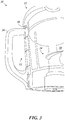
- FIG. 3 depicts a side view of the container 12 with the lid 32 disposed thereon with the slidable actuator shaft 28 and hinged actuator lever 36 in their respective first positions.
- the slidable actuator shaft 28 does not extend beyond the bottom edge of the container 12 when the slidable actuator shaft 28 is in its first position. Accordingly, the slidable actuator shaft 28 can be spring-loaded to naturally remain in the first position (e.g., can remain in the first position in the absence of a downward force on the slidable actuator shaft 28 that is larger than the force of the spring system maintaining the slidable actuator shaft 28 in the first position).
- a spring force is applied to the slidable actuator shaft 28 which tends to push the slidable actuator shaft 28 generally toward the first position. Accordingly, to overcome the spring force and maintain the slidable actuator shaft 28 in the second position, a user may press down against the hinged actuator lever 36 with a force that is greater than the spring force applied to the slidable actuator shaft 28.
- FIG. 4 and 5 show side views of the container 12 with the lid 32 disposed thereon and the slidable actuator shaft 28 and hinged actuator lever 36 in their respective second positions.
- a user can maintain the hinged actuator lever 36 in its second position by applying a pressure against the hinged actuator lever 36.
- This causes the hinged actuator lever 36 to engage with and press down upon the slidable actuator shaft 28.
- the slidable actuator shaft 28, as a result is moved into its second position, causing an end portion 48 thereof to extend beyond the bottom edge of the container 12, thereby enabling it to activate the motorized unit.
- the hinged actuator lever 36 is pivoted away from its second position back toward its first position, the detent 39 no longer intersects with the slidable actuator shaft 28 and the spring force is sufficient in quantity to return the slidable actuator shaft 28 to its first position.
- the motorized unit in the base 30 includes a mechanical switch that is adapted to be depressed by the end portion 48 of the slidable actuator shaft 28 when the slidable actuator shaft 28 is in the second position.
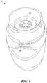
- FIG. 6 depicts a perspective view of the base 30 of the blender system 10 including such a mechanical switch 50.
- the switch 50 is positioned to be directly beneath the slidable actuator shaft 28 when the container 12 is coupled to the base 30.
- the switch 50 of the motorized unit is directly exposed to the slidable actuator shaft 28.
- the base 30 can also include a gear unit 51 surrounded by a cylindrical wall 55 forming a volume of space adapted to receive the container 12 (e.g., or some portion thereof or constituent component coupled thereto).
- the gear unit 51 is coupled, within the base, to the motorized unit.
- the gear unit 51 further is adapted to mechanically couple with the rotatable blade assembly 24 when the container 12 is coupled with the base 30, as would be appreciated by one of skill in the art upon reading the present specification. This mechanical coupling between the gear unit 51 and the rotatable blade assembly 24 enables the motorized unit to drive rotation of the rotatable blade assembly 24, e.g., by way of the gear unit 51.
- the base 30 optionally can also include a plurality of recesses (not shown) for receiving longitudinal tabs (not shown) disposed along the length of the container 12, as would be appreciated by one of skill in the art upon reading the present specification.
- the longitudinal tabs (not shown) may function as guides to ensure that the container 12 is complementarily and properly received by the base 30.
- the switch 50 can include a portion that extends upward into a compartment housing the slidable actuator shaft 28. In such alternative embodiments, activation of the motorized unit does not require that the end portion 48 of the slidable actuator shaft 28 extend beyond the bottom edge of the container 12 when the slidable actuator shaft 28 is in the second position.
- pulsed processing of food products may occur by periodic or intermittent control and manipulation of the hinged actuator lever 36.
- an external lock (not shown) may be included adjacent the hinged actuator lever 36 of the lid 32 to restrict the blender system 10 to continuous, non-intermittent operation.
- the rotatable blade assembly 24 can be any suitable or conventional blade assembly, as would be appreciated by one of skill in the art.
- the rotatable blade assembly 24 can be implemented using a novel rotatable blade assembly 24', which will now be described with reference to FIGS. 7A through 10 .
- the novel rotatable blade assembly 24' is described herein with reference to operation with and inclusion in the illustrative blender system 10 of FIGS. 1 and 2 , it should be understood that the rotatable blade assembly 24' alternatively can be a stand-alone device and/or can be included in other any conventional or suitable blender assembly not described or depicted herein.
- the rotatable blade assembly 24' is not limited to use or inclusion with the illustrative blender system 10 of FIGS. 1 and 2 , or with any other blender assembly.
- FIGS. 7A and 7B depict perspective views of a hub 52 supporting a rotatable blade assembly 24' in accordance with a further illustrative embodiment of the present invention.
- the hub 52 is a generally cylindrical axle.
- the hub 52 alternatively may be implemented using any other suitable shape and/or structure (e.g., conical, etc.).
- the hub 52 has a central axis 57 about which the rotatable blade assembly 24' is adapted to rotate.
- the hub 52 extends upward from a foundation 53 adapted to couple with the container 12 at the bottom section 14, e.g., by screwing onto the bottom section 14.
- the foundation 53 may include interior threads 72 enabling the foundation 53 to be screwed onto the bottom section 14 of the container 12.
- the foundation 53 may include a gasket (not shown) adjacent the interior threads 72 to ensure that a substantially complete seal is formed when the foundation 53 is coupled to the container 12.
- the rotatable blade assembly 24' generally includes a plurality of cutting blades 54a-d extending radially outward from the hub 52.
- Each of the cutting blades 54a-d has a sharp cutting edge 56, a blunt spine edge 58, and a cutting blade face 60 therebetween.
- two or more of the cutting blades 54a-d may be included in pairs.
- one or more of the cutting blades 54a-d generally can extend both radially outward from the hub 52 and longitudinally upward or longitudinally downward along the hub 52. For example, in accordance with the embodiment of FIGS.
- the cutting blades 54a-d can include a first pair of opposing cutting blades 54a, 54b extending radially outward from the hub 52 and longitudinally downward along the hub 52, as well as a second pair of opposing cutting blades 54c, 54d extending radially outward from the hub 52 and longitudinally upward along the hub 52.
- the first pair of opposing cutting blades 54a, 54b are "opposing” in that they are disposed around the hub 52 separated by an angular displacement of about 180 degrees.
- the second pair of opposing cutting blades 54c, 54d likewise are "opposing” in that they are disposed around the hub 52 separated by an angular displacement of about 180 degrees.
- the first pair of opposing cutting blades 54a, 54b and the second pairs of opposing cutting blades 54c, 54d are disposed around the hub 52 separated from each other by an angular displacement of about 90 degrees.
- any other number of cutting blades 54a-d e.g., one, two, three, five, six, etc.
- the cutting blades 54a-d are generally separated by about 90 degree increments in the example embodiment of FIGS. 7A and 7B
- the cutting blades 54a-d alternatively can be separated by any other suitable amount(s), which may be a uniform or variable amount among the plurality of cutting blades 54a-d.
- the rotatable blade assembly 24' includes at least one crushing blade 62 extending longitudinally outwardly from the hub 52 (e.g., vertically upward, as oriented in FIGS. 7A and 7B ).
- Each crushing blade 62 has a first edge 64, a second edge 66, and a crushing blade face 68 therebetween.
- two crushing blades 62 are disposed around the hub 52 separated by an angular displacement of about 90 degrees. The two crushing blades 62 are substantially parallel to each other, as depicted.
- each crushing blade 62 can be substantially flat and can be oriented to be substantially perpendicular to a tangent line drawn from the central axis 57 to the point halfway between the first and second edges 64, 66, as depicted in FIGS. 7A and 7B .
- Each of the crushing blades 62 can have a top edge that is sloped (e.g., by 45 degrees, or any other amount) relative to a plane containing a direction of rotation of the rotatable blade assembly 24'. It should be noted that the first edge 64 and second edge 66 represent smaller dimensions of the blade, while the crushing blade face 68 is a relatively substantially greater dimension, as would be interpreted in accordance with the customary labels for these parts of a knife blade or similar structure.
- the hub 52 can be adapted to rotate a first direction (e.g., clockwise) as well as a second direction opposite the first direction (e.g., counterclockwise).
- first direction e.g., clockwise
- second direction opposite the first direction
- first direction is referred to as being clockwise
- first direction alternatively can be counterclockwise
- second direction alternatively can be clockwise.
- the cutting blades 54 are all oriented in such a way that when the hub 52 rotates in the first directions (e.g., clockwise), the sharp cutting edge 56 of each cutting blade 54 is a leading surface and the blunt spine edge 58 of each cutting blade 54 is a trailing surface. Further due to this illustrative orientation of the cutting blades 54, when the hub 52 rotates in the second direction (e.g., counterclockwise), the blunt spine edge 58 of each cutting blade 54 is a leading surface and the sharp cutting edge 56 of each cutting blade 54 is a trailing surface.
- a “leading surface,” as used herein, generally refers to a surface of an object that is first to be impacted (e.g., by food products contained in the work chamber 20) during rotation of the object in a manner tending to crush the food product.
- a “trailing surface” generally refers a surface opposite or following the leading surface as it moves.
- a “surface” can be either a narrow edge, or can be a wider face, of the blade structure.
- Each crushing blade 62 can be oriented in such a way that its crushing blade face 68 is a leading surface when the hub 52 rotates in the first direction (e.g., clockwise) and a trailing surface when the hub 52 rotates in the second of the two opposite directions (e.g., counterclockwise).
- FIG. 8 depicts a top view of the crushing blades 62.
- the rearward portion of the crushing blade 62 e.g., relative to the direction of motion
- the frontward portion of the crushing blades 62 (e.g., relative to the direction of motion), which is opposite and follows behind the rearward portion, is a trailing surface.
- the crushing blades 62 extend longitudinally outwardly from the hub 52 (that is, longitudinal being a direction generally parallel to the central axis 57 about which the hub 52 rotates), food products contacting the crushing blades 62 during rotation of the hub 52 will be struck by the rearward half (relative to the direction of rotation) of the crushing blades 62, e.g., the leading surface as depicted in FIG. 8 .
- the food products will experience a blunt force exerted by the, e.g., substantially flat crushing blade face 68 which will tend to break up (e.g., crush) the impacted food products.
- one, some, or all of the cutting blades 54a - 54d can each optionally have some curvature in the respective cutting blade face 60 (e.g., may curve longitudinally downward or upward).
- the curvature can be useful, for example, in generating a sphere-like mixing effect.
- the cutting blade 54a can have a first radius of curvature and the opposing cutting blade 54b has a second radius of curvature; and the second radius of curvature of the opposing cutting blade 54b can be smaller than, greater than, or equal to the first radius of curvature.
- the cutting blade 54c can have a third radius of curvature and the opposing cutting blade 54d can have a fourth radius of curvature; and the fourth radius of curvature may be greater than, less than, or equal to the third radius of curvature.
- each of the cutting blades 54a-d can extend both radially outward from the hub 52 and longitudinally upward or longitudinally downward along the hub 52, each of the cutting blades 54a-d can be disposed at an angle relative to a plane containing the direction of rotation of the hub 52 (e.g., relative to the horizontal, as oriented in FIGS. 9 and 10 ).
- the cutting blades 54a, 54b can be disposed at an angle ⁇ away from a plane containing (a) a direction of rotation of the hub 52, (b) the point of connection between the hub 52 and the cutting blade 54a, and (c) the point of connection between the hub 52 and the cutting blade 54b.
- the angle ⁇ thus indicates the slope in the cutting blades 54a, 54b and generally can be about 45 degrees, or any other suitable angle (e.g., greater or less than 45 degrees). Furthermore, the cutting blades 54a, 54b need not be sloped at the same angle ⁇ as each other. Similarly, the cutting blades 54c, 54d can be disposed at an angle ⁇ away from a plane containing (a) a direction of rotation of the hub 52, (b) the point of connection between the hub 52 and the cutting blade 52c, and (c) the point of connection between the hub 52 and the cutting blade 52d. The angle ⁇ thus indicates the slope in the cutting blades 54c, 54d relative to the plane containing a direction of rotation of the hub 52. The angle ⁇ generally can be about 45 degrees, or any other suitable angle (e.g., greater or less than 45 degrees). Furthermore, the cutting blades 54c, 54d need not be sloped at the same angle ⁇ as each other.
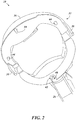
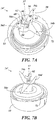
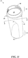
- FIG. 11 depicts an example embodiment of the container 12 adapted for use with the rotatable blade assembly 24' of FIGS. 7A, 7B and 8 .
- FIG. 12 further depicts a view of the container 12 of FIG. 11 looking down on the bottom section 14 from line B-B in FIG. 11 .
- the container 12 can include interior threads 80 formed in the top section 16, for enabling the container 12 to couple with the lid 32.
- the container 12 can include interior threads (not shown) formed in the bottom section 14 of the container, for enabling the container 12 to couple with the foundation 53 by mating with the interior threads 72 of the foundation 53.
- the interior threads 80 are shown, it should be appreciated that exterior threads, or any other suitable coupling mechanism, alternatively or additionally may be included to enable coupling between the container 12 and the foundation 53.
- the container 12 optionally may include a plurality of ledge surface features 76 adapted to facilitate the processing of food products.
- the plurality of ledge surface features 76 may extend from an interior face of the bottom section 14 inward toward a center of the bottom section 14.
- the ledge surface features 76 can be sized, dimensioned, and oriented, in such a way as to hinder vortex formation by food contents within the work chamber 20 during a blending operation.
- each of the plurality of ledge surface features 76 can include a surface that curves inward and which has a decreasing radius of curvature as measured from a center point 87 of the bottom section 14.
- Each of the plurality of ledge surface features 76 additionally can terminate in an abrupt ledge 77, at which point the surface extends from an interior face of the bottom section 14 radially inward toward the center 87 of the bottom section 14, e.g., to form a corner jutting into the work chamber 20.
- vortexes increase the likelihood of at least some food products bypassing the food processing functions of the blender system 10, e.g., by becoming lodged away or stuck near the outer perimeter of the vortex away from the rotatable blade assembly 24.
- the interior of the container 12 may include a plurality of ribs (not shown) adapted to facilitate the processing of food products in the work chamber 20 similarly by disrupting the formation or the presence of vortexes within the work chamber during operation of the rotatable blade assembly 24.
- the foundation 53 further can be adapted to couple with the base 30, as will now be described.
- the underside of the foundation 53 generally may be sized and shaped to fit securely within the volume of space defined by the cylindrical wall 55 of the base 30.
- the foundation 53 additionally may include a gear unit adapted to drive rotation of the rotatable blade assembly 24'.
- the gear unit can be coupled to the rotatable blade assembly 24' by one or more interior axles, rods, etc.
- the gear unit further can be adapted to mechanically couple with the gear unit 51 of the base 30, e.g., and can engage with the gear unit 51 of the base 30 once the bottom section 14 of the container 12 with the foundation 53 included therein is placed onto the base 30. Accordingly, rotation of the gear unit 51 of the base 30 can cause the gear unit of the foundation 53 to rotate, thereby causing the rotatable blade assembly 24' to rotate.
Landscapes
- Engineering & Computer Science (AREA)
- Food Science & Technology (AREA)
- Chemical & Material Sciences (AREA)
- Chemical Kinetics & Catalysis (AREA)
- Mechanical Engineering (AREA)
- Food-Manufacturing Devices (AREA)
- Crushing And Pulverization Processes (AREA)
Claims (16)
- Klingenanordnung (24') für einen Mixer, wobei die Klingenanordnung (24') Folgendes umfasst:eine Nabe (52) mit einer Mittelachse (57), um die sich die Klingenanordnung (24') dreht;eine Vielzahl von Schneidklingen (54a-d), die sich von der Nabe (52) radial nach außen erstrecken, wobei jede der Schneidklingen (54a-d) eine scharfe Schneidkante (56), eine stumpfe Rückenschneide (58) und eine Schneidklingenfläche (60) dazwischen hat;mindestens eine Zerkleinerungsklinge (62), die sich von der Nabe (52) längs nach außen erstreckt, wobei die mindestens eine Zerkleinerungsklinge eine erste Kante (64), eine zweite Kante (66) und eine Zerkleinerungsklingenfläche (68) dazwischen hat;wobei die Vielzahl von Schneidklingen (54a-d), die auf solche Weise ausgerichtet sind, um zu verursachen, dass die scharfe Schneidkante (56) jeder Klinge eine führende Oberfläche ist und die stumpfe Rückenschneide (58) eine nachlaufende Oberfläche ist, wenn sich die Nabe (52) in eine erste Richtung dreht, und dass die stumpfe Rückenschneide (58) jeder Klinge eine führende Oberfläche ist und die scharfe Schneidkante (56) eine nachlaufende Oberfläche ist, wenn sich die Nabe (52) in eine zweite Richtung dreht, die der ersten Richtung entgegengesetzt ist; und dadurch gekennzeichnet, dass:die mindestens eine Zerkleinerungsklinge (62) auf solche Weise ausgerichtet ist, um zu verursachen, dass die Zerkleinerungsklingenfläche (68) eine führende Oberfläche ist, wenn sich die Nabe (52) in die erste Richtung dreht, und eine nachlaufende Oberfläche ist, wenn sich die Nabe (52) in die zweite Richtung dreht; undsich die mindestens eine Zerkleinerungsklinge (62) vertikal nach oben in eine Richtung erstreckt, die im Allgemeinen parallel zu der Mittelachse (57) ist.
- Klingenanordnung nach Anspruch 1, wobei jede scharfe Schneidkante (56) schärfer als jede stumpfe Rückenschneide (58) ist.
- Klingenanordnung nach Anspruch 1, wobei die scharfe Schneidkante (56) einer ersten aus der Vielzahl von Schneidklingen einen ersten Krümmungsradius hat und die scharfe Schneidkante (56) einer zweiten aus der Vielzahl von Schneidklingen einen zweiten Krümmungsradius hat, wobei der zweite Krümmungsradius kleiner als der erste Krümmungsradius ist.
- Klingenanordnung nach Anspruch 3, wobei die scharfe Schneidkante (56) einer dritten aus der Vielzahl von Schneidklingen einen dritten Krümmungsradius hat und die scharfe Schneidkante (56) einer vierten aus der Vielzahl von Schneidklingen einen vierten Krümmungsradius hat, wobei der vierte Krümmungsradius kleiner als der dritte Krümmungsradius ist.
- Klingenanordnung nach Anspruch 1, wobei die Klingenanordnung betriebsfähig ist, um Lebensmittel mit der führenden Oberfläche der mindestens einen Zerkleinerungsklinge (62) zu zerkleinern, wenn sich die Nabe (52) um die Mittelachse dreht.
- Klingenanordnung nach Anspruch 1, wobei, wenn sich die Nabe (52) in eine erste Richtung dreht, die führende Oberfläche von mindestens einer aus der Vielzahl von Schneidklingen (54a-d) die scharfe Schneidkante (56) ist und die führende Oberfläche der mindestens einen Zerkleinerungsklinge (62) die Zerkleinerungsklingenfläche (68) ist.
- Klingenanordnung nach Anspruch 1, wobei, wenn sich die Nabe (52) in eine erste Richtung dreht, die führende Oberfläche von mindestens einer aus der Vielzahl von Schneidklingen (54a-d) die stumpfe Rückenschneide (58) ist und die führende Oberfläche der mindestens einen Zerkleinerungsklinge (62) die Zerkleinerungsklingenfläche (68) ist.
- Mixerbehälter (12), umfassend:ein Unterteil (14); undeine oder mehrere Behälterwände (18), die sich von dem Unterteil (14) nach oben erstrecken und ein Innenvolumen von Raum definieren, der eine Arbeitskammer (20) zum Verarbeiten von einem oder mehreren Lebensmitteln bildet, wobei die eine oder mehreren Wände (18) an einem Oberteil (16) enden, das dem Unterteil (14) gegenüberliegt, und eine Öffnung (22) haben, die einen Zugang zu der Arbeitskammer (22) bereitstellt;wobei die eine oder mehreren Behälterwände (18) eine Vielzahl von Vorsprungsflächenelementen (76) beinhalten, deren Größe, Ausmaße und Ausrichtung auf solche Weise sind, um eine Wirbelbildung durch Lebensmittelinhalte in der Arbeitskammer (20) während eines Mischvorgangs zu verhindern;eine Klingenanordnung nach einem der vorhergehenden Ansprüche.
- Mixerbehälter (12) nach Anspruch 8, wobei jedes der Vorsprungsflächenelemente (76) eine Oberfläche umfasst, die einen abnehmenden Krümmungsradius hat, gemessen von einem Mittelpunkt (87) im Unterteil (14) des Behälters (12), die in einem plötzlichen Vorsprung (77) endet, wobei die Oberfläche eine Ecke bildet und sich von dem Mittelpunkt (87) in eine radiale Richtung nach außen erstreckt.
- Mixerbehälter nach Anspruch 8, ferner umfassend einen Deckel (32), dessen Größe und Ausmaße so sind, um die Öffnung (22) in dem Oberteil (16) abzudecken, wenn er auf dem Behälter (12) positioniert ist.
- Mixersystem (10), umfassend:einen Mixerbehälter (12), umfassend:ein Unterteil (14); undeine oder mehrere Behälterwände (18), die sich von dem Unterteil (14) nach oben erstrecken und ein Innenvolumen von Raum definieren, der eine Arbeitskammer (20) zum Verarbeiten von einem oder mehreren Lebensmitteln bildet, wobei die eine oder mehreren Wände (18) an einem Oberteil (16) enden, das dem Unterteil (14) gegenüberliegt, und eine Öffnung (22) haben, die einen Zugang zu der Arbeitskammer (20) bereitstellt;wobei die eine oder mehreren Behälterwände (18) eine Vielzahl von Vorsprungsflächenelementen (76) beinhalten, deren Größe, Ausmaße und Ausrichtung so sind, um eine Wirbelbildung durch Lebensmittelinhalte in der Arbeitskammer (20) während einem Mischvorgang zu verhindern; undeine Klingenanordnung (24'), umfassend:eine Nabe (52) mit einer Mittelachse (57), um die sich die Klingenanordnung (24') dreht;eine Vielzahl von Schneidklingen (54a-d), die sich radial nach außen von der Nabe (52) erstrecken, wobei jede der Schneidklingen (54a-d) eine scharfe Schneidkante (56), eine stumpfe Rückenschneide (58) und eine Schneidklingenfläche (60) dazwischen hat;mindestens eine Zerkleinerungsklinge (62), die sich von der Nabe (52) längs nach außen erstreckt, wobei die mindestens eine Zerkleinerungsklinge (62) eine erste Kante (64), eine zweite Kante (66) und eine Zerkleinerungsklingenfläche (68) dazwischen hat;wobei die Vielzahl von Schneidklingen (54a-d), die auf solche Weise ausgerichtet sind, um zu verursachen, dass die scharfe Schneidkante (56) jeder Klinge eine führende Oberfläche ist und die stumpfe Rückenschneide (58) eine nachlaufende Oberfläche ist, wenn sich die Nabe (52) in eine erste Richtung dreht, und dass die stumpfe Rückenschneide (58) jeder Klinge eine führende Oberfläche ist und die scharfe Schneidkante (56) eine nachlaufende Oberfläche ist, wenn sich die Nabe (52) in eine zweite Richtung dreht, die der ersten Richtung entgegengesetzt ist; unddie mindestens eine Zerkleinerungsklinge (62) auf solche Weise ausgerichtet ist, um zu verursachen, dass die Zerkleinerungsklingenfläche (68) eine führende Oberfläche ist, wenn sich die Nabe (52) in die erste Richtung dreht, und eine nachlaufende Oberfläche ist, wenn sich die Nabe (52) in die zweite Richtung dreht;wobei sich die mindestens eine Zerkleinerungsklinge (62) vertikal nach oben in eine Richtung erstreckt, die im Allgemeinen parallel zu der Mittelachse (57) ist.
- Mixersystem nach Anspruch 11, ferner umfassend:
eine motorisierte Einheit, die in einer Basis (30) angeordnet ist, die konfiguriert ist, um den Behälter (12) auf solche Weise aufzunehmen und an diesen zu koppeln, um die motorisierte Einheit mit der Nabe (52) der Klingenanordnung (24') mechanisch zu koppeln, um der Klingenanordnung (24') Rotationsenergie zuzuführen. - Mixersystem nach Anspruch 11, ferner umfassend:eine Halterung (40), die in dem Oberteil (16) des Mixerbehälters (12) angeordnet ist; undeine verschiebbare Antriebswelle (28), die sich zwischen dem Unterteil (14) und dem Oberteil (16) des Mixerbehälters (12) erstreckt und konfiguriert ist, um sich zwischen einer ersten Position und einer zweiten Position zu verschieben;einen Deckel (32), dessen Größe und Ausmaße so sind, um die Öffnung (22) in dem Oberteil (16) abzudecken, wenn er auf dem Behälter (12) positioniert ist, wobei der Deckel (32) Folgendes umfasst:einen klappbaren Betätigungshebel (36) mit mindestens einer Verriegelungslasche (38), deren Größe, Ausmaße und Ausrichtung so sind, um mit der Halterung (40) in Eingriff zu sein, um den Deckel (32) an den Behälter (12) mechanisch zu verriegeln, wenn er von einer ersten Position zu einer zweiten Position geschwenkt wird;eine Arretierung (39), die in dem klappbaren Betätigungshebel (36) angeordnet ist und deren Größe, Ausmaße und Ausrichtung so sind, um sich mit der verschiebbaren Antriebswelle (28) des Behälters (12) zu überschneiden, wenn der Deckel (32) auf dem Behälter (12) positioniert ist und der klappbare Betätigungshebel (36) zu der zweiten Position geschwenkt ist; undeine motorisierte Einheit, die in einer Basis (30) angeordnet ist, die konfiguriert ist, um den Behälter (12) auf solche Weise aufzunehmen und an diesen zu koppeln, um die motorisierte Einheit mit der Klingenanordnung (24') mechanisch zu koppeln, um dieser Rotationsenergie zuzuführen, wobei die motorisierte Einheit durch einen mechanischen Schalter (50) aktiviert wird;wobei, wenn sich die Arretierung (39) des Deckels (32) mit der verschiebbaren Antriebswelle (28) des Behälters überschneidet, sich die verschiebbare Antriebswelle von der ersten Position zu der zweiten Position auf solche Weise verschiebt, um sich mit dem mechanischen Schalter (50) mechanisch zu schneiden und diesen von einer Aus-Position zu einer An-Position zu bewegen, wodurch die motorisierte Einheit aktiviert wird und verursacht wird, dass sich die Klingenanordnung (24') dreht.
- Mixersystem nach Anspruch 13, wobei die verschiebbare Antriebswelle (28) eine Federkraft hat, die darauf ausgeübt wird, wodurch die verschiebbare Antriebswelle (28) im Allgemeinen zu der ersten Position gedrückt wird.
- Mixersystem nach Anspruch 14, wobei eine Kraft, die durch die Arretierung (39) gegen die verschiebbare Antriebswelle (28) ausgeübt wird, in ihrer Menge ausreichend ist, um die Federkraft zu überwinden und zu verursachen, dass sich die verschiebbare Antriebswelle (28) von der ersten Position zu der zweiten Position bewegt.
- Mixersystem nach Anspruch 14, wobei ferner, wenn der klappbare Betätigungshebel (36) weg von der zweiten Position zu der ersten Position geschwenkt wird, die Arretierung (39) sich nicht mehr mit der verschiebbaren Antriebswelle (28) überschneidet und die Federkraft in ihrer Menge ausreichend ist, um die verschiebbare Antriebswelle (28) zu der ersten Position zurückzuführen.
Applications Claiming Priority (3)
| Application Number | Priority Date | Filing Date | Title |
|---|---|---|---|
| US201161511614P | 2011-07-26 | 2011-07-26 | |
| US201161526398P | 2011-08-23 | 2011-08-23 | |
| PCT/US2012/048339 WO2013016533A1 (en) | 2011-07-26 | 2012-07-26 | Blender system and rotatable blade assembly |
Publications (3)
| Publication Number | Publication Date |
|---|---|
| EP2736392A1 EP2736392A1 (de) | 2014-06-04 |
| EP2736392A4 EP2736392A4 (de) | 2016-05-18 |
| EP2736392B1 true EP2736392B1 (de) | 2019-06-05 |
Family
ID=47601538
Family Applications (1)
| Application Number | Title | Priority Date | Filing Date |
|---|---|---|---|
| EP12818069.2A Active EP2736392B1 (de) | 2011-07-26 | 2012-07-26 | Mischsystem und drehbare klingenanordnung |
Country Status (7)
| Country | Link |
|---|---|
| US (4) | US10064520B2 (de) |
| EP (1) | EP2736392B1 (de) |
| JP (2) | JP5985633B2 (de) |
| CN (1) | CN103957757B (de) |
| AU (1) | AU2012286803B2 (de) |
| CA (1) | CA2842832C (de) |
| WO (1) | WO2013016533A1 (de) |
Families Citing this family (34)
| Publication number | Priority date | Publication date | Assignee | Title |
|---|---|---|---|---|
| WO2012170821A1 (en) * | 2011-06-10 | 2012-12-13 | Euro-Pro Operating Llc | Blender |
| CN103957757B (zh) | 2011-07-26 | 2017-06-20 | 尚科宁家运营有限公司 | 混合系统和可旋转刀片组件 |
| US9814357B2 (en) | 2013-03-14 | 2017-11-14 | Spectrum Brands, Inc. | Container and blade arrangement for food preparation appliance |
| JP2016519632A (ja) * | 2013-03-15 | 2016-07-07 | シャークニンジャ オペレーティング エルエルシー | 容器蓋解放装置および方法 |
| US9198540B2 (en) * | 2013-08-02 | 2015-12-01 | Hamilton Beach Brands, Inc. | Food processor with locking bail handle |
| US9049967B1 (en) | 2014-08-08 | 2015-06-09 | Euro-Pro Operating Llc | Food processing apparatus and method |
| CN204379043U (zh) * | 2014-08-08 | 2015-06-10 | 优罗普洛运营有限责任公司 | 食品加工设备 |
| DE102014217241A1 (de) * | 2014-08-28 | 2016-03-03 | BSH Hausgeräte GmbH | Messeranordnung für ein Küchengerät sowie Küchengerät mit einer Messeranordnung |
| DE102015207196B3 (de) | 2015-04-21 | 2016-05-25 | De'longhi Braun Household Gmbh | Arbeitsgerät mit teleskopartig beweglichem Schaft zum Rühren oder Zerkleinern von Nahrungsmitteln |
| DE102015207197B3 (de) | 2015-04-21 | 2016-06-16 | De'longhi Braun Household Gmbh | Stabmixermesser mit Fräskante |
| JP6942638B2 (ja) | 2015-06-08 | 2021-09-29 | シャークニンジャ オペレーティング エルエルシー | 食品加工装置および方法 |
| FR3038241A1 (fr) * | 2015-07-03 | 2017-01-06 | Santos | Melangeur pour aliments |
| KR101717011B1 (ko) * | 2016-01-27 | 2017-03-27 | (주)제이월드텍 | 믹서복합장치 |
| GB2551162B (en) * | 2016-06-08 | 2022-03-09 | Kenwood Ltd | Detachable rib and stir tool for a mixing bowl |
| WO2017218952A1 (en) | 2016-06-16 | 2017-12-21 | Sigma Phase, Corp. | System for providing a single serving of a frozen confection |
| US20190274482A1 (en) * | 2016-12-13 | 2019-09-12 | Nestec S.A. | Ergonomic whisk for food processing |
| CN108324132B (zh) * | 2017-01-20 | 2022-02-01 | 广东美的生活电器制造有限公司 | 具有搅拌功能的料理机 |
| EP3589178A1 (de) * | 2017-04-17 | 2020-01-08 | Flama, Fábrica De Loucas E Electrodomésticos, Sa | Küchenmaschine mit verbessertem deckelgriff und verfahren zum betrieb davon |
| EP3691502B1 (de) * | 2017-10-02 | 2024-08-14 | Sunbeam Products, Inc. | Intelligenter mischer |
| KR101862587B1 (ko) * | 2017-12-17 | 2018-05-31 | 주식회사 라이프디테일 | 믹서기용 양방향 동시 회전 칼날 뭉치 |
| CN108078434B (zh) * | 2017-12-27 | 2024-07-19 | 深圳市品罗创新实业有限公司 | 一种搅拌器 |
| GR1009532B (el) * | 2018-05-03 | 2019-05-23 | ΣΩΚΡΑΤΗΣ Δ. ΚΩΝΣΤΑΝΤΙΝΟΥ ΚΑΙ ΥΙΟΣ Α.Ε. ΕΜΠΟΡΙΟ-ΒΙΟΜΗΧΑΝΙΑ ΥΑΛΙΚΩΝ ΚΑΙ ΕΙΔΩΝ ΟΙΚΙΑΚΗΣ ΧΡΗΣΗΣ με Δ.Τ. "YALCO" | Πολυκοφτης με στομιο υποδοχης υγρων εν λειτουργια |
| US11470855B2 (en) | 2018-08-17 | 2022-10-18 | Coldsnap, Corp. | Providing single servings of cooled foods and drinks |
| US10543978B1 (en) | 2018-08-17 | 2020-01-28 | Sigma Phase, Corp. | Rapidly cooling food and drinks |
| US10612835B2 (en) | 2018-08-17 | 2020-04-07 | Sigma Phase, Corp. | Rapidly cooling food and drinks |
| CN111084565B (zh) * | 2018-10-23 | 2022-03-22 | 广东美的生活电器制造有限公司 | 搅拌杯组件和食物料理机 |
| CN110117146A (zh) * | 2019-06-11 | 2019-08-13 | 杭州更蓝生物科技有限公司 | 便于送料的污泥脱水成型装置 |
| US11337438B2 (en) | 2020-01-15 | 2022-05-24 | Coldsnap, Corp. | Rapidly cooling food and drinks |
| TW202202790A (zh) | 2020-06-01 | 2022-01-16 | 美商寇德斯納普公司 | 用於快速冷卻食物及飲料的冷凍系統 |
| CN111685573B (zh) * | 2020-06-28 | 2021-06-04 | 浙江森菱电子科技有限公司 | 一种能调节刀片角度的榨汁机 |
| WO2022170323A1 (en) | 2021-02-02 | 2022-08-11 | Coldsnap, Corp. | Filling aluminum cans aseptically |
| KR20220140325A (ko) * | 2021-04-09 | 2022-10-18 | 엘지전자 주식회사 | 블렌더 |
| CN114985067B (zh) * | 2022-05-23 | 2023-05-23 | 申安娜 | 一种肚包肉制备用肉材绞肉设备及其使用方法 |
| CN116689457B (zh) * | 2023-06-21 | 2023-12-15 | 湖南省欧朗环保科技有限公司 | 一种餐余垃圾资源化处理装置 |
Family Cites Families (64)
| Publication number | Priority date | Publication date | Assignee | Title |
|---|---|---|---|---|
| US2284155A (en) * | 1939-04-27 | 1942-05-26 | Henry J Goldblatt | Food mixer |
| US2702571A (en) * | 1949-10-04 | 1955-02-22 | Pollard & Johnston | Magnetically actuated food stirring device |
| US2771111A (en) * | 1955-09-30 | 1956-11-20 | Scovill Manufacturing Co | Agitator and cutter unit for disintegrating food mixers |
| US3738583A (en) * | 1971-02-22 | 1973-06-12 | A Berland | Apparatus for mixing, blending, liquifying or chopping |
| US3892365A (en) * | 1971-07-23 | 1975-07-01 | Pierre Verdun | Apparatus for preparing food |
| JPS5534912Y2 (de) * | 1976-07-15 | 1980-08-18 | ||
| JPS5534912A (en) | 1978-09-01 | 1980-03-11 | Toppan Printing Co Ltd | Transcription sheet for polyamide |
| DE2817044C3 (de) * | 1978-04-19 | 1982-01-28 | Braun Ag, 6000 Frankfurt | Elektrischer Haushalts-Mischzerkleinerer |
| JPS5534912U (de) | 1978-08-30 | 1980-03-06 | ||
| US4216917A (en) * | 1978-11-13 | 1980-08-12 | Cuisinarts, Inc. | Safety interlock for the food pusher in a food processor |
| US4226373A (en) * | 1979-03-05 | 1980-10-07 | Wilson Research & Development, Inc. | Feed tube protector for a food processor |
| US4741482A (en) * | 1979-08-29 | 1988-05-03 | Robot-Coupe S.A. | Magnetic safety switch device for food processor |
| US4629131A (en) * | 1981-02-25 | 1986-12-16 | Cuisinarts, Inc. | Magnetic safety interlock for a food processor utilizing vertically oriented, quadrant coded magnets |
| JPS5985633U (ja) | 1982-11-29 | 1984-06-09 | トヨタ自動車株式会社 | プレス機のリフト装置 |
| US4506836A (en) * | 1982-12-20 | 1985-03-26 | Cuisinarts Research & Development, Inc. | Dual cover and feed tube protector actuation apparatus for a food processor |
| US4512522A (en) * | 1983-06-02 | 1985-04-23 | Cuisinarts, Inc. | Single vertical motion feedtube protector and actuator for a food processor |
| JPS6145052U (ja) * | 1984-08-25 | 1986-03-25 | 東芝テック株式会社 | 電気ミキサ− |
| US4691870A (en) * | 1984-10-09 | 1987-09-08 | Matsushita Electric Industrial Co. | Electric food processor |
| US4674690A (en) * | 1985-01-11 | 1987-06-23 | Kitchenaid, Inc. | Feed tube protector retaining apparatus |
| US4706896A (en) * | 1986-06-11 | 1987-11-17 | Chiaphua Industries Limited | Food processor |
| ES2005071A6 (es) * | 1986-09-11 | 1989-03-01 | Taurus Sa Com Ind | Perfeccionamientos en las herramientas de corte para electrobatidoras de mano |
| JPS63138078A (ja) | 1986-11-28 | 1988-06-10 | 株式会社フジクラ | 電柱支線の融雪装置 |
| US4824029A (en) * | 1988-01-07 | 1989-04-25 | Whirlpool Corporation | Child-lock for food processor |
| JPH0245278A (ja) | 1988-08-05 | 1990-02-15 | Nippon Spindle Mfg Co Ltd | トラクタに牽引されるトレーラのステアリング制御装置 |
| JP2571438B2 (ja) | 1989-06-20 | 1997-01-16 | 宇部興産株式会社 | 除麈装置 |
| JPH0321712U (de) | 1989-07-12 | 1991-03-05 | ||
| JPH0417820A (ja) | 1990-05-11 | 1992-01-22 | Matsushita Electric Ind Co Ltd | フードミキサー |
| JP3055261B2 (ja) | 1991-11-12 | 2000-06-26 | 松下電器産業株式会社 | タイマー装置 |
| FR2692463B1 (fr) * | 1992-06-17 | 1994-08-26 | Santos Sa | Appareil électrique pour le traitement de produits alimentaires, avec dispositif perfectionné de sécurité. |
| JPH0946772A (ja) | 1995-07-31 | 1997-02-14 | Rohm Co Ltd | 光学検知方法、それを用いた光学検知装置及びその光 学検知装置を搭載した電子機器 |
| JPH10192158A (ja) * | 1996-12-30 | 1998-07-28 | Sanyo Electric Co Ltd | ミキサー |
| JP3055261U (ja) | 1998-06-24 | 1999-01-12 | 株式会社三栄コーポレーション | 食品粉砕装置 |
| US6609821B2 (en) | 2001-04-13 | 2003-08-26 | Sunbeam Products, Inc. | Blender base with food processor capabilities |
| FR2824251B1 (fr) * | 2001-05-02 | 2003-06-27 | Hameur | Dispositif de securite pour un robot de cuisine a grande goulotte |
| US6666574B1 (en) * | 2002-06-03 | 2003-12-23 | Hamilton Beach/Proctor-Silex, Inc. | Blender blade assembly |
| US6986475B2 (en) * | 2003-06-10 | 2006-01-17 | Conair Corporation | Cover for food processor |
| US6907819B2 (en) * | 2003-07-01 | 2005-06-21 | Conair Corporation | Flip ramp mechanical interlock for appliance |
| US6960015B2 (en) * | 2003-11-07 | 2005-11-01 | Ming-Tsung Lee | Cutter stand of a mixer |
| GB2426868B (en) * | 2005-06-03 | 2008-01-09 | Kenwood Marks Ltd | Interlock system |
| CN101282672B (zh) | 2005-09-05 | 2014-09-24 | 布瑞威利私人有限公司 | 具有匹配的壶和刀片的搅拌机 |
| US7374117B2 (en) * | 2005-10-28 | 2008-05-20 | Kou-I Lin | Container of a blender |
| US7641380B2 (en) * | 2007-02-16 | 2010-01-05 | Sunbeam Products, Inc. | Blender/food processor blade arrangement for small throated blender jars |
| US7520453B2 (en) * | 2007-03-05 | 2009-04-21 | Hamilton Beach Brands, Inc. | Safety actuator for a food processor having a visual indication |
| US7581688B2 (en) * | 2007-03-12 | 2009-09-01 | Whirlpool Corporation | Blender with crushed ice functionality |
| ES2341821B1 (es) * | 2007-04-19 | 2011-04-08 | Electrodomesticos Taurus, S.L. | Util de corte y cabezal de trabajo para batidora electrica de varilla. |
| US20090260236A1 (en) * | 2008-04-16 | 2009-10-22 | Kuan-Chih Lin | Knife of a blender |
| US20100071219A1 (en) | 2008-09-22 | 2010-03-25 | Kuan-Chih Lin | Cutter of a juicer |
| KR20120104144A (ko) | 2009-06-24 | 2012-09-20 | 데이비드 메나쉬즈 | 음식물처리기용의 범용 커팅날과 액세서리 |
| CN201578095U (zh) * | 2009-11-19 | 2010-09-15 | 九阳股份有限公司 | 料理机用六叶刀具 |
| US9770135B2 (en) * | 2013-09-04 | 2017-09-26 | Breville Pty Ltd | Food processor with safety mechanism |
| WO2012075525A1 (en) * | 2010-12-07 | 2012-06-14 | Breville Pty Limited | Improved food processor |
| US8800905B2 (en) * | 2011-02-08 | 2014-08-12 | Main Power Electrical Factory Ltd. | Mixing vessel |
| US9010668B2 (en) * | 2011-06-30 | 2015-04-21 | Sammic, S.L. | Safety device for food cutting machine |
| CN103957757B (zh) | 2011-07-26 | 2017-06-20 | 尚科宁家运营有限公司 | 混合系统和可旋转刀片组件 |
| USD690159S1 (en) * | 2011-08-05 | 2013-09-24 | Euro-Pro Operating Llc | Blades |
| US8721165B2 (en) * | 2011-09-23 | 2014-05-13 | Whirlpool Corporation | Blender with varying internally and externally shaped container |
| US20130233952A1 (en) * | 2012-03-08 | 2013-09-12 | Hamilton Beach Brands, Inc. | Kitchen Appliance for Processing Foodstuff and Method of Operating Same |
| US9095238B2 (en) * | 2012-09-24 | 2015-08-04 | Wen Ching Lee | Container for a food mixer |
| USD709325S1 (en) * | 2013-01-29 | 2014-07-22 | Guangdong Xinbao Electrical Appliances Holdings Co., Ltd | Blade of blender |
| US9198540B2 (en) * | 2013-08-02 | 2015-12-01 | Hamilton Beach Brands, Inc. | Food processor with locking bail handle |
| USD783353S1 (en) * | 2015-05-21 | 2017-04-11 | Sharkninja Operating Llc | Blade assembly |
| US10610055B2 (en) * | 2016-09-21 | 2020-04-07 | Whirlpool Corporation | Food processor non-contact interlock |
| CN112312807B (zh) * | 2018-06-29 | 2024-09-03 | 布瑞威利私人有限公司 | 锁定机构 |
| AU2019295420A1 (en) * | 2018-06-29 | 2021-01-14 | Breville Pty Limited | Safety system, a method for selecting an operating mode, and a lid for a kitchen device |
-
2012
- 2012-07-26 CN CN201280044044.3A patent/CN103957757B/zh active Active
- 2012-07-26 CA CA2842832A patent/CA2842832C/en active Active
- 2012-07-26 AU AU2012286803A patent/AU2012286803B2/en active Active
- 2012-07-26 US US13/261,801 patent/US10064520B2/en active Active
- 2012-07-26 WO PCT/US2012/048339 patent/WO2013016533A1/en active Application Filing
- 2012-07-26 EP EP12818069.2A patent/EP2736392B1/de active Active
- 2012-07-26 JP JP2014523001A patent/JP5985633B2/ja active Active
-
2016
- 2016-03-25 JP JP2016061477A patent/JP2016165466A/ja active Pending
-
2018
- 2018-07-16 US US16/036,613 patent/US11166596B2/en active Active
-
2021
- 2021-04-09 US US17/226,729 patent/US11653793B2/en active Active
-
2023
- 2023-05-22 US US18/321,296 patent/US12171374B2/en active Active
Non-Patent Citations (1)
| Title |
|---|
| None * |
Also Published As
| Publication number | Publication date |
|---|---|
| JP2014523792A (ja) | 2014-09-18 |
| WO2013016533A1 (en) | 2013-01-31 |
| US10064520B2 (en) | 2018-09-04 |
| US20140231562A1 (en) | 2014-08-21 |
| US20230301466A1 (en) | 2023-09-28 |
| US11653793B2 (en) | 2023-05-23 |
| CA2842832C (en) | 2016-08-30 |
| EP2736392A4 (de) | 2016-05-18 |
| AU2012286803B2 (en) | 2015-11-19 |
| US20210219784A1 (en) | 2021-07-22 |
| US11166596B2 (en) | 2021-11-09 |
| CN103957757B (zh) | 2017-06-20 |
| US12171374B2 (en) | 2024-12-24 |
| AU2012286803A1 (en) | 2014-02-20 |
| JP5985633B2 (ja) | 2016-09-06 |
| EP2736392A1 (de) | 2014-06-04 |
| US20180317714A1 (en) | 2018-11-08 |
| JP2016165466A (ja) | 2016-09-15 |
| CA2842832A1 (en) | 2013-01-31 |
| CN103957757A (zh) | 2014-07-30 |
Similar Documents
| Publication | Publication Date | Title |
|---|---|---|
| US12171374B2 (en) | Blender system with rotatable blade assembly | |
| JP6272362B2 (ja) | 食品処理機 | |
| US8702300B2 (en) | Food processor and attachment | |
| US20120026827A1 (en) | Food processor with attachment | |
| EP3178358B1 (de) | Lebensmittelverarbeitungsvorrichtung und -verfahren | |
| ES2922768T3 (es) | Robot de cocina | |
| JP2010514480A (ja) | 食物処理システム | |
| EP2767203B1 (de) | Stabmixer | |
| EP3766394B1 (de) | Behälter für ein küchengerät | |
| JP3795471B2 (ja) | ミキサーおよびミキサー用カッタ | |
| JP2009018036A (ja) | 食材のスライサ |
Legal Events
| Date | Code | Title | Description |
|---|---|---|---|
| PUAI | Public reference made under article 153(3) epc to a published international application that has entered the european phase |
Free format text: ORIGINAL CODE: 0009012 |
|
| 17P | Request for examination filed |
Effective date: 20140130 |
|
| AK | Designated contracting states |
Kind code of ref document: A1 Designated state(s): AL AT BE BG CH CY CZ DE DK EE ES FI FR GB GR HR HU IE IS IT LI LT LU LV MC MK MT NL NO PL PT RO RS SE SI SK SM TR |
|
| DAX | Request for extension of the european patent (deleted) | ||
| RAP1 | Party data changed (applicant data changed or rights of an application transferred) |
Owner name: SHARKNINJA OPERATING LLC |
|
| RIC1 | Information provided on ipc code assigned before grant |
Ipc: B02C 18/12 20060101ALI20151214BHEP Ipc: B26D 1/25 20060101ALI20151214BHEP Ipc: B02C 18/20 20060101ALI20151214BHEP Ipc: B01F 7/00 20060101ALI20151214BHEP Ipc: A47J 43/00 20060101AFI20151214BHEP Ipc: A47J 43/07 20060101ALI20151214BHEP |
|
| RA4 | Supplementary search report drawn up and despatched (corrected) |
Effective date: 20160415 |
|
| RIC1 | Information provided on ipc code assigned before grant |
Ipc: A47J 43/00 20060101AFI20160411BHEP Ipc: B02C 18/20 20060101ALI20160411BHEP Ipc: B26D 1/25 20060101ALI20160411BHEP Ipc: B01F 7/00 20060101ALI20160411BHEP Ipc: A47J 43/07 20060101ALI20160411BHEP Ipc: B02C 18/12 20060101ALI20160411BHEP |
|
| STAA | Information on the status of an ep patent application or granted ep patent |
Free format text: STATUS: EXAMINATION IS IN PROGRESS |
|
| 17Q | First examination report despatched |
Effective date: 20170706 |
|
| RAP1 | Party data changed (applicant data changed or rights of an application transferred) |
Owner name: SHARKNINJA OPERATING LLC |
|
| RIC1 | Information provided on ipc code assigned before grant |
Ipc: B02C 18/12 20060101ALI20181018BHEP Ipc: A47J 43/07 20060101ALI20181018BHEP Ipc: A47J 43/00 20060101AFI20181018BHEP Ipc: B26D 1/25 20060101ALI20181018BHEP Ipc: B02C 18/20 20060101ALI20181018BHEP Ipc: B01F 7/00 20060101ALI20181018BHEP Ipc: B01F 7/16 20060101ALI20181018BHEP |
|
| GRAP | Despatch of communication of intention to grant a patent |
Free format text: ORIGINAL CODE: EPIDOSNIGR1 |
|
| STAA | Information on the status of an ep patent application or granted ep patent |
Free format text: STATUS: GRANT OF PATENT IS INTENDED |
|
| INTG | Intention to grant announced |
Effective date: 20181211 |
|
| GRAS | Grant fee paid |
Free format text: ORIGINAL CODE: EPIDOSNIGR3 |
|
| GRAA | (expected) grant |
Free format text: ORIGINAL CODE: 0009210 |
|
| STAA | Information on the status of an ep patent application or granted ep patent |
Free format text: STATUS: THE PATENT HAS BEEN GRANTED |
|
| AK | Designated contracting states |
Kind code of ref document: B1 Designated state(s): AL AT BE BG CH CY CZ DE DK EE ES FI FR GB GR HR HU IE IS IT LI LT LU LV MC MK MT NL NO PL PT RO RS SE SI SK SM TR |
|
| REG | Reference to a national code |
Ref country code: GB Ref legal event code: FG4D |
|
| REG | Reference to a national code |
Ref country code: CH Ref legal event code: EP |
|
| REG | Reference to a national code |
Ref country code: AT Ref legal event code: REF Ref document number: 1139154 Country of ref document: AT Kind code of ref document: T Effective date: 20190615 |
|
| REG | Reference to a national code |
Ref country code: IE Ref legal event code: FG4D |
|
| REG | Reference to a national code |
Ref country code: DE Ref legal event code: R096 Ref document number: 602012060768 Country of ref document: DE |
|
| REG | Reference to a national code |
Ref country code: NL Ref legal event code: MP Effective date: 20190605 |
|
| REG | Reference to a national code |
Ref country code: LT Ref legal event code: MG4D |
|
| PG25 | Lapsed in a contracting state [announced via postgrant information from national office to epo] |
Ref country code: NO Free format text: LAPSE BECAUSE OF FAILURE TO SUBMIT A TRANSLATION OF THE DESCRIPTION OR TO PAY THE FEE WITHIN THE PRESCRIBED TIME-LIMIT Effective date: 20190905 Ref country code: FI Free format text: LAPSE BECAUSE OF FAILURE TO SUBMIT A TRANSLATION OF THE DESCRIPTION OR TO PAY THE FEE WITHIN THE PRESCRIBED TIME-LIMIT Effective date: 20190605 Ref country code: HR Free format text: LAPSE BECAUSE OF FAILURE TO SUBMIT A TRANSLATION OF THE DESCRIPTION OR TO PAY THE FEE WITHIN THE PRESCRIBED TIME-LIMIT Effective date: 20190605 Ref country code: AL Free format text: LAPSE BECAUSE OF FAILURE TO SUBMIT A TRANSLATION OF THE DESCRIPTION OR TO PAY THE FEE WITHIN THE PRESCRIBED TIME-LIMIT Effective date: 20190605 Ref country code: SE Free format text: LAPSE BECAUSE OF FAILURE TO SUBMIT A TRANSLATION OF THE DESCRIPTION OR TO PAY THE FEE WITHIN THE PRESCRIBED TIME-LIMIT Effective date: 20190605 Ref country code: ES Free format text: LAPSE BECAUSE OF FAILURE TO SUBMIT A TRANSLATION OF THE DESCRIPTION OR TO PAY THE FEE WITHIN THE PRESCRIBED TIME-LIMIT Effective date: 20190605 Ref country code: LT Free format text: LAPSE BECAUSE OF FAILURE TO SUBMIT A TRANSLATION OF THE DESCRIPTION OR TO PAY THE FEE WITHIN THE PRESCRIBED TIME-LIMIT Effective date: 20190605 |
|
| PG25 | Lapsed in a contracting state [announced via postgrant information from national office to epo] |
Ref country code: BG Free format text: LAPSE BECAUSE OF FAILURE TO SUBMIT A TRANSLATION OF THE DESCRIPTION OR TO PAY THE FEE WITHIN THE PRESCRIBED TIME-LIMIT Effective date: 20190905 Ref country code: RS Free format text: LAPSE BECAUSE OF FAILURE TO SUBMIT A TRANSLATION OF THE DESCRIPTION OR TO PAY THE FEE WITHIN THE PRESCRIBED TIME-LIMIT Effective date: 20190605 Ref country code: LV Free format text: LAPSE BECAUSE OF FAILURE TO SUBMIT A TRANSLATION OF THE DESCRIPTION OR TO PAY THE FEE WITHIN THE PRESCRIBED TIME-LIMIT Effective date: 20190605 Ref country code: GR Free format text: LAPSE BECAUSE OF FAILURE TO SUBMIT A TRANSLATION OF THE DESCRIPTION OR TO PAY THE FEE WITHIN THE PRESCRIBED TIME-LIMIT Effective date: 20190906 |
|
| REG | Reference to a national code |
Ref country code: AT Ref legal event code: MK05 Ref document number: 1139154 Country of ref document: AT Kind code of ref document: T Effective date: 20190605 |
|
| PG25 | Lapsed in a contracting state [announced via postgrant information from national office to epo] |
Ref country code: SK Free format text: LAPSE BECAUSE OF FAILURE TO SUBMIT A TRANSLATION OF THE DESCRIPTION OR TO PAY THE FEE WITHIN THE PRESCRIBED TIME-LIMIT Effective date: 20190605 Ref country code: RO Free format text: LAPSE BECAUSE OF FAILURE TO SUBMIT A TRANSLATION OF THE DESCRIPTION OR TO PAY THE FEE WITHIN THE PRESCRIBED TIME-LIMIT Effective date: 20190605 Ref country code: EE Free format text: LAPSE BECAUSE OF FAILURE TO SUBMIT A TRANSLATION OF THE DESCRIPTION OR TO PAY THE FEE WITHIN THE PRESCRIBED TIME-LIMIT Effective date: 20190605 Ref country code: NL Free format text: LAPSE BECAUSE OF FAILURE TO SUBMIT A TRANSLATION OF THE DESCRIPTION OR TO PAY THE FEE WITHIN THE PRESCRIBED TIME-LIMIT Effective date: 20190605 Ref country code: AT Free format text: LAPSE BECAUSE OF FAILURE TO SUBMIT A TRANSLATION OF THE DESCRIPTION OR TO PAY THE FEE WITHIN THE PRESCRIBED TIME-LIMIT Effective date: 20190605 Ref country code: CZ Free format text: LAPSE BECAUSE OF FAILURE TO SUBMIT A TRANSLATION OF THE DESCRIPTION OR TO PAY THE FEE WITHIN THE PRESCRIBED TIME-LIMIT Effective date: 20190605 Ref country code: PT Free format text: LAPSE BECAUSE OF FAILURE TO SUBMIT A TRANSLATION OF THE DESCRIPTION OR TO PAY THE FEE WITHIN THE PRESCRIBED TIME-LIMIT Effective date: 20191007 |
|
| PG25 | Lapsed in a contracting state [announced via postgrant information from national office to epo] |
Ref country code: IT Free format text: LAPSE BECAUSE OF FAILURE TO SUBMIT A TRANSLATION OF THE DESCRIPTION OR TO PAY THE FEE WITHIN THE PRESCRIBED TIME-LIMIT Effective date: 20190605 Ref country code: SM Free format text: LAPSE BECAUSE OF FAILURE TO SUBMIT A TRANSLATION OF THE DESCRIPTION OR TO PAY THE FEE WITHIN THE PRESCRIBED TIME-LIMIT Effective date: 20190605 Ref country code: IS Free format text: LAPSE BECAUSE OF FAILURE TO SUBMIT A TRANSLATION OF THE DESCRIPTION OR TO PAY THE FEE WITHIN THE PRESCRIBED TIME-LIMIT Effective date: 20191005 |
|
| REG | Reference to a national code |
Ref country code: CH Ref legal event code: PL |
|
| REG | Reference to a national code |
Ref country code: DE Ref legal event code: R097 Ref document number: 602012060768 Country of ref document: DE |
|
| PG25 | Lapsed in a contracting state [announced via postgrant information from national office to epo] |
Ref country code: TR Free format text: LAPSE BECAUSE OF FAILURE TO SUBMIT A TRANSLATION OF THE DESCRIPTION OR TO PAY THE FEE WITHIN THE PRESCRIBED TIME-LIMIT Effective date: 20190605 Ref country code: MC Free format text: LAPSE BECAUSE OF FAILURE TO SUBMIT A TRANSLATION OF THE DESCRIPTION OR TO PAY THE FEE WITHIN THE PRESCRIBED TIME-LIMIT Effective date: 20190605 |
|
| PLBE | No opposition filed within time limit |
Free format text: ORIGINAL CODE: 0009261 |
|
| STAA | Information on the status of an ep patent application or granted ep patent |
Free format text: STATUS: NO OPPOSITION FILED WITHIN TIME LIMIT |
|
| REG | Reference to a national code |
Ref country code: BE Ref legal event code: MM Effective date: 20190731 |
|
| PG25 | Lapsed in a contracting state [announced via postgrant information from national office to epo] |
Ref country code: PL Free format text: LAPSE BECAUSE OF FAILURE TO SUBMIT A TRANSLATION OF THE DESCRIPTION OR TO PAY THE FEE WITHIN THE PRESCRIBED TIME-LIMIT Effective date: 20190605 Ref country code: DK Free format text: LAPSE BECAUSE OF FAILURE TO SUBMIT A TRANSLATION OF THE DESCRIPTION OR TO PAY THE FEE WITHIN THE PRESCRIBED TIME-LIMIT Effective date: 20190605 |
|
| 26N | No opposition filed |
Effective date: 20200306 |
|
| PG25 | Lapsed in a contracting state [announced via postgrant information from national office to epo] |
Ref country code: LI Free format text: LAPSE BECAUSE OF NON-PAYMENT OF DUE FEES Effective date: 20190731 Ref country code: SI Free format text: LAPSE BECAUSE OF FAILURE TO SUBMIT A TRANSLATION OF THE DESCRIPTION OR TO PAY THE FEE WITHIN THE PRESCRIBED TIME-LIMIT Effective date: 20190605 Ref country code: CH Free format text: LAPSE BECAUSE OF NON-PAYMENT OF DUE FEES Effective date: 20190731 Ref country code: BE Free format text: LAPSE BECAUSE OF NON-PAYMENT OF DUE FEES Effective date: 20190731 Ref country code: LU Free format text: LAPSE BECAUSE OF NON-PAYMENT OF DUE FEES Effective date: 20190726 |
|
| PG25 | Lapsed in a contracting state [announced via postgrant information from national office to epo] |
Ref country code: IE Free format text: LAPSE BECAUSE OF NON-PAYMENT OF DUE FEES Effective date: 20190726 |
|
| PG25 | Lapsed in a contracting state [announced via postgrant information from national office to epo] |
Ref country code: CY Free format text: LAPSE BECAUSE OF FAILURE TO SUBMIT A TRANSLATION OF THE DESCRIPTION OR TO PAY THE FEE WITHIN THE PRESCRIBED TIME-LIMIT Effective date: 20190605 |
|
| PG25 | Lapsed in a contracting state [announced via postgrant information from national office to epo] |
Ref country code: MT Free format text: LAPSE BECAUSE OF FAILURE TO SUBMIT A TRANSLATION OF THE DESCRIPTION OR TO PAY THE FEE WITHIN THE PRESCRIBED TIME-LIMIT Effective date: 20190605 Ref country code: HU Free format text: LAPSE BECAUSE OF FAILURE TO SUBMIT A TRANSLATION OF THE DESCRIPTION OR TO PAY THE FEE WITHIN THE PRESCRIBED TIME-LIMIT; INVALID AB INITIO Effective date: 20120726 |
|
| PG25 | Lapsed in a contracting state [announced via postgrant information from national office to epo] |
Ref country code: MK Free format text: LAPSE BECAUSE OF FAILURE TO SUBMIT A TRANSLATION OF THE DESCRIPTION OR TO PAY THE FEE WITHIN THE PRESCRIBED TIME-LIMIT Effective date: 20190605 |
|
| P01 | Opt-out of the competence of the unified patent court (upc) registered |
Effective date: 20230528 |
|
| PGFP | Annual fee paid to national office [announced via postgrant information from national office to epo] |
Ref country code: GB Payment date: 20240606 Year of fee payment: 13 |
|
| PGFP | Annual fee paid to national office [announced via postgrant information from national office to epo] |
Ref country code: FR Payment date: 20240611 Year of fee payment: 13 |
|
| PGFP | Annual fee paid to national office [announced via postgrant information from national office to epo] |
Ref country code: DE Payment date: 20240529 Year of fee payment: 13 |