EP3761121B1 - Kassette, element, das die kassette bildet, und bilderzeugungsvorrichtung - Google Patents
Kassette, element, das die kassette bildet, und bilderzeugungsvorrichtung Download PDFInfo
- Publication number
- EP3761121B1 EP3761121B1 EP20181560.2A EP20181560A EP3761121B1 EP 3761121 B1 EP3761121 B1 EP 3761121B1 EP 20181560 A EP20181560 A EP 20181560A EP 3761121 B1 EP3761121 B1 EP 3761121B1
- Authority
- EP
- European Patent Office
- Prior art keywords
- driving
- developing
- developing roller
- cartridge
- contact
- Prior art date
- Legal status (The legal status is an assumption and is not a legal conclusion. Google has not performed a legal analysis and makes no representation as to the accuracy of the status listed.)
- Active
Links
- 230000033001 locomotion Effects 0.000 claims description 28
- 230000004308 accommodation Effects 0.000 claims description 7
- 230000008878 coupling Effects 0.000 description 405
- 238000010168 coupling process Methods 0.000 description 405
- 238000005859 coupling reaction Methods 0.000 description 405
- 238000003825 pressing Methods 0.000 description 157
- 230000000052 comparative effect Effects 0.000 description 106
- 238000010586 diagram Methods 0.000 description 58
- 238000000034 method Methods 0.000 description 36
- 230000008569 process Effects 0.000 description 32
- 238000012546 transfer Methods 0.000 description 26
- 230000007246 mechanism Effects 0.000 description 15
- 101150013681 FH11 gene Proteins 0.000 description 11
- 229920001971 elastomer Chemical group 0.000 description 10
- 101150008048 FH13 gene Proteins 0.000 description 9
- 230000006835 compression Effects 0.000 description 9
- 238000007906 compression Methods 0.000 description 9
- 230000005540 biological transmission Effects 0.000 description 7
- 230000003287 optical effect Effects 0.000 description 7
- 230000002093 peripheral effect Effects 0.000 description 7
- 238000000926 separation method Methods 0.000 description 6
- 239000000758 substrate Substances 0.000 description 6
- 238000004140 cleaning Methods 0.000 description 5
- 238000011161 development Methods 0.000 description 5
- 230000018109 developmental process Effects 0.000 description 5
- 230000005489 elastic deformation Effects 0.000 description 5
- 230000009467 reduction Effects 0.000 description 5
- 239000011435 rock Substances 0.000 description 5
- 238000011144 upstream manufacturing Methods 0.000 description 5
- 101000679735 Saccharomyces cerevisiae (strain ATCC 204508 / S288c) 60S ribosomal protein L16-A Proteins 0.000 description 4
- 230000004048 modification Effects 0.000 description 4
- 238000012986 modification Methods 0.000 description 4
- 101150062794 FH10 gene Proteins 0.000 description 3
- 101150072086 FH12 gene Proteins 0.000 description 3
- 230000009471 action Effects 0.000 description 3
- 230000015572 biosynthetic process Effects 0.000 description 3
- XEEYBQQBJWHFJM-UHFFFAOYSA-N Iron Chemical compound [Fe] XEEYBQQBJWHFJM-UHFFFAOYSA-N 0.000 description 2
- 229910052782 aluminium Inorganic materials 0.000 description 2
- XAGFODPZIPBFFR-UHFFFAOYSA-N aluminium Chemical compound [Al] XAGFODPZIPBFFR-UHFFFAOYSA-N 0.000 description 2
- 230000008859 change Effects 0.000 description 2
- 238000004891 communication Methods 0.000 description 2
- 230000007423 decrease Effects 0.000 description 2
- 238000013461 design Methods 0.000 description 2
- 230000000694 effects Effects 0.000 description 2
- 230000005484 gravity Effects 0.000 description 2
- 238000003780 insertion Methods 0.000 description 2
- 230000037431 insertion Effects 0.000 description 2
- 239000000463 material Substances 0.000 description 2
- 229910052751 metal Inorganic materials 0.000 description 2
- 239000002184 metal Substances 0.000 description 2
- 230000035939 shock Effects 0.000 description 2
- RYGMFSIKBFXOCR-UHFFFAOYSA-N Copper Chemical compound [Cu] RYGMFSIKBFXOCR-UHFFFAOYSA-N 0.000 description 1
- 229920006311 Urethane elastomer Polymers 0.000 description 1
- 239000000853 adhesive Substances 0.000 description 1
- 229910052802 copper Inorganic materials 0.000 description 1
- 239000010949 copper Substances 0.000 description 1
- 230000001419 dependent effect Effects 0.000 description 1
- 238000007599 discharging Methods 0.000 description 1
- 239000004744 fabric Substances 0.000 description 1
- 230000006870 function Effects 0.000 description 1
- 229910052742 iron Inorganic materials 0.000 description 1
- 238000005304 joining Methods 0.000 description 1
- 230000005389 magnetism Effects 0.000 description 1
- 238000012423 maintenance Methods 0.000 description 1
- 238000004519 manufacturing process Methods 0.000 description 1
- 238000012545 processing Methods 0.000 description 1
- 230000001105 regulatory effect Effects 0.000 description 1
- 239000011347 resin Substances 0.000 description 1
- 229920005989 resin Polymers 0.000 description 1
- 230000000087 stabilizing effect Effects 0.000 description 1
- 229910001220 stainless steel Inorganic materials 0.000 description 1
- 239000010935 stainless steel Substances 0.000 description 1
- 230000001629 suppression Effects 0.000 description 1
Images


Classifications
-
- G—PHYSICS
- G03—PHOTOGRAPHY; CINEMATOGRAPHY; ANALOGOUS TECHNIQUES USING WAVES OTHER THAN OPTICAL WAVES; ELECTROGRAPHY; HOLOGRAPHY
- G03G—ELECTROGRAPHY; ELECTROPHOTOGRAPHY; MAGNETOGRAPHY
- G03G21/00—Arrangements not provided for by groups G03G13/00 - G03G19/00, e.g. cleaning, elimination of residual charge
- G03G21/16—Mechanical means for facilitating the maintenance of the apparatus, e.g. modular arrangements
-
- G—PHYSICS
- G03—PHOTOGRAPHY; CINEMATOGRAPHY; ANALOGOUS TECHNIQUES USING WAVES OTHER THAN OPTICAL WAVES; ELECTROGRAPHY; HOLOGRAPHY
- G03G—ELECTROGRAPHY; ELECTROPHOTOGRAPHY; MAGNETOGRAPHY
- G03G13/00—Electrographic processes using a charge pattern
-
- G—PHYSICS
- G03—PHOTOGRAPHY; CINEMATOGRAPHY; ANALOGOUS TECHNIQUES USING WAVES OTHER THAN OPTICAL WAVES; ELECTROGRAPHY; HOLOGRAPHY
- G03G—ELECTROGRAPHY; ELECTROPHOTOGRAPHY; MAGNETOGRAPHY
- G03G15/00—Apparatus for electrographic processes using a charge pattern
-
- G—PHYSICS
- G03—PHOTOGRAPHY; CINEMATOGRAPHY; ANALOGOUS TECHNIQUES USING WAVES OTHER THAN OPTICAL WAVES; ELECTROGRAPHY; HOLOGRAPHY
- G03G—ELECTROGRAPHY; ELECTROPHOTOGRAPHY; MAGNETOGRAPHY
- G03G15/00—Apparatus for electrographic processes using a charge pattern
- G03G15/06—Apparatus for electrographic processes using a charge pattern for developing
- G03G15/08—Apparatus for electrographic processes using a charge pattern for developing using a solid developer, e.g. powder developer
- G03G15/0822—Arrangements for preparing, mixing, supplying or dispensing developer
- G03G15/0863—Arrangements for preparing, mixing, supplying or dispensing developer provided with identifying means or means for storing process- or use parameters, e.g. an electronic memory
-
- G—PHYSICS
- G03—PHOTOGRAPHY; CINEMATOGRAPHY; ANALOGOUS TECHNIQUES USING WAVES OTHER THAN OPTICAL WAVES; ELECTROGRAPHY; HOLOGRAPHY
- G03G—ELECTROGRAPHY; ELECTROPHOTOGRAPHY; MAGNETOGRAPHY
- G03G21/00—Arrangements not provided for by groups G03G13/00 - G03G19/00, e.g. cleaning, elimination of residual charge
- G03G21/16—Mechanical means for facilitating the maintenance of the apparatus, e.g. modular arrangements
- G03G21/1604—Arrangement or disposition of the entire apparatus
- G03G21/1619—Frame structures
-
- G—PHYSICS
- G03—PHOTOGRAPHY; CINEMATOGRAPHY; ANALOGOUS TECHNIQUES USING WAVES OTHER THAN OPTICAL WAVES; ELECTROGRAPHY; HOLOGRAPHY
- G03G—ELECTROGRAPHY; ELECTROPHOTOGRAPHY; MAGNETOGRAPHY
- G03G21/00—Arrangements not provided for by groups G03G13/00 - G03G19/00, e.g. cleaning, elimination of residual charge
- G03G21/16—Mechanical means for facilitating the maintenance of the apparatus, e.g. modular arrangements
- G03G21/1642—Mechanical means for facilitating the maintenance of the apparatus, e.g. modular arrangements for connecting the different parts of the apparatus
- G03G21/1647—Mechanical connection means
-
- G—PHYSICS
- G03—PHOTOGRAPHY; CINEMATOGRAPHY; ANALOGOUS TECHNIQUES USING WAVES OTHER THAN OPTICAL WAVES; ELECTROGRAPHY; HOLOGRAPHY
- G03G—ELECTROGRAPHY; ELECTROPHOTOGRAPHY; MAGNETOGRAPHY
- G03G21/00—Arrangements not provided for by groups G03G13/00 - G03G19/00, e.g. cleaning, elimination of residual charge
- G03G21/16—Mechanical means for facilitating the maintenance of the apparatus, e.g. modular arrangements
- G03G21/18—Mechanical means for facilitating the maintenance of the apparatus, e.g. modular arrangements using a processing cartridge, whereby the process cartridge comprises at least two image processing means in a single unit
- G03G21/1803—Arrangements or disposition of the complete process cartridge or parts thereof
- G03G21/1817—Arrangements or disposition of the complete process cartridge or parts thereof having a submodular arrangement
- G03G21/1821—Arrangements or disposition of the complete process cartridge or parts thereof having a submodular arrangement means for connecting the different parts of the process cartridge, e.g. attachment, positioning of parts with each other, pressure/distance regulation
-
- G—PHYSICS
- G03—PHOTOGRAPHY; CINEMATOGRAPHY; ANALOGOUS TECHNIQUES USING WAVES OTHER THAN OPTICAL WAVES; ELECTROGRAPHY; HOLOGRAPHY
- G03G—ELECTROGRAPHY; ELECTROPHOTOGRAPHY; MAGNETOGRAPHY
- G03G21/00—Arrangements not provided for by groups G03G13/00 - G03G19/00, e.g. cleaning, elimination of residual charge
- G03G21/16—Mechanical means for facilitating the maintenance of the apparatus, e.g. modular arrangements
- G03G21/18—Mechanical means for facilitating the maintenance of the apparatus, e.g. modular arrangements using a processing cartridge, whereby the process cartridge comprises at least two image processing means in a single unit
- G03G21/1803—Arrangements or disposition of the complete process cartridge or parts thereof
- G03G21/1817—Arrangements or disposition of the complete process cartridge or parts thereof having a submodular arrangement
- G03G21/1825—Pivotable subunit connection
-
- G—PHYSICS
- G03—PHOTOGRAPHY; CINEMATOGRAPHY; ANALOGOUS TECHNIQUES USING WAVES OTHER THAN OPTICAL WAVES; ELECTROGRAPHY; HOLOGRAPHY
- G03G—ELECTROGRAPHY; ELECTROPHOTOGRAPHY; MAGNETOGRAPHY
- G03G21/00—Arrangements not provided for by groups G03G13/00 - G03G19/00, e.g. cleaning, elimination of residual charge
- G03G21/16—Mechanical means for facilitating the maintenance of the apparatus, e.g. modular arrangements
- G03G21/18—Mechanical means for facilitating the maintenance of the apparatus, e.g. modular arrangements using a processing cartridge, whereby the process cartridge comprises at least two image processing means in a single unit
- G03G21/1839—Means for handling the process cartridge in the apparatus body
- G03G21/1842—Means for handling the process cartridge in the apparatus body for guiding and mounting the process cartridge, positioning, alignment, locks
-
- G—PHYSICS
- G03—PHOTOGRAPHY; CINEMATOGRAPHY; ANALOGOUS TECHNIQUES USING WAVES OTHER THAN OPTICAL WAVES; ELECTROGRAPHY; HOLOGRAPHY
- G03G—ELECTROGRAPHY; ELECTROPHOTOGRAPHY; MAGNETOGRAPHY
- G03G21/00—Arrangements not provided for by groups G03G13/00 - G03G19/00, e.g. cleaning, elimination of residual charge
- G03G21/16—Mechanical means for facilitating the maintenance of the apparatus, e.g. modular arrangements
- G03G21/18—Mechanical means for facilitating the maintenance of the apparatus, e.g. modular arrangements using a processing cartridge, whereby the process cartridge comprises at least two image processing means in a single unit
- G03G21/1839—Means for handling the process cartridge in the apparatus body
- G03G21/1857—Means for handling the process cartridge in the apparatus body for transmitting mechanical drive power to the process cartridge, drive mechanisms, gears, couplings, braking mechanisms
- G03G21/186—Axial couplings
-
- G—PHYSICS
- G03—PHOTOGRAPHY; CINEMATOGRAPHY; ANALOGOUS TECHNIQUES USING WAVES OTHER THAN OPTICAL WAVES; ELECTROGRAPHY; HOLOGRAPHY
- G03G—ELECTROGRAPHY; ELECTROPHOTOGRAPHY; MAGNETOGRAPHY
- G03G21/00—Arrangements not provided for by groups G03G13/00 - G03G19/00, e.g. cleaning, elimination of residual charge
- G03G21/16—Mechanical means for facilitating the maintenance of the apparatus, e.g. modular arrangements
- G03G21/18—Mechanical means for facilitating the maintenance of the apparatus, e.g. modular arrangements using a processing cartridge, whereby the process cartridge comprises at least two image processing means in a single unit
- G03G21/1875—Mechanical means for facilitating the maintenance of the apparatus, e.g. modular arrangements using a processing cartridge, whereby the process cartridge comprises at least two image processing means in a single unit provided with identifying means or means for storing process- or use parameters, e.g. lifetime of the cartridge
- G03G21/1878—Electronically readable memory
- G03G21/1882—Electronically readable memory details of the communication with memory, e.g. wireless communication, protocols
- G03G21/1885—Electronically readable memory details of the communication with memory, e.g. wireless communication, protocols position of the memory; memory housings; electrodes
-
- G—PHYSICS
- G03—PHOTOGRAPHY; CINEMATOGRAPHY; ANALOGOUS TECHNIQUES USING WAVES OTHER THAN OPTICAL WAVES; ELECTROGRAPHY; HOLOGRAPHY
- G03G—ELECTROGRAPHY; ELECTROPHOTOGRAPHY; MAGNETOGRAPHY
- G03G15/00—Apparatus for electrographic processes using a charge pattern
- G03G15/06—Apparatus for electrographic processes using a charge pattern for developing
- G03G15/08—Apparatus for electrographic processes using a charge pattern for developing using a solid developer, e.g. powder developer
- G03G15/0896—Arrangements or disposition of the complete developer unit or parts thereof not provided for by groups G03G15/08 - G03G15/0894
-
- G—PHYSICS
- G03—PHOTOGRAPHY; CINEMATOGRAPHY; ANALOGOUS TECHNIQUES USING WAVES OTHER THAN OPTICAL WAVES; ELECTROGRAPHY; HOLOGRAPHY
- G03G—ELECTROGRAPHY; ELECTROPHOTOGRAPHY; MAGNETOGRAPHY
- G03G21/00—Arrangements not provided for by groups G03G13/00 - G03G19/00, e.g. cleaning, elimination of residual charge
- G03G21/16—Mechanical means for facilitating the maintenance of the apparatus, e.g. modular arrangements
- G03G21/18—Mechanical means for facilitating the maintenance of the apparatus, e.g. modular arrangements using a processing cartridge, whereby the process cartridge comprises at least two image processing means in a single unit
- G03G21/1839—Means for handling the process cartridge in the apparatus body
- G03G21/1842—Means for handling the process cartridge in the apparatus body for guiding and mounting the process cartridge, positioning, alignment, locks
- G03G21/1853—Means for handling the process cartridge in the apparatus body for guiding and mounting the process cartridge, positioning, alignment, locks the process cartridge being mounted perpendicular to the axis of the photosensitive member
-
- G—PHYSICS
- G03—PHOTOGRAPHY; CINEMATOGRAPHY; ANALOGOUS TECHNIQUES USING WAVES OTHER THAN OPTICAL WAVES; ELECTROGRAPHY; HOLOGRAPHY
- G03G—ELECTROGRAPHY; ELECTROPHOTOGRAPHY; MAGNETOGRAPHY
- G03G21/00—Arrangements not provided for by groups G03G13/00 - G03G19/00, e.g. cleaning, elimination of residual charge
- G03G21/16—Mechanical means for facilitating the maintenance of the apparatus, e.g. modular arrangements
- G03G21/18—Mechanical means for facilitating the maintenance of the apparatus, e.g. modular arrangements using a processing cartridge, whereby the process cartridge comprises at least two image processing means in a single unit
- G03G21/1839—Means for handling the process cartridge in the apparatus body
- G03G21/1857—Means for handling the process cartridge in the apparatus body for transmitting mechanical drive power to the process cartridge, drive mechanisms, gears, couplings, braking mechanisms
-
- G—PHYSICS
- G03—PHOTOGRAPHY; CINEMATOGRAPHY; ANALOGOUS TECHNIQUES USING WAVES OTHER THAN OPTICAL WAVES; ELECTROGRAPHY; HOLOGRAPHY
- G03G—ELECTROGRAPHY; ELECTROPHOTOGRAPHY; MAGNETOGRAPHY
- G03G2221/00—Processes not provided for by group G03G2215/00, e.g. cleaning or residual charge elimination
- G03G2221/16—Mechanical means for facilitating the maintenance of the apparatus, e.g. modular arrangements and complete machine concepts
- G03G2221/18—Cartridge systems
- G03G2221/183—Process cartridge
- G03G2221/1853—Process cartridge having a submodular arrangement
- G03G2221/1861—Rotational subunit connection
Definitions
- the present invention relates to a cartridge detachably mounted on an apparatus main body of an image forming apparatus.
- An image forming apparatus forms images on a recording medium.
- image forming apparatuses include electronic photocopiers, electrophotography printers (e.g., later beam printers, LED printers, etc.), facsimile devices, word processors, and so forth.
- a cartridge is at least one of an electrophotography photosensitive drum that is an image bearing member (hereinafter referred to as photosensitive drum) and a process unit acting on the photosensitive drum (e.g., a developer bearing member (hereinafter referred to as developing roller)) that has been formed into a cartridge.
- the cartridge is detachably mountable to the image forming apparatus.
- Cartridges include those where a photosensitive drum and developing roller have been integrally formed into a cartridge, and those where a photosensitive drum and developing roller are formed into separate cartridges.
- the former having a photosensitive drum and developing roller is referred to as a process cartridge.
- that having a photosensitive drum is referred to as a drum cartridge
- that having a developing roller is referred to as a developing cartridge.
- the image forming apparatus main body is the part of the image forming apparatus remaining after removal of the cartridge(s).
- a cartridge system has been employed in image forming apparatuses, where process cartridges, drum cartridges, and developing cartridges are detachably mounted to the apparatus main body of the image forming apparatus.
- the system of these cartridges enables the user him/herself to perform maintenance of image forming apparatuses without depending on a serviceman, which has markedly improved operability.
- the cartridge system is in widespread use in image forming apparatuses.
- a contact developing system where the photosensitive drum and developing roller are brought into contact to performed developing, when forming an image.
- a developing cartridge having a pressing unit in the developing cartridge for bringing the photosensitive drum and the developing roller into contact (e.g., Japanese Patent Laid-Open No. 2011-39564 and Japanese Patent Laid-Open No. 2010-26541 ).
- the photosensitive drum and developing roller in a contact developing system preferably are spaced when not forming images, from the perspective of stability of image quality, and longevity of the photosensitive drum and developing roller.
- the pressing unit is a configuration operated from the apparatus main body only in the direction of the photosensitive drum and the developing roller coming closer.
- the spacing unit In a case of spacing the photosensitive drum and the developing roller from each other, there is the need to provide a spacing unit to move the developing roller so that the photosensitive drum and the developing unit are spaced from each other, at a different position from the pressing unit.
- the developing unit is moved at this time against the pressing pressure pressing the developing roller against the photosensitive drum.
- JP 2010 26541 A a configuration is provided where a pressing unit is integrated in the axial direction of the developing roller.
- the pressing unit has to be highly precise and highly rigid, in order to make the pressing state between the photosensitive drum and the developing roller uniform in the axial direction of the developing roller. That is to say, the pressing unit becomes more complicated in order to move the developing roller as to the photosensitive drum and press against the photosensitive drum with high precision.
- the cartridge and electrophotography image forming apparatus will be described by way of drawings.
- the electrophotography image forming apparatus will be described by way of an example of a laser beam printer main body, and a drum cartridge and developing cartridge detachably mountable to the laser beam printer main body.
- the longitudinal direction of the drum cartridge and the developing cartridge is a direction generally parallel to a photosensitive drum rotational axis L1 and a developing roller rotational axis L0 (the rotational axis direction of the photosensitive drum 10 and developing roller).
- the photosensitive drum rotational axis L1 and the developing roller rotational axis L0 are a direction orthogonal to the conveyance direction of the recording medium.
- the transverse direction of the drum cartridge and the developing cartridge is a direction generally orthogonal to the photosensitive drum rotational axis L1 and developing roller rotational axis L0.
- the direction of mounting/detaching the drum cartridge and developing cartridge to/from the laser beam printer main body is the transverse direction of each cartridge. Note that the symbols in the description are for referencing the drawings, and do not restrict the configuration.
- a side view in the description of the present comparative example is a diagram illustrating a state viewed from a direction parallel to the developing roller rotational axis L0.
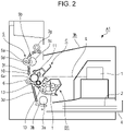
- Fig. 2 is a side cross-sectional view of the image forming apparatus.
- the image forming apparatus illustrated in Fig. 2 forms images on a recording medium (sheet) 2 by an electrophotography image forming processing using a developer t, in accordance with image information communicated from an external device such as a personal computer or the like.
- the image forming apparatus has a developing cartridge B1 and a drum cartridge C provided to an apparatus main body A1 so as to be capable of mounting and detaching by a user.
- Examples of the recording medium 2 includes recording paper, label sheets, OHP sheets, cloth, and so forth.
- the developing cartridge B1 has a developing roller 13 and so forth as a developer bearing member
- the drum cartridge C has the photosensitive drum 10 and a charging roller 11 and so forth as an image bearing member.
- the surface of the photosensitive drum 10 is uniformly charged by the charging roller 11, by application of voltage from the apparatus main body A1.
- the charged photosensitive drum 10 is then irradiated by laser light L in accordance with image information from optical unit 1, thereby forming an electrostatic latent image on the photosensitive drum 10 in accordance with image information.
- This electrostatic latent image is developed by developer t, by a later-described developing unit, thereby forming a developer image on the surface of the photosensitive drum 10.
- the recording medium 2 accommodated in a sheet feed tray 4 is separated and fed one sheet at a time, being regulated by a sheet feed roller 3a and a separating pad 3b in pressure contact therewith, synchronously with formation of the developer image.
- the recording medium 2 is then conveyed by a conveyance guide 3d to a transfer roller 6 that serves as a transfer.
- the transfer roller 6 is biased so as to come into contact with the surface of the photosensitive drum 10.
- the recording medium 2 passes a transfer nip portion 6a formed by the photosensitive drum 10 and transfer roller 6. Voltage of polarity inverse to that of the developer is applied to the transfer roller 6 at this time, whereby the developer image formed on the surface of the photosensitive drum 10 is transferred to the recording medium 2.
- the recording medium 2 on which the developer image has been transferred is conveyed to a fixing unit 5 restricted by a conveyance guide 3f.
- the fixing unit 5 includes a drive roller 5a, and a fixing roller 5c in which is built a heater 5b. Heat and pressure are applied to the recording medium 2 as it passes a nip portion 5d formed by the drive roller 5a and fixing roller 5c, thereby fixing the developer image, transferred onto the recording medium 2, on the recording medium 2. Thus, the image is formed on the recording medium 2.
- the recording medium 2 is conveyed by a discharge roller pair 3g, and discharged to a discharge part 3h.
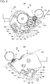
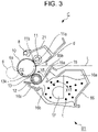
- FIG. 3 is a cross-sectional explanatory diagram of the developing cartridge B1 and the drum cartridge C.
- the developing cartridge B1 has the developing roller 13 serving as a developing unit, a developing blade 15, and so forth, in a developing container 16, as illustrated in Fig. 3 .
- the developing cartridge B1 is a developing device that has been formed into a cartridge, and is detachably mounted to the apparatus main body of the image forming apparatus.
- the drum cartridge C also has the photosensitive drum 10, charging roller 11, and so forth in a cleaning frame (photosensitive member supporting frame) 21.
- the drum cartridge C also is detachably mounted to the apparatus main body of the image forming apparatus.
- the developer t stored in a developer accommodation part 16a of the developing container 16 is fed out from an opening 16b of the developing container 16 to a developing chamber 16c, by a developer conveyance member 17 rotatably supported by the developing container 16 rotating in the direction of an arrow X17.
- the developing roller 13 having a built-in magnet roller 12 is provided in the developing container 16.
- the developing roller 13 is configured of a shaft part 13e and rubber part 13d.
- the shaft part 13e is an electroconductive slender cylindrical object of aluminum or the like, and the middle part in the longitudinal direction thereof is covered by the rubber part 13d (see Figs. 6(a) and 6(b) ).
- the developing roller 13 draws the developer t in the developing chamber 16c to the surface of the developing roller 13 by the magnetism of the magnet roller 12.
- the developing blade 15 is configured or a supporting member 15a made up of a metal plate, and an elastic member 15b made of urethane rubber, a SUS plate, or the like, with the elastic member 15b being disposed so as to be in elastic contact with the developing roller 13 at a certain contact pressure.
- the developing roller 13 rotates in a rotation direction X5, which regulates the amount of developer t adhering to the surface of the developing roller 13, and a frictional charge is imparted to the developer t.
- the developing roller 13 that has received application of voltage from the apparatus main body A1 is then rotated in the rotational direction X5 in a state of being in contact with the photosensitive drum 10, whereby developer t can be supplied to a developing region on the photosensitive drum 10.
- the developing roller 13 preferably is spaced from the photosensitive drum 10 when not developing.
- the charging roller 11 rotatably supported by the cleaning frame 21, and biased in the direction of the photosensitive drum 10, is provided in contact with the peripheral face of the photosensitive drum 10.
- the detailed configuration will be described later.
- the charging roller 11 uniformly charges the surface of the photosensitive drum 10 by application of voltage from the apparatus main body A1.
- the voltage applied to the charging roller 11 is set to a value where the potential difference between the surface of the photosensitive drum 10 and the charging roller 11 is equal to or greater than discharge charging voltage, and specifically, DC voltage of -1300 V is applied as charging bias.
- the surface of the photosensitive drum 10 is uniformly charged by contact to charging potential (dark potential) of -700 V.
- the charging roller 11 is driven and rotates in accordance with rotations of the photosensitive drum 10 in the present example (described in detail later).
- the electrostatic latent image on the surface of the photosensitive drum 10 is formed by laser light L from the optical unit 1. Thereafter, the developer t is transferred in accordance with the electrostatic latent image on the photosensitive drum 10, visualizing the electrostatic latent image, thus forming a developer image on the photosensitive drum 10.
- a so-called cleanerless system where no cleaning member to remove transfer residual toner t2 remaining on the photosensitive drum 10 without being transferred is provided, is exemplified in the present comparative example.
- the photosensitive drum 10 is rotationally driven in the direction of arrow C5, as illustrated in Fig. 3 .
- the transfer residual toner t2 remaining on the surface of the photosensitive drum 10 after the transfer process is charged to the same negative polarity as the photosensitive drum, by discharge at this upstream gap portion 11b. At this time, the surface of the photosensitive drum 10 is charged to -700 V.
- the transfer residual toner t2 that has passed through the charging nip portion 11a reaches a laser irradiation position d.
- the transfer residual toner t2 is not of an amount sufficient to shield the laser light L from the optical unit, and accordingly does not affect the process of creating the electrostatic latent image on the photosensitive drum 10.
- the transfer residual toner t2 that has passed the laser irradiation position d and also is at non-exposed portions (the surface of the photosensitive drum 10 where laser irradiation has not been performed) is recovered by electrostatic force to the developing roller 13, at a developing nip portion 13k which is where the developing roller 13 and the photosensitive drum 10 come into contact.
- transfer residual toner t2 at exposed portions (the surface of the photosensitive drum 10 where laser irradiation has been performed) is not recovered by electrostatic force but continues to exist on the photosensitive drum 10. However, some of the transfer residual toner t2 may be recovered due to physical force due to the circumferential speed difference between the developing roller 13 and the photosensitive drum 10.
- the transfer residual toner t2 that is not transferred onto paper but remains on the photosensitive drum 10 is this generally recovered to the developing container 16.
- the transfer residual toner t2 recovered to the developing container 16 is mixed with the developer t remaining in the developing container 16 and used.
- a first is that an optical destaticizing member 8 is provided between the transfer roller 6 and the charging roller 11.
- the optical destaticizing member 8 is situated on the upstream side of the charging nip portion 11a in the rotational direction of the photosensitive drum 10 (arrow C5).
- Optical destaticizing of the surface of the photosensitive drum 10 that has passed the transfer nip portion 6a is performed, in order to perform stable discharging at the upstream gap portion 11b.
- the second is that the charging roller 11 is driven rotationally so as to have a predetermined circumferential difference as to the photosensitive drum 10. While almost all toner is negatively charged due to the discharge as described above, there is some transfer residual toner t2 remaining that was not completely negatively charged, and this transfer residual toner t2 may adhere to the charging roller 11 at the charging nip portion 11a.
- Rotationally driving the charging roller 11 and photosensitive drum 10 is a predetermined circumferential speed difference therebetween enables such transfer residual toner t2 to be negatively changed by friction between the photosensitive drum 10 and charging roller 11. This is effective in suppressing adhesion of the transfer residual toner t2 to the charging roller 11.
- a charging roller gear 69 ( Fig.
- the charging roller 11 is provided on one end of the charging roller 11 in the longitudinal direction, with the charging roller gear 69 engaging a driving side flange 24 ( Fig. 16(b) , details will be described later) provided on one end of the photosensitive drum 10 in the longitudinal direction. Accordingly, the charging roller 11 also is rotationally driven in conjunction with the rotational driving of the photosensitive drum 10.
- the circumferential speed of the surface of the charging roller 11 is set to be around 105 to 120% as to the circumferential speed of the surface of the photosensitive drum 10.
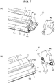
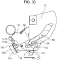
- Fig. 4 is a perspective explanatory view of the developing cartridge B1 as viewed from the driving side.
- Fig. 5 is a perspective explanatory view of the developing cartridge B1 as viewed from the non-driving side.
- Figs. 6(a) and 6(b) are perspective explanatory diagrams from the driving side ( Fig.
- FIG. 6(a) and a perspective explanatory diagram from the non-driving side ( Fig. 6(b) ), with the driving side of the developing cartridge B1 disassembled.
- Figs. 7(a) and 7(b) are perspective explanatory diagrams from the non-driving side ( Fig. 7(a) ) and a perspective explanatory diagram from the driving side ( Fig. 7(b) ), with the non-driving side of the developing cartridge B1 disassembled.
- the developing cartridge B1 has the developing roller 13, developing blade 15, and so forth, as illustrated in Figs. 6 and 7 .
- the developing blade 15 has a driving-side end portion 15a1 and non-driving-side end portion 15a2 of in the longitudinal direction of the supporting member 15a fixed to the developing container 16 by a screw 51 and a screw 52.
- a driving-side developing bearing 36 and a non-driving-side developing bearing 46 are disposed on the respective longitudinal-direction ends of the developing container 16.
- the developing roller 13 has a driving-side end portion 13a fit to a hole 36a of the driving-side developing bearing 36.
- a non-driving-side end portion 13c is fit to a supporting part 46f of the non-driving-side developing bearing 46.
- the developing roller 13 is rotatably supported by the developing container 16.
- a developing roller gear 29 is concentrically disposed with the developing roller 13 on the driving-side end portion 13a of the developing roller 13, further on the outside in the longitudinal direction from the driving-side developing bearing 36, so that the developing roller 13 and the developing roller gear 29 are integrally rotatable (see Fig. 4 ).
- the developing roller gear 29 is a helical gear.
- the driving-side developing bearing 36 rotatably supports a drive input gear 27 at the outer side in the longitudinal direction thereof.
- the drive input gear 27 and the developing roller gear 29 mesh.
- the drive input gear 27 also is a helical gear.
- the drive input gear 27 has more teeth than the developing roller gear 29 has teeth.
- a coupling member 180 is also provided concentrically with the drive input gear 27.
- a developing side cover 34 is provided at the farthest end of the developing cartridge B1 at the driving side, covering the drive input gear 27 and so forth from the outside in the longitudinal direction.
- the frame of the developing cartridge made up of the developing container 16, non-driving-side developing bearing 46, driving-side developing bearing 36, and developing side cover 34, is referred to as a developing frame.
- the coupling member 180 protrudes outwards in the longitudinal direction through a hole 34a in the developing side cover 34.
- the coupling member 180 serving as a drive input member is configured to engage a main body side drive member 100 provided to the apparatus main body A1, with rotational force being transmitted (input), which will be described in detail later.
- the configuration is such that the rotational force is transmitted to a rotational force reception part 27d1 (see Fig. 8(b) ) and rotational force reception part 27d2 (omitted from illustration) of the drive input gear 27, via rotational force transmission parts 180c1 and 180c2 of the coupling member 180. Consequently, the configuration is such that the rotational force input to the coupling member 180 is transmitted to the developing roller 13 serving as a rotating member, via the drive input gear 27 and the developing roller gear 29.
- a first movable member 120 is provided to the driving-side developing bearing 36.
- the first movable member 120 is configured including a driving-side contacting/spacing lever 70 serving as a first main part, and a driving-side developing pressure spring 71 serving as a first elastic part (a part or member that elastically deforms).
- the driving-side contacting/spacing lever 70 is a member that receives elastic force of the driving-side developing pressure spring 71.
- first main part and the first elastic part are configured as separate members in the present comparative example.
- first main part and the first elastic part may be integrally formed in the first movable member 120, and the configuration thereof is not restricted.
- a second movable member 121 is provided to the non-driving-side developing bearing 46.
- the second movable member 121 is configured including a non-driving-side contacting/spacing lever 72 serving as a second main part, and a non-driving-side developing pressure spring 73 serving as a second elastic part (a part or member that elastically deforms).
- the non-driving-side contacting/spacing lever 72 is a member that receives elastic force of the non-driving-side developing pressure spring 73.
- the second main part and the second elastic part are configured as separate members in the present comparative example.
- the second main part and the second elastic part may be integrally formed in the second movable member 121, and the configuration thereof is not restricted.
- the coupling member 180 and peripheral configurations will be described below in detail.
- the coupling member 180, the drive input gear 27, and a coupling spring 185 are provided on the driving side of the developing cartridge B1, as illustrated in Figs. 6(a) and 6(b) .
- the coupling member 180 engages the main body side drive member 100 provided to the apparatus main body A1, and rotational force is transmitted.
- the coupling member 180 is configured primarily including rotational force receiving parts 180a1 and 180a2, a supported part 180b, rotational force transmitting parts 180c1 and 180c2, and a guided part 180d, as illustrated in Fig. 8(b) .
- the rotational force receiving parts 180a1 and 180a2 of the coupling member 180 are disposed further outside in the longitudinal direction from a driving-side end portion 27a of the drive input gear 27 (see Figs. 8(a) and 8(b) ).
- a rotational force applying part 100a1 of the main body side drive member 100 comes into contact with the rotational force receiving part 180a1.
- a rotational force applying part 100a2 of the main body side drive member 100 comes into contact with the rotational force receiving part 180a2.
- the rotational force is transmitted from the main body side drive member 100 to the coupling member 180.
- the supported part 180b of the coupling member 180 is generally spherical in shape, as illustrated in Figs. 8(b) and 8(e) , with the supported part 180b being supported by a supporting part 27b on an inner circumferential face of the drive input gear 27.
- the rotational force transmitting parts 180c1 and 180c2 are provided on the supported part 180b of the coupling member 180.
- the rotational force transmitting part 180c1 comes into contact with the rotational force reception part 27d1 of the drive input gear 27.
- the rotational force transmitting part 180c2 comes into contact with the rotational force reception part 27d2 of the drive input gear 27. Accordingly, the drive input gear 27 is driven by the coupling member 180 that has been driven by the main body side drive member 100, so the drive input gear 27 rotates in the forward rotation direction X6 around the rotational axis L3.
- the rotational axis L4 of the main body side drive member 100 and the rotational axis L3 of the drive input gear 27 are set so as to be concentric, as illustrated in Fig. 8(c) .
- the rotational axis L4 of the main body side drive member 100 and the rotational axis L3 of the drive input gear 27 are slightly shifted in parallel from being concentric, due to variance in dimensions of parts and so forth, as illustrated in Fig. 8(d) .
- the rotational axis L2 of the coupling member 180 rotates in a state of being inclined with respect to the rotational axis L3 of the drive input gear 27, and rotational force is transmitted from the main body side drive member 100 to the coupling member 180.
- rotational axis L3 of the drive input gear 27 is shifted from being concentric as to the rotational axis L4 of the main body side drive member 100, with an angle therebetween.
- rotational force is transmitted from the main body side drive member 100 to the coupling member 180 in a state where the rotational axis L2 of the coupling member 180 is inclined with respect to the rotational axis L4 of the main body side drive member 100.
- a gear portion 27c that is a helical gear or a spur gear is integrally formed with the drive input gear 27, concentrically with the rotational axis L3 of the drive input gear 27 (a helical gear is used in the present comparative example).
- the gear portion 27c meshes with a gear portion 29a of the developing roller gear 29.
- the developing roller gear 29 rotates integrally with the developing roller 13, and accordingly rotational force of the drive input gear 27 is transmitted to the developing roller 13 via the developing roller gear 29.
- the developing roller 13 rotates in rotational direction X5 around a rotational axis L9.
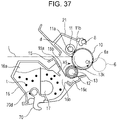
- a memory board 47 serving as a contact part, and an electrode portion 47a serving as an exposed face, that are provided at the non-driving side end portion of the developing cartridge B1, will be described with reference to Figs. 33(a) and 33(b) .
- the memory board 47 is provided on the outer circumference side of the non-driving-side developing bearing 46, and to the side of the supporting part 46f that rotatably supports the developing roller 13 as viewed from the non-driving-side contacting/spacing lever 72.
- the memory board 47 stores the manufacturing lot and property information of the developing cartridge B1, which is used for image formation by the apparatus main body A1.
- the electrode portion 47a made of metal such as iron, copper, or the like, is provided to the memory board 47, and when performing image formation, electrically connects to the apparatus main body A1 via the memory board 47 to perform communication.
- Both ends of the memory board 47 are inserted into a first substrate supporting part 46m and a second substrate supporting part 46n provided on the non-driving-side developing bearing 46.
- the memory board 47 and the first substrate supporting part 46m and second substrate supporting part 46n are fixed by press fitting, adhesion, or the like.
- the memory board 47 is provided with multiple electrode portions 47a.
- the direction in which these multiple electrode portions 47a are arrayed, and the direction of insertion of the memory board 47 to the first substrate supporting part 46m and second substrate supporting part 46n is the same direction.
- FIGs. 9(a) through 9(d) are a perspective explanatory diagram and side views illustrating the way in which the coupling lever 55 and a coupling lever spring 56 are assembled to the developing side cover 34.
- the coupling lever 55 and coupling lever spring 56 are assembled on the inner side of the developing side cover 34 in the longitudinal direction. Specifically, a cylindrically-shaped lever positioning boss 34m of the developing side cover 34 and a hole 55c of the coupling lever 55 are fit together, and the coupling lever 55 is rotatably supported by the developing side cover 34 centered on a rotational axis L11.
- the coupling lever spring 56 is a torsion spring, with one end engaging the coupling lever 55 and the other end engaging the developing side cover 34.
- an operating arm 56a of the coupling lever spring 56 engages a spring hook part 55b of the coupling lever 55
- a fixed arm 56c of the coupling lever spring 56 engages a spring hook part 34s of the developing side cover 34 (see Fig. 9(c) ).
- the coupling spring 185 is assembled on the outer side of the developing side cover 34 in the longitudinal direction, which will be described in detail later.
- a method for assembling the coupling lever 55 and the coupling lever spring 56 to the developing side cover 34 will be described in order.
- a cylindrical part 56d of the coupling lever spring 56 is attached to a cylindrical boss 55a of the coupling lever 55 ( Fig. 9(a) ).
- the operating arm 56a of the coupling lever spring 56 engages the spring hook part 55b of the coupling lever 55 at this time.
- the fixed arm 56c of the coupling lever spring 56 is deformed in the direction of arrow X11 centered on the rotational axis L11.
- the hole 55c of the coupling lever 55 is inserted onto the lever positioning boss 34m of the developing side cover 34 ( Figs. 9(a) and 9(b) ).
- a locking part 55d of the coupling lever 55 is positioned so as to not interfere with a locked part 34n of the developing side cover 34.
- the locking part 55d of the coupling lever 55 and the locked part 34n of the developing side cover 34 are positioned so as to not overlap when viewed from the longitudinal direction, as illustrated in Fig. 9(b) .
- the fixed arm 56c of the coupling lever spring 56 is deformed in the direction of arrow X11, as described earlier.
- the fixed arm 56c engages the spring hook part 34s of the developing side cover 34.
- the configuration is such that the spring hook part 34s of the developing side cover 34 receives the biasing force of the deformed fixed arm 56c of the coupling lever spring 56. Consequently, the fixed arm 56c of the coupling lever spring 56 receives reactive force from the spring hook part 34s of the developing side cover 34 in the direction of arrow X11.
- the coupling lever 55 receives biasing force from the coupling lever spring 56 at the spring hook part 55b.
- the coupling lever 55 rotates centered on the rotational axis L11 in the direction of arrow X11, and rotation is restricted at a position where a rotation restricting part 55y abuts a restricting face 34y of the developing side cover 34 (see Figs. 9a through 9(c) ).
- the assembling of the coupling lever 55 and coupling lever spring 56 to the developing side cover 34 ends.
- the locking part 55d of the coupling lever 55 is in a state of overlapping the locked part 34n of the developing side cover 34 as viewed in the longitudinal direction. That is to say, the coupling lever 55 is configured such that movement in the longitudinal direction is restricted, and only rotation centered on the rotational axis X11 is enabled.
- Fig. 9(d) is a cross-sectional view of the locking part 55d of the coupling lever 55.
- the developing side cover 34 where the coupling lever 55 and coupling lever spring 56 are integral, is fixed on the outer side of the driving-side developing bearing 36 in the longitudinal direction, as illustrated in Fig. 10 . Specifically, a positioning part 34r1 of the developing side cover 34 and a positioned part 36e1 of the driving-side developing bearing 36 are engaged. The configuration is such that the developing side cover 34 is positioned as to the driving-side developing bearing 36 by the positioning part 34r2 and the positioned part 36e2 being engaged.
- the method of fixing to the driving-side developing bearing 36 of the developing side cover 34 may be by screwing, adhesive agent, or the like, and the configuration thereof is not restricted.
- the coupling member 180 has a configuration that is exposed on the other side of the developing cartridge B1 in the longitudinal direction (see Figs. 4 , 6(a), and 6(b) ).
- the guided part 180d of the coupling member 180 (see Figs. 8(a) through 8(e) ) has a configuration that abuts a guide part 55e of the coupling lever 55.
- the coupling lever 55 is configured such that biasing force acts in the direction of the arrow X11, centered on the rotational axis L11. Accordingly, the coupling member 180 receives biasing force F2 from the coupling lever 55 (see Fig. 10(b) ).
- the coupling spring 185 is disposed at the developing side cover 34.
- the coupling spring 185 is a torsion coil spring, with one end abutting the developing side cover 34 and the other end abutting the coupling member 180.
- a positioning part 185a of the coupling spring 185 is supported by a spring supporting part 34h of the developing side cover 34.
- a fixed arm 185b of the coupling spring 185 is fixed to a spring engaging part 34j of the developing side cover 34.
- the configuration is such that an operating arm 185c of the coupling spring 185 abuts a guided member 180d of the coupling member 180.
- the operating arm 185c of the coupling spring 185 is configured such that biasing force acts in a direction of arrow L12 centered on rotational axis X12 that is centered on the positioning part 185a. Accordingly, the coupling member 180 receives biasing force F1b from the coupling spring 185 (see Fig. 10(c) ).
- the coupling member 180 that has received the biasing force F2 from the coupling lever 55 and the biasing force F1b from the coupling spring 185 is held at an attitude (rotational axis L2) included as to the rotational axis L3 of the drive input gear 27 ( Fig. 10(b) ).
- attitude rotational axis L2 included as to the rotational axis L3 of the drive input gear 27 ( Fig. 10(b) ).
- the configuration of holding the inclined attitude of the coupling member 180 at this time and the operation of forces will be described later in "Relationship of Forces Acting on Coupling Member 180 when in Second Inclined Attitude D2" described later.
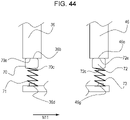
- Fig. 15(a) is an enlarged diagram illustrating the relationship between the coupling member 180, drive input gear 27, and driving-side developing bearing 36, in a longitudinal-section view.
- Fig. 15(b) is a perspective view of the driving-side developing bearing 36.
- Fig. 15(c) is a perspective view of the drive input gear 27.
- the supported part 180b of the coupling member 180 is disposed on an interior 27t of the drive input gear 27, and further is wedged between a restricting part 27s of the drive input gear 27 and a coupling restricting part 36s of the driving-side developing bearing 36.
- a diameter r180 of the supported part 180b of the coupling member 180 is in a relationship of being equal to or smaller than a width r27 of the restricting part 27s of the drive input gear 27 in the direction of X180 and a width r36 of the coupling restricting part 36s of the driving-side developing bearing 36 in the direction of X180.
- the coupling member 180 is configured so as to be capable of tilting in an R180 direction centered on center 180s of the supported part 180b, even though movement in the longitudinal direction Y180 and cross-sectional direction X180 is restricted.
- the coupling member 180 has a configuration that receives driving force from the main body side drive member 100 of the apparatus main body A1 and is capable of rotating on the rotational axis L2, as described above.
- the rotational axis L2 of the coupling member 180 is set to be concentric with the rotational axis L3 of the drive input gear 27 when transmitting driving force. Further description has been made that there are cases where the rotational axis L2 of the coupling member 180 and the rotational axis L3 of the drive input gear 27 are not concentric but slightly shifted, due to variance in dimensions of parts and so forth.
- the present configuration enables the rotational axis L2 of the coupling member 180 to incline in the following directions. These can be generally classified into the following three attitudes.
- Fig. 13 is diagrams illustrating the relationship between the driving-side developing bearing 36 and the coupling member 180.
- Fig. 13(a) is a perspective view illustrating the positions of the driving-side developing bearing 36 and the coupling member 180.
- Fig. 13(b) is a diagram of the driving-side developing bearing 36 as viewed from the front at the driving side.
- Fig. 13(c) is a diagram where the coupling member 180 has been added to a view taken along a cross-section XIIIC in Fig. 13(b), and
- Fig. 13(d) is a diagram where the coupling member 180 has been added to a view taken along a cross-section XIIID in Fig. 13(b) .
- a phase-restricting boss 180e is provided on the coupling member 180, concentrically with the rotational axis L2 and on the inner side in the longitudinal direction, as illustrated in Fig. 13(a) .
- a recessed phase-restricting part 36kb is provided to the driving-side developing bearing 36.
- the phase-restricting part 36kb particularly is provided with a first inclination restricting part 36kb1 that is recessed in the direction of arrow K1a, and a second inclination restricting part 36kb2 that is recessed in the direction of arrow K2a, from the center of the rotational axis L3 of the drive input gear 27.
- the phase-restricting boss 180e of the coupling member 180 is situated within the phase-restricting part 36kb of the driving-side developing bearing 36. That is to say, the phase-restricting boss 180e of the coupling member 180 is positionally restricted by the phase-restricting part 36kb of the driving-side developing bearing 36. In other words, the phase-restricting boss 180e of the coupling member 180 is capable of moving within the phase-restricting part 36kb of the driving-side developing bearing 36, and particularly can move to the first inclination restricting part 36kb1 and second inclination restricting part 36kb2.
- the attitude of the coupling member 180 will be described in detail below with reference to Figs. 21(a) through 22(d) , regarding the reference attitude DO of the coupling member 180.
- Fig. 22 is diagrams illustrating the position of the coupling lever 55 and the coupling member 180 at a point where the mounting of the developing cartridge B1 to the apparatus main body A1 is complete.
- Fig. 22(a) is a side view as seen from the driving side
- Fig. 22(b) is a side view as seen from the direction of arrow XXIIB in Fig. 22(a)
- Fig. 22(c) is a side view as seen from the non-driving side with a cutaway taken along cutaway line XXIIC in Fig. 22(b) .
- the coupling member 180 engages the main body side drive member 100.
- the rotational axis L2 of the coupling member 180, the rotational axis L4 of the main body side drive member 100, and the rotational axis L3 of the drive input gear 27, are concentrically disposed.
- the rotational force receiving part 180a of the coupling member 180 and the rotational force applying part 100a (rotational force applying part 100a1 and rotational force applying part 100a2) of the main body side drive member 100 are at positions capable of engaging each other (see Fig. 8(b) as well).
- Figs. 34(a) through 34(c) are cross-sectional views illustrating the attitude of the coupling member until the coupling member 180 becomes concentric with the main body side drive member 100.
- Fig. 34(a) is a cross-sectional diagram illustrating a state where the coupling member 180 is not in contact with the main body side drive member 100
- Fig. 34(b) is a cross-sectional view illustrating a state of the instant of contact of the coupling member 180 with the main body side drive member 100
- Fig. 34(c) is a cross-sectional view of a state where the coupling member 180 is concentric with the main body side drive member 100.
- the coupling member 180 In a state where the coupling member 180 is not in contact with the main body side drive member 100, the coupling member 180 is inclined in the direction of the main body side drive member 100, the inclination being centered on the center 180s of the supported part 180b of the coupling member 180, as illustrated in Fig. 34(a) .
- the coupling member 180 advances in the direction of arrow X60, which is the direction in which the main body side drive member 100 exists, while maintaining this attitude.
- the coupling member 180 moves in a direction where the inclination of the coupling member 180 is reduced, the inclination being centered on the center 180s of the supported part 180b of the coupling member 180.
- the rotational axis L2 of the coupling member 180, the rotational axis L4 of the main body side drive member 100, and the rotational axis L3 of the drive input gear 27, are concentrically arranged. Forces that the coupling member 180 is subjected to in this series of operations will be described in detail later, so description will be omitted here.
- the phase-restricting boss 180e of the coupling member 180 detaches from the second inclination restricting part 36kb2 of the driving-side developing bearing 36, and is not in contact with any part of a phase restricting part 36b of the driving-side developing bearing 36 (see Fig. 22(c) ).
- the guide part 55e of the coupling lever 55 is held at a state completely retracted from the guided part 180d of the coupling member 180 ( Fig. 22(a) ).
- the coupling member 180 comes into contact with two parts, which are the coupling spring 185 and the main body side drive member 100, which decides the angle of inclination ( ⁇ 2) thereof.
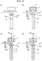
- the inclination attitude (reference attitude D0) of the coupling member 180 in a case where mounting of the developing cartridge B1 to the apparatus main body A1 is complete will be described below in detail, with reference to Fig. 14 .
- Fig. 14 is diagrams illustrating the way in which the coupling member 180 and the main body side drive member 100 engage.
- the states illustrated in Fig. 14(a) and Fig. 14(b) are a side view and cross-sectional view of a case where the rotational axis L3 of the drive input gear 27 and the rotational axis L4 of the main body side drive member 100 are concentrically arranged, and moreover the rotational axis L2 of the coupling member 180 also is concentric.
- the guided part 180d of the coupling member 180 receives biasing force from the coupling spring 185 in the direction of arrow F1 (see Fig. 22(d) ), with the conical part 180g abutting the protrusion 100g at points 180g1 and 180g2 ( Fig. 8(e) ). Consequently, the attitude of the coupling member 180 with respect to the main body side drive member 100 is restricted by the two points 180g1 and 180g2 of the conical part 180g. That is to say, the rotational axis L2 of the coupling member 180 is concentric with the rotational axis L4 of the main body side drive member 100.
- the state illustrated in Fig. 14(c) is a state where the rotational axis L3 of the drive input gear 27 and the rotational axis L4 of the main body side drive member 100 are disposed concentrically, but the rotational axis L2 of the coupling member 180 is inclined. Due to variance in dimensions of parts, the conical part 180g of the coupling member 180 abuts the protrusion 100g of the main body side drive member 100 and the point 180g1 of the conical part 180g but not the point 180g2 of the conical part 180g. The rotational axis L2 of the coupling member 180 inclines at this time, by the guided part 180d of the coupling member 180 receiving biasing force from the coupling spring 185 in the direction of arrow F1.
- Fig. 14(d) illustrates a state where the rotational axis L2 of the coupling member 180 is included, in a case where the rotational axis L3 of the drive input gear 27 and the rotational axis L4 of the main body side drive member 100 are not concentric, due to variance in the dimensions of parts (see Fig. 8(d) ).
- the attitude of the coupling member 180 is restricted by the point 180g1 of the conical part 180g of the coupling member 180 coming into contact with the protrusion 100g of the main body side drive member 100, the same as in in Fig. 14(c) .
- the attitude of the coupling member 180 in a state where mounting of the developing cartridge B1 to the apparatus main body A1 has been completed, and the coupling member 180 can receive driving force from the rotational force applying part 100a of the apparatus main body A1, is referred to as the reference attitude D0 of the coupling member 180.
- the configuration is such that the inclination angle is within a range where the rotational force applying part 100a of the main body side drive member 100 and the rotational force receiving part 180a of the coupling member 180 do not come loose from each other.
- the first inclined attitude D1 and second inclined attitude D2 of the coupling member 180 will be described in detail in order blow.
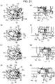
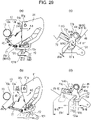
- Fig. 11(a) is a side view of the developing cartridge B1, in a state where the developing cartridge B1 is mounted within the apparatus main body A1 and in a spaced state where the photosensitive drum 10 and the developing roller 13 are spaced.
- Fig. 11(b) is a cross-sectional view of the phase-restricting boss 180e of the coupling member 180 within the phase-restricting part 36kb of the driving-side developing bearing 36, as seen from the non-driving side of the developing cartridge B1.
- Fig. 11(c) is a cross-sectional view of the guided part 180d of the coupling member 180, cut away at the position of the guided part 180d of the coupling member 180, and viewed from the driving side in the longitudinal direction.
- the coupling lever 55 receives biasing force from the coupling lever spring 56 (see Fig. 9(a) ), to rotate in the direction of arrow X11 centered on rotational axis L11.
- movement in the direction of arrow X11 is restricted by an abutting part 80y provided to the apparatus main body A1.
- the position of the coupling lever 55 is restricted against the biasing force of the coupling lever spring 56, by the abutting part 80y and a rotation restricting part 55y of the coupling lever 55 coming into contact.
- the abutting part 80y is formed integrally with a driving-side swing guide 80 (see Fig. 20(b) ).
- the guide part 55e of the coupling lever 55 is in a retracted state from the guided part 180d of the coupling member 180. Contact between the coupling lever 55 and the abutting part 80y will be described in detail in the detaching process of the developing cartridge B1, described later.
- force F1a acts on the guided part 180d of the coupling member 180, due to a guide part 185d of the coupling spring 185 coming into contact therewith. That is to say, the guided part 180d of the coupling member 180 receives force inclining in the direction of arrow F1a (see Fig. 11(c) ).
- the phase-restricting boss 180e of the coupling member 180 is configured to be restricted by a guide part 36kb1a, guide part 36kb1b, and guide part 36kb1c of the driving-side developing bearing 36 at this time, and is configured to finally move to the first inclination restricting part 36kb1.
- the configuration is such that the phase-restricting boss 180e of the coupling member 180 inclines in the direction of arrow K1a ( Fig. 11(b) ), while on the other hand, the rotational force receiving part 180a and guided part 180d of the coupling member 180 incline in the direction of arrow K1b ( Fig. 11(a) ).
- the above-described attitude of the coupling member 180 is referred to as first inclined attitude D1 of the coupling member 180.
- the orientation of the guide part 185d of the coupling spring 185 can be orthogonal in direction with respect to the direction of arrow K1b (see Fig. 11(a) ), with respect to the guided part 180d of the coupling member 180.
- This direction is a direction of the phase-restricting boss 180e of the coupling member 180 abutting the first inclination restricting part 36kb1, thereby enabling reduction of the biasing force of the coupling spring 185 to maintain the first inclined attitude D1 of the coupling member 180.
- this is not restrictive, as long as the coupling member 180 can be maintained at the first inclined attitude D1 by adjusting the biasing force of the coupling spring 185 or the like.
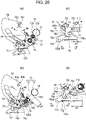
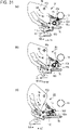
- Fig. 12(a) is a side view of the developing cartridge B1, illustrating a state of the developing cartridge B1 before mounting to the apparatus main body A1, i.e., in a solitary state (natural state) of the developing cartridge B1.
- Fig. 12(b) is a cross-sectional view of the position of the phase-restricting boss 180e of the coupling member 180 within the phase-restricting part 36kb of the driving-side developing bearing 36, as viewed from the non-driving side of the developing cartridge B1.
- Fig. 12(c) is a cross-sectional view where the guided part 180d of the coupling member 180 has been cut away, and viewed from the driving side in the longitudinal direction.
- FIG. 12(a) illustrates a state where there is no abutting part 80y provided to the apparatus main body A1 in Fig. 11(a) .
- the coupling lever 55 receives biasing force from the coupling lever spring 56 in the direction of arrow X11 centered on rotational axis L11, and rotates to a position where the guide part 55e thereof comes into contact with the guided part 180d of the coupling member 180. That is to say, the guide part 55e of the coupling lever 55 and the guide part 185d of the coupling spring 185 both come into contact with the guided part 180d of the coupling member 180.
- the guided part 180d of the coupling member 180 receives force inclining in the direction of arrow F3, as described above.
- the phase-restricting boss 180e of the coupling member 180 is configured to be restricted by a guide part 36kb2a, guide part 36kb2b, and guide part 36kb2c of the driving-side developing bearing 36, and is configured to finally move to the second inclination restricting part 36kb2. That is to say, the configuration is such that the phase-restricting boss 180e of the coupling member 180 inclines in the direction of arrow K2a ( Fig.
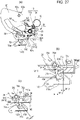
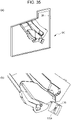
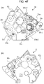
- Fig. 16(a) is a perspective explanatory diagram of the drum cartridge C as viewed from the non-driving side thereof.
- Fig. 16(b) is a perspective explanatory diagram where the cleaning frame 21, drum bearing 30, drum shaft 54, and so forth, have been omitted from illustration to describe the periphery of the photosensitive drum 10 and charging roller 11.
- the drum cartridge C has the photosensitive drum 10, charging roller 11, and so forth, as illustrated in Fig. 16 .
- the charging roller 11 is rotatably supported by a charging roller bearing 67a and charging roller bearing 67b, and is biased as to the photosensitive drum 10 by a charging roller biasing member 68a and charging roller biasing member 68b.
- the driving side flange 24 is integrally fixed to a driving-side end portion 10a of the photosensitive drum 10, and a non-driving side flange 28 is integrally fixed to a non-driving-side end portion 10b of the photosensitive drum 10.
- the driving side flange 24 and non-driving side flange 28 are concentrically fixed to the photosensitive drum 10 by swaging, adhesion, or the like. Means such as screwing, adhesion, press fitting, or the like are used to fix the drum bearing 30 to the driving-side end portion and the drum shaft 54 to the non-driving-side end portion, at both ends of the cleaning frame 21 in the longitudinal direction.
- the driving side flange 24, integrally fixed to the photosensitive drum 10, is rotatably supported by the drum bearing 30, and the non-driving side flange 28 is rotatably supported by the drum shaft 54.
- the charging roller gear 69 is provided on one end of the charging roller 11 in the longitudinal direction, with the charging roller gear 69 meshing with a gear portion 24g of the driving side flange 24.
- the configuration is such that rotational force from the apparatus main body A1 side is transmitted to a driving-side end portion 24a of the driving side flange 24 (omitted from illustration).
- the charging roller 11 also is rotationally driven.
- the circumferential speed of the surface of the charging roller 11 is set to be around 105 to 120% as to the circumferential speed of the surface of the photosensitive drum 10, as described earlier.
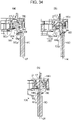
- Fig. 17 is a perspective explanatory diagram viewing the apparatus main body A1 from the non-driving side
- Fig. 18 is a perspective explanatory diagram viewing the apparatus main body A1 from the driving side
- Figs. 19(a) through 19(d) are explanatory diagrams of the process of mounting the developing cartridge B1 to the apparatus main body A1, as viewed from the driving side.
- a guided part 46d having a positioning part 46b and a rotation stopper 46c is provided to the non-driving-side developing bearing 46 at the developing cartridge B1, as illustrated in Fig. 17 .
- a guided part 34d having a positioning part 34b and a rotation stopper 34c is provided to the developing side cover 34, as illustrated in Fig. 18 .
- a driving-side guide member 92 and further the driving-side swing guide 80 that moves integrally with the developing cartridge B1 within the apparatus main body A1, are provided to a driving-side side plate 90 configuring the casing of the apparatus main body A1 at the driving side at the apparatus main body A1, as illustrated in Fig. 17 . Details of the driving-side swing guide 80 will be described later.
- the driving-side guide member 92 is provided with a first guide part 92a, a second guide part 92b, and a third guide part 92c.
- a groove for a mounting/detaching path X1a following the mounting/detaching path of the developing cartridge B1 is provided to the first guide part 92a of the driving-side guide member 92, and a groove for a mounting/detaching path X1b following the mounting/detaching path of the developing cartridge B1 is provided to the second guide part 92b.
- a groove for mounting/detaching path X3 following the mounting/detaching path of the drum cartridge C is provided to the third guide part 92c of the driving-side guide member 92.
- a first guide part 80a and a second guide part 80b are provided to the driving-side swing guide 80.
- the first guide part 80a of the driving-side swing guide 80 has formed therein a groove shape following a mounting/detaching path X2a of the developing cartridge B1 as an extension of the first guide part 92a of the driving-side guide member 92.
- the second guide part 80b of the driving-side swing guide 80 has formed therein a groove shape following a mounting/detaching path X2b of the developing cartridge B1 as an extension of the second guide part 92b of the driving-side guide member 92.
- a non-driving-side guide member 93, and a non-driving-side swing guide 81 that moves in the same way as the driving-side swing guide 80, are provided to a non-driving-side side plate 91 configuring the casing of the apparatus main body A1 at the non-driving side at the apparatus main body A1, as illustrated in Fig. 18 .
- a first guide part 93a and a second guide part 93b are provided to the non-driving-side guide member 93.
- a groove shape of a mounting/detaching path XH1a following the mounting/detaching path of the developing cartridge B1 is formed at the first guide part 93a of the non-driving-side guide member 93.
- a groove shape of a mounting/detaching path XH3 following the mounting/detaching path of the drum cartridge C is formed at the second guide part 93b of the non-driving-side guide member 93.
- a guide part 81a is provided to the non-driving-side swing guide 81.
- a groove shape of a mounting/detaching path XH2a following the mounting/detaching path of the developing cartridge B1 is provided to the guide part of the guide part 81a of the non-driving-side swing guide 81 as an extension of the first guide part 93a of the non-driving-side guide member 93.
- the non-driving-side side plate 91 is provided with an electric supply unit 120, at a position that faces the electrode portions 47a of the memory board 47 of the developing cartridge B1 when forming images.
- the electric supply unit 120 has an electric supply contact 120A, formed of wire spring or leaf spring or the like and having spring properties, protruding from the electric supply unit 120, the electric supply contact 120A being connected to an electric board that is omitted from illustration.
- a method of mounting the developing cartridge B 1 to the apparatus main body A1 will be described below.
- the guided part 46d of the non-driving-side developing bearing 46 of the developing cartridge B1 ( Fig. 17 ) and the first guide part 93a of the non-driving-side guide member 93 of the apparatus main body A1 ( Fig. 18 ) are engaged. Further, the guided part 34d of the developing side cover 34 of the developing cartridge B1 ( Fig. 18 ) and the first guide part 92a of the driving-side guide member 92 of the apparatus main body A1 ( Fig. 17 ) are engaged.
- the developing cartridge B1 is inserted into the apparatus main body A1 following the mounting/detaching path X1a and mounting/detaching path XH1a formed by the first guide part 92a of the driving-side guide member 92 and the first guide part 93a of the non-driving-side guide member 93.
- the coupling member 180 When mounting the developing cartridge B1 to the apparatus main body A1, the coupling member 180 is in the state of the above-described second inclined attitude D2, as described earlier.
- the coupling member 180 is inserted into the second guide part 92b of the driving-side guide member 92 while maintaining the second inclined attitude D2.
- the developing cartridge B1 that is inserted into the apparatus main body A1 following the mounting/detaching paths X1a and XH1a is next inserted into the apparatus main body A1 following the mounting/detaching paths X2a and XH2a.
- the mounting/detaching paths X2a and XH2a are formed by the first guide part 80a of the driving-side swing guide 80 and the guide part 81a of the non-driving-side swing guide 81.
- the guided part 34d provided to the developing side cover 34 is guided by the first guide part 92a of the driving-side guide member 92 of the apparatus main body A1.
- the configuration is such that thereafter, as the mounting process proceeds, the guided part 34d is handed over to the first guide part 80a of the driving-side swing guide 80 of the apparatus main body A1.
- the guided part 46d provided to the non-driving-side developing bearing 46 is guided by the first guide part 93a of the non-driving-side guide member 93 of the apparatus main body A1.
- the configuration is such that thereafter, as the mounting process proceeds, the guided part 46d is handed over to the guide part 81a of the non-driving-side swing guide 81 of the apparatus main body A1.
- the coupling member 180 provided to the driving side end of the developing cartridge B1 is handed over from the second guide part 92b of the driving-side guide member 92 of the apparatus main body A1 to the second guide part 80b of the driving-side swing guide 80, while maintaining the second inclined attitude D2. Note that there is a gap between the coupling member 180 and the second guide part 80b of the driving-side swing guide 80, in the same way as that described above.
- FIGs. 19(a) through 19(d) illustrates the state of the developing cartridge B1 and the driving-side swing guide 80 during the process of the developing cartridge B1 being mounted to the apparatus main body A1.
- Fig. 19(a) illustrates a state where the guided part 34d provided to the developing side cover 34 of the developing cartridge B1 is guided by the first guide part 80a of the driving-side swing guide 80, and the developing cartridge B1 is on the mounting/detaching path X2a.
- Fig. 19(b) illustrates a state where mounting of the developing cartridge B1 has further progressed from the state in Fig. 19(a) .
- the positioning part 34b of the guided part 34d of the developing side cover 34 abuts the positioning part 82a of the driving-side pressing member 82 provided on the driving-side swing guide 80 at point P1.
- Fig. 20 is perspective explanatory diagrams illustrating the peripheral forms of the driving-side swing guide 80 and driving-side pressing member 82.
- Fig. 20(a) is a perspective view as seen from the driving side in the longitudinal direction
- Fig. 20(b) is a perspective view as seen from the non-driving side in the longitudinal direction.
- Fig. 20(c) is a disassembled perspective view of the driving-side swing guide 80, driving-side pressing member 82, and driving-side pressing spring 83.
- Fig. 20(d) and Fig. 20(e) are enlarged detailed diagrams of around the driving-side pressing member 82.
- the driving-side pressing member 82 has, in addition to the positioning part 82a, a hole 82b, a seating face 82c, and a restricting part 82d, as illustrated in Fig. 20(a) and Fig. 20(b) .
- the hole 82b engages with a boss 80c of the driving-side swing guide 80, and is rotatably supported centered on the boss 80c, as illustrated in Fig. 20(c) .
- one end portion 83c of the driving-side pressing spring 83 is in contact with the seating face 82c.
- an other end portion 83d of the driving-side pressing spring 83 is in contact with the seating face 80d of the driving-side swing guide 80, as illustrated in Fig. 20(d) .
- the driving-side pressing member 82 is configured to receive biasing force F82 in a direction of rotating in the direction of arrow Ra1 centered on the boss 80c of the driving-side swing guide 80.
- rotation of the driving-side pressing member 82 in the direction of arrow Ra1 is restricted by the restricting part 82d thereof abutting a rotation restricting part 80e provided to the driving-side swing guide 80, thereby positioning the driving-side pressing member 82.
- the driving-side pressing member 82 rotatably supported by the driving-side swing guide 80 is capable of rotating in the direction of arrow Ra2 against the biasing force F82 of the driving-side pressing spring 83, as illustrated in Fig. 20(e) .
- an upper end 82e of the driving-side pressing member 82 is capable of rotating in the direction of arrow Ra2 as far as a position where it does not protrude from a guide face 80w of the driving-side swing guide 80.
- Fig. 19(c) is a state where mounting of the developing cartridge B1 has further progressed from the state in Fig. 19(b) .
- a state is illustrated where the guided part 34d, in which the positioning part 34b and rotation stopper 34c of the developing side cover 34 are integrally formed, abuts a near-side slanted face 82w of the driving-side pressing member 82, thereby pressing the driving-side pressing member 82 downwards in the direction of arrow Ra2.
- the guided part 34d of the developing side cover 34 abuts the near-side slanted face 82w of the driving-side pressing member 82 and presses the driving-side pressing member 82.
- Fig. 19(c) is a state where the positioning part 34b of the developing side cover 34 and the upper end 82e of the driving-side pressing member 82 are in contact. At this time, the restricting part 82d of the driving-side pressing member 82 is separated from the rotation restricting part 80e of the driving-side swing guide 80.
- Fig. 19(d) is a state where mounting of the developing cartridge B1 has further progressed from the state in Fig. 19(c) , illustrating a state in which the positioning part 34d of the developing side cover 34 and a positioning part 80f of the driving-side swing guide 80 are in contact.
- the driving-side pressing member 82 has a configuration that receives biasing force F82 in the direction of rotating in the direction of arrow Ra1 centered on the boss 80c of the driving-side swing guide 80, as described above. Accordingly, a far-side slanted face 82s of the driving-side pressing member 82 biases the positioning part 34b of the developing side cover 34 by a biasing force F4. Consequently, the positioning part 34b comes into contact with the positioning part 80f of the driving-side swing guide 80 at point P3 with no gap therebetween.
- the driving side of the developing cartridge B1 is positioned and fixed at the driving-side swing guide 80.
- the configuration of the non-driving side is the same as the driving side, with the non-driving-side swing guide 81, a non-driving-side pressing member 84, and a non-driving-side pressing spring 85 being provided corresponding to the driving-side swing guide 80, driving-side pressing member 82, and driving-side pressing spring 83, as illustrated in Fig. 36 . Accordingly, positioning of the positioning part 46b of the non-driving-side developing bearing 46 and the non-driving-side swing guide 81 also is the same as at the driving side (description will be omitted). According to these, the developing cartridge B1 is positioned and fixed at the driving-side swing guide 80 and non-driving-side swing guide 81.
- Fig. 21(a) illustrates a state of mounting the developing cartridge B1 to the apparatus main body A1, and being on the mounting/detaching path X2a formed at the driving-side swing guide 80 and non-driving-side swing guide 81.
- Fig. 21(e) is a diagram of the state in Fig. 21(a) as viewed from the direction of arrow XXIE in Fig. 21(a) .
- the configuration is such that with regard to the second inclined attitude D2 of the coupling member 180, the rotational force receiving part 180a of the coupling member 180 faces in the direction of the main body side drive member 100 of the apparatus main body A1 while the developing cartridge B1 is on the mounting/detaching path X2a. More specifically, the coupling member 180 inclines in the direction of the main body side drive member 100 centered on the center 180s of the supported part 180b thereof, near where the coupling member 180 and main body side drive member 100 come into contact, which will be described later.
- the second inclination restricting part 36kb2 of the driving-side developing bearing 36 is formed so as to incline the coupling member 180 in this manner (see Figs. 12(b) , 13(a) through 13(d) , and Fig. 15(a) ).
- Fig. 21(b) illustrates a state where the developing cartridge B1 has been further inserted to the mounting/detaching path X2a from the state illustrated in Fig. 21(a).
- Fig. 21(f) is a diagram viewed from the direction of arrow XXIF in Fig. 21(b) .
- the state is such that the circular part 180f of the coupling member 180 and the main body side drive member 100 are in contact.
- the coupling member 180 is inclined in the direction of the main body side drive member 100 from the state illustrated in Fig. 21(a) to the state illustrated in Fig. 21(b) , so the coupling member 180 and the main body side drive member 100 can be easily engaged.
- the coupling member 180 maintains the second inclined attitude D2 by the guided part 180d thereof receiving total force F3 from the coupling lever spring 56 and the coupling spring 185, as described above (see Figs. 12(a) through 12(c) ).
- the angle formed between the rotational axis L3 of the drive input gear 27 and the rotational axis L2 of the coupling member 180 (inclination angle) when the coupling member 180 is at the second inclined attitude D2 is ⁇ 2a (see Fig. 21(b) ).
- Fig. 21(c) illustrates a state where the developing cartridge B1 has been further inserted to the mounting/detaching path X2a from the state illustrated in Fig. 21(b).
- Fig. 21(g) is a diagram viewed from the direction of arrow XXIG in Fig. 21(c) .
- Figs. 23(a) and 23(b) are cross-sectional diagrams illustrating the relationship of force at the periphery of the coupling member 180 when the circular part 180f of the coupling member 180 comes into contact with the main body side drive member 100.
- the rotation restricting part 55y of the coupling lever 55 and the abutting part 80y disposed on the driving-side swing guide 80 are in a state of contact.
- the inclination angle of the coupling member 180 becomes ⁇ 2b ( ⁇ ⁇ 2a) from the state illustrated in Fig. 21(b) to the state illustrated in Fig. 21(c) , by the circular part 180f thereof coming into contact with the main body side drive member 100.
- the coupling member 180 receives force F100 at the contact part from the main body side drive member 100.
- the inclination angle of the coupling member 180 becomes smaller, and nears a direction of being relatively parallel to the rotational axis L3 of the drive input gear 27. That is to say, the inclination angle changes centered on the center 180s of the supported part 180b, and becomes ⁇ 2b ⁇ ⁇ 2a (see Figs. 15(a) , 21(b) , 21(c) , and 23(a) ).
- the coupling member 180 comes into contact with four parts, which are the coupling lever 55, the coupling spring 185, the main body side drive member 100, and the phase-restricting part 36kb of the driving-side developing bearing 36, which decides the inclination angle thereof ( ⁇ 2b).
- Fig. 21(d) illustrates a state where the developing cartridge B1 has been further inserted to the mounting/detaching path X2a from the state illustrated in Fig. 21(c).
- Fig. 21(h) is a diagram viewed from the direction of arrow XXIH in Fig. 21(d) .
- the rotation restricting part 55y of the coupling lever 55 is in contact with the abutting part 80y of the driving-side swing guide 80. Accordingly, the coupling lever 55 rotates in the direction of arrow X11b centered on the rotational axis L11 relatively within the developing cartridge B1, in conjunction with the insertion of the developing cartridge B1 in the direction of the mounting/detaching path X2a.
- the guide part 55e of the coupling lever 55 also rotates in the direction of arrow X11b centered on the rotational axis L11.
- the coupling member 180 the inclination angle ⁇ 2c of the coupling member 180 decreases ( ⁇ 2c ⁇ ⁇ 2b) along the guide part 55e of the coupling lever 55 as biasing force is received from the coupling spring 185.
- the coupling member 180 comes into contact with three parts, which are the coupling spring 185, the main body side drive member 100, and the phase-restricting part 36kb of the driving-side developing bearing 36, which decides the inclination angle ( ⁇ 2c) thereof.
- Figs. 22(a) through 22(d) illustrate a state where the developing cartridge B1 has been further inserted in the direction of the mounting/detaching path X2a from the state illustrated in Fig. 21(d) , and also illustrates a state where mounting of the developing cartridge B1 to the apparatus main body A1 has been completed.
- the phase-restricting boss 180e of the coupling member 180 is separated from the second inclination restricting part 36kb2 of the driving-side developing bearing 36 at this time, and is not in contact with any part of the phase restricting part 36b of the driving-side developing bearing 36 (see Fig. 22(c) ).
- the guide part 55e of the coupling lever 55 is held in a state completely retracted from the guided part 180d of the coupling member 180. That is to say, the coupling member 180 is in contact with two parts, which are the coupling spring 185 and the main body side drive member 100, which decides the inclination angle ( ⁇ 2) thereof (see the above-described reference attitude D0 of the coupling member 180 for details).
- the operations of removing the developing cartridge B1 from the apparatus main body A1 are the reverse operations from the above-described mounting.
- the user rotates the main body cover 94 of the apparatus main body A1 in the opening direction D1 (see Fig. 17 and Fig. 18 ) in the same way as when mounting, and exposes the inside of the apparatus main body A1.
- the developing cartridge B1 is held in a contact attitude where the developing roller 13 and photosensitive drum 10 are in contact, by the driving-side swing guide 80, non-driving-side swing guide 81, and also a configuration omitted from illustration.
- the developing cartridge B1 is then moved in the removing direction following the mounting/detaching path XH2 provided to the driving-side swing guide 80 and non-driving-side swing guide 81.
- the abutting part 80y of the driving-side swing guide 80 that had been in contact with the rotation restricting part 55y of the coupling lever 55 moves (from state illustrated in Fig. 21(d) to state illustrated in Fig. 21(c) ).
- the coupling lever 55 rotates in the direction of arrow X11 centered on the rotational axis L11.
- Further moving the developing cartridge B1 causes the coupling lever 55 to rotate in the direction of arrow X11, and the guide part 55e of the coupling lever 55 comes into contact with the guided part 180d of the coupling member 180 (state illustrated in Fig. 21(c) ).
- the developing cartridge B1 is removed to the outside of the apparatus main body A1, by being moved in the removing direction following the mounting/detaching path XH1 provided to the driving-side guide member 92 and non-driving-side guide member 93.
- the developing cartridge B1 that applies biasing force to the coupling member 180 is provided with the coupling lever 55 and coupling lever spring 56, which enables the coupling member 180 to be inclined at the second inclined attitude D2.
- the direction of inclination in which the coupling member 180 is inclined by the coupling lever 55 is the direction of the mounting/detaching path X2a of the developing cartridge B1, and further, the configuration is such that the rotating operation of the coupling lever 55 occurs in conjunction with mounting/detaching operations of the developing cartridge B1 by the user.
- Fig. 1(a) is an explanatory diagram of the driving-side contacting/spacing lever 70 and peripheral form, and is a cross-sectional view of the developing cartridge B1 as seen from the driving side.
- the driving-side contacting/spacing lever 70 includes a first contact face 70a, a second contact face 70b, a third contact face 70c, a supported part 70d, a driving-side restricting contact part 70e, and a first protrusion (one end side protrusion) 70f.
- the supported part 70d of the driving-side contacting/spacing lever 70 is rotatably supported by the driving-side developing bearing 36, by a supporting part 36c of the driving-side developing bearing 36.
- a boss of the supporting part 36c of the driving-side developing bearing 36 fits to a hole in the supported part 70d of the driving-side contacting/spacing lever 70, whereby the driving-side contacting/spacing lever 70 is supported to be capable of rotation (in the directions of arrows N9 and N10) centered on the boss of the supporting part 36c. That is to say, the supporting part 36c serves as the rotational center of the driving-side contacting/spacing lever 70.
- the supporting part 36c of the driving-side developing bearing 36 is parallel to the rotational axis L0 of the developing roller 13. That is to say, the driving-side contacting/spacing lever 70 can rotate on a plane orthogonal to the rotational axis L0 of the developing roller 13.
- the driving-side restricting contact part 70e is in contact with the restricting part 36b provided to the driving-side developing bearing 36.
- Fig. 37 is a diagram where the driving-side contacting/spacing lever 70 has been projected on a cross-sectional view of the developing cartridge B1.
- the supported part 70d (the center of rotation of the driving-side contacting/spacing lever 70) is at a position overlapping the developer accommodation part 16a (i.e., within the developer accommodation part 16a) in Fig. 37 . That is to say, when the developing cartridge B1 is viewed following the direction of arrow N11 (see Fig. 4 ) that is a direction parallel to the rotational axis L0 of the developing roller 13, the supported part 70d of the driving-side contacting/spacing lever 70 is at a position overlapping the developer accommodation part 16a of the developing container 16.
- the non-driving-side contacting/spacing lever 72 has the same configuration, although omitted from illustration.
- the amount of protrusion of the driving-side contacting/spacing lever 70 and non-driving-side contacting/spacing lever 72 from the developer accommodation part 16a can be reduced, and the size of the developing cartridge B1 as viewed from the rotational axis direction of the developing roller 13 can be made compact.
- Fig. 1(b) is a side view of the developing cartridge B1 from the non-driving side. Note however, that some of the parts have been omitted from illustration, for description of the configuration of the non-driving-side contacting/spacing lever 72.
- the non-driving-side contacting/spacing lever 72 has a non-driving-side first contact face 72a, a non-driving-side second contact face 72b, a non-driving-side third contact face 72c, a supported part 72d, a non-driving-side restricting contact part 72e, and a non-driving side first protrusion 72f (other end side protrusion).
- the supported part 72d of the non-driving-side contacting/spacing lever 72 is supported by the supporting part 46f of the non-driving-side developing bearing 46.
- a boss of the supporting part 46f of the non-driving-side developing bearing 46 is fit to a hole of the supported part 72d of the non-driving-side contacting/spacing lever 72, whereby the non-driving-side contacting/spacing lever 72 can rotate (directions of arrows NH9 and NH10) centered on the boss of the supporting part 46f. That is to say, the supporting part 46f is the center of rotation of the non-driving-side contacting/spacing lever 72.
- the supporting part 46f of the non-driving-side developing bearing 46 also is parallel to the rotational axis L0 of the developing roller 13 in the present comparative example. That is to say, the non-driving-side contacting/spacing lever 72 is capable of rotating on a plane orthogonal to the rotational axis L0 of the developing roller 13.
- the non-driving-side contacting/spacing lever 72 comes into contact with one end 73e of the non-driving-side developing pressure spring 73 that is a compression spring serving as a second elastic part, at the non-driving-side third contact face 72c.
- An other end 73d of the non-driving-side developing pressure spring 73 is in contact with a contact face 46g of the non-driving-side developing bearing 46. Consequently, the non-driving-side contacting/spacing lever 72 receives force FH10 in the direction of arrow NH16 from the non-driving-side developing pressure spring 73, at the non-driving-side third contact face 72c.
- the non-driving-side developing pressure spring 73 biases (urges) the non-driving-side first contact face 72a of the non-driving-side contacting/spacing lever 72 in a direction of moving away from the developing roller 13 (arrow NH16).
- the non-driving-side restricting contact part 72e is in contact with the restricting part 46e provided to the non-driving-side developing bearing 46.
- the restricting part 36b and restricting part 46e are each configured to partially overlap the driving-side developing pressure spring 71 and non-driving-side developing pressure spring 73 in the biasing direction of the driving-side developing pressure spring 71 and non-driving-side developing pressure spring 73, as illustrated in Fig. 1 .
- the driving-side contacting/spacing lever 70 is sandwiched between the restricting part 36b and driving-side developing pressure spring 71, and is configured to receive compression force. That is to say, the position of a separated part 70g after the separated part 70g of the driving-side contacting/spacing lever 70 has come into contact with the restricting part 36b can be precisely positioned. This holds true for the non-driving side as well. As a result, spacing force by a spacing mechanism of the apparatus main body, which will be described later, can be received at a highly precise timing.
- the restricting part 36b and the restricting part 46e restrict the respective driving-side contacting/spacing lever 70 and non-driving-side contacting/spacing lever 72 from moving in a direction away from the developing roller 13.
- the restricting part 36b and the restricting part 46e are provided at positions where they can restrict the driving-side contacting/spacing lever 70 and non-driving-side contacting/spacing lever 72 from moving in a direction away from the developing roller 13.
- Fig. 44 is a schematic diagram illustrating the position relationship of the restricting part 36b, restricting part 46e, driving-side contacting/spacing lever 70, non-driving-side contacting/spacing lever 72, driving-side developing pressure spring 71, and non-driving-side developing pressure spring 73, in the longitudinal direction of the developing roller 13.
- Fig. 44 is a diagram viewed from a direction orthogonal to the longitudinal direction of the developing roller 13 (direction of rotational axis L0).
- the restricting part 36b is configured so as to overlap at least partially the driving-side developing pressure spring 71 and driving-side third contact face 70c, with regard to a direction N11 that is parallel to the longitudinal direction of the developing roller 13 (direction of rotational axis L0).
- the restricting part 36b is also configured so as to at least partially overlap the driving-side developing pressure spring 71 and the driving-side third contact face 70c with regard to the direction of arrow M2 as well, as illustrated in Fig. 1 .
- the restricting part 46e is also configured so as to at least partially overlap the non-driving-side developing pressure spring 73 and the non-driving-side third contact face 72c with regard to the direction of arrow M2. Note however, that it is sufficient that the above-described placement relationship of the restricting part 36b and restricting part 46e be realized regarding one or the other direction of the direction of N11 and the direction of arrow M2.
- the biasing force F10 of the driving-side developing pressure spring 71 and the biasing force FH10 of the non-driving-side developing pressure spring 73 are set differently.
- the driving-side third contact face 70c and non-driving-side third contact face 72c are disposed at different angles. These may be selected as appropriate, taking in to consideration the properties of the peripheral configuration, so that the later-described pressing force of the developing roller 13 as to the photosensitive drum 10 is appropriate.
- F 10 ⁇ FH 10 is set in the present comparative example, taking into consideration moment M6 (see Fig. 27(a) ) occurring at the developing cartridge B1 when receiving drive transmission from the apparatus main body A1, to rotationally drive the developing roller 13.
- the coupling member 180 rotates in the direction of arrow X6 as illustrated in Fig. 8(b) .
- the developing cartridge B1 that has received this rotational force rocks in the direction of arrow N6 illustrated in Fig. 27(a) integrally with the driving-side swing guide 80, centered on a supporting part 80g (see Fig. 27(a) ).
- the rotational force (torque) that the coupling member 180 receives from the main body side drive member 100 is sufficient, the moment in the direction of arrow N6 is generated by the torque of the coupling member 180 alone, generating force pressuring the developing roller 13 against the photosensitive drum 10.
- the biasing force F10 of the driving-side developing pressure spring 71 may be made to be smaller than the biasing force FH10 of the non-driving-side developing pressure spring 73.
- the first protrusion 70f of the driving-side contacting/spacing lever 70 protrudes further than the developing container 16, driving-side developing bearing 36, and developing side cover 34 (see Fig. 10(a) ), as viewed from the driving side of the developing cartridge in the longitudinal direction (rotational axis direction).
- the first protrusion (one end side protrusion) 70f of the driving-side contacting/spacing lever 70 is exposed from the developing frame (16, 46, 36, 34) when viewing the developing cartridge from the driving side (one end side) in the longitudinal direction (direction of rotational axis L0), as illustrated in Fig. 11(a) .
- the first protrusion 70f protrude from the developing frame (16, 46, 36, 34) in a cross-section (see Fig. 1(a) ) of the developing cartridge that passes through the driving-side contacting/spacing lever 70 (particularly the first protrusion 70f) and is orthogonal to the developing direction (rotational axis L0 of the developing roller 13).
- a later-described driving-side apparatus pressing member 150 can engage the first protrusion 70f.
- the first protrusion 70f protrudes from the developing frame at a position where the driving-side contacting/spacing lever 70 is disposed in the longitudinal direction of the developing roller 13.
- the first protrusion 70f protrudes with respect to the driving-side developing bearing 36, at the position where the driving-side contacting/spacing lever 70 is disposed.
- a configuration may also be made where the first protrusion 70f is covered by the developing side cover 34 situated further outwards in the longitudinal direction than the driving-side contacting/spacing lever 70, or covered by the developing container 16 situated further inwards in the longitudinal direction than the driving-side contacting/spacing lever 70.
- the first protrusion 70f has the first contact face 70a in a direction away from of the developing roller 13 as seen from the supported part 70d of the driving-side contacting/spacing lever 70.
- the configuration is such that a second contact face 150b of the driving-side apparatus pressing member 150 comes into contact with the first contact face 70a of the driving-side contacting/spacing lever 70 when the developing roller 13 is pressured against the photosensitive drum 10 (see Fig. 27(a) ), which will be described in detail later.
- the spaced part 70g that intersects the direction of protrusion of the first protrusion 70f (direction of arrow M2) and protrudes at the side toward the developing roller 13 is provided on the tip of the first protrusion 70f.
- the spaced part 70g has the second contact face 70b.
- the configuration is such that a first contact face 150a of the driving-side apparatus pressing member 150 comes into contact with the second contact face 70b of the driving-side contacting/spacing lever 70 when the developing roller 13 is spaced from the photosensitive drum 10 (see Figs. 28(a) through 28(d) ), which will be described in detail later.
- the non-driving-side contacting/spacing lever 72 is disposed on the opposite side from the photosensitive drum 10 across the straight line Z30 that passes through the center 13z of the developing roller 13 and is parallel to the mounting/detaching direction X2 of the developing cartridge B1 to/from the apparatus main body A1 (the lower side in the direction of gravity in the present comparative example), in the same way as with the driving side, described above.
- the degree of freedom of placement with regard to the drum cartridge C increases due to this configuration, for mounting/detaching the developing cartridge.
- the configuration where the non-driving-side contacting/spacing lever 72 does not protrude in the direction of the drum cartridge C increases the degree of freedom of placement of the drum cartridge C. There is no need for a placement avoiding interference with the protruding non-driving-side contacting/spacing lever 72 or the like.
- the first protrusion 72f of the non-driving-side contacting/spacing lever 72 protrudes out further than the developing container 16 and non-driving-side developing bearing 46 when viewed from the longitudinal direction.
- the first protrusion (other end side protrusion) 72f of the non-driving-side contacting/spacing lever 72 is exposed from the developing frame (16, 46, 36, 34) when viewing the developing cartridge in the longitudinal direction (direction of rotational axis L0) from the non-driving side (other end side) (see Fig. 5 ).
- the first protrusion 72f does not need to be exposed when viewing the developing cartridge B1 in the longitudinal direction (direction of rotational axis L0).
- the external form of the developing cartridge B1 it is sufficient to form the external form of the developing cartridge B1 so that the protrusion 72f protrudes from the developing frame (the non-driving-side side cover 46 in the present comparative example) at a position where the non-driving-side contacting/spacing lever 72 is disposed in the longitudinal direction of the developing roller 13.
- a configuration may also be made where the developing frame covers the first protrusion 72f at the outer side in the longitudinal direction or inner side in the longitudinal direction where the non-driving-side contacting/spacing lever 72 is disposed.
- the driving-side contacting/spacing lever 70 and the non-driving-side contacting/spacing lever 72 are provided on both ends of the developing cartridge, with regard to the axis direction (longitudinal direction) of the developing roller 13, as described earlier.
- the driving-side contacting/spacing lever 70 and non-driving-side contacting/spacing lever 72 may be disposed further outwards than the width of the media being used to form images, such as recording paper, label sheets, OHP sheets, and so forth.
- the driving-side contacting/spacing lever 70 and so forth, the media, and conveyance members and the like provided to the apparatus main body to convey the media may be disposed at an intersecting position, when viewing the apparatus main body along a plate of which the longitudinal direction is a normal line. As a result, the size of the apparatus main body can be reduced.
- the driving-side supported part 13a of the developing roller 13 is supported by the supporting part 36a of the driving-side developing bearing 36 further outside longitudinally than a driving-side end L13bk of an image forming range L13b.
- the non-driving-side supported part 13c of the developing roller 13 is supported by the supporting part 46f of the non-driving-side developing bearing 46 further outside longitudinally than a non-driving-side end L13bh of the image forming range L13b.
- the driving-side contacting/spacing lever 70 and non-driving-side contacting/spacing lever 72 are disposed overlapping at least partially with the range of a total length L13a of the developing roller 13. Further, driving-side contacting/spacing lever 70 and non-driving-side contacting/spacing lever 72 are disposed further outside of the image forming range L13b of the developing roller 13.
- the driving-side contacting/spacing lever 70 and the driving-side supported part 13a of the developing roller 13 are disposed so as to at least partially overlap a region L14k sandwiched between the driving-side end L13bk of an image forming range L13b and a driving-side end L13ak of the total length L13a of the developing roller 13. Accordingly, the driving-side contacting/spacing lever 70 and the driving-side supported part 13a of the developing roller 13 are at near positions in the longitudinal direction.
- the non-driving-side contacting/spacing lever 72 and the non-driving-side supported part 13c of the developing roller 13 are disposed so as to at least partially overlap a region L14h sandwiched between the non-driving-side end L13bh of the image forming range L13b and a non-driving-side end L13ah of the total length L13a of the developing roller 13.
- the non-driving-side contacting/spacing lever 72 and the non-driving-side supported part 13c of the developing roller 13 are disposed so as to satisfy this relationship. Accordingly, the non-driving-side contacting/spacing lever 72 and the driving-side supported part 13c of the developing roller 13 are at near positions in the longitudinal direction.
- the driving-side guide member 92 has a boss-shaped positioned part 92d protruding from the driving-side guide member 92, and a rotation restricted part 92e, supported by a hole-shaped positioning part 90a provided to the driving-side side plate 90, and a rotation restricting part 90b, as illustrated in Fig. 25(a) .
- the driving-side guide member 92 is then positioned and fixed to the driving-side side plate 90 by fixing devices such as screws (omitted from illustration).
- the driving-side swing guide 80 is supported by a cylindrical supported protrusion 80g fitting to a hole-shaped supporting part 90c provided to the driving-side side plate 90. Accordingly, the driving-side swing guide 80 is supported by the driving-side side plate 90 so as to be capable of rotating in the direction of arrow N5 and the direction of arrow N6.
- the supporting part 90c provided to the driving-side side plate 90 is hole-shaped (recess-shaped), and the supported protrusion 80g provided to the driving-side swing guide 80 is protrusion-shaped, the recessed/protruding relationship thereof is not restricted to this, and the recessed/protruding relationship may be reversed.
- a driving-side biasing unit 76 that is a tension spring are provided between a protrusion 80h of the driving-side swing guide 80 and a protrusion 90d of the driving-side side plate 90.
- the driving-side swing guide 80 is biased by the driving-side biasing unit 76 in the direction of arrow N6, which draws the protrusion 80h of the driving-side swing guide 80 and the protrusion 90d of the driving-side side plate 90 closer together.
- the apparatus main body A1 is provided with the driving-side apparatus pressing member 150 that brings the surface of the photosensitive drum 10 and developing roller 13 into contact, and spaces the two.
- the driving-side apparatus pressing member 150 is supported by a base plate (omitted from illustration) in a state of being movable in the direction of arrow N7 and the direction of arrow N8.
- the non-driving-side guide member 93 has a boss-shaped positioned part 93d protruding from the non-driving-side guide member 93, and a rotation restricted part 93e, as illustrated in Fig. 26(a) .
- the positioned part 93d and rotation restricted part 93e are supported by a hole-shaped positioning part 91a provided to the non-driving-side side plate 91, and a rotation restricting part 91b.
- the non-driving-side guide member 93 is then positioned and fixed to the non-driving-side side plate 91 by fixing devices such as screws (omitted from illustration).
- the supporting part 91c provided to the non-driving-side side plate 91 is hole-shaped (recess-shaped), and the supported protrusion 81g provided to the non-driving-side swing guide 81 is protrusion-shaped, the recessed/protruding relationship thereof is not restricted to this, and the recessed/protruding relationship may be reversed.
- a non-driving-side biasing unit 77 that is a tension spring is provided between a protrusion 81h of the non-driving-side swing guide 81 and a protrusion 91d of the non-driving-side side plate 91.
- the non-driving-side swing guide 81 is biased by the non-driving-side biasing unit 77 in the direction of arrow N6, which draws the protrusion 81h of the non-driving-side swing guide 81 and the protrusion 91d of the non-driving-side plate 91 closer together.
- the apparatus main body A1 is provided with the non-driving-side apparatus pressing member 151 that brings the surface of the photosensitive drum 10 and developing roller 13 into contact, and spaces the two, in the same way as at the driving side.
- the non-driving-side apparatus pressing member 151 is supported by a base plate (omitted from illustration) in a state of being movable in the direction of arrow N7 and the direction of arrow N8.
- the configuration of the developing roller 13 will be described below.
- the driving-side swing guide 80 is supported by the driving-side side plate 90 so as to be capable of rocking in the directions of arrow N5 and arrow N6.
- the non-driving-side swing guide 81 is supported by the non-driving-side side plate 91 so as to be capable of rocking in the directions of arrow N5 and arrow N6.
- the developing cartridge B1 is positioned to the driving-side swing guide 80 and the non-driving-side swing guide 81, as described earlier. Accordingly, the developing cartridge B1 is in a state of being capable of rocking in the directions of arrow N5 and arrow N6 within the apparatus main body A1 (see Figs. 29(a) and 29(b) ).
- the driving-side contacting/spacing lever 70 is in a state of having rotated in the direction of arrow N9 in Fig. 27(c) against the biasing force of the driving-side developing pressure spring 71.
- the third contact face 70c of the driving-side contacting/spacing lever 70 then compresses the driving-side developing pressure spring 71, and receives biasing force F10a from the driving-side developing pressure spring 71.
- moment M10 in the direction of arrow N10 acts on the driving-side contacting/spacing lever 70.
- the second contact face 150b of the driving-side apparatus pressing member 150 and the first contact face 70a of the driving-side contacting/spacing lever 70 are in contact.
- the first contact face 70a of the driving-side contacting/spacing lever 70 receives force F11 from the second contact face 150b of the driving-side apparatus pressing member 150 so that moment, which is balanced with the moment M10, acts on the driving-side contacting/spacing lever 70.
- the external force of force F11 is acting on the developing cartridge B1.
- the driving-side biasing unit 76 is provided between the protrusion 80h of the driving-side swing guide 80 and the protrusion 90d of the driving-side side plate 90, as described earlier, biasing in the direction of arrow N12. Accordingly, the external force of force F12 in the direction of arrow N12 is acting on the developing cartridge B1 positioned by the driving-side swing guide 80.
- Fig. 29(a) is a side view illustrating a state where the developing roller 13, which the developing cartridge B1 supported by the non-driving-side swing guide 81 has, is in contact with the photosensitive drum 10.
- Fig. 29(c) is a detailed diagram of the periphery of the non-driving-side contacting/spacing lever 72 in Fig. 29(a) , with the non-driving-side swing guide 81 and non-driving-side developing bearing 46 being partially omitted from illustration for the sake of description.
- the distance from the center of the supported part 70d to the center of the third contact face 70c as viewed from the direction of the rotational axis of the developing roller 13 is denoted by D10, as illustrated in Fig. 27(b) .
- the distance from the center of the supported part 70d to the part of the first contact face 70a that is pressed by the driving-side apparatus pressing member 150 is D11.
- the relationship between distance D10 and distance D11 is D 10 ⁇ D 11 .
- W12 which is the amount of movement of the first contact face 70a
- W13 W 10 / W 11 .
- the change in the amount of compression of the driving-side developing pressure spring 71 is smaller than the error of the positional precision of the driving-side apparatus pressing member 150. Consequently, the precision of the pressing force to pressure the developing roller 13 against the photosensitive drum 10 can be improved.
- the non-driving side has the same configuration, and accordingly the same advantages can be had.
- the rotating operations of the driving-side contacting/spacing lever 70 and the non-driving-side contacting/spacing lever 72 can be independently rotated without influencing each other.
- the developing roller 13 is in a state of being pressured against the photosensitive drum 10
- the position of the driving-side apparatus pressing member 150 in the direction of arrows N7 and N8 see Figs.
- the magnitudes and directions of the pressing forces F11 and FH11 to pressure the developing roller 13 against the photosensitive drum 10 at the driving side and non-driving side can each be optimized. Further, even in a case where there is relative error in the positions of the driving-side apparatus pressing member 150 and non-driving-side apparatus pressing member 151, this does not influence the pressing forces F11 and FH11 of each other. Consequently, the contact pressure of the developing roller 13 as to the photosensitive drum 10 can be made to be highly precise.
- the developing cartridge B1 has a configuration whereby the developing cartridge B1 can select between the contact position and spaced position, by a later-decided mechanism.
- the configuration of electrical connection between the developing cartridge B1 and apparatus main body A1 will be described with reference to Figs. 38(a) and 38(b) .
- the electrode portions 47a of the memory board 47 of the developing cartridge B1 are in contact with the electric supply contact 120A of the apparatus main body A1.
- the electric supply contact 120A has spring properties, and accordingly is pressed inwards by the electrode portions 47a, by a predetermined amount from a shape 120Aa before mounting the developing cartridge B1, as illustrated in Fig. 39 . Accordingly, the electric supply contact 120A imparts the developing cartridge B1 with contact pressure FH13 in the direction of the developing roller 13 and photosensitive drum 10 moving away from each other.
- the force FH11 that brings the developing roller 13 and the photosensitive drum 10 closer together is acting on the developing cartridge B1, as illustrated in Fig. 38(a) .
- the non-driving-side contacting/spacing lever 72 is pressed from a first position in contact with the contact face 46e of the non-driving-side developing bearing 46, to a second position where the protrusion 72f has been brought closer to the developing roller 13 by the non-driving-side apparatus pressing member 151, as illustrated in Fig. 38(a) .
- the electrode portions 47a are at the downstream side of the movement direction W from the first position to the second position, with the movement direction W and the surface (exposed face) of the electrode portions 47a intersecting.
- the force FH11 that moves the non-driving-side contacting/spacing lever 72 in the direction W, and the contact pressure FH13 have opposite force components.
- a certain level of contact pressure FH13 or higher is necessary to stabilize the electric contact between the electrode portions 47a and the electric supply contact 120A.
- the present configuration has the magnitude of the force FH11 of the non-driving-side developing pressure spring 73 set, taking the contact pressure F13 into consideration, in addition to for pressuring the elastic layer of the developing roller 13 against the photosensitive drum 10 in a stable manner. That is to say, both ensuring contact pressure FH13 where the electric contact is stable, and pressuring the developing roller 13 against the photosensitive drum 10, can be realized by the force FH11. Accordingly, the electrode portions 47a and electric supply contact 120A are electrically connected, so communication between the electric board (omitted from illustration) of the apparatus main body and the electrode portion 47a is enabled.
- the memory board 47 is attached not to the driving side but to the bearing 46 at the non-driving-side. If the memory board 47 were to be provided to the driving side, the memory board 47 might be affected by the driving force acting on the coupling member 180. However, the memory board 47 is provided to the non-driving-side developing bearing 46 in the present comparative example, and thus is less readily affected by the driving force, thereby stabilizing the contact pressure FH13.
- Fig. 28(a) is an explanatory diagram for describing the state of the developing cartridge B1 when transitioning from the contact state between the developing roller 13 and photosensitive drum 10 to the spaced state.
- Fig. 28(c) is a detailed diagram of the periphery of the driving-side contacting/spacing lever 70 in Fig. 28(a) , with the driving-side swing guide 80 and developing side cover 34 being omitted from illustration for the sake of description.
- Fig. 28(b) is an explanatory diagram explaining the spaced state of the developing cartridge B1 where the developing roller 13 and the photosensitive drum 10 are spaced.
- Fig. 28(d) is a detailed diagram of the periphery of the driving-side contacting/spacing lever 70 in Fig. 28(b) , with the driving-side swing guide 80 and developing side cover 34 being omitted from illustration for the sake of description.
- the developing roller 13 is preferably spaced from the photosensitive drum 10 when not developing. That is to say, a state where the developing roller 13 is in contact with the photosensitive drum 10 as illustrated in Fig. 27(a) , and a state where the developing roller 13 is spaced from the photosensitive drum 10 as illustrated in Fig. 28(b) , is preferable.
- Fig. 28(a) illustrates a state where the driving-side apparatus pressing member 150 has moved in the direction of arrow N8 by a distance ⁇ 6, which is a state where contact between the first contact face 70a of the driving-side contacting/spacing lever 70 and the second contact face 150b of the driving-side apparatus pressing member 150 is separated.
- the first contact face 70a of the driving-side contacting/spacing lever 70 rotates in the direction of arrow N10 centered on the supported part 70d, under biasing force F10 of the driving-side developing pressure spring 71, and the driving-side restricting contact part 70e of the driving-side contacting/spacing lever 70 comes into contact with the restricting part 36b of the driving-side bearing member 36.
- Fig. 28(b) illustrates a state where the driving-side apparatus pressing member 150 has moved in the direction of arrow N8 by a distance ⁇ 7.
- the driving-side apparatus pressing member 150 having moved in the direction of arrow N8 brings the separated face 70g of the driving-side contacting/spacing lever 70 and the first contact face 150a of the driving-side apparatus pressing member 150 into contact.
- the driving-side restricting contact part 70e of the driving-side contacting/spacing lever 70 and the restricting part 36b of the driving-side bearing member 36 are in contact, wo the developing cartridge B1 is moved in the direction of the arrow N8.
- the developing cartridge B1 is positioned to the driving-side swing guide 80 that is supported by the driving-side side plate 90 so as to be capable of sliding in the direction of arrow N3 and direction of arrow N4 and capable of rocking in the directions of arrow N5 and arrow N6, which will be described later with reference to Figs. 41(a) through 41(d) . Accordingly, moving the driving-side apparatus pressing member 150 in the direction of the arrow N8 rocks the developing cartridge B1 in the direction of arrow N5. At this time, the developing roller 13 and photosensitive drum 10 are spaced with a gap of distance ⁇ 8 therebetween.
- the non-driving side also has the same configuration as the driving side, with the non-driving-side apparatus pressing member 151 moving in the direction of arrow NH8 by a distance ⁇ h7 in a state where the non-driving-side contacting/spacing lever 72 and are in contact, as illustrated in Fig. 29(b) and Fig. 29(d) .
- the developing cartridge B1 is of a configuration to rotate in the direction of arrow N5 centered on the supported protrusion 81g of the swing guide 81, with the developing roller 13 and the photosensitive drum 10 being spaced from each other by a distance ⁇ 8.
- the contact state and spaced state of the photosensitive drum 10 and developing roller 13 are selected as necessary, by the position of the driving-side apparatus pressing member 150 and non-driving-side apparatus pressing member 151 provided to the apparatus main body A1.
- the driving-side contacting/spacing lever 70 protrudes from the developing container 16 so as to form the outer shape of the developing cartridge B1 when viewed at a cross-section at the position of the driving-side contacting/spacing lever 70, and as viewed from the rotational axis L0 of the developing roller 13, which is illustrated in Fig. 27(a) . Accordingly, engaging of the driving-side contacting/spacing lever 70 and the driving-side apparatus pressing member 150 is facilitated.
- the configuration also is such that a part of the driving-side contacting/spacing lever 70 can be used to move the developing cartridge B1 between the contact position and spaced position. The same holds true of the non-driving side as well.
- the coupling member 180 receives the force F1, and assumes the above-described first inclined attitude D1.
- the driving-side contacting/spacing lever 70 and the non-driving-side contacting/spacing lever 72 are provided independently at the ends of the developing cartridge B1 in the longitudinal direction, as illustrated in Fig. 24 . Accordingly, there is no need to provide a contacting/spacing lever over the entire longitudinal direction, so the size of the developing cartridge B1 can be reduced (region Y1 in Fig. 24 ). Accordingly, the region Y1 can be used for space for component parts of the apparatus main body A1, so the size of the apparatus main body A1 can also be reduced.
- Fig. 30 is explanatory diagrams illustrating the engagement state of the coupling member 180 and main body side drive member 100 in the developing contact state and the developing spaced state.
- Fig. 31 is explanatory diagrams illustrating the engagement state of the coupling member 180 and main body side drive member 100 in the developing contact state and the developing spaced state, as viewed from the side at the driving side.
- the driving-side contacting/spacing lever 70 is pressed by biasing force F11 by the driving-side apparatus pressing member 150, as illustrated in Fig. 31(a) .
- the developing roller 13 of the developing cartridge B1 and the photosensitive drum 10 are in the developing contact state, in contact at a predetermined pressure.
- the coupling member 180 is at the reference attitude D0 as illustrated in Fig. 30(a) .
- the developing cartridge B1 at this time is situated at an engaged position where the rotational force receiving part 180a of the coupling member 180 and the rotational force applying part 100a of the main body side drive member 100 are engaged.
- the developing cartridge B1 is in a state where driving can be transmitted from the main body side drive member 100 to the coupling member 180, by force from a rotating motor (omitted from illustration).
- the guide part 55e of the coupling lever 55 is held in a state completely retracted from the guided part 180b of the coupling member 180 (see Figs. 11(a) through 11(c) ).
- the reason is that the rotation restricting part 55y of the coupling lever 55 abuts the abutting part 80y of the driving-side swing guide 80, and the rotation in the direction of arrow X11 centered on the rotational axis L11 thereof is restricted, as described above (see Figs. 11(a) through 11(c) for this as well).
- the driving-side apparatus pressing member 150 and the non-driving-side apparatus pressing member 151 move in the direction of arrow N8.
- the driving-side apparatus pressing member 150 moves in the direction of arrow N8
- the driving-side contacting/spacing lever 70 rotates in the direction of arrow N10, by the biasing force of the driving-side developing pressure spring 71 (see Fig. 28(b) ).
- the driving-side apparatus pressing member 150 further moves in the direction of arrow N8.
- the developing cartridge B1 then, integrally with the driving-side swing guide 80, rotates in the direction of arrow N5 centered on the supported protrusion 80g of the driving-side swing guide 80.
- This state is the developing spaced state, where the developing roller 13 and the photosensitive drum 10 are spaced.
- the main body side drive member 100 of the apparatus main body A1 is rotating while the developing roller 13 and the photosensitive drum 10 are spaced, with regard to the developing cartridge B1. This means that the configuration is such that the developing roller 13 can be spaced from the photosensitive drum 10 while rotating.
- the developing contact operations of the developing cartridge B1 are the opposite from the above-described developing spacing operations.
- the developing cartridge B1 is situated at a disengaged position whether engagement between the rotational force receiving part 180a of the coupling member 180 and the rotational force applying part 100a of the main body side drive member 100 is disengaged.
- the state illustrated in Fig. 31(b) is a state where the driving-side apparatus pressing member 150 and the non-driving-side apparatus pressing member 151 have moved in the direction of arrow N7 from the state illustrated in Fig. 3 1(c) .
- the main body side drive member 100 is made to rotate by driving signals from the apparatus main body A1 before engagement of the coupling member 180 and main body side drive member 100 is started in the state illustrated in Fig. 31(b) .
- the configuration is such that the coupling member 180 and main body side drive member 100 engage partway through the developing cartridge B1 moving from the state illustrated in Fig. 31(c) to the state in Fig. 3 1(b) , and in Fig. 31(a) , whereby driving is input to the developing cartridge B1.
- the configuration is such that in the process of the developing cartridge B1 moving from the spaced state to the contact state, driving is input from the apparatus main body A1 to the developing cartridge B1.
- a clutch mechanism is necessary to cut off transmission of rotational force to the developing roller 13 while transmitting rotational force to the photosensitive drum 10. That is to say, there is a need to provide a clutch mechanism that can selectively cut off driving transmission at the driving transmission mechanism that transmits rotational force from the motor to the developing roller 13.
- engaging and disengaging of the coupling member 180 and main body side drive member 100 is selected in the process of the developing cartridge B1 moving from the contact state to the spaced state, or moving from the spaced state to the contact state. Accordingly, there is no need to provide a clutch mechanism to the apparatus main body A1 or developing cartridge B1, so a developing cartridge B1 and apparatus main body A1 that is less expensive and consumes less space can be realized.
- the separated face 70g of the driving-side contacting/spacing lever 70 and the first contact face 150a of the driving-side apparatus pressing member 150 come into contact, and the developing roller 13 and photosensitive drum 10 are separated by a gap of ⁇ 8, as illustrated in Fig. 41 .
- the point at which the driving-side contacting/spacing lever 70 comes into contact with the first contact face 150a of the driving-side apparatus pressing member 150 at the separated face 70g is a contact point 70q, as illustrated in Fig. 41(a) and Fig. 41(b) .
- the point at which the driving-side apparatus pressing member 150 comes into contact with the separated face 70g of the driving-side contacting/spacing lever 70 at the first contact face 150a is a contact point 150q.
- the first contact face 150a of the driving-side apparatus pressing member 150 applies a spacing force F17 to the separated face 70g of the driving-side contacting/spacing lever 70 by the contact point 150q, as illustrated in Fig. 41(b) . Accordingly, the separated face 70g of the driving-side contacting/spacing lever 70 receives reactive force F18 at the contact point 70q. At this time, the reactive force F18 is divided into a force component F19 that is parallel to the first contact face 150a, and a force component F20 that is perpendicular to the first contact face 150a.
- the direction of the force component F19 is in a direction parallel to the first contact face 150a of the driving-side apparatus pressing member 150, so the separated face 70g of the driving-side contacting/spacing lever 70 receives force in the direction of the force component F19 while in contact with the first contact face 150a of the driving-side apparatus pressing member 150.
- the developing cartridge B1 is capable of rotating in the directions of arrow N5 and arrow N6 centered on the supported protrusion 80g, and capable of sliding in the direction of arrow N3 and in the direction of arrow N4.
- the position of the driving-side contacting/spacing lever 70 is decided by the driving-side restricting contact part 70e of the driving-side contacting/spacing lever 70 and the restricting part 36b of the driving-side bearing member 36 coming into contact, as described earlier. Accordingly, driving-side contacting/spacing lever 70 receives the force component F19, causing the developing cartridge B1 to attempt to rotate in the direction of arrow N5 centered on the supported protrusion 80g, and to slide in the direction of arrow N11.
- the driving-side contacting/spacing lever 70 attempts to move in the direction of force component F19.
- This direction of movement is a direction of movement of the driving-side contacting/spacing lever 70 towards the base side of the first contact face 150a of the driving-side apparatus pressing member 150, and is the direction whereby the driving-side contacting/spacing lever 70 is engaged by the driving-side apparatus pressing member 150.
- the driving-side contacting/spacing lever 470 attempts to move in the direction of force component F23.
- the driving-side contacting/spacing lever 470 comes into contact with the first contact face 450a of the driving-side apparatus pressing member 450 at a tip part 470p side in the protruding direction of a first protrusion 470f, and the amount of engagement of the driving-side contacting/spacing lever 470 as to the driving-side apparatus pressing member 450 decreases.
- the amount of protrusion for the first protrusion 470f of the driving-side contacting/spacing lever 470 needs to be increased by an amount equivalent to the amount of movement in the direction of force component F23, requiring space.
- the amount of engagement can be set smaller in a case of being provided with the separated face 70g protruding toward the developing roller 13 side from the tip part 70p in the protrusion direction of the first protrusion 70f. That is to say, in this case, the driving-side contacting/spacing lever 70 engages the driving-side apparatus pressing member 150 more at the time of the developing roller 13 spacing from the photosensitive drum 10, as compared with a case where a protruding separated face 70g is not provided. As a result, the engaged state of the driving-side contacting/spacing lever 70 to the driving-side apparatus pressing member 150 can be maintained even if the amount of engagement is set to be small. Reducing the amount of engagement of the driving-side contacting/spacing lever 70 and the driving-side apparatus pressing member 150 leads to reduction in size of the developing cartridge B1.
- the configuration is such that the biasing force F10 of the driving-side developing pressure spring 71 is generated by the driving-side developing pressure spring 71 being compressed between the third contact face 70c of the driving-side contacting/spacing lever 70 and the contact face 36d of the driving-side developing bearing 36, which has been described so far (see Figs. 1(a) and 1(b) ). The same holds true for the non-driving side as well.
- the compression is such that when performing developing pressuring, the developing roller 13 and photosensitive drum 10 come into contact using the biasing force F10a generated by the driving-side contacting/spacing lever 70 rotating in the direction of arrow N9 centered on the supporting part 36c of the driving-side developing bearing 36 (see Fig. 27(c) ).
- the configuration is such that this spaces the developing roller 13 and the photosensitive drum 10 (see Fig. 28(b) ). That is to say, when performing developing spacing, the configuration is such that the position of the driving-side contacting/spacing lever 70 is restricted using the driving-side developing pressure spring 71 used for developing pressuring.
- the developing cartridge B1 is of a configuration detachably mountable to the apparatus main body A1, so the position of the driving-side contacting/spacing lever 70 is preferably precisely positioned in order for the driving-side contacting/spacing lever 70 and the driving-side apparatus pressing member 150 (see Fig. 25(b) ) to be engaged in a sure manner.
- the reason is that, in a case where the positioning precision of the driving-side contacting/spacing lever 70 is poor, measures such as those described below, for example, need to be taken to engage the driving-side contacting/spacing lever 70 and the driving-side apparatus pressing member 150.
- the configuration is such that the position of the driving-side contacting/spacing lever 70 when mounting the developing cartridge B1 to the apparatus main body A1 is restricted using the driving-side developing pressure spring 71 used when performing developing pressuring. This contributes to reduction in size of the apparatus main body A1, and also enables timing of spacing the photosensitive drum 10 and developing roller 13, and the amount of spacion of the developing roller 13 from the photosensitive drum 10, to be controlled with good precision.
- the configuration is such that the position of the driving-side contacting/spacing lever 70 when performing developing spacing can be positioned with good precision, using the driving-side developing pressure spring 71 used for developing pressuring when mounting the developing cartridge B1, when performing development spacing as well. Also, the driving-side developing pressure spring 71 used for performing developing pressuring is used to restrict the position of the driving-side contacting/spacing lever 70, so no new parts are required in particular.
- Both the first contact face 70a of receiving force to bring the developing roller 13 into contact with the photosensitive drum 10, and the second contact face 70b to receive force for spacing, are provided on the solitary part that is the driving-side contacting/spacing lever 70. Consolidating functions in this way enables the number of parts of the developing cartridge B1 to be reduced.
- the driving-side contacting/spacing lever 70 and non-driving-side contacting/spacing lever 72 receive force from pressing members provided to the image forming apparatus main body, thereby enabling contact and spacing of the developing roller to and from the photosensitive drum to be performed while conserving space.
- increase in pressure applied to the electrode portion of the developing cartridge that electrically connects to the image forming apparatus main body when spacing the developing roller from the photosensitive drum can be suppressed. Reducing the load applied to the electrode portion improves durability of the electrode portion. The strength of the electrode portion can be suppressed, so reduced costs can be achieved for the developing cartridge having the electrode portion and the image forming apparatus having the developing cartridge.
- the coupling member 180 has a configuration where it is able to move at least in the direction of N9 (see Fig. 27(c) ), that is the movement direction of the driving-side contacting/spacing lever 70 and non-driving-side contacting/spacing lever 72. Accordingly, when the driving-side contacting/spacing lever 70 and non-driving-side contacting/spacing lever 72 move in the directions N9 and N10, smooth action can be realized without affecting the engagement between the coupling member 180 and the main body side drive member 100.
- N6 that is the direction in which the developing roller 13 comes into contact with the photosensitive drum 10
- N13 that is the rotation direction of the coupling member 180
- the force couple that the coupling member 180 receives from the main body side drive member 100 acts as moment rotating the developing cartridge B1 in the direction N6, centered on the supported protrusion 80g.
- the moment in the direction N6, which is pressuring force pressuring the developing roller 13 against the photosensitive drum 10, thus acts on the developing roller 13.
- the moment in direction N6 generated by the rotational force of the coupling member 180 is generated from negative torque necessary to rotate the coupling member 180.
- the load torque of the cartridge changes through part dimensions and endurance, so the moment in the direction N6 generated by the rotational force of the coupling member 180 also changes.
- the present comparative example also is a configuration where the contacting/spacing levers 70 and 72 receive force from the apparatus main body A1, and bring the developing roller 13 into contact with the photosensitive drum 10.
- the pressuring force in the direction N6 due to the contacting/spacing levers 70 and 72 is stipulated only be dimensions of parts, and there is no durability change.
- the following arrangement is preferable in order to bring the developing roller 13 into more stable contact with the photosensitive drum 10. That is to say, the moment in the direction of N6 that occurs due to the rotational force of the coupling member 180 is preferably smaller than the moment in the direction N6 generated due to the contacting/spacing levers 70 and 72 receiving force from the apparatus main body A1. To this end, the distance connecting the supported protrusion 80g and the coupling member 180 is shorter than the distance between the supported protrusion 80g of the driving-side swing guide 80 and the driving-side contacting/spacing lever 70 in the present comparative example, as illustrated in Fig. 27(a) .
- the moment in the direction N6 occurring due to the rotational force of the coupling member 180 can be effectively used as pressuring force of the developing roller 13. Further, this configuration suppresses the effects of fluctuation in moment in the direction N6 occurring due to the rotational force of the coupling member 180, so the developing roller 13 can be brought into contact with the photosensitive drum 10 in a more stable manner.
- a direction parallel to a straight line Z31 connecting the rotational center 13Z of the developing roller 13 and the rotational center of the coupling member 180 as viewed from the rotational axis direction of the developing roller 13 is the direction N14 (first direction), as illustrated in Figs. 1(a) and 1(b) .
- the developing roller 13 is disposed at one end side of the developing frame with regard to the direction N14, and the first protrusion 70f of the driving-side contacting/spacing lever 70 (the first contact face 70a and second contact face 70b in particular) is disposed at the other end side of the developing frame. That is to say, the first protrusion 70f (first contact face 70a and second contact face 70b in particular) is situated at a position somewhat away from the developing roller 13.
- the coupling member 180 is disposed at a position closer to the developing roller 13 as compared to the first protrusion 70f (first contact face 70a and second contact face 70b) with regard to the direction N14 in the present comparative example, as viewed from the rotational axis direction of the developing roller 13.
- the position of the first protrusion 70f (first contact face 70a and second contact face 70b in particular) is disposed at a position away from the developing roller 13 with regard to the direction N14. Accordingly, the driving-side apparatus pressing member 150 can be disposed at a position in the apparatus main body A1 away from the developing roller 13, so the developing-roller-side part of the developing cartridge B1 that comes into contact with the photosensitive drum 10 can be disposed near the conveyance guide 3d. This enables dead space between the developing cartridge B1 and the conveyance guide 3d to be reduced within the apparatus main body A1.
- the developing cartridge B1 is disposed near the conveyance guide 3d in the present comparative example. Accordingly, the recording medium contact part 36m is disposed at a position on the driving-side developing bearing 36 close to the developing roller 13 than the first protrusion 70f (first contact face 70a and second contact face 70b) with regard to the direction N14, when viewed from the rotational axis direction of the developing roller 13.
- Figs. 45(a) through 46(b) are diagrams illustrating the developing side cover 34 in detail.
- Fig. 45(a) is a frontal view of the developing side cover 34 from the outer side
- Fig. 45(b) is a rear view of the developing side cover 34 from the inner side
- Figs. 46(a) and 46(b) are perspective views as viewed from the front and rear, respectively.
- the developing side cover 34 is one frame member making up the developing frame of the developing cartridge B1.
- the developing side cover 34 is made up of a plate-shaped frontal part 34e, and a rear part 34f that is the rear side thereof.
- the edge of the frontal part 34e has an edge part 34g surrounding the rear part 34f provided protruding from the frontal part 34e.
- a hole 34a in which the coupling member 180 is situated on the inner side is provided passing through the frontal part 34e and the rear part 34f.
- a first protrusion (positioning part) 34b is provided on the side of the hole 34a, protruding beyond the frontal part 34e.
- a second protrusion (rotation stopper) 34c that is larger in the radial direction than the first protrusion (positioning part) 34b and also protrudes beyond the frontal part 34e, is similarly provided on the side of the first protrusion (positioning part) 34b.
- the second protrusion (rotation stopper) 34c is at a position farther away from the hole 34a than the first protrusion (positioning part) 34b.
- a connecting part 34k is provided between the first protrusion (positioning part) 34b and the second protrusion (rotation stopper) 34c, connecting the two, with a first groove 341 being provided between the connecting part 34k and the frontal part 34e.
- a third protrusion (spring supporting part) 34h is provided between the hole 34a and the first protrusion (positioning part) 34b.
- the height of the third protrusion (spring supporting part) 34h is lower than the first protrusion (positioning part) 34b and the second protrusion (rotation stopper) 34c.
- the opposing side of the third protrusion (spring supporting part) 34h across the hole 34a is a second groove (34o) where a groove is extending in the circumferential direction.
- the second groove (34o) guides the coupling spring 185.
- a fourth protrusion (34p) made up of ridges 34p1 and 34p2 is provided beneath the first protrusion (positioning part) 34b.
- the ridges 34p1 and 34p2 intersect each other, the angle of intersection forming an obtuse angle.
- the height of the fourth protrusion (34p) is lower than the first protrusion (positioning part) 34b and the second protrusion (rotation stopper) 34c.
- An arc-shaped groove 34q that passes through the frontal part 34e and the rear part 34f is provided above the first protrusion (positioning part) 34b and the second protrusion (rotation stopper) 34c.
- the arc-shaped groove 34q is provided to externally expose the rotation restricting part 55y of the coupling lever 55 (see Fig. 12(a) ).
- the developing side cover 34 also has a cover part 34t.
- the cover part 34t covers at least one of the driving-side contacting/spacing lever 70 and at least part of the spring 71, so as to not be exposed externally in the longitudinal direction of the developing roller 13 (the direction of the rotational axis of the driving-side contacting/spacing lever 70). Accordingly, the driving-side contacting/spacing lever 70 and the spring 71 can be protected from external shock, and also the driving-side contacting/spacing lever 70 and the spring 71 can be prevented from coming loose from the driving-side developing bearing 36.
- cover part 34t it is sufficient for the cover part 34t to cover at least part of the driving-side contacting/spacing lever 70, or at least part of the spring 71, so as to not be exposed externally in the longitudinal direction of the developing roller 13 (the direction of the rotational axis of the driving-side contacting/spacing lever 70).
- the driving-side contacting/spacing lever 70 can also be protected from external shock.
- Figs. 47 and 48 are diagrams illustrating the driving-side developing bearing 36 in detail.
- Fig. 47(a) is a frontal view of the driving-side developing bearing 36 from the outer side
- Fig. 47(b) is a rear view of the driving-side developing bearing 36 from the inner side
- Figs. 48(a) and 48(b) are perspective views as viewed from the front and rear, respectively.
- the driving-side developing bearing 36 is one frame member, that is separate from the developing side cover 34 making up the developing frame of the developing cartridge B1.
- the driving-side developing bearing 36 is made up of a plate-shaped frontal part 36f, and a rear part 36g on the rear side thereof.
- the edge of the frontal part 36f has an edge rear part 36h surrounding the rear part 36g provided protruding from the frontal part 36f.
- a hole 36a is provided passing through the frontal part 36f and the rear part 36g.
- the developing roller 13 is disposed on the inner side of the hole 36a, supporting the developing roller 13. Supporting may be performed directly by the hole 36a, or supporting may be performed via a member.
- a protrusion 36i is provided to the side of the hole 36a.
- the protrusion 36i has a cylindrical shape.
- the phase-restricting part 36kb that restricts the position of the phase-restricting boss 180e of the coupling member 180 is provided on the inner side of the protrusion 36i.
- the phase-restricting part 36kb has a hole-shaped part that is generally triangular in shape, in which the coupling member 180 is disposed.
- the phase-restricting part 36kb is made up of the first inclination restricting part 36kb1 and the second inclination restricting part 36kb2, each making up part of a groove.
- the supporting part 36c for supporting the driving-side contacting/spacing lever 70 is provided at a position facing the hole 36a across the protrusion 36i.
- the supporting part 36c has a protruding cylindrical shape.
- the restricting part 36b of the driving-side contacting/spacing lever 70 is provided below the supporting part 36c.
- the restricting part 36b has the form of a wall protruding from the frontal part 36f, and is situated at the edge of the driving-side developing bearing 36.
- the contact face 36d for coming into contact with the driving-side developing pressure spring 71 is provided below the protrusion 36i across the restricting part 36b.
- the contact face 36d also has the form of a wall protruding from the frontal part 36f, in the same way as the restricting part 36b.
- a hole 36j is provided sandwiched between the restricting part 36b and contact face 36d as viewed from the frontal direction in Fig. 47(a) , with regard to the direction in which the restricting part 36b and contact face 36d are arrayed.
- the hole 36j is provided to expose a driving gear and so forth.
- the position of the coupling member 180 and the position of the driving-side contacting/spacing lever 70 can be maintained with high precision by the driving-side developing bearing 36.
- the position of the developing roller 13 and the position of the driving-side contacting/spacing lever 70 can also be maintained with high precision.
- Fig. 32 is side views viewing the developing cartridge B1 from the driving side.
- Fig. 32(a) is a side view viewing a state where the developing roller 13 is in contact with the photosensitive drum 10 from the driving side, and a cross-sectional view around the driving-side contacting/spacing lever 702.
- a protrusion 702b of the driving-side contacting/spacing lever 702 further engages a groove 362c of the driving-side developing bearing 362.
- a protrusion 702j of the driving-side contacting/spacing lever 702 engages a groove 342y of a developing side cover 342. Accordingly, the driving-side contacting/spacing lever 702 is capable of sliding (linear motion) in directions of arrows N72 and N82 with respect to the driving-side developing bearing 362 and developing side cover 342.
- a driving-side developing pressure spring 712 is provided with one end 712d in contact with a third contact face 702c of the driving-side contacting/spacing lever 702 and the other end 712e in contact with a contact face 362d of the driving-side developing bearing 362.
- the developing cartridge B1 receives external force F11 by the second contact face 150b of the driving-side apparatus pressing member 150 and a first contact face 702a of the driving-side contacting/spacing lever 702 coming into contact, in the same way as in the first comparative example, as illustrated in Fig. 32(b) .
- the developing roller 13 comes into contact with the photosensitive drum 10 at a predetermined pressure.
- FIG. 32(c) illustrates a state where the driving-side apparatus pressing member 150 has moved in the direction of arrow N82 by a distance ⁇ 6, and the first contact face 702a of the driving-side contacting/spacing lever 702 and the second contact face 150b of the driving-side apparatus pressing member 150 have separated.
- the driving-side contacting/spacing lever 702 receives biasing force F10 of the driving-side developing pressure spring 71, slides in the direction of arrow N82, and a restricting contact part 702e of the driving-side contacting/spacing lever 702 comes into contact with the restricting part 362b of the driving-side developing bearing 362.
- the driving-side contacting/spacing lever 702 is positioned.
- Fig. 32(d) illustrates a state where the driving-side apparatus pressing member 150 has moved in the direction of arrow N82 by a distance ⁇ 7. Due to the driving-side apparatus pressing member 150 having further moved in the direction of arrow N82, a separated face 702g of the driving-side contacting/spacing lever 702 comes into contact with the first contact face 150a of the driving-side apparatus pressing member 150, further moving the developing cartridge B1 in the direction of arrow N82. As a result, the developing cartridge B1 rocks in the direction of arrow N5, centered on the supported protrusion 80g of the swing guide 80 (omitted from illustration). At this time, the developing roller 13 and photosensitive drum 10 are in a spaced state, with a gap of distance ⁇ 8 therebetween.
- the non-driving side is of the same configuration as the driving side.
- Other configurations are the same as those of the first comparative example, and the same advantages as the first comparative example can be yielded (excluding, however, the relationship between the positional error of the driving-side apparatus pressing member 150 and the amount of compression of the driving-side developing pressure spring 71 described in the first comparative example).
- Fig. 42 is schematic diagrams where a driving-side contacting/spacing lever 201 is a leaf spring.
- the driving-side contacting/spacing lever 201 illustrated in Figs. 42(a) through 42(d) is an elastic part formed of material such as stainless steel or the like.
- the driving-side contacting/spacing lever 201 has a first contact face 201a, a second contact face 201b, a supporting part 201d, and an elastic deformation part 201h, with the supporting part 201d being supported by a supported part 202b of a bearing 202.
- a driving-side apparatus pressing member 203 is provided with a first contact face 203a and a second contact face 203b, and is capable of sliding in the direction of arrow N7 and the direction of arrow N8.
- the developing cartridge B1 is positioned by a driving-side swing guide 210 supported at a driving-side side plate (omitted from illustration) so as to be able of rocking in the directions of arrow N5 and arrow N6 centered on a supported part 210b.
- the non-driving side is the same, so the developing cartridge B1 is rotatable in the directions of arrow N5 and arrow N6 centered on the supported part 210b.
- the driving-side apparatus pressing member 203 moves in the direction of arrow N7, as illustrated in Fig. 42(a) .
- the second contact face 203b of the driving-side apparatus pressing member 203 comes into contact with the first contact face 201a of the driving-side contacting/spacing lever 201.
- the second contact face 203b of the riving-side apparatus pressing member 203 deforms the elastic deformation part 201h of the driving-side contacting/spacing lever 201, as illustrated in Fig. 42(b) .
- the second contact face 203b of the driving-side apparatus pressing member 203 applies force F41 to the first contact face 201a of the driving-side contacting/spacing lever 201.
- the second contact face 203b of the driving-side apparatus pressing member 203 receives reactive force F42.
- the developing cartridge B1 is capable of rotating in the directions of the arrow N5 and arrow N6 centered on the supported part 201b, so the developing cartridge B1 is moved by the external force of force F41 in the direction of arrow N5. Accordingly, the developing roller 13 comes into contact with the photosensitive drum 10.
- the second contact face 203b of the driving-side apparatus pressing member 203 deforms the elastic deformation part 201h of the driving-side contacting/spacing lever 201, as illustrated in Fig. 42(c) .
- the second contact face 203b of the driving-side apparatus pressing member 203 applies force F45 to the first contact face 201a of the driving-side contacting/spacing lever 201.
- the second contact face 203b of the driving-side apparatus pressing member 203 receives reactive force F46 from the first contact face 201a of the driving-side contacting/spacing lever 201. Since the developing roller 13 is in contact with the photosensitive drum 10 and the attitude of the developing cartridge B1 is set, F 45 > F 41 holds, and the developing roller 13 is pressured against the photosensitive drum 10 as illustrated in Fig. 42(c) .
- the driving-side apparatus pressing member 203 moves in the direction of arrow N8, as illustrated in Fig. 42(d) .
- the first contact face 203 a of the driving-side apparatus pressing member 203 comes into contact with the second contact face 201b of the driving-side contacting/spacing lever 201.
- the first contact face 203a of the driving-side apparatus pressing member 203 applies force F44 to the second contact face 201b of the driving-side contacting/spacing lever 201 while deforming the elastic deformation part 201h of the driving-side contacting/spacing lever 201.
- the first contact face 203a of the driving-side apparatus pressing member 203 receives reactive force F43 from the second contact face 201b of the driving-side contacting/spacing lever 201.
- the developing cartridge B1 is capable of rotating in the directions of arrow N5 and arrow N6 centered on the supported part 210b, so the developing cartridge B1 moves in the direction of arrow N6 centered on the supported part 210b, and the developing roller 13 is spaced from the photosensitive drum 10.
- the elastic deformation part (elastic part) 201h and a part (movable part) having the first contact face 201a and second contact face 201b are integrally formed as a part of a single member in the present comparative example.
- the driving-side contacting/spacing lever 201 is formed of a leaf spring. Accordingly, there is no need for the driving-side developing pressure spring 71 (see Fig. 41(a) ) serving as a biasing member that is a compression spring, illustrated in the first comparative example. Thus, space can be secured, so the degree of freedom of design of the developing cartridge B1 increases, or this leads to reduction in size.
- the driving-side contacting/spacing lever 201 has a pressured face (first contact face 201a) and separated face (second contact face 201b), as indicated in the first comparative example.
- the pressuring face (second contact face 203b) and separating face (first contact face 203 a) of the driving-side apparatus pressing member 203 act thereupon, respectively. Accordingly, the contact state and the spaced state of the photosensitive drum 10 and developing roller 13 can be selected as necessary by the single part that is the driving-side contacting/spacing lever 201. As a result, the configuration of the developing cartridge B1 can be simplified.
- the non-driving side may have the same configuration as well.
- the driving-side contacting/spacing lever 201 may be a member formed of an elastically deformable resin material or the like.
- a fourth comparative example will be described with reference to Figs. 43(a) and 43(b) .
- the placement of the part of the contacting/spacing lever that receives biasing force from the spring according to the present comparative example differs from the above-described comparative examples. Descriptions which are not explained are of the same configuration as the first comparative example.
- Fig. 43 is schematic diagrams where a driving-side developing pressure spring 302 is disposed on the opposite side of a line that passes through the center of a supported part 301d of a driving-side contacting/spacing lever 301 and is perpendicular to the direction of arrow M1 that is the direction of protrusion of a first protrusion 301f, in the direction of arrow M1.
- the driving-side contacting/spacing lever 301 has a first contact face 301a, a second contact face 301b, a third contact face 301c, a supported part 301d, a restricting contact part 301e, and an other end portion 301m.
- the driving-side contacting/spacing lever 301 is rotatably supported by a supporting part 306b as to a driving-side developing bearing 306 by a supported part 301d.
- the driving-side developing pressure spring 302 is a compression spring, where one end portion 302d is in contact with the third contact face 301c, while an other end portion 302e is in contact with a contact face 306d provided to the driving-side developing bearing 306.
- the driving-side contacting/spacing lever 301 receives force at the third contact face 301c, in the direction of arrow F30 from the driving-side developing pressure spring 302. At this time, rotation occurs in the direction of arrow N10 centered on the supporting part 306b, and the restricting contact part 301e comes into contact with a restricting part 306e of the driving-side developing bearing 306.
- the developing cartridge B1 is positioned by the driving-side swing guide 310 that is supported so as to be capable of rocking in the directions of arrow N5 and arrow N6 centered on a supported part 310b of a driving-side side plate (omitted from illustration).
- the non-driving side is also the same, so the developing cartridge B1 is rotatable in the directions of arrow N5 and arrow N6 centered on the supported part 310b.
- a first contact face 303a and a second contact face 303b are provided to a driving-side apparatus pressing member 303, capable of sliding in the directions of arrow N7 and arrow N8.
- the driving-side apparatus pressing member 303 moves in the direction of arrow N7.
- the second contact face 303b of the driving-side apparatus pressing member 303 then comes into contact with the first contact face 301a of the driving-side contacting/spacing lever 301.
- the driving-side contacting/spacing lever 301 is rotatable centered on the supporting part 306b, so the driving-side contacting/spacing lever 301 rotates in the direction of N20, and the restricting contact part 301e separates from the restricting part 306e.
- the third contact face 301c of the driving-side contacting/spacing lever 301 receives the biasing force F30 of the driving-side developing pressure spring 302, and moment M10 in the direction of arrow N10 acts on the driving-side contacting/spacing lever 301.
- the second contact face 303b of the driving-side apparatus pressing member 303 and the first contact face 301a of the driving-side contacting/spacing lever 301 are in contact.
- the first contact face 301a of the driving-side contacting/spacing lever 301 receives force F32 from the second contact face 303b of the driving-side apparatus pressing member 303, so that a moment balanced with the moment M10 will act on the driving-side contacting/spacing lever 301. Accordingly, this means that an external force of the force F32 is acting on the developing cartridge B1.
- the developing cartridge B1 is capable of rotating in the directions of arrow N5 and arrow N6 centered on the supported part 310b, so the developing cartridge B1 moves in the direction of arrow N5 due to the external force of force F32. At this time, the developing roller 13 comes into contact with the photosensitive drum 10. The rotational attitude in the direction of arrow N5 of the developing cartridge B1 is decided by the developing roller 13 coming into contact with the photosensitive drum 10.
- the driving-side contacting/spacing lever 301 rotates in the direction of N20 centered on the supporting part 306b, since the developing cartridge B1 cannot rotate in the direction of arrow N5.
- the third contact face 301c of the driving-side contacting/spacing lever 301 then receives biasing force F31 of the driving-side developing pressure spring 302 (see Fig. 43(b) ).
- the driving-side developing pressure spring 302 is further compressed, so F 31 > F 30 holds.
- the developing cartridge B1 is already incapable of rotating in the direction of arrow N5, so the developing roller 13 is pressured against the photosensitive drum 10.
- the driving-side apparatus pressing member 303 moves in the direction of arrow N8, and the first contact face 303a comes into contact with the second contact face 301b.
- the driving-side contacting/spacing lever 301 is capable of rotating in the direction of arrow N10 centered on the supporting part 306b, so the restricting contact part 301e comes in contact with the restricting part 306e of the bearing 306, and the driving-side contacting/spacing lever 301 is positioned.
- the developing cartridge B1 is rotatable in the directions of arrow N5 and arrow N6 centered on the supported part 310b, so the developing cartridge B1 moves in the direction of arrow N6 centered on the supported part 310b.
- the developing roller 13 is then spaced from the photosensitive drum 10.
- the distance between the first contact face (force receiving part) 301a and third contact face (biasing force receiving part) 301c is longer than the distance between the first contact face 301a and the supported part 301d, when viewed from the rotational axis direction of the developing roller 13, as illustrated in Figs. 43(a) and 43(b) . Accordingly, the degree of freedom increases for placement of the positioning of a member equivalent to the driving-side developing pressure spring 71 serving as a biasing member that is a compression spring, described in the first comparative example, so freedom of design also increases.
- the driving-side contacting/spacing lever 301 has the pressured face (first contact face 301a) and the separated face (second contact face 301g), as described in the first comparative example.
- the pressuring face (second contact face 303b) and the separating face (first contact face 303a) of the driving-side apparatus pressing member 303 act upon these, respectively. Accordingly, the contact state and the spaced state of the photosensitive drum 10 and developing roller 13 can be selected as necessary by the single part that is the driving-side contacting/spacing lever 301. As a result, the configuration of the developing cartridge B1 can be simplified.
- the following configuration may be made as a modification of the fourth comparative example.
- a restricting part 336b is provided to a driving-side developing bearing 336, as illustrated in Fig. 54 .
- the position of the pressure spring 71 is the same as the first comparative example in the present comparative example, with a configuration where a protrusion (restricted part) 360b is provided across from the supporting part 36c so that the protrusion 360b comes into contact with the restricting part 336b.
- the configuration where the biasing force from the driving-side developing pressure spring 71 is received at a biasing force receiving part 370c is the same as in the first comparative example.
- the freedom of placement of the restricting part 336b within the driving-side developing bearing 336 increases.
- Increasing the distance from the supporting part 36c enables force applied to the restricting part 336b to be reduced, enabling suppression of container deformation.
- the relationship between the first contact face 370a pressured from the second contact face 150b of the driving-side apparatus pressing member 150, the supporting part 36c, and the protrusion 360b is as follows.
- the distance between the first contact face 370a and the protrusion 360b is longer than the distance between the first contact face 370a and the supporting part 36c, when viewed from the axis direction of the developing roller 13.
- the driving side has been representatively described in the above description, the non-driving side may have the same configuration as well.
- the placement of the third contact face (force receiving part) 301c according to the present comparative example and/or the restricting part 336b according to the present modification can be applied to any of the above-described comparative examples.
- the driving-side contacting/spacing lever 70 and driving-side developing pressure spring 71 are not provided to the driving side of the developing cartridge B1 according to the present comparative example, as illustrated in Fig. 50 (part in dotted line).
- the non-driving-side contacting/spacing lever 72 and non-driving-side developing pressure spring 73 are provided just to the non-driving side. That is to say, the non-driving-side contacting/spacing lever 72 and non-driving-side developing pressure spring 73 are disposed only at the side where the coupling member 180 of the developing frame is not disposed, with regard to the direction of the rotational axis of the developing roller 13.
- the side where the coupling member 180 of the developing frame is not disposed with regard to the direction of the rotational axis of the developing roller 13 refers to the side from the middle of the cartridge B1 on which the coupling member 180 is not disposed, with regard to the direction of the rotational axis of the developing roller 13.
- the coupling member 180 rotates in the direction of arrow X6 at the driving side, as illustrated in Fig. 8 .
- the developing cartridge B1 that has received the rotational force thereof rocks centered on the supporting part 90c (see Fig. 27(a) ) in the direction of arrow N6 illustrated in Fig. 27(a) , integrally with the driving-side swing guide 80.
- this alone is sufficient to pressure the developing roller 13 against the photosensitive drum 10 at the driving side.
- the configuration uses the non-driving-side contacting/spacing lever 72 in the same way as in the first comparative example.
- the configuration according to the present comparative example where the non-driving-side contacting/spacing lever 72 is provided at only the non-driving side can be applied to any of the above-described comparative examples.
- Application of the present comparative example can realize reduced costs due to reduction in the number of parts from having omitted the driving-side contacting/spacing lever 70.
- a sixth comparative example will be described with reference to Figs. 51(a) through 52(b) .
- Fig. 51 is diagrams illustrating the developing roller 13 being in contact with the photosensitive drum 10.
- Fig. 51(a) is a diagram illustrating a driving-side contacting/spacing lever 170 and a driving-side bearing 236 that supports it
- Fig. 51(b) is a diagram illustrating the non-driving-side contacting/spacing lever 72 and a non-driving-side developing bearing 246 that supports it.
- the driving-side contacting/spacing lever 170 is rotatably supported by the driving-side bearing 236 at the driving side, which is the other end with regard to the direction of the rotational axis of the developing roller 13, as illustrated in Fig. 51 .
- the driving-side developing pressure spring 71 such as illustrated in the first comparative example is not provided. Accordingly, when the driving-side apparatus pressing member 150 moves in the direction of arrow N7, the driving-side contacting/spacing lever 170 rotates in the counterclockwise direction centered on a supporting part 236c. However, force pressing the developing roller 13 against the photosensitive drum 10 cannot be imparted to the driving-side developing bearing 236 for operation of the driving-side contacting/spacing lever 170.
- the driving side receives moment in the direction that brings the developing roller 13 into contact with the photosensitive drum 10, due to the coupling member 180 receiving driving force, as in the fifth comparative example. Accordingly, the developing roller 13 can be pressured against the photosensitive drum 10 by this moment.
- the non-driving-side contacting/spacing lever 72 is provided to the non-driving side, which is the other end with regard to the direction of the rotational axis of the developing roller 13.
- the first contact face 72a of the non-driving-side contacting/spacing lever 72 presses the non-driving-side developing pressure spring 73 by being pressed by the non-driving-side apparatus pressing member 151 that moves in the direction of N7 and rotating, thereby pressuring the developing roller 13 against the photosensitive drum 10.
- Fig. 52 is diagrams illustrating the developing roller 13 being spaced from the photosensitive drum 10.
- the driving-side apparatus pressing member 150 moving in the direction of arrow N8 brings the driving-side contacting/spacing lever 170 into contact with a restricting part 236b of the driving-side developing bearing 236.
- the driving-side apparatus pressing member 150 further moving in the direction of arrow N8 presses a separated part 170g of the driving-side contacting/spacing lever 170, which moves the developing cartridge B1, and spaces the developing roller 13 from the photosensitive drum 10.
- a configuration may be made where the driving-side contacting/spacing lever 170 is fixed to the driving-side bearing 236, or a part equivalent to the separated part 170g may be formed integrally with the driving-side developing bearing 236.
- the non-driving side does not have the restricting part 46e for the non-driving-side contacting/spacing lever 72 illustrated in the first comparative example. Accordingly, moving the non-driving-side apparatus pressing member 151 in the direction of arrow N8 only rotates the non-driving-side contacting/spacing lever 72 in the clockwise direction centered on a supporting part 246f, and does not act to space the developing roller 13 from the photosensitive drum 10.
- the non-driving-side developing pressure spring 73 is at its natural length at this time.
- the non-driving-side developing pressure spring 73 may be separated from the non-driving-side contacting/spacing lever 72 at this time.
- the developing roller 13 may be spaced from the photosensitive drum 10 in an oblique manner. That is to say, the developing roller 13 spaces greatly from the photosensitive drum 10 at the driving side, but the amount of spacing at the non-driving side is smaller than at the driving side. Accordingly, the rigidity of the driving-side bearing 236 is increased so that the spacing amount is equal to or greater than a minimal value for the spacing amount necessary between the developing roller 13 and the photosensitive drum 10.
- the first force receiving part (first contact face 72a) that receives force at the time of bringing the developing roller 13 into contact is provided only at one end of the cartridge B1 in the present comparative example.
- the second force receiving part (separated part 170g) receiving force when spacing the developing roller 13 is only provided at the other end of the cartridge B1. That is to say, two parts (first force receiving part and second force receiving part) that receive force from different directions (opposite directions) from the apparatus main body, which are the force at the time of bringing the developing roller 13 into contact and the force at the time of spacing the developing roller 13, are provided to the developing cartridge B1. Further, these two parts (the first force receiving part and the second force receiving part) as provided to one end and the other end of the developing cartridge B1, with respect to the direction of the rotational axis of the developing roller 13.
- the configuration of the first force receiving part and the second force receiving part according to the present comparative example can be applied to any of the above-described comparative examples as well, excluding the fifth comparative example.
- the driving-side developing pressure spring 71 becomes unnecessary, so reduced costs can be realized as compared to the first comparative example. Also, the amount of motion of the developing cartridge B1 when spacing can be smaller at the non-driving side, so wear on the non-driving-side swing guide 81 movably supporting the developing cartridge B1 can be suppressed.
- a configuration has been described in the first comparative example where the driving-side contacting/spacing lever 70 and the non-driving-side contacting/spacing lever 72 are positioned in a state of being held between the restricting parts 36b and 46e and the pressure springs 71 and 73.
- a configuration may be made where a driving-side contacting/spacing lever 270 is not positioned between a driving-side developing pressure spring 171 and the restricting part 36b (the same configuration may be made at the non-driving side as well), as illustrated in Fig. 53 .
- application can be made to a case where the free length of the driving-side developing pressure spring 171 is short.
- the spacing lever 270 comes into contact with the restricting part 36b due to the action of the driving-side apparatus pressing member 150 moving in the direction N7 (see Fig. 28 ).
- the spacing lever 270 also compresses the pressure spring 171 due to the action of moving in the direction N8.
- the restricting part 36b is provided at a position where it can restrict the driving-side contacting/spacing lever 70 from moving in a direction away from the developing roller 13.
- the configuration of the present comparative example can be applied to any of the above-described comparative examples.
- the coupling member 180 can be engaged with the main body drive member 100 that is rotating, and the coupling member 180 disengaged from the main body drive member 100 that is rotating, without providing a clutch mechanism at the apparatus main body A1 side.
- this has been achieved by a configuration where the coupling member 180 can be inclined.
- a coupling configuration will be described in the present embodiment that can engage and disengage the main body drive member 100 that is rotating, without providing a clutch mechanism at the apparatus main body A1 side, as in the first comparative example.
- Fig. 55(a) is a perspective view illustrating a coupling member 280 provided to a developing cartridge B2 according to the present embodiment.
- the developing side cover 34 is omitted from illustration.
- Fig. 55(b) is a perspective view illustrating a state in which the coupling member 280 is being assembled.
- the coupling member 280 is configured to be capable of advancing and retreating in the direction of rotational axis L2 of the coupling member 280 within the drive input gear 127.
- a biasing member 130 is disposed between the coupling member 280 and the drive input gear 127, and the coupling member 280 is constantly biased toward the outward side in the direction of axis L2.
- Rotational force receiving parts 280a1 and 280a2 provided to the coupling member 280 receive driving force from the main body side drive member 100 (see Figs. 8(a) through 8(e) ). Further, rotational force transmitting parts 280c1 and 280c2 transmit driving to the developing roller 13 by transmitting driving force to rotational force transmitted parts 127d1 and 127d2 of the drive input gear 127.
- An external conical face 280e is provided on the tip side of the coupling member 280. This part coming into contact with the tip end face of the main body side drive member 100 (see Figs. 8(a) through 8(e) ) causes retracting to the inner side in the direction of axis L2, and engagement with the main body side drive member 100.
- a conical part 280g is provided on the inner side of the external conical face 280e, in the same say as in the first comparative example, so coming into contact with the tip end face of the main body side drive member 100 causes retracting to the inner side in the direction of axis L2, and disengagement from the main body side drive member 100, in the same way.
- the driving-side contacting/spacing lever 70 and driving-side developing pressure spring 71 are also provided in the same way as the first comparative example.
- Fig. 56(a) is a frontal view of the present embodiment
- Fig. 56(b) is a cross-sectional view along A-A in Fig. 56(a) .
- the coupling member 280 is supported by the biasing member 130 so as to be movable in the direction of the axis L2.
- a cylindrical outer diameter part 280h (sliding part) provided to the coupling member 280 is slidably supported within a cylindrical inner diameter part (slid part) 136h within a driving-side developing bearing 136.
- the cylindrical outer diameter part 280h (sliding part) and the cylindrical inner diameter part (slid part) 136h are disposed overlapping at least partially with the driving-side developing pressure spring 71 in the direction of axis L2. Accordingly, moment that twists the driving-side developing bearing 136 being generated by the force that the driving-side developing pressure spring 71 generates, and this affecting deformation regarding the sliding parts 280h and 136h, can be suppressed. Thus, the advancing and retracting of the coupling member 280 in the direction of the axis L2 can be kept from being impeded.
- a plane L2X orthogonal to the biasing direction L2 of the biasing member 130 will be defined.
- the angle ⁇ formed by the biasing direction L4 of the driving-side developing pressure spring 71 and the plane L2X preferably is in the range of -45° ⁇ ⁇ ⁇ +45° (-45° or greater but +45° or smaller). Further preferable is -10° ⁇ ⁇ ⁇ +10° (-10° or greater but +10° or smaller). Most preferable is ⁇ ⁇ 0° (0° or substantially 0°).
- the biasing member 130 is constantly in a biasing state. At this time, the influence on the driving-side developing pressure spring 71 is reduced if the force component generated by the biasing member 130 does not act in the direction of the driving-side developing pressure spring 71 very much, and precision of pressuring force improves.
- the configuration of the coupling member 280 according to the present embodiment can be applied to any of the above-described embodiments, and the relationship between biasing directions L4 and L2 be realized as in the present embodiment.
- the cartridge B1 according to the present embodiment does not have an equivalent member to the restricting part 36b in the first comparative example provided to a driving-side developing bearing 436. Accordingly, elastic force of a spring 471 is used in a case of spacing the developing roller 13 from the photosensitive drum 10.
- One end of the spring 471 that is a torsion coil spring engages the driving-side developing bearing 436 by being held between engaging parts 436d1 and 436d2 of the driving-side developing bearing 436 as illustrated in Figs. 57(a) and 57(b) .
- the other end of the spring 471 engages the driving-side contacting/spacing lever 470 by being held between engaging parts 470c1 and 470c2 of the driving-side contacting/spacing lever 470.
- Fig. 57(a) is a diagram illustrating a state where the developing roller 13 is in contact with a photosensitive drum omitted from illustration.
- a first contact face 470a of the driving-side contacting/spacing lever 470 is pressed in the direction of N7 by the driving-side apparatus pressing member 150, so the developing roller 13 is in a state of being in contact with the photosensitive drum in a state where the spring 471 is compressed.
- one end of the spring 471 abuts the engaging part 436d1
- the other end of the spring 471 abuts the engaging part 470c1, so the driving-side contacting/spacing lever 470 receives biasing force from the spring 471 via the engaging part 470c1. Accordingly, an appropriate contact pressure can be maintained between the developing roller 13 and photosensitive drum.
- Fig. 57(b) is a diagram illustrating a state where the developing roller 13 is spaced from the photosensitive drum.
- the separated part 470g of the driving-side contacting/spacing lever 470 being pressed by the driving-side apparatus pressing member 150 in the direction N8 causes one end of the spring 471 to abut the engaging part 436d2, and the other end of the spring 471 to abut the engaging part 470c2. Accordingly, the spring 471 is in a state of being stretched beyond its natural length.
- the elasticity of the spring 471 can be used to move the driving-side developing bearing 436 to move in the direction of the developing roller 13 spacing from the photosensitive drum.
- the developing roller may be spaced from the photosensitive drum by using the elastic force of the spring, by stretching the spring beyond its natural length.
- the configuration has been such that the developing cartridge B1 or B2 and the drum cartridge C are separated. That is to say, the configuration has been such that the developing device is formed as a cartridge, as the developing cartridge B1 or B2, space from the photosensitive drum 10, and mounted/detached to/from the apparatus main body of the image forming apparatus.
- the above-described embodiments are applicable to configurations other than these.
- a non-claimed process cartridge has the photosensitive drum 10 and a developing device.
- This process cartridge has the first movable member 120 and the second movable member 121, the same as each of the comparative example.
- Figs. 49(a) and 49(b) are diagrams of a process cartridge BC mounted to an apparatus main body A2, viewed from the direction of the rotational axis of the developing roller 13.
- Fig. 49(a) illustrates a state where the developing roller 13 is in contact with the photosensitive drum 10
- Fig. 49(b) illustrates a state where the developing roller 13 is spaced from the photosensitive drum 10.
- Fig. 49 illustrate the driving-side apparatus pressing member 150 as part of the apparatus main body A2.
- the apparatus main body A2 has the same configuration as the apparatus main body A1 described in the above-described embodiments, except for the point of having a guide member (omitted from illustration) to guide mounting/detaching of the process cartridge BC, and the point that there is no driving-side swing guide 80 or non-driving-side swing guide 81.
- the same non-driving-side apparatus pressing member 151 as that in the apparatus main body A1 is provided to the non-driving side of the apparatus main body A2, as a matter of course.
- the process cartridge BC primarily has a driving-side developing bearing 536 serving as a developing frame, a photosensitive member supporting frame 521, and the coupling member 180.
- the driving-side developing bearing 536 supports the developing roller 13, driving-side contacting/spacing lever 70, and non-driving-side contacting/spacing lever 72 (omitted from illustration).
- the configuration of the driving-side developing bearing 536 is the same of the driving-side developing bearing 36 in the embodiments described above, except for the point that it has a boss 536a rotatably supported by a slot 521a of the photosensitive member supporting frame 521, so details of the same parts will be omitted.
- the photosensitive member supporting frame 521 supports the photosensitive drum 10.
- the driving-side developing bearing 536 is rotatable with respect to the photosensitive member supporting frame 521, with the boss 536a as the center of rotation, due to the boss 536a being supported by the slot 521a.
- the driving-side developing bearing 536 is biased on a direction where the developing roller 13 comes into contact with the photosensitive drum 10, by an unshown spring connected therefrom to the photosensitive member supporting frame 521.
- the slot 521a may be a circular hole.
- the photosensitive member supporting frame 521 is positioned by an unshown positioning part of the apparatus main body A2, and is fixed so as to not move.
- the first contact face 70a of the driving-side contacting/spacing lever 70 is pressed by the driving-side apparatus pressing member 150 at the driving side, whereby the driving-side developing bearing 536 is rotated counterclockwise with the boss 536a as the center of rotation, as illustrated in Fig. 49(a) . Accordingly, the developing roller 13 can be brought into contact with the photosensitive drum 10.
- the separated part 70g of the driving-side contacting/spacing lever 70 is pressed by the driving-side apparatus pressing member 150 at the driving side, whereby the driving-side developing bearing 536 is rotated clockwise with the boss 536a as the center of rotation, as illustrated in Fig. 49(b) . Accordingly, the developing roller 13 can be spaced from the photosensitive drum 10.
Landscapes
- Physics & Mathematics (AREA)
- General Physics & Mathematics (AREA)
- Engineering & Computer Science (AREA)
- Computer Vision & Pattern Recognition (AREA)
- Computer Networks & Wireless Communication (AREA)
- Electrophotography Configuration And Component (AREA)
- Dry Development In Electrophotography (AREA)
- Sheets, Magazines, And Separation Thereof (AREA)
Claims (17)
- Kartusche (B1), die an einer Gerätehauptbaugruppe (A1) eines Bilderzeugungsgeräts montierbar ist, wobei an der Gerätehauptbaugruppe (A1) eine von der Kartusche (B1) separate lichtempfindliche Trommel (10) montiert ist, wobei die Kartusche Folgendes aufweist:eine Entwicklungswalze (13) mit einer elastischen Schicht (13d) zum Tragen eines Entwicklers (t), wobei die elastische Schicht (13d) gegen die lichtempfindliche Trommel (10) gedrückt werden kann;einen Rahmen (16), der die Entwicklungswalze (13) stützt;einen beweglichen Teil (70), der durch den Rahmen (16) beweglich gestützt ist, um zu einer ersten Position und zu einer zweiten Position relativ zu dem Rahmen (16) beweglich zu sein, und der einen Kraftaufnahmeteil (70a) hat;einen elastischen Teil (71), der zwischen dem Rahmen (16) und dem beweglichen Teil (70) vorgesehen ist, um den beweglichen Teil (70) zu drängen;ein Antriebseingabebauteil (280) zum Aufnehmen einer Eingabe einer Drehkraft, um die Entwicklungswalze (13) zu drehen; undein Drängbauteil (130) zum Drängen des Antriebseingabebauteils (280),wobei der Kraftaufnahmeteil (70a) geeignet ist, um eine externe Kraft in einer Richtung des Bewegens des beweglichen Teils (70) von der ersten Position zu der zweiten Position aufzunehmen, sodass, in einem Zustand, in dem die Kartusche (B1) an der Gerätehauptbaugruppe (A1) montiert ist, die elastische Schicht (13d) gegen die lichtempfindliche Trommel (10) gedrückt wird,wobei, wenn der bewegliche Teil (70) eine Kraft an dem Kraftaufnahmeteil (70a) aufnimmt und sich in der zweiten Position befindet, der bewegliche Teil (70) eine Drängkraft von dem elastischen Teil (71) in einer Richtung des Bewegens des beweglichen Teils (70) von der zweiten Position zu der ersten Position aufnimmt,wobei ein Winkel, der durch eine Drängrichtung des beweglichen Teils (70) durch den elastischen Teil (71) und eine Ebene gebildet ist, die senkrecht zu einer Drängrichtung des Antriebseingabebauteils (280) durch das Drängbauteil (130) ist, -45 Grad oder größer und +45 Grad oder kleiner ist,wobei der bewegliche Teil (70) einen anderen Kraftaufnahmeteil (70b) hat, der eine andere externe Kraft in einer Richtung des Bewegens von der zweiten Position zu der ersten Position aufnimmt,wobei, in einem Zustand, in dem die Kartusche (B1) an der Gerätehauptbaugruppe (A1) montiert ist, die Entwicklungswalze (13) in der Lage ist, eine Kontaktposition in Kontakt mit der lichtempfindlichen Trommel (10) einzunehmen, wenn der bewegliche Teil (70) die Kraft von der Gerätehauptbaugruppe (A1) an dem Kraftaufnahmeteil (70a) aufnimmt und sich in der zweiten Position befindet, undwobei, in einem Zustand, in dem die Kartusche (B1) an der Gerätehauptbaugruppe (A1) montiert ist, die Entwicklungswalze (13) in der Lage ist, eine beabstandete Position, die von der lichtempfindlichen Trommel (1) und von der Kontaktposition beabstandet ist, einzunehmen, wenn sich der bewegliche Teil (70) in der ersten Position befindet und die andere externe Kraft von der Gerätehauptbaugruppe (A1) an dem anderen Kraftaufnahmeteil (70b) aufnimmt.
- Kartusche nach Anspruch 1, wobei der Winkel -10 Grad oder größer und +10 Grad oder kleiner ist.
- Kartusche nach Anspruch 2, wobei der Winkel im Wesentlichen 0 Grad ist.
- Kartusche nach einem der Ansprüche 1 bis 3, wobei die Entwicklungswalze (13) an einer Endseite des Rahmens (16) angeordnet ist und der Kraftaufnahmeteil (70a) des beweglichen Teils an einer anderen Endseite des Rahmens (16) angeordnet ist, mit Bezug zu einer ersten Richtung, die parallel zu einer geraden Linie ist, die ein Drehzentrum der Entwicklungswalze (13) und ein Drehzentrum des Antriebseingabebauteils (280) verbindet, aus Sicht in einer Drehachsenrichtung der Entwicklungswalze (13).
- Kartusche nach Anspruch 4, wobei der Rahmen (16) einen Aufzeichnungsmediumkontaktteil hat, der in der Lage ist, von einem Aufzeichnungsmedium berührt zu werden, das durch das Innere der Gerätehauptbaugruppe (A1) befördert wird, wobei der Aufzeichnungsmediumkontaktteil näher zu der Entwicklungswalze (13) als der Kraftaufnahmeteil (70a) des beweglichen Teils (70) mit Bezug zu der ersten Richtung, aus Sicht in der Drehachsenrichtung der Entwicklungswalze (13), angeordnet ist.
- Kartusche nach einem der Ansprüche 1 bis 3, wobei der bewegliche Teil (70) einen gestützten Teil (70d) hat, der durch den Rahmen (16) drehbar gestützt ist.
- Kartusche nach Anspruch 6, wobei ein Abstand zwischen dem gestützten Teil (70d) und einem Teil, der eine Drängkraft von dem elastischen Teil (71) des beweglichen Teils (70) aufnimmt, kürzer ist als ein Abstand zwischen dem gestützten Teil (70d) und dem Kraftaufnahmeteil (70a), aus Sicht in der Drehachsenrichtung der Entwicklungswalze (13).
- Kartusche nach Anspruch 6, wobei der Rahmen (16) einen Entwicklerbeherbergungsteil (16a) hat, der Entwickler beherbergt, und
wobei ein Drehzentrum des beweglichen Teils (70) an einer Position angeordnet ist, die den Entwicklerbeherbergungsteil (16a) überlappt, aus Sicht in der Drehachsenrichtung der Entwicklungswalze (13). - Kartusche nach einem der Ansprüche 1 bis 3, des Weiteren mit:einem Elektrodenabschnitt (47a) zum elektrischen Verbinden mit der Gerätehauptbaugruppe (A1),wobei die Oberfläche des Elektrodenabschnitts (47a) von der Kartusche (B1) freiliegt und eine Bewegungsrichtung schneidet, in der sich der Kraftaufnahmeteil (70a) des beweglichen Teils (70) bewegt, wenn sich der bewegliche Teil (70) von der ersten Position zu der zweiten Position bewegt.
- Kartusche nach einem der Ansprüche 1 bis 3, wobei der Rahmen (16) einen Beschränkungsteil (36b) hat, der den beweglichen Teil (70) berührt, der sich in der ersten Position befindet.
- Kartusche nach Anspruch 10, wobei, wenn der bewegliche Teil (70) die Kraft an dem Kraftaufnahmeteil (70a) nicht aufnimmt, der bewegliche Teil (70) eine Drängkraft von dem elastischen Teil (71) aufnimmt und an dem Beschränkungsteil (36b) in der ersten Position anliegt.
- Kartusche nach einem der Ansprüche 1 bis 3, des Weiteren mit:einem anderen beweglichen Teil (72), der durch den Rahmen (16) beweglich gestützt ist, um unabhängig von dem zuvor genannten beweglichen Teil (70) beweglich zu sein; undeinem anderen elastischen Teil (73), der zwischen dem Rahmen (16) und dem anderen beweglichen Teil (72) vorgesehen ist und der das andere bewegliche Teil (72) drängt.
- Kartusche nach Anspruch 12, wobei der bewegliche Teil (70) an einer Seite des Rahmens (16) gestützt ist, an der das Antriebseingabebauteil (280) des Rahmens (16) angeordnet ist, und der andere bewegliche Teil (72) an einer Seite des Rahmens (16) angeordnet ist, an der das Antriebseingabebauteil (280) des Rahmens (16) nicht angeordnet ist, mit Bezug zu der Drehachsenrichtung der Entwicklungswalze (13),
wobei die Drängkraft des elastischen Teils (71) kleiner ist als die Drängkraft des anderen elastischen Teils (73). - Kartusche nach Anspruch 12, wobei der bewegliche Teil (70) einen ersten Vorsprung hat, der über den Rahmen (16) hinaus vorsteht, und der andere bewegliche Teil (72) einen zweiten Vorsprung hat, der über den Rahmen (16) hinaus vorsteht.
- Kartusche nach Anspruch 14, wobei der erste Vorsprung von dem Rahmen (16) freiliegt, aus Sicht von einer Endseite entlang der Drehachsenrichtung der Entwicklungswalze (13), und der zweite Vorsprung von dem Rahmen (16) freiliegt, aus Sicht von einer anderen Endseite entlang der Drehachsenrichtung der Entwicklungswalze (13).
- Kartusche nach Anspruch 12, wobei sich der bewegliche Teil (70) in einer Ebene senkrecht zu der Drehachsenrichtung bewegt und der andere bewegliche Teil (72) sich in einer anderen Ebene senkrecht zu der Drehachsenrichtung bewegt.
- Kartusche nach einem der Ansprüche 1 bis 3, wobei der bewegliche Teil (70) einen Vorsprung hat, der über den Rahmen (13) hinaus vorsteht, wobei der Vorsprung einen Abschnitt hat, der zu der Seite der Entwicklungswalze (13) gekrümmt ist.
Priority Applications (3)
| Application Number | Priority Date | Filing Date | Title |
|---|---|---|---|
| EP21188411.9A EP3951509B1 (de) | 2014-11-28 | 2015-11-27 | Kassette, element, das die kassette bildet, und bilderzeugungsvorrichtung |
| EP21188410.1A EP3936943B1 (de) | 2014-11-28 | 2015-11-27 | Entwicklerkassette |
| EP21188412.7A EP3936944B1 (de) | 2014-11-28 | 2015-11-27 | Kassette, element, das die kassette bildet, und bilderzeugungsvorrichtung |
Applications Claiming Priority (7)
| Application Number | Priority Date | Filing Date | Title |
|---|---|---|---|
| JP2014242577 | 2014-11-28 | ||
| JP2014242602 | 2014-11-28 | ||
| JP2014242601 | 2014-11-28 | ||
| JP2014242578 | 2014-11-28 | ||
| PCT/JP2015/083463 WO2016084951A1 (ja) | 2014-11-28 | 2015-11-27 | カートリッジ、カートリッジを構成する部材、および画像形成装置 |
| JP2015231356A JP6611571B2 (ja) | 2014-11-28 | 2015-11-27 | カートリッジ、カートリッジを構成する部材、および画像形成装置 |
| EP15862416.3A EP3226076B1 (de) | 2014-11-28 | 2015-11-27 | Kartusche, element zur konfigurierung der kartusche und bilderzeugungsvorrichtung |
Related Parent Applications (2)
| Application Number | Title | Priority Date | Filing Date |
|---|---|---|---|
| EP15862416.3A Division EP3226076B1 (de) | 2014-11-28 | 2015-11-27 | Kartusche, element zur konfigurierung der kartusche und bilderzeugungsvorrichtung |
| EP15862416.3A Division-Into EP3226076B1 (de) | 2014-11-28 | 2015-11-27 | Kartusche, element zur konfigurierung der kartusche und bilderzeugungsvorrichtung |
Related Child Applications (6)
| Application Number | Title | Priority Date | Filing Date |
|---|---|---|---|
| EP21188412.7A Division-Into EP3936944B1 (de) | 2014-11-28 | 2015-11-27 | Kassette, element, das die kassette bildet, und bilderzeugungsvorrichtung |
| EP21188412.7A Division EP3936944B1 (de) | 2014-11-28 | 2015-11-27 | Kassette, element, das die kassette bildet, und bilderzeugungsvorrichtung |
| EP21188410.1A Division-Into EP3936943B1 (de) | 2014-11-28 | 2015-11-27 | Entwicklerkassette |
| EP21188410.1A Division EP3936943B1 (de) | 2014-11-28 | 2015-11-27 | Entwicklerkassette |
| EP21188411.9A Division-Into EP3951509B1 (de) | 2014-11-28 | 2015-11-27 | Kassette, element, das die kassette bildet, und bilderzeugungsvorrichtung |
| EP21188411.9A Division EP3951509B1 (de) | 2014-11-28 | 2015-11-27 | Kassette, element, das die kassette bildet, und bilderzeugungsvorrichtung |
Publications (2)
| Publication Number | Publication Date |
|---|---|
| EP3761121A1 EP3761121A1 (de) | 2021-01-06 |
| EP3761121B1 true EP3761121B1 (de) | 2023-01-11 |
Family
ID=56074496
Family Applications (5)
| Application Number | Title | Priority Date | Filing Date |
|---|---|---|---|
| EP20181560.2A Active EP3761121B1 (de) | 2014-11-28 | 2015-11-27 | Kassette, element, das die kassette bildet, und bilderzeugungsvorrichtung |
| EP21188412.7A Active EP3936944B1 (de) | 2014-11-28 | 2015-11-27 | Kassette, element, das die kassette bildet, und bilderzeugungsvorrichtung |
| EP21188411.9A Active EP3951509B1 (de) | 2014-11-28 | 2015-11-27 | Kassette, element, das die kassette bildet, und bilderzeugungsvorrichtung |
| EP21188410.1A Active EP3936943B1 (de) | 2014-11-28 | 2015-11-27 | Entwicklerkassette |
| EP15862416.3A Active EP3226076B1 (de) | 2014-11-28 | 2015-11-27 | Kartusche, element zur konfigurierung der kartusche und bilderzeugungsvorrichtung |
Family Applications After (4)
| Application Number | Title | Priority Date | Filing Date |
|---|---|---|---|
| EP21188412.7A Active EP3936944B1 (de) | 2014-11-28 | 2015-11-27 | Kassette, element, das die kassette bildet, und bilderzeugungsvorrichtung |
| EP21188411.9A Active EP3951509B1 (de) | 2014-11-28 | 2015-11-27 | Kassette, element, das die kassette bildet, und bilderzeugungsvorrichtung |
| EP21188410.1A Active EP3936943B1 (de) | 2014-11-28 | 2015-11-27 | Entwicklerkassette |
| EP15862416.3A Active EP3226076B1 (de) | 2014-11-28 | 2015-11-27 | Kartusche, element zur konfigurierung der kartusche und bilderzeugungsvorrichtung |
Country Status (13)
| Country | Link |
|---|---|
| US (8) | US11131960B2 (de) |
| EP (5) | EP3761121B1 (de) |
| KR (5) | KR102461609B1 (de) |
| AU (4) | AU2015354534B2 (de) |
| BR (4) | BR122018074172B1 (de) |
| CA (3) | CA2969088A1 (de) |
| DE (1) | DE112015005353B4 (de) |
| GB (2) | GB2549026B (de) |
| MX (2) | MX2017006905A (de) |
| RU (1) | RU2768235C2 (de) |
| SG (1) | SG11201704295TA (de) |
| TW (2) | TWI833467B (de) |
| WO (1) | WO2016084951A1 (de) |
Families Citing this family (24)
| Publication number | Priority date | Publication date | Assignee | Title |
|---|---|---|---|---|
| JP6376749B2 (ja) * | 2013-12-06 | 2018-08-22 | キヤノン株式会社 | プロセスカートリッジおよび電子写真画像形成装置 |
| AU2015354534B2 (en) | 2014-11-28 | 2018-12-20 | Canon Kabushiki Kaisha | Cartridge, member constituting cartridge, and image forming apparatus |
| JP6983518B2 (ja) | 2016-03-04 | 2021-12-17 | キヤノン株式会社 | プロセスカートリッジ |
| CN106886142B (zh) * | 2017-01-25 | 2020-07-03 | 珠海赛纳打印科技股份有限公司 | 处理盒及图像形成装置 |
| JP6855284B2 (ja) | 2017-03-03 | 2021-04-07 | キヤノン株式会社 | カートリッジ及び画像形成装置 |
| JP7027741B2 (ja) * | 2017-09-11 | 2022-03-02 | ブラザー工業株式会社 | 画像形成装置 |
| JP6944842B2 (ja) * | 2017-09-14 | 2021-10-06 | 株式会社東芝 | 画像形成装置 |
| CN116224734A (zh) | 2017-12-13 | 2023-06-06 | 佳能株式会社 | 盒与图像形成装置 |
| JP7146410B2 (ja) | 2018-02-21 | 2022-10-04 | キヤノン株式会社 | カートリッジおよびこれを用いた画像形成装置 |
| JP7047541B2 (ja) | 2018-03-30 | 2022-04-05 | ブラザー工業株式会社 | 現像カートリッジ |
| WO2019222218A1 (en) * | 2018-05-14 | 2019-11-21 | Clover Technologies Group, Llc | Imaging cartridge with shiftable imaging components |
| JP7366599B2 (ja) | 2018-06-25 | 2023-10-23 | キヤノン株式会社 | カートリッジ |
| JP7218178B2 (ja) | 2018-12-28 | 2023-02-06 | キヤノン株式会社 | プロセスカートリッジ |
| WO2020189798A1 (ja) * | 2019-03-18 | 2020-09-24 | キヤノン株式会社 | 電子写真画像形成装置及びカートリッジ |
| JP7306009B2 (ja) | 2019-03-26 | 2023-07-11 | ブラザー工業株式会社 | 現像カートリッジ |
| US10921731B2 (en) | 2019-03-26 | 2021-02-16 | Brother Kogyo Kabushiki Kaisha | Developing cartridge |
| EP3738000A4 (de) * | 2019-03-26 | 2021-11-24 | Brother Kogyo Kabushiki Kaisha | Trommelkartusche und entwicklerkartusche |
| JP2020160223A (ja) | 2019-03-26 | 2020-10-01 | ブラザー工業株式会社 | 現像カートリッジ |
| JP7331411B2 (ja) * | 2019-03-28 | 2023-08-23 | ブラザー工業株式会社 | 現像カートリッジ |
| AU2020294030A1 (en) | 2019-06-12 | 2021-12-02 | Canon Kabushiki Kaisha | Cartridge, attachment, and mounting kit |
| CN117908343A (zh) | 2019-08-09 | 2024-04-19 | 佳能株式会社 | 调色剂容器 |
| JP2021196458A (ja) * | 2020-06-12 | 2021-12-27 | キヤノン株式会社 | 画像形成装置 |
| JP2022090641A (ja) | 2020-12-07 | 2022-06-17 | キヤノン株式会社 | トナー容器、画像形成システム |
| JP2024002823A (ja) * | 2022-06-24 | 2024-01-11 | キヤノン株式会社 | カートリッジ及び画像形成装置 |
Citations (1)
| Publication number | Priority date | Publication date | Assignee | Title |
|---|---|---|---|---|
| JP2010026541A (ja) * | 2005-12-27 | 2010-02-04 | Brother Ind Ltd | 現像カートリッジおよび画像形成装置 |
Family Cites Families (114)
| Publication number | Priority date | Publication date | Assignee | Title |
|---|---|---|---|---|
| JP3200141B2 (ja) | 1991-04-08 | 2001-08-20 | キヤノン株式会社 | 画像形成装置及び画像形成装置に着脱自在なプロセスカートリッジ |
| US5331373A (en) | 1992-03-13 | 1994-07-19 | Canon Kabushiki Kaisha | Image forming apparatus, process cartridge mountable within it and method for attaching photosensitive drum to process cartridge |
| JP3352155B2 (ja) | 1992-06-30 | 2002-12-03 | キヤノン株式会社 | プロセスカートリッジ及び画像形成装置 |
| US5966566A (en) | 1993-03-24 | 1999-10-12 | Canon Kabushiki Kaisha | Recycle method for process cartridge and image forming apparatus |
| JPH07319362A (ja) | 1994-05-19 | 1995-12-08 | Canon Inc | プロセスカートリッジの再生産方法及びプロセスカートリッジ |
| JPH10228222A (ja) | 1997-02-17 | 1998-08-25 | Canon Inc | プロセスカートリッジ及び電子写真画像形成装置 |
| JP3689552B2 (ja) | 1997-04-07 | 2005-08-31 | キヤノン株式会社 | トナーフレーム、プロセスカートリッジ、及び、電子写真画像形成装置 |
| JP3445124B2 (ja) | 1997-10-23 | 2003-09-08 | キヤノン株式会社 | プロセスカートリッジ |
| JP3437424B2 (ja) | 1997-10-27 | 2003-08-18 | キヤノン株式会社 | 現像装置及びプロセスカートリッジ及び電子写真画像形成装置 |
| JP3290619B2 (ja) | 1997-11-20 | 2002-06-10 | キヤノン株式会社 | プロセスカートリッジ及び電子写真画像形成装置 |
| JPH11161131A (ja) | 1997-11-29 | 1999-06-18 | Canon Inc | プロセスカートリッジ及び電子写真画像形成装置 |
| JPH11296051A (ja) | 1998-04-08 | 1999-10-29 | Canon Inc | プロセスカートリッジ |
| JP3768710B2 (ja) | 1999-01-28 | 2006-04-19 | キヤノン株式会社 | 現像装置、プロセスカートリッジ、及び、電子写真画像形成装置 |
| JP2000347492A (ja) | 1999-06-09 | 2000-12-15 | Canon Inc | 現像剤補給装置、現像装置及びこの現像装置を備える画像形成装置 |
| JP3188440B1 (ja) | 2000-03-07 | 2001-07-16 | キヤノン株式会社 | プロセスカートリッジの再生産方法 |
| JP3188441B1 (ja) | 2000-05-01 | 2001-07-16 | キヤノン株式会社 | プロセスカートリッジの再生産方法 |
| JP3432208B2 (ja) | 2000-11-17 | 2003-08-04 | キヤノン株式会社 | プロセスカートリッジ及び電子写真画像形成装置及びカートリッジ装着方法 |
| JP4612771B2 (ja) | 2000-11-28 | 2011-01-12 | キヤノン株式会社 | 端部部材、現像剤収納部及びプロセスカートリッジ |
| JP2002278415A (ja) | 2001-03-16 | 2002-09-27 | Canon Inc | プロセスカートリッジ及び電子写真画像形成装置 |
| JP4681762B2 (ja) | 2001-06-18 | 2011-05-11 | キヤノン株式会社 | カートリッジ |
| EP1326144B1 (de) * | 2001-12-28 | 2008-09-03 | Canon Kabushiki Kaisha | Prozesskassette und elektrophotographisches Bilderzeugungsgerät |
| US6922534B2 (en) | 2001-12-28 | 2005-07-26 | Canon Kabushiki Kaisha | Process cartridge and electrophotographic image forming apparatus having electrical connection for memory |
| JP2003307992A (ja) | 2002-04-17 | 2003-10-31 | Canon Inc | プロセスカートリッジ及び電子写真画像形成装置 |
| JP2003307993A (ja) | 2002-04-17 | 2003-10-31 | Canon Inc | 電子写真感光体ドラム、プロセスカートリッジ及び電子写真画像形成装置 |
| JP3809402B2 (ja) * | 2002-05-17 | 2006-08-16 | キヤノン株式会社 | プロセスカートリッジ、及び、電子写真画像形成装置 |
| AU2003270783C1 (en) | 2002-09-20 | 2010-05-20 | Merck Sharp & Dohme Corp. | Octahydro-2-H-naphtho[1,2-F] indole-4-carboxamide derivatives as selective glucocorticoid receptor modulators |
| JP4018517B2 (ja) | 2002-11-29 | 2007-12-05 | キヤノン株式会社 | 部品 |
| KR100814425B1 (ko) | 2003-02-20 | 2008-03-18 | 삼성전자주식회사 | 프로세스 카트리지 및 화상형성장치 |
| JP4344992B2 (ja) * | 2003-07-31 | 2009-10-14 | ブラザー工業株式会社 | 画像形成装置 |
| US7190921B2 (en) | 2003-07-31 | 2007-03-13 | Brother Kogyo Kabushiki Kaisha | Developing cartridge, photosensitive member cartridge, process unit, and image forming apparatus |
| JP3970217B2 (ja) * | 2003-08-29 | 2007-09-05 | キヤノン株式会社 | 電子写真画像形成装置 |
| US7935862B2 (en) * | 2003-12-02 | 2011-05-03 | Syngenta Participations Ag | Targeted integration and stacking of DNA through homologous recombination |
| JP4387933B2 (ja) * | 2003-12-09 | 2009-12-24 | キヤノン株式会社 | プロセスカートリッジ及び電子写真画像形成装置 |
| JP4387932B2 (ja) * | 2003-12-09 | 2009-12-24 | キヤノン株式会社 | プロセスカートリッジ及び電子写真画像形成装置 |
| JP3950892B2 (ja) | 2004-01-30 | 2007-08-01 | キヤノン株式会社 | 電子写真画像形成装置 |
| JP4314150B2 (ja) | 2004-05-14 | 2009-08-12 | キヤノン株式会社 | 現像装置、及びプロセスカートリッジ |
| JP3970274B2 (ja) | 2004-03-31 | 2007-09-05 | キヤノン株式会社 | プロセスカートリッジ及び電子写真画像形成装置 |
| JP2005316192A (ja) | 2004-04-28 | 2005-11-10 | Canon Inc | 電子写真画像形成装置 |
| US20060008289A1 (en) | 2004-07-06 | 2006-01-12 | Canon Kabushiki Kaisha | Electrophotographic image forming apparatus and process cartridge |
| JP4617122B2 (ja) | 2004-09-08 | 2011-01-19 | キヤノン株式会社 | 現像剤搬送部材、現像装置、および、プロセスカートリッジ |
| JP3950883B2 (ja) | 2004-10-06 | 2007-08-01 | キヤノン株式会社 | 電子写真画像形成装置 |
| JP4348632B2 (ja) * | 2005-02-28 | 2009-10-21 | ブラザー工業株式会社 | 画像形成装置および現像カートリッジ |
| TWI335867B (en) | 2005-03-04 | 2011-01-11 | Canon Kk | Toner supply container |
| JP4681946B2 (ja) | 2005-05-27 | 2011-05-11 | キヤノン株式会社 | プロセスカートリッジ、現像カートリッジ及び電子写真画像形成装置 |
| ES2533553T3 (es) * | 2005-06-07 | 2015-04-13 | Ricoh Company, Ltd. | Recipiente de tóner y aparato de formación de imagen |
| JP4280770B2 (ja) | 2006-01-11 | 2009-06-17 | キヤノン株式会社 | プロセスカートリッジ及び電子写真画像形成装置 |
| US7860428B2 (en) * | 2006-05-16 | 2010-12-28 | Fuji Xerox Co., Ltd. | Detachable holding portions in an image forming apparatus |
| US7660550B2 (en) | 2006-12-11 | 2010-02-09 | Canon Kabushiki Kaisha | Process cartridge and image forming apparatus |
| JP4498407B2 (ja) * | 2006-12-22 | 2010-07-07 | キヤノン株式会社 | プロセスカートリッジ、電子写真画像形成装置、及び、電子写真感光体ドラムユニット |
| JP4280772B2 (ja) * | 2006-12-28 | 2009-06-17 | キヤノン株式会社 | プロセスカートリッジ及び電子写真画像形成装置 |
| US7840154B2 (en) * | 2007-02-20 | 2010-11-23 | Brother Kogyo Kabushiki Kaisha | Image forming device and cartridge |
| EP1950625B1 (de) * | 2007-02-28 | 2014-10-29 | Brother Kogyo Kabushiki Kaisha | Bilderzeugungsvorrichtung mit Entwicklungseinheit |
| JP5311854B2 (ja) | 2007-03-23 | 2013-10-09 | キヤノン株式会社 | 電子写真画像形成装置、現像装置、及び、カップリング部材 |
| JP5125172B2 (ja) | 2007-03-28 | 2013-01-23 | ブラザー工業株式会社 | 画像形成装置および現像カートリッジ |
| JP2009003174A (ja) | 2007-06-21 | 2009-01-08 | Brother Ind Ltd | 画像形成装置、現像カートリッジおよび感光体ユニット |
| JP4458377B2 (ja) * | 2007-06-29 | 2010-04-28 | キヤノン株式会社 | プロセスカートリッジ及び電子写真画像形成装置 |
| JP4458378B2 (ja) * | 2007-06-29 | 2010-04-28 | キヤノン株式会社 | プロセスカートリッジ及び電子写真画像形成装置 |
| US7983590B2 (en) * | 2007-10-02 | 2011-07-19 | Brother Kogyo Kabushiki Kaisha | Developer cartridge and developing unit having shutter for controlling supply of developer therebetween |
| JP4919085B2 (ja) | 2007-12-28 | 2012-04-18 | ブラザー工業株式会社 | 画像形成装置 |
| CA2628359A1 (en) | 2008-04-04 | 2009-10-04 | Tyler Matys | Segmental retaining wall blocks designed for curved or straight alignment |
| JP5219626B2 (ja) | 2008-05-27 | 2013-06-26 | キヤノン株式会社 | プロセスカートリッジ及び画像形成装置 |
| JP4839337B2 (ja) | 2008-05-27 | 2011-12-21 | キヤノン株式会社 | カートリッジ |
| JP4869289B2 (ja) | 2008-05-27 | 2012-02-08 | キヤノン株式会社 | プロセスカートリッジ及び電子写真画像形成装置 |
| JP5288900B2 (ja) * | 2008-06-20 | 2013-09-11 | キヤノン株式会社 | プロセスカートリッジ及び電子写真画像形成装置 |
| JP5168647B2 (ja) | 2008-07-11 | 2013-03-21 | 株式会社リコー | 引き込み装置および画像形成装置 |
| JP5506236B2 (ja) * | 2009-04-30 | 2014-05-28 | キヤノン株式会社 | カートリッジ、及び電子写真画像形成装置 |
| JP5428846B2 (ja) | 2009-12-24 | 2014-02-26 | ブラザー工業株式会社 | カートリッジ |
| US8650760B2 (en) | 2009-12-30 | 2014-02-18 | Guy A. Van Alstine | Heated cutting blade, cutting head, and blade mounting structure |
| US9488958B2 (en) | 2010-01-28 | 2016-11-08 | Zhuhai Seine Technology Co., Ltd. | Process cartridge having a driving force receiver |
| BR112012018468B1 (pt) * | 2010-01-28 | 2021-06-29 | Ninestar Corporation | Cartucho de processamento |
| JP2011186447A (ja) | 2010-02-15 | 2011-09-22 | Canon Inc | 現像装置及びプロセスカートリッジ |
| JP5517732B2 (ja) | 2010-05-11 | 2014-06-11 | キヤノン株式会社 | プロセスカートリッジ及び画像形成装置 |
| JP5106656B2 (ja) | 2010-06-22 | 2012-12-26 | キヤノン株式会社 | プロセスカートリッジ及び画像形成装置 |
| JP5094998B2 (ja) * | 2010-09-06 | 2012-12-12 | キヤノン株式会社 | プロセスカートリッジおよび画像形成装置 |
| JP4775504B2 (ja) | 2010-11-25 | 2011-09-21 | ブラザー工業株式会社 | カートリッジ及び画像形成装置 |
| JP5696451B2 (ja) * | 2010-11-30 | 2015-04-08 | ブラザー工業株式会社 | プロセスカートリッジ |
| JP5899709B2 (ja) * | 2011-08-30 | 2016-04-06 | ブラザー工業株式会社 | 画像形成装置 |
| JP5312559B2 (ja) | 2010-12-28 | 2013-10-09 | キヤノン株式会社 | トナー容器、現像装置、プロセスカートリッジ及び画像形成装置 |
| JP2012226549A (ja) | 2011-04-19 | 2012-11-15 | Canon Inc | 印刷制御装置及び印刷制御方法 |
| JP5792989B2 (ja) * | 2011-04-25 | 2015-10-14 | キヤノン株式会社 | プロセスカートリッジ、現像装置および画像形成装置 |
| CN103930835B (zh) | 2011-11-09 | 2018-05-18 | 佳能株式会社 | 包括电极的盒 |
| KR101848393B1 (ko) | 2011-11-18 | 2018-04-13 | 에스프린팅솔루션 주식회사 | 화상형성장치 및 화상형성장치의 동력전달구조 |
| JP5771797B2 (ja) | 2011-11-29 | 2015-09-02 | キヤノン株式会社 | 現像装置、カートリッジ、及び電子写真画像形成装置 |
| RU2637370C2 (ru) | 2011-12-06 | 2017-12-04 | Кэнон Кабусики Кайся | Картридж, устанавливаемый с возможностью извлечения в основной узел электрофотографического устройства формирования изображения, способ сборки устройства передачи привода для светочувствительного барабана и электрофотографическое устройство формирования изображения |
| JP2013200493A (ja) * | 2012-03-26 | 2013-10-03 | Canon Inc | カートリッジ |
| ES2816752T3 (es) | 2012-06-15 | 2021-04-05 | Canon Kk | Cartucho, proceso de cartucho y aparato de formación de imágenes electrofotográficas |
| CN103576524B (zh) | 2012-08-04 | 2016-04-27 | 珠海艾派克科技股份有限公司 | 一种处理盒 |
| JP6202911B2 (ja) | 2012-09-07 | 2017-09-27 | キヤノン株式会社 | 画像形成装置、プロセスカートリッジ |
| JP5980064B2 (ja) | 2012-09-13 | 2016-08-31 | キヤノン株式会社 | 現像装置の製造方法及びプロセスカートリッジの製造方法 |
| JP6056407B2 (ja) * | 2012-11-20 | 2017-01-11 | ブラザー工業株式会社 | 画像形成装置 |
| US9377714B2 (en) | 2012-12-14 | 2016-06-28 | Canon Kabushiki Kaisha | Developer accommodating unit with frames for accommodating a developer accommodating member |
| JP2014119592A (ja) * | 2012-12-17 | 2014-06-30 | Canon Inc | プロセスカートリッジおよび画像形成装置 |
| US9256198B2 (en) | 2013-01-24 | 2016-02-09 | Samsung Electronics Co., Ltd. | Electrophotographic image forming apparatus and development cartridge |
| JP6160126B2 (ja) | 2013-03-04 | 2017-07-12 | ブラザー工業株式会社 | 現像カートリッジ |
| JP6149467B2 (ja) | 2013-03-29 | 2017-06-21 | ブラザー工業株式会社 | カートリッジ |
| JP6282149B2 (ja) | 2013-06-05 | 2018-02-21 | キヤノン株式会社 | 現像剤収納ユニット及び現像装置並びにプロセスカートリッジ、画像形成装置 |
| CN203365931U (zh) | 2013-06-28 | 2013-12-25 | 珠海赛纳打印科技股份有限公司 | 一种显影盒以及包含该种显影盒的处理盒 |
| JP6128405B2 (ja) | 2013-09-29 | 2017-05-17 | エーペックス テクノロジー カンパニー リミテッドApex Technology Co., Ltd. | 回転力駆動アセンブリ及びプロセスカートリッジ |
| US9740163B2 (en) | 2013-09-29 | 2017-08-22 | Ninestar Corporation | Rotational force driving assembly process cartridge |
| JP6376749B2 (ja) | 2013-12-06 | 2018-08-22 | キヤノン株式会社 | プロセスカートリッジおよび電子写真画像形成装置 |
| CN104698798B (zh) | 2013-12-10 | 2019-06-21 | 纳思达股份有限公司 | 一种图像形成装置用处理盒及其安装和拆卸方法 |
| CN104730896B (zh) | 2013-12-24 | 2022-05-06 | 纳思达股份有限公司 | 一种处理盒及与之匹配使用的图像形成装置 |
| JP6292077B2 (ja) * | 2014-03-06 | 2018-03-14 | 三菱ケミカル株式会社 | 端部部材、感光体ドラムユニット、現像ローラユニットおよびプロセスカートリッジ |
| JP6376782B2 (ja) | 2014-03-10 | 2018-08-22 | キヤノン株式会社 | カートリッジ及び画像形成装置 |
| CN203930340U (zh) | 2014-06-03 | 2014-11-05 | 珠海赛纳打印科技股份有限公司 | 一种处理盒 |
| JP6404004B2 (ja) | 2014-06-11 | 2018-10-10 | 三菱マヒンドラ農機株式会社 | 汎用コンバイン |
| JP6584138B2 (ja) | 2014-06-17 | 2019-10-02 | キヤノン株式会社 | 現像カートリッジ、プロセスカートリッジ及び画像形成装置 |
| JP6415199B2 (ja) | 2014-09-10 | 2018-10-31 | キヤノン株式会社 | プロセスカートリッジ |
| CN204287742U (zh) | 2014-11-20 | 2015-04-22 | 珠海赛纳打印科技股份有限公司 | 一种处理盒 |
| AU2015354534B2 (en) | 2014-11-28 | 2018-12-20 | Canon Kabushiki Kaisha | Cartridge, member constituting cartridge, and image forming apparatus |
| TWI747534B (zh) | 2014-11-28 | 2021-11-21 | 日商佳能股份有限公司 | 卡匣及電子照片畫像形成裝置 |
| JP6873604B2 (ja) | 2015-06-05 | 2021-05-19 | キヤノン株式会社 | プロセスカートリッジ、および、電子写真画像形成装置 |
| JP6983518B2 (ja) | 2016-03-04 | 2021-12-17 | キヤノン株式会社 | プロセスカートリッジ |
| JP6855284B2 (ja) | 2017-03-03 | 2021-04-07 | キヤノン株式会社 | カートリッジ及び画像形成装置 |
-
2015
- 2015-11-27 AU AU2015354534A patent/AU2015354534B2/en active Active
- 2015-11-27 MX MX2017006905A patent/MX2017006905A/es active IP Right Grant
- 2015-11-27 KR KR1020227002378A patent/KR102461609B1/ko active IP Right Grant
- 2015-11-27 KR KR1020227037444A patent/KR102595331B1/ko active IP Right Grant
- 2015-11-27 BR BR122018074172-4A patent/BR122018074172B1/pt active IP Right Grant
- 2015-11-27 GB GB1710248.4A patent/GB2549026B/en active Active
- 2015-11-27 EP EP20181560.2A patent/EP3761121B1/de active Active
- 2015-11-27 CA CA2969088A patent/CA2969088A1/en active Pending
- 2015-11-27 EP EP21188412.7A patent/EP3936944B1/de active Active
- 2015-11-27 KR KR1020177014522A patent/KR102144815B1/ko active IP Right Grant
- 2015-11-27 BR BR122018074174-0A patent/BR122018074174B1/pt active IP Right Grant
- 2015-11-27 DE DE112015005353.0T patent/DE112015005353B4/de active Active
- 2015-11-27 CA CA3212021A patent/CA3212021A1/en active Pending
- 2015-11-27 GB GB2100195.3A patent/GB2588064B/en active Active
- 2015-11-27 WO PCT/JP2015/083463 patent/WO2016084951A1/ja active Application Filing
- 2015-11-27 CA CA3176933A patent/CA3176933A1/en active Pending
- 2015-11-27 EP EP21188411.9A patent/EP3951509B1/de active Active
- 2015-11-27 EP EP21188410.1A patent/EP3936943B1/de active Active
- 2015-11-27 EP EP15862416.3A patent/EP3226076B1/de active Active
- 2015-11-27 KR KR1020237036356A patent/KR20230151078A/ko not_active Application Discontinuation
- 2015-11-27 SG SG11201704295TA patent/SG11201704295TA/en unknown
- 2015-11-27 BR BR122018074173-2A patent/BR122018074173B1/pt active IP Right Grant
- 2015-11-27 BR BR122018074176-7A patent/BR122018074176B1/pt active IP Right Grant
- 2015-11-27 KR KR1020207022921A patent/KR102357024B1/ko active IP Right Grant
- 2015-11-30 TW TW111145496A patent/TWI833467B/zh active
- 2015-11-30 TW TW104139939A patent/TWI588627B/zh active
-
2017
- 2017-05-26 US US15/606,070 patent/US11131960B2/en active Active
- 2017-05-26 MX MX2020004579A patent/MX2020004579A/es unknown
-
2018
- 2018-07-11 US US16/032,677 patent/US10386786B2/en active Active
-
2019
- 2019-03-20 AU AU2019201935A patent/AU2019201935B2/en active Active
-
2020
- 2020-01-06 US US16/734,760 patent/US11307529B2/en active Active
- 2020-01-06 US US16/734,710 patent/US11314199B2/en active Active
- 2020-07-03 RU RU2020122055A patent/RU2768235C2/ru active
- 2020-12-15 AU AU2020289742A patent/AU2020289742B2/en active Active
-
2021
- 2021-05-12 US US17/317,946 patent/US11693355B2/en active Active
-
2022
- 2022-03-11 US US17/692,317 patent/US11698601B2/en active Active
-
2023
- 2023-02-03 AU AU2023200570A patent/AU2023200570A1/en active Pending
- 2023-05-25 US US18/201,828 patent/US20230297024A1/en active Pending
-
2024
- 2024-01-12 US US18/411,199 patent/US20240142913A1/en active Pending
Patent Citations (1)
| Publication number | Priority date | Publication date | Assignee | Title |
|---|---|---|---|---|
| JP2010026541A (ja) * | 2005-12-27 | 2010-02-04 | Brother Ind Ltd | 現像カートリッジおよび画像形成装置 |
Also Published As
Similar Documents
| Publication | Publication Date | Title |
|---|---|---|
| EP3761121B1 (de) | Kassette, element, das die kassette bildet, und bilderzeugungsvorrichtung | |
| RU2727337C1 (ru) | Картридж, элемент, составляющий картридж, и устройство формирования изображений |
Legal Events
| Date | Code | Title | Description |
|---|---|---|---|
| PUAI | Public reference made under article 153(3) epc to a published international application that has entered the european phase |
Free format text: ORIGINAL CODE: 0009012 |
|
| STAA | Information on the status of an ep patent application or granted ep patent |
Free format text: STATUS: THE APPLICATION HAS BEEN PUBLISHED |
|
| AC | Divisional application: reference to earlier application |
Ref document number: 3226076 Country of ref document: EP Kind code of ref document: P |
|
| AK | Designated contracting states |
Kind code of ref document: A1 Designated state(s): AL AT BE BG CH CY CZ DE DK EE ES FI FR GB GR HR HU IE IS IT LI LT LU LV MC MK MT NL NO PL PT RO RS SE SI SK SM TR |
|
| AX | Request for extension of the european patent |
Extension state: BA ME |
|
| STAA | Information on the status of an ep patent application or granted ep patent |
Free format text: STATUS: REQUEST FOR EXAMINATION WAS MADE |
|
| 17P | Request for examination filed |
Effective date: 20210706 |
|
| RAV | Requested validation state of the european patent: fee paid |
Extension state: MA Effective date: 20210706 Extension state: MD Effective date: 20210706 |
|
| RAX | Requested extension states of the european patent have changed |
Extension state: BA Payment date: 20210706 Extension state: ME Payment date: 20210706 |
|
| RBV | Designated contracting states (corrected) |
Designated state(s): AL AT BE BG CH CY CZ DE DK EE ES FI FR GB GR HR HU IE IS IT LI LT LU LV MC MK MT NL NO PL PT RO RS SE SI SK SM TR |
|
| STAA | Information on the status of an ep patent application or granted ep patent |
Free format text: STATUS: EXAMINATION IS IN PROGRESS |
|
| 17Q | First examination report despatched |
Effective date: 20211221 |
|
| GRAP | Despatch of communication of intention to grant a patent |
Free format text: ORIGINAL CODE: EPIDOSNIGR1 |
|
| STAA | Information on the status of an ep patent application or granted ep patent |
Free format text: STATUS: GRANT OF PATENT IS INTENDED |
|
| RIC1 | Information provided on ipc code assigned before grant |
Ipc: G03G 15/08 20060101ALI20220620BHEP Ipc: G03G 21/18 20060101ALI20220620BHEP Ipc: G03G 21/16 20060101AFI20220620BHEP |
|
| INTG | Intention to grant announced |
Effective date: 20220727 |
|
| GRAS | Grant fee paid |
Free format text: ORIGINAL CODE: EPIDOSNIGR3 |
|
| GRAA | (expected) grant |
Free format text: ORIGINAL CODE: 0009210 |
|
| STAA | Information on the status of an ep patent application or granted ep patent |
Free format text: STATUS: THE PATENT HAS BEEN GRANTED |
|
| AC | Divisional application: reference to earlier application |
Ref document number: 3226076 Country of ref document: EP Kind code of ref document: P |
|
| AK | Designated contracting states |
Kind code of ref document: B1 Designated state(s): AL AT BE BG CH CY CZ DE DK EE ES FI FR GB GR HR HU IE IS IT LI LT LU LV MC MK MT NL NO PL PT RO RS SE SI SK SM TR |
|
| REG | Reference to a national code |
Ref country code: GB Ref legal event code: FG4D |
|
| REG | Reference to a national code |
Ref country code: CH Ref legal event code: EP |
|
| REG | Reference to a national code |
Ref country code: DE Ref legal event code: R096 Ref document number: 602015082303 Country of ref document: DE |
|
| REG | Reference to a national code |
Ref country code: NL Ref legal event code: FP Ref country code: IE Ref legal event code: FG4D |
|
| REG | Reference to a national code |
Ref country code: AT Ref legal event code: REF Ref document number: 1543786 Country of ref document: AT Kind code of ref document: T Effective date: 20230215 |
|
| REG | Reference to a national code |
Ref country code: ES Ref legal event code: FG2A Ref document number: 2937395 Country of ref document: ES Kind code of ref document: T3 Effective date: 20230328 |
|
| REG | Reference to a national code |
Ref country code: LT Ref legal event code: MG9D |
|
| REG | Reference to a national code |
Ref country code: AT Ref legal event code: MK05 Ref document number: 1543786 Country of ref document: AT Kind code of ref document: T Effective date: 20230111 |
|
| P01 | Opt-out of the competence of the unified patent court (upc) registered |
Effective date: 20230516 |
|
| PG25 | Lapsed in a contracting state [announced via postgrant information from national office to epo] |
Ref country code: RS Free format text: LAPSE BECAUSE OF FAILURE TO SUBMIT A TRANSLATION OF THE DESCRIPTION OR TO PAY THE FEE WITHIN THE PRESCRIBED TIME-LIMIT Effective date: 20230111 Ref country code: PT Free format text: LAPSE BECAUSE OF FAILURE TO SUBMIT A TRANSLATION OF THE DESCRIPTION OR TO PAY THE FEE WITHIN THE PRESCRIBED TIME-LIMIT Effective date: 20230511 Ref country code: NO Free format text: LAPSE BECAUSE OF FAILURE TO SUBMIT A TRANSLATION OF THE DESCRIPTION OR TO PAY THE FEE WITHIN THE PRESCRIBED TIME-LIMIT Effective date: 20230411 Ref country code: LV Free format text: LAPSE BECAUSE OF FAILURE TO SUBMIT A TRANSLATION OF THE DESCRIPTION OR TO PAY THE FEE WITHIN THE PRESCRIBED TIME-LIMIT Effective date: 20230111 Ref country code: LT Free format text: LAPSE BECAUSE OF FAILURE TO SUBMIT A TRANSLATION OF THE DESCRIPTION OR TO PAY THE FEE WITHIN THE PRESCRIBED TIME-LIMIT Effective date: 20230111 Ref country code: HR Free format text: LAPSE BECAUSE OF FAILURE TO SUBMIT A TRANSLATION OF THE DESCRIPTION OR TO PAY THE FEE WITHIN THE PRESCRIBED TIME-LIMIT Effective date: 20230111 Ref country code: AT Free format text: LAPSE BECAUSE OF FAILURE TO SUBMIT A TRANSLATION OF THE DESCRIPTION OR TO PAY THE FEE WITHIN THE PRESCRIBED TIME-LIMIT Effective date: 20230111 |
|
| PG25 | Lapsed in a contracting state [announced via postgrant information from national office to epo] |
Ref country code: SE Free format text: LAPSE BECAUSE OF FAILURE TO SUBMIT A TRANSLATION OF THE DESCRIPTION OR TO PAY THE FEE WITHIN THE PRESCRIBED TIME-LIMIT Effective date: 20230111 Ref country code: PL Free format text: LAPSE BECAUSE OF FAILURE TO SUBMIT A TRANSLATION OF THE DESCRIPTION OR TO PAY THE FEE WITHIN THE PRESCRIBED TIME-LIMIT Effective date: 20230111 Ref country code: IS Free format text: LAPSE BECAUSE OF FAILURE TO SUBMIT A TRANSLATION OF THE DESCRIPTION OR TO PAY THE FEE WITHIN THE PRESCRIBED TIME-LIMIT Effective date: 20230511 Ref country code: GR Free format text: LAPSE BECAUSE OF FAILURE TO SUBMIT A TRANSLATION OF THE DESCRIPTION OR TO PAY THE FEE WITHIN THE PRESCRIBED TIME-LIMIT Effective date: 20230412 Ref country code: FI Free format text: LAPSE BECAUSE OF FAILURE TO SUBMIT A TRANSLATION OF THE DESCRIPTION OR TO PAY THE FEE WITHIN THE PRESCRIBED TIME-LIMIT Effective date: 20230111 |
|
| REG | Reference to a national code |
Ref country code: DE Ref legal event code: R097 Ref document number: 602015082303 Country of ref document: DE |
|
| PG25 | Lapsed in a contracting state [announced via postgrant information from national office to epo] |
Ref country code: SM Free format text: LAPSE BECAUSE OF FAILURE TO SUBMIT A TRANSLATION OF THE DESCRIPTION OR TO PAY THE FEE WITHIN THE PRESCRIBED TIME-LIMIT Effective date: 20230111 Ref country code: RO Free format text: LAPSE BECAUSE OF FAILURE TO SUBMIT A TRANSLATION OF THE DESCRIPTION OR TO PAY THE FEE WITHIN THE PRESCRIBED TIME-LIMIT Effective date: 20230111 Ref country code: EE Free format text: LAPSE BECAUSE OF FAILURE TO SUBMIT A TRANSLATION OF THE DESCRIPTION OR TO PAY THE FEE WITHIN THE PRESCRIBED TIME-LIMIT Effective date: 20230111 Ref country code: DK Free format text: LAPSE BECAUSE OF FAILURE TO SUBMIT A TRANSLATION OF THE DESCRIPTION OR TO PAY THE FEE WITHIN THE PRESCRIBED TIME-LIMIT Effective date: 20230111 Ref country code: CZ Free format text: LAPSE BECAUSE OF FAILURE TO SUBMIT A TRANSLATION OF THE DESCRIPTION OR TO PAY THE FEE WITHIN THE PRESCRIBED TIME-LIMIT Effective date: 20230111 |
|
| VS25 | Lapsed in a validation state [announced via postgrant information from nat. office to epo] |
Ref country code: MD Free format text: LAPSE BECAUSE OF FAILURE TO SUBMIT A TRANSLATION OF THE DESCRIPTION OR TO PAY THE FEE WITHIN THE PRESCRIBED TIME-LIMIT Effective date: 20230111 |
|
| PLBE | No opposition filed within time limit |
Free format text: ORIGINAL CODE: 0009261 |
|
| STAA | Information on the status of an ep patent application or granted ep patent |
Free format text: STATUS: NO OPPOSITION FILED WITHIN TIME LIMIT |
|
| PG25 | Lapsed in a contracting state [announced via postgrant information from national office to epo] |
Ref country code: SK Free format text: LAPSE BECAUSE OF FAILURE TO SUBMIT A TRANSLATION OF THE DESCRIPTION OR TO PAY THE FEE WITHIN THE PRESCRIBED TIME-LIMIT Effective date: 20230111 |
|
| PGFP | Annual fee paid to national office [announced via postgrant information from national office to epo] |
Ref country code: NL Payment date: 20231020 Year of fee payment: 9 |
|
| 26N | No opposition filed |
Effective date: 20231012 |
|
| PGFP | Annual fee paid to national office [announced via postgrant information from national office to epo] |
Ref country code: GB Payment date: 20231019 Year of fee payment: 9 |
|
| PGFP | Annual fee paid to national office [announced via postgrant information from national office to epo] |
Ref country code: ES Payment date: 20231201 Year of fee payment: 9 |
|
| PG25 | Lapsed in a contracting state [announced via postgrant information from national office to epo] |
Ref country code: SI Free format text: LAPSE BECAUSE OF FAILURE TO SUBMIT A TRANSLATION OF THE DESCRIPTION OR TO PAY THE FEE WITHIN THE PRESCRIBED TIME-LIMIT Effective date: 20230111 |
|
| PGFP | Annual fee paid to national office [announced via postgrant information from national office to epo] |
Ref country code: IT Payment date: 20231019 Year of fee payment: 9 Ref country code: FR Payment date: 20231020 Year of fee payment: 9 Ref country code: DE Payment date: 20231019 Year of fee payment: 9 |