EP3652292B1 - Zellkulturgefäss für 3d-kultur und verfahren zur kultivierung von 3d-zellen - Google Patents
Zellkulturgefäss für 3d-kultur und verfahren zur kultivierung von 3d-zellen Download PDFInfo
- Publication number
- EP3652292B1 EP3652292B1 EP18749265.7A EP18749265A EP3652292B1 EP 3652292 B1 EP3652292 B1 EP 3652292B1 EP 18749265 A EP18749265 A EP 18749265A EP 3652292 B1 EP3652292 B1 EP 3652292B1
- Authority
- EP
- European Patent Office
- Prior art keywords
- cell culture
- vessel
- channel
- substrate
- cells
- Prior art date
- Legal status (The legal status is an assumption and is not a legal conclusion. Google has not performed a legal analysis and makes no representation as to the accuracy of the status listed.)
- Active
Links
Images


Classifications
-
- C—CHEMISTRY; METALLURGY
- C12—BIOCHEMISTRY; BEER; SPIRITS; WINE; VINEGAR; MICROBIOLOGY; ENZYMOLOGY; MUTATION OR GENETIC ENGINEERING
- C12M—APPARATUS FOR ENZYMOLOGY OR MICROBIOLOGY; APPARATUS FOR CULTURING MICROORGANISMS FOR PRODUCING BIOMASS, FOR GROWING CELLS OR FOR OBTAINING FERMENTATION OR METABOLIC PRODUCTS, i.e. BIOREACTORS OR FERMENTERS
- C12M23/00—Constructional details, e.g. recesses, hinges
- C12M23/02—Form or structure of the vessel
- C12M23/08—Flask, bottle or test tube
-
- B—PERFORMING OPERATIONS; TRANSPORTING
- B01—PHYSICAL OR CHEMICAL PROCESSES OR APPARATUS IN GENERAL
- B01L—CHEMICAL OR PHYSICAL LABORATORY APPARATUS FOR GENERAL USE
- B01L3/00—Containers or dishes for laboratory use, e.g. laboratory glassware; Droppers
- B01L3/50—Containers for the purpose of retaining a material to be analysed, e.g. test tubes
- B01L3/508—Containers for the purpose of retaining a material to be analysed, e.g. test tubes rigid containers not provided for above
- B01L3/5085—Containers for the purpose of retaining a material to be analysed, e.g. test tubes rigid containers not provided for above for multiple samples, e.g. microtitration plates
-
- C—CHEMISTRY; METALLURGY
- C12—BIOCHEMISTRY; BEER; SPIRITS; WINE; VINEGAR; MICROBIOLOGY; ENZYMOLOGY; MUTATION OR GENETIC ENGINEERING
- C12M—APPARATUS FOR ENZYMOLOGY OR MICROBIOLOGY; APPARATUS FOR CULTURING MICROORGANISMS FOR PRODUCING BIOMASS, FOR GROWING CELLS OR FOR OBTAINING FERMENTATION OR METABOLIC PRODUCTS, i.e. BIOREACTORS OR FERMENTERS
- C12M23/00—Constructional details, e.g. recesses, hinges
- C12M23/02—Form or structure of the vessel
- C12M23/12—Well or multiwell plates
-
- B—PERFORMING OPERATIONS; TRANSPORTING
- B01—PHYSICAL OR CHEMICAL PROCESSES OR APPARATUS IN GENERAL
- B01L—CHEMICAL OR PHYSICAL LABORATORY APPARATUS FOR GENERAL USE
- B01L2300/00—Additional constructional details
- B01L2300/08—Geometry, shape and general structure
- B01L2300/0848—Specific forms of parts of containers
- B01L2300/0858—Side walls
-
- C—CHEMISTRY; METALLURGY
- C12—BIOCHEMISTRY; BEER; SPIRITS; WINE; VINEGAR; MICROBIOLOGY; ENZYMOLOGY; MUTATION OR GENETIC ENGINEERING
- C12N—MICROORGANISMS OR ENZYMES; COMPOSITIONS THEREOF; PROPAGATING, PRESERVING, OR MAINTAINING MICROORGANISMS; MUTATION OR GENETIC ENGINEERING; CULTURE MEDIA
- C12N5/00—Undifferentiated human, animal or plant cells, e.g. cell lines; Tissues; Cultivation or maintenance thereof; Culture media therefor
- C12N5/0062—General methods for three-dimensional culture
Definitions
- the present disclosure relates generally to a cell culture vessel and methods of culturing cells, and more particularly, to a cell culture vessel for containing three-dimensional cells and methods of culturing three-dimensional cells in the cell culture vessel.
- JP 2004/129558 A discloses a cell culture vessel comprising a plurality of culturing surfaces, a lid, and a magnetized scraper.
- EP2617807 discloses a culture substrate for spheroid culturing.
- Document WO 2016/069892 A1 discloses a further cell culture vessel for spheroid culturing
- a cell culture vessel as defined in claim 1.
- the cell culture vessel has microcavities, which may be present in an array, in a substrate, for culturing cells in three-dimensional conformation.
- microcavities which may be present in an array, in a substrate, for culturing cells in three-dimensional conformation.
- spheroids or organoids it is important to provide a substrate in a cell culture vessel that keeps all of the cells in microcavities.
- cells grow in microcavities they form spheroids, confined to a microcavity, and constrained in size.
- cells When cells escape from microcavities, or settle onto surfaces inside the cell culture vessel which are not structured and arranged to force the cells to grow in a desired three-dimensional conformation, cells will grow unconstrained. If cells in a cell culture vessel are able to grow unconstrained, they will form inhomogeneous populations of cells.
- the disclosure provides a flange and a channel, forming a moat, which allow the vessel to be gently filled with media without creating undue turbulence.
- a method can include culturing cells in the cell culture vessel.
- a cell culture vessel (e.g., flask) can provide a sterile cell culture chamber for culturing cells.
- culturing cells can provide information related to the study of diseases and toxicology, the efficacy of medications and treatments, characteristics of tumors, organisms, genetics, and other scientific, biological, and chemical principles of and relating to cells.
- the cell culture vessel can include a substrate including a plurality of microcavities (e.g., microcavities, micron-sized wells, submillimeter-sized wells) arranged, for example, in an array.
- the substrate can be placed in the flask or can form a portion of a boundary wall of the flask. That is, the substrate can be integral to the flask.
- an array of microcavities can be formed in the bottom interior surface of a cell culture vessel.
- a substrate having an array of microcavities can be inserted into a cell culture vessel and either rest on the bottom surface of the cell culture vessel or be affixed, by gluing, laser welding, ultrasonic welding, or some other method, to the bottom surface of the cell culture vessel.
- the substrate can include top and/or bottom sides that include undulating (e.g., sinusoidal) surfaces that form the plurality of microcavities.
- the flask can be filled with a material (e.g., media, solid, liquid, gas) that facilitates growth of three-dimensional cell cultures (e.g., cell aggregates, spheroids).
- a media including cells suspended in a liquid can be added to the cell culture chamber of the vessel.
- the suspended cells can collect in the plurality of microcavities and can form (e.g., grow) into groups or clusters of cells. These groups or clusters are spheroids or organoids.
- a single spheroid can form in each microcavity of the plurality of microcavities based at least on gravity causing one or more cells suspended in a liquid to fall through the liquid and become deposited within each microcavity.
- the shape of the microcavity e.g., a concave surface defining a well
- a surface coating of the microcavity that prevents the cells from attaching to the surface can also facilitate growth of three-dimensional cell cultures in each microcavity. That is, the cells form spheroids and are constrained by the dimensions of the microcavity to grow to a certain size.
- the spheroids can consume media (e.g., food, nutrients) and produce metabolite (e.g., waste) as a byproduct.
- media e.g., food, nutrients
- metabolite e.g., waste
- food media can be added to the cell culture chamber during culturing and waste media can be removed from the cell culture chamber during culturing. Attempts can be made when adding and removing media to avoid displacing the spheroids from the microcavities and promote desired cell culturing of the spheroids.
- three-dimensional cell cultures can produce multicellular structures that are more physiologically accurate and that more realistically represent an environment in which cells can exist and grow in real life applications as compared to simulated conditions in a laboratory.
- three-dimensional cell cultures have been found to more closely provide a realistic environment simulating "in vivo" (i.e. within the living, in a real-life setting) cell growth; whereas two-dimensional cell-cultures have been found to provide an environment simulating "in vitro" (i.e., within the glass, in a laboratory setting) cell growth that is less representative of a real-life environment occurring outside of a laboratory.
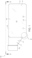
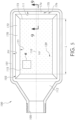
- FIG. 1 schematically illustrates a side view of a cell culture vessel 100 having a top 101, a bottom 108, and endwall 107, a neck 112 and an opening or aperture 105 shown in FIG. 1 covered by a cap 104.
- Each of the top 101, the bottom 108, the endwall 107 and the neck have interior surfaces. That is, the top 101 has an interior surface 201, the bottom has an interior surface 208, the neck 112 has an interior surface 212, the endwall 107 has an interior surface 207.
- the cell culture chamber 103 is that area of the vessel contained inside the interior surfaces of the vessel.
- the interior surface 208 of the bottom 108 has an array of microcavities 115.
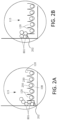
- FIG. 2A and FIG. 2B are schematic drawings of the area shown by circle “2" of FIG. 1 .
- FIG. 2A and 2B illustrate control vessels which result inhomogeneous cell culture. For example, if there are areas in the cell culture chamber 103, where cells may settle, where there are flat surfaces 202, cells 250 can congregate on flat surfaces instead of settling in the microcavities 120, and the cells can form irregular cellular conglomerates 801.
- cells may settle on the flat surfaces instead of settling into microcavities 120 as they fall through the media and settle on a surface. Examples of these uncontained irregular cellular conglomerates 801 are shown schematically in FIG. 2A and FIG. 2B . These cells can also invade neighboring microcavities and disrupt the culture of spheroids 250 contained in microcavities 120. In contrast, cells contained in microcavities 120 form regular, homogeneous spheroids 250 (see FIG. 18B , for example).
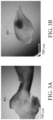
- FIG. 3A and 3B are photographs of irregular cellular conglomerations that formed on flat portions of cell culture vessels where these flat portions were present, according to Example 1, discussed below.
- the vessel 100 can include a cap 104 oriented to cover the aperture 105 to at least one of seal and block the aperture 105, thereby obstructing a path into the cell culture chamber 103 from outside the vessel 100 through the aperture 105 .
- the cap 104 is removed and, therefore, not shown in other drawing figures, although it is to be understood that the cap 104 can be provided and selectively added to or removed from the aperture 105 of the vessel 100, in some embodiments, without departing from the scope of the disclosure.
- the cap 204 can include a filter that permits the transfer of gas in to and/or out of the cell culture chamber 103 of the vessel 100.
- the cap 104 can include a gas-permeable filter oriented to regulate a pressure of gas within the cell culture chamber 103, thereby preventing pressurization (e.g., over-pressurization) of the cell culture chamber 103 relative to a pressure of the environment (e.g., atmosphere) outside the vessel 100.
- pressurization e.g., over-pressurization
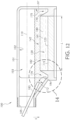
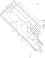
- e cell culture vessel 100 includes a flange 170 surrounding at least a portion of the array of microcavities 115.
- the array of microcavities 115 also referred to as "substrate” is made up of individual microcavities 120 (see FIG. 6-8 ). Therefore, unless otherwise noted, it is to be understood that, in embodiments, substrate 115 can include one or more features of the microcavities 120a, 120b, 120c (See FIG. 6-8 ).
- the cell culture vessel 100 includes a channel 175 surrounding at least a portion of the flange 170.
- Channel 175 has an opening 176.
- the flange 170 can surround all the microcavities of the array of microcavities 115. However, in some embodiments, the flange 170 can surround less than all (e.g., at least a portion of) the microcavities of the plurality of microcavities 120.
- the opening 176 of the channel 175 can surround the entire flange 170; however, in some embodiments, the opening 176 of the channel 175 can surround less than the entire flange 170 (e.g., at least a portion of) the flange 170. That is, the channel 175 may be closed in some areas, in embodiments.
- the flange 170 and/or the channel 175 can be formed (e.g., manufactured) as an integral component of cell culture vessel 100.
- the flange 170 and/or the channel 175 can be provided as a separate component that can be attached to the cell culture vessel 100 to, for example, retrofit an existing cell culture vessel, thereby providing the existing cell culture vessel with one or more features of the flange 170 and the channel 175 in accordance with embodiments of the disclosure.
- the array of microcavities 115 is integral to the interior surface 208 of the bottom 108 of the vessel. As shown in FIG.
- the array of microcavities may be provided by an insert, a separate material introduced to or affixed into the flask.
- a substrate having an array of microcavities 115 can be inserted into a cell culture vessel 100 and either rest on the bottom surface of the cell culture vessel or be affixed, by gluing, laser welding, ultrasonic welding, or some other method, to the bottom surface of the cell culture vessel.
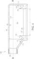
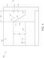
- FIG. 5 is a top-down view of the vessel, in embodiments.
- FIG. 5 illustrates that, in embodiments, the flange 170 surrounds the microcavity array 115, and the channel 175 surrounds the flange 170.
- FIG. 6-8 show an enlarged schematic representation of a portion of the cell culture vessel taken at view 6 of FIG. 5 , from a top-down perspective and from a cross-sectional perspective along line 7 of FIG. 6 (FIG. 7 and FIG. 8 ) showing a substrate having a plurality of microcavities 120 in accordance with embodiments of the disclosure.
- each microcavity 120a, 120b, 120c of the plurality of microcavities 120 includes a concave surface 121a, 121b, 121c (See FIG. 7 and FIG. 8 ) defining a well 122a, 122b, 122c.
- each microcavity 120a, 120b, 120c includes an opening 123a, 123b, 123c (e.g., in a first side 125 of the substrate 115) to allow liquid and cells to enter the microwells t 122a, 122b, 122c.
- the first side 125 of the substrate 115 can include a non-linear (e.g., undulating, sinusoidal) profile and a second side 126 of the substrate 115 can include a planar (e.g., flat) profile.
- both the first side 125 and the second side 126 of the substrate 115 can include a non-planar (e.g., undulating, sinusoidal) profile.
- providing both the first side 125 and the second side 126 of the substrate 115 with a non-planar (e.g., undulating, sinusoidal) profile can reduce the amount of material used to make the substrate 115 and can provide a substrate having a microcavity array 115 that includes thinner walled microcavities 120a, 120b, 120c than, for example, a substrate having a microcavity array 115, where the first side 125 of the substrate 115 includes a non-linear (e.g., undulating, sinusoidal) profile and the second side 126 of the substrate 115 includes a planar (e.g., flat) profile ( FIG. 7 ).
- a non-planar e.g., undulating, sinusoidal
- thinner walled microcavities 120a, 120b, 120c can permit a higher rate of gas transfer (e.g., permeability) of the substrate to provide more gas in to and out of the well 122a, 122b, 122c during cell culturing.
- gas transfer e.g., permeability
- providing both the first side 125 and the second side 126 of the substrate 115 with a non-planar (e.g., undulating, sinusoidal) profile FIG. 8
- the substrate 115 can include a polymeric material including, but not limited to, polystyrene, polymethylmethacrylate, polyvinyl chloride, polycarbonate, polysulfone, polystyrene copolymers, fluoropolymers, polyesters, polyamides, polystyrene butadiene copolymers, fully hydrogenated styrenic polymers, polycarbonate PDMS copolymers, and polyolefins such as polyethylene, polypropylene, polymethyl pentene, polypropylene copolymers and cyclic olefin copolymers.
- a polymeric material including, but not limited to, polystyrene, polymethylmethacrylate, polyvinyl chloride, polycarbonate, polysulfone, polystyrene copolymers, fluoropolymers, polyesters, polyamides, polystyrene butadiene copolymers, fully hydrogenated styrenic polymers,
- At least a portion of the well 122a, 122b, 122c defined by the concave surface 121a, 121b, 121c can be coated with an ultra-low binding material, thereby making the at least a portion of the well 122a, 122b, 122c non-adherent to cells.
- one or more of perfluorinated polymers, olefins, agarose, non- ionic hydrogels such as polyacrylamides, polyethers such as polyethyleneoxide, polyols such as polyvinylalcohol or mixtures thereof can be applied to at least a portion of the well 122a, 122b, 122c defined by the concave surface 121a, 121b, 121c.
- each microcavity 120a, 120b, 120c of the plurality of microcavities 120 can include a variety of features and variations of those features without departing from the scope of the disclosure.
- the plurality of microcavities 120 can be arranged in an array including a linear array (shown), a diagonal array, a rectangular array, a circular array, a radial array, a hexagonal close-packed arrangement, etc.
- the opening 123a, 123b, 123c can include a variety of shapes.
- the opening 123a, 123b, 123c can include one or more of a circle, an oval, a rectangle, a quadrilateral, a hexagon, and other polygonal shapes. Additionally, in some embodiments, the opening 123a, 123b, 123c can include a dimension (e.g., diameter, width, diagonal of a square or rectangle, etc.) from about 100 microns ( ⁇ m) to about 5000 ⁇ m.
- a dimension e.g., diameter, width, diagonal of a square or rectangle, etc.
- the opening 123a, 123b, 123c can include a dimension of 100 ⁇ m, 150 ⁇ m, 200 ⁇ m, 250 ⁇ m, 300 ⁇ m, 350 ⁇ m, 400 ⁇ m, 450 ⁇ m, 500 ⁇ m, 550 ⁇ m, 600 ⁇ m, 650 ⁇ m, 700 ⁇ m, 750 ⁇ m, 800 ⁇ m, 850 ⁇ m, 900 ⁇ m, 950 ⁇ m, 1000 ⁇ m, 1500 ⁇ m, 2000 ⁇ m, 2500 ⁇ m, 3000 ⁇ m, 3500 ⁇ m, 4000 ⁇ m, 4500 ⁇ m, 5000 ⁇ m, and any dimension or ranges of dimensions encompassed within the range of from about 100 ⁇ m to about 5000 ⁇ m.
- the well 122a, 122b, 122c defined by the concave surface 121a, 121b, 121c can include a variety of shapes. In some embodiments, the well 122a, 122b, 122c defined by the concave surface 121a, 121b, 121c can include one or more of a circular, elliptical, parabolic, hyperbolic, chevron, sloped, or other cross-sectional profile shape.
- a depth of the well 122a, 122b, 122c (e.g., depth from a plane defined by the opening 123a, 123b, 123c to the concave surface 121a, 121b, 121c can include a dimension from about 100 microns ( ⁇ m) to about 5000 ⁇ m.
- the depth of the well 122a, 122b, 122c can include a dimension of 100 ⁇ m, 150 ⁇ m, 200 ⁇ m, 250 ⁇ m, 300 ⁇ m, 350 ⁇ m, 400 ⁇ m, 450 ⁇ m, 500 ⁇ m, 550 ⁇ m, 600 ⁇ m, 650 ⁇ m, 700 ⁇ m, 750 ⁇ m, 800 ⁇ m, 850 ⁇ m, 900 ⁇ m, 950 ⁇ m, 1000 ⁇ m, 1500 ⁇ m, 2000 ⁇ m, 2500 ⁇ m, 3000 ⁇ m, 3500 ⁇ m, 4000 ⁇ m, 4500 ⁇ m, 5000 ⁇ m, any dimension or ranges of dimensions encompassed within the range of from about 100 ⁇ m to about 5000 ⁇ m.
- three-dimensional cells 150 that can be cultured in at least one microcavity 120a, 120b, 120c of the plurality of microcavities 120 can include a dimension (e.g., diameter) of from about 50 ⁇ m to about 5000 ⁇ m, and any dimension or ranges of dimensions encompassed within the range of from about 50 ⁇ m to about 5000 ⁇ m.
- dimensions greater than or less than the explicit dimensions disclosed can be provided and, therefore, unless otherwise noted, dimensions greater than or less than the explicit dimensions disclosed are considered to be within the scope of the disclosure.
- one or more dimensions of the opening 123a, 123b, 123c, the depth of the well 122a, 122b, 122c, and the dimension of the three-dimensional cells 150 can be greater than or less than the explicit dimensions disclosed without departing from the scope of the disclosure.
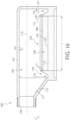
- the flange 170 can include an inner face 171 extending from the substrate 115 in a direction away from the concave surface 121a, 121b, 121c (See FIG. 6-8 ) of each microcavity 120a, 120b, 120c of the plurality of microcavities 120 to a perimeter 173 of the opening 176 of the channel 175.
- the inner face 171 can surround all the microcavities of the plurality of microcavities 120; however, in some embodiments, the inner face 171 can surround less than all (e.g., at least a portion of) the microcavities of the plurality of microcavities 120.
- the opening 176 of the channel 175 can surround the entire inner face 171; however, in some embodiments, the opening 176 of the channel 175 can surround less than the entire (e.g., at least a portion of) the inner face 171.
- the perimeter 173 of the opening 176 of the channel 175 can be spaced a distance "d8" from the portion 123 of the substrate 115 in a direction away from the concave surface 121a, 121b, 121c (See FIG. 6-8 ) of each microcavity 120a, 120b, 120c of the plurality of microcavities 120.
- the distance "d8" can be within a range of from about 2 millimeters (mm) to about 8 mm, for example, from about 4 mm to about 8 mm, although other values, (e.g., less than 2mm or greater than 8 mm) can be provided in other embodiments without departing from the scope of the disclosure.
- the perimeter 173 of the opening 176 of the channel 175 can be spaced a distance "d9" from the inner surface 102 of the wall 101 in a direction toward the portion 123 of the substrate 115.
- the opening 176 of the channel 175 can be defined between the inner surface 207 of the endwall 107 and the perimeter 173.
- the channel 175 can include an outer face 172 extending from the perimeter 173 of the opening 176 of the channel 175 in a direction toward the concave surface 121a, 121b, 121c (See FIG. 6-8 ) of each microcavity 120a, 120b, 120c of the plurality of microcavities 120 to a base 174 of the channel 175.
- the outer face 172 can surround all the microcavities of the plurality of microcavities 120; however, in some embodiments, the outer face 172 can surround less than all (e.g., at least a portion of) the microcavities of the plurality of microcavities 120.
- the base 174 of the channel 175 can surround the entire outer face 172; however, in some embodiments, the base 174 of the channel 175 can surround less than the entire (e.g., at least a portion of) the outer face 172.
- the method can include containing a predetermined amount of liquid 180 in a region 142 of the cell culture chamber 103 without liquid of the predetermined amount of liquid 180 contacting the channel 175.
- the region 142 can be defined based at least in part by the flange 170 and the substrate 115.
- the region 142 can be defined based at least in part by inner face 171 of the flange 170 and the portion 123 of the substrate 115.
- preventing liquid of the predetermined amount of liquid 180 from contacting the channel 175, at this stage of the method can provide several advantages that, for example, facilitate improved culturing of the cells 150.
- at least a portion of the predetermined amount of liquid 180 can include a culture solution or media including a liquid including solid particles (e.g., cells) suspended in the liquid.
- the method can include depositing liquid 140 of the predetermined amount of liquid 180 (See FIG.
- the structures of the array of microcavities 115 including the plurality of microcavities 120 are omitted from FIG. 10-17 with the understanding that, unless otherwise noted, in some embodiments, one or more features of the substrate 115 (See FIG. 6-8 ) can be provided alone or in combination with one or more features of the first exemplary cell culture vessel 100 without departing from the scope of the disclosure.
- the inner face 171 of the flange 170 can include a vertical orientation (e.g., extending substantially in the direction of gravity); however, in some embodiments, the inner face 171 can be inclined relative to the direction of gravity to, for example, direct cells toward the openings 123a, 123b, 123c of the microcavities 120a, 120b, 120c (See FIG. 6-8 ). Moreover, in some embodiments, the opening 123a of the microcavity 120a, for example, can be positioned to abut the inner face 171 of the flange 170.
- the opening 123a of the microcavity 120a can be flush with the inner face 171 of the flange 170 such that cells suspended in a liquid will fall (e.g., based at least on the force of gravity) and/or be directed by the inner face 171 into the reservoir 122a of the microcavity 120a without settling on or adhering to a surface of the vessel 100, including but not limited to the base 174 of the channel 175.
- cells that settle on or adhere to a surface of the vessel 100 can accumulate and grow (e.g., multiply) outside of the microcavities 120a, 120b, 120c causing problems with respect to desired growth of three-dimensional cells within the microcavities 120a, 120b, 120c.
- cells that do not fall (based at least on the force of gravity) into the reservoir 122a, 122b, 122c and that accumulate or attach to other surfaces of the vessel 100, including but not limited to the base 174 of the channel 175, can grow outside of the reservoir 122a, 122b, 122c and disrupt (e.g., discourage, alter, slow, or prevent) desired growth of three-dimensional cells within the reservoir 122a, 122b, 122c.
- cells that accumulate or attach to other surfaces of the vessel 100 can grow and dislodge three-dimensional cells in the reservoir 122a, 122b, 122c, thereby disrupting or destroying desired growth of three-dimensional cells within the reservoir 122a, 122b, 122c and altering desired size uniformity of the cells.
- all cells suspended within the liquid can be directed into the reservoirs 122a, 122b, 122c, thus reducing and eliminating problems that can otherwise occur if cells attach to surfaces of the vessel 100, outside the reservoirs 122a, 122b, 122c, including but not limited to the base 174 of the channel 175.
- the method can include depositing liquid 140 of the predetermined amount of liquid 180 (See FIG. 10 ) on the array of microcavities 115, surrounded by flange 170.
- the spheroids 150a, 150b, 150c can consume media (e.g., food, nutrients) and produce metabolite (e.g., waste) as a byproduct.
- media e.g., food, nutrients
- metabolite e.g., waste
- food media can be added to the cell culture chamber 103 during culturing and waste media can be removed from the cell culture chamber 103 during culturing.
- attempts can be made when adding and removing media to avoid displacing the spheroids 150a, 150b, 150c from the microcavities 120a, 120b, 120c and promote desired cell culturing of the spheroids 150a, 150b, 150c.
- three-dimensional cell culturing can consume more media (e.g., food, nutrients) and produce more media (e.g., waste) as a byproduct than, for example, a comparable two-dimensional cell culture.
- media e.g., food, nutrients
- media e.g., waste
- three-dimensional cell cultures in accordance with embodiments of the disclosure can include more frequent media exchanges (e.g., addition of food, nutrients and/or removal of waste) for a comparable period of time.
- three-dimensional cell cultures in accordance with embodiments of the disclosure can include larger media volumes (e.g., consume more food, nutrients and/or produce more waste) for a comparable period of time.
- one or more features of the cell culture vessel 100 and the methods of culturing cells 150 in the cell culture vessel 100 can provide advantages with respect to the frequency of media exchanges as well as the volume of media that can be one or more of contained within the cell culture chamber 103 of the vessel 100, added to the cell culture chamber 103, and removed from the cell culture chamber 103, thereby providing a desirable, effective environment in which to culture three-dimensional cells.
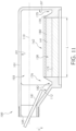
- the method can include adding material (e.g., food, nutrients) from outside the vessel 100 into the cell culture chamber 103 by inserting a dispensing-port 181 into the aperture 105 and dispensing material 182 from the dispensing-port into the opening 176 of the channel 175.
- material e.g., food, nutrients
- the method can include adding material (e.g., food, nutrients) from outside the vessel 100 into the cell culture chamber 103 by inserting a dispensing-port 181 into the aperture 105 and dispensing material 182 from the dispensing-port into the opening 176 of the channel 175 after containing the predetermined amount of liquid 180 in the region 142 of the cell culture chamber 103 without liquid of the predetermined amount of liquid 180 contacting the channel 175.
- the method can include culturing cells 150 in at least one microcavity 120 while dispensing material 182 from the dispensing-port 181 into the opening 176 of the channel 175.
- FIG. 12 schematically shows the material 182 added into the cell culture chamber 103 to, for example, provide the cells 150 included in the predetermined amount of liquid 180 with food media which the cells 150 can consume while being cultured.
- the method can include removing material (e.g., waste) from the cell culture chamber 103 to outside the vessel 100 by inserting a collecting-port 183 into the aperture 105 and collecting material 184 from the channel 175 with the collecting-port 183.
- the method can include removing material (e.g., waste) from the cell culture chamber 103 by inserting the collecting-port 183 into the aperture 105 and collecting material 184 from the channel 175 with the collecting-port 183 after adding material (e.g., food, nutrients) into the cell culture chamber 103.
- the method can include culturing cells 150 in at least one microcavity of the plurality of microcavities 120 (See FIG. 7 and 8 ) while collecting material 184 from the channel 175 with the collecting-port 183.
- FIG. 13 schematically shows material 184 removed from the cell culture chamber 103 to, for example, remove waste media, which the cells 150 can produce while being cultured, from the predetermined amount of liquid 180 and the material 182.
- the cells 150 can consume all or some of the food media (e.g., material 182) added to the cell culture chamber 103 and produce (e.g., metabolize as a byproduct) all or some of the waste media (e.g., material 184) removed from the cell culture chamber 103.
- the methods of adding food media 182 to the cell culture chamber 103 See FIG. 11 and FIG. 12
- removing waste media 184 from the cell culture chamber 103 See FIG.
- methods in accordance with embodiments of the disclosure of adding food media 182 to the cell culture chamber 103 (See FIG. 11 and FIG. 12 ) and removing waste media 184 from the cell culture chamber 103 (See FIG. 12 and FIG. 13 can, at least in part, increase one or more of the quality, duration, and effectiveness of the cell culturing process as compared to a cell culture environment to which food media is not added or from which waste media is not removed.
- one or more features of the vessel 100 as well as methods in accordance with embodiments of the disclosure of adding food media 182 to the cell culture chamber 103 See FIG. 11 and FIG.
- FIG. 12 and FIG. 13 can, at least in part, be performed more frequently and with greater effectiveness with respect to the volume of media that can be one or more of contained within the cell culture chamber 103 of the vessel 100, added to the cell culture chamber 103, and removed from the cell culture chamber 103 during the cell culturing process as compared to, for example, a cell culture vessel not including one or more features of the disclosure as well as methods not including one or more steps of the disclosure.
- the method can include moving the vessel 100 and collecting the material 184 from the channel 175 with the collecting-port 183.
- moving the vessel 100 can include at least one of translating and rotating the vessel 100 from a first orientation (e.g., the orientation provided in FIG. 13 ) to a second orientation (e.g., the orientation provided in FIG. 14 ).
- the first orientation e.g., the orientation provided in FIG. 13
- the first orientation can provide the vessel 100 with the axis 110 extending substantially perpendicular relative to the direction of gravity "g" although other orientations of the axis 110 relative to the direction of gravity "g" can be provided in other embodiments to define the first orientation.
- the second orientation (e.g., the orientation provided in FIG. 14 ) can provide the vessel 100 with the axis 110 extending at an angle that is substantially non-perpendicular relative to the direction of gravity "g" although other orientations of the axis 110 relative to the direction of gravity "g" can be provided in other embodiments to define the second orientation.
- the first orientation can provide the axis 110 at a first angle relative to the direction of gravity "g" that is different than a second angle of the axis 110 relative to the direction of gravity "g” provided by the second orientation.
- the axis 110 of the vessel 100 can extend substantially perpendicular to the direction of gravity "g" while one or more of containing the predetermined amount of liquid 180 in the region 142 of the cell culture chamber 103 (See FIG. 10 ), while adding material 182 to the cell culture chamber 103 (See FIG. 11 ), and while removing material 184 from the cell culture chamber 103 (See FIG. 12 and FIG. 13 ).
- the vessel 100 can be placed on, for example, a horizontal surface (not shown) that defines a major surface perpendicular to the direction of gravity "g" with the axis 110 of the vessel 100 extending substantially parallel to the major surface of the horizontal surface (not shown) relative to the direction of gravity "g".
- the vessel 100 can be supported (e.g., held, suspended) by one or more structures (e.g., frame, mount, human hand, etc.) with the axis 110 extending substantially perpendicular to the direction of gravity "g".
- the vessel 100 can be supported (e.g., held, suspended) by one or more structures (e.g., frame, mount, human hand, etc.) with the axis 110 extending at an angle that is substantially non-perpendicular relative to the direction of gravity "g" as a result of, for example, moving the vessel 100 (See FIG. 14 ) before and/or while collecting the material 184 from the channel 175 with the collecting-port 183.
- one or more structures e.g., frame, mount, human hand, etc.
- the method can include moving the vessel 100 to cause at least a portion of the predetermined amount of liquid 180 and the added material 182 (including waste material 184) to flow from the region 142 over the flange 170 (e.g., over the perimeter 173 of the opening 176 of the channel 175) and deposit in the channel 175.
- the vessel 100 can include moving the vessel 100 to cause at least a portion of the predetermined amount of liquid 180 and the added material 182 (including waste material 184) to flow from the region 142 over the flange 170 (e.g., over the perimeter 173 of the opening 176 of the channel 175) and deposit in the channel 175.
- the collecting-port 183 See FIG.
- At least a portion of the predetermined amount of liquid 180 and the added material 182 (including waste material 184) may remain within the region 142 of the cell culture chamber 103 based, at least in part, on the orientation of the vessel 100 and the presence of the flange 170 preventing at least the portion of the predetermined amount of liquid 180 and the added material 182 (including waste material 184) within the region 142 from flowing into the channel 175.
- the vessel 100 by moving the vessel 100 to cause at least a portion of the predetermined amount of liquid 180 and the added material 182 (including waste material 184) to flow from the region 142 over the flange 170 and deposit in the channel 175, removal of the waste material 184 can be controlled and, in some embodiments, increased relative to, for example, a method where the vessel 100 is not moved.
- the angle of the axis 110 relative to the direction of gravity "g" defined by the second orientation of the vessel 100 See FIG.
- the 14 can be selected to, for example, cause at least a portion of the predetermined amount of liquid 180 and the added material 182 (including waste material 184) to flow from the region 142 over the flange 170 and deposit in the channel 175 without causing cells 150 being cultured in the plurality of microcavities 120 from dislodging, thereby improving the cell culturing process.
- moving the vessel 100 in accordance with embodiments of the disclosure to cause at least a portion of the predetermined amount of liquid 180 and the added material 182 (including waste material 184) to flow from the region 142 over the flange 170 and deposit in the channel 175 as well as collecting the material 184 from the channel 175 with the collecting-port 183 can provide removal of all or at least a greater quantity of waste material 184 from the cell culture chamber 103, as compared to other methods, including but not limited to methods where the vessel 100 is not moved (e.g., remains stationary).
- the orientation of the axis 110 of the vessel 100 can remain unchanged during a duration of time while collecting the material 184 from the channel 175 with the collecting-port 183.
- the orientation of the axis 110 of the vessel 100 can change one or more times during a duration of time while collecting the material 184 from the channel 175 with the collecting-port 183.
- the method can include adding material (e.g., food, nutrients) into the cell culture chamber 103 by inserting the dispensing-port 181 into the aperture 105 and dispensing material 185 from the dispensing-port into the opening 176 of the channel 175 after removing material 184 (e.g., waste) from the cell culture chamber 103 (See FIG. 12-14 ).
- material 184 e.g., waste
- FIG. 15 schematically shows waste material 184 removed from the cell culture chamber 103 after collecting the material 184 from the channel 175 with the collecting-port 183 (See FIG.
- the added material 185 can, for example, replenish the cell culture environment with food and nutrients which the cells 150 have consumed and/or depleted.
- the material 182 and material 185 can include a same or similar composition or different compositions depending on, for example, the type of cell culturing being performed in the vessel 100.
- the methods of adding material 182 e.g., food, nutrients (See FIG. 11 and FIG.
- removing material 184 e.g., waste
- adding more material 185 e.g., food, nutrients
- FIG. 15 can be performed selectively one time or multiple times, while culturing cells 150, as the spheroids 150a, 150b, 150c continually (e.g., repeatedly) consume media (e.g., food, nutrients) and/or produce metabolite (e.g., waste) as a byproduct during the cell culturing process.
- media e.g., food, nutrients
- produce metabolite e.g., waste
- one or more features of the flange 170 and the channel 175 can provide advantages when adding and removing media (See FIG. 11-15 ) to avoid displacing the spheroids 150a, 150b, 150c from the microcavities 120a, 120b, 120c and promote desired cell culturing of the spheroids 150a, 150b, 150c (see FIG. 7 and 8 ).
- FIG. 16 illustrates an enlarged schematic representation of a portion of the cell culture vessel 100 taken at view 16 of FIG.
- FIG. 73 illustrates an enlarged schematic representation of a portion of the cell culture vessel 100 taken at view 73 of FIG. 68 including the method of removing material 184 (e.g., waste) from the cell culture chamber 103 by inserting the collecting-port 183 into the aperture 105 and collecting material 184 from the channel 175 with the collecting-port 183.
- material 185 e.g., food, nutrients
- FIG. 73 illustrates an enlarged schematic representation of a portion of the cell culture vessel 100 taken at view 73 of FIG. 68 including the method of removing material 184 (e.g., waste) from the cell culture chamber 103 by inserting the collecting-port 183 into the aperture 105 and collecting material 184 from the channel 175 with the collecting-port 183.
- the method of adding material 185 (e.g., food, nutrients) into the cell culture chamber 103 by inserting the dispensing-port 181 into the aperture 105 and dispensing material 185 from the dispensing-port into the opening 176 of the channel 175 can include obstructing the flow of material 185 along a first flow path 185a, 185b.
- the obstructing the flow along the first flow path 185a, 185b can include diverting the flow along the first flow path 185a, 185b with the flange 170.
- the diverting the flow along the first flow path 185a, 185b with the flange 170 can include, for example, filling the channel 175 with the material 185 along first flow path 185a, and then flowing the material 185 along first flow path 185b from the channel 175 into the region 142 of the cell culture chamber 103.
- the material 185 can be dispensed from the dispensing-port 181 into the opening 176 of the channel 175 to gradually fill the channel 175 with the material 185 along first flow path 185a from the base 174 of the channel 175 to the perimeter 173 of the opening 176 of the channel 175 along the outer face 172 of the channel 175.
- the material 185 can then flow over the perimeter 173 of the opening 176 of the channel 175 into the region 142 of the cell culture chamber 103 along first flow path 185b.
- At least a portion of the region 142 (defined based at least in part by the inner face 171 of the flange 170 and the portion 123 of the substrate 115) as well as at least a portion of the cell culture chamber 103 can gradually fill with the material 185 while the material 185 is dispensed from the dispensing-port 181 into the opening 176 of the channel 175.
- the region 142 (defined based at least in part by the inner face 171 of the flange 170 and the portion 123 of the substrate 115) as well as at least a portion of the cell culture chamber 103 can gradually fill with the material 182 while the material 182 is dispensed from the dispensing-port 181 into the opening 176 of the channel 175, as shown in FIG. 11 .
- the method of removing material (e.g., waste) from the cell culture chamber 103 by inserting the collecting-port 183 into the aperture 105 and collecting material 184 from the channel 175 with the collecting-port 183 can include obstructing the flow of material 184 along a second flow path 184a, 184b.
- the obstructing the flow along the second flow path 184a, 184b can include diverting the flow along the second flow path 184a, 184b with the flange 170.
- the diverting the flow along the second flow path 184a, 184b with the flange 170 can include, for example, removing the material 184 from the channel 175 along second flow path 184a, while flowing the material 184 along second flow path 184b.
- second flow path 184b can extend from the region 142 of the cell culture chamber 103 into the channel 175.
- second flow path 184b can extend from the cell culture chamber 103 (e.g., outside the region 142) into the channel 175.
- the material 184 can be collected from the channel 175 with the collecting-port 183 to gradually remove the material 184 from the channel 175 along the second flow path 184a, 184b. Additionally, in some embodiments, for example, after moving the vessel 100 to cause at least a portion of the predetermined amount of liquid 180 and the added material 182 (including waste material 184) to flow from the region 142 over the flange 170 and deposit in the channel 175 (See FIG. 14 ), the material 184 can be collected from the channel 175 with the collecting-port 183 to gradually remove the material 184 from the channel 175 along the second flow path 184a, 184b.
- material 184 can be gradually removed from the channel 175 along second flow path 184a from the perimeter 173 of the opening 176 of the channel 175 along the outer face 172 of the channel 175 to the base 174 of the channel 175. Accordingly, in some embodiments, the material 184 can be gradually removed from at least a portion of the cell culture chamber 103 as well as from at least a portion of the region 142 (defined based at least in part by the inner face 171 of the flange 170 and the portion 123 of the substrate 115) while the material 184 is collected with the collecting-port 183 from the channel 175.
- obstructing the flow of material 185 along the first flow path 185a, 185b with the flange 170 and obstructing the flow of material 184 along the second flow path 184a, 184b with the flange 170 can respectively add and remove material from the cell culture chamber 103 of the vessel 100 without, for example, interfering with the culturing of the cells 150. For example, as shown in FIG.
- the dispensing-port 181 can add material 185 to the cell culture chamber 103 by flowing (e.g., dispensing, blowing, aspirating) the material 185 from the dispensing-port 181 into the channel 175 with a velocity along the first flow path 185a, 185b, thereby creating a positive pressure force in and around the channel 175.
- the collecting-port 183 can remove material 184 from the cell culture chamber 103 by flowing (e.g., collecting, sucking) the material from the channel 175 into the collecting-port 183 with a velocity along the second flow path 184a, 184b, thereby creating a negative pressure force in and around the channel 175.
- the flange 170 can slow a velocity of the material 185, 184 respectively flowing along the first flow path 185a, 185b and the second flow path 184a, 184b, thereby respectively decreasing the positive pressure force and the negative pressure force in and around channel 175.
- the method of adding material (e.g., food, nutrients) into the cell culture chamber 103 by inserting the dispensing-port 181 into the aperture 105 and dispensing material 185 from the dispensing-port into the opening 176 of the channel 175 can provide a slow, continuous, and controlled (e.g., non-turbulent) flow of material 185 into the cell culture chamber 103 as compared to, for example, a method or cell culture vessel not including one or more features of the flange 170 and the channel 175.
- material e.g., food, nutrients
- the method of removing material (e.g., waste) from the cell culture chamber 103 by inserting the collecting-port 183 into the aperture 105 and collecting material 184 from the channel 175 can provide a slow, continuous, and controlled (e.g., non-turbulent) flow of material 184 out of the cell culture chamber 103 as compared to, for example, a method or cell culture vessel not including one or more features of the flange 170 and the channel 175.
- the flange 170 and the channel 175 can, therefore, prevent cells 150 being cultured in at least one microcavity 120a, 120b, 120c of the plurality of microcavities 115 from dislodging.
- one or more microcavities 120a, 120b, 120c can include more than one spheroid or no spheroids.
- the likelihood of dislodging cells 150 being cultured in the vessel 100 can be reduced and better quality cell cultures and more accurate scientific results relating to the cell cultures can be obtained.
- HCT116 a colon cancer cell line
- complete McCoy's 5a media (10% fetal bovine serum with 10 units/mL of penicillin/ 10ug/mL streptomycin) and trypsinized to detach the cells from the surface.
- the cells were then counted and resuspended in complete McCoy's media at a final concentration of cells at 1000 cells per microcavity (for T-75 microcavity flask add 15mL of cells at final concentration of ⁇ 6.5 x 10 ⁇ 5 cells/mL). Allow microcavity flask to sit at room temperature to allow for the cells to settle into the surface of the microcavity flask. After room temperature incubation, place flask in to 37°C incubator with 5% CO2 and 95% relative humidity for the duration of the experiment. Spheroid formation occurs within the first 24 hours.
- Control Flask HTC116 cells were seeded into a T75 flask that was prepared by cutting away the bottom surface of the flask and affixing material having an array of microcarriers to the bottom of the flask. Because the flask was cut away, a "lip" of material remained around the inner periphery of the bottom surface of the flask. This flat surface, around the periphery of the array of microcavities, was present during culture in the control vessel.
- HTC116 cells were also seeded into a T75 flask having the flange and channel structure illustrated in FIG. 4 and 5 , for example.
- flask After media with suspended cells were added to the inner area, flask was allowed to stay in static conditions for 15 min at room temperature to allow cells to settle into microwells. This 15 min incubation step is used in cell culture biology labs to ensure uniform cell seeding and to minimize edge effects upon subsequent placement of the vessels into incubator chamber. After cells settled into the microcavities, an additional amount of cell culture media was then added to the flask. In the control flask, media was added with a pipette to the mid-center of the bottom surface of the flask. In the experimental flask, media was added as shown, for example, in FIG. 16 . The flask was then placed into cell culture incubator and cultured for 14 days. During this culture period total of 7 media exchanges, with 90% media exchange efficiency, were performed.
- FIG. 18A is a photograph of spheroids growing in the control T75 flask. Spheroids are irregular and missing from some microcavities (having possibly been dislodged during media changes). In addition, irregular cellular conglomerates were seen in the control flask, such as those shown in FIG. 3A and 3B .
- FIG. 18B is a photograph showing spheroids in the experimental flask after 14 days of culture. Spheroids appear to be similar in size and all wells are filled with spheroids. Fig.18B demonstrates 100% spheroid retention in the flask assembled according to the experimental design with media changes.
- FIG. 19A and 19B are photographs of the harvested cells.
- FIG. 19A cells formed "ropes" of cells in vessels that had flat surfaces in the cell culture area (see white arrows). Other irregular cellular conglomerates can be seen in FIG. 19B .
- spheroids grown in the experimental flask according to FIG. 4 were regular and homogeneous, as shown in FIG. 19C and FIG. 19D .
- the terms “material”, “liquid”, and “gas” can be used to describe properties of a material employed when, for example, culturing cells in the cell culture vessel.
- material can include fluid material (e.g., liquid or gas).
- material can include a culture solution or media including a liquid including solid particles (e.g., cells) suspended in the liquid.
- liquid can include cleaning or rinsing solutions, aqueous solutions, or other liquid that can be added to or removed from the vessel to, for example, clean the cell culture chamber, sterilize one or more features of the substrate and the vessel, prepare the substrate for cellular growth and other uses of liquid.
- liquid can include a culture solution or media including a liquid including solid particles (e.g., cells) suspended in the liquid.
- gas can include air, filtered or treated air, or other gases.
- non-permeable gas-permeable
- porous can be used to describe properties (e.g., material properties, characteristics, parameters) of one or more features of a substrate.
- a non-permeable substrate e.g., material of a non-permeable substrate
- a non-permeable substrate is considered to be impermeable to solid, liquid, and gas under normal conditions (e.g., no external influence including but not limited to pressure and force) and, therefore, does not permit the transfer of solid, liquid, or gas in to, through, or out of, the non-permeable substrate under normal conditions.
- a non-permeable substrate can form a portion of the wall of the vessel.
- the cell culture chamber of the vessel is considered to be sterile when a non-permeable substrate forms a portion of the wall of the vessel because bacteria, for example, cannot pass through the non-permeable substrate.
- gas when filling the plurality of microcavities of the substrate with material, gas can become trapped within the microcavity of a non-permeable substrate based on surface tension of the liquid, thereby, in some embodiments, preventing material from filling the microcavities and preventing growth of a spheroid.
- a "gas-permeable" substrate e.g., material of a gas-permeable substrate
- a gas-permeable substrate does not permit the transfer of solid and liquid in to, through, or out of, the gas-permeable substrate and does permit the transfer of gas in to, through, or out of, the gas-permeable substrate.
- a gas-permeable substrate can form a portion of the wall of the vessel.
- the cell culture chamber of the vessel is considered to be sterile when a gas-permeable substrate forms a portion of the wall of the vessel because bacteria, for example, cannot reasonably pass through the gas-permeable substrate.
- the substrate is gas-permeable, gas can still become trapped in the microcavity during filling with material because gas-permeation rates through the gas-permeable substrate can be slower than the rate required to displace gas from the cavity under ordinary operating conditions and can therefore take an unacceptably long amount of time to permeate through the substrate.
- slowly filling the microcavities allows the liquid front to enter each microcavity at an angle, thereby displacing gas as the liquid fills the microcavity.
- gas after filling the cavity with liquid, gas can permeate (slowly) through the gas-permeable substrate.
- a porous substrate e.g., material of a porous substrate
- a porous substrate does not permit the transfer of solid in to, through, or out of, the porous substrate and does permit the transfer of liquid and gas in to, through, or out of, the porous substrate.
- a porous substrate cannot form a portion of the vessel because bacteria can pass through a porous substrate, thus causing sterility issues in the cell culture chamber.
- the substrate when using a porous substrate, the substrate must be enclosed (entirely enclosed) in the sterile cell culture chamber of the vessel.
- liquid can only pass through the porous substrate with added pressure or physical contact and disturbance of the substrate.
- material including liquid can be contained in the microcavities of the substrate so long as the substrate is not exposed to added pressure or physical contact and disturbance.
- the porous substrate can be supported in the cell culture chamber to allow gas to pass through the substrate during filling as well as during culturing and to isolated the substrate from added pressure or physical contact and disturbance from external forces (e.g., outside the cell culture chamber).
- Ranges can be expressed herein as from “about” one particular value, and/or to “about” another particular value. When such a range is expressed, embodiments include from the one particular value and/or to the other particular value. Similarly, when values are expressed as approximations, by use of the antecedent "about,” it will be understood that the particular value forms another aspect. It will be further understood that the endpoints of each of the ranges are significant both in relation to the other endpoint, and independently of the other endpoint.
Landscapes
- Health & Medical Sciences (AREA)
- Chemical & Material Sciences (AREA)
- Zoology (AREA)
- Life Sciences & Earth Sciences (AREA)
- Engineering & Computer Science (AREA)
- Bioinformatics & Cheminformatics (AREA)
- Organic Chemistry (AREA)
- Wood Science & Technology (AREA)
- Clinical Laboratory Science (AREA)
- General Health & Medical Sciences (AREA)
- Biomedical Technology (AREA)
- Sustainable Development (AREA)
- Biochemistry (AREA)
- General Engineering & Computer Science (AREA)
- Microbiology (AREA)
- Genetics & Genomics (AREA)
- Biotechnology (AREA)
- Analytical Chemistry (AREA)
- Hematology (AREA)
- Chemical Kinetics & Catalysis (AREA)
- Apparatus Associated With Microorganisms And Enzymes (AREA)
- Micro-Organisms Or Cultivation Processes Thereof (AREA)
Claims (9)
- Zellkulturgefäß (100), umfassend:eine Oberseite (101), eine Unterseite (108), Seitenwände (107, 111) und eine Halsöffnung (112);ein Substrat (115) auf der Unterseite (108) des Gefäßes (100), das eine Vielzahl von Mikrokavitäten (120) umfasst, wobei jede Mikrokavität (120a, 120b, 120c) der Vielzahl von Mikrokavitäten (120) eine Well-Öffnung (123a, 123b, 123c) und eine konkave Well-Unterseite (121a, 121b, 121c) umfasst; undeinen abgewinkelten Flansch (170), der mindestens einen Abschnitt (123) des Substrats (115) umgibt, um einen Umfang (173) an einer Oberseite des Flansches (170) zu definieren,wobei der Flansch (170) eine Innenfläche benachbart zu dem Abschnitt (123) des Substrats (115) und eine Außenfläche (172) gegenüber dem Abschnitt (123) des Substrats (115) aufweist; undwobei die Außenfläche (172) des Flansches (170) von dem Umfang (173) zu einer Basis (174) eines Kanals (175) abgewinkelt ist.
- Zellkulturgefäß (100) nach Anspruch 1, wobei das Substrat (115) an der Unterseite (108) des Gefäßes (100) befestigt ist.
- Zellkulturgefäß (100) nach Anspruch 1, wobei das Substrat (115) einstückig mit einer Unterseite (108) des Gefäßes (100) ist.
- Zellkulturgefäß (100) nach einem der vorhergehenden Ansprüche, wobei sich die Innenfläche (171) in einer vertikalen Richtung erstreckt.
- Zellkulturgefäß (100) nach Anspruch 1, ferner umfassend einen Kanal, der den Außenumfang des abgewinkelten Flansches (170) umgibt und eine Rinne um das Substrat (115) auf der Außenseite des Flansches (170) bildet.
- Zellkulturgefäß (100) nach Anspruch 2, ferner umfassend einen Kanal, der den Außenumfang des abgewinkelten Flansches (170) umgibt und eine Rinne um das Substrat (115) auf der Außenseite des Flansches (170) bildet.
- Zellkulturgefäß (100) nach Anspruch 3, ferner umfassend einen Kanal, der den Außenumfang des abgewinkelten Flansches (170) umgibt und eine Rinne um das Substrat (115) auf der Außenseite des Flansches (170) bildet.
- Verfahren zur Kultivierung von Zellen in dem Zellkulturgefäß (100) nach Anspruch 1, umfassend:Ablagern von Flüssigkeit in das Zellkulturgefäß (100) auf der Halsseite des Flansches (170);Füllen des Gefäßes mit Flüssigkeit, bis sich die Flüssigkeit über den Flansch (170) auf das Substrat (115) ergießt, das eine Vielzahl von Mikrokavitäten (120) umfasst; undKultivieren von Zellen in der Vielzahl von Mikrokavitäten (120).
- Verfahren nach Anspruch 8, ferner umfassend:Kippen des Zellkulturgefäßes (100) nach dem Kultivieren, um Zellflüssigkeit in dem Kanal anzusammeln;Einführen eines Auffanganschlusses in den Durchbruch des Behälters und Verwenden des Auffanganschlusses, um Flüssigkeit aus dem Kanal zu entfernen.
Applications Claiming Priority (5)
| Application Number | Priority Date | Filing Date | Title |
|---|---|---|---|
| US201762532639P | 2017-07-14 | 2017-07-14 | |
| US201762532648P | 2017-07-14 | 2017-07-14 | |
| US201762532671P | 2017-07-14 | 2017-07-14 | |
| US201862642400P | 2018-03-13 | 2018-03-13 | |
| PCT/US2018/042115 WO2019014610A1 (en) | 2017-07-14 | 2018-07-13 | CELL CULTURE CONTAINER FOR 3D CULTURE AND METHODS OF CULTURING 3D CELLS |
Publications (2)
| Publication Number | Publication Date |
|---|---|
| EP3652292A1 EP3652292A1 (de) | 2020-05-20 |
| EP3652292B1 true EP3652292B1 (de) | 2025-06-18 |
Family
ID=63078003
Family Applications (1)
| Application Number | Title | Priority Date | Filing Date |
|---|---|---|---|
| EP18749265.7A Active EP3652292B1 (de) | 2017-07-14 | 2018-07-13 | Zellkulturgefäss für 3d-kultur und verfahren zur kultivierung von 3d-zellen |
Country Status (6)
| Country | Link |
|---|---|
| US (1) | US11584906B2 (de) |
| EP (1) | EP3652292B1 (de) |
| JP (1) | JP7195302B2 (de) |
| CN (1) | CN111094536B (de) |
| PL (1) | PL3652292T3 (de) |
| WO (1) | WO2019014610A1 (de) |
Families Citing this family (4)
| Publication number | Priority date | Publication date | Assignee | Title |
|---|---|---|---|---|
| CN111655269A (zh) * | 2017-12-04 | 2020-09-11 | 杜雷安教育基金会行政处 | 使用球状体的细胞系统以及制造和使用它们的方法 |
| CN114502712A (zh) * | 2019-10-03 | 2022-05-13 | 康宁股份有限公司 | 制备可消化的球体稳定用水凝胶的试剂盒及方法 |
| EP4172307A1 (de) * | 2020-06-25 | 2023-05-03 | Corning Incorporated | Ultraschallvorrichtungen und verfahren zur verwendung |
| DE102021204675B4 (de) * | 2021-05-07 | 2023-05-17 | Lpkf Laser & Electronics Se | Vorrichtung und Verfahren zur Zellkultivierung |
Citations (1)
| Publication number | Priority date | Publication date | Assignee | Title |
|---|---|---|---|---|
| WO2016069892A1 (en) * | 2014-10-29 | 2016-05-06 | Corning Incorporated | Devices and methods for generation and culture of 3d cell aggregates |
Family Cites Families (248)
| Publication number | Priority date | Publication date | Assignee | Title |
|---|---|---|---|---|
| US2947116A (en) | 1954-02-26 | 1960-08-02 | Wilton R Earle | Method of producing tissue culture flasks |
| US3630849A (en) | 1969-04-24 | 1971-12-28 | David B Land | Surface micro-organism contamination assays |
| US4382685A (en) | 1979-07-17 | 1983-05-10 | Techne (Cambridge) Limited | Method and apparatus for stirring particles in suspension such as microcarriers for anchorage-dependent living cells in a liquid culture medium |
| DE8309876U1 (de) | 1983-04-02 | 1983-12-22 | Biotest-Serum-Institut Gmbh, 6000 Frankfurt | Zweiphasige blutkulturflasche |
| GB8321239D0 (en) | 1983-08-05 | 1983-09-07 | Orbec Ltd | Innoculating means |
| US4670396A (en) | 1985-05-02 | 1987-06-02 | Bioassy Systems Corporation | Vertical culture system with removable culture unit |
| US5171994A (en) | 1986-08-13 | 1992-12-15 | Northrop Corporation | Infrared staring imaging array |
| US5047347A (en) | 1987-08-17 | 1991-09-10 | Cline Martin J | Gas permeable culture flask and method for culturing mammalian cells |
| US4839292B1 (en) | 1987-09-11 | 1994-09-13 | Joseph G Cremonese | Cell culture flask utilizing membrane barrier |
| US4927764A (en) | 1987-11-17 | 1990-05-22 | Costar Corporation | Tissue culture flask |
| US4980293A (en) | 1988-09-02 | 1990-12-25 | Multi-Technology Inc. | Dispensing reagents in a specimen well |
| US5240854A (en) | 1989-06-05 | 1993-08-31 | Berry Eric S | Continuous high-density cell culture system |
| JP2850982B2 (ja) | 1989-10-25 | 1999-01-27 | ユニ・チャーム株式会社 | 使い捨て着用物品 |
| US5712137A (en) | 1990-03-05 | 1998-01-27 | Smith & Nephew Plc | Laminate of a culture substrate on a carrier for producing an apertured wound dressing |
| GB9004911D0 (en) | 1990-03-05 | 1990-05-02 | Smith & Nephew | Cell culture products |
| DE4030699C1 (de) | 1990-09-28 | 1991-10-10 | Bruker Analytische Messtechnik Gmbh, 7512 Rheinstetten, De | |
| US5272083A (en) | 1990-10-10 | 1993-12-21 | Costar Corporation | Culture device and method of use having a detachable cell or tissue growth surface |
| US5151366A (en) | 1991-05-24 | 1992-09-29 | Invitro Scientific Products, Inc. | Cell culture flask |
| DE4132379A1 (de) | 1991-09-28 | 1993-04-08 | Kernforschungsz Karlsruhe | Substrat fuer zellkulturen und kultur von zellen oder zellaggregaten |
| US5272084A (en) | 1991-12-18 | 1993-12-21 | Corning Incorporated | Cell culture vessels having interior ridges and method for cultivating cells in same |
| FR2697086B1 (fr) | 1992-10-20 | 1994-12-09 | Thomson Csf | Procédé et dispositif d'inspection de matériau transparent. |
| IT1266389B1 (it) | 1993-02-15 | 1996-12-30 | Alberto Degrassi | Struttura di contenitore, particolarmente per le colture cellulari |
| US5374557A (en) | 1993-04-29 | 1994-12-20 | Verma; Kuldeep | Fermentation vessels and closures therefor |
| DE69407923T2 (de) | 1993-05-17 | 1998-04-30 | Amersham Int Plc | Vorrichtung und verfahren zum nachweis zellularer und biochemischer prozesse |
| JP2716646B2 (ja) | 1993-05-21 | 1998-02-18 | 住友ベークライト株式会社 | 細胞凝集体の形成方法 |
| CN2186755Y (zh) | 1994-03-25 | 1995-01-04 | 中国科学院成都生物研究所 | 多用途培养板 |
| US5487872A (en) | 1994-04-15 | 1996-01-30 | Molecular Device Corporation | Ultraviolet radiation transparent multi-assay plates |
| US5707869A (en) | 1994-06-28 | 1998-01-13 | Wolf; Martin L. | Compartmentalized multiple well tissue culture plate |
| US5693537A (en) | 1994-06-28 | 1997-12-02 | Wilson; John R. | Compartmentalized tissue culture flask |
| US5635344A (en) | 1994-12-07 | 1997-06-03 | Cedra Corp. | Shipping medium for organ-derived cells |
| US5554536A (en) | 1995-01-05 | 1996-09-10 | Millipore Investment Holdings Limited | Biological analysis device having improved contamination prevention |
| GB9509487D0 (en) | 1995-05-10 | 1995-07-05 | Ici Plc | Micro relief element & preparation thereof |
| US5710043A (en) | 1995-09-25 | 1998-01-20 | Becton Dickinson And Company | In vitro cell culture assembly |
| US5759494A (en) | 1995-10-05 | 1998-06-02 | Corning Incorporated | Microplates which prevent optical cross-talk between wells |
| US5772905A (en) | 1995-11-15 | 1998-06-30 | Regents Of The University Of Minnesota | Nanoimprint lithography |
| FR2741357B1 (fr) | 1995-11-22 | 1998-01-16 | Corning Inc | Procede de fabrication d'une plaquette de support d'un reseau bidimensionnel de micropuits, notamment pour essais ou cultures biologiques |
| JPH09234811A (ja) | 1995-12-27 | 1997-09-09 | Mitsubishi Gas Chem Co Inc | フィルム状又はシート状の脱酸素多層体とその製造方法 |
| JPH09173049A (ja) | 1995-12-27 | 1997-07-08 | Sumitomo Bakelite Co Ltd | 培養用容器 |
| US5858309A (en) | 1996-03-22 | 1999-01-12 | Corning Incorporated | Microplates with UV permeable bottom wells |
| US5783440A (en) | 1996-09-30 | 1998-07-21 | Becton Dickinson And Company | Culture vessel |
| CN1234112A (zh) | 1996-10-10 | 1999-11-03 | 康宁股份有限公司 | 液滴传送工具和用该工具传送液滴的方法 |
| JP2001509272A (ja) | 1997-01-17 | 2001-07-10 | コーニング インコーポレイテッド | マルチウェルプレート |
| JPH10210966A (ja) | 1997-01-29 | 1998-08-11 | Sumitomo Bakelite Co Ltd | 培養容器 |
| JPH10210866A (ja) | 1997-01-30 | 1998-08-11 | Masayuki Minato | 強風でも倒れない植木鉢の転倒予防器具 |
| US5972694A (en) | 1997-02-11 | 1999-10-26 | Mathus; Gregory | Multi-well plate |
| US5859896A (en) | 1997-03-05 | 1999-01-12 | Rosen; Howard B. | Telephone line automatic prefix dialer |
| DE19712484C2 (de) | 1997-03-25 | 1999-07-08 | Greiner Gmbh | Microplatte mit transparentem Boden und Verfahren zu deren Herstellung |
| CH692583A5 (de) | 1998-03-03 | 2002-08-15 | Weidmann H Ag | Kulturgefäss. |
| DE19825812C1 (de) | 1998-06-09 | 2000-01-13 | Gsf Forschungszentrum Umwelt | Zellkulturgefäß für die Kultivierung nicht adhärenter Zellen |
| GB9812783D0 (en) | 1998-06-12 | 1998-08-12 | Cenes Ltd | High throuoghput screen |
| GB9912641D0 (en) | 1999-05-28 | 1999-07-28 | Ashby Scient Ltd | Textured and porous silicone rubber |
| JP4315544B2 (ja) | 1999-10-04 | 2009-08-19 | 日油株式会社 | 共重合体、その製造法、医療用材料及び眼科用材料 |
| US6521451B2 (en) | 1999-12-09 | 2003-02-18 | California Institute Of Technology | Sealed culture chamber |
| WO2003036265A2 (en) | 2001-10-26 | 2003-05-01 | Virtual Arrays, Inc. | Assay systems with adjustable fluid communication |
| DE10019862A1 (de) | 2000-04-18 | 2001-11-08 | Cell Lining Ges Fuer Zellkulti | Verfahren und Vorrichtung zur Automatisierung des Medienwechsels in Zellkulturen |
| EP1315567B1 (de) | 2000-04-19 | 2010-12-22 | Corning Incorporated | Mehrfachlochplatte und ihr herstellungsverfahren |
| DE10046175A1 (de) | 2000-09-19 | 2002-03-28 | Augustinus Bader | Verfahren und Vorrichtung zum Züchten und/oder Behandeln von Zellen |
| US6811752B2 (en) | 2001-05-15 | 2004-11-02 | Biocrystal, Ltd. | Device having microchambers and microfluidics |
| DE60215377T2 (de) | 2001-06-14 | 2007-08-23 | Millipore Corp., Billerica | Multiwell-Zellwachstumsvorrichtung |
| CA2351156A1 (en) | 2001-07-04 | 2003-01-04 | Peter W. Zandstra | A bioprocess for the generation of pluripotent cell derived cells and tissues |
| JP4111446B2 (ja) | 2001-07-26 | 2008-07-02 | 株式会社トランスパレント | 動物の培養細胞のスフェロイドを含む培養細胞構築物およびその使用 |
| US6767607B2 (en) | 2001-08-09 | 2004-07-27 | Corning Incorporated | Multiwell plate having transparent well bottoms |
| FR2830107B1 (fr) * | 2001-09-24 | 2004-09-24 | Gemplus Card Int | Cle electronique destinee a etre connectee a un port d'un dispositif de telecommunication et procede de fabrication de la cle |
| JP2003135056A (ja) | 2001-10-30 | 2003-05-13 | Mitsuo Ochi | 移植用組織等価物の製造方法及びその製造用器具 |
| JP2003180335A (ja) | 2001-12-21 | 2003-07-02 | Sumitomo Bakelite Co Ltd | 収納培養容器 |
| AU2003202323B2 (en) | 2002-02-12 | 2007-11-22 | Cgg Data Services Ag | Airborne vector magnetic surveys |
| AU2003265228A1 (en) | 2002-03-12 | 2003-12-22 | Surface Logix, Inc. | Assay device that analyzes the absorption, metabolism, permeability and/or toxicity of a candidate compound |
| US20050147959A1 (en) | 2002-03-25 | 2005-07-07 | Frondoza Carmelita G. | Tissue analogs for in vitro testing and method of use therefor |
| US20030183958A1 (en) | 2002-03-28 | 2003-10-02 | Becton, Dickinson And Company | Multi-well plate fabrication |
| ATE360057T1 (de) | 2002-09-20 | 2007-05-15 | Becton Dickinson Co | Rollflasche |
| JP3764959B2 (ja) * | 2002-10-10 | 2006-04-12 | 独立行政法人理化学研究所 | 細胞培養用容器および細胞培養方法 |
| EP2233564A3 (de) | 2002-10-30 | 2012-11-21 | Hitachi, Ltd. | Zellkulturträger umfassend ein funktionelles Substrat mit einer Gruppe kolumnarer Mikrosäulen und Herstellverfahren hierfür |
| US20040091397A1 (en) | 2002-11-07 | 2004-05-13 | Corning Incorporated | Multiwell insert device that enables label free detection of cells and other objects |
| FI115060B (fi) | 2003-04-22 | 2005-02-28 | Chip Man Technologies Oy | Analyysi- ja kasvatuslaitteisto |
| US20060252044A1 (en) | 2003-04-25 | 2006-11-09 | Jsr Corporation | Biochip and biochip kit, and method of producing the same and method of using the same |
| US7425440B2 (en) | 2003-06-10 | 2008-09-16 | The Automation Partnership (Cambridge) Limited | Culture flask |
| US20050032208A1 (en) | 2003-06-18 | 2005-02-10 | Oh Steve Kah Weng | Materials and methods to produce stem cells |
| US8597597B2 (en) | 2003-06-26 | 2013-12-03 | Seng Enterprises Ltd. | Picoliter well holding device and method of making the same |
| EP1644486B1 (de) | 2003-07-08 | 2014-09-10 | Axiogenesis Ag | Neue methode zur herstellung sogenannter embryoid bodies (ebs) und deren anwendung |
| US20050112030A1 (en) | 2003-08-21 | 2005-05-26 | Gaus Stephanie E. | Meshwell plates |
| WO2005035728A2 (en) | 2003-10-08 | 2005-04-21 | Wilson Wolf Manufacturing Corporation | Cell culture methods and devices utilizing gas permeable materials |
| US8658349B2 (en) | 2006-07-13 | 2014-02-25 | Seahorse Bioscience | Cell analysis apparatus and method |
| US7186548B2 (en) | 2003-11-10 | 2007-03-06 | Advanced Pharmaceutical Sciences, Inc. | Cell culture tool and method |
| JP2007515958A (ja) | 2003-12-19 | 2007-06-21 | ユニヴァーシティー オブ ウォータールー | 培養細胞、細胞培養の方法および機器 |
| ES2456015T3 (es) | 2004-03-05 | 2014-04-21 | Dsm Ip Assets B.V. | Procedimiento para cultivar células mediante perfusión continua y flujo tangencial alternante |
| US8318479B2 (en) | 2004-05-19 | 2012-11-27 | Massachusetts Institute Of Technology | Perfused three-dimensional cell/tissue disease models |
| WO2006019836A1 (en) | 2004-07-22 | 2006-02-23 | Corning Incorporated | Culture flask |
| US7767446B2 (en) | 2004-09-16 | 2010-08-03 | Becton, Dickinson And Company | Perfusion bioreactors for culturing cells |
| WO2006043267A1 (en) | 2004-10-18 | 2006-04-27 | Seng Enterprises Ltd. | Current damper for the study of cells |
| JP3981929B2 (ja) | 2004-10-29 | 2007-09-26 | 財団法人北九州産業学術推進機構 | 細胞組織体マイクロチップ |
| EP2161567A1 (de) | 2004-11-24 | 2010-03-10 | Asahi Glass Company, Limited | Verfahren und Vorrichtung zur Inspektion eines Defekts eines durchsichtigen Plattenkörpers |
| JP4672376B2 (ja) | 2005-01-11 | 2011-04-20 | 株式会社クラレ | 伸展方向が制御された細胞の培養方法 |
| GB2427688A (en) | 2005-06-28 | 2007-01-03 | Inogen S A | Microwell plate |
| US7829581B2 (en) | 2005-07-15 | 2010-11-09 | Laboratorios Del Dr. Esteve, S.A. | Prodrugs of pyrazoline compounds, their preparation and use as medicaments |
| US7745209B2 (en) | 2005-07-26 | 2010-06-29 | Corning Incorporated | Multilayered cell culture apparatus |
| DE202006020796U1 (de) | 2005-08-01 | 2010-06-24 | Life Technologies Corp., Carlsbad | Behälter |
| BE1016793A4 (fr) * | 2005-10-04 | 2007-06-05 | Artelis | Procede de culture de cellules et dispositif permettant sa mise en oeuvre. |
| JP5039715B2 (ja) | 2006-01-24 | 2012-10-03 | ブラウン ユニバーシティ | 細胞凝集及び封入デバイス及び方法 |
| JP4159103B2 (ja) | 2006-02-21 | 2008-10-01 | Scivax株式会社 | 細胞培養構造体、細胞培養容器、スフェロイド付き構造体、スフェロイド付き容器およびこれらの製造方法 |
| EP1988153B1 (de) | 2006-02-24 | 2019-06-19 | Corning Incorporated | Zellkulturbehälter und verfahren zur herstellung davon |
| ITMI20061063A1 (it) | 2006-05-31 | 2007-12-01 | Mindseeds Lab S R L | Metrodo e apparato pe rla selezione e la modifica di singole cellule e loro piccoli aggregati |
| DE102006030068A1 (de) | 2006-06-28 | 2008-01-03 | M2P-Labs Gmbh | Vorrichtung und Verfahren zur Zu- und Abfuhr von Fluiden in geschüttelten Mikroreaktoren Arrays |
| US7745210B2 (en) | 2006-06-30 | 2010-06-29 | Corning Incorporated | Fluid flow diverter for cell culture vessel |
| US9175254B2 (en) | 2006-07-07 | 2015-11-03 | University Of Miami | Enhanced oxygen cell culture platforms |
| CA2657232A1 (en) | 2006-07-07 | 2008-01-10 | University Of Miami | Enhanced oxygen cell culture platforms |
| US8053230B2 (en) | 2006-09-07 | 2011-11-08 | Nalge Nunc International Corporation | Culture dish with lid |
| EP2126037A1 (de) | 2006-11-14 | 2009-12-02 | Acme Biosystems, LLC | Zellkulturgerät und relevante verfahren |
| US20080118974A1 (en) | 2006-11-20 | 2008-05-22 | Gregory Roger Martin | Large scale cell culture vessel |
| DE202006017853U1 (de) | 2006-11-23 | 2007-01-18 | Forschungszentrum Karlsruhe Gmbh | Einsatz für eine Mikrotiterplatte |
| JP2010512149A (ja) | 2006-12-07 | 2010-04-22 | ウィルソン ウォルフ マニュファクチャリング コーポレイション | 細胞培養に効果的な装置および方法 |
| US7897379B2 (en) | 2007-02-26 | 2011-03-01 | Corning Incorporated | Device and method for reducing bubble formation in cell culture |
| WO2008106771A1 (en) | 2007-03-02 | 2008-09-12 | Mark Ungrin | Devices and methods for production of cell aggregates |
| WO2008118500A1 (en) | 2007-03-27 | 2008-10-02 | Wafergen, Inc. | Nutrient perfusion plate with heater & gas exchange for high content screening |
| KR100836827B1 (ko) | 2007-04-09 | 2008-06-10 | 전남대학교산학협력단 | 배아줄기세포의 배상체 형성용 배양용기 |
| WO2008140295A1 (en) | 2007-05-16 | 2008-11-20 | Erasmus University Medical Center Rotterdam | Cell culture substrate, culture flasks and methods for cell cultivation employing said substrate |
| DE102007027273A1 (de) | 2007-05-24 | 2008-11-27 | Heipha Gmbh | Behältnis zur Aufnahme von Nährmedien |
| FR2916451A1 (fr) | 2007-05-25 | 2008-11-28 | Mhs Ind Soc Par Actions Simpli | Systeme de culture de cellules biologiques |
| US9309491B2 (en) | 2007-05-29 | 2016-04-12 | Corning Incorporated | Cell culture apparatus for co-culture of cells |
| US7800749B2 (en) | 2007-05-31 | 2010-09-21 | Corning Incorporated | Inspection technique for transparent substrates |
| WO2009006422A1 (en) | 2007-06-29 | 2009-01-08 | Stem Cell Products, Inc. | Automated method and apparatus for embryonic stem cell culture |
| JP5233187B2 (ja) | 2007-07-11 | 2013-07-10 | パナソニック株式会社 | 細胞電気生理センサ |
| JP2009050194A (ja) | 2007-08-27 | 2009-03-12 | Sumitomo Bakelite Co Ltd | 細胞凝集塊形成培養用容器 |
| JP3139350U (ja) | 2007-11-27 | 2008-02-14 | 株式会社クラレ | 細胞培養容器 |
| EP2933325B1 (de) | 2008-01-25 | 2019-09-25 | Corning Incorporated | Verteiler für mehrschichtiges zellkultursystem mit begrenztem zugang |
| DE602008002545D1 (de) | 2008-02-01 | 2010-10-28 | Eppendorf Ag | Kulturplatte mit Klappe zur seitlichen Belüftung |
| US20100112014A1 (en) | 2008-04-11 | 2010-05-06 | Gilbert Ryan J | Novel hydrogel compositions and methods of using |
| CN102046773A (zh) | 2008-05-30 | 2011-05-04 | 康宁股份有限公司 | 具有不同微孔外形的细胞培养装置 |
| CN102105578A (zh) | 2008-05-30 | 2011-06-22 | 康宁股份有限公司 | 具有可变表面形状的细胞培养装置 |
| US8178345B2 (en) | 2008-05-30 | 2012-05-15 | Corning Incorporated | Multilayer cell culture vessels |
| US8216828B2 (en) | 2008-05-30 | 2012-07-10 | Corning Incorporated | Assembly of cell culture vessels |
| WO2010006055A2 (en) | 2008-07-08 | 2010-01-14 | Wilson Wolf Manufacturing Corporation | Improved gas permeable cell culture device and method of use |
| WO2010008566A2 (en) | 2008-07-16 | 2010-01-21 | Millipore Corporation | A single or multitier cell culture system |
| US9126199B2 (en) | 2008-09-22 | 2015-09-08 | Universitat Zurich Prorektorat Forschung | Hanging drop plate |
| JP5578779B2 (ja) | 2008-10-08 | 2014-08-27 | 国立大学法人東北大学 | スフェロイド培養方法及びスフェロイド培養容器 |
| US9249383B2 (en) | 2008-10-08 | 2016-02-02 | Agency For Science Technology & Research | Apparatus for culturing anchorage dependent cells |
| JP5288171B2 (ja) | 2008-10-31 | 2013-09-11 | 旭硝子株式会社 | 培養用容器 |
| EP2361302A4 (de) | 2008-11-05 | 2013-10-16 | Nanopoint Inc | Aktivmikrofluidsystem für in-vitro-kulturen |
| US8956867B2 (en) | 2008-11-07 | 2015-02-17 | Wisconsin Alumni Research Foundation | Method for culturing stem cells |
| ES2343721B1 (es) | 2008-12-19 | 2011-06-06 | Histocell, S.L. | Sistema de transporte de celulas. |
| JP2010158214A (ja) | 2009-01-09 | 2010-07-22 | Olympus Corp | 培養容器 |
| DE102009005526A1 (de) | 2009-01-20 | 2010-07-22 | Universität Duisburg-Essen | Bioreaktor und Verfahren zur Biomasseerzeugung |
| US20120064627A1 (en) | 2009-01-26 | 2012-03-15 | The Regents Of The University Of California | Apparatus and method for culturing stem cells |
| US8163537B2 (en) | 2009-01-27 | 2012-04-24 | Corning Incorporated | Nested permeable support device and method for using the nested permeable support device |
| DE102009013673A1 (de) | 2009-03-09 | 2010-09-16 | Eppendorf Ag | Zellkulturschale |
| US20120129208A1 (en) | 2009-03-18 | 2012-05-24 | Michelle Khine | Honeycomb shrink wells for stem cell culture |
| WO2010110754A1 (en) | 2009-03-26 | 2010-09-30 | Agency For Science, Technology And Research | Apparatus for cell or tissue culture |
| JP2012527217A (ja) | 2009-04-24 | 2012-11-08 | ジ・オハイオ・ステート・ユニバーシティ | 双方向微小環境系 |
| US9169460B2 (en) | 2009-05-19 | 2015-10-27 | Lifeglobal Group Llc | Flooding dish and method for changing media in the dish in the preparation of mammalian specimen culture and for cryo-preservation, freezing, vitrification and the thawing and warming of such specimens |
| US8778669B2 (en) | 2009-07-22 | 2014-07-15 | Corning Incorporated | Multilayer tissue culture vessel |
| US8143053B2 (en) | 2009-10-26 | 2012-03-27 | Biomerieux, Inc. | Lockable cell growth chamber with antilocking feature |
| US20120219572A1 (en) | 2009-11-12 | 2012-08-30 | Prockop Darwin J | Spheroidal Aggregates of Mesenchymal Stem Cells |
| EP2522716B1 (de) | 2010-01-08 | 2019-08-28 | Sumitomo Bakelite Company Limited | Kulturgefäss zur bildung einer aggregierten zellmasse |
| US9493733B2 (en) | 2010-01-18 | 2016-11-15 | Becton, Dickinson And Company | Container assembly |
| US8906685B2 (en) | 2010-01-28 | 2014-12-09 | The Regents Of The University Of Michigan | Hanging drop devices, systems and/or methods |
| CN201626959U (zh) | 2010-02-01 | 2010-11-10 | 中国农业科学院北京畜牧兽医研究所 | 用于细胞培养的微灌流装置 |
| JP2011172533A (ja) | 2010-02-25 | 2011-09-08 | Fusao Komada | マイクロ空間構造体を用いた高密度三次元細胞培養法 |
| SG185113A1 (en) | 2010-05-04 | 2012-12-28 | Agency Science Tech & Res | A microsieve for cells and particles filtration |
| WO2012032844A1 (ja) | 2010-09-08 | 2012-03-15 | 株式会社島津製作所 | 細胞培養容器及びその容器を用いた細胞培養方法 |
| SG188505A1 (en) | 2010-09-14 | 2013-05-31 | Asahi Glass Co Ltd | Culture substrate |
| US9260684B1 (en) | 2010-11-11 | 2016-02-16 | Stemcell Technologies Inc. | Cell culture device |
| KR20130140058A (ko) | 2010-12-09 | 2013-12-23 | 아사히 가라스 가부시키가이샤 | 유리 리본 내 결함 측정 방법 및 유리 리본 내 결함 측정 시스템 |
| CA2825553A1 (en) | 2011-01-24 | 2012-08-02 | California Stem Cell, Inc. | Neural cell purification for transplantation |
| TWI438273B (zh) | 2011-03-08 | 2014-05-21 | Univ Chang Gung | High-throughput perfusative microfluidic cell culture wafers for miniaturized three-dimensional cell culture |
| GB201105226D0 (en) | 2011-03-29 | 2011-05-11 | Univ Leiden | Methods |
| BR112013024976A2 (pt) | 2011-03-30 | 2016-08-16 | Nat Ct Geriatrics & Gerontology | dispositivo e kit de cultura de separação por membrana, método para separar células-tronco, membrana de separação, métodos para produzir a membrana de separação, de modificação, e para modificar a superfície de um corpo moldado |
| JP2012249547A (ja) | 2011-05-31 | 2012-12-20 | Oji Holdings Corp | 細胞培養用基材及びその製造方法 |
| WO2012170232A1 (en) | 2011-06-09 | 2012-12-13 | Bellbrook Labs, Llc | Device for washing suspended cells or particles |
| JP5853512B2 (ja) | 2011-09-08 | 2016-02-09 | 大日本印刷株式会社 | 細胞培養容器とその製造方法 |
| KR101306289B1 (ko) | 2011-09-15 | 2013-09-09 | (주) 인텍플러스 | 평판 패널 검사방법 |
| US10655107B2 (en) | 2011-09-20 | 2020-05-19 | Corning Incorporated | Adherent cell culture method |
| US9200246B2 (en) | 2011-12-01 | 2015-12-01 | Acea Biosciences, Inc. | Co-culture device assembly |
| EP2806261B1 (de) | 2012-01-19 | 2019-06-05 | Yamaha Hatsudoki Kabushiki Kaisha | Vertiefungsplatte und saugvorrichtung mit dieser vertiefungsplatte |
| WO2013116449A1 (en) | 2012-02-02 | 2013-08-08 | Corning Incorporated | Automatic continuous perfusion cell culture microplate consumables |
| CN202450098U (zh) | 2012-03-09 | 2012-09-26 | 山东省农业科学院畜牧兽医研究所 | 一种用于组织块培养细胞的培养瓶 |
| EP2653531A1 (de) | 2012-04-18 | 2013-10-23 | Oxyphen AG | Kulturanordnung |
| US20140004086A1 (en) | 2012-06-29 | 2014-01-02 | Tissue Genesis Inc. | Formation of cell aggregates |
| JP6111673B2 (ja) | 2012-07-25 | 2017-04-12 | 住友電気工業株式会社 | 炭化珪素半導体装置 |
| USD685497S1 (en) | 2012-08-31 | 2013-07-02 | Corning Incorporated | Cell culture flask |
| US9573128B1 (en) | 2012-09-06 | 2017-02-21 | SciKon Innovation, Inc. | Fluidics device allowing fluid flow between a plurality of wells |
| EP2896684A4 (de) | 2012-09-14 | 2015-12-23 | Sumitomo Bakelite Co | Mikrotiterplatte |
| CN202849407U (zh) | 2012-09-26 | 2013-04-03 | 无锡耐思生物科技有限公司 | 一种细胞培养瓶结构 |
| US9701938B2 (en) | 2012-10-12 | 2017-07-11 | Lena Biosciences, Inc. | Intra-culture perfusion methods and applications thereof |
| KR20140048733A (ko) | 2012-10-16 | 2014-04-24 | 삼성전자주식회사 | 다중 웰 플레이트 및 상기 다중 웰 플레이트를 이용한 표적 물질 분석 방법 |
| US9176115B2 (en) | 2012-10-26 | 2015-11-03 | The University Of Akron | Engineering individually addressable cellular spheroids using aqueous two-phase systems |
| GB2507744A (en) | 2012-11-07 | 2014-05-14 | Universitaetsklinikum Freiburg | Matrix for generating and cultivating uniform cell aggregations |
| CN104471052B (zh) | 2012-11-13 | 2017-06-13 | 海马生物科学公司 | 用于基于控制介质流动的三维组织测量的装置和方法 |
| JP2014132869A (ja) | 2013-01-11 | 2014-07-24 | Sumitomo Bakelite Co Ltd | 細胞培養容器 |
| US10072241B2 (en) | 2013-03-13 | 2018-09-11 | Innovative Surface Technologies, Inc. | Conical devices for three-dimensional aggregate(s) of eukaryotic cells |
| EP2781591B1 (de) | 2013-03-19 | 2017-05-03 | Unisense Fertilitech A/S | Schale, System und Verfahren zur Überwachung und Kultivierung einer Zellkultur |
| KR20140113139A (ko) | 2013-03-15 | 2014-09-24 | 고려대학교 산학협력단 | 세포 스페로이드 배양판 |
| JPWO2014156455A1 (ja) | 2013-03-28 | 2017-02-16 | 富士フイルム株式会社 | 細胞培養用具 |
| USD748812S1 (en) | 2013-04-12 | 2016-02-02 | Corning Incorporated | Arched cell culture flask |
| KR102234887B1 (ko) | 2013-04-19 | 2021-04-01 | 주식회사 에이엔케이 | 세포배양 기판 |
| US9790465B2 (en) | 2013-04-30 | 2017-10-17 | Corning Incorporated | Spheroid cell culture well article and methods thereof |
| WO2014197550A1 (en) | 2013-06-05 | 2014-12-11 | David Kranbuehl | Multi point method and apparatus for monitoring the aging and changes in corresponding tensile performance properties of a polymer |
| JPWO2014196204A1 (ja) | 2013-06-07 | 2017-02-23 | 株式会社クラレ | 培養容器及び培養方法 |
| JP6307802B2 (ja) | 2013-07-05 | 2018-04-11 | 株式会社Ihi | 培養容器 |
| JP2015029431A (ja) | 2013-07-31 | 2015-02-16 | 大日本印刷株式会社 | 細胞培養容器 |
| CN203513696U (zh) | 2013-08-27 | 2014-04-02 | 浙江硕华医用塑料有限公司 | 细胞培养瓶 |
| DE102013109450B4 (de) | 2013-08-30 | 2015-04-02 | Fraunhofer-Gesellschaft zur Förderung der angewandten Forschung e.V. | Expositionsapparat |
| PL3041926T3 (pl) | 2013-09-05 | 2020-11-02 | Universität Bern | Urządzenie do modelowania in-vitro tkanek organów in-vivo |
| JP2015050964A (ja) | 2013-09-06 | 2015-03-19 | 住友ベークライト株式会社 | 多段式培養フラスコおよび細胞培養フラスコの製造方法 |
| JP6185816B2 (ja) | 2013-10-11 | 2017-08-23 | Agcテクノグラス株式会社 | 細胞培養容器 |
| AU2014344726B2 (en) | 2013-10-30 | 2019-01-17 | Milica Radisic | Devices and methods for three-dimensional tissue culturing |
| WO2015087369A1 (ja) | 2013-12-12 | 2015-06-18 | ヤマハ発動機株式会社 | ウェルプレート、該ウェルプレートを備えた対象物選別装置 |
| WO2015134550A1 (en) | 2014-03-03 | 2015-09-11 | Kiyatec Inc. | 3d tissue culture devices and systems |
| WO2015132729A1 (en) | 2014-03-04 | 2015-09-11 | Pluristem Ltd. | Systems and methods for growing and harvesting cells |
| JP6386258B2 (ja) * | 2014-06-16 | 2018-09-05 | 日東電工株式会社 | 細胞培養用シートおよびその製造方法 |
| DE102014214077A1 (de) | 2014-07-18 | 2016-01-21 | Hamilton Bonaduz Ag | Laborbehälter, insbesondere Zellkulturbehälter, mit einer in das Behältervolumen hinein verlaufenden Gas-Ausgleichsleitung |
| EP2985343A1 (de) | 2014-08-11 | 2016-02-17 | Karlsruher Institut für Technologie | In-vitro-Co-Kultursystem |
| WO2016064757A1 (en) | 2014-10-19 | 2016-04-28 | Nortis, Inc. | Modular microfluidic system for perfused cell culture |
| US20170342363A1 (en) * | 2014-10-29 | 2017-11-30 | Corning Incorporated | Devices and methods for generation and culture of 3d cell aggregates |
| JP2017532971A (ja) | 2014-10-29 | 2017-11-09 | コーニング インコーポレイテッド | 細胞培養集合体を生成するためのマイクロウェル設計および製造 |
| SG11201703498WA (en) * | 2014-10-29 | 2017-05-30 | Corning Inc | Spheroid trap insert |
| WO2016069895A1 (en) | 2014-10-29 | 2016-05-06 | Corning Incorporated | Cell culture insert |
| EP3212760A1 (de) | 2014-10-29 | 2017-09-06 | Corning Incorporated | Perfusionsbioreaktorplattform |
| JP2016093149A (ja) * | 2014-11-14 | 2016-05-26 | 真志 池内 | 細胞培養装置および細胞培養方法 |
| DE102014017728B4 (de) | 2014-12-01 | 2025-04-30 | Merck Patent Gmbh | Kulturschale für Mikrooganismen |
| JP2016136920A (ja) | 2015-01-29 | 2016-08-04 | 大日本印刷株式会社 | 細胞培養容器 |
| JP2016136921A (ja) | 2015-01-29 | 2016-08-04 | 大日本印刷株式会社 | 細胞培養容器 |
| CN204752742U (zh) | 2015-03-12 | 2015-11-11 | 广州医科大学 | 一种可用于慢生长细胞培养的细胞培养皿 |
| CN204702760U (zh) | 2015-04-15 | 2015-10-14 | 上海诺狄生物科技有限公司 | 一种培养皿 |
| CN204714819U (zh) | 2015-04-21 | 2015-10-21 | 北京青藤谷禧干细胞科技研究院有限公司 | 一种带支架的细胞培养瓶 |
| CN204608026U (zh) | 2015-04-22 | 2015-09-02 | 广州洁特生物过滤股份有限公司 | 一种具有超亲水生长表面的细胞嵌入皿 |
| CN204803327U (zh) | 2015-06-30 | 2015-11-25 | 广州洁特生物过滤股份有限公司 | 一种透气细胞培养皿 |
| KR101709203B1 (ko) | 2015-07-14 | 2017-02-22 | 재단법인 포항산업과학연구원 | 고체 전해질, 이의 제조 방법, 및 이를 포함하는 리튬 이차 전지 |
| WO2017025584A1 (en) | 2015-08-12 | 2017-02-16 | Cytovac A/S | A cell cultivation method, a cell cultivation vessel, and uses thereof |
| US20170067019A1 (en) * | 2015-09-07 | 2017-03-09 | Bioreactor Sciences Llc | Method of Continuous Mass Production of Progenitor Stem-like Cells Using a Bioreactor System |
| CN205990396U (zh) | 2015-09-09 | 2017-03-01 | 广州市迪景微生物科技有限公司 | 一种盖子不易脱落的培养皿 |
| CN108026498A (zh) | 2015-09-17 | 2018-05-11 | Agc科技玻璃株式会社 | 细胞培养容器 |
| ES2615512B1 (es) | 2015-11-06 | 2018-03-15 | Universidad De Zaragoza | Dispositivo y sistema microfluídico para el estudio de cultivos celulares |
| CN205170866U (zh) | 2015-12-08 | 2016-04-20 | 湖南人文科技学院 | 一种无透明带胚胎培养皿 |
| NL2016281B1 (en) | 2016-02-18 | 2017-08-24 | Perkinelmer Health Sciences B V | Means and methods for spheroid cell culturing and analysis. |
| US10774296B2 (en) | 2016-04-05 | 2020-09-15 | Corning Incorporated | Lidded cell culture devices with improved handling performance and methods for using same |
| CN205669029U (zh) | 2016-05-09 | 2016-11-02 | 浙江硕华生命科学研究股份有限公司 | 一种细胞培养用具 |
| CN205839030U (zh) | 2016-07-27 | 2016-12-28 | 浙江译美生物科技有限公司 | 细胞培养皿 |
| EP3296018A1 (de) | 2016-09-19 | 2018-03-21 | Ecole Polytechnique Fédérale de Lausanne (EPFL) | Organoide arrays |
| WO2018068034A1 (en) | 2016-10-07 | 2018-04-12 | The Regents Of The University Of Michigan | Stabilization coatings for solid state batteries |
| KR102812819B1 (ko) | 2016-12-13 | 2025-05-28 | 삼성전자주식회사 | 복합 전해질 구조체 및 이를 포함하는 리튬금속전지 |
| JP2018108032A (ja) | 2016-12-28 | 2018-07-12 | Agcテクノグラス株式会社 | 培養容器 |
| CN108727025A (zh) | 2017-04-17 | 2018-11-02 | 中国科学院上海硅酸盐研究所 | 锂石榴石复合陶瓷、其制备方法及其用途 |
| WO2018200893A1 (en) | 2017-04-27 | 2018-11-01 | Corning Incorporated | Process and apparatus for forming curved glass via differential heating of glass sheet |
| JP7287904B2 (ja) | 2017-06-06 | 2023-06-06 | ザ リージェンツ オブ ザ ユニバーシティ オブ ミシガン | 固体電解質中の金属の伝播を抑制する方法 |
| WO2019014635A1 (en) | 2017-07-14 | 2019-01-17 | Corning Incorporated | 3D CELL CULTURE CONTAINERS FOR MANUAL OR AUTOMATIC EXCHANGE |
| EP3652294A1 (de) | 2017-07-14 | 2020-05-20 | Corning Incorporated | Zellkulturgefäss |
| CN111094534A (zh) | 2017-07-14 | 2020-05-01 | 康宁股份有限公司 | 用于微腔体细胞培养容器的处理特征 |
| PL3652291T3 (pl) | 2017-07-14 | 2022-03-28 | Corning Incorporated | Naczynie do hodowli komórkowej |
| WO2019178039A1 (en) | 2018-03-13 | 2019-09-19 | Corning Incorporated | High density 3d hepatocyte spheroid platform for drug adme studies |
-
2018
- 2018-07-13 PL PL18749265.7T patent/PL3652292T3/pl unknown
- 2018-07-13 WO PCT/US2018/042115 patent/WO2019014610A1/en not_active Ceased
- 2018-07-13 JP JP2020501517A patent/JP7195302B2/ja active Active
- 2018-07-13 US US16/628,309 patent/US11584906B2/en active Active
- 2018-07-13 CN CN201880059692.3A patent/CN111094536B/zh active Active
- 2018-07-13 EP EP18749265.7A patent/EP3652292B1/de active Active
Patent Citations (1)
| Publication number | Priority date | Publication date | Assignee | Title |
|---|---|---|---|---|
| WO2016069892A1 (en) * | 2014-10-29 | 2016-05-06 | Corning Incorporated | Devices and methods for generation and culture of 3d cell aggregates |
Also Published As
| Publication number | Publication date |
|---|---|
| PL3652292T3 (pl) | 2025-09-01 |
| CN111094536A (zh) | 2020-05-01 |
| EP3652292A1 (de) | 2020-05-20 |
| US11584906B2 (en) | 2023-02-21 |
| JP7195302B2 (ja) | 2022-12-23 |
| JP2020526219A (ja) | 2020-08-31 |
| WO2019014610A1 (en) | 2019-01-17 |
| CN111094536B (zh) | 2024-03-29 |
| US20200148989A1 (en) | 2020-05-14 |
Similar Documents
| Publication | Publication Date | Title |
|---|---|---|
| US11767499B2 (en) | Cell culture vessel | |
| US20200181552A1 (en) | Handling features for microcavity cell culture vessel | |
| KR102527308B1 (ko) | 3d 세포 응집체의 생성 및 배양을 위한 장치 및 방법 | |
| EP3006553B1 (de) | Kultivierungsgefäss und kultivierungsverfahren | |
| US20190322969A1 (en) | Devices and methods for generation and culture of 3d cell aggregates | |
| EP3652292B1 (de) | Zellkulturgefäss für 3d-kultur und verfahren zur kultivierung von 3d-zellen | |
| US12311374B2 (en) | Cell culture vessel | |
| WO2019014621A1 (en) | CONTAINER OF CELL CULTURE | |
| KR20210000552A (ko) | 공배양용 마이크로웰 어레이 용기, 그 용기를 이용한 세포 공배양방법 및 공배양을 위한 용기 세트 | |
| US20230416664A1 (en) | Open-well microcavity plate | |
| EP4289932A1 (de) | Zellkultivierung durch verwendung von herausnehmbaren, von oben beladenen kammern in zellkulturplatten |
Legal Events
| Date | Code | Title | Description |
|---|---|---|---|
| STAA | Information on the status of an ep patent application or granted ep patent |
Free format text: STATUS: UNKNOWN |
|
| STAA | Information on the status of an ep patent application or granted ep patent |
Free format text: STATUS: THE INTERNATIONAL PUBLICATION HAS BEEN MADE |
|
| PUAI | Public reference made under article 153(3) epc to a published international application that has entered the european phase |
Free format text: ORIGINAL CODE: 0009012 |
|
| STAA | Information on the status of an ep patent application or granted ep patent |
Free format text: STATUS: REQUEST FOR EXAMINATION WAS MADE |
|
| 17P | Request for examination filed |
Effective date: 20200130 |
|
| AK | Designated contracting states |
Kind code of ref document: A1 Designated state(s): AL AT BE BG CH CY CZ DE DK EE ES FI FR GB GR HR HU IE IS IT LI LT LU LV MC MK MT NL NO PL PT RO RS SE SI SK SM TR |
|
| AX | Request for extension of the european patent |
Extension state: BA ME |
|
| DAV | Request for validation of the european patent (deleted) | ||
| DAX | Request for extension of the european patent (deleted) | ||
| STAA | Information on the status of an ep patent application or granted ep patent |
Free format text: STATUS: EXAMINATION IS IN PROGRESS |
|
| 17Q | First examination report despatched |
Effective date: 20201117 |
|
| GRAP | Despatch of communication of intention to grant a patent |
Free format text: ORIGINAL CODE: EPIDOSNIGR1 |
|
| STAA | Information on the status of an ep patent application or granted ep patent |
Free format text: STATUS: GRANT OF PATENT IS INTENDED |
|
| INTG | Intention to grant announced |
Effective date: 20250117 |
|
| GRAS | Grant fee paid |
Free format text: ORIGINAL CODE: EPIDOSNIGR3 |
|
| GRAA | (expected) grant |
Free format text: ORIGINAL CODE: 0009210 |
|
| STAA | Information on the status of an ep patent application or granted ep patent |
Free format text: STATUS: THE PATENT HAS BEEN GRANTED |
|
| AK | Designated contracting states |
Kind code of ref document: B1 Designated state(s): AL AT BE BG CH CY CZ DE DK EE ES FI FR GB GR HR HU IE IS IT LI LT LU LV MC MK MT NL NO PL PT RO RS SE SI SK SM TR |
|
| REG | Reference to a national code |
Ref country code: GB Ref legal event code: FG4D |
|
| REG | Reference to a national code |
Ref country code: CH Ref legal event code: EP |
|
| REG | Reference to a national code |
Ref country code: DE Ref legal event code: R096 Ref document number: 602018082664 Country of ref document: DE |
|
| REG | Reference to a national code |
Ref country code: CH Ref legal event code: EP |
|
| REG | Reference to a national code |
Ref country code: IE Ref legal event code: FG4D |
|
| PG25 | Lapsed in a contracting state [announced via postgrant information from national office to epo] |
Ref country code: FI Free format text: LAPSE BECAUSE OF FAILURE TO SUBMIT A TRANSLATION OF THE DESCRIPTION OR TO PAY THE FEE WITHIN THE PRESCRIBED TIME-LIMIT Effective date: 20250618 |
|
| PGFP | Annual fee paid to national office [announced via postgrant information from national office to epo] |
Ref country code: DE Payment date: 20250723 Year of fee payment: 8 |
|
| REG | Reference to a national code |
Ref country code: LT Ref legal event code: MG9D |
|
| PG25 | Lapsed in a contracting state [announced via postgrant information from national office to epo] |
Ref country code: GR Free format text: LAPSE BECAUSE OF FAILURE TO SUBMIT A TRANSLATION OF THE DESCRIPTION OR TO PAY THE FEE WITHIN THE PRESCRIBED TIME-LIMIT Effective date: 20250919 Ref country code: NO Free format text: LAPSE BECAUSE OF FAILURE TO SUBMIT A TRANSLATION OF THE DESCRIPTION OR TO PAY THE FEE WITHIN THE PRESCRIBED TIME-LIMIT Effective date: 20250918 |
|
| PGFP | Annual fee paid to national office [announced via postgrant information from national office to epo] |
Ref country code: PL Payment date: 20250722 Year of fee payment: 8 |
|
| PG25 | Lapsed in a contracting state [announced via postgrant information from national office to epo] |
Ref country code: BG Free format text: LAPSE BECAUSE OF FAILURE TO SUBMIT A TRANSLATION OF THE DESCRIPTION OR TO PAY THE FEE WITHIN THE PRESCRIBED TIME-LIMIT Effective date: 20250618 |
|
| PGFP | Annual fee paid to national office [announced via postgrant information from national office to epo] |
Ref country code: GB Payment date: 20250722 Year of fee payment: 8 |
|
| PG25 | Lapsed in a contracting state [announced via postgrant information from national office to epo] |
Ref country code: HR Free format text: LAPSE BECAUSE OF FAILURE TO SUBMIT A TRANSLATION OF THE DESCRIPTION OR TO PAY THE FEE WITHIN THE PRESCRIBED TIME-LIMIT Effective date: 20250618 |
|
| PGFP | Annual fee paid to national office [announced via postgrant information from national office to epo] |
Ref country code: FR Payment date: 20250722 Year of fee payment: 8 |
|
| PG25 | Lapsed in a contracting state [announced via postgrant information from national office to epo] |
Ref country code: RS Free format text: LAPSE BECAUSE OF FAILURE TO SUBMIT A TRANSLATION OF THE DESCRIPTION OR TO PAY THE FEE WITHIN THE PRESCRIBED TIME-LIMIT Effective date: 20250918 |
|
| REG | Reference to a national code |
Ref country code: NL Ref legal event code: MP Effective date: 20250618 |
|
| PG25 | Lapsed in a contracting state [announced via postgrant information from national office to epo] |
Ref country code: LV Free format text: LAPSE BECAUSE OF FAILURE TO SUBMIT A TRANSLATION OF THE DESCRIPTION OR TO PAY THE FEE WITHIN THE PRESCRIBED TIME-LIMIT Effective date: 20250618 |
|
| PG25 | Lapsed in a contracting state [announced via postgrant information from national office to epo] |
Ref country code: NL Free format text: LAPSE BECAUSE OF FAILURE TO SUBMIT A TRANSLATION OF THE DESCRIPTION OR TO PAY THE FEE WITHIN THE PRESCRIBED TIME-LIMIT Effective date: 20250618 |
|
| PG25 | Lapsed in a contracting state [announced via postgrant information from national office to epo] |
Ref country code: PT Free format text: LAPSE BECAUSE OF FAILURE TO SUBMIT A TRANSLATION OF THE DESCRIPTION OR TO PAY THE FEE WITHIN THE PRESCRIBED TIME-LIMIT Effective date: 20251020 |
|
| REG | Reference to a national code |
Ref country code: AT Ref legal event code: MK05 Ref document number: 1804208 Country of ref document: AT Kind code of ref document: T Effective date: 20250618 |
|
| PG25 | Lapsed in a contracting state [announced via postgrant information from national office to epo] |
Ref country code: IS Free format text: LAPSE BECAUSE OF FAILURE TO SUBMIT A TRANSLATION OF THE DESCRIPTION OR TO PAY THE FEE WITHIN THE PRESCRIBED TIME-LIMIT Effective date: 20251018 |
|
| PG25 | Lapsed in a contracting state [announced via postgrant information from national office to epo] |
Ref country code: SM Free format text: LAPSE BECAUSE OF FAILURE TO SUBMIT A TRANSLATION OF THE DESCRIPTION OR TO PAY THE FEE WITHIN THE PRESCRIBED TIME-LIMIT Effective date: 20250618 Ref country code: AT Free format text: LAPSE BECAUSE OF FAILURE TO SUBMIT A TRANSLATION OF THE DESCRIPTION OR TO PAY THE FEE WITHIN THE PRESCRIBED TIME-LIMIT Effective date: 20250618 |
|
| PG25 | Lapsed in a contracting state [announced via postgrant information from national office to epo] |
Ref country code: CZ Free format text: LAPSE BECAUSE OF FAILURE TO SUBMIT A TRANSLATION OF THE DESCRIPTION OR TO PAY THE FEE WITHIN THE PRESCRIBED TIME-LIMIT Effective date: 20250618 |
|
| PG25 | Lapsed in a contracting state [announced via postgrant information from national office to epo] |
Ref country code: EE Free format text: LAPSE BECAUSE OF FAILURE TO SUBMIT A TRANSLATION OF THE DESCRIPTION OR TO PAY THE FEE WITHIN THE PRESCRIBED TIME-LIMIT Effective date: 20250618 |
|
| PG25 | Lapsed in a contracting state [announced via postgrant information from national office to epo] |
Ref country code: SK Free format text: LAPSE BECAUSE OF FAILURE TO SUBMIT A TRANSLATION OF THE DESCRIPTION OR TO PAY THE FEE WITHIN THE PRESCRIBED TIME-LIMIT Effective date: 20250618 Ref country code: RO Free format text: LAPSE BECAUSE OF FAILURE TO SUBMIT A TRANSLATION OF THE DESCRIPTION OR TO PAY THE FEE WITHIN THE PRESCRIBED TIME-LIMIT Effective date: 20250618 |
|
| PG25 | Lapsed in a contracting state [announced via postgrant information from national office to epo] |
Ref country code: ES Free format text: LAPSE BECAUSE OF FAILURE TO SUBMIT A TRANSLATION OF THE DESCRIPTION OR TO PAY THE FEE WITHIN THE PRESCRIBED TIME-LIMIT Effective date: 20250618 |