EP3609040B1 - Wireless charging system, apparatus, method and device to be charged - Google Patents
Wireless charging system, apparatus, method and device to be charged Download PDFInfo
- Publication number
- EP3609040B1 EP3609040B1 EP18781210.2A EP18781210A EP3609040B1 EP 3609040 B1 EP3609040 B1 EP 3609040B1 EP 18781210 A EP18781210 A EP 18781210A EP 3609040 B1 EP3609040 B1 EP 3609040B1
- Authority
- EP
- European Patent Office
- Prior art keywords
- wireless
- charging
- circuit
- charged
- battery
- Prior art date
- Legal status (The legal status is an assumption and is not a legal conclusion. Google has not performed a legal analysis and makes no representation as to the accuracy of the status listed.)
- Active
Links
- 238000007600 charging Methods 0.000 title claims description 650
- 238000000034 method Methods 0.000 title claims description 62
- 238000004891 communication Methods 0.000 claims description 395
- 230000005540 biological transmission Effects 0.000 claims description 127
- 238000010277 constant-current charging Methods 0.000 claims description 31
- 238000010280 constant potential charging Methods 0.000 claims description 25
- 238000006243 chemical reaction Methods 0.000 claims description 16
- 230000008569 process Effects 0.000 claims description 13
- 230000007423 decrease Effects 0.000 claims description 10
- 238000010438 heat treatment Methods 0.000 claims description 5
- 230000004044 response Effects 0.000 description 18
- 238000010586 diagram Methods 0.000 description 10
- 230000008878 coupling Effects 0.000 description 7
- 238000010168 coupling process Methods 0.000 description 7
- 238000005859 coupling reaction Methods 0.000 description 7
- 238000010295 mobile communication Methods 0.000 description 7
- 230000003287 optical effect Effects 0.000 description 7
- 238000007493 shaping process Methods 0.000 description 6
- WHXSMMKQMYFTQS-UHFFFAOYSA-N Lithium Chemical compound [Li] WHXSMMKQMYFTQS-UHFFFAOYSA-N 0.000 description 5
- 230000005856 abnormality Effects 0.000 description 5
- 238000005516 engineering process Methods 0.000 description 5
- 229910052744 lithium Inorganic materials 0.000 description 5
- 238000012545 processing Methods 0.000 description 5
- 230000001413 cellular effect Effects 0.000 description 4
- 230000009286 beneficial effect Effects 0.000 description 3
- 239000003990 capacitor Substances 0.000 description 3
- 238000004590 computer program Methods 0.000 description 3
- 230000003247 decreasing effect Effects 0.000 description 3
- 238000001914 filtration Methods 0.000 description 3
- 239000003999 initiator Substances 0.000 description 3
- 230000008859 change Effects 0.000 description 2
- 230000006872 improvement Effects 0.000 description 2
- 238000007726 management method Methods 0.000 description 2
- 238000012986 modification Methods 0.000 description 2
- 230000004048 modification Effects 0.000 description 2
- 238000001556 precipitation Methods 0.000 description 2
- 238000002360 preparation method Methods 0.000 description 2
- 230000002159 abnormal effect Effects 0.000 description 1
- 238000009825 accumulation Methods 0.000 description 1
- 238000013500 data storage Methods 0.000 description 1
- 230000001419 dependent effect Effects 0.000 description 1
- 238000013461 design Methods 0.000 description 1
- 238000001514 detection method Methods 0.000 description 1
- 230000000694 effects Effects 0.000 description 1
- 230000005611 electricity Effects 0.000 description 1
- 230000005674 electromagnetic induction Effects 0.000 description 1
- 238000004880 explosion Methods 0.000 description 1
- 239000000284 extract Substances 0.000 description 1
- 230000017525 heat dissipation Effects 0.000 description 1
- 230000010354 integration Effects 0.000 description 1
- 230000007246 mechanism Effects 0.000 description 1
- 239000013307 optical fiber Substances 0.000 description 1
- 230000010287 polarization Effects 0.000 description 1
- 239000004065 semiconductor Substances 0.000 description 1
- 239000007787 solid Substances 0.000 description 1
- 230000001360 synchronised effect Effects 0.000 description 1
- 238000012546 transfer Methods 0.000 description 1
- 238000002604 ultrasonography Methods 0.000 description 1
- 239000002699 waste material Substances 0.000 description 1
Images


Classifications
-
- H—ELECTRICITY
- H01—ELECTRIC ELEMENTS
- H01F—MAGNETS; INDUCTANCES; TRANSFORMERS; SELECTION OF MATERIALS FOR THEIR MAGNETIC PROPERTIES
- H01F27/00—Details of transformers or inductances, in general
- H01F27/28—Coils; Windings; Conductive connections
-
- H—ELECTRICITY
- H02—GENERATION; CONVERSION OR DISTRIBUTION OF ELECTRIC POWER
- H02J—CIRCUIT ARRANGEMENTS OR SYSTEMS FOR SUPPLYING OR DISTRIBUTING ELECTRIC POWER; SYSTEMS FOR STORING ELECTRIC ENERGY
- H02J7/00—Circuit arrangements for charging or depolarising batteries or for supplying loads from batteries
- H02J7/00032—Circuit arrangements for charging or depolarising batteries or for supplying loads from batteries characterised by data exchange
- H02J7/00034—Charger exchanging data with an electronic device, i.e. telephone, whose internal battery is under charge
-
- G—PHYSICS
- G01—MEASURING; TESTING
- G01R—MEASURING ELECTRIC VARIABLES; MEASURING MAGNETIC VARIABLES
- G01R19/00—Arrangements for measuring currents or voltages or for indicating presence or sign thereof
- G01R19/25—Arrangements for measuring currents or voltages or for indicating presence or sign thereof using digital measurement techniques
- G01R19/2506—Arrangements for conditioning or analysing measured signals, e.g. for indicating peak values ; Details concerning sampling, digitizing or waveform capturing
- G01R19/2509—Details concerning sampling, digitizing or waveform capturing
-
- H—ELECTRICITY
- H02—GENERATION; CONVERSION OR DISTRIBUTION OF ELECTRIC POWER
- H02J—CIRCUIT ARRANGEMENTS OR SYSTEMS FOR SUPPLYING OR DISTRIBUTING ELECTRIC POWER; SYSTEMS FOR STORING ELECTRIC ENERGY
- H02J50/00—Circuit arrangements or systems for wireless supply or distribution of electric power
-
- H—ELECTRICITY
- H02—GENERATION; CONVERSION OR DISTRIBUTION OF ELECTRIC POWER
- H02J—CIRCUIT ARRANGEMENTS OR SYSTEMS FOR SUPPLYING OR DISTRIBUTING ELECTRIC POWER; SYSTEMS FOR STORING ELECTRIC ENERGY
- H02J50/00—Circuit arrangements or systems for wireless supply or distribution of electric power
- H02J50/005—Mechanical details of housing or structure aiming to accommodate the power transfer means, e.g. mechanical integration of coils, antennas or transducers into emitting or receiving devices
-
- H—ELECTRICITY
- H02—GENERATION; CONVERSION OR DISTRIBUTION OF ELECTRIC POWER
- H02J—CIRCUIT ARRANGEMENTS OR SYSTEMS FOR SUPPLYING OR DISTRIBUTING ELECTRIC POWER; SYSTEMS FOR STORING ELECTRIC ENERGY
- H02J50/00—Circuit arrangements or systems for wireless supply or distribution of electric power
- H02J50/10—Circuit arrangements or systems for wireless supply or distribution of electric power using inductive coupling
- H02J50/12—Circuit arrangements or systems for wireless supply or distribution of electric power using inductive coupling of the resonant type
-
- H—ELECTRICITY
- H02—GENERATION; CONVERSION OR DISTRIBUTION OF ELECTRIC POWER
- H02J—CIRCUIT ARRANGEMENTS OR SYSTEMS FOR SUPPLYING OR DISTRIBUTING ELECTRIC POWER; SYSTEMS FOR STORING ELECTRIC ENERGY
- H02J50/00—Circuit arrangements or systems for wireless supply or distribution of electric power
- H02J50/80—Circuit arrangements or systems for wireless supply or distribution of electric power involving the exchange of data, concerning supply or distribution of electric power, between transmitting devices and receiving devices
-
- H—ELECTRICITY
- H02—GENERATION; CONVERSION OR DISTRIBUTION OF ELECTRIC POWER
- H02J—CIRCUIT ARRANGEMENTS OR SYSTEMS FOR SUPPLYING OR DISTRIBUTING ELECTRIC POWER; SYSTEMS FOR STORING ELECTRIC ENERGY
- H02J7/00—Circuit arrangements for charging or depolarising batteries or for supplying loads from batteries
- H02J7/0029—Circuit arrangements for charging or depolarising batteries or for supplying loads from batteries with safety or protection devices or circuits
-
- H—ELECTRICITY
- H02—GENERATION; CONVERSION OR DISTRIBUTION OF ELECTRIC POWER
- H02J—CIRCUIT ARRANGEMENTS OR SYSTEMS FOR SUPPLYING OR DISTRIBUTING ELECTRIC POWER; SYSTEMS FOR STORING ELECTRIC ENERGY
- H02J7/00—Circuit arrangements for charging or depolarising batteries or for supplying loads from batteries
- H02J7/0068—Battery or charger load switching, e.g. concurrent charging and load supply
-
- H—ELECTRICITY
- H02—GENERATION; CONVERSION OR DISTRIBUTION OF ELECTRIC POWER
- H02J—CIRCUIT ARRANGEMENTS OR SYSTEMS FOR SUPPLYING OR DISTRIBUTING ELECTRIC POWER; SYSTEMS FOR STORING ELECTRIC ENERGY
- H02J7/00—Circuit arrangements for charging or depolarising batteries or for supplying loads from batteries
- H02J7/007—Regulation of charging or discharging current or voltage
- H02J7/00712—Regulation of charging or discharging current or voltage the cycle being controlled or terminated in response to electric parameters
- H02J7/00714—Regulation of charging or discharging current or voltage the cycle being controlled or terminated in response to electric parameters in response to battery charging or discharging current
-
- H—ELECTRICITY
- H02—GENERATION; CONVERSION OR DISTRIBUTION OF ELECTRIC POWER
- H02J—CIRCUIT ARRANGEMENTS OR SYSTEMS FOR SUPPLYING OR DISTRIBUTING ELECTRIC POWER; SYSTEMS FOR STORING ELECTRIC ENERGY
- H02J7/00—Circuit arrangements for charging or depolarising batteries or for supplying loads from batteries
- H02J7/007—Regulation of charging or discharging current or voltage
- H02J7/00712—Regulation of charging or discharging current or voltage the cycle being controlled or terminated in response to electric parameters
- H02J7/007182—Regulation of charging or discharging current or voltage the cycle being controlled or terminated in response to electric parameters in response to battery voltage
-
- H—ELECTRICITY
- H04—ELECTRIC COMMUNICATION TECHNIQUE
- H04B—TRANSMISSION
- H04B1/00—Details of transmission systems, not covered by a single one of groups H04B3/00 - H04B13/00; Details of transmission systems not characterised by the medium used for transmission
- H04B1/02—Transmitters
- H04B1/04—Circuits
-
- H—ELECTRICITY
- H04—ELECTRIC COMMUNICATION TECHNIQUE
- H04B—TRANSMISSION
- H04B1/00—Details of transmission systems, not covered by a single one of groups H04B3/00 - H04B13/00; Details of transmission systems not characterised by the medium used for transmission
- H04B1/06—Receivers
- H04B1/16—Circuits
-
- H—ELECTRICITY
- H04—ELECTRIC COMMUNICATION TECHNIQUE
- H04B—TRANSMISSION
- H04B5/00—Near-field transmission systems, e.g. inductive or capacitive transmission systems
- H04B5/70—Near-field transmission systems, e.g. inductive or capacitive transmission systems specially adapted for specific purposes
- H04B5/79—Near-field transmission systems, e.g. inductive or capacitive transmission systems specially adapted for specific purposes for data transfer in combination with power transfer
-
- H—ELECTRICITY
- H02—GENERATION; CONVERSION OR DISTRIBUTION OF ELECTRIC POWER
- H02J—CIRCUIT ARRANGEMENTS OR SYSTEMS FOR SUPPLYING OR DISTRIBUTING ELECTRIC POWER; SYSTEMS FOR STORING ELECTRIC ENERGY
- H02J2207/00—Indexing scheme relating to details of circuit arrangements for charging or depolarising batteries or for supplying loads from batteries
- H02J2207/20—Charging or discharging characterised by the power electronics converter
-
- H—ELECTRICITY
- H02—GENERATION; CONVERSION OR DISTRIBUTION OF ELECTRIC POWER
- H02J—CIRCUIT ARRANGEMENTS OR SYSTEMS FOR SUPPLYING OR DISTRIBUTING ELECTRIC POWER; SYSTEMS FOR STORING ELECTRIC ENERGY
- H02J50/00—Circuit arrangements or systems for wireless supply or distribution of electric power
- H02J50/70—Circuit arrangements or systems for wireless supply or distribution of electric power involving the reduction of electric, magnetic or electromagnetic leakage fields
-
- H—ELECTRICITY
- H02—GENERATION; CONVERSION OR DISTRIBUTION OF ELECTRIC POWER
- H02J—CIRCUIT ARRANGEMENTS OR SYSTEMS FOR SUPPLYING OR DISTRIBUTING ELECTRIC POWER; SYSTEMS FOR STORING ELECTRIC ENERGY
- H02J7/00—Circuit arrangements for charging or depolarising batteries or for supplying loads from batteries
- H02J7/0042—Circuit arrangements for charging or depolarising batteries or for supplying loads from batteries characterised by the mechanical construction
- H02J7/0044—Circuit arrangements for charging or depolarising batteries or for supplying loads from batteries characterised by the mechanical construction specially adapted for holding portable devices containing batteries
-
- H—ELECTRICITY
- H04—ELECTRIC COMMUNICATION TECHNIQUE
- H04B—TRANSMISSION
- H04B10/00—Transmission systems employing electromagnetic waves other than radio-waves, e.g. infrared, visible or ultraviolet light, or employing corpuscular radiation, e.g. quantum communication
- H04B10/11—Arrangements specific to free-space transmission, i.e. transmission through air or vacuum
-
- H—ELECTRICITY
- H04—ELECTRIC COMMUNICATION TECHNIQUE
- H04W—WIRELESS COMMUNICATION NETWORKS
- H04W4/00—Services specially adapted for wireless communication networks; Facilities therefor
- H04W4/80—Services using short range communication, e.g. near-field communication [NFC], radio-frequency identification [RFID] or low energy communication
-
- H—ELECTRICITY
- H04—ELECTRIC COMMUNICATION TECHNIQUE
- H04W—WIRELESS COMMUNICATION NETWORKS
- H04W84/00—Network topologies
- H04W84/02—Hierarchically pre-organised networks, e.g. paging networks, cellular networks, WLAN [Wireless Local Area Network] or WLL [Wireless Local Loop]
- H04W84/10—Small scale networks; Flat hierarchical networks
- H04W84/12—WLAN [Wireless Local Area Networks]
-
- Y—GENERAL TAGGING OF NEW TECHNOLOGICAL DEVELOPMENTS; GENERAL TAGGING OF CROSS-SECTIONAL TECHNOLOGIES SPANNING OVER SEVERAL SECTIONS OF THE IPC; TECHNICAL SUBJECTS COVERED BY FORMER USPC CROSS-REFERENCE ART COLLECTIONS [XRACs] AND DIGESTS
- Y02—TECHNOLOGIES OR APPLICATIONS FOR MITIGATION OR ADAPTATION AGAINST CLIMATE CHANGE
- Y02B—CLIMATE CHANGE MITIGATION TECHNOLOGIES RELATED TO BUILDINGS, e.g. HOUSING, HOUSE APPLIANCES OR RELATED END-USER APPLICATIONS
- Y02B40/00—Technologies aiming at improving the efficiency of home appliances, e.g. induction cooking or efficient technologies for refrigerators, freezers or dish washers
Definitions
- This disclosure relates to the field of wireless charging, and more particularly to a wireless charging system, a wireless charging device, a wireless charging method, and a device to-be-charged.
- a device to-be-charged is charged mainly in a wired charging manner.
- the mobile phone is still charged mainly in a wired charging manner.
- the mobile phone can be coupled with a power supply device via a charging cable such as a universal serial bus (USB) cable and an output power of the power supply device can be transmitted to the mobile phone via the charging cable to charge a battery of the mobile phone.
- a charging cable such as a universal serial bus (USB) cable
- USB universal serial bus
- the charging cable is required for wired charging, which results in complicated operations in a charging preparation stage. Therefore, a wireless charging manner is enjoying increasing popularity among users.
- a conventional wireless charging manner is poor in efficiency and thus needs to be improved.
- EP 3 068 017 A2 relates to an electronic device and a method thereof supporting fast wireless charging.
- CN 103 078 381 A relates to a wireless charging device for an electric vehicle and output control method thereof.
- CN 104 578 209 A relates to a wireless charge terminal as well as a user terminal and a wireless charge method
- US 2013/140906 A1 relates to an electronic apparatus including a communication unit, a load unit, a power receiving unit, and a control unit.
- EP 3 133 746 A1 relates to an electronic device and a method for wired and wireless charging in an electronic device.
- Implementations of the present disclosure provide a wireless charging system, a wireless charging device, a wireless charging method, and a device to-be-charged to improve a wireless charging process.
- the invention is defined by the independent claims. Preferred embodiments are defined by the dependent claims. Further aspects are provided for facilitating the understanding of the invention.
- a device to-be-charged is charged based on wireless charging technology.
- the wireless charging technology does not require a cable for power delivery, which can simplify operations in a charging preparation stage.
- Conventional wireless charging technology generally couples a power supply device (such as an adaptor) with a wireless charging device (such as a wireless charging base), and an output power of the power supply device is transmitted to a device to-be-charged via the wireless charging device in a wireless manner (such as via an electromagnetic signal or an electromagnetic wave) for wireless charging of the device to-be-charged.
- a power supply device such as an adaptor
- a wireless charging device such as a wireless charging base
- the wireless charging manner mainly includes three types: magnetic coupling (or electromagnetic induction), magnetic resonance, and radio waves.
- mainstream wireless charging standard includes QI standard, power matters alliance (PMA) standard, and alliance for wireless power (A4WP) standard.
- QI standard and PMA standard a magnetic coupling manner is adopted for wireless charging
- A4WP standard a magnetic resonance manner is adopted for wireless charging.
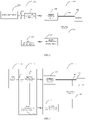
- a wireless charging system includes a power supply device 110, a wireless charging device 120, and a device to-be-charged 130.
- the wireless charging device 120 can be, for example, a wireless charging base.
- the device to-be-charged 130 can be, for example, a terminal.
- an output current of the power supply device 110 can be transmitted to the wireless charging device 120.
- the wireless charging device 120 can convert the output current of the power supply device 110 into an electromagnetic signal (or an electromagnetic wave) via an internal wireless transmitting circuit 121 for transmission.
- the wireless transmitting circuit 121 can convert the output current of the power supply device 110 into an alternating current (AC) and convert the AC into the electromagnetic signal via a transmitting coil or a transmitting antenna (not illustrated in FIG. 1 ).
- the device to-be-charged 130 can receive the electromagnetic signal from the wireless transmitting circuit 121 via a wireless receiving circuit 131 and convert the electromagnetic signal into an output current of the wireless receiving circuit 131.
- the wireless receiving circuit 131 can convert the electromagnetic signal transmitted by the wireless transmitting circuit 121 into an AC via a receiving coil or a receiving antenna (not illustrated in FIG. 1 ) and rectify and/or filter the AC to convert the AC into an output voltage and the output current of the wireless receiving circuit 131.
- the wireless charging device 120 and the device to-be-charged 130 will negotiate a transmission power of the wireless transmitting circuit 121.
- the output voltage and the output current of the wireless receiving circuit 131 are respectively 5V (volt) and 1A (ampere) in general.
- the power negotiated between the wireless charging device 120 and the device to-be-charged 130 is 10.8W for example, the output voltage and the output current of the wireless receiving circuit 131 are respectively 9V and 1.2A in general.
- the output voltage of the wireless receiving circuit 131 is however not suitable to be applied directly to a battery 133. Instead, the output voltage needs to be converted by a converting circuit 132 of the device to-be-charged 130 to obtain expected charging voltage and/or charging current of the battery 133 of the device to-be-charged 130.
- the converting circuit 132 can be configured to convert the output voltage of the wireless receiving circuit 131 to meet requirements on the expected charging voltage and/or charging current of the battery 133.
- the converting circuit 132 can be a charging management module, such as a charging integrated circuit (IC).
- the converting circuit 132 is configured to manage a charging voltage and/or a charging current of the battery 133.
- the converting circuit 132 can include at least one of a voltage feedback function and a current feedback function to achieve management of at least one of the charging voltage and the charging current of the battery 133 respectively.
- a charging process of the battery can include at least one of a trickle charging stage, a constant-current charging stage, and a constant-voltage charging stage.
- the converting circuit 132 can utilize the current feedback function to make current flowing into the battery 133 in the trickle charging stage satisfy the expected charging current of the battery 133 (such as a first charging current).
- the converting circuit 132 can utilize the current feedback function to make current flowing into the battery 133 in the constant-current charging stage satisfy the expected charging current of the battery 133 (such as a second charging current, which may be larger than the first charging current).
- the converting circuit 132 can utilize the voltage feedback function to make voltage applied to the battery 133 in the constant-voltage charging stage satisfy the expected charging voltage of the battery 133.
- the converting circuit 132 when the output voltage of the wireless receiving circuit 131 is higher than the expected charging voltage of the battery 133, the converting circuit 132 can be configured to decrease (that is, step down) the output voltage of the wireless receiving circuit 131 to make decreased charging voltage meet requirements on the expected charging voltage of the battery 133. As another example, when the output voltage of the wireless receiving circuit 131 is lower than the expected charging voltage of the battery 133, the converting circuit 132 can be configured to increase (that is, step up) the output voltage of the wireless receiving circuit 131 to make increased charging voltage meet requirements on the expected charging voltage of the battery 133.
- the output voltage of the wireless receiving circuit 131 is a constant 5V voltage, for example.
- the converting circuit 132 (such as a Buck circuit) can decrease the output voltage of the wireless receiving circuit 131 to make the decreased charging voltage meet requirements on the expected charging voltage of the battery 133.
- the output voltage of the wireless receiving circuit 131 is a constant 5V voltage, for example.
- the converting circuit 132 (such as a Boost circuit) can increase the output voltage of the wireless receiving circuit 131 to make the increased charging voltage meet requirements on the expected charging voltage of the battery 133.
- the converting circuit 132 is limited by low circuit conversion efficiency, which causes electrical energy that fails to be converted to dissipate in the form of heat.
- the heat can be accumulated inside the device to-be-charged 130. Since designed space and heat dissipation space of the device to-be-charged 130 are both very small, for example, the physical size of a user's mobile terminal is increasingly lighter and thinner, and a large number of electronic components are densely arranged in the mobile terminal at the same time, difficulty in designing the converting circuit 132 is increased. In addition, it is difficult to remove promptly heat accumulated inside the device to-be-charged 130, which in turn results in abnormality of the device to-be-charged 130.
- heat accumulated in the converting circuit 132 may cause heat interference with electronic components near the converting circuit 132, which results in working abnormality of the electronic components.
- the heat accumulated in the converting circuit 132 may shorten service life of the converting circuit 132 and the electronic components near the converting circuit 132.
- the heat accumulated in the converting circuit 132 may cause heat interference with the battery 133, which in turn brings about abnormality of charge and discharge of the battery 133.
- the heat accumulated in the converting circuit 132 may raise temperature of the device to-be-charged 130 and thus influence user experience in the charging process.
- the heat accumulated in the converting circuit 132 may result in short circuit of the converting circuit 132 itself, and as a result, the output voltage of the wireless receiving circuit 131 is directly applied to the battery 133 and causes abnormality of charging. In case that the battery 133 is charged with overvoltage for a long time, explosion of the battery 133 may even occur, thus putting users at risk.
- a wireless charging system in implementations of the disclosure.
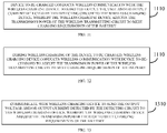
- a wireless charging device and a device to-be-charged can conduct wireless communication.
- a transmission power of the wireless charging device can be adjusted according to feedback information of the device to-be-charged, to make the transmission power of a wireless receiving circuit of the device to-be-charged match a present charging stage of the battery.
- the wireless charging device and the device to-be-charged can communicate with each other, and the transmission power of the wireless charging device can be adjusted according to feedback information received from the device to-be-charged, such that the output voltage and/or output current of the wireless receiving circuit of the device to-be-charged can meet present charging requirements of the battery, such as present requirements on charging current and/or charging voltage, in the device to-be-charged, the output voltage and/or output current of the wireless receiving circuit can be applied directly to the battery for charging (referred to as "direct charging” hereinafter), which can avoid problems such as energy loss, heating, etc. due to conversion on the output voltage and/or output current of the wireless receiving circuit conducted by the converting circuit described above.
- direct charging directly charging
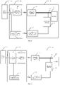
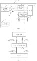
- the wireless charging system 200 in implementations of the disclosure includes a wireless charging device 220 and a device to-be-charged 230.
- the wireless charging device 220 is configured to charge the device to-be-charged 230.
- the wireless charging device 220 includes a wireless transmitting circuit 221 and a first communication control circuit 222.
- Control function of the first communication control circuit 222 can be achieved by, for instance, a micro control unit (MCU).
- MCU micro control unit
- the wireless transmitting circuit 221 is configured to transmit an electromagnetic signal.
- the wireless transmitting circuit 221 can include a wireless transmission driving circuit and a transmitting coil or a transmitting antenna (not illustrated in FIG. 2 ).
- the wireless transmission driving circuit is configured to generate an AC of high frequency.
- the transmitting coil or the transmitting antenna can be configured to convert the AC of high frequency into the electromagnetic signal for transmission.
- the first communication control circuit 222 is configured to conduct wireless communication with the device to-be-charged 230 in a process that the wireless charging device 220 charges device to-be-charged 230 wirelessly. Specifically, the first communication control circuit 222 is configured to communicate with a second communication control circuit 235 of the device to-be-charged 230.
- the manner of communication between the first communication control circuit 222 and the second communication control circuit 235 and information exchanged between the first communication control circuit 222 and the second communication control circuit 235 are not limited herein, which will be described in detail hereinafter in conjunction with specific implementations.
- the device to-be-charged 230 includes a wireless receiving circuit 231, a battery 232, a detecting circuit 234, and the second communication control circuit 235.
- Control function of the second communication control circuit 235 can be achieved by, for instance, an MCU, or be cooperatively achieved by the MCU and an application processor (AP) of the device to-be-charged.
- AP application processor
- the wireless receiving circuit 231 is configured to receive the electromagnetic signal and convert the electromagnetic signal to provide an output voltage and an output current to the battery 232.
- the wireless receiving circuit 231 includes a receiving coil or a receiving antenna (not illustrated in FIG. 2 ) and a shaping circuit (such as a rectifying circuit and/or a filtering circuit) coupled with the receiving coil and the receiving antenna.
- the receiving antenna or the receiving coil is configured to convert the electromagnetic signal into an AC.
- the shaping circuit is configured to convert the AC into the output voltage and the output current of the wireless receiving circuit 231.
- the form of the shaping circuit and the form of the output voltage and the output current of the wireless receiving circuit 231 obtained after processing of the shaping circuit are not limited herein.
- the shaping circuit can include the rectifying circuit and the filtering circuit.
- the output voltage of the wireless receiving circuit 231 can be a steady voltage obtained after filtering.
- the shaping circuit can include the rectifying circuit.
- the output voltage of the wireless receiving circuit 231 can be a pulsating waveform voltage obtained after rectification. The pulsating waveform voltage is applied directly to the battery 232 of the device to-be-charged 230 to charge the battery 232.
- the output current of the wireless receiving circuit 231 is used for charging the battery 232 in an intermittent manner.
- Period of the output current of the wireless receiving circuit 231 can vary with frequency of an AC input (such as an AC power grid) into the wireless charging system 200.
- frequency corresponding to the period of the output current of the wireless receiving circuit 231 is N or 1/N times (N is a positive integer) of frequency of a power grid.
- current waveform corresponding to the output current of the wireless receiving circuit 231 can include one pulse or one group of pulses synchronized with the power grid.
- the magnitude of such pulsating voltage or pulsating current changes periodically, which can reduce lithium precipitation of a lithium battery and prolong service life of a battery.
- the pulsating voltage or pulsating current is beneficial to reducing polarization effect of the battery, increasing charging speed, and reducing heating of the battery, thereby ensuring safety and reliability in charging of the device to-be-charged.
- the detecting circuit 234 is configured to detect an output voltage and/or an output current of the wireless receiving circuit 231.
- the detecting circuit 234 can include a voltage detecting circuit and a voltage detecting circuit.
- the voltage detecting circuit is configured to sample the output voltage of the wireless receiving circuit 231 and transmit sampled voltage value to the second communication control circuit 235. In some examples, the voltage detecting circuit is configured to sample the output voltage of the wireless receiving circuit 231 in a series-voltage division manner.
- the current detecting circuit is configured to sample the output current of the wireless receiving circuit 231 and transmit sampled current value to the second communication control circuit 235.
- the current detecting circuit is configured to sample the output current of the wireless receiving circuit 231 via a current sensing resistor and a current detector.
- the second communication control circuit 235 is configured to conduct wireless communication with the first communication control circuit 222, to transmit to the first communication control circuit 222 the output voltage and/or the output current of the wireless receiving circuit 231 detected by the detecting circuit 234, whereby the first communication control circuit 222 adjusts a transmission power of the wireless transmitting circuit 221 to meet charging requirements of the battery 232.
- the second communication control circuit 235 is configured to conduct wireless communication with the first communication control circuit 222 according to the output voltage and/or the output current of the wireless receiving circuit 231 detected by the detecting circuit 234, whereby the first communication control circuit 222 adjusts the transmission power of the wireless transmitting circuit 221 to make the output voltage and/or the output current of the wireless receiving circuit 231 meet requirements on charging of the battery 232.
- the charging requirements include requirements on charging current and/or requirements on charging voltage of the battery 232.
- the second communication control circuit 235 is configured to conduct wireless communication with the first communication control circuit 222, to transmit to the first communication control circuit 222 the output voltage and/or the output current of the wireless receiving circuit 231 detected by the detecting circuit 234, whereby the first communication control circuit 222 adjusts the transmission power of the wireless transmitting circuit 231, to make the output voltage and/or output current of the wireless receiving circuit 231 match a present charging stage of the battery 232.
- the second communication control circuit 235 is configured to conduct wireless communication with the first communication control circuit 222 according to the output voltage and/or the output current of the wireless receiving circuit 231 detected by the detecting circuit 234, whereby the first communication control circuit 222 adjusts the transmission power of the wireless transmitting circuit 221 to make the output voltage and/or the output current of the wireless receiving circuit 231 meet requirements on charging of the battery 232 in at least one of a trickle charging stage, a constant-voltage charging stage, and a constant-current charging stage.
- the second communication control circuit 235 can be configured to conduct wireless communication with the first communication control circuit 222 according to the output voltage and/or output current of the wireless receiving circuit 231 detected by the detecting circuit 234, whereby the first communication control circuit 222 can conduct constant-voltage and/or constant current control on the charging process of the battery 232 by adjusting the transmission power of the wireless transmitting circuit 221.
- the charging process of the battery can include at least one of the trickle charging stage, the constant-voltage charging stage, and the constant-current charging stage.
- the second communication control circuit 235 is configured to: in the trickle charging stage of the battery 232, conduct wireless communication with the first communication control circuit 222 according to the output voltage and/or the output current of the wireless receiving circuit 231 detected by the detecting circuit 234, whereby the first communication control circuit 222 adjusts the transmission power of the wireless transmitting circuit 221 to make the output current of the wireless receiving circuit 231 match a charging current corresponding to the trickle charging stage (or to make the output current of the wireless receiving circuit 231 meet requirements on charging current of the battery 232 in the trickle charging stage).
- the charging current corresponding to the trickle charging stage is 1A.
- the output current of the wireless receiving circuit 231 can be detected in real time by the detecting circuit 234.
- the second communication control circuit 235 can communicate with the first communication control circuit 222, whereby the first communication control circuit 222 adjusts the transmission power of the wireless transmitting circuit 221 to make the output current of the wireless receiving circuit 231 returns to 1A.
- the second communication control circuit 235 is configured to: in the constant-voltage charging stage of the battery 232, conduct wireless communication with the first communication control circuit 222 according to the output voltage and/or the output current of the wireless receiving circuit 231 detected by the detecting circuit 234, whereby the first communication control circuit 222 adjusts the transmission power of the wireless transmitting circuit 221 to make the output voltage of the wireless receiving circuit 231 match a charging voltage corresponding to the constant-voltage charging stage (or to make the output voltage of the wireless receiving circuit 231 meet requirements on charging voltage of the battery 232 in the constant-voltage charging stage).
- the charging voltage corresponding to the constant-voltage charging stage is 5V.
- the output voltage of the wireless receiving circuit 231 can be detected in real time by the detecting circuit 234.
- the second communication control circuit 235 can communicate with the first communication control circuit 222, whereby the first communication control circuit 222 adjusts the transmission power of the wireless transmitting circuit 221 to make the output voltage of the wireless receiving circuit 231 returns to 5V.
- the output voltage of the wireless receiving circuit 231 which is not limited herein. For instance, transmission of an electromagnetic signal between the wireless transmitting circuit 221 and the wireless receiving circuit 231 is interfered, which results in lower efficiency in energy conversion and thus makes the output voltage of the wireless receiving circuit 231 lower than 5V.
- the second communication control circuit 235 is configured to: in the constant-current charging stage of the battery 232, conduct wireless communication with the first communication control circuit 222 according to the output voltage and/or the output current of the wireless receiving circuit 231 detected by the detecting circuit 234, whereby the first communication control circuit 222 adjusts the transmission power of the wireless transmitting circuit 221 to make the output current of the wireless receiving circuit 231 match a charging current corresponding to the constant-current charging stage (or to make the output current of the wireless receiving circuit 231 meet requirements on charging current of the battery 232 in the constant-current charging stage).
- the charging current corresponding to the constant-current charging stage is 2A.
- the output current of the wireless receiving circuit 231 can be detected in real time by the detecting circuit.
- the second communication control circuit 235 can communicate with the first communication control circuit 222, whereby the first communication control circuit 222 adjusts the transmission power of the wireless transmitting circuit 221 to make the output current of the wireless receiving circuit 231 returns to 2A.
- the output current of the wireless receiving circuit 231 which is not limited herein. For instance, transmission of an electromagnetic signal between the wireless transmitting circuit 221 and the wireless receiving circuit 231 is interfered, which results in lower efficiency in energy conversion and thus makes the output current of the wireless receiving circuit 231 smaller than 2A.
- the constant-current charging stage or the constant-current stage referred to herein does not require that the charging current remain completely constant, and may be, for example, a peak value (that is, peak current) or an average value of the charging current remaining constant within a certain time period.
- a peak value that is, peak current
- an average value of the charging current remaining constant within a certain time period e.g., a multi-stage constant current charging manner is usually adopted for charging.
- a first stage of charging begins with a pre-determined charging current.
- the N constant-current stages of the multi-stage constant current charging are executed in sequence from the first stage to the Nth stage.
- the peak value or average value of a pulsating waveform current may decrease.
- the multi-stage constant current charging proceeds to a subsequent constant-current stage, that is, the previous constant-current stage ends and the next constant-current stage begins. Current conversion between two adjacent constant-current stages may be gradual or in a step-like manner.
- the device to-be-charged can be a terminal.
- the "terminal" can include but is not limited to a device coupled via a wired line and/or a wireless interface to receive/transmit communication signals.
- Examples of the wired line may include, but are not limited to, at least one of a public switched telephone network (PSTN), a digital subscriber line (DSL), a digital cable, a direct connection cable, and/or other data connection lines or network connection lines.
- Examples of the wireless interface may include, but are not limited to, a wireless interface with a cellular network, a wireless local area network (WLAN), a digital television network (such as a digital video broadcasting-handheld (DVB-H) network), a satellite network, an amplitude modulation-frequency modulation (AM-FM) broadcast transmitter, and/or with other communication terminals.
- a communication terminal configured to communicate via a wireless interface may be called a "wireless communication terminal", a “wireless terminal”, and/or a "mobile terminal”.
- Examples of a mobile terminal may include, but are not limited to, a satellite or cellular telephone, a personal communication system (PCS) terminal capable of cellular radio telephone, data processing, fax, and/or data communication, a personal digital assistant (PDA) equipped with radio telephone, pager, Internet/Intranet access, web browsing, notebook, calendar, and/or global positioning system (GPS) receiver, and a conventional laptop or a handheld receiver or other electronic devices equipped with radio telephone transceiver.
- the device to-be-charged or terminal can also include a power bank.
- the power bank can be configured to be charged by an adaptor and thus store energy to charge other electronic devices.
- the manner and order of communication between the wireless charging device 220 and the device to-be-charged 230 are not limited herein.
- the wireless communication between the wireless charging device 220 and the device to-be-charged 230 is a one-way wireless communication.
- the device to-be-charged 230 is an initiator of communication and the wireless charging device 220 is a receiver of communication.
- the device to-be-charged 230 can detect in real time the charging current of the battery 232 (that is, the output current of the wireless receiving circuit 231) through the detecting circuit 234.
- the device to-be-charged 230 can send adjustment information to the wireless charging device 220 to instruct the wireless charging device 220 to adjust the transmission power of the wireless transmitting circuit 221.
- the wireless communication between the wireless charging device 220 and the device to-be-charged 230 is a two-way wireless communication.
- the two-way wireless communication generally requires that the receiver send response information to the initiator after receiving communication request initiated by the initiator. Two-way communication mechanism can make communication safer.
- any one of the wireless charging device 220 and the device to-be-charged 230 can function as a master device to initiate a two-way communication, and correspondingly the other one of the wireless charging device 220 and the device to-be-charged 230 can function as a slave device to make a first response or a first reply to the communication initiated by the master device.
- the master device and the slave device can be determined by comparing link states between the wireless charging device 220 and the device to-be-charged 230. For example, suppose a wireless link in which the wireless charging device 220 sends information to the device to-be-charged 230 is an uplink and a wireless link in which the device to-be-charged 230 sends information to the wireless charging device 220 is a downlink. When the uplink is of higher quality, the wireless charging device 220 can be determined as the master device of communication. When the downlink is of higher quality, the device to-be-charged 230 can be determined as the master device of communication.
- any one of the wireless charging device 220 and the device to-be-charged 230 can function as the master device to initiate the two-way communication, and correspondingly the other one of the wireless charging device 220 and the device to-be-charged 230 can function as the slave device to make the first response or the first reply to the communication initiated by the master device.
- the master device can make a second response to the first response or the first reply of the slave device, and as such, the master device and the slave device complete one communication negotiation.
- the master device can make the second response to the first response or the first reply of the slave device as follows.
- the master device receives from the slave device the first response or the first reply to the communication and makes the second response to the first response or the first reply of the slave device.
- the master device can also make the second response to the first response or the first reply of the slave device as follows.
- the master device fails to receive from the slave device the first response or the first reply to the communication within a preset time period, the master device can still make the second response to the first response or the first reply made by the slave device.
- the wireless charging device 220 after the device to-be-charged 230, as the master device, initiates the communication and the wireless charging device 220, as the slave device, makes the first response or the first reply to the communication initiated by the master device, it can be considered that the wireless charging device 220 and the device to-be-charged 230 have complete a communication negotiation without requiring the device to-be-charged 230 to make the second response to the first response or the first reply of the wireless charging device 220.
- the mode of wireless communication between the first communication control circuit 222 of the wireless charging device 220 and the second communication control circuit 235 of the device to-be-charged 230 is not limited herein.
- the first communication control circuit is configured to conduct wireless communication with the second communication control circuit based on Bluetooth, wireless fidelity (Wi-Fi), short-range wireless communication based on high carrier frequency, optical communication, ultrasonic communication, ultra-wideband communication, and mobile communication.
- the first communication control circuit 222 includes at least one of the following modules for wireless communication with the second communication control circuit 235: a Bluetooth module, a Wi-Fi module, a high carrier frequency based short-range wireless communication module, an optical communication module, an ultrasonic communication module, an ultra-wideband communication module, and a mobile communication module.
- the high carrier frequency based short-range wireless communication module includes an IC chip module with an EHF antenna inside.
- the high carrier frequency is 60 GHz.
- the optical communication module includes an infrared communication module, which can use infrared to transmit information.
- the mobile communication module can transmit information based on mobile communication protocols such as 5G communication protocol, 4G communication protocol, or 3G communication protocol.
- mobile communication protocols such as 5G communication protocol, 4G communication protocol, or 3G communication protocol.
- the second communication control module 235 includes at least one of the following modules for wireless communication with the first communication control circuit 222: a Bluetooth module, a Wi-Fi module, a high carrier frequency based short-range wireless communication module, an optical communication module, an ultrasonic communication module, an ultra-wideband communication module, and a mobile communication module.
- wireless communication between the first communication control circuit 222 and the second communication control module 235 can be conducted based on at least one of: Bluetooth communication, Wi-Fi communication, short-range wireless communication based on high carrier frequency, optical communication, ultrasonic communication, ultra-wideband communication, and mobile communication.
- wireless communication includes standard communication and non-standard communication.
- standard wireless communication includes, for example: link protocol, such as Bluetooth, IEEE 802.11 (wireless LANs), 802.15 (WPANs), 802.16 (WiMAX), 802.20 mobile wireless wideband access; cellular protocol (mobile communication protocol), such as 5G standard protocol, LTE, CDMA, GSM; Zigbee and ultra wideband (UWB) technology.
- link protocol such as Bluetooth, IEEE 802.11 (wireless LANs), 802.15 (WPANs), 802.16 (WiMAX), 802.20 mobile wireless wideband access
- cellular protocol mobile communication protocol
- mobile communication protocol such as 5G standard protocol, LTE, CDMA, GSM
- These protocols support radio frequency communication, and some support infrared communication.
- Other wireless communication forms such as ultrasound communication, optical communication, short-range wireless communication based on high carrier frequency can also be adopted. It should be understood that the above wireless communication standard include past
- the first communication control circuit 222 and the second communication control module 235 can also determine the wireless communication mode to be adopted according to signal strength of various wireless communication modes detected. For example, when Wi-Fi is used for wireless communication, if it is detected that the Wi-Fi signal is weak, then switch to use other wireless communication mode.
- the wireless charging device 220 can adjust the transmission power in real time according to the information received.
- reliability of communication and safety of charging can be improved.
- the related art such as Qi standard
- reliability of communication can be improved, and voltage ripple, which is caused by signal coupling based communication and affects the voltage process of a converting circuit or a Step-down circuit of the device to-be-charged, can be avoided.
- the second communication control circuit 235 can be configured to conduct the wireless communication with the first communication control circuit 222 according to the output voltage and/or the output current of the wireless receiving circuit 231 detected by the detecting circuit 234, whereby the first communication control circuit 222 adjusts the transmission power of the wireless transmitting circuit 221.
- contents communicated between the first communication control circuit 222 and the second communication control circuit 235 is not limited herein.
- the second communication control circuit 235 is configured to send to the first communication control circuit 222 the output voltage and/or the output current of the wireless receiving circuit 231 detected by the detecting circuit 234.
- the second communication control circuit 235 can be further configured to send battery-state information to the first communication control circuit 222.
- the battery-state information includes a present power and/or a present voltage of the battery 232 of the device to-be-charged 230.
- the first communication control circuit 222 can determine the present charging stage of the battery 232 according to the battery-state information, to further determine a target charging voltage and/or a target charging current that matches the present charging stage of the battery 232.
- the first communication control circuit 222 can compare the output voltage and/or the output current of the wireless receiving circuit 231 received from the second communication control circuit 235 with the above target charging voltage and/or target charging current to determine whether the output voltage and/or the output current of the wireless receiving circuit 231 matches the present charging stage of the battery 232.
- the first communication control circuit 222 can adjust the transmission power of the wireless transmitting circuit 221 until the output voltage and/or the output current of the wireless receiving circuit 231 matches the present charging stage of the battery 232.
- the second communication control circuit 235 is configured to send adjustment information to the first communication control circuit 222 to instruct the first communication control circuit 222 to adjust the transmission power of the wireless transmitting circuit 221.
- the second communication control circuit 235 can instruct the first communication control circuit 222 to increase the transmission power of the wireless transmitting circuit 221.
- the second communication control circuit 235 can instruct the first communication control circuit 222 to reduce the transmission power of the wireless transmitting circuit 221.
- the wireless charging device 220 can set the transmission power of the wireless transmitting circuit 221 to have multiple grades.
- the first communication control circuit 222 adjusts the transmission power of the wireless transmitting circuit 221 by one grade until the output voltage and/or the output current of the wireless receiving circuit 231 matches the present charging stage of the battery 232.
- the first communication control circuit 222 and the second communication control circuit 235 can also be configured to exchange other types of information communicated.
- the first communication control circuit 222 and the second communication control circuit 235 can exchange information for safety protection, abnormality detection, or fault handling, such as temperature information of the battery 232, information indicative of over-voltage protection or over-current protection, etc., or power-transmission efficiency information (for indicating efficiency in power delivery between the wireless transmitting circuit 221 and the wireless receiving circuit 231).
- the first communication control circuit 222 and/or the second communication control circuit 235 can control a charging loop to a protection state, such as controlling the charging loop to stop the wireless charging.
- the first communication control circuit 222 can reduce the transmission power, or control the wireless transmitting circuit 221 to stop working.
- the first communication control circuit 222 can control the wireless transmitting circuit 221 to stop working if power-transmission efficiency is lower than a preset threshold and notify user of the event.
- the fact that the power-transmission efficiency is excessively low can be displayed via a display screen, or be indicated by an indicator lamp in order for the user to adjust wireless charging environment.
- the first communication control circuit 222 and the second communication control circuit 235 can be configured to exchange other types of information for adjusting the transmission power of the wireless transmitting circuit 221, such as the temperature information of the battery 232, information indicative of a peak value or an average value of the output voltage and/or output current of the wireless receiving circuit 231, information indicative a peak value or an average value of the current in the first charging channel 233, the power-transmission efficiency information (indicative of efficiency in power delivery between the wireless transmitting circuit 221 and the wireless receiving circuit 231), etc.
- the second communication control circuit 235 can send the power-transmission efficiency information to the first communication control circuit 222.
- the first communication control circuit 222 can be further configured to determine an adjustment range of the transmission power of the wireless transmitting circuit 221 according to the power-transmission efficiency information. Specifically, when the power-transmission efficiency information indicates that the efficiency in power delivery between the wireless transmitting circuit 221 and the wireless receiving circuit 231 is low, the first communication control circuit 222 can increase the adjustment range of the transmission power of the wireless transmitting circuit 221 to make the transmission power of the wireless transmitting circuit 221 reach promptly a target power.
- the second communication control circuit 235 can send at least one of the information indicative of a peak value or an average value of the output voltage of the wireless receiving circuit 231 and the information indicative of a peak value or an average value of the output current of the first charging channel 233 to the first communication control circuit 222.
- the first communication control circuit 222 can determine whether the peak value or the average value of the output voltage and/or the output current of the wireless receiving circuit 231 matches the present charging stage of the battery. When the peak value or the average value of the output voltage and/or the output current of the wireless receiving circuit 231 does not match the present charging stage of the battery, the first communication control circuit 222 will adjust the transmission power of the wireless transmitting circuit 221.
- the second communication control circuit 235 can send the temperature information of the battery 232 to the first communication control circuit 222.
- the first communication control circuit 222 will reduce the transmission power of the wireless transmitting circuit 221 to decrease the output current of the wireless receiving circuit 231, thereby reducing the temperature of the battery 232.
- Contents communicated between the second communication control circuit 235 and the first communication control circuit 222 can be contents of file transfer.
- the wireless charging device and the device to-be-charged can communicate with each other as mentioned above, in this way, there is no need to use a transmitting coil and a receiving coil, which are used for charging, to participate in communication, thus the problem of ripples in output voltage caused by coil communication can be solved.
- the voltage ripples occurred when the wireless receiving coil outputs, if the voltage ripples are not handled effectively, it may lead to wireless charging security problems and security risks.
- voltage ripples can be eliminated, and accordingly, circuits for handling voltage ripples can be omitted, as such, the complexity of the charging circuit of the device to-be-charged can be reduced, the charging efficiency can be improved, the setting space of the circuit can be saved, and the cost can be reduced.
- the battery can be charged through the first charging channel, where the first charging channel is provided with a Step-down circuit. Since the device to-be-charged feeds back to the wireless charging device information on the voltage, current, or power entering the battery, the wireless charging device can adjust the transmission power in real time. Since voltage ripples are eliminated and the Step-down circuit can be implemented with a half-voltage circuit, complexity of the circuit can be further reduced, which is be beneficial to temperature control and charging efficiency improvement.
- the wireless charging device 220 may further includes a charging interface 233.
- the wireless transmitting circuit 221 is further configured to receive the output voltage and the output current of the power supply device 210 through the charging interface 233, and generate the electromagnetic signal according to the output voltage and output current of the power supply device 210.
- the type of the power supply device 210 is not limited herein.
- the power supply device 210 can be a power adapter, a power bank, or a computer.
- the type of the charging interface 223 is not specifically limited herein.
- the charging interface 223 is a USB interface.
- the USB interface can be, for example, a USB 2.0 interface, a micro USB interface, or a USB TYPE-C interface.
- the charging interface 223 can also be a lightning interface, or other types of parallel interface and/or serial interface that is used for charging.
- the manner of communication between the first communication control circuit 222 and the power supply device 210 is no limited herein.
- the first communication control circuit 222 can be coupled with and communicate with the power supply device 210 via another communication interface other than the charging interface.
- the first communication control circuit 222 can communicate with the power supply device 210 in a wireless manner.
- the first communication control circuit 222 can conduct near field communication (NFC) with the power supply device 210.
- NFC near field communication
- the first communication control circuit 222 can communicate with the power supply device 210 via the charging interface 223 without providing any extra communication interface or another wireless communication module, which can simplify the implementation of the wireless charging device 220.
- the charging interface 223 is a USB interface.
- the first communication control circuit 222 can communicate with the power supply device 210 via a data line (such as a D+ line and/or a D- line) of the USB interface.
- the charging interface 223 is a USB interface supporting a power delivery (PD) communication protocol (such as the USB TYPE-C interface).
- the first communication control circuit 222 can communicate with the power supply device 210 based on the PD communication protocol.
- the power supply device 210 can be a normal power supply device with a fixed output power, or can be the power supply device with an adjustable output power provided herein. In the following, the power supply device 210 will be described below first as a power supply device with an adjustable output power and then as a power supply device with a fixed output power.
- the power supply device with an adjustable output power may be provided with a voltage feedback loop and a current feedback loop and therefore, can adjust its output voltage and/or output current according to actual needs.
- the power supply device 210 may be further equipped with a communication function.
- the first communication control circuit 222 is further configured to communicate with the power supply device 210 to negotiate the output power of the power supply device 210.
- the wireless charging device 220 can adjust continuously the transmission power of the wireless transmitting circuit 221 to make the output voltage and/or the output current of the wireless receiving circuit 231 matches the present charging stage of the battery 232.
- the manner in which the transmission power of the wireless transmitting circuit 221 is adjusted is not limited herein.
- the first communication control circuit 222 can communicate with a power supply device 210 for adjustment of an output voltage and/or an output current of the power supply device 210, so as to adjust the transmission power of the wireless transmitting circuit 221.
- the first communication control circuit 222 is configured to adjust an amount of power extracted by the wireless transmitting circuit 221 from a maximum output power provided by the power supply device 210 to adjust the transmission power of the wireless transmitting circuit 221.
- the manner in which the transmission power of the wireless transmitting circuit 221 is adjusted will be elaborated with reference to FIG. 4 and FIG. 5 .
- the first communication control circuit 221 can communicate with the power supply device 210 to negotiate the maximum output power of the power supply device 210.
- the first communication control circuit 221 can adjust an amount of power extracted by the wireless transmitting circuit 221 from a maximum output power, to adjust the transmission power of the wireless transmitting circuit 221.
- the first communication control circuit 222 communicates with the power supply device 210 with adjustable output power to negotiate the maximum output power of the power supply device 210. After negotiation is completed, the power supply device 210 provides an output voltage and an output current to the wireless charging device 220 according to the maximum output power. During charging, the first communication control circuit 222 extracts a certain amount of power from the maximum output power for wireless charging according to actual needs. In other words, in implementations of the disclosure, control on adjustment of the transmission power of the wireless transmitting circuit 221 is allotted to the first communication control circuit 222. As such, the first communication control circuit 222 can adjust the transmission power of the wireless transmitting circuit 221 immediately after receiving feedback information from the device to-be-charged 230, which has advantages of high adjusting speed and high efficiency.
- the manner in which the first communication control circuit 222 adjusts the transmission power of the wireless transmitting circuit 221 is not limited herein.
- a power adjusting circuit can be disposed inside the first communication control circuit 222, inside the wireless transmitting circuit 221, or between the first communication control circuit 222 and the wireless transmitting circuit 221.
- the power adjusting circuit can be coupled with the transmitting coil or the transmitting antenna to adjust power received by the transmitting coil or the transmitting antenna.
- the power adjusting circuit can include, for example, a pulse width modulation (PWM) controller and a switch component.
- the first communication control circuit 222 can adjust the transmission power of the wireless transmitting circuit 221 by adjusting a duty cycle of a control signal transmitted by the PWM controller and/or by controlling switch frequency of the switch component.
- PWM pulse width modulation
- the power supply device 210 can also output a constant and high output power (such as 40W) directly.
- the first communication control circuit 222 can adjust directly the amount of power extracted by the wireless transmitting circuit 221 from such constant output power of the power supply device 210 without negotiating with the power supply device 210 the maximum output power of the power supply device 210.
- the first communication control circuit 221 can communicate with the power supply device 210 to adjust the output voltage and/or output current of the power supply device 210, so as to adjust the transmission power of the wireless transmitting circuit 221.
- the first communication control circuit 222 can be coupled with the wireless transmitting circuit 221 to control the wireless transmitting circuit 221 to work, or control the wireless transmitting circuit 221 to stop working when the wireless charging is abnormal. Alternatively, the first communication control circuit 222 may not be coupled with the wireless transmitting circuit 221.
- control on adjustment of the transmission power of the wireless transmitting circuit 221 is allotted to the power supply device 210, and the power supply device 210 is configured to adjust the transmission power of the wireless transmitting circuit 221 by changing the output voltage and/or output current.
- the power supply device 210 can provide the exact amount of power required by the wireless charging device 220, and there is no waste of power.
- the wireless charging device 220 can determine actively whether it is necessary to adjust the output voltage and/or the output current of the power supply device 210.
- the wireless charging device 220 can function as a "bridge" of communication between the power supply device 210 and the device to-be-charged 230 and forward information between the power supply device 210 and the device to-be-charged 230.
- the first communication control circuit 222 communicates with the device to-be-charged 230 during wireless charging to determine whether it is necessary to adjust the output voltage and/or the output current of the power supply device 210.
- the first communication control circuit 222 communicates with the power supply device 210 to instruct the power supply device 210 to adjust the output voltage and/or the output current of the power supply device 210.
- the first communication control circuit 222 of the wireless charging device 220 conducts wireless communication with the device to-be-charged 230 during wireless charging to acquire adjustment information.
- the adjustment information is for instructing adjustment of the output voltage and/or the output current of the power supply device 210.
- the first communication control circuit 222 communicates with the power supply device 210 to send the adjustment information to the power supply device 210, whereby the power supply device 210 adjusts the output voltage and/or the output current of the power supply device according to the adjustment information.
- the communication between the wireless charging device 220 (or the first communication control circuit 222) and the power supply device 210 can be a one-way communication or a two-way communication and is not limited herein.
- the wireless charging device 220 may further includes a first converting circuit 234.
- the first converting circuit 234 is configured to receive and convert the output voltage and the output current of the power supply device 210.
- the wireless transmitting circuit 221 is further configured to generate the electromagnetic signal according to the output voltage and the output current subjected to conversion (that is, a converted voltage and a converted current).
- the first communication control circuit 222 is configured to: adjust the voltage and/or current subjected to conversion of the first converting circuit 224 to adjust the transmission power of the wireless transmitting circuit 221.
- the wireless charging device 220 provided herein can continuously adjust the transmission power of the wireless transmitting circuit 221 during charging, to make the output voltage and/or output current of the wireless receiving circuit 231 match a present charging stage of the battery 232.
- the manner in which the transmission power of the wireless transmitting circuit 221 is adjusted is not limited herein.
- the power supply device 210 provided herein is a normal power supply device 210 with a fixed output power
- the first communication control circuit 222 can adjust the output voltage and/or output current of the first converting circuit 224 to adjust the transmission power of the wireless transmitting circuit 221, this improves the versatility of the wireless charging device 220 to be applied to the existing common power supply device 210.
- the first converting circuit 224 can include for example a pulse width modulation (PWM) controller and a switch component.
- the first communication control circuit 222 can adjust the transmission power of the wireless transmitting circuit 221 by adjusting a duty cycle of a control signal transmitted by the PWM controller and/or by adjusting the output voltage and/or output current of the first converting circuit through controlling switch frequency of the switch component.
- PWM pulse width modulation
- the first converting circuit 224 can receive the output voltage and output current from the power supply device 210 through the charging interface 233.
- the wireless charging device 220 provided herein can be coupled with a normal power supply device through the charging interface 233.
- the first communication control circuit 222 can control the first converting circuit 224 to work, and adjust the output voltage and/or output current of the first converting circuit 224 according to feedback information of the device to-be-charged 230, whereby the transmission power of the wireless transmitting circuit 222 meets charging requirements of the battery 232.
- Such adjustment manner is similar to the alternative manner illustrated in FIG.4 and here, control on adjustment of the transmission power of the wireless transmitting circuit 221 is also allotted to the first communication control circuit 222, and the first communication control circuit 222 is configured to adjust the transmission power of the wireless transmitting circuit 221 upon receiving the feedback information of the device to-be-charged 230.
- Such adjustment has advantages of fast adjustment speed and high efficiency, for example.
- the output current of the power supply device 210 can be a constant DC, a pulsating DC, or an AC and is not limited herein.
- the wireless charging device 220 can also be integrated with functions similar to an adapter, thus, it is possible for the wireless charging device 220 to convert directly an external input AC (e.g. mains supply) into the above electromagnetic signal.
- a function similar to an adapter can be integrated into a wireless transmitting circuit 221 of a wireless charging device 220, for example, the wireless transmitting circuit 221 can be integrated with a rectifier circuit, a primary filter circuit and/or a transformer. In this way, the wireless transmitting circuit 221 can be used to receive external input AC (such as 220V AC, also known as mains supply or commercial electricity), according to which electromagnetic signals can be generated.
- a function similar to an adaptor is integrated into the wireless charging device 220, which makes it unnecessary for the wireless charging device 220 to acquire power from an external power supply device, thus improves the integration of the wireless charging device 220, and decreases the number of components required for wireless charging.
- the wireless charging device 220 is operable in a first wireless charging mode or in a second wireless charging mode, and a charging speed at which the wireless charging device 220 charges the device to-be-charged 230 in the first wireless charging mode is higher than in the second wireless charging mode. In other words, compared with the wireless charging device 220 working in the second wireless charging mode, the wireless charging device 220 working in the first wireless charging mode takes less time to fully charge a battery of the same capacity of the device to-be-charged 230.
- the second wireless charging mode can be referred to as a normal wireless charging mode and can be, for example, a conventional wireless charging mode based on the QI standard, the PMA standard, or the A4WP standard.
- the first wireless charging mode can be referred to as a quick wireless charging mode.
- the normal wireless charging mode can refer to a wireless charging mode in which the wireless charging device 220 has a low transmission power (usually lower than 15W, and the commonly used transmission power is 5W or 10W). In the normal wireless charging mode, it usually takes several hours to fully charge a battery of high capacity (such as 3000mA). However, in the quick wireless charging mode, the transmission power of the wireless charging device 220 is relatively high (usually higher than or equal to 15W). Compared with the normal wireless charging mode, in the quick wireless charging mode, the wireless charging device 220 can fully charge a battery of the same capacity within a substantially shorter charging period, and the charging is faster.
- the first communication control circuit 222 conducts a two-way communication with the second communication control circuit 235 to control a transmission power of the wireless charging device 220 in the first wireless charging mode.
- the first communication control circuit 222 conducts the two-way communication with the second communication control circuit 235 to control the transmission power of the wireless charging device 220 in the first wireless charging mode as follows.
- the first communication control circuit 222 conducts the two-way communication with the second communication control circuit 235 to negotiate which wireless charging mode to be used between the wireless charging device 220 and the device to-be-charged 230.
- the first communication control circuit 222 can conduct handshake communication with the second communication control circuit 235 and control the wireless charging device 220 to charge the device to-be-charged 230 in the first wireless charging mode when the handshake communication succeeds, or control the wireless charging device 220 to charge the device to-be-charged 230 in the second wireless charging mode when the handshake communication fails.
- the handshake communication can refer to recognition of identities of the two communication parties.
- a successful handshake communication means that both the wireless charging device 220 and the device to-be-charged 230 can support or are operable in the wireless charging manner in which the transmission power is adjustable.
- a failed handshake communication means that at least one of the wireless charging device 220 and the device to-be-charged 230 does not support the wireless charging manner in which the transmission power is adjustable.
- the wireless charging device 220 does not conduct quick wireless charging on the device to-be-charged 230 indiscriminately in the first wireless charging mode. Instead, the wireless charging device 220 conducts a two-way communication with the device to-be-charged 230 to negotiate whether the wireless charging device 220 can perform quick wireless charging on the device to-be-charged 230 in the first wireless charging mode, which can make a charging process safer.
- the first communication control circuit 222 conducts the two-way communication with the second communication control circuit 235 to negotiate which wireless charging mode to be used between the wireless charging device 220 to charge the device to-be-charged 230 as follows.
- the first communication control circuit 222 sends a first instruction to the second communication control circuit 235, where the first instruction is used for asking the device to-be-charged 230 whether to enable the first wireless charging mode.
- the first communication control circuit 222 receives from the second communication control circuit 235 a reply instruction of the first instruction, where the reply instruction is used for indicating whether the device to-be-charged 230 agrees to enable the first wireless charging mode.
- the first communication control circuit 222 controls the wireless charging device 220 to charge the device to-be-charged 230 in the first wireless charging mode.
- the first communication control circuit 222 can further select or switch wireless charging mode according to other factors.
- the first communication control circuit 222 can further control the wireless charging device 220 to charge the battery 232 in the first wireless charging mode or in the second wireless charging mode according to the temperature of the battery 232.
- the first communication control circuit 222 can control the wireless charging device 220 to adopt the second wireless charging mode for normal charging.
- a preset first threshold such as 5°C or 10°C
- the first communication control circuit 222 can control the wireless charging device 220 to adopt the first wireless charging mode for quick charging.
- a high-temperature threshold such as 50°C
- the first communication control circuit 222 can control the wireless charging device 220 to stop charging.
- the wireless charging manner in which the transmission power is adjustable can be adopted to control one or more of the charging stages of the battery 232.
- the wireless charging manner in which the transmission power is adjustable can be mainly used to control the constant-current charging stage of the battery 232.
- the device to-be-charged 230 can still be provided with the converting circuit.
- the conventional wireless charging manner illustrated in FIG. 1 can be adopted for charging.
- the converting circuit of the device to-be-charged 230 can convert the output voltage and the output current of the wireless receiving circuit 231 to make the output voltage and the output current of the wireless receiving circuit 231 meet requirements on charging in the trickle charging stage or in the constant-voltage charging stage.
- charging power of the battery 232 received in the trickle charging stage or in the constant-voltage charging stage is relatively low, so conversion efficiency loss and heat accumulation of the converting circuit of the device to-be-charged 230 are acceptable, which will be described in detail hereinafter in conjunction with FIG. 7 .
- the device to-be-charged 230 further includes a first charging channel 233.
- the first charging channel 233 is configured to receive the output voltage and the output current of the wireless receiving circuit 231 and charge the battery 232 according to the output voltage and/or the output current of the wireless receiving circuit 231.
- the battery 232 is charged directly according to the output voltage and output current of the wireless receiving circuit 231.
- the first charging channel 233 can be wires (as illustrated in FIG.1-FIG.6 ).
- the first charging channel 233 can be provided with a switch(s) or other components (such as switch 238) for switching between different charging channels.
- the device to-be-charged 230 further includes a second charging channel 236.
- the second charging channel 236 is provided with a second converting circuit 237.
- the second converting circuit 237 is configured to receive and convert the output current of the wireless receiving circuit 231, and the battery 232 can be charged according to the current subjected to conversion.
- the second communication control circuit 235 is further configured to control switching between the first charging channel 233 and the second charging channel 236.
- the first charging channel 233 is provided with a switch 238.
- the second communication control circuit 235 is configured to control switching between the first charging channel 233 and the second charging channel 236 by controlling on/off states of the switch 238.
- the second communication control circuit 235 can control to charge the battery 232 through the second charging channel 236.
- a constant-voltage and/or constant-current process of the battery can be controlled by the converting circuit 237 such as a charging IC.
- the second communication control circuit 235 can control to charge the battery 232 through the first charging channel 233. Constant-current control of the battery can be realized based on adjustment of transmission power by the wireless charging device. With the converting circuit 237, the device to-be-charged 230 can be better compatible with the conventional wireless charging manner.
- the device to-be-charged 230 further includes a step-down circuit 239 arranged on the first charging channel 233.
- the step-down circuit is configured to receive and then decrease the output voltage of the wireless receiving circuit 231, to charge the battery 232.
- the step-down circuit 239 can be implemented in various manners.
- the step-down circuit 239 can be a Buck circuit; alternatively, the step-down circuit 239 can be a charge pump.
- the charge pump is composed of multiple switch components. Heat produced when current flows through the multiple switch components is small, almost the same as heat produced when current flows directly through a wire. Therefore, by adopting the charge pump to decrease the voltage, not only can voltage be decreased, but also heating is low.
- the step-down circuit can be a half-voltage circuit. The ratio of an output voltage to an input voltage of the half-voltage circuit is fixed, which makes the voltage difference of the step-down circuit stable and reduces the heat of the step-down circuit.
- the output voltage and/or the output current in the first charging channel 233 may refer to a voltage and/or current between the wireless receiving circuit 231 and the Step-down circuit 239, that is, the output voltage and/or output current of the wireless receiving circuit 231.
- the output voltage and/or the output current in the first charging channel 233 may refer to a voltage and/or current between the Step-down circuit 239 and the battery 232.
- the output voltage and/or the output current in the first charging channel 233 may refer to the output voltage and/or output current of the wireless receiving circuit 231 or the voltage and/or current entering the battery 232.
- the wireless charging device 220 and the device to-be-charged 230 can communicate with each other as mentioned above, in this way, there is no need to use a transmitting coil and a receiving coil, which are used for charging, to participate in communication, thus the problem of ripples in output voltage caused by coil communication can be solved.
- the voltage ripples occurred when the wireless receiving coil outputs, if the voltage ripples are not handled effectively, it may lead to wireless charging security problems and security risks.
- voltage ripples can be eliminated, and accordingly, circuits for handling voltage ripples can be omitted, as such, the complexity of the charging circuit of the device to-be-charged can be reduced, the charging efficiency can be improved, and the setting space of the circuit can be saved.
- the battery can be charged through the first charging channel 233, where the first charging channel 233 is provided with a Step-down circuit 239. Since the device to-be-charged 230 feeds back to the wireless charging device 220 information on the voltage, current, or power entering the battery 232, the wireless charging device 220 can adjust the transmission power in real time. Since voltage ripples are eliminated and the Step-down circuit 239 can be implemented with a half-voltage circuit, complexity of the circuit can be further reduced, which is be beneficial to temperature control and charging efficiency improvement.
- first charging channel 233 or the second charging channel 236 is selected can be various and is not limited to making a selection according to the present charging stage of the battery 232.
- the second communication control circuit 235 can be further configured to conduct handshake communication with the first communication control circuit 222 and control the first charging channel 233 to work when the handshake communication succeeds, or control the second charging channel 236 to work when the handshake communication fails.
- the handshake communication can refer to recognition of identities of the two communication parties.
- a successful handshake communication means that both the wireless charging device 220 and the device to-be-charged 230 are operable in the wireless charging manner in which the transmission power is adjustable.
- a failed handshake communication means that at least one of the wireless charging device 220 and the device to-be-charged 230 does not support the wireless charging manner in which the transmission power is adjustable.
- the conventional wireless charging manner (such as a wireless charging manner based on the QI standard) can be adopted for charging through the second charging channel 236.
- the second communication control circuit 235 can be further configured to control switching between the first charging channel 233 and the second charging channel 236 according to the temperature of the battery 232.
- the second communication control circuit 235 can control to conduct normal wireless charging through the second charging channel 236.
- a preset first threshold such as 5°C or 10°C
- the second communication control circuit 235 can control to conduct quick wireless charging through the first charging channel 233.
- a high-temperature threshold such as 50°C
- the second communication control circuit 235 can control to stop charging.
- the output current of the wireless receiving circuit 231 can be a pulsating DC, which can reduce lithium precipitation of the battery 232 and prolong service life of the battery.
- the second communication control circuit 235 can detect a peak value or an average value of the pulsating DC with the detecting circuit 234 to conduct subsequent communication or control according to the peak value or the average value of the pulsating DC.
- the detecting circuit 234 detects the peak value of the pulsating DC.
- the detecting circuit 234 includes a sample-and-hold circuit 2341.
- the sample-and-hold circuit 2341 is configured to sample the pulsating DC when the sample-and-hold circuit 2341 is in a sample state and hold a peak current of the pulsating DC when the sample-and-hold circuit 2341 is in a hold state.
- the second communication control circuit 235 is further configured to determine whether the sample-and-hold circuit 2341 is in the hold state and to obtain the peak current of the pulsating DC held by the sample-and-hold circuit 2341 if the sample-and-hold circuit 2341 is in the hold state.
- the second communication control circuit 235 is further configured to control the sample-and-hold circuit 2341 to switch from the hold state to the sample state after obtaining the peak current of the pulsating DC.
- the sample-and-hold circuit 2341 includes a capacitor, and the sample-and-hold circuit 2341 is configured to hold the peak current of the pulsating DC based on the capacitor of the sample-and-hold circuit 2341.
- the detecting circuit 234 further includes a discharge circuit 2342, and the second communication control circuit 235 is further configured to release electric charges across the capacitor of the sample-and-hold circuit 2341 via the discharge circuit 2342 to make the sample-and-hold circuit 2341 switch to the sample state from the hold state.
- the wireless charging device 220 further includes an external interface and a wireless data transmission circuit.
- the external interface is configured to be coupled with an electronic device with a data processing and transmission function.
- the external interface can be the charging interface mentioned above or other interfaces.
- the first communication control circuit 222 is further configured to charge the device to-be-charged 230 wirelessly according to an output power of the electronic device with a data processing and transmission function when the external interface is coupled with the electronic device.
- the wireless data transmission circuit is configured to transmit data stored in the electronic device to the device to-be-charged 230 via a wireless link, or transmit data stored in the device to-be-charged to the electronic device 230 via the wireless link, when the wireless charging control unit charges the device to-be-charged 230 wirelessly according to the output power of the electronic device.
- the wireless data transmission circuit is configured to transmit at least one of: data in USB protocol format, data in display port (DP) protocol format, and data in mobile high-definition link (MHL) protocol format.
- the wireless charging device is a wireless charging base
- the power supply device is an adapter
- the device to be charged is a mobile phone.
- the example in FIG. 10 is merely intended to help those skilled in the art understand implementations of the disclosure, rather than limiting the same to specific values or scenarios illustrated. According to the examples given in FIG. 10 , various equivalent modifications or changes can be made by those skilled in the art, and such modifications or changes fall within implementations of the disclosure.
- Step 1 the mobile phone conducts wireless communication with the wireless charging base.
- communication protocols relating to the two-way communication between the mobile phone and the wireless charging base can be customized by the manufacturer.
- the mobile phone and wireless charging base can communicate through Bluetooth, WiFi and other means.
- Step 2 the wireless charging base conducts wired two-way communication with the adapter.
- communication protocols relating to the two-way communication between the wireless charging base and the adapter can be customized by the manufacturer.
- the wireless charging base and the adapter can communicate with each other via USB lines, for example, via D+ line and D- line of the USB line.
- Step 3 the wireless charging base is connected to the adapter and conducts handshake communication with the adapter.
- the wireless charging base can conduct communication handshake with the adapter, to determine the type of the adapter and the level of power that the adapter can provide.
- Step 4 the wireless charging base is connected to the mobile phone and conduct handshake communication with the mobile phone.
- the wireless charging case can conduct communication handshake with the mobile phone, to determine the type of the mobile phone as well as the level of power that can be supported by the mobile phone.
- Step 5 start wireless charging when the handshake between the wireless charging base and the mobile phone and the handshake between the wireless charging base and the adapter are successful.
- the wireless receiving circuit inside the mobile terminal can charge the battery directly ("direct charging” for short). In order to adjust the output current or output voltage of the wireless receiving circuit according to the present charging stage of the battery.
- the communication control circuit inside the mobile phone can keep communication with the wireless charging base during wireless charging, to instruct the wireless charging base to adjust the transmission power of the wireless transmitting circuit in real time.
- the communication control circuit inside the mobile phone can acquire the present state of the battery in real time and send adjustment information to the wireless charging device based on the present state of the battery, based on the adjustment information, the output voltage or output current of the power adapter can be adjusted.
- the wireless charging device can conduct two-way communication with the adapter to instruct the same to adjust the output voltage and/or output current thereof.
- the wireless charging base can charge the device to-be-charged (that is, the mobile phone) at 5W power according to QI standard, where 5W corresponds to a low level of power under QI standard.
- FIG.11 is a schematic flowchart of a wireless charging method according to an implementation of the disclosure.
- the method of claim 11 can be implemented by a wireless charging system such as the wireless charging system 200.
- the wireless charging system includes a wireless charging device and a device to-be-charged, and the wireless charging device is configured to charge the device to-be-charged wirelessly.
- the wireless charging device includes a wireless transmitting circuit for transmitting an electromagnetic signal(s).
- the device to-be-charged includes a battery, a wireless receiving circuit, and a detecting circuit.
- the wireless receiving circuit is configured to receive and convert the electromagnetic signal to provide an output voltage and an output current to the battery.
- the detecting circuit is configured to detect the output voltage and/or the output current of the wireless receiving circuit.
- the method illustrated in FIG.11 includes the following.
- the device to-be-charged conducts wireless communication with the wireless charging device to send the output voltage and/or output current detected by the detecting circuit to the wireless charging device, whereby the wireless charging device adjusts a transmission power of the wireless transmitting circuit, so as to meet charging requirements of the battery.
- the device to be charged further includes a first charging channel, configured to receive the output voltage and the output current of the wireless receiving circuit, where the battery is charged according to the output voltage and the output current of the wireless receiving circuit through the first charging channel.
- the first charging channel is provided with a step-down circuit, and the step-down circuit is configured to receive the output voltage of the wireless receiving circuit and decrease the output voltage of the wireless receiving circuit to charge the battery.
- the step-down circuit is a half-voltage circuit.
- the wireless charging device further includes a first converting circuit, which is configured to receive an output voltage and an output current of a power supply device and convert the output voltage and the output current of the power supply device.
- the wireless transmitting circuit is further configured to generate the electromagnetic signal according to the output voltage and the output current which are subjected to conversion.
- the first communication control circuit adjusts the transmission power of the wireless transmitting circuit as follows.
- the first communication control circuit adjusts the voltage and/or current subjected to conversion of the first converting circuit to adjust the transmission power of the wireless transmitting circuit.
- the wireless charging device further includes a charging interface.
- the wireless transmitting circuit is further configured to receive an output voltage and an output current of a power supply device through the charging interface and generate the electromagnetic signal according to the output voltage and the output current of the power supply device.
- the method of FIG.11 further includes: the wireless charging device communicates with the power supply device to negotiate the output power of the power supply device.
- the wireless charging device communicates with the power supply device to negotiate the output power of the power supply device as follows.
- the wireless charging device communicates with the power supply device to negotiate the maximum output power of the power supply device.
- the wireless charging device adjusts the transmission power of the wireless transmitting circuit as follows. When the wireless transmitting circuit charges the device to-be-charged wirelessly according to the maximum output power of the power supply device, the wireless charging device adjusts an amount of power extracted by the wireless transmitting circuit from the maximum output power, to adjust the transmission power of the wireless transmitting circuit.
- the wireless charging device adjusts the transmission power of the wireless transmitting circuit as follows.
- the wireless charging device communicates with the power supply device to adjusts the output voltage and/or output current of the power supply device, so as to adjust the transmission power of the wireless transmitting circuit.
- the method of FIG.11 further includes the follows.
- the device to-be-charged sends adjustment information to the wireless charging device.
- the adjustment information is for instructing the wireless charging device to adjust the output voltage and/or output current of the power supply device.
- the device to-be-charged conducts wireless communication with the wireless charging device, to send the output voltage and/or output current detected by the detecting circuit to the wireless charging device, whereby the wireless charging device adjusts the transmission power of the wireless transmitting circuit, to make the output voltage and/or the output current of the wireless receiving circuit match the present charging stage of the battery, so as to meet charging requirements of the battery.
- the present charging stage of the battery comprises at least one of a trickle charging stage, a constant-voltage charging stage, and a constant-current charging stage.
- the device to-be-charged conducts wireless communication with the wireless charging device to send to the wireless charging device the output voltage and/or output current of the wireless receiving circuit detected by the detecting circuit, whereby the wireless charging device adjusts the transmission power of the wireless transmitting circuit according to the output voltage and/or output current of the wireless receiving circuit
- the device to-be-charged conducts wireless communication with the wireless charging device according to the output voltage and/or the output current of the wireless receiving circuit detected by the detecting circuit, whereby the wireless charging device adjusts the transmission power of the wireless transmitting circuit to make the output voltage of the wireless receiving circuit match a charging voltage corresponding to the constant-voltage charging stage.
- the device to-be-charged conducts wireless communication with the wireless charging device to send to the wireless charging device the output voltage and/or output current of the wireless receiving circuit detected by the detecting circuit, whereby the wireless charging device adjusts the transmission power of the wireless transmitting circuit according to the output voltage and/or output current of the wireless receiving circuit
- the device to-be-charged conducts wireless communication with the wireless charging device according to the output voltage and/or the output current of the wireless receiving circuit detected by the detecting circuit, whereby the wireless charging device adjusts the transmission power of the wireless transmitting circuit to make the output current of the wireless receiving circuit match a charging current corresponding to the constant-current charging stage.
- the method of FIG. 11 may further include the following.
- the device to-be-charged sends battery state information to the wireless charging device, whereby the wireless charging device adjusts the transmission power of the wireless transmitting circuit according to the battery state information.
- the battery state information includes present power and/or present voltage of the battery of the device to-be-charged.
- information communicated between the wireless charging device and the device to-be-charged includes at least one of: temperature information of the battery; information indicative of a peak value or an average value of at least one of the output voltage and the output current of the wireless receiving circuit; information indicative of entering over-voltage protection or over-current protection; power-transmission efficiency information indicative of efficiency in power delivery between the wireless transmitting circuit and the wireless receiving circuit.
- the information communicated comprises the power-transmission efficiency information.
- the method of FIG.11 further includes the following.
- the wireless charging device determines an adjustment range of the transmission power of the wireless transmitting circuit according to the power-transmission efficiency information.
- the device to-be-charged further includes a second charging channel, which is provided with a second converting circuit.
- the second converting circuit is configured to receive and convert the output current of the wireless receiving circuit, whereby the battery is charged through the second charging channel based on the current subjected to conversion.
- the method of FIG.11 further includes that the device to-be-charged controls switching between the first charging channel and the second charging channel.
- the method of FIG.11 further includes the following.
- the device to-be-charged conducts handshake communication with the wireless charging device and controls the first charging channel to work when the handshake communication succeeds, or controls the second charging channel to work when the handshake communication fails.
- the method of FIG.11 further includes the following.
- the device to-be-charged controls switching between the first charging channel and the second charging channel according to the temperature of the battery.
- the wireless charging device is operable in a first wireless charging mode or in a second wireless charging mode, and a charging speed at which the wireless charging device charges the device to-be-charged in the first wireless charging mode is higher than in the second wireless charging mode.
- the method of FIG.11 further includes the following.
- the wireless charging device and the device to-be-charged communicates with each other to negotiate for use of the first wireless charging mode or the second wireless charging mode for wireless charging.
- the wireless charging device and the device to-be-charged communicates with each other to negotiate for use of the first wireless charging mode or the second wireless charging mode for wireless charging as follows.
- the wireless charging device conducts handshake communication with the device to-be-charged and controls the wireless charging device to charge the device to-be-charged in the first wireless charging mode when the handshake communication succeeds, or controls the wireless charging device to charge the device to-be-charged in the second wireless charging mode when the handshake communication fails.
- the method of FIG.11 further includes the following.
- the wireless charging device controls for use of the first wireless charging mode or the second wireless charging mode to charge the battery.
- FIG. 12 is a schematic flowchart of a wireless charging method according to another implementation of the disclosure.
- the method of FIG.12 can be implemented by a wireless charging device, such as the wireless charging device 220.
- the wireless charging device includes a wireless transmitting circuit configured to transmit an electromagnetic signal(s).
- the method of FIG.12 includes the following.
- the wireless charging device conducts wireless communication with the device to-be-charged, to adjust the transmission power of the wireless transmitting circuit, so as to meet charging requirements of the device to-be-charged.
- the wireless charging device further includes a converting circuit, which is configured to receive and convert an output voltage and output current of a power supply device.
- the wireless transmitting circuit is further configured to generate the electromagnetic signal according to the voltage and current which are subjected to conversion ("converted voltage” and "converted current” for short).
- the wireless charging device further includes a charging interface.
- the wireless transmitting circuit is further configured to receive, through the charging interface, the output voltage and output current of the power supply device, and generate the electromagnetic signal according to the output voltage and the output current of the power supply device.
- the method of FIG.12 further includes the following. Communicate with the power supply device to negotiate the output power of the power supply device.
- "communicate with the power supply device to negotiate the output power of the power supply device” is achieved as follows. Communicate with the power supply device to negotiate the maximum output power of the power supply device.
- the transmission power of the wireless transmitting circuit is adjusted as follows. When the wireless transmitting circuit charges the device to-be-charged wirelessly according to the maximum output power of the power supply device, adjust an amount of power extracted by the wireless transmitting circuit from the maximum output power, to adjust the transmission power of the wireless transmitting circuit.
- the transmission power of the wireless charging device is adjusted as follows. Communicate with the power supply device to adjust the output voltage and/or output current of the power supply device, so as to adjust the transmission power of the wireless transmitting circuit.
- the method of FIG.12 further includes the follows. Receive adjustment information from the device to-be-charged.
- the adjustment information is for instructing the wireless charging device to adjust the output voltage and/or output current of the power supply device.
- the present charging stage of the battery comprises at least one of a trickle charging stage, a constant-voltage charging stage, and a constant-current charging stage.
- “during wireless charging of the device to-be-charged, conduct wireless communication with the device to-be-charged to adjust the transmission power of the wireless transmitting circuit, to make the output voltage and/or output current of the wireless receiving circuit of the device to-be-charge match a present charging stage of the battery” is achieved as follows. In the constant-voltage charging stage of the battery, communicate with the device to-be-charged to adjust the transmission power of the wireless transmitting circuit, so as to make the output voltage of the wireless receiving circuit match a charging voltage of the constant-voltage charging stage.
- “during wireless charging of the device to-be-charged, conduct wireless communication with the device to-be-charged to adjust the transmission power of the wireless transmitting circuit, to make the output voltage and/or output current of the wireless receiving circuit of the device to-be-charge match a present charging stage of the battery” is achieved as follows. In the constant-current charging stage of the battery, communicate with the device to-be-charged to adjust the transmission power of the wireless transmitting circuit, so as to make the output current of the wireless receiving circuit match a charging current of the constant-current charging stage.
- the method of FIG.12 may further include the following. Receive the battery state information from the device to-be-charged and adjust the transmission power of the wireless transmitting circuit according to the battery state information.
- the battery state information includes present power and/or present voltage of the battery of the device to-be-charged.
- information communicated between the wireless charging device and the device to-be-charged includes at least one of: temperature information of the battery; information indicative of a peak value or an average value of at least one of the output voltage and the output current of the wireless receiving circuit; information indicative of entering over-voltage protection or over-current protection; power-transmission efficiency information indicative of efficiency in power delivery between the wireless transmitting circuit and the wireless receiving circuit.
- the information communicated comprises the power-transmission efficiency information.
- the method of FIG.12 further includes the following. Determine an adjustment range of the transmission power of the wireless transmitting circuit according to the power-transmission efficiency information.
- the wireless charging device is operable in a first wireless charging mode or in a second wireless charging mode, and a charging speed at which the wireless charging device charges the device to-be-charged in the first wireless charging mode is higher than in the second wireless charging mode.
- the method of FIG. 12 further includes the following. Communicate with the device to-be-charged to negotiate the use of the first wireless charging mode or the second wireless charging mode for wireless charging.
- "communicate with the device to-be-charged to negotiate the use of the first wireless charging mode or the second wireless charging mode for wireless charging” is achieved as follows. Conduct handshake communication with the device to-be-charged and controls the wireless charging device to charge the device to-be-charged in the first wireless charging mode when the handshake communication succeeds, or controls the wireless charging device to charge the device to-be-charged in the second wireless charging mode when the handshake communication fails.
- the method of FIG.12 further includes the following. Control for use of the first wireless charging mode or the second wireless charging mode to charge the battery.
- FIG.13 is a schematic flowchart of a wireless charging method according to another implementation of the disclosure.
- the method of FIG.13 can be implemented by a device to-be-charged, such as the device to-be-charged 230 described above.
- the device to-be-charged includes a battery, a wireless receiving circuit, and a detecting circuit.
- the wireless receiving circuit is configured to receive and convert the electromagnetic signal to provide an output voltage and an output current to the battery.
- the detecting circuit is configured to detect the output voltage and/or the output current of the wireless receiving circuit.
- the method of FIG.13 includes the following.
- the wireless charging device 1310 communicate with the wireless charging device, to send the output voltage and/or output current detected by the detecting circuit to the wireless charging device, whereby the wireless charging device adjusts the transmission power thereof, to meet charging requirements of the battery.
- the device to-be-charged further includes a first charging channel, which is configured to receive the output voltage and output current of the wireless receiving circuit, where the battery is charged through the first charging channel according to the output voltage and output current of the wireless receiving circuit.
- the first charging channel is provided with a step-down circuit, and the step-down circuit is configured to receive the output voltage of the wireless receiving circuit and decrease the output voltage of the wireless receiving circuit to charge the battery.
- the step-down circuit is a half-voltage circuit.
- the method of FIG.13 further includes the following. Send adjustment information to the wireless charging device.
- the adjustment information is for instructing the wireless charging device to adjust the output voltage and/or output current of the power supply device.
- the wireless charging device conduct wireless communication with the wireless charging device, to send to the wireless charging device the output voltage and/or output current detected by the detecting circuit, whereby the wireless charging device adjusts the transmission power thereof, to make the output voltage and/or the output current of the wireless receiving circuit match the present charging stage of the battery, so as to meet charging requirements of the battery.
- the present charging stage of the battery comprises at least one of a trickle charging stage, a constant-voltage charging stage, and a constant-current charging stage.
- “conduct wireless communication with the wireless charging device to send to the wireless charging device the output voltage and/or output current of the wireless receiving circuit detected by the detecting circuit, whereby the wireless charging device adjusts the transmission power thereof, to make the output voltage and/or the output current of the wireless receiving circuit match the present charging stage of the battery” is achieved as follows. In the constant-voltage charging stage of the battery, conduct wireless communication with the wireless charging device according to the output voltage and/or the output current of the wireless receiving circuit detected by the detecting circuit, whereby the wireless charging device adjusts the transmission power thereof to make the output voltage of the wireless receiving circuit match a charging voltage corresponding to the constant-voltage charging stage.
- “conduct wireless communication with the wireless charging device to send to the wireless charging device the output voltage and/or output current of the wireless receiving circuit detected by the detecting circuit, whereby the wireless charging device adjusts the transmission power thereof, to make the output voltage and/or the output current of the wireless receiving circuit match the present charging stage of the battery” is achieved as follows. In the constant-current charging stage of the battery, conduct wireless communication with the wireless charging device according to the output voltage and/or the output current of the wireless receiving circuit detected by the detecting circuit, whereby the wireless charging device adjusts the transmission power thereof to make the output current of the wireless receiving circuit match a charging current corresponding to the constant-current charging stage.
- the method of FIG.13 further includes the following. Send battery state information to the wireless charging device, whereby the wireless charging device adjusts the transmission power of the wireless transmitting circuit according to the battery state information.
- the battery state information includes present power and/or present voltage of the battery of the device to-be-charged.
- information communicated between the wireless charging device and the device to-be-charged includes at least one of: temperature information of the battery; information indicative of a peak value or an average value of at least one of the output voltage and the output current of the wireless receiving circuit; information indicative of entering over-voltage protection or over-current protection; power-transmission efficiency information indicative of efficiency in power delivery between the wireless transmitting circuit and the wireless receiving circuit.
- the device to-be-charged further includes a second charging channel, which is provided with a converting circuit.
- the converting circuit is configured to receive and convert the output current of the wireless receiving circuit, whereby the battery is charged through the second charging channel based on the current subjected to conversion.
- the method of FIG.13 further includes controlling switching between the first charging channel and the second charging channel.
- the method of FIG.13 further includes the following. Conduct handshake communication with the wireless charging device and control the first charging channel to work when the handshake communication succeeds, or control the second charging channel to work when the handshake communication fails.
- the method of FIG.13 further includes controlling switching between the first charging channel and the second charging channel according to the temperature of the battery.
- the wireless charging device is operable in a first wireless charging mode or in a second wireless charging mode, and a charging speed at which the wireless charging device charges the device to-be-charged in the first wireless charging mode is higher than in the second wireless charging mode.
- the method of FIG.13 further includes the following. Conduct wireless communication with the wireless charging device to negotiate for use of the first wireless charging mode or the second wireless charging mode for wireless charging
- All or part of the above implementations can be implemented through software, hardware, firmware, or any other combination thereof.
- all or part of the above implementations can be implemented in the form of a computer program product.
- the computer program product includes one or more computer instructions.
- the computer can be a general-purpose computer, a special-purpose computer, a computer network, or other programmable apparatuses.
- the computer instruction can be stored in a computer readable storage medium, or transmitted from one computer readable storage medium to another computer readable storage medium.
- the computer instruction can be transmitted from one website, computer, server, or data center to another website, computer, server, or data center in a wired manner or in a wireless manner.
- the wired manner can be a coaxial cable, an optical fibre, a digital subscriber line (DSL), etc.
- the wireless manner can be, for example, infrared, wireless, microwave, etc.
- the computer readable storage medium can be any computer accessible usable-medium or a data storage device such as a server, a data centre, or the like which is integrated with one or more usable media.
- the usable medium can be a magnetic medium (such as a soft disc, a hard disc, or a magnetic tape), an optical medium (such as a digital video disc (DVD)), or a semiconductor medium (such as a solid state disk (SSD)), etc.
- a magnetic medium such as a soft disc, a hard disc, or a magnetic tape
- an optical medium such as a digital video disc (DVD)
- a semiconductor medium such as a solid state disk (SSD)
- the systems, apparatuses, and methods disclosed in implementations herein may also be implemented in various other manners.
- the above apparatus implementations are merely illustrative, e.g., the division of units is only a division of logical functions, and there may exist other ways of division in practice, e.g., multiple units or components may be combined or may be integrated into another system, or some features may be ignored or skipped.
- the coupling or direct coupling or communication connection as illustrated or discussed may be an indirect coupling or communication connection through some interface, device or unit, and may be electrical, mechanical, or otherwise.
- Separated units as illustrated may or may not be physically separated.
- Components or parts displayed as units may or may not be physical units, and may reside at one location or may be distributed to multiple networked units. Some or all of the units may be selectively adopted according to practical needs to achieve desired objectives of the disclosure.
- various functional units described in implementations herein may be integrated into one processing unit or may be present as a number of physically separated units, and two or more units may be integrated into one.
Landscapes
- Engineering & Computer Science (AREA)
- Power Engineering (AREA)
- Computer Networks & Wireless Communication (AREA)
- Signal Processing (AREA)
- Physics & Mathematics (AREA)
- General Physics & Mathematics (AREA)
- Electromagnetism (AREA)
- Charge And Discharge Circuits For Batteries Or The Like (AREA)
- Circuits Of Receivers In General (AREA)
- Secondary Cells (AREA)
Applications Claiming Priority (3)
| Application Number | Priority Date | Filing Date | Title |
|---|---|---|---|
| PCT/CN2017/079784 WO2018184230A1 (zh) | 2017-04-07 | 2017-04-07 | 无线充电系统、装置、方法及待充电设备 |
| PCT/CN2017/080334 WO2018188006A1 (zh) | 2017-04-13 | 2017-04-13 | 待充电设备和充电方法 |
| PCT/CN2018/081972 WO2018184578A1 (zh) | 2017-04-07 | 2018-04-04 | 无线充电系统、装置、方法及待充电设备 |
Publications (3)
| Publication Number | Publication Date |
|---|---|
| EP3609040A1 EP3609040A1 (en) | 2020-02-12 |
| EP3609040A4 EP3609040A4 (en) | 2020-04-15 |
| EP3609040B1 true EP3609040B1 (en) | 2022-08-24 |
Family
ID=63712012
Family Applications (6)
| Application Number | Title | Priority Date | Filing Date |
|---|---|---|---|
| EP18780783.9A Active EP3609038B1 (en) | 2017-04-07 | 2018-04-04 | Device to be charged, wireless charging apparatus, wireless charging method and system |
| EP18781210.2A Active EP3609040B1 (en) | 2017-04-07 | 2018-04-04 | Wireless charging system, apparatus, method and device to be charged |
| EP18780892.8A Active EP3582361B1 (en) | 2017-04-07 | 2018-04-04 | Wireless charging apparatus, device to be charged and control method therefor |
| EP18781214.4A Active EP3605781B1 (en) | 2017-04-07 | 2018-04-04 | Wireless charging apparatus and method, and device to be charged |
| EP18781213.6A Active EP3605780B1 (en) | 2017-04-07 | 2018-04-04 | Device to be charged, wireless charging apparatus, wireless charging method and system |
| EP18780344.0A Active EP3609036B1 (en) | 2017-04-07 | 2018-04-04 | Device to be charged, wireless charging apparatus, wireless charging method and system |
Family Applications Before (1)
| Application Number | Title | Priority Date | Filing Date |
|---|---|---|---|
| EP18780783.9A Active EP3609038B1 (en) | 2017-04-07 | 2018-04-04 | Device to be charged, wireless charging apparatus, wireless charging method and system |
Family Applications After (4)
| Application Number | Title | Priority Date | Filing Date |
|---|---|---|---|
| EP18780892.8A Active EP3582361B1 (en) | 2017-04-07 | 2018-04-04 | Wireless charging apparatus, device to be charged and control method therefor |
| EP18781214.4A Active EP3605781B1 (en) | 2017-04-07 | 2018-04-04 | Wireless charging apparatus and method, and device to be charged |
| EP18781213.6A Active EP3605780B1 (en) | 2017-04-07 | 2018-04-04 | Device to be charged, wireless charging apparatus, wireless charging method and system |
| EP18780344.0A Active EP3609036B1 (en) | 2017-04-07 | 2018-04-04 | Device to be charged, wireless charging apparatus, wireless charging method and system |
Country Status (13)
| Country | Link |
|---|---|
| US (6) | US11437848B2 (ja) |
| EP (6) | EP3609038B1 (ja) |
| JP (7) | JP6871409B2 (ja) |
| KR (6) | KR102335722B1 (ja) |
| CN (6) | CN110192322B (ja) |
| AU (4) | AU2018247552A1 (ja) |
| BR (2) | BR112019016542B1 (ja) |
| CA (3) | CA3057731A1 (ja) |
| MX (3) | MX2019011391A (ja) |
| RU (3) | RU2724645C1 (ja) |
| SG (3) | SG11201906965SA (ja) |
| WO (6) | WO2018184583A1 (ja) |
| ZA (3) | ZA201906558B (ja) |
Families Citing this family (39)
| Publication number | Priority date | Publication date | Assignee | Title |
|---|---|---|---|---|
| ES2623815T5 (es) † | 2013-11-28 | 2022-11-28 | Pan Dur Holding Gmbh & Co Kg | Compuesto laminado |
| WO2018184285A1 (zh) | 2017-04-07 | 2018-10-11 | 广东欧珀移动通信有限公司 | 无线充电系统、装置、方法及待充电设备 |
| BR112019016542B1 (pt) | 2017-04-07 | 2023-12-26 | Guangdong Oppo Mobile Telecommunications Corp., Ltd | Dispositivo de carregamento sem fio, dispositivo a ser carregado e método para controlar um dispositivo de carregamento sem fio |
| JP6812537B2 (ja) * | 2017-04-07 | 2021-01-13 | オッポ広東移動通信有限公司Guangdong Oppo Mobile Telecommunications Corp., Ltd. | 無線充電システム、装置、方法及び充電対象機器 |
| EP3591854B1 (en) * | 2017-04-07 | 2022-07-13 | Guangdong Oppo Mobile Telecommunications Corp., Ltd. | Data transmission method, and sending end device |
| WO2019218161A1 (zh) | 2018-05-15 | 2019-11-21 | Oppo广东移动通信有限公司 | 待充电设备和充电控制方法 |
| CN111262348B (zh) | 2018-11-30 | 2022-06-10 | 北京小米移动软件有限公司 | 无线充电装置的控制方法、装置以及无线充电装置 |
| CN112930637A (zh) * | 2018-12-21 | 2021-06-08 | Oppo广东移动通信有限公司 | 一种无线充电方法、待充电设备、电源设备及存储介质 |
| EP3872950A4 (en) * | 2018-12-21 | 2021-11-03 | Guangdong Oppo Mobile Telecommunications Corp., Ltd. | SENDING DEVICE, RECEIVING DEVICE, POWER SUPPLY DEVICE, AND WIRELESS CHARGING METHOD |
| CN113169575A (zh) * | 2018-12-21 | 2021-07-23 | Oppo广东移动通信有限公司 | 充电装置、待充电设备、充电方法及计算机存储介质 |
| EP3893352A4 (en) * | 2018-12-21 | 2022-01-12 | Guangdong Oppo Mobile Telecommunications Corp., Ltd. | METHOD OF WIRELESS CHARGING, DEVICE TO BE CHARGED, WIRELESS CHARGER AND STORAGE MEDIA |
| CN112956109A (zh) * | 2018-12-21 | 2021-06-11 | Oppo广东移动通信有限公司 | 接收装置和无线充电方法 |
| CN109546711A (zh) * | 2018-12-28 | 2019-03-29 | 维沃移动通信有限公司 | 无线充电控制方法、电路及终端设备 |
| KR20200101228A (ko) * | 2019-02-19 | 2020-08-27 | 삼성전자주식회사 | 외부 장치를 무선 충전하기 위한 전자 장치 |
| US11750229B2 (en) * | 2019-04-22 | 2023-09-05 | Pioneer Corporation | Electromagnetic wave transmission device and electromagnetic wave communication system |
| US11594904B2 (en) * | 2019-04-25 | 2023-02-28 | II Richard Brian Murray | Method and apparatus for reducing battery stress |
| KR20200136594A (ko) * | 2019-05-28 | 2020-12-08 | 삼성전자주식회사 | 전압 분배 비율을 적응적으로 변경하는 전압 분배 회로를 포함하는 전자 장치 |
| CN112636399B (zh) * | 2019-09-24 | 2023-08-04 | 北京小米移动软件有限公司 | 充电方法和装置、终端设备及存储介质 |
| CN115275364A (zh) * | 2019-09-25 | 2022-11-01 | 荣耀终端有限公司 | 支持高功率快充的电池模组、充电模组和电子设备 |
| CN110649688B (zh) * | 2019-10-21 | 2023-03-14 | 广西电网有限责任公司电力科学研究院 | 一种基于电池温度检测的无线充电控制系统及方法 |
| CN113036828A (zh) * | 2019-12-24 | 2021-06-25 | Oppo广东移动通信有限公司 | 电子设备 |
| CN113067395A (zh) * | 2019-12-31 | 2021-07-02 | 华为技术有限公司 | 电子设备、无线充电接收装置及控制方法、无线充电系统 |
| KR20210105204A (ko) * | 2020-02-18 | 2021-08-26 | 엘지전자 주식회사 | 무선 전력 전송 장치, 무선 전력 수신 장치, 및 이를 포함하는 시스템 |
| KR20210105205A (ko) | 2020-02-18 | 2021-08-26 | 엘지전자 주식회사 | 무선 전력 전송 장치 및 그의 동작방법 |
| US11239672B2 (en) * | 2020-03-23 | 2022-02-01 | Duracell U.S. Operations, Inc. | Monitoring charging efficiency of a mobile computing device via a power bank |
| JP7437631B2 (ja) * | 2020-03-31 | 2024-02-26 | パナソニックIpマネジメント株式会社 | 通信制御装置、通信制御システム、および、通信制御方法 |
| CN111439141A (zh) * | 2020-04-09 | 2020-07-24 | 西交利物浦大学 | 无线充电控制系统及装置 |
| CN113725931A (zh) * | 2020-05-25 | 2021-11-30 | Oppo广东移动通信有限公司 | 电池组充电电路、电池组放电电路和电池组 |
| US11196487B1 (en) | 2020-07-31 | 2021-12-07 | Scidatek Inc. | Free-space communication and wireless power transfer system and method of using same |
| CN114356126B (zh) * | 2020-09-29 | 2023-09-05 | 宝德科技股份有限公司 | 具动态调整组态的多线圈鼠标垫 |
| WO2022170424A1 (en) * | 2021-02-09 | 2022-08-18 | The Governing Council Of The University Of Toronto | Excitation-quadrature-quadrature transmitter wireless power transfer system |
| US11710977B2 (en) | 2021-03-11 | 2023-07-25 | Duracell U.S. Operations, Inc. | Integrated monitoring charging efficiency of a rechargeable device via a power bank |
| CN113131568B (zh) * | 2021-03-30 | 2023-04-28 | 联想(北京)有限公司 | 一种电池的无线充电控制方法及电路 |
| CN113098143A (zh) * | 2021-03-30 | 2021-07-09 | 北京小米移动软件有限公司 | 电子设备的充电系统、无线充电端、终端及充电方法 |
| US11936211B2 (en) * | 2021-05-05 | 2024-03-19 | Aira, Inc. | Mixed analog front-end for wireless charging |
| KR20230136114A (ko) * | 2021-06-29 | 2023-09-26 | 썬전 즈여우 프리사이스 일렉트로닉스 컴퍼니 리미티드 | 라이트닝 암형 소켓을 지닌 전원 어댑터, 충전 장치 및 시스템 |
| CN113433704B (zh) * | 2021-07-26 | 2023-11-21 | Oppo广东移动通信有限公司 | 眼镜及其充电方法、电子设备系统 |
| TWI788165B (zh) * | 2021-12-28 | 2022-12-21 | 台達電子工業股份有限公司 | 電源傳輸系統及方法 |
| CN115021379B (zh) * | 2022-08-04 | 2022-11-04 | 深圳市微源半导体股份有限公司 | 一种充电电路和电子设备 |
Citations (2)
| Publication number | Priority date | Publication date | Assignee | Title |
|---|---|---|---|---|
| EP2590300A1 (en) * | 2010-06-30 | 2013-05-08 | Panasonic Corporation | Non-contact electric power feeding system and metal foreign-object detection apparatus for non-contact electric power feeding system |
| US20160036497A1 (en) * | 2014-08-01 | 2016-02-04 | Qualcomm Incorporated | System and method for detecting inadequate wireless coupling and improving in-band signaling in wireless power transfer systems |
Family Cites Families (305)
| Publication number | Priority date | Publication date | Assignee | Title |
|---|---|---|---|---|
| JPS6277025A (ja) * | 1985-09-26 | 1987-04-09 | セイコーエプソン株式会社 | 集積回路 |
| JPH03189569A (ja) | 1989-12-20 | 1991-08-19 | Toshiba Corp | 電圧測定装置 |
| JPH05168149A (ja) * | 1991-12-16 | 1993-07-02 | Nec Home Electron Ltd | Acアダプタ付き情報処理装置 |
| US5638540A (en) | 1993-06-08 | 1997-06-10 | U.S. Robotics Mobile Communication Corp. | Portable computer/radio power management system |
| JPH07177658A (ja) | 1993-12-20 | 1995-07-14 | Matsushita Electric Works Ltd | 給電回路 |
| JPH07177653A (ja) | 1993-12-20 | 1995-07-14 | Toshiba Corp | 系統連系保護装置 |
| JP3620118B2 (ja) * | 1995-10-24 | 2005-02-16 | 松下電器産業株式会社 | 定電流・定電圧充電装置 |
| JP3439013B2 (ja) | 1996-02-29 | 2003-08-25 | 三洋電機株式会社 | 二次電池のパルス充電方法 |
| JP3595646B2 (ja) * | 1997-03-19 | 2004-12-02 | 株式会社カージオペーシングリサーチ・ラボラトリー | 生体植え込み装置 |
| WO1998058437A1 (en) | 1997-06-16 | 1998-12-23 | Yehuda Binder | Battery substitute pack |
| JPH1189103A (ja) * | 1997-09-11 | 1999-03-30 | Sanyo Electric Co Ltd | 非接触型充電装置 |
| JP2000333377A (ja) | 1999-05-21 | 2000-11-30 | Sony Computer Entertainment Inc | エンタテインメントシステムおよび充電システム |
| US7386238B2 (en) * | 2000-08-15 | 2008-06-10 | Lockheed Martin Corporation | Method and system for infrared data communications |
| CN2464002Y (zh) | 2000-12-16 | 2001-12-05 | 蒋冠珞 | 自生反向脉冲的快速充电机 |
| JP2004064938A (ja) * | 2002-07-31 | 2004-02-26 | Fuji Photo Film Co Ltd | 充電システム |
| US7203048B2 (en) | 2002-10-24 | 2007-04-10 | 02Micro International Limited | DC to DC controller with inrush current protection |
| JP2004328916A (ja) * | 2003-04-25 | 2004-11-18 | Fuji Photo Film Co Ltd | 充電装置 |
| CN2741264Y (zh) | 2003-05-08 | 2005-11-16 | 美国凹凸微系有限公司 | 带有浪涌电流保护的直流/直流控制器 |
| TWI242994B (en) * | 2004-01-06 | 2005-11-01 | Huges Hi Tech Inc | Wireless earphone and its charging circuit and its charging method |
| KR100853889B1 (ko) * | 2005-07-29 | 2008-08-25 | 엘에스전선 주식회사 | 무 접점 충전 배터리 및 충전기, 이들을 포함하는 배터리충전 세트, 및 충전제어 방법 |
| KR100792311B1 (ko) * | 2005-07-30 | 2008-01-07 | 엘에스전선 주식회사 | 충전전력 공급장치, 충전 장치, 배터리 장치, 무접점 충전 시스템 및 무접점 충전 방법 |
| JP4991194B2 (ja) | 2005-09-12 | 2012-08-01 | 株式会社リコー | 画像形成装置 |
| US20070139012A1 (en) | 2005-11-01 | 2007-06-21 | Aerovironment, Inc. | Motive power dual battery pack |
| ATE476224T1 (de) | 2005-12-07 | 2010-08-15 | Boston Scient Neuromodulation | Batterieschutz- und null-volt-batterie- wiederaufladungssystem für eine implantierbare medizinische vorrichtung |
| US7880445B2 (en) | 2006-02-16 | 2011-02-01 | Summit Microelectronics, Inc. | System and method of charging a battery using a switching regulator |
| JP5020530B2 (ja) | 2006-04-14 | 2012-09-05 | パナソニック株式会社 | 充電方法ならびに電池パックおよびその充電器 |
| JP4187001B2 (ja) | 2006-04-14 | 2008-11-26 | 船井電機株式会社 | 光ディスク記録再生装置 |
| JP2007305820A (ja) * | 2006-05-12 | 2007-11-22 | Asuka Electron Kk | 積層平面コイル |
| US8030900B2 (en) | 2006-09-05 | 2011-10-04 | Summit Microelectronics, Inc. | Circuits and methods for controlling power in a battery operated system |
| JP4311687B2 (ja) | 2006-10-06 | 2009-08-12 | 日本テキサス・インスツルメンツ株式会社 | 電源回路およびバッテリ装置 |
| US8159364B2 (en) * | 2007-06-14 | 2012-04-17 | Omnilectric, Inc. | Wireless power transmission system |
| CN101330229A (zh) | 2007-06-21 | 2008-12-24 | 北京市北邮信息科技发展有限责任公司 | 一种非接触式电能传输装置 |
| JP4453741B2 (ja) * | 2007-10-25 | 2010-04-21 | トヨタ自動車株式会社 | 電動車両および車両用給電装置 |
| CN104055523B (zh) | 2007-12-10 | 2016-08-24 | 拜尔健康护理有限责任公司 | 包括配备有电池的电路的便携式仪表和电源管理方法 |
| AU2009223084A1 (en) * | 2008-03-13 | 2009-09-17 | Access Business Group International Llc | Inductive power supply system with multiple coil primary |
| JP2009273327A (ja) * | 2008-05-10 | 2009-11-19 | Sanyo Electric Co Ltd | 電池内蔵機器と充電台 |
| US20100007293A1 (en) * | 2008-07-09 | 2010-01-14 | Ives Burr Meadors | Programmable power-control circuit and methods of operation |
| US8111042B2 (en) * | 2008-08-05 | 2012-02-07 | Broadcom Corporation | Integrated wireless resonant power charging and communication channel |
| JP5139941B2 (ja) * | 2008-09-26 | 2013-02-06 | Necエンベデッドプロダクツ株式会社 | Rfid用アンテナ |
| US8947042B2 (en) * | 2008-11-13 | 2015-02-03 | Qualcomm Incorporated | Wireless power and data transfer for electronic devices |
| JP2010130729A (ja) * | 2008-11-25 | 2010-06-10 | Canon Inc | 充電装置、送電装置及び非接触充電システム |
| WO2010116441A1 (ja) | 2009-03-30 | 2010-10-14 | 富士通株式会社 | 無線電力供給システム、無線送電装置、および無線受電装置 |
| JP5353376B2 (ja) * | 2009-03-31 | 2013-11-27 | 富士通株式会社 | 無線電力装置、無線電力受信方法 |
| RU2540896C2 (ru) * | 2009-07-24 | 2015-02-10 | Эксесс Бизнесс Груп Интернешнл Ллс | Источник питания |
| JP2011034306A (ja) * | 2009-07-31 | 2011-02-17 | Toshiba Corp | 情報処理装置及び給電制御方法 |
| US8374545B2 (en) * | 2009-09-02 | 2013-02-12 | Qualcomm Incorporated | De-tuning in wireless power reception |
| US8928284B2 (en) | 2009-09-10 | 2015-01-06 | Qualcomm Incorporated | Variable wireless power transmission |
| JP2011078191A (ja) * | 2009-09-30 | 2011-04-14 | Nec Casio Mobile Communications Ltd | 充電装置及び電子機器並びにプログラム |
| US8390249B2 (en) * | 2009-11-30 | 2013-03-05 | Broadcom Corporation | Battery with integrated wireless power receiver and/or RFID |
| US8410637B2 (en) * | 2009-11-30 | 2013-04-02 | Broadcom Corporation | Wireless power system with selectable control channel protocols |
| JP5550097B2 (ja) | 2009-12-02 | 2014-07-16 | Necカシオモバイルコミュニケーションズ株式会社 | 無接点充電装置及び電子機器並びにプログラム |
| KR101097262B1 (ko) * | 2009-12-28 | 2011-12-21 | 삼성에스디아이 주식회사 | 배터리 팩, 이의 충전방법 |
| TW201145753A (en) | 2010-01-05 | 2011-12-16 | Access Business Group Int Llc | Integrated wireless power system |
| US8666437B2 (en) * | 2010-01-05 | 2014-03-04 | Iota, Inc. | Mobile communications resource management system |
| JP2011151891A (ja) | 2010-01-19 | 2011-08-04 | Sony Corp | 二次電池の充電方法および充電装置 |
| JP2011152018A (ja) | 2010-01-25 | 2011-08-04 | Sony Corp | ワイヤレス蓄電システムおよびワイヤレス給電システム |
| US8716900B2 (en) | 2010-03-30 | 2014-05-06 | Panasonic Corporation | Wireless power transmission system |
| JP5024420B2 (ja) | 2010-04-27 | 2012-09-12 | 沖電気工業株式会社 | 太陽電池電源装置 |
| JP2011259534A (ja) * | 2010-06-05 | 2011-12-22 | Sanyo Electric Co Ltd | 電池内蔵機器と充電台 |
| CN101902043B (zh) * | 2010-07-23 | 2014-06-04 | 中兴通讯股份有限公司 | 充电电路管理装置及无线终端 |
| CN101924387A (zh) * | 2010-09-21 | 2010-12-22 | 福州大学 | 反馈式无线充电器 |
| JP5071545B2 (ja) * | 2010-10-06 | 2012-11-14 | 株式会社デンソー | 電力需給システム |
| US20120104997A1 (en) | 2010-11-01 | 2012-05-03 | Qualcomm Incorporated | Wireless charging device |
| JP5710220B2 (ja) * | 2010-11-15 | 2015-04-30 | 株式会社シバタ | 非接触式電力伝送装置、並びにこれに用いられる給電装置、受電装置及び電磁誘導用コイル |
| US10079090B2 (en) | 2010-12-01 | 2018-09-18 | Triune Systems, LLC | Multiple coil data transmission system |
| CN102013717B (zh) * | 2010-12-03 | 2013-01-16 | 清华大学 | 植入式医疗仪器用具有对位自动提示功能的无线充电方法 |
| KR101813029B1 (ko) * | 2010-12-17 | 2017-12-28 | 엘지전자 주식회사 | 무선전력전송방법, 무선전력수신방법, 무선전력전송장치 및 무선전력수신장치 |
| US9496732B2 (en) | 2011-01-18 | 2016-11-15 | Mojo Mobility, Inc. | Systems and methods for wireless power transfer |
| US10141770B2 (en) * | 2011-01-18 | 2018-11-27 | Mojo Mobility, Inc. | Powering and/or charging with a plurality of protocols |
| JP5713714B2 (ja) | 2011-02-10 | 2015-05-07 | キヤノン株式会社 | 給電装置及び制御方法 |
| KR101267076B1 (ko) * | 2011-03-24 | 2013-05-24 | 주식회사 한림포스텍 | 무선 전력 전송 어셈블리에서의 전력 제어 방법 및 무선 전력 전송 어셈블리 |
| US10332676B2 (en) | 2011-03-24 | 2019-06-25 | Triune Systems, LLC | Coupled inductor system having multi-tap coil |
| US9735623B2 (en) | 2011-05-17 | 2017-08-15 | Samsung Electronics Co., Ltd. | Power transmitting method and power transmitter for communication with power receiver |
| JP2012239814A (ja) * | 2011-05-24 | 2012-12-10 | Fujifilm Corp | 放射線撮影装置 |
| JP2012249410A (ja) * | 2011-05-27 | 2012-12-13 | Sharp Corp | 電気自動車充電用の充電器及び充電装置 |
| KR102012684B1 (ko) * | 2011-05-31 | 2019-08-26 | 삼성전자주식회사 | 무선 전력을 이용한 통신 장치 및 방법 |
| US9099885B2 (en) | 2011-06-17 | 2015-08-04 | Semiconductor Energy Laboratory Co., Ltd. | Wireless power feeding system |
| JP5767873B2 (ja) | 2011-06-28 | 2015-08-26 | 株式会社東芝 | 蓄電装置および蓄電システム |
| JP5505375B2 (ja) | 2011-06-29 | 2014-05-28 | 株式会社豊田自動織機 | セルバランス制御装置及びセルバランス制御方法 |
| US9379571B2 (en) * | 2011-07-11 | 2016-06-28 | Delphi Technologies, Inc. | Electrical charging system having energy coupling arrangement for wireless energy transmission therebetween |
| JP5893285B2 (ja) | 2011-08-04 | 2016-03-23 | キヤノン株式会社 | 給電装置及びプログラム |
| KR20130024757A (ko) | 2011-08-29 | 2013-03-08 | 주식회사 케이더파워 | 이종 충전 방식을 가진 무선 충전 시스템 |
| KR101580342B1 (ko) * | 2011-08-29 | 2015-12-24 | 삼성전기주식회사 | 무선 전력 전송 시스템 및 그의 제어방법 |
| JP2013078171A (ja) * | 2011-09-29 | 2013-04-25 | Semiconductor Energy Lab Co Ltd | 受電装置及び非接触給電システム |
| JP2013085386A (ja) | 2011-10-11 | 2013-05-09 | Panasonic Corp | 蓄電池制御装置、蓄電池制御方法、電力貯蔵システム及び電気自動車の駆動システム |
| US9348381B2 (en) * | 2011-10-19 | 2016-05-24 | Zeco Systems Pte Ltd | Methods and apparatuses for charging of electric vehicles |
| KR101818773B1 (ko) | 2011-10-24 | 2018-02-22 | 삼성전자주식회사 | 공진 방식 무선 충전 시스템용 수신 전력 변환 장치 |
| KR101327081B1 (ko) | 2011-11-04 | 2013-11-07 | 엘지이노텍 주식회사 | 무선전력 수신장치 및 그 제어 방법 |
| KR101338732B1 (ko) | 2011-11-10 | 2013-12-06 | 엘지이노텍 주식회사 | 무선전력 송신장치, 무선전력 수신장치, 무선전력 전송 방법, 무선전력 수신 방법, 정보 전송 방법 및 정보 수신 방법 |
| JP2013115859A (ja) | 2011-11-25 | 2013-06-10 | Hitachi Maxell Ltd | ワイヤレス電力伝送装置 |
| CN102427260A (zh) | 2011-12-02 | 2012-04-25 | 苏州冠硕新能源有限公司 | 充电管理系统及采用该充电管理系统的充电器 |
| JP6045141B2 (ja) * | 2011-12-05 | 2016-12-14 | キヤノン株式会社 | 電子機器及びプログラム |
| US8928182B2 (en) | 2011-12-16 | 2015-01-06 | Tdk Corporation | Wireless power feeder and wireless power transmission system |
| CN102522799A (zh) | 2011-12-30 | 2012-06-27 | 成都林海电子有限责任公司 | 一种移动终端电源 |
| JP5880122B2 (ja) * | 2012-02-21 | 2016-03-08 | 株式会社豊田自動織機 | 非接触電力伝送装置 |
| KR101882800B1 (ko) | 2012-02-28 | 2018-08-01 | 삼성전자주식회사 | 무선 전력 수신기 및 그 제어 방법 |
| JP2013183496A (ja) | 2012-02-29 | 2013-09-12 | Equos Research Co Ltd | 電力伝送システム |
| JP2013183523A (ja) | 2012-03-01 | 2013-09-12 | Nissan Motor Co Ltd | 電動車両 |
| JP2013191913A (ja) * | 2012-03-12 | 2013-09-26 | Renesas Electronics Corp | ワイヤレス充電回路、ワイヤレス充電システム及び半導体装置 |
| JP2013198260A (ja) * | 2012-03-19 | 2013-09-30 | Ihi Corp | 電力伝送システム |
| JP2013211932A (ja) | 2012-03-30 | 2013-10-10 | Equos Research Co Ltd | 電力伝送システム |
| JP2013223301A (ja) * | 2012-04-13 | 2013-10-28 | Toyota Industries Corp | 非接触電力伝送装置の受電機器及び送電機器 |
| JP5872373B2 (ja) * | 2012-04-25 | 2016-03-01 | 三洋電機株式会社 | 無接点給電方法 |
| KR101438884B1 (ko) | 2012-05-07 | 2014-09-05 | 엘지이노텍 주식회사 | 무선전력 송신장치 및 그의 무선전력 전송 방법 |
| JP6024195B2 (ja) * | 2012-05-15 | 2016-11-09 | スミダコーポレーション株式会社 | 非接触給電システムおよび非接触給電システム用の送電コイル |
| US9218031B2 (en) | 2012-05-18 | 2015-12-22 | Dell Products, Lp | System and method for providing wireless power feedback in a wireless power delivery system |
| JP2013243890A (ja) * | 2012-05-22 | 2013-12-05 | Heads Corp | 非接触給電装置 |
| CN103457362B (zh) * | 2012-06-04 | 2016-02-03 | 比亚迪股份有限公司 | 无线充电的发送装置、无线充电系统及无线充电控制方法 |
| JP2014017893A (ja) * | 2012-07-05 | 2014-01-30 | Toyota Industries Corp | 非接触電力伝送装置 |
| JP2014017927A (ja) * | 2012-07-06 | 2014-01-30 | Toshiba Digital Media Engineering Corp | 送電装置、受電装置、送電方法及び受電方法 |
| US9893554B2 (en) * | 2014-07-14 | 2018-02-13 | Energous Corporation | System and method for providing health safety in a wireless power transmission system |
| US9973021B2 (en) * | 2012-07-06 | 2018-05-15 | Energous Corporation | Receivers for wireless power transmission |
| US9859756B2 (en) * | 2012-07-06 | 2018-01-02 | Energous Corporation | Transmittersand methods for adjusting wireless power transmission based on information from receivers |
| KR101848303B1 (ko) * | 2012-07-10 | 2018-04-13 | 삼성전자주식회사 | 전력 전송을 제어하기 위한 방법 및 이를 위한 전력 송신기 |
| US9142999B2 (en) * | 2012-07-13 | 2015-09-22 | Qualcomm Incorporated | Systems, methods, and apparatus for small device wireless charging modes |
| JP2014023348A (ja) | 2012-07-20 | 2014-02-03 | Nikon Corp | 携帯端末の充電装置 |
| KR101270675B1 (ko) | 2012-08-28 | 2013-06-03 | 한국과학기술원 | 급전장치 |
| US9748774B2 (en) * | 2012-09-07 | 2017-08-29 | Access Business Group International Llc | System and method for bidirectional wireless power transfer |
| KR101947980B1 (ko) | 2012-09-12 | 2019-02-14 | 삼성전자주식회사 | 무선 전력 전송 장치 및 방법, 무선 전력 수신 장치 |
| JP2014057185A (ja) * | 2012-09-12 | 2014-03-27 | Ricoh Co Ltd | 無線給電装置及び電子機器 |
| US20140091623A1 (en) | 2012-09-28 | 2014-04-03 | Keith Shippy | Power share controller |
| CN202998182U (zh) | 2012-10-17 | 2013-06-12 | 广东欧珀移动通信有限公司 | 可与手机通信的多功能保护套 |
| WO2014080671A1 (ja) * | 2012-11-22 | 2014-05-30 | 住友電気工業株式会社 | 非接触送電システム及び受電装置 |
| CN203036282U (zh) | 2012-11-27 | 2013-07-03 | 李昊致 | 睡眠灯 |
| CN103036282A (zh) * | 2012-12-06 | 2013-04-10 | 捷普科技(上海)有限公司 | 一种电压自适应无线充电装置及方法 |
| JP5976516B2 (ja) | 2012-12-12 | 2016-08-23 | 三洋電機株式会社 | 無接点充電方法 |
| USD712888S1 (en) | 2012-12-31 | 2014-09-09 | Motorola Mobility Llc | Communication device |
| CN103001297B (zh) | 2012-12-31 | 2014-12-10 | 中南大学 | 一种串联电容器组谐振式电压均衡充电方法及其系统 |
| US20140191568A1 (en) | 2013-01-04 | 2014-07-10 | Mojo Mobility, Inc. | System and method for powering or charging multiple receivers wirelessly with a power transmitter |
| US9419465B2 (en) * | 2013-01-07 | 2016-08-16 | Nxp B.V. | Wireless charger |
| CN104871397B (zh) | 2013-01-24 | 2017-11-21 | 松下知识产权经营株式会社 | 蓄电池装置 |
| CN103078381B (zh) * | 2013-01-27 | 2015-06-17 | 中国科学院电工研究所 | 一种电动汽车无线充电装置及其输出控制方法 |
| KR102019064B1 (ko) * | 2013-01-29 | 2019-09-10 | 엘지이노텍 주식회사 | 무선 전력 송신 장치 및 방법 |
| JP6100011B2 (ja) * | 2013-02-06 | 2017-03-22 | キヤノン株式会社 | 給電装置、給電方法及びプログラム |
| JP6188351B2 (ja) * | 2013-03-01 | 2017-08-30 | キヤノン株式会社 | 給電装置、給電装置の制御方法、プログラム |
| US9197094B2 (en) * | 2013-03-07 | 2015-11-24 | Ford Global Technologies, Llc | Wireless charger and charging system with multi-compatibility |
| US9998180B2 (en) | 2013-03-13 | 2018-06-12 | Integrated Device Technology, Inc. | Apparatuses and related methods for modulating power of a wireless power receiver |
| US9318915B2 (en) * | 2013-03-20 | 2016-04-19 | Halo2Cloud Llc | Portable power charger with wireless and direct charging connectivity |
| KR101676591B1 (ko) | 2013-03-29 | 2016-11-15 | 닛산 지도우샤 가부시키가이샤 | 비접촉 급전 시스템 |
| TWI482391B (zh) | 2013-04-02 | 2015-04-21 | Wistron Corp | 用於一電子裝置之充電電路及其相關充電方法 |
| KR101490732B1 (ko) * | 2013-04-23 | 2015-02-09 | 엘지이노텍 주식회사 | 무선전력 송신장치, 무선전력 수신장치, 무선전력 전송 방법, 무선전력 수신 방법, 정보 전송 방법 및 정보 수신 방법 |
| CN104124775B (zh) | 2013-04-28 | 2018-09-21 | 海尔集团技术研发中心 | 无线电能传输系统及其智能控制方法、智能控制系统 |
| WO2014179818A1 (en) | 2013-05-03 | 2014-11-06 | CommSense LLC | Antenna environment sensing device |
| CN103280870B (zh) * | 2013-05-09 | 2015-08-26 | 北京航空航天大学 | 一种电动汽车非接触充电负载自适应匹配装置及控制方法 |
| KR102082415B1 (ko) * | 2013-05-27 | 2020-02-27 | 엘지전자 주식회사 | 무선 전력 전송 장치 및 그 방법 |
| CN103269108B (zh) | 2013-06-04 | 2015-04-29 | 奇瑞汽车股份有限公司 | 一种电池电量均衡电路 |
| US9155900B2 (en) | 2013-06-20 | 2015-10-13 | Cochlear Limited | Medical device battery charging system and methods |
| JP2015006068A (ja) | 2013-06-21 | 2015-01-08 | 三洋電機株式会社 | 無接点給電方法 |
| CN103354376A (zh) * | 2013-06-26 | 2013-10-16 | 清华大学深圳研究生院 | 一种智能的通用型手机无线充电系统 |
| US9446674B2 (en) * | 2013-07-15 | 2016-09-20 | Qualcomm Incorporated | Systems, methods, and apparatus related to mutual detection and identification of electric vehicle and charging station |
| WO2015007888A1 (en) | 2013-07-19 | 2015-01-22 | Koninklijke Philips N.V. | Power negotiation in daisy-chained systems |
| EP3028367A4 (en) | 2013-07-19 | 2017-03-22 | Intel Corporation | Apparatus, system and method of wireless power transfer |
| TWI552483B (zh) | 2013-07-22 | 2016-10-01 | 光寶電子(廣州)有限公司 | 電池模組、電池模組供電管理方法及其裝置 |
| KR101420366B1 (ko) * | 2013-07-23 | 2014-07-16 | 김현민 | 전기자동차용 무선전력 전송장치 |
| KR102126713B1 (ko) | 2013-08-13 | 2020-06-25 | 삼성전자주식회사 | 무선 전력 전송 시스템에서 무선 충전 제어 방법 및 장치 |
| CN104426245B (zh) * | 2013-08-29 | 2017-03-15 | 海尔集团技术研发中心 | 无线供电方法、供电装置及供电系统 |
| JP1524570S (ja) | 2013-09-09 | 2015-05-25 | ||
| JP6208503B2 (ja) * | 2013-09-11 | 2017-10-04 | ローム株式会社 | ワイヤレス受電装置、その制御回路および制御方法 |
| JP6165009B2 (ja) | 2013-09-27 | 2017-07-19 | エスアイアイ・セミコンダクタ株式会社 | 給電システム、給電装置、及び給電方法 |
| KR20150045602A (ko) * | 2013-10-21 | 2015-04-29 | 주식회사 리더브라이트 | 공진방식 기반의 무선충전장치 |
| CN104578209A (zh) * | 2013-10-22 | 2015-04-29 | 中兴通讯股份有限公司 | 一种无线充电终端及用户终端、无线充电方法 |
| USD756949S1 (en) | 2013-11-11 | 2016-05-24 | Lg Electronics Inc. | Cellular phone |
| USD756948S1 (en) | 2013-11-11 | 2016-05-24 | Lg Electronics Inc. | Cellular phone |
| US20150236538A1 (en) | 2013-11-15 | 2015-08-20 | uNu Electronics, Inc. | Mobile Device Case with Fast Charging Battery Pack |
| CN104659925A (zh) * | 2013-11-20 | 2015-05-27 | 中兴通讯股份有限公司 | 无线电能收发方法和装置 |
| US9673651B2 (en) * | 2013-11-21 | 2017-06-06 | Qualcomm Incorporated | Dynamic voltage adjust circuits and methods |
| KR102199469B1 (ko) * | 2013-12-09 | 2021-01-06 | 한화디펜스 주식회사 | 전기차량에서 외부 차량과 상호 전력 공급을 수행하는 방법 및 장치 |
| KR102280579B1 (ko) * | 2013-12-19 | 2021-07-22 | 삼성전자주식회사 | 충전 회로, 이를 포함하는 충전 시스템 및 무선전력 수신기 |
| WO2015096743A1 (en) | 2013-12-26 | 2015-07-02 | Mediatek Inc. | Multipath charger and charging method thereof |
| KR102035307B1 (ko) * | 2013-12-30 | 2019-10-22 | 주식회사 위츠 | 충전 장치 및 배터리 장치 |
| TWM488138U (zh) * | 2014-01-17 | 2014-10-11 | 林榮聰 | 蓄電池之無線充電模組 |
| US20150214748A1 (en) | 2014-01-24 | 2015-07-30 | Mediatek Inc. | Wireless power supply scheme capable of dynamically adjusting output power of wireless power transmitter according to voltage/current/power information of portable electronic device to be charged |
| CN104810877B (zh) * | 2014-01-28 | 2016-12-14 | 广东欧珀移动通信有限公司 | 电池充电装置及方法 |
| JP6329386B2 (ja) | 2014-02-21 | 2018-05-23 | ルネサスエレクトロニクス株式会社 | 非接触給電方法及び非接触給電システム |
| JP6493385B2 (ja) | 2014-02-24 | 2019-04-03 | ソニー株式会社 | 受電装置、給電制御方法、および給電システム |
| KR101817455B1 (ko) | 2014-02-25 | 2018-01-11 | 닛산 지도우샤 가부시키가이샤 | 비접촉 급전 시스템 및 송전 장치 |
| TW201533561A (zh) | 2014-02-25 | 2015-09-01 | Novatek Microelectronics Corp | 可攜式電腦及無線鍵盤與平板電腦 |
| WO2015128942A1 (ja) | 2014-02-25 | 2015-09-03 | 日産自動車株式会社 | 非接触給電システム及び送電装置 |
| CN103944243B (zh) * | 2014-02-27 | 2016-05-11 | 北京航空航天大学 | 一种电动汽车用带有精确对中功能的感应式非接触充电装置 |
| JP6249223B2 (ja) * | 2014-03-04 | 2017-12-20 | パナソニックIpマネジメント株式会社 | 非接触充電システム |
| DE102014002876A1 (de) * | 2014-03-05 | 2015-09-10 | Supa Wireless Gmbh | Anordnung für eine induktive Energieübertragung |
| KR102187437B1 (ko) * | 2014-03-11 | 2020-12-08 | 엘지이노텍 주식회사 | 무선전력 전송 장치를 구비한 무선전력전송 시스템 |
| CN106104963B (zh) | 2014-03-18 | 2018-12-28 | 株式会社Ihi | 供电装置以及非接触供电系统 |
| US10298048B1 (en) | 2014-04-15 | 2019-05-21 | Mediatek Inc. | Wireless charging system and charging control method for dynamically adjusting output power |
| US9698632B2 (en) * | 2014-05-09 | 2017-07-04 | Otter Products, Llc | Wireless battery charger and charge-receiving device |
| CN104113104B (zh) * | 2014-05-22 | 2017-01-04 | 深圳天珑无线科技有限公司 | 一种充电方法及系统 |
| CN104124483B (zh) | 2014-05-23 | 2016-05-04 | 东莞市钜大电子有限公司 | 一种移动电源快速充电方法及系统 |
| RU149860U1 (ru) * | 2014-06-03 | 2015-01-20 | Общество с ограниченной ответственностью "Электронная корпорация "Радуга" | Станция для зарядки электротранспорта |
| JP2016015808A (ja) * | 2014-07-01 | 2016-01-28 | 株式会社豊田自動織機 | 受電機器及び非接触電力伝送装置 |
| JP2016015862A (ja) | 2014-07-03 | 2016-01-28 | 株式会社Ihi | 受電装置 |
| US10148096B2 (en) | 2014-07-07 | 2018-12-04 | Mediatek Singapore Pte. Ltd. | Wireless or wired power delivery using a controllable power adapter |
| KR102438626B1 (ko) * | 2014-07-07 | 2022-08-31 | 엘지전자 주식회사 | 무선 전력 전송방법, 장치 및 시스템 |
| CN104037918A (zh) * | 2014-07-08 | 2014-09-10 | 江苏天行健汽车科技有限公司 | 一种磁共振式车载移动终端无线充电系统及方法 |
| US10355527B2 (en) * | 2014-07-16 | 2019-07-16 | Taiwan Semiconductor Manufacturing Company Limited | Wireless charging receiver with variable resonant frequency |
| JP6181614B2 (ja) | 2014-08-04 | 2017-08-16 | 株式会社Soken | 非接触電力伝送システム |
| EP2983266B1 (en) * | 2014-08-05 | 2017-02-22 | Panasonic Corporation | Power transmission device and wireless power transmission system |
| CN204190475U (zh) * | 2014-08-11 | 2015-03-04 | 长城信息产业股份有限公司 | 一种无线充电发射器及无线充电装置 |
| CN104158269B (zh) * | 2014-08-11 | 2016-03-16 | 长城信息产业股份有限公司 | 一种无线充电发射器、接收器、充电装置及无线充电方法 |
| CN105471001A (zh) | 2014-08-19 | 2016-04-06 | 中兴通讯股份有限公司 | 一种使用多电芯电池的移动终端及其充放电电路 |
| KR102320853B1 (ko) * | 2014-09-02 | 2021-11-02 | 삼성전자 주식회사 | 전자 장치, 전자 장치의 충전 제어 방법, 전원 공급 장치, 및 전원 공급 장치의 전력 공급 방법 |
| KR20160028537A (ko) | 2014-09-03 | 2016-03-14 | 주식회사 케이더파워 | 휴대용 충전기 |
| KR101994742B1 (ko) * | 2014-09-12 | 2019-07-01 | 삼성전기주식회사 | 비접촉 방식 충전 장치, 비접촉 방식 배터리 장치 및 비접촉 방식 전력 전송 방법 |
| US10559970B2 (en) | 2014-09-16 | 2020-02-11 | Qorvo Us, Inc. | Method for wireless charging power control |
| CN104253468A (zh) * | 2014-09-18 | 2014-12-31 | 青岛众海汇智能源科技有限责任公司 | 一种移动式无线充电系统及控制方法 |
| JP6400407B2 (ja) | 2014-09-18 | 2018-10-03 | Ntn株式会社 | 充電装置 |
| JP2016063726A (ja) | 2014-09-22 | 2016-04-25 | 株式会社豊田自動織機 | 受電機器及び非接触電力伝送装置 |
| JP2016063725A (ja) | 2014-09-22 | 2016-04-25 | 株式会社豊田自動織機 | 受電機器及び非接触電力伝送装置 |
| CN105515210A (zh) | 2014-09-26 | 2016-04-20 | 国家电网公司 | 非接触充电桩、车载充电装置和充电系统 |
| US20160094080A1 (en) * | 2014-09-29 | 2016-03-31 | Chervon Intellectual Property Limited | Charging system and charging method thereof and battery pack |
| CN104283293B (zh) * | 2014-09-29 | 2016-06-29 | 深圳市泰金田科技有限公司 | 谐振-移频实现汽车无线充电的方法及系统 |
| CN105529802B (zh) * | 2014-09-29 | 2019-01-04 | 南京德朔实业有限公司 | 一种充电系统 |
| KR102197580B1 (ko) * | 2014-10-07 | 2021-01-04 | 주식회사 히타치엘지 데이터 스토리지 코리아 | 무선 전력 전송 장치 및 방법 |
| JP6049669B2 (ja) * | 2014-10-23 | 2016-12-21 | 株式会社ダイヘン | 直流電力供給装置および直流電力供給方法 |
| JP2016092959A (ja) | 2014-11-04 | 2016-05-23 | 株式会社豊田自動織機 | 送電機器及び非接触電力伝送装置 |
| JP2016092986A (ja) * | 2014-11-05 | 2016-05-23 | 株式会社豊田自動織機 | 非接触電力伝送装置及び受電機器 |
| CN104467130A (zh) | 2014-11-10 | 2015-03-25 | 深圳市兴吉胜电子有限公司 | 无线充电器 |
| PT3220506T (pt) | 2014-11-11 | 2020-05-06 | Guangdong Oppo Mobile Telecommunications Corp Ltd | Método de comunicação, adaptador de alimentação e terminal |
| JP6013442B2 (ja) * | 2014-12-24 | 2016-10-25 | 株式会社ダイヘン | 非接触給電システム、送電装置、および、異物検出方法 |
| US10122415B2 (en) * | 2014-12-27 | 2018-11-06 | Energous Corporation | Systems and methods for assigning a set of antennas of a wireless power transmitter to a wireless power receiver based on a location of the wireless power receiver |
| CN104539033B (zh) * | 2015-01-15 | 2016-08-24 | 东北大学 | 一种电动汽车自调整无线充电系统及方法 |
| DE102015202032A1 (de) * | 2015-02-05 | 2016-08-11 | Würth Elektronik eiSos Gmbh & Co. KG | Induktor, insbesondere zur magnetisch gekoppelten Energieübertragung, sowie Verfahren zum Betreiben eines derartigen Induktors |
| CN104682494A (zh) * | 2015-02-09 | 2015-06-03 | 成都杰联祺业电子有限责任公司 | 一种快速无线太阳能充电的方法和装置 |
| CN104617632B (zh) | 2015-02-16 | 2017-01-04 | 荆涛 | 可适配不同电子设备的充电装置及其充电方法、电子设备 |
| JP2016152722A (ja) | 2015-02-18 | 2016-08-22 | 株式会社東芝 | 半導体装置及びワイヤレス給電システム |
| KR102381085B1 (ko) | 2015-02-27 | 2022-04-01 | 삼성전자주식회사 | 전압 컨버터, 그것을 갖는 충전 집적회로 및 전자 장치, 및 그것의 배터리 충전 방법 |
| CN104701955B (zh) | 2015-03-03 | 2017-03-22 | 惠州Tcl移动通信有限公司 | 一种无线充电装置 |
| KR102154779B1 (ko) * | 2015-03-10 | 2020-09-10 | 삼성전자주식회사 | 무선 충전 방법 및 장치 |
| EP3879672B1 (en) * | 2015-03-10 | 2022-05-11 | Samsung Electronics Co., Ltd. | Method and apparatus for wireless charging |
| TWI533552B (zh) * | 2015-03-16 | 2016-05-11 | 國立雲林科技大學 | 具最大功率追蹤之無線電力傳輸快速充電系統及方法 |
| US20160301238A1 (en) * | 2015-04-10 | 2016-10-13 | Intel Corporation | Managing presence and long beacon extension pulses |
| CN104752046B (zh) * | 2015-04-21 | 2017-03-01 | 浙江东尼电子股份有限公司 | 一种无线充电器用接收线圈 |
| CN106208172B (zh) | 2015-04-30 | 2020-06-16 | 微软技术许可有限责任公司 | 移动客户端设备无线充电、通信及认证技术 |
| CN106063073B (zh) | 2015-05-13 | 2018-09-28 | 广东欧珀移动通信有限公司 | 快速充电方法、电源适配器和移动终端 |
| JP6651711B2 (ja) * | 2015-05-13 | 2020-02-19 | セイコーエプソン株式会社 | 制御装置、電子機器及び無接点電力伝送システム |
| US9583970B2 (en) * | 2015-05-15 | 2017-02-28 | National Yunlin University Of Science And Technology | Wireless power transfer and rapid charging system and method with maximum power tracking |
| TWI580150B (zh) | 2015-05-15 | 2017-04-21 | 立錡科技股份有限公司 | 諧振式無線電源接收電路及其控制電路與無線電源轉換方法 |
| CN104901401A (zh) | 2015-05-22 | 2015-09-09 | 深圳天珑无线科技有限公司 | 一种充电方法及充电系统 |
| CN104821644B (zh) * | 2015-05-25 | 2017-07-14 | 青岛大学 | 一种机器人无线充电方法 |
| US9425644B1 (en) | 2015-06-03 | 2016-08-23 | Thor Charger Company | Method and apparatus for charging an electrically chargeable device utilizing resonating magnetic oscillations in the apparatus |
| US20160380467A1 (en) | 2015-06-26 | 2016-12-29 | Lei Shao | Managing the output power of a wireless charger |
| DE102015212403B4 (de) * | 2015-07-02 | 2021-03-25 | Dialog Semiconductor (Uk) Limited | Batterieladesystem mit regelungsschleife |
| JP6525775B2 (ja) * | 2015-07-07 | 2019-06-05 | キヤノン株式会社 | 送電装置及びその制御方法 |
| JP6526507B2 (ja) | 2015-07-15 | 2019-06-05 | シチズン時計株式会社 | 降圧回路及びこれを用いた降圧充電回路 |
| WO2017018800A1 (en) | 2015-07-27 | 2017-02-02 | Samsung Electronics Co., Ltd. | Method for transmitting wireless power in wireless charging system including a wireless power transmitting unit and wireless power receiving unit |
| CN106410303B (zh) | 2015-07-27 | 2019-02-19 | 小米科技有限责任公司 | 充电方法及装置 |
| CN105148402B (zh) * | 2015-08-03 | 2018-03-20 | 北京品驰医疗设备有限公司 | 具有保护和限制功能的充电式植入医疗装置 |
| CN105098900B (zh) | 2015-08-05 | 2018-05-29 | 青岛海信移动通信技术股份有限公司 | 移动终端、可直充电源适配器及充电方法 |
| KR102514140B1 (ko) * | 2015-08-12 | 2023-03-27 | 삼성전자주식회사 | 전자 장치 및 전자 장치의 팬 제어 방법 |
| KR102184527B1 (ko) * | 2015-08-19 | 2020-11-30 | 삼성전자주식회사 | 전자 장치 및 전자 장치에서 유무선 충전 방법 |
| KR102445714B1 (ko) | 2015-08-28 | 2022-09-23 | 삼성전자 주식회사 | 배터리를 충전하는 방법 및 이를 구현하는 전자장치 |
| JP6278012B2 (ja) | 2015-08-28 | 2018-02-14 | トヨタ自動車株式会社 | 非接触電力伝送システム及び送電装置 |
| JP2017060328A (ja) | 2015-09-17 | 2017-03-23 | トヨタ自動車株式会社 | 非接触受電装置及び電力伝送システム |
| EP3352329B1 (en) | 2015-09-17 | 2021-02-17 | IHI Corporation | Contactless power transmission device, and contactless power supply system |
| CN105162206B (zh) | 2015-09-30 | 2018-03-23 | 环旭电子股份有限公司 | 充电电池的充电控制方法 |
| CN105245025B (zh) | 2015-10-12 | 2018-07-13 | 华中科技大学 | 一种用于实现动态无线恒定功率充电的系统及其控制方法 |
| CN105226779B (zh) | 2015-10-19 | 2017-06-20 | 广东欧珀移动通信有限公司 | 无线充电设备及其控制方法和控制装置 |
| USD814455S1 (en) | 2015-10-26 | 2018-04-03 | Lenovo (Beijing) Co., Ltd. | Flexible electronic device |
| JP6671920B2 (ja) | 2015-10-26 | 2020-03-25 | キヤノン株式会社 | 送電装置及びその制御方法 |
| CN105978049A (zh) | 2015-10-26 | 2016-09-28 | 乐视移动智能信息技术(北京)有限公司 | 电池倍压充电电路和移动终端 |
| CN105262189A (zh) * | 2015-11-24 | 2016-01-20 | 江南大学 | 一种物流电动车agv无线电能充电系统 |
| USD813214S1 (en) | 2015-12-18 | 2018-03-20 | Lenovo (Beijing) Co., Ltd. | Electronic device |
| USD802571S1 (en) | 2015-12-18 | 2017-11-14 | Lenovo (Beijing) Co., Ltd. | Electronic device |
| JP2017131020A (ja) * | 2016-01-19 | 2017-07-27 | 株式会社ダイヘン | 非接触給電システムおよび受電装置 |
| SG11201700428UA (en) | 2016-02-05 | 2017-09-28 | Guangdong Oppo Mobile Telecommunications Corp Ltd | Charge method, adapter and mobile terminal |
| KR102138091B1 (ko) | 2016-02-05 | 2020-07-28 | 광동 오포 모바일 텔레커뮤니케이션즈 코포레이션 리미티드 | 어댑터 및 충전 제어 방법 |
| CN205544421U (zh) | 2016-02-17 | 2016-08-31 | 深圳市坤兴科技有限公司 | 具有高兼容性的快充充电电路及电源适配器 |
| CN205355893U (zh) | 2016-02-25 | 2016-06-29 | 深圳天珑无线科技有限公司 | 移动终端与充电器 |
| JP6151396B2 (ja) * | 2016-03-07 | 2017-06-21 | パイオニア株式会社 | 非接触充電システム、送電装置及び方法、並びに受電装置及び方法 |
| CN105656217A (zh) * | 2016-03-10 | 2016-06-08 | 武汉大学 | 协议自适应电动汽车快速无线充电系统 |
| KR102534961B1 (ko) * | 2016-05-04 | 2023-05-23 | 삼성전자주식회사 | 무선 전력 송신기 및 무선 전력 수신기와 그 동작 방법 |
| CN105826066B (zh) * | 2016-05-16 | 2019-02-22 | 上海墨百意信息科技有限公司 | 一种应用于无线充电系统的线圈及电感调节方法 |
| US10637272B2 (en) * | 2016-05-19 | 2020-04-28 | Shenzhen Yichong Wireless Power Technology Co. Ltd | Wireless charging systems and methods with adaptive efficiency optimization |
| CN105896670A (zh) * | 2016-05-25 | 2016-08-24 | 乐视控股(北京)有限公司 | 一种充电装置及移动终端 |
| CN106026231B (zh) | 2016-05-30 | 2019-12-10 | Oppo广东移动通信有限公司 | 一种无线充电方法及装置 |
| CN106026237A (zh) * | 2016-06-06 | 2016-10-12 | 薛寿贞 | 无线充电器及无线充电系统 |
| CN106026257B (zh) | 2016-06-24 | 2018-09-04 | 青岛海信移动通信技术股份有限公司 | 一种移动终端 |
| CN105958656B (zh) * | 2016-06-27 | 2018-12-07 | 中惠创智(深圳)无线供电技术有限公司 | 多旋翼飞行器无线充电设备及方法 |
| CN106059110B (zh) * | 2016-07-27 | 2018-11-06 | 东南大学 | 一种恒流-恒压无线充电系统及其充电方法 |
| CN205945131U (zh) * | 2016-07-29 | 2017-02-08 | 武汉大学 | 近场谐振与感应耦合协同式生物遥测装置无线充电系统 |
| KR102602243B1 (ko) | 2016-07-29 | 2023-11-16 | 삼성전자주식회사 | 무선 전력 수신 장치 및 그 제어 방법 |
| JP6658403B2 (ja) | 2016-08-29 | 2020-03-04 | 株式会社Ihi | 送電装置 |
| CN106300539B (zh) | 2016-09-12 | 2018-12-18 | 南昌黑鲨科技有限公司 | 一种充电系统及方法 |
| CN106208408B (zh) * | 2016-09-13 | 2019-04-30 | 宁波柔印电子科技有限责任公司 | 无线充电接收线圈及其制备方法 |
| CN106169798A (zh) * | 2016-09-28 | 2016-11-30 | 北京小米移动软件有限公司 | 高压充电系统、高压充电电池及终端设备 |
| CN106169799A (zh) | 2016-09-29 | 2016-11-30 | 昆山工研院新型平板显示技术中心有限公司 | 无线充电装置、无线充电设备及利用该无线充电设备进行充电的方法 |
| US10541542B2 (en) | 2016-09-30 | 2020-01-21 | O2Micro Inc. | System and method for charging a battery pack |
| JP6765923B2 (ja) | 2016-10-05 | 2020-10-07 | 東芝テック株式会社 | 受電装置及び充電制御プログラム |
| JP1586458S (ja) | 2016-10-11 | 2017-12-18 | ||
| CN206077085U (zh) * | 2016-10-17 | 2017-04-05 | 南京信息职业技术学院 | 一种多负载自适应无线充电系统 |
| CN107959358B (zh) | 2016-10-17 | 2020-05-05 | 宁波微鹅电子科技有限公司 | 一种无线充电装置的控制方法及无线充电装置 |
| WO2018072209A1 (zh) | 2016-10-21 | 2018-04-26 | 北京小米移动软件有限公司 | 充电方法及电子设备 |
| USD806705S1 (en) | 2016-11-01 | 2018-01-02 | Apple Inc. | Electronic device |
| USD834553S1 (en) | 2016-11-07 | 2018-11-27 | Hmd Global Oy | Mobile phone |
| CN106505751B (zh) * | 2016-11-29 | 2020-03-27 | 努比亚技术有限公司 | 基于WiFi通信的无线充电方法及装置 |
| CN106410979B (zh) * | 2016-12-05 | 2019-03-12 | 青岛鲁渝能源科技有限公司 | 无线电能传输系统及其控制方法 |
| CN106451685B (zh) * | 2016-12-09 | 2018-09-25 | 重庆理工大学 | 手机非接触式快速充电系统 |
| CN106451705B (zh) | 2016-12-20 | 2019-02-12 | 北京小米移动软件有限公司 | 电子设备、无线充电系统、设备、方法和装置 |
| CN106532989A (zh) * | 2016-12-26 | 2017-03-22 | 宇龙计算机通信科技(深圳)有限公司 | 无线充电控制电路、无线充电控制方法及电子装置 |
| BR112019016542B1 (pt) | 2017-04-07 | 2023-12-26 | Guangdong Oppo Mobile Telecommunications Corp., Ltd | Dispositivo de carregamento sem fio, dispositivo a ser carregado e método para controlar um dispositivo de carregamento sem fio |
| JP6812537B2 (ja) * | 2017-04-07 | 2021-01-13 | オッポ広東移動通信有限公司Guangdong Oppo Mobile Telecommunications Corp., Ltd. | 無線充電システム、装置、方法及び充電対象機器 |
| USD858514S1 (en) | 2017-08-28 | 2019-09-03 | Apple Inc. | Electronic device |
| CN207251274U (zh) | 2017-09-27 | 2018-04-17 | 中国矿业大学 | 一种无线充电磁感应式传感节点装置及系统 |
| KR20190054416A (ko) | 2017-11-13 | 2019-05-22 | 삼성전기주식회사 | 무선 전력 송신 장치 |
| JP6942883B2 (ja) | 2018-05-15 | 2021-09-29 | オッポ広東移動通信有限公司Guangdong Oppo Mobile Telecommunications Corp., Ltd. | 充電対象機器、無線充電方法及びシステム |
| CN208522543U (zh) | 2018-07-24 | 2019-02-19 | 昆山联滔电子有限公司 | 无线充电线圈装置 |
-
2018
- 2018-04-04 BR BR112019016542-8A patent/BR112019016542B1/pt active IP Right Grant
- 2018-04-04 SG SG11201906965SA patent/SG11201906965SA/en unknown
- 2018-04-04 MX MX2019011391A patent/MX2019011391A/es unknown
- 2018-04-04 AU AU2018247552A patent/AU2018247552A1/en not_active Abandoned
- 2018-04-04 RU RU2019125331A patent/RU2724645C1/ru active
- 2018-04-04 RU RU2019133506A patent/RU2727724C1/ru active
- 2018-04-04 EP EP18780783.9A patent/EP3609038B1/en active Active
- 2018-04-04 SG SG11201907726VA patent/SG11201907726VA/en unknown
- 2018-04-04 WO PCT/CN2018/082011 patent/WO2018184583A1/zh unknown
- 2018-04-04 CA CA3057731A patent/CA3057731A1/en active Pending
- 2018-04-04 CN CN201880007016.1A patent/CN110192322B/zh active Active
- 2018-04-04 KR KR1020197030203A patent/KR102335722B1/ko active IP Right Grant
- 2018-04-04 KR KR1020197030856A patent/KR102243241B1/ko active IP Right Grant
- 2018-04-04 JP JP2019552162A patent/JP6871409B2/ja active Active
- 2018-04-04 KR KR1020197031260A patent/KR102325155B1/ko active IP Right Grant
- 2018-04-04 CN CN201880005272.7A patent/CN110100368B/zh active Active
- 2018-04-04 KR KR1020197030202A patent/KR102268987B1/ko active IP Right Grant
- 2018-04-04 AU AU2018249241A patent/AU2018249241B2/en active Active
- 2018-04-04 JP JP2019553926A patent/JP7046094B2/ja active Active
- 2018-04-04 WO PCT/CN2018/082013 patent/WO2018184584A1/zh unknown
- 2018-04-04 JP JP2019553923A patent/JP6952127B2/ja active Active
- 2018-04-04 CN CN201880007014.2A patent/CN110178283B/zh active Active
- 2018-04-04 CA CA3051027A patent/CA3051027C/en active Active
- 2018-04-04 MX MX2019009633A patent/MX2019009633A/es unknown
- 2018-04-04 JP JP2019553917A patent/JP6918135B2/ja active Active
- 2018-04-04 EP EP18781210.2A patent/EP3609040B1/en active Active
- 2018-04-04 BR BR112019018588-7A patent/BR112019018588B1/pt active IP Right Grant
- 2018-04-04 KR KR1020197031259A patent/KR102397746B1/ko active IP Right Grant
- 2018-04-04 JP JP2019553061A patent/JP7013480B2/ja active Active
- 2018-04-04 RU RU2019127748A patent/RU2735154C1/ru active
- 2018-04-04 EP EP18780892.8A patent/EP3582361B1/en active Active
- 2018-04-04 WO PCT/CN2018/082010 patent/WO2018184582A1/zh unknown
- 2018-04-04 CN CN201880007013.8A patent/CN110199453B/zh active Active
- 2018-04-04 CA CA3053269A patent/CA3053269C/en active Active
- 2018-04-04 MX MX2019010614A patent/MX2019010614A/es unknown
- 2018-04-04 EP EP18781214.4A patent/EP3605781B1/en active Active
- 2018-04-04 AU AU2018249245A patent/AU2018249245B2/en active Active
- 2018-04-04 KR KR1020197031258A patent/KR102325154B1/ko active IP Right Grant
- 2018-04-04 WO PCT/CN2018/081972 patent/WO2018184578A1/zh unknown
- 2018-04-04 CN CN201880005718.6A patent/CN110168844B/zh active Active
- 2018-04-04 CN CN201880005719.0A patent/CN110214402B/zh active Active
- 2018-04-04 SG SG11201909124U patent/SG11201909124UA/en unknown
- 2018-04-04 EP EP18781213.6A patent/EP3605780B1/en active Active
- 2018-04-04 EP EP18780344.0A patent/EP3609036B1/en active Active
- 2018-04-04 WO PCT/CN2018/081962 patent/WO2018184573A1/zh unknown
- 2018-04-04 WO PCT/CN2018/082009 patent/WO2018184581A1/zh unknown
- 2018-04-04 JP JP2019552867A patent/JP6842566B2/ja active Active
-
2019
- 2019-08-02 US US16/530,585 patent/US11437848B2/en active Active
- 2019-08-20 US US16/546,244 patent/US11368050B2/en active Active
- 2019-08-26 US US16/551,573 patent/US11075542B2/en active Active
- 2019-09-18 US US16/575,086 patent/US11539219B2/en active Active
- 2019-09-26 US US16/584,166 patent/US11355963B2/en active Active
- 2019-09-30 US US16/589,024 patent/US11233423B2/en active Active
- 2019-10-04 ZA ZA2019/06558A patent/ZA201906558B/en unknown
- 2019-10-04 ZA ZA2019/06543A patent/ZA201906543B/en unknown
- 2019-11-06 ZA ZA2019/07368A patent/ZA201907368B/en unknown
-
2021
- 2021-06-04 JP JP2021094397A patent/JP7203901B2/ja active Active
- 2021-06-10 AU AU2021203830A patent/AU2021203830B2/en active Active
Patent Citations (2)
| Publication number | Priority date | Publication date | Assignee | Title |
|---|---|---|---|---|
| EP2590300A1 (en) * | 2010-06-30 | 2013-05-08 | Panasonic Corporation | Non-contact electric power feeding system and metal foreign-object detection apparatus for non-contact electric power feeding system |
| US20160036497A1 (en) * | 2014-08-01 | 2016-02-04 | Qualcomm Incorporated | System and method for detecting inadequate wireless coupling and improving in-band signaling in wireless power transfer systems |
Also Published As
Similar Documents
| Publication | Publication Date | Title |
|---|---|---|
| EP3609040B1 (en) | Wireless charging system, apparatus, method and device to be charged | |
| US11201509B2 (en) | Wireless charging device, wireless charging method, and device to-be-charged | |
| US11394250B2 (en) | Wireless charging device, wireless charging method and device to be charged |
Legal Events
| Date | Code | Title | Description |
|---|---|---|---|
| STAA | Information on the status of an ep patent application or granted ep patent |
Free format text: STATUS: THE INTERNATIONAL PUBLICATION HAS BEEN MADE |
|
| PUAI | Public reference made under article 153(3) epc to a published international application that has entered the european phase |
Free format text: ORIGINAL CODE: 0009012 |
|
| STAA | Information on the status of an ep patent application or granted ep patent |
Free format text: STATUS: REQUEST FOR EXAMINATION WAS MADE |
|
| 17P | Request for examination filed |
Effective date: 20191106 |
|
| AK | Designated contracting states |
Kind code of ref document: A1 Designated state(s): AL AT BE BG CH CY CZ DE DK EE ES FI FR GB GR HR HU IE IS IT LI LT LU LV MC MK MT NL NO PL PT RO RS SE SI SK SM TR |
|
| AX | Request for extension of the european patent |
Extension state: BA ME |
|
| A4 | Supplementary search report drawn up and despatched |
Effective date: 20200316 |
|
| RIC1 | Information provided on ipc code assigned before grant |
Ipc: H02J 7/00 20060101AFI20200306BHEP Ipc: H02J 50/80 20160101ALI20200306BHEP Ipc: H02J 50/00 20160101ALI20200306BHEP Ipc: H02J 50/10 20160101ALN20200306BHEP |
|
| DAV | Request for validation of the european patent (deleted) | ||
| DAX | Request for extension of the european patent (deleted) | ||
| STAA | Information on the status of an ep patent application or granted ep patent |
Free format text: STATUS: EXAMINATION IS IN PROGRESS |
|
| STAA | Information on the status of an ep patent application or granted ep patent |
Free format text: STATUS: EXAMINATION IS IN PROGRESS |
|
| 17Q | First examination report despatched |
Effective date: 20201209 |
|
| GRAP | Despatch of communication of intention to grant a patent |
Free format text: ORIGINAL CODE: EPIDOSNIGR1 |
|
| STAA | Information on the status of an ep patent application or granted ep patent |
Free format text: STATUS: GRANT OF PATENT IS INTENDED |
|
| RIC1 | Information provided on ipc code assigned before grant |
Ipc: H02J 50/10 20160101ALN20220302BHEP Ipc: H02J 50/00 20160101ALI20220302BHEP Ipc: H02J 50/80 20160101ALI20220302BHEP Ipc: H02J 7/00 20060101AFI20220302BHEP |
|
| INTG | Intention to grant announced |
Effective date: 20220318 |
|
| GRAS | Grant fee paid |
Free format text: ORIGINAL CODE: EPIDOSNIGR3 |
|
| GRAA | (expected) grant |
Free format text: ORIGINAL CODE: 0009210 |
|
| STAA | Information on the status of an ep patent application or granted ep patent |
Free format text: STATUS: THE PATENT HAS BEEN GRANTED |
|
| AK | Designated contracting states |
Kind code of ref document: B1 Designated state(s): AL AT BE BG CH CY CZ DE DK EE ES FI FR GB GR HR HU IE IS IT LI LT LU LV MC MK MT NL NO PL PT RO RS SE SI SK SM TR |
|
| REG | Reference to a national code |
Ref country code: CH Ref legal event code: EP |
|
| REG | Reference to a national code |
Ref country code: IE Ref legal event code: FG4D |
|
| REG | Reference to a national code |
Ref country code: AT Ref legal event code: REF Ref document number: 1514338 Country of ref document: AT Kind code of ref document: T Effective date: 20220915 Ref country code: DE Ref legal event code: R096 Ref document number: 602018039765 Country of ref document: DE |
|
| REG | Reference to a national code |
Ref country code: LT Ref legal event code: MG9D |
|
| REG | Reference to a national code |
Ref country code: NL Ref legal event code: MP Effective date: 20220824 |
|
| PG25 | Lapsed in a contracting state [announced via postgrant information from national office to epo] |
Ref country code: SE Free format text: LAPSE BECAUSE OF FAILURE TO SUBMIT A TRANSLATION OF THE DESCRIPTION OR TO PAY THE FEE WITHIN THE PRESCRIBED TIME-LIMIT Effective date: 20220824 Ref country code: RS Free format text: LAPSE BECAUSE OF FAILURE TO SUBMIT A TRANSLATION OF THE DESCRIPTION OR TO PAY THE FEE WITHIN THE PRESCRIBED TIME-LIMIT Effective date: 20220824 Ref country code: PT Free format text: LAPSE BECAUSE OF FAILURE TO SUBMIT A TRANSLATION OF THE DESCRIPTION OR TO PAY THE FEE WITHIN THE PRESCRIBED TIME-LIMIT Effective date: 20221226 Ref country code: NO Free format text: LAPSE BECAUSE OF FAILURE TO SUBMIT A TRANSLATION OF THE DESCRIPTION OR TO PAY THE FEE WITHIN THE PRESCRIBED TIME-LIMIT Effective date: 20221124 Ref country code: NL Free format text: LAPSE BECAUSE OF FAILURE TO SUBMIT A TRANSLATION OF THE DESCRIPTION OR TO PAY THE FEE WITHIN THE PRESCRIBED TIME-LIMIT Effective date: 20220824 Ref country code: LV Free format text: LAPSE BECAUSE OF FAILURE TO SUBMIT A TRANSLATION OF THE DESCRIPTION OR TO PAY THE FEE WITHIN THE PRESCRIBED TIME-LIMIT Effective date: 20220824 Ref country code: LT Free format text: LAPSE BECAUSE OF FAILURE TO SUBMIT A TRANSLATION OF THE DESCRIPTION OR TO PAY THE FEE WITHIN THE PRESCRIBED TIME-LIMIT Effective date: 20220824 Ref country code: FI Free format text: LAPSE BECAUSE OF FAILURE TO SUBMIT A TRANSLATION OF THE DESCRIPTION OR TO PAY THE FEE WITHIN THE PRESCRIBED TIME-LIMIT Effective date: 20220824 |
|
| REG | Reference to a national code |
Ref country code: AT Ref legal event code: MK05 Ref document number: 1514338 Country of ref document: AT Kind code of ref document: T Effective date: 20220824 |
|
| PG25 | Lapsed in a contracting state [announced via postgrant information from national office to epo] |
Ref country code: PL Free format text: LAPSE BECAUSE OF FAILURE TO SUBMIT A TRANSLATION OF THE DESCRIPTION OR TO PAY THE FEE WITHIN THE PRESCRIBED TIME-LIMIT Effective date: 20220824 Ref country code: IS Free format text: LAPSE BECAUSE OF FAILURE TO SUBMIT A TRANSLATION OF THE DESCRIPTION OR TO PAY THE FEE WITHIN THE PRESCRIBED TIME-LIMIT Effective date: 20221224 Ref country code: HR Free format text: LAPSE BECAUSE OF FAILURE TO SUBMIT A TRANSLATION OF THE DESCRIPTION OR TO PAY THE FEE WITHIN THE PRESCRIBED TIME-LIMIT Effective date: 20220824 Ref country code: GR Free format text: LAPSE BECAUSE OF FAILURE TO SUBMIT A TRANSLATION OF THE DESCRIPTION OR TO PAY THE FEE WITHIN THE PRESCRIBED TIME-LIMIT Effective date: 20221125 |
|
| PG25 | Lapsed in a contracting state [announced via postgrant information from national office to epo] |
Ref country code: SM Free format text: LAPSE BECAUSE OF FAILURE TO SUBMIT A TRANSLATION OF THE DESCRIPTION OR TO PAY THE FEE WITHIN THE PRESCRIBED TIME-LIMIT Effective date: 20220824 Ref country code: RO Free format text: LAPSE BECAUSE OF FAILURE TO SUBMIT A TRANSLATION OF THE DESCRIPTION OR TO PAY THE FEE WITHIN THE PRESCRIBED TIME-LIMIT Effective date: 20220824 Ref country code: ES Free format text: LAPSE BECAUSE OF FAILURE TO SUBMIT A TRANSLATION OF THE DESCRIPTION OR TO PAY THE FEE WITHIN THE PRESCRIBED TIME-LIMIT Effective date: 20220824 Ref country code: DK Free format text: LAPSE BECAUSE OF FAILURE TO SUBMIT A TRANSLATION OF THE DESCRIPTION OR TO PAY THE FEE WITHIN THE PRESCRIBED TIME-LIMIT Effective date: 20220824 Ref country code: CZ Free format text: LAPSE BECAUSE OF FAILURE TO SUBMIT A TRANSLATION OF THE DESCRIPTION OR TO PAY THE FEE WITHIN THE PRESCRIBED TIME-LIMIT Effective date: 20220824 Ref country code: AT Free format text: LAPSE BECAUSE OF FAILURE TO SUBMIT A TRANSLATION OF THE DESCRIPTION OR TO PAY THE FEE WITHIN THE PRESCRIBED TIME-LIMIT Effective date: 20220824 |
|
| REG | Reference to a national code |
Ref country code: DE Ref legal event code: R097 Ref document number: 602018039765 Country of ref document: DE |
|
| PG25 | Lapsed in a contracting state [announced via postgrant information from national office to epo] |
Ref country code: SK Free format text: LAPSE BECAUSE OF FAILURE TO SUBMIT A TRANSLATION OF THE DESCRIPTION OR TO PAY THE FEE WITHIN THE PRESCRIBED TIME-LIMIT Effective date: 20220824 Ref country code: EE Free format text: LAPSE BECAUSE OF FAILURE TO SUBMIT A TRANSLATION OF THE DESCRIPTION OR TO PAY THE FEE WITHIN THE PRESCRIBED TIME-LIMIT Effective date: 20220824 |
|
| P01 | Opt-out of the competence of the unified patent court (upc) registered |
Effective date: 20230412 |
|
| PG25 | Lapsed in a contracting state [announced via postgrant information from national office to epo] |
Ref country code: AL Free format text: LAPSE BECAUSE OF FAILURE TO SUBMIT A TRANSLATION OF THE DESCRIPTION OR TO PAY THE FEE WITHIN THE PRESCRIBED TIME-LIMIT Effective date: 20220824 |
|
| PLBE | No opposition filed within time limit |
Free format text: ORIGINAL CODE: 0009261 |
|
| STAA | Information on the status of an ep patent application or granted ep patent |
Free format text: STATUS: NO OPPOSITION FILED WITHIN TIME LIMIT |
|
| PGFP | Annual fee paid to national office [announced via postgrant information from national office to epo] |
Ref country code: DE Payment date: 20221222 Year of fee payment: 6 |
|
| 26N | No opposition filed |
Effective date: 20230525 |
|
| PG25 | Lapsed in a contracting state [announced via postgrant information from national office to epo] |
Ref country code: SI Free format text: LAPSE BECAUSE OF FAILURE TO SUBMIT A TRANSLATION OF THE DESCRIPTION OR TO PAY THE FEE WITHIN THE PRESCRIBED TIME-LIMIT Effective date: 20220824 |
|
| REG | Reference to a national code |
Ref country code: CH Ref legal event code: PL |
|
| GBPC | Gb: european patent ceased through non-payment of renewal fee |
Effective date: 20230404 |
|
| PG25 | Lapsed in a contracting state [announced via postgrant information from national office to epo] |
Ref country code: LU Free format text: LAPSE BECAUSE OF NON-PAYMENT OF DUE FEES Effective date: 20230404 |
|
| REG | Reference to a national code |
Ref country code: BE Ref legal event code: MM Effective date: 20230430 |
|
| PG25 | Lapsed in a contracting state [announced via postgrant information from national office to epo] |
Ref country code: MC Free format text: LAPSE BECAUSE OF FAILURE TO SUBMIT A TRANSLATION OF THE DESCRIPTION OR TO PAY THE FEE WITHIN THE PRESCRIBED TIME-LIMIT Effective date: 20220824 |
|
| PG25 | Lapsed in a contracting state [announced via postgrant information from national office to epo] |
Ref country code: GB Free format text: LAPSE BECAUSE OF NON-PAYMENT OF DUE FEES Effective date: 20230404 |
|
| PG25 | Lapsed in a contracting state [announced via postgrant information from national office to epo] |
Ref country code: MC Free format text: LAPSE BECAUSE OF FAILURE TO SUBMIT A TRANSLATION OF THE DESCRIPTION OR TO PAY THE FEE WITHIN THE PRESCRIBED TIME-LIMIT Effective date: 20220824 Ref country code: LI Free format text: LAPSE BECAUSE OF NON-PAYMENT OF DUE FEES Effective date: 20230430 Ref country code: GB Free format text: LAPSE BECAUSE OF NON-PAYMENT OF DUE FEES Effective date: 20230404 Ref country code: FR Free format text: LAPSE BECAUSE OF NON-PAYMENT OF DUE FEES Effective date: 20230430 Ref country code: CH Free format text: LAPSE BECAUSE OF NON-PAYMENT OF DUE FEES Effective date: 20230430 |
|
| REG | Reference to a national code |
Ref country code: IE Ref legal event code: MM4A |
|
| PG25 | Lapsed in a contracting state [announced via postgrant information from national office to epo] |
Ref country code: BE Free format text: LAPSE BECAUSE OF NON-PAYMENT OF DUE FEES Effective date: 20230430 |
|
| PG25 | Lapsed in a contracting state [announced via postgrant information from national office to epo] |
Ref country code: IE Free format text: LAPSE BECAUSE OF NON-PAYMENT OF DUE FEES Effective date: 20230404 |
|
| PG25 | Lapsed in a contracting state [announced via postgrant information from national office to epo] |
Ref country code: IE Free format text: LAPSE BECAUSE OF NON-PAYMENT OF DUE FEES Effective date: 20230404 |