EP3328780B1 - Mobilkran und verfahren zum abwinkeln einer hauptauslegerverlängerung relativ zu einem hauptausleger eines mobilkrans - Google Patents
Mobilkran und verfahren zum abwinkeln einer hauptauslegerverlängerung relativ zu einem hauptausleger eines mobilkrans Download PDFInfo
- Publication number
- EP3328780B1 EP3328780B1 EP16793863.8A EP16793863A EP3328780B1 EP 3328780 B1 EP3328780 B1 EP 3328780B1 EP 16793863 A EP16793863 A EP 16793863A EP 3328780 B1 EP3328780 B1 EP 3328780B1
- Authority
- EP
- European Patent Office
- Prior art keywords
- main jib
- angling
- main boom
- extension
- plate
- Prior art date
- Legal status (The legal status is an assumption and is not a legal conclusion. Google has not performed a legal analysis and makes no representation as to the accuracy of the status listed.)
- Active
Links
Images


Classifications
-
- B—PERFORMING OPERATIONS; TRANSPORTING
- B66—HOISTING; LIFTING; HAULING
- B66C—CRANES; LOAD-ENGAGING ELEMENTS OR DEVICES FOR CRANES, CAPSTANS, WINCHES, OR TACKLES
- B66C23/00—Cranes comprising essentially a beam, boom, or triangular structure acting as a cantilever and mounted for translatory of swinging movements in vertical or horizontal planes or a combination of such movements, e.g. jib-cranes, derricks, tower cranes
- B66C23/62—Constructional features or details
- B66C23/64—Jibs
- B66C23/70—Jibs constructed of sections adapted to be assembled to form jibs or various lengths
- B66C23/701—Jibs constructed of sections adapted to be assembled to form jibs or various lengths telescopic
- B66C23/702—Jibs constructed of sections adapted to be assembled to form jibs or various lengths telescopic with a jib extension boom
-
- B—PERFORMING OPERATIONS; TRANSPORTING
- B66—HOISTING; LIFTING; HAULING
- B66C—CRANES; LOAD-ENGAGING ELEMENTS OR DEVICES FOR CRANES, CAPSTANS, WINCHES, OR TACKLES
- B66C23/00—Cranes comprising essentially a beam, boom, or triangular structure acting as a cantilever and mounted for translatory of swinging movements in vertical or horizontal planes or a combination of such movements, e.g. jib-cranes, derricks, tower cranes
- B66C23/62—Constructional features or details
- B66C23/64—Jibs
- B66C23/68—Jibs foldable or otherwise adjustable in configuration
-
- B—PERFORMING OPERATIONS; TRANSPORTING
- B66—HOISTING; LIFTING; HAULING
- B66C—CRANES; LOAD-ENGAGING ELEMENTS OR DEVICES FOR CRANES, CAPSTANS, WINCHES, OR TACKLES
- B66C23/00—Cranes comprising essentially a beam, boom, or triangular structure acting as a cantilever and mounted for translatory of swinging movements in vertical or horizontal planes or a combination of such movements, e.g. jib-cranes, derricks, tower cranes
- B66C23/62—Constructional features or details
- B66C23/82—Luffing gear
-
- B—PERFORMING OPERATIONS; TRANSPORTING
- B66—HOISTING; LIFTING; HAULING
- B66C—CRANES; LOAD-ENGAGING ELEMENTS OR DEVICES FOR CRANES, CAPSTANS, WINCHES, OR TACKLES
- B66C23/00—Cranes comprising essentially a beam, boom, or triangular structure acting as a cantilever and mounted for translatory of swinging movements in vertical or horizontal planes or a combination of such movements, e.g. jib-cranes, derricks, tower cranes
- B66C23/62—Constructional features or details
- B66C23/64—Jibs
- B66C23/70—Jibs constructed of sections adapted to be assembled to form jibs or various lengths
- B66C23/701—Jibs constructed of sections adapted to be assembled to form jibs or various lengths telescopic
-
- B—PERFORMING OPERATIONS; TRANSPORTING
- B66—HOISTING; LIFTING; HAULING
- B66C—CRANES; LOAD-ENGAGING ELEMENTS OR DEVICES FOR CRANES, CAPSTANS, WINCHES, OR TACKLES
- B66C2700/00—Cranes
- B66C2700/03—Cranes with arms or jibs; Multiple cranes
- B66C2700/0392—Movement of the crane arm; Coupling of the crane arm with the counterweights; Safety devices for the movement of the arm
Definitions
- the invention relates to a mobile crane with a rocker mounted thereon and erectable via a luffing cylinder main boom and with a detachably connected to a main boom head of the main boom on top and bottom bolts main boom extension, the main boom extension starting from a home position after loosening the upper or lower bolt by means of a Abwinkelantriebs about a luffing axis relative to the main boom is angled, the Abwinkelantrieb is part of a Abwinkellasche in the form of a combination Abwinkellasche which attacks Abwinkelantrieb on the one hand to the main boom and the other hand on a foot of the main boom extension, a maximum angle of attack is limited by an adjustable Abwinkellasche, the Abwinkellasche engages the foot of the main boom extension and the main boom head and the combination Abwinkelellasche consists of a sliding tab, a guide tab and the Abwinkelantrieb.
- the invention also relates to a method for bending a main boom extension relative to a main boom of a mobile crane.
- the main boom extension is tiltable from a home position in which the main boom extension is aligned with its longitudinal direction in extension of the longitudinal direction of the main boom in a 20 ° position and a 40 ° position.
- the main boom extension is detachably secured to the main boom head via two lower bolts located in the region of lower boom of the main boom extension and two upper bolts located in the region of upper boom of the main boom extension.
- a self-sufficient hydraulic unit is arranged at the lower end of the main boom extension.
- a hydraulic unit for example, a diesel engine or electric motor can be used in each case with an associated hydraulic pump.
- the Abwinkellasche is designed as mechanically lockable telescopic device with a tubular guide tab and a guided therein and extendable sliding tab, which is also tubular.
- the guide tab has stop apertures for receiving bolts which provide support for the slide tab at its lower end and thus provide a preselected length of the angled tab and thus angular adjustment of the main boom extension.
- the Abwinkellasche is located in the region of a lower flange of the main boom and the main boom extension. The desired angulation is achieved by lifting the main boom, thereby shortening the angled tab until the sliding tab hits and is supported on the bolt.
- EP 2 253 576 A1 another embodiment of an Abwinkelellasche for bending a main boom extension of mobile cranes.
- the formed from two angle levers Abwinkellasche has in its basic position corresponding to a 0 ° position of the main boom extension to the main boom, a plurality of pairs of aligned stop openings for bolts.
- the length of the angle bracket can be varied and the main boom extension in various angular positions, preferably 0 °, 20 ° and 40 °, set.
- the actual Abwinkelterrorism the main boom extension is done by means of a hoist located on the crane or next to the crane.
- the French patent application FR 2 719 574 relates to a mobile crane with telescopic boom and hinged main boom extension.
- a cylinder for bending the main boom extension relative to the main boom is attached to the head of the main boom.
- the patent US 4,828,124 discloses a main boom extension hinged to a main boom and having a frame, a boom body and two hydraulic cylinders. Each of the hydraulic cylinders is articulated to the frame via a first bolt and to the main boom body via another bolt. The hydraulic cylinders serve to control the position of the main boom extension relative to the main boom.
- the publication DE 10 2012 023 814 A1 describes a mobile crane with a folding tip and a method for pivoting the folding top.
- the folding tip is designed such that a hydraulic cylinder is provided, by means of which a front part of the folding tip is tiltable about a horizontal axis. It can be used instead of an active hydraulic cylinder and a passive Verstelllasche.
- the European patent application EP 1 081 088 A1 relates to a telescopic crane with a main boom and a hydraulic cylinder for rocking the main boom relative to the telescopic mast of the telescopic crane.
- German patent application DE 10 2014 003831 A1 describes a crane system with a main boom and a luffing jib, wherein an adjusting drive is used for rocking the luffing jib.
- the adjustment drive is mounted via adapters on the main boom and the luffing jib and is designed as an electric or hydraulic motor and explicitly not as a hydraulic cylinder.
- JP H09 104 588 A a mobile crane with a main boom and a main boom extension, which is angled by means of a designed as a hydraulic cylinder Abwinkelantriebs.
- the Abwinkelantrieb is mounted between the crane boom and a sliding bolt. By sliding the sliding bolt through a slot in a guide tab, a tilt angle is set.
- the invention has for its object to provide a mobile crane and method for bending a main boom extension relative to a main boom of a mobile crane, with which the bending of the main boom extension is simplified.
- the main boom extension starting from a basic position after a release of the upper bolt or the lower bolt by means of a mobile crane with a rocker mounted thereon and erectable via a luffing cylinder main boom extension and connected to a main boom head of the main boom a Abwinkelantriebs about a rocking axis relative to the main boom is angled, the Abwinkelantechnisch is part of a Abwinkellasche in the form of a combination Abwinkellasche that attacks Abwinkelantrieb one hand to the main boom and the other hand to a foot of the main boom extension, a maximum angle of attack is limited by an adjustable Abwinkellasche, the Abwinkellasche attacks on the foot of the main boom extension and the main boom head and the combi Abwinkellasche consisting of a sliding tab, a guide tab and the Abwinkelantrieb exist t, thereby achieving a simplification that the Abwinkelantrieb drivingly acts on the one hand on the sliding lug and on the other hand on the guide tab and on the Abwinkelantrieb the
- a known passive mechanical limiting Abwinkellasche is converted into a hydraulically assisted combination Abwinkellasche, which also provides the mechanical limit.
- the integration of the Abwinkelantriebes in the combination Abwinkellasche no additional force application points on the main boom head or the main boom extension are required.
- the bending itself is largely at the bottom or the storage position of the main boom, so that it is not necessary to work well above the top of the mobile crane.
- the invention allows the bending of the main boom extension with standing on a flat ground mobile crane with horizontally aligned telescopic boom. For the last part of the main boom extension in a 20 ° or 40 ° position, the rocker cylinder of the main boom is used. Since the extension of the hydraulic cylinder of the Abwinkelantriebs free can be selected, the Abwinkelantrieb can be configured relatively independent of terrain at a longer chosen extension.
- the Abwinkelantrieb engages on the one hand on the main boom head and on the other hand on the main boom extension.
- the Abwinkelantrieb is designed such that the main boom extension against the gravitational force of the main boom extension about the rocking axis is pivotally raised and lowered.
- the main boom extension can be bent by means of the Abwinkelantriebs about a rocking axis in the region of a lower chord of Hauptauslegerverinrung and the Abwinkelantechnisch engages in the upper belt of the main boom extension.
- the Abwinkelantrieb is designed as a hydraulic cylinder with housing and rod.
- the combination Abwinkellasche consists of a sliding tab, a guide tab and the Abwinkelantrieb, the Abwinkelantrieb drivingly on the one hand on the sliding tab and on the other hand on the guide tab engages and the Abwinkelantrieb the sliding latch is displaceable relative to the guide plate ,
- the Abwinkelantrieb is releasably attached to the sliding latch.
- the sliding plate is pivotally mounted on the main boom head, the guide plate pivotally mounted on the main boom extension, the sliding tab guided in the guide tab and a Stop pin a maximum displacement of the sliding tab in the guide tab limited.
- the main boom extension in a method for bending a main boom extension relative to a main boom of a mobile crane, in particular a mobile crane described above, wherein the main boom is tiltably mounted on the mobile crane and erectable via a luffing cylinder, the main boom extension is releasably connected to a main boom head of the main boom via upper and lower bolts is a Abwinkelantrieb attacks on a foot of the main boom extension, a maximum angle of deflection is limited by an adjustable Abwinkellasche and the Abwinkellasche attacks on the foot of the main boom extension and the main boom head, a simplification achieved by means of the Abwinkelantriebs, which is part of a Abwinkellasche in the form of a Combined Abwinkelellasche is, the main boom extension is raised from a basic position about a rocking axis relative to the main boom, as far as the upper or lower bolt s tlastet be, then the upper or lower bolts are removed, between the main boom head and a top flange or lower
- the main boom extension is raised starting from a basic position about a luffing axis relative to the main boom, as far as the upper bolts are relieved, then the upper bolts are removed, at least one combination Abwinkellasche used between the main boom head and a top flange of the main boom extension is or is already used.
- a mobile crane is understood as meaning both a mobile telescopic crane and a movable crawler crane with a lattice boom.
- FIG. 1 is a side view of a main boom extension 1 in basic position on a main boom 2 shown.
- the main boom 2 is designed as a telescopic boom with a base box 2 b and corresponding telescopic shots 2 c.
- a main boom head 2a is provided at the free end of the innermost telescopic section 2c.
- the main boom 2 is part of a telescopic crane, not shown, and is in the usual way via a hydraulic rocker cylinder 7, which is supported on an upper carriage 8 of the telescopic crane, erectable.
- the superstructure 8 is only by a frame part thereof in FIG. 1 indicated.
- FIG. 1 In the FIG.
- the main boom extension 1 and the main boom 2 are shown in a so-called stowed position, in which the main boom extension 1 with its longitudinal direction v and the main boom 2 with its longitudinal direction h are aligned substantially horizontally.
- a so-called Wippwinkel a of the main boom 2 relative to the superstructure 8 is thus in the stored position 0 °.
- the rocking angle a With the rocking angle a, the erection of the main boom 2 relative to the superstructure 8 is described.
- the main boom extension 1 On the main boom head 2a, the main boom extension 1 is releasably secured via a bolt connection.
- the main boom extension 1 can be used temporarily or permanently with the telescopic crane to achieve an even greater overall length of the boom beyond the largest boom length of the main boom 2.
- This main boom extension 1 is divided into a lattice boom designed basic boom 1a, which is a truss pipe construction in a conventional manner, and a subsequent thereto tip 1b, which is designed as a box boom.
- the main boom 2 and the main boom extension 1 are located in the FIG. 1 in a 0 ° position or basic position in which the longitudinal direction h of the main boom 1 and the longitudinal direction v of the main boom extension 1 are aligned with one another or run parallel to one another.
- a corresponding angle of deflection b is therefore 0 °.
- the main boom extension 1 is tiltable to the main boom 2 about a luffing axis w, which is formed by a lower roll head axis.
- the main boom extension 1 is spaced in this basic position of a bottom 3 with first to third floor levels 3a to 3c and is thus from the main boom 2 via the bolt connections in corresponding Verbolzungsstellen A, B, C and D (see FIG. 2 ) is carried on the main boom head 2a.
- Such main boom extensions 1 are basically constructed as modular systems of individual main elements and can be assembled according to the requirements of their length or load capacity.
- the individual main elements have transportable dimensions and are not carried along with the telescopic crane in most cases, but are transported separately. If the axle loads of the telescopic crane and the size of the main boom extension 1 allow it, the main boom extension 1 can be carried if necessary. This would then be in a transport position laterally next to and parallel to the main boom 2.
- the attachment to the main boom head 2a can be made as a whole element or as a preassembled unit or units.
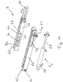
- FIG. 2 shows a detail view of FIG. 1 from the region of the coupling of the main boom extension 1 to the main boom 2.
- the main boom extension 1 having a rectangular cross section in the usual manner is fastened to the main boom 2 via four bolt connections arranged in the corner regions of the main boom extension 4 at bolting points A, B, C and D.
- the lower right-hand bolted connection at the bolting point C is concealed by the main boom 2, but formed identically to the bolted connection at the bolting point D.
- Each of the four bolt connections is called formed two-pin bolt connection, which is constructed in a corresponding manner substantially of a forked tongue 4a, a tab 4b and a bolt 4c.
- the forked tongue 4 a with its two opposite bores for the bolt 4 c is fastened in each case in the four bolting points A to D to a foot 1 c of the main boom extension 1 and in extension of the main boom extension 1.
- the holes in the fork lug 4 a are aligned vertically with horizontal main boom extension 1.
- the tab 4b is fixed to the main boom head 2a via an axle 4d.
- the axis 4d is aligned horizontally and transversely to the longitudinal direction of the main boom 2 with horizontal main boom head 2a and rotatably supported in the main boom head 2a.
- the tab 4b is also rotatable about the horizontal axis 4d.
- the tab 4b has a bore which is aligned with the holes of the fork tab 4a.
- a bolt 4c is inserted to fix the main boom extension 1 to the main boom head 2a in a corresponding manner.
- the main boom extension 1 In order to be able to angle the main boom extension 1 relative to the main boom head 2a or main boom 2, it is provided to pull the two upper bolts 4c at the bolting points A and B in the region of a top belt 1d of the main boom extension 1 so that the main boom extension 1 relative to the main boom 2 about the lower axis 4d in the region of the lower Verbolzungsstellen C and D in the region of a lower chord 1e of the main boom extension 1 by the angle of deflection b can bend.
- the lower axis 4d thus forms the rocking axis w. Instead of the axis 4d could also serve the bolt 4c, if they were aligned horizontally.
- the angle of deflection b is usually in the range of 0 ° to 40 °.
- angled lugs 5 are provided, of which one is designed as an active combination angle lug 6.
- the Abwinkellasche 5 and the combination Abwinkellasche 6 extend in the region of the longitudinal sides of the upper belt 1d of the main boom extension 1 and parallel to each other.
- the passive Abwinkellasche 5, on the manual over a stop surface 5a a displacement and thus the Abwinkelwinkel b is limited, consists essentially of a sliding tab 5b with a slot-shaped Guide opening 5c, on which a guide plate 5d in the longitudinal direction c along a sliding latch 5b can be guided.
- the sliding lug 5b is formed as an elongated flat profile with the stop opening 5c and extends substantially parallel to the longitudinal direction v of the main boom extension 1.
- the sliding lug 5b has a bore through which the sliding lug 5b with a bolt 5e on the Main boom head 2a at the Verbolzungsstelle E is releasably attached.
- the bolt 5e is aligned with its longitudinal extent parallel to the axis 4d.
- the guide plate 5d is pushed, which for this purpose has a closed rectangular cross-section with a guide opening 5f (see FIG. 5 ), in which the sliding plate 5b is inserted and guided.
- the guide plate 5d per se is detachably fastened to the main boom 1a of the main boom extension 1 at a end facing the main boom head 2a via a further pin 5i in a bolting point G.
- the pin 5i is aligned with its longitudinal extent parallel to the axis 4d. Also, the pin 5i is passed through the stopper opening 5c of the sliding tab 5b.
- two continuous stop holes 5g spaced apart from each other in the longitudinal direction of the guide plate 5d are arranged in the side parts of the guide plate 5d.
- a first of the two stop holes 5g serves to limit the angle of deflection b to 20 ° and a second to 40 °.
- the stopper holes 5g for 40 ° are correspondingly located closer to the main boom head 2a to allow a larger displacement.
- a stop pin is inserted into the respective stop hole 5g, which then passes through the two opposite stop holes 5g and the intermediate stop opening 5c.
- the stop pin 5h inserted into the second of the two stop holes 5g, which limits the angle of deflection b to 40 °.
- the stopper bolt 5h is guided adjacent to the pin 5i in the stopper opening 5c.
- the bolt 5i would come into contact only with the opposing abutment surface 5a of the stopper opening 5c when no stopper bolt 5h is inserted.
- the second of the two stop holes 5g is free.
- the active combination Abwinkellasche 6 is comparable to the structure of the manual part with the above-described passive Abwinkellasche 5 and has a stop surface 6a, a sliding tab 6b, a stop opening 6c, a corresponding manner Guide plate 6d, a bolt 6e, a guide hole 6f, a stopper hole 6g, a stop pin 5h corresponding stop pin 6h, which is also referred to as a bolt 6p, and a bolt 6i on.
- the stopper bolt 6h and the bolt 6p are the same in the embodiment and provided only with respect to their Einsteckort with different terms and reference numerals.
- the bolt 6e is releasably secured in a Verbolzungsstelle F to the main boom head 2a and the bolt 6i at a Verbolzungsstelle H.
- the stop pin 6h is not plugged in the normal position with the Abwinkelwinkel b of 0 °.
- the active combination Abwinkellasche 6 is supplemented by a drive 6j to actively move the guide plate 6d relative to the sliding tab 6b can.
- the sliding lug 6d is provided at its end opposite the main boom head 2a with a connection angle 6m at which the angle drive 6j is connected on the housing side to two hydraulic cylinders running parallel to one another with housings 6k and rod 6l.
- the hydraulic cylinders extend in the longitudinal direction of the Abwinkellasche 5 or combi Abwinkellasche 6.
- the sliding latch 6b extended with a rod portion 6n to form a repository for the Abwinkelantrieb 6j.
- a bore 6o (see FIG. 3 ) is arranged to attach via a further bolt 6p a coupling part 6q, on which the rods 6l of the hydraulic cylinders or Abwinkelantriebe 6j are stored.
- the hydraulic cylinders can be connected, for example, to existing hydraulic circuits. Basically, this is the hydraulic circuit of a Beiziehzylinders for horizontal pivoting a entrained main boom extension from a transport position out.
- the Abwinkelantrieb 6j is dimensioned so that only the weight of the Main boom extension 1 off or can be angled.
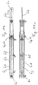
- FIG. 3 shows an exploded view of a combination Abwinkellasche FIG. 2 , It can be seen that the coupling part 6q has a total of three holes in order to receive the bolt 6p and the ends of the rods 6l of the Abwinkelantriebs 6j and thus redirect the force between the sliding tab 6b and the guide plate 6d. In addition, in the FIG. 3 the stop pin 6h shown.
- FIG. 4a is a detail view of a combination Abwinkellasche 6 in the position according to FIG. 1 shown.
- the Abwinkelantrieb 6j is extended, ie the rod 6l is moved out by a Ausfahrweg d from the housing 6k.
- This extension d corresponds to the in FIG. 1 illustrated basic position between the main boom extension 1 and main boom 2.
- the Abwinkelantrieb 6j can be further extended to reduce the distance between the Verbolzungsstellen G, H and E, F. This then leads to a relief of the upper pin 4c at the Verbolzungsstellen A, B.
- the Abwinkelantrieb 6j is coupled to the sliding tab 6b, since the pin 6p is inserted.
- FIG. 4b shows a side view of FIG. 4a with the drawn extension path d.
- FIG. 5 is a sectional view of FIG. 4b shown along the section line BB. It can be seen that the guide lug 6d has a rectangular cross section with a central guide opening 6f, in which the sliding lug 6b is guided with its stop opening 6c.
- the main boom extension 1 is now based on the two lower pin 4c in combination with the combination Abwinkellasche 6 on the main boom 2 from.
- the two lower bolts 4c and the axle 4d which is also a lower roller head axle, thus form the teetering axle w for the angling of the main boom extension 1.
- the Abwinkelantrieb 6j is operated again and the rods 6l of the hydraulic cylinders retracted slowly.
- the sliding lug 6b is pushed relative to the guide lug 6d via the coupling part 6q in the direction of the main boom 2, so that the distance between the Verbolzungslitis G, H and E, F increases and the main boom extension 1 via the arranged in the region of the lower chord 1d axis 4d of the bolting points C, D pivots by the angle of deflection b.
- the head 1 f of the main boom extension 1 lowers in the direction of the bottom 3 until it touches the bottom 3.
- the Abwinkelantrieb 6j is now retracted a little further, whereby the bolt 6p relieved in the bore 6o and then plugged as a stop pin 6h in the stop hole 6g.
- This has the advantage that it is not forgotten during the set-up process to decouple the Abwinkelantrieb 6j and lifting this load is no longer involved in the main power flow.
- the desired maximum displacement is now set before or at the latest now also at the Abwinkellasche 5 to allow or limit the bending of the main boom extension 1 in the 20 ° -dietary mesh 40 ° -position.
- FIG. 6 Following the main boom extension 1 FIG. 1 in a 15 ° position, the previously described position is shown, in which the lowered head 1f is supported on the floor 3.
- the rocking angle a of the main boom 2 is still 0 °.
- the Figure 7a shows a detailed view of the combination Abwinkellasche 6 in the 15 ° position according to FIG. 6 , It is shown that the rods 6l of the hydraulic cylinder are fully retracted and the coupling part 6q continues to be connected via the bolt 6p to the rod part 6n of the sliding latch 6b. Now, as the tip 1f rests on the bottom 3, the bolt 6p is pulled, thus releasing the bending drive 6j from the combination bending-back pocket 6, which thus also becomes a passive bending-off pocket.
- FIG. 7b is a side view of Figure 7a shown.
- the main boom extension 1 is further angled by a rocking of the main boom 2 by the luffing angle a and the tip 1f of the main boom extension 1 slides through the bottom 3 in the direction of the main boom 2.
- the main boom extension 1 is further angled until the Abwinkellasche 5 and the combination Abwinkellasche 6 limit the bending in a preselected position.
- the Abwinkelzi in the 40 ° position by the Abwinkellasche 5 and the combination Abwinkellasche 6 tip 1f just has contact with the ground 3.
- a further Auflippen of the main boom 2 then lifts the main boom extension 1 from the bottom 3 in from the 40 ° position.
- This position, in which the main boom extension 1 to the main boom 2 is in a 40 ° position, is in the FIG. 8 shown.
- the tip 1b of the main boom extension 1 is not shown there.
- FIG. 9a is a detail view of a combination Abwinkellasche 6 in the position according to FIG. 8 shown.
- the stopper bolt 6h is in the stopper hole 6g, which faces the main boom 2a, so as to limit the maximum displacement possibility of the guide plate 6d on the slide plate 6b.
- the stopper bolt 6h abuts the stopper surface 6a at the end of the stopper opening 6c. Since the stopper bolt 6h is inserted into the stopper hole 6g closer to the main boom head 2a, the angle of angling b is limited to 40 °.
- the Abwinkelantrieb 6j is further decoupled, since the pin 6p is not plugged.
- FIG. 9b shows a side view of FIG. 9a .
- a backward or upright of the main boom extension 1 takes place in the reverse order.
- FIG. 10 an exploded view of a combination Abwinkellasche 6 is shown in an alternative embodiment, which is currently preferred.
- the active combi Abwinkellasche 6 is comparable to the structure with the above-described active combination Abwinkellasche 6 and has in a corresponding manner a sliding tab 6b, a guide plate 6d and a Abwinkelantrieb 6j.
- this sliding lug 6b is not flat-profile over its entire length, but at least in the region of the stop opening 6c and the bore 6o of two parallel and spaced-apart flat-profile sliding lug parts 6b '
- the sliding tab 6b also has a hole 6o adjacent to the stop opening 6c in the region of its center in order to detach the rod 6l of the angular drive 6j with the sliding tab 6b via the pin 6p
- This bore 6o also serves as a stop surface 6a 'for the stop pin 6h or pin 6p in the 20 ° position FIG. 10 shown bolt without reference number is without function.
- the associated hole can be used to store currently unused bolts.
- the guide plate 6d according to FIG. 10 is comparable to the above-described, wherein the guide opening 6f is formed correspondingly wider to accommodate the wider sliding tab 6b.
- the guide opening 6f is formed correspondingly wider to accommodate the wider sliding tab 6b.
- two stop holes 6g in the guide plate 6d only one slot-shaped stop opening 6g 'is present.
- the illustrated bolt 6p, 6h can be used either to connect the Abwinkelantriebs 6j to the sliding tab 6b or limiting the displacement of the guide plate 6d along the sliding tab 6b.
- the Abwinkelantrieb 6j in the form of a single Hydraulic cylinder with housing 6k and rod 6l shown.
- the hydraulic cylinder can be connected via the bolt 6p, if necessary, to the bore 6o of the sliding lug 6b.
- the housing 6k of the hydraulic cylinder is connected together with the guide lug 6d in the attachment point H to a lug of the foot 1c of the main boom extension 1 with the bolt 6i.
- the tab will be located farther away from the main boom head 2a, since the flow of force through the combi-angled lobe 6 will be as shown in FIG FIG. 10 from the combi Abwinkellasche 6 in FIG. 2 different.
- FIG. 11a shows a detailed view of a combined Kombi-Abwinkellasche 6 according to FIG. 10 , It can be seen that the angled drive 6j is arranged in the sliding lug 6b between the two sliding lug parts 6b 'and 6b ".
- the sliding lug parts 6b' and 6b" are correspondingly guided in the guide opening 6f of the guide lug 6d.
- the sliding lug 6b is displaceable relative to the guide lug 6d via the coupled Abwinkelantrieb 6j or decoupled Abwinkelantrieb 6 on the weight of the main boom extension 1.
- FIG. 11b shows a side view of FIG. 11a
- main boom 2 is described as a telescopic boom and the main boom extension 1 as a lattice boom lattice boom, the invention is also applicable to other configurations of main boom 2 and main boom extension 1.
- the main boom 2 may also be a lattice boom or a combination of telescopic boom, lattice boom and / or box boom.
- main boom extension 1 lattice boom or box boom or combinations thereof are conceivable.
- the embodiment is based on the use of a Abwinkellasche 5 and a combination Abwinkellasche 6. It is also possible instead of a Abwinkellasche 5 and a combination Abwinkellasche 6 two each arranged in the edge region of the upper belt 1d of the main boom extension 1 combination Abwinkellaschen 6 provide. This embodiment with two combination Abwinkellaschen 6 without a Abwinkellasche 5 is preferred. Also, the use of a single and centrally relative to the width of the upper belt 1d of the main boom extension 1 arranged combination Abwinkellasche 6 is conceivable. Furthermore, the combination Abwinkellasche 6 has been described as a pull rod. A design as a push bar also works and an arrangement in the lower flange area.
- rocking w is arranged in the region of the upper flange 1d.
- the foot 1c of the main boom extension 1 is chamfered accordingly, preferably in the form of an adapter to allow bending of the main boom extension 1 about the upper luffing axis w.
Landscapes
- Engineering & Computer Science (AREA)
- Mechanical Engineering (AREA)
- Jib Cranes (AREA)
Description
- Die Erfindung betrifft einen Mobilkran mit einem wippbar hieran gelagerten und über einen Wippzylinder aufrichtbaren Hauptausleger und mit einer lösbar an einem Hauptauslegerkopf des Hauptauslegers über obere und untere Bolzen verbundenen Hauptauslegerverlängerung, die Hauptauslegerverlängerung ausgehend von einer Grundstellung nach einem Lösen der oberen oder unteren Bolzen mittels eines Abwinkelantriebs um eine Wippachse relativ zu dem Hauptausleger abwinkelbar ist, der Abwinkelantrieb Bestandteil einer Abwinkellasche in Form einer Kombi-Abwinkellasche ist, der Abwinkelantrieb einerseits an dem Hauptauslegerkopf und andererseits an einem Fuß der Hauptauslegerverlängerung angreift, ein maximaler Abwinkelwinkel durch eine einstellbare Abwinkellasche begrenzt ist, die Abwinkellasche an dem Fuß der Hauptauslegerverlängerung und dem Hauptauslegerkopf angreift und die Kombi-Abwinkellasche aus einer Schiebelasche, einer Führungslasche und dem Abwinkelantrieb besteht.
- Auch betrifft die Erfindung ein Verfahren zum Abwinkeln einer Hauptauslegerverlängerung relativ zu einem Hauptausleger eines Mobilkrans.
- Aus dem deutschen Gebrauchsmuster
DE 20 2004 020 760 U1 ist bereits ein Mobilkran mit einem Hauptausleger und einer an seinem Hauptauslegerkopf befestigten Hauptauslegerverlängerung bekannt. Die Hauptauslegerverlängerung ist aus einer Grundstellung, in der die Hauptauslegerverlängerung mit ihrer Längsrichtung in Verlängerung der Längsrichtung des Hauptauslegers ausgerichtet ist, in eine 20°-Stellung und eine 40°-Stellung wippbar. Die Hauptauslegerverlängerung ist in üblicher Weise über zwei untere im Bereich von Untergurten der Hauptauslegerverlängerung und zwei obere im Bereich von Obergurten der Hauptauslegerverlängerung angeordnete Bolzen lösbar an dem Hauptauslegerkopf befestigt. Um die Hauptauslegerverlängerung um die als Wippachse dienenden unteren beiden Bolzen aus der Grundstellung heraus wippen zu können, werden in einem ersten Schritt die beiden oberen Bolzen gezogen und in einem zweiten Schritt über hydraulische Wippzylinder, die an dem Hauptauslegerkopf und an der Hauptauslegerverlängerung angreifen, das Wippen der Hauptauslegerverlängerung bewirkt. Das Stecken und Ziehen der beiden oberen Bolzen erfolgt jeweils über einen hydraulischen Verbolzungszylinder. Zur Versorgung der Wippzylinder und der Verbolzungszylinder ist ein autarkes Hydraulikaggregat an dem unteren Ende der Hauptauslegerverlängerung angeordnet. Als Hydraulikaggregat kann beispielsweise ein Dieselmotor oder Elektromotor jeweils mit einer zugehörigen Hydraulikpumpe zum Einsatz kommen. - Auch ist aus der deutschen Patentschrift
DE 103 21 493 B4 ein Mobilkran mit einer Hauptauslegerverlängerung und einer Abwinkellasche bekannt. Die Abwinkellasche ist als mechanisch feststellbare Teleskopierungsvorrichtung ausgebildet mit einer rohrförmigen Führungslasche und einer hierin geführten und ausfahrbaren Schiebelasche, die ebenfalls rohrförmig ist. Die Führungslasche weist Anschlagöffnungen zur Aufnahme von Bolzen auf, die für eine Abstützung der Schiebelasche an seinem unteren Ende sorgen und somit eine vorgewählte Länge der Abwinkellasche und somit Winkeleinstellung der Hauptauslegerverlängerung ermöglichen. Die Abwinkellasche ist im Bereich eines Untergurtes des Hauptauslegers und der Hauptauslegerverlängerung angeordnet. Die gewünschte Abwinkelung wird durch Anheben des Hauptauslegers erreicht, wodurch sich die Abwinkellasche solange verkürzt, bis die Schiebelasche auf den Bolzen trifft und daran abgestützt wird. - Außerdem offenbart die europäische Patentanmeldung
EP 2 253 576 A1 eine andere Ausführungsform einer Abwinkellasche zur Abwinkelung einer Hauptauslegerverlängerung von Mobilkranen. Die aus zwei Winkelhebeln ausgebildete Abwinkellasche weist in ihrer Grundstellung, die einer 0°-Stellung der Hauptauslegerverlängerung zu dem Hauptausleger entspricht, mehrere Paare fluchtender Anschlagöffnungen für Bolzen auf. Über eine Wahl eines Paares der Anschlagöffnungen für die Bolzen kann die Länge der Abwinkellasche variiert werden und die Hauptauslegerverlängerung in verschiedene Winkelstellungen, vorzugsweise 0°, 20° und 40°, festgelegt werden. Die eigentliche Abwinkelbewegung der Hauptauslegerverlängerung erfolgt mittels einer am Kran oder neben dem Kran befindlichen Hebemaschine. - Die französische Patentanmeldung
FR 2 719 574 - Das Patent
US 4,828,124 offenbart eine Hauptauslegerverlängerung, die an einem Hauptausleger angelenkt ist und einen Rahmen, einen Auslegergrundkörper sowie zwei Hydraulikzylinder aufweist. Jeder der Hydraulikzylinder ist über einen ersten Bolzen an den Rahmen und über einen weiteren Bolzen an den Auslegergrundkörper angelenkt. Die Hydraulikzylinder dienen zur Steuerung der Position der Hauptauslegerverlängerung relativ zum Hauptausleger. - Die Offenlegungsschrift
DE 10 2012 023 814 A1 beschreibt einen Mobilkran mit Klappspitze sowie ein Verfahren zum Verschwenken der Klappspitze. Die Klappspitze ist derart ausgeführt, dass ein Hydraulikzylinder bereitgestellt ist, mittels dem ein vorderer Teil der Klappspitze um eine horizontale Achse wippbar ist. Es kann statt eines aktiven Hydraulikzylinders auch eine passive Verstelllasche verwendet werden. - Die europäische Patentanmeldung
EP 1 081 088 A1 betrifft einen Teleskopkran mit einem Hauptausleger und einem hydraulischen Zylinder zum Wippen des Hauptauslegers relativ zum Teleskopmast des Teleskopkrans. - Die deutsche Patentanmeldung
DE 10 2014 003831 A1 beschreibt ein Kransystem mit einem Hauptausleger und einem Spitzenausleger, wobei zum Wippen des Spitzenauslegers ein Verstellantrieb verwendet wird. Der Verstellantrieb ist über Adapter am Hauptausleger und am Spitzenausleger angebracht und ist als elektrischer oder hydraulischer Motor und explizit nicht als hydraulischer Zylinder ausgeführt. - Ferner betrifft die japanische Patentanmeldung
JP H09 104 588 A - Der Erfindung liegt die Aufgabe zu Grunde, einen Mobilkran und Verfahren zum Abwinkeln einer Hauptauslegerverlängerung relativ zu einem Hauptausleger eines Mobilkrans zu schaffen, mit denen das Abwinkeln der Hauptauslegerverlängerung vereinfacht wird.
- Diese Aufgabe wird durch einen Mobilkran mit den Merkmalen des Anspruchs 1 und durch ein Verfahren mit den Merkmalen des Anspruchs 8 gelöst. Vorteilhafte Ausgestaltungen der Erfindung sind in den Unteransprüchen 2 bis 7 und 9 angegeben.
- Erfindungsgemäß wird bei einem Mobilkran mit einem wippbar hieran gelagerten und über einen Wippzylinder aufrichtbaren Hauptausleger und mit einer lösbar an einem Hauptauslegerkopf des Hauptauslegers über obere und untere Bolzen verbundenen Hauptauslegerverlängerung, die Hauptauslegerverlängerung ausgehend von einer Grundstellung nach einem Lösen der oberen Bolzen oder der unteren Bolzen mittels eines Abwinkelantriebs um eine Wippachse relativ zu dem Hauptausleger abwinkelbar ist, der Abwinkelantrieb Bestandteil einer Abwinkellasche in Form einer Kombi-Abwinkellasche ist, der Abwinkelantrieb einerseits an dem Hauptauslegerkopf und andererseits an einem Fuß der Hauptauslegerverlängerung angreift, ein maximaler Abwinkelwinkel durch eine einstellbare Abwinkellasche begrenzt ist, die Abwinkellasche an dem Fuß der Hauptauslegerverlängerung und dem Hauptauslegerkopf angreift und die Kombi-Abwinkellasche aus einer Schiebelasche, einer Führungslasche und dem Abwinkelantrieb besteht, dadurch eine Vereinfachung erreicht, dass der Abwinkelantrieb antriebsmäßig einerseits an der Schiebelasche und andererseits an der Führungslasche angreift und über den Abwinkelantrieb die Schiebelasche relativ zu der Führungslasche verschiebbar ist.
- . Vorteilhafter Weise wird somit eine bekannte passive mechanisch begrenzende Abwinkellasche in eine hydraulisch unterstützte Kombi-Abwinkellasche, die auch die mechanische Begrenzung bereitstellt, umgewandelt. Durch die Integration des Abwinkelantriebes in die Kombi-Abwinkellasche sind keine zusätzlichen Krafteinleitungspunkte am Hauptauslegerkopf oder der Hauptauslegerverlängerung erforderlich. Das Abwinkeln an sich erfolgt weitestgehend am Boden beziehungsweise der Ablagestellung des Hauptauslegers, so dass es nicht erforderlich ist, weit oberhalb der Oberkante des Mobilkrans zu arbeiten. Die Erfindung erlaubt das Abwinkeln der Hauptauslegerverlängerung bei auf einem ebenen Boden stehendem Mobilkran mit horizontal ausgerichtetem Teleskopausleger. Für den letzten Teil des Aufwippens der Hauptauslegerverlängerung in eine 20°-beziehungsweise 40°-Stellung wird der Wippzylinders des Hauptauslegers zu Hilfe genommen. Da der Ausfahrweg des Hydraulikzylinders des Abwinkelantriebs frei gewählt werden kann, kann bei einem länger gewählten Ausfahrweg der Abwinkelantrieb relativ geländeunabhängig ausgestaltet werden.
- Da die Kombi-Abwinkellasche im Bereich des Fußes der Hauptauslegerverlängerung angreift ist kein Gabelkopfversatz zwischen Hauptausleger und Hauptauslegerverlängerung erforderlich, der eine Verformung der Hauptauslegerverlängerung ausgleicht. Die ist insbesondere bei langen schmalen Ausleger-Systemen wichtig. Auch ist hierdurch kein Hilfszylinder erforderlich, über den ein Gabelkopf-Versatz kompensiert werden muss.
- Erfindunfgsgemäß ist vorgesehen, dass der Abwinkelantrieb einerseits an dem Hauptauslegerkopf und andererseits an der Hauptauslegerverlängerung angreift. Hierbei ist insbesondere der Abwinkelantrieb derart ausgebildet, dass die Hauptauslegerverlängerung entgegen der Schwerkraftwirkung der Hauptauslegerverlängerung um die Wippachse schwenkend anhebbar und absenkbar ist.
- In einer vorteilhaften Ausgestaltung ist vorgesehen, dass ausgehend von einer Grundstellung nach einem Lösen der oberen Bolzen die Hauptauslegerverlängerung mittels des Abwinkelantriebs um eine Wippachse im Bereich eines Untergurts der Hauptauslegerverlängerung abwinkelbar ist und der Abwinkelantrieb im Bereich des Obergurts der Hauptauslegerverlängerung angreift.
- Besonders vorteilhaft ist, dass der Abwinkelantrieb als Hydraulikzylinder mit Gehäuse und Stange ausgebildet ist.
- In konstruktiv einfacher und erfindungsgemäßer Ausgestaltung ist vorgesehen, dass die Kombi-Abwinkellasche aus einer Schiebelasche, einer Führungslasche und dem Abwinkelantrieb besteht, der Abwinkelantrieb antriebsmäßig einerseits an der Schiebelasche und andererseits an der Führungslasche angreift und über den Abwinkelantrieb die Schiebelasche relativ zu der Führungslasche verschiebbar ist. Hierbei ist insbesondere der Abwinkelantrieb lösbar an der Schiebelasche befestigt. Besonders bevorzugt ist die Schiebelasche schwenkbar an dem Hauptauslegerkopf gelagert, die Führungslasche schwenkbar an der Hauptauslegerverlängerung gelagert, die Schiebelasche in der Führungslasche geführt und über einen Anschlagbolzen eine maximale Verschiebung der Schiebelasche in der Führungslasche begrenzbar.
- Erfindungsgemäß wird bei einem Verfahren zum Abwinkeln einer Hauptauslegerverlängerung relativ zu einem Hauptausleger eines Mobilkrans, insbesondere eines vorbeschriebenen Mobilkrans, wobei der Hauptausleger wippbar an dem Mobilkran gelagert und über einen Wippzylinder aufrichtbar ist, die Hauptauslegerverlängerung lösbar an einem Hauptauslegerkopf des Hauptauslegers über obere und untere Bolzen verbunden ist, ein Abwinkelantrieb an einem Fuß der Hauptauslegerverlängerung angreift, ein maximaler Abwinkelwinkel durch eine einstellbare Abwinkellasche begrenzt ist und die Abwinkellasche an dem Fuß der Hauptauslegerverlängerung und dem Hauptauslegerkopf angreift, eine Vereinfachung dadurch erreicht, dass mittels des Abwinkelantriebs, der Bestandteil einer Abwinkellasche in Form einer Kombi-Abwinkellasche ist, die Hauptauslegerverlängerung ausgehend von einer Grundstellung um eine Wippachse relativ zu dem Hauptausleger angehoben wird, soweit bis die oberen oder unteren Bolzen entlastet werden, dann die oberen oder unteren Bolzen entfernt werden, zwischen dem Hauptauslegerkopf und einem Obergurt beziehungsweise Untergurt der Hauptauslegerverlängerung mindestens eine Kombi-Abwinkellasche eingesetzt wird beziehungsweise bereits eingesetzt ist, mittels des Abwinkelantriebs die Hauptauslegerverlängerung abgesenkt wird, solange bis die maximale Abwinkelstellung erreicht wird oder ein Kopf der Hauptauslegerverlängerung auf einem Boden zur Auflage kommt, der Abwinkelantrieb antriebsmäßig von der Kombi-Abwinkellasche getrennt wird und wenn die maximale Abwinkelstellung noch nicht erreicht ist, mittels Aufrichten des Hauptauslegers die Hauptauslegerverlängerung bis zum Erreichen des gewünschten Abwinkelwinkels abgewinkelt wird. In Bezug auf die hiermit verbundenen Vorteile wird auf die Ausführungen zuvor für den Mobilkran verwiesen.
- Vorzugsweise ist vorgesehen, dass die Hauptauslegerverlängerung ausgehend von einer Grundstellung um eine Wippachse relativ zu dem Hauptausleger angehoben wird, soweit bis die oberen Bolzen entlastet werden, dann die oberen Bolzen entfernt werden, zwischen dem Hauptauslegerkopf und einem Obergurt der Hauptauslegerverlängerung mindestens eine Kombi-Abwinkellasche eingesetzt wird beziehungsweise bereits eingesetzt ist.
- Im Zusammenhang mit der vorliegenden Erfindung wird unter einem Mobilkran sowohl ein verfahrbarer Teleskopkran als auch ein verfahrbarer Raupenkran mit Gittermastausleger verstanden.
- Nachfolgend wird die Erfindung an Hand eines in einer Zeichnung dargestellten Ausführungsbeispiels näher erläutert. Es zeigen:
-
Figur 1 eine Seitenansicht einer Hauptauslegerverlängerung in einer Grundstellung an einem Hauptausleger, -
Figur 2 eine Detailansicht vonFigur 1 aus dem Bereich der Ankopplung der Hauptauslegerverlängerung an den Hauptausleger, -
Figur 3 eine Explosionsdarstellung einer Kombi-Abwinkellasche ausFigur 2 , -
Figur 4a eine Detailansicht auf eine Kombi-Abwinkellasche in der Stellung gemäßFigur 1 , -
Figur 4b eine Seitenansicht vonFigur 4a , -
Figur 5 eine Schnittansicht vonFigur 4b entlang der Schnittlinie B-B, -
Figur 6 den Hauptausleger nachFigur 1 mit der Hauptauslegerverlängerung in einer 15°-Stellung, -
Figur 7a eine Detailansicht auf eine Kombi-Abwinkellasche in der Stellung gemäßFigur 6 , -
Figur 7b eine Seitenansicht vonFigur 7a , -
Figur 8 den Hauptausleger nachFigur 1 mit der Hauptauslegerverlängerung in einer 40°-Stellung, -
Figur 9a eine Detailansicht auf eine Kombi-Abwinkellasche in der Stellung gemäßFigur 8 , -
Figur 9b eine Seitenansicht vonFigur 9a , -
Figur 10 eine Explosionsdarstellung einer Kombi-Abwinkellasche in einer alternativen Ausgestaltung, -
Figur 11a eine Detailansicht einer zusammen gefügten Kombi-Abwinkellasche gemäßFigur 10 und -
Figur 11b eine Seitenansicht vonFigur 11a . - In der
Figur 1 ist eine Seitenansicht einer Hauptauslegerverlängerung 1 in Grundstellung an einem Hauptausleger 2 dargestellt. Der Hauptausleger 2 ist als Teleskopausleger mit einem Grundkasten 2b und entsprechenden Teleskopschüssen 2c ausgebildet. An dem freien Ende des innersten Teleskopschusses 2c ist ein Hauptauslegerkopf 2a vorgesehen. Der Hauptausleger 2 ist Bestandteil eines nicht dargestellten Teleskopkrans und ist in üblicher Weise über einen hydraulischen Wippzylinder 7, der sich an einem Oberwagen 8 des Teleskopkrans abstützt, aufrichtbar. Der Oberwagen 8 ist nur durch ein Rahmenteil hiervon inFigur 1 angedeutet. In derFigur 1 sind die Hauptauslegerverlängerung 1 und der Hauptausleger 2 in einer sogenannten abgelegten Stellung gezeigt, in der die Hauptauslegerverlängerung 1 mit ihrer Längsrichtung v und der Hauptausleger 2 mit seiner Längsrichtung h im Wesentlichen horizontal ausgerichtet sind. Ein sogenannter Wippwinkel a des Hauptauslegers 2 relativ zu dem Oberwagen 8 beträgt somit in der abgelegten Stellung 0°. Mit dem Wippwinkel a wird das Aufrichten des Hauptauslegers 2 relativ zu dem Oberwagen 8 beschrieben. An dem Hauptauslegerkopf 2a ist die Hauptauslegerverlängerung 1 über eine Bolzenverbindung lösbar befestigt. Die Hauptauslegerverlängerung 1 kann vorübergehend oder ständig mit dem Teleskopkran genutzt werden, um eine über die größte Auslegerlänge des Hauptauslegers 2 hinausgehende noch größere Gesamtlänge des Auslegers zu erzielen. - Diese Hauptauslegerverlängerung 1 ist geteilt in einen als Gittermast ausgebildeten Grundausleger 1a, der in üblicher Weise eine Fachwerk-Rohrkonstruktion ist, und einer sich hieran anschließenden Spitze 1b, die als Kastenausleger ausgebildet ist. Der Hauptausleger 2 und die Hauptauslegerverlängerung 1 befinden sich in der
Figur 1 in einer 0°-Stellung beziehungsweise Grundstellung, in der die Längsrichtung h des Hauptauslegers 1 und die Längsrichtung v der Hauptauslegerverlängerung 1 miteinander fluchten beziehungsweise parallel zueinander verlaufen. Ein entsprechender Abwinkelwinkel b ist daher 0°. Die Hauptauslegerverlängerung 1 ist zu dem Hauptausleger 2 um eine Wippachse w wippbar, die von einer unteren Rollkopfachse gebildet wird. Die Hauptauslegerverlängerung 1 ist in dieser Grundstellung von einem Boden 3 mit ersten bis dritten Bodenniveaus 3a bis 3c beabstandet und wird somit von dem Hauptausleger 2 über die Bolzenverbindungen in entsprechenden Verbolzungsstellen A, B, C und D (sieheFigur 2 ) an dem Hauptauslegerkopf 2a getragen. - Derartige Hauptauslegerverlängerungen 1 sind grundsätzlich als Baukastensysteme aus einzelnen Hauptelementen aufgebaut und können je nach Erfordernis an deren Länge beziehungsweise Tragkraft zusammengestellt werden. Die einzelnen Hauptelemente weisen transportfähige Abmessungen und werden in den meisten Fällen nicht mit dem Teleskopkran mitgeführt, sondern werden separat transportiert. Wenn es die Achslasten des Teleskopkrans und die Baugröße der Hauptauslegerverlängerung 1 zulassen, kann bei Bedarf die Hauptauslegerverlängerung 1 mitgeführt werden. Diese würde sich dann in einer Transportstellung seitlich neben und parallel zu dem Hauptausleger 2 befinden. Eine Verbindung der einzelnen Hauptelemente aneinander zu der gewünschten Hauptauslegerverlängerung 1 erfolgt über Bolzenverbindungen. Der Anbau an den Hauptauslegerkopf 2a kann hauptelementweise oder als vormontierte Einheit beziehungsweise Einheiten erfolgen.
- Die
Figur 2 zeigt eine Detailansicht vonFigur 1 aus dem Bereich der Ankopplung der Hauptauslegerverlängerung 1 an den Hauptausleger 2. Die in üblicher Weise einen rechteckigen Querschnitt aufweisende Hauptauslegerverlängerung 1 ist über vier in den Eckbereichen der Hauptauslegerverlängerung 4 angeordnete Bolzenverbindungen an Verbolzungsstellen A, B, C und D an dem Hauptausleger 2 befestigt. Die untere rechte Bolzenverbindung an der Verbolzungstelle C ist von dem Hauptausleger 2 verdeckt, aber identisch zu der Bolzenverbindung an der Verbolzungstelle D ausgebildet. Jede der vier Bolzenverbindungen ist als sogenannte zweischnittige Bolzenverbindung ausgebildet, die in entsprechender Weise im Wesentlichen aus einer Gabellasche 4a, einer Lasche 4b und einem Bolzen 4c aufgebaut ist. Die Gabellasche 4a mit ihren beiden gegenüberliegenden Bohrungen für den Bolzen 4c ist jeweils in den vier Verbolzungsstellen A bis D an einem Fuß 1c der Hauptauslegerverlängerung 1 und in Verlängerung der Hauptauslegerverlängerung 1 befestigt. Hierbei sind die Bohrungen in der Gabellasche 4a bei horizontaler Hauptauslegerverlängerung 1 vertikal ausgerichtet. Die Lasche 4b ist über eine Achse 4d an dem Hauptauslegerkopf 2a befestigt. Die Achse 4d ist bei horizontal ausgerichtetem Hauptauslegerkopf 2a horizontal und quer zur Längsrichtung des Hauptauslegers 2 ausgerichtet und drehbar in dem Hauptauslegerkopf 2a gelagert. Entsprechender Weise ist jeweils die Lasche 4b auch um die horizontale Achse 4d drehbar. Auch die Lasche 4b weist eine Bohrung auf, die mit den Bohrungen der Gabellasche 4a fluchtet. In die Bohrungen der Lasche 4b und die der Gabellasche 4a ist ein Bolzen 4c eingesteckt, um in entsprechender Weise die Hauptauslegerverlängerung 1 an dem Hauptauslegerkopf 2a zu befestigen. - Um die Hauptauslegerverlängerung 1 relativ zu dem Hauptauslegerkopf 2a beziehungsweise Hauptausleger 2 abwinkeln zu können, ist vorgesehen, die beiden oberen Bolzen 4c an den Verbolzungsstellen A und B im Bereich eines Obergurts 1d der Hauptauslegerverlängerung 1 zu ziehen, damit die Hauptauslegerverlängerung 1 relativ zu dem Hauptausleger 2 um die untere Achse 4d im Bereich der unteren Verbolzungsstellen C und D im Bereich eines Untergurts 1e der Hauptauslegerverlängerung 1 um den Abwinkelwinkel b abwinkeln kann. Die untere Achse 4d bildet somit die Wippachse w. Anstelle der Achse 4d könnten auch die Bolzen 4c dienen, wenn diese horizontal ausgerichtet wären. Der Abwinkelwinkel b liegt üblicher Weise im Bereich von 0° bis 40°. Um den Abwinkelwinkel b zu begrenzen beziehungsweise auf die üblichen Werte von 20° und 40° Abwinkelwinkel einstellen zu können, sind zwei sogenannte Abwinkellaschen 5 vorgesehen, von denen eine als aktive Kombi-Abwinkellasche 6 ausgebildet ist. Die Abwinkellasche 5 und die Kombi-Abwinkellasche 6 verlaufen im Bereich der Längsseiten des Obergurts 1d der Hauptauslegerverlängerung 1 und parallel zueinander.
- Die passive Abwinkellasche 5, über die manuell über eine Anschlagfläche 5a ein Verschiebeweg und somit der Abwinkelwinkel b begrenzbar ist, besteht im Wesentlichen aus einer Schiebelasche 5b mit einer langlochförmigen Führungsöffnung 5c, an der eine Führungslasche 5d in Längsrichtung c entlang einer Schiebelasche 5b führbar ist. Die Schiebelasche 5b ist als langgestrecktes Flachprofil mit der Anschlagöffnung 5c ausgebildet und verläuft im Wesentlichen parallel zur Längsrichtung v der Hauptauslegerverlängerung 1. An einem dem Hauptauslegerkopf 2a zugewandten Ende weist die Schiebelasche 5b eine Bohrung auf, über die die Schiebelasche 5b mit einem Bolzen 5e an dem Hauptauslegerkopf 2a an der Verbolzungsstelle E lösbar befestigt ist. Der Bolzen 5e ist mit seiner Längserstreckung parallel zur Achse 4d ausgerichtet. Auf die Schiebelasche 5b ist die Führungslasche 5d aufgeschoben, die hierfür einen geschlossenen rechteckigen Querschnitt mit einer Führungsöffnung 5f aufweist (siehe
Figur 5 ), in die die Schiebelasche 5b eingeschoben und verschiebbar geführt ist. Die Führungslasche 5d an sich ist an einem dem Hauptauslegerkopf 2a zugewandten Ende über einen weiteren Bolzen 5i in einer Verbolzungstelle G an dem Grundausleger 1a der Hauptauslegerverlängerung 1 lösbar befestigt. Der Bolzen 5i ist mit seiner Längserstreckung parallel zur Achse 4d ausgerichtet. Auch ist der Bolzen 5i hierbei durch die Anschlagöffnung 5c der Schiebelasche 5b hindurchgeführt. Um ein Verschieben der Führungslasche 5d auf der Schiebelasche 5b zu begrenzen, sind zwei durchgehende und in Längsrichtung der Führungslasche 5d voneinander beabstandete Anschlagbohrungen 5g in den Seitenteilen der Führungslasche 5d angeordnet. Eine erste der beiden Anschlagbohrungen 5g dient zu einem Begrenzen des Abwinkelwinkels b auf 20° und eine zweite auf 40°. Die Anschlagbohrungen 5g für 40° sind entsprechend näher zu dem Hauptauslegerkopf 2a angeordnet, um einen größeren Verschiebeweg zuzulassen. Je nach gewünschtem Abwinkelwinkel b wird in die jeweilige Anschlagbohrung 5g ein Anschlagbolzen 5h eingesteckt, der dann durch die beiden gegenüberliegenden Anschlagbohrungen 5g und die dazwischenliegende Anschlagöffnung 5c verläuft. In derFigur 2 ist der Anschlagbolzen 5h in die zweite der beiden Anschlagbohrungen 5g eingesteckt, die den Abwinkelwinkel b auf 40° begrenzt. Der Anschlagbolzen 5h wird neben dem Bolzen 5i in der Anschlagöffnung 5c geführt. Der Bolzen 5i käme nur mit der gegenüber liegenden Anschlagfläche 5a der Anschlagöffnung 5c in Kontakt, wenn kein Anschlagbolzen 5h gesteckt ist. Die zweite der beiden Anschlagbohrungen 5g ist frei. - Die aktive Kombi-Abwinkellasche 6 ist vom Aufbau des manuellen Teils vergleichbar mit der vorbeschriebenen passiven Abwinkellasche 5 und weist in entsprechender Weise eine Anschlagfläche 6a, eine Schiebelasche 6b, eine Anschlagöffnung 6c, eine Führungslasche 6d, einen Bolzen 6e, eine Führungsöffnung 6f, eine Anschlagbohrung 6g, einen dem Anschlagbolzen 5h entsprechenden Anschlagbolzen 6h, der auch als Bolzen 6p bezeichnet wird, und einen Bolzen 6i auf. Der Anschlagbolzen 6h und der Bolzen 6p sind im Ausführungsbeispiel dieselben und nur in Bezug auf ihren Einsteckort mit unterschiedlichen Begriffen und Bezugszeichen versehen. Es können auch zwei Bolzen nebeneinander vorgesehen werden, aber die Funktion der aktiven Kombi-Abwinkellasche 6 sieht keine gleichzeitige Verwendung von Anschlagbolzen 6h und Bolzen 6p vor, so dass hierfür nur ein Bolzen vorgesehen werden kann. Der Bolzen 6e ist in einer Verbolzungsstelle F an dem Hauptauslegerkopf 2a lösbar befestigt und der Bolzen 6i an einer Verbolzungsstelle H. Der Anschlagbolzen 6h ist in der Grundstellung mit dem Abwinkelwinkel b von 0° nicht gesteckt.
- Gegenüber der passiven Abwinkellasche 5 ist die aktive Kombi-Abwinkellasche 6 durch einen Antrieb 6j ergänzt, um aktiv die Führungslasche 6d relativ zu der Schiebelasche 6b verschieben zu können. Hierfür ist die Schiebelasche 6d an ihrem dem Hauptauslegerkopf 2a gegenüberliegenden Ende mit einem Anschlusswinkel 6m versehen, an dem der Abwinkelantrieb 6j aus zwei parallel zueinander verlaufenden Hydraulikzylindern mit Gehäusen 6k und Stange 6l gehäuseseitig verbunden sind. Die Hydraulikzylinder erstrecken sich in c Längsrichtung der Abwinkellasche 5 beziehungsweise Kombi-Abwinkellasche 6. Um den Abwinkelantrieb 6j beziehungsweise die parallel zueinander verlaufenden Hydraulikzylinder mit seinen Stangen 6l mit der Schiebelasche 6b der Kombi-Abwinkellasche 6 zu verbinden, ist gegenüber der passiven Abwinkellasche 5 die Schiebelasche 6b mit einem Stangenteil 6n verlängert, um ein Wiederlager für den Abwinkelantrieb 6j auszubilden. An dem dem Hauptauslegerkopf 2a gegenüberliegenden Ende des Stangenteils 6n ist eine Bohrung 6o (siehe
Figur 3 ) angeordnet, um über einen weiteren Bolzen 6p ein Koppelteil 6q zu befestigen, an dem die Stangen 6l der Hydraulikzylinder beziehungsweise Abwinkelantriebe 6j gelagert werden. Die Hydraulikzylinder können beispielsweise an bestehende Hydraulikkreise angeschlossen werden. Grundsätzlich eignet sich hierzu der Hydraulikkreis eines Beiziehzylinders für horizontales Verschwenken einer mitgeführten Hauptauslegerverlängerung aus einer Transportstellung heraus. - Der Abwinkelantrieb 6j ist so dimensioniert, dass nur das Eigengewicht der Hauptauslegerverlängerung 1 ab-oder aufgewinkelt werden können.
- Die
Figur 3 zeigt eine Explosionsdarstellung einer Kombi-Abwinkellasche ausFigur 2 . Es ist ersichtlich, dass das Koppelteil 6q insgesamt drei Bohrungen aufweist, um den Bolzen 6p und die Enden der Stangen 6l des Abwinkelantriebs 6j aufzunehmen und somit die Kraft zwischen der Schiebelasche 6b und der Führungslasche 6d umzulenken. Zusätzlich ist in derFigur 3 der Anschlagbolzen 6h dargestellt. - In der
Figur 4a ist eine Detailansicht auf eine Kombi-Abwinkellasche 6 in der Stellung gemäßFigur 1 dargestellt. Es ist ersichtlich, dass der Abwinkelantrieb 6j ausgefahren ist, d.h. die Stange 6l ist um einen Ausfahrweg d aus dem Gehäuse 6k herausgefahren. Dieser Ausfahrweg d entspricht der inFigur 1 dargestellten Grundstellung zwischen Hauptauslegerverlängerung 1 und Hauptausleger 2. Der Abwinkelantrieb 6j kann noch weiter ausgefahren werden, um dem Abstand zwischen den Verbolzungsstellen G, H und E, F zu verringern. Dies führt dann zu einer Entlastung der oberen Bolzen 4c an den Verbolzungsstellen A, B. Außerdem ist der Abwinkelantrieb 6j mit der Schiebelasche 6b gekoppelt, da der Bolzen 6p gesteckt ist. - Die
Figur 4b zeigt eine Seitenansicht vonFigur 4a mit dem eingezeichneten Ausfahrweg d. - In der
Figur 5 ist eine Schnittansicht vonFigur 4b entlang der Schnittlinie B-B dargestellt. Es ist erkennbar, dass die Führungslasche 6d einen rechteckigen Querschnitt mit einer zentralen Führungsöffnung 6f aufweist, in der die Schiebelasche 6b mit ihrer Anschlagöffnung 6c geführt ist. - Nachfolgend wird ein Abwinkeln der in der Grundstellung gemäß
Figur 1 befindlichen Hauptauslegerverlängerung 1 in eine 40°-Stellung an Hand derFiguren 1 bis 9 , insbesondereFiguren 6 bis 9 , erläutert. In einem ersten Schritt werden die Abwinkellasche 5 und die Kombi-Abwinkellasche 6 in den Verbolzungsstellen E und F über die Bolzen 5e und 6e an dem Hauptauslegerkopf 2a befestigt. Dann wird der Abwinkelantrieb 6j betätigt und die Stangen 6l der Hydraulikzylinder soweit ausgefahren, dass die Schiebelasche 6b relativ zu der Führungslasche 6d über das Koppelteil 6q in Richtung der Hauptauslegerverlängerung 1 gezogen wird, so dass sich der Abstand zwischen den Verbolzungsstellen G, H und E, F verringert und die Hauptauslegerverlängerung 1 über die im Bereich des Untergurts 1d angeordneten Achsen 4d der Verbolzungsstellen C, D leicht nach oben schwenkt. Hierdurch wird die Hauptauslegerverlängerung 1 leicht angehoben, so dass die oberen Bolzen 4c am Obergurt 1d der Hauptauslegerverlängerung 1 in den Verbolzungsstellen A, B entlastet werden. Die nun entlasteten Bolzen 4c werden dann entnommen. Die Hauptauslegerverlängerung 1 stützt sich jetzt über die beiden unteren Bolzen 4c in Kombination mit der Kombi-Abwinkellasche 6 an dem Hauptausleger 2 ab. Die beiden unteren Bolzen 4c beziehungsweise die Achse 4d, die auch eine untere Rollenkopfachse ist, bilden somit die Wippachse w für das Abwinkeln der Hauptauslegerverlängerung 1. - In einem nächsten Schritt wird der Abwinkelantrieb 6j wiederum betätigt und die Stangen 6l der Hydraulikzylinder langsam eingefahren. Hierdurch wird die Schiebelasche 6b relativ zu der Führungslasche 6d über das Koppelteil 6q in Richtung des Hauptauslegers 2 geschoben, so dass sich der Abstand zwischen den Verbolzungsstellen G, H und E, F vergrößert und die Hauptauslegerverlängerung 1 über die im Bereich des Untergurts 1d angeordnete Achse 4d der Verbolzungsstellen C, D um den Abwinkelwinkel b schwenkt. Durch diese Abwinkelbewegung senkt sich der Kopf 1f der Hauptauslegerverlängerung 1 in Richtung des Bodens 3 bis diese den Boden 3 berührt. Der Abwinkelantrieb 6j wird nun noch etwas weiter eingefahren, wodurch der Bolzen 6p in der Bohrung 6o entlastet und dann als Anschlagbolzen 6h in die Anschlagbohrung 6g umgesteckt wird. Das hat den Vorteil, dass während des Rüstvorgangs nicht vergessen wird, den Abwinkelantrieb 6j zu entkoppeln und dieser beim Last heben nicht mehr in den Hauptkraftfluss eingebunden ist. Auch wird zuvor oder spätestens jetzt auch an der Abwinkellasche 5 nun der gewünschte maximale Verschiebeweg eingestellt, um die Abwinkelung der Hauptauslegerverlängerung 1 in die 20°-beziehungsweise 40°-Stellung zu ermöglichen beziehungsweise zu begrenzen.
- In der
Figur 6 , die die Hauptauslegerverlängerung 1 nachFigur 1 in einer 15°-Stellung zeigt, ist die zuvor beschriebene Stellung gezeigt, in der der abgesenkte Kopf 1f sich auf dem Boden 3 abstützt. Der Wippwinkel a des Hauptauslegers 2 beträgt weiterhin 0°. - Die
Figur 7a zeigt eine Detailansicht auf die Kombi-Abwinkellasche 6 in der 15°-Stellung gemäßFigur 6 . Es ist gezeigt, dass die Stangen 6l des Hydraulikzylinders vollständig eingefahren sind und das Koppelteil 6q weiterhin über den Bolzen 6p mit dem Stangenteil 6n der Schiebelasche 6b verbunden ist. Nun, da die Spitze 1f auf dem Boden 3 ruht, wird der Bolzen 6p gezogen und somit der Abwinkelantrieb 6j von der Kombi-Abwinkellasche 6 gelöst, die somit auch zu einer passiven Abwinkellasche wird. - In
Figur 7b ist eine Seitenansicht vonFigur 7a gezeigt. - In einem weiteren Schritt wird durch ein Aufwippen des Hauptauslegers 2 um den Wippwinkel a die Hauptauslegerverlängerung 1 weiter abgewinkelt und die Spitze 1f der Hauptauslegerverlängerung 1 gleitet hierdurch über den Boden 3 in Richtung des Hauptauslegers 2. Durch das Aufwippen wird die Hauptauslegerverlängerung 1 solange weiter abgewinkelt bis die Abwinkellasche 5 und die Kombi-Abwinkellasche 6 das Abwinkeln in einer vorgewählten Stellung begrenzen. Im Zeitpunkt der Begrenzung der Abwinkelbewegung in der 40°-Stellung durch die Abwinkellasche 5 und die Kombi-Abwinkellasche 6 hat die Spitze 1f gerade noch Kontakt zu dem Boden 3. Bei einem weiteren Aufwippen des Hauptauslegers 2 hebt dann die Hauptauslegerverlängerung 1 vom Boden 3 in der 40°-Stellung ab. Diese Stellung, in der sich die Hauptauslegerverlängerung 1 zu dem Hauptausleger 2 in einer 40°-Stellung befindet, ist in der
Figur 8 dargestellt. Aus Gründen der Übersichtlichkeit ist dort die Spitze 1b der Hauptauslegerverlängerung 1 nicht gezeigt. - In der
Figur 9a ist eine Detailansicht auf eine Kombi-Abwinkellasche 6 in der Stellung gemäßFigur 8 dargestellt. Der Anschlagbolzen 6h ist in der Anschlagbohrung 6g, die dem Hauptauslegerkopf 2a zugewandt ist, gesteckt, um somit die maximale Verschiebemöglichkeit der Führungslasche 6d auf der Schiebelasche 6b zu begrenzen. Der Anschlagbolzen 6h liegt an der Anschlagfläche 6a am Ende der Anschlagöffnung 6c an. Da der Anschlagbolzen 6h in die Anschlagbohrung 6g, die dem Hauptauslegerkopf 2a näher ist, eingesteckt ist, ist der Abwinkelwinkel b auf 40° begrenzt. Außerdem ist weiterhin der Abwinkelantrieb 6j entkoppelt, da der Bolzen 6p nicht gesteckt ist. - Die
Figur 9b zeigt eine Seitenansicht vonFigur 9a . - Ein Zurückrüsten beziehungsweise Aufwinkeln der Hauptauslegerverlängerung 1 erfolgt in umgekehrter Reihenfolge.
- In der
Figur 10 ist eine Explosionsdarstellung einer Kombi-Abwinkellasche 6 in einer alternativen Ausgestaltung dargestellt, die derzeit bevorzugt ist. Die aktive Kombi-Abwinkellasche 6 ist vom Aufbau mit der vorbeschriebenen aktiven Kombi-Abwinkellasche 6 vergleichbar und weist in entsprechender Weise eine Schiebelasche 6b, eine Führungslasche 6d und einen Abwinkelantrieb 6j auf. - Der wesentliche Unterschied dieser alternativen Schiebelasche 6b gegenüber der zuvor beschriebenen Schiebelasche 6b liegt darin, dass diese Schiebelasche 6b nicht über deren gesamte Länge flachprofilförmig ist, sondern zumindest im Bereich der Anschlagöffnung 6c und der Bohrung 6o aus zwei parallel und voneinander beabstandet verlaufenden flachprofilförmigen Schiebelaschenteilen 6b', 6b" gebildet ist, um dazwischen den als Hydraulikzylinder ausgebildeten Abwinkelantrieb 6j aufzunehmen. Auch weist die Schiebelasche 6b neben der Anschlagöffnung 6c eine Bohrung 6o im Bereich deren Mitte auf, um die Stange 6l des Abwinkelantriebes 6j mit der Schiebelasche 6b über den Bolzen 6p lösbar zu verbinden. Diese Bohrung 6o dient auch als Anschlagfläche 6a' für den Anschlagbolzen 6h beziehungsweise Bolzen 6p in der 20°-Stellung. Der weitere in der
Figur 10 gezeigte Bolzen ohne Bezugsziffer ist ohne Funktion. Die zugehörige Bohrung kann zur Aufbewahrung aktuell nicht verwendeter Bolzen dienen. - Die Führungslasche 6d gemäß
Figur 10 ist vergleichbar mit der vorbeschriebenen, wobei die Führungsöffnung 6f entsprechend breiter ausgebildet ist, um die breitere Schiebelasche 6b aufzunehmen. Anstatt zweier Anschlagbohrungen 6g in der Führungslasche 6d ist nur eine langlochförmige Anschlagöffnung 6g' vorhanden. Um die gewünschte Abwinkelung der Hauptauslegerverlängerung in 20° und 40° Stellung zu erreichen, ist in der Schiebelasche 6b nicht nur eine Anschlagöffnung 6c, sondern die zusätzliche Bohrung 6o. Der dargestellte Bolzen 6p, 6h kann entweder zur Anbindung des Abwinkelantriebs 6j an die Schiebelasche 6b oder der Begrenzung der Verschiebung der Führungslasche 6d entlang der Schiebelasche 6b verwendet werden. - Auch ist in der
Figur 10 der Abwinkelantrieb 6j in Form eines einzelnen Hydraulikzylinders mit Gehäuse 6k und Stange 6l dargestellt. Am freien Ende der Stange 6l ist der Hydraulikzylinder über den Bolzen 6p bei Bedarf mit der Bohrung 6o der Schiebelasche 6b verbindbar. An dem gegenüberüberliegenden Ende ist das Gehäuse 6k des Hydraulikzylinders gemeinsam mit der Führungslasche 6d im Anschlagpunkt H an einer Lasche des Fußes 1c der Hauptauslegerverlängerung 1 mit dem Bolzen 6i verbunden. Gegenüber der Darstellung inFigur 2 wird die Lasche weiter entfernt von dem Hauptauslegerkopf 2a angeordnet sein, da der Kraftfluss durch die Kombi-Abwinkellasche 6 gemäßFigur 10 sich von dem der Kombi-Abwinkellasche 6 inFigur 2 unterscheidet. - Die
Figur 11a zeigt eine Detailansicht einer zusammen gefügten Kombi-Abwinkellasche 6 gemäßFigur 10 . Es ist ersichtlich, dass der Abwinkelantrieb 6j in der Schiebelasche 6b zwischen den beiden Schiebelaschenteilen 6b' und 6b" angeordnet ist. Die Schiebelaschenteile 6b' und 6b" sind entsprechend in der Führungsöffnung 6f der Führungslasche 6d geführt. Entsprechend der in sich verschachtelten Bauform ist über den angekoppelten Abwinkelantrieb 6j oder bei abgekoppeltem Abwinkelantrieb 6 über das Eigengewicht der Hauptauslegerverlängerung 1die Schiebelasche 6b relativ zu der Führungslasche 6d verschiebbar. - Die
Figur 11b zeigt eine Seitenansicht vonFigur 11a . - Obwohl im Zusammenhang mit dem vorliegenden Ausführungsbeispiel der Hauptausleger 2 als Teleskopausleger und die Hauptauslegerverlängerung 1 als Gittermastausleger mit Kastenspitze beschrieben sind, ist die Erfindung auch auf andere Ausgestaltungen von Hauptausleger 2 und Hauptauslegerverlängerung 1 anwendbar. Der Hauptausleger 2 kann auch ein Gittermastausleger oder eine Kombination von Teleskopausleger, Gittermastausleger und/oder Kastenausleger sein. Für die Hauptauslegerverlängerung 1 sind Gittermastausleger oder Kastenausleger oder Kombinationen hiervon denkbar.
- Des Weiteren ist das Ausführungsbeispiel auf die Verwendung einer Abwinkellasche 5 und einer Kombi-Abwinkellasche 6 bezogen. Es ist auch möglich anstatt einer Abwinkellasche 5 und einer Kombi-Abwinkellasche 6 zwei jeweils im Randbereich des Obergurts 1d der Hauptauslegerverlängerung 1 angeordnete Kombi-Abwinkellaschen 6 vorzusehen. Diese Ausführung mit zwei Kombi-Abwinkellaschen 6 ohne eine Abwinkellasche 5 ist bevorzugt. Auch die Verwendung einer einzelnen und zentral bezogen auf die Breite des Obergurts 1d der Hauptauslegerverlängerung 1 angeordneten Kombi-Abwinkellasche 6 ist denkbar. Des Weiteren ist die Kombi-Abwinkellasche 6 bisher als Zugstab beschrieben. Eine Ausführung als Druckstab geht auch und eine Anordnung im Untergurtbereich. Auch ist denkbar, dass dann die Wippachse w im Bereich des Obergurtes 1d angeordnet ist. Der Fuß 1c der Hauptauslegerverlängerung 1 ist entsprechend abgeschrägt, vorzugsweise in Form eines Adapters, um ein Abwinkeln der Hauptauslegerverlängerung 1 um die obere Wippachse w zu ermöglichen.
-
- 1
- Hauptauslegerverlängerung
- 1a
- Grundausleger
- 1b
- Spitze
- 1c
- Fuß
- 1d
- Obergurt
- 1e
- Untergurt
- 1f
- Kopf
- 2
- Hauptausleger
- 2a
- Hauptauslegerkopf
- 2b
- Grundkasten
- 2c
- Teleskopschüsse
- 3
- Boden
- 3a
- erstes Bodenniveau
- 3b
- zweites Bodenniveau
- 3c
- drittes Bodenniveau
- 4a
- Gabellasche
- 4b
- Lasche
- 4c
- Bolzen
- 4d
- Achse
- 5
- Abwinkellasche
- 5a
- Anschlagfläche
- 5b
- Schiebelasche
- 5c
- Anschlagöffnung
- 5d
- Führungslasche
- 5e
- Bolzen
- 5f
- Führungsöffnung
- 5g
- Anschlagbohrung
- 5h
- Anschlagbolzen
- 5i
- Bolzen
- 6
- Kombi-Abwinkellasche
- 6a, 6a'
- Anschlagfläche
- 6b
- Schiebelasche
- 6b'
- erster Schiebelaschenteil
- 6b"
- zweiter Schiebelaschenteil
- 6c
- Anschlagöffnung
- 6d
- Führungslasche
- 6e
- Bolzen
- 6f
- Führungsöffnung
- 6g
- Anschlagbohrung
- 6g'
- Anschlagöffnung
- 6h
- Anschlagbolzen
- 6i
- Bolzen
- 6j
- Abwinkelantrieb
- 6k
- Gehäuse
- 6l
- Stange
- 6m
- Anschlusswinkel
- 6n
- Stangenteil
- 6o
- Bohrung
- 6p
- Bolzen
- 6q
- Koppelteil
- 6r
- Verbindungsbohrung
- 7
- Wippzylinder
- 8
- Oberwagen
- A
- Verbolzungsstelle
- B
- Verbolzungsstelle
- C
- Verbolzungsstelle
- D
- Verbolzungsstelle
- E
- Verbolzungsstelle
- F
- Verbolzungsstelle
- G
- Verbolzungsstelle
- H
- Verbolzungsstelle
- a
- Wippwinkel
- b
- Abwinkelwinkel
- c
- Längsrichtung der Abwinkellasche
- d
- Ausfahrweg
- h
- Längsrichtung des Hauptauslegers
- v
- Längsrichtung der Hauptauslegerverlängerung
- w
- Wippachse
Claims (9)
- Mobilkran mit einem wippbar hieran gelagerten und über einen Wippzylinder (7) aufrichtbaren Hauptausleger (2) und mit einer lösbar an einem Hauptauslegerkopf (2a) des Hauptauslegers (2) über obere und untere Bolzen (4c) verbundenen Hauptauslegerverlängerung (1), die Hauptauslegerverlängerung (1) ausgehend von einer Grundstellung nach einem Lösen der oberen oder der unteren Bolzen (4c) mittels eines Abwinkelantriebs (6j) um eine Wippachse (w) relativ zu dem Hauptausleger (1) abwinkelbar ist, der Abwinkelantrieb (6j) Bestandteil einer Abwinkellasche (5) in Form einer Kombi-Abwinkellasche (6) ist, der Abwinkelantrieb (6j) einerseits an dem Hauptauslegerkopf (2a) und andererseits an einem Fuß (1c) der Hauptauslegerverlängerung (1) angreift, ein maximaler Abwinkelwinkel (b) durch eine einstellbare Abwinkellasche (5) begrenzt ist, die Abwinkellasche (5) an dem Fuß (1c) der Hauptauslegerverlängerung (1) und dem Hauptauslegerkopf (2a) angreift und die Kombi-Abwinkellasche (6) aus einer Schiebelasche (6b), einer Führungslasche (6d) und dem Abwinkelantrieb (6j) besteht, dadurch gekennzeichnet, dass der Abwinkelantrieb (6j) antriebsmäßig einerseits an der Schiebelasche (6b) und andererseits an der Führungslasche (6d) angreift und über den Abwinkelantrieb (6j) die Schiebelasche (6b) relativ zu der Führungslasche (6d) verschiebbar ist.
- Mobilkran nach Anspruch 1, dadurch gekennzeichnet, dass ausgehend von einer Grundstellung nach einem Lösen der oberen Bolzen (4c) die Hauptauslegerverlängerung (1) mittels des Abwinkelantriebs (6j) um eine Wippachse (w) im Bereich eines Untergurts (1e) der Hauptauslegerverlängerung (1) abwinkelbar ist und der Abwinkelantrieb (6j) im Bereich des Obergurts (1d) der Hauptauslegerverlängerung (1) angreift.
- Mobilkran nach einem der Ansprüche 1 und 2, dadurch gekennzeichnet, dass der Abwinkelantrieb (6j) derart ausgebildet ist, dass die Hauptauslegerverlängerung (1) entgegen der Schwerkraftwirkung der Hauptauslegerverlängerung (1) um die Wippachse (w) schwenkend anhebbar und absenkbar ist.
- Mobilkran nach einem der Ansprüche 1 bis 3, dadurch gekennzeichnet, dass die Wippachse (w) im Bereich der unteren Bolzen (4c) ausgebildet ist.
- Mobilkran nach einem der Ansprüche 1 bis 4, dadurch gekennzeichnet, dass der Abwinkelantrieb (6j) als Hydraulikzylinder mit Gehäuse (6k) und Stange (6l) ausgebildet ist.
- Mobilkran nach Anspruch 1, dadurch gekennzeichnet, dass der Abwinkelantrieb (6j) lösbar an der Schiebelasche (6b) befestigt ist.
- Mobilkran nach Anspruch 1 oder 6, dadurch gekennzeichnet, dass die Schiebelasche (6b) schwenkbar an dem Hauptauslegerkopf (2a) gelagert ist, die Führungslasche (6d) schwenkbar an der Hauptauslegerverlängerung (4) gelagert ist, die Schiebelasche (6b) in der Führungslasche (6d) geführt ist und über einen Anschlagbolzen (6h) eine maximale Verschiebung der Schiebelasche (6b) in der Führungslasche (6d) begrenzbar ist.
- Verfahren zum Abwinkeln einer Hauptauslegerverlängerung (1) relativ zu einem Hauptausleger (2) eines Mobilkrans, insbesondere eines Mobilkrans nach einem der Ansprüche 1 bis 7, wobei der Hauptausleger (2) wippbar an dem Mobilkran gelagert und über einen Wippzylinder (7) aufrichtbar ist, die Hauptauslegerverlängerung (1) lösbar an einem Hauptauslegerkopf (2a) des Hauptauslegers (2) über obere und untere Bolzen (4c) verbunden ist, ein Abwinkelantrieb (6j) an einem Fuß (1c) der Hauptauslegerverlängerung (1) angreift, ein maximaler Abwinkelwinkel (b) durch eine einstellbare Abwinkellasche (5) begrenzt ist und die Abwinkellasche (5) an dem Fuß (1c) der Hauptauslegerverlängerung (1) und dem Hauptauslegerkopf (2a) angreift, dadurch gekennzeichnet, dass mittels des Abwinkelantriebs (6j), der Bestandteil einer Abwinkellasche (5) in Form einer Kombi-Abwinkellasche (6) ist, die Hauptauslegerverlängerung (1) ausgehend von einer Grundstellung um eine Wippachse (w) relativ zu dem Hauptausleger (2) angehoben wird, soweit bis die oberen oder unteren Bolzen (4c) entlastet werden, dann die oberen oder unteren Bolzen (4c) entfernt werden, zwischen dem Hauptauslegerkopf (2a) und einem Obergurt (1d) beziehungsweise Untergurt (1e) der Hauptauslegerverlängerung (1) mindestens eine Kombi-Abwinkellasche (6) eingesetzt wird beziehungsweise bereits eingesetzt ist, mittels des Abwinkelantriebs (6j) die Hauptauslegerverlängerung (4) abgesenkt wird, solange bis die maximale Abwinkelstellung erreicht wird oder ein Kopf (1f) der Hauptauslegerverlängerung (1) auf einem Boden (3) zur Auflage kommt, der Abwinkelantrieb (6j) antriebsmäßig von der Kombi-Abwinkellasche (6) getrennt wird und wenn die maximale Abwinkelstellung noch nicht erreicht ist, mittels Aufrichten des Hauptauslegers (2) die Hauptauslegerverlängerung (1) bis zum Erreichen des gewünschten Abwinkelwinkels (b) abgewinkelt wird.
- Verfahren nach Anspruch 8, dadurch gekennzeichnet, dass die Hauptauslegerverlängerung (1) ausgehend von einer Grundstellung um eine Wippachse (w) relativ zu dem Hauptausleger (2) angehoben wird, soweit bis die oberen Bolzen (4c) entlastet werden, dann die oberen Bolzen (4c) entfernt werden, zwischen dem Hauptauslegerkopf (2a) und einem Obergurt (1d) der Hauptauslegerverlängerung (1) mindestens eine Kombi-Abwinkellasche (6) eingesetzt wird beziehungsweise bereits eingesetzt ist.
Applications Claiming Priority (2)
| Application Number | Priority Date | Filing Date | Title |
|---|---|---|---|
| DE102015119379.5A DE102015119379B3 (de) | 2015-11-10 | 2015-11-10 | Mobilkran und Verfahren zum Abwinkeln einer Hauptauslegerverlängerung relativ zu einem Hauptausleger eines Mobilkrans |
| PCT/EP2016/077002 WO2017081021A1 (de) | 2015-11-10 | 2016-11-08 | Mobilkran und verfahren zum abwinkeln einer hauptauslegerverlängerung relativ zu einem hauptausleger eines mobilkrans |
Publications (2)
| Publication Number | Publication Date |
|---|---|
| EP3328780A1 EP3328780A1 (de) | 2018-06-06 |
| EP3328780B1 true EP3328780B1 (de) | 2019-07-31 |
Family
ID=57256307
Family Applications (1)
| Application Number | Title | Priority Date | Filing Date |
|---|---|---|---|
| EP16793863.8A Active EP3328780B1 (de) | 2015-11-10 | 2016-11-08 | Mobilkran und verfahren zum abwinkeln einer hauptauslegerverlängerung relativ zu einem hauptausleger eines mobilkrans |
Country Status (5)
| Country | Link |
|---|---|
| US (1) | US10640339B2 (de) |
| EP (1) | EP3328780B1 (de) |
| CN (1) | CN108137295B (de) |
| DE (1) | DE102015119379B3 (de) |
| WO (1) | WO2017081021A1 (de) |
Families Citing this family (11)
| Publication number | Priority date | Publication date | Assignee | Title |
|---|---|---|---|---|
| DE102015119381B3 (de) | 2015-11-10 | 2017-04-27 | Terex Global Gmbh | Mobilkran und Verfahren zum Abwinkeln einer Hauptauslegerverlängerung relativ zu einem Hauptausleger eines Mobilkrans |
| DE102015120350B3 (de) | 2015-11-24 | 2017-05-24 | Terex Global Gmbh | Mobilkran zum Abwinkeln einer Hauptauslegerverlängerung relativ zu einem Hauptausleger eines Mobilkrans |
| DE102016114837A1 (de) | 2016-08-10 | 2018-02-15 | Terex Global Gmbh | Teleskopausleger mit Abspannsystem für einen Mobilkran und Abspannverfahren hierfür |
| DE102017101113B3 (de) | 2017-01-20 | 2018-07-12 | Terex Global Gmbh | Teleskopausleger mit Stangenabspannsystem für einen Mobilkran und Abspannverfahren hierfür |
| DE102019120134B3 (de) | 2019-07-25 | 2020-09-10 | Tadano Demag Gmbh | Fahrzeugkran und Fahrzeugkransystem sowie Verfahren zum Aufrüsten und Abrüsten eines Fahrzeugkrans mit einer Abspannvorrichtung |
| DE102020101101B3 (de) | 2020-01-17 | 2021-05-20 | Tadano Demag Gmbh | Auslegersystem für einen Fahrzeugkran mit Abspannvorrichtung sowie Verfahren zum Aufrüsten und Abrüsten einer Abspannvorrichtung eines Fahrzeugkrans |
| CN111332961B (zh) * | 2020-04-17 | 2025-06-13 | 浙江三一装备有限公司 | 臂架及起重机 |
| JP2022084003A (ja) | 2020-11-25 | 2022-06-06 | タダノ デマグ ゲーエムベーハー | 基本伸縮ジブおよび追加伸縮ジブを有する移動式クレーンの伸縮ジブシステム、および対応する方法 |
| CN112919342A (zh) * | 2021-02-26 | 2021-06-08 | 徐州建机工程机械有限公司 | 一种新型折叠式副臂结构及汽车起重机 |
| JP2022167829A (ja) | 2021-04-23 | 2022-11-04 | タダノ デマグ ゲーエムベーハー | 固定およびロックユニットを有する伸縮ジブを有する車両クレーン |
| CN114538293A (zh) * | 2022-02-28 | 2022-05-27 | 湖南三一塔式起重机械有限公司 | 塔式起重机 |
Family Cites Families (37)
| Publication number | Priority date | Publication date | Assignee | Title |
|---|---|---|---|---|
| US3085695A (en) * | 1961-03-23 | 1963-04-16 | Carl A Miller | Hinge for crane boom |
| FR2075866A1 (de) | 1969-12-31 | 1971-10-15 | Inst Foerdertechnik | |
| GB1470488A (en) * | 1975-05-21 | 1977-04-14 | Hiab Foco Ab | Crane adapted to be mounted on a vehicle |
| US4318488A (en) | 1980-07-28 | 1982-03-09 | Harnischfeger Corporation | Method of extending a jib of a telescopic crane |
| US4394941A (en) | 1981-08-31 | 1983-07-26 | Thomas L. Shannon, Jr. | Fluid dispenser |
| JPS60100390A (ja) * | 1983-11-04 | 1985-06-04 | 株式会社デンソー | セラミツク発熱体の支持構造 |
| JPS60100390U (ja) | 1983-12-14 | 1985-07-09 | 株式会社 多田野鉄工所 | 補助ジブ付油圧伸縮式ブ−ムにおける補助ジブの可変チルト装置 |
| US4653655A (en) * | 1985-12-23 | 1987-03-31 | Harnischfeger Corporation | Crane boom having variable angle offset capability |
| JPS6327396A (ja) | 1986-07-21 | 1988-02-05 | 株式会社タダノ | 伸縮ブ−ムに継ぎ足されるジブ |
| DD291531A5 (de) | 1990-01-08 | 1991-07-04 | Maschinenbau "Karl Marx",De | Ausleger mit einer vorrichtung fuer ein- oder mehrteilige abwippbare auslegerverlaengerungen fuer krane, insbesondere mobile krane |
| FR2719574B1 (fr) * | 1994-05-06 | 1996-07-26 | Ppm | Ensemble de prolongation pour flèche télescopique de grue mobile et grue mobile en faisant application. |
| FR2732000B1 (fr) * | 1995-03-22 | 1997-05-30 | Potain Sa | Grue a montage automatise avec fleche repliable sur elle-meme |
| JPH09104588A (ja) | 1995-10-06 | 1997-04-22 | Komatsu Ltd | クレーンの補助ジブ張出、格納装置 |
| DE69727719T2 (de) * | 1996-03-04 | 2005-01-13 | Manitowoc Crane Companies, Inc., Reno | Aushängbare Verbindung zum Falten eines Wippauslegers |
| CN2364010Y (zh) * | 1999-03-26 | 2000-02-16 | 郑州铁路局工务机械厂 | 一种液压折臂起重机 |
| BE1012862A5 (nl) * | 1999-08-31 | 2001-04-03 | Lille Allebroer Leo Alix De | Inrichting voor het verplaatsen van lasten met behulp van een mobiel platform. |
| DE10321493B4 (de) * | 2003-05-13 | 2006-07-20 | Grove U.S. Llc | Klappspitzen-Abwinklungsvorrichtung |
| WO2005021415A1 (de) | 2003-08-22 | 2005-03-10 | Terex-Demag Gmbh & Co. Kg | Mobilkranausleger mit daran angeordnetem autarken hydraulikaggregat |
| US7546928B2 (en) | 2006-10-27 | 2009-06-16 | Manitowoc Crane Companies, Inc. | Mobile lift crane with variable position counterweight |
| US20100252522A1 (en) | 2007-04-19 | 2010-10-07 | Terex Demag Gmbh | Auxiliary Device For Installing The Lower And Upper Jib Support Of An Adjustable Auxiliary Boom On A Mobile Crane |
| DE202007012204U1 (de) * | 2007-08-29 | 2007-10-31 | Terex-Demag Gmbh & Co. Kg | Element zum Verbinden eines Gittersystems |
| CN101628691A (zh) | 2008-07-18 | 2010-01-20 | 卫华集团有限公司 | 一种起重机俯仰缠绕机构 |
| DE102009007776A1 (de) | 2009-02-04 | 2010-08-12 | Terex Demag Gmbh | Steuerung für eine verstellbare Auslegerverlängerung eines Mobilkrans |
| DE102009010452A1 (de) * | 2009-02-26 | 2010-09-02 | Terex-Demag Gmbh | Verfahren und Einrichtung zum An-und Abbau einer Zusatzeinrichtung am Hauptausleger eines Mobilkrans |
| DE102009022262A1 (de) | 2009-05-22 | 2010-11-25 | Terex Demag Gmbh | Winkelverstellung eines Auslegersystems |
| CN201458603U (zh) * | 2009-08-12 | 2010-05-12 | 中国船舶重工集团公司第七一三研究所 | 起重臂折叠机构 |
| DE102009053235A1 (de) | 2009-11-06 | 2011-05-19 | Gottwald Port Technology Gmbh | Umschlagsystem für ISO-Container mit einer Containerbrücke |
| DE102010007545A1 (de) | 2010-02-11 | 2011-08-11 | Gottwald Port Technology GmbH, 40597 | Kran, insbesondere Hafenmobilkran, mit einem Hybridantriebssystem |
| DE102011053014A1 (de) | 2011-08-26 | 2013-02-28 | Demag Cranes & Components Gmbh | Steuerungsanordnung zum parallelen Betreiben von mindestens zwei Hebezeugen, insbesondere Kranen |
| CN102602825B (zh) | 2012-03-13 | 2014-07-16 | 中联重科股份有限公司 | 副臂展收装置、臂架结构和起重机 |
| CN103359636A (zh) | 2012-03-28 | 2013-10-23 | 江苏华澄重工有限公司 | 单臂架门座起重机臂架重心补偿装置 |
| DE102012023814B4 (de) | 2012-12-05 | 2015-02-05 | Liebherr-Werk Ehingen Gmbh | Klappspitze für einen Mobilkran und Verfahren zum Verschwenken der Klappspitze |
| DE102014102121A1 (de) | 2014-02-19 | 2015-08-20 | Terex Mhps Gmbh | Hafenkran |
| DE102014003831A1 (de) | 2014-03-18 | 2015-09-24 | Liebherr-Werk Ehingen Gmbh | Kranauslegersystem mit einem ersten Auslegerelement und einem daran wippbar angelenkten zweiten Auslegerelement sowie Kran |
| DE102015202734A1 (de) | 2015-02-16 | 2016-08-18 | Terex Cranes Germany Gmbh | Kran und Verfahren zum Beeinflussen einer Verformung eines Auslegersystems eines derartigen Krans |
| DE102015119381B3 (de) | 2015-11-10 | 2017-04-27 | Terex Global Gmbh | Mobilkran und Verfahren zum Abwinkeln einer Hauptauslegerverlängerung relativ zu einem Hauptausleger eines Mobilkrans |
| DE102015120350B3 (de) | 2015-11-24 | 2017-05-24 | Terex Global Gmbh | Mobilkran zum Abwinkeln einer Hauptauslegerverlängerung relativ zu einem Hauptausleger eines Mobilkrans |
-
2015
- 2015-11-10 DE DE102015119379.5A patent/DE102015119379B3/de active Active
-
2016
- 2016-11-08 EP EP16793863.8A patent/EP3328780B1/de active Active
- 2016-11-08 CN CN201680058854.2A patent/CN108137295B/zh active Active
- 2016-11-08 WO PCT/EP2016/077002 patent/WO2017081021A1/de not_active Ceased
- 2016-11-08 US US15/774,738 patent/US10640339B2/en active Active
Non-Patent Citations (1)
| Title |
|---|
| None * |
Also Published As
| Publication number | Publication date |
|---|---|
| WO2017081021A1 (de) | 2017-05-18 |
| CN108137295B (zh) | 2019-12-03 |
| US20180346291A1 (en) | 2018-12-06 |
| US10640339B2 (en) | 2020-05-05 |
| EP3328780A1 (de) | 2018-06-06 |
| DE102015119379B3 (de) | 2017-03-30 |
| CN108137295A (zh) | 2018-06-08 |
Similar Documents
| Publication | Publication Date | Title |
|---|---|---|
| EP3356281B1 (de) | Mobilkran und verfahren zum abwinkeln einer hauptauslegerverlängerung relativ zu einem hauptausleger eines mobilkrans | |
| DE102015119379B3 (de) | Mobilkran und Verfahren zum Abwinkeln einer Hauptauslegerverlängerung relativ zu einem Hauptausleger eines Mobilkrans | |
| EP3337752B1 (de) | Mobilkran und verfahren zum abwinkeln einer hauptauslegerverlängerung relativ zu einem hauptausleger eines mobilkrans | |
| DE3878522T2 (de) | Nivelliervorrichtung fuer an gelenkauslegern angeordnete arbeitsplattformen. | |
| DE69825190T2 (de) | Hebegerät mit einem Gelenkausleger in Form eines Doppeparallelogramms | |
| EP2931585B1 (de) | Transportfahrzeug mit variabler breite und spurweite und mindestens einer lenkachse | |
| DE69000289T2 (de) | Kran mit anhebbarem ausleger und mit einer ausleger-rueckstossvorrichtung. | |
| EP3587337B1 (de) | Teleskopausleger-abspanneinrichtung | |
| DE102015121519A1 (de) | Verbindungsvorrichtung für Lautsprecherboxen, Anordnung von untereinander hängenden Lautsprecherboxen sowie Verfahren und Transportwagen zum Aufbau der Anordnung | |
| DE2601565B2 (de) | Sicherheits-Sperrvorrichtung für Stützarme eines Fahrzeuges, insbesondere eines fahrbaren Krans | |
| EP3793929A1 (de) | Fahrzeugkran mit einem beweglichen adapter zwischen hauptausleger und hauptauslegerverlängerung | |
| EP2288770A2 (de) | Vorrichtung zum abbrechen von bauwerken | |
| DE2843587C2 (de) | Hebevorrichtung mit einer um eine lotrechte Achse drehbaren Plattform für einen Ausleger | |
| WO2016128129A1 (de) | Auslegersystem für einen mobilkran sowie mobilkran | |
| WO1995015911A1 (de) | Teleskopierbarer ausleger mit mehrstufigem hydraulikzylinder | |
| EP1293471B1 (de) | Teleskopausleger | |
| DE202010014105U1 (de) | Auslegerelement, Teleskopausleger, Verbolzsystem sowie Baufahrzeug | |
| DE102021130736B4 (de) | Teleskopauslegersystem eines Mobilkrans mit einem Grundteleskopausleger und einem Zusatzteleskopausleger und Verfahren hierzu | |
| DE69810981T2 (de) | Technik zum Aufrichten des Mastes für einen Teleskopkran | |
| DE2745446C2 (de) | Einrichtung zur Niveausteuerung einer Gewinnungsmaschine, insbesondere eines Hobels | |
| EP1373120B1 (de) | Teleskopausleger für einen fahrzeugkran | |
| DE2106983A1 (de) | Teleskopierbarer Kranausleger | |
| DE102022107967A1 (de) | Torblattstabilisierung einer Toranlage | |
| DE102022128653B4 (de) | Fahrbarer Kran mit Gittermastausleger, Gittermastausleger sowie Verfahren zur Montage eines solchen | |
| EP4083346B1 (de) | Abstützvorrichtung für eine autobetonpumpe |
Legal Events
| Date | Code | Title | Description |
|---|---|---|---|
| STAA | Information on the status of an ep patent application or granted ep patent |
Free format text: STATUS: UNKNOWN |
|
| STAA | Information on the status of an ep patent application or granted ep patent |
Free format text: STATUS: THE INTERNATIONAL PUBLICATION HAS BEEN MADE |
|
| PUAI | Public reference made under article 153(3) epc to a published international application that has entered the european phase |
Free format text: ORIGINAL CODE: 0009012 |
|
| STAA | Information on the status of an ep patent application or granted ep patent |
Free format text: STATUS: REQUEST FOR EXAMINATION WAS MADE |
|
| 17P | Request for examination filed |
Effective date: 20180228 |
|
| AK | Designated contracting states |
Kind code of ref document: A1 Designated state(s): AL AT BE BG CH CY CZ DE DK EE ES FI FR GB GR HR HU IE IS IT LI LT LU LV MC MK MT NL NO PL PT RO RS SE SI SK SM TR |
|
| AX | Request for extension of the european patent |
Extension state: BA ME |
|
| DAV | Request for validation of the european patent (deleted) | ||
| DAX | Request for extension of the european patent (deleted) | ||
| GRAP | Despatch of communication of intention to grant a patent |
Free format text: ORIGINAL CODE: EPIDOSNIGR1 |
|
| RIC1 | Information provided on ipc code assigned before grant |
Ipc: B66C 23/68 20060101AFI20190403BHEP Ipc: B66C 23/70 20060101ALI20190403BHEP Ipc: B66C 23/82 20060101ALI20190403BHEP |
|
| STAA | Information on the status of an ep patent application or granted ep patent |
Free format text: STATUS: GRANT OF PATENT IS INTENDED |
|
| INTG | Intention to grant announced |
Effective date: 20190509 |
|
| GRAS | Grant fee paid |
Free format text: ORIGINAL CODE: EPIDOSNIGR3 |
|
| GRAA | (expected) grant |
Free format text: ORIGINAL CODE: 0009210 |
|
| STAA | Information on the status of an ep patent application or granted ep patent |
Free format text: STATUS: THE PATENT HAS BEEN GRANTED |
|
| AK | Designated contracting states |
Kind code of ref document: B1 Designated state(s): AL AT BE BG CH CY CZ DE DK EE ES FI FR GB GR HR HU IE IS IT LI LT LU LV MC MK MT NL NO PL PT RO RS SE SI SK SM TR |
|
| REG | Reference to a national code |
Ref country code: CH Ref legal event code: EP Ref country code: GB Ref legal event code: FG4D Free format text: NOT ENGLISH |
|
| REG | Reference to a national code |
Ref country code: AT Ref legal event code: REF Ref document number: 1160683 Country of ref document: AT Kind code of ref document: T Effective date: 20190815 |
|
| REG | Reference to a national code |
Ref country code: IE Ref legal event code: FG4D Free format text: LANGUAGE OF EP DOCUMENT: GERMAN |
|
| REG | Reference to a national code |
Ref country code: DE Ref legal event code: R096 Ref document number: 502016005839 Country of ref document: DE |
|
| REG | Reference to a national code |
Ref country code: CH Ref legal event code: NV Representative=s name: ALDO ROEMPLER PATENTANWALT, CH |
|
| REG | Reference to a national code |
Ref country code: NL Ref legal event code: FP |
|
| REG | Reference to a national code |
Ref country code: LT Ref legal event code: MG4D |
|
| PG25 | Lapsed in a contracting state [announced via postgrant information from national office to epo] |
Ref country code: PT Free format text: LAPSE BECAUSE OF FAILURE TO SUBMIT A TRANSLATION OF THE DESCRIPTION OR TO PAY THE FEE WITHIN THE PRESCRIBED TIME-LIMIT Effective date: 20191202 Ref country code: NO Free format text: LAPSE BECAUSE OF FAILURE TO SUBMIT A TRANSLATION OF THE DESCRIPTION OR TO PAY THE FEE WITHIN THE PRESCRIBED TIME-LIMIT Effective date: 20191031 Ref country code: FI Free format text: LAPSE BECAUSE OF FAILURE TO SUBMIT A TRANSLATION OF THE DESCRIPTION OR TO PAY THE FEE WITHIN THE PRESCRIBED TIME-LIMIT Effective date: 20190731 Ref country code: LT Free format text: LAPSE BECAUSE OF FAILURE TO SUBMIT A TRANSLATION OF THE DESCRIPTION OR TO PAY THE FEE WITHIN THE PRESCRIBED TIME-LIMIT Effective date: 20190731 Ref country code: HR Free format text: LAPSE BECAUSE OF FAILURE TO SUBMIT A TRANSLATION OF THE DESCRIPTION OR TO PAY THE FEE WITHIN THE PRESCRIBED TIME-LIMIT Effective date: 20190731 Ref country code: SE Free format text: LAPSE BECAUSE OF FAILURE TO SUBMIT A TRANSLATION OF THE DESCRIPTION OR TO PAY THE FEE WITHIN THE PRESCRIBED TIME-LIMIT Effective date: 20190731 Ref country code: BG Free format text: LAPSE BECAUSE OF FAILURE TO SUBMIT A TRANSLATION OF THE DESCRIPTION OR TO PAY THE FEE WITHIN THE PRESCRIBED TIME-LIMIT Effective date: 20191031 |
|
| PG25 | Lapsed in a contracting state [announced via postgrant information from national office to epo] |
Ref country code: GR Free format text: LAPSE BECAUSE OF FAILURE TO SUBMIT A TRANSLATION OF THE DESCRIPTION OR TO PAY THE FEE WITHIN THE PRESCRIBED TIME-LIMIT Effective date: 20191101 Ref country code: LV Free format text: LAPSE BECAUSE OF FAILURE TO SUBMIT A TRANSLATION OF THE DESCRIPTION OR TO PAY THE FEE WITHIN THE PRESCRIBED TIME-LIMIT Effective date: 20190731 Ref country code: AL Free format text: LAPSE BECAUSE OF FAILURE TO SUBMIT A TRANSLATION OF THE DESCRIPTION OR TO PAY THE FEE WITHIN THE PRESCRIBED TIME-LIMIT Effective date: 20190731 Ref country code: IS Free format text: LAPSE BECAUSE OF FAILURE TO SUBMIT A TRANSLATION OF THE DESCRIPTION OR TO PAY THE FEE WITHIN THE PRESCRIBED TIME-LIMIT Effective date: 20191130 Ref country code: RS Free format text: LAPSE BECAUSE OF FAILURE TO SUBMIT A TRANSLATION OF THE DESCRIPTION OR TO PAY THE FEE WITHIN THE PRESCRIBED TIME-LIMIT Effective date: 20190731 Ref country code: ES Free format text: LAPSE BECAUSE OF FAILURE TO SUBMIT A TRANSLATION OF THE DESCRIPTION OR TO PAY THE FEE WITHIN THE PRESCRIBED TIME-LIMIT Effective date: 20190731 |
|
| PGFP | Annual fee paid to national office [announced via postgrant information from national office to epo] |
Ref country code: FR Payment date: 20191219 Year of fee payment: 5 |
|
| PG25 | Lapsed in a contracting state [announced via postgrant information from national office to epo] |
Ref country code: TR Free format text: LAPSE BECAUSE OF FAILURE TO SUBMIT A TRANSLATION OF THE DESCRIPTION OR TO PAY THE FEE WITHIN THE PRESCRIBED TIME-LIMIT Effective date: 20190731 |
|
| PG25 | Lapsed in a contracting state [announced via postgrant information from national office to epo] |
Ref country code: RO Free format text: LAPSE BECAUSE OF FAILURE TO SUBMIT A TRANSLATION OF THE DESCRIPTION OR TO PAY THE FEE WITHIN THE PRESCRIBED TIME-LIMIT Effective date: 20190731 Ref country code: IT Free format text: LAPSE BECAUSE OF FAILURE TO SUBMIT A TRANSLATION OF THE DESCRIPTION OR TO PAY THE FEE WITHIN THE PRESCRIBED TIME-LIMIT Effective date: 20190731 Ref country code: DK Free format text: LAPSE BECAUSE OF FAILURE TO SUBMIT A TRANSLATION OF THE DESCRIPTION OR TO PAY THE FEE WITHIN THE PRESCRIBED TIME-LIMIT Effective date: 20190731 Ref country code: PL Free format text: LAPSE BECAUSE OF FAILURE TO SUBMIT A TRANSLATION OF THE DESCRIPTION OR TO PAY THE FEE WITHIN THE PRESCRIBED TIME-LIMIT Effective date: 20190731 Ref country code: EE Free format text: LAPSE BECAUSE OF FAILURE TO SUBMIT A TRANSLATION OF THE DESCRIPTION OR TO PAY THE FEE WITHIN THE PRESCRIBED TIME-LIMIT Effective date: 20190731 |
|
| PG25 | Lapsed in a contracting state [announced via postgrant information from national office to epo] |
Ref country code: IS Free format text: LAPSE BECAUSE OF FAILURE TO SUBMIT A TRANSLATION OF THE DESCRIPTION OR TO PAY THE FEE WITHIN THE PRESCRIBED TIME-LIMIT Effective date: 20200224 Ref country code: CZ Free format text: LAPSE BECAUSE OF FAILURE TO SUBMIT A TRANSLATION OF THE DESCRIPTION OR TO PAY THE FEE WITHIN THE PRESCRIBED TIME-LIMIT Effective date: 20190731 Ref country code: SM Free format text: LAPSE BECAUSE OF FAILURE TO SUBMIT A TRANSLATION OF THE DESCRIPTION OR TO PAY THE FEE WITHIN THE PRESCRIBED TIME-LIMIT Effective date: 20190731 Ref country code: SK Free format text: LAPSE BECAUSE OF FAILURE TO SUBMIT A TRANSLATION OF THE DESCRIPTION OR TO PAY THE FEE WITHIN THE PRESCRIBED TIME-LIMIT Effective date: 20190731 |
|
| REG | Reference to a national code |
Ref country code: DE Ref legal event code: R097 Ref document number: 502016005839 Country of ref document: DE |
|
| PLBE | No opposition filed within time limit |
Free format text: ORIGINAL CODE: 0009261 |
|
| STAA | Information on the status of an ep patent application or granted ep patent |
Free format text: STATUS: NO OPPOSITION FILED WITHIN TIME LIMIT |
|
| PG2D | Information on lapse in contracting state deleted |
Ref country code: IS |
|
| PG25 | Lapsed in a contracting state [announced via postgrant information from national office to epo] |
Ref country code: MC Free format text: LAPSE BECAUSE OF FAILURE TO SUBMIT A TRANSLATION OF THE DESCRIPTION OR TO PAY THE FEE WITHIN THE PRESCRIBED TIME-LIMIT Effective date: 20190731 Ref country code: LU Free format text: LAPSE BECAUSE OF NON-PAYMENT OF DUE FEES Effective date: 20191108 Ref country code: IS Free format text: LAPSE BECAUSE OF FAILURE TO SUBMIT A TRANSLATION OF THE DESCRIPTION OR TO PAY THE FEE WITHIN THE PRESCRIBED TIME-LIMIT Effective date: 20191030 |
|
| 26N | No opposition filed |
Effective date: 20200603 |
|
| PG25 | Lapsed in a contracting state [announced via postgrant information from national office to epo] |
Ref country code: SI Free format text: LAPSE BECAUSE OF FAILURE TO SUBMIT A TRANSLATION OF THE DESCRIPTION OR TO PAY THE FEE WITHIN THE PRESCRIBED TIME-LIMIT Effective date: 20190731 |
|
| PG25 | Lapsed in a contracting state [announced via postgrant information from national office to epo] |
Ref country code: IE Free format text: LAPSE BECAUSE OF NON-PAYMENT OF DUE FEES Effective date: 20191108 |
|
| PGFP | Annual fee paid to national office [announced via postgrant information from national office to epo] |
Ref country code: NL Payment date: 20201125 Year of fee payment: 5 |
|
| PGFP | Annual fee paid to national office [announced via postgrant information from national office to epo] |
Ref country code: CH Payment date: 20201118 Year of fee payment: 5 Ref country code: GB Payment date: 20201120 Year of fee payment: 5 |
|
| PGFP | Annual fee paid to national office [announced via postgrant information from national office to epo] |
Ref country code: BE Payment date: 20201125 Year of fee payment: 5 |
|
| PG25 | Lapsed in a contracting state [announced via postgrant information from national office to epo] |
Ref country code: CY Free format text: LAPSE BECAUSE OF FAILURE TO SUBMIT A TRANSLATION OF THE DESCRIPTION OR TO PAY THE FEE WITHIN THE PRESCRIBED TIME-LIMIT Effective date: 20190731 |
|
| PG25 | Lapsed in a contracting state [announced via postgrant information from national office to epo] |
Ref country code: HU Free format text: LAPSE BECAUSE OF FAILURE TO SUBMIT A TRANSLATION OF THE DESCRIPTION OR TO PAY THE FEE WITHIN THE PRESCRIBED TIME-LIMIT; INVALID AB INITIO Effective date: 20161108 Ref country code: MT Free format text: LAPSE BECAUSE OF FAILURE TO SUBMIT A TRANSLATION OF THE DESCRIPTION OR TO PAY THE FEE WITHIN THE PRESCRIBED TIME-LIMIT Effective date: 20190731 |
|
| PG25 | Lapsed in a contracting state [announced via postgrant information from national office to epo] |
Ref country code: MK Free format text: LAPSE BECAUSE OF FAILURE TO SUBMIT A TRANSLATION OF THE DESCRIPTION OR TO PAY THE FEE WITHIN THE PRESCRIBED TIME-LIMIT Effective date: 20190731 |
|
| REG | Reference to a national code |
Ref country code: CH Ref legal event code: PL |
|
| REG | Reference to a national code |
Ref country code: NL Ref legal event code: MM Effective date: 20211201 |
|
| GBPC | Gb: european patent ceased through non-payment of renewal fee |
Effective date: 20211108 |
|
| PG25 | Lapsed in a contracting state [announced via postgrant information from national office to epo] |
Ref country code: BE Free format text: LAPSE BECAUSE OF NON-PAYMENT OF DUE FEES Effective date: 20211130 |
|
| REG | Reference to a national code |
Ref country code: BE Ref legal event code: MM Effective date: 20211130 |
|
| PG25 | Lapsed in a contracting state [announced via postgrant information from national office to epo] |
Ref country code: NL Free format text: LAPSE BECAUSE OF NON-PAYMENT OF DUE FEES Effective date: 20211201 |
|
| PG25 | Lapsed in a contracting state [announced via postgrant information from national office to epo] |
Ref country code: GB Free format text: LAPSE BECAUSE OF NON-PAYMENT OF DUE FEES Effective date: 20211108 |
|
| PG25 | Lapsed in a contracting state [announced via postgrant information from national office to epo] |
Ref country code: FR Free format text: LAPSE BECAUSE OF NON-PAYMENT OF DUE FEES Effective date: 20211130 |
|
| P01 | Opt-out of the competence of the unified patent court (upc) registered |
Effective date: 20230530 |
|
| PG25 | Lapsed in a contracting state [announced via postgrant information from national office to epo] |
Ref country code: LI Free format text: LAPSE BECAUSE OF NON-PAYMENT OF DUE FEES Effective date: 20220630 Ref country code: CH Free format text: LAPSE BECAUSE OF NON-PAYMENT OF DUE FEES Effective date: 20220630 |
|
| PGFP | Annual fee paid to national office [announced via postgrant information from national office to epo] |
Ref country code: DE Payment date: 20251119 Year of fee payment: 10 |
|
| PGFP | Annual fee paid to national office [announced via postgrant information from national office to epo] |
Ref country code: AT Payment date: 20251120 Year of fee payment: 10 |