EP3313717B1 - Systèmes et procédés pour surveiller un système de chenilles pour la traction d'un véhicule - Google Patents
Systèmes et procédés pour surveiller un système de chenilles pour la traction d'un véhicule Download PDFInfo
- Publication number
- EP3313717B1 EP3313717B1 EP16816886.2A EP16816886A EP3313717B1 EP 3313717 B1 EP3313717 B1 EP 3313717B1 EP 16816886 A EP16816886 A EP 16816886A EP 3313717 B1 EP3313717 B1 EP 3313717B1
- Authority
- EP
- European Patent Office
- Prior art keywords
- track
- vehicle
- sensor
- temperature
- engaging
- Prior art date
- Legal status (The legal status is an assumption and is not a legal conclusion. Google has not performed a legal analysis and makes no representation as to the accuracy of the status listed.)
- Active
Links
- 238000000034 method Methods 0.000 title claims description 25
- 238000012544 monitoring process Methods 0.000 title description 74
- 238000012545 processing Methods 0.000 claims description 200
- 238000004891 communication Methods 0.000 claims description 78
- 239000013536 elastomeric material Substances 0.000 claims description 65
- 238000009826 distribution Methods 0.000 claims description 10
- 238000003860 storage Methods 0.000 claims description 8
- 238000000465 moulding Methods 0.000 claims description 7
- 238000005516 engineering process Methods 0.000 claims description 2
- 230000005540 biological transmission Effects 0.000 description 60
- 230000015654 memory Effects 0.000 description 48
- 229920001971 elastomer Polymers 0.000 description 20
- 230000006866 deterioration Effects 0.000 description 15
- 239000000463 material Substances 0.000 description 15
- 230000006870 function Effects 0.000 description 13
- 230000008569 process Effects 0.000 description 12
- 230000003014 reinforcing effect Effects 0.000 description 12
- 230000001276 controlling effect Effects 0.000 description 9
- 239000004744 fabric Substances 0.000 description 9
- 230000009471 action Effects 0.000 description 8
- 230000004044 response Effects 0.000 description 7
- 150000001875 compounds Chemical class 0.000 description 6
- 230000000875 corresponding effect Effects 0.000 description 6
- 239000000853 adhesive Substances 0.000 description 5
- 230000001070 adhesive effect Effects 0.000 description 5
- 238000010276 construction Methods 0.000 description 5
- 239000000806 elastomer Substances 0.000 description 5
- 239000000446 fuel Substances 0.000 description 5
- 230000001681 protective effect Effects 0.000 description 5
- 230000001413 cellular effect Effects 0.000 description 4
- 238000013461 design Methods 0.000 description 4
- 230000001627 detrimental effect Effects 0.000 description 4
- 239000000835 fiber Substances 0.000 description 4
- 230000000007 visual effect Effects 0.000 description 4
- 238000011088 calibration curve Methods 0.000 description 3
- 238000002485 combustion reaction Methods 0.000 description 3
- 238000010586 diagram Methods 0.000 description 3
- 230000007613 environmental effect Effects 0.000 description 3
- 230000003287 optical effect Effects 0.000 description 3
- 239000005022 packaging material Substances 0.000 description 3
- 229920003225 polyurethane elastomer Polymers 0.000 description 3
- 230000002829 reductive effect Effects 0.000 description 3
- 239000004065 semiconductor Substances 0.000 description 3
- 239000002689 soil Substances 0.000 description 3
- 239000004020 conductor Substances 0.000 description 2
- 230000006872 improvement Effects 0.000 description 2
- 238000002347 injection Methods 0.000 description 2
- 239000007924 injection Substances 0.000 description 2
- 230000003993 interaction Effects 0.000 description 2
- 230000000670 limiting effect Effects 0.000 description 2
- 239000002245 particle Substances 0.000 description 2
- 230000009467 reduction Effects 0.000 description 2
- 230000002787 reinforcement Effects 0.000 description 2
- 230000000717 retained effect Effects 0.000 description 2
- 238000012360 testing method Methods 0.000 description 2
- 206010011906 Death Diseases 0.000 description 1
- 241001124569 Lycaenidae Species 0.000 description 1
- 230000001133 acceleration Effects 0.000 description 1
- -1 accidental contact Substances 0.000 description 1
- 239000004676 acrylonitrile butadiene styrene Substances 0.000 description 1
- 230000004913 activation Effects 0.000 description 1
- 230000008859 change Effects 0.000 description 1
- 239000003086 colorant Substances 0.000 description 1
- 230000000295 complement effect Effects 0.000 description 1
- 239000002131 composite material Substances 0.000 description 1
- 230000002596 correlated effect Effects 0.000 description 1
- 230000032798 delamination Effects 0.000 description 1
- 230000001419 dependent effect Effects 0.000 description 1
- 238000006073 displacement reaction Methods 0.000 description 1
- 238000005553 drilling Methods 0.000 description 1
- 239000000428 dust Substances 0.000 description 1
- 230000003028 elevating effect Effects 0.000 description 1
- 230000008713 feedback mechanism Effects 0.000 description 1
- 238000009950 felting Methods 0.000 description 1
- 239000003337 fertilizer Substances 0.000 description 1
- 238000003306 harvesting Methods 0.000 description 1
- 230000020169 heat generation Effects 0.000 description 1
- 238000010438 heat treatment Methods 0.000 description 1
- 239000003779 heat-resistant material Substances 0.000 description 1
- 230000001788 irregular Effects 0.000 description 1
- 239000011499 joint compound Substances 0.000 description 1
- 238000009940 knitting Methods 0.000 description 1
- 230000014759 maintenance of location Effects 0.000 description 1
- 238000004519 manufacturing process Methods 0.000 description 1
- 239000002184 metal Substances 0.000 description 1
- 229920001778 nylon Polymers 0.000 description 1
- 230000008520 organization Effects 0.000 description 1
- 230000010355 oscillation Effects 0.000 description 1
- 239000004033 plastic Substances 0.000 description 1
- 229920003023 plastic Polymers 0.000 description 1
- 239000004417 polycarbonate Substances 0.000 description 1
- 229920000515 polycarbonate Polymers 0.000 description 1
- 230000002441 reversible effect Effects 0.000 description 1
- 238000012552 review Methods 0.000 description 1
- 238000005096 rolling process Methods 0.000 description 1
- 239000004576 sand Substances 0.000 description 1
- 238000007789 sealing Methods 0.000 description 1
- 229920002994 synthetic fiber Polymers 0.000 description 1
- 239000012209 synthetic fiber Substances 0.000 description 1
- 239000004753 textile Substances 0.000 description 1
- 229920001169 thermoplastic Polymers 0.000 description 1
- 238000012546 transfer Methods 0.000 description 1
- XLYOFNOQVPJJNP-UHFFFAOYSA-N water Substances O XLYOFNOQVPJJNP-UHFFFAOYSA-N 0.000 description 1
- 238000009941 weaving Methods 0.000 description 1
Images


Classifications
-
- G—PHYSICS
- G07—CHECKING-DEVICES
- G07C—TIME OR ATTENDANCE REGISTERS; REGISTERING OR INDICATING THE WORKING OF MACHINES; GENERATING RANDOM NUMBERS; VOTING OR LOTTERY APPARATUS; ARRANGEMENTS, SYSTEMS OR APPARATUS FOR CHECKING NOT PROVIDED FOR ELSEWHERE
- G07C5/00—Registering or indicating the working of vehicles
- G07C5/08—Registering or indicating performance data other than driving, working, idle, or waiting time, with or without registering driving, working, idle or waiting time
- G07C5/0808—Diagnosing performance data
-
- B—PERFORMING OPERATIONS; TRANSPORTING
- B62—LAND VEHICLES FOR TRAVELLING OTHERWISE THAN ON RAILS
- B62D—MOTOR VEHICLES; TRAILERS
- B62D55/00—Endless track vehicles
- B62D55/08—Endless track units; Parts thereof
- B62D55/14—Arrangement, location, or adaptation of rollers
-
- B—PERFORMING OPERATIONS; TRANSPORTING
- B62—LAND VEHICLES FOR TRAVELLING OTHERWISE THAN ON RAILS
- B62D—MOTOR VEHICLES; TRAILERS
- B62D55/00—Endless track vehicles
- B62D55/08—Endless track units; Parts thereof
- B62D55/18—Tracks
- B62D55/24—Tracks of continuously flexible type, e.g. rubber belts
- B62D55/244—Moulded in one piece, with either smooth surfaces or surfaces having projections, e.g. incorporating reinforcing elements
-
- B—PERFORMING OPERATIONS; TRANSPORTING
- B62—LAND VEHICLES FOR TRAVELLING OTHERWISE THAN ON RAILS
- B62D—MOTOR VEHICLES; TRAILERS
- B62D55/00—Endless track vehicles
- B62D55/08—Endless track units; Parts thereof
- B62D55/18—Tracks
- B62D55/26—Ground engaging parts or elements
-
- B—PERFORMING OPERATIONS; TRANSPORTING
- B62—LAND VEHICLES FOR TRAVELLING OTHERWISE THAN ON RAILS
- B62D—MOTOR VEHICLES; TRAILERS
- B62D55/00—Endless track vehicles
- B62D55/32—Assembly, disassembly, repair or servicing of endless-track systems
-
- G—PHYSICS
- G01—MEASURING; TESTING
- G01M—TESTING STATIC OR DYNAMIC BALANCE OF MACHINES OR STRUCTURES; TESTING OF STRUCTURES OR APPARATUS, NOT OTHERWISE PROVIDED FOR
- G01M17/00—Testing of vehicles
- G01M17/007—Wheeled or endless-tracked vehicles
- G01M17/03—Endless-tracks
-
- G—PHYSICS
- G07—CHECKING-DEVICES
- G07C—TIME OR ATTENDANCE REGISTERS; REGISTERING OR INDICATING THE WORKING OF MACHINES; GENERATING RANDOM NUMBERS; VOTING OR LOTTERY APPARATUS; ARRANGEMENTS, SYSTEMS OR APPARATUS FOR CHECKING NOT PROVIDED FOR ELSEWHERE
- G07C5/00—Registering or indicating the working of vehicles
- G07C5/008—Registering or indicating the working of vehicles communicating information to a remotely located station
-
- G—PHYSICS
- G07—CHECKING-DEVICES
- G07C—TIME OR ATTENDANCE REGISTERS; REGISTERING OR INDICATING THE WORKING OF MACHINES; GENERATING RANDOM NUMBERS; VOTING OR LOTTERY APPARATUS; ARRANGEMENTS, SYSTEMS OR APPARATUS FOR CHECKING NOT PROVIDED FOR ELSEWHERE
- G07C5/00—Registering or indicating the working of vehicles
- G07C5/08—Registering or indicating performance data other than driving, working, idle, or waiting time, with or without registering driving, working, idle or waiting time
- G07C5/0816—Indicating performance data, e.g. occurrence of a malfunction
Definitions
- the invention relates generally to off-road vehicles comprising track systems (e.g., agricultural vehicles, industrial vehicles, etc.) and, more particularly, to monitoring track systems for traction of vehicles.
- track systems e.g., agricultural vehicles, industrial vehicles, etc.
- Certain off-road vehicles such as agricultural vehicles (e.g., tractors, harvesters, combines, etc.), industrial vehicles such as construction vehicles (e.g., loaders, bulldozers, excavators, etc.) and forestry vehicles (e.g., feller-bunchers, tree chippers, knuckleboom loaders, etc.), military vehicles (e.g., combat engineering vehicles (CEVs), etc.), all-terrain vehicles (ATVs), and snowmobiles, to name a few, may be equipped with elastomeric tracks which enhance their traction and floatation on soft, slippery and/or irregular grounds (e.g., soil, mud, sand, ice, snow, etc.) on which they operate.
- agricultural vehicles e.g., tractors, harvesters, combines, etc.
- industrial vehicles such as construction vehicles (e.g., loaders, bulldozers, excavators, etc.) and forestry vehicles (e.g., feller-bunchers, tree
- a track comprises a ground-engaging outer side including a plurality of traction projections, sometimes referred to as "traction lugs", “tread bars” or “tread blocks”, which are distributed in its longitudinal direction to enhance traction on the ground.
- traction projections may sometimes "blowout", i.e., explode, under repeated loads as heat buildup within them increases their internal temperature such that part of their internal elastomeric material decomposes and generates a volatile product which increases internal pressure until they burst. This may become more prominent, in some cases, where there is more roading of the track on hard road surfaces (e.g., in an agricultural vehicle travelling on paved roads between fields or other agricultural sites).
- This type of track also comprises an inner side which may include a plurality of drive/guide projections, commonly referred to as “drive/guide lugs", which are spaced apart along its longitudinal direction and used for driving and/or guiding the track. Wear or other deterioration of the drive/guide lugs during operation of a vehicle comprising the track (e.g., as they come into contact with one or more of wheels) often also reduces the track's useful life.
- drive/guide lugs commonly referred to as “drive/guide lugs”
- a sprocket for a tracked vehicle can be found in US 2015/042153 A1 and an example of a method for managing the drive mode of a tracked vehicle can be found in US 8985250 B1 .
- a track system of a vehicle can be monitored (e.g., during operation of the vehicle) to obtain information about the track system which can be used for various purposes, such as, for example, to convey the information about the track system to a user (e.g., an operator of the vehicle) and/or to control the vehicle, for instance, by controlling a speed of the vehicle depending on a state (e.g., a temperature and/or one or more other physical characteristics) of the track system.
- a state e.g., a temperature and/or one or more other physical characteristics
- This may be useful, for example, to gain knowledge about a track of the track system, to help prevent rapid wear or other deterioration of the track (e.g., blowout), and/or to adapt how fast or slow the vehicle moves in order to protect the track while permitting the speed of the vehicle to be greater over short periods (e.g., when travelling on or crossing roads or other particular areas).
- rapid wear or other deterioration of the track e.g., blowout
- a system for controlling a vehicle that comprises a track system for traction of the vehicle.
- the track system comprises a track and a track-engaging assembly to move the track around the track-engaging assembly.
- the track-engaging assembly comprises a plurality of wheels engaging the track.
- the track is elastomeric to flex around the track-engaging assembly and comprises an inner surface for facing the track-engaging assembly, a ground-engaging outer surface for engaging the ground, and a plurality of traction projections projecting from the ground-engaging outer surface and distributed in a longitudinal direction of the track.
- the system comprises a sensor configured to monitor the track system and issue a signal relating to the track system, and a processing entity configured to process the signal relating to the track system and issue a signal relating to operation of the vehicle.
- a system for controlling a vehicle that comprises a track system for traction of the vehicle.
- the track system comprises a track and a track-engaging assembly to move the track around the track-engaging assembly.
- the track-engaging assembly comprises a plurality of wheels engaging the track.
- the track is elastomeric to flex around the track-engaging assembly and comprises an inner surface for facing the track-engaging assembly, a ground-engaging outer surface for engaging the ground, and a plurality of traction projections projecting from the ground-engaging outer surface and distributed in a longitudinal direction of the track.
- the system comprises a temperature sensor configured to sense a temperature of the track and issue a signal relating to the temperature of the track, and a processing entity configured to process the signal relating to the temperature of the track and issue a signal relating to operation of the vehicle.
- a method for controlling a vehicle that comprises a track system for traction of the vehicle.
- the track system comprises a track and a track-engaging assembly to move the track around the track-engaging assembly.
- the track-engaging assembly comprises a plurality of wheels engaging the track.
- the track is elastomeric to flex around the track-engaging assembly and comprises an inner surface for facing the track-engaging assembly, a ground-engaging outer surface for engaging the ground, and a plurality of traction projections projecting from the ground-engaging outer surface and distributed in a longitudinal direction of the track.
- the method comprises providing a sensor to monitor the track system and issue a signal relating to the track system, and providing a processing entity to process the signal relating to the track system and issue a signal relating to operation of the vehicle.
- a method for controlling a vehicle that comprises a track system for traction of the vehicle.
- the track system comprises a track and a track-engaging assembly to move the track around the track-engaging assembly.
- the track-engaging assembly comprises a plurality of wheels engaging the track.
- the track is elastomeric to flex around the track-engaging assembly and comprises an inner surface for facing the track-engaging assembly, a ground-engaging outer surface for engaging the ground, and a plurality of traction projections projecting from the ground-engaging outer surface and distributed in a longitudinal direction of the track.
- the method comprises providing a sensor to sense a temperature of the track and issue a signal relating to the temperature of the track, and providing a processing entity to process the signal relating to the temperature of the track and issue a signal relating to operation of the vehicle.
- a system for monitoring a track system for traction of a vehicle comprising a track and a track-engaging assembly to move the track around the track-engaging assembly.
- the track-engaging assembly comprises a plurality of wheels engaging the track.
- the track is elastomeric to flex around the track-engaging assembly.
- the track comprises an inner surface for facing the track-engaging assembly, a ground-engaging outer surface for engaging the ground, and a plurality of traction projections projecting from the ground-engaging outer surface and distributed in a longitudinal direction of the track.
- the system comprises a sensor configured to monitor the track system and issue a signal relating to the track system.
- the system also comprises a processing entity configured to process the signal relating to the track system.
- a system for monitoring a track system for traction of a vehicle comprising a track and a track-engaging assembly to move the track around the track-engaging assembly.
- the track-engaging assembly comprises a plurality of wheels engaging the track.
- the track is elastomeric to flex around the track-engaging assembly.
- the track comprises an inner surface for facing the track-engaging assembly, a ground-engaging outer surface for engaging the ground, and a plurality of traction projections projecting from the ground-engaging outer surface and distributed in a longitudinal direction of the track.
- the system comprises a temperature sensor configured to sense a temperature of the track and issue a signal relating to the temperature of the track, and a processing entity configured to process the signal relating to the temperature of the track.
- a method for monitoring a track system for traction of a vehicle comprising a track and a track-engaging assembly to move the track around the track-engaging assembly.
- the track-engaging assembly comprises a plurality of wheels engaging the track.
- the track is elastomeric to flex around the track-engaging assembly.
- the track comprises an inner surface for facing the track-engaging assembly, a ground-engaging outer surface for engaging the ground, and a plurality of traction projections projecting from the ground-engaging outer surface and distributed in a longitudinal direction of the track.
- the method comprises providing a sensor to monitor the track system and issue a signal relating to the track system, and providing a processing entity to process the signal relating to the track system.
- a method for monitoring a track system for traction of a vehicle comprising a track and a track-engaging assembly to move the track around the track-engaging assembly.
- the track-engaging assembly comprises a plurality of wheels engaging the track.
- the track is elastomeric to flex around the track-engaging assembly.
- the track comprises an inner surface for facing the track-engaging assembly, a ground-engaging outer surface for engaging the ground, and a plurality of traction projections projecting from the ground-engaging outer surface and distributed in a longitudinal direction of the track.
- the method comprises providing a sensor to sense a temperature of the track and issue a signal relating to the temperature of the track, and providing a processing entity to process the signal relating to the temperature of the track.
- a track for traction of a vehicle is mountable around a track-engaging assembly to move around the track-engaging assembly.
- the track-engaging assembly comprises a plurality of wheels for engaging the track.
- the track is elastomeric to flex around the track-engaging assembly.
- the track comprises: an inner surface for facing the track-engaging assembly; a ground-engaging outer surface for engaging the ground; a plurality of traction projections projecting from the ground-engaging outer surface and distributed in a longitudinal direction of the track; and a sensor configured to monitor the track and issue a signal relating to the track.
- a method of manufacturing a track for traction of a vehicle is provided.
- the track is mountable around a track-engaging assembly to move around the track-engaging assembly.
- the track-engaging assembly comprises a plurality of wheels for engaging the track.
- the track comprises: an inner surface for facing the track-engaging assembly; a ground-engaging outer surface for engaging the ground; and a plurality of traction projections projecting from the ground-engaging outer surface and distributed in a longitudinal direction of the track.
- the method comprises: forming the track; and providing a sensor in the track that is configured to monitor the track and issue a signal relating to the track.
- a device for monitoring a track system for traction of a vehicle comprising a track and a track-engaging assembly to move the track around the track-engaging assembly.
- the track-engaging assembly comprises a plurality of wheels engaging the track.
- the track is elastomeric to flex around the track-engaging assembly.
- the track comprises an inner surface for facing the track-engaging assembly, a ground-engaging outer surface for engaging the ground, and a plurality of traction projections projecting from the ground-engaging outer surface and distributed in a longitudinal direction of the track.
- the track system comprising a sensor configured to monitor the track system.
- the device comprises: an input for receiving a signal based on monitoring of the track system by the sensor, a processing entity configured to process the signal to derive information about the track system, and an output for outputting the information about the track system.
- a computer-readable storage medium storing a program executable by a communication device for monitoring a track system for traction of a vehicle.
- the track system comprises a track and a track-engaging assembly to move the track around the track-engaging assembly.
- the track-engaging assembly comprises a plurality of wheels engaging the track.
- the track is elastomeric to flex around the track-engaging assembly.
- the track comprises an inner surface for facing the track-engaging assembly, a ground-engaging outer surface for engaging the ground, and a plurality of traction projections projecting from the ground-engaging outer surface and distributed in a longitudinal direction of the track.
- the track system comprises a sensor configured to monitor the track system.
- the program comprises instructions executable by the communication device to cause the communication device to: receive a signal based on monitoring of the track system by the sensor; process the signal to derive information about the track system; and output the information about the track system.
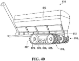
- FIG. 1 shows an example of an off-road tracked vehicle 10 in accordance with an embodiment of the invention.
- the vehicle 10 is a heavy-duty work vehicle for performing agricultural work, construction or other industrial work, or military work. More particularly, in this embodiment, the vehicle 10 is an agricultural vehicle for performing agricultural work. Specifically, in this example, the agricultural vehicle 10 is a tractor. In other examples, the agricultural vehicle 10 may be a combine harvester, another type of harvester, or any other type of agricultural vehicle.
- the agricultural vehicle 10 comprises a frame 12, a powertrain 15, a steering system 17, a plurality of track systems 16 1 , 16 2 (which can be referred to as "undercarriages"), and an operator cabin 20 that enable an operator to move the agricultural vehicle 10 on the ground to perform agricultural work possibly using a work implement 18.
- the track systems 16 1 , 16 2 can be monitored (e.g., during operation of the agricultural vehicle 10) to obtain information about the track systems 16 1 , 16 2 which can be used for various purposes, such as, for example, to convey the information about the track systems 16 1 , 16 2 to a user (e.g., the operator) and/or to control the agricultural vehicle 10, for instance, by controlling a speed of the agricultural vehicle 10 depending on a state (e.g., a temperature and/or one or more other physical characteristics) of one or more of the track systems 16 1 , 16 2 .
- a state e.g., a temperature and/or one or more other physical characteristics
- This may be useful, for example, to gain knowledge about tracks of the track systems 16 1 , 16 2 , to help prevent rapid wear or other deterioration of the tracks of the track systems 16 1 , 16 2 (e.g., blowout), and/or to adapt how fast or slow the agricultural vehicle 10 moves in order to protect the tracks of the track systems 16 1 , 16 2 while permitting the speed of the agricultural vehicle 10 to be greater over short periods (e.g., when travelling on or crossing roads or other particular areas).
- the powertrain 15 is configured for generating motive power and transmitting motive power to the track systems 16 1 , 16 2 to propel the agricultural vehicle 10 on the ground.
- the powertrain 15 comprises a prime mover 14, which is a source of motive power that comprises one or more motors.
- the prime mover 14 comprises an internal combustion engine.
- the prime mover 14 may comprise another type of motor (e.g., an electric motor) or a combination of different types of motor (e.g., an internal combustion engine and an electric motor).
- the prime mover 14 is in a driving relationship with the track systems 16 1 , 16 2 .
- the powertrain 15 transmits motive power generated by the prime mover 14 to one or more of the track systems 16 1 , 16 2 in order to drive (i.e., impart motion to) these one or more of the track systems 16 1 , 16 2 .
- the powertrain 15 may transmit power from the prime mover 14 to the track systems 16 1 , 16 2 in any suitable way.
- the powertrain 15 comprises a transmission 62 between the prime mover 14 and final drive axles 56 1 , 56 1 for transmitting motive power from the prime mover 14 to the track systems 16 1 , 16 2 .
- the transmission 62 may be an automatic transmission (e.g., a continuously variable transmission (CVT)) or any other suitable type of transmission.
- CVT continuously variable transmission
- the work implement 18 is used to perform agricultural work.
- the work implement 18 may be a combine head, a cutter, a scraper, a tiller, or any other type of agricultural work implement.
- the operator cabin 20 is where the operator sits and controls the agricultural vehicle 10. More particularly, the operator cabin 20 comprises a user interface 70 including a set of controls that allow the operator to steer the agricultural vehicle 10 on the ground and operate the work implement 18.
- the user interface 70 comprises an accelerator 72, a brake control 73, and a steering device 74 that are operable by the operator to control motion of the agricultural vehicle 10 on the ground and operation of the work implement 18.
- the user interface 70 also comprises an instrument panel 75 (e.g., a dashboard) which provides indicators (e.g., a speedometer indicator, a tachometer indicator, etc.) to convey information to the operator.
- the track systems 16 1 , 16 2 engage the ground for traction of the agricultural vehicle 10.
- Each track system 16 i comprises a track-engaging assembly 21 and a track 22 disposed around the track-engaging assembly 21.
- the track-engaging assembly 21 comprises a plurality of wheels which, in this example, includes a drive wheel 24 and a plurality of idler wheels that includes a front idler wheel 26 and a plurality of roller wheels 28 1 -28 6 .
- the track system 16 i also comprises a frame 13 which supports various components of the track system 16 i , including the roller wheels 28 1 -28 6 .
- the track system 16 i has a longitudinal direction and a first longitudinal end 57 and a second longitudinal end 59 that define a length of the track system 16 i .
- the track system 16 i has a widthwise direction and a width that is defined by a width of the track 22.
- the track system 16 i also has a height direction that is normal to its longitudinal direction and its widthwise direction.
- the track 22 engages the ground to provide traction to the agricultural vehicle 10.
- a length of the track 22 allows the track 22 to be mounted around the track-engaging assembly 21.
- the track 22 can be referred to as an "endless" track.
- the track 22 comprises an inner side 45, a ground-engaging outer side 47, and lateral edges 49 1 , 49 2 .
- the inner side 45 faces the wheels 24, 26, 28 1 -28 6 , while the ground-engaging outer side 47 engages the ground.
- a top run 65 of the track 22 extends between the longitudinal ends 57, 59 of the track system 16 i and over the wheels 24, 26, 28 1 -28 6
- a bottom run 66 of the track 22 extends between the longitudinal ends 57, 59 of the track system 16 i and under the wheels 24, 26, 28 1 -28 6
- the track 22 has a longitudinal axis 19 which defines a longitudinal direction of the track 22 (i.e., a direction generally parallel to its longitudinal axis) and transversal directions of the track 22 (i.e., directions transverse to its longitudinal axis), including a widthwise direction of the track 22 (i.e., a lateral direction generally perpendicular to its longitudinal axis).
- the track 22 has a thickness direction normal to its longitudinal and widthwise directions.
- the track 22 is elastomeric, i.e., comprises elastomeric material, to be flexible around the track-engaging assembly 21.
- the elastomeric material of the track 22 can include any polymeric material with suitable elasticity.
- the elastomeric material of the track 22 includes rubber.
- Various rubber compounds may be used and, in some cases, different rubber compounds may be present in different areas of the track 22.
- the elastomeric material of the track 22 may include another elastomer in addition to or instead of rubber (e.g., polyurethane elastomer).
- the track 22 comprises an endless body 36 underlying its inner side 45 and ground-engaging outer side 47.
- the body 36 will be referred to as a "carcass".
- the carcass 36 is elastomeric in that it comprises elastomeric material 38 which allows the carcass 36 to elastically change in shape and thus the track 22 to flex as it is in motion around the track-engaging assembly 21.
- the carcass 36 comprises an inner surface 32 and a ground-engaging outer surface 31 that are opposite one another.
- the carcass 36 comprises a plurality of reinforcements embedded in its elastomeric material 38. These reinforcements can take on various forms.
- the carcass 36 comprises a layer of reinforcing cables 37 1 -37 M that are adjacent to one another and extend generally in the longitudinal direction of the track 22 to enhance strength in tension of the track 22 along its longitudinal direction.
- each of the reinforcing cables 37 1 -37 M is a cord including a plurality of strands (e.g., textile fibers or metallic wires).
- each of the reinforcing cables 37 1 -37 M may be another type of cable and may be made of any material suitably flexible along the cable's longitudinal axis (e.g., fibers or wires of metal, plastic or composite material).
- the carcass 36 comprises a layer of reinforcing fabric 43.
- the reinforcing fabric 43 comprises thin pliable material made usually by weaving, felting, knitting, interlacing, or otherwise crossing natural or synthetic elongated fabric elements, such as fibers, filaments, strands and/or others, such that some elongated fabric elements extend transversally to the longitudinal direction of the track 22 to have a reinforcing effect in a transversal direction of the track 22.
- the reinforcing fabric 43 may comprise a ply of reinforcing woven fibers (e.g., nylon fibers or other synthetic fibers).
- the carcass 36 may be molded into shape in a molding process during which the rubber 38 is cured.
- a mold may be used to consolidate layers of rubber providing the rubber 38 of the carcass 36, the reinforcing cables 37 1 -37 M and the layer of reinforcing fabric 43.
- the endless track 22 is a one-piece "jointless” track such that the carcass 36 is a one-piece jointless carcass.
- the endless track 22 may be a "jointed" track (i.e., having at least one joint connecting adjacent parts of the track 22) such that the carcass 36 is a jointed carcass (i.e., which has adjacent parts connected by the at least one joint).
- the track 22 may comprise a plurality of track sections interconnected to one another at a plurality of joints, in which case each of these track sections includes a respective part of the carcass 36.
- the endless track 22 may be a one-piece track that can be closed like a belt with connectors at both of its longitudinal ends to form a joint.
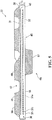
- the inner side 45 of the endless track 22 comprises an inner surface 55 of the carcass 36 and a plurality of wheel-contacting projections 48 1 -48 N that project from the inner surface 55 and are positioned to contact at least some of the wheels 24, 26, 28 1 -28 6 to do at least one of driving (i.e., imparting motion to) the track 22 and guiding the track 22.
- the wheel-contacting projections 48 1 -48 N can be referred to as "wheel-contacting lugs”.
- the wheel-contacting lugs 48 1 -48 N can be referred to as "drive/guide projections" or "drive/guide lugs”.
- a drive/guide lug 48 i may interact with the drive wheel 24 to drive the track 22, in which case the drive/guide lug 48 i is a drive lug.
- a drive/guide lug 48 i may interact with the idler wheel 26 and/or the roller wheels 28 1 -28 6 to guide the track 22 to maintain proper track alignment and prevent de-tracking without being used to drive the track 22, in which case the drive/guide lug 48 i is a guide lug.
- a drive/guide lug 48 i may both (i) interact with the drive wheel 24 to drive the track and (ii) interact with the idler wheel 26 and/or the roller wheels 28 1 -28 6 to guide the track 22 to maintain proper track alignment and prevent de-tracking, in which case the drive/guide lug 48 i is both a drive lug and a guide lug.
- the drive/guide lugs 48 1 -48 N interact with the drive wheel 24 in order to cause the track 22 to be driven, and also interact with the idler wheel 26 and the roller wheels 28 1 -28 6 in order to guide the track 22 as it is driven by the drive wheel 24 to maintain proper track alignment and prevent de-tracking.
- the drive/guide lugs 48 1 -48 N are thus used to both drive the track 22 and guide the track 22 in this embodiment.
- the drive/guide lugs 48 1 -48 N are arranged in a single row disposed longitudinally along the inner side 45 of the track 22.
- the drive/guide lugs 48 1 -48 N may be arranged in other manners in other examples of implementation (e.g., in a plurality of rows that are spaced apart along the widthwise direction of the track 22).
- each drive/guide lug 48 i is an elastomeric drive/guide lug in that it comprises elastomeric material 67.
- the elastomeric material 67 can be any polymeric material with suitable elasticity. More particularly, in this embodiment, the elastomeric material 67 includes rubber. Various rubber compounds may be used and, in some cases, different rubber compounds may be present in different areas of the drive/guide lug 48 i . In other embodiments, the elastomeric material 67 may include another elastomer in addition to or instead of rubber (e.g., polyurethane elastomer).
- the drive/guide lugs 48 1 -48 N may be provided on the inner side 45 in various ways. For example, in this embodiment, the drive/guide lugs 48 1 -48 N are provided on the inner side 45 by being molded with the carcass 36.
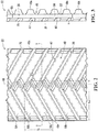
- the ground-engaging outer side 47 comprises a ground-engaging outer surface 75 of the carcass 36 and a tread pattern 40 to enhance traction on the ground.
- the tread pattern 40 comprises a plurality of traction projections 58 1 -58 T projecting from the ground-engaging outer surface 75, spaced apart in the longitudinal direction of the endless track 22 and engaging the ground to enhance traction.
- the traction projections 58 1 -58 T may be referred to as "tread projections" or "traction lugs”.
- the traction lugs 58 1 -58 T may have any suitable shape.
- each of the traction lugs 58 1 -58 T has an elongated shape and is angled, i.e., defines an oblique angle ⁇ (i.e., an angle that is not a right angle or a multiple of a right angle), relative to the longitudinal direction of the track 22.
- the traction lugs 58 1 -58 T may have various other shapes in other examples (e.g., curved shapes, shapes with straight parts and curved parts, etc.).
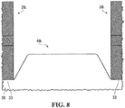
- each traction lug 58 has a periphery 69 which includes a front surface 80 1 , a rear surface 80 2 , two side surfaces 81 1 , 81 2 , and a top surface 86.
- the front surface 80 1 and the rear surface 80 2 are opposed to one another in the longitudinal direction of the track 22.
- the two side faces 81 1 , 81 2 are opposed to one another in the widthwise direction of the track 22.
- the front surface 80 1 , the rear surface 80 2 , and the side surfaces 81 1 , 81 2 are substantially straight.
- the periphery 69 of the traction lug 58 i may have any other shape in other embodiments (e.g., the front surface 80 1 , the rear surface 80 2 , and/or the side surfaces 81 1 , 81 2 may be curved).
- the traction lug 58 i has a front-to-rear dimension L L in the longitudinal direction of the track 22, a side-to-side dimension L W in the widthwise direction of the track 22, and a height H in the thickness direction of the track 22.
- each traction lug 58 i is an elastomeric traction lug in that it comprises elastomeric material 41.
- the elastomeric material 41 can be any polymeric material with suitable elasticity. More particularly, in this embodiment, the elastomeric material 41 includes rubber. Various rubber compounds may be used and, in some cases, different rubber compounds may be present in different areas of the traction lug 58 i . In other embodiments, the elastomeric material 41 may include another elastomer in addition to or instead of rubber (e.g., polyurethane elastomer).
- the traction lugs 58 1 -58 T may be provided on the ground-engaging outer side 27 in various ways. For example, in this embodiment, the traction lugs 58 1 -58 T are provided on the ground-engaging outer side 27 by being molded with the carcass 36.
- the carcass 36 has a thickness T c , measured from its inner surface 32 to its ground-engaging outer surface 31, which is relatively large in this embodiment.
- the thickness T c of the carcass 36 may be at least than 20 mm, in some cases at least 25 mm, in some cases at least 30 mm, in some cases at least 35 mm, and in some cases even more (e.g., 40 mm or more).
- the thickness T c of the carcass 36 may have any other suitable value in other embodiments.
- the track 22 may be constructed in various other manners in other embodiments.
- the track 22 may have recesses or holes that interact with the drive wheel 24 in order to cause the track 22 to be driven (e.g., in which case the drive/guide lugs 48 1 -48 N may be used only to guide the track 22 without being used to drive the track 22, i.e., they may be "guide lugs" only), and/or the ground-engaging outer side 47 of the track 22 may comprise various patterns of traction lugs.
- the drive wheel 24 is rotatable by power derived from the prime mover 14 to drive the track 22. That is, power generated by the prime mover 14 and delivered over the powertrain 15 of the agricultural vehicle 10 can rotate a final drive axle 56 i , which causes rotation of the drive wheel 24, which in turn imparts motion to the track 22.
- the drive wheel 24 comprises a drive sprocket comprising a plurality of drive members 52 1 -52 B spaced apart along a circular path to engage the drive/guide lugs 48 1 -48 N of the track 22 in order to drive the track 22.
- the drive wheel 24 and the track 22 thus implement a "positive drive” arrangement.
- the drive wheel 24 comprises two side discs 50 1 , 50 2 which are co-centric and turn about a common axle 51 and between which the drive members 52 1 -52 B extend near respective peripheries of the side discs 50 1 , 50 2 .
- the drive members 52 1 -52 B are thus drive bars that extend between the side discs 50 1 , 50 2 .
- the drive wheel 24 and the track 22 have respective dimensions allowing interlocking of the drive bars 52 1 -52 B of the drive wheel 24 and the drive/guide lugs 48 1 -48 N of the track 22.
- Adjacent ones of the drive bars 52 1 -52 B define an interior space 53 between them to receive one of the drive/guide lugs 48 1 -48 N .
- Adjacent ones of the drive/guide lugs 48 1 -48 N define an inter-lug space 39 between them to receive one of the drive bars 52 1 -52 B .
- the drive/guide lugs 48 1 -48 N and the drive bars 52 1 -52 B have a regular spacing that allows interlocking of the drive/guide lugs 48 1 -48 N and the drive bars 52 1 -52 B over a certain length of the drive wheel's circumference.
- the drive wheel 24 may be configured in various other ways in other embodiments.
- the drive wheel 24 may not have any side discs such as the side discs 50 1 , 50 2 .
- the drive members 52 1 -52 B may be drive teeth that are distributed circumferentially along the drive wheel 24 or any other type of drive members.
- the drive wheel 24 may have teeth that enter these recesses or holes in order to drive the track 22.
- the drive wheel 24 may frictionally engage the inner side 45 of the track 22 in order to frictionally drive the track 22 (i.e., the drive wheel 24 and the track 22 may implement a "friction drive" arrangement).
- the front idler wheel 26 and the roller wheels 28 1 -28 6 are not driven by power supplied by the prime mover 14, but are rather used to do at least one of supporting part of the weight of the agricultural vehicle 10 on the ground via the track 22, guiding the track 22 as it is driven by the drive wheel 24, and tensioning the track 22. More particularly, in this embodiment, the front idler wheel 26 is a leading idler wheel which maintains the track 22 in tension and helps to support part of the weight of the agricultural vehicle 10 on the ground via the track 22.
- the roller wheels 28 1 -28 6 roll on a rolling path 33 of the inner side 45 of the track 22 along the bottom run 66 of the track 22 to apply the bottom run 66 on the ground. In this case, as they are located between frontmost and rearmost ones of the wheels of the track system 16 i , the roller wheels 28 1 -28 6 can be referred to as "mid-rollers".
- the agricultural vehicle 10 comprises a monitoring system 82 for monitoring the track systems 16 1 , 16 2 to obtain information about the track systems 16 1 , 16 2 which can be used for various purposes, such as, for example, to communicate the information about the track systems 16 1 , 16 2 to a user (e.g., the operator) and/or to control the agricultural vehicle 10 based on a state (e.g., a temperature and/or one or more other physical characteristics) of one or more of the track systems 16 1 , 16 2 .
- a monitoring system 82 for monitoring the track systems 16 1 , 16 2 to obtain information about the track systems 16 1 , 16 2 which can be used for various purposes, such as, for example, to communicate the information about the track systems 16 1 , 16 2 to a user (e.g., the operator) and/or to control the agricultural vehicle 10 based on a state (e.g., a temperature and/or one or more other physical characteristics) of one or more of the track systems 16 1 , 16 2 .
- a state
- This may be useful, for example, to gain knowledge about the tracks 22 of the track systems 16 1 , 16 2 , to help prevent rapid wear or other deterioration of the tracks 22 (e.g., blowout of one or more of the traction lugs 58 1 -58 T ), and/or to adapt the speed of the agricultural vehicle 10 in order to protect the tracks 22 while permitting the agricultural vehicle 10 to travel faster for short periods (e.g., when travelling on or crossing roads or other particular areas).
- the monitoring system 82 comprises a plurality of sensors 84 1 -84 s for monitoring each track system 16 i and a processing entity 88 for performing certain actions based on input from the sensors 84 1 -84 s .
- actions performed by the processing entity 88 based on input from the sensors 84 1 -84 s may include an action to convey information about the track system 16 i , an action to store information about the track system 16 i , and/or an action relating to the operation of the agricultural vehicle 10, such as, for example, controlling the speed and/or another operational aspect of the agricultural vehicle 10 and/or providing information to the operator of the agricultural vehicle 10.
- Each sensor 84 x is configured to sense a physical characteristic of the track system 16 i and to issue a sensor signal relating to the track system 16 i and derived based on the physical characteristic of the track system 16 i that is sensed.
- the physical characteristic of the track system 16 i that is sensed by the sensor 84 x is a temperature of the track system 16 i .
- the sensor 84 x is thus a temperature sensor. More particularly, in this embodiment, the temperature of the track system 16 i that is sensed by the temperature sensor 84 x is a temperature of the track 22.
- the sensor signal issued by the sensor 84 x is thus indicative of the temperature of the track 22.
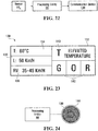
- Monitoring of the temperature of the track 22 may be used by the processing entity 88 to perform certain actions, such as to convey the temperature of the track 22 to a user (e.g., the operator), to store the temperature of the track 22 in memory (e.g., for future consultation), to limit and/or reduce the speed of the agricultural vehicle 10 and/or notify the operator of the agricultural vehicle 10 if the temperature of the track 22 becomes high enough (e.g., in order to prevent blowout or other accelerated wear of the track 22), and/or to allow the speed of the agricultural vehicle 10 to be increased if the temperature of the track 22 drops or remains low enough.
- a user e.g., the operator
- memory e.g., for future consultation
- the temperature sensor 84 x comprises a sensing device 85 to sense the temperature of the track 22.
- the sensing device 85 may be implemented in any suitable way.
- the sensing device 85 may comprise a thermocouple, a thermistor, a resistance temperature detector, an infrared sensor, or any other type of sensing device capable of sensing temperature.
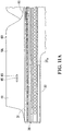
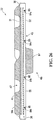
- the temperature sensor 84 x is part of the track 22. More specifically, in this embodiment, the temperature sensor 84 x is embedded within the elastomeric material of the track 22. This may allow the temperature to be measured inside the track 22 where it is likely to be greater than on a periphery of the track 22. For instance, the temperature sensor 84 x may be located to sense the temperature at a high heat area within the track 22, such as at or near a hottest area within the track 22, which is an area expected to be hottest in use.
- the temperature sensor 84 x is disposed within the elastomeric material 41 of a traction lug 58 i . This allows sensing the temperature at an internal (e.g., an inmost) area of the traction lug 58 i which is susceptible to generating high heat that could lead to blowout of the traction lug 58 i .
- respective ones of the temperature sensors 84 1- 84 s are disposed in the elastomeric material 41 of respective ones of the traction lugs 58 1 -58 T .
- the temperature of the track 22 may be assessed by the processing entity 88 based on temperature readings at one or more of the respective ones of the traction lugs 58 1 -58 T (e.g., the temperature of the track 22 may be deemed to be a maximal one or an average of the temperature readings at one or more of the respective ones of the traction lugs 58 1 -58 T ).
- it is possible to have a sensor 84 x within each traction lug 58 i this may not be the case in some embodiments.
- data collected by three or four of the sensors 84 1 -84 s provided within respective ones of the traction lugs 58 1 -58 T may enable assessment of the temperature of the track 22.
- the track 22 may include only a single temperature sensor 84 x (e.g., in only a single one of the traction lugs 58 1 -58 T ).
- the sensing device 85 of the temperature sensor 84 x may be located at a hottest point 95 of a traction lug 58 i to measure the temperature at that hottest point 95.
- the hottest point 95 of the traction lug 58 i may be an inmost point of the traction lug 58 i that is farthest away from the periphery 69 of the traction lug 58 i (e.g., at half the height H and half the side-to-side dimension L W of the traction lug 58 i ).
- the sensing device 85 of the temperature sensor 84 x may be located at a reference point 97 spaced apart from the hottest point 95 of the traction lug 58 i to measure the temperature at that reference point 97.
- the temperature at the reference point 97 of the traction lug 58 i is correlated to the temperature at the hottest point 95 of the traction lug 58 i based on a temperature model for the traction lug 58 i .
- the temperature model may define a temperature difference between the hottest point 95 and the reference point 97.
- the temperature model may use one or more inputs (besides the temperature at the reference point 97) to obtain the temperature at the hottest point 95 based on the temperature at the reference point 97.
- This may include, for example, a spacing S P between the reference point 97 and the hottest point 95 of the traction lug 58 i , material properties (e.g., thermal conductivity) of elastomeric material of the track 22 (e.g., the elastomeric material 41 of the traction lug 58 i , the elastomeric material 38 of the carcass 36), design parameters of the traction lug 58 i (e.g., dimensions such as height, width and length, heat transfer coefficient, etc.), environmental conditions (e.g., ambient temperature), a condition of the traction lug 58 i (e.g., a wear condition of the traction lug 58 i ).
- material properties e.g., thermal conductivity
- design parameters of the traction lug 58 i e.g., dimensions such as height, width and length, heat transfer coefficient, etc.
- environmental conditions e.g., ambient temperature
- a condition of the traction lug 58 i
- the temperature model may use these one or more inputs to determine the temperature at the hottest point 95. For instance, in a specific example of implementation, the temperature model may associate a given value of the spacing S P between the reference point 97 and the hottest point 95 with a particular temperature difference between the hottest point 95 and the reference point 97 such that the temperature model can obtain the temperature at the hottest point 95 by adding the temperature difference to the temperature at the reference point 97.
- the temperature model may be implemented in various ways. For instance, in some embodiments, the temperature model may be established by calibrating the temperature sensor 84 x accordingly. That is, the temperature model may be established by causing the temperature sensor 84 x to record a temperature reading that corresponds substantially to the temperature at the hottest point 95. For instance, according to a simplified example, if it has been observed that a given spacing S P between the reference point 97 and the hottest point 95 results in a given temperature difference between the hottest point 95 and the reference point 97, then the temperature sensor 84 x , which is located at the reference point 97, may be calibrated such as to offset its temperature readings by the given temperature difference between the hottest point 95 and the reference point 97.
- the temperature sensor 84 x could be calibrated to record a temperature of 20°C higher than the temperature at the reference point 97 (i.e., record a temperature 20°C higher than what the temperature at the reference point 97 is in reality).
- the calibration of the temperature sensor 84 x may be more complex than a "fixed" offset of the temperature recorded by the temperature sensor 84 x (i.e., a constant offset).
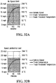
- the calibration of the temperature sensor 84 x may be implemented via a calibration curve (e.g., a function) which serves to calibrate (i.e., compensate) the temperature recorded at the reference point 97 by the temperature sensor 84 x .
- the calibration curve implemented by the temperature sensor 84 x may be a result of testing and plotting of various heating cycles experienced by the temperature sensor 84 x while it is located at the reference point 97 compared to an actual temperature recorded at the hottest point 95.
- the calibration curve may take into account one or more factors such as those listed above (e.g., the spacing S P between the hottest point 95 and the reference point 97, material properties of elastomeric material of the track 22, design parameters of the traction lug 58 i )
- the temperature model may be established at the processing entity 88 of the monitoring system 82.
- the temperature model may be implemented as a function that is executed at the processing entity 88.
- the function implemented by the temperature model may be any type of function having as a variable one or more of the inputs listed above (e.g., the spacing Sp between the hottest point 95 and the reference point 97, the material properties of elastomeric material of the track 22, design parameters of the traction projection 58 i , environmental conditions).
- the factor of proportionality A may be determined by any of a number of inputs such as those discussed above, including the spacing S P between the hottest point 95 and the reference point 97, the material properties of the elastomeric material of the track 22 (e.g., elastomeric material 41 of the traction projection 58 i and/or the elastomeric material 38 of the carcass 36), design parameters of the traction projection 58 i and/or environmental conditions (e.g., ambient temperature).
- the material properties of the elastomeric material of the track 22 e.g., elastomeric material 41 of the traction projection 58 i and/or the elastomeric material 38 of the carcass 36
- design parameters of the traction projection 58 i and/or environmental conditions e.g., ambient temperature
- the spacing Sp may be significant.
- a ratio of the spacing Sp over the height H of the traction lug 58 i may be at least 0.3, in some cases at least 0.4, in some cases at least 0.5, in some cases at least 0.6, in some cases at least 0.7, and in some cases even more.
- the spacing S P may not be as significant.
- the ratio of the spacing S P over the height H of the traction lug 58 i may be no more than 0.3, in some cases no more than 0.2, in some cases no more than 0.1, and in some cases even less.
- the temperature sensor 84 x may be provided and retained within the elastomeric material 41 of the traction lug 58 i in various ways. For instance, in this embodiment, the temperature sensor 84 x is placed in a mold used for molding of the track 22 (including the carcass 36, the drive/guide lugs 48 1 -48 N and the traction lugs 58 1 -58 T ) and the elastomeric material 41 is molded over the temperature sensor 84 x .
- this may involve disposing a first layer of elastomeric material (e.g., destined to form part of the elastomeric material 38 of the carcass 36 or the elastomeric material 41 of the traction lugs 58 1 -58 T ) within a mold, positioning the sensor 84 x on the first layer of elastomeric material, and disposing a second layer of elastomeric material (e.g., destined to form part of the elastomeric material 41 of the traction lugs 58 1 -58 T ) on top of the first layer of elastomeric material such as to effectively sandwich the sensor 84 x between the first and second layers of elastomeric material.
- a first layer of elastomeric material e.g., destined to form part of the elastomeric material 38 of the carcass 36 or the elastomeric material 41 of the traction lugs 58 1 -58 T
- a second layer of elastomeric material e
- an adhesive may be used to help retention of the sensor 84 x in elastomeric material (e.g., in the elastomeric material 41 of the traction projection 58 i and/or in the elastomeric material 38 of the carcass 36).
- the adhesive may be a metal-to-elastomer adhesive such as ChemlokTM or any other suitable metal-to-elastomer adhesive.
- the temperature sensor 84 x may be inserted into the elastomeric material 41 of the traction lug 58 i after molding of the elastomeric material 41 of the traction lug 58 i .
- the traction lug 58 i may be opened (e.g., via drilling a hole or making an incision) and the temperature sensor 84 x inserted into the elastomeric material 41 of the traction lug 58 i .
- the traction lug 58 i may be sealed thereafter.
- the temperature sensor 84 x may be retained in the traction lug 58 i by overmolding (i.e., molding a layer of elastomeric material on top of an already molded layer of elastomeric material), by friction (e.g., a press-fit), by an adhesive, or by a fastener.
- overmolding i.e., molding a layer of elastomeric material on top of an already molded layer of elastomeric material
- friction e.g., a press-fit
- an adhesive e.g., a fastener
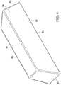
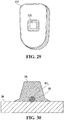
- the temperature sensor 84 x is enclosed within a housing 96.
- the housing 96 is configured to protect the temperature sensor 84 x by preventing the intrusion of particles that may be damaging to the temperature sensor 84 x .
- the housing 96 may be rated IP67 or IP68 according to the IP Code which classifies and rates the degree of protection provided against intrusion, dust, accidental contact, and water by mechanical casings and electrical enclosures.
- the housing 96 comprises two halves which are secured to one another via fasteners 98, and an opening 100 for allowing the sensing device 85 of the temperature sensor 84 x to make a temperature reading.
- a periphery of the opening 100 may be provided with a sealing element for preventing the intrusion of particles into the housing 96.
- the housing 96 may be configured differently in other embodiments.
- the housing 96 comprises a material 89 which imparts strength and protective qualities to the housing 96.
- the protective material 89 may be a heat resistant material such that the housing 96 is not damaged when subjected to high heat.
- the protective material 89 imparts sufficient strength to the housing 96 for the housing 96 to withstand deformation of the elastomeric material 41 surrounding it.
- the protective material 89 comprises a thermoplastic polymer (e.g., acrylonitrile butadiene styrene (ABS) or a polycarbonate).
- ABS acrylonitrile butadiene styrene
- the protective material 89 may comprise any other suitable material in other embodiments.
- the temperature sensor 84 x comprises an interface 105 comprising a transmitter 90 for issuing the sensor signal indicative of the temperature of the track 22.
- the transmitter 90 is configured for transmitting the sensor signal indicative of the temperature of the track 22 to the processing entity 88, which comprises a receiver 104 to receive the sensor signal from the temperature sensor 84.
- the transmitter 90 of the temperature sensor 84 x and the receiver 104 of the processing entity 88 may be connected in any suitable way.
- the temperature sensor 84 x and the processing entity 88 are connected wirelessly.
- the transmitter 90 of the temperature sensor 84 x is a wireless transmitter that can wirelessly transmit the sensor signal
- the receiver 104 of the processing entity 88 is a wireless receiver that can wirelessly receive the sensor signal.
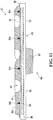
- the sensor 84 x may be disposed such that the sensor signal issued by the sensor 84 x has a signal strength sufficient to overcome a thickness of elastomeric material of the track 22 along a path of the sensor signal. More particularly, in this embodiment, the transmitter 90 of the sensor 84 x is spaced from the sensing device 85 of the sensor 84 x and located beneath less elastomeric material than the sensing device 85.
- a thickness T E1 of elastomeric material of the track 22 between the transmitter 90 and the periphery 69 of the traction lug 58 i is less than a thickness T E2 of elastomeric material of the track 22 between the sensing device 85 and the periphery 69 of the traction lug 58 i .
- a ratio T E1 /T E2 of the thickness T E1 of elastomeric material of the track 22 between the transmitter 90 and the periphery 69 of the traction lug 58 i over the thickness T E2 of elastomeric material of the track 22 between the sensing device 85 and the periphery 69 of the traction lug 58 i may be no more than 0.5, in some cases no more than 0.4, in some cases no more than 0.3, in some cases no more than 0.2, in some cases no more than 0.1, and in some cases even less.
- This ratio may have any other suitable value in other embodiments.
- a thickness of elastomeric material of the track 22 between the transmitter 90 and the ground-engaging outer surface 31 of the carcass 36 may be less than the thickness T E2 of elastomeric material of the track 22 between the sensing device 85 and the periphery 69 of the traction lug 58 i .
- a ratio of the thickness of elastomeric material of the track 22 between the transmitter 90 and the ground-engaging outer surface 31 of the carcass 36 over the thickness T E2 of elastomeric material of the track 22 between the sensing device 85 and the periphery 69 of the traction lug 58 i may be no more than 0.4, in some cases no more than 0.3, in some cases no more than 0.2, in some cases no more than 0.1, and in some cases even less.
- This ratio may have any other suitable value in other embodiments.
- the transmitter 90 may be positioned such that the traction lug 58 i does not overlap the transmitter 90 (i.e., such that the transmitter 90 has a different longitudinal and widthwise position in the track 22 than the traction lug 58 i ).
- the sensor signal indicative of the temperature of the track 22 may be issued by the temperature sensor 84 x in any suitable manner.
- the processing entity 88 is configured to issue an interrogation signal directed to the temperature sensor 84 x , which is configured to issue the sensor signal indicative of the temperature of the track 22 to the processing entity 88 in response to the interrogation signal.
- the processing entity 88 comprises a transmitter 106 to transmit the interrogation signal to the temperature sensor 84 x , the interface 105 of which comprises a receiver 92 to receive the interrogation signal.
- the transmitter 106 of the processing entity 88 is a wireless transmitter to wirelessly transmit the interrogation signal and the receiver 92 of the interface 105 of temperature sensor 84 x is a wireless receiver to wirelessly receive the interrogation signal.
- the transmitter 90 and the receiver 92 of the temperature sensor 84 x may be implemented by a transceiver and/or the transmitter 106 and the receiver 104 of the processing entity 88 may be implemented by a transceiver.
- the temperature sensor 84 x and the processing entity 88 implement radio-frequency identification (RFID) technology to communicate, including to wirelessly transmit the sensor signal indicative of the temperature of the track 22 from the temperature sensor 84 x to the processing entity 88.
- RFID radio-frequency identification
- the transmitter 90 and the receiver 92 of the temperature sensor 84 x implement an RFID element (e.g., an RFID tag) and the transmitter 106 and the receiver 104 of the processing entity 88 implement an RFID element (e.g., an RFID reader).
- the RFID element implemented by the transmitter 90 and the receiver 92 of the temperature sensor 84 x may be a passive RFID tag that is powered by the interrogation signal of the RFID element implemented by the transmitter 106 and the receiver 104 of the processing entity 88, which may be an active RFID reader. That is, the RFID tag implemented by the transmitter 90 and the receiver 92 of the temperature sensor 84 x is electromagnetically powered by the interrogation signal of the RFID reader implemented by the transmitter 106 and the receiver 104 of the processing entity 88. The power generated through this interaction may then be used by the RFID tag to issue the sensor signal indicative of the temperature of the track 22.
- the RFID tag implemented by the transmitter 90 and the receiver 92 of the temperature sensor 84 x enables the sensing device 85 of the temperature sensor 84 x to record a temperature reading. More specifically, when the RFID tag is powered by the interrogation signal of the RFID reader, at least part of the power is routed to the sensing device 85 in order for the sensing device 85 to record a temperature reading. The transmitter 90 then issues the sensor signal indicative of the temperature of the track 22 (as recorded by the sensing device 85) to the RFID reader implemented by the transmitter 106 and the receiver 104 of the processing entity 88.
- the RFID tag implemented by the transmitter 90 and the receiver 92 of the temperature sensor 84 x and the RFID reader implemented by the transmitter 106 and the receiver 104 of the processing entity 88 may be off-the-shelf components.
- an RFID tag integrating a sensing device 85 for recording temperature readings is manufactured by Farsens (e.g., the Fenix passive RFID sensor tag). Such RFID tags are compatible with commonly available RFID readers.
- the temperature sensor 84 x may be configured to issue the input signal indicative of the temperature of the track 22 to the processing entity 88 autonomously (i.e., without receiving any interrogation signal). For instance, in some embodiments, the transmitter 94 of the temperature sensor 84 x may issue the input signal indicative of the temperature of the track 22 to the processing entity 88 repeatedly (e.g., periodically or at some other predetermined instants).
- the RFID element implemented by the transmitter 90 and the receiver 92 of the temperature sensor 84 x may be an active RFID tag or a battery-assisted passive (BAP) RFID tag.
- an active RFID tag implemented by the transmitter 90 and the receiver 92 of the temperature sensor 84 x has its own power source (e.g., a battery) to enable the entire functionality of the active RFID tag. That is, the active RFID tag's power source enables the sensing device 85 to record a temperature reading and also enables the transmitter 94 to issue the input signal indicative of the temperature of the track 22 to the RFID reader (i.e., the processing entity 88).
- the active RFID tag can implement its functions independently of the RFID reader.
- the power source (i.e., the battery) of the active RFID tag may be configured to provide power to the RFID tag for an amount of time at least as great, and in some cases greater, than a lifetime of the track 22 (i.e., a span of time that the track 22 is expected to last).
- the battery of the active RFID tag may have a 10-year battery life which may be sufficient to outlast the lifetime of the track 22 which, under moderate use, may be approximately 3 to 5 years, for example.
- a BAP RFID tag's power source e.g., a battery
- the power source may enable the sensing device 85 to record a temperature reading.
- the BAP RFID tag is dependent on the interrogation signal of the RFID reader (i.e., the processing entity 88) to power the transmitter 94 to issue the input signal indicative of the temperature of the track 22 to the processing entity 88.
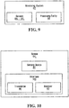
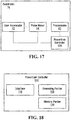
- the processing entity 88 is configured to perform one or more actions based on the sensor signal from the sensor 84 x and possibly other input and/or information. For example, in some embodiments, the processing entity 88 may issue an output signal relating to the operation of the agricultural vehicle 10 derived from the sensor signal from the sensor 84 x . For instance, in some embodiments, as shown in Figure 27 , the output signal issued by the processing entity 88 may be directed to the powertrain 15 of the agricultural vehicle 10 to control the operation of the agricultural vehicle 10 based on the temperature of the track 22. In other embodiments, the output signal issued by the processing entity 88 may be directed to a communication device (e.g., comprising a display) for outputting information regarding the operation of the agricultural vehicle 10 to the operator of the agricultural vehicle 10.
- a communication device e.g., comprising a display
- the processing entity 88 may issue an output signal conveying information about the track system 16 i , such as the temperature of the track 22.
- the processing entity 88 may store information about the track system 16 i in memory (e.g., for future reference), such as the temperature of the track 22 at a given moment (e.g., date and time).
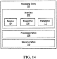
- the processing entity 88 comprises an interface 102, a processing portion 108, and a memory portion 110, which are implemented by suitable hardware and/or software.
- the interface 102 comprises one or more inputs and outputs allowing the processing entity 88 to receive input signals from and send output signals to other components to which the processing entity 88 is connected (i.e., directly or indirectly connected).
- an input of the interface 102 is implemented by the wireless receiver 104 to receive the sensor signal from the temperature sensor 84 x .
- An output of the interface 102 is implemented by a transmitter 112 to transmit the output signal relating to the operation of the agricultural vehicle 10.
- another output of the interface 102 is implemented by the wireless transmitter 106 to transmit the interrogation signal to the temperature sensor 84 x .
- the processing portion 108 comprises one or more processors for performing processing operations that implement functionality of the processing entity 88.
- a processor of the processing portion 108 may be a general-purpose processor executing program code stored in the memory portion 110.
- a processor of the processing portion 108 may be a specific-purpose processor comprising one or more preprogrammed hardware or firmware elements (e.g., application-specific integrated circuits (ASICs), electrically erasable programmable read-only memories (EEPROMs), etc.) or other related elements.
- ASICs application-specific integrated circuits
- EEPROMs electrically erasable programmable read-only memories
- the memory portion 110 comprises one or more memories for storing program code executed by the processing portion 108 and/or data used during operation of the processing portion 108.
- a memory of the memory portion 110 may be a semiconductor medium (including, e.g., a solid-state memory), a magnetic storage medium, an optical storage medium, and/or any other suitable type of memory.
- a memory of the memory portion 110 may be read-only memory (ROM) and/or random-access memory (RAM), for example.
- two or more elements of the processing entity 88 may be implemented by devices that are physically distinct from one another and may be connected to one another via a bus (e.g., one or more electrical conductors or any other suitable bus) or via a communication link which may be wired, wireless, or both. In other embodiments, two or more elements of the processing entity 88 may be implemented by a single integrated device.
- a bus e.g., one or more electrical conductors or any other suitable bus
- a communication link which may be wired, wireless, or both.
- two or more elements of the processing entity 88 may be implemented by a single integrated device.
- the processing entity 88 may be implemented in any other suitable way in other embodiments.
- At least part of the temperature sensor 84 x and/or at least part of the processing entity 88 may be disposed relative to one another and/or the track 22 so as to facilitate communication between them.
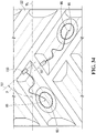
- At least part of the temperature sensor 84 x and/or at least part of the processing entity 88 may be oriented so as to provide more time for them to communicate with one another as the track 22 moves around the track-engaging assembly 21 and/or to reduce or minimize potential interference with one or more components of the track system 16 i (e.g., metallic components such as the reinforcing cables 37 1 -37 M or a layer of fabric 43 of the track 22).
- an orientation of the interface 105 of the temperature sensor 84 x and/or an orientation of the interface 102 of the processing entity 88 may be arranged as such. That is, the interface 105 of the temperature sensor 84 x and/or the interface 102 of the processing entity 88 may be oriented to not be in alignment with reinforcing cables 37 1 -37 M and/or fabric elements of a layer of fabric 43.
- a portion 150 of the temperature sensor 84 x that comprises the interface 105 of the temperature sensor 84 x may have a longitudinal axis 151 that is oriented transversally to the widthwise direction of the track 22 and/or transversally to the longitudinal direction of the track 22 and/or a portion 152 of the processing entity 88 that comprises the interface 102 of the processing entity 88 (e.g., an antenna such as an RFID antenna) may have a longitudinal axis 153 that is oriented transversally to the widthwise direction of the track 22 and/or transversally to the longitudinal direction of the track 22.
- an angle ⁇ between the longitudinal axis 151 of the portion 150 of the temperature sensor 84 x and an axis W A extending along the widthwise direction of the track 22 may be at least 15°, in some cases at least 30°, in some cases at least 45°, and in some cases even more.
- an angle ⁇ between the longitudinal axis 153 of the portion 152 of the processing entity 88 and the axis W A extending along the widthwise direction of the track 22 may be at least 15°, in some cases at least 30°, in some cases at least 45°, and in some cases even more.
- the longitudinal axis 151 of the portion 150 of the temperature sensor 84 x may be parallel to the longitudinal axis 153 of the portion 152 of the processing entity 88.
- the output signal relating to the operation of the agricultural vehicle 10 that may be issued by the processing entity 88 in some embodiments may be used in various ways.
- the output signal issued by the processing entity 88 may be directed to the powertrain 15 of the agricultural vehicle 10 to control the operation of the vehicle based on the temperature of the track 22.
- the output signal issued by the processing entity 88 may be directed to the powertrain 15 of the agricultural vehicle 10 to control the speed of the agricultural vehicle 10, such as by limiting and/or reducing the speed of the vehicle 10 or by allowing the speed of the vehicle 10 to be increased, based on the temperature of the track 22.
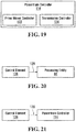
- the output signal issued by the processing entity 88 may be directed to a powertrain controller 114 of the powertrain 15.
- the powertrain controller 114 is configured for controlling operation of the powertrain 15.
- the powertrain controller 114 is an electronic controller that comprises suitable hardware and/or software (e.g., firmware) configured to implement its functionality.
- the powertrain controller 114 comprises an interface 116, a processing portion 118 and a memory portion 120.
- the interface 116 allows the powertrain controller 114 to receive inputs from and release outputs to other components of the agricultural vehicle 10 to which the powertrain controller 114 is connected (i.e., directly or indirectly connected to), including, in this embodiment, the prime mover 14, the transmission 62, the accelerator 72 and/or other components of the user interface 70, and one or more sensors (e.g., a throttle position sensor; a prime mover speed sensor, i.e., a sensor sensing a speed of the prime mover 14; a vehicle speed sensor, i.e., a sensor sensing a speed of the agricultural vehicle 10 on the ground; a prime mover temperature sensor; an outside environment temperature sensor; etc.).
- the interface 116 of the powertrain controller 114 allows the powertrain controller 114 to receive the output signal of the processing entity 88.
- the processing portion 118 comprises one or more processors for performing processing operations that implement functionality of the powertrain controller 114.
- a processor of the processing portion 118 may be a general-purpose processor executing program code stored in the memory portion 120.
- a processor of the processing portion 118 may be a specific-purpose processor comprising one or more preprogrammed hardware or firmware elements (e.g., application-specific integrated circuits (ASICs), electrically erasable programmable read-only memories (EEPROMs), etc.) or other related elements.
- ASICs application-specific integrated circuits
- EEPROMs electrically erasable programmable read-only memories
- the memory portion 120 comprises one or more memories for storing program code executed by the processing portion 118 and/or data used during operation of the processing portion 118.
- a memory of the memory portion 120 may be a semiconductor memory (e.g., read-only memory (ROM) and/or random-access memory (RAM)), a magnetic storage medium, an optical storage medium, and/or any other suitable type of memory.
- ROM read-only memory
- RAM random-access memory
- the powertrain controller 114 comprises a prime mover controller 122 and a transmission controller 124.
- the prime mover controller 122 may be an engine control unit (ECU) and the transmission controller 124 may be a transmission control unit (TCU).
- ECU engine control unit
- TCU transmission control unit
- the powertrain controller 114 may be a distributed controller in which the prime mover controller 122 and the transmission controller 124 are physically distinct from one another and may be connected to one another via a bus (e.g., a controller-area network (CAN) bus or other suitable bus).
- the prime mover controller 122 and the transmission controller 124 may be functional entities of a single physical control module (e.g., a powertrain control module (PCM)).
- PCM powertrain control module
- the prime mover controller 122 is configured to control operation of the prime mover 14. Specifically, the prime mover controller 122 is configured to control one or more prime mover characteristics.
- one prime mover characteristic controlled by the prime mover controller 122 is a power output of the prime mover 14.
- the power output of the prime mover 14 refers to the power currently generated by the prime mover 14. It can be evaluated as a torque produced by the prime mover 14 multiplied by a speed (i.e., a rotational speed) of the prime mover 14 (e.g., revolutions per minute (RPM)) at a given instant.
- a speed i.e., a rotational speed
- RPM revolutions per minute
- the prime mover controller 122 controls the power output of the prime mover 14 based on inputs from various entities, such as: the accelerator 72 and/or one or more other components of the user interface 70; one or more sensors (e.g., a throttle position sensor, an air-fuel ratio sensor, a prime mover speed sensor, a vehicle speed sensor, a temperature sensor, a pressure sensor, etc.); one or more other controllers (e.g., the transmission controller 124); and/or other entities.
- the prime mover controller 122 may control the power output of the prime mover 14 based on the output signal issued by the processing entity 88.
- the prime mover controller 122 comprises a program stored in the memory portion 120 and executed by the processing portion 118.
- the program may determine the power output of the prime mover 14 by performing computations based on inputs from a throttle position sensor, an air-fuel ratio sensor, a prime mover speed sensor, the accelerator 72, and/or the transmission controller 124.
- the program may determine the power output of the prime mover 14 based on the output signal issued by the processing entity 88.
- certain operations of the program may refer to reference data stored in the memory portion 120.
- This reference data comprises data representative of one or more maps, tables, curves or other sets of reference values that are used during execution of the program of the prime mover controller 122.
- the reference data may associate different values of certain parameters of the prime mover 14 (e.g., the speed, temperature, air-fuel ratio, pressure, etc. of the prime mover 14) to corresponding values of fuel injection, ignition timing, valve timing, and/or other parameters of the prime mover 14 (e.g., a fuel map, an injection map, a boost map, and/or other performance map).
- Such programs and reference data are well-understood by those skilled in the art and will therefore not be discussed in further detail.
- the transmission controller 124 is configured to control operation of the transmission 62. Specifically, the transmission controller 124 is configured to control one or more transmission characteristics. For example, in this embodiment, the transmission controller 124 controls a transmission state of the transmission 62.
- the transmission state of the transmission 62 can be defined in terms of (i) a transmission ratio of the transmission 62, which is the ratio that the transmission 62 currently applies between its input and its output, and/or (ii) an output direction of the transmission 62, which refers to a direction of motion (i.e., forward or reverse) of the output of the transmission 62 that allows the agricultural vehicle 10 to advance or back up.
- the transmission state of the transmission 62 is one of a set of available transmission states.
- the set of available transmission states can comprise a number of available transmission ratios that can be applied by the transmission 62. This number may be a finite number (e.g., two, three, four or any other finite number) of available transmission ratios, or an infinite number of available transmission ratios (e.g., in embodiments where the transmission 20 comprises a CVT).
- the transmission controller 124 controls the transmission state of the transmission 62 based on inputs from various entities, such as: the accelerator 72 and/or one or more other components (e.g., a gear shift stick or pedal) of the user interface 70; one or more sensors (e.g., a throttle position sensor, a shift lever sensor, a prime mover speed sensor, a vehicle speed sensor, a temperature sensor, etc.); one or more other controllers (e.g., the prime mover controller 122); and/or other entities.
- the transmission controller 124 may control the transmission state of the transmission 62 based on the output signal issued by the processing entity 88.
- the transmission controller 124 comprises a program stored in the memory portion 120 and executed by the processing portion 118.
- the program may determine when and how to shift between different transmission ratios of the transmission 62 by performing certain computations based on inputs from a throttle position sensor, a prime mover speed sensor, a vehicle speed sensor, the accelerator 72 and/or other components of the user interface 70, and/or the prime mover controller 122.
- the program may determine the power output of the prime mover 14 based on the output signal issued by the processing entity 88.
- certain operations of the program may refer to reference data stored in the memory portion 120.
- This reference data comprises data representative of one or more maps, tables, curves or other sets of reference values that are used during execution of the program of the transmission controller 124.
- the reference data may associate different values of the speed of the prime mover 14 and of the speed of the agricultural vehicle 10 to corresponding transmission ratios of the transmission 62.
- Such programs are well-understood by those skilled in the art and will therefore not be discussed in further detail.
- the powertrain controller 114 controls the speed of the agricultural vehicle 10 at least in part based on the temperature of the track 22. That is, the powertrain controller 114 controls the speed of the agricultural vehicle 10 at least in part based on the output signal issued by the processing entity 88 to the powertrain controller 114.
- the powertrain controller 114 is operable to limit the speed of the agricultural vehicle 10 at least in part based on the temperature of the track 22. For instance, in response to the output signal issued by the processing entity 88, the powertrain controller 114 may control the prime mover 14 and/or the transmission 12 to limit the speed of the agricultural vehicle 10 in order to regulate the temperature of the track 22.
- the output signal issued by the processing entity 88 may cause the powertrain controller 114 to limit the speed of the agricultural vehicle 10 to a certain speed by limiting the power output of the prime mover 14 through the prime mover controller 122 and/or by controlling the transmission state of the transmission 12 through the transmission controller 124.
- the threshold temperature may have any suitable value and may vary according to the construction of the track 22.
- the threshold temperature may be at least 130°C, in some cases at least 140°C, in some cases at least 150°C, in some cases at least 160°C, in some cases at least 170°C, in some cases at least 180°C and in some cases even greater than 180°C (e.g., 190°C).
- the powertrain controller 114 may be operable to reduce the speed of the agricultural vehicle 10 at least in part based on the temperature of the track 22. For instance, in response to the output signal issued by the processing entity 88, the powertrain controller 114 may control the prime mover 14 and/or the transmission 12 to reduce the speed of the agricultural vehicle 10 in order to regulate the temperature of the track 22.
- the output signal issued by the processing entity 88 may cause the powertrain controller 114 to reduce the speed of the agricultural vehicle 10 to a certain lower speed by reducing the power output of the prime mover 14 through the prime mover controller 122 and/or by modifying the transmission state of the transmission 12 through the transmission controller 124 (e.g., reducing a transmission ratio thereof).
- the lower speed at which the agricultural vehicle 10 is reduced may have any suitable value and may depend on the temperature of the track 22.
- the reduction in speed may be more significant (i.e., the speed may be reduced to a significantly lower value) than if the temperature of the track 22 is close to but not above the threshold temperature of the track 22.
- the temperature of the track 22 at which the powertrain controller 114 causes a reduction in the speed of the agricultural vehicle 10 may be at least 130°C, in some cases at least 140°C, in some cases at least 150°C, in some cases at least 160°C, in some cases at least 170°C, in some cases at least 180°C and in some cases even greater than 180°C (e.g., 190°C).
- the powertrain controller 114 may be operable to determine whether to allow the speed of the agricultural vehicle 10 to be increased at least in part based on the temperature of the track 22. For instance, when the operator of the agricultural vehicle 10 acts upon the accelerator 72 in order to increase the speed of the agricultural vehicle 10, the powertrain controller 114 may determine whether or not to allow the speed of the agricultural vehicle 10 to be increased based on the output signal of the processing entity 88. For example, when the sensor signal indicates that the temperature of the track 22 is close to or higher than the threshold temperature of the track 22, the output signal issued by the processing entity 88 may cause the powertrain controller 114 to not allow (i.e., to prevent) the speed of the agricultural vehicle 10 to be increased in accordance to the operator input at the accelerator 72.
- the output signal issued by the processing entity 88 may cause the powertrain controller 114 to allow the speed of the agricultural vehicle 10 to be increased in accordance to the operator input at the accelerator 72.
- the temperature of the track 22 at which the powertrain controller 114 may determine to allow the speed of the track 22 to be increased may be up to 110°C, in some cases up to 120°C, in some cases up to 130°C, in some cases up to 140°C, in some cases up to 150°C and in some cases even more than 150°C (e.g., 155°C).
- the temperature of the track 22 above which the powertrain controller 114 may determine not to allow the speed of the track 22 to be increased may be between 130°C to 190°C, in some cases between 140°C to 180°C, in some cases between 150°C to 170°C and in some cases between 155°C to 165°C.
- the output signal of the processing entity 88 is determined through a control loop feedback mechanism.
- the processing entity 88 implements a proportional-integral-derivative (PID) controller to determine the output signal.
- PID controller may cause the output signal directed to the powertrain controller 114 to adjust the speed of the agricultural vehicle 10 based on iterative readings of the temperature of the track 22 to obtain a desired temperature of the track 22 (e.g., a temperature below the threshold temperature of the track 22). More specifically, in some embodiments, the PID controller causes the output signal to adjust the speed of the agricultural vehicle 10 by iteratively minimizing an error between the iterative readings of the temperature of the track 22 and the desired temperature of the track 22.
- the PID controller may be tuned to have an overdamped response (i.e., a response characterized by an exponential decay towards a set point value (e.g., the desired temperature of the track 22) without oscillation) such as to prevent or reduce overshoot of the temperature of the track 22.
- an overdamped response i.e., a response characterized by an exponential decay towards a set point value (e.g., the desired temperature of the track 22) without oscillation
- This may be useful to prevent the temperature of the track 22 from reaching or exceeding the threshold temperature of the track 22 above which the track 22 is susceptible to damage or deterioration.
- Such PID processes are generally known and thus will not be further discussed here.
- the monitoring system 82 of the agricultural vehicle 10 may implement an option to selectively enable and disable control of the powertrain 15 based on the output signal of the processing entity 88.
- the agricultural vehicle 10 may implement a "manual override" option that can be activated by a user, such as the operator of the agricultural vehicle 10, to selectively enable and disable control of the powertrain 15 based on the output signal of the processing entity 88.
- a manual override may be useful when greater speeds are necessary (e.g., for safety reasons) but the output signal of the processing entity 88 might otherwise prevent attaining such speeds.
- the monitoring system 82 may comprise a control element 126 (e.g., a button, a switch, etc.) that is configured to send a command 128 to enable or disable control of the powertrain 15 of the agricultural vehicle 10 based on the output signal of the processing entity 88 in response to being acted upon by the user.
- a control element 126 e.g., a button, a switch, etc.
- the control element 126 may be part of the user interface 70 of the agricultural vehicle 10 such as to be within reach of the operator when he/she is seated in the operator cabin 20.
- the control element 126 may be located elsewhere (e.g., on a remote control).
- the control element 126 may be located on a remote control 127. This may allow the user to remotely send the command 128 to enable or disable control of the powertrain 15 of the agricultural vehicle 10 based on the output signal of the processing entity 88.
- the command 128 is conveyed wirelessly over a wireless communication link.
- the wireless communication link may be established in any suitable way.
- the wireless communication link may be established via a transmitter/receiver arrangement, where the remote control 127 comprises a transmitter for sending the command 128 and where an element operable to receive the command 128 (e.g., the processing entity 88 or the powertrain 15) comprises the receiver.
- the command 128 generated by the control element 126 may be directed to different entities in different cases. For example, in some cases, as shown in Figure 20 , the command 128 may be transmitted to the processing entity 88. In such cases, the command 128 is configured to prevent the processing entity 88 from sending its output signal to the powertrain controller 114. In other cases, as shown in Figure 21 , the command 128 generated by the control element 126 may be transmitted to the powertrain controller 114. In such cases, the command 128 is configured to cause the powertrain controller 114 to ignore the output signal of the processing entity 88.
- the command 128 is generated by the control element 126 in response to the control element 126 being acted upon by the user
- a similar command to enable or disable control of the powertrain 15 of the agricultural vehicle 10 based on the output signal of the processing entity 88 may be generated automatically.
- the monitoring system 82 may be subject to an "automatic override" function which overrides some or all the functions of the monitoring system 82.
- the powertrain controller 114 may be configured to ignore the output signal of the processing entity 88 when the output signal is deemed to be erroneous or otherwise flawed. That is, the powertrain controller 114 may be configured to determine when the output signal of the processing entity 88 is erroneous and to either accept or ignore the output signal of the processing entity 88 based on its determination on whether the output signal of the processing entity 88 is erroneous or not. More specifically, as an example of implementation, the powertrain controller 114 may store in its memory portion 120 a range of input values that are expected to be received in the output signal of the processing entity 88. Any input value that is outside of the expected range of input values can thus be deemed to be "erroneous".
- the processing portion 118 of the powertrain controller 114 may compare the temperature communicated by the output signal to the range of expected temperatures, determine that it is outside of the range of expected temperatures, and choose to ignore the output signal of the processing entity 88 based on the determination that the temperature is outside of the range of expected temperatures.
- This may be useful for example to ignore faulty readings made by the temperature sensor 84 x which may be caused by various factors (e.g., damage to the sensor 84 x , uncalibrated sensor 84 x , faulty processing entity 88, or other anomaly).
- the processing entity 88 itself may be configured to enable or disable sending of its output signal in order to enable or disable control of the powertrain 15 of the agricultural vehicle 10 based on the output signal.
- the processing entity 88 may be configured to determine when its output signal is erroneous and to either send or not send the output signal based on its determination on whether the output signal is erroneous or not. More specifically, as an example of implementation, the processing entity 88 may store in its memory portion 110 a range of input values that are expected to be found in the output signal. Any input value that is outside of the expected range of input values can thus be deemed to be "erroneous".
- the processing portion 108 may compare the given parameter to an expected range of values of the given parameter stored in the memory portion 110 of the processing entity 88. If the processing portion 108 determines that the value of the given parameter is outside of the expected range of values of the given parameter, the processing entity 88 may cancel sending its output signal to the powertrain controller 114 or other entity of the agricultural vehicle 10.
- a given parameter e.g., a speed of the agricultural vehicle 10
- the processing portion 108 may compare the given parameter to an expected range of values of the given parameter stored in the memory portion 110 of the processing entity 88. If the processing portion 108 determines that the value of the given parameter is outside of the expected range of values of the given parameter, the processing entity 88 may cancel sending its output signal to the powertrain controller 114 or other entity of the agricultural vehicle 10.
- the processing entity 88 may disable generating its output signal based on the input signal received from the temperature sensor 84 x . For example, if the input signal received from the temperature sensor 84 x indicates a temperature that is outside of a range of expected temperatures stored in the memory portion 110 of the processing entity 88, the processing entity 88 may ignore the input signal received from the temperature sensor 84 x and disable generation of its output signal. In some cases, the processing entity 88 may still generate its output signal in order to communicate that there is a problem with the monitoring system 82 causing faulty readings.
- the output signal issued by the processing entity 88 may be directed to an output communication device 130 for communicating information regarding the operation of the agricultural vehicle 10 to a user, such as the operator of the agricultural vehicle 10.
- the communication device 130 may be implemented in various ways in various embodiments.
- the communication device 130 may be part of the user interface 70 of the operator cabin 20 in order to convey information to the operator.
- the communication device 130 may comprise a display 132 that is part of the user interface 70 of the operator cabin 20. The information regarding the operation of the agricultural vehicle 10 may thus be outputted as visual information on the display 132.
- the display 132 may comprise visual information that is continually provided.
- the display 132 may comprise a parameter reading 134 for indicating a physical quantity related to the operation of the agricultural vehicle 10.
- the parameter reading 134 is continually provided in that it is repeatedly updated to reflect a new parameter reading.
- the parameter reading 134 is a temperature reading 134 which indicates a temperature of the track 22.
- the temperature reading 134 may alternatively or additionally indicate a temperature of respective ones of the traction lugs 58 1 -58 T .
- the display 132 may be operable to display a speed limit reading 136 comprising an indication of a limit of the speed of the agricultural vehicle 10.
- the speed limit reading 136 may correspond to the speed at which the powertrain controller 114 may limit the agricultural vehicle 10 based on the temperature of the track 22 as described above.
- the display 132 may be operable to display a recommended speed variation 138 corresponding to a speed of the agricultural vehicle 10 at which the agricultural vehicle 10 may be operated without elevating the temperature of the track 22 to levels that are detrimental to the track 22.
- the display 132 may be operable to display a notification 140 to notify the operator of information regarding the operation of the agricultural vehicle 10.
- the notification 140 is configured to notify the operator when the temperature of the track 22 has reached or is reaching levels that are detrimental to the track 22.
- the display 132 may also be operable to display textual information to inform the operator that the temperature of the track 22 is elevated.
- the textual information may read drable to display textual information to inform the operator of information regarding the operation of the agricultural vehicle 122 or it may simply read "OK" to indicate that the temperature of the track 22 is at an acceptable level.
- the display 132 may also convey graphical information 142 for notifying the operator of the status of the temperature of the track 22.
- the graphical information 142 may include a color coded indicator with different colors attributed different meanings.
- the graphical information 142 may be capable of displaying a green color, an orange color and a red color, each of which is indicative of the temperature of the track 22.
- the green color indicates that the temperature of the track 22 is at an acceptable level
- the orange color indicates that the temperature of the track 22 is reaching elevated levels
- the red color indicates that the temperature of the track 22 has reached a level that is detrimental to the track 22.
- the communication device 130 may be operable to provide audible information to the operator of the agricultural vehicle 10.
- the communication device 130 may comprise a speaker 144 for emitting sound (e.g., an alarm, an utterance, etc.) indicative of information regarding the operation of the agricultural vehicle 10.
- the speaker 144 may sound an alarm indicative of the temperature of the track 22 is elevated to levels that are detrimental to the track 22.
- the communication device 130 may be a personal communication device (e.g., a smartphone, a computer, etc.) or other device that is usable by a user (e.g., the operator) and distinct from and not built into the user interface 70 of the operator cabin 20 of the vehicle 10. This may be useful, for instance, in situations where the vehicle 10 was not originally manufactured with the track system 16 i and/or is not readily modifiable to allow interaction between the monitoring system 82 and the user interface 70 and/or other original components of the vehicle 10.
- a personal communication device e.g., a smartphone, a computer, etc.
- a user e.g., the operator
- This may be useful, for instance, in situations where the vehicle 10 was not originally manufactured with the track system 16 i and/or is not readily modifiable to allow interaction between the monitoring system 82 and the user interface 70 and/or other original components of the vehicle 10.
- the communication device 130 may interact with the monitoring system 82 over a communication link 135, which may be wireless, wired, or partly wireless and partly wired (e.g., Bluetooth or other short-range or near-field wireless connection, WiFi or other wireless LAN, WiMAX or other wireless WAN, cellular, Universal Serial Bus (USB), etc.).
- a communication link 135 may be wireless, wired, or partly wireless and partly wired (e.g., Bluetooth or other short-range or near-field wireless connection, WiFi or other wireless LAN, WiMAX or other wireless WAN, cellular, Universal Serial Bus (USB), etc.).
- the communication device 130 may be:
- communication between the communication device 130 and the monitoring system 82 may be direct, i.e., without any intermediate device. For instance, in some embodiments, this can be achieved by pairing (e.g., Bluetooth pairing) the communication device 130 and the monitoring system 82.
- communication between the communication device 130 and the monitoring system 82 may be indirect, e.g., through one or more networks and/or one or more additional communication devices.
- the monitoring system 82 may communicate (e.g., via the transmitter 112 and/or the receiver 104 of the processing entity 88 or the transmitter 90 and/or the receiver 92 of the sensor 84 x ) with a WiFi hotspot or cellular base station, which may provide access to a service provider and ultimately the Internet or another network, thereby allowing the monitoring system 82 and the communication device 130 to communicate.
- communication between the communication device 130 and the monitoring system 82 may take place through a smartphone, tablet, head-mounted display, smartwatch, or other communication device which is carried or worn by the user of the communication device 130 and which itself may have established communication with a WiFi hotspot or cellular base station.
- the communication device 130 may be a smartphone or other mobile phone, a tablet, a smart watch, head-mounted display or other wearable device, or any other communication device that may be carried by the user, and the communication link 135 may be a short-range wireless link (e.g., Bluetooth) or a wired link (e.g., USB); in other embodiments, the communication device 130 may be a server or other computing entity or a smartphone or other mobile phone, a tablet, a smart watch, head-mounted display or other wearable device, or any other communication device that may be carried by the user and the communication link 135 may be implemented by a data network such as the Internet over a wired connection and/or a wireless connection (e.g., WiFi, WiMAX, cellular, etc.); and, in other embodiments, the communication device 130 may be a server or other computing entity and the communication link 135 may be implemented over a wireless connection using, for instance, dedicated short-range communication (DSRC), IEEE 802.11, Bluetooth and CALM (DSRC), IEEE 802.11,
- an application (“app", i.e., software) may be installed on the communication device 130 to interact with the monitoring system 82 of the vehicle 10.
- the user e.g., the operator
- may download the app from a repository e.g., Apple's App Store, iTunes, Google Play, Android Market, etc.
- a data connection can be established over the Internet with a server of which executes a complementary server-side application interacting with the app on the communication device 130.
- the communication device 130 may be a smartphone of the operator of the vehicle 10, onto which an app to interact with the monitoring system 82 of the vehicle 10 has been installed (e.g., downloaded).
- the communication device 130 may comprise a user interface 137 and a processing entity 139.
- the user interface 137 may comprise a display 141, a speaker 143, and/or any other output device, such as the display 132 of the operator cabin 20, a display of a smartphone, etc..
- the processing entity 139 comprises an interface 145, a processing portion 147, and a memory portion 149, which are implemented by suitable hardware and/or software.
- the interface 145 comprises one or more inputs and outputs allowing the processing entity 139 to receive input signals from and send output signals to other components to which the processing entity 139 is connected (i.e., directly or indirectly connected).
- an input of the interface 145 is implemented by a wireless receiver to receive a signal from the monitoring system 82.
- An output of the interface 145 is implemented by a transmitter.
- the processing portion 147 comprises one or more processors for performing processing operations that implement functionality of the processing entity 139.
- a processor of the processing portion 147 may be a general-purpose processor executing program code stored in the memory portion 149.
- a processor of the processing portion 147 may be a specific-purpose processor comprising one or more preprogrammed hardware or firmware elements (e.g., application-specific integrated circuits (ASICs), electrically erasable programmable read-only memories (EEPROMs), etc.) or other related elements.
- ASICs application-specific integrated circuits
- EEPROMs electrically erasable programmable read-only memories
- the memory portion 149 comprises one or more memories for storing program code executed by the processing portion 147 and/or data used during operation of the processing portion 147.
- a memory of the memory portion 149 may be a semiconductor medium (including, e.g., a solid-state memory), a magnetic storage medium, an optical storage medium, and/or any other suitable type of memory.
- a memory of the memory portion 149 may be read-only memory (ROM) and/or random-access memory (RAM), for example.
- two or more elements of the processing entity 139 may be implemented by devices that are physically distinct from one another and may be connected to one another via a bus (e.g., one or more electrical conductors or any other suitable bus) or via a communication link which may be wired. In other embodiments, two or more elements of the processing entity 139 may be implemented by a single integrated device.
- the processing entity 139 may be implemented in any other suitable way in other embodiments.
- the output signal issued by the processing entity 88 was described in embodiments considered above as being directed to the powertrain 15 of the agricultural vehicle 10 or the communication device 130, in some embodiments, both of these actions can be performed by the processing entity 88. That is, an output signal may be issued by the processing entity 88 and directed to the powertrain 15 of the agricultural vehicle 10 to control the powertrain 15 of the vehicle 10 and another output signal may be issued by the processing entity 88 and directed to the communication device 130 for communicating information regarding the operation of the vehicle 10 to a user such as the operator of the vehicle 10.
- Figures 32A to 32C are graphs representing different examples of operation of an agricultural vehicle roading for two hours with a 45,000 lbs load.
- Figure 32A shows an example where the agricultural vehicle is driven at full speed (e.g., 25 mph or 40 km/h) with disregard for a threshold temperature of a track of the vehicle. As shown, in such a case, the threshold temperature of the track is exceeded before even one hour of travel. This can result in blowout of traction projections of the track or other damage and/or deterioration of the track.
- Figure 32B shows an example where the agricultural vehicle is driven more conservatively by managing the speed of the agricultural in accordance to the load of the vehicle. More specifically, in this example, the speed of the agricultural vehicle is maintained at 17 mph (i.e., 27 km/h) such that the temperature of the track does not exceed its threshold temperature. As shown, in such a case, contrary to the example of Figure 32A , damage and/or deterioration of the track is avoided. However, the average speed of the agricultural vehicle (i.e., 17 mph) is relatively low.
- Figure 32C shows an example where the speed of the agricultural vehicle 10 is managed by the monitoring system 82 as described above.
- the speed of the agricultural vehicle 10 is controlled to have an average of 21 mph (i.e., 34 km/h) while preventing the temperature of the track 22 from exceeding its threshold temperature.
- 21 mph i.e., 34 km/h
- the average speed of the agricultural vehicle 10 is increased relative to the example of Figure 32B .
- Figures 33A to 33C are graphs representing different examples of operation of an agricultural vehicle carrying a 45,000 lbs load in the context of a work day. More particularly, in this example, the agricultural vehicle departs from a farm at 6:00 AM and roads for 20 miles to a first field where it plants 250 acres. The agricultural vehicle then roads another 20 miles to a second field where it plants another 250 acres. Finally, the agricultural vehicle roads 40 miles back to the farm from which it departed originally.
- the agricultural vehicle is driven at full speed when roading with disregard for the threshold temperature of the track of the vehicle.
- the agricultural vehicle slows down to approximately 8 mph (i.e., 13 km/h) when planting the field.
- the threshold temperature of the track is exceeded when the agricultural vehicle is roading but the track cools down when the agricultural vehicle is planting.
- the temperature of the track exceeds its threshold temperature significantly.
- the agricultural vehicle arrives at the farm at around 9:15 PM.
- the tracks of the agricultural vehicle may show signs of bulging and would likely require replacement after the planting season.
- the agricultural vehicle would have to decrease its speed for the next few days to prevent further damage and/or deterioration of the track.
- the speed agricultural vehicle while roading is managed in accordance to the load carried by the agricultural vehicle. More particularly, in this example, the speed of the agricultural vehicle is maintained at an average of 17.1 mph when roading. As shown, this results in the temperature of the track not exceeding its threshold temperature. In such a case, damage and/or deterioration of the track is avoided. However, the agricultural vehicle arrives at the farm at around 10:40 PM.
- FIG. 33C shows an example where the speed of the agricultural vehicle 10 is managed by the monitoring system 82 as described above.
- the speed of the agricultural vehicle 10 is maximized while the track 22 is cooler and reduced and/or limited to prevent the temperature of the track 22 from exceeding its threshold temperature.
- the agricultural vehicle 10 arrives at the farm around 9:40 PM.
- damage and/or deterioration of the track 22 is avoided.
- the work day of the operator of the agricultural vehicle 10 ends one hour earlier than in the example of Figure 33B , thus saving non-productive time of the agricultural vehicle 10 (i.e., time spent travelling).
- the agricultural vehicle 10 carries a 45,000 lbs load
- the load may be greater in other examples.
- a greater load generally translates to more heat generation in the track 22. Consequently, if a constant speed of the vehicle were chosen in accordance to the load carried by the vehicle (as in the examples of Figures 32B and 33B ), a greater load would translate to an even lower constant speed of the vehicle.
- a greater load carried by the agricultural vehicle 10 translates to additional time saved by managing the speed of the agricultural vehicle 10 via the monitoring system 82 as described above.
- the monitoring system 82 may be implemented in any other suitable way in other embodiments.
- the temperature sensor 84 x may be disposed elsewhere on the track 22.
- the temperature sensor 84 x may be disposed in the elastomeric material 67 or one or more of the drive/guide lugs 48 1 -48 N . This may be useful to prevent rapid wear or other deterioration (e.g., blowout) of one or more of the drive/guide lugs 48 1 -48 N .
- the senor 84 x may be disposed near the inner surface 32 of the carcass 36 as this may be a region of the drive/guide lugs 48 1 -48 N that is expected to be hottest in use (i.e., having a most elevated temperature).
- the temperature sensor 84 x may be disposed in the elastomeric material 38 of the carcass 36. This may be useful to shield the sensing device 85 from the elevated heat that is generated at the traction lugs 58 1 -58 T and/or to prevent or otherwise minimize a risk of delamination of the traction lugs 58 1 -58 T at an interface between the traction lugs 58 1 -58 T and the carcass 36.
- the sensing device 85 of the temperature sensor 84 x may be located closer to the ground-engaging outer surface 31 of the carcass 36 than to the inner surface 32 of the carcass 36.
- the thickness of the elastomeric material 38 of the carcass 36 between the sensing device 85 and the ground-engaging outer surface 32 of the carcass 36 may be relatively small.
- a ratio of the distance between the sensing device 85 and the ground-engaging outer surface 32 of the carcass 36 over the thickness T C of the carcass 36 may be no more than 0.3, in some cases no more than 0.2, in some cases no more than 0.1, and in some cases even less.
- the temperature sensor 84 x may be external to the track 22 and in some cases external to the track system 16 i .
- the temperature sensor 84 x may be an infrared sensor configured to measure infrared light radiating from the track 22 in order to sense the temperature of the track 22.
- the infrared sensor 84 x may be installed on the track-engaging assembly 21 or on the frame 12 or another part of the agricultural vehicle 10 adjacent to the track system 16 i such that it is able to measure the infrared light, and thus heat energy, emitted by the track 22.
- the temperature of the track system 16 i sensed by the temperature sensor 84 x may be a temperature of another component of the track system 16 i .
- the temperature sensor 84 x may be disposed to sense a temperature of a given one of the roller wheels 28 1 -28 6 .
- the temperature sensor 84 x may be embedded in a covering (e.g., an elastomeric covering) of a roller wheel 28 i that contacts the inner side 45 of the track 22. This may be useful in cases where the covering of the roller wheels 28 1 -28 6 wears out more rapidly at certain temperatures.
- the temperature sensor 84 x may be disposed in the drive wheel 24 (e.g., in the drive members 52 1 -52 B ) to sense a temperature of the drive wheel 24. This may be useful to detect elevated temperature levels at the drive wheel 24 in embodiments where the drive wheel 24 frictionally engages the track 22.
- the track system 16 i may comprise a plurality of temperature sensors such as the temperature sensor 84 x to sense the temperature of different components of the track system 16 i .
- the track 22 may have an associated temperature sensor 84 x implemented as described above, one or more of the roller wheels 28 1 -28 6 may also have an associated temperature sensor 84 r (e.g., embedded in its elastomeric covering).
- the processing entity 88 may receive a sensor signal from each temperature sensor 84 i of the track system 16 i and determine a corresponding output signal related to the operation of the agricultural vehicle 10 based on the sensor signals from the temperature sensors 84 1 -84 S and possibly other input and/or information.
- the processing entity 88 may be operable to identify a source of the sensor signal based on an identifier associated with each temperature sensor 84 x (e.g., a manufacturer's identification number) such that the processing entity 88 is aware from which temperature sensor 84 x a sensor signal is being received.
- an identifier associated with each temperature sensor 84 x e.g., a manufacturer's identification number
- the output signal of the processing entity 88 may be determined in various ways. For instance, in some cases, the output signal may be determined by the processing entity 88 based on a temperature of a component of the track system 16 i that is closest to its corresponding threshold temperature. For example, if a difference between the temperature of the track 22 and the threshold temperature of the track 22 is smaller than a difference between the temperature of the roller wheel 28 i and the threshold temperature of the roller wheel 28 i (i.e., if the track 22 is closer to its corresponding threshold temperature than the roller wheel 28 i ), then the processing entity 88 may determine its output signal based solely on the temperature of the track 22.
- the output signal may then be directed to the powertrain 15 of the agricultural vehicle 10 to control the operation of the agricultural vehicle 10 based on the temperature of the track 22 and/or it may be directed to an output device for outputting information to the operator of the agricultural vehicle 10.
- the output signal issued by the processing entity 88 may be directed to the powertrain 15 to control the speed of the agricultural vehicle 10 (e.g., via the powertrain controller 114).
- the output signal may be determined by the processing entity 88 based on the temperature of each component of the track system 16 i whose temperature is sensed by a temperature sensor 84 x .
- this may be the case when the output signal is directed to the communication device 130.
- the temperature of each component of the track system 16 i whose temperature is sensed by a temperature sensor 84 x may be outputted to the operator of the agricultural vehicle 10. This may allow the operator to adjust the speed of the agricultural vehicle 10 accordingly in order to avoid reaching or exceeding the threshold temperature of a given component of the track system 16 i .
- the senor 84 x may be any other suitable type of sensor to sense another physical characteristic of the track system 16 i .
- the senor 84 x may be a pressure sensor (e.g., a pressure transducer) to sense a pressure within the track 22, such as within one or more of the traction lugs 58 1 -58 T .
- a pressure sensor e.g., a pressure transducer
- the senor 84 x may be a strain sensor to sense a strain within the track 22, such as within one or more of the traction lugs 58 1 -58 T .
- the senor 84 x may be a position sensor to sense a position (e.g., a geo-location) of the track 22 or track system 16 i .
- the position sensor may be part of a global positioning system (GPS).
- the senor 84 x may be an accelerometer for sensing an acceleration of the track 22.
- the senor 84 x may be a tread wear sensor for sensing the height H of the traction lugs 58 1 -58 T .
- tread wear sensors are known and thus will not described further here.
- the monitoring system 82 may comprise sensors of various types.
- the sensors 84 1 -84 S of the monitoring system 82 may include various types of sensors including those mentioned above (e.g., pressure sensors, strain sensors, position sensors, etc.).
- the monitoring system 82 may be configured to provide other information and/or inputs depending on the types of sensors that are used in the track system 16 i .
- the monitoring system 82 may be configured to determine characteristics related to the ground on which the track system 16 i travels (e.g., a compactness of the ground). More specifically, the pressure sensor 84 x of the monitoring system 82 may send as an input signal to the processing entity 88 the pressure recorded by the pressure sensor 84 x as the track system 16 i travels on the ground. This may allow the processing entity 88 to calculate a trend of the pressure experienced at the pressure sensor 84 x as the track 22 is driven by the track-engaging assembly 21 of the track system 16 i .
- the pressure recorded at these points can be determinative of characteristics related to the ground on which the track system 16 i travels. For example, when the peak pressure is recorded as being particularly elevated, the processing entity 88 of the monitoring system 82 may determine that the ground is hard (e.g., a compact soil, a paved road), whereas when the pressure is recorded as being particularly low, the processing entity 88 of the monitoring system 82 may determine that the ground is soft (e.g., loose soil).
- the memory portion 110 of the processing entity 88 may store a range of values of pressures that can be expected to be recorded and an associated characteristic of the ground (e.g., hard, soft, etc.).
- the output signal of the processing entity 88 may thus be received by the powertrain 15, the powertrain controller 114 or the communication device 130 and used to control the operation of the agricultural vehicle 10 based on the recorded pressure and/or outputting information regarding the operation of the agricultural vehicle 10 to the operator of the agricultural vehicle 10.
- the monitoring system 82 may be configured to determine a load distribution of the vehicle 10 and, optionally, propose an improved load distribution of the vehicle 10. For instance, in some embodiments, based on the pressure values recorded by the pressure sensor 84 x , the processing entity 88 of the monitoring system 82 may be configured to determine a load distribution on the track system 16 i .
- the processing entity 88 may determine that the track system 16 i is unevenly loaded.
- the pressure difference may be considered significant for example if the difference is greater than a certain percentage (e.g., 10%, 20%, 30%, 40%, etc.).
- the output signal of the processing entity 88 may signal to the powertrain 15, to the powertrain controller 114 or to the communication device 130 that the track system 16 i is unevenly loaded.
- the processing entity 88 may be configured to derive an improved load distribution of the vehicle 10. For instance, in some embodiments, based at least in part on its determination of whether or not the track system 16 i is unevenly loaded, the processing entity 88 may derive a load distribution adjustment that can be implemented to the vehicle 10 and/or track system 16 i to correct or otherwise minimize the unevenly loaded condition of the track system 16 i . In some cases, the processing entity 88 may derive the load distribution adjustment based in part on additional inputs such as the type of vehicle 10 and/or its use.
- the processing entity 88 may derive a weight that can be applied at a front or rear of the vehicle 10 and/or track system 16 i to improve the load distribution of the track system 16 i .
- This derived information may be contained in the output signal of the processing entity 88 to the communication device 130 or other entity of the vehicle 10.
- the display 132 of the communication device 130 may display this information for the user to consider implementing the load distribution adjustment suggested by the processing entity 88.
- the information displayed by the display 132 of the communication device 130 may suggest adding or removing a certain amount of weight forwardly or rearwardly of a given point of the track system 16 i (e.g., forwardly or rearwardly of a midpoint of the length of the track system 16 i ).
- the monitoring system 82 may be configured to issue a notification to the user of the vehicle 10.
- the notification 140 displayed on the display 132 may relate to a loading condition of the track system 16 i such as to make the user of the vehicle 10 aware of the loading condition of the track system 16 i .
- the notification 140 may convey that the track system 16 i and/or vehicle 10 is overly loaded (e.g., a load carried by the vehicle 10 is too big), unevenly loaded, or that the load distribution of the track system 16 i and/or vehicle 10 is adequate.
- the plurality of sensors 84 i -84 S of the monitoring system 82 may include different types of sensors (e.g., temperature sensors, pressure sensors, strain sensors, etc.) such that the processing entity 88 of the monitoring system 82 is actionable on more than one type of parameter regarding the track 22 or other component of the track system 16 i (e.g., the roller wheels 28 1 -28 6 ).
- sensors e.g., temperature sensors, pressure sensors, strain sensors, etc.
- the processing entity 88 of the monitoring system 82 is actionable on more than one type of parameter regarding the track 22 or other component of the track system 16 i (e.g., the roller wheels 28 1 -28 6 ).
- Using more than one variety of sensor may allow the monitoring system 82 to detect situations that may be more difficult to detect with a single type of sensor (e.g., solely temperature sensors).
- the plurality of sensors 84 1 -84 S may include at least one pressure sensor and at least one temperature sensor.
- the pressure recorded by the pressure sensor 84 x in combination with the temperature recorded by the temperature sensor 84 x may allow the processing entity 88 of the monitoring system 82 to determine that the track 22 is misaligned.
- the pressure sensor 84 x and the temperature sensor 84 x may be positioned in a drive/guide lug 48 i and thus the input signals from the pressure sensor 84 x and the temperature sensor 84 x convey to the processing entity 84 x the pressure and the temperature recorded at the drive/guide lug 48. If the recorded pressure and temperature are higher than a threshold value of each of the pressure and temperature, then the processing entity 88 may determine that the track 22 is misaligned.
- the pressure and temperature sensors may be provided in the roller wheels 28 1 -28 6 to determine if the track 22 is misaligned.
- the notification 140 issued to the user may relate to the alignment of the track 22.
- the senor 84 x and the processing entity 88 may be connected by a wire (e.g., the sensor 84 x and the processing entity 88 may be separate devices connected by a cable or other wire or may be components of a common device connected by a wire within the common device).
- the senor 84 x and the processing entity 88 may be integrated together into the track 22.
- the track 22 can communicate directly with the powertrain 15 or user interface of the agricultural vehicle 10 and/or with the communication device 130.
- the monitoring system 82 is used to monitor the track system 16 i during the operation of the vehicle 10, in other embodiments, the monitoring system 82 may be used for monitoring the track system 16 i or a component thereof such as the track 22 outside of the operation of the vehicle 10.
- the monitoring system 82 may be used to assess a use of the track system 16 i . That is, the monitoring system 82 may be configured to assess parameters that relate to a usage of the track system 16 i . This may be useful to obtain general information regarding the use of the track system 16 i such as, for example, a level of usage of the track system 16 i (i.e., its progress in its overall life cycle) and/or conditions under which the track system 16 i has been used.
- the monitoring system 82 may assess an amount of time (e.g., hours) in which the track system 16 i has been in use. For instance, information provided by the sensor 84 x may be used to gauge when the track 22 is in driving contact with the ground. For example, in cases where the sensor 84 x is a temperature sensor, the monitoring system 82 may determine that the track 22 is in driving contact with the ground when the temperature recorded by the temperature sensor 84 x is greater than a certain value. By calculating the amount of time that the temperature sensed by the temperature sensor 84 x is greater than the certain value, the monitoring system 82 may thus calculate the amount of time that the track 22 or track system 16 i has been in use.
- an amount of time e.g., hours
- the monitoring system 82 may assess a usage condition associated with the track system 16 i . For instance, this may include the temperatures at which the track 22 has operated over a period of time.
- the monitoring system 82 may be configured to assess a temperature trend over time during use of the track system 16 i . This may allow the user or any other person to assess, for example, whether the track system 16 i or track 22 has been operated at an elevated temperature for extended amounts of time or whether the track system 16 i or track 22 has been operated at an adequate temperature most of the time during its use.
- the monitoring system 82 system may assess a geographical location at which the track system 16 i has been used. This may be a general geographical location (e.g., a city, a province/state, a country, etc.) and/or a more precise geographical location (e.g., an agricultural field, a road, etc.).
- the assessment of the geographical location may be useful in various ways. For example, it may be useful for warranty considerations, such as in cases where a warranty covers use of the track system 16 i in certain territories (e.g., a province/state), or in certain terrains (e.g., agricultural fields) but only a limited amount of use on other terrains (e.g., paved roads).
- the assessment of the geographical location by the monitoring system 82 may thus allow to gauge whether the track system 16 i meets certain conditions of the warranty, such as, for example, limited travel over paved roads. As another example, this may be useful to keep a travel log of the vehicle 10 to which the track system 16 i is mounted and enable the user to gauge the efficiency of the vehicle's displacements and adjust its travelling patterns accordingly.
- the monitoring system 82 system may be configured to predict an end-of-life of the track 22.
- the sensors 84 1 -84 S of the monitoring system 82 may include at least one accelerometer and at least one tread wear sensor which provides the processing entity 88 with an amount of cycles (e.g., rotations) of the track 22 (provided by the accelerometer) and the height H of the traction lug 58 i to which the tread wear sensor is installed (provided by the tread wear sensor).
- the processing entity 88 may derive, based on data collected by the accelerometer and the tread wear sensor, an estimated an amount of time in which the track 22 may need to be replaced and/or repaired.
- the processing entity 88 may establish a pattern of use of the track 22 during certain time periods (e.g., during a week, during a month, during a season) based on a previous year's use of the track 22. Based on the pattern of use of the track 22, the processing entity 88 may thus derive the estimated amount of in which the track22 may need to be replaced and/or repaired.
- Each track system 16 i of the agricultural vehicle 10, including its track 22, may be configured in various other ways in other embodiments.
- each track system 16 i may comprise different and/or additional components in other embodiments.
- the track system 16 i may comprise a front drive wheel (e.g., the idler wheel 26 may be replaced by a drive wheel) instead of or in addition to the drive wheel 24.
- the track system 16 i may comprise more or less roller wheels such as the roller wheels 28 1 -28 6 .
- the track system 16 i may have various other configurations (e.g., a generally triangular configuration with the axis of rotation of the drive wheel 24 located between the axes of rotations of leading and trailing idler wheels).
- the work implement 18 that is drawn by the agricultural vehicle 10 may implement the improvements disclosed herein.
- the work implement 18 may comprise a trailed vehicle 610 comprising a frame 612, a body 613 (e.g., a container) and track systems 616 1 , 616 2 .
- the trailed vehicle 610 is a harvest cart.
- the trailed vehicle 610 may be a fertilizer cart, a sprayer, a planter or any other suitable type of trailed vehicle.
- Each track system 616 i of the trailed vehicle 610 comprises front (i.e., leading) idler wheels 623 1 , 623 2 at a first longitudinal end portion of the track system 616 i , rear (i.e., trailing) idler wheels 626 1 , 626 2 at a second longitudinal end portion of the track system 616 i opposite the first longitudinal end portion, and a plurality of roller wheels 628 1 -628 4 intermediate the front idler wheels 623 1 , 623 2 and the rear idler wheels 626 1 , 626 2 .
- the track system 616 i further comprises a track 622 disposed around the wheels 626 1 , 626 2 , 626 1 , 626 2 , 628 1 -628 4 .
- the track system 616 i may implement the monitoring system 82 as described above. Additionally or alternatively, the track 622 may be configured in a manner similar to the track 22 as described above.
- the trailed vehicle 610 is not motorized in that it does not comprise a prime mover for driving the track systems 616 1 , 616 2 . Rather, the trailed vehicle 610 is displaced by the agricultural vehicle 10 to which the trailed vehicle 610 is attached. However, in some examples, the trailed vehicle 610 may be motorized. That is, the trailed vehicle 610 may comprise a prime mover for driving a drive wheel of each track system 616 i . For example, instead of comprising rear idler wheels 626 1 , 626 2 , the track system 616 i may comprise a drive wheel for driving the track 622.
- the vehicle 10 may be an industrial vehicle such as a construction vehicle (e.g., a loader, a bulldozer, an excavator, etc.) for performing construction work or a forestry vehicle (e.g., a feller-buncher, a tree chipper, a knuckleboom loader, etc.) for performing forestry work, a military vehicle (e.g., a combat engineering vehicle (CEV), etc.) for performing military work, an all-terrain vehicle (ATV), a snowmobile, or any other vehicle operable off paved roads.
- a construction vehicle e.g., a loader, a bulldozer, an excavator, etc.
- a forestry vehicle e.g., a feller-buncher, a tree chipper, a knuckleboom loader, etc.
- a military vehicle e.g., a combat engineering vehicle (CEV), etc.
- ATV all-terrain vehicle
- snowmobile
- any feature of any embodiment described herein may be used in combination with any feature of any other embodiment described herein.
Landscapes
- Engineering & Computer Science (AREA)
- Chemical & Material Sciences (AREA)
- Combustion & Propulsion (AREA)
- Transportation (AREA)
- Mechanical Engineering (AREA)
- Physics & Mathematics (AREA)
- General Physics & Mathematics (AREA)
- Control Of Driving Devices And Active Controlling Of Vehicle (AREA)
- Guiding Agricultural Machines (AREA)
- Arrangements For Transmission Of Measured Signals (AREA)
- Control Of Position, Course, Altitude, Or Attitude Of Moving Bodies (AREA)
- Tires In General (AREA)
Claims (29)
- Chenille (22) pour un véhicule (10), la chenille (22) pouvant être montée autour d'un ensemble de prise de chenille (21) configuré pour déplacer la chenille (22) autour de l'ensemble de prise de chenille (21), l'ensemble de prise de chenille (21) comprenant une pluralité de roues (24, 26, 28) pour mettre en prise la chenille (22), la chenille (22) étant élastomère pour fléchir autour de l'ensemble de prise de chenille (21), la chenille (22) comprenant :une surface extérieure de prise au sol (31) ;une surface intérieure (32) opposée à la surface extérieure de prise au sol (31) ; etun capteur (84), caractérisé en ce que ledit capteur (84) est configuré pour détecter une caractéristique de la chenille (22), le capteur (84) étant intégré dans la chenille (22) pendant le moulage de la chenille (22).
- Chenille (22) selon la revendication 1, dans laquelle le capteur (84) est configuré pour amener un appareil de traitement (88) à réaliser une opération relative au véhicule (10) sur la base de la caractéristique de la chenille (22).
- Chenille (22) selon la revendication 1 ou 2, dans laquelle la chenille (22) comprend une pluralité de saillies (58) faisant saillie depuis l'une donnée parmi la surface extérieure de prise au sol (31) et la surface intérieure (32) ; et au moins une partie du capteur (84) est située dans l'une donnée parmi les saillies (58).
- Chenille (22) selon la revendication 3, dans laquelle les saillies (58) incluent des saillies de traction (58) faisant saillie depuis la surface extérieure de prise au sol (31) et des saillies de contact de roue (48) faisant saillie depuis la surface intérieure (32) ; et l'une donnée parmi les saillies (58) est l'une donnée parmi les saillies de traction (58).
- Chenille (22) selon l'une quelconque des revendications 1 à 4, dans laquelle le capteur (84) comprend un émetteur sans fil (90) configuré pour communiquer sans fil avec un appareil de traitement (88) externe à la chenille (22).
- Chenille (22) selon l'une quelconque des revendications 1 à 5, dans laquelle le capteur est un premier capteur (84) et la chenille (22) comprend un second capteur (84) configuré pour détecter la caractéristique de la chenille (22).
- Chenille (22) selon l'une quelconque des revendications 1 à 5, dans laquelle le capteur (84) est un premier capteur, la caractéristique de la chenille (22) est une première caractéristique de la chenille, et la chenille (22) comprend un second capteur (84) configuré pour détecter une seconde caractéristique de la chenille (22) différente de la première caractéristique de la chenille (22).
- Chenille (22) selon l'une quelconque des revendications 6 et 7, dans laquelle la chenille (22) comprend une pluralité de saillies (58) faisant saillie depuis l'une donnée parmi la surface extérieure de prise au sol (31) et la surface intérieure (32) ; au moins une partie du premier capteur (84) est située dans une première parmi les saillies (58) ; et au moins une partie du second capteur (84) est située dans une seconde parmi les saillies (58).
- Chenille (22) selon la revendication 8, dans laquelle les saillies (58) incluent des saillies de traction (58) faisant saillie depuis la surface extérieure de prise au sol (31) et des saillies de contact de roue (48) faisant saillie depuis la surface intérieure (32) ; la première parmi les saillies est une première parmi les saillies de traction (58) ; et la seconde parmi les saillies est une seconde parmi les saillies de traction (58).
- Chenille (22) selon l'une quelconque des revendications 1 à 5, dans laquelle le capteur (84) est configuré pour interagir avec un appareil de traitement (88) configuré pour émettre un signal relatif au véhicule (10) sur la base de la caractéristique de la chenille (22).
- Chenille (22) selon la revendication 10, dans laquelle le signal relatif au véhicule (10) concerne une répartition de charge du véhicule (10).
- Chenille (22) selon la revendication 10, dans laquelle le signal relatif au véhicule (10) concerne une vitesse du véhicule (10).
- Chenille (22) selon l'une quelconque des revendications 10 à 12, dans laquelle le signal relatif au véhicule (10) est dirigé vers un groupe motopropulseur (15) du véhicule (10) pour commander le groupe motopropulseur (15) du véhicule (10).
- Chenille (22) selon l'une quelconque des revendications 10 à 12, dans laquelle le signal relatif au véhicule (10) est dirigé vers le groupe motopropulseur (15) du véhicule (10) pour commander une vitesse du véhicule (10).
- Chenille (22) selon la revendication 14, dans laquelle le signal relatif au véhicule (10) est dirigé vers un moteur d'entraînement (14) du groupe motopropulseur (15) du véhicule (10) pour commander le moteur d'entraînement (14).
- Chenille (22) selon l'une quelconque des revendications 10 à 15, dans laquelle le signal relatif au véhicule (10) est dirigé vers un dispositif de communication (130) pour communiquer des informations relatives à la caractéristique de la chenille (22) à un utilisateur du dispositif de communication (130).
- Chenille (22) selon la revendication 16, dans laquelle les informations relatives à la caractéristique de la chenille (22) comprennent une notification (140) basée sur la caractéristique de la chenille (22).
- Chenille (22) selon la revendication 17, dans laquelle la notification (140) notifie une détérioration potentielle de la chenille (22).
- Chenille (22) selon l'une quelconque des revendications 16 à 18, dans laquelle le dispositif de communication (130) fait partie d'une interface utilisateur (70) d'une cabine d'opérateur (20) du véhicule (10).
- Chenille (22) selon l'une quelconque des revendications 10 à 19, dans laquelle l'appareil de traitement (88) est configuré pour émettre le signal relatif au véhicule (10) sur la base d'une comparaison de la caractéristique de la chenille (10) à des données de référence.
- Chenille (22) selon l'une quelconque des revendications 1 à 20, dans laquelle la caractéristique de la chenille (22) est une température de la chenille (22).
- Chenille (22) selon l'une quelconque des revendications 1 à 21, dans laquelle le capteur (84) comprend un dispositif de détection (85) et un émetteur (90) qui est espacé du dispositif de détection (85) et situé au-dessous d'une matière moins élastomère (41) de la chenille (22) que le dispositif de détection (85).
- Chenille (22) selon la revendication 22, dans laquelle la chenille (22) comprend une pluralité de saillies (58) faisant saillie depuis l'une donnée parmi la surface extérieure de prise au sol (31) et la surface intérieure (32) ; au moins une partie du dispositif de détection (85) et de l'émetteur (90) est située dans l'une donnée parmi les saillies (58) ; et une épaisseur de la matière élastomère (41) de la chenille (22) entre l'émetteur (90) et une périphérie de la saillie (58) est inférieure à une épaisseur de la matière élastomère (41) de la chenille (22) entre le dispositif de détection (85) et la périphérie de la saillie (58).
- Chenille (22) selon la revendication 23, dans laquelle un rapport de l'épaisseur de la matière élastomère (41) de la chenille (22) entre l'émetteur (90) et la périphérie de la saillie (58) sur l'épaisseur de la matière élastomère (41) de la chenille (22) entre le dispositif de détection (85) et la périphérie de la saillie (58) n'est pas de plus de 0,5.
- Chenille (22) selon l'une quelconque des revendications 1 à 24, dans laquelle le capteur (84) répond à un signal d'interrogation.
- Chenille (22) selon la revendication 25, dans laquelle le capteur (84) comprend une technologie d'identification par radiofréquence (RFID).
- Procédé destiné à être utilisé en lien avec un véhicule (10) comprenant une chenille (22), la chenille (22) comprenant une surface extérieure de prise au sol (31) et une surface intérieure (32) opposée à la surface extérieure de prise au sol (31) et étant montée autour d'un ensemble de prise de chenille (21) configuré pour déplacer la chenille (22) autour de l'ensemble de prise de chenille (21), l'ensemble de prise de chenille (21) comprenant une pluralité de roues (24, 26, 28) pour mettre en prise la chenille (22), la chenille (22) étant élastomère pour fléchir autour de l'ensemble de prise de chenille (21), le procédé comprenant :- l'utilisation d'un capteur (84) pour détecter une caractéristique de la chenille (22), le capteur (84) étant intégré dans la chenille (22) pendant le moulage de la chenille (22) ; et- l'utilisation d'un appareil de traitement (88) pour émettre un signal relatif au véhicule (10) sur la base de la caractéristique de la chenille (22).
- Support de stockage lisible par ordinateur stockant un programme exécutable par un appareil de traitement (88) destiné à être utilisé en lien avec un véhicule (10), le programme comprenant des instructions exécutables par l'appareil de traitement (88) pour amener l'appareil de traitement (88) à réaliser les étapes de la revendication 27.
- Système de chenille (16) pour un véhicule (10), le système de chenille (16) comprenant :une chenille (22) selon l'une quelconque des revendications 1 à 26 ; etun ensemble de prise de chenille (21) pour déplacer la chenille (22) autour de l'ensemble de prise de chenille (21), l'ensemble de prise de chenille (21) comprenant une pluralité de roues (24, 26, 28) pour mettre en prise la chenille (22), la chenille (22) étant élastomère pour fléchir autour de l'ensemble de prise de chenille (21).
Priority Applications (1)
| Application Number | Priority Date | Filing Date | Title |
|---|---|---|---|
| EP20201638.2A EP3812249B1 (fr) | 2015-06-29 | 2016-06-28 | Systemes et procedes pour surveiller un systeme de chenilles pour la traction d'un vehicule |
Applications Claiming Priority (2)
| Application Number | Priority Date | Filing Date | Title |
|---|---|---|---|
| US201562185995P | 2015-06-29 | 2015-06-29 | |
| PCT/CA2016/050760 WO2017000068A1 (fr) | 2015-06-29 | 2016-06-28 | Systèmes et procédés pour surveiller un système de chenilles pour la traction d'un véhicule |
Related Child Applications (1)
| Application Number | Title | Priority Date | Filing Date |
|---|---|---|---|
| EP20201638.2A Division EP3812249B1 (fr) | 2015-06-29 | 2016-06-28 | Systemes et procedes pour surveiller un systeme de chenilles pour la traction d'un vehicule |
Publications (3)
| Publication Number | Publication Date |
|---|---|
| EP3313717A1 EP3313717A1 (fr) | 2018-05-02 |
| EP3313717A4 EP3313717A4 (fr) | 2019-02-06 |
| EP3313717B1 true EP3313717B1 (fr) | 2020-10-14 |
Family
ID=57607373
Family Applications (2)
| Application Number | Title | Priority Date | Filing Date |
|---|---|---|---|
| EP20201638.2A Active EP3812249B1 (fr) | 2015-06-29 | 2016-06-28 | Systemes et procedes pour surveiller un systeme de chenilles pour la traction d'un vehicule |
| EP16816886.2A Active EP3313717B1 (fr) | 2015-06-29 | 2016-06-28 | Systèmes et procédés pour surveiller un système de chenilles pour la traction d'un véhicule |
Family Applications Before (1)
| Application Number | Title | Priority Date | Filing Date |
|---|---|---|---|
| EP20201638.2A Active EP3812249B1 (fr) | 2015-06-29 | 2016-06-28 | Systemes et procedes pour surveiller un systeme de chenilles pour la traction d'un vehicule |
Country Status (4)
| Country | Link |
|---|---|
| US (2) | US10783723B2 (fr) |
| EP (2) | EP3812249B1 (fr) |
| CA (2) | CA2991072C (fr) |
| WO (1) | WO2017000068A1 (fr) |
Families Citing this family (34)
| Publication number | Priority date | Publication date | Assignee | Title |
|---|---|---|---|---|
| US8967737B2 (en) | 2010-06-30 | 2015-03-03 | Camoplast Solideal Inc. | Wheel of a track assembly of a tracked vehicle |
| US8985250B1 (en) | 2010-12-14 | 2015-03-24 | Camoplast Solideal Inc. | Track drive mode management system and methods |
| EP3747746B1 (fr) | 2015-03-04 | 2023-05-31 | Camso Inc. | Système de chenille pour la traction d'un véhicule |
| CA2991072C (fr) | 2015-06-29 | 2022-02-08 | Camso Inc. | Systemes et procedes pour surveiller un systeme de chenilles pour la traction d'un vehicule |
| US20180265145A1 (en) * | 2015-09-21 | 2018-09-20 | Soucy International Inc. | Smart track system having embedded sensors and method of using the same |
| US10464419B2 (en) * | 2015-09-30 | 2019-11-05 | Cnh Industrial America Llc | System and method for automatically controlling vehicle speed based on track-related temperatures of a work vehicle |
| US9989976B2 (en) | 2015-12-22 | 2018-06-05 | Deere & Company | Vehicle control system with track temperature sensing |
| US10589809B2 (en) | 2016-11-01 | 2020-03-17 | Contitech Transportbandsysteme Gmbh | Urethane hybrid agricultural vehicle track |
| CN107128309B (zh) * | 2017-04-27 | 2019-05-28 | 广州汽车集团股份有限公司 | 车辆的动力输出控制方法、装置及系统 |
| WO2019046929A1 (fr) * | 2017-09-08 | 2019-03-14 | Camso Inc. | Système et procédé pour surveiller un système de chenilles pour la traction d'un véhicule |
| DE102017126133A1 (de) * | 2017-11-08 | 2019-05-09 | Claas Industrietechnik Gmbh | Raupenfahrzeug |
| DE102017126134A1 (de) | 2017-11-08 | 2019-05-09 | Claas Industrietechnik Gmbh | Raupenfahrzeug |
| WO2019097556A1 (fr) * | 2017-11-17 | 2019-05-23 | Italtractor Itm S.P.A. | Élément d'un ensemble de déplacement suivi pour machines de travaux |
| CA3085012A1 (fr) * | 2017-12-08 | 2018-12-07 | Camso Inc. | Systemes et procedes de surveillance de vehicules tout-terrain |
| CA3111039A1 (fr) * | 2018-08-30 | 2020-03-05 | Camso Inc. | Systemes et procedes de surveillance de vehicules a chenilles |
| CA3111042A1 (fr) | 2018-08-30 | 2020-03-05 | Camso Inc. | Systemes et procedes de surveillance de vehicules ayant des pneus |
| JP2021191644A (ja) * | 2018-08-30 | 2021-12-16 | 株式会社ブリヂストン | ゴムクローラ及びクローラ車 |
| US11131076B2 (en) | 2018-09-05 | 2021-09-28 | Deere & Company | Controlling a work machine based on in-rubber tire/track sensor |
| EP3847079A4 (fr) * | 2018-09-07 | 2022-09-28 | Soucy International Inc. | Système de chenille |
| US10773665B2 (en) * | 2018-10-16 | 2020-09-15 | Cnh Industrial America Llc | System and method for detecting a damage condition associated with an agricultural machine |
| EP3906184A1 (fr) | 2018-12-31 | 2021-11-10 | ContiTech Transportbandsysteme GmbH | Capteur de température attaché destiné à être utilisé dans des applications intégrées en caoutchouc |
| EP3723296A1 (fr) * | 2019-04-12 | 2020-10-14 | Berco S.p.A. | Patin à chenilles, chaussure, liaison de piste, ensemble châssis et véhicule équipé d'une unité d'alimentation électrique pour alimenter des capteurs |
| EP3795944B1 (fr) * | 2019-09-19 | 2023-08-30 | Berco S.p.A. | Système de surveillance permettant d'estimer et de surveiller automatiquement l'alignement correcte des chenilles, notamment des chaines de chenille et procédé correspondant |
| WO2021130558A1 (fr) * | 2019-12-27 | 2021-07-01 | Agco Corporation | Mécanisme de détection de désalignement dans une machine à courroie continue |
| US11707983B2 (en) | 2020-01-30 | 2023-07-25 | Deere & Company | Sensing track characteristics on a track vehicle using replaceable track sensors |
| US11572116B2 (en) | 2020-03-06 | 2023-02-07 | Caterpillar Inc. | Track adjust monitor |
| CA3172261A1 (fr) * | 2020-03-27 | 2021-09-30 | Gerard Desmarais | Surveillance d'un systeme de courroie sans fin pour la traction d'un vehicule |
| US11844297B2 (en) * | 2020-06-10 | 2023-12-19 | Deere & Company | In-field soil analysis system and method |
| US11807251B2 (en) | 2020-08-06 | 2023-11-07 | Deere & Company | Hazard prediction for tracked vehicles |
| US20220055699A1 (en) * | 2020-08-18 | 2022-02-24 | Camso Inc. | Monitoring of track system for traction of a vehicle |
| US20220105998A1 (en) | 2020-10-06 | 2022-04-07 | Camso Inc. | Track system for traction of a vehicle |
| US11972646B2 (en) | 2021-12-16 | 2024-04-30 | Caterpillar Inc. | Detecting sprocket segment wear based on machine drivetrain data |
| PL440390A1 (pl) * | 2022-02-15 | 2023-08-21 | Rentis Spółka Akcyjna | Zintegrowany system i sposób analizy parametrów użytkowania pojazdu |
| CN116757370B (zh) * | 2023-08-23 | 2023-12-01 | 天津创发科技有限公司 | 一种基于rfid的铁路全生命周期管理系统及方法 |
Citations (9)
| Publication number | Priority date | Publication date | Assignee | Title |
|---|---|---|---|---|
| FR2107614A5 (en) | 1970-09-24 | 1972-05-05 | Stevens J P Et Co Inc | Driving track - for tracked vehicle consisting of moulded elastomer |
| JPS6428080A (en) | 1987-07-23 | 1989-01-30 | Sumitomo Rubber Ind | Pneumatic caterpillar body |
| US5500065A (en) | 1994-06-03 | 1996-03-19 | Bridgestone/Firestone, Inc. | Method for embedding a monitoring device within a tire during manufacture |
| US20040017291A1 (en) | 2000-07-26 | 2004-01-29 | Hardman Gordon E. | Electronic tire management system |
| JP2011011622A (ja) | 2009-07-01 | 2011-01-20 | Bridgestone Corp | 履帯装着車両監視装置 |
| US20130082846A1 (en) | 2011-09-30 | 2013-04-04 | Timothy Allen McKinley | Sensor system and method |
| US20150337522A1 (en) | 2014-05-20 | 2015-11-26 | Caterpillar Inc. | System for Monitoring Machine Components of Track-Type Mobile Machines |
| WO2016138592A1 (fr) | 2015-03-04 | 2016-09-09 | Camso Inc. | Ensemble chenille pour la traction d'un véhicule |
| WO2017049393A1 (fr) | 2015-09-21 | 2017-03-30 | Soucy International Inc. | Système de piste intelligente comportant des capteurs intégrés et son procédé d'utilisation |
Family Cites Families (314)
| Publication number | Priority date | Publication date | Assignee | Title |
|---|---|---|---|---|
| US1539582A (en) | 1924-04-19 | 1925-05-26 | Landry Joseph Adalbert | Traction device |
| US1673541A (en) | 1924-12-17 | 1928-06-12 | Thew Shovel Co | Endless track-propelled vehicle |
| US2025999A (en) | 1932-01-25 | 1935-12-31 | Edward C Myers | Rubber covered flexible track |
| US2040696A (en) | 1934-08-11 | 1936-05-12 | Int Harvester Co | Track for track type tractors |
| US2369130A (en) | 1942-03-03 | 1945-02-13 | Arthur E Benson | Reinforced rubber tread for track shoes |
| US2461150A (en) | 1944-06-15 | 1949-02-08 | Theodore P Flynn | Endless track |
| US2523182A (en) | 1947-08-27 | 1950-09-19 | Battaglia Robert | Steelflex tire |
| US2596919A (en) | 1948-03-23 | 1952-05-13 | Goodrich Co B F | Band track |
| US2562264A (en) | 1949-03-14 | 1951-07-31 | Product Miniature Company | Tread for crawler models |
| US2854294A (en) | 1955-02-02 | 1958-09-30 | Schield Bantam Company | Crawler tumbler and track shoe |
| US3019061A (en) | 1958-03-20 | 1962-01-30 | William H Schomers | Track mechanism for vehicles |
| US3118709A (en) | 1960-02-25 | 1964-01-21 | Us Rubber Co | Track for track-laying vehicles |
| NL6616744A (fr) | 1966-09-21 | 1968-03-22 | ||
| US3582154A (en) | 1968-06-03 | 1971-06-01 | Gates Rubber Co | Endless track for multiterrain vehicles |
| US3612626A (en) | 1969-09-12 | 1971-10-12 | Stanley F Fuchs | Snowmobile traction belt |
| US3747995A (en) | 1971-07-12 | 1973-07-24 | Gates Rubber Co | Reinforcement for endless track |
| US3747996A (en) | 1972-01-05 | 1973-07-24 | Dayco Corp | Track section and endless track using same |
| US3767275A (en) | 1972-04-19 | 1973-10-23 | Gates Rubber Co | Stiffener and traction element for endless track |
| US3781067A (en) | 1972-09-21 | 1973-12-25 | Goodyear Tire & Rubber | Belt track structure |
| CA1043488A (fr) | 1973-04-13 | 1978-11-28 | Bridgestone Tire Company Limited | Compose de caoutchouc cis-polyisoprene |
| US3858948A (en) | 1973-04-30 | 1975-01-07 | Goodyear Tire & Rubber | Belt track for vehicles |
| US3887244A (en) | 1973-11-30 | 1975-06-03 | Caterpillar Tractor Co | Resilient mid-pitch lug for an endless track |
| US3914990A (en) | 1974-07-18 | 1975-10-28 | Us Army | Dynamic terrain simulator |
| US3944006A (en) | 1974-08-15 | 1976-03-16 | Outboard Marine Corporation | Endless cleated track |
| US4059313A (en) | 1976-09-27 | 1977-11-22 | Caterpillar Tractor Co. | Track belt assembly |
| US4150858A (en) | 1978-01-16 | 1979-04-24 | Caterpillar Tractor Co. | Tensioned cushioning lug for track-type vehicles |
| US4218101A (en) | 1978-04-03 | 1980-08-19 | De Lorean Manufacturing Company | Low disturbance track cleat and ice calk structure for firm or icy snow |
| US4279449A (en) | 1978-07-20 | 1981-07-21 | The Goodyear Tire & Rubber Company | Slide surface compound for track-driven vehicle |
| US4538860A (en) | 1981-03-05 | 1985-09-03 | Gkn Technology Limited | Wear resistant wheel for track laying vehicle |
| CH658028A5 (de) | 1982-02-23 | 1986-10-15 | Bloechlinger H Ag | Kettenstollen fuer gleiskettenfahrzeuge. |
| US4587280A (en) | 1983-03-04 | 1986-05-06 | Budd Company | Tank tread pad and composition for making |
| US4583791A (en) | 1984-03-13 | 1986-04-22 | Kabushiki Kaisha Komatsu Seisakusho | Crawler vehicle undercarriage |
| US4607892A (en) | 1984-04-12 | 1986-08-26 | Motor Wheel Corporation | Tracked vehicle road wheel |
| US4614508A (en) | 1985-03-01 | 1986-09-30 | Precision Handling Devices Inc. | Drive mechanism especially for web feed tractors |
| DE3515918C2 (de) | 1985-05-03 | 1987-05-07 | Hoesch Ag, 4600 Dortmund | Laufrad für Kettenfahrzeuge |
| USD298018S (en) | 1985-05-16 | 1988-10-11 | Tracker Industries, Inc. | Crawler-track attachment for an all-terrain vehicle |
| KR960010221B1 (ko) | 1985-11-15 | 1996-07-26 | 알트랙 리밋티드 | 궤도차량용 무한궤도 및 궤도조립체 |
| US4721498A (en) | 1986-04-14 | 1988-01-26 | Caterpillar Inc. | Endless elastomeric drive belt |
| SU1446017A2 (ru) | 1987-06-10 | 1988-12-23 | Белорусский Политехнический Институт | Гусеничный трактор |
| US4844561A (en) | 1987-11-30 | 1989-07-04 | General Motors Corporation | Composite tread for track-laying vehicles |
| US4880283A (en) | 1988-01-11 | 1989-11-14 | General Motors Corporation | Composite tread for track-laying vehicles |
| US4843114A (en) | 1988-01-29 | 1989-06-27 | The United States Of America As Represented By The Secretary Of The Army | Rubber compound for tracked vehicle track pads |
| CA1293757C (fr) | 1988-02-09 | 1991-12-31 | Bronislaw Kadela | Vehicule tout terrain |
| JPH0274476A (ja) | 1988-09-07 | 1990-03-14 | Ohtsu Tire & Rubber Co Ltd :The | 弾性クローラ |
| US4953919A (en) | 1989-02-15 | 1990-09-04 | Phoenix Engineering, Inc. | Track suspension system |
| JPH02110592U (fr) | 1989-02-23 | 1990-09-04 | ||
| JP2550685Y2 (ja) | 1989-03-18 | 1997-10-15 | 福山ゴム工業 株式会社 | ゴムクローラ |
| FR2653731B1 (fr) | 1989-10-31 | 1992-01-03 | Alsthom Cge Alcatel | Procede de determination de parametres d'appui d'un vehicule et vehicule d'intervention pour sols accidentes. |
| US5320585A (en) | 1989-11-06 | 1994-06-14 | Fukuyama Gomu Kogyo Kabushiki Kaisha | Endless track belt assembly |
| EP0500614B1 (fr) | 1989-11-13 | 1996-09-11 | Warane Pty. Ltd. | Vehicule de travaux a chenilles elastomeres avec entrainement direct |
| US5380076A (en) | 1990-02-14 | 1995-01-10 | Kabushiki Kaisha Komatsu Seisakusho | Rubber crawler belt of a tracked vehicle |
| US5050710A (en) | 1990-04-10 | 1991-09-24 | Caterpillar Inc. | Wet disc brake mechanism |
| JPH078660B2 (ja) | 1990-04-17 | 1995-02-01 | 福山ゴム工業株式会社 | 連結リンク式ゴムクローラ |
| US5018591A (en) | 1990-04-24 | 1991-05-28 | Caterpillar Inc. | Track laying work vehicle |
| CA2062549C (fr) | 1991-05-07 | 1995-11-07 | Robert Willis Brittain | Roue motrice pour tracteur sur chenilles |
| US5511869A (en) | 1991-08-26 | 1996-04-30 | Edwards, Harper, Mcnew & Company | Replacement endless vehicle tracks |
| IL102928A (en) | 1991-08-26 | 1996-03-31 | Edwards Harper Mcnew & Co | Caterpillar vehicles |
| US5299860A (en) | 1992-05-07 | 1994-04-05 | Anderson Lynn J | Snowmobile stud fastener |
| AU648220B2 (en) | 1992-07-10 | 1994-04-14 | Bridgestone Corporation | Rubber track assembly |
| US5293948A (en) | 1992-09-25 | 1994-03-15 | Caterpillar Inc. | Undercarriage assembly for a vehicle |
| US5632537A (en) | 1993-06-04 | 1997-05-27 | Honda Giken Kogyo Kabushiki Kaisha | Crawler belt for crawler motor vehicle |
| JPH072151A (ja) | 1993-06-18 | 1995-01-06 | Honda Motor Co Ltd | クローラベルト式車両 |
| US5452949A (en) | 1993-12-13 | 1995-09-26 | Kelderman; Gary L. | Track system for vehicles |
| JP3348747B2 (ja) | 1994-04-26 | 2002-11-20 | 株式会社小松製作所 | ゴム履帯用芯金並びにゴム履帯及びその巻装方法 |
| US5513683A (en) | 1994-07-01 | 1996-05-07 | The Goodyear Tire & Rubber Company | Tires made using elastomers containing springy fibers |
| CA2132807C (fr) | 1994-09-23 | 2001-05-01 | Denis Courtemanche | Courroie de chenille pour vehicules a chenilles |
| US5498188A (en) | 1995-01-05 | 1996-03-12 | Deahr; Christine M. | Child-constructable toys that are assembled using a system of color-coordinated components and tools |
| US6139121A (en) | 1995-05-10 | 2000-10-31 | Bridgestone/Firestone, Inc. | Positive drive rubber track |
| US5529267A (en) | 1995-07-21 | 1996-06-25 | Union Switch & Signal Inc. | Railway structure hazard predictor |
| US5707123A (en) | 1995-09-21 | 1998-01-13 | Caterpillar Inc. | Positive drive rubber belted track system |
| JPH09164980A (ja) | 1995-12-19 | 1997-06-24 | Bridgestone Corp | ゴムクローラ用突起ゴム組成物 |
| US6095275A (en) | 1995-12-19 | 2000-08-01 | Shaw; Charles T. | Conversion system for all terrain vehicles |
| JP3609194B2 (ja) | 1996-02-16 | 2005-01-12 | 本田技研工業株式会社 | 雪上車両 |
| US5866265A (en) | 1996-03-08 | 1999-02-02 | The Goodyear Tire & Rubber Company | Rubber article having a surface design for high abrasion resistance |
| US5984438A (en) | 1996-05-16 | 1999-11-16 | Bridgestone Corporation | Rubber track |
| US6186604B1 (en) | 1996-06-19 | 2001-02-13 | Tyman H. Fikse | Tractor endless tread |
| US6030057A (en) | 1996-06-19 | 2000-02-29 | Fikse; Tyman H. | Tractor endless tread |
| JP3262990B2 (ja) | 1996-06-25 | 2002-03-04 | 本田技研工業株式会社 | クローラベルト装置 |
| US6056656A (en) | 1997-03-04 | 2000-05-02 | Bando Chemical Industries, Ltd. | V-ribbed belt |
| CA2229629C (fr) | 1997-03-13 | 2007-08-14 | The Goodyear Tire & Rubber Company | Composition de courroies a haut module et courroies obtenues avec cette composition |
| US6079802A (en) | 1997-07-23 | 2000-06-27 | Bridgestone Corporation | Rubber crawler |
| KR100604972B1 (ko) | 1997-09-05 | 2006-07-28 | 가부시키가이샤 고마쓰 세이사쿠쇼 | 탄성체 플랫트레드 |
| US5997109A (en) | 1997-09-19 | 1999-12-07 | Caterpillar Paving Products Inc. | Undercarriage assembly for a belted work machine |
| US6024183A (en) | 1997-10-24 | 2000-02-15 | Caterpillar Inc. | Track belt tension management system |
| US6170925B1 (en) | 1997-10-29 | 2001-01-09 | Bridgestone Corporation | Rubber crawler |
| JPH11129946A (ja) | 1997-11-04 | 1999-05-18 | Toyota Autom Loom Works Ltd | クローラ及び車両 |
| US6120405A (en) | 1998-01-06 | 2000-09-19 | Caterpillar Inc. | Drive sprocket which has rotating members which are engaged by drive lugs of a track |
| US6176557B1 (en) | 1998-01-10 | 2001-01-23 | Bridgestone Corporation | Inner periphery driving type rubber crawler |
| US6129426A (en) | 1998-02-25 | 2000-10-10 | Tucker Sno-Cat Corporation | Tracked vehicle with improved guide wheel assembly |
| JPH11245230A (ja) | 1998-03-03 | 1999-09-14 | Bridgestone Corp | クローラー成型方法 |
| US6224172B1 (en) | 1998-03-20 | 2001-05-01 | Cedarapids | Tensioning device for a tracked vehicle |
| US6068354A (en) | 1998-06-05 | 2000-05-30 | Bridgestone/Firestone, Inc. | Non vibration tread angle for rubber track |
| US6065818A (en) | 1998-07-02 | 2000-05-23 | Caterpillar, Inc. | Rubber track belt with improved traction and durability |
| US6074025A (en) | 1998-07-10 | 2000-06-13 | Agtracks, Inc. | Track apparatus incorporating cantilever mounted wheels |
| US6259361B1 (en) | 1998-07-13 | 2001-07-10 | Prince Corporation | Tire monitoring system |
| JP2000053037A (ja) | 1998-08-12 | 2000-02-22 | Yokohama Rubber Co Ltd:The | 雪上車用ゴム履帯 |
| US6386652B1 (en) | 1998-09-02 | 2002-05-14 | The Goodyear Tire & Rubber Company | Pneumatic driver tire for tracked vehicle |
| US6386654B1 (en) | 1998-12-08 | 2002-05-14 | Caterpillar Inc. | Protective cover for guide blocks |
| US6676549B1 (en) | 1998-12-18 | 2004-01-13 | Shimano, Inc. | Motion sensor for use with a bicycle sprocket assembly |
| US6299264B1 (en) | 1999-01-27 | 2001-10-09 | Caterpillar Inc. | Heat shielded mid-roller |
| BE1012772A3 (nl) | 1999-07-02 | 2001-03-06 | Tweco | Rubber ketting. |
| US6193335B1 (en) | 1999-07-06 | 2001-02-27 | John W. Edwards | Endless drive track with improved drive lug configuration |
| US6296329B1 (en) | 1999-05-12 | 2001-10-02 | The Goodyear Tire & Rubber Company | Endless rubber track and vehicle containing such track |
| US6206492B1 (en) | 1999-07-20 | 2001-03-27 | Caterpillar Inc. | Mid-roller for endless track laying work machine |
| US6581449B1 (en) | 1999-09-15 | 2003-06-24 | The Goodyear Tire & Rubber Company | Low pressure warning system for pneumatic tires with RF tags and monitors for each tire |
| US6241327B1 (en) | 1999-11-05 | 2001-06-05 | Torvec, Inc. | Endless track for high speed multi-terrain vehicles |
| JP2001180544A (ja) | 1999-12-24 | 2001-07-03 | Komatsu Ltd | 弾性体履板 |
| US6386653B1 (en) | 2000-03-23 | 2002-05-14 | Caterpillar Paving Products Inc. | Apparatus and method for measuring and realigning track misalignment |
| CA2305924C (fr) | 2000-04-13 | 2003-12-30 | Camoplast Inc. | Chenille de motoneige |
| US6652043B2 (en) | 2000-04-20 | 2003-11-25 | Caterpillar Inc | Reduced sound transmitting idler for track-type vehicles |
| US6416142B1 (en) | 2000-04-20 | 2002-07-09 | Caterpillar Inc. | Reduced sound transmitting idler for track-type vehicles |
| US7740084B2 (en) | 2000-05-02 | 2010-06-22 | Lyn Rosenboom | Agricultural implement frame, track assembly and cart |
| AU2001256754A1 (en) | 2000-05-15 | 2001-11-26 | Fukuyama Gomu Kogyo Kabushiki Kaisha | Rubber crawler |
| JP4567145B2 (ja) | 2000-05-25 | 2010-10-20 | 福山ゴム工業株式会社 | ゴムクローラ |
| US6352320B1 (en) | 2000-06-19 | 2002-03-05 | The Goodyear Tire & Rubber Company | Directional annular elastic track |
| JP4680355B2 (ja) | 2000-08-10 | 2011-05-11 | ヤンマー株式会社 | コンバイン |
| US6474756B2 (en) | 2000-08-30 | 2002-11-05 | Komatsu Ltd. | Rubber crawler belt |
| FR2814238B1 (fr) | 2000-09-15 | 2004-06-25 | Dufournier Technologies S A S | Procede et systeme ou centrale de surveillance de l'etat des pneumatiques, et de detection de presence de chaines ou ou clous a neige, sur un vehicule |
| US20040004395A1 (en) | 2000-09-18 | 2004-01-08 | Gilles Soucy | Endless track for a vehicle |
| CA2319934C (fr) | 2000-09-18 | 2004-11-09 | Soucy International Inc. | Chenille en caoutchouc a durete heterogene |
| US6913329B1 (en) | 2000-10-10 | 2005-07-05 | The Goodyear Tire & Rubber Company | Endless rubber track having guide lugs with guide lug support layer, and vehicle containing such track |
| US6951143B1 (en) | 2000-11-28 | 2005-10-04 | Michelin Recherche Et Technique S.A. | Three-axis sensor assembly for use in an elastomeric material |
| MXPA03004611A (es) | 2000-11-30 | 2004-10-14 | Pirelli | Sistema y metodo para vigilar llantas. |
| JP3805974B2 (ja) | 2000-12-01 | 2006-08-09 | 住友ゴム工業株式会社 | 弾性クローラ |
| US6671609B2 (en) | 2000-12-05 | 2003-12-30 | Lear Corporation | Tire pressure vehicle speed limiting |
| US20020070607A1 (en) | 2000-12-08 | 2002-06-13 | Edwards John W. | Endless drive track system with guiding brace and method |
| US6579930B2 (en) | 2001-02-01 | 2003-06-17 | The Goodyear Tire & Rubber Company | Tire with minimal-marking tread and skid steering, fixed axle, tire/wheel or vehicular track assembly where said tire or track has a minimal-marking tread |
| CA2337466C (fr) | 2001-02-22 | 2004-01-27 | Soucy International Inc. | Chenille a entrainement variable different du pas variable |
| FI115620B (fi) | 2001-03-08 | 2005-06-15 | Turvanasta Dev Oy | Autonrenkaan nasta |
| JP4181314B2 (ja) | 2001-04-16 | 2008-11-12 | 株式会社ブリヂストン | ゴムクローラ |
| US6536853B2 (en) | 2001-04-20 | 2003-03-25 | Caterpillar Inc | Arrangement for supporting a track chain of a track type work machine |
| JP2002347675A (ja) | 2001-05-23 | 2002-12-04 | Ohtsu Tire & Rubber Co Ltd :The | 弾性クローラ |
| US20030034189A1 (en) | 2001-06-07 | 2003-02-20 | Gary Lemke | Slick track |
| KR100747045B1 (ko) | 2001-06-07 | 2007-08-07 | 가부시키가이샤 고마쓰 세이사쿠쇼 | 크롤러 부시, 그 제조방법 및 제조장치 |
| JP4688356B2 (ja) | 2001-07-03 | 2011-05-25 | 住友ゴム工業株式会社 | 弾性クローラ走行装置およびこの弾性クローラ走行装置に用いる履帯用スプロケット |
| US6554377B2 (en) | 2001-07-19 | 2003-04-29 | The Goodyear Tire & Rubber Company | Rubber track and improved method and method for producing the track |
| JP2003034275A (ja) | 2001-07-23 | 2003-02-04 | Komatsu Ltd | 弾性履帯 |
| DE50212854D1 (de) | 2001-07-24 | 2008-11-20 | Tuev Automotive Gmbh Unternehm | Verfahren und System zum Überwachen des Betriebs eines Fahrzeugreifens sowie Fahrzeugreifen |
| JP2003034276A (ja) | 2001-07-24 | 2003-02-04 | Komatsu Ltd | 弾性履帯 |
| CA2390209A1 (fr) | 2001-08-10 | 2003-02-10 | The Goodyear Tire & Rubber Company | Chenille continue en caoutchouc constituee d'une semelle a base de polyurethane et d'une carcasse en caoutchouc, et vehicule pourvu d'une telle chenille |
| CA2357140C (fr) | 2001-09-11 | 2004-11-02 | Soucy International Inc. | Chenille pour vehicules tout terrain grande vitesse |
| CA2394454C (fr) | 2001-09-12 | 2009-12-08 | The Goodyear Tire & Rubber Company | Chenille en caoutchouc pour climats froids et vehicule equipe de cette chenille |
| JP4828059B2 (ja) | 2001-09-18 | 2011-11-30 | 住友ゴム工業株式会社 | 弾性クローラ |
| DE10154651C1 (de) | 2001-10-30 | 2003-05-22 | Kaessbohrer Gelaendefahrzeug | Kettenfahrzeug mit einem Antriebssystem |
| US7676307B2 (en) | 2001-11-05 | 2010-03-09 | Ford Global Technologies | System and method for controlling a safety system of a vehicle in response to conditions sensed by tire sensors related applications |
| TW539627B (en) | 2001-12-17 | 2003-07-01 | Taiheiyo Kogyo Kk | Apparatus and method for monitoring tire condition |
| US6874586B2 (en) | 2002-02-27 | 2005-04-05 | A & D Boivin Design Inc. | Track assembly for an all-terrain vehicle |
| US6948784B2 (en) | 2002-03-06 | 2005-09-27 | Deere & Company | Track pin bushing having a metallurgically bonded coating |
| USD488171S1 (en) | 2002-03-18 | 2004-04-06 | Agtracks, Inc. | Track apparatus for use in place of a vehicle wheel |
| DE20207342U1 (de) | 2002-05-08 | 2002-08-22 | Felasto-PUR GmbH & Co. KG, 27616 Beverstedt | Antriebsrad für ein Laufwerk eines Raupenbandfahrzeugs |
| JP2003335275A (ja) | 2002-05-22 | 2003-11-25 | Fukuyama Rubber Ind Co Ltd | ゴムクローラ |
| US7156474B2 (en) | 2002-06-28 | 2007-01-02 | A.S.V., Inc. | Track and drive mechanism for a vehicle |
| US6733093B2 (en) | 2002-07-25 | 2004-05-11 | Soucy International Inc. | Split wheel and method for installing endless track |
| USD476599S1 (en) | 2002-08-06 | 2003-07-01 | Peter C. Whittington | Vehicle design |
| CA2405908C (fr) | 2002-10-01 | 2016-10-18 | Camoplast Inc. | Chenille pour vehicule tout terrain |
| CA2412182A1 (fr) | 2002-11-20 | 2004-05-20 | Camoplast Inc. | Chenille pour vehicule industriel ou agricole |
| JP3963842B2 (ja) | 2003-01-10 | 2007-08-22 | 株式会社クボタ | 後部走行装置 |
| US6904986B2 (en) | 2003-01-21 | 2005-06-14 | Glen Brazier | Terrain conforming track assembly |
| USD505136S1 (en) | 2003-01-21 | 2005-05-17 | Glen Brazier | Belted track assembly |
| US7597161B2 (en) | 2003-01-21 | 2009-10-06 | Glen Brazier | Terrain conforming track assembly |
| US6923515B2 (en) | 2003-02-24 | 2005-08-02 | Arctic Cat Inc. | Low noise track profile |
| JP2004314938A (ja) | 2003-03-31 | 2004-11-11 | Komatsu Ltd | 履帯張力調整装置 |
| JP4282366B2 (ja) | 2003-05-02 | 2009-06-17 | 住友ゴム工業株式会社 | 弾性クローラ |
| US7114788B2 (en) | 2003-05-19 | 2006-10-03 | Soucy International Inc. | Angled traction lugs for endless band |
| WO2004106148A1 (fr) | 2003-05-28 | 2004-12-09 | Bridgest0Ne Corporation | Chenille en caoutchouc a excellente stabilite en ligne droite |
| FR2855402B1 (fr) | 2003-06-02 | 2006-06-02 | Hmc2Developpement | Vehicule roulant automoteur apte a evoluer sur sol plat, terrain accidente et escalier |
| CN100439182C (zh) | 2003-07-02 | 2008-12-03 | 福山橡胶工业株式会社 | 橡胶履带和橡胶履带用芯铁的制造方法 |
| US20060220456A1 (en) | 2003-08-19 | 2006-10-05 | Shingo Sugahara | Rubber crawler traveling device |
| JP4215597B2 (ja) | 2003-08-26 | 2009-01-28 | 横浜ゴム株式会社 | タイヤ故障警報装置及び空気入りタイヤ |
| US6983812B2 (en) | 2003-09-17 | 2006-01-10 | Tucker Sno-Cat Corporation | Tracked vehicle with improved track drive unit |
| US7137675B1 (en) | 2003-09-19 | 2006-11-21 | Gs Engineering, Inc. | Road wheel for tracked vehicles |
| US7077216B2 (en) | 2003-10-21 | 2006-07-18 | Ati, Inc. | Earth scraper with track apparatus |
| EP1682403B1 (fr) | 2003-11-11 | 2007-09-26 | Fargo Products, LLC | Systeme de chenilles pour vehicule tout terrain |
| US20050104449A1 (en) | 2003-11-19 | 2005-05-19 | Denys Lavoie | Mid-roller wheels for endless drive track system |
| US20050103540A1 (en) | 2003-11-19 | 2005-05-19 | Denys Lavoie | Track with low friction reinforced guide blocks |
| JP4272580B2 (ja) | 2003-12-04 | 2009-06-03 | ゼニス産業株式会社 | 弾性クローラ |
| US7202777B2 (en) | 2004-01-09 | 2007-04-10 | Denso Corporation | Tire condition monitoring system |
| CA2455279A1 (fr) | 2004-01-16 | 2005-07-16 | Camoplast Inc. (Power Sports) | Chenille a traction manoeuvrable |
| CA2456455C (fr) | 2004-01-28 | 2007-05-01 | Camoplast Inc Power Sports | Bati de montant renforce |
| DE602005022273D1 (de) | 2004-01-29 | 2010-08-26 | Bridgestone Corp | Fahrvorrichtung mit kernloser gummiraupe |
| JP4069085B2 (ja) | 2004-02-04 | 2008-03-26 | 住友ゴム工業株式会社 | ゴムクローラ |
| US7784884B2 (en) | 2004-03-03 | 2010-08-31 | Soucy International Inc. | Elastomeric track with guide lug reinforcements |
| JP4042858B2 (ja) | 2004-03-09 | 2008-02-06 | 住友ゴム工業株式会社 | 弾性クローラ |
| CA2463399A1 (fr) | 2004-04-06 | 2005-10-06 | Camoplast Inc. (Power Sports) | Roue pour vehicule chenille |
| US20060060395A1 (en) | 2004-06-09 | 2006-03-23 | Denis Boivin | Track assembly for an all-terrain vehicle |
| EP1776268B1 (fr) | 2004-08-11 | 2011-01-12 | Deere & Company | Mecanisme de deplacement pour machines agricoles et vehicules tout-terrains a mecanisme de roulement a courroie continue, et mecanisme de roulement a courroie continue correspondant |
| FR2875737B1 (fr) | 2004-09-29 | 2008-07-04 | Michelin Soc Tech | Pneumatique pour vehicule et procede d'aide a la conduite d'un vehicule |
| JP2006103482A (ja) | 2004-10-05 | 2006-04-20 | Sumitomo Rubber Ind Ltd | 弾性クローラ |
| US7748107B2 (en) | 2004-10-12 | 2010-07-06 | Syron Engineering & Manufacturing, Llc | Bar mounted tool adaptor |
| US20060090558A1 (en) * | 2004-10-28 | 2006-05-04 | Raskas Eric J | Tire wear sensor |
| DE602005025012D1 (de) | 2004-12-02 | 2011-01-05 | Bridgestone Corp | Kernlose gummiraupenkette |
| RU2378144C2 (ru) | 2004-12-21 | 2010-01-10 | Бомбардир Рекриейшнл Продактс Инк. | Приводная система с замкнутой лентой для транспортного средства |
| CA2533517C (fr) | 2005-01-28 | 2012-11-20 | Soucy International Inc. | Ensemble de traction pour vehicule |
| JP2006213165A (ja) | 2005-02-03 | 2006-08-17 | Yamaha Motor Co Ltd | 雪上車 |
| US7299432B2 (en) | 2005-04-14 | 2007-11-20 | International Business Machines Corporation | Method for preserving constraints during sequential reparameterization |
| US7197922B2 (en) | 2005-05-17 | 2007-04-03 | Gm Global Technology Operations, Inc. | Tire rotation detection using tire temperature profiling |
| EP1882627B1 (fr) | 2005-05-19 | 2010-10-06 | Bridgestone Corporation | Chenille sans noyau |
| CA2509059A1 (fr) | 2005-06-02 | 2006-12-02 | Camoplast Inc. | Chenille pour motoneige ou vehicule chenille |
| US7367637B2 (en) | 2005-06-15 | 2008-05-06 | Torvec, Inc. | Endless track for high speed multi-terrain vehicles |
| JP4713964B2 (ja) | 2005-07-15 | 2011-06-29 | 株式会社ブリヂストン | クローラの駆動突起構造 |
| US20070046100A1 (en) | 2005-08-31 | 2007-03-01 | The Goodyear Tire & Rubber Company | Rubber track |
| US20070075456A1 (en) | 2005-10-05 | 2007-04-05 | Feldmann Thomas B | Method to cure endless track belts |
| USD528133S1 (en) | 2005-11-01 | 2006-09-12 | Glen Brazier | Belted track assembly |
| WO2007061013A1 (fr) | 2005-11-24 | 2007-05-31 | Bridgestone Corporation | Chenille en caoutchouc sans noyau |
| US20070126286A1 (en) | 2005-12-02 | 2007-06-07 | Feldmann Thomas B | Endless track belt |
| CA2532292C (fr) | 2006-01-06 | 2011-02-15 | Soucy International Inc. | Bande de traction avec crampons de prise au sol |
| CN101374718B (zh) | 2006-01-24 | 2011-07-20 | 株式会社普利司通 | 无芯骨橡胶履带及行驶装置 |
| CN101432186B (zh) | 2006-05-02 | 2011-09-28 | 株式会社普利司通 | 无芯骨橡胶履带 |
| CN101472785B (zh) | 2006-06-22 | 2011-05-04 | 株式会社普利司通 | 橡胶履带的结构 |
| EP2039597B1 (fr) | 2006-07-06 | 2010-10-27 | Bridgestone Corporation | Chenille en caoutchouc |
| CA2770498C (fr) | 2006-07-12 | 2015-07-21 | Jean Despres | Suspension a chenille |
| US7625050B2 (en) | 2006-07-28 | 2009-12-01 | Bair Products, Inc. | Individual drive lug for an endless rubber track |
| US8842886B2 (en) | 2006-08-15 | 2014-09-23 | Avery Glasser | Adaptive tuning of biometric engines |
| US7806487B2 (en) | 2006-09-22 | 2010-10-05 | Camoplast Inc. | Noiseless rubber tracks for tracked vehicles |
| US8327960B2 (en) | 2006-10-06 | 2012-12-11 | Irobot Corporation | Robotic vehicle |
| US8430188B2 (en) | 2006-12-11 | 2013-04-30 | Vermeer Manufacturing Company | Apparatus for converting a wheeled vehicle to a tracked vehicle |
| WO2008073969A1 (fr) | 2006-12-12 | 2008-06-19 | Veyance Technologies, Inc. | Courroie porteuse sans fin et procédé de fabrication de celle-ci |
| US7686109B2 (en) | 2007-01-11 | 2010-03-30 | Glen Brazier | Motorized snowboard |
| RU2440266C2 (ru) | 2007-01-16 | 2012-01-20 | Поларис Индастриз Инк. | Облегченная гусеница для снегохода |
| US7779947B2 (en) | 2007-01-31 | 2010-08-24 | Caterpillar Inc | Acceleration based automated slip control system |
| US9216784B2 (en) | 2007-02-05 | 2015-12-22 | Bridgestone Corporation | Rubber crawler track |
| WO2008106230A1 (fr) | 2007-02-28 | 2008-09-04 | Mclaren Group Holdings Pte. Ltd. | Route décalée |
| US7533945B2 (en) | 2007-03-01 | 2009-05-19 | Srj, Inc. | Tread pattern for endless track |
| ATE554995T1 (de) | 2007-03-06 | 2012-05-15 | Bridgestone Corp | Gummiraupenkette |
| US7778741B2 (en) | 2007-03-29 | 2010-08-17 | Ford Global Technologies | Vehicle stability control system with tire monitoring |
| ITMI20070188U1 (it) | 2007-05-25 | 2008-11-26 | Rolic Invest Sarl | Veicolo battipista |
| US7798260B2 (en) | 2007-08-22 | 2010-09-21 | Clark Equipment Company | Track vehicle having drive and suspension systems |
| KR100829059B1 (ko) | 2007-08-30 | 2008-05-16 | 현대로템 주식회사 | 전차 궤도의 패드 관리시스템 |
| JP5097482B2 (ja) | 2007-09-04 | 2012-12-12 | 株式会社ブリヂストン | ゴムクローラおよびそのゴムクローラ用芯金 |
| JP4306776B2 (ja) | 2007-09-06 | 2009-08-05 | トヨタ自動車株式会社 | ハイブリッド車両 |
| US20090085398A1 (en) | 2007-09-28 | 2009-04-02 | Bombardier Recreational Products Inc. | Vehicle track and track system |
| CA2881209C (fr) | 2007-10-03 | 2016-09-20 | Camoplast Solideal Inc. | Chenilles pour vehicule tout-terrain |
| EP2217457B1 (fr) | 2007-11-30 | 2018-10-24 | Volvo Lastvagnar AB | Module de contrôle et de roues |
| US8844665B2 (en) | 2007-12-27 | 2014-09-30 | Swissauto Powersport Llc | Skid steered all terrain vehicle |
| EP2096021B1 (fr) | 2008-02-27 | 2010-06-02 | Solideal Holding Sa | Chenille en caoutchouc, procédé de fabrication de chenille en caoutchouc et véhicule équipé d'une telle chenille en caoutchouc |
| US20110057508A1 (en) | 2008-02-28 | 2011-03-10 | Marc Delisle | Endless track for an off-road work vehicle to produce a net non-null lateral force |
| JP5373311B2 (ja) | 2008-04-10 | 2013-12-18 | 株式会社ブリヂストン | ゴムクローラ |
| US8152248B2 (en) | 2008-06-06 | 2012-04-10 | Glen Brazier | Track drive assembly |
| ATE522372T1 (de) | 2008-06-30 | 2011-09-15 | Yokohama Rubber Co Ltd | Gummizusammensetzung für reifen |
| JP2010018091A (ja) | 2008-07-09 | 2010-01-28 | Sumitomo Rubber Ind Ltd | ゴムクローラ |
| JP2010047040A (ja) | 2008-08-19 | 2010-03-04 | Bridgestone Corp | ゴムクローラ |
| US8279048B2 (en) | 2008-09-29 | 2012-10-02 | Amtech Systems, LLC | RFID tag with piezoelectric sensor for power and input data |
| JP5279438B2 (ja) | 2008-10-10 | 2013-09-04 | 株式会社ブリヂストン | 芯金レスゴムクローラ |
| DE102008059467A1 (de) | 2008-11-28 | 2010-06-10 | Claas Selbstfahrende Erntemaschinen Gmbh | Landwirtschaftliche Zugmaschine |
| US8245800B2 (en) | 2008-12-09 | 2012-08-21 | Vermeer Manufacturing Company | Apparatus for converting a wheeled vehicle to a tracked vehicle |
| JP5009943B2 (ja) | 2009-01-28 | 2012-08-29 | 日立建機株式会社 | 作業車両の走行駆動装置 |
| USD603880S1 (en) | 2009-02-13 | 2009-11-10 | Glen Brazier | Conversion track assembly |
| JP2010274872A (ja) | 2009-06-01 | 2010-12-09 | Komatsu Ltd | 履帯式走行車両の転輪 |
| EP2275326A3 (fr) * | 2009-07-17 | 2011-05-11 | Camoplast Inc. | Chenille de traction pour entraînement de véhicule, avec une capacité améliorée de la vulcanisation du matériau élastomere |
| US20110068620A1 (en) | 2009-09-18 | 2011-03-24 | Marc Delisle | Wear protectors for protecting guide and/or drive lugs of an endless track for traction of an off-road vehicle |
| WO2011041704A1 (fr) | 2009-10-01 | 2011-04-07 | Camoplast Inc. | Ensemble chenille pour la traction d'un véhicule |
| US8567876B2 (en) | 2009-11-25 | 2013-10-29 | Veyance Technologies, Inc. | Vehicle track |
| KR101146092B1 (ko) | 2009-12-11 | 2012-05-15 | 한국카모플라스트(주) | 충격흡수 홈을 구성한 고무 크로라 |
| DE102009059789A1 (de) | 2009-12-21 | 2011-06-22 | Continental Automotive GmbH, 30165 | Radelektronik, Fahrzeugrad und Fahrzeug |
| WO2011099337A1 (fr) | 2010-02-10 | 2011-08-18 | 株式会社小松製作所 | Dispositif de mesure de perte d'abrasion, procédé de mesure de perte d'abrasion, programme de mesure de perte d'abrasion et support d'enregistrement |
| WO2011153494A2 (fr) | 2010-06-03 | 2011-12-08 | Polaris Industries Inc. | Commande électronique du papillon des gaz |
| USD644670S1 (en) | 2010-06-21 | 2011-09-06 | Claas Kgaa Mbh | Vehicle crawler mechanism |
| CA2744681C (fr) | 2010-06-28 | 2018-08-28 | Camoplast Solideal Inc. | Vehicule tout-terrain sur roues ou sur chenilles |
| US8967737B2 (en) | 2010-06-30 | 2015-03-03 | Camoplast Solideal Inc. | Wheel of a track assembly of a tracked vehicle |
| US8736147B1 (en) | 2010-08-29 | 2014-05-27 | Daniel Wang | Sound and vibration harnessing energy generator |
| CA2756859C (fr) | 2010-11-02 | 2020-01-21 | Camoplast Solideal Inc. | Ensemble de chenilles pour fournir une traction a un vehicule hors route comme un vehicule tout terrain ou une motoneige |
| KR20120055071A (ko) | 2010-11-23 | 2012-05-31 | 주식회사 훼카 | 자동차 타이어의 상태 검사장치 및 그 방법 |
| US8985250B1 (en) | 2010-12-14 | 2015-03-24 | Camoplast Solideal Inc. | Track drive mode management system and methods |
| US9162718B2 (en) | 2010-12-14 | 2015-10-20 | Camso Inc. | Endless track for traction of a vehicle |
| US9334001B2 (en) | 2010-12-14 | 2016-05-10 | Camso Inc. | Drive sprocket, drive lug configuration and track drive arrangement for an endless track vehicle |
| EP2502807B1 (fr) | 2011-03-21 | 2018-07-11 | ContiTech USA, Inc. | Chenille de véhicule |
| WO2013002781A1 (fr) | 2011-06-29 | 2013-01-03 | Bombardier Recreational Products Inc. | Chenille d'entraînement pour véhicule à chenilles |
| US8692562B2 (en) * | 2011-08-01 | 2014-04-08 | The United States Of America As Represented By The Administrator Of The National Aeronautics And Space Administration | Wireless open-circuit in-plane strain and displacement sensor requiring no electrical connections |
| US20130073157A1 (en) | 2011-09-19 | 2013-03-21 | Hb Performance Systems, Inc. | Enhanced torque model for vehicle having a cvt |
| US20130134773A1 (en) | 2011-11-29 | 2013-05-30 | Camoplast Solideal Inc. | Track system for traction of an off-road vehicle such as a snowmobile or an all-terrain vehicle (atv) |
| JP5946301B2 (ja) | 2012-03-19 | 2016-07-06 | 本田技研工業株式会社 | 車両の制御装置 |
| US10046815B2 (en) | 2012-03-27 | 2018-08-14 | Wearpro Incorporated | Wear monitoring device and method of monitoring undercarriage and roller wear |
| US9043113B2 (en) | 2012-05-31 | 2015-05-26 | Caterpillar Inc. | Drive system having ongoing pull-slip learning |
| USD680561S1 (en) | 2012-10-11 | 2013-04-23 | Camoplast Solideal Inc. | Endless track of an off-road vehicle |
| USD681071S1 (en) | 2012-10-11 | 2013-04-30 | Camoplast Solidcal Inc. | Endless track of an off-road vehicle |
| WO2014056089A1 (fr) * | 2012-10-12 | 2014-04-17 | Camoplast Solideal Inc. | Chenille complète pour véhicule tout-terrain |
| US9613413B2 (en) | 2012-10-17 | 2017-04-04 | Caterpillar Inc. | Methods and systems for determining part wear based on digital image of part |
| USD683769S1 (en) | 2012-10-26 | 2013-06-04 | Camoplast Solideal Inc. | Endless track of an off-road vehicle |
| USD683371S1 (en) | 2012-10-26 | 2013-05-28 | Camoplast Solideal Inc. | Endless track of an off-road vehicle |
| US9296437B2 (en) | 2012-11-02 | 2016-03-29 | Caterpillar Inc. | Roller collar configured to reduce seal packing |
| US9085205B2 (en) | 2012-12-21 | 2015-07-21 | Continental Automotive Systems, Inc. | Tire tread temperature sensor and diagnostics for in-vehicle display |
| AU2014241527B2 (en) | 2013-03-25 | 2017-05-04 | Polaris Industries Inc. | Tracked all-terrain vehicle |
| KR102142361B1 (ko) | 2013-04-11 | 2020-08-07 | 웨이모 엘엘씨 | 차량 온보드 센서들을 사용하여 날씨 상태들을 검출하는 방법들 및 시스템들 |
| US9169623B2 (en) * | 2013-04-25 | 2015-10-27 | Caterpillar Inc. | Wear monitoring system for track type machine |
| USD711928S1 (en) | 2013-09-10 | 2014-08-26 | Glen Brazier | Track assembly |
| TWI501277B (zh) | 2013-10-18 | 2015-09-21 | Primax Electronics Ltd | 發光鍵盤 |
| GB2520284A (en) | 2013-11-14 | 2015-05-20 | Moorend Ltd | A Support Structure |
| US9475526B2 (en) | 2014-08-23 | 2016-10-25 | Caterpillar Inc. | Track link having a wear sensing device |
| BE1022408B1 (nl) | 2014-09-03 | 2016-03-24 | Cnh Industrial Belgium Nv | Controller voor een voertuig |
| US9868482B2 (en) | 2014-10-29 | 2018-01-16 | Caterpillar Inc. | Track roller assembly with a wear measurement system |
| US9592866B2 (en) | 2014-11-06 | 2017-03-14 | Caterpillar Inc. | Track assembly having a wear monitoring system |
| JP6279163B1 (ja) | 2014-12-22 | 2018-02-14 | ピレリ・タイヤ・ソチエタ・ペル・アツィオーニ | タイヤ製造プロセスでタイヤの欠陥を検出する方法および装置 |
| US9610957B2 (en) * | 2015-01-26 | 2017-04-04 | Harman International Industries, Incorporated | Controlling vehicle systems with mobile devices |
| US9434427B1 (en) | 2015-02-18 | 2016-09-06 | Ati, Inc. | Track-module bogie-suspension system |
| CA2991072C (fr) | 2015-06-29 | 2022-02-08 | Camso Inc. | Systemes et procedes pour surveiller un systeme de chenilles pour la traction d'un vehicule |
| EP3317855B1 (fr) | 2015-06-30 | 2020-08-05 | Pirelli Tyre S.p.A. | Procédé et appareil d'analyse d'une surface d'un pneu |
| US10875591B2 (en) | 2015-08-04 | 2020-12-29 | Camso Inc. | Track system for traction of an agricultural vehicle travelling on fields and roads |
| US10464419B2 (en) | 2015-09-30 | 2019-11-05 | Cnh Industrial America Llc | System and method for automatically controlling vehicle speed based on track-related temperatures of a work vehicle |
| US9883626B2 (en) | 2015-10-02 | 2018-02-06 | Deere & Company | Controlling an agricultural vehicle based on sensed inputs |
| CA2947575A1 (fr) | 2015-11-03 | 2017-05-03 | Camso Inc. | Systeme de chenille pour la traction d'un vehicule |
| US10266217B2 (en) | 2015-11-05 | 2019-04-23 | Agco Corporation | Tracked vehicle with articulating frame |
| US9989976B2 (en) | 2015-12-22 | 2018-06-05 | Deere & Company | Vehicle control system with track temperature sensing |
| US9880075B2 (en) | 2016-02-11 | 2018-01-30 | Caterpillar Inc. | Wear measurement system using a computer model |
| US9855843B2 (en) | 2016-02-24 | 2018-01-02 | Cnh Industrial America Llc | System and method for controlling the speed of a track-driven work vehicle based on monitored loads to avoid track overheating |
| US20180172556A1 (en) | 2016-12-15 | 2018-06-21 | General Electric Company | Systems and Methods to Predict Valve Performance in Power Plants |
| CA3085012A1 (fr) | 2017-12-08 | 2018-12-07 | Camso Inc. | Systemes et procedes de surveillance de vehicules tout-terrain |
| JP2021130312A (ja) | 2018-05-24 | 2021-09-09 | 株式会社ブリヂストン | クローラ走行装置の温度測定システム及びクローラ車 |
| CA3111039A1 (fr) | 2018-08-30 | 2020-03-05 | Camso Inc. | Systemes et procedes de surveillance de vehicules a chenilles |
| CA3111042A1 (fr) | 2018-08-30 | 2020-03-05 | Camso Inc. | Systemes et procedes de surveillance de vehicules ayant des pneus |
| US20200070906A1 (en) | 2018-08-30 | 2020-03-05 | Camso Inc. | Systems and methods for monitoring vehicles |
| EP3847079A4 (fr) | 2018-09-07 | 2022-09-28 | Soucy International Inc. | Système de chenille |
| CN110588813A (zh) | 2019-10-21 | 2019-12-20 | 庄锦程 | 易调整形状的履带行进装置 |
| CA3172261A1 (fr) | 2020-03-27 | 2021-09-30 | Gerard Desmarais | Surveillance d'un systeme de courroie sans fin pour la traction d'un vehicule |
| US20220055699A1 (en) | 2020-08-18 | 2022-02-24 | Camso Inc. | Monitoring of track system for traction of a vehicle |
-
2016
- 2016-06-28 CA CA2991072A patent/CA2991072C/fr active Active
- 2016-06-28 CA CA3042780A patent/CA3042780C/fr active Active
- 2016-06-28 EP EP20201638.2A patent/EP3812249B1/fr active Active
- 2016-06-28 WO PCT/CA2016/050760 patent/WO2017000068A1/fr active Application Filing
- 2016-06-28 EP EP16816886.2A patent/EP3313717B1/fr active Active
- 2016-06-28 US US15/740,976 patent/US10783723B2/en active Active
-
2020
- 2020-09-21 US US17/027,595 patent/US12008846B2/en active Active
Patent Citations (9)
| Publication number | Priority date | Publication date | Assignee | Title |
|---|---|---|---|---|
| FR2107614A5 (en) | 1970-09-24 | 1972-05-05 | Stevens J P Et Co Inc | Driving track - for tracked vehicle consisting of moulded elastomer |
| JPS6428080A (en) | 1987-07-23 | 1989-01-30 | Sumitomo Rubber Ind | Pneumatic caterpillar body |
| US5500065A (en) | 1994-06-03 | 1996-03-19 | Bridgestone/Firestone, Inc. | Method for embedding a monitoring device within a tire during manufacture |
| US20040017291A1 (en) | 2000-07-26 | 2004-01-29 | Hardman Gordon E. | Electronic tire management system |
| JP2011011622A (ja) | 2009-07-01 | 2011-01-20 | Bridgestone Corp | 履帯装着車両監視装置 |
| US20130082846A1 (en) | 2011-09-30 | 2013-04-04 | Timothy Allen McKinley | Sensor system and method |
| US20150337522A1 (en) | 2014-05-20 | 2015-11-26 | Caterpillar Inc. | System for Monitoring Machine Components of Track-Type Mobile Machines |
| WO2016138592A1 (fr) | 2015-03-04 | 2016-09-09 | Camso Inc. | Ensemble chenille pour la traction d'un véhicule |
| WO2017049393A1 (fr) | 2015-09-21 | 2017-03-30 | Soucy International Inc. | Système de piste intelligente comportant des capteurs intégrés et son procédé d'utilisation |
Also Published As
| Publication number | Publication date |
|---|---|
| US10783723B2 (en) | 2020-09-22 |
| EP3812249A1 (fr) | 2021-04-28 |
| EP3313717A1 (fr) | 2018-05-02 |
| CA2991072A1 (fr) | 2017-01-05 |
| US20180190045A1 (en) | 2018-07-05 |
| US20210074089A1 (en) | 2021-03-11 |
| CA2991072C (fr) | 2022-02-08 |
| CA3042780A1 (fr) | 2017-01-05 |
| WO2017000068A1 (fr) | 2017-01-05 |
| EP3812249B1 (fr) | 2023-10-11 |
| CA3042780C (fr) | 2022-06-21 |
| EP3313717A4 (fr) | 2019-02-06 |
| US12008846B2 (en) | 2024-06-11 |
Similar Documents
| Publication | Publication Date | Title |
|---|---|---|
| US12008846B2 (en) | Systems and methods for monitoring a track system for traction of a vehicle | |
| US11835955B2 (en) | Systems and methods for monitoring off-road vehicles | |
| US20230356792A1 (en) | Systems and methods for monitoring vehicles | |
| US20220063740A1 (en) | Track system for traction of a vehicle | |
| US20230349793A1 (en) | Monitoring of track system for traction of a vehicle | |
| US20200296876A1 (en) | Track device for movement of a vehicle | |
| EP3960593A1 (fr) | Surveillance de système de chenille pour la traction d'un véhicule | |
| US20230347999A1 (en) | Track system for traction of a vehicle | |
| EP3678926B1 (fr) | Système et procédé pour surveiller un système de chenilles pour la traction d'un véhicule | |
| US11999422B2 (en) | Track system for a vehicle | |
| WO2023164774A1 (fr) | Système de chenille pour traction d'un véhicule | |
| RU2780889C2 (ru) | Гусеничное транспортное средство и способ определения рабочего состояния средства сцепления с грунтом гусеничного транспортного средства |
Legal Events
| Date | Code | Title | Description |
|---|---|---|---|
| STAA | Information on the status of an ep patent application or granted ep patent |
Free format text: STATUS: THE INTERNATIONAL PUBLICATION HAS BEEN MADE |
|
| PUAI | Public reference made under article 153(3) epc to a published international application that has entered the european phase |
Free format text: ORIGINAL CODE: 0009012 |
|
| STAA | Information on the status of an ep patent application or granted ep patent |
Free format text: STATUS: REQUEST FOR EXAMINATION WAS MADE |
|
| 17P | Request for examination filed |
Effective date: 20180129 |
|
| AK | Designated contracting states |
Kind code of ref document: A1 Designated state(s): AL AT BE BG CH CY CZ DE DK EE ES FI FR GB GR HR HU IE IS IT LI LT LU LV MC MK MT NL NO PL PT RO RS SE SI SK SM TR |
|
| AX | Request for extension of the european patent |
Extension state: BA ME |
|
| DAV | Request for validation of the european patent (deleted) | ||
| DAX | Request for extension of the european patent (deleted) | ||
| A4 | Supplementary search report drawn up and despatched |
Effective date: 20190109 |
|
| RIC1 | Information provided on ipc code assigned before grant |
Ipc: B62D 55/24 20060101AFI20190103BHEP Ipc: B62D 55/08 20060101ALI20190103BHEP Ipc: G01M 17/03 20060101ALI20190103BHEP |
|
| RIN1 | Information on inventor provided before grant (corrected) |
Inventor name: LAPERLE, GHISLAIN Inventor name: BOILY, PATRICE Inventor name: RICHARD, SIMON Inventor name: BERGERON, MATTHIEU |
|
| STAA | Information on the status of an ep patent application or granted ep patent |
Free format text: STATUS: EXAMINATION IS IN PROGRESS |
|
| 17Q | First examination report despatched |
Effective date: 20190822 |
|
| GRAP | Despatch of communication of intention to grant a patent |
Free format text: ORIGINAL CODE: EPIDOSNIGR1 |
|
| STAA | Information on the status of an ep patent application or granted ep patent |
Free format text: STATUS: GRANT OF PATENT IS INTENDED |
|
| INTG | Intention to grant announced |
Effective date: 20200506 |
|
| GRAS | Grant fee paid |
Free format text: ORIGINAL CODE: EPIDOSNIGR3 |
|
| GRAA | (expected) grant |
Free format text: ORIGINAL CODE: 0009210 |
|
| STAA | Information on the status of an ep patent application or granted ep patent |
Free format text: STATUS: THE PATENT HAS BEEN GRANTED |
|
| AK | Designated contracting states |
Kind code of ref document: B1 Designated state(s): AL AT BE BG CH CY CZ DE DK EE ES FI FR GB GR HR HU IE IS IT LI LT LU LV MC MK MT NL NO PL PT RO RS SE SI SK SM TR |
|
| REG | Reference to a national code |
Ref country code: GB Ref legal event code: FG4D |
|
| REG | Reference to a national code |
Ref country code: CH Ref legal event code: EP Ref country code: AT Ref legal event code: REF Ref document number: 1323295 Country of ref document: AT Kind code of ref document: T Effective date: 20201015 |
|
| REG | Reference to a national code |
Ref country code: DE Ref legal event code: R096 Ref document number: 602016045949 Country of ref document: DE |
|
| REG | Reference to a national code |
Ref country code: IE Ref legal event code: FG4D |
|
| REG | Reference to a national code |
Ref country code: AT Ref legal event code: MK05 Ref document number: 1323295 Country of ref document: AT Kind code of ref document: T Effective date: 20201014 |
|
| REG | Reference to a national code |
Ref country code: NL Ref legal event code: MP Effective date: 20201014 |
|
| PG25 | Lapsed in a contracting state [announced via postgrant information from national office to epo] |
Ref country code: RS Free format text: LAPSE BECAUSE OF FAILURE TO SUBMIT A TRANSLATION OF THE DESCRIPTION OR TO PAY THE FEE WITHIN THE PRESCRIBED TIME-LIMIT Effective date: 20201014 Ref country code: PT Free format text: LAPSE BECAUSE OF FAILURE TO SUBMIT A TRANSLATION OF THE DESCRIPTION OR TO PAY THE FEE WITHIN THE PRESCRIBED TIME-LIMIT Effective date: 20210215 Ref country code: NO Free format text: LAPSE BECAUSE OF FAILURE TO SUBMIT A TRANSLATION OF THE DESCRIPTION OR TO PAY THE FEE WITHIN THE PRESCRIBED TIME-LIMIT Effective date: 20210114 Ref country code: FI Free format text: LAPSE BECAUSE OF FAILURE TO SUBMIT A TRANSLATION OF THE DESCRIPTION OR TO PAY THE FEE WITHIN THE PRESCRIBED TIME-LIMIT Effective date: 20201014 Ref country code: GR Free format text: LAPSE BECAUSE OF FAILURE TO SUBMIT A TRANSLATION OF THE DESCRIPTION OR TO PAY THE FEE WITHIN THE PRESCRIBED TIME-LIMIT Effective date: 20210115 |
|
| REG | Reference to a national code |
Ref country code: LT Ref legal event code: MG4D |
|
| PG25 | Lapsed in a contracting state [announced via postgrant information from national office to epo] |
Ref country code: BG Free format text: LAPSE BECAUSE OF FAILURE TO SUBMIT A TRANSLATION OF THE DESCRIPTION OR TO PAY THE FEE WITHIN THE PRESCRIBED TIME-LIMIT Effective date: 20210114 Ref country code: PL Free format text: LAPSE BECAUSE OF FAILURE TO SUBMIT A TRANSLATION OF THE DESCRIPTION OR TO PAY THE FEE WITHIN THE PRESCRIBED TIME-LIMIT Effective date: 20201014 Ref country code: IS Free format text: LAPSE BECAUSE OF FAILURE TO SUBMIT A TRANSLATION OF THE DESCRIPTION OR TO PAY THE FEE WITHIN THE PRESCRIBED TIME-LIMIT Effective date: 20210214 Ref country code: LV Free format text: LAPSE BECAUSE OF FAILURE TO SUBMIT A TRANSLATION OF THE DESCRIPTION OR TO PAY THE FEE WITHIN THE PRESCRIBED TIME-LIMIT Effective date: 20201014 Ref country code: ES Free format text: LAPSE BECAUSE OF FAILURE TO SUBMIT A TRANSLATION OF THE DESCRIPTION OR TO PAY THE FEE WITHIN THE PRESCRIBED TIME-LIMIT Effective date: 20201014 Ref country code: AT Free format text: LAPSE BECAUSE OF FAILURE TO SUBMIT A TRANSLATION OF THE DESCRIPTION OR TO PAY THE FEE WITHIN THE PRESCRIBED TIME-LIMIT Effective date: 20201014 Ref country code: SE Free format text: LAPSE BECAUSE OF FAILURE TO SUBMIT A TRANSLATION OF THE DESCRIPTION OR TO PAY THE FEE WITHIN THE PRESCRIBED TIME-LIMIT Effective date: 20201014 |
|
| PG25 | Lapsed in a contracting state [announced via postgrant information from national office to epo] |
Ref country code: HR Free format text: LAPSE BECAUSE OF FAILURE TO SUBMIT A TRANSLATION OF THE DESCRIPTION OR TO PAY THE FEE WITHIN THE PRESCRIBED TIME-LIMIT Effective date: 20201014 Ref country code: NL Free format text: LAPSE BECAUSE OF FAILURE TO SUBMIT A TRANSLATION OF THE DESCRIPTION OR TO PAY THE FEE WITHIN THE PRESCRIBED TIME-LIMIT Effective date: 20201014 |
|
| REG | Reference to a national code |
Ref country code: DE Ref legal event code: R026 Ref document number: 602016045949 Country of ref document: DE |
|
| PLBI | Opposition filed |
Free format text: ORIGINAL CODE: 0009260 |
|
| PG25 | Lapsed in a contracting state [announced via postgrant information from national office to epo] |
Ref country code: RO Free format text: LAPSE BECAUSE OF FAILURE TO SUBMIT A TRANSLATION OF THE DESCRIPTION OR TO PAY THE FEE WITHIN THE PRESCRIBED TIME-LIMIT Effective date: 20201014 Ref country code: SK Free format text: LAPSE BECAUSE OF FAILURE TO SUBMIT A TRANSLATION OF THE DESCRIPTION OR TO PAY THE FEE WITHIN THE PRESCRIBED TIME-LIMIT Effective date: 20201014 Ref country code: SM Free format text: LAPSE BECAUSE OF FAILURE TO SUBMIT A TRANSLATION OF THE DESCRIPTION OR TO PAY THE FEE WITHIN THE PRESCRIBED TIME-LIMIT Effective date: 20201014 Ref country code: LT Free format text: LAPSE BECAUSE OF FAILURE TO SUBMIT A TRANSLATION OF THE DESCRIPTION OR TO PAY THE FEE WITHIN THE PRESCRIBED TIME-LIMIT Effective date: 20201014 Ref country code: CZ Free format text: LAPSE BECAUSE OF FAILURE TO SUBMIT A TRANSLATION OF THE DESCRIPTION OR TO PAY THE FEE WITHIN THE PRESCRIBED TIME-LIMIT Effective date: 20201014 Ref country code: EE Free format text: LAPSE BECAUSE OF FAILURE TO SUBMIT A TRANSLATION OF THE DESCRIPTION OR TO PAY THE FEE WITHIN THE PRESCRIBED TIME-LIMIT Effective date: 20201014 |
|
| 26 | Opposition filed |
Opponent name: SOUCY INTERNATIONAL INC. Effective date: 20210712 |
|
| PG25 | Lapsed in a contracting state [announced via postgrant information from national office to epo] |
Ref country code: DK Free format text: LAPSE BECAUSE OF FAILURE TO SUBMIT A TRANSLATION OF THE DESCRIPTION OR TO PAY THE FEE WITHIN THE PRESCRIBED TIME-LIMIT Effective date: 20201014 |
|
| PLAX | Notice of opposition and request to file observation + time limit sent |
Free format text: ORIGINAL CODE: EPIDOSNOBS2 |
|
| PG25 | Lapsed in a contracting state [announced via postgrant information from national office to epo] |
Ref country code: AL Free format text: LAPSE BECAUSE OF FAILURE TO SUBMIT A TRANSLATION OF THE DESCRIPTION OR TO PAY THE FEE WITHIN THE PRESCRIBED TIME-LIMIT Effective date: 20201014 |
|
| PG25 | Lapsed in a contracting state [announced via postgrant information from national office to epo] |
Ref country code: SI Free format text: LAPSE BECAUSE OF FAILURE TO SUBMIT A TRANSLATION OF THE DESCRIPTION OR TO PAY THE FEE WITHIN THE PRESCRIBED TIME-LIMIT Effective date: 20201014 |
|
| PLBB | Reply of patent proprietor to notice(s) of opposition received |
Free format text: ORIGINAL CODE: EPIDOSNOBS3 |
|
| PG25 | Lapsed in a contracting state [announced via postgrant information from national office to epo] |
Ref country code: MC Free format text: LAPSE BECAUSE OF FAILURE TO SUBMIT A TRANSLATION OF THE DESCRIPTION OR TO PAY THE FEE WITHIN THE PRESCRIBED TIME-LIMIT Effective date: 20201014 |
|
| REG | Reference to a national code |
Ref country code: CH Ref legal event code: PL |
|
| REG | Reference to a national code |
Ref country code: BE Ref legal event code: MM Effective date: 20210630 |
|
| PG25 | Lapsed in a contracting state [announced via postgrant information from national office to epo] |
Ref country code: LU Free format text: LAPSE BECAUSE OF NON-PAYMENT OF DUE FEES Effective date: 20210628 |
|
| PG25 | Lapsed in a contracting state [announced via postgrant information from national office to epo] |
Ref country code: LI Free format text: LAPSE BECAUSE OF NON-PAYMENT OF DUE FEES Effective date: 20210630 Ref country code: IE Free format text: LAPSE BECAUSE OF NON-PAYMENT OF DUE FEES Effective date: 20210628 Ref country code: CH Free format text: LAPSE BECAUSE OF NON-PAYMENT OF DUE FEES Effective date: 20210630 |
|
| PG25 | Lapsed in a contracting state [announced via postgrant information from national office to epo] |
Ref country code: IS Free format text: LAPSE BECAUSE OF FAILURE TO SUBMIT A TRANSLATION OF THE DESCRIPTION OR TO PAY THE FEE WITHIN THE PRESCRIBED TIME-LIMIT Effective date: 20210214 |
|
| PG25 | Lapsed in a contracting state [announced via postgrant information from national office to epo] |
Ref country code: BE Free format text: LAPSE BECAUSE OF NON-PAYMENT OF DUE FEES Effective date: 20210630 |
|
| PG25 | Lapsed in a contracting state [announced via postgrant information from national office to epo] |
Ref country code: CY Free format text: LAPSE BECAUSE OF FAILURE TO SUBMIT A TRANSLATION OF THE DESCRIPTION OR TO PAY THE FEE WITHIN THE PRESCRIBED TIME-LIMIT Effective date: 20201014 |
|
| PG25 | Lapsed in a contracting state [announced via postgrant information from national office to epo] |
Ref country code: HU Free format text: LAPSE BECAUSE OF FAILURE TO SUBMIT A TRANSLATION OF THE DESCRIPTION OR TO PAY THE FEE WITHIN THE PRESCRIBED TIME-LIMIT; INVALID AB INITIO Effective date: 20160628 |
|
| PGFP | Annual fee paid to national office [announced via postgrant information from national office to epo] |
Ref country code: IT Payment date: 20230623 Year of fee payment: 8 |
|
| PG25 | Lapsed in a contracting state [announced via postgrant information from national office to epo] |
Ref country code: MK Free format text: LAPSE BECAUSE OF FAILURE TO SUBMIT A TRANSLATION OF THE DESCRIPTION OR TO PAY THE FEE WITHIN THE PRESCRIBED TIME-LIMIT Effective date: 20201014 |
|
| PG25 | Lapsed in a contracting state [announced via postgrant information from national office to epo] |
Ref country code: TR Free format text: LAPSE BECAUSE OF FAILURE TO SUBMIT A TRANSLATION OF THE DESCRIPTION OR TO PAY THE FEE WITHIN THE PRESCRIBED TIME-LIMIT Effective date: 20201014 |
|
| PGFP | Annual fee paid to national office [announced via postgrant information from national office to epo] |
Ref country code: GB Payment date: 20240621 Year of fee payment: 9 |
|
| PGFP | Annual fee paid to national office [announced via postgrant information from national office to epo] |
Ref country code: DE Payment date: 20240619 Year of fee payment: 9 |
|
| PGFP | Annual fee paid to national office [announced via postgrant information from national office to epo] |
Ref country code: FR Payment date: 20240628 Year of fee payment: 9 |